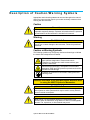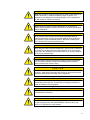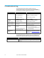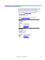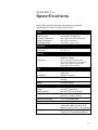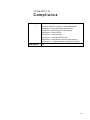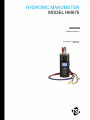
1
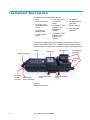
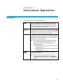
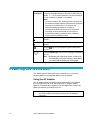
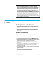
HYDRONIC MANOMETER MODEL HM675 OWNER’S MANUAL P/N 6006821, REVISION A MAY 2013 HYDRONIC MANOMETER MODEL HM675 OWNER’S MANUAL P/N 6006821, REVISION A MAY 2013 SHIP TO/MAIL TO: TSI Incorporated 500 Cardigan Road Shoreview, MN 55126-3996 USA U.S. Technical Support: (800) 874-2811/(651) 490-2811 Fax: (651) 490-3824 E-mail address: [email protected] Website: http://www.tsi.com INTERNATIONAL Technical Support: (001 651) 490-2811 Fax: (001 651) 490-3824 Manual History The following is a manual history of the Hydronic Manometer Model HM675 Owner’s Manual (P/N 6006821). ii Revision Date A May 2013 Hydronic Manometer Model HM675 Warranty Part Number Copyright Address Fax No. E-mail Address Limitation of Warranty and Liability (effective June 2011) 6006821 / Revision A / May 2013 ©TSI Incorporated / 2013 / All rights reserved. TSI Incorporated / 500 Cardigan Road / Shoreview, MN 55126 / USA 651-490-3824 [email protected] (For country-specific terms and conditions outside of the USA, please visit www.tsi.com.) Seller warrants the goods sold hereunder, under normal use and service as described in the operator's manual, shall be free from defects in workmanship and material for twenty-four (24) months, or if less, the length of time specified in the operator's manual, from the date of shipment to the customer. This warranty period is inclusive of any statutory warranty. This limited warranty is subject to the following exclusions and exceptions: a. Hot-wire or hot-film sensors used with research anemometers, and certain other components when indicated in specifications, are warranted for 90 days from the date of shipment; b. Pumps are warranted for one year or 3000 hours; whichever comes first; c. Parts repaired or replaced as a result of repair services are warranted to be free from defects in workmanship and material, under normal use, for 90 days from the date of shipment; d. Seller does not provide any warranty on finished goods manufactured by others or on any fuses, batteries or other consumable materials. Only the original manufacturer's warranty applies; e. Unless specifically authorized in a separate writing by Seller, Seller makes no warranty with respect to, and shall have no liability in connection with, goods which are incorporated into other products or equipment, or which are modified by any person other than Seller. The foregoing is IN LIEU OF all other warranties and is subject to the LIMITATIONS stated herein. NO OTHER EXPRESS OR IMPLIED WARRANTY OF FITNESS FOR PARTICULAR PURPOSE OR MERCHANTABILITY IS MADE. WITH RESPECT TO SELLER’S BREACH OF THE IMPLIED WARRANTY AGAINST INFRINGEMENT, SAID WARRANTY IS LIMITED TO CLAIMS OF DIRECT INFRINGEMENT AND EXCLUDES CLAIMS OF CONTRIBUTORY OR INDUCED INFRINGEMENTS. BUYER’S EXCLUSIVE REMEDY SHALL BE THE RETURN OF THE PURCHASE PRICE DISCOUNTED FOR REASONABLE WEAR AND TEAR OR AT SELLER’S OPTION REPLACEMENT OF THE GOODS WITH NON-INFRINGING GOODS. TO THE EXTENT PERMITTED BY LAW, THE EXCLUSIVE REMEDY OF THE USER OR BUYER, AND THE LIMIT OF SELLER'S LIABILITY FOR ANY AND ALL LOSSES, INJURIES, OR DAMAGES CONCERNING THE GOODS (INCLUDING CLAIMS BASED ON CONTRACT, NEGLIGENCE, TORT, STRICT LIABILITY OR OTHERWISE) SHALL BE THE RETURN OF GOODS TO SELLER AND THE REFUND OF THE PURCHASE PRICE, OR, AT THE OPTION OF SELLER, THE REPAIR OR REPLACEMENT OF THE GOODS. IN THE CASE OF SOFTWARE, SELLER WILL REPAIR OR REPLACE DEFECTIVE SOFTWARE OR IF UNABLE TO DO SO, WILL REFUND THE PURCHASE PRICE OF THE SOFTWARE. IN NO EVENT SHALL SELLER BE LIABLE FOR LOST PROFITS OR ANY SPECIAL, CONSEQUENTIAL OR INCIDENTAL DAMAGES. SELLER SHALL NOT BE RESPONSIBLE FOR INSTALLATION, DISMANTLING OR REINSTALLATION iii COSTS OR CHARGES. No Action, regardless of form, may be brought against Seller more than 12 months after a cause of action has accrued. The goods returned under warranty to Seller's factory shall be at Buyer's risk of loss, and will be returned, if at all, at Seller's risk of loss. Buyer and all users are deemed to have accepted this LIMITATION OF WARRANTY AND LIABILITY, which contains the complete and exclusive limited warranty of Seller. This LIMITATION OF WARRANTY AND LIABILITY may not be amended, modified or its terms waived, except by writing signed by an Officer of Seller. Trademarks CompuDat is a trademark of TSI Incorporated. TSI and the TSI logo are registered trademark of TSI Incorporated. Microsoft, Excel, Windows, and Vista are registered trademarks of Microsoft Corporation. iv Hydronic Manometer Model HM675 Contents Manual History .........................................................................................0-ii Warranty ..................................................................................................0-iii About This Manual .................................................................................0-iii Formatting and Typography ............................................................... 0-iii Technical Assistance—Help! ............................................................. 0-iii Safety Information ...................................................................................0-v Labels .................................................................................................. 0-v Description of Caution/Warning Symbols .......................................... 0-vi Caution............................................................................................ 0-vi Warning........................................................................................... 0-vi Caution or Warning Symbols .......................................................... 0-vi CHAPTER 1 Introduction ........................................................................1-1 Instrument Description ........................................................................1-2 Unpacking ...........................................................................................1-3 CHAPTER 2 Instrument Operation ........................................................2-1 Keypad ................................................................................................2-1 Powering the Instrument .....................................................................2-2 Using the AC Adapter ......................................................................2-2 Battery Installation ...........................................................................2-3 Battery Charging ..............................................................................2-4 Zeroing the Manometer .......................................................................2-6 Zeroing the Gauge Pressure Sensor ...............................................2-6 Zeroing the Differential Pressure Sensor ........................................2-6 Connecting the Manometer to the Test Points....................................2-7 Attaching the Hoses to the Manometer ...........................................2-7 Bleeding the Entrained Air ...............................................................2-7 Attaching the Hoses to the Test Points ...........................................2-8 Performing Pressure Measurements ..................................................2-8 Pressure Measurement Screen .......................................................2-8 Continuous Measurements ..............................................................2-9 Discrete Pressure Measurements ...................................................2-9 Performing Temperature Measurements ............................................2-9 Connecting the Temperature Probe ................................................2-9 Disconnecting the Manometer from the Test Points .........................2-10 CHAPTER 3 Maintenance and Troubleshooting ..................................3-1 Routine Maintenance ..........................................................................3-1 Draining the Hoses ..........................................................................3-1 Draining the Manometer Valve ........................................................3-1 In-Line Flow Restrictor .....................................................................3-2 Cleaning the In-line Flow Restrictors ...............................................3-2 Cleaning the Instrument Housing ....................................................3-2 Calibration ...........................................................................................3-3 i Troubleshooting ..................................................................................3-4 Technical Contacts..............................................................................3-5 APPENDIX A Specifications .................................................................. A-1 APPENDIX B Compliance ...................................................................... B-1 ii Hydronic Manometer Model HM675 About This Manual This manual explains how to set up, operate, and maintain the TSI® Hydronic Manometer Model HM675. Please read it thoroughly before using the instrument. Formatting and Typography Step-by-step instructions are numbered: 1, 2, 3, etc., set flush-left against the inside margin. References to keys on the manometer and the instrument's displayed readout are represented in bold typeface. In addition to the different typeface, displayed messages appear in quotes. Technical Assistance—Help! For technical assistance or questions about the instrument or this manual, or if the HM675 Hydronic Manometer needs repair or recalibration, call Technical Support at (651) 490-2811 or (800) 874-2811. iii (This page intentionally left blank) iv Hydronic Manometer Model HM675 Safety Information Carefully read each of the following safety warnings prior to using the HM675 Hydronic Manometer. This section gives instructions to promote safe and proper handling of the HM675 Hydronic Manometer. IMPORTANT There are no user-serviceable parts inside the instrument. Refer all repair and maintenance to a qualified factory-authorized technician. All maintenance and repair information in this manual is included for use by a qualified factory-authorized technician. Labels Identification and calibration labels are attached to the outside of the hydronic manometer housing. 1. Serial number label (back panel) ) 2. Calibration label (back panel) 3. European symbol for non-disposable item. Item must be recycled. v Description of Caution/Warning Symbols Appropriate caution/warning statements are used throughout the manual and on the instrument that require you to take cautionary measures when working with the instrument. Caution C a u t i o n Failure to follow the procedures prescribed in this manual might result in irreparable equipment damage. Important information about the operation and maintenance of this instrument is included in this manual. Warning W A R N I N G Warning means that unsafe use of the instrument could result in serious injury to you or cause damage to the instrument. Follow the procedures prescribed. Caution or Warning Symbols The following symbols may accompany cautions and warnings to indicate the nature and consequences of hazards: Warns that uninsulated voltage within the instrument may have sufficient magnitude to cause electric shock. Therefore, it is dangerous to make contact with any part inside the instrument. Warns that the instrument is susceptible to electro-static dissipation (ESD) and ESD protection procedures should be followed to avoid damage. Indicates the connector is connected to earth ground and cabinet ground. Carefully read each of the following safety warnings prior to using the HM675 Hydronic Manometer. W A R N I N G Never use the HM675 Hydronic Manometer or accessories on potable water systems or other systems which may be used to convey fluids for human or animal consumption. W A R N I N G Never charge non-rechargeable batteries by setting battery-type selection switch to NiMH when using alkaline or other non-rechargeable batteries. Fire, explosions, or other hazards may result. vi Hydronic Manometer Model HM675 C a u t i o n Never use the HM675 Hydronic Manometer to measure the pressure of volatile, flammable, or otherwise hazardous fluids or gasses. The instrument is not designed to be intrinsically safe, nor is it designed for use with caustic or corrosive chemicals. C a u t i o n Never connect the HM675 Hydronic Manometer or accessories to systems which exceed the instrument’s maximum pressure specification (300 psi; 2068 kPa). C a u t i o n Observe proper safety precautions and wear appropriate personal protective equipment, including gloves and eyewear, when working on high pressure or high temperature systems. Ruptured or leaking lines pose a potential risk of serious personal injury. C a u t i o n When using the HM675 Hydronic Manometer, verify all hose connections are secure prior to taking pressure measurements. Loose connections may result in the discharge of pressurized water or air, posing a potential risk of serious personal injury. C a u t i o n Exercise caution when disconnecting the HM675 Hydronic Manometer from a pressurized system. Water or air discharged under pressure poses a potential risk of severe injury. C a u t i o n Exercise caution in using the HM675 Hydronic Manometer near electrical equipment. Water spray associated with purging or disconnecting hoses presents a potential risk of damage to such equipment. C a u t i o n Thoroughly drain and dry the HM675 Hydronic Manometer hoses and internal piping after each use. This will help in limiting the potential for growth of hazardous microorganisms. C a u t i o n Never plug into the instrument any power supply other than the one provided with the instrument. C a u t i o n Always make certain that the battery switch is in the correct position for the type of battery being used (Alkaline/NiMH). Failure to do so may result in Fire, Explosions or other hazard. vii C a u t i o n Never use Alkaline and NiMH batteries together on the same instrument. C a u t i o n Always use the hoses with the provided Flow Restrictor connected in line with the shut-off valves to prevent “Water Hammer.” Water Hammer is a fast moving shock wave of pressure caused by sudden changes in the system such as a valve being opened or closed or a pump being turned on or off. viii Hydronic Manometer Model HM675 CHAPTER 1 Introduction The HM675 Hydronic Manometer is an easy-to-use instrument designed for the accurate measurement of pressure in non-potable water and air systems. Features of the manometer include the following: Single-function keys for ease of use Simultaneous measurement and display of High-side gauge and Differential pressure Calculation and display of Low-side gauge pressure User-selectable units of measure User-selectable time constant Easy to read LCD with backlight Power input via AC adapter or batteries (alkaline or rechargeable NiMH) Internal NiMH battery charging Automatic power shutoff Splash-proof case Rugged carrying case for storage of meter, hoses, accessories, tools, and paperwork 1-1 Instrument Description The HM675 Hydronic Manometer includes: Meter Hard carrying case (2) 6-foot (1.8 m) hoses with shut-off valves (2) P/T gauge adapter probes (2) B&G readout probes (2) ¼” Flare male × ¼” male NPT fittings AC adapter (2) Female ¼” NPT to Male ¼” ISO Parallel Pipe Threads (2) Female ¼” NPT to Male ¼” ISO Tapered Pipe Threads Owner’s manual (4) NiMH batteries, neck strap NIST traceable certificate An accessory temperature probe is available as an optional tool for the HM675 Hydronic Manometer. The 18” diameter, stainless steel sheathed immersion probe is designed for measurement of water line temperatures. Keypad LCD Display Valve Handle Bottom Port Cover Neck/Hanging Strap Clips Pressure Ports AC Power Adapter Input Port USB Port (for factory calibration) Temperature Probe Port 2 Figure 1-1 HM675 Meter Description 1-2 Hydronic Manometer Model HM675 Temperature Probe Port 1 Unpacking As you unpack the instrument and accessories, check the components against your packing list. If any parts are missing or damaged, notify TSI immediately. Tables 1-1 and 1-2 list available standard and optional components for the HM675 Hydronic Manometer. Table 1-1 Standard Components Item Part No. Carrying case 1319409 Blue and red hose kit with shut-off valves and flow restrictor 6006813 P/T gauge adapter probes (2) 632360004 B&G readout probes (2) 632360010 AC adapter 6004983 AA-size NiMH battery, four required 1208048 Battery holder 1801206 Neck strap 2913011 Owner’s manual 1980517 Pocket screw driver 3012054 Table 1-2 Optional Components Item Accessory fittings kit (USA only) Part No. HMFIT 4 in. (10 cm) long, 0.125 in. (3.175 mm) dia. Temperature probe 801290 External battery charger with (4) AA NiMH batteries (USA only) 801093 Please register your HM675 promptly through our website at http://register.tsi.com. Registration of your product allows us to notify you of product updates. Introduction 1-3 (This page intentionally left blank) 1-4 Hydronic Manometer Model HM675 CHAPTER 2 Instrument Operation Keypad Each key and its function are described below. READ Pressing the READ key initiates taking a time-averaged reading based on the current setting of the time constant (TC). Upon taking the reading, the values are displayed onscreen for a period of ten (10) seconds. UNITS GAUGE Pressing the UNITS GAUGE key allows for toggling through the available units for gauge pressure measurements (High P and Low P). The available units of measurement are: psi, inH2O, ftH2O, inHg, kPa, mH2O, mmHg, and bar. UNITS ΔP Pressing the UNITS ∆P key allows for toggling through the available units for differential pressure measurements (dP). The available units of measurement are: psi, inH2O, ftH2O, inHg, kPa, mH2O, mmHg, and bar. Note: When using the accessory temperature probe, the unit of measurement for temperature (°F or °C) is driven by the selected unit of measurement for differential pressure: Differential pressure in psi, inH2O, ftH2O, or inHg → temperature in °F Differential pressure in kPa, mH2O, mmHg, or bar → temperature in °C ZERO GAUGE Pressing the ZERO GAUGE key initiates zeroing of the gauge pressure sensor. Note: Proper zeroing of the gauge pressure sensor is achieved with the High pressure (+) port open to atmosphere and the valve handle in the MEASURE position. 2-1 TIME CONSTANT Pressing the TIME CONSTANT key allows for toggling through the available settings for the time constant (TC) as follows: 1, 5, 10, 20, and 30 seconds. The current setting of the time constant is indicated on the display. Notes: The time constant is the sampling period over which the manometer averages pressure measurements. Example: with the time constant equal to 10 seconds, the displayed reading represents the average of measurements taken over the previous 10 seconds. Increasing the time constant will serve to improve measurement stability, particularly when measuring systems with fluctuating pressures. CONTRAST Press the CONTRAST ▲ key to increase the display contrast. CONTRAST Press the CONTRAST ▼ key to decrease the display contrast. Press the on or off. key to turn the HM675 Hydronic Manometer Press the BACKLIGHT key to turn the display’s backlighting on or off. Note: Backlighting has a significant impact on battery life. Use backlighting only when working in areas where you cannot read the display with existing light. Powering the Instrument The HM675 Hydronic Manometer can be powered by four (4) AA-size batteries (alkaline or rechargeable NiMH) or the AC adapter. Using the AC Adapter The AC adapter allows the HM675 Hydronic Manometer to be powered from a standard AC wall outlet. When using the AC adapter, alkaline batteries (if installed) will be bypassed. The AC adapter also charges the NiMH type batteries (if installed) in the unit. Note 2-2 With the battery-type selection switch set to NiMH, the manometer will initiate charging the batteries whenever the AC adapter is connected. Hydronic Manometer Model HM675 C a u t i o n Only use TSI P/N 6004983, the AC adapter supplied with the instrument, when powering the HM675 Hydronic Manometer externally. Do not connect the AC adapter or car adapter provided with the battery optional charger (801093) or any other AC adapter to the HM675/685. Using any other power cable or power supply may cause damage to the device and void the warranty. WARNING Never charge non-rechargeable batteries by setting battery-type selection switch to NiMH with alkaline or other non-rechargeable batteries. Fire, explosions, or other hazards may result. C a u t i o n Never plug into the instrument any power supply other than the one provided with the instrument. Battery Installation To install/replace the batteries: 1. Turn the manometer off and locate the battery cover on the back of the unit. 2. Loosen the screw on the battery compartment cover and lift to remove. 3. Remove the battery holder. Tapping the backside of the meter against your hand may assist in removing the battery holder. 4. Remove the old batteries and replace with fresh batteries (alkaline or rechargeable NiMH). Ensure that the batteries are correctly oriented within the battery holder. 5. Set the battery-type selection switch to indicate the type of batteries to be used (alkaline or rechargeable NiMH). Battery Type Selection Switch Figure 2-1 Location of Battery-Type Selection Switch Instrument Operation 2-3 WARNING Do not use Lithium batteries in this instrument. Fire, explosions, or other hazards may result. C a u t i o n Never use Alkaline and NiMH batteries together on the same instrument. C a u t i o n Always make certain that the battery switch is in the correct position for the type of battery being used (Alkaline/NiMH). Failure to do so may result in Fire, Explosions, or other hazard. 6. Reinstall the battery holder. Ensure the battery holder orientation is such that its terminals make contact with the spring contacts within the battery compartment. 7. Replace the battery compartment cover. Notes: The NiMH batteries included with the instrument may require recharging prior to first use. Fully charged batteries should enable the instrument to operate for a period of at least twelve (12) hours Setting the battery-type selection switch properly will prevent unwanted charging of non-rechargeable alkaline batteries and provide charging of NiMH batteries when the AC adapter is connected. A battery charge life remaining indicator is shown on the display whenever the manometer is powered by batteries, and turned on. When using NiMH batteries, the indicator of battery charge life remaining will not be accurate due to their inherent non-linear voltage drop with power use. Due to the danger of battery leakage, remove batteries from the battery compartment prior to storage. Never mix battery types. For maximum battery life, ensure backlight is “off” when not needed. Battery Charging WARNING Do not use Lithium batteries in this instrument. Fire, explosions, or other hazards may result. C a u t i o n Never plug into the instrument any power supply other than the one provided with the instrument. 2-4 Hydronic Manometer Model HM675 C a u t i o n Always make certain that the battery switch is in the correct position for the type of battery being used (Alkaline/NiMH). Failure to do so may result in Fire, Explosions or other hazard. C a u t i o n Never use Alkaline and NiMH batteries together on the same instrument. The HM675 Hydronic Manometer allows for internal charging of AA-size type NiMH (only) batteries. Charging of the batteries is initiated as follows: 1. Turn the manometer off and locate the battery cover on the back of the unit. 2. Loosen the screw on the battery compartment cover and lift to remove. 3. Remove the battery holder. Tapping the backside of the meter against your hand may help in removing the battery holder. 4. Verify the batteries installed are rechargeable type NiMH. 5. Set the battery-type selection switch to NiMH (see Figure 2-1). 6. Reinstall the battery holder. Ensure the battery holder orientation is such that its terminals make contact with the spring contacts within the battery compartment. 7. Replace the battery compartment cover. 8. Plug in the AC adapter. Notes: Full charge of the batteries is achieved within four (4) hours. Fully charged batteries should enable the instrument to operate for a period of at least twelve (12) hours. The manometer remains fully operational while charging batteries. Never attempt to charge battery types other than AA-size rechargeable NiMH. For maximum battery life, ensure the backlight is “off” when not needed. Never mix battery types. NiMH batteries should only be charged at room temperature. Starting with batteries that are too cold or too warm can cause the charge cycle to terminate early. Instrument Operation 2-5 Zeroing the Manometer The HM675 Hydronic Manometer is equipped with both a gauge and differential pressure sensor, allowing for simultaneous measurement and display of High-side gauge and Differential pressure. The gauge and differential pressure sensors are zeroed independently of one another. Zeroing the Gauge Pressure Sensor To ensure the most accurate gauge pressure (High P) measurements, the HM675 gauge pressure sensor should be zeroed prior to taking readings on each new system. The gauge pressure sensor is zeroed as follows: 1. Disconnect the High pressure (red) hose from the manometer such that the High pressure (+) port is open to atmosphere. 2. Turn the valve handle on the manometer to the MEASURE position. 3. Press the ZERO GAUGE key. Follow on screen instruction to zero the gauge pressure sensor. 4. Allow the manometer to stand undisturbed for five (5) seconds until the zero gauge pressure sensor function has completed. Notes: Zeroing the gauge pressure sensor requires the user to disconnect the High pressure (red) hose; as such it is often most convenient to zero the gauge pressure sensor as part of the start-up sequence (i.e,. before hoses have been connected). The zero offset of the gauge pressure sensor is sensitive to temperature changes. If moving the manometer between areas of extreme temperature difference, it is best to allow the meter to settle to the new temperature prior to zeroing. Zeroing the Differential Pressure Sensor To ensure the most accurate differential pressure (dP) measurements, the HM675 differential pressure sensor should be zeroed prior to taking readings on each new system. The differential pressure sensor is zeroed as follows: 1. Go to the Measurement Screen. 2. Turn the valve handle on the manometer to the BYPASS position. 3. The instrument will automatically zero the differential pressure sensor. Follow the on-screen instructions and return the knob to MEASURE once this is done. 2-6 Hydronic Manometer Model HM675 Notes: Any pressures applied to the hoses will not affect the dP zeroing function. This feature allows for successful zeroing of the differential pressure sensor while maintaining connections to the system under test. Zeroing of the differential pressure sensor is initiated any time the valve handle has been turned to the BYPASS position with the meter turned on. This feature allows for successful zeroing of the differential pressure sensor while entrained air is being purged from the hoses. The zero offset of the differential pressure sensor is sensitive to temperature changes. If moving the manometer between areas with extreme temperature difference, it is best to allow the meter to settle to the new temperature prior to zeroing. Connecting the Manometer to the Test Points Attaching the Hoses to the Manometer 1. Connect the straight female flare fitting on the High pressure (red) hose to the male fitting on the top of the manometer marked with a plus (+) sign. 2. Connect the straight female flare fitting on the Low pressure (blue) hose to the male fitting on the top of the manometer marked with a minus (-) sign. Bleeding the Entrained Air To ensure the most accurate pressure measurements, purge all entrained air within the hoses as follows: 1. Turn the shut-off ball valve on both the High and Low pressure hoses to the closed position. 2. Turn the valve handle on the manometer to the MEASURE position. 3. Using an appropriate fitting, connect the open end of the High pressure (red) hose to the test point with the higher line pressure. 4. Attach the appropriate fitting to the open end of the Low pressure (blue) hose. 5. To ensure all the air is bled from the hoses, hold the open end of the Low pressure (blue) hose in an upright position over a suitable receptacle or near a drain. 6. Turn the shut-off ball valve on both the High and Low pressure hoses to the open position. 7. Turn the valve handle on the manometer to the BYPASS position to allow the liquid flow to displace the entrained air. Instrument Operation 2-7 Note: Zeroing of the differential pressure sensor is initiated any time the valve handle has been turned to the BYPASS position with the meter turned on. This feature allows for successful zeroing of the differential pressure sensor while entrained air is being purged from the hoses. 8. Once the liquid is flowing steadily from the Low pressure (blue) hose, turn the valve handle on the manometer to the MEASURE position. Note: The time to fully prime the hose with fluid may take up to one minute depending on the line pressure. Higher line pressure will reduce the bleed time. Attaching the Hoses to the Test Points 1. As indicated above, use an appropriate fitting to connect the open end of the High pressure (red) hose to the test point with the higher line pressure. 2. Using an appropriate fitting, connect the open end of the Low pressure (blue) hose to the test point with the lower line pressure. Note: If the hoses are connected in the inverse orientation (i.e., High pressure (red) hose to the lower line pressure), the displayed Highside gauge pressure (High P) will be less than the Low-side gauge pressure (Low P), and the Differential pressure (dP) will be negative. Performing Pressure Measurements The HM675 Hydronic Manometer allows for simultaneous measurement and display of the High-side gauge and Differential pressure. The calculated Low-side gauge pressure is also displayed. The manometer is equipped to make and display either discrete or continuous pressure measurements. Pressure Measurement Screen *Shown with two optional accessory temperature probes attached. 2-8 Hydronic Manometer Model HM675 High-Side Gauge Pressure The High-side gauge pressure measurement is indicated as High on the manometer display. Low-Side Gauge Pressure The Low-side gauge pressure reading is indicated as Low on the manometer display. It represents a calculated value determined from the measured High-side gauge and Differential pressure as follows: Low P = High P – dP Differential Pressure The Differential pressure measurement is indicated as dP on the manometer display. Continuous Measurements The HM675 Hydronic Manometer continuously measures and displays pressure readings whenever the manometer is turned on, with the exception of when the READ key is pressed. When the READ key is pressed, the displayed readings are averaged measurements taken over the sampling period as defined by the current time constant setting. The display is updated once per second. Discrete Pressure Measurements Taking a discrete pressure measurement allows for measurement and display of a single time-averaged reading taken over the sampling period as defined by the current time constant setting. Discrete pressure measurement values are displayed on-screen for a period of 10 seconds and then returns to continuous measurement mode. 1. Press the READ key. 2. Allow the manometer to stand undisturbed until the reading is complete (time of completion dependent on the time constant setting). Performing Temperature Measurements The accessory temperature probe is an optional tool for the HM675 Hydronic Manometer. The 1/8” diameter, stainless steel sheathed immersion probe is designed for measurement of water line temperatures. When using the accessory temperature probe, the HM675 Hydronic Manometer is equipped to make and display either discrete or continuous temperature measurements. Two temperature probes can be connected to the instrument to measure upstream and downstream temperature simultaneously. Connecting the Temperature Probe Connect the keyed 3-pin plug of the accessory temperature probe to the mating connector located on the right-hand side of the manometer. Instrument Operation 2-9 Notes: A locking nut is provided on the accessory temperature probe plug to allow for a more secure attachment when connecting to the manometer. When using the accessory temperature probe, the unit of measurement for temperature (°F or °C) is driven by the selected unit of measurement for differential pressure: Differential pressure in psi, inH2O, ftH2O, or inHg → temperature in °F Differential pressure in kPa, mH2O, mmHg, or bar → temperature in °C Disconnecting the Manometer from the Test Points C a u t i o n Exercise caution when disconnecting the HM675 Hydronic Manometer from a pressurized system. Water or air discharged under pressure poses a potential risk of severe injury. C a u t i o n Exercise caution in using the HM675 Hydronic Manometer near electrical equipment. Water spray associated with purging or disconnecting hoses presents a potential risk of damage to such equipment. C a u t i o n Thoroughly drain and dry the HM675 Hydronic Manometer hoses and internal piping after each use. This will help in limiting the potential for growth of hazardous microorganisms. The following provides a guideline for disconnecting the manometer from the test points once measurements have been completed. 1. Turn the shut-off ball valve on both the High and Low pressure hoses to the closed position. 2. Disconnect the High pressure (red) hose from the higher line pressure test point. 3. Disconnect the Low pressure (blue) hose from the lower line pressure test point. Note: If additional measurements at another location/system containing the same fluid are to be made, it is not necessary to proceed to step 4 and drain the fluid entrained within the hoses at this time. The fluid remaining within the hoses will help minimize the time necessary to bleed entrained air prior to making subsequent measurements. 4. Place the open end of the Low pressure (blue) hose in a suitable receptacle or near a drain. 2-10 Hydronic Manometer Model HM675 5. Turn the valve handle on the manometer to the BYPASS position. 6. Turn the shut-off ball valve on the Low pressure (blue) hose to the open position to discharge the pressurized fluid out of the open end of the Low pressure (blue) hose. 7. Elevate the High pressure (red) hose and turn its shut-off ball valve to the open position to allow for draining of the remaining entrained fluid. Instrument Operation 2-11 (This page intentionally left blank) 2-12 Hydronic Manometer Model HM675 CHAPTER 3 Maintenance and Tr o u b l e s h o o t i n g The HM675 Hydronic Manometer has been designed to provide long-term field use with minimum required maintenance. As with any precision electronic device, however, proper care, maintenance, and handling will further ensure its accurate and reliable operation. IMPORTANT There are no user-serviceable parts inside this instrument. Opening the instrument case may void the warranty. TSI recommends that you return the HM675 Hydronic Manometer to the factory for any required maintenance or service not described in this manual. Routine Maintenance The following guidelines should be followed whenever storing the HM675 Hydronic Manometer: Draining the Hoses Fluid within the High (red) and Low (blue) pressure hoses should be properly drained whenever the instrument is being stored after use. 1. Disconnect the manometer hoses from the test points (Reference Chapter 2, "Disconnecting the Manometer from the Test Points"). 2. Disconnect the High (red) and Low (blue) pressure hoses from the manometer. 3. Turn the shut-off ball valve on both the High and Low pressure hoses to the open position. 4. Using a suitable high pressure air source, blow the entrained liquid from both hoses. Draining the Manometer Valve Fluid within the manometer valve should be properly drained whenever the instrument is being stored after use. 1. Disconnect the High (red) and Low (blue) pressure hoses from the manometer. 2. Turn the valve handle on the manometer to the BYPASS position. 3. Hold the manometer with the pressure ports directed downward to allow liquid to drain from the unit. 3-1 4. Turn the valve handle on the manometer to the MEASURE position. 5. Hold the manometer with the pressure ports directed downward to allow liquid to drain from the unit. Note: The HM675 Hydronic Manometer should be stored with the valve handle in the MEASURE position. In-Line Flow Restrictor The blue and red hose assemblies include flow restrictors. The flow restrictors must be used to prevent damage to the pressure sensors from unexpected water hammering or pressure spikes and also acts as a filter. Do not use the HM675 Hydronic Manometer without the flow restrictors installed in the hose assemblies or sensor damage or clogging will occur. Short Hose Section Flow Restrictor Shut-Off Valve Cleaning the In-line Flow Restrictors These flow restrictors should be flushed periodically with clean water to minimize potential clogging. 1. Disconnect the hose from the manometer. 2. Turn the shut-off ball valve on the hose to the closed position. 3. Connect the straight female flare fitting (farthest from the hose shut-off valve) on the hose to a suitable water source. 4. Place the open end of the hose in a suitable receptacle or near a drain. 5. Turn the shut-off ball valve on the hose to the open position and allow water to flush through for several minutes. 6. Using a suitable high pressure air source, blow the entrained water from the hose. 7. Repeat with the second hose. Note: If necessary, remove the flow restrictor for further cleaning or flushing. Reattach to hose assembly when complete. Cleaning the Instrument Housing The HM675 Hydronic Manometer may be cleaned using a soft, damp, clean cloth. Note: 3-2 Do not use solvents or abrasive cleaners to clean the instrument housing, keypad, or display. Hydronic Manometer Model HM675 Calibration TSI recommends that the HM675 Hydronic Manometer receive an annual calibration. TSI will verify calibration of the instrument and re-issue a certificate of calibration with traceability to NIST. This “annual checkup” helps to ensure the specified accuracy of the instrument is maintained. To calibrate the instrument, please ship TSI the complete package that includes the meter and accessory temperature probe. Everything should be packed carefully within the carrying case and then inside a shipping box. The original shipping box and packaging (carton and foam) is preferred. Before returning the Hydronic Manometer to TSI for service, visit our website at http://rma.tsi.com or call TSI at 1-800-874-2811 (USA) or 001 (651) 490-2811 for specific return instructions. Customer Service will need the following information when you call: The instrument model number The instrument serial number A purchase order number (unless under warranty) A billing address A shipping address (continued on next page) Maintenance and Troubleshooting 3-3 Troubleshooting The following table lists the symptoms, possible causes, and recommended solutions for common problems encountered with the instrument. If your symptom is not listed, or if the recommended solutions do not address your problem, please contact the factory. Symptom No display “ “ flashing on display “8888” flashing on display “-----” on display Instrument unresponsive to pressure Possible Causes Unit not turned on. Corrective Action Press On/OFF key. Low or dead batteries. Replace or recharge the batteries. Dirty battery contacts. Clean the battery contacts. AC adapter not connected. Low battery charge. Plug in AC adapter. Replace or recharge the batteries. Dirty battery contacts. Clean the battery contacts. The indicated measurement is out of range. The allowable ranges for pressure and temperature measurements are shown on the specifications page. Try one of the below two steps: 1. Plug in temperature probe. 2. Return the pressure measurement to the correct range The temperature sensor is unplugged The pressure measurement is out of the meter’s range. Hoses are clogged Make sure hoses and flow restrictors are unclogged from any debris by following instructions on Cleaning the In-line Flow Restrictors. The following table lists error messages which can be displayed should the instrument detect a problem. Should any of these error messages recur repeatedly, the instrument should be returned to the factory for servicing. 3-4 Error Message Possible Causes & Corrective Action "Saved Pressure Zero” There was a problem with a pressure zero reading read from memory. Differential pressure and gauge pressure should both be re-zeroed. Hydronic Manometer Model HM675 Technical Contacts If you have any difficulty installing the Hydronic Manometer, or if you have technical or application questions about this instrument, contact an applications engineer at one of the locations listed below. If the Hydronic Manometer fails, or if you are returning it for service, visit our website at http://service.tsi.com or contact TSI at: TSI Incorporated 500 Cardigan Road Shoreview, MN 55126 USA Phone: +1-800-874-2811 (USA) or +1 (651) 490-2811 E-mail: [email protected] TSI GmbH Neuköllner Strasse 4 52068 Aachen GERMANY Telephone: Fax: E-mail: Web: +49 241-52303-0 +49 241-52303-49 [email protected] www.tsiinc.de TSI Instruments Ltd. Stirling Road Cressex Business Park High Wycombe, Bucks HP12 3ST UNITED KINGDOM Telephone: Fax: E-mail: Web: +44 (0) 149 4 459200 +44 (0) 149 4 459700 [email protected] www.tsiinc.co.uk Maintenance and Troubleshooting 3-5 (This page intentionally left blank) 3-6 Hydronic Manometer Model HM675 APPENDIX A Specifications Model HM675 Hydronic Manometer specifications are as follows (specifications are subject to change without notice). Range Differential Pressure ................ Gauge Pressure ...................... Operating Temperature ........... Storage Temperature .............. Temperature Probe ................. 0 to 300 psi (0 to 2068 kPa) 0 to 300 psi (0 to 2068 kPa) 40 to 100°F (4 to 38°C) electronics 0 to 140°F (-18 to 60°C) -40 to 250°F (-40 to 121°C) Resolution Pressure (best) ........................ Temperature ............................ 0.001 psi (0.01 kPa) 0.1°F (0.1°C) Accuracy Pressure1 ................................. Temperature ............................ ±1% of reading or .072 psi (0.5 kPa), whichever is greater ±0.5°F (0.3°C) from 32 to 160°F (0 to 71°C); max ±2.0°F (1.2°C) from -40 to 32°F (-40 to 0°C) and from 160 to 250°F (71 to 121°C) Units Pressure .................................. Temperature ............................ Time Constant ........................ psi, in. H2O, ft H2O, kPa, mm Hg, in. Hg, m H2O, bar degrees F, degrees C user selectable (1, 5, 10, 20, and 30 seconds) Display .................................... LCD with backlight Instrument Temperature Range Operating (Electronics) ............ 40 to 113°F (5 to 45°C) Storage .................................... -4 to 140°F (-20 to 60°C) Relative humidity ..................... up to 95% RH, non-condensing Dimensions (meter only) ........ 11.1 in. × 4.7 in. × 3.5 in. (28.2 cm × 11.9 cm × 8.8 cm) Pressure Connection ............ ¼” 37° Flare Fitting, Male Weight with Batteries ............ 2.65 lb. (1.20 kg) Power Requirements ............. four AA-size cells, alkaline or rechargeable NiMH (included), or AC adapter (included) 9 VDC, 2 A, regulated Battery Life2............................ minimum of 12 hours with backlight on minimum of 18 hours with backlight off A-1 Recharge Time ....................... 4 hours (internal charger) Warranty ................................. 2-year factory warranty 1 Accuracy statement applies from 0 to 250 psi (0 to 1724 kPa). 2 The minimum battery life stated will occur after the NiMH batteries have been recharged 2 to 3 times after initial charge. A-2 Hydronic Manometer Model HM675 APPENDIX B Compliance CE Marking EN61326 / EN 55011, Class B: Radiated Emissions EN61326 / EN 55011, Class B: Conducted Emissions EN61000-4-2: Electrostatic Discharge Immunity EN61000-4-3: Electromagnetic Field Immunity EN61000-4-4: Burst Immunity EN61000-4-5: Surge Immunity EN61000-4-6: Conducted PS Immunity EN61000-4-8: Rated Power-Frequency Field Immunity EN61000-4-11: Voltage Dips\Short Interruptions Immunity RoHS Marking Yes B-1 (This page intentionally left blank) B-2 Hydronic Manometer Model HM675 TSI Incorporated – Visit our website www.tsi.com for more information. USA UK France Germany Tel: +1 800 874 2811 Tel: +44 149 4 459200 Tel: +33 4 91 11 87 64 Tel: +49 241 523030 P/N 6006821 Rev A India China Singapore ©2013 TSI Incorporated Tel: +91 80 67877200 Tel: +86 10 8219 7688 Tel: +65 6595 6388 Printed in U.S.A.