1
Telindus 1431 SHDSL CPE
Telindus 1431 SHDSL CPE
User and reference manual
Version: 2.1 - 201604
Telindus Technical Publications – Geldenaaksebaan 335 - B-3001 Leuven - Belgium – Tel. +32 16 382011
ii Telindus 1431 SHDSL CPE
Copyright, safety and statements
User and reference manual
Document properties
Subject
Telindus 1431 SHDSL CPE
Manual type
User and reference manual
Version
2.1
Code
201604
Modification date
20 December 2005 ©Telindus
Copyright notice
The information and descriptions contained in this publication are the property of Telindus. Such information and descriptions must not be copied or reproduced by any means, or disseminated or distributed
without the express prior written permission of Telindus.
This publication could include technical inaccuracies or typographical errors, for which Telindus never
can or shall be held liable. Changes are made periodically to the information herein; these changes will
be incorporated in new editions of this publication. Telindus may make improvements and/or changes in
the product(s) described in this publication at any time, without prior notice.
Safety requirements
Carefully read the safety instructions, installation precautions and connection precautions as stated in
chapter 2 - Installing and connecting the Telindus 1431 SHDSL CPE on page 11.
Telindus 1431 SHDSL CPE
Copyright, safety and statements iii
User and reference manual
Statements
www.telindusproducts.com → Telindus Access Solutions → Products → Choose a product → Downloads → Certificates
Hereby, Telindus declares that this Telindus 1431 SHDSL CPE complies with the essential requirements
and other relevant provisions of Directive 1999/5/EC.
Hierbij verklaart Telindus dat deze Telindus 1431 SHDSL CPE overeenstemt met de essentiële vereisten en andere relevante bepalingen van Richtlijn 1999/5/EC.
Par la présente, Telindus déclare que ce Telindus 1431 SHDSL CPE est en conformité avec les exigences essentielles et autres articles applicables de la Directive 1999/5/EC.
Hiermit, Telindus erklärt daß dieser Telindus 1431 SHDSL CPE in Fügsamkeit ist mit den wesentlichen
Anforderungen und anderen relevanten Bereitstellungen von Direktive 1999/5/EC.
Mediante la presente, Telindus declara que el Telindus 1431 SHDSL CPE cumple con los requisitos
esenciales y las demás prescripciones relevantes de la Directiva 1999/5/CE.
A Telindus declara que o Telindus 1431 SHDSL CPE cumpre os principais requisitos e outras disposições da Directiva 1999/5/EC.
Col presente, Telindus dichiara che questo Telindus 1431 SHDSL CPE è in acquiescenza coi requisiti
essenziali e stipulazioni attinenti ed altre di Direttivo 1999/5/EC.
Με το παρόν η Telindus δηλώνει ότι το Telindus 1431 SHDSL CPE είναι συμμορφούμενο με τις βασικές
απαιτήσεις και με τις υπόλοιπες σχετικές διατάξες της οδηγίας 1999/5/EC.
iv Telindus 1431 SHDSL CPE
Copyright, safety and statements
User and reference manual
Environmental information
The crossed-out wheeled bin means that within the European Union the product must be taken to separate
collection at the product end of life. This applies to the device but also to any accessories marked with this
symbol. Do not dispose of these products as unsorted municipal waste.
If you need more information on the collection, reuse and recycling systems, please contact your local waste
administration. You can also contact us for more information on the environmental specifications of our products.
De doorgestreepte container wil zeggen dat binnen de Europese gemeenschap het product voor gescheiden afvalverzameling
moet worden aangeboden aan het einde van de levensduur van het product. Dit geldt voor het toestel, maar ook voor alle
toebehoren dia van dit symbool voorzien zijn. Bied deze producten niet aan bij het gewone huisvuil.
Indien u meer informatie wenst over de systemen voor inzameling, hergebruik en recyclage, gelieve dan uw lokale afvaldiensten
te contacteren. U kan ook ons contacteren wanneer u informatie wenst over de milieu aspecten van onze producten.
Le symbole de la poubelle sur roues barrée d’une croix signifie que ce produit doit faire l’objet d’une collecte sélective en fin de
vie au sein de l’Union Européenne. Cette mesure s’applique non seulement à vorte appareil mais également à tout autre
accessoire marqué de ce symbole. Ne jetez pas ces produits dans les ordures ménagères non sujettes au tri sélectif.
Si vous souhaitez plus d'information concernant les systèmes de collecte, de réutilisation et de recyclage, veuillez contactez votre
service de gestion de déchets local. Vous pouvez également nous contacter pour obtenir plus d’information au sujet des
spécifications environnementales de nos produits.
Das Symbol der durchgestrichenen Abfalltonne auf Rädern bedeutet dass das Produkt in der Europäischen Union einer
getrennten Mülsammlung zugeführt werden muss. Dies gilt sowohl für das Produkt selbst, als auch für alle mit diesem Symbol
gekennzeichneten Zubehörteile. Diese Produkte dürfen nicht über den unsortierten Hausmüll entsorgt werden.
Wenn Sie mehr Informationen brauchen über die Sammlung und Recycling Systemen, bitte konsultieren Sie Ihre örtliche Abfälle
Verwaltung. Für mehr Informationen über die Umweltaspekten unserer Produkte, wenden Sie sich an unserer Kundendienst.
Telindus 1431 SHDSL CPE
Preface v
User and reference manual
Documentation set
The documentation set of the Telindus 1431 SHDSL CPE currently consists of the following:
Document
Description
Telindus 1431 SHDSL CPE
manual (this manual)
This is the manual you are reading now.
maintenance and management application manuals
The Telindus 1431 SHDSL CPE can be maintained and managed by
a variety of maintenance and management tools. Refer to 1.4 - Maintenance and management tools on page 8 for an introduction on
these tools and for a reference to the manual of these tools.
cable documents
A wide variety of cables exist to connect the Telindus 1431 SHDSL
CPE. The Data cables document (PDF) and the Management cables
document (PDF) describe these cables.
It shows you how to install and connect the Telindus 1431 SHDSL
CPE and gives you a basic configuration. It also contains a complete
description of all the configuration, status, performance and alarm
parameters for look-up purposes.
All these documents, together with the free maintenance tool TMA and the firmware of the Telindus
devices, can be found on the Telindus Access Products distribution CD that is delivered with all Telindus
products.
Organisation of this manual
This manual contains the following main parts:
Part
This part …
User manual
shows you how to install and connect the Telindus 1431 SHDSL CPE. It also
gives a basic configuration of the Telindus 1431 SHDSL CPE.
Reference manual
gives more detailed information on the Telindus 1431 SHDSL CPE, such as
software download procedures, technical specifications, etc. It also contains a
complete description of all the configuration, status, performance and alarm
parameters for look-up purposes.
Annex
gives additional information, such as product sales codes.
Refer to the Table of contents on page x for a detailed overview of this manual.
vi Telindus 1431 SHDSL CPE
Preface
User and reference manual
Typographical conventions
The following typographical conventions are used in this manual:
The format …
indicates …
Normal
normal text.
Italic
•
new or emphasised words
•
application windows, buttons and fields. E.g. In the Filename field enter …
Computer
text you have to enter at the DOS or CLI prompt, computer output and code
examples.
E.g. NOK,1,1,Invalid command.
Computer Bold
text you have to enter at the DOS or CLI prompt when it is part of a mix of computer input and output.
E.g.
/o1003:"Edit Configuration"
>get sysName
sysName = "Orchid 1003 LAN"
/o1003:"Edit Configuration"
>
Narrow
containment tree objects and attributes of a device when they are mentioned in
the normal text. I.e. when they are not a part of computer input or output.
E.g. Use the sysName attribute in order to …
<Narrow>
containment tree objects or attributes or part of them that are variable. I.e.
depending on the product version, used interface, etc. the names of these
objects or attributes are slightly different.
E.g. topObject/<modularIf>/someAttribute means that the name of the object
<modularIf> depends on which modular interface you use. For example, v35 in
case of a V.35 interface, g703 in case of a G.703 interface, etc.
Blue
references to other parts in the manual.
E.g. “Refer to xx - Title for more information”.
Blue underline
•
a hyperlink to a web site. E.g. www.telindus.com
•
a reference to another manual. E.g. “Refer to the TMA manual (PDF) for
more information”. The abbreviation between brackets is an indication of the
file format (PDF = Portable Document Format / CHM = Compiled HTML
Help).
Telindus 1431 SHDSL CPE
Preface vii
User and reference manual
Graphical conventions
The following icons are used in this manual:
Icon
Name
This icon indicates …
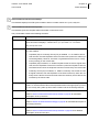
Remark
remarks or useful tips.
Caution
text to be read carefully in order to avoid damage to the device.
Warning
text to be read carefully in order to avoid injury.
DIP switch
a DIP switch or strap table.
Basic attribute
a basic attribute in the containment tree of the Telindus 1431 SHDSL
CPE.
Advanced attribute
an advanced attribute in the containment tree of the Telindus 1431
SHDSL CPE.
Structured attribute
a structured attribute within another attribute in the containment tree
of the Telindus 1431 SHDSL CPE.
Action
an action in the containment tree of the Telindus 1431 SHDSL CPE.
viii Telindus 1431 SHDSL CPE
Preface
User and reference manual
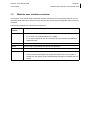
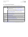
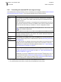
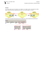
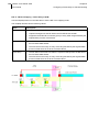
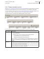
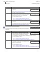
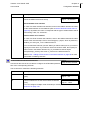
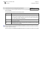
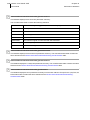
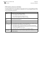
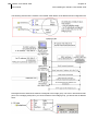
Reading a DIP switch table
At several places in this manual DIP switch tables are shown. To enable you to read such a table in a
correct manner it is explained below.
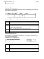
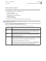
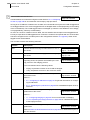
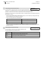
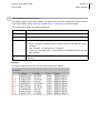
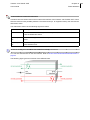
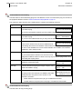
A DIP switch table has the following layout:
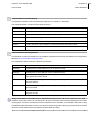
The following table explains the DIP switch configuration table layout:
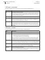
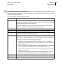
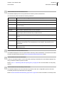
Number
This position displays …
1
the DIP switch icon.
2
the DIP switch name.
3
the DIP switch position on the DIP switch bank.
The abbreviations mean the following:
DS1 no. 1: DIP switch bank number 1, switch position number 1
4
the possible settings of the DIP switch: on and off. The default setting is printed in bold.
5
the function associated with the corresponding DIP switch setting.
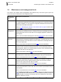
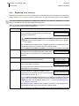
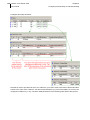
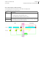
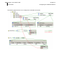
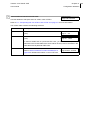
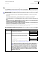
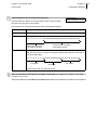
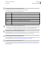
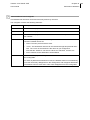
Reading an attribute string
At several places in this manual attribute strings are shown. To enable you to read such a string in a
correct manner it is explained below.
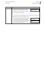
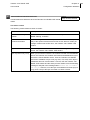
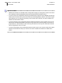
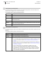
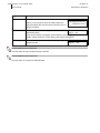
An attribute string has the following layout:
The following table explains the attribute string layout:
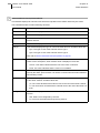
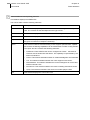
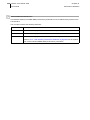
Number
This position displays …
1
the attribute icon. It indicates that the string which follows is an attribute string. Refer to
Graphical conventions on page vii for more information.
2
the attribute name and its position in the containment tree.
3
the default value of a configuration attribute.
Telindus 1431 SHDSL CPE
Preface ix
User and reference manual
TDRE version
The Telindus Dynamic Routing Engine (TDRE) is a feature-rich operating system that guarantees a common feature set across the different Telindus product lines and a uniform support by maintenance and
management tools.
This manual describes the features, containment tree and attributes of the TDRE version 11.5.
Audience
This manual is intended for computer-literate people, who have a working knowledge of computing and
networking principles.
Your feedback
Your satisfaction about this purchase is an extremely important priority to all of us at Telindus. Accordingly, all electronic, functional and cosmetic aspects of this new unit have been carefully and thoroughly
tested and inspected. If any fault is found with this unit or should you have any other quality-related comment concerning this delivery, please submit the Quality Comment Form on our web page at
www.telindusproducts.com/quality.
x Telindus 1431 SHDSL CPE
Table of contents
User and reference manual
Table of contents
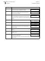
User manual............................................................................................ 1
1
Introducing the Telindus 1431 SHDSL CPE ......................................................3
1.1
1.2
1.3
1.4
1.5
2
Installing and connecting the Telindus 1431 SHDSL CPE.............................11
2.1
2.2
2.3
2.4
2.5
2.6
2.7
3
The Telindus 1431 SHDSL CPE motherboard......................................................... 30
DIP switches of the Telindus 1431 SHDSL CPE...................................................... 31
Straps of the Telindus 1431 SHDSL CPE ................................................................ 32
Opening and closing the housing ............................................................................. 33
Maintaining the Telindus 1431 SHDSL CPE ....................................................35
4.1
4.2
4.3
4.4
4.5
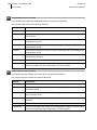
5
Safety instructions .................................................................................................... 12
Unpacking ................................................................................................................ 13
Selecting a site ......................................................................................................... 14
Mounting the Telindus 1431 SHDSL CPE to a wall ................................................. 15
Connection precautions............................................................................................ 17
Connecting the Telindus 1431 SHDSL CPE ............................................................ 18
The front panel LED indicators................................................................................. 24
DIP switches of the Telindus 1431 SHDSL CPE..............................................29
3.1
3.2
3.3
3.4
4
What is the Telindus 1431 SHDSL CPE? .................................................................. 4
Telindus 1431 SHDSL CPE applications ................................................................... 5
Modular user interface overview ................................................................................ 7
Maintenance and management tools ......................................................................... 8
Maintenance and management tools connection possibilities ................................. 10
Maintaining the Telindus 1431 SHDSL CPE with TMA ............................................ 36
Introducing the management terminology ................................................................ 42
The objects in the Telindus 1431 SHDSL CPE containment tree ............................ 46
Adding an object to the containment tree................................................................. 49
Telindus 1431 SHDSL CPE attribute overview ........................................................ 54
Basic configuration ...........................................................................................55
5.1
5.2
5.3
5.4
5.5
5.6
5.7
5.8
5.9
5.10
What is an interface?................................................................................................ 56
Configuring IP addresses ......................................................................................... 57
Configuring the SHDSL line ..................................................................................... 68
Enabling EOC message exchange .......................................................................... 72
Configuring the clocking on the modular interfaces ................................................. 80
Adding CES channels on the G703 interface........................................................... 82
Configuring passwords............................................................................................. 83
Executing configuration actions................................................................................ 85
Configuring the major features of the Telindus 1431 SHDSL CPE .......................... 89
Troubleshooting the Telindus 1431 SHDSL CPE..................................................... 91
Telindus 1431 SHDSL CPE
Table of contents xi
User and reference manual
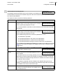
6
Configuring Frame Relay to ATM interworking ..............................................93
6.1
6.2
6.3
6.4
6.5
7
Configuring Circuit Emulation Service ..........................................................117
7.1
7.2
8
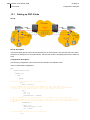
Introducing Circuit Emulation Service (CES).......................................................... 118
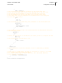
Setting up CES links............................................................................................... 119
Configuring ATM switching ............................................................................123
8.1
8.2
9
Introducing Frame Relay to ATM interworking (FRF)............................................... 94
Setting up FRF links ................................................................................................. 95
Setting up FRF.5 links in one ATM PVC .................................................................. 99
Transporting LMI over ATM in case of FRF.5 ........................................................ 101
Configuring traffic mapping .................................................................................... 103
Introducing ATM switching ..................................................................................... 124
Setting up ATM switch links ................................................................................... 125
Configuring the encapsulation protocols......................................................127
9.1
9.2
9.3
9.4
9.5
Configuring ATM encapsulation ............................................................................. 128
Configuring Frame Relay encapsulation ................................................................ 156
Configuring CES encapsulation ............................................................................. 164
Configuring PPP encapsulation (in case of PPPo…) ............................................. 167
Bandwidth control on Telindus 1431 SHDSL CPE................................................. 183
10 Configuring routing .........................................................................................187
10.1
10.2
10.3
10.4
10.5
10.6
10.7
10.8
10.9
Introducing routing.................................................................................................. 188
Enabling routing on an interface............................................................................. 189
Configuring static routes......................................................................................... 190
Configuring policy based routing ............................................................................ 198
Configuring RIP ...................................................................................................... 203
Configuring OSPF .................................................................................................. 211
Configuring address translation.............................................................................. 220
Configuring traffic and priority policy on the router................................................. 238
Configuring VRRP .................................................................................................. 253
11 Configuring bridging .......................................................................................261
11.1 Introducing bridging................................................................................................ 262
11.2 Configuring bridging ............................................................................................... 272
11.3 Configuring traffic and priority policy on the bridge ................................................ 283
12 Configuring the additional features ...............................................................287
12.1
12.2
12.3
12.4
12.5
12.6
12.7
Configuring DHCP.................................................................................................. 288
Configuring the access restrictions ........................................................................ 294
Configuring VLANs................................................................................................. 306
Configuring L2TP tunnels....................................................................................... 316
Configuring IP security ........................................................................................... 326
Configuring RADIUS .............................................................................................. 332
Configuring QoS..................................................................................................... 342
xii Telindus 1431 SHDSL CPE
Table of contents
User and reference manual
13 Configuration examples ..................................................................................353
13.1
13.2
13.3
13.4
Setting up FRF.5 links ............................................................................................ 354
Setting up FRF.8 links ............................................................................................ 356
Setting up combined CES E1 and IP services ....................................................... 358
Setting up ATM over E1 ......................................................................................... 375
Reference manual .............................................................................. 377
14 Configuration attributes ..................................................................................379
14.1 Configuration attribute overview............................................................................. 380
14.2 General configuration attributes ............................................................................. 386
14.3 LAN interface configuration attributes .................................................................... 392
14.4 WAN interface configuration attributes................................................................... 401
14.5 Encapsulation configuration attributes ................................................................... 404
14.6 SHDSL line configuration attributes ....................................................................... 443
14.7 End configuration attributes.................................................................................... 453
14.8 Modular user interface configuration attributes ...................................................... 455
14.9 Router configuration attributes ............................................................................... 468
14.10Bridge configuration attributes................................................................................ 536
14.11SNMP configuration attributes................................................................................ 553
14.12Management configuration attributes ..................................................................... 555
15 Status attributes ..............................................................................................567
15.1 Status attribute overview ........................................................................................ 568
15.2 General status attributes ........................................................................................ 574
15.3 LAN interface status attributes ............................................................................... 578
15.4 WAN interface status attributes.............................................................................. 586
15.5 Encapsulation status attributes .............................................................................. 589
15.6 SHDSL line status attributes .................................................................................. 610
15.7 End status attributes............................................................................................... 618
15.8 Modular user interface status attributes ................................................................. 621
15.9 Router status attributes .......................................................................................... 630
15.10Bridge status attributes........................................................................................... 668
15.11Management status attributes ................................................................................ 675
15.12File system status attributes................................................................................... 680
15.13Operating system status attributes......................................................................... 683
Telindus 1431 SHDSL CPE
Table of contents xiii
User and reference manual
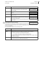
16 Performance attributes ...................................................................................685
16.1 Performance attributes overview............................................................................ 686
16.2 General performance attributes.............................................................................. 692
16.3 LAN interface performance attributes..................................................................... 694
16.4 WAN interface performance attributes ................................................................... 699
16.5 Encapsulation performance attributes.................................................................... 700
16.6 SHDSL line performance attributes........................................................................ 712
16.7 End performance attributes .................................................................................... 716
16.8 Modular user interface performance attributes....................................................... 717
16.9 Router performance attributes................................................................................ 723
16.10Bridge performance attributes ................................................................................ 740
16.11Management performance attributes ..................................................................... 746
16.12Operating system performance attributes .............................................................. 749
17 Alarm attributes ...............................................................................................753
17.1 Alarm attributes overview ....................................................................................... 754
17.2 Introducing the alarm attributes.............................................................................. 756
17.3 General alarms....................................................................................................... 759
17.4 LAN interface alarms.............................................................................................. 761
17.5 WAN interface alarms ............................................................................................ 762
17.6 SHDSL line alarms ................................................................................................. 763
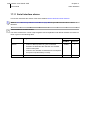
17.7 SHDSL line pair alarms .......................................................................................... 764
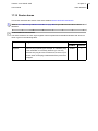
17.8 End alarms ............................................................................................................. 766
17.9 G703 interface alarms ............................................................................................ 768
17.10G703 channel alarms ............................................................................................. 769
17.11Serial interface alarms............................................................................................ 770
17.12Router alarms......................................................................................................... 771
18 TMA sub-system picture .................................................................................773
19 Auto installing the Telindus 1431 SHDSL CPE .............................................775
19.1
19.2
19.3
19.4
19.5
Introducing the auto-install protocols...................................................................... 776
Auto-install on the LAN interface............................................................................ 778
Auto-install on the WAN interface .......................................................................... 783
Creating a configuration file.................................................................................... 789
Restoring a configuration file.................................................................................. 796
20 Downloading software ....................................................................................801
20.1
20.2
20.3
20.4
20.5
20.6
20.7
What is boot, loader and application software?...................................................... 802
Downloading application software using TMA........................................................ 804
Downloading application software using TFTP ...................................................... 805
Downloading application or loader software using TML......................................... 806
Downloading application software using FTP ........................................................ 807
Downloading application or loader software in loader mode.................................. 808
Downloading files to the file system ....................................................................... 809
xiv Telindus 1431 SHDSL CPE
Table of contents
User and reference manual
21 Technical specifications .................................................................................811
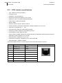
21.1 SHDSL line specifications ...................................................................................... 812
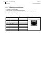
21.2 G703 interface specifications ................................................................................. 814
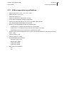
21.3 Serial interface specifications................................................................................. 815
21.4 LAN interface specifications ................................................................................... 816
21.5 Control connector specifications ............................................................................ 817
21.6 IP address assignment and auto-provisioning ....................................................... 818
21.7 FRF specifications.................................................................................................. 818
21.8 CES specifications ................................................................................................. 818
21.9 ATM encapsulation specifications .......................................................................... 819
21.10Frame Relay encapsulation specifications ............................................................. 820
21.11PPP encapsulation specifications .......................................................................... 820
21.12Other WAN encapsulation specifications ............................................................... 820
21.13IP routing specifications ......................................................................................... 821
21.14Bridging specifications............................................................................................ 823
21.15Network address translation specifications ............................................................ 824
21.16Tunnelling and VPN specifications......................................................................... 825
21.17Priority and traffic policy specifications................................................................... 826
21.18Routing and bridging performance specifications .................................................. 828
21.19Access security specifications................................................................................ 829
21.20Maintenance and management specifications ....................................................... 829
21.21Memory specifications............................................................................................ 830
21.22Power requirements ............................................................................................... 830
21.23Dimensions............................................................................................................. 830
21.24Safety compliance .................................................................................................. 831
21.25Over-voltage and over-current protection compliance ........................................... 831
21.26EMC compliance .................................................................................................... 831
21.27Environmental compliance ..................................................................................... 831
Annex .................................................................................................. 833
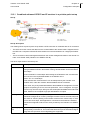
Annex A:common TCP and UDP numbers ..........................................................835
Annex B:product information ...............................................................................837
Index .................................................................................................... 839
Telindus 1431 SHDSL CPE 1
User manual
User manual
2 Telindus 1431 SHDSL CPE
User manual
Telindus 1431 SHDSL CPE
User manual
1
Chapter 1 3
Introducing the Telindus 1431 SHDSL CPE
Introducing the Telindus 1431 SHDSL CPE
This chapter gives an introduction to the Telindus 1431 SHDSL CPE. The following gives an overview
of this chapter:
•
1.1 - What is the Telindus 1431 SHDSL CPE? on page 4
•
1.2 - Telindus 1431 SHDSL CPE applications on page 5
•
1.3 - Modular user interface overview on page 7
•
1.4 - Maintenance and management tools on page 8
•
1.5 - Maintenance and management tools connection possibilities on page 10
4 Telindus 1431 SHDSL CPE
User manual
1.1
Chapter 1
Introducing the Telindus 1431 SHDSL CPE
What is the Telindus 1431 SHDSL CPE?
The Telindus 1431 SHDSL CPE uses state-of-the-art SHDSL modulation to deliver leased line, Frame
Relay and ATM services over an ATM based DSLAM access network.
For this purpose the unit can accept an exchangeable serial or G.703 interface. The equipment additionally features a fixed Ethernet auto-sense 10/100 Base-T connection for the delivery of professional IP
services.
The Telindus 1431 SHDSL CPE uses symmetrical full-duplex transmission up to 2.3 or 4.6 Mbps over a
single or dual two-wire unconditioned unshielded twisted-pair cable. The line speed can be adapted to
optimise the throughput as a function of the characteristics of the local loop. The equipment is based on
the ITU-T G.991.2 SHDSL recommendation, which guarantees spectral compatibility with legacy and
ADSL transmission systems in the same cable bundle.
The Frame Relay service is encapsulated in ATM using the Frame Relay forum recommendations FRF
5 or FRF 8. The leased line service is emulated using the ATM Circuit Emulation Service (CES). The
ATM Service delivery on E1 (G.703) is accomplished according to the ITU-T standard I 432.3. As a
result, the equipment enables service providers to deliver professional Frame-Relay, Clear channel, and
ATM services based on a standard ATM DSLAM based network.
Fully supported by the TDRE (Telindus Dynamic Routing Engine), the unit supports also differentiated
IP services including VPNs (Virtual Private Networks) and the delivery of application dependent QoS
(Quality of Service) connections.
In addition to connections to DSLAMs, the Telindus 1431 SHDSL CPE can also be used in a point-topoint configuration. In this case, the CES functionality, combined with the built-in router allow the simultaneous transport of clear channel and Ethernet based services.
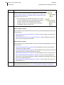
The equipment supports different management interfaces on different levels of the network. At the local
level it is possible to manage the equipment over a management console interface by means of a PC
maintenance tool, a command line interface or a menu driven interface. On IP level the equipment supports Telnet, SNMP, HTTP or TFTP/FTP. In this way it is possible to integrate the unit in any existing
network management environment. At the network level it is possible to manage the access network with
a stand-alone element manager or with an element manager integrated into HP OpenView.
Telindus 1431 SHDSL CPE
User manual
1.2
Chapter 1 5
Introducing the Telindus 1431 SHDSL CPE
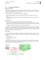
Telindus 1431 SHDSL CPE applications
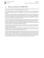
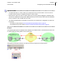
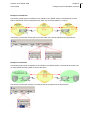
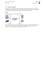
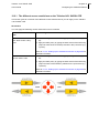
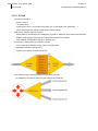
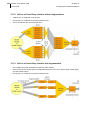
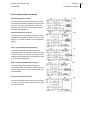
Below some examples of Telindus Router applications are shown.
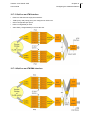
Combined IP and Leased Line service on an ATM broadband network
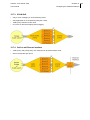
Combined IP and Leased Line service in a point-to-point set-up
6 Telindus 1431 SHDSL CPE
User manual
Chapter 1
Introducing the Telindus 1431 SHDSL CPE
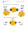
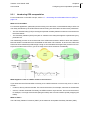
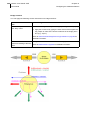
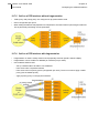
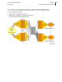
Combined IP and Frame Relay service on an ATM broadband network
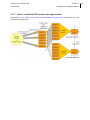
UMTS base-station connectivity based on ATM E1 connections
Telindus 1431 SHDSL CPE
User manual
1.3
Chapter 1 7
Introducing the Telindus 1431 SHDSL CPE
Modular user interface overview
The Telindus 1431 SHDSL CPE is designed to deliver leased line and Frame Relay services over an
ATM based DSLAM access network. For this purpose the unit accepts exchangeable serial and G.703
interfaces.
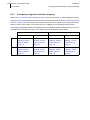
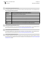
The following modular user interfaces are supported:
Modular user
interface
Supported user and line speeds
V35
V.35 is only specified up to 2 Mbps. V35 interfaces with PCB revision …·
•
0.2 or lower only support speeds up to 2 Mbps.
•
0.3 or higher support all user and corresponding line speeds, provided short
cables are used.
V36
All user and corresponding line speeds are supported.
RS530
All user and corresponding line speeds are supported.
X21
All user and corresponding line speeds are supported.
G703
•
Unframed mode: fixed 2 Mbps user and line speed.
•
Framed mode: fixed 2 Mbps user speed (time slots have to be configured
instead of a user speed). All line speeds between 64 kbps and 2 Mbps are supported.
8 Telindus 1431 SHDSL CPE
User manual
1.4
Chapter 1
Introducing the Telindus 1431 SHDSL CPE
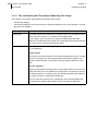
Maintenance and management tools
The Telindus 1431 SHDSL CPE is manageable in many different ways. This section gives a quick overview of the various maintenance and management tools.
Maintenance or
management
tool
Description and reference
TMA
TMA (Telindus Maintenance Application) is a free Windows software package with
a comprehensive graphical user interface that enables you to control the Telindus
products completely. I.e. to access their configuration attributes and look at status,
performance and alarm information.
Refer to 4 - Maintaining the Telindus 1431 SHDSL CPE on page 35 and the TMA
manual (PDF) for more information.
TMA Element
Management
TMA Element Management is a management application designed to monitor
large numbers of Telindus devices. It combines the easy to use graphical interface
of the stand-alone version of TMA with an event-logging application called the Element Viewer.
Refer to the TMA Element Management manual (PDF/CHM) for more information.
TMA for HP
OpenView
TMA for HP OpenView is the management application that runs on the widely
spread network management platform HP OpenView. It combines the easy to use
graphical interface of the stand-alone version of TMA with the advantages and features of HP OpenView.
Refer to the TMA for HP OpenView manual (PDF) for more information.
TMA CLI
TMA CLI (TMA Command Line Interface) enables you to use its commands in
scripts in order to automate management actions. This is particularly useful in
large networks. TMA CLI is a complementary product to TMA, TMA Element Management and TMA for HP OpenView.
Refer to the TMA CLI manual (PDF) for more information.
ATWIN
ATWIN is a menu-driven user interface. You can read and change all attributes as
with TMA, but in a more basic, textual representation using a VT100 terminal.
Refer to the Maintenance tools manual (PDF) for more information.
CLI
CLI is also a Command Line Interface, although not so extensive as TMA CLI.
Experienced users who are familiar with the syntax can access the Telindus
devices more quickly than with TMA or ATWIN.
Refer to the Maintenance tools manual (PDF) for more information.
Web Interface
The Web Interface is an ATWIN alike menu-driven user interface. You can read
and change all attributes as with TMA, but in a more basic representation using a
web browser.
Refer to the Maintenance tools manual (PDF) for more information.
Note that the HTTP interfaces are not only available on port 80, but also on
port 8080. This allows connecting to the HTTP interfaces in case a NAT
service is defined on port 80.
Telindus 1431 SHDSL CPE
User manual
Chapter 1 9
Introducing the Telindus 1431 SHDSL CPE
Maintenance or
management
tool
Description and reference
SNMP
You can manage the Telindus 1431 SHDSL CPE through SNMP using any SNMP
browser. The Telindus 1431 SHDSL CPE supports MIB2 and a private MIB, including traps.
The private MIB comes with your copy of TMA. After installation of the TMA data
files, the private MIB file is available in directory C:\Program Files\TMA\snmp1 with
the name <filename>.mib2.
Refer to 14.11 - SNMP configuration attributes on page 553 and the documentation of your SNMP browser for more information.
Easy Configurator
The Easy Configurator allows you to add HTML pages on top of the standard Web
Interface by adding a set of specific files on the file system of the Telindus 1431
SHDSL CPE. These files can be made either by Telindus or by the customer itself.
The goal is to offer a simple, custom made web interface which allows only to
change or show those parameters that are relevant for a certain application or customer.
Refer to the Maintenance tools manual (PDF) for more information.
Note that the HTTP interfaces are not only available on port 80, but also on
port 8080. This allows connecting to the HTTP interfaces in case a NAT
service is defined on port 80.
1. The first part of the directory path may be different if you did not choose the default path during
the installation of the TMA data files.
2. The filename is product dependent. To determine which MIB file corresponds with which product, refer to the models.nms file (located in C:\Program Files\TMA\model1).
10 Telindus 1431 SHDSL CPE
Chapter 1
User manual
1.5
Introducing the Telindus 1431 SHDSL CPE
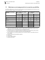
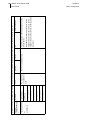
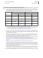
Maintenance and management tools connection possibilities
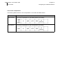
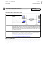
The following table gives an overview of all the maintenance and management tools and how you can
connect them with the Telindus 1431 SHDSL CPE:
Maintenance or management tool
Tool - Telindus 1431 SHDSL
CPE connection
Tool - management concentrator connection1
Serial2
Serial2
IP3
IP3
CLI
X4
X5
X4
X5
ATWIN
X4
X5
X4
X5
TMA
X
X
X
X
TMA CLI
X
X
X
X
TMA Element Management
X
X
TMA for HP OpenView
X
X
SNMP6
X
X
Web Interface7
X
X
1. Examples of management concentrators are the Orchid 1003 LAN, the Telindus 1030 Router
series, the Telindus 2300 SHDSL series, etc. Refer to their corresponding manuals for more
information on how to set these devices up as management proxy.
2. A serial connection is a connection between the COM port of your PC and the control connector of the Telindus 1431 SHDSL CPE using a male-female DB9 cable.
3. An IP connection is a connection between your PC and the Telindus 1431 SHDSL CPE over
an IP network.
4. Using a VT100 terminal (emulation program).
5. Using Telnet.
6. Using an SNMP browser.
7. Using a web browser.
Telindus 1431 SHDSL CPE
User manual
2
Chapter 2 11
Installing and connecting the Telindus 1431 SHDSL CPE
Installing and connecting the Telindus 1431 SHDSL CPE
First this chapter gives some important safety instructions. Then it explains how to install and connect
the Telindus 1431 SHDSL CPE.
You are advised to read this chapter from the beginning to the end, without skipping any part. By doing
so, your Telindus 1431 SHDSL CPE will be completely installed and ready for configuration when you
reach the end of this chapter.
The following gives an overview of this chapter:
•
2.1 - Safety instructions on page 12
•
2.2 - Unpacking on page 13
•
2.3 - Selecting a site on page 14
•
2.4 - Mounting the Telindus 1431 SHDSL CPE to a wall on page 15
•
2.5 - Connection precautions on page 17
•
2.6 - Connecting the Telindus 1431 SHDSL CPE on page 18
•
2.7 - The front panel LED indicators on page 24
12 Telindus 1431 SHDSL CPE
User manual
2.1
Chapter 2
Installing and connecting the Telindus 1431 SHDSL CPE
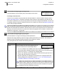
Safety instructions
IMPORTANT SAFETY INSTRUCTIONS
Disconnect the power supply before installing, adjusting or servicing the unit.
WICHTIGE SICHERHEITSINSTRUKTIONEN
Vor sämtlichen Arbeiten am Gerät (Installation, Einstellungen, Reparaturen etc.) sollten Sie den
Netzstecker aus der Steckdose ziehen.
SAFETY WARNING
To avoid damage to the unit, please observe all procedures described in this chapter.
SICHERHEITSBESTIMMUNGEN
Um eine Beschädigung des Gerätes zu verhindern, beachten Sie bitte unbedingt die Sicherheitsbestimmungen die in diesem Abschnitt beschrieben werden.
Ensure that the unit and its connected equipment all use the same power and ground, to reduce noise
interference and possible safety hazards caused by differences in ground or earth potentials.
Telindus 1431 SHDSL CPE
User manual
2.2
Chapter 2 13
Installing and connecting the Telindus 1431 SHDSL CPE
Unpacking
Checking the shipping carton
Rough handling during shipping causes most early failures. Before installation, check the shipping carton for signs of damage:
•
If the shipping carton is damaged, please place a claim with the carrier company immediately.
•
If the shipping carton is undamaged, do not dispose of it in case you need to store the unit or ship it
in the future.
Package contents
The box should contain the following items:
•
Telindus 1431 SHDSL CPE
•
48 Vdc power supply plug
•
TMA CD-ROM (including this User and Reference manual in PDF format)
Optionally (depending which sales item you ordered):
•
external power supply with power cord
14 Telindus 1431 SHDSL CPE
User manual
2.3
Chapter 2
Installing and connecting the Telindus 1431 SHDSL CPE
Selecting a site
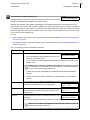
WARNING
Always place the unit on its feet without blocking the air vents.
Do not stack multiple units directly onto each other, as stacking can cause heat build-up that could damage the equipment.
ACHTUNG
Stellen Sie das Gerät niemals seitlich, sondern nur auf den Füßen auf und achten Sie darauf, daß die
Lüftungsschlitze an der Seitenverkleidung frei bleiben.
Stapeln Sie nicht mehrere Geräte direkt übereinander, dies kann zu einem Hitzestau führen.
Install the unit in an area free of extreme temperatures, humidity, shock and vibration. Position it so that
you can easily see and access the front panel and its control indicators. Leave enough clearance at the
back for cables and wires. Position the unit within the correct distances for the different accesses and
within 2m of a power outlet.
Telindus 1431 SHDSL CPE
User manual
2.4
Chapter 2 15
Installing and connecting the Telindus 1431 SHDSL CPE
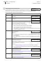
Mounting the Telindus 1431 SHDSL CPE to a wall
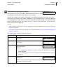
The Telindus 1431 SHDSL CPE can be mounted to the wall. In order to do so, proceed as follows:
Step
1
Action
Drill two holes in the wall, according to the following specifications:
•
hole diameter: 4 mm
•
distance between the holes:
•
2
-
in case of the PBOX05 housing: 120 mm
-
in case of the PBOX06 housing: 60 mm
hole depth: at least 25 mm
Insert two wall plugs in the holes. The plugs should have the following dimensions:
•
diameter: 4 mm
•
length: 20 mm
3
Screw two square hooks (steel zinc plated and white epox) in the plugs. The square
hooks should have the following dimensions:
4
Slide the Telindus 1431 SHDSL CPE over the hooks until it touches the wall, as shown
in the figure below.
5
Slide the Telindus 1431 SHDSL CPE down until it is firmly attached, as shown in the figure below.
16 Telindus 1431 SHDSL CPE
User manual
Chapter 2
Installing and connecting the Telindus 1431 SHDSL CPE
Telindus 1431 SHDSL CPE
User manual
2.5
Chapter 2 17
Installing and connecting the Telindus 1431 SHDSL CPE
Connection precautions
ESD WARNING
The circuit boards are sensitive to electrostatic discharges (ESD) and should be handled with care. It is
advisable to ensure an optimal electrical contact between yourself, the working area and a safety ground
before touching any circuit board. Take special care not to touch any component or connector on the
circuit board.
EMC WARNING
The Telindus access products are fully EMC compliant. To ensure compliance with EMC directive 89/
336/EEC, shielded cables or ferrite beads have to be used.
NOTE
This unit may be powered by an IT power system.
The connectors of the Telindus 1431 SHDSL CPE should only be connected to the following circuit
types:
Connector name
Connector label
Connector type
Circuit type
LAN connector
LAN
RJ45
SELV
modular user interface
connector
(none)
(depends on the type of
interface)
SELV
SHDSL line connector
LINE
RJ12
TNV-1
control connector
CTRL
subD-9
SELV
•
SELV (Safety Extra Low Voltage): local connection (e.g. PC to Telindus 1431 SHDSL CPE) or leased
line inside the building.
•
TNV-1 (Telecom Network Voltage): leased line outside the building.
•
TNV-2: PSTN from PABX inside the building.
•
TNV-3: PSTN from operator PABX outside the building.
18 Telindus 1431 SHDSL CPE
User manual
2.6
Chapter 2
Installing and connecting the Telindus 1431 SHDSL CPE
Connecting the Telindus 1431 SHDSL CPE
This section explains how to connect the Telindus 1431 SHDSL CPE. The following gives an overview
of this section:
•
2.6.1 - Rear view of the Telindus 1431 SHDSL CPE on page 19
•
2.6.2 - The different parts of the Telindus 1431 SHDSL CPE on page 20
•
2.6.3 - Connecting the Telindus 1431 SHDSL CPE - an example on page 22
Telindus 1431 SHDSL CPE
User manual
2.6.1
Chapter 2 19
Installing and connecting the Telindus 1431 SHDSL CPE
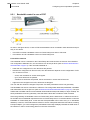
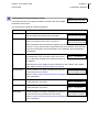
Rear view of the Telindus 1431 SHDSL CPE
The following figure shows the back panel of the Telindus 1431 SHDSL CPE:
20 Telindus 1431 SHDSL CPE
User manual
2.6.2
Chapter 2
Installing and connecting the Telindus 1431 SHDSL CPE
The different parts of the Telindus 1431 SHDSL CPE
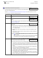
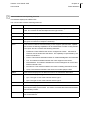
The following table gives an overview of the parts located at the back of the Telindus 1431 SHDSL CPE
and reveals their function:
Label
Function
9 VDC
This is the 9 Vdc power input. Insert the plug of the 9 Vdc external power supply in this
socket.
Important remark
Either use the 9 Vdc or use the 48 Vdc power input. Do not use them both at the
same time.
Refer to 21.22 - Power requirements on page 830 for the power specifications of the Telindus 1431 SHDSL CPE.
48V
This is the 48 Vdc power input. First wire the 48 Vdc power supply plug (delivered with
the Telindus 1431 SHDSL CPE). Then insert the plug in the 48 Vdc socket.
The + and - indications are with respect to each other, not to ground level. This means
that for a standard -48 Vdc connection, the ground has to be connected to +, while the
negative voltage has to be connected to the -. The 48 Vdc power supply plug also has an
earth connection.
Important remark
Either use the 9 Vdc or use the 48 Vdc power input. Do not use them both at the
same time.
Refer to 21.22 - Power requirements on page 830 for the power specifications of the Telindus 1431 SHDSL CPE.
LAN
This RJ45 connector is the connection towards the LAN.
Connect one side of an RJ45 to RJ45 cable (not included) to the LAN connector of the
Telindus 1431 SHDSL CPE and the other side to a network outlet. If you want to connect
the Telindus 1431 SHDSL CPE to …
•
a regular Ethernet network outlet, then use a crossed RJ45 cable.
•
an Ethernet hub, then use a straight RJ45 cable.
Refer to 21.4 - LAN interface specifications on page 816 for the specifications of this connector.
Telindus 1431 SHDSL CPE
User manual
Chapter 2 21
Installing and connecting the Telindus 1431 SHDSL CPE
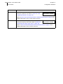
Label
Function
-
This empty slot is provided to insert the desired modular user interface without opening
the housing.
(empty
interface
slot)
To insert the modular user interface, proceed as follows:
1. Gently slide the modular user
interface on the two inner slides
into the empty slot.
2. When nearly inserted, press
tight.
3. Fasten both screws.
4. When the modular user interface has been inserted, connect the connector to the application.
CTRL
This female 9-pins subD connector is the control connector.
You can connect this connector to a COM port of your PC with a straight male-female
DB9 cable (not included). This enables you to manage the Telindus 1431 SHDSL CPE
locally, using TMA, CLI, ATWIN etc.
You can also connect this connector to a management concentrator, also for management purposes.
Refer to 21.5 - Control connector specifications on page 817 for the specifications of this
connector.
LINE
This RJ45 connector is the connection towards the SHDSL line.
Connect one side of an RJ45 to RJ45 cable (not included) to the LINE connector of the
Telindus 1431 SHDSL CPE and the other side to an SHDSL outlet.
For optimum performance, the used line pairs have to be properly twisted pairs.
Refer to 21.1 - SHDSL line specifications on page 812 for the specifications of this connector.
22 Telindus 1431 SHDSL CPE
User manual
2.6.3
Chapter 2
Installing and connecting the Telindus 1431 SHDSL CPE
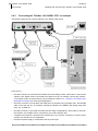
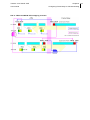
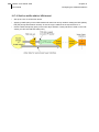
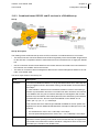
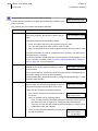
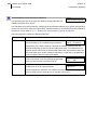
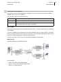
Connecting the Telindus 1431 SHDSL CPE - an example
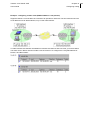
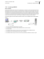
The following figure shows a typical Telindus 1431 SHDSL CPE set-up:
In this set-up …
•
the LINE connector is connected to an SHDSL line outlet using an RJ45 - RJ45 cable. In this way the
Telindus 1431 SHDSL CPE is connected to the WAN. You can, for example, connect the Telindus
1431 SHDSL CPE to a remote network over a leased line. Refer to 1.2 - Telindus 1431 SHDSL CPE
applications on page 5 for some typical applications.
•
the CTRL connector is connected to the COM port of a computer using a straight male - female DB9
cable. In this way you can, for example, manage the Telindus 1431 SHDSL CPE locally using TMA
(CLI), CLI, ATWIN, etc.
•
the LAN connector is connected to an Ethernet hub using a straight RJ45 - RJ45 cable. In this way
the Telindus 1431 SHDSL CPE is connected to your local network (LAN).
•
a modular user interface is inserted in the interface slot. You can then connect the connector of the
modular user interface to your application.
•
the external power supply is connected to the 9V power input.
Telindus 1431 SHDSL CPE
User manual
Chapter 2 23
Installing and connecting the Telindus 1431 SHDSL CPE
For optimum performance, the used line pairs have to be properly twisted pairs.
24 Telindus 1431 SHDSL CPE
User manual
2.7
Chapter 2
Installing and connecting the Telindus 1431 SHDSL CPE
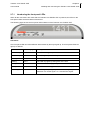
The front panel LED indicators
This section gives an overview of the front panel LEDs and what they indicate. The following gives an
overview of this section:
•
2.7.1 - Introducing the front panel LEDs on page 25
•
2.7.2 - The power LED (PWR, green) on page 26
•
2.7.3 - The line link LED (LINE LNK1 / LNK2, green) on page 26
•
2.7.4 - The line data LED (LINE ACT, green) on page 26
•
2.7.5 - The serial link LED (SERIAL LNK, green) in case of a G703 interface on page 27
•
2.7.6 - The serial data LED (SERIAL ACT, green) in case of a G703 interface on page 27
•
2.7.7 - The serial link LED (SERIAL LNK, green) in case of a serial interface on page 28
•
2.7.8 - The serial data LED (SERIAL ACT, green) in case of a serial interface on page 28
•
2.7.9 - The LAN LED (LAN ACT, green) on page 28f
Telindus 1431 SHDSL CPE
User manual
2.7.1
Chapter 2 25
Installing and connecting the Telindus 1431 SHDSL CPE
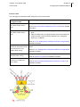
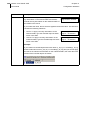
Introducing the front panel LEDs
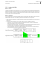
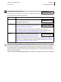
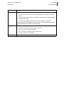
When all the connections are made and the Telindus 1431 SHDSL CPE is powered, the LEDs on the
front panel reflect the actual status of the device.
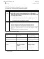
The following figure shows the front panel LED indicators of the Telindus 1431 SHDSL CPE:
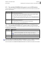
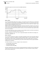
LED states
One front panel LED can reflect different status modes by the way it lights up. The front panel LEDs can
light up as follows:
LED state
LED duty cycle
Description
continuously off
0%
The LED never lights up.
continuously on
100 %
The LED lights up continuously.
blinking
50 %
The LED is as much lit as it is out.
flashing
20 %
The LED only lights up during 20% of the time.
mostly off
-
The LED occasionally lights up, without a fixed duty cycle.
mostly on
-
The LED occasionally goes out, without a fixed duty cycle.
monitoring
-
The LED lights up irregularly. For instance, it lights up on
detection of a certain signal. I.e. it monitors this signal.
26 Telindus 1431 SHDSL CPE
User manual
2.7.2
Chapter 2
Installing and connecting the Telindus 1431 SHDSL CPE
The power LED (PWR, green)
The power LED indicates the following:
LED status
Description
continuously off
No DC input power is available.
blinking
The self test, performed during the boot sequence, failed. In this condition, the
ACT LEDs are continuously on.
continuously on
The Telindus 1431 SHDSL CPE is powered and the boot sequence has been completed successfully.
In case the Telindus 1431 SHDSL CPE remains in boot mode, also the ACT LEDs
are continuously on to indicate this special state. Refer to 20.1 - What is boot,
loader and application software? on page 802 for more information on boot mode.
2.7.3
The line link LED (LINE LNK1 / LNK2, green)
This LED reflects the status of the line:
LED status
Description
continuously off
No response on the handshake. E.g. nothing is connected to the line.
blinking
The handshake is in progress.
continuously on
The handshake was successful. Layer 1 is up.
The LINE LNK2 LED is only present on a Telindus 1431 SHDSL CPE 2 pair version.
2.7.4
The line data LED (LINE ACT, green)
This LED reflects the status of the user data on the line:
LED status
Description
continuously off
Layer 2 is down.
monitoring
Layer 2 is up and user data is present (both transmit and receive data).
continuously on
Layer 2 is up, but no user data is present.
Telindus 1431 SHDSL CPE
User manual
2.7.5
Chapter 2 27
Installing and connecting the Telindus 1431 SHDSL CPE
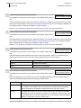
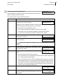
The serial link LED (SERIAL LNK, green) in case of a G703 interface
In case a modular G703 interface is inserted in the interface slot, then this LED reflects the status of the
link on the G703 interface:
LED status
Description
continuously off
In case the G703 interface is in …
continuously on
2.7.6
•
unframed mode: Loss Of Synchronisation (LOS) or Alarm Indication Signal
(AIS, also called “all ones”) is received on the interface.
•
framed mode: Loss Of Synchronisation (LOS), Loss of Frame Alignment (LFA)
or Alarm Indication Signal (AIS, also called “all ones”) is received on the interface.
In case the G703 interface is in …
•
unframed mode: no LOS or AIS is received on the interface.
•
framed mode: layer 1 (G.704 framing) is up.
The serial data LED (SERIAL ACT, green) in case of a G703 interface
In case a modular G703 interface is inserted in the interface slot, then this LED reflects the status of the
user data on the G703 interface:
LED status
Description
continuously off
Layer 2 is down.
In case of CES, the SERIAL ACT LED is always off (no layer 2).
monitoring
Layer 2 is up and user data is present (both transmit and receive data).
continuously on
Layer 2 is up, but no user data is present.
If the G703 interface has multiple logical interfaces (channelised E1), then the SERIAL ACT LED indicates only the status for the first logical interface (i.e. channel) on this physical interface.
28 Telindus 1431 SHDSL CPE
User manual
2.7.7
Chapter 2
Installing and connecting the Telindus 1431 SHDSL CPE
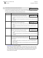
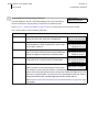
The serial link LED (SERIAL LNK, green) in case of a serial interface
In case a modular serial interface (e.g. V35, V36, X21 or RS530) is inserted in the interface slot, then
this LED reflects the status of the link on the serial interface:
LED status
Description
continuously off
The Clear To Send signal (CTS) is not present. I.e. nothing is connected to the
interface.
continuously on
The CTS signal is present.
2.7.8
The serial data LED (SERIAL ACT, green) in case of a serial interface
In case a modular serial interface (e.g. V35, V36, X21 or RS530) is inserted in the interface slot, then
this LED reflects the status of the user data on the serial interface:
LED status
Description
continuously off
Layer 2 is down.
In case of CES, the SERIAL ACT LED is always off (no layer 2).
monitoring
Layer 2 is up and user data is present (both transmit and receive data).
continuously on
Layer 2 is up, but no user data is present.
2.7.9
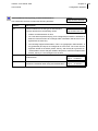
The LAN LED (LAN ACT, green)
This LED reflects the status of the link and monitors the user data on the LAN interface:
LED status
Description
continuously off
Nothing is connected to the LAN interface.
monitoring
The Ethernet link is up and there is network activity on the LAN.
continuously on
The Ethernet link is up, but there is no network activity on the LAN.
Telindus 1431 SHDSL CPE
User manual
3
Chapter 3 29
DIP switches of the Telindus 1431 SHDSL CPE
DIP switches of the Telindus 1431 SHDSL CPE
This chapter locates the DIP switches on the Telindus 1431 SHDSL CPE motherboard. It gives an overview of their function and it explains how to change their settings.
The following gives an overview of this chapter:
•
3.1 - The Telindus 1431 SHDSL CPE motherboard on page 30
•
3.2 - DIP switches of the Telindus 1431 SHDSL CPE on page 31
•
3.3 - Straps of the Telindus 1431 SHDSL CPE on page 32
•
3.4 - Opening and closing the housing on page 33
Default settings are printed in bold.
30 Telindus 1431 SHDSL CPE
User manual
3.1
Chapter 3
DIP switches of the Telindus 1431 SHDSL CPE
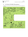
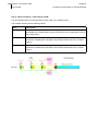
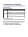
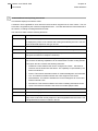
The Telindus 1431 SHDSL CPE motherboard
The figure below shows the position of the DIP switches and straps on the Telindus 1431 SHDSL CPE
motherboard:
Telindus 1431 SHDSL CPE
Chapter 3 31
User manual
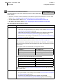
3.2
DIP switches of the Telindus 1431 SHDSL CPE
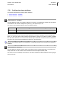
DIP switches of the Telindus 1431 SHDSL CPE
Refer to 3.4 - Opening and closing the housing on page 33 to find out how to open the housing in order
to change the DIP switch settings.
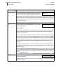
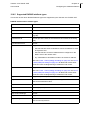
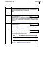
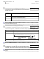
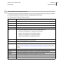
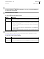
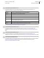
The following table gives an overview of the DIP switches on DIP switch bank DS1:
DIP switch name
loader mode
DS1 no.
1
Setting
Function
on
Normal operation.
off
Start up in loader mode.
Refer to 20.6 - Downloading application
or loader software in loader mode on
page 808.
load default
configuration
2
on
Normal operation.
off
Load default configuration.
Refer to 5.8.4 - Loading the default configuration using a DIP switch on
page 87.
32 Telindus 1431 SHDSL CPE
User manual
3.3
Chapter 3
DIP switches of the Telindus 1431 SHDSL CPE
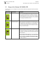
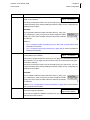
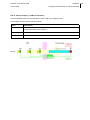
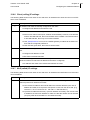
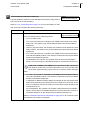
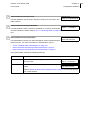
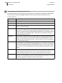
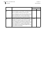
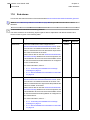
Straps of the Telindus 1431 SHDSL CPE
Using strap ST4, you can configure the interconnection between the signal ground and the protective
ground (earth):
Strap settings
Connection
Description
position 1
disconnected
By default, the signal ground is disconnected from the
earth. This avoids problems which might occur when the
earth potential of the Telindus 1431 SHDSL CPE and the
connected application is not the same. In such a situation
earth current loops may induce distortion on the transmitted
data, resulting in transmission errors.
position 2
connected through
100 ohms resistor
Sometimes you might want to connect the Telindus 1431
SHDSL CPE earth to the application earth although both
earth potentials are not the same. (E.g. to avoid a big difference between both earth potentials.) To avoid that high
earth currents are generated, you can make this connection
through a 100 ohms resistor.
position 3
directly connected
Sometimes it is not possible to connect the application
directly to the earth. In that case you can earth the application through the Telindus 1431 SHDSL CPE by connecting
the Telindus 1431 SHDSL CPE to the earth and setting the
strap in position 3.
Also the opposite situation might occur: it is not possible to
earth the Telindus 1431 SHDSL CPE. In that case you can
earth the Telindus 1431 SHDSL CPE through the application by connecting the application to the earth and setting
the strap in position 3.
Telindus 1431 SHDSL CPE
User manual
3.4
Chapter 3 33
DIP switches of the Telindus 1431 SHDSL CPE
Opening and closing the housing
When you want to change the DIP switch settings of the Telindus 1431 SHDSL CPE, you have to open
and close the housing of the Telindus 1431 SHDSL CPE. This section explains how to do so.
Opening the housing
To open the housing of the Telindus 1431 SHDSL CPE, proceed as follows:
Step
Action
1
Disconnect the external power supply.
2
Unscrew the two screws located at the back of the
housing.
3
Remove the cover as follows:
1. Carefully lift the back of the cover a
few centimetres.
2. Gently pull the cover backwards
from under the nose of the housing.
Closing the housing
To close the housing of the Telindus 1431 SHDSL CPE, proceed as follows:
Step
1
Action
Replace the cover as follows:
1. Gently push the cover under the
nose of the housing.
2. Lower the back of the cover.
3. Push the back of the cover down,
clicking cover and bottom together.
2
Fasten the two screws located at the back of the
housing.
3
Reconnect the external power supply.
34 Telindus 1431 SHDSL CPE
User manual
Chapter 3
DIP switches of the Telindus 1431 SHDSL CPE
Telindus 1431 SHDSL CPE
User manual
4
Chapter 4 35
Maintaining the Telindus 1431 SHDSL CPE
Maintaining the Telindus 1431 SHDSL CPE
Once you installed the Telindus 1431 SHDSL CPE, you can proceed with the configuration of the Telindus 1431 SHDSL CPE. You can do this using any of the maintenance or management tools introduced
in 1.4 - Maintenance and management tools on page 8.
This chapter briefly highlights one of those tools: the Telindus Maintenance Application (TMA). It introduces TMA and describes how to start a session on the Telindus 1431 SHDSL CPE. It also introduces
the terminology concerning the management of a Telindus device. Furthermore, it explains why and how
to add an object to the containment tree.
The following gives an overview of this chapter:
•
4.1 - Maintaining the Telindus 1431 SHDSL CPE with TMA on page 36
•
4.2 - Introducing the management terminology on page 42
•
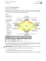
4.3 - The objects in the Telindus 1431 SHDSL CPE containment tree on page 46
•
4.4 - Adding an object to the containment tree on page 49
•
4.5 - Telindus 1431 SHDSL CPE attribute overview on page 54
36 Telindus 1431 SHDSL CPE
User manual
4.1
Chapter 4
Maintaining the Telindus 1431 SHDSL CPE
Maintaining the Telindus 1431 SHDSL CPE with TMA
First, this section introduces TMA. Then it describes how to start a session on the Telindus 1431 SHDSL
CPE. The following gives an overview of this section:
•
4.1.1 - What is TMA? on page 37
•
4.1.2 - How to connect TMA? on page 37
•
4.1.3 - Connecting with TMA through the control connector on page 38
•
4.1.4 - Connecting with TMA over an IP network on page 40
Telindus 1431 SHDSL CPE
User manual
4.1.1
Chapter 4 37
Maintaining the Telindus 1431 SHDSL CPE
What is TMA?
TMA is the acronym for Telindus Maintenance Application. TMA is a free Windows software package
that enables you to maintain the Telindus 1431 SHDSL CPE, i.e. to access its configuration attributes
and look at status, performance and alarm information using a user friendly graphical user interface.
TMA is an excellent tool for complete control of the Telindus access devices. When using TMA in combination with a network management system such as HP OpenView, complete networks can be managed from one central site.
Consult the TMA manual (PDF) to find out how to install TMA and to get acquainted with the user interface.
You will need a new version of the model file distribution if changes have been made to the attributes of
the Telindus 1431 SHDSL CPE. The most recent model files and TMA engine can always be downloaded from the Telindus web site at www.telindusproducts.com/TMA.
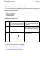
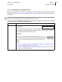
4.1.2
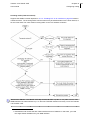
How to connect TMA?
There are two ways to establish a connection between the computer running TMA and the Telindus 1431
SHDSL CPE:
•
through a serial connection, i.e. through the control connector of the Telindus 1431 SHDSL CPE.
Refer to 4.1.3 - Connecting with TMA through the control connector on page 38.
•
through an IP connection, i.e. through the LAN connector of the Telindus 1431 SHDSL CPE. Refer
to 4.1.4 - Connecting with TMA over an IP network on page 40.
38 Telindus 1431 SHDSL CPE
User manual
4.1.3
Chapter 4
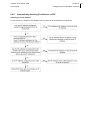
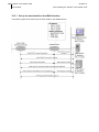
Maintaining the Telindus 1431 SHDSL CPE
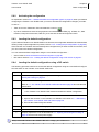
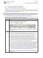
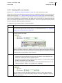
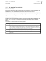
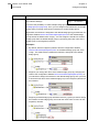
Connecting with TMA through the control connector
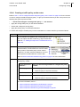
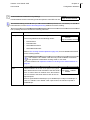
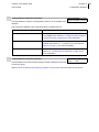
To established a connection between TMA and the Telindus 1431 SHDSL CPE through the control connector, proceed as follows:
Step
Action
1
Connect a serial port of your computer (e.g. COM1) through a
straight DB9 male - female cable
with the control connector of the
Telindus 1431 SHDSL CPE.
2
Start TMA.
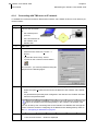
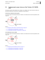
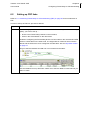
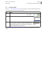
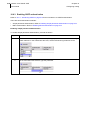
3
In the TMA window, either …
•
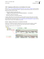
select from the menu bar: Connect →
Device…
•
or press the short-cut key: Ctrl+N
•
or click on the Connect to device button:
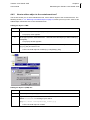
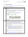
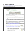
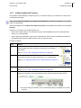
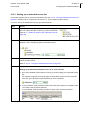
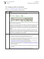
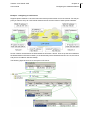
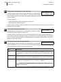
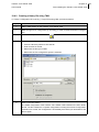
The Connect… (to a device) window is displayed
as in the following figure:
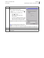
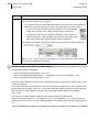
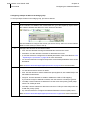
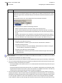
4
5
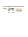
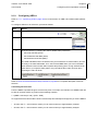
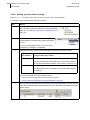
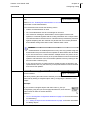
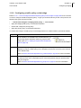
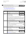
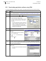
In the Connect… (to a device) window, specify the following:
•
Select the option Serial and specify the COM port of your computer to which the Telindus 1431 SHDSL CPE is connected.
•
If previously a password has been configured in the Telindus 1431 SHDSL CPE then
also fill in the password field.
Click on the Next > button.
⇒The second Connect… window is displayed.
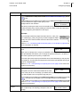
Telindus 1431 SHDSL CPE
User manual
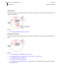
Step
6
Chapter 4 39
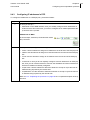
Maintaining the Telindus 1431 SHDSL CPE
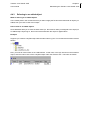
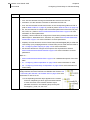
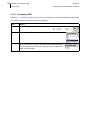
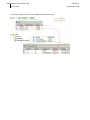
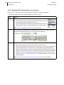
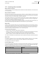
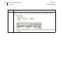
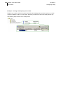
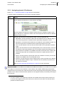
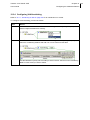
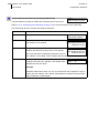
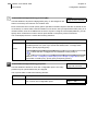
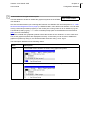
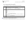
Action
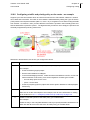
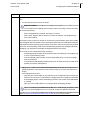
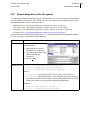
In the Connect… (select a device) window, proceed as follows to connect to the …
•
local Telindus 1431 SHDSL CPE: select On
device.
•
remote Telindus 1431 SHDSL CPE:
-
Select After device.
-
Enter 1 in the NMS address field.
-
Select Relative.
-
If previously a password has been configured in the remote Telindus 1431 SHDSL
CPE then also fill in the password field.
You can only connect to a remote Telindus 1431 SHDSL CPE if the data link is up.
7
Click on the Finish button.
8
After a couple of seconds, the attributes of the Telindus 1431 SHDSL CPE appear in the
TMA window.
40 Telindus 1431 SHDSL CPE
User manual
4.1.4
Chapter 4
Maintaining the Telindus 1431 SHDSL CPE
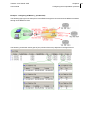
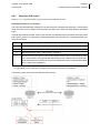
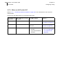
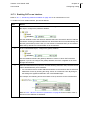
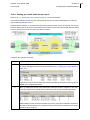
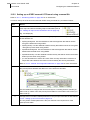
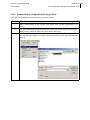
Connecting with TMA over an IP network
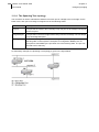
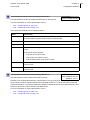
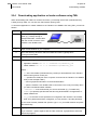
To established a connection between TMA and the Telindus 1431 SHDSL CPE over an IP network, proceed as follows:
Step
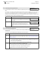
1
Action
Connect the IP network
to …
•
the network port of
your PC,
•
the LAN connector of
the Telindus 1431
SHDSL CPE.
2
Start TMA.
3
In the TMA window, either …
•
select from the menu bar: Connect →
Device…
•
or press the short-cut key: Ctrl+N
•
or press on the Connect to device button:
The Connect… (to a device) window is being displayed as in the following figure:
4
In the Connect… (to a device) window, specify the following:
•
Select the option IP address and enter the IP address of the Telindus 1431 SHDSL
CPE.
•
If a password has previously been configured in the Telindus 1431 SHDSL CPE then
also fill in the password field.
Before you are able to establish a connection over an IP network, you have to configure an IP address and a default gateway in the Telindus 1431 SHDSL CPE.
You can do this by first connecting TMA to the Telindus 1431 SHDSL CPE through the
control connector, and then configuring an IP address and a default gateway. Refer to
the 5.2 - Configuring IP addresses on page 57.
5
Click on the Next > button.
⇒The second Connect… window is displayed.
Telindus 1431 SHDSL CPE
User manual
Step
6
Chapter 4 41
Maintaining the Telindus 1431 SHDSL CPE
Action
In the Connect… (select a device) window, proceed as follows to connect to the …
•
local Telindus 1431 SHDSL CPE: select On
device.
•
remote Telindus 1431 SHDSL CPE:
-
Select After device.
-
Enter 1 in the NMS address field.
-
Select Relative.
-
If previously a password has been configured in the remote Telindus 1431 SHDSL
CPE then also fill in the password field.
You can only connect to a remote Telindus 1431 SHDSL CPE if the data link is up.
7
Click on the Finish button.
8
After a couple of seconds, the attributes of the Telindus 1431 SHDSL CPE appear in the
TMA window.
42 Telindus 1431 SHDSL CPE
User manual
4.2
Chapter 4
Maintaining the Telindus 1431 SHDSL CPE
Introducing the management terminology
This section briefly introduces the terminology concerning the management of a Telindus device. It
explains terms such as containment tree, group, object, attribute, value and action.
The following gives an overview of this section:
•
4.2.1 - Graphical representation of the containment tree on page 43
•
4.2.2 - Containment tree terminology on page 44
Telindus 1431 SHDSL CPE
User manual
4.2.1
Chapter 4 43
Maintaining the Telindus 1431 SHDSL CPE
Graphical representation of the containment tree
The most comprehensible graphical representation of the containment tree is given in TMA. The following figure depicts the TMA window displaying a containment tree:
Refer to 4.2.2 - Containment tree terminology on page 44 for an explanation of the terms associated with
the containment tree.
44 Telindus 1431 SHDSL CPE
User manual
4.2.2
Chapter 4
Maintaining the Telindus 1431 SHDSL CPE
Containment tree terminology
Refer to 4.2.1 - Graphical representation of the containment tree on page 43 for a figure of a containment
tree.
The following table explains the terminology associated with the containment tree:
Term
Description
containment tree
The containment tree represents the hierarchical structure of the Telindus 1431
SHDSL CPE. It is composed of a number of objects that are ordered in a tree. This
tree resembles a Windows directory structure:
•
it is also a levelled structure, with nodes which can be expanded or reduced.
•
the containment tree objects can be compared with file folders.
•
the objects contain attributes like file folders contain files.
object
An object represents a physical interface, an application or a combination of both.
Each object has its own set of attributes.
parent and child
object
Some objects are not present in the containment tree by default. If you want to use
the features associated with such an object, then you have to add the object first.
You always add an object under another object. The object you add is called the
child object. The object under which you add this child object is called the parent
object.
Objects which you can add are also often referred to as user-instantiatable objects.
index name
Of some objects more than one object is present in the containment tree. The different objects are distinguished from one another by adding an index. E.g. linePair[1]
and linePair[2], where 1 and 2 are the indexes. Also child objects are given an index
(by the user when adding the object).
An index name is also often referred to as index, instance value or instance name.
attribute
An attribute is a parameter related to a certain object. It has a certain value.
value
An attribute has a certain value which is …
structured value
•
changeable in case of a configuration attribute (provided you have write
access).
•
read only in case of a status, performance and alarm attribute.
Some attribute values contain underlying values: a structured value. These values
are displayed in the structured value window. If an attribute contains structured values, then a bit string, <Table> or <Struct> is displayed after the attribute:
•
a bit string is a series of bits. The value of each of these bits can be 0 or 1, on
or off, enabled or disabled.
•
a table contains columns and rows. Each column contains an attribute (which,
on its turn, can have a structured value). Each row is an entry in the table.
•
a structure contains columns but only one row. A structure could be compared
to an attribute which contains several “sub-attributes”.
A structured value is also often referred to as bit string, table, structure or complex
value.
Telindus 1431 SHDSL CPE
User manual
Chapter 4 45
Maintaining the Telindus 1431 SHDSL CPE
Term
Description
element
An element is an attribute within a structured value. In other words, they could be
considered as “sub-attributes”.
group
Groups assemble a set of attributes related by functionality. There are four groups
in TMA, which correspond with the four tabs in the attribute window:
action
•
configuration,
•
status,
•
performance,
•
alarms.
A group in combination with an object may have actions assigned to them. These
actions are displayed in the action window.
46 Telindus 1431 SHDSL CPE
User manual
4.3
Chapter 4
Maintaining the Telindus 1431 SHDSL CPE
The objects in the Telindus 1431 SHDSL CPE containment tree
The following table lists the different objects of the Telindus 1431 SHDSL CPE containment tree. It also
specifies whether the objects are present by default, whether you have to add them yourself or whether
they are added automatically.
> telindus1431Router
>> lanInterface
>> wanInterface
>>> atm
>>> line
>>>> linePair[ ]1
>>> repeater[ ]2
>>> end3
>> g7034
>>> channel[g703_1]
>>>> atm
>>>> frameRelay
>>>> ces
>>> transpChannel[ ]5
>>>> ces
>> <serialIf>6
1. In case of a Telindus 1431 SHDSL CPE 2 pair version, two linePair[ ] objects are present.
2. Not present by default. Only appears when setting the eocHandling attribute. Refer to 5.4.3 Controlling the standard EOC message exchange on page 74.
3. Not present by default. Only appears when setting the eocHandling attribute. Refer to 5.4.3 Controlling the standard EOC message exchange on page 74.
4. Only present when a G703 interface is used. Refer to 1.3 - Modular user interface overview on
page 7.
5. Not present by default, has to be added. The index name is user defined. Refer to 4.4 - Adding
an object to the containment tree on page 49.
Telindus 1431 SHDSL CPE
User manual
Chapter 4 47
Maintaining the Telindus 1431 SHDSL CPE
>>> atm
>>> frameRelay
>>> ces
>> router
>>> tunnels
>>> defaultNat
>>> nat[ ]7
>>> manualSA[ ]7
>>> ikeSA[ ]7
>>> routingFilter[ ]7
>>> priorityPolicy[ ]7
>>> trafficPolicy[ ]7
>>> ospf
>>>> area7
>> bridge
>>> bridgeGroup
>>> vpnBridgeGroup[ ]7
>>> accessList[ ]7
>>> trafficPolicy[ ]7
>> snmp
>> management
6. Only present when a serial interface is used. Depending on which serial interface is used, the
name of this object can be rs530, v35, v36 or x21. Refer to 1.3 - Modular user interface overview
on page 7.
7. Not present by default, has to be added. The index name is user defined. Refer to 4.4 - Adding
an object to the containment tree on page 49.
48 Telindus 1431 SHDSL CPE
User manual
>>> loopBack
>> fileSystem
>> operatingSystem
Chapter 4
Maintaining the Telindus 1431 SHDSL CPE
Telindus 1431 SHDSL CPE
User manual
4.4
Chapter 4 49
Maintaining the Telindus 1431 SHDSL CPE
Adding an object to the containment tree
This section explains why and how you can add an object to the containment tree. It then explains why
and how to refer to this object.
The following gives an overview of this section:
•
4.4.1 - Why add an object to the containment tree? on page 50
•
4.4.2 - How to add an object to the containment tree? on page 51
•
4.4.3 - Referring to an added object on page 53
50 Telindus 1431 SHDSL CPE
User manual
4.4.1
Chapter 4
Maintaining the Telindus 1431 SHDSL CPE
Why add an object to the containment tree?
Why can you add an object to the containment tree?
Some objects are not present in the containment tree by default but you can add them yourself because
…
•
in this way the containment tree remains clear and surveyable,
•
you possibly do not need the functions associated with such an object,
•
you possibly need several of these objects so you can add as many objects as you like.
When do you have to add an object to the containment tree?
If you want to use the features associated with such an object, then you have to add the object first.
Which objects can be added to the containment tree?
Section 4.3 - The objects in the Telindus 1431 SHDSL CPE containment tree on page 46 gives you an
overview of all the objects in the containment tree. It also tells you which objects have to be added before
you can use them.
Telindus 1431 SHDSL CPE
User manual
4.4.2
Chapter 4 51
Maintaining the Telindus 1431 SHDSL CPE
How to add an object to the containment tree?
The section shows you, for each maintenance tool, how to add an object to the containment tree. The
following section, 4.4.3 - Referring to an added object on page 53, shows you how you can “refer” to this
added object somewhere else in the containment tree.
Adding an object in TMA
Step
1
Action
Right click on the parent object (e.g. router).
⇒A pop-up menu appears.
2
In the pop-up menu, select Add Child… and select the child object you want to add (e.g.
routingFilter).
⇒A pop-up window appears.
3
In the pop-up window, type the index name (i.e. the instance value) for the child object
(e.g. my_filter) and click on OK.
⇒The new child object is created (e.g. routingFilter[my_filter]).
Adding an object in (TMA) CLI
Step
Action
1
Enter the parent object (e.g. select router).
2
Type the following command: set {select childObjectName[instanceValue]{}}
where instanceValue is a string of your choice.
(e.g. set {select routingFilter[my_filter]{}})
⇒The new child object is created.
52 Telindus 1431 SHDSL CPE
User manual
Chapter 4
Maintaining the Telindus 1431 SHDSL CPE
Adding an object in ATWIN
Step
1
Action
Enter the parent object (e.g. go to the router object and press the enter key).
⇒The ATWIN window shows the sub-objects and attributes of the parent object.
2
Go to the line displaying the string <CREATE INSTANCE> and the name of the object you
want to add (e.g. routingFilter <CREATE INSTANCE>) and press the enter key.
⇒A new window appears, displaying the string Give
3
the instanceValue.
Press the enter key and type the index name (i.e. the instance value) for the child object
(e.g. my_filter) and press the enter key again.
⇒The new child object is created (e.g. >.routingFilter
[name:my_filter]).
Adding an object in the Web Interface
Step
1
Action
Enter the parent object (e.g. select the router object and double-click it or click on Open).
⇒The Web Interface window shows the sub-objects and attributes of the parent
object.
2
Select the line displaying the string <CREATE INSTANCE> and the name of the object you
want to add (e.g. routingFilter <CREATE INSTANCE>) and double-click it or click on
Open.
⇒A new window appears, displaying the string Give
3
the instanceValue.
Type the index name (i.e. the instance value) for the child object (e.g. my_filter) and click
on exit.
⇒The new child object is created (e.g. >.routingFilter
[name:my_filter]).
Telindus 1431 SHDSL CPE
User manual
4.4.3
Chapter 4 53
Maintaining the Telindus 1431 SHDSL CPE
Referring to an added object
What is referring to an added object?
If at a certain place in the containment tree you want to apply the function associated with an object you
added, then you have to refer to this object.
How to refer to an added object?
Some attributes allow you to enter the index name (i.e. the instance value you assigned to the object) of
an added object. By doing so, the function associated with this object is applied there.
Example
Suppose you create a routingFilter object with the index name my_filter. The containment tree then looks as
follows:
Now, you want to use this filter on the LAN interface. In that case, in the ip/rip structure in the lanInterface
object, enter the index name of the routingFilter object under the element “filter”. This looks as follows:
54 Telindus 1431 SHDSL CPE
User manual
4.5
Chapter 4
Maintaining the Telindus 1431 SHDSL CPE
Telindus 1431 SHDSL CPE attribute overview
The reference part of this manual explains all the attributes of the Telindus 1431 SHDSL CPE. One chapter describes one group of attributes:
•
chapter 14 - Configuration attributes on page 379,
•
chapter 15 - Status attributes on page 567,
•
chapter 16 - Performance attributes on page 685,
•
chapter 17 - Alarm attributes on page 753.
Telindus 1431 SHDSL CPE
User manual
5
Chapter 5 55
Basic configuration
Basic configuration
This chapter shows you how to configure the very basics of the Telindus 1431 SHDSL CPE. This will
allow you to access the Telindus 1431 SHDSL CPE over an IP connection with, for example, TMA. It
also explains how to configure passwords on the Telindus 1431 SHDSL CPE. Furthermore, there is a
section on configuration actions, i.e. how to activate a configuration, how to load the default configuration, etc. Another section redirects you to the explanation of the major features of the Telindus 1431
SHDSL CPE. The last section briefly explains what to check should you experience trouble when installing, configuring or operating the Telindus 1431 SHDSL CPE.
The following gives an overview of this chapter:
•
5.1 - What is an interface? on page 56
•
5.2 - Configuring IP addresses on page 57
•
5.3 - Configuring the SHDSL line on page 68
•
5.4 - Enabling EOC message exchange on page 72
•
5.5 - Configuring the clocking on the modular interfaces on page 80
•
5.6 - Adding CES channels on the G703 interface on page 82
•
5.7 - Configuring passwords on page 83
•
5.8 - Executing configuration actions on page 85
•
5.9 - Configuring the major features of the Telindus 1431 SHDSL CPE on page 89
•
5.10 - Troubleshooting the Telindus 1431 SHDSL CPE on page 91
Refer to the Reference manual on page 377 for a complete overview of all the attributes of the Telindus
1431 SHDSL CPE.
56 Telindus 1431 SHDSL CPE
User manual
5.1
Chapter 5
Basic configuration
What is an interface?
The term interface, as it is used in this manual, can be divided into two groups:
Interface type
Description
physical
A physical interface is an interface to which you can physically connect a cable. So
a physical interface has a physical connector. It also has some configuration
attributes that control the behaviour of the interface.
For example:
•
The control interface (CTRL). It has a female 9-pins subD connector to which
you can connect a male 9-pins subD connector for maintenance purposes. It
has configuration attributes such as ctrlPortProtocol, cms2Address, etc.
•
The LAN interface (LAN). It has a female RJ45 connector to which you can connect a male RJ45 connector to connect to an Ethernet network. It has configuration attributes such as ip, vlan, etc.
Other examples are the station clock interface, the alarm interfaces, the xDSL line
interfaces, etc.
logical
A logical interface is an interface to which you can not physically connect a cable.
So a logical interface has no physical connector. However, it is part of the physical
interface, but on a higher level. One physical interface can “contain” several logical
interfaces. A logical interface also has some configuration attributes that control
the behaviour of the interface.
For example:
•
An ATM PVC on an xDSL line. The xDSL line is the physical interface (it has a
physical connector) whereas the ATM PVC is the logical interface (it is located
on a higher level, i.e. layer 2 protocol level). You can have several ATM PVCs
on one xDSL line.
•
a VLAN on the LAN interface. The LAN interface is the physical interface and
the VLAN is the logical interface.
Other examples are L2TP tunnels, links in a multi-link bundle, bridge groups, etc.
Telindus 1431 SHDSL CPE
User manual
5.2
Chapter 5 57
Basic configuration
Configuring IP addresses
The first thing you have to configure are the IP addresses of the Telindus 1431 SHDSL CPE. First this
section lists which mechanisms there are to obtain an IP address automatically. Then it shows you, for
each interface, where you can find the IP related parameters. Finally this section explains these IP
related parameters.
The following gives an overview of this section:
•
5.2.1 - Automatically obtaining an IP address on page 58
•
5.2.2 - Where to find the IP parameters? on page 59
•
5.2.3 - Explaining the ip structure on page 60
•
5.2.4 - Configuring an IP address on the LAN interface on page 66
58 Telindus 1431 SHDSL CPE
User manual
5.2.1
Chapter 5
Basic configuration
Automatically obtaining an IP address
Obtaining an IP address on the LAN interface
The Telindus 1431 SHDSL CPE supports several protocols to automatically obtain an IP address on its
LAN interface. Refer to 19 - Auto installing the Telindus 1431 SHDSL CPE on page 775 for more information on auto-install.
Obtaining an IP address on the WAN interface
In case of …
•
•
ATM, refer to …
-
9.1.4 - Automatically obtaining IP addresses in ATM on page 142.
-
19.3.2 - Auto-install in case of ATM on page 785.
PPP(oA), refer to 9.4.2 - Automatically obtaining IP addresses in PPP on page 171.
An IP address that is obtained using a dynamic procedure is not displayed in the configuration window,
but can be found in the status window.
Telindus 1431 SHDSL CPE
User manual
5.2.2
Chapter 5 59
Basic configuration
Where to find the IP parameters?
The following table shows where you can find the IP parameters of the different IP interfaces:
Interface
Location of the IP parameters
LAN interface
In the ip structure of the lanInterface object: telindus1431Router/lanInterface/ip.
Important remark
If you set the configuration attribute telindus1431Router/lanInterface/mode to bridging, then the settings of the configuration attribute telindus1431Router/lanInterface/ip are
ignored. As a result, if you want to manage the Telindus 1431 SHDSL CPE via IP,
you have to configure an IP address in the bridgeGroup object instead:
telindus1431Router/bridge/bridgeGroup/ip.
VLAN on the
LAN interface
In the ip structure of the vlan table which is located in the lanInterface object:
telindus1431Router/lanInterface/vlan/ip.
ATM PVC
In the ip structure of the pvcTable which is located in the atm object: telindus1431Router/
wanInterface/atm/pvcTable/ip.
L2TP tunnel
In the ip structure of the l2tpTunnels table which is located in the tunnels object:
telindus1431Router/router/tunnels/l2tpTunnels/ip.
IPSEC L2TP
tunnel
In the ip structure of the ipsecL2tpTunnels table which is located in the tunnels object:
telindus1431Router/router/tunnels/ipsecL2tpTunnels/ip.
bridge group
In the ip structure of the bridgeGroup object: telindus1431Router/bridge/bridgeGroup/ip.
management
loopback
In the ipAddress attribute of the loopback object: telindus1431Router/management/loopback/
ipAddress.
Refer to 5.2.3 - Explaining the ip structure on page 60 for a detailed description of the ip structure.
60 Telindus 1431 SHDSL CPE
User manual
5.2.3
Chapter 5
Basic configuration
Explaining the ip structure
Because the ip structure occurs in several objects, it is described here once and referenced where necessary. Refer to 5.2.2 - Where to find the IP parameters? on page 59 for the location of the ip structure.
This section lists all the elements that can be present in the ip structure. However, depending on the interface, it is possible that not all of these elements are present.
The ip structure contains the following elements:
Element
Description
address
Use this element to assign an IP address to the inter- Default:0.0.0.0
face. The address should belong to the subnet the
Range: up to 255.255.255.255
interface is connected to.
If you do not explicitly configure a local IP address using the address element,
then it can be learned. Refer to 5.2.1 - Automatically obtaining an IP address
on page 58.
An IP address that is obtained using a dynamic procedure is not displayed in the
configuration window, but can be found in the status window.
netMask
Use this element to assign an IP subnet mask to the
interface. The subnet mask defines the number of IP
devices that may be present on the corresponding IP
segment.
Default:255.255.255.0
Range: up to 255.255.255.255
dhcpClient
Use this element to enable or disable the sending of
DHCP client requests on the interface.
Default:enabled
Range: enabled / disabled
secondaryIp
Use this element to create additional virtual networks
on the same Ethernet interface.
Default:<empty>
Range: table, see below
The secondaryIp table contains the elements address and netMask. See above for an
explanation of these elements.
remote
Use this element to assign an IP address to the
Default:0.0.0.0
remote end of a connection (e.g. the remote end of an Range: up to 255.255.255.255
L2TP tunnel, a PPP link, etc.).
If you do not explicitly configure a remote IP address using the remote element, then it can be learned. Refer to 5.2.1 - Automatically obtaining an IP
address on page 58.
An IP address that is obtained using a dynamic procedure is not displayed in the
configuration window, but can be found in the status window.
Telindus 1431 SHDSL CPE
Chapter 5 61
User manual
Basic configuration
Element
Description
acceptLocAddr
In case of a PPP link, it is possible to learn the local IP
address from the remote side. Use the acceptLocAddr
element to determine whether to accept or reject the
learned IP address.
Default:enabled
Range: enabled / disabled
The acceptLocAddr element has the following values:
•
enabled. If the remote side is able to give an IP address, then the local IP
address is learned from the remote side. Even if you explicitly configure a local
IP address (e.g. using the address element). In other words, if the acceptLocAddr
element is set to enabled, then the local IP address that has been configured is
overruled by the one that has been learned.
•
disabled. The local IP address can not be learned from the remote side.
Also see 9.4.2 - Automatically obtaining IP addresses in PPP on page 171.
An IP address that is obtained using a dynamic procedure is not displayed
in the configuration window, but can be found in the status window.
acceptRemAddr
In case of a PPP link, it is possible to learn the remote
IP address from the remote side. Use the acceptRemAddr element to determine whether to accept or reject
the learned IP address.
Default:enabled
Range: enabled / disabled
The acceptRemAddr element has the following values:
•
enabled. If the remote side is able to give an IP address, then the remote IP
address is learned from the remote side. Even if you explicitly configure a
remote IP address (e.g. using the remote element). In other words, if the acceptRemAddr element is set to enabled, then the remote IP address that has been
configured is overruled by the one that has been learned.
•
disabled. The remote IP address can not be learned from the remote side.
Also see 9.4.2 - Automatically obtaining IP addresses in PPP on page 171.
An IP address that is obtained using a dynamic procedure is not displayed
in the configuration window, but can be found in the status window.
unnumbered
In case you do not explicitly configure a local IP
Default:<empty>
address for a PPP(oA) link using the address element, Range: 0 … 24 characters
then you can use the unnumbered element to "borrow"
the IP address of another interface for which an IP address is already configured,
thereby conserving network and address space.
Do this by entering the interface name as unnumbered element
value.
62 Telindus 1431 SHDSL CPE
User manual
Chapter 5
Basic configuration
Element
Description
gatewayPreference
In case you do not explicitly configure a local or
Default:80
remote IP address for a PPP(oA) link using the address Range: 0 … 90
and remote element, then these addresses can be
learned from the remote side. What is more, this route is automatically installed as
default route to the remote. In that case you can use the gatewayPreference element
to set the preference of this default route. Refer to the element preference on page 471
for more information.
Note that if you set the gatewayPreference element to 0, then the route is not installed.
mtu
Use this element to set the Maximum Transmission
Unit of the interface.
Default:1500
Range: 500 … 1650
What is MTU?
The Maximum Transmission Unit (MTU) is the largest size packet or frame, specified in octets (eight-bit bytes), that can be sent in a packet- or frame-based network (e.g. the Internet).
In case of the Internet, it is the Transmission Control Protocol (TCP) that uses the
MTU to determine the maximum size of each packet in any transmission. An MTU
that is too large may result in retransmissions if the packet encounters a router that
cannot handle that large a packet. An MTU that is too small results in relatively
more header overhead and more acknowledgements that have to be sent and
handled.
The Ethernet standard MTU is 1500. The Internet de facto standard MTU is 576,
but ISPs often suggest using 1500. For protocols other than TCP, different MTU
sizes may apply.
IP packets with a size larger than the MTU and with the DF (Don’t Fragment)
bit set are dropped and an ICMP destination unreachable (type 3, code 4)
message is sent.
rip
Use this element to configure the RIP related param- Default:eters of the interface.
Range: structure, see below
Refer to 10.5.3 - Explaining the rip structure on page 207 for a detailed description
of the rip structure.
Telindus 1431 SHDSL CPE
Chapter 5 63
User manual
Basic configuration
Element
Description
trafficPolicy
Use this element to apply a traffic policy on the routed
data on the interface.
Default:<empty>
Range: 0 … 24 characters
Do this by entering the index name of the traffic policy you want to use. You can
create the traffic policy itself by adding a trafficPolicy object and by configuring the
attributes in this object.
Example
If you created a trafficPolicy object with index name my_traffic_policy
(i.e. trafficPolicy[my_traffic_policy]) and you want to apply this traffic
policy here, then enter the index name as value for the trafficPolicy element.
Refer to …
accessPolicy
•
10.8 - Configuring traffic and priority policy on the router on page 238 for more
information on policies.
•
12.2 - Configuring the access restrictions on page 294 for more information on
outbound access lists.
Use this element to apply an access policy on the
routed data on the interface.
Default:<empty>
Range: 0 … 24 characters
Whereas by using the trafficPolicy element you can apply an outbound access list on
the interface, you can apply an inbound access list on the interface by using the
accessPolicy element.
Do this by entering the index name of the traffic policy you want to use. You can
create the traffic policy itself by adding a trafficPolicy object and by configuring the
attributes in this object.
Example
If you created a trafficPolicy object with index name my_traffic_policy
(i.e. trafficPolicy[my_traffic_policy]) and you want to apply this traffic
policy here, then enter the index name as value for the trafficPolicy element.
Refer to 12.2 - Configuring the access restrictions on page 294 for more information on inbound access lists.
mgmtAccess
Use this element to enable or disable management
access through this interface.
Default:enabled
Range: enabled / disabled
If you set the mgmtAccess attribute to disabled, then you can not access the protocol
stack through this interface.
64 Telindus 1431 SHDSL CPE
Chapter 5
User manual
Basic configuration
Element
Description
directedBroadcasts
Use this element to enable (forward) or disable (discard) directed broadcasts.
Default:enabled
Range: enabled / disabled
What is a directed broadcast?
A directed broadcast is an IP packet destined for a complete (sub-)network. For
example, a packet destined for all devices on subnetwork 192.168.48.0 with subnet mask 255.255.255.0 has destination address 192.168.48.255. I.e. all ones in
the subnet area of the IP address.
icmpRedirects
Use this element to enable or disable the transmission Default:enabled
of ICMP messages.
Range: enabled / disabled
What is an ICMP redirect?
If icmpRedirects is enabled and if the Telindus 1431 SHDSL CPE receives an IP
packet on the interface for which …
•
the next hop gateway is on the same interface,
•
the next hop address is in the same subnet as the source,
… then it sends an ICMP message to the originator of the packet to inform him that
a better (shorter) route exists.
igmp
Use this element to configure the multicasting IGMP
protocol.
Default:disabled
Range: enumerated, see below
The igmp element has the following values:
•
disabled. IGMP is disabled on this interface.
•
proxy.
•
-
IGMP join and leave messages are transmitted on this interface according
to the multicast member list.
-
Multicast frames are always forwarded on this interface.
router.
-
IGMP join and leave messages are interpreted on this interface and the multicast member list is adapted accordingly.
-
Multicast frames are forwarded on this interface if they are present in the
multicast member list.
Refer to What is IGMP? and IGMP topology on page 635 for more information on
IGMP.
Telindus 1431 SHDSL CPE
User manual
Chapter 5 65
Basic configuration
Element
Description
helpers
Use this element to enable broadcast forwarding.
Default:<empty>
Range: table, see below
Limited IP broadcasts (address 255.255.255.255)
and (sub-)network broadcasts for a directly connected network are normally not
forwarded by the Telindus 1431 SHDSL CPE. However, client / server applications
often use these broadcasts during start-up to discover the server on the network.
If the server is on a remote LAN, then the detection may fail.
Therefore, if you configure a helper IP address, the received broadcasts address
is replaced by this helper IP address and the packets are re-routed using the destination address. Multiple helper IP addresses can be configured.
The Telindus 1431 SHDSL CPE only substitutes addresses for the protocols which are selected in the helperProtocols attribute. Refer to
telindus1431Router/router/helperProtocols on page 476.
nat
Use this element to enable Network Address Transla- Default:<empty>
tion on the interface.
Range: 0 … 24 characters
Do this by entering the name of the NAT object you want to apply:
•
If you want to apply the NAT settings as defined in the router/defaultNat
object, then enter the string “default“ as value for the nat element.
•
If you want to apply the NAT settings as defined in a NAT object you
added yourself (e.g. router/nat[myNat]), then enter the index name of the
NAT object (in this case “myNat”) as value for the nat element.
Refer to …
•
10.7 - Configuring address translation on page 220 for more information on
NAT.
•
14.9.2 - NAT configuration attributes on page 487 for a detailed description of
the NAT configuration attributes.
Important remark
If you want to enable NAT on an interface but you also want that the interface is inspected by the firewall, then enable NAT in the policies of the firewall and
not in the ip structure of the interface.
66 Telindus 1431 SHDSL CPE
User manual
5.2.4
Chapter 5
Basic configuration
Configuring an IP address on the LAN interface
When configuring an IP address on the LAN interface, there are two different scenarios:
•
The LAN interface mode is bridging (the configuration attribute telindus1431Router/lanInterface/mode is set
to bridging). This is the default setting.
•
The LAN interface mode is routing (the configuration attribute telindus1431Router/lanInterface/mode is set
to routing).
LAN interface mode = bridging
In this case the settings of the configuration attribute telindus1431Router/lanInterface/ip are ignored. If you
want to manage the Telindus 1431 SHDSL CPE via IP, then you have to configure an IP address in the
bridgeGroup object instead: telindus1431Router/bridge/bridgeGroup/ip.
Suppose you want to assign IP address 10.0.8.210 with subnet mask 255.255.252.0 to the LAN interface, then configure the appropriate attributes as follows:
Telindus 1431 SHDSL CPE
User manual
Chapter 5 67
Basic configuration
LAN interface mode = routing
In this case the settings of the configuration attribute telindus1431Router/lanInterface/ip are used.
Suppose you want to assign IP address 10.0.8.210 with subnet mask 255.255.252.0 to the LAN interface, then configure the appropriate attributes as follows:
68 Telindus 1431 SHDSL CPE
User manual
5.3
Chapter 5
Basic configuration
Configuring the SHDSL line
When you want to establish a line connection successfully, you have to configure some line attributes.
This section shows you which line attributes are essential. It also gives more information on how to select
a line speed (range). Then it explains the concept power back-off. Finally it explains how to configure the
Embedded Operations Channel (EOC) handling.
The following gives an overview of this section:
•
5.3.1 - Essential SHDSL line configuration attributes on page 69
•
5.3.2 - Selecting an SHDSL line speed (range) on page 70
•
5.3.3 - Power back-off on page 70
•
5.3.4 - Using a repeater on the SHDSL line on page 71
•
5.3.5 - Compatibility with other SHDSL devices on page 71
Telindus 1431 SHDSL CPE
Chapter 5 69
User manual
5.3.1
Basic configuration
Essential SHDSL line configuration attributes
To establish a line connection successfully, it is essential to set the following configuration attributes correct:
Attribute
Purpose of the attribute
telindus1431Router/wanInterface/line/channel on page 444
For synchronisation purposes, one unit has to be
defined as central and its remote counterpart as
remote.
In case of CES, the channel attribute also influences the clocking of the Telindus 1431 SHDSL
CPE.
telindus1431Router/wanInterface/line/region on page 444
For correct operation, select the correct SHDSL
standard. Normally, the auto setting should suffice.
In case of a Telindus 1431 SHDSL CPE 1pair version, use:
For a successful and qualitative line connection,
select an appropriate speed (range).
•
telindus1431Router/wanInterface/line/minSpeed on
page 447
•
telindus1431Router/wanInterface/line/maxSpeed on
page 447
Refer to 5.3.2 - Selecting an SHDSL line speed
(range) on page 70 for more information on the
speed (range).
In case of a Telindus 1431 SHDSL CPE 2 pair
version, use:
•
telindus1431Router/wanInterface/line/minSpeed2P on
page 448
•
telindus1431Router/wanInterface/line/maxSpeed2P on
page 448
Refer to 14.6 - SHDSL line configuration attributes on page 443 for a complete overview of the line configuration attributes.
70 Telindus 1431 SHDSL CPE
User manual
5.3.2
Chapter 5
Basic configuration
Selecting an SHDSL line speed (range)
Selecting a speed range
The Telindus 1431 SHDSL CPE features auto speed negotiation according to ITU-T G.994.1. During this
negotiation the Telindus 1431 SHDSL CPE selects a speed within the range from the minimum speed
up to the maximum speed as set with the minSpeed(2P) and maxSpeed(2P) attributes.
Important remark
In case of a Telindus 1431 SHDSL CPE 2 pair version, define a speed range either on the central or on
the remote Telindus 1431 SHDSL CPE, but not on both. Else the 2 line pairs could train at a different
speed which is not allowed.
Selecting a fixed speed
If you set the minSpeed(2P) and maxSpeed(2P) attribute to the same value, then the Telindus 1431 SHDSL
CPE operates at a fixed speed.
Fall-back speed
When you define a speed range, the Telindus 1431 SHDSL CPE will always try to operate at the maximum speed. If the remote does not allow that speed or the signal quality deteriorates, then the Telindus
1431 SHDSL CPE tries to select the second speed down the range. If also this speed fails, the Telindus
1431 SHDSL CPE again lowers its speed. It does this until it reaches the minimum speed.
5.3.3
Power back-off
The Telindus 1431 SHDSL CPE features power back-off. Power back-off is a part of the ITU-T G.991.2
SHDSL recommendation. It reduces the maximum transmit power level if the line conditions are sufficiently good to operate at a lower transmit level.
Power back-off is performed by default (no configuration attribute). During the ITU-T G.994.1 handshake, the two sides of the line mutually agree on the transmit level. The transmit level is lowered
between 0 and 6 dB in steps of 1dB.
Telindus 1431 SHDSL CPE
User manual
5.3.4
Chapter 5 71
Basic configuration
Using a repeater on the SHDSL line
The Telindus 1431 SHDSL CPE can not operate with the current Crocus SHDSL Repeater. This
because the Telindus 1431 SHDSL CPE always operates in synchronous mode on the SHDSL line. The
Crocus SHDSL Repeater can only operate in plesiochronous mode on the SHDSL line.
5.3.5
Compatibility with other SHDSL devices
The Telindus 1431 SHDSL CPE can be used in combination with other (Telindus) SHDSL devices. The
document “Interoperability for Telindus SHDSL products” (PDF) gives an overview of the interoperability.
72 Telindus 1431 SHDSL CPE
User manual
5.4
Chapter 5
Basic configuration
Enabling EOC message exchange
This section introduces EOC message exchange and shows you how to enable this feature.
The following gives an overview of this section:
•
5.4.1 - Standard versus proprietary EOC message exchange on page 73
•
5.4.2 - Controlling the proprietary EOC message exchange on page 73
•
5.4.3 - Controlling the standard EOC message exchange on page 74
•
5.4.4 - Which standard EOC information is retrieved? on page 76
Telindus 1431 SHDSL CPE
User manual
5.4.1
Chapter 5 73
Basic configuration
Standard versus proprietary EOC message exchange
On the Telindus SHDSL devices you can distinguish two types of EOC message exchange:
•
standard EOC message exchange. These are the messages as defined in the SHDSL standard
G.991.2. They are sent through the Embedded Operations Channel (EOC).
•
proprietary EOC message exchange. This is the proprietary O10 management protocol. This is also
sent through the Embedded Operations Channel (EOC).
5.4.2
Controlling the proprietary EOC message exchange
The proprietary EOC message exchange can be controlled by the configuration attribute
telindus1431Router/wanInterface/line/management on page 451. The management attribute has the following values:
Value
Description
transparent
No management data is forwarded over the SHDSL line. The data is passed transparently over the line.
o10Management
This forwards the proprietary Telindus O10 protocol over the SHDSL line. This
allows you to manage the remote SHDSL device (and possibly other Telindus
devices connected to the SHDSL device).
pathManagement
This forwards path management information over the SHDSL line. This allows you
to manage complete paths instead of managing individual devices (i.e. elements).
For more information on path management, refer to the TMA Path Management
manual (PDF).
o10-PathManagement
This forwards both the proprietary Telindus O10 protocol as the path management
information over the SHDSL line.
74 Telindus 1431 SHDSL CPE
User manual
5.4.3
Chapter 5
Basic configuration
Controlling the standard EOC message exchange
The standard EOC message exchange can be controlled by the configuration attribute telindus1431Router/
wanInterface/line/eocHandling on page 451. The eocHandling attribute has the following values:
Value
Description
passive
The Telindus 1431 SHDSL CPE does not send any standard EOC messages.
However, the Telindus 1431 SHDSL CPE does respond on standard EOC messages it receives.
Also, after getting into data state, no proprietary EOC messages will be sent for the
first 2 minutes, unless the Telindus 1431 SHDSL CPE received a Telindus specific
frame from the other side (e.g. O10 data, or a test or configuration frame).
This is the preferred value when connecting the Telindus 1431 SHDSL CPE
to the Telindus 2300 Series.
none
Except for discovery probes, the Telindus 1431 SHDSL CPE does not send standard EOC messages. However, the Telindus 1431 SHDSL CPE does respond on
standard EOC messages it receives.
discovery
The Telindus 1431 SHDSL CPE “scans” the SHDSL line. For every device it discovers, it adds an object to the containment tree. Refer to Discovering devices on
the SHDSL line.
inventory
info
alarmConfiguration
Then the Telindus 1431 SHDSL CPE retrieves information from these devices and
displays it in the corresponding objects. Exactly which information is retrieved
depends on the setting of the eocHandling attribute. Refer to 5.4.4 - Which standard
EOC information is retrieved? on page 76.
Also in this case the Telindus 1431 SHDSL CPE “scans” the SHDSL line, adds the
objects to the containment tree and retrieves information from the devices. Refer
to Discovering devices on the SHDSL line and 5.4.4 - Which standard EOC information is retrieved? on page 76.
Additionally, the central1 SHDSL device forces the remote2 SHDSL device to use
the link alarm thresholds lineAttenuationOn and signalNoiseOn as configured on the
central device. In other words, the settings of the lineAttenuationOn and signalNoiseOn
on the central device overrule those of the remote device.
1. The central device is the device on which the channel attribute is set to central.
2. The remote device is the device on which the channel attribute is set to remote.
Telindus 1431 SHDSL CPE
User manual
Chapter 5 75
Basic configuration
Discovering devices on the SHDSL line
When you change the eocHandling attribute from to any other value, the Telindus 1431 SHDSL CPE starts
“scanning” the SHDSL line in order to determine which devices are present between itself and its remote
counterpart.
So in this case, when the scan is finished, an end object is added to the containment
tree1 on the same level as the line object. This end object represents the remote
counterpart.
1. It can take up to 5 minutes before the new objects appear in the containment tree.
76 Telindus 1431 SHDSL CPE
User manual
5.4.4
Chapter 5
Basic configuration
Which standard EOC information is retrieved?
As said in 5.4.3 - Controlling the standard EOC message exchange on page 74, exactly which standard
EOC information is retrieved from the remote SHDSL device(s) depends on the setting of the eocHandling
attribute.
This section gives an overview in which case which information is retrieved:
•
Standard EOC status information on page 77
•
Standard EOC performance information on page 78
•
Standard EOC alarm information on page 79
Yes.
Yes.
No. The value is always 0.0.
shdslVersion
eocState
eocAlarmThresholds
signalNoise
or
No. The value is always 0.0.
Yes. The values are
those as set in the linkAlarmThresholds attribute
on the central device.
Yes. The values are the actual line attenuation
and signal noise as measured on the remote
device.
Yes. The values are
those as set in the linkAlarmThresholds attribute
on the remote device.
1. The central device is the device on which the channel attribute is set to central.
2. The remote device is the device on which the channel attribute is set to remote.
3. Refer to 5.4.3 - Controlling the standard EOC message exchange on page 74 for more information on the alarmConfiguration value.
end/linePair[ ]
lineAttenuation
Yes.
Yes. The values are
those as set in the linkAlarmThresholds attribute
on the central device.3
User manual
repeater[ ]/linePair[ ]
No repeater[ ] or
end object is created.
Yes.
eocSoftVersion
(lineAttenuation, signalNoise)
No.
vendorSoftVersion
Yes.
No.
vendorSerial
Yes.
No.
(countryCode, providerCode, vendorSpecific)
or
On the remote2: no. The value is always 0.0.
•
Yes.
On the central1: yes. The values are those as set in the linkAlarmThresholds attribute.
•
vendorModel
No repeater[ ] or
end object is created.
vendorId
repeater[ ]
end
Yes.
numDiscoveredRepeaters
(lineAttenuation, signalNoise)
No. The value is
always 0.0.
alarmConfiguration
eocAlarmThresholds
info
line
inventory
none
Attribute
(Element)
Object
telindus1431Router/
…
discovery
Does the attribute or element display relevant information in case eocHandling is set to … ?
Standard EOC status information
Telindus 1431 SHDSL CPE
Chapter 5 77
Basic configuration
d7Performance
d7LineParameters
h24Performance
h24LineParameters
h2Performance
h2LineParameters
performance
or
end/linePair[ ]
No repeater[ ] or
end object is created.
No. The value is always 0.0.
Note that in this case the sysUpTime is not the
elapsed time since the last cold boot, but the
elapsed time since the creation of the repeater[ ] or
end object.
Yes. The values are the same as those on the
remote device.
alarmConfiguration
lineParameters
info
repeater[ ]/linePair[ ]
inventory
none
Attribute
Object
telindus1431Router/
…
discovery
Does the attribute or element display relevant information in case eocHandling is set to … ?
Standard EOC performance information
78 Telindus 1431 SHDSL CPE
Chapter 5
User manual
Basic configuration
signalNoise
or
sevErrSecExceeded
errSecExceeded
No alarms are generated.
The thresholds as configured in the linkAlarmThresholds attribute on
the local device are
used to generate the
alarms.
The thresholds as configured in the linkAlarmThresholds attribute on
the local device are
used to generate the
alarms.
The thresholds as configured in the linkAlarmThresholds attribute on
the central device are
used to generate the
alarms.
The thresholds as configured in the linkAlarmThresholds attribute on
the central1 device are
used to generate the
alarms2.
1. The central device is the device on which the channel attribute is set to central.
2. Refer to 5.4.3 - Controlling the standard EOC message exchange on page 74 for more information on the alarmConfiguration value.
end/linePair[ ]
No repeater[ ] or
end object is created.
lineAttenuation
repeater[ ]/linePair[ ]
signalNoise
The thresholds as configured in the linkAlarmThresholds attribute on the local device
are used to generate the alarms.
alarmConfiguration
lineAttenuation
info
line/linePair[ ]
inventory
none
Attribute
Object
telindus1431Router/
…
discovery
Does the attribute or element display relevant information in case eocHandling is set to … ?
Standard EOC alarm information
Telindus 1431 SHDSL CPE
Chapter 5 79
User manual
Basic configuration
80 Telindus 1431 SHDSL CPE
Chapter 5
User manual
5.5
Basic configuration
Configuring the clocking on the modular interfaces
Depending on which interface is used, the clocking has to be configured on a different level. The following clarifies this.
Interface
Clocking
G703
The clocking has to be configured on interface level, regardless of the encapsulation that is used.
Refer to telindus1431Router/g703/clocking on page 460.
serial
(i.e. RS530, V35,
V36 and X21)
The clocking has to be configured on encapsulation level, regardless of the interface that is used.
In case of …
•
FRF, refer to telindus1431Router/<modularIf>/frameRelay/syncSettings on page 432.
•
CES, refer to telindus1431Router/<modularIf>/ces/syncSettings on page 437.
Important remarks on clocking on the G703 interface
In some situations not all clocking schemes are allowed. In that case the Telindus 1431 SHDSL CPE
adapts its clocking automatically. The following table shows you how and in which case the Telindus
1431 SHDSL CPE adapts its clocking when you select a certain clocking scheme:
Clocking mode
FRF - actual clocking on …
CES - actual clocking on …
central1
remote2
central1
remote2
external
external
external
external
slaveOnNetwork
internal
internal
internal
internal
slaveOnNetwork
slaveOnNetwork
internal
slaveOnNetwork
internal
slaveOnNetwork
1. Central means the Telindus 1431 SHDSL CPE of which the configuration attribute line/channel
is set to central. Refer to telindus1431Router/wanInterface/line/channel on page 444.
2. Remote means the Telindus 1431 SHDSL CPE of which the configuration attribute line/channel
is set to remote. Refer to telindus1431Router/wanInterface/line/channel on page 444.
•
In case you use a G703 interface in the Telindus 1431 SHDSL CPE and you use CES, external clocking mode is supported only when the Telindus 1431 SHDSL CPE dedicated G703 interface is used.
Else internal clocking mode is used instead.
•
In case you use CES, then make sure there is only one clock present in the system.
•
In case the central Telindus 1431 SHDSL CPE is used in CES mode, it derives an 8 kHz clock from
the external or internal clock and puts this clock on the line. The remote Telindus 1431 SHDSL CPE,
whose actual clocking mode is slave on network, expects this 8 kHz clock. Devices of other vendors
not always put this 8 kHz clock on the line.
•
In case you set up two Telindus 1431 SHDSL CPEs point-to-point and you use CES, then only the
central Telindus 1431 SHDSL CPE can be used in external or internal clocking mode. Refer to the
table above.
Telindus 1431 SHDSL CPE
Chapter 5 81
User manual
Basic configuration
Important remarks on clocking on the serial interfaces
•
In some situations not all clocking schemes are allowed. In that case the Telindus 1431 SHDSL CPE
adapts its clocking automatically. The following table shows you how and in which case the Telindus
1431 SHDSL CPE adapts its clocking when you select a certain clocking scheme:
Clocking mode
FRF - actual clocking on the …
CES - actual clocking on the …
central1
remote2
central1
remote2
external
external
external
- not possible -
- not possible -
internalPreferred
internalPreferred
internalPreferred
internalPreferred
slaveOnNetworkPreferred
internalAlternative
internalAlternative
internalAlternative
internalAlternative
slaveOnNetworkAlternative
slaveOnNetworkPreferred
internalPreferred
slaveOnNetworkPreferred
internalPreferred
slaveOnNetworkPreferred
slaveOnNetworkAlternative
internalAlternative
slaveOnNetworkAlternative
internalAlternative
slaveOnNetworkAlternative
1. Central means the Telindus 1431 SHDSL CPE of which the configuration attribute line/channel
is set to central. Refer to telindus1431Router/wanInterface/line/channel on page 444.
2. Remote means the Telindus 1431 SHDSL CPE of which the configuration attribute line/channel
is set to remote. Refer to telindus1431Router/wanInterface/line/channel on page 444.
•
In case you select a preferred clocking mode, be sure the DTE can loop back the TxClk to the DCE
(becoming the ExtTxClk). Else this clocking mode does not work. No fallback from preferred to alternative clocking mode is provided.
•
In case you select an alternative clocking mode, be sure to use short cables between DTE and DCE
especially at high speeds. Else the TxClk and transmit data may be out of phase, which results in
errors. No fallback from alternative to preferred clocking mode is provided.
•
Should you experience problems when using an alternative clocking mode, you could try to invert the
clock. To do this, use the attributes transmitSampleClock and receiveSampleClock. Refer to
telindus1431Router/<serialIf>/transmitSampleClock on page 467 and telindus1431Router/<serialIf>/receiveSampleClock
on page 467.
•
In case you use CES, then make sure there is only one clock present in the system.
•
In case the central Telindus 1431 SHDSL CPE is used in CES mode, it derives an 8 kHz clock from
the external or internal clock and puts this clock on the line. The remote Telindus 1431 SHDSL CPE,
whose actual clocking mode is slave on network, expects this 8 kHz clock. Devices of other vendors
not always put this 8 kHz clock on the line.
•
In case you set up two Telindus 1431 SHDSL CPEs point-to-point and you use CES, then only the
central Telindus 1431 SHDSL CPE can be used in internal clocking mode. Refer to the table above.
82 Telindus 1431 SHDSL CPE
User manual
5.6
Chapter 5
Basic configuration
Adding CES channels on the G703 interface
By default, the g703 object contains one channel sub-object, being channel[g703_1]. However, it is possible
to add additional logical channels which can be used as CES channels. Up to 31 separate channels can
be configured.
In order to add a CES channel, proceed as follows:
Step
Action
1
Make sure the telindus1431Router/g703/framing attribute is set to framed.
2
Under the g703 object, add a transpChannel object to the containment tree. Refer to 4.4 Adding an object to the containment tree on page 49.
Example:
Suppose you add a transpChannel object with index name
g703_2.
3
Configure the attributes in the
added logical channel to your
needs.
Example:
Suppose you enable time
slots 5 up to 8.
4
If you have several CES channels and you want to get an overview of which time slots
are already enabled and which not, then check the telindus1431Router/g703/channelTable on
page 627 status attribute.
Example:
Suppose you have three CES
channels:
•
channel[g703_1]: time slots 1
up to 4 are enabled.
•
transpChannel[g703_2]: time
slots 5 up to 8 are enabled.
•
transpChannel[g703_3]: time slots 21 and 22 are enabled.
The channelTable status attribute gives you an overview of the used time slots on the different CES channels.
Telindus 1431 SHDSL CPE
User manual
5.7
Chapter 5 83
Basic configuration
Configuring passwords
This section shows you how to create a (list of) password(s) with associated access level in the security
table. It also explains how to correct the security table in case of error or in case you forgot your password. Furthermore, this section shows you how to enter the passwords in the different maintenance
tools.
The following gives an overview of this section:
•
5.7.1 - Creating passwords in the security table on page 84
•
5.7.2 - Entering passwords in the different management tools on page 84
84 Telindus 1431 SHDSL CPE
User manual
5.7.1
Chapter 5
Basic configuration
Creating passwords in the security table
In order to avoid unauthorised access to the Telindus 1431 SHDSL CPE and the network you can create
a list of passwords with associated access levels in the security table. Do this using the security attribute.
Refer to telindus1431Router/security on page 388.
5.7.2
Entering passwords in the different management tools
Now that you created a (list of) password(s) in the Telindus 1431 SHDSL CPE, you have to enter these
passwords every time you want to access the Telindus 1431 SHDSL CPE with one of the maintenance
or management tools.
The following table explains how to enter passwords in the different maintenance or management tools:
Maintenance or management tool
How to enter the password?
TMA
Enter the password in the Connect… window.
TMA CLI, TMA for HP
OpenView and TMA
Element Management
Use the application TmaUserConf.exe to create a TMA user and assign a
password to this user. The password should correspond with a password
configured in the device.
Refer to the manual of TMA CLI manual (PDF), TMA for HP OpenView manual (PDF) or TMA Element Management manual (PDF/CHM) for more information.
CLI
You are prompted to enter the password when the session starts.
ATWIN
You are prompted to enter the password when the CLI session starts. Then
you can start an ATWIN session.
Web Interface
You are prompted to enter the password when the session starts.
SNMP
Define the password as community string. If no passwords are defined, then
you can use any string as community string.
TML
Enter the password after the destination filename. Separate password and
filename by a ‘?’.
Example: tml –fsourcefile@destinationfile?pwd
(T)FTP
Enter the password after the destination filename. Separate password and
filename by a ‘?’.
Example: put sourcefile destinationfile?pwd
Telindus 1431 SHDSL CPE
User manual
5.8
Chapter 5 85
Basic configuration
Executing configuration actions
This section shows you how to execute actions on the configuration. The following gives an overview of
this section:
•
5.8.1 - What are the different configuration types? on page 86
•
5.8.2 - Activating the configuration on page 87
•
5.8.3 - Loading the default configuration on page 87
•
5.8.4 - Loading the default configuration using a DIP switch on page 87
•
5.8.5 - Loading the preconfiguration on page 88
86 Telindus 1431 SHDSL CPE
Chapter 5
User manual
5.8.1
Basic configuration
What are the different configuration types?
This section explains the different configuration types that are present in the Telindus 1431 SHDSL CPE.
Which are the configuration types?
Three types of configuration are present in the Telindus 1431 SHDSL CPE:
•
the non-active configuration
•
the active configuration
•
the default configuration.
•
the preconfiguration.
Explaining the configuration types
When you configure the Telindus 1431 SHDSL CPE, the following happens:
Phase
Action
Result
1
Connect the computer running the maintenance tool to the Telindus 1431 SHDSL
CPE.
The non-active configuration is displayed
on the screen.
2
Modify the non-active configuration.
The modifications have no immediate influence on the active configuration currently
used by the Telindus 1431 SHDSL CPE.
3
Complete the modifications on the nonactive configuration.
The non-active configuration has to be activated.
4
In case of …
The non-active configuration becomes the
active configuration.
•
TMA, click on the TMA button Send all
attributes to device:
.
•
any other maintenance tool than the
graphical user interface based TMA
(e.g. ATWIN, CLI, Web Interface, EasyConnect terminal, TMA CLI), then execute the Activate Configuration action.
Which are the configuration actions?
You can execute the following actions on the configuration:
•
telindus1431Router/Activate Configuration on page 390
•
telindus1431Router/Load Default Configuration on page 390
•
telindus1431Router/Load Preconfiguration on page 390
•
telindus1431Router/Load Saved Configuration on page 391
Telindus 1431 SHDSL CPE
Chapter 5 87
User manual
5.8.2
Basic configuration
Activating the configuration
As explained in section 5.8.1 - What are the different configuration types? on page 86, when you finished
configuring the Telindus 1431 SHDSL CPE you have to activate the configuration changes you made.
In case of …
•
TMA, click on the TMA button Send all attributes to device:
•
any other maintenance tool than the graphical user interface based TMA (e.g. ATWIN, CLI, Web
Interface, EasyConnect terminal, TMA CLI), then execute the Activate Configuration action.
5.8.3
.
Loading the default configuration
If you install the Telindus 1431 SHDSL CPE for the first time, all configuration attributes have their default
values (except if a preconfiguration is present, refer to 5.8.5 - Loading the preconfiguration on page 88).
If the Telindus 1431 SHDSL CPE has already been configured but you want to start from scratch, then
you can revert to the default configuration.
You can load the default configuration using the Load Default Configuration …
•
action. Refer to telindus1431Router/Load Default Configuration on page 390.
•
DIP switch. Refer to 5.8.4 - Loading the default configuration using a DIP switch on page 87.
5.8.4
Loading the default configuration using a DIP switch
The following procedure shows how to load the default configuration using the Load Default Configuration DIP switch on the Telindus 1431 SHDSL CPE PCB:
Step
Action
1
Disconnect the power supply and open the housing as described in 3.4 - Opening and
closing the housing on page 33.
2
Set the Load default configuration DIP switch to off.
Refer to 3.1 - The Telindus 1431 SHDSL CPE motherboard on page 30 to locate this DIP
switch bank.
3
Replace the cover without fastening the screws and reconnect the power supply.
⇒The Telindus 1431 SHDSL CPE reboots and loads the default configuration.
4
Activate the loaded default configuration:
1. Open a TMA session on the Telindus 1431 SHDSL CPE. Refer to 4.1 - Maintaining
the Telindus 1431 SHDSL CPE with TMA on page 36.
2. Execute the Activate Configuration action.
5
Again, disconnect the power supply and open the housing.
6
Reset the Load default configuration DIP switch to on.
7
Properly replace the cover as described in 3.4 - Opening and closing the housing on
page 33 and reconnect the power supply.
Always reboot the Telindus 1431 SHDSL CPE after changing the DIP switches.
88 Telindus 1431 SHDSL CPE
User manual
5.8.5
Chapter 5
Basic configuration
Loading the preconfiguration
In some cases, the Telindus 1431 SHDSL CPE is preconfigured when it leaves the factory. In that case
a file named “precfg.cms” is present on the file system1. This means that not all attributes have their
default values, but some will have a preconfigured value. Now, if the Telindus 1431 SHDSL CPE has
already been configured a couple of times, then you have the possibility to revert to the preconfiguration.
You can load the preconfiguration using the Load Preconfiguration action. Refer to telindus1431Router/Load
Preconfiguration on page 390.
Note that if no preconfiguration is present (i.e. the precfg.cms file is not present on the file system), then
this action does nothing.
1. If this file is not present, then no preconfiguration is present. If you want, you could create your
own preconfiguration by placing a custom made “precfg.cms” configuration file on the file system.
Telindus 1431 SHDSL CPE
User manual
5.9
Chapter 5 89
Basic configuration
Configuring the major features of the Telindus 1431 SHDSL
CPE
The following lists the major features of the Telindus 1431 SHDSL CPE. It also shows you where you
can find an introduction to and a basic configuration of these features.
Frame Relay to ATM interworking (FRF)
The following figure schematically shows the Telindus 1431 SHDSL CPE and the encapsulation when
using FRF:
Refer to …
•
6 - Configuring Frame Relay to ATM interworking on page 93
•
9.1 - Configuring ATM encapsulation on page 128
•
9.2 - Configuring Frame Relay encapsulation on page 156
Circuit Emulation Service (CES)
The following figure schematically shows the Telindus 1431 SHDSL CPE and the encapsulation when
using CES:
Refer to …
•
7 - Configuring Circuit Emulation Service on page 117
•
9.1 - Configuring ATM encapsulation on page 128
•
9.3 - Configuring CES encapsulation on page 164
90 Telindus 1431 SHDSL CPE
User manual
Chapter 5
Basic configuration
ATM switching
The following figure schematically shows the Telindus 1431 SHDSL CPE and the encapsulation when
using ATM switching:
Refer to …
•
8 - Configuring ATM switching on page 123
IP bridging and routing
The following figure schematically shows the Telindus 1431 SHDSL CPE and the encapsulation for IP
traffic:
Refer to …
•
9.1 - Configuring ATM encapsulation on page 128
•
9.4 - Configuring PPP encapsulation (in case of PPPo…) on page 167
•
10 - Configuring routing on page 187
•
11 - Configuring bridging on page 261
•
12 - Configuring the additional features on page 287 (e.g. configuring DHCP, access lists, VLANs,
L2TP tunnels, etc.)
Telindus 1431 SHDSL CPE
User manual
5.10
Chapter 5 91
Basic configuration
Troubleshooting the Telindus 1431 SHDSL CPE
If you experience trouble when installing, configuring or operating the Telindus 1431 SHDSL CPE, then
check the following:
Check
Description
power
Is the Telindus 1431 SHDSL CPE powered properly?
connections
Are all the necessary cables connected to the Telindus 1431 SHDSL CPE? Are
they connected to the correct connectors of the Telindus 1431 SHDSL CPE? Are
they connected properly? Did you use the correct cables (straight, crossed, …)?
Refer to 2.6 - Connecting the Telindus 1431 SHDSL CPE on page 18.
other devices
Are the devices that are connected to the Telindus 1431 SHDSL CPE working
properly (are they powered, are they operational, …)?
LEDs
What indicate the LEDs of the Telindus 1431 SHDSL CPE? Do they indicate a fault
condition?
Refer to 2.7 - The front panel LED indicators on page 24.
messages
What messages are displayed in the messages table? This table displays informative and error messages.
Refer to telindus1431Router/messages on page 576.
status
What indicate the status attributes of the Telindus 1431 SHDSL CPE? What is the
status of the different interfaces (up, down, testing, …)?
Refer to 15 - Status attributes on page 567.
performance
What indicate the performance attributes of the Telindus 1431 SHDSL CPE? What
is the performance of the different interfaces (does the data pass the interface, is
the interface up or down, when did it go up or down, …)?
Refer to 16 - Performance attributes on page 685.
alarms
What indicate the alarm attributes of the Telindus 1431 SHDSL CPE? What is the
alarm status of the different interfaces (link down, errors, …)?
Refer to 17 - Alarm attributes on page 753.
92 Telindus 1431 SHDSL CPE
User manual
Chapter 5
Basic configuration
Telindus 1431 SHDSL CPE
User manual
6
Chapter 6 93
Configuring Frame Relay to ATM interworking
Configuring Frame Relay to ATM interworking
This chapter introduces the Frame Relay to ATM interworking concepts FRF.5 and FRF.8. It also
explains how to configure the Telindus 1431 SHDSL CPE for FRF.5 and FRF.8.
The following gives an overview of this chapter:
•
6.1 - Introducing Frame Relay to ATM interworking (FRF) on page 94
•
6.2 - Setting up FRF links on page 95
•
6.3 - Setting up FRF.5 links in one ATM PVC on page 99
•
6.4 - Transporting LMI over ATM in case of FRF.5 on page 101
•
6.5 - Configuring traffic mapping on page 103
Refer to the Reference manual on page 377 for a complete overview of the attributes of the Telindus
1431 SHDSL CPE.
94 Telindus 1431 SHDSL CPE
User manual
6.1
Chapter 6
Configuring Frame Relay to ATM interworking
Introducing Frame Relay to ATM interworking (FRF)
The Telindus 1431 SHDSL CPE supports two Frame Relay to ATM interworking functions:
•
the Frame Relay to ATM network interworking function (FRF.5).
•
the Frame Relay to ATM service interworking function (FRF.8).
For detailed information on the two Frame Relay - ATM interworking functions FRF.5 and FRF.8, refer
to the Frame Relay forum recommendations:
•
Frame Relay/ATM PVC Network Interworking Implementation Agreement FRF.5
•
Frame Relay/ATM PVC Service Interworking Implementation Agreement FRF.8.1
What is FRF.5?
The Frame Relay to ATM network interworking function allows the transparent tunnelling of Frame Relay
user traffic and DLCIs over ATM. This function is often used to link Frame Relay networks over an ATM
backbone. The most distant nodes must be configured to interoperate with one another, this in contrast
to service interworking or FRF.8, because intact Frame Relay frames are sent over the ATM network.
The ATM backbone is used as an alternative to a leased line, and provides cost savings over leased
lines.
What is FRF.8?
The Frame Relay to ATM service interworking function allows communication between a Frame Relay
end user and an ATM end user. The most distant nodes must not specifically be configured to interoperate with one another, this in contrast to network interworking or FRF.5, because Frame Relay frames
are “converted” to ATM cells.
Note that according to the FRF.8 Agreement, the only higher layer protocols that can be transported are
IP and Ethernet.
Telindus 1431 SHDSL CPE
User manual
6.2
Chapter 6 95
Configuring Frame Relay to ATM interworking
Setting up FRF links
Refer to 6.1 - Introducing Frame Relay to ATM interworking (FRF) on page 94 for an introduction on
FRF.
In order to set up an FRF link, proceed as follows:
Step
1
Action
When setting up the Telindus 1431 SHDSL CPE for Frame Relay to ATM interworking
(FRF), you have to set up …
•
DLCIs in the Frame Relay network on the one hand,
•
PVCs in the ATM network on the other hand.
Instead of configuring the Frame Relay DLCIs in a DLCI table on the one hand and ATM
PVCs in a PVC table on the other hand, one single table is created in which both the
DLCIs and the PVCs have to be configured: the frAtm table. Also see Important remark
on page 97.
So go to the frAtm attribute and add one or more entries to this table.
Use this attribute to set up FRF links. Add a row to the frAtm table for each FRF link you
want to create.
96 Telindus 1431 SHDSL CPE
User manual
Step
2
Chapter 6
Configuring Frame Relay to ATM interworking
Action
Configure the elements of the FRF link you just created. These elements are:
•
name. Use this element to assign an administrative name to the FRF link.
•
adminStatus. Use this element to activate or deactivate the FRF link.
•
mode. Use this element to select the function of the corresponding FRF link: FRF.5
(refer to What is FRF.5? on page 94) or FRF.8 (refer to What is FRF.8? on page 94).
•
atm. Use this element to configure the ATM related parameters of the FRF link (VPI,
VCI, PCR, etc.). Refer to telindus1431Router/wanInterface/atm/frAtm on page 417 for more
information on these parameters.
•
frameRelay. Use this element to configure the Frame Relay related parameters of the
FRF link (DLCI, destination DLCI, CIR, EIR, etc.). Refer to telindus1431Router/wanInterface/atm/frAtm on page 417 for more information on these parameters.
•
deClpMap. Use this element to set the Frame Relay Discard Eligible (DE) to ATM Cell
Loss Priority (CLP) mapping between a Frame Relay and an ATM network. Refer to
6.5 - Configuring traffic mapping on page 103 for more information.
•
frf8. Use this element to configure some specific FRF.8 parameters. Refer to
telindus1431Router/wanInterface/atm/frAtm/frf8 on page 418 for more information on these
parameters.
Refer to …
3
•
telindus1431Router/wanInterface/atm/frAtm on page 417 for a detailed description of the frAtm
table.
•
9.1 - Configuring ATM encapsulation on page 128 for more information on ATM.
•
9.2 - Configuring Frame Relay encapsulation on page 156 for more information on
Frame Relay.
If you haven’t already done so, insert a modular interface in the
empty interface slot of the Telindus 1431 SHDSL CPE. Refer to 2.6
- Connecting the Telindus 1431 SHDSL CPE on page 18 for more
information on how to do so.
⇒A corresponding interface object appears in the containment tree. Depending on which type of modular interface
is used, the name of the modular interface object
(labelled <modularIf> in the following text) can be g703/
channel[g703_1], rs530, v35, v36 or x21.
Telindus 1431 SHDSL CPE
User manual
Step
Chapter 6 97
Configuring Frame Relay to ATM interworking
Action
4
Configure the modular interface.
Serial modular interface
If you inserted a serial modular interface, then the most important attributes that you have
to configure are:
•
telindus1431Router/<modularIf>/encapsulation on page 457. In case of FRF, you have to set
this attribute to frameRelay.
•
telindus1431Router/<modularIf>/frameRelay/syncSettings on page 432. Use the elements in this
structure to set the clocking and the speed.
G703 modular interface
If you inserted a G703 modular interface, then the most important attributes that you have
to configure are:
5
•
telindus1431Router/g703/coding on page 459. Use this attribute to set the G703 interface
encoding mode: AMI or HDB3.
•
telindus1431Router/g703/framing on page 459. Use this attribute to select between unframed
(transparent) mode or framed (fractional E1) mode.
•
telindus1431Router/g703/clocking on page 460. Use this attribute to select a clocking mode.
•
telindus1431Router/g703/channel[ ]/timeSlots on page 465. If you set the framing attribute to
framed, then use the timeSlots attribute to enable or disable the individual 64 kbps time
slots in the framed data stream.
•
telindus1431Router/<modularIf>/encapsulation on page 457. In case of FRF, you have to set
this attribute to frameRelay.
If desired, you can fine-tune the Frame Relay related parameters of the modular interface. Do this using the attribute telindus1431Router/<modularIf>/frameRelay/lmi on page 429.
Important remark
•
As mentioned above, in case of FRF you configure both the DLCIs and the PVCs in the frAtm table.
So do not use the pvcTable in the atm object to configure the PVCs in case of FRF!
•
Note however, that if you want to create ATM PVCs for routing and/or bridging the LAN data, then
you have to create them in the pvcTable. Make sure that you do not use the same VPI/VCI indentifiers
in the pvcTable as in the frAtm table and vice versa.
•
The status and performance information of the DLCIs and PVCs you created in the configuration frAtm
table can be found in …
-
the status frAtm table. Refer to telindus1431Router/wanInterface/atm/frAtm on page 596.
-
the status dlciTable. Refer to telindus1431Router/<modularIf>/frameRelay/dlciTable on page 598.
-
the performance dlciTable. Refer to telindus1431Router/<modularIf>/frameRelay/dlciTable on page 707.
-
the status pvcTable. Refer to telindus1431Router/wanInterface/atm/pvcTable on page 591.
-
the performance pvcTable. Refer to telindus1431Router/wanInterface/atm/pvcTable on page 702.
98 Telindus 1431 SHDSL CPE
User manual
Chapter 6
Configuring Frame Relay to ATM interworking
Example
The following figure gives an example of two Telindus 1431 SHDSL CPEs, both situated in a Frame
Relay network and communicating with each other over an ATM network (i.e. FRF.5).
The following screenshot shows (part of) the frAtm table of the set-up depicted in the figure above:
Telindus 1431 SHDSL CPE
User manual
6.3
Chapter 6 99
Configuring Frame Relay to ATM interworking
Setting up FRF.5 links in one ATM PVC
Refer to 6.1 - Introducing Frame Relay to ATM interworking (FRF) on page 94 for an introduction on
FRF.
In case of FRF.5, intact Frame Relay frames are sent over an ATM network. Because these frames are
completely intact, frames from different DLCIs are always distinguishable from one another. So when
you transport multiple DLCIs over the ATM network, you can put them in one ATM PVC.
Do this by creating multiple entries in the frAtm table and by setting the VPIs/VCIs of all entries to the
same values. The following example tries to explain this.
Example
Suppose you have two Telindus 1431 SHDSL CPEs, both situated in a Frame Relay network and communicating with each other over an ATM network (i.e. FRF.5). You want to transport 3 DLCIs from one
Frame Relay network to the other Frame Relay network. You want to put the 3 Frame Relay DLCIs in 1
ATM PVC.
100 Telindus 1431 SHDSL CPE
User manual
Chapter 6
Configuring Frame Relay to ATM interworking
Configure this setup as follows:
Note that in order to put all the DLCIs in one ATM PVC, you have to set the VPI/VCIs of all the frAtm table
entries to the same value. However, the other ATM parameters (e.g. PCR, SCR, MBS, etc.) have to be
configured in table entry 1 only. The other ATM parameters of all remaining table entries are ignored.
Telindus 1431 SHDSL CPE
User manual
6.4
Chapter 6 101
Configuring Frame Relay to ATM interworking
Transporting LMI over ATM in case of FRF.5
Refer to 6.1 - Introducing Frame Relay to ATM interworking (FRF) on page 94 for an introduction on
FRF.
In case of FRF.5, two Frame Relay networks are connected to each other over an ATM network. Since
you can run LMI in the Frame Relay networks, you probably want that LMI can be transported form the
one Frame Relay network to the other Frame Relay network. Do this using the frLmiAtm table.
To transport LMI over ATM in case of FRF.5, proceed as follows:
Step
Action
1
First configure FRF.5 links in the frAtm table as explained in 6.2 - Setting up FRF links on
page 95.
2
Go to the frLmiAtm table and add an entry for every FRF.5 link for which you want to enable
LMI.
3
Configure the elements in the frLmiAtm table:
•
vpi and vci. In order to enable LMI on a particular FRF.5 link, you have to set the vpi
and vci elements in the frLmiAtm table to the same values as the vpi and vci elements in
the frAtm table for that particular FRF.5 link.
•
lmi. Use this structure to enable, disable and fine-tune LMI.
Refer to telindus1431Router/wanInterface/atm/frLmiAtm on page 419 for a detailed description of
the frLmiAtm table.
102 Telindus 1431 SHDSL CPE
User manual
Chapter 6
Configuring Frame Relay to ATM interworking
Example
Suppose you have two Telindus 1431 SHDSL CPEs, both situated in a Frame Relay network and communicating with each other over an ATM network (i.e. FRF.5). You want to transport a DLCI from one
Frame Relay network to the other Frame Relay network and enable LMI.
Configure this setup as follows:
Telindus 1431 SHDSL CPE
User manual
6.5
Chapter 6 103
Configuring Frame Relay to ATM interworking
Configuring traffic mapping
This section explains how to configure the traffic mapping between a Frame Relay and ATM network.
First it introduces the traffic mapping concept. Then it describes how to configure the Discard Eligible
(DE) and Cell Loss Priority (CLP) mapping followed by the Forward Explicit Congestion Notification
(FECN) / Backward Explicit Congestion Notification (BECN) and Explicit Forward Congestion Indication
(EFCI) mapping. Finally, it explains the FRF.8 upper layer user protocol encapsulation.
The following gives an overview of this section:
•
6.5.1 - Introducing traffic mapping on page 104
•
6.5.2 - Configuring the DE / CLP mapping on page 105
•
6.5.3 - Configuring congestion indication mapping on page 110
•
6.5.4 - Configuring FRF.8 upper layer user protocol encapsulation on page 115
104 Telindus 1431 SHDSL CPE
User manual
6.5.1
Chapter 6
Configuring Frame Relay to ATM interworking
Introducing traffic mapping
What is traffic mapping?
The main task of the InterWorking Function (IWF) is to map Frame Relay frames to and from the ATM
transport service. This mapping is done in a simple manner. Some of the Frame Relay frame content,
such as the CRC-16, is not needed and simply stripped off (the Frame Relay CRC is redundant because
AAL5 protects its PDU with the AAL5 CRC). The mapping of Frame Relay to AAL5 CPCS is performed
by a sub-layer known as the Frame Relay Service Specific Convergence Sub-layer (FR-SSCS). The FRSSCS is mapped into the AAL5 CPCS PDU and then segmented using the normal AAL5 procedures.
What is DE / CLP mapping?
Frame Relay and ATM both have traffic policing mechanisms to handle traffic that doesn’t meet the committed traffic transfer rate contract. ATM its separation of non-conforming cells is called the Generic Cell
Rate Algorithm (GCRA). ATM tags cells that exceed the allowed traffic limit by setting the CLP. Frame
Relay has a similar mechanism based on the Committed Information Rate algorithm (CIR) which results
in setting the DE bit in the frame header. Marked cells or frames may still traverse the network, but when
congestion is experienced, this is the first traffic to be discarded.
DE / CLP mapping modes
Interworking units must both preserve the discard priority information and maintain the efficiency of the
destination network by accurately simulating its behaviour. There are two mapping modes to do so:
DE / CLP mapping mode
Description
mode 1
This mode applies to both FRF.5 and FRF.8.
In this mode the Frame Relay DE bits are mapped into the Cell Loss Priority (CLP).
By doing so, cells containing tagged Frame Relay frames will be discarded first if
congestion occurs. As a result, the overall throughput of high priority frames will
increase.
mode 2
In case of …
•
FRF.5, in this mode the Frame Relay DE bit is copied to, or from, the FR-SSCS
frame. By doing so, the discard priority information is simply retained.
•
FRF.8, in this mode the Frame Relay DE bit and ATM CLP are set to a constant, configurable, value.
What is congestion indication mapping?
Both Frame Relay and ATM support a mechanism to indicate congestion to network devices. While
Frame Relay supports congestion indication in both forward and backward directions (FECN and BECN
bits), ATM only supports forward congestion (EFCI field).
Telindus 1431 SHDSL CPE
User manual
6.5.2
Chapter 6 105
Configuring Frame Relay to ATM interworking
Configuring the DE / CLP mapping
Refer to 6.5.1 - Introducing traffic mapping on page 104 for an introduction on traffic mapping in general.
You can configure the DE / CLP mapping using the deClpMap element in the frAtm table (refer to
telindus1431Router/wanInterface/atm/frAtm on page 417). The following paragraphs explain the mapping modes
more detailed and this for both directions (i.e. from Frame Relay to ATM and vice versa). An overview
of these paragraphs is given below:
Frame Relay → ATM
ATM → Frame Relay
FRF.5
FRF.5 - DE/CLP mapping - Frame Relay to
ATM on page 106
FRF.5 - DE/CLP mapping - ATM to Frame
Relay on page 107
FRF.8
FRF.8 - DE/CLP mapping - Frame Relay to
ATM on page 108
FRF.8 - DE/CLP mapping - ATM to Frame
Relay on page 109
106 Telindus 1431 SHDSL CPE
User manual
Chapter 6
Configuring Frame Relay to ATM interworking
FRF.5 - DE/CLP mapping - Frame Relay to ATM
Use the deClpMap element in the frAtm table to set the DE / CLP mapping mode.
The deClpMap element has the following values:
Value
Description
mode1
The Discard Eligibility (DE) field in the Q.922 core frame is …
mode2 de/clp 0
mode2 de/clp 1
•
copied unchanged into the DE field in the FR-SSCS PDU header.
•
mapped to the ATM Cell Loss Priority (CLP) of every ATM cell generated by the
segmentation process of that frame.
•
The DE field in the Q.922 core frame is copied unchanged into the DE field in
the FR-SSCS PDU header.
•
The ATM Cell Loss Priority of every ATM cell generated by the segmentation
process of that frame is set to the constant value 0.
•
The DE field in the Q.922 core frame is copied unchanged into the DE field in
the FR-SSCS PDU header.
•
The ATM Cell Loss Priority of every ATM cell generated by the segmentation
process of that frame is set to the constant value 1.
Telindus 1431 SHDSL CPE
User manual
Chapter 6 107
Configuring Frame Relay to ATM interworking
FRF.5 - DE/CLP mapping - ATM to Frame Relay
Use the deClpMap element in the frAtm table to set the DE / CLP mapping mode.
The deClpMap element has the following values:
Value
Description
mode1
•
If one or more ATM cells belonging to a frame has its CLP field set to 1,
or
• if the DE field of the FR-SSCS PDU is set to 1,
… then the DE field of the Q.922 core frame is set to 1.
mode2 de/clp 0
mode2 de/clp 1
No mapping is performed from the ATM layer to Q.922 core layer. The FR-SSCS
PDU DE field is copied unchanged to the Q.922 core frame DE field, independent
of CLP indications(s) received at the ATM layer.
108 Telindus 1431 SHDSL CPE
User manual
Chapter 6
Configuring Frame Relay to ATM interworking
FRF.8 - DE/CLP mapping - Frame Relay to ATM
Use the deClpMap element in the frAtm table to set the DE / CLP mapping mode.
The deClpMap element has the following values:
Value
Description
mode1
The DE field in the Q.922 core frame is mapped to the ATM CLP field of every cell
generated by the segmentation process of the AAL5 PDU containing the information of that frame.
mode2 de/clp 0
The ATM CLP of every ATM cell generated by the segmentation process of the
AAL5 PDU containing the information of that frame shall be set to the constant
value 0.
mode2 de/clp 1
The ATM CLP of every ATM cell generated by the segmentation process of the
AAL5 PDU containing the information of that frame shall be set to the constant
value 1.
Telindus 1431 SHDSL CPE
User manual
Chapter 6 109
Configuring Frame Relay to ATM interworking
FRF.8 - DE/CLP mapping - ATM to Frame Relay
Use the deClpMap element in the frAtm table to set the DE / CLP mapping mode.
The deClpMap element has the following values:
Value
Description
mode1
If one or more cells belonging to a frame has its CLP field set to 1, then the DE field
of the Q.922 Core frame is set to 1.
mode2 de/clp 0
The DE field of the Q.922 Core frame is set to the constant value 0.
mode2 de/clp 1
The DE field of the Q.922 Core frame is set to the constant value 1.
110 Telindus 1431 SHDSL CPE
Chapter 6
User manual
6.5.3
Configuring Frame Relay to ATM interworking
Configuring congestion indication mapping
Refer to 6.5.1 - Introducing traffic mapping on page 104 for an introduction on traffic mapping in general.
Using the congestionMap element in the frf8 structure of the frAtm table (refer to telindus1431Router/wanInterface/
atm/frAtm on page 417) you can actually only configure the FECN / EFCI mapping when going from Frame
Relay to ATM in case of FRF.8. In all other cases, the mapping occurs following a fixed scheme.
The following paragraphs explain the mapping modes more detailed and this for both directions (i.e. from
Frame Relay to ATM and vice versa). An overview of these paragraphs is given below:
Frame Relay → ATM
ATM → Frame Relay
FECN / EFCI
BECN / EFCI
FECN / EFCI
BECN / EFCI
FRF.5
FRF.5 - FECN/EFCI
mapping - Frame
Relay to ATM on
page 112
FRF.5 - BECN/EFCI
mapping - Frame
Relay to ATM on
page 112
FRF.5 - FECN/EFCI
mapping - ATM to
Frame Relay on
page 112
FRF.5 - BECN/EFCI
mapping - ATM to
Frame Relay on
page 112
FRF.8
FRF.8 - FECN/EFCI
mapping - Frame
Relay to ATM on
page 114
FRF.8 - BECN/EFCI
mapping - Frame
Relay to ATM on
page 114
FRF.8 - FECN/EFCI
mapping - ATM to
Frame Relay on
page 114
FRF.8 - BECN/EFCI
mapping - ATM to
Frame Relay on
page 114
Telindus 1431 SHDSL CPE
User manual
FRF.5 - FECN and BECN / EFCI mapping overview
Chapter 6 111
Configuring Frame Relay to ATM interworking
112 Telindus 1431 SHDSL CPE
User manual
Chapter 6
Configuring Frame Relay to ATM interworking
Also see the FRF.5 - FECN and BECN / EFCI mapping overview on page 111.
FRF.5 - FECN/EFCI mapping - Frame Relay to ATM
Frame level FECN is not mapped to cell level EFCI.
•
The FECN field of the Q.922 core Frame is copied unchanged into the FECN field in the FR-SSCS
PDU.
•
The EFCI field of all ATM cells is always set to “congestion not experienced”.
FRF.5 - FECN/EFCI mapping - ATM to Frame Relay
Cell level EFCI is mapped to frame level FECN.
•
If the EFCI field in the last ATM cell of a segmented frame received is set to “congestion experienced”,
or
• if the FECN field of the received FR-SSCS PDU is set to “congestion experienced”,
… then the FECN of the Q.922 core frame is set to “congestion experienced”.
FRF.5 - BECN/EFCI mapping - Frame Relay to ATM
Backward congestion indication is supported only at the frame level by the Backward Explicit Congestion
Notification (BECN) field.
The BECN field in the FR-SSCS PDU is set to “congestion experienced” if …
•
BECN is set in the Q.922 core frame relayed in the Frame Relay to ATM direction,
or
• EFCI was set to “congestion experienced” in the last ATM cell of the last segmented frame received
in the ATM to Frame Relay direction for this bi-directional connection (i.e., EFCI set to “congestion
experienced” due to FECN mapping in the ATM to Frame Relay direction).
FRF.5 - BECN/EFCI mapping - ATM to Frame Relay
Backward congestion indication is supported only at the frame level by the Backward Explicit Congestion
Notification (BECN) field.
The BECN field in the FR-SSCS PDU is copied unchanged into the BECN field of the Q.922 core frame.
Telindus 1431 SHDSL CPE
User manual
FRF.8 - FECN and BECN / EFCI mapping overview
Chapter 6 113
Configuring Frame Relay to ATM interworking
114 Telindus 1431 SHDSL CPE
User manual
Chapter 6
Configuring Frame Relay to ATM interworking
Also see the FRF.8 - FECN and BECN / EFCI mapping overview on page 113.
FRF.8 - FECN/EFCI mapping - Frame Relay to ATM
Using the congestionMap element in the frf8 structure of the frAtm table you can actually only configure the
FECN / EFCI mapping when going from Frame Relay to ATM in case of FRF.8.
The congestionMap element has the following values:
Value
Description
mode1
The FECN field in the Q.922 core frame is mapped to the ATM EFCI field of every
cell generated by the segmentation process of the AAL5 PDU containing the information of that frame. This mode provides congestion indication to the end-points
where higher level protocol entities might be involved in traffic control mechanisms. This mode may not be desirable with future reactive congestion control
mechanisms of ATM networks.
mode2
The FECN field in the Q.922 core frame is not mapped to the ATM EFCI field of
cells generated by the segmentation process of the AAL5 PDU containing the
information of that frame. The EFCI field is always set to “congestion not experienced”.
In both of the modes above, if there is congestion in the forward direction in the ATM layer within the
IWF, then the IWF can set the EFCI field to “congestion experienced”.
FRF.8 - FECN/EFCI mapping - ATM to Frame Relay
If the EFCI field in the last cell of a segmented frame received is set to “congestion experienced”, then
the FECN of the Q.922 Core frame is set to “congestion experienced”.
FRF.8 - BECN/EFCI mapping - Frame Relay to ATM
The BECN of the received Q.922 Core frame is ignored.
FRF.8 - BECN/EFCI mapping - ATM to Frame Relay
The BECN of the Q.922 Core frame is set to 0.
Telindus 1431 SHDSL CPE
User manual
6.5.4
Chapter 6 115
Configuring Frame Relay to ATM interworking
Configuring FRF.8 upper layer user protocol encapsulation
Refer to 6.5.1 - Introducing traffic mapping on page 104 for an introduction on traffic mapping in general.
Using the mode element in the frf8 structure of the frAtm table (refer to telindus1431Router/wanInterface/atm/frAtm
on page 417) you can configure the upper layer user protocol encapsulation for each pair of interoperable
Frame Relay DLCI and ATM PVC.
The mode element has the following values:
Value
Description
transparent
The upper layer user protocol encapsulations are forwarded unaltered. No mapping nor fragmentation/reassembly is performed.
Use this mode when the encapsulation methods do not conform to the standards
cited in translation mode but they are compatible between terminal equipment
(e.g., packetised voice).
translation
The upper layer user protocol encapsulations are mapped between the Frame
Relay and ATM network. Translation mode supports the interworking of internetworking (routed and/or bridged) protocols.
Use this mode for the encapsulation methods for carrying multiple upper layer user
protocols (e.g., LAN to LAN) over a Frame Relay PVC and an ATM PVC conform
to the standard FRF.3.2 and RFC 2684 respectively.
Encapsulation mapping in translation mode
Routed or bridged PDUs transferred over Frame Relay DLCIs are encapsulated according to the NLPID
method described in FRF.3.2. For ATM AAL5 PVCs, PDUs are encapsulated according to the LLC
method as defined in RFC 2684.
Mapping between encapsulated ATM PDUs and encapsulated Frame Relay PDUs requires the examination of the incoming ATM AAL5 CPCS-PDU payload header or Frame Relay Q.922 PDU payload
header to determine the type, and then overwriting the incoming header with the outgoing header.
The VC-based Multiplexing method described in RFC 2684 is not supported.
Refer to the Frame Relay forum recommendation FRF.8 for more detailed information.
116 Telindus 1431 SHDSL CPE
User manual
Chapter 6
Configuring Frame Relay to ATM interworking
Telindus 1431 SHDSL CPE
User manual
7
Chapter 7 117
Configuring Circuit Emulation Service
Configuring Circuit Emulation Service
This chapter introduces the Circuit Emulation Service (CES) concept. It also explains how to configure
the Telindus 1431 SHDSL CPE for CES.
The following gives an overview of this chapter:
•
7.1 - Introducing Circuit Emulation Service (CES) on page 118
•
7.2 - Setting up CES links on page 119
Refer to the Reference manual on page 377 for a complete overview of the attributes of the Telindus
1431 SHDSL CPE.
118 Telindus 1431 SHDSL CPE
User manual
7.1
Chapter 7
Configuring Circuit Emulation Service
Introducing Circuit Emulation Service (CES)
What is CES?
The Circuit Emulation Service (CES) simply provides a transparent transport mechanism for TDM networks over an ATM network. CES provides an ideal stepping-stone from legacy TDM networks to full
ATM-enabled broadband solutions.
CES uses the ATM AAL1 adaption mechanism to segment the incoming traffic into ATM cells with the
necessary timing information to ensure that the circuit can be correctly reassembled at the destination.
What is synchronous versus asynchronous CES?
•
Synchronous CES assumes that synchronized clocks are available on each end. Therefore, no clocking information is transported in the ATM cell.
•
Asynchronous CES sends clocking information in ATM cells to the remote end of the circuit. Clocking
information sent in the ATM cell is called Synchronous Residual Time Stamp (SRTS).
The Telindus 1431 SHDSL CPE supports synchronous CES only.
What is structured versus unstructured CES?
•
Unstructured CES (also called “clear channel”) utilises the entire E1 bandwidth, meaning there is only
one single channel. The Telindus 1431 SHDSL CPE simply reproduces a stream of bits with clocking
from the receiving port to the target port.
•
Structured CES (also called “channelised E1”) is designed to emulate point-to-point fractional E1
(Nx64k) connections. This allows the E1 to break into multiple channels towards different destinations. More than one circuit (AAL1) entity shares the same physical E1 interface.
Typical application
A typical application of CES is the extension of a private telephone network across multiple campuses,
as illustrated below. For example, there are two campuses with a private branch exchange (PBX) on
each. You can use an ATM network to connect the PBXs without having ATM capabilities on the PBX
itself. By doing so, voice traffic between two campuses uses your private ATM backbone instead of
leased lines, thereby using the same ATM network for your voice and data needs.
So in other words, the job of the two CES InterWorking Functions (IWF, in this case the two Telindus
1431 SHDSL CPEs) is to extend the Constant Bit-Rate (CBR) circuit to which they are connected across
the ATM network. They are to do this in a manner that is transparent to the terminating equipment of the
CBR circuit.
Telindus 1431 SHDSL CPE
User manual
7.2
Chapter 7 119
Configuring Circuit Emulation Service
Setting up CES links
Refer to 7.1 - Introducing Circuit Emulation Service (CES) on page 118 for an introduction on CES.
In order to set up a CES link, proceed as follows:
Step
1
Action
When setting up the Telindus 1431 SHDSL CPE for the Circuit Emulation Service (CES),
you have to …
•
set up PVCs in the ATM network over which you want to transport the TDM traffic.
•
specify the interface to which the TDM network is connected. In case of a G703 interface, this can also be a logical channel.
You can do this in the ces table. Also see Important remark on page 121.
So go to the ces attribute and add one or more entries to this table.
Use this attribute to set up CES links. Add a row to the ces table for each CES link you
want to create.
2
Configure the elements of the CES link you just created. These elements are:
•
name. Use this element to assign an administrative name to the CES link.
•
adminStatus. Use this element to activate or deactivate the CES link.
•
atm. Use this element to configure the ATM related parameters of the CES link (VPI,
VCI, etc.). Refer to telindus1431Router/wanInterface/atm/ces on page 420 for more information
on these parameters.
•
intfName. Use this element to enter the name of the interface on which the CES link has
to be set up. In case of a …
-
serial modular interface, enter the value of the name attribute (refer to
telindus1431Router/<serialIf>/name on page 467). By default, the name corresponds with
the type of serial interface that is used, being: rs530, v35, v36 and x21.
-
G703 modular interface, enter the index name of the channel object. So for the
channel[g703_1] object, which is present by default, you enter g703_1.
Refer to …
•
telindus1431Router/wanInterface/atm/ces on page 420 for a detailed description of the ces
table.
•
9.1 - Configuring ATM encapsulation on page 128 for more information on ATM.
•
9.3 - Configuring CES encapsulation on page 164 for more information on CES.
120 Telindus 1431 SHDSL CPE
User manual
Step
3
Chapter 7
Configuring Circuit Emulation Service
Action
If you haven’t already done so, insert a modular interface in the
empty interface slot of the Telindus 1431 SHDSL CPE. Refer to 2.6
- Connecting the Telindus 1431 SHDSL CPE on page 18 for more
information on how to do so.
⇒A corresponding interface object appears in the containment tree. Depending on which type of modular interface
is used, the name of the modular interface object
(labelled <modularIf> in the following text) can be g703/
channel[g703_1], rs530, v35, v36 or x21.
4
Configure the modular interface.
Serial modular interface
If you inserted a serial modular interface, then the most important attributes that you have
to configure are:
•
telindus1431Router/<modularIf>/encapsulation on page 457. In case of CES, you have to set
this attribute to ces.
•
telindus1431Router/<modularIf>/ces/syncSettings on page 437. Use the elements in this structure to set the clocking and the speed.
G703 modular interface
If you inserted a G703 modular interface, then the most important attributes that you have
to configure are:
5
•
telindus1431Router/g703/coding on page 459. Use this attribute to set the G703 interface
encoding mode: AMI or HDB3.
•
telindus1431Router/g703/framing on page 459. Use this attribute to select between unframed
(transparent) mode or framed (fractional E1) mode.
•
telindus1431Router/g703/clocking on page 460. Use this attribute to select a clocking mode.
•
telindus1431Router/g703/channel[ ]/timeSlots on page 465. If you set the framing attribute to
framed, then use the timeSlots attribute to enable or disable the individual 64 kbps time
slots in the framed data stream.
•
telindus1431Router/<modularIf>/encapsulation on page 457. In case of CES, you have to set
this attribute to ces.
If desired, you can fine-tune the CES related parameters of the modular interface. Do this
using the attributes described in 14.5.3 - CES configuration attributes on page 434.
Telindus 1431 SHDSL CPE
User manual
Chapter 7 121
Configuring Circuit Emulation Service
Important remark
•
As mentioned above, in case of CES you configure the PVCs in the ces table. So do not use the
pvcTable in the atm object to configure the PVCs in case of CES!
•
Note however, that if you want to create ATM PVCs for routing and/or bridging the LAN data, then
you have to create them in the pvcTable. Make sure that you do not use the same VPI/VCI indentifiers
in the pvcTable as in the ces table and vice versa.
•
The status and performance information of the PVCs you created in the configuration ces table can
be found in …
-
the status pvcTable. Refer to telindus1431Router/wanInterface/atm/pvcTable on page 591.
-
the performance pvcTable. Refer to telindus1431Router/wanInterface/atm/pvcTable on page 702.
Example
The following figure gives an example of two Telindus 1431 SHDSL CPEs, connected to each other over
an ATM network and using CES to connect the DTEs:
The following screenshot shows the ces table of the set-up depicted in the figure above:
122 Telindus 1431 SHDSL CPE
User manual
Chapter 7
Configuring Circuit Emulation Service
Telindus 1431 SHDSL CPE
User manual
8
Chapter 8 123
Configuring ATM switching
Configuring ATM switching
This chapter introduces the ATM switching concept. It also explains how to configure the Telindus 1431
SHDSL CPE for ATM switching.
The following gives an overview of this chapter:
•
8.1 - Introducing ATM switching on page 124
•
8.2 - Setting up ATM switch links on page 125
Refer to the Reference manual on page 377 for a complete overview of the attributes of the Telindus
1431 SHDSL CPE.
124 Telindus 1431 SHDSL CPE
User manual
8.1
Chapter 8
Configuring ATM switching
Introducing ATM switching
What is ATM switching?
The ATM switching mode on the Telindus 1431 SHDSL CPE should be seen as a media conversion
between E1 and SHDSL. Data is transferred in both directions with almost no delay (provided there is
enough bandwidth available). No additional issues are considered. Therefore, the atmSwitching table only
contains the elements VPI and VCI and nothing else (no QoS parameters etc.). So in other words, the
ATM data is moved transparently from the E1 to the SHDSL line and vice versa.
The ATM over E1 feature of the Telindus 1431 SHDSL CPE complies with ITU-T G.804.
Telindus 1431 SHDSL CPE
User manual
8.2
Chapter 8 125
Configuring ATM switching
Setting up ATM switch links
Refer to 8.1 - Introducing ATM switching on page 124 for an introduction on ATM switching.
In order to set up an ATM switch link, proceed as follows:
Step
1
Action
Go to the atmSwitching attribute and add one or more entries to this table.
Use this attribute to set up ATM switching links. Add a row to the atmSwitching table for
each ATM switching link you want to create.
2
Configure the elements of the ATM switching link you just created. These elements are:
•
name. Use this element to assign an administrative name to the ATM switching link.
•
atm. Use this element to configure the VPI and VCI of the ATM PVC you want to
switch.
The ATM switching mode on the Telindus 1431 SHDSL CPE should be seen as a
media conversion between E1 and SHDSL. Data is transferred in both directions
with almost no delay (provided there is enough bandwidth available). No additional
issues are considered. Therefore, the atmSwitching table only contains the elements VPI
and VCI and nothing else (no QoS parameters etc.). So in other words, the ATM data is
moved transparently from the E1 to the SHDSL line and vice versa.
Refer to telindus1431Router/wanInterface/atm/atmSwitching on page 423 for a detailed description
of the atmSwitching table.
3
If you haven’t already done so, insert a modular interface in the
empty interface slot of the Telindus 1431 SHDSL CPE. Refer to 2.6
- Connecting the Telindus 1431 SHDSL CPE on page 18 for more
information on how to do so.
⇒A corresponding interface object appears in the containment tree. Depending on which type of modular interface
is used, the name of the modular interface object
(labelled <modularIf> in the following text) can be g703/
channel[g703_1], rs530, v35, v36 or x21.
126 Telindus 1431 SHDSL CPE
User manual
Step
Chapter 8
Configuring ATM switching
Action
4
Configure the modular interface.
Serial modular interface
If you inserted a serial modular interface, then the most important attributes that you have
to configure are:
•
telindus1431Router/<modularIf>/encapsulation on page 457. In case of ATM switching, you
have to set this attribute to atm.
G703 modular interface
If you inserted a G703 modular interface, then the most important attributes that you have
to configure are:
5
•
telindus1431Router/g703/coding on page 459. Use this attribute to set the G703 interface
encoding mode: AMI or HDB3.
•
telindus1431Router/g703/framing on page 459. Use this attribute to select between unframed
(transparent) mode or framed (fractional E1) mode.
•
telindus1431Router/g703/clocking on page 460. Use this attribute to select a clocking mode.
•
telindus1431Router/g703/channel[ ]/timeSlots on page 465. If you set the framing attribute to
framed, then use the timeSlots attribute to enable or disable the individual 64 kbps time
slots in the framed data stream.
•
telindus1431Router/<modularIf>/encapsulation on page 457. In case of ATM switching, you
have to set this attribute to atm.
If desired, you can fine-tune the ATM related parameters of the modular interface. Do this
using the attribute telindus1431Router/<modularIf>/atm/atm on page 424.
Important remark
•
As mentioned above, in case of ATM switching you configure the PVCs in the atmSwitching table. So
do not use the pvcTable in the atm object to configure the PVCs in case of ATM switching!
•
Note however, that if you want to create ATM PVCs for routing and/or bridging the LAN data, then
you have to create them in the pvcTable. Make sure that you do not use the same VPI/VCI indentifiers
in the pvcTable as in the atmSwitching table and vice versa.
•
The status and performance information of the PVCs you created in the configuration atmSwitching
table can be found in …
-
the status pvcTable. Refer to telindus1431Router/wanInterface/atm/pvcTable on page 591.
-
the performance pvcTable. Refer to telindus1431Router/wanInterface/atm/pvcTable on page 702.
Telindus 1431 SHDSL CPE
User manual
9
Chapter 9 127
Configuring the encapsulation protocols
Configuring the encapsulation protocols
This chapter introduces the encapsulation protocols that can be used on the Telindus 1431 SHDSL CPE
and lists the attributes you can use to configure the encapsulation protocols.
The following gives an overview of this chapter:
•
9.1 - Configuring ATM encapsulation on page 128
•
9.2 - Configuring Frame Relay encapsulation on page 156
•
9.3 - Configuring CES encapsulation on page 164
•
9.4 - Configuring PPP encapsulation (in case of PPPo…) on page 167
•
9.5 - Bandwidth control on Telindus 1431 SHDSL CPE on page 183
Refer to the Reference manual on page 377 for a complete overview of the attributes of the Telindus
1431 SHDSL CPE.
128 Telindus 1431 SHDSL CPE
User manual
9.1
Chapter 9
Configuring the encapsulation protocols
Configuring ATM encapsulation
This section introduces the ATM encapsulation protocol and gives a short description of the attributes
you can use to configure this encapsulation protocol.
The following gives an overview of this section:
•
9.1.1 - Introducing ATM on page 129
•
9.1.2 - Configuring the different ATM PVCs on page 137
•
9.1.3 - Configuring ATM PVCs (IP LAN PVC) on page 140
•
9.1.4 - Automatically obtaining IP addresses in ATM on page 142
•
9.1.5 - Configuring IP addresses in ATM on page 143
•
9.1.6 - Configuring the VPI and VCI on page 144
•
9.1.7 - Configuring UBR on page 145
•
9.1.8 - Configuring VBR-nrt on page 146
•
9.1.9 - Configuring VBR-rt on page 147
•
9.1.10 - Configuring CBR on page 148
•
9.1.11 - ATM PVC bandwidth assignment on page 149
•
9.1.12 - Configuring bridged/routed Ethernet/IP over ATM (RFC 2684) on page 151
•
9.1.13 - Configuring Classical IP (IPoA) on page 152
•
9.1.14 - Configuring PPP over ATM (PPPoA) on page 153
•
9.1.15 - Configuring PPP over Ethernet (PPPoE) on page 154
•
9.1.16 - Configuring a low speed ATM PVC on page 155
Telindus 1431 SHDSL CPE
User manual
9.1.1
Chapter 9 129
Configuring the encapsulation protocols
Introducing ATM
What is ATM?
ATM is a cell-switching and multiplexing technology that combines the benefits of circuit switching (guaranteed capacity and constant transmission delay) with those of packet switching (flexibility and efficiency
for intermittent traffic). It provides scalable bandwidth. Because of its asynchronous nature, ATM is more
efficient than synchronous technologies, such as time-division multiplexing (TDM).
With TDM, each user is assigned a time slot, and no other station can send in that time slot. If a station
has much data to send, it can send only when its time slot comes up, even if all other time slots are
empty. However, if a station has nothing to transmit when its time slot comes up, the time slot is sent
empty and is wasted. Because ATM is asynchronous, time slots are available on demand with information identifying the source of the transmission contained in the header of each ATM cell.
What is VPI and VCI?
ATM networks are fundamentally connection-oriented, which means that a virtual channel must be set
up across the ATM network prior to any data transfer. (A virtual channel is roughly equivalent to a Permanent Virtual Circuit or PVC.)
Two types of ATM connections exist:
•
virtual paths, which are identified by Virtual Path Identifiers (VPIs).
•
virtual channels, which are identified by the combination of a VPI and a Virtual Channel Identifier
(VCI).
A virtual path is a bundle of virtual channels, all of which are switched transparently across the ATM network based on the common VPI. All VPIs and VCIs, however, have only local significance across a particular link and are remapped, as appropriate, at each switch.
A transmission path is the physical media that transports virtual channels and virtual paths. The following
figure illustrates how VCs concatenate to create VPs, which, in turn, traverse the media or transmission
path.
130 Telindus 1431 SHDSL CPE
User manual
Chapter 9
Configuring the encapsulation protocols
What are the ATM layers?
The ATM reference model is composed of the following ATM layers:
Layer
Description
physical layer
Analogous to the physical layer of the OSI reference model, the ATM physical
layer manages the medium-dependent transmission.
ATM layer
Combined with the ATM adaptation layer, the ATM layer is roughly analogous to
the data link layer of the OSI reference model. The ATM layer is responsible for
the simultaneous sharing of virtual circuits over a physical link (cell multiplexing)
and passing cells through the ATM network (cell relay). To do this, it uses the VPI
and VCI information in the header of each ATM cell.
ATM Adaptation
Layer (AAL)
Combined with the ATM layer, the AAL is roughly analogous to the data link layer
of the OSI model. The AAL is responsible for isolating higher-layer protocols from
the details of the ATM processes. The adaptation layer prepares user data for conversion into cells and segments the data into 48-byte cell payloads.
At present, the four types of AAL recommended by the ITU-T are AAL1, AAL2,
AAL3/4, and AAL5:
higher layers
•
AAL1 is used for connection-oriented, delay-sensitive services requiring constant bit rates, such as uncompressed video and other isochronous traffic.
•
AAL2 is used for connection-oriented services that support a variable bit rate,
such as some isochronous video and voice traffic.
•
AAL3/4 (merged from two initially distinct adaptation layers) supports both connectionless and connection-oriented links but is used primarily for the transmission of SMDS packets over ATM networks.
•
AAL5 supports connection-oriented VBR services and is used predominantly
for the transfer of classical IP over ATM and LANE traffic. AAL5 uses SEAL and
is the least complex of the current AAL recommendations. It offers low bandwidth overhead and simpler processing requirements in exchange for reduced
bandwidth capacity and error-recovery capability.
Finally, the higher layers residing above the AAL accept user data, arrange it into
packets, and hand it to the AAL.
Telindus 1431 SHDSL CPE
User manual
Chapter 9 131
Configuring the encapsulation protocols
What are ATM service categories?
The Traffic Management Specification Version 4.0 defines five ATM service categories that describe the
traffic transmitted by users onto a network and the Quality of Service (QoS) that a network needs to provide for that traffic. The five service categories are:
•
Constant Bit Rate (CBR)
•
Variable Bit Rate real-time (VBR-rt)
•
Variable Bit Rate non-real-time (VBR-nrt)
•
Available Bit Rate (ABR)
•
Unspecified Bit Rate (UBR)
The Telindus 1431 SHDSL CPE supports CBR, VBR-rt, VBR-nrt and UBR.
CES typically requires CBR. So in case you use CES, the Telindus 1431 SHDSL CPE automatically uses
the CBR service category.
Which are the ATM service category traffic parameters?
The traffic parameters with which you can configure the ATM service categories are:
Traffic parameter
Description
PCR
The Peak Cell Rate (PCR) is the maximum rate at which you expect to transmit
data. Obviously, the maximum possible PCR is the physical speed of the customer's access circuit into the ATM service provider.
SCR
The Sustainable Cell Rate (SCR) is the sustained rate at which you expect to
transmit data. Consider the SCR to be the true bandwidth of a PVC and not the
long-term average traffic rate.
MBS
The Maximum Burst Size (MBS) is the amount of time or the duration at which the
router sends at PCR (in other words, it declares how many cells can be transmitted
at PCR). Calculate this time in seconds using the following formula:
T = (burst cells x 424 bits per cell) / (PCR - SCR)
MBS will accommodate temporary bursts or short spikes in the traffic pattern. For
example, an MBS of 100 cells allows a burst of three MTU-size Ethernet frames.
It is important that you factor longer duration bursts into the SCR.
132 Telindus 1431 SHDSL CPE
User manual
Chapter 9
Configuring the encapsulation protocols
The following figure shows the PCR, SCR and MBS relationship:
What is UBR?
The Unspecified Bit Rate (UBR) service category is a "best effort" service intended for non-critical applications, which do not require tightly constrained delay and delay variation, nor a specified quality of service. UBR sources are expected to transmit non-continuous bursts of cells. UBR service supports a high
degree of statistical multiplexing among sources.
UBR service does not specify traffic related service guarantees. Specifically, UBR does not include the
notion of a per-connection negotiated bandwidth. There may not be any numerical commitments made
as to the cell loss ratio experienced by a UBR connection, or as to the cell transfer delay experienced by
cells on the connection.
The only traffic parameter you have to configure in case of UBR is the PCR. The PCR only provides an
indication of a physical bandwidth limitation within a PVC.
Examples of applications which can be seen as appropriate targets for the UBR service category are:
data transfer, messaging, etc.
What is VBR-nrt?
The non-real time VBR service category is intended for applications which have bursty traffic characteristics and do not have tight constraints as to delay and delay variation. For those cells which are transferred within the traffic contract, the application expects a low Cell Loss Ratio (CLR). For all cells, it
expects a bound on the Cell Transfer Delay (CTD). Non-real time VBR service may support statistical
multiplexing of connections.
The traffic parameters you have to configure in case of VBR-nrt are:
•
the Sustainable Cell Rate (SCR)
•
the Peak Cell Rate (PCR)
•
the Maximum Burst Size (MBS)
Examples of applications which can be seen as appropriate targets for the VBR-nrt service category are:
response-time critical transaction processing applications (e.g. airline reservations, banking transactions, process monitoring), etc.
Telindus 1431 SHDSL CPE
User manual
Chapter 9 133
Configuring the encapsulation protocols
What is VBR-rt?
The real-time VBR service category is intended for time-sensitive applications, (i.e., those requiring
tightly constrained delay and delay variation), as would be appropriate for voice and video applications.
Sources are expected to transmit at a rate which varies with time. Equivalently, the source can be
described as "bursty".
Cells which are delayed beyond the value specified by CTD are assumed to be of significantly less value
to the application. Real-time VBR service may support statistical multiplexing of real-time sources.
The traffic parameters you have to configure in case of VBR-rt are:
•
the Sustainable Cell Rate (SCR)
•
the Peak Cell Rate (PCR)
•
the Maximum Burst Size (MBS)
Examples of applications which can be seen as appropriate targets for the VBR-rt service category are:
some classes of multimedia communications (e.g. compressed audio, interactive multimedia), etc.
What is CBR?
The CBR service category is used by connections that request a fixed (static) amount of bandwidth,
characterized by a Peak Cell Rate (PCR) value that is continuously available during the connection lifetime. The source may emit cells at or below the PCR at any time, and for any duration (or may be silent).
This category is intended for real-time applications, i.e., those requiring tightly constrained Cell Transfer
Delay (CTD) and Cell Delay Variation (CDV), but is not restricted to these applications. It would be
appropriate for voice and video applications, as well as for Circuit Emulation Services (CES).
The basic commitment made by the network is that once the connection is established, the negotiated
QoS is assured to all cells conforming to the relevant conformance tests. It is assumed that cells which
are delayed beyond the value specified by Cell Transfer Delay (CTD) may be of significantly less value
to the application.
The only traffic parameter you have to configure in case of CBR is the PCR.
Examples of applications which can be seen as appropriate targets for the CBR service category are:
video conferencing, interactive audio (e.g., telephony), audio/video distribution (e.g. television, distance
learning), audio/video retrieval (e.g. video-on-demand, audio library)
134 Telindus 1431 SHDSL CPE
User manual
Chapter 9
Configuring the encapsulation protocols
What is multi-protocol over ATM (MPoA)?
As its name implies, multi-protocol encapsulation over ATM provides mechanisms for carrying traffic
other than just IP. Several different protocols can be used on top of ATM:
•
Bridged/routed Ethernet/IP over ATM (formerly RFC 1483, now RFC 2684). This protocol makes the
router appear as a LAN device to the operating system.
•
IP over ATM (IPoA, RFC 1577, similar to RFC 2684). Also in this case the protocol makes the router
appear as a LAN device to the operating system.
•
Point to Point Protocol Over ATM ( PPPoA, RFC 2364). PPP provides session setup, user authentication (login), and encapsulation for upper layer protocols such as IP. The use of PPP makes the
router appear as a dial device to the operating system.
•
Point to Point Protocol Over Ethernet (PPPoE, RFC 2516). This protocol makes the router appear as
a LAN device to the operating system. It allows multiple devices on an Ethernet to share a common
connection to the remote network (e.g. the Internet).
Which are the multi-protocol over ATM encapsulation mechanisms?
As said before, you can encapsulate several protocols in ATM. The mechanisms to do this are:
MPoA encapsulation
mechanism
Description
Logical Link Control
(LLC) encapsulation
In this method, multiple protocol types can be carried across a single connection with the type of encapsulated packet identified by a standard LLC/
SNAP header.
Virtual Connection Multiplexing
In this method, only a single protocol is carried across an ATM connection,
with the type of protocol implicitly identified at connection setup.
LLC encapsulation is provided to support routed and bridged protocols. In this encapsulation format,
PDUs from multiple protocols can be carried over the same virtual connection. The type of protocol is
indicated in the packet's SNAP header. By contrast, the virtual connection multiplexing method allows
for transport of just one protocol per virtual connection.
The following table gives an overview of which multi-protocol mechanism can be used for which higher
layer protocol encapsulation.
higherLayerProtocol
multiProtocolMech
rfc2684
llcEncapsulation +
vcMultiplexing
ppp
llcEncapsulation +
vcMultiplexing
pppOverEthernet
llcEncapsulation
Telindus 1431 SHDSL CPE
User manual
Chapter 9 135
Configuring the encapsulation protocols
What is PPPoA (RFC 2364)?
PPP over ATM adaptation layer 5 (AAL5) uses AAL5 as the framed protocol. It relies on RFC 2684, operating in either Logical Link Control Encapsulation or Virtual Connection Multiplexing mode. A Customer
Premises Equipment (CPE) device encapsulates the PPP session based on this RFC for transport
across the xDSL loop and the Digital Subscriber Line Access Multiplexer (DSLAM).
What is PPPoE over ATM (RFC 2516)?
PPP over Ethernet (PPPoE) over ATM actually combines three protocols: Ethernet, PPP and ATM. The
Ethernet is encapsulated in PPP which, on its turn, is encapsulated in ATM:
•
The Ethernet protocol provides the ability to connect a network of hosts over a simple bridging access
device to a remote access concentrator.
•
The PPP protocol provides the ability that each host utilises its own PPP stack and that the user is
presented with a familiar user interface. Access control, billing and type of service can be done on a
per-user basis, rather than on a per-site basis.
•
The ATM protocol provides service-provider digital subscriber line (DSL) support.
What is PPPoE (RFC 2516)?
PPP over Ethernet (PPPoE) provides the ability to connect a network of hosts over a simple bridging
access device to a remote access concentrator. With this model, each host utilises its own PPP stack
and the user is presented with a familiar user interface. Access control, billing and type of service can
be done on a per-user basis, rather than on a per-site basis.
PPPoE has two distinct stages:
•
a discovery stage.
•
a PPP session stage.
When a host wants to initiate a PPPoE session, it must first perform discovery to identify the Ethernet
MAC address of the peer and establish a PPPoE session ID. While PPP defines a peer-to-peer relationship, discovery is inherently a client-server relationship. In the discovery process, a host (the client) discovers an access concentrator (the server). Based on the network topology, there may be more than
one access concentrator that the host can communicate with. The discovery stage allows the host to
discover all access concentrators and then select one. When discovery completes successfully, both the
host and the selected access concentrator have the information they will use to build their point-to-point
connection over Ethernet.
The discovery stage remains stateless until a PPP session is established. Once a PPP session is established, both the host and the access concentrator must allocate the resources for a PPP virtual interface.
136 Telindus 1431 SHDSL CPE
User manual
Chapter 9
Configuring the encapsulation protocols
What are OAM LoopBack (LB) cells?
The ATM protocol features OAM LoopBack (LB) cells. These are used to verify whether a Virtual Channel/Path is truly up or down. This can be done on two levels:
•
on Virtual Path (VP) level by using OAM F4 LB cells. The relevant configuration attributes can be
found in the vp table.
•
on Virtual Channel (VC) level by using OAM F5 LB cells. The relevant configuration attributes can be
found in the pvcTable (for ATM PVCs) and frAtm table (for FRF PVCs).
The Telindus 1431 SHDSL CPE always responds to OAM LB cells received from the peer ATM device
(both segment and end-to-end cells). However, when OAM LB is activated, the Telindus 1431 SHDSL
CPE only sends end-to-end OAM LB request cells.
What are OAM Continuity Check (CC) cells?
The ATM protocol features OAM Continuity Check (CC) cells. These are used to continuously monitor
the continuity of a Virtual Channel/Path. This can be done on two levels:
•
on Virtual Path (VP) level by using OAM F4 CC cells. The relevant configuration attributes can be
found in the vp table.
•
on Virtual Channel (VC) level by using OAM F5 CC cells. The relevant configuration attributes can
be found in the pvcTable (for ATM PVCs) and frAtm table (for FRF PVCs).
The CC mechanism can be activated/deactivated …
•
manually.
•
by using activator/deactivator cells.
What is CLP?
The Cell Loss Priority (CLP) indicates whether the cell should be discarded if it encounters extreme congestion as it moves through the network. If the CLP bit equals 1, the cell should be discarded in preference to cells with the CLP bit equal to 0.
What is EFCI?
The Explicit Forward Congestion Indication (EFCI) indicates whether a cell containing user data experienced congestion as it moved through the network.
Telindus 1431 SHDSL CPE
User manual
9.1.2
Chapter 9 137
Configuring the encapsulation protocols
Configuring the different ATM PVCs
On the Telindus 1431 SHDSL CPE you can create three types of ATM PVCs:
•
IP LAN PVCs,
•
FRF PVCs,
•
CES PVCs.
Each type of ATM PVC has to be configured in a different PVC table:
ATM PVC type
In which table do you have to configure this ATM PVC?
IP LAN PVC
ATM PVCs for routing and/or bridging the LAN data have to be created in the
pvcTable.
Refer to …
FRF PVC
•
9.1.3 - Configuring ATM PVCs (IP LAN PVC) on page 140 for more information.
•
telindus1431Router/wanInterface/atm/pvcTable on page 406.
ATM PVCs for FRF purposes have to be created in the frAtm table.
Refer to …
CES PVC
•
6.2 - Setting up FRF links on page 95 for more information.
•
telindus1431Router/wanInterface/atm/frAtm on page 417.
ATM PVCs for CES purposes have to be created in the ces table.
Refer to …
•
7.2 - Setting up CES links on page 119 for more information.
•
telindus1431Router/wanInterface/atm/ces on page 420.
138 Telindus 1431 SHDSL CPE
User manual
Chapter 9
Configuring the encapsulation protocols
Example of an IP LAN PVC
The following figure gives an example of a local Ethernet segment connected to three different networks
through three different PVCs:
The following screenshot shows (part of) the pvcTable of the set-up depicted in the figure above:
Telindus 1431 SHDSL CPE
User manual
Chapter 9 139
Configuring the encapsulation protocols
Example of an FRF PVC
The following figure gives an example of two Telindus 1431 SHDSL CPEs, both situated in a Frame
Relay network and communicating with each other over an ATM network (i.e. FRF.5).
The following screenshot shows (part of) the frAtm table of the set-up depicted in the figure above:
Example of a CES PVC
The following figure gives an example of two Telindus 1431 SHDSL CPEs, connected to each other over
an ATM network and using CES to connect the DTEs:
The following screenshot shows the ces table of the set-up depicted in the figure above:
140 Telindus 1431 SHDSL CPE
User manual
9.1.3
Chapter 9
Configuring the encapsulation protocols
Configuring ATM PVCs (IP LAN PVC)
Refer to 9.1.1 - Introducing ATM on page 129 for an introduction.
In an ATM network you can set-up PVCs. A PVC allows direct connectivity between sites. In this way, a
PVC is similar to a leased line. A PVC guarantees availability of a connection and does not require call
setup procedures between the ATM switches.
Note again that this procedure explains how to create ATM PVCs for routing and/or bridging the LAN
data (i.e. IP LAN PVCs). To find out how to create ATM PVCs for the purpose of FRF and CES, refer to
6.2 - Setting up FRF links on page 95 and 7.2 - Setting up CES links on page 119.
To configure an ATM PVC (i.e. IP LAN PVCs), proceed as follows:
Step
1
Action
In the Telindus 1431 SHDSL CPE containment tree, go to the atm object, select the pvcTable attribute and add one or more entries to this table.
Use this attribute to set up ATM PVCs. Add a row to the pvcTable for each ATM PVC you
want to create.
2
Configure the elements of the ATM PVC you just created. These elements are:
•
name. Use this element to assign an administrative name to the ATM PVC.
•
adminStatus. Use this element to activate (up) or deactivate (down) the ATM PVC.
•
mode. Use this element to determine whether, for the corresponding ATM PVC, the
packets are treated by the routing process, the bridging process or both.
•
priorityPolicy. Use this element to apply a priority policy on the ATM PVC. Refer to 10.8.7
- Applying a priority policy on an interface on page 250 for more information.
•
ip. Use this element to configure the IP related parameters of the ATM PVC. Refer to
5.2.3 - Explaining the ip structure on page 60 for more information.
•
bridging. Use this element to configure the bridging related parameters of the ATM PVC
in case the PVC is in bridging mode (i.e. in case the mode element is set to bridging).
Refer to 11.2.6 - Explaining the bridging structure on page 279 for more information.
•
atm. Use this element to configure the ATM specific parameters of the ATM PVC.
Refer to telindus1431Router/wanInterface/atm/pvcTable/atm on page 408 for more information.
•
ppp. Use this element to configure the PPP related parameters of the ATM PVC in
case you want to run PPP over ATM. Refer to 14.5.4 - PPPoA configuration attributes
on page 438 for a detailed description of the elements in the ppp structure.
Refer to telindus1431Router/wanInterface/atm/pvcTable on page 406 for a detailed description of
the pvcTable.
Telindus 1431 SHDSL CPE
User manual
Chapter 9 141
Configuring the encapsulation protocols
Example - configuring ATM PVCs_ (IP LAN PVC)
The following figure gives an example of a local Ethernet segment connected to three different networks
through three different PVCs:
The following screenshot shows (part of) the pvcTable of the set-up depicted in the figure above:
142 Telindus 1431 SHDSL CPE
User manual
9.1.4
Chapter 9
Configuring the encapsulation protocols
Automatically obtaining IP addresses in ATM
Obtaining a local IP address
In case of ATM, the Telindus 1431 SHDSL CPE can perform an auto-install (refer to 19 - Auto installing
the Telindus 1431 SHDSL CPE on page 775). This includes obtaining a local IP address of the ATM
PVC. However, even if no auto-install is performed the Telindus 1431 SHDSL CPE runs the following
sequence to obtain a local IP address of the ATM PVC:
Obtaining a remote IP address
If the ATM network supports the InARP (Inverse Address Resolution Protocol) protocol, then the Telindus 1431 SHDSL CPE can learn the remote IP address of an ATM PVC.
Telindus 1431 SHDSL CPE
User manual
9.1.5
Chapter 9 143
Configuring the encapsulation protocols
Configuring IP addresses in ATM
To configure IP addresses on an ATM PVC, proceed as follows:
Step
Action
1
In the pvcTable, select the ip structure.
2
In the ip structure, configure the following elements:
•
address. Use this element to assign an IP address to the local end of the ATM PVC.
•
netMask. Use this element to assign an IP subnet mask to the local end of the ATM
PVC.
•
remote. Use this element to assign an IP address to the remote end of the ATM PVC.
•
unnumbered. In case you do not explicitly configure a local IP address for an ATM PVC,
then you can use this element to "borrow" the IP address of another interface for
which an IP address is already configured.
Refer to …
•
5.2.3 - Explaining the ip structure on page 60 for a complete description of the ip structure.
•
Example - configuring ATM PVCs_ (IP LAN PVC) on page 141 for an example.
144 Telindus 1431 SHDSL CPE
User manual
9.1.6
Chapter 9
Configuring the encapsulation protocols
Configuring the VPI and VCI
Refer to 9.1.1 - Introducing ATM on page 129 for an introduction on VPI and VCI.
To configure the VPI and VCI of an ATM PVC, proceed as follows:
Step
Action
1
In the pvcTable, select the atm structure.
2
In the atm structure, configure the following elements:
•
vpi. Use this element to set the Virtual Path Identifier (VPI) of the
ATM PVC.
•
vci. Use this element to set the Virtual Channel Identifier (VCI) of
the ATM PVC.
Refer to …
•
telindus1431Router/wanInterface/atm/pvcTable/atm on page 408 for a complete description of the atm structure.
•
Example - configuring ATM PVCs_ (IP LAN PVC) on page 141 for an example.
Telindus 1431 SHDSL CPE
User manual
9.1.7
Chapter 9 145
Configuring the encapsulation protocols
Configuring UBR
Refer to 9.1.1 - Introducing ATM on page 129 for an introduction on UBR and related traffic parameters.
To configure UBR on an ATM PVC, proceed as follows:
Step
Action
1
In the pvcTable, select the atm structure.
2
In the atm structure, set the serviceCategory element to ubr.
3
In the atm structure, configure the UBR related traffic parameters.
The only parameter you have to configure in case of UBR is the
Peak Cell Rate (PCR). The PCR only provides an indication of a
physical bandwidth limitation within a PVC.
Refer to telindus1431Router/wanInterface/atm/pvcTable/atm on page 408 for a complete description of the atm
structure.
146 Telindus 1431 SHDSL CPE
User manual
9.1.8
Chapter 9
Configuring the encapsulation protocols
Configuring VBR-nrt
Refer to 9.1.1 - Introducing ATM on page 129 for an introduction on VBR-nrt and related traffic parameters.
To configure VBR-nrt on an ATM PVC, proceed as follows:
Step
Action
1
In the pvcTable, select the atm structure.
2
In the atm structure, set the serviceCategory element to vbt-nrt.
3
In the atm structure, configure the VBR-nrt related traffic parameters:
•
the Peak Cell Rate (PCR).
•
the Sustainable Cell Rate (SCR).
•
the Maximum Burst Size (MBS).
The PCR and MBS must be understood only as mechanisms to reduce latency and not
as a way to increase bandwidth. Thus, the PCR and MBS allow you to accommodate
short duration bursts of traffic without packet drops taking place. If long duration bursts
exist often in your specific traffic pattern, they should be taken under account when
choosing the value for SCR.
Refer to telindus1431Router/wanInterface/atm/pvcTable/atm on page 408 for a complete description of the atm
structure.
Calculating the burst size
From the MBS it is possible to figure out how many time, in seconds, the Telindus 1431 SHDSL CPE will
be able to transmit at PCR, by means of the following equation:
T = (MBS x 424 bits per cell) / (PCR - SCR)
So suppose the SCR and PCR are known to be 64 kbps and 256 kbps and suppose you set the MBS to
…
•
45 cells, then T = 100 ms which means you can have bursts up to approximately 3 kbytes.
•
90 cells, then T = 200 ms which means you can have bursts up to approximately 6 kbytes.
Telindus 1431 SHDSL CPE
User manual
9.1.9
Chapter 9 147
Configuring the encapsulation protocols
Configuring VBR-rt
Refer to 9.1.1 - Introducing ATM on page 129 for an introduction on VBR-rt and related traffic parameters.
To configure VBR-rt on an ATM PVC, proceed as follows:
Step
Action
1
In the pvcTable, select the atm structure.
2
In the atm structure, set the serviceCategory element to vbt-rt.
3
In the atm structure, configure the VBR-rt related traffic parameters:
•
the Peak Cell Rate (PCR).
•
the Sustainable Cell Rate (SCR).
•
the Maximum Burst Size (MBS).
The PCR and MBS must be understood only as mechanisms to reduce latency and not
as a way to increase bandwidth. Thus, the PCR and MBS allow you to accommodate
short duration bursts of traffic without packet drops taking place. If long duration bursts
exist often in your specific traffic pattern, they should be taken under account when
choosing the value for SCR.
Refer to telindus1431Router/wanInterface/atm/pvcTable/atm on page 408 for a complete description of the atm
structure.
Calculating the burst size
From the MBS it is possible to figure out how many time, in seconds, the Telindus 1431 SHDSL CPE will
be able to transmit at PCR, by means of the following equation:
T = (MBS x 424 bits per cell) / (PCR - SCR)
So suppose the SCR and PCR are known to be 64 kbps and 256 kbps and suppose you set the MBS to
…
•
45 cells, then T = 100 ms which means you can have bursts up to approximately 3 kbytes.
•
90 cells, then T = 200 ms which means you can have bursts up to approximately 6 kbytes.
148 Telindus 1431 SHDSL CPE
User manual
Chapter 9
Configuring the encapsulation protocols
9.1.10 Configuring CBR
Refer to 9.1.1 - Introducing ATM on page 129 for an introduction on CBR and related traffic parameters.
To configure CBR on an ATM PVC, proceed as follows:
Step
Action
1
In the pvcTable, select the atm structure.
2
In the atm structure, set the serviceCategory element to cbr.
3
In the atm structure, configure the CBR related traffic parameters.
The only parameter you have to configure in case of CBR is the
Peak Cell Rate (PCR).
Telindus 1431 SHDSL CPE
User manual
Chapter 9 149
Configuring the encapsulation protocols
9.1.11 ATM PVC bandwidth assignment
Bridging and routing
When selecting a certain service category for an ATM PVC, the Telindus 1431 SHDSL CPE assigns a
certain amount of bandwidth to this ATM PVC. The amount of bandwidth that is assigned by the Telindus
1431 SHDSL CPE does not necessarily correspond with the amount of bandwidth that you configured.
The way the Telindus 1431 SHDSL CPE assigns bandwidth depends on factors such as available memory, the service category, the minimum bandwidth, etc. The most important factors are:
Factor
Description
service category
importance
The higher the importance of the requested service category, the closer the
assigned bandwidth comes to the requested bandwidth. The importance of the
service categories in descending order is as follows:
1. CBR (high)
2. VBR-rt
3. VBR-nrt
4. UBR (low)
Examples:
minimum
requested bandwidth
•
Suppose you select the service category UBR and you set the PCR to 8 kbps.
In that case, it is possible that instead of 8 kbps, 16 kbps is assigned to the ATM
PVC.
•
Suppose you select the service category CBR and you set the PCR to 8 kbps.
In that case, it is possible that instead of 8 kbps, 9 kbps is assigned to the ATM
PVC.
The higher the requested bandwidth, the closer the assigned bandwidth comes to
the requested bandwidth.
Examples:
•
Suppose you select the service category UBR and you set the PCR to 8 kbps.
In that case, it is possible that instead of 8 kbps, 16 kbps is assigned to the ATM
PVC. This is a deviation of 50%.
•
Suppose you select the service category UBR and you set the PCR to 1024
kbps. In that case, it is possible that instead of 1024 kbps, 1032 kbps is
assigned to the ATM PVC. This is a deviation of only +- 0.8%.
150 Telindus 1431 SHDSL CPE
Chapter 9
User manual
Configuring the encapsulation protocols
The amount of bandwidth that is assigned can be checked in the ATM status attributes.
Switching
In case of switched ATM PVCs, there is no QoS translation between source and destination. This would
imply that when a switched ATM PVC comes through, it would get as much bandwidth as necessary to
serve the incoming data stream. This would mean that if the switched ATM PVC carries a high bandwidth
data stream, that the existing bridged or routed ATM PVCs (on the same physical interface) may suffer
from this, even if their service category is CBR.
To avoid this, the priority configuration element has been added to the ATM switching table. Using this
element, you can define in which “service category” the switched ATM PVC falls.
Switched ATM PVC priority
Corresponding “service category”
high
CBR
medium
VBR-rt
low
VBR-nrt
You can define a different priority for each switched ATM PVC. However, all switched ATM PVCs that
have the same priority are treated equally.
Examples:
•
Setting the priority of a switched ATM PVC to high, makes it of equal priority as a bridged or routed
ATM PVC with service category CBR. So both ATM PVCs will be treated equally as it comes to bandwidth assignment.
•
Setting the priority of a switched ATM PVC to high, makes it of higher priority as a bridged or routed
ATM PVC with service category VBR. So when the switched ATM PVC comes through, it will be given
priority over the bridged or routed ATM PVC.
Telindus 1431 SHDSL CPE
User manual
Chapter 9 151
Configuring the encapsulation protocols
9.1.12 Configuring bridged/routed Ethernet/IP over ATM (RFC 2684)
Refer to 9.1.1 - Introducing ATM on page 129 for an introduction on bridged/routed Ethernet/IP over
ATM.
To configure bridged/routed Ethernet/IP (multi-protocol) over ATM on an ATM PVC, proceed as follows:
Step
Action
1
In the pvcTable, select the atm structure.
2
In the atm structure, set the higherLayerProtocol element to rfc2684.
By selecting this value you indicate that different types of protocol
data units (PDUs) may be present in the traffic on this interface.
3
Also in the atm structure, set the multiProtocolMech element to the
desired encapsulation mechanism.
By selecting one of these two values you indicate how the different
types of protocol data units (PDUs) have to be encapsulated in
ATM AAL type 5.
In case of …
•
llcEncapuslation, all the different PDU types are carried over a single PVC. In this case,
the different PDU types can be distinguished from one another by the information in
the Logical Link Control (LLC) header.
•
vcMultiplexing, each PDU type is carried over a separate PVC. So in this case, you have
to set up as many PVCs as there are PDU types in your traffic. What is more, the
remote application has to know which PVC carries which PDU type.
Refer to telindus1431Router/wanInterface/atm/pvcTable/atm on page 408 for a complete description of the atm
structure.
152 Telindus 1431 SHDSL CPE
User manual
Chapter 9
Configuring the encapsulation protocols
9.1.13 Configuring Classical IP (IPoA)
Refer to 9.1.1 - Introducing ATM on page 129 for an introduction on IP over ATM.
Classical IP (RFC 1577) is one of the first commonly used encapsulations of IP over ATM. The encapsulation method is the same as described in RFC 2684 (formerly RFC 1483). The IP traffic is encapsulated without Ethernet header. Inverse ARP is in use for the resolution of IP addresses to PVC channels.
To configure Classical IP on an ATM PVC, proceed as follows:
Step
Action
1
In the pvcTable, set the mode element to routing.
2
In the pvcTable, select the atm structure.
3
In the atm structure, set the higherLayerProtocol element to rfc2684.
4
Also in the atm structure, set the multiProtocolMech element to the
desired encapsulation mechanism: llcEncapuslation or vcMultiplexing.
Refer to telindus1431Router/wanInterface/atm/pvcTable/atm on page 408 for a complete description of the atm
structure.
Note that Inverse ARP is always in use. Therefore there is no dedicated attribute to enable or disable
InARP.
Telindus 1431 SHDSL CPE
User manual
Chapter 9 153
Configuring the encapsulation protocols
9.1.14 Configuring PPP over ATM (PPPoA)
Refer to 9.1.1 - Introducing ATM on page 129 for an introduction on PPP over ATM.
To configure PPP over ATM on an ATM PVC, proceed as follows:
Step
Action
1
In the pvcTable, select the atm structure.
2
In the atm structure, set the higherLayerProtocol element to ppp.
3
Also in the atm structure, set the multiProtocolMech element to the
desired encapsulation mechanism: llcEncapuslation or vcMultiplexing.
4
In the pvcTable, select the ppp structure.
5
In the ppp structure, configure the PPP elements (link monitoring, authentication, etc.).
Refer to …
•
9.4 - Configuring PPP encapsulation (in case of PPPo…) on page 167 for more information on configuring PPP.
•
14.5.4 - PPPoA configuration attributes on page 438 for a detailed description of the
elements in the ppp structure.
154 Telindus 1431 SHDSL CPE
User manual
Chapter 9
Configuring the encapsulation protocols
9.1.15 Configuring PPP over Ethernet (PPPoE)
Refer to 9.1.1 - Introducing ATM on page 129 for an introduction on PPP over Ethernet.
To configure PPP over Ethernet on an ATM PVC, proceed as follows:
Step
Action
1
In the pvcTable, select the atm structure.
2
In the atm structure, set the higherLayerProtocol element to pppOverEthernet.
3
Also in the atm structure, set the multiProtocolMech element to llcEncapuslation.
4
In the pvcTable, select the ppp structure.
5
In the ppp structure, configure the PPP elements (link monitoring, authentication, etc.).
Refer to …
•
9.4 - Configuring PPP encapsulation (in case of PPPo…) on page 167 for more information on configuring PPP.
•
14.5.4 - PPPoA configuration attributes on page 438 for a detailed description of the
elements in the ppp structure.
Telindus 1431 SHDSL CPE
User manual
Chapter 9 155
Configuring the encapsulation protocols
9.1.16 Configuring a low speed ATM PVC
When using CES, you actually use the full bandwidth of the SHDSL line. This means that under normal
circumstances you would not get any additional routed or bridged data over the line. This implies that
you cannot carry management data across your network when using CES.
However, when enabling the Z-bits on the SHDSL line, you can increase the bandwidth of the SHDSL
line. This additional bandwidth can then be used for a low speed PVC (5 ATM cells per second). This
PVC can then be used, for example, to carry management data across your network.
To set up a low speed ATM PVC, proceed as follows:
Step
Action
1
In the Telindus 1431 SHDSL CPE containment tree, go
to the wanInterface/line object and make sure the maxNrOfZBits attribute is set to 1 (this is the default value).
2
Now, go to the atm object, select the lowSpeedPvc table and add an entry to this table.
3
Configure the elements of the ATM PVC you just created. These elements are:
•
name. Use this element to assign an administrative name to the ATM PVC.
•
adminStatus. Use this element to activate (up) or deactivate (down) the ATM PVC.
•
mode. Use this element to determine whether, for the corresponding ATM PVC, the
packets are treated by the routing process, the bridging process or both.
•
priorityPolicy. Use this element to apply a priority policy on the ATM PVC. Refer to 10.8.7
- Applying a priority policy on an interface on page 250 for more information.
•
ip. Use this element to configure the IP related parameters of the ATM PVC. Refer to
5.2.3 - Explaining the ip structure on page 60 for more information.
•
bridging. Use this element to configure the bridging related parameters of the ATM PVC
in case the PVC is in bridging mode (i.e. in case the mode element is set to bridging).
Refer to 11.2.6 - Explaining the bridging structure on page 279 for more information.
•
atm. Use this element to configure the ATM specific parameters of the ATM PVC.
Refer to telindus1431Router/wanInterface/atm/pvcTable/atm on page 408 for more information.
Note that the low speed PVC has a fixed bandwidth (PCR=2120 bps (5 ATM cells per
second), CDV = 1 ms). Therefore, the atm structure does not contain the elements
peakCellRate, sustCellRate and maxBurstSize.
•
ppp. Use this element to configure the PPP related parameters of the ATM PVC in
case you want to run PPP over ATM. Refer to 14.5.4 - PPPoA configuration attributes
on page 438 for a detailed description of the elements in the ppp structure.
156 Telindus 1431 SHDSL CPE
User manual
9.2
Chapter 9
Configuring the encapsulation protocols
Configuring Frame Relay encapsulation
When using the Frame Relay to ATM interworking function of the Telindus 1431 SHDSL CPE (refer to 6
- Configuring Frame Relay to ATM interworking on page 93), you have to configure some Frame Relay
related configuration attributes. Therefore, this section introduces the Frame Relay encapsulation protocol and gives a short description of the attributes you can use to configure this encapsulation protocol.
The following gives an overview of this section:
•
9.2.1 - Introducing Frame Relay on page 157
•
9.2.2 - Configuring LMI on page 161
•
9.2.3 - Configuring CIR and EIR on page 162
Telindus 1431 SHDSL CPE
User manual
9.2.1
Chapter 9 157
Configuring the encapsulation protocols
Introducing Frame Relay
What is Frame Relay?
Frame Relay is a networking protocol that works at the bottom two levels of the OSI reference model:
the physical and data link layers. It is an example of packet-switching technology, which enables end
stations to dynamically share network resources.
Frame Relay devices fall into the following two general categories:
•
Data Terminal Equipment (DTEs), which include terminals, personal computers, routers, and
bridges.
•
Data Circuit Equipment (DCEs), which transmit the data through the network and are often carrierowned devices.
What is a DLCI?
Frame Relay networks transfer data using one of the following connection types:
•
Switched Virtual Circuits (SVCs), which are temporary connections that are created for each data
transfer and then are terminated when the data transfer is complete (not a widely used connection).
•
Permanent Virtual Circuits (PVCs), which are permanent connections.
The Telindus 1431 SHDSL CPE makes use of Permanent Virtual Circuits. The Data Link Connection
Identifier (DLCI) is a value assigned to each virtual circuit and DTE device connection point in the Frame
Relay WAN. Two different connections can be assigned the same value within the same Frame Relay
WAN, one on each side of the virtual connection.
What is LMI?
A set of Frame Relay enhancements exists, called the Local Management Interface (LMI). The LMI
enhancements offer a number of features (referred to as extensions) for managing complex networks,
including:
•
global addressing,
•
virtual circuit status messages,
•
multicasting.
LMI provides a status mechanism which gives an on-going status report on the DLCIs. These status
reports are exchanged between the Frame Relay access device (or Frame Relay DTE or user) and
Frame Relay node (or Frame Relay DCE or network).
158 Telindus 1431 SHDSL CPE
User manual
Chapter 9
Configuring the encapsulation protocols
At regular intervals (typically every 1 minute), the Frame Relay user (e.g. a router) sends Full Status
Enquiry messages to the Frame Relay network (e.g. a Frame Relay switch). On its turn, the Frame Relay
network sends a Full Status Response to the Frame Relay user. In this response the Frame Relay network reports which DLCIs are configured at its side and which of these DLCIs are up or down. Until the
first Full Status Enquiry exchange has occurred, the Frame Relay user does not know which DLCIs are
active and so no data transfer can take place.
At smaller intervals (typically every 10 seconds), the Frame Relay user sends Status Enquiry messages
to the Frame Relay network. On its turn, the Frame Relay network sends a Status Response to the
Frame Relay user. In this response the Frame Relay network only reports which DLCIs are up or down.
There are various LMI versions: LMI rev.1, ANSI T1.617 Annex D, Q.933 Annex A, etc. To ensure interoperability when your network consists of equipment from different vendors, the same version of LMI
protocol must be at each end of the Frame Relay link.
What is CIR and BC?
•
CIR = BC / TC
•
The Committed Information Rate (CIR) is the specified amount of guaranteed bandwidth (measured
in bits per second) on a Frame Relay service. Typically, when purchasing a Frame Relay service the
customer can specify the CIR level he wishes. The Frame Relay network provider guarantees that
traffic not exceeding this level will be delivered.
•
The Committed Burst (BC) is the maximum amount of data (in bits) that the network agrees to transfer, under normal conditions, during a time interval TC.
What is EIR and BE?
•
EIR = BE / TC
•
The Excess Information Rate (EIR) is the specified amount of unguaranteed bandwidth (measured
in bits per second) on a Frame Relay service. It is the traffic in excess of the CIR. This traffic may also
be delivered, but this is not guaranteed.
•
The Excess Burst (BE) is the maximum amount of uncommitted data (in bits) in excess of BC that a
Frame Relay network can attempt to deliver during a time interval TC. Generally, BE data is delivered
with a lower probability than BC, and the network treats it as discard eligible.
What is TC?
The measurement interval (TC) is the time over which rates and burst sizes are measured. In general,
the duration of TC is proportional to the burstiness of traffic.
The following figure shows the relationship between BC, BE and TC:
Telindus 1431 SHDSL CPE
User manual
Chapter 9 159
Configuring the encapsulation protocols
What is DE?
When the CIR is exceeded, all subsequent frames get marked Discard Eligible by setting the Discard
Eligible (DE) bit in the Frame Relay header. This is performed at the local Frame Relay switch. If congestion occurs at a node in the Frame Relay network, packets marked DE are the first to be dropped.
Upon detecting congestion, a Frame Relay switch will send a Backward Explicit Congestion Notifier
(BECN) message back to the source. If the source (e.g. the router) has sufficient intelligence to process
this message, it may throttle back to the CIR.
What is BECN?
Backward Explicit Congestion Notification (BECN) is a bit set by a Frame Relay network in frames travelling in the opposite direction of frames encountering a congested path. DTEs receiving frames with the
BECN bit set can request that higher-level protocols take flow control action as appropriate.
What is FECN?
Forward Explicit Congestion Notification (FECN) is a bit set by a Frame Relay network to inform DTEs
receiving the frame that congestion was experienced in the path from source to destination. DTEs receiving frames with the FECN bit set can request that higher-level protocols take flow-control action as
appropriate.
What is interface Frame Relay fragmentation?
Interface fragmentation is used in order to allow real-time and data frames to share the same (physical)
interface. The fragmentation is strictly local to the interface and provides the proper delay and delay variation based upon the logical speed of the interface (the logical speed of an interface may be slower than
the physical clocking rate if a channelised physical interface is used). Since fragmentation is local to the
interface, the network can take advantage of the higher internal trunk speeds by transporting the complete frames, which is more efficient than transporting a larger number of smaller fragments.
Interface fragmentation is also useful when there is a speed mismatch between the two DTEs at the ends
of a VC. It also allows the network to proxy for a DTE that does not implement end-to-end fragmentation.
Refer to What is end-to-end Frame Relay fragmentation? on page 160.
Interface fragmentation is not transparent to the Frame Relay network. I.e. the Frame Relay switches in
the network have to “understand” Frame Relay fragmentation.
Interface fragmentation is provisioned on an interface-by-interface basis. When Interface fragmentation
is used on an interface, then all frames on all DLCIs (including DLCI 0) are preceded by the fragmentation header.
Refer to FRF.12 for more information on Frame Relay fragmentation.
160 Telindus 1431 SHDSL CPE
User manual
Chapter 9
Configuring the encapsulation protocols
What is end-to-end Frame Relay fragmentation?
End-to-end Frame Relay fragmentation is used on DLCIs only. It is most useful when peer Frame Relay
DTEs wish to exchange both real-time and non-real-time traffic using slower interface(s), but either one
or both (physical) interfaces does not support interface Frame Relay fragmentation. Refer to What is
interface Frame Relay fragmentation? on page 159.
End-to-end Frame Relay fragmentation is transparent to the Frame Relay network. I.e. the Frame Relay
switches in the network do not have to “know” about the fragmentation.
Because DLCI 0 is never carried end-to-end, it is never fragmented using end-to-end Frame Relay fragmentation.
Refer to FRF.12 for more information on Frame Relay fragmentation.
What is MLFR?
Multilink Frame Relay (MLFR) provides physical interface emulation for Frame Relay devices. The emulated physical interface consists of one or more physical links, called "bundle links", aggregated together
into a single "bundle" of bandwidth. This service provides a frame-based inverse multiplexing function,
sometimes referred to as an "IMUX".
The bundle provides the same order-preserving service as a physical layer for frames sent on a data link
connection. In addition, the bundle provides support for all Frame Relay services based on UNI and NNI
standards.
Refer to FRF.16 for more information on multilink Frame Relay.
What is LIP?
The Link Integrity Protocol (LIP) features a set of control messages to insure the integrity of a Frame
Relay bundle. These messages are:
LIP message
Description
Add Link
The Add Link message notifies the peer endpoint that the local endpoint supports
frame processing. The message includes information required to verify bundle
membership and detect loopbacks. Both ends of a bundle link generate this message when a bundle link endpoint is ready to become operational.
Add Link
Acknowledge
The Add Link Acknowledge message notifies the peer endpoint that the local endpoint has received a valid Add Link message.
Add Link Reject
The Add Link Reject message notifies the peer endpoint that the local endpoint
has received an invalid Add Link message.
Hello
The Hello message notifies the peer endpoint that the local endpoint remains in
the state up. Both ends of a bundle link generate this message on a periodic basis.
Hello Acknowledge
The Hello Acknowledge message notifies the peer that the local endpoint has
received a valid Hello message.
Remove Link
The Remove Link message notifies the peer that the local end layer management
function is removing the bundle link from bundle operation.
Remove Link
Acknowledge
The Remove Link Acknowledge message notifies the peer that the local end has
received a Remove Link message.
Telindus 1431 SHDSL CPE
User manual
9.2.2
Chapter 9 161
Configuring the encapsulation protocols
Configuring LMI
Refer to 9.2.1 - Introducing Frame Relay on page 157 for an introduction on LMI.
To configure LMI, proceed as follows:
Step
Action
1
In the frameRelay object, select the lmi
structure.
2
The most important elements in the lmi structure are:
•
mode. Use this element to set the Frame Relay mode (user, network, auto or nni).
•
type. Use this element to set the LMI variant. There are several standards for the LMI
protocol with small variations between them. Therefore you should configure the Telindus 1431 SHDSL CPE according to the standard that is used by your service provider.
Refer to telindus1431Router/<modularIf>/frameRelay/lmi on page 429 for a complete description of
the lmi structure.
162 Telindus 1431 SHDSL CPE
User manual
9.2.3
Chapter 9
Configuring the encapsulation protocols
Configuring CIR and EIR
Refer to 9.2.1 - Introducing Frame Relay on page 157 for an introduction on CIR and EIR.
As said before, CIR is the data rate which the user expects to pass into the Frame Relay network with
few problems. Note that the CIR is unrelated to the actual bit rate of the physical connection. A user could
have a physical connection operating at 2 Mbps, but a CIR across this physical connection of only 64
kbps. This would mean that the user’s average data rate would be 64 kbps, but data bursts up to 2 Mbps
would be possible (EIR).
To configure the CIR and EIR of a Frame Relay DLCI, proceed as follows:
Step
Action
1
In the wanInterface/atm object, select the
frAtm table and then select the frameRelay structure.
2
In the frameRelay structure, configure the following elements:
•
cir. Use this element to set the Committed Information Rate for the DLCI.
The cir is expressed in bps. Enter a multiple of 64000
bps as cir value (e.g. 2048000). The maximum value is the physical connection towards
the Frame Relay network. If the cir value is set to 0 (default), it means the complete
bandwidth may be used (no flow control).
•
eir. Use this element to set the Excess Information Rate for the DLCI.
The eir is expressed in bps. Enter a multiple of 64000 bps as eir value (e.g. 2048000).
The maximum value is the physical connection towards the Frame Relay network. If
the eir value is set to 0 (default), it means no excess burst is allowed.
The bursts of data that are allowed are the CIR value + EIR value. I.e. If you want a
CIR of 1 Mbps and you want to allow bursts up to 1.5 Mbps, then set the CIR to
1024000 bps and the EIR to 512000 bps.
Important remarks
•
Be careful not to over-dimension the CIR. I.e. do not let the sum of the CIRs of the DLCIs exceed the
bandwidth of the physical connection.
•
When you do exceed the total bandwidth of the physical connection, then the Telindus 1431 SHDSL
CPE first buffers the data. However, when the buffers of the Telindus 1431 SHDSL CPE are completely filled up, it has to discard the “excess” data.
•
To obtain an optimal QoS for links that contain both voice and data DLCIs, it is advisable to use CIR
for the voice DLCIs and EIR for the data DLCIs. This decreases the amount of data packets that are
queued in a single burst, thereby reducing the transmission delay for voice packets.
Telindus 1431 SHDSL CPE
User manual
Chapter 9 163
Configuring the encapsulation protocols
Examples
Suppose you have a 2
Mbps physical connection
towards the Frame Relay
service provider and you
define 2 DLCIs:
•
Suppose you assign to both DLCIs a CIR of 1 Mbps and an EIR of 0.
⇒In that case you have per DLCI a guaranteed bandwidth of 1 Mbps and no bursts are allowed.
•
Suppose you assign to both DLCIs a CIR of 512 kbps and an EIR of 512 kbps.
⇒In that case you have per DLCI a guaranteed bandwidth of 512 kbps and you allow bursts up to 1
Mbps. This means that if on both DLCIs a burst up to 1 Mbps occurs at the same time, the speed
of the physical connection (2 Mbps) is still not exceeded (so no data is discarded). If however
somewhere else on the network a congestion occurs, it is possible that some of the “excess” data
is discarded (refer to What is DE? on page 159).
•
Suppose you assign to both DLCIs a CIR of 1 Mbps and an EIR of 1 Mbps.
⇒In that case you have per DLCI a guaranteed bandwidth of 1 Mbps and you allow bursts up to 2
Mbps. Obviously, this means that if on both DLCIs a burst up to 2 Mbps occurs at the same time,
the speed of the physical connection (2 Mbps) is exceeded and some data is discarded. In that
case the principle of first come, first served is applied. I.e. the DLCI on which the burst occurred
first its data is passed on to the Frame Relay network. If however somewhere else on the network
a congestion occurs, it is still possible that some of the “excess” data is discarded.
•
Suppose you assign to both DLCIs a CIR of 2 Mbps and an EIR of 0.
⇒In that case you over-dimensioned your CIR. You can not guarantee 2 Mbps of bandwidth for both
DLCIs, due to the bandwidth limit of 2 Mbps on the physical connection. Also in this case the principle of first come, first served is applied. I.e. the DLCI which sends data first gets its data onto the
Frame Relay network.
164 Telindus 1431 SHDSL CPE
User manual
9.3
Chapter 9
Configuring the encapsulation protocols
Configuring CES encapsulation
Whereas 7 - Configuring Circuit Emulation Service on page 117 explains the CES concept and how to
set up the CES links, this section introduces the CES encapsulation protocol and gives a short description of the attributes you can use to configure this encapsulation protocol.
The following gives an overview of this section:
•
9.3.1 - Introducing CES encapsulation on page 165
•
9.3.2 - Configuring the cell variation and fill size on page 166
Telindus 1431 SHDSL CPE
User manual
9.3.1
Chapter 9 165
Configuring the encapsulation protocols
Introducing CES encapsulation
For an introduction on the CES concept, refer to 7.1 - Introducing Circuit Emulation Service (CES) on
page 118.
What is CTD and CDV?
For real-time applications, particularly those involving voice and video, overall network delay is often critical. Delay introduced by the ATM network interconnecting two CES IWFs consists of two parameters:
•
The Cell Transfer Delay (CTD) is the largest expected cell delay between entrance into and exit from
the ATM network.
•
The Cell Delay Variation (CDV) is the jitter or variation in the delay that might be experienced by any
particular cell.
The reassembly process on the receive side of the ATM network needs a buffer in which the reassembled cell stream is stored before it is transmitted out the serial or E1 interface. In other words, CES hardware must have reassembly buffers large enough to accommodate the largest CDV present on a PVC
to prevent underrun and overrun, yet not so large as to induce excessive overall delay.
What happens in case of a buffer underrun and overrun?
If you dimension the ATM cell buffer incorrectly, then a buffer underrun or overrun may occur. In case of
a buffer …
•
underrun, dummy cells are inserted. This can be the result of, for example, cell losses or cell discards.
•
overrun, cells are discarded. Eventually, the CES link has to resynchronise. This can be the result of,
for example, a too high ATM cell rate (filling the buffer) and a too low interface speed (emptying the
buffer).
What is CDVT?
The Cell Delay Variation Tolerance (CDVT) is the maximum acceptable Cell Delay Variation (CDV).
166 Telindus 1431 SHDSL CPE
User manual
9.3.2
Chapter 9
Configuring the encapsulation protocols
Configuring the cell variation and fill size
As said before, overall network delay is often critical for real-time applications, particularly those involving voice and video. Refer to What is CTD and CDV? on page 165.
Therefore, several attributes are available which you can use to deal with network delay:
•
the maxCellVariation. Use this attribute to absorb the Cell Delay Variation (CDV), also called jitter. Refer
to telindus1431Router/<modularIf>/ces/maxCellVariation on page 435.
•
the fillSize. Use this attribute to determine with how many bytes a cell is filled before it is sent. Refer
to telindus1431Router/<modularIf>/ces/fillSize on page 435.
•
the cdvtOptimisation. Use this attribute enable or disable the optimisation of the Cell Delay Variation Tolerance (CDVT). Refer to telindus1431Router/wanInterface/atm/ces/atm on page 421.
Telindus 1431 SHDSL CPE
User manual
9.4
Chapter 9 167
Configuring the encapsulation protocols
Configuring PPP encapsulation (in case of PPPo…)
When using PPP over ATM or PPP over Ethernet, it is possible that you have to configure some PPP
related configuration attributes. Therefore, this section introduces the PPP encapsulation protocol and
gives a short description of the attributes you can use to configure this encapsulation protocol.
The following gives an overview of this section:
•
9.4.1 - Introducing PPP on page 168
•
9.4.2 - Automatically obtaining IP addresses in PPP on page 171
•
9.4.3 - Configuring IP addresses in PPP on page 173
•
9.4.4 - Imposing IP addresses on the remote in PPP on page 174
•
9.4.5 - Configuring link monitoring on page 175
•
9.4.6 - Configuring PAP on page 176
•
9.4.7 - How does PAP work? on page 177
•
9.4.8 - Configuring CHAP on page 179
•
9.4.9 - How does CHAP work? on page 180
•
9.4.10 - Use which name and secret attributes for PPP authentication? on page 182
168 Telindus 1431 SHDSL CPE
User manual
9.4.1
Chapter 9
Configuring the encapsulation protocols
Introducing PPP
What is PPP?
The Point-to-Point Protocol (PPP) originally emerged as an encapsulation protocol for transporting IP
traffic over point-to-point links. PPP also established a standard for assigning and managing IP
addresses, asynchronous and bit-oriented synchronous encapsulation, network protocol multiplexing,
link configuration, link quality testing, error detection, and option negotiation for added networking capabilities.
Also refer to What is PPPoA (RFC 2364)? on page 135.
What is LCP, IPCP, BCP and CCP?
PPP provides a method for transmitting datagrams over serial point-to-point links, which include the following components:
•
A method for encapsulating datagrams over serial links.
•
An extensible Link Control Protocol (LCP) which provides a method of establishing, configuring,
maintaining, and terminating the point-to-point connection.
•
A family of Network Control Protocols (NCPs) for establishing and configuring different network layer
protocols such as the IP Control Protocol (IPCP) and the Bridge Control Protocol (BCP).
•
A Compression Control Protocol (CCP) for configuring, enabling and disabling data compression
algorithms on both ends of the point-to-point link.
The PPP handshake
PPP makes a handshake in two phases:
Phase
Description
1
The Link Control Protocol (LCP) builds the link layer.
2
The Network Control Protocol (NCP, i.e. IPCP or BCP) builds the network layer.
What is PPP link monitoring?
PPP features link monitoring in order to whether the PPP link is truly up or down. If link monitoring is
enabled, then echo request packets are sent over the link at regular intervals. If on consecutive requests
no reply is given, then the PPP link is declared down. Data traffic is stopped until the PPP handshake
succeeds again.
Telindus 1431 SHDSL CPE
User manual
Chapter 9 169
Configuring the encapsulation protocols
What is PAP?
The Password Authentication Protocol (PAP) is the most basic form of authentication (complies with RF
1334). It basically works the same way as a normal login procedure. The peer (the authenticating system) authenticates itself by sending a username and password to the authenticator. The authenticator
compares this username and password to its secrets database. If the password matches, the peer is
authenticated and the session can be set up. PAP authentication can be performed in one direction or
in both directions.
The disadvantage of PAP is that it is vulnerable to eavesdroppers who may try to obtain the password
by listening in on the serial line, and to repeated trial and error attacks.
What is CHAP?
The Challenge Handshake Authentication Protocol (CHAP) is more secure than PAP.
With CHAP, the server (the authenticator) sends a randomly generated “challenge” string to the client
(the authenticating system). The client hashes the challenge string, its username and password using
the MD5 algorithm. This result is returned to the server. The server now performs the same computation
and compares this username and password to its secrets database. If the passwords match, the client
is authenticated and the session can be set up. CHAP authentication can be performed in one direction
or in both directions.
Another feature of CHAP is that it does not only requires the client to authenticate itself at start-up time,
but to do so at regular intervals. This to make sure the client has not been replaced by an intruder (for
instance by just switching lines).
What is MS-CHAP?
The Microsoft Challenge Handshake Authentication Protocol (MS-CHAP) is the Microsoft version of
CHAP and is an extension to RFC 1994. Like the standard version of CHAP, MS-CHAP is used for PPP
authentication. In this case, authentication occurs between a PC using Microsoft Windows and a router
or access server acting as a network access server (NAS).
The differences between the standard CHAP and MS-CHAP are:
•
MS-CHAP is enabled by negotiating CHAP Algorithm 0x80 in LCP option 3, Authentication Protocol.
•
The MS-CHAP Response packet is in a format designed to be compatible with Microsoft Windows.
This format does not require the authenticator to store a clear or reversibly encrypted password.
•
MS-CHAP provides an authenticator-controlled authentication retry mechanism.
•
MS-CHAP provides an authenticator-controlled change password mechanism.
•
MS-CHAP defines a set a "reason for failure" codes returned in the Failure packet message field.
170 Telindus 1431 SHDSL CPE
User manual
Chapter 9
Configuring the encapsulation protocols
What is MS-CHAP v2?
MS-CHAP version 2 provides stronger security for remote access connections and also solves some
issues of MS-CHAP version 1:
MS-CHAP version 1 issue
MS-CHAP version 2 solution
LAN Manager encoding of the response used for
backward compatibility with older Microsoft
remote access clients is cryptographically weak.
MS-CHAP v2 no longer allows LAN Manager
encoded responses.
LAN Manager encoding of password changes is
cryptographically weak.
MS-CHAP v2 no longer allows LAN Manager
encoded password changes.
Only one-way authentication is possible. The
remote access client cannot verify that it is dialling
in to its organisation's remote access server or a
masquerading remote access server.
MS-CHAP v2 provides two-way authentication,
also known as mutual authentication. The remote
access client receives verification that the remote
access server that it is dialling in to has access to
the user's password.
With 40-bit encryption, the cryptographic key is
based on the user's password. Each time the user
connects with the same password, the same cryptographic key is generated.
With MS-CHAP v2, the cryptographic key is
always based on the user's password and an arbitrary challenge string. Each time the user connects with the same password, a different
cryptographic key is used.
A single cryptographic key is used for data sent in
both directions on the connection.
With MS-CHAP v2, separate cryptographic keys
are generated for transmitted and received data.
Telindus 1431 SHDSL CPE
User manual
9.4.2
Chapter 9 171
Configuring the encapsulation protocols
Automatically obtaining IP addresses in PPP
Obtaining a local IP address
In case of PPP, the Telindus 1431 SHDSL CPE can learn the local IP address of a PPP link.
172 Telindus 1431 SHDSL CPE
User manual
Chapter 9
Configuring the encapsulation protocols
Obtaining a remote IP address
In case of PPP, the Telindus 1431 SHDSL CPE can learn the remote IP address of a PPP link.
Telindus 1431 SHDSL CPE
User manual
9.4.3
Chapter 9 173
Configuring the encapsulation protocols
Configuring IP addresses in PPP
To configure IP addresses on a PPP(oA) link, proceed as follows:
Step
1
Action
In case you set up a …
•
PPPoA link on the WAN interface, then you actually configure the IP addresses on
ATM PVC level. So in that case, you have to configure the IP related parameters the
ip structure of the pvcTable.
PPPoA link on WAN
In the atm object, select the pvcTable and then select
the ip structure.
2
In the ip structure, configure the following elements:
•
address. Use this element to assign an IP address to the local end of the PPP(oA) link.
•
netMask. Use this element to assign an IP subnet mask to the local end of the PPP(oA)
link.
•
remote. Use this element to assign an IP address to the remote end of the PPP(oA)
link.
•
unnumbered. In case you do not explicitly configure a local IP address for an PPP(oA)
link, then you can use this element to "borrow" the IP address of another interface for
which an IP address is already configured.
•
acceptLocAddr. Use this element to determine whether to accept or reject the local IP
address being imposed by the remote side.
•
acceptRemAddr. Use this element to determine whether to accept or reject the remote
IP address being imposed by the remote side.
Refer to 5.2.3 - Explaining the ip structure on page 60 for a complete description of the ip
structure.
174 Telindus 1431 SHDSL CPE
User manual
9.4.4
Chapter 9
Configuring the encapsulation protocols
Imposing IP addresses on the remote in PPP
As can be seen in 9.4.2 - Automatically obtaining IP addresses in PPP on page 171, in case of PPP the
Telindus 1431 SHDSL CPE can learn IP addresses from the remote side. What is more, in case of PPP
the Telindus 1431 SHDSL CPE itself can impose IP addresses on the remote.
To impose IP addresses on the remote, proceed as follows:
Step
1
Action
On the Telindus 1431 SHDSL CPE, configure a local and remote IP address on the PPP
link.
Refer to 9.4.3 - Configuring IP addresses in PPP on page 173.
2
On the remote device (e.g. a Telindus 1031 Router), configure nor a local nor a remote
address on the PPP link.
⇒Once the PPP handshake reaches the IPCP stage, the Telindus 1031 Router will
declare to the Telindus 1431 SHDSL CPE that it has no IP addresses on its PPP
link. The Telindus 1431 SHDSL CPE on its turn will impose the local and remote
IP address of the PPP link on the Telindus 1031 Router.
⇒What is more, the Telindus 1031 Router adds a route towards the Telindus 1431
SHDSL CPE. Also see the explanation of the element gatewayPreference on page 62.
Note that the IP configuration attributes acceptLocAddr and acceptRemAddr on the Telindus 1031 Router have to be set to enabled. Else the Telindus 1031 Router will
not accept the IP addresses imposed by the Telindus 1431 SHDSL CPE.
Example - imposing IP addresses on the remote in PPP
Telindus 1431 SHDSL CPE
User manual
9.4.5
Chapter 9 175
Configuring the encapsulation protocols
Configuring link monitoring
Refer to 9.4.1 - Introducing PPP on page 168 for an introduction on link monitoring.
To configure link monitoring on a PPP(oA) link, proceed as follows:
Step
1
Action
PPPoA link on WAN
In the atm object, select the pvcTable and then
select the linkMonitoring structure.
2
The linkMonitoring structure contains the following elements:
•
operation. Use this element to enable or disable link monitoring.
•
interval. Use this element to set the time interval between two consecutive echo
requests.
•
replyTimeOut. Use this element to set the time the Telindus 1431 SHDSL CPE waits for
a reply on the echo request.
•
failsPermitted. Use this element to set the number of echo requests that may fail before
the Telindus 1431 SHDSL CPE declares the PPP link down.
Refer to telindus1431Router/wanInterface/atm/pvcTable/ppp/linkMonitoring on page 440 for a complete description of the linkMonitoring structure.
176 Telindus 1431 SHDSL CPE
User manual
9.4.6
Chapter 9
Configuring the encapsulation protocols
Configuring PAP
Refer to 9.4.1 - Introducing PPP on page 168 for an introduction on PAP.
To configure PAP on a PPP(oA) link, proceed as follows:
Step
1
Action
On the authenticating router, configure the PPP attributes authentication and authenPeriod.
•
authentication. Use this attribute to set the PPP authentication to PAP.
•
authenPeriod. Use this attribute to determine the interval at which the PPP link is
authenticated once it has been set up.
Refer to 14.5.4 - PPPoA configuration attributes on page 438 for a detailed description of
the ppp attributes.
2
3
On the peer router, configure the following attributes:
•
sysName. Use this attribute to set the name of the peer. This is used in the authentication process. Alternatively, you can use the sessionName attribute. Refer to 9.4.10 - Use
which name and secret attributes for PPP authentication? on page 182 for more information on what to use.
•
sysSecret. Use this attribute to set the secret of the peer. This is used in the authentication process. Alternatively, you can use the sessionSecret attribute. Refer to 9.4.10 Use which name and secret attributes for PPP authentication? on page 182 for more
information on what to use.
Again on the authenticating router, go to the router object and configure the pppSecretTable.
In this table, enter the name and secret you configured on the peer in step 2. These are
used in the authentication process.
How exactly all these configuration attributes are used in the authentication process is explained in the
9.4.7 - How does PAP work? on page 177.
Telindus 1431 SHDSL CPE
User manual
9.4.7
Chapter 9 177
Configuring the encapsulation protocols
How does PAP work?
Refer to 9.4.1 - Introducing PPP on page 168 for an introduction on PAP.
PAP authentication in one direction
The router authenticates after building its LCP layer and prior to building the IPCP layer. If the authentication succeeds, then the PPP link is built further until data can be sent. Else PPP starts its handshake
again.
Consider the following example: router A (the Telindus 1431 SHDSL CPE) is the authenticator and router
B is the peer. Router A is configured for PAP authentication and router B is not. The authentication process goes as follows:
Phase
Description
1
Router B wants to establish a PPP link with router A (the Telindus 1431 SHDSL CPE).
2
Router A asks router B to authenticate himself.
3
Router B sends its name1 and its secret2 to router A.
4
Router A looks up the name of router B in its pppSecretTable to find a corresponding secret.
If the secret found in the pppSecretTable matches the secret received from router B, then
the authentication succeeded and a PPP link is established. Else the authentication failed
and no PPP link is established.
1. Depending on how router B is configured, this can be its sysName or sessionName.
2. Depending on how router B is configured, this can be its sysSecret or sessionSecret.
The following figure shows the PAP authentication process:
178 Telindus 1431 SHDSL CPE
User manual
Chapter 9
Configuring the encapsulation protocols
PAP authentication in both directions
If PAP authentication is enabled on both routers, then they both request and respond to the authentication. If the remote router is a router from another vendor, then read the documentation in order to find
out how to configure the PAP name and secret values.
Telindus 1431 SHDSL CPE
User manual
9.4.8
Chapter 9 179
Configuring the encapsulation protocols
Configuring CHAP
Refer to 9.4.1 - Introducing PPP on page 168 for an introduction on CHAP.
To configure CHAP on a PPP(oA) link, proceed as follows:
Step
1
Action
On the authenticating router, configure the PPP attributes authentication and authenPeriod.
•
authentication. Use this element to set the PPP authentication to CHAP (or MS-CHAP
or MS-CHAP v2).
•
authenPeriod. Use this attribute to determine the interval at which the PPP link is
authenticated once it has been set up.
Refer to 14.5.4 - PPPoA configuration attributes on page 438 for a detailed description of
the ppp attributes.
2
3
On the peer router, configure the following attributes:
•
sysName. Use this attribute to set the name of the peer. This is used in the authentication process. Alternatively, you can use the sessionName attribute. Refer to 9.4.10 - Use
which name and secret attributes for PPP authentication? on page 182 for more information on what to use.
•
sysSecret. Use this attribute to set the secret of the peer. This is used in the authentication process. Alternatively, you can use the sessionSecret attribute. Refer to 9.4.10 Use which name and secret attributes for PPP authentication? on page 182 for more
information on what to use.
Again on the authenticating router, go to the router object and configure the pppSecretTable.
In this table, enter the name and secret you configured on the peer in step 2. These are
used in the authentication process.
How exactly all these configuration attributes are used in the authentication process is explained in the
9.4.9 - How does CHAP work? on page 180.
180 Telindus 1431 SHDSL CPE
User manual
9.4.9
Chapter 9
Configuring the encapsulation protocols
How does CHAP work?
Refer to 9.4.1 - Introducing PPP on page 168 for an introduction on CHAP.
CHAP authentication in one direction
The router authenticates after building its LCP layer and prior to building the IPCP layer. If the authentication succeeds, then the PPP link is built further until data can be sent. Else PPP starts its handshake
again.
Consider the following example: router A (the Telindus 1431 SHDSL CPE) is the authenticator and router
B is the peer. Router A is configured for CHAP authentication and router B is not. The authentication
process goes as follows:
Phase
Description
1
Router B wants to establish a PPP link with router A (the Telindus 1431 SHDSL CPE).
2
Router A asks router B to authenticate himself. So router A sends a challenge packet
containing a random value to router B.
The challenge packet also contains the sysName of router A. If the peer (router B)
is also a Telindus Router, then it does nothing with it. Other vendors, however, may
use this sysName to determine which secret to use in the authentication process.
Check the vendor’s documentation.
3
Router B feeds the random value and its secret1 into the MD5 hash generator, resulting
in a hash value.
4
Router B sends a response packet containing the hash value and its name2.
5
Router A looks up the name of router B in its pppSecretTable to find a corresponding secret.
This secret found in the pppSecretTable and the random value router A sent in step 2 is fed
into the MD5 hash generator, resulting in a hash value. If this hash value equals the hash
value received from router B, then the authentication succeeded and a PPP link is established. Else the authentication failed and no PPP link is established.
1. Depending on how router B is configured, this can be its sysSecret or sessionSecret.
2. Depending on how router B is configured, this can be its sysName or sessionName.
Telindus 1431 SHDSL CPE
User manual
Chapter 9 181
Configuring the encapsulation protocols
The following figure shows the authentication process:
CHAP authentication in both directions
If CHAP authentication is enabled on both routers, then they both request and respond to the authentication. If the remote router is a router from another vendor, then read the documentation in order to find
out how to configure the CHAP name and secret values.
182 Telindus 1431 SHDSL CPE
User manual
Chapter 9
Configuring the encapsulation protocols
9.4.10 Use which name and secret attributes for PPP authentication?
Older firmware versions only used the sysName and the router/sysSecret attributes in their PPP authentication process. Newer firmware versions, however, have two new attributes for PPP authentication purposes being: ppp/sessionName and ppp/sessionSecret. This enhancement allows you to define different
names and secrets for each PPP link (whereas before all PPP links used the same sysName and sysSecret
attribute).
So suppose you have several ATM PVCs on which you all run PPPoA, you can use a different name
and secret for each PPPoA link by configuring per PVC the sessionName and sessionSecret in the ppp structure of the atm/pvcTable attribute.
Refer to …
•
telindus1431Router/sysName on page 387
•
telindus1431Router/router/sysSecret on page 475
•
telindus1431Router/wanInterface/atm/pvcTable/ppp/sessionName on page 442
•
telindus1431Router/wanInterface/atm/pvcTable/ppp/sessionSecret on page 442
Important remarks
•
If on a PPP link authentication is enabled and the sessionName/sessionSecret attributes are not filled in,
then the sysName/sysSecret attributes are used in the PPP authentication process for that link.
•
If on a PPP link authentication is enabled and the sessionName/sessionSecret attributes are filled in, then
the sysName/sysSecret attributes are ignored and are not used in the PPP authentication process for
that link.
•
If you have several PPP links and you use a different name and secret for each link (using the sessionName/sessionSecret attributes), then do not forget to add all these names and secrets in the
pppSecretTable of the authenticator.
•
The sysName/sysSecret attributes do not serve as “back-up” for the sessionName/sessionSecret attributes.
This means that if for some reason authentication using the sessionName/sessionSecret attributes fails
(e.g. because the secrets do not match), then the authenticator does not restart the authentication
process using the sysName/sysSecret attributes instead.
•
If you have several PPP links, it is allowed to use a specific name and secret on some of them (using
the sessionName/sessionSecret attributes) and use a general name and secret for the rest (using the
sysName/sysSecret attributes). In that case, make sure that for the latter the sessionName/sessionSecret
attributes are not configured (i.e. their value fields are empty).
Telindus 1431 SHDSL CPE
User manual
9.5
Chapter 9 183
Configuring the encapsulation protocols
Bandwidth control on Telindus 1431 SHDSL CPE
This section shows you on which different levels you can control the bandwidth on the Telindus 1431
SHDSL CPE and this for the different modes of operation (FRF, CES and ATM over E1).
The following gives an overview of this section:
•
9.5.1 - Bandwidth control in case of FRF on page 184
•
9.5.2 - Bandwidth control in case of CES on page 186
•
9.5.3 - Bandwidth control in case of ATM over E1 on page 186
184 Telindus 1431 SHDSL CPE
User manual
9.5.1
Chapter 9
Configuring the encapsulation protocols
Bandwidth control in case of FRF
As seen in the figure above, in case of FRF the bandwidth can be controlled in both directions and possibly on two levels:
•
from DTE to network: bandwidth control on Frame Relay level and on ATM level.
•
from network to DTE: bandwidth control on Frame Relay level.
From DTE to network
The bandwidth can be controlled on the Frame Relay data received from the serial or G703 interface.
The configuration attributes rxCir, rxEir and rxExcess can be set per DLCI (refer to telindus1431Router/wanInterface/atm/frAtm on page 417). If the received bandwidth is …
•
lower than the configured rxCir, then all frames are passed.
•
between the configured rxCir and rxCir+rxEir, then the behaviour depends on the configuration of rxExcess. If rxExcess is set to …
•
-
discard, then all frames in excess are dropped.
-
ignore, then all frames are passed.
-
setDeBit, then all frames are passed, but for the frames in excess the DE bit is set.
higher than the configured rxCir+rxEir, all frames are dropped.
The rxCir and rxEir values are integers in bps units. So these parameters have a fine granularity.
The bandwidth can also be controlled on ATM level. The configuration attributes peakCellRate, sustCellRate
and maxBurstSize can be set per PVC (refer to telindus1431Router/wanInterface/atm/frAtm on page 417). The peakCellRate and sustCellRate values are enumerated values between 64kbps and 2048kbps in steps of 64kbps. So
these parameters have less granularity. Note that these values also include the ATM overhead.
Since the granularity of bandwidth control on Frame Relay level is better than on ATM level and since
for the FRF service bandwidth requirements are on Frame Relay level, it is recommended to control the
bandwidth on Frame Relay level. In this case the ATM peakCellRate can be set to auto (i.e. no bandwidth
limitation). However, if the ATM network checks on service class parameters with PCR values not being
64 kbps multiples, you could configure the peakCellRate to a 64 kbps multiple just below the PCR value of
the network in order to avoid losing packets in the next ATM switch.
Telindus 1431 SHDSL CPE
User manual
Chapter 9 185
Configuring the encapsulation protocols
From network to DTE
The bandwidth can be controlled on the Frame Relay data received from the network. The configuration
attributes cir, eir and deBitSet can be set per DLCI (refer to telindus1431Router/wanInterface/atm/frAtm on
page 417). If the received bandwidth is …
•
lower than the configured cir, then all frames are passed.
•
between the configured cir and cir+eir, then the behaviour depends on the configuration of deBitSet. If
deBitSet is set to …
•
-
enabled, then all frames are passed, but for the frames in excess the DE bit is set.
-
disabled, then all frames are passed without any modification.
higher than the configured cir+eir, then all frames are dropped.
The cir and eir values are enumerated values between 64kbps and 2048kbps in steps of 64kbps.
186 Telindus 1431 SHDSL CPE
User manual
9.5.2
Chapter 9
Configuring the encapsulation protocols
Bandwidth control in case of CES
In case of CES, the ATM service category is Constant Bit Rate (CBR). The bandwidth is determined by
the speed on the serial or G703 interface towards the DTE. Possible speeds are multiples of 64kbps up
to 2048kbps (4096kbps on 2 pair version). The ATM CBR parameters adapt to this speed (including the
ATM cell overhead). No further bandwidth configuration is applicable.
9.5.3
Bandwidth control in case of ATM over E1
In case of ATM over E1, the bandwidth can be controlled both on the SHDSL line interface and on the
E1 interface for the outgoing traffic. The configuration attributes peakCellRate, sustCellRate and maxBurstSize
can be set per PVC. The peakCellRate and sustCellRate values are enumerated values between 64kbps and
2048kbps in steps of 64kbps. So these parameters have less granularity. Note that these values also
include the ATM overhead.
Telindus 1431 SHDSL CPE
User manual
Chapter 10 187
Configuring routing
10 Configuring routing
This chapter introduces routing on the Telindus 1431 SHDSL CPE and lists the attributes you can use
to configure routing. It also introduces the most important features of the router besides routing and lists
the attributes you can use to configure these features.
The following gives an overview of this chapter:
•
10.1 - Introducing routing on page 188
•
10.2 - Enabling routing on an interface on page 189
•
10.3 - Configuring static routes on page 190
•
10.4 - Configuring policy based routing on page 198
•
10.5 - Configuring RIP on page 203
•
10.6 - Configuring OSPF on page 211
•
10.7 - Configuring address translation on page 220
•
10.8 - Configuring traffic and priority policy on the router on page 238
•
10.9 - Configuring VRRP on page 253
Refer to the Reference manual on page 377 for a complete overview of the attributes of the Telindus
1431 SHDSL CPE.
188 Telindus 1431 SHDSL CPE
User manual
10.1
Chapter 10
Configuring routing
Introducing routing
What is routing?
Routing is the act of moving information across an internetwork from a source to a destination.
Routing versus bridging
Routing is often contrasted with bridging. At first sight, bridging might seem to do the same as routing.
The primary difference between the two is that bridging occurs at layer 2 (the link layer) of the OSI reference model, whereas routing occurs at Layer 3 (the network layer). In other words, bridging occurs at
a lower level and is therefore more of a hardware function whereas routing occurs at a higher level where
the software component is more important. And because routing occurs at a higher level, it can perform
more complex analysis to determine the optimal path for the packet.
Basic routing activities
Routing involves two basic activities:
•
determining optimal routing paths,
•
transporting information groups (typically called packets).
Determining the optimal routing path
In order to determine a routing path, routers initialise and maintain routing tables. These routing tables
contain a variety of information. For example:
•
Destination/next hop associations tell a router that a particular destination can be reached optimally
by sending the packet to a particular router representing the "next hop" on the way to the final destination. When a router receives an incoming packet, it checks the destination address and attempts
to associate this address with a next hop.
•
Desirability of a path. Routers use metrics to evaluate what path will be the best for a packet to travel.
Routers communicate with one another and maintain their routing tables through the transmission of a
variety of messages. The routing update message is one such message that generally consists of all or
a portion of a routing table. By analysing routing updates from all other routers, a router can build a
detailed picture of network topology.
Transporting packets
In most cases, a host determines that it must send a packet to another host. Having acquired a router's
address by some means, the source host sends a packet addressed specifically to a router's physical
(i.e. Media Access Control or MAC) address, this time with the protocol (i.e. network) address of the destination host.
As it examines the packet's destination protocol address, the router determines that it either knows or
does not know how to forward the packet to the next hop. If the router does not know how to forward the
packet, it typically drops the packet. If the router knows how to forward the packet, however, it changes
the destination physical address to that of the next hop and transmits the packet.
The next hop may be the ultimate destination host. If not, the next hop is usually another router, which
executes the same switching decision process. As the packet moves through the internetwork, its physical address changes, but its protocol address remains constant.
Telindus 1431 SHDSL CPE
User manual
10.2
Chapter 10 189
Configuring routing
Enabling routing on an interface
Refer to 10.1 - Introducing routing on page 188 for an introduction.
Per IP interface you can determine whether you perform routing, bridging or both. The following table
shows, for each IP interface, how to enable routing on this interface:
Interface
How to enable routing?
LAN interface
Set the mode attribute to routing or routingAndBridging. The mode attribute can be found
in the lanInterface object: telindus1431Router/lanInterface/mode.
Important remark
If you set the configuration attribute telindus1431Router/lanInterface/mode to bridging, then the settings of the configuration attribute telindus1431Router/lanInterface/ip are
ignored. As a result, if you want to manage the Telindus 1431 SHDSL CPE via IP,
you have to configure an IP address in the bridgeGroup object instead:
telindus1431Router/bridge/bridgeGroup/ip.
VLAN on the
LAN interface
Set the mode element to routing or routingAndBridging. The mode element can be found
in the vlan table which is located in the lanInterface object: telindus1431Router/lanInterface/vlan/mode.
ATM PVC
Set the mode element to routing or routingAndBridging. The mode element can be found
in the pvcTable table which is located in the atm object: telindus1431Router/wanInterface/
atm/pvcTable/mode.
L2TP tunnel
Set the mode element to routing or routingAndBridging. The mode element can be found
in the l2tpTunnels table which is located in the tunnels object: telindus1431Router/router/
tunnels/l2tpTunnels/mode.
IPSEC L2TP
tunnel
Set the mode element to routing or routingAndBridging. The mode element can be found
in the ipsecL2tpTunnels table which is located in the tunnels object: telindus1431Router/
router/tunnels/ipsecL2tpTunnels/mode.
190 Telindus 1431 SHDSL CPE
User manual
10.3
Chapter 10
Configuring routing
Configuring static routes
This section introduces static routing and gives a short description of the attributes you can use to configure static routing.
The following gives an overview of this section:
•
10.3.1 - Introducing static routing on page 191
•
10.3.2 - Configuring a default route on page 192
•
10.3.3 - Configuring the routing table on page 193
•
10.3.4 - Configuring the routing table - rules of thumb on page 196
•
10.3.5 - The rerouting principle on page 197
Telindus 1431 SHDSL CPE
User manual
Chapter 10 191
Configuring routing
10.3.1 Introducing static routing
Static versus dynamic routing
The following table states the differences between static and dynamic routing:
Routing algorithm
Description
static
Static routing algorithms are hardly algorithms at all, but are table mappings established by the network administrator before the beginning of routing. These mappings do not change unless the network administrator alters them. Static routing
algorithms work well in environments where network traffic is relatively predictable
and where network design is relatively simple.
dynamic
Because static routing systems cannot react to network changes, they generally
are considered unsuitable for today's large, constantly changing networks. Most of
the dominant routing algorithms today are dynamic routing algorithms, which
adjust to changing network circumstances by analysing incoming routing update
messages. If the message indicates that a network change has occurred, the routing software recalculates routes and sends out new routing update messages.
These messages permeate the network, stimulating routers to rerun their algorithms and change their routing tables accordingly.
Also refer to …
static and
dynamic
•
10.5.1 - Introducing RIP on page 204.
•
10.6.1 - Introducing OSPF on page 212.
Dynamic routing algorithms can be supplemented with static routes where appropriate. A router of last resort (a router to which all unroutable packets are sent), for
example, can be designated to act as a repository for all unroutable packets,
ensuring that all messages are at least handled in some way.
What is a default route?
A default route is a route (also called gateway) that is used to direct packets addressed to networks not
explicitly listed in the routing table. A default route is also typically used when only one specific remote
network has to be reached.
What is a routing table?
The routing table is composed of a set of routes that are known to the router. It includes a list of known
addresses, as well as information to get a packet one router closer to its final destination. Routing tables
can be static (with routes manually entered by the network administrator) or dynamic (where routers
communicate to exchange connection and route information using e.g. RIP).
192 Telindus 1431 SHDSL CPE
User manual
Chapter 10
Configuring routing
10.3.2 Configuring a default route
Refer to 10.3.1 - Introducing static routing on page 191 for an introduction on the default route.
To configure a default route, proceed as follows:
Step
Action
1
In the Telindus 1431 SHDSL CPE containment tree, go to the router object
and select the defaultRoute attribute.
2
Configure the elements in the defaultRoute structure. The most important elements are:
•
gateway. Use this element to specify the IP address of the next router that will route all
packets for which no specific (static or dynamic) route exists in the routing table.
•
interface. Use this element to specify the interface through which the gateway can be
reached. Do this by typing the name of the interface as you assigned it using the configuration attribute name (e.g. telindus1431Router/lanInterface/name). Note that this interface
can also be a DLCI, PVC, tunnel, etc.
Refer to telindus1431Router/router/defaultRoute on page 470 for more information on.
Example - configuring a default route
Suppose network 1 is connected over a network of an operator to network 2. Network 1 only needs to
reach network 2. So for the router in network 1 it suffices to configure a default route towards network 2.
Configure the defaultRoute attribute of Router A as follows:
Telindus 1431 SHDSL CPE
User manual
Chapter 10 193
Configuring routing
10.3.3 Configuring the routing table
Refer to 10.3.1 - Introducing static routing on page 191 for an introduction on the routing table.
To configure the routing table, proceed as follows:
Step
Action
1
In the Telindus 1431 SHDSL CPE containment tree, go to the router object
and select the routingTable attribute.
2
Configure the elements in the routingTable:
•
network. Use this element to specify the IP address of the destination network.
•
mask. Use this element to specify the network mask of the destination network.
•
gateway. Use this element to specify the IP address of the next router on the path to
the destination network.
•
interface. Use this element to specify the interface through which the destination network can be reached. Do this by typing the name of the interface as you assigned it
using the configuration attribute name (e.g. telindus1431Router/lanInterface/name). Note that
the “interface” can also be a DLCI, PVC, tunnel, etc.
•
preference. Use this element to set the level of importance of the route.
•
metric. Use this element to set with how much the metric parameter of a route has to
be incremented.
Refer to telindus1431Router/router/routingTable on page 471 for more information.
194 Telindus 1431 SHDSL CPE
User manual
Chapter 10
Configuring routing
Example - configuring a static route (WAN IP address is present)
Suppose network 1 is connected over a network of an operator to network 2. The two routers have an
IP address on their WAN interface.
To make network 192.168.48.0 reachable from network 192.168.47.0 and vice versa, you have to define
one static route in Router A and one static route in Router B. So configure the routingTable attribute of
Router A and B as follows:
Telindus 1431 SHDSL CPE
User manual
Chapter 10 195
Configuring routing
Example - configuring a static route (WAN IP address is not present)
Suppose network 1 is connected over a network of an operator to network 2. The two routers do not have
an IP address on their WAN interface, only on their LAN interface.
To make network 192.168.48.0 reachable from network 192.168.47.0 and vice versa, you have to define
one static route in Router A and one static route in Router B. So configure the routingTable attribute of
Router A and B as follows:
196 Telindus 1431 SHDSL CPE
Chapter 10
User manual
Configuring routing
10.3.4 Configuring the routing table - rules of thumb
The following table lists some rules when configuring the routingTable:
Rule
Description
1
As a rule of thumb, one can say that the interface name has priority over the gateway.
2
In case you enter a correct (i.e. existing) interface name and in case it refers to a …
•
point-to-point (PTP) interface, the route is always added to the routing table, no matter
which gateway (GW) is specified.
•
multi-point (MP) interface, then …
-
the route is only added to the routing table when a local gateway is specified.
-
the route is not added to the routing table when no gateway is specified.
-
a reroute occurs when no local gateway is specified.
3
In case you enter an incorrect interface name, the route is not added to the routing table.
4
In case you enter no interface name then …
•
the route is added to the routing table when a local gateway is specified.
•
the route is not added to the routing table when no gateway is specified.
•
the route is not added to the routing table when the gateway lies within the configured
network route. For example: network = 10.0.0.0; mask = 255.255.255.0; gateway =
10.0.0.1.
•
a reroute occurs when no local gateway is specified.
The following table summarises the above:
Interface name
Gateway
Result
correct
none (0.0.0.0)
•
PTP: route added
•
MP: route not added
correct
local
route added (always)
correct
not local
•
PTP: route added1
•
MP: rerouted
incorrect
-
route not added
no name
local for an interface
routed added
no name
not local for an interface
rerouted to gateway
Exception:
•
GW = none (0.0.0.0)
•
route not added
•
GW lies in configured network route
•
route not added
1. In the routingTable status, the configured gateway will appear but for the routing itself the gateway is ignored.
Telindus 1431 SHDSL CPE
User manual
Chapter 10 197
Configuring routing
10.3.5 The rerouting principle
What is the rerouting principle?
If the gateway of a route does not belong to the subnet of an interface, then the Telindus 1431 SHDSL
CPE adds a special route. Then a second route look-up occurs, this time using the gateway field of the
route. This can be used as a back-up functionality as shown below.
Example
Suppose you have
the following set-up:
In the routing table,
the following routes
are defined:
•
network
172.31.75.0 is
reachable via
172.31.77.10
•
172.31.77.10 is
reachable via
PVC A
(172.31.77.2)
•
172.31.77.10 is
also reachable
via PVC B
(172.31.77.6)
Now in order to reach network 172.31.75.0, PVC A is used. However, when PVC A goes down, the Telindus 1431 SHDSL CPE automatically uses PVC B in order to reach network 172.31.75.0. I.e. it automatically “reroutes” and this without the need of a routing protocol.
Important remarks
•
This only works for the entries of the routing table, not for the default gateway.
•
This type of route is always up.
•
In the status information, the interface element of such a route displays internal.
198 Telindus 1431 SHDSL CPE
User manual
10.4
Chapter 10
Configuring routing
Configuring policy based routing
This section introduces the policy based routing and gives a short description of the attributes you can
use to configure policy based routing.
The following gives an overview of this section:
•
10.4.1 - Introducing policy based routing on page 199
•
10.4.2 - Setting up policy based routing on page 200
Telindus 1431 SHDSL CPE
User manual
Chapter 10 199
Configuring routing
10.4.1 Introducing policy based routing
What is policy based routing?
Normal routing is based on the destination IP address. Policy based routing offers the possibility to
define different routing entries based on additional information. Traffic is routed to a certain interface or
gateway based on e.g. the source IP address, the IP protocol, etc.
200 Telindus 1431 SHDSL CPE
Chapter 10
User manual
Configuring routing
10.4.2 Setting up policy based routing
Refer to 10.4.1 - Introducing policy based routing on page 199 for an introduction.
To configure policy based routing, proceed as follows:
Step
Action
1
In the Telindus 1431 SHDSL CPE containment tree, go to
the router object and add a trafficPolicy[ ] object underneath
(refer to 4.4 - Adding an object to the containment tree on
page 49).
2
Select a traffic policy method. Do this using the
method attribute in the traffic policy object you added
in step 1.
In case of policy based routing, you can only use
trafficShaping or tosMapped, not tosDiffServ.
3
Configure the policy criteria for the traffic policy method you selected in step 2.
If you choose
the method …
then use the following attribute in the traffic policy object to
configure the policy criteria:
trafficShaping,
trafficShaping.
So using the elements in this table you can route traffic based on
IP source and destination address, TOS values, IP protocol, etc.
tosMapped,
tos2QueueMapping.
So using the elements in this table you can route traffic based on
TOS values.
For more information on these attributes, refer to …
4
•
telindus1431Router/router/trafficPolicy[ ]/trafficShaping on page 521.
•
telindus1431Router/router/trafficPolicy[ ]/tos2QueueMapping on page 526.
Now you have to determine to which interface and gateway the traffic is routed. Do this
using the interface and gateway elements that you find in the traffic policy tables you configured in step 3.
Telindus 1431 SHDSL CPE
User manual
Chapter 10 201
Configuring routing
Example - configuring policy based routing
Suppose you have two networks which are interconnected over an ATM network. Network 1 carries a
mix of data and voice traffic. The traffic on this network is differentiated by setting the Type Of Service
(TOS) values in the IP packet headers (data = 0, voice = 10). When the traffic is routed from network 1
to network 2 you want that the data traffic and the voice traffic each go over a separate PVC.
Sketched in broad outlines, this is how you configure the above:
Step
1
Action
Set up two ATM PVCs.
For example:
•
Configure one ATM PVC that will carry the data traffic, e.g. pvcTable/name = dataPvc.
•
Configure another ATM PVC that will carry the voice traffic, e.g. pvcTable/name =
voicePvc.
Since this is not the main subject of this example, refer for more information on creating
ATM PVCs to 9.1.3 - Configuring ATM PVCs (IP LAN PVC) on page 140.
2
Create and configure an IP traffic policy for policy based routing purposes.
For example:
•
Create a trafficPolicy[myIpPol] object.
•
Set the method attribute to tosMapped.
•
In the tos2QueueMapping table, create two entries and define the startTos, endTos, interface
and gateway elements of each entry in such a way that the data traffic and the voice
traffic each go over a separate PVC.
202 Telindus 1431 SHDSL CPE
User manual
The following figure shows how to configure policy based routing:
Chapter 10
Configuring routing
Telindus 1431 SHDSL CPE
User manual
10.5
Chapter 10 203
Configuring routing
Configuring RIP
This section introduces the Routing Information Protocol (RIP) and gives a short description of the
attributes you can use to configure RIP.
The following gives an overview of this section:
•
10.5.1 - Introducing RIP on page 204
•
10.5.2 - Enabling RIP on an interface on page 205
•
10.5.3 - Explaining the rip structure on page 207
•
10.5.4 - Enabling RIP authentication on an interface on page 210
204 Telindus 1431 SHDSL CPE
User manual
Chapter 10
Configuring routing
10.5.1 Introducing RIP
What is RIP?
The Routing Information Protocol (RIP) is a protocol that routers use to exchange dynamic routing information. RIP can be enabled or disabled per interface.
There are two main RIP modes:
RIP mode
Description
passive
Received RIP updates are parsed, but no RIP updates are transmitted.
active
RIP updates are transmitted and received.
How does RIP work?
When RIP is enabled, the Telindus 1431 SHDSL CPE advertises every 30 seconds its routing information to adjacent routers. It also receives the routing information from the adjacent routers. With this information it adapts its routing table dynamically. If after 180 seconds no information about a certain route
has been received, then this route is declared down. If after an additional 120 seconds (i.e. 300 seconds
in total) still no information about the route has been received, then this route is deleted from the routing
table.
RIP support
The Telindus 1431 SHDSL CPE supports RIP protocol version 1, 1-compatible and 2. RIP version 1 is
a very common routing protocol. Version 2 includes extra features like variable subnet masks and
authentication. Check which RIP version is used by the other routers in the network.
Currently, the RIPv2 routing protocol requires the use of an IP address on the WAN interface.
RIP authentication
For security reasons the RIP updates that are exchanged between routers can be authenticated. RIP
authentication can be enabled or disabled per interface.
Telindus 1431 SHDSL CPE
User manual
Chapter 10 205
Configuring routing
10.5.2 Enabling RIP on an interface
Refer to …
•
10.3.1 - Introducing static routing on page 191 for a comparison between static and dynamic (e.g.
using RIP) routing.
•
10.5.1 - Introducing RIP on page 204 for an introduction on RIP.
To enable dynamic routing using RIP on an IP interface, proceed as follows:
Step
1
Action
In the Telindus 1431 SHDSL CPE containment tree, go to the router object and set the
routingProtocol attribute to rip.
This activates the general RIP process on the Telindus 1431 SHDSL CPE. Now you can
activate or deactivate RIP per IP interface. Note that by default RIP is activated on all IP
interfaces.
2
Each IP interfaces has an ip structure. Within this ip structure you find a rip structure. Use
the following elements in the rip structure to activate or deactivate RIP per IP interface:
•
mode. Use this element to set the transmission and/or reception of RIP updates on the
interface. By default the Telindus 1431 SHDSL CPE transmits and receives RIP
updates on all interfaces.
•
txVersion. Use this element to set the version of the RIP updates that are transmitted
on the interface.
•
rxVersion. Use this element to set which version of received RIP updates is accepted
on the interface.
For example, the following shows the location of the rip structure on the LAN interface:
Refer to …
•
5.2.2 - Where to find the IP parameters? on page 59 for the location of the ip structure
on the different IP interfaces. The rip structure is located within the ip structure.
•
10.5.3 - Explaining the rip structure on page 207 for a detailed explanation of the rip
structure.
206 Telindus 1431 SHDSL CPE
User manual
Chapter 10
Configuring routing
Example - configuring RIP
Suppose you want to activate RIP on the LAN interface. What is more, you want that the LAN interface
does not transmit RIP updates but only parses received RIP updates (passive RIP). Furthermore, you
only want to accept RIP version 1 updates on the LAN interface.
The following figure shows how to configure this:
Note that since in this example the mode element is set to passive, the txVersion element is ignored.
Telindus 1431 SHDSL CPE
User manual
Chapter 10 207
Configuring routing
10.5.3 Explaining the rip structure
Because the rip structure occurs in several objects, it is described here once and referenced where necessary. The rip structure is located within the ip structure. Refer to 5.2.2 - Where to find the IP parameters? on page 59 for the location of the ip structure.
The rip structure contains the following elements:
Element
Description
metric
Use this element to determine with how much the Tel- Default:1
indus 1431 SHDSL CPE increments the metric
Range: 1 … 15
parameter of a route.
Routing information includes a metric parameter. Every time a router is passed,
this parameter is incremented. Also the Telindus 1431 SHDSL CPE increments
the metric parameter (default by 1) before it writes the route in the routing table.
Hence, the metric parameter indicates for each route how many routers have to be
passed before reaching the network. When several routes to a single network exist
and they all have the same preference, then the route with the smallest metric
parameter is chosen.
However, using the metric element, you can increment the metric parameter by
more than 1 (up to a maximum of 15). You could do this, for instance, to indicate
that a certain interface is less desirable to route through. As a result, the Telindus
1431 SHDSL CPE adds this value to the metric parameter of every route learnt
through that interface.
The metric parameter is also used to represent the directly connected subnets on
the LAN and WAN interfaces.
mode
Use this element to set the transmission and/or recep- Default:active
tion of RIP updates on the interface. By default the
Range: enumerated, see below
Telindus 1431 SHDSL CPE transmits and receives
RIP updates on all interfaces.
The mode element has the following values:
txVersion
•
active. RIP updates are transmitted and received on this interface.
•
passive. RIP updates are not transmitted on this interface, but received updates
are parsed.
•
disabled. RIP updates are nor transmitted nor received on this interface.
Use this element to set the version of the RIP updates
that are transmitted on the interface.
Default:rip2
Range: enumerated, see below
The txVersion element has the following values:
•
rip1. The transmitted RIP updates are RIP version 1 updates.
•
rip2. The transmitted RIP updates are RIP version 2 updates.
•
rip1-compatible. The contents of the RIP update packet is a RIP version 2 packet,
but it is encapsulated as a RIP version 1 packet. This allows some older implementations of RIP 1 to be interoperable with RIP 2.
208 Telindus 1431 SHDSL CPE
User manual
Chapter 10
Configuring routing
Element
Description
rxVersion
Use this element to set which version of received RIP
updates is accepted on the interface.
Default:rip2only
Range: enumerated, see below
The rxVersion element has the following values:
•
rip1only. Only RIP version 1 received RIP updates are accepted.
•
rip2only. Only RIP version 2 received RIP updates are accepted.
•
rip1&2. Both RIP version 1 and 2 received RIP updates are accepted.
If you want to accept RIP1-compatible updates on the interface, then set the
rxVersion attribute to rip1&2.
splitHorizon
Use this element to enable or disable split horizon
operation.
Default:poisonedReverse
Range: enumerated, see below
The splitHorizon element has the following values:
•
disabled. Split horizon is disabled.
•
enabled. Split horizon is enabled.
Split horizon operation prevents that routing information exits the interface
through which the information was received in the first place. This optimises
communications among multiple routers, particularly when links are broken. It
also prevents routing loops.
•
poisonedReverse. Poisoned reverse split horizon is used.
Whereas “simple” split horizon simply omits the routes learned from one neighbour in updates sent to that neighbour, poisoned reverse split horizon includes
such routes in updates but sets their metrics to infinity.
Telindus 1431 SHDSL CPE
Chapter 10 209
User manual
Configuring routing
Element
Description
authentication
Use this element to enable or disable RIP authentica- Default:disabled
tion.
Range: enumerated, see below
Refer to 10.5.4 - Enabling RIP authentication on an interface on page 210 for more
information on RIP authentication.
The authentication element has the following values:
•
disabled. No authentication is used.
•
text. The authentication secret is exchanged in clear text.
•
md5. Instead of sending the authentication secret together with the RIP
updates, it is hashed together with the routing information into a unique value.
This authentication is the most secure. This because it provides also protection
against tampering with the contents of a packet: both an incorrect password
and modified routing information result in different hash values.
Remarks
•If authentication is enabled (either text or md5), then only updates using that
authentication are processed. All other updates on that interface are discarded.
filter
•
If you use md5 and if for a certain interface multiple secrets are present in the
ripv2SecretTable, then the first entry in the ripv2SecretTable is used to transmit RIP
updates. Authentication of the received RIP updates is done by looking for the
first secret with a matching key.
•
If you use text and if for a certain interface multiple secrets are present in the
ripv2SecretTable, then only the first entry in the ripv2SecretTable is used to transmit
and receive RIP updates.
Use this element to apply a filter on the RIP updates
on the interface.
Default:<empty>
Range: 0 … 24 characters
Do this by entering the index name of the filter you want to use. You can create the
filter itself by adding a routingFilter object and by configuring the attributes in this
object.
Example
If you created a routingFilter object with index name my_filter (i.e.
routingFilter[my_filter]) and you want to apply this filter here, then enter the
index name as value for the filter element.
Refer to …
•
14.9.6 - Routing filter configuration attributes on page 517 for more information
on RIP filtering.
•
4.4 - Adding an object to the containment tree on page 49 for more information
on adding objects.
210 Telindus 1431 SHDSL CPE
User manual
Chapter 10
Configuring routing
10.5.4 Enabling RIP authentication on an interface
Refer to 10.5.1 - Introducing RIP on page 204 for an introduction on RIP authentication.
To enable RIP authentication on a certain interface, proceed as follows:
Step
1
Action
In the rip structure, set the authentication element to …
•
text. RIP authentication is enabled and the authentication secret is
sent along with the RIP updates in clear text.
•
md5. RIP authentication is enabled and the authentication secret is
hashed together with the routing information into a unique value.
Refer to 10.5.3 - Explaining the rip structure on page 207.
2
In the Telindus 1431 SHDSL CPE containment tree, go to the router object, select the
ripv2SecretTable attribute and add one or more entries to this table.
3
Configure the elements of an entry in the ripv2SecretTable attribute:
•
keyId. Use this element to set a unique identifier for each secret.
•
secret. Use this element to define the secret. This secret is sent with the RIP updates
on the specified interface. It is also used to authenticate incoming RIP updates.
•
interface. Use this element to specify on which interface the secret is used. Do this by
typing the name of the interface as you assigned it using the configuration attribute
name (e.g. telindus1431Router/lanInterface/name). Note that the “interface” can also be a
DLCI, PVC, tunnel, etc. Entering the string “all” (default) means the secret is used on
all the interfaces.
Refer to telindus1431Router/router/ripv2SecretTable on page 474 for more information.
Telindus 1431 SHDSL CPE
User manual
10.6
Chapter 10 211
Configuring routing
Configuring OSPF
This section introduces the OSPF protocol. The following gives an overview of this section:
•
10.6.1 - Introducing OSPF on page 212
•
10.6.2 - Activating OSPF on page 217
•
10.6.3 - Enabling OSPF authentication on page 218
212 Telindus 1431 SHDSL CPE
Chapter 10
User manual
Configuring routing
10.6.1 Introducing OSPF
What is OSPF?
The Open Shortest Path First (OSPF) protocol is an Interior Gateway Protocol used to distribute routing
information within a single Autonomous System.
On the Internet, an autonomous system (AS) is either a single network or a group of networks that is
controlled by a common network administrator (or group of administrators) on behalf of a single administrative entity (such as a university, a business enterprise, or a business division). An autonomous system is also sometimes referred to as a routing domain.
Using OSPF, a host that obtains a change to a routing table or detects a change in the network immediately multicasts the information to all other hosts in the network so that all will have the same routing
table information. Unlike the RIP in which the entire routing table is sent, the host using OSPF sends
only the part that has changed. With RIP, the routing table is sent to a neighbour host every 30 seconds.
OSPF multicasts the updated information only when a change has taken place.
What are the OSPF link states?
Rather than simply counting the number of hops, OSPF bases its path descriptions on "link states" that
take into account additional network information. That is why OSPF is called a link-state protocol. A link
can be seen as an interface on the router. The state of the link is a description of that interface and of its
relationship to its neighbouring routers. A description of the interface would include, for example, the IP
address of the interface, the mask, the type of network it is connected to, the routers connected to that
network and so on.
Each router in the Autonomous System originates one or more link state advertisements (LSAs). The
collection of LSAs forms the link-state database. Each separate type of LSA has a separate function.
There 4 distinct types of LSAs:
Link State Packets
Description
Router-LSAs
•
Describes the state and cost of the router ‘s links (interfaces) to the area,
i.e. intra-area.
•
Each router will generate a Router-LSA for all of its interfaces.
Network-LSAs
Network-LSAs are generated by a Designated Router (DR) on a segment.
This information is an indication of all routers connected to a particular multiaccess segment such as Ethernet, Token Ring and FDDI (DRs will be discussed further down).
Summary-LSAs
•
Summary-LSA ‘s provide a way of condensing an area's routing information.
•
Summary-LSA ‘s describe networks in the Autonomous System, but outside of an area, i.e. inter-area. Summary links are generated by an Area
Border Router (ABR, ABRs will be discussed further down).
•
By generating summary links, the network reachability information is
shared between areas. Normally, all information is injected into the backbone (area 0) and in turn the backbone will pass it on to other areas.
ABRs also have the task of propagating the reachability of the ASBR.
This is how routers know how to get to external routes in other Autonomous Systems.
Telindus 1431 SHDSL CPE
Chapter 10 213
User manual
Configuring routing
Link State Packets
Description
AS-external-LSAs
•
AS-external-LSAs provide a way of transparently advertising externallyderived routing information throughout the Autonomous System
•
AS-external-LSAs are an indication of networks outside of the AS. These
networks are injected into OSPF via redistribution. External links are
generated by an ASBR (ASBRs will be discussed further down). The
ASBR has the task of injecting these routes into an autonomous system.
What is the backbone area or area 0?
OSPF has special restrictions when multiple areas are involved. If more than one area is configured, one
of these areas has be to be area 0. This is called the backbone. When designing networks it is good
practice to start with area 0 and then expand into other areas later on.
The backbone has to be at the centre of all other areas, i.e. all areas have to be physically connected to
the backbone. The reasoning behind this is that OSPF expects all areas to inject routing information into
the backbone and in turn the backbone will disseminate that information into other areas.
What are areas and border routers?
OSPF uses flooding to exchange link-state updates between routers. Any change in routing information
is flooded to all routers in the network. Areas are introduced to put a boundary on the explosion of linkstate updates. All routers within an area have the exact link-state database.
A router that has all of its interfaces within the same area is called an internal router (IR).
Routers that belong to multiple areas, and connect these areas to the backbone area are called area
border routers (ABR). ABRs must therefore maintain information describing the backbone areas and
other attached areas.
Routers that act as gateways (redistribution) between OSPF and other routing protocols (e.g. RIP) are
called autonomous system boundary routers (ASBR).
In order to minimize the amount of information exchange on a particular segment, OSPF elects one
router to be a designated router (DR), and one router to be a backup designated router (BDR), on each
multi-access segment. The BDR is elected as a backup mechanism in case the DR goes down (the DR
and BDR are elected based upon their OSPF priority). The idea behind this is that routers have a central
point of contact for information exchange. Instead of each router exchanging updates with every other
router on the segment, every router exchanges information with the DR and BDR. The DR and BDR
relay the information to everybody else.
214 Telindus 1431 SHDSL CPE
User manual
Chapter 10
Configuring routing
What are stub areas?
OSPF allows certain areas to be configured as stub areas. External networks, such as those redistributed from other protocols into OSPF, are not allowed to be flooded into a stub area. Routing from these
areas to the outside world is based on a default route. Configuring a stub area reduces the topological
database size inside an area and reduces the memory requirements of routers inside that area.
An area can be called a stub when there is a single exit point from that area or if routing to outside of the
area does not go via an optimal path. The latter description is just an indication that a stub area that has
multiple exit points, will have one or more area border routers injecting a default into that area.
All OSPF routers inside a stub area have to be configured as stub routers. This is because whenever an
area is configured as stub, all interfaces that belong to that area will start exchanging Hello packets with
a flag that indicates that the interface is stub. All routers that have a common segment have to agree on
that flag. If they don't, then they will not become neighbours and routing will not take effect.
What are NSSAs?
Not-so-stubby areas are a type of stub area in which external routes can be flooded.
OSPF areas flood all external routes across area borders. In the presence of large number of external
routes, this may be a problem, as external routes cannot be summarized at the ABRs. Stub areas are
designed to alleviate the problem by preventing external routes from being injected into the stub area,
and instead a default route is injected. Stub areas are incapable of carrying external routes (Type 5
LSAs), and hence are incapable of supporting ASBRs.
NSSAs allow for supporting ASBRs within the NSSA, while maintaining the same behaviour as stub
areas of not injecting external (Type 5) routes coming from the backbone. Thus NSSA routers benefit
from the significant reduction of external routes coming from the backbone, while having the capability
to carry a limited number of externals that originate in the NSSA.
To provide the ability of carrying external routes originated in the NSSA, a new LSA type was defined,
Type 7 LSA. It has the structure and semantics of a Type 5 (External) LSA, with a two differences:
•
Type 7 LSAs can be originated and propagated within the NSSA, they do not cross area borders like
Type 5 LSAs do.
•
Type 5 LSAs are not supported in NSSA; they can be neither originated nor propagated in NSSA.
In order to allow limited exchange of external information across an NSSA border, NSSA border routers
will translate selected Type-7 LSAs received from the NSSA into Type-5 LSAs. These Type-5 LSAs will
be flooded to all Type-5 capable areas. NSSA border routers may be configured with address ranges so
that multiple Type-7 LSAs may be aggregated into a single Type-5 LSA. The NSSA border routers that
perform translation are configurable. In the absence of a configured translator one is elected.
Telindus 1431 SHDSL CPE
User manual
Chapter 10 215
Configuring routing
What are neighbours and adjacency?
Routers that share a common segment become neighbours on that segment. Neighbours are discovered via the Hello protocol. Hello packets are sent periodically out of each interface using IP multicast.
Routers become neighbours as soon as they see themselves listed in the neighbour’s Hello packet. This
way, a two way communication is guaranteed.
Adjacency is the next step after the neighbouring process. Adjacent routers are routers that go beyond
the simple Hello exchange and proceed into the database exchange process. In order to minimize the
amount of information exchange on a particular segment, OSPF elects one router to be a designated
router (DR), and one router to be a backup designated router (BDR), on each multi-access segment
(refer to What are areas and border routers? on page 213).
What is OSPF cost?
The cost of an interface in OSPF is an indication of the overhead required to send packets across a certain interface. The cost of an interface is inversely proportional to the bandwidth of that interface. A
higher bandwidth indicates a lower cost. There is more overhead (higher cost) and time delays involved
in crossing a 56k serial line than crossing a 10M ethernet line.
The cost of an interface can either be calculated automatically, or the user can overrule the calculated
cost by using his own configuration so that some paths are given preference.
The formula used to calculate the cost is:
cost = reference bandwidth (in bps) / interface bandwidth (in bps)
The reference bandwidth can be set by the user.
Virtual links
Virtual links are used for two purposes:
•
Linking an area that does not have a physical connection to the backbone.
•
Patching the backbone in case discontinuity of area 0 occurs.
As mentioned earlier, area 0 has to be at the centre of all other areas. In some rare case where it is
impossible to have an area physically connected to the backbone, a virtual link is used. The virtual link
will provide the disconnected area a logical path to the backbone. The virtual link has to be established
between two ABRs that have a common area, with one ABR connected to the backbone.
216 Telindus 1431 SHDSL CPE
User manual
Chapter 10
Configuring routing
OSPF authentication
It is possible to authenticate the OSPF packets so that routers can participate in routing domains based
on predefined passwords. By default, a router uses a Null authentication which means that routing
exchanges over a network are not authenticated. Two other authentication methods exist: Simple Password authentication and Message Digest authentication (MD-5):
Authentication
Description
Null authentication
No authentication is used.
Simple Password
authentication
This allows a password (key) to be configured per interface. Interfaces of different routers that want to exchange OSPF information will have to be configured with the same key.
Message Digest
authentication (MD-5)
This is a cryptographic authentication. A key (password) and key-id are configured on each router. The router uses an algorithm based on the OSPF
packet, the key, and the key-id to generate a "message digest" that gets
appended to the packet. Unlike the simple authentication, the key is not
exchanged over the wire.
OSPF authentication can be enabled or disabled per interface.
Telindus 1431 SHDSL CPE
User manual
Chapter 10 217
Configuring routing
10.6.2 Activating OSPF
Refer to 10.6.1 - Introducing OSPF on page 212 for an introduction on OSPF.
OSPF does not need to be activated as such. By modifying the configuration attributes under the router/
ospf and router/ospf/Area[ ] objects, OSPF can be applied within an autonomous system. Refer to 14.9.5 OSPF configuration attributes on page 503.
The router/ospf/Area[ ] object is not present in the containment tree by default. If you want to use the feature
associated with this object, then add the object first. Refer to 4.4 - Adding an object to the containment
tree on page 49.
218 Telindus 1431 SHDSL CPE
User manual
Chapter 10
Configuring routing
10.6.3 Enabling OSPF authentication
Refer to 10.6.1 - Introducing OSPF on page 212 for an introduction on OSPF authentication.
There are two authentication methods:
•
simple password authentication. Refer to Enabling simple password authentication on page 218.
•
MD-5 authentication. Refer to Enabling MD-5 authentication on page 219.
Enabling simple password authentication
To enable simple password authentication, proceed as follows:
Step
Action
1
In the containment tree, go to the router/ospf/Area[ ] object, and select the networks configuration attribute. In the authentication structure, set the authentication type element to text.
2
In the authentication text element, type the password.
Telindus 1431 SHDSL CPE
User manual
Chapter 10 219
Configuring routing
Enabling MD-5 authentication
To enable MD-5 authentication, proceed as follows:
Step
Action
1
In the containment tree, go to the router/ospf object and select the keyChains configuration
attribute. In the keyChains table, add a new chain.
2
In the chain table, set the elements correctly. Refer to telindus1431Router/router/ospf/keyChains/
chain on page 506.
3
In the containment tree, go to the router/ospf/Area[ ] object, and select the networks configuration attribute. In the authentication structure, set the authentication type element to md5.
4
In the authentication keyChain element, type the name of the key chain that will be used.
In the screenshots above, the authentication structure is explained as being part of the networks table. Note
that the authentication structure is also present in the virtualLinks table.
220 Telindus 1431 SHDSL CPE
User manual
10.7
Chapter 10
Configuring routing
Configuring address translation
This section explains Network Address Translation (NAT) and Port Address Translation (PAT). Firstly, it
gives an introduction. Secondly, a table is presented that will help you to determine which translation
method meets your requirements. Then this section teaches you how to configure NAT and PAT.
The following gives an overview of this section:
•
10.7.1 - Introducing address translation on page 221
•
10.7.2 - When use NAT and/or PAT on page 222
•
10.7.3 - Enabling PAT on an interface on page 223
•
10.7.4 - How does PAT work? on page 225
•
10.7.5 - PAT limitations and work-arounds on page 228
•
10.7.6 - Enabling NAT on an interface on page 229
•
10.7.7 - Adding multiple NAT objects on page 231
•
10.7.8 - How does NAT work? on page 233
•
10.7.9 - Combining PAT and NAT on page 235
•
10.7.10 - Easy NAT on PPP on page 235
Telindus 1431 SHDSL CPE
Chapter 10 221
User manual
Configuring routing
10.7.1 Introducing address translation
What is address translation?
Address translation is used to translate private IP addresses into official IP addresses. This is also known
as IP masquerading.
Why use address translation?
Each device connected to the Internet must have an official (i.e. unique) IP address. The success of the
Internet has caused a lack of these official IP addresses. As a result, your Internet Service Provider (ISP)
may offer you only one or a small number of official IP addresses.
If the number of IP devices on your local network is larger than the number of official IP addresses, you
can assign test or private IP addresses to your local network. In that case, you have to configure your
access router to translate IP addresses using NAT or PAT.
Even when there are sufficient official IP addresses available, you may still choose to use NAT e.g. for
preserving previously assigned test addresses to all the devices on your local network.
What is NAT?
Network Address Translation (NAT) is an Internet standard that enables a local area network (LAN) to
use one set of IP addresses for internal traffic (private IP addresses) and a second set of addresses for
external traffic (official IP addresses). The access router (located where the LAN meets the Internet)
makes all necessary IP address translations. This is a dynamic process.
NAT serves three main purposes:
•
Provides a type of firewall by hiding internal IP addresses.
•
Enables a company to use more internal IP addresses. Since these are used internally only, there is
no possibility of conflict with IP addresses used by other companies and organizations.
•
Allows a company to combine multiple ISDN connections into a single Internet connection.
The number of simultaneous users with Internet access is limited to the number of official IP addresses.
What is PAT?
Port Address Translation (PAT) is a type of Network Address Translation. During PAT, each computer
on LAN is translated to the same IP address, but with a different port number assignment.
Only outgoing TCP sessions are supported.
Private IP address range
The international authority IANA assigns the official (also called global) IP addresses. It has also defined
3 ranges of IP addresses for private use. This means that you can use these addresses without registration on your internal network, as long as you are not connected to the Internet.
Private IP address range
Remarks
10.0.0.0 - 10.255.255.255
1 class A network
172.16.0.0 - 172.31.255.255
16 class B networks
192.168.0.0 - 192.168.255.255
256 class C networks
You can define (sub-)networks in these ranges for your private IP addresses.
222 Telindus 1431 SHDSL CPE
Chapter 10
User manual
Configuring routing
10.7.2 When use NAT and/or PAT
Refer to 10.7.1 - Introducing address translation on page 221 for an introduction on NAT and PAT
authentication.
Check in the next table whether you need NAT and/or PAT:
No. of official IP
addresses
No. of devices on local
network
Use NAT of PAT?
Refer to …
1
more than 1
Use PAT.
10.7.3 - Enabling PAT on
an interface on page 223
k (> 1)
more than k
Use NAT in combination
with PAT.
10.7.9 - Combining PAT
and NAT on page 235
at least k
k (≥ 1)
1. No translation
needed.
1. Skip this section.
2. If you want translation,
use NAT.
2. 10.7.6 - Enabling NAT
on an interface on
page 229
Telindus 1431 SHDSL CPE
User manual
Chapter 10 223
Configuring routing
10.7.3 Enabling PAT on an interface
Refer to 10.7.1 - Introducing address translation on page 221 for an introduction on PAT.
To enable PAT on a certain interface, proceed as follows:
Step
1
Action
In the Telindus 1431 SHDSL CPE containment tree, go to the router/defaultNat object. In
this object, configure the patAddress attribute.
Use this attribute to enter the official IP address that has to be used for the Port Address
Translation. Entering an address different from the default value 0.0.0.0 automatically enables the general PAT process. Now you can activate or deactivate PAT per IP interface.
Note that by default PAT is deactivated on all IP interfaces.
2
In the router/defaultNat object, configure the gateway attribute.
Use this attribute to define the gateway address of routes on which PAT should be
applied. If you do not configure the gateway attribute, then PAT is applied on all routes
through this interface.
3
Each IP interfaces has an ip structure. Use the following element in the ip structure to activate or deactivate PAT per IP interface:
•
nat. Use this element to enable address translation on the interface with the official IP
addresses. Do this by entering the string “default“ as nat element value. By doing so,
the settings are applied as defined in the router/defaultNat object.
For example, the following shows the location of the ip structure on the LAN interface:
Refer to 5.2.2 - Where to find the IP parameters? on page 59 for the location of the ip
structure on the different IP interfaces.
224 Telindus 1431 SHDSL CPE
User manual
Chapter 10
Configuring routing
Example - configuring PAT
Suppose your network is connected over a network of an operator to an Internet Service Provider (ISP).
You received only one single official IP address from you ISP, being 195.7.12.22.
The following shows how to enable PAT:
•
In the router/defaultNat object, set the patAddress attribute to 195.7.12.22. In that case, the PAT address
is the same as the IP address that is used on the WAN interface.
•
In the router/defaultNat object, set the gateway attribute to 195.7.12.254. If, however, you already defined
the router/defaultRoute attribute to be 195.7.12.254, then you can leave the gateway attribute empty. This
because if the gateway attribute is empty, then the defaultRoute attribute is taken as only gateway
addresses.
•
In the ip structure of the WAN interface, type the string “default” as value of the nat element.
Telindus 1431 SHDSL CPE
User manual
Chapter 10 225
Configuring routing
10.7.4 How does PAT work?
Again consider the network topology as depicted in 10.7.3 - Enabling PAT on an interface on page 223.
The following two paragraphs explain how the Telindus 1431 SHDSL CPE treats the outgoing and
incoming traffic when PAT is applied:
•
Outgoing traffic (to the Internet) on page 225.
•
Incoming traffic (from the Internet) on page 227.
Outgoing traffic (to the Internet)
The Telindus 1431 SHDSL CPE replaces the source address by its PAT address in all the traffic coming
from the local network and destined for the Internet. Depending on the IP transport protocol and the
number of simultaneous users accessing the Internet, the Telindus 1431 SHDSL CPE takes different
actions:
Protocol
TCP
Description
This is a connection-oriented protocol: two devices communicating with the
TCP protocol build a session before exchanging user data. When they have
finished exchanging user data, the session is closed.
Examples of such applications are Telnet, HTTP and FTP. The TCP header
contains a port field indicating the higher-layer protocol.
Action
When a session is started, a specific port number is assigned to this session. All traffic from this session is assigned this specific port number.
The specific port number is freed within 5 minutes after the TCP session is
closed (i.e. after TCP Reset or TCP Finish is seen). If the session has not
been properly closed, the port number is freed 24 hours after the last session traffic. This time is configurable (refer to telindus1431Router/router/defaultNat/tcpSocketTimeOut on page 490).
UDP
Description
This is a connection-less protocol: user data can be sent without first building a session.
Examples of such applications are SNMP and TFTP. Although TFTP is session-oriented, it builds the session at a higher level and uses UDP for its
simplicity as transport protocol. The UDP header contains a port field indicating the higher-layer protocol.
Action
The source port number is replaced by a specific port number. All traffic
from this source IP address / port number pair is assigned this specific port
number.
If there is no traffic for 5 to 10 minutes, the specific port number is freed. If
the session has not been properly closed, the port number is freed 3 minutes after the last session traffic. This time is configurable (refer to
telindus1431Router/router/defaultNat/udpSocketTimeOut on page 490).
226 Telindus 1431 SHDSL CPE
User manual
Chapter 10
Configuring routing
Protocol
ICMP
Description
This is a connection-less protocol: user data can be sent without first building a session.
An example of such an application is ping. These protocols do not have port
numbers.
Action
Each ICMP packet is forwarded towards the Internet. Each ICMP packet is
considered as a new session.
If there is no traffic for 5 to 10 minutes, the session is closed.
The fact that it is possible to open a total of 2048 simultaneous sessions
and that each ICMP packet is considered as a new session, implies that for
instance a continuous series of ping requests at a rate of one per second
will allocate between 300 and 600 sessions.
Telindus 1431 SHDSL CPE
User manual
Chapter 10 227
Configuring routing
Incoming traffic (from the Internet)
Suppose the WAN IP network depicted in 10.7.3 - Enabling PAT on an interface on page 223 works in
numbered mode1. The incoming traffic from the Internet may be destined either for the local network, or
for the router itself. The router treats incoming traffic on the PAT address as follows:
Note that the Telindus 1431 SHDSL CPE only answers to ICMP requests on the public address of its
WAN interface if the LAN interface is up. I.e. when the TCP/UDP sessions can really “cross” the Telindus
1431 SHDSL CPE.
1. Numbered mode means that each WAN interface has an IP address. In that case, you need
the single official IP address for your WAN interface.
228 Telindus 1431 SHDSL CPE
User manual
Chapter 10
Configuring routing
10.7.5 PAT limitations and work-arounds
PAT limitations
Port Address Translation has some limitations:
•
Some TCP or UDP applications do not support port translation.
•
Only outgoing sessions are supported. This implies that you can not access servers on your local network over the Internet.
•
Limited ICMP support.
PAT limitations work-arounds
Use the following attributes to partly overcome the PAT limitations:
Attribute
Description
portTranslations
You can find this attribute in the router/defaultNat object. Use this attribute to define
specific port number ranges that should not be translated when using PAT.
Refer to telindus1431Router/router/defaultNat/portTranslations on page 488.
Example - configuring the portTranslations table
TMA is an example of an
application that does not
support port translation. If
you want to make TMA connections from your local network to the outside world, you have to list TMA port number 1728 in this table.
However, keep in mind that even then it is still not possible to have two simultaneous TMA sessions to the same outside world address.
If you do not want that UDP packets with port numbers in the range 2000 up to
3000 are sent to the outside world, then you also have to include those in the table.
servicesAvailable
You can find this attribute in the router/defaultNat object. Use this attribute to define
specific port number ranges for incoming Internet traffic that should not be translated when using PAT. Instead it is sent to the corresponding private IP address.
Refer to telindus1431Router/router/defaultNat/servicesAvailable on page 489.
Example - configuring the servicesAvailable table
In this example, a web
server with address
192.168.47.250 on the
local network is accessible from the Internet
although it has no official IP address.
Telindus 1431 SHDSL CPE
User manual
Chapter 10 229
Configuring routing
10.7.6 Enabling NAT on an interface
Refer to 10.7.1 - Introducing address translation on page 221 for an introduction on NAT.
Despite the work-arounds offered by the previous two PAT configuration attributes to overcome the limitations of PAT (refer to 10.7.5 - PAT limitations and work-arounds on page 228), there are situations
where PAT is inadequate. For example, it is not possible to have several web servers on your local network. It is also impossible to run an application with fixed source port numbers on several local devices
that are connected simultaneously to a single Internet device. This can only be solved by using several
official IP addresses: Network Address Translation.
To enable NAT on a certain interface, proceed as follows:
Step
Action
1
In the Telindus 1431 SHDSL CPE containment tree, go to the router/defaultNat object or add
your own NAT object under the router object, e.g. router/nat[myNat] (refer to 4.4 - Adding an
object to the containment tree on page 49).
2
In the NAT object (default or user instantiated), select the addresses attribute and add one
or more entries to this table.
Use this attribute to enter all the official IP addresses that have to be used for Network
Address Translation. Entering an address in the addresses table automatically enables the
general NAT process. Now you can activate or deactivate NAT per IP interface. Note that
by default NAT is deactivated on all IP interfaces.
3
4
Configure the elements of the addresses table:
•
officialAddress. Use this element to set the official IP address. These addresses are
used in the reverse order as they appear in the list.
•
privateAddress. Use this element to set the private IP address, i.e. to permanently assign
an official IP address to a private address.
If you do not specify a private IP address, then NAT is applied dynamically. I.e. the
official IP address is used for any private source IP address.
In the NAT object (default or user instantiated), configure the gateway attribute.
Use this attribute to define the gateway address of routes on which NAT should be
applied. If you do not configure the gateway attribute, then NAT is applied on all routes
through this interface.
230 Telindus 1431 SHDSL CPE
User manual
Step
5
Chapter 10
Configuring routing
Action
Each IP interfaces has an ip structure. Use the following element in the ip structure to activate or deactivate NAT per IP interface:
•
nat. Use this element to enable address translation on the interface with the official IP
addresses. Do this by entering the name of the NAT object you want to apply:
-
If you want to apply the NAT settings as defined in the router/defaultNat
object, then enter the string “default“ as value for the nat element.
-
If you want to apply the NAT settings as defined in a NAT object you
added yourself (e.g. router/nat[myNat]), then enter the index name of the
NAT object (in this case “myNat”) as value for the nat element.
For example, the following shows the location of the ip structure on the LAN interface:
Refer to 5.2.2 - Where to find the IP parameters? on page 59 for the location of the ip
structure on the different IP interfaces.
Important remark - using NAT on the LAN interface
Consider the following configuration:
•
telindus1431Router/lanInterface/ip/address = 195.7.12.22
•
telindus1431Router/router/defaultNat/addresses = { officialAddress = 195.7.12.22; privateAddress = <opt> }
•
telindus1431Router/wanInterface/ppp/ip/address = 2.2.2.2
The above means that NAT is used on the LAN interface and the router uses the address 195.7.12.22
as official IP address.
The problem that arises here is that the router can no longer be managed via the LAN interface using
the management tool (TMA, Telnet, etc.). This because the NAT route has priority over the LAN route
and, because it is a NAT address, the router does not accept incoming traffic on the address
195.7.12.22.
The solution is to add the WAN IP address to the addresses table as private address:
telindus1431Router/router/addresses = { officialAddress = 195.7.12.22; privateAddress = 2.2.2.2 }. In that case, the
management tool “service” runs on the WAN IP address. This means however, that the WAN has to be
up.
Telindus 1431 SHDSL CPE
User manual
Chapter 10 231
Configuring routing
10.7.7 Adding multiple NAT objects
It is possible to add multiple NAT objects (up to 5). This means that up to 5 interfaces can make use of
a dedicated NAT object.
Two or more interfaces pointing to one and the same NAT object is an invalid configuration of which the
result is unpredictable.
Example
Suppose on a Telindus 1421 SHDSL Router you …
•
want to have 2 NAT objects: the default NAT object (router/defaultNat) and a user instantiated NAT
object (e.g. router/nat[myNat]).
•
want to apply the default NAT object on the LAN interface and the user instantiated NAT object on
the WAN interface (and the WAN interface uses, for example, PPP).
Proceed as follows:
Step
1
Action
In the Telindus 1421 SHDSL Router containment tree, go to the
router/defaultNat object and configure the attributes in this object to
your needs.
Refer to 14.9.2 - NAT configuration attributes on page 487.
2
In the Telindus 1421 SHDSL Router containment tree, go to the
router object an add a nat object underneath. E.g. router/nat[myNat].
Refer to 4.4 - Adding an object to the containment tree on page 49.
3
Configure the attributes in the router/nat[myNat] object to your needs.
Refer to 14.9.2 - NAT configuration attributes on page 487.
4
In the Telindus 1421 SHDSL Router containment tree, go to the lanInterface object and
select the ip structure. In the nat element of the ip structure enter the string “default”.
⇒The NAT settings as defined in the router/defaultNat object are applied on the LAN
interface.
232 Telindus 1431 SHDSL CPE
User manual
Step
5
Chapter 10
Configuring routing
Action
In the Telindus 1421 SHDSL Router containment tree, go to the wanInterface/ppp object and
select the ip structure. In the nat element of the ip structure enter the string “myNat”.
⇒The NAT settings as defined in the router/nat[myNat] object are applied on the WAN
interface.
Telindus 1431 SHDSL CPE
User manual
Chapter 10 233
Configuring routing
10.7.8 How does NAT work?
Dynamically assigning official IP address
If a local station sends data to the Internet for the first time, NAT looks for an unused official IP address.
It assigns this official IP address to the local station. The amount of local stations that can have simultaneous Internet access equals the amount of NAT addresses you defined. If all sessions between a local
station and the Internet have been closed by the application (in case of TCP) or because of time-outs,
then the previously assigned official IP address is freed for another local station.
Statically assigning official IP address
Optionally, the NAT address entry may contain a corresponding private IP address. This allows to permanently assign an official IP address to a local station. This is useful for stations or servers that should
have Internet access at all times. Another example of permanently assigned official IP addresses is a
network where only a limited number of users has Internet access.
Incoming traffic on an official IP address
NAT only converts IP addresses and thus allows traffic in both directions. However, incoming traffic on
one of the official IP addresses can only be forwarded to the local network if a corresponding private IP
address has been configured.
234 Telindus 1431 SHDSL CPE
User manual
Chapter 10
Configuring routing
Example - configuring NAT
Suppose your network is connected over a network of an operator to an Internet Service Provider (ISP).
You received 4 official IP address from you ISP, being 195.7.12.21 up to 195.7.12.24. You want to assign
one of these official addresses permanently to a web server which has private address 192.168.47.250.
All other official addresses have to be assigned dynamically.
The following shows how to enable NAT:
•
In the router/defaultNat object, configure the addresses attribute as follows:
•
In the router/defaultNat object, set the gateway attribute to 195.7.12.254. If, however, you already defined
the router/defaultRoute attribute to be 195.7.12.254, then you can leave the gateway attribute empty. This
because if the gateway attribute is empty, then the defaultRoute attribute is taken as only gateway
addresses.
•
In the ip structure of the WAN interface, type the string “default” as value of the nat element.
Telindus 1431 SHDSL CPE
User manual
Chapter 10 235
Configuring routing
10.7.9 Combining PAT and NAT
It is possible to use a combination of PAT and NAT. In that case the router first assigns NAT addresses
until they are all used. Then it uses PAT addresses for further translations.
Make sure the PAT address does not appear in the NAT address table.
10.7.10 Easy NAT on PPP
What is easy NAT on PPP?
Easy NAT on PPP means that in a typical client / ISP setup NAT will automatically be enabled without
the need to specifically configure NAT.
A typical client / ISP setup would be, for example, a Telindus 1421 SHDSL Router on the client side and
a Telindus 2400 on the ISP side connected over an SHDSL line.
What are the conditions for easy NAT on PPP?
The conditions for easy NAT on PPP are:
•
A PPP (or PPPoA) connection between ISP and client.
•
PPP interface on ISP router:
•
•
-
The mode is routing.
-
A local IP address may be configured, or it may be coming from the LAN (unnumbered).
-
A remote IP address is imposed on the client router.
-
NAT is disabled.
PPP interface on client router:
-
The mode is routing.
-
No local nor remote IP address is configured.
-
NAT is enabled (a reference is made to the defaultNat object).
The defaultNat object on the client router:
-
No PAT address is configured.
-
No NAT address(es) is (are) configured.
What does easy NAT on PPP?
Once the conditions as stated above are met, the following happens:
•
The client router learns the local and remote IP address of the PPP link from the ISP router.
•
The client router adds a route towards the ISP router.
•
The client router enables NAT on the PPP interface.
236 Telindus 1431 SHDSL CPE
User manual
Chapter 10
Configuring routing
Example - easy NAT
Suppose you have the following setup:
Once the PPP link is up and running, you will see that …
•
the client router learns the local and remote IP address of the PPP link from the ISP router. You can
check this by looking at the IP status of the PPP link:
Telindus 1431 SHDSL CPE
User manual
Chapter 10 237
Configuring routing
•
The client router adds a route towards the ISP router. You can check this by looking at the routing
table status:
•
The client router enables NAT on the PPP interface. You can check this by looking at the NAT performance. When a connection to the ISP is active, you will see that socketsFree attribute decreases
while the used sockets (xxxSocketsUsed) and allocation (xxxAllocs) attributes increase.
238 Telindus 1431 SHDSL CPE
User manual
10.8
Chapter 10
Configuring routing
Configuring traffic and priority policy on the router
This section introduces traffic and priority policy and gives a short description of the attributes you can
use to configure these features on the router. It also shows you the difference with the traffic policy on
the bridge.
The following gives an overview of this section:
•
10.8.1 - Introducing traffic and priority policy on page 239
•
10.8.2 - Traffic and priority policy on routed and on bridged data on page 243
•
10.8.3 - How to configure a traffic and priority policy on the router? on page 244
•
10.8.4 - Creating a traffic policy on the router on page 245
•
10.8.5 - Applying a traffic policy on an interface of the router on page 247
•
10.8.6 - Creating a priority policy on page 248
•
10.8.7 - Applying a priority policy on an interface on page 250
•
10.8.8 - Configuring a traffic and priority policy on the router - an example on page 251
Telindus 1431 SHDSL CPE
Chapter 10 239
User manual
Configuring routing
10.8.1 Introducing traffic and priority policy
What is traffic and priority policy?
Because of the bursty nature of voice / video / data traffic, sometimes the amount of traffic exceeds the
speed of a link. At this point, the Telindus 1431 SHDSL CPE has to decide what to do with this “excess”
of traffic:
•
Buffer the traffic in a single queue and let the first packet in be the first packet out?
•
Or put packets into different queues and service certain queues more often (also known as priority
queuing)?
These questions are dealt with by the traffic and priority policy mechanisms:
•
The traffic policy determines, on traffic overload conditions, how and which queues are filled with the
“excess” data.
•
The priority policy determines how and which queues are emptied.
What is a priority queuing?
Using the traffic and priority policy features you can perform priority queuing. This allows you to define
how traffic is prioritised in the network. E.g. to ensure that voice, video or other streaming media is serviced before (or after) other traffic types, to ensure that web response traffic is routed before normal web
browsing traffic, etc.
Per interface (both physical and logical), there are 7 queues:
Queue
Queue type
Description
1-5
user configurable queue
The user can decide which data goes into which queue.
6
low delay queue
The user can decide which data goes into this queue. This
queue usually is addressed more often then the user configurable queues.
7
system queue
This queue is filled with mission critical data (e.g.link monitoring messages etc.) and has priority over all other queues.
240 Telindus 1431 SHDSL CPE
Chapter 10
User manual
Configuring routing
What is DiffServ?
Differentiated Services (DiffServ) differentiates between multiple traffic flows. So, packets are marked,
and routers and switches can then make decisions based on those markings (e.g., dropping or forwarding decisions). You can mark packets either with IP Precedence or Differentiated Service Code Point
(DSCP) markings.
What is the TOS byte?
The Type Of Service (TOS) byte is an eight bit field inside an IPv4 header. Using these bits you can mark
packets either with IP Precedence or Differentiated Service Code Point (DSCP) markings. The TOS byte
is structured as follows:
0
1
2
3
precedence field
4
5
TOS field
DSCP field
6
7
unused
unused
What is IP Precedence?
IP Precedence uses the precedence bits (3 leftmost bits) of the TOS byte (see RFC 791). So IP Precedence markings can range from 0 to 7. However, values 6 and 7 should not be used since they are
reserved for network use. IP precedence is being phased out in favour of DSCP, but is supported by
many applications and routers.
What is DSCP?
Differentiated Services Code Point (DSCP) uses the DSCP bits (6 leftmost bits) of the TOS byte (see
RFC 2474). This offers a bigger granularity over IP Precedence, since 6 bits yield 64 possible values (0
to 63)1. The problem with so many values is that the value you choose to represent a certain level of
priority can be treated differently by a router under someone else’s administration.
To maintain relative levels of priority among devices, the Internet Engineering Task Force (IETF)
selected a subset of those 64 values for use. These values are called per-hop behaviours (PHBs),
because they indicate how packets should be treated by each router hop along the path from the source
to the destination.
The four categories of PHBs are:
•
Best Effort (BE)
•
Expedited Forwarding (EF)
•
Assured Forwarding (AF)
•
Class Selector (CS)
1. This also means that DSCP is not compatible with IP Precedence.
Telindus 1431 SHDSL CPE
Chapter 10 241
User manual
Configuring routing
What is BE PHB?
Best Effort Per-Hop Behaviour (BE PHB) means that all DSCP bits are 0 (i.e. a DSCP value of 0).
Best Effort does not truly provide QoS, because there is no reordering of packets. Best Effort uses the
first-in first-out (FIFO) queuing strategy, where packets are emptied from a queue in the same order in
which they entered it.
What is EF PHB?
Expedited Forwarding Per-Hop Behaviour (EF PHB, see RFC 3246) has a DSCP value of 46. Latencysensitive traffic, such as voice, typically has an EF PHB.
What is AF PHB?
Assured Forwarding Per-Hop Behaviour (AF PHB, see RFC 2597) is the broadest category of PHBs.
These are shown in the following table:
AF PHB
Low drop preference
Medium drop preference
High drop preference
class 1
AF11 (10)
AF12 (12)
AF13 (14)
001010
001100
001110
AF21 (18)
AF22 (20)
AF23 (22)
010010
010100
010110
AF31 (26)
AF32 (28)
AF33 (30)
011010
011100
011110
AF41 (34)
AF42 (36)
AF43 (38)
100010
100100
100110
class 2
class 3
class 4
Note that the AF PHBs are grouped into four classes. Within each AF PHB class there are three distinct
values which indicate a packet’s drop preference. Higher values in an AF PHB class are more likely to
be discarded during periods of congestion. For example, an AF13 packet is more likely to be discarded
than an AF11 packet.
Note that since IP Precedence only examines the 3 leftmost bits, all AF PHB class 1 values would be
interpreted by an IP Precedence aware router as an IP Precedence value of 1, AF PHB class 2 values
as an IP Precedence value of 2, etc.
What is CS PHB?
Class Selector Per-Hop Behaviour (CS PHB, see RFC 2474) is used for backward compatibility with IP
Precedence. This because, just like IP Precedence, CS PHB only examines the 3 leftmost bits of the
TOS byte.
242 Telindus 1431 SHDSL CPE
User manual
Chapter 10
Configuring routing
What is the TOS field?
The TOS field is a four bit field in the TOS byte (see RFC 1349). Refer to What is the TOS byte? on
page 240. The TOS field lets values from 0 to 15 be assigned to request special handling of traffic (for
example, minimize delay, maximize throughput). The TOS field is being phased out in favour of DSCP.
What is IEEE 802.1P or COS?
The IEEE 802.1P signalling technique (also often referred to as Class Of Service, COS) is an IEEE
endorsed specification for prioritising network traffic at the datalink/MAC sub-layer (layer 2).
802.1P is a spin-off of the 802.1Q (VLAN tagging) standard and they work in tandem. The 802.1Q standard specifies a tag that appends to a MAC frame. The VLAN tag carries VLAN information. The VLAN
tag has two parts: The VLAN ID (12-bit) and prioritisation (3-bit). The prioritisation field was never defined
in the VLAN standard. The 802.1P implementation defines this prioritisation field.
Telindus 1431 SHDSL CPE
Chapter 10 243
User manual
Configuring routing
10.8.2 Traffic and priority policy on routed and on bridged data
Refer to 10.8.1 - Introducing traffic and priority policy on page 239 for an introduction.
Traffic policy on routed and on bridged data
The traffic policy (i.e. the policy to fill the queues) is not the same for routed data as the one for bridged
data. The following table clarifies this:
In case … is enabled,
then …
only routing
the routed data is queued using the traffic policy settings as configured in the trafficPolicy[ ]
object under the router object.
Refer to 10.8.4 - Creating a traffic policy on the
router on page 245.
only bridging
the bridged data is queued using the traffic
policy settings as configured in the trafficPolicy[ ] object under the bridge object.
Refer to 11.3.2 - Configuring a traffic policy on the bridge on page 285.
routing and bridging
•
the routed data is queued using the traffic policy settings as configured in the
trafficPolicy[ ] object under the router
object.
•
the bridged data is queued using the
traffic policy settings as configured in
the trafficPolicy[ ] object under the bridge
object.
Priority policy on routed and on bridged data
The priority policy (i.e. the policy to empty the queues) is the same for
routed and bridged data. The queues are emptied using the priority policy settings as configured in the priorityPolicy[ ] object under the router
object.
Refer to 10.8.6 - Creating a priority policy on page 248.
244 Telindus 1431 SHDSL CPE
User manual
Chapter 10
Configuring routing
10.8.3 How to configure a traffic and priority policy on the router?
Refer to 10.8.1 - Introducing traffic and priority policy on page 239 for an introduction.
To configure a traffic and priority policy for the routed data on a certain interface, proceed as follows:
Step
1
Action
Create and configure a routing traffic policy.
Refer to 10.8.4 - Creating a traffic policy on the router on page 245.
2
Apply the routing traffic policy on the desired interface.
Refer to 10.8.5 - Applying a traffic policy on an interface of the router on page 247.
3
Create and configure a priority policy.
Refer to 10.8.6 - Creating a priority policy on page 248.
4
Apply the priority policy on the desired interface.
Refer to 10.8.7 - Applying a priority policy on an interface on page 250.
Telindus 1431 SHDSL CPE
Chapter 10 245
User manual
Configuring routing
10.8.4 Creating a traffic policy on the router
Refer to 10.8.3 - How to configure a traffic and priority policy on the router? on page 244 for an overview
on how to configure a traffic and priority policy. To give you an idea of where you are in the process, the
following also gives a quick overview:
•
→ Create and configure a routing traffic policy. ← You are here.
•
Apply the routing traffic policy on the desired interface.
•
Create and configure a priority policy.
•
Apply the priority policy on the desired interface.
To create and configure a traffic policy for the routed data on a certain interface, proceed as follows:
Step
Action
1
In the Telindus 1431 SHDSL CPE containment tree, go to
the router object and add a trafficPolicy[ ] object underneath
(refer to 4.4 - Adding an object to the containment tree on
page 49).
2
In the traffic policy object you just added, go to the
method attribute. Use this attribute to choose a traffic
policy method. This traffic policy is then used to
determine, on traffic overload conditions, how and
which queues are filled with the “excess” data.
Refer to telindus1431Router/router/trafficPolicy[ ]/method on page 520 for more information.
3
Now, depending on which traffic policy method you selected, you have to configure the
actual policy criteria:
If you choose the
method …
then use the following attribute to configure the policy
criteria:
trafficShaping,
•
trafficShaping.
•
dropLevels (only the dropLevel1 element).
tosDiffServ,
dropLevels.
tosMapped,
•
tos2QueueMapping.
•
dropLevels (only the dropLevel1 element).
For more information, refer to …
•
telindus1431Router/router/trafficPolicy[ ]/trafficShaping on page 521.
•
telindus1431Router/router/trafficPolicy[ ]/dropLevels on page 524.
•
telindus1431Router/router/trafficPolicy[ ]/tos2QueueMapping on page 526.
246 Telindus 1431 SHDSL CPE
User manual
Chapter 10
Configuring routing
Example - creating a traffic policy on the router
Suppose you create a traffic policy which uses the traffic shaping method to fill the queues, on traffic
overload conditions, with the “excess” data. Suppose you want to do this for the UDP protocol only.
The following figure shows how to configure this:
Telindus 1431 SHDSL CPE
User manual
Chapter 10 247
Configuring routing
10.8.5 Applying a traffic policy on an interface of the router
Refer to 10.8.3 - How to configure a traffic and priority policy on the router? on page 244 for an overview
on how to configure a traffic and priority policy. To give you an idea of where you are in the process, the
following also gives a quick overview:
•
Create and configure a routing traffic policy.
•
→ Apply the routing traffic policy on the desired interface. ← You are here.
•
Create and configure a priority policy.
•
Apply the priority policy on the desired interface.
To apply a traffic policy for the routed data on a certain interface, enter the index name of the earlier
created traffic policy object as value of the trafficPolicy element. The trafficPolicy element can be found in
the ip structure of the IP interface. Refer to 5.2.2 - Where to find the IP parameters? on page 59 for the
location of the ip structure on the different IP interfaces.
Example - applying a traffic policy on an interface of the router
Suppose you created and configured a traffic policy object with index name myTrafPol (i.e. trafficPolicy[myTrafPol]), and you want to apply this traffic policy on an L2TP tunnel you created earlier.
The following figure shows how to configure this:
248 Telindus 1431 SHDSL CPE
User manual
Chapter 10
Configuring routing
10.8.6 Creating a priority policy
Whereas configuring a traffic policy for routed data is different than for bridged data, configuring a priority
policy is the same for both. In other words, the mechanism to fill the queues is different for routed data
than it is for bridged data, but the mechanism to empty the queues is the same for both routed and
bridged data.
Refer to 10.8.3 - How to configure a traffic and priority policy on the router? on page 244 for an overview
on how to configure a traffic and priority policy. To give you an idea of where you are in the process, the
following also gives a quick overview:
•
Create and configure a traffic policy.
•
Apply the traffic policy on the desired interface.
•
→ Create and configure a priority policy. ← You are here.
•
Apply the priority policy on the desired interface.
To create and configure a priority policy for a certain interface, proceed as follows:
Step
Action
1
In the Telindus 1431 SHDSL CPE containment tree, go
to the router object and add a priorityPolicy[ ] object underneath (refer to 4.4 - Adding an object to the containment
tree on page 49).
2
In the priority policy object you just
added, go to the algorithm attribute.
Use this attribute to determine how
and which queues are emptied.
Refer to telindus1431Router/router/priorityPolicy[ ]/algorithm on page 528 for more information.
3
Configure the other attributes in the priority policy object. The most important are:
•
queueConfigurations. Use this attribute to …
-
set the number of bytes/packets that is dequeued from the user configurable
queue when the queue is addressed.
-
set the relative importance of the user configurable queues.
Refer to telindus1431Router/router/priorityPolicy[ ]/queueConfigurations on page 530 for more
information.
•
lowDelayQuotum. Use this attribute to set the number of bytes/packets that is dequeued
from the low delay queue when the queue is addressed.
Refer to telindus1431Router/router/priorityPolicy[ ]/lowdelayQuotum on page 530 for more information.
•
bandwidth. Use this attribute to set the Committed Information Rate (CIR) per queue.
Refer to telindus1431Router/router/priorityPolicy[ ]/bandwidth on page 531 for more information.
Telindus 1431 SHDSL CPE
User manual
Chapter 10 249
Configuring routing
Example - creating a traffic policy on the router
Suppose you create a priority policy which uses the round-robin algorithm to empty the queues.
The following figure shows how to configure this:
250 Telindus 1431 SHDSL CPE
User manual
Chapter 10
Configuring routing
10.8.7 Applying a priority policy on an interface
Refer to 10.8.3 - How to configure a traffic and priority policy on the router? on page 244 for an overview
on how to configure a traffic and priority policy. To give you an idea of where you are in the process, the
following also gives a quick overview:
•
Create and configure a traffic policy.
•
Apply the traffic policy on the desired interface.
•
Create and configure a priority policy.
•
→ Apply the priority policy on the desired interface. ← You are here.
To apply a priority policy on a certain interface, enter the index name of the earlier created priorityPolicy[ ]
object as value of the priorityPolicy attribute. The priorityPolicy attribute can be found in …
•
telindus1431Router/lanInterface/priorityPolicy. So in this case you specify a priority policy for the LAN interface.
•
telindus1431Router/wanInterface/priorityPolicy. So in this case you specify a priority policy for the complete
WAN interface (i.e. also for all logical interfaces that are present on the WAN interface, such as ATM
PVCs, etc.).
•
telindus1431Router/wanInterface/atm/pvcTable/priorityPolicy. So in this case you can specify a priority policy
for each ATM PVC.
Example - applying a priority policy on an interface
Suppose you created and configured a priority policy object with index name myPrioPol (i.e. priorityPolicy[myPrioPol]), and you want to apply this priority policy on an ATM PVC profile you created earlier.
The following figure shows how to configure this:
Telindus 1431 SHDSL CPE
User manual
Chapter 10 251
Configuring routing
10.8.8 Configuring a traffic and priority policy on the router - an example
Suppose you have two networks which are interconnected over an ATM network. Network 1 carries a
mix of data and voice traffic. The traffic on this network is differentiated by setting the Type Of Service
(TOS) values in the IP packet headers (data = 0, voice = 10). If congestion occurs when routing the traffic
from network 1 to network 2, then you want that the voice traffic is queued in the low delay queue and
that the data traffic is queued in queue 1. The algorithm that you want to use to empty the queues is the
low delay weighted fair queueing mechanism.
Sketched in broad outlines, this is how you configure the above:
Step
1
Action
Create and configure an IP traffic policy and a priority policy.
For example:
•
Create a trafficPolicy[myIpPol] object.
•
Set the method attribute to tosMapped.
•
In the tos2QueueMapping structure, create two entries and define the startTos, endTos and
interface elements of each entry. Also set the targetQueue for both types of traffic:
•
2
-
the low delay queue for the voice.
-
queue 1 for the data.
Create a priorityPolicy[myPrioPol] object and set the algorithm attribute to lowDelayWeightedFairQueueing.
Set up the ATM PVC.
Since this is not the main subject of this example, refer for more information on setting
up an ATM PVC to 9.1.3 - Configuring ATM PVCs (IP LAN PVC) on page 140.
3
Create a route that “points” to the traffic policy you created earlier.
For example:
Create an entry in the routingTable attribute in which you specify that traffic destined for network 192.168.48.0 has to be sent to the IP traffic policy you created earlier.
252 Telindus 1431 SHDSL CPE
User manual
Chapter 10
Configuring routing
The following figure shows how to configure the traffic and priority policy you want to set up:
Telindus 1431 SHDSL CPE
User manual
10.9
Chapter 10 253
Configuring routing
Configuring VRRP
This section introduces the Virtual Router Redundancy Protocol (VRRP) and gives a short description
of the attributes you can use to configure VRRP.
The following gives an overview of this section:
•
10.9.1 - Introducing VRRP on page 254
•
10.9.2 - Setting up VRRP on page 256
254 Telindus 1431 SHDSL CPE
User manual
Chapter 10
Configuring routing
10.9.1 Introducing VRRP
What is VRRP?
VRRP is designed to eliminate the single point of failure inherent in the static default routed environment.
VRRP specifies an election protocol that dynamically assigns responsibility for a virtual router to one of
the VRRP routers on a LAN. The VRRP router controlling the IP address(es) associated with a virtual
router is called the Master, and forwards packets sent to these IP addresses. The election process provides dynamic fail-over in the forwarding responsibility should the Master become unavailable. Any of
the virtual router's IP addresses on a LAN can then be used as the default first hop router by end-hosts.
The advantage gained from using VRRP is a higher availability default path without requiring configuration of dynamic routing or router discovery protocols on every end-host.
What is a VRRP router?
A router running VRRP. It may participate in one or more virtual routers.
What is a virtual router?
An abstract object managed by VRRP that acts as a default router for hosts on a shared LAN. It consists
of a Virtual Router Identifier and a set of associated IP address(es) across a common LAN. A VRRP
router may backup one or more virtual routers.
What is a master virtual router?
The VRRP router that is assuming the responsibility of forwarding packets sent to the IP address(es)
associated with the virtual router, and answering ARP requests for these IP addresses. Note that if the
IP address owner is available, then it will always become the master.
What is a backup virtual router?
The set of VRRP routers available to assume forwarding responsibility for a virtual router should the current master fail.
What is a VRRP IP address owner?
The VRRP router that has the virtual router's IP address(es) as real interface address(es). This is the
router that, when up, will respond to packets addressed to one of these IP addresses for ICMP pings,
TCP connections, etc.
What is a VRRP primary IP address?
An IP address selected from the set of real interface addresses. One possible selection algorithm is to
always select the first address. VRRP advertisements are always sent using the primary IP address as
the source of the IP packet.
Telindus 1431 SHDSL CPE
User manual
Chapter 10 255
Configuring routing
How is a master virtual router elected?
In a VRRP set-up as shown below, there is one master virtual router and one (or more) backup virtual
router.
The following shows how the master is elected:
256 Telindus 1431 SHDSL CPE
User manual
Chapter 10
Configuring routing
10.9.2 Setting up VRRP
Refer to 10.9.1 - Introducing VRRP on page 254 for an introduction on VRRP.
To set up VRRP, proceed as follows:
Step
1
Action
Enable VRRP on the interface(s) of your choice. Do this by setting the vrrp element in the
ip structure of the interface to enabled.
For example, if you want to enable VRRP on the LAN interface, then proceed as follows:
1. In the containment tree of the Telindus 1431 SHDSL CPE, select the configuration
structure telindus1431Router/lanInterface/ip.
2. In the ip structure, set the element vrrp to enabled.
2
In the containment tree of the Telindus 1431 SHDSL CPE, go to
the router object an add a vrrp object underneath. E.g. router/
vrrp[myVrrp].
Refer to 4.4 - Adding an object to the containment tree on page 49.
3
Configure the virtual router. Do this by configuring the attributes of the vrrp object. The
most important attributes are:
•
vrId. Use this attribute to set the identification of the virtual router. Specify a number
between 1 and 255. The VRID has to be set the same on all participating routers.
•
ipAddresses. Use this attribute to configure one or more IP addresses on the virtual
router.
•
interfaces. Use this attribute to add (IP) interfaces to the virtual router and assign a priority to them. This priority is used in the master virtual router election process.
•
criticals. Use this attribute to specify which interfaces must be up before a router may
be elected as master virtual router.
Refer to 14.9.9 - VRRP configuration attributes on page 532 for more information.
Telindus 1431 SHDSL CPE
User manual
Chapter 10 257
Configuring routing
Example: VRRP master/backup with owner
Suppose you have two routers configured for VRRP:
Configure this setup as follows:
In the setup above, once Router A is configured for VRRP, it looks at the IP address of the virtual router
and compares it with the IP addresses of its own interface that is configured for VRRP on that VRID.
Since Router A owns the virtual router’s IP address, it declares itself the master and sends out an advertisement to all of the other VRRP routers. The IP address owner is always the master as long as it is
available.
The host shown in the setup above is configured with the virtual router's IP address as its default gateway. The master forwards packets destined to remote subnets and responds to ARP requests. Since in
this example, the master is also the owner of the virtual router’s IP address, it also responds to ICMP
ping requests and IP datagrams destined for the virtual router’s IP address. The backup does not forward
any traffic on behalf of the virtual router, nor does it respond to ARP requests.
258 Telindus 1431 SHDSL CPE
User manual
Chapter 10
Configuring routing
If the master (in this case also the IP address owner) is not available, then the backup becomes the master and takes over responsibility for packet forwarding and responding to ARP requests. However, since
this new master is not the IP address owner, it does not respond to ICMP ping requests and IP datagrams destined to that address.
Each VRRP Router that is an IP address renter is configured with a priority between 1 and 254. According to the VRRP standard, an owner has a priority of 255.
It is not necessary for the virtual router IP address to be owned by one of the VRRP routers. In that case,
however, the election process to determine the master is different. The process involves comparing two
criteria:
•
First, the VRRP router with the highest priority becomes the master.
•
Second, if the priorities are the same, then the higher IP address wins and becomes the master.
Telindus 1431 SHDSL CPE
User manual
Chapter 10 259
Configuring routing
Example: VRRP master/backup without owner
Suppose you have two routers configured for VRRP:
Configure this setup as follows:
In this case the VRRP configuration is identical, except for the priority. Router A has its priority set to
200, which when compared to Router B’s priority of 100, will ensure that Router A is the master. There
is no virtual router IP address owner in this configuration, since neither VRRP router has the virtual router
IP address configured on a real interface address. So, both VRRP routers are considered renters.
260 Telindus 1431 SHDSL CPE
User manual
Chapter 10
Configuring routing
Telindus 1431 SHDSL CPE
User manual
Chapter 11 261
Configuring bridging
11 Configuring bridging
This chapter introduces bridging on the Telindus 1431 SHDSL CPE and lists the attributes you can use
to configure bridging.
The following gives an overview of this chapter:
•
11.1 - Introducing bridging on page 262
•
11.2 - Configuring bridging on page 272
•
11.3 - Configuring traffic and priority policy on the bridge on page 283
Refer to the Reference manual on page 377 for a complete overview of the attributes of the Telindus
1431 SHDSL CPE.
262 Telindus 1431 SHDSL CPE
User manual
11.1
Chapter 11
Configuring bridging
Introducing bridging
This section introduces the bridging concept. The following gives an overview of this section:
•
11.1.1 - What is bridging? on page 263
•
11.1.2 - The self-learning and Transparent Spanning Tree bridge on page 264
•
11.1.3 - The Spanning Tree root bridge on page 265
•
11.1.4 - The Spanning Tree topology on page 266
•
11.1.5 - The Spanning Tree bridge port states on page 267
•
11.1.6 - The Spanning Tree Bridge Protocol Data Unit on page 268
•
11.1.7 - The Spanning Tree behaviour on page 269
•
11.1.8 - The Spanning Tree priority and cost on page 270
Telindus 1431 SHDSL CPE
User manual
Chapter 11 263
Configuring bridging
11.1.1 What is bridging?
The Telindus 1431 SHDSL CPE can be configured to act as a bridge. This enables you to split up your
LAN network into smaller parts or segments. This decreases the amount of data traffic on the separated
LAN segments and, consequently, increases the amount of available bandwidth.
Example
The following figure shows an example of bridging:
Data coming from network 1, will only be let through by the bridge if this data has a destination outside
network 1 or if it has a broadcast or multicast address. This means the bridge filters the data and
decreases the amount of data traffic on the separated LAN segments.
264 Telindus 1431 SHDSL CPE
User manual
Chapter 11
Configuring bridging
11.1.2 The self-learning and Transparent Spanning Tree bridge
The Telindus 1431 SHDSL CPE features two bridging mechanisms:
•
self-learning bridging,
•
self-learning bridging in conjunction with the Transparent Spanning Tree (TST) algorithm, or briefly
Spanning Tree bridging.
Bridging principle
Description
self-learning
The bridge learns which data it has to forward to the other LAN segment and
which data it has to block. I.e. it builds its own bridging table.
In other words, you do not have to configure a bridging table with MAC
addresses of stations that are located on the separated LAN segments but that
have to be able to communicate with each other.
self-learning + TST
This is based on the self-learning principle, but a protocol is used to implement
the TST algorithm.
Bridging loops
The primary goal of this algorithm is to avoid that bridging loops arise. A bridging loop occurs when two self-learning bridges are placed in parallel. This
results in data that keeps circling around as each bridge forwards the same
data.
The TST algorithm
Using the TST algorithm, bridges know of each others existence. By communicating with each other, they establish one single path for reaching any particular network segment. If necessary, they may decide to disable some bridges in
the network in order to establish this single path.
This is a continuous process. So if a bridge fails, the remaining bridges will
reconfigure their bridging tables keeping each LAN segment reachable.
Telindus 1431 SHDSL CPE
User manual
Chapter 11 265
Configuring bridging
11.1.3 The Spanning Tree root bridge
What is the root bridge?
Spanning Tree defines a tree with a root bridge and a loop-free path from the root to all bridges in the
extended network. The root bridge is the logical centre of the Spanning Tree topology.
Redundant data paths are forced into a stand-by (blocked) state. If a network segment in the spanning
tree fails and a redundant path exists, the spanning-tree algorithm recalculates the spanning-tree topology and activates the stand-by path.
How is a root bridge selected?
All bridges in the network participating in Spanning Tree gather information about other bridges in the
network. They do this through an exchange of data messages called Bridge Protocol Data Units
(BPDUs).
This exchange of messages results in the following phases:
Phase
1
Description
The selection of a root bridge.
The bridge with the highest bridge priority (i.e. the lowest numerical priority value) is
selected as the root bridge. If all bridges are configured with the default priority (32768),
the bridge with the lowest MAC address becomes the root bridge.
2
The selection of a designated bridge for every bridged LAN segment.
3
The removal of loops in the bridged network by blocking bridge ports connected to redundant links.
266 Telindus 1431 SHDSL CPE
User manual
Chapter 11
Configuring bridging
11.1.4 The Spanning Tree topology
The cost factor is used to calculate the distance from each port of a bridge to the root bridge. On the
basis of this, each port on a bridge is assigned one of the following states:
State
Description
root port
The port that is closest to the root bridge. Only one port on each bridge is assigned
as the root port.
designated port
The port that connects to bridges further away from the root bridge. The root bridge
only has designated ports.
blocking
If a port is not assigned a root port or a designated port state, they are assigned a
blocking state. Frames (with the exception of Configuration BPDUs) are not
accepted or transmitted by the port when it is in the blocking state. The port can
be said to be in stand-by.
An elementary example of a Spanning Tree topology is given in the figure below:
Telindus 1431 SHDSL CPE
User manual
Chapter 11 267
Configuring bridging
11.1.5 The Spanning Tree bridge port states
Bridge port states
There are four possible states a bridge port can be in:
State
A port in this state …
blocking
•
does no frame forwarding.
•
does not incorporate station location into its address database (There is no
learning on a blocking port, so there is no MAC address database update.).
•
receives BPDUs, but does not process or propagate them.
A bridge always enters the blocking state following bridge initialisation.
listening
learning
forwarding
•
does no frame forwarding.
•
does not incorporate station location into its address database (There is no
learning on a listening port, so there is no MAC address database update.).
•
receives and processes BPDUs, but does not propagate them.
•
does no frame forwarding.
•
incorporates station location into its MAC address database.
•
receives, processes and propagates BPDUs.
•
forwards frames.
•
incorporates station location into its MAC address database.
•
receives, processes and propagates BPDUs.
Bridge port state transition diagram
The following figure shows how a bridge port moves through
the different states when the bridge is powered:
When you enable Spanning Tree, every bridge in the network
goes through the transitory states of listening and learning at
power up. If properly configured, each port stabilises to the forwarding or blocking state.
When the spanning-tree algorithm places a port in the forwarding state, the following process occurs:
1. The port is put into the listening state while it waits for protocol information that suggests it should go to the blocking
state.
2. The port waits for the expiration of the forward delay timer,
moves the port to the learning state, and resets the forward
delay timer.
3. In the learning state, the port continues to block frame forwarding as it learns station location information for the forwarding database.
4. The port waits for the expiration of the forward delay timer
and then moves the port to the forwarding state, where both learning and forwarding are enabled.
268 Telindus 1431 SHDSL CPE
User manual
Chapter 11
Configuring bridging
11.1.6 The Spanning Tree Bridge Protocol Data Unit
What is a BPDU?
To establish a stable path, each bridge sends Configuration Bridge Protocol Data Units (BPDUs) to its
neighbouring bridges. These Configuration BPDU messages contain information about the spanning
tree topology. The contents of these frames only changes when the bridged network topology changes
or has not been established.
Each Configuration BPDU contains the following minimal information:
•
The unique bridge identifier of the bridge that the transmitting bridge believes to be the root bridge.
•
The cost of the path to the root from the transmitting port.
•
The unique port identifier of the transmitting port.
When a bridge transmits a BPDU frame, all bridges connected to the LAN on which the frame is transmitted receive the BPDU. When a bridge receives a BPDU, it does not forward the frame. Instead, it uses
the information in the frame to:
•
calculate a BPDU,
•
initiate a BPDU transmission if the topology changes.
The propagation of Configuration BDPUs
When a bridged network is in a stable condition, switches continue to send Configuration BPDUs to its
neighbouring bridges at regular intervals. Configuration BPDUs are transmitted down the spanning tree
from designated ports to root ports. If a Configuration BPDU is not received by the root port of a bridge
within a predefined time interval (for example, because a bridge along the path has dropped out), the
port enters the listening state to re-determine a stable path.
Telindus 1431 SHDSL CPE
User manual
Chapter 11 269
Configuring bridging
11.1.7 The Spanning Tree behaviour
The following are some examples of how Spanning Tree behaves when certain events occur in your network.
Bridging loops
Bridges connected in a LAN must
detect potential bridge loops. They
must then remove these loops by
blocking the appropriate ports to
other bridges.
This is illustrated in the following figure:
An alternate path has been established by connecting Bridge B in parallel with Bridges A and C. This also
creates a potential bridge loop. However, by using the Spanning Tree
Algorithm, Bridge B breaks the loop and blocks its path to segment 3.
Bridge failure
Bridges connected in a LAN must
also detect bridge failure. They must
then establish an alternative path.
Should the root bridge fail, also a
new root bridge must be selected.
A bridge failure is illustrated in the
following figure:
If Bridge A fails, the Spanning Tree
Algorithm must be capable of activating an alternative path, such as
Bridge B.
Network extension
Bridges connected in a LAN must
also detect topology changes. They
must adapt to these changes.
A topology change is illustrated in
the following figure:
If the network is extended by adding
Bridge D, the Spanning Tree Algorithm must be capable of adapting
automatically to the new topology.
This means that Bridge B stops looping by blocking the path to segment
3.
270 Telindus 1431 SHDSL CPE
User manual
Chapter 11
Configuring bridging
11.1.8 The Spanning Tree priority and cost
Consider the following Spanning Tree Topology:
What is bridge priority?
In the example above, Bridge A is selected as the root bridge. This because the bridge priority of all the
bridges is set to the default value (32768) and Bridge A has the lowest MAC address. However, due to
traffic patterns or link types, Bridge A might not be the ideal root bridge.
By increasing the bridge priority (lowering the numerical priority value) of the ideal bridge so that it
becomes the root bridge, you force a Spanning Tree recalculation to form a new spanning-tree topology
with the ideal bridge as the root.
What is port priority and path cost?
When the spanning-tree topology is calculated based on default parameters, the path between source
and destination stations in a bridged network might not be ideal. The goal is to make the fastest link the
root port.
For example, assume on Bridge B that …
•
port 1, currently the root port, is an unshielded twisted-pair link,
•
port 2 is a fibre-optic link.
Network traffic might be more efficient over the high-speed fibre-optic link. By changing the spanningtree port priority or path cost for port 2 to a higher priority (lower numerical value) than port 1, port 2
becomes the root port.
Telindus 1431 SHDSL CPE
User manual
Chapter 11 271
Configuring bridging
Example
By changing the priority and/or the pathCost, you can create a "preferred" path:
By setting the path costs of Bridge A and B to a lower value than the path cost of Bridge D, you can
create a preferred path through Bridge A and B. The path through Bridge D becomes the back-up path.
272 Telindus 1431 SHDSL CPE
User manual
11.2
Chapter 11
Configuring bridging
Configuring bridging
This section lists the attributes you can use to configure bridging. The following gives an overview of this
section:
•
11.2.1 - Introducing the bridging attributes on page 273
•
11.2.2 - Configuring the bridge group on page 274
•
11.2.3 - Adding a bridge group on page 275
•
11.2.4 - Enabling bridging on an interface on page 277
•
11.2.5 - Configuring bridging on an interface on page 278
•
11.2.6 - Explaining the bridging structure on page 279
Telindus 1431 SHDSL CPE
User manual
Chapter 11 273
Configuring bridging
11.2.1 Introducing the bridging attributes
What is a bridge group?
A bridge group comprises the main bridging process. So in the containment tree, the bridgeGroup object
contains the general bridging attributes.
What are multiple bridge groups?
The Telindus 1431 SHDSL CPE offers the possibility to create multiple bridge groups. This means you
can group some interfaces in one bridge group while you group several other interfaces in another bridge
group. By doing so, it is as if you created several “simple” bridge devices within one device.
Bridging on the different interfaces
In addition to configuring the general bridging process using the configuration attributes of the bridge
group, you also have to configure bridging on each interface on which you want to use bridging.
274 Telindus 1431 SHDSL CPE
User manual
Chapter 11
Configuring bridging
11.2.2 Configuring the bridge group
Refer to …
•
11.1 - Introducing bridging on page 262 for an introduction on bridging.
•
11.2.1 - Introducing the bridging attributes on page 273 for an introduction on the bridging attributes.
This section lists the most important configuration attributes of the bridge group.
Configuring an IP address on the bridge group
As on other interfaces (LAN, PVCs, etc.), you can
configure an IP address on the bridge group. Do
this using the configuration attribute
telindus1431Router/bridge/bridgeGroup/ip on page 538.
What is more, if you enable bridging on the LAN interface (telindus1431Router/lanInterface/mode = bridging),
then the settings of the configuration attribute telindus1431Router/lanInterface/ip are ignored. So in this case,
if you want to manage the Telindus 1431 SHDSL CPE via IP, then you have to configure an IP address
in the bridgeGroup object instead.
Selecting the bridging protocol
Refer to 11.1.2 - The self-learning and Transparent Spanning Tree bridge on page 264 for an introduction.
Use the protocol element in the spanningTree structure to select the bridging protocol. Refer to
telindus1431Router/bridge/bridgeGroup/spanningTree on page 540.
Setting the bridge priority
Refer to 11.1.8 - The Spanning Tree priority and cost on page 270 for more information on bridge priority.
Use the bridgePriority element in the spanningTree structure to set the bridge priority. Refer to
telindus1431Router/bridge/bridgeGroup/spanningTree on page 540.
Telindus 1431 SHDSL CPE
User manual
Chapter 11 275
Configuring bridging
11.2.3 Adding a bridge group
As said in 11.2.1 - Introducing the bridging attributes on page 273, you can add several bridge groups.
In order to add a bridge group, proceed as follows:
Step
1
Action
In the Telindus 1431 SHDSL CPE containment tree, go
to the bridge object and add a vpnBridgeGroup[ ] object
underneath (refer to 4.4 - Adding an object to the containment tree on page 49).
E.g. vpnBridgeGroup[my_bg]
2
In the vpnBridgeGroup[ ] object you just added, configure the attributes to your needs.
Example:
Suppose you configure an IP address on the bridge group, activate the spanning tree
protocol and set a bridge priority.
3
Now you can add interfaces to the bridge group you just created. Do this by entering the
name of the bridge group in the bridging/bridgeGroup element of the interfaces you want to
add.
Refer to 11.2.6 - Explaining the bridging structure on page 279 (more specifically to the
bridgeGroup element) for more information.
Example:
Suppose you want to add the LAN interface to the vpnBridgeGroup[my_bg] object you previously added, then type the string “my_bg” in the bridgeGroup element of the bridging structure
of the lanInterface object.
276 Telindus 1431 SHDSL CPE
User manual
Chapter 11
Configuring bridging
Example - multiple bridge groups
Suppose …
•
you have 2 VLANs (VLAN 1 and VLAN 2).
•
you have 5 PVCs (PVC 1 up to PVC 5).
•
you want to assign VLAN 1 and PVC 1 and 2 to
the default bridge group.
•
you want to assign VLAN 2 and PVC 3, 4 and 5
to a bridge group you added yourself.
So first, add a bridge group to the containment tree (e.g. vpnBridgeGroup[my_bg]. Then assign the different
interfaces to the different bridge groups by specifying bridge group names in the bridging/bridgeGroup elements of the different interfaces. Also set the different interfaces in bridging mode.
The configuration looks as follows:
Telindus 1431 SHDSL CPE
User manual
Chapter 11 277
Configuring bridging
11.2.4 Enabling bridging on an interface
Refer to …
•
11.1 - Introducing bridging on page 262 for an introduction on bridging.
•
11.2.1 - Introducing the bridging attributes on page 273 for an introduction on the bridging attributes.
Per IP interface you can determine whether you perform routing, bridging or both. The following table
shows, for each IP interface, how to enable bridging on this interface:
Interface
How to enable bridging?
LAN interface
Set the mode attribute to bridging or routingAndBridging. The mode attribute can be found
in the lanInterface object: telindus1431Router/lanInterface/mode.
Important remark
If you set the configuration attribute telindus1431Router/lanInterface/mode to bridging, then the settings of the configuration attribute telindus1431Router/lanInterface/ip are
ignored. As a result, if you want to manage the Telindus 1431 SHDSL CPE via IP,
you have to configure an IP address in the bridgeGroup object instead:
telindus1431Router/bridge/bridgeGroup/ip.
VLAN on the
LAN interface
Set the mode element to bridging or routingAndBridging. The mode element can be found
in the vlan table which is located in the lanInterface object: telindus1431Router/lanInterface/vlan/mode.
ATM PVC
Set the mode element to bridging or routingAndBridging. The mode element can be found
in the pvcTable table which is located in the atm object: telindus1431Router/wanInterface/
atm/pvcTable/mode.
L2TP tunnel
Set the mode element to bridging or routingAndBridging. The mode element can be found
in the l2tpTunnels table which is located in the tunnels object: telindus1431Router/router/
tunnels/l2tpTunnels/mode.
IPSEC L2TP
tunnel
Set the mode element to bridging or routingAndBridging. The mode element can be found
in the ipsecL2tpTunnels table which is located in the tunnels object: telindus1431Router/
router/tunnels/ipsecL2tpTunnels/mode.
278 Telindus 1431 SHDSL CPE
User manual
Chapter 11
Configuring bridging
11.2.5 Configuring bridging on an interface
Refer to …
•
11.1 - Introducing bridging on page 262 for an introduction on bridging.
•
11.2.1 - Introducing the bridging attributes on page 273 for an introduction on the bridging attributes.
Once the bridging process is enabled on the interface (refer to 11.2.4 - Enabling bridging on an interface
on page 277) you can configure the bridging parameters of this interface. Use the elements in the bridging
structure for this purpose. The following table shows you the location of the bridging structure for each
interface:
Interface
Location of the bridging parameters
LAN interface
In the bridging structure of the lanInterface object: telindus1431Router/lanInterface/bridging.
Important remark
If you set the configuration attribute telindus1431Router/lanInterface/mode to bridging, then the settings of the configuration attribute telindus1431Router/lanInterface/ip are
ignored. As a result, if you want to manage the Telindus 1431 SHDSL CPE via IP,
you have to configure an IP address in the bridgeGroup object instead:
telindus1431Router/bridge/bridgeGroup/ip.
VLAN on the
LAN interface
In the bridging structure of the vlan table which is located in the lanInterface object:
telindus1431Router/lanInterface/vlan/bridging.
ATM PVC
In the bridging structure of the pvcTable which is located in the atm object:
telindus1431Router/wanInterface/atm/pvcTable/bridging.
L2TP tunnel
In the bridging structure of the l2tpTunnels table which is located in the tunnels object:
telindus1431Router/router/tunnels/l2tpTunnels/bridging.
IPSEC L2TP
tunnel
In the bridging structure of the ipsecL2tpTunnels table which is located in the tunnels
object: telindus1431Router/router/tunnels/ipsecL2tpTunnels/bridging.
Refer to 11.2.6 - Explaining the bridging structure on page 279 for a detailed explanation of the bridging
structure.
Telindus 1431 SHDSL CPE
User manual
Chapter 11 279
Configuring bridging
11.2.6 Explaining the bridging structure
Because the bridging structure occurs in several objects, it is described here once and referenced where
necessary. Refer to 11.2.5 - Configuring bridging on an interface on page 278 for the location of the bridging structure.
This section lists all the elements that can be present in the bridging structure. However, depending on
the interface, it is possible that not all of these elements are present.
The bridging structure contains the following elements:
Element
Description
accessList
Use this element set up an outbound access list on
the interface.
Default:<empty>
Range: 0 … 24 characters
Do this by entering the index name of the access list you want to use. You can create the access list itself by adding an accessList object under the bridge object and
by configuring the attributes in this object.
Example
If you created a accessList object with index name my_access_list
(i.e. accessList[my_access_list]) and you want to apply this access list
here, then enter the index name as value for the accessList element.
Refer to …
•
12.2.1 - The different access restrictions on the Telindus 1431 SHDSL CPE on
page 295 for an introduction on access lists.
•
14.10.2 - Bridge access list configuration attributes on page 549 for more information on bridge access lists.
280 Telindus 1431 SHDSL CPE
User manual
Chapter 11
Configuring bridging
Element
Description
bridgeGroup
Use this element to determine to which bridge group
the interface belongs.
Default:bridge
Range: 1 … 24 characters
You have the possibility to create multiple bridge groups (refer to 11.2.3 - Adding
a bridge group on page 275). Then, you can assign some interfaces to one bridge
group while you assign several other interfaces to another bridge group.
By default, the interface is assigned to the default bridge group (provided the configuration attribute telindus1431Router/bridge/bridgeGroup/name of the default bridge
group still has its default value “bridge”). You can assign the interface to another
bridge group than the default bridge group by specifying the index name of the
bridge group in the bridgeGroup element.
Examples
•
By default, both the bridgeGroup element and the configuration attribute
telindus1431Router/bridge/bridgeGroup/name of the default bridge group are set to
“bridge”. This means that by default the interface is assigned to the default
bridge group.
•
Suppose you change the name of the default bridge group (by changing the
value of the configuration attribute telindus1431Router/bridge/bridgeGroup/name). If
you still want to assign the interface to the default bridge group, then you have
to enter the new name of the default bridge group in the bridgeGroup element of
the interface.
•
Suppose you add a bridge group with index name my_bg and you want to assign
the interface to this bridge group, then enter the index name as value for the
bridgeGroup element.
Telindus 1431 SHDSL CPE
User manual
Element
trafficPolicy
Chapter 11 281
Configuring bridging
Description
This element is not present in the telindus1431Router/lanInterface/bridging structure.
Use this element to apply a traffic policy on the
bridged data on the interface.
Default:<empty>
Range: 0 … 24 characters
Do this by entering the index name of the traffic policy you want to use. You can
create the traffic policy itself by adding a trafficPolicy object under the bridge object
and by configuring the attributes in this object.
Example
If you created a trafficPolicy object with index name my_traffic_policy
(i.e. trafficPolicy[my_traffic_policy]) and you want to apply this traffic
policy here, then enter the index name as value for the trafficPolicy element.
Refer to 11.3 - Configuring traffic and priority policy on the bridge on page 283 for
more information on policies.
priority
Use this element to set the port priority of the interface.
Default:128
Range: 0 … 255
Each port of a bridge has a unique port identifier. The priority element is a part of
this port identifier and allows you to change the priority of the port. It is taken as
the more significant part in priority comparisons.
The other part of the unique port identifier has a fixed relationship to the physical
or logical port. This assures the uniqueness of the unique port identifier among the
ports of a single bridge.
Refer to 11.1.8 - The Spanning Tree priority and cost on page 270 for more information on port priority.
pathCost
Use this element to set the path cost of the interface. Default:100
Range: 1 … 65535
The path cost is the value that is added to the total
cost of the path to the root bridge, provided that this particular port is a root port.
I.e. that the path to the root goes through this port.
The total cost of the path to the root bridge should not exceed 65500.
Refer to 11.1.8 - The Spanning Tree priority and cost on page 270 for more information on port priority.
topologyChangeDetection
Use this element to enable or disable the communica- Default:enabled
tion of Spanning Tree topology changes to the root
Range: enabled / disabled
bridge.
282 Telindus 1431 SHDSL CPE
User manual
Chapter 11
Configuring bridging
Element
Description
limitBroadcasts
Use this element to limit broadcasts between interDefault:disabled
faces for which the limitBroadcasts element is set to ena- Range: enabled / disabled
bled.
Example
Suppose you have the following set-up:
•
Four links towards four different users (clients).
•
One uplink towards the
backbone.
•
All links are configured for
bridging.
In this case you probably want
that broadcasts coming from
the uplink are distributed to the user links and that broadcasts coming from the
user links are forwarded to the uplink. However, you most likely do not want that
broadcasts coming from one user link are distributed over all the other user links.
Therefore, set the limitBroadcasts element to enabled on all interfaces that may not forward each other’s broadcasts.
Telindus 1431 SHDSL CPE
User manual
11.3
Chapter 11 283
Configuring bridging
Configuring traffic and priority policy on the bridge
Refer to …
• 10.8.1 - Introducing traffic and priority policy on page 239 for an introduction on traffic and priority policy.
•
10.8.2 - Traffic and priority policy on routed and on bridged data on page 243 for the difference
between traffic and priority policy on the bridge and the router.
This section gives a short description of the attributes you can use to configure traffic and priority policy
on the bridge.
The following gives an overview of this section:
•
11.3.1 - How to configure a traffic and priority policy on the bridge? on page 284
•
11.3.2 - Configuring a traffic policy on the bridge on page 285
•
11.3.3 - Applying a traffic policy on a certain interface of the bridge on page 286
284 Telindus 1431 SHDSL CPE
User manual
Chapter 11
Configuring bridging
11.3.1 How to configure a traffic and priority policy on the bridge?
Refer to 10.8.1 - Introducing traffic and priority policy on page 239 for an introduction.
To configure a traffic and priority policy for the bridged data on a certain interface, proceed as follows:
Step
1
Action
Create and configure a bridging traffic policy.
Refer to 11.3.2 - Configuring a traffic policy on the bridge on page 285.
2
Apply the bridging traffic policy on the desired interface.
Refer to 11.3.3 - Applying a traffic policy on a certain interface of the bridge on page 286.
3
Create and configure a priority policy.
Refer to 10.8.6 - Creating a priority policy on page 248.
4
Apply the priority policy on the desired interface.
Refer to 10.8.7 - Applying a priority policy on an interface on page 250.
Telindus 1431 SHDSL CPE
User manual
Chapter 11 285
Configuring bridging
11.3.2 Configuring a traffic policy on the bridge
Refer to 11.3.1 - How to configure a traffic and priority policy on the bridge? on page 284 for an overview
on how to configure a traffic and priority policy. To give you an idea of where you are in the process, the
following also gives a quick overview:
•
→ Create and configure a bridging traffic policy. ← You are here.
•
Apply the bridging traffic policy on the desired interface.
•
Create and configure a priority policy.
•
Apply the priority policy on the desired interface.
To create and configure a traffic policy for the bridged data on a certain interface, proceed as follows:
Step
Action
1
In the Telindus 1431 SHDSL CPE containment tree, go
to the bridge object and add a trafficPolicy[ ] object underneath (refer to 4.4 - Adding an object to the containment
tree on page 49).
2
In the traffic policy object you just added, go to the vlanPriorityMap attribute. Use this
attribute to impose a traffic policy on the bridged VLAN frames received by the Telindus
1431 SHDSL CPE.
Refer to telindus1431Router/bridge/trafficPolicy[ ]/vlanPriorityMap on page 552 for more information.
3
In the traffic policy object you just added, go to the dropLevels attribute. Use this attribute
to define for each user configurable queue, how many packets may be queued before
they are dropped.
Refer to telindus1431Router/bridge/trafficPolicy[ ]/dropLevels on page 552 for more information.
286 Telindus 1431 SHDSL CPE
User manual
Chapter 11
Configuring bridging
11.3.3 Applying a traffic policy on a certain interface of the bridge
Refer to 11.3.1 - How to configure a traffic and priority policy on the bridge? on page 284 for an overview
on how to configure a traffic and priority policy. To give you an idea of where you are in the process, the
following also gives a quick overview:
•
Create and configure a bridging traffic policy.
•
→ Apply the bridging traffic policy on the desired interface. ← You are here.
•
Create and configure a priority policy.
•
Apply the priority policy on the desired interface.
To apply a traffic policy for the bridged data on a certain interface, enter the index name of the earlier
created traffic policy object as value of the trafficPolicy element. The trafficPolicy element can be found in
the bridging structure of the IP interface. Refer to 11.2.5 - Configuring bridging on an interface on
page 278 for the location of the bridging structure on the different IP interfaces.
On the LAN interface, you can not apply a bridging traffic policy.
Example - applying a traffic policy on an interface of the bridge
Suppose you created and configured a traffic policy object with index name myTrafPol (i.e. trafficPolicy[myTrafPol]), and you want to apply this traffic policy on an L2TP tunnel you created earlier.
The following figure shows how to configure this:
Telindus 1431 SHDSL CPE
User manual
Chapter 12 287
Configuring the additional features
12 Configuring the additional features
This chapter introduces the most important additional features of the Telindus 1431 SHDSL CPE
besides routing, bridging and switching and lists the attributes you can use to configure these features.
The following gives an overview of this chapter:
•
12.1 - Configuring DHCP on page 288
•
12.2 - Configuring the access restrictions on page 294
•
12.3 - Configuring VLANs on page 306
•
12.4 - Configuring L2TP tunnels on page 316
•
12.5 - Configuring IP security on page 326
•
12.6 - Configuring RADIUS on page 332
•
12.7 - Configuring QoS on page 342
Refer to the Reference manual on page 377 for a complete overview of the attributes of the Telindus
1431 SHDSL CPE.
288 Telindus 1431 SHDSL CPE
User manual
12.1
Chapter 12
Configuring the additional features
Configuring DHCP
This section introduces the Dynamic Host Configuration Protocol (DHCP) and gives a short description
of the attributes you can use to configure DHCP.
The following gives an overview of this section:
•
12.1.1 - Introducing DHCP on page 289
•
12.1.2 - Assigning static IP addresses on page 290
•
12.1.3 - Assigning dynamic IP addresses on page 291
•
12.1.4 - Configuring the Telindus 1431 SHDSL CPE as DHCP relay agent on page 293
Telindus 1431 SHDSL CPE
User manual
Chapter 12 289
Configuring the additional features
12.1.1 Introducing DHCP
What is DHCP?
The DHCP protocol is a protocol for assigning IP addresses to devices on a network. DHCP can assign
dynamic or static IP addresses. With dynamic addressing, a device can have a different IP address every
time it connects to the network. What is more, the IP address can even change while the device is still
connected.
Dynamic addressing simplifies network administration because the software keeps track of IP addresses
rather than requiring an administrator to manage the task. This means that a new computer can be
added to a network without the hassle of manually assigning it a unique IP address.
What is a DHCP relay agent?
Being a broadcast message, a DHCP request can not pass a router by default. To help a DHCP request
pass the router, IP helper addresses have to be configured. This adds additional information to the
request packets allowing servers on distant networks to send back the answer.
Combining static and dynamic DHCP tables
If you combine static and dynamic DHCP server tables, then on an incoming DHCP request first the
static table is scanned for matches and then the dynamic DHCP table is considered.
How does the DHCP server react on a BootP request?
The DHCP server reacts on a BootP request as follows: the source MAC address of the incoming BootP
request packet is compared with the MAC addresses that have been entered in the dhcpStatic table. Then,
there are two possibilities:
•
If the source MAC address corresponds with a MAC address in the dhcpStatic table, then the DHCP
server replies with a BootP reply packet. In this reply, the IP address that is linked with the MAC
address in question (as defined in the dhcpStatic table) is returned.
•
If the source MAC address does not correspond with a MAC address in the dhcpStatic table, then the
DHCP server returns no response on that frame.
Releasing IP addresses - DHCP versus BootP
On DHCP level, it is regularly checked whether the device that has an IP address in lease is still connected to the network. If it is not, the IP address is returned to the pool of free IP addresses.
On BootP level, however, such a check (or refresh) does not exist. What is more, a statistic IP address
lease is for an infinite time. Consequently, if the device that requested the IP address is no longer connected to the network, this is not detected by the server. In that case, the statistical information will still
indicate that the IP address is leased although it is not.
290 Telindus 1431 SHDSL CPE
User manual
Chapter 12
Configuring the additional features
12.1.2 Assigning static IP addresses
Refer to 12.1.1 - Introducing DHCP on page 289 for an introduction.
To assign static IP addresses to an IP device, proceed as follows:
Step
1
Action
In the Telindus 1431 SHDSL CPE containment tree, go to the router object, select the dhcpStatic attribute and add one or more entries to this table.
Use this attribute to assign a fixed IP address to an IP device and this for an infinite time.
Add a row to the dhcpStatic table for each IP address you want to assign.
2
Configure the elements of the dhcpStatic table. The most important are:
•
ipAddress. Use this element to assign an IP address to a certain client. This client is
identified with its MAC address.
•
mask. Use this element to set the client its subnet mask.
•
gateway. Use this element to set the default gateway for the client its subnet. If the interface element is left empty (default), then it is the gateway element that determines on
which interface the Telindus 1431 SHDSL CPE will act as DHCP server. Namely the
interface through which the IP address as entered in the gateway element can be
reached.
•
interface. Use this element to specify the name of the interface on which you want the
Telindus 1431 SHDSL CPE to act as DHCP server.
•
macAddress. Use this element to enter the client its MAC address.
Refer to telindus1431Router/router/dhcpStatic on page 479 for more information.
Important remark
If you apply an access list on an interface1 of the Telindus 1431 SHDSL CPE through which DHCP
requests have to be received, then make sure that this access list explicitly allows the passing of DHCP
packets! This to make sure that the DHCP packets are not dropped should you accidently misconfigure
the access list.
1. The term “interface” also implies the Telindus 1431 SHDSL CPE its own protocol stack. So if
an access list is applied on the protocol stack, then also in this case make sure that the DHCP
packets are allowed to pass.
Telindus 1431 SHDSL CPE
User manual
Chapter 12 291
Configuring the additional features
12.1.3 Assigning dynamic IP addresses
Refer to 12.1.1 - Introducing DHCP on page 289 for an introduction.
To assign dynamic IP addresses to an IP device, proceed as follows:
Step
1
Action
In the Telindus 1431 SHDSL CPE containment tree, go to the router object, select the dhcpDynamic attribute and add one or more entries to this table.
Use this attribute to assign an IP address selected from an IP address range to an IP
device and this for a certain time. Add a row to the dhcpDynamic table for each IP address
range you want to create.
2
Configure the elements of the dhcpDynamic table. The most important are:
•
ipStartAddress. Use this element to define the start address of the IP address range. It
is from this range that an IP address will be dynamically assigned to a client.
•
ipEndAddress. Use this element to define the end address of the IP address range. It is
from this range that an IP address will be dynamically assigned to a client.
•
mask. Use this element to set the client its subnet mask for the specified IP address
range.
•
gateway. Use this element to set the default gateway for the client its subnet. If the interface element is left empty (default), then it is the gateway element that determines on
which interface the Telindus 1431 SHDSL CPE will act as DHCP server. Namely the
interface through which the IP address as entered in the gateway element can be
reached.
•
interface. Use this element to specify the name of the interface on which you want the
Telindus 1431 SHDSL CPE to act as DHCP server.
•
leaseTime. Use this element to set the maximum time a client can lease an IP address
from the specified IP address range. If 00000d 00h 00m 00s (default) is specified, then
the lease time is infinite.
Refer to telindus1431Router/router/dhcpDynamic on page 481 for more information.
Important remark
If you apply an access list on an interface1 of the Telindus 1431 SHDSL CPE through which DHCP
requests have to be received, then make sure that this access list explicitly allows the passing of DHCP
packets! This to make sure that the DHCP packets are not dropped should you accidently misconfigure
the access list.
1. The term “interface” also implies the Telindus 1431 SHDSL CPE its own protocol stack. So if
an access list is applied on the protocol stack, then also in this case make sure that the DHCP
packets are allowed to pass.
292 Telindus 1431 SHDSL CPE
User manual
Chapter 12
Configuring the additional features
Telindus 1431 SHDSL CPE
User manual
Chapter 12 293
Configuring the additional features
12.1.4 Configuring the Telindus 1431 SHDSL CPE as DHCP relay agent
Refer to 12.1.1 - Introducing DHCP on page 289 for an introduction.
To configure the Telindus 1431 SHDSL CPE as DHCP relay agent, proceed as follows:
Step
Action
1
Specify (a) helper IP address(es) using the helpers element in the ip structure. Refer to
5.2.3 - Explaining the ip structure on page 60 for more information.
2
Now specify the helper protocols.
By default, the helperProtocols table is empty. In this case the BootP/DHCP requests
(among others) are forwarded automatically. However, specifying at least one value in
the helperProtocols table clears the default helper list automatically. In that case you explicitly have to enter the BootP/DHCP protocol in the helperProtocols table.
Refer to telindus1431Router/router/helperProtocols on page 476 for more information.
294 Telindus 1431 SHDSL CPE
User manual
12.2
Chapter 12
Configuring the additional features
Configuring the access restrictions
This section explains how to control the access to the Telindus 1431 SHDSL CPE for both management
data and user data. First this section gives an overview of the different access restrictions that you can
apply on the Telindus 1431 SHDSL CPE. Then it highlights the most complex access restriction: the
extended access lists. It introduces extended access lists and shows you how to set them up.
The following gives an overview of this section:
•
12.2.1 - The different access restrictions on the Telindus 1431 SHDSL CPE on page 295
•
12.2.2 - Introducing extended access lists on page 298
•
12.2.3 - Setting up an extended access list on page 299
•
12.2.4 - Tuning an extended access list on page 301
•
12.2.5 - Remarks on extended access lists on page 305
Telindus 1431 SHDSL CPE
Chapter 12 295
User manual
Configuring the additional features
12.2.1 The different access restrictions on the Telindus 1431 SHDSL CPE
This section gives an overview of the different access restrictions that you can apply on the Telindus
1431 SHDSL CPE.
IP interface
You can apply the following access restrictions on an IP interface
Access restrictions on user
data
Quick configuration
Inbound extended access list
with “allow” and/or “deny”
rules.
1. Add and configure a router/trafficPolicy[ ] object. E.g. trafficPolicy[myInList].
2. Apply the traffic policy by typing the index name of the trafficPolicy[
] object as value of the accessPolicy element in the ip structure (e.g.
“myInList”).
Refer to 12.2.3 - Setting up an extended access list on page 299 for
detailed information.
Outbound extended access
list with “allow” rules.
1. Add and configure a router/trafficPolicy[ ] object. E.g. trafficPolicy[myOutList].
2. Apply the traffic policy by typing the index name of the trafficPolicy[
] object as value of the trafficPolicy element in the ip structure (e.g.
“myOutList”).
Refer to 12.2.3 - Setting up an extended access list on page 299 for
detailed information.
296 Telindus 1431 SHDSL CPE
Chapter 12
User manual
Configuring the additional features
Bridge interface
You can apply the following access restrictions on a bridge interface:
Access restrictions on user
data
Quick configuration
Outbound simple access list
with “deny” rules.
1. Add and configure a bridge/accessList[ ] object. E.g. accessList[myList].
2. Apply the access list by typing the index name of the bridge/accessList[ ] object as value of the accessList element in the bridging structure (e.g. “myList”).
Refer to telindus1431Router/bridge/accessList[ ]/macAddress on page 550 for
detailed information.
Prevent broadcasts and multicasts from flooding to all interfaces
Configure the limitBroadcasts element in the bridging structure.
Refer to limitBroadcasts on page 282 for detailed information.
Telindus 1431 SHDSL CPE
Chapter 12 297
User manual
Configuring the additional features
Protocol stack
You can apply the following access restrictions on the protocol stack
Access restrictions on
management data
Quick configuration
Inbound simple access list
with “allow” and/or “deny”
rules.
Configure the accessList attribute in the management object.
Inbound extended access list
with “allow” and/or “deny”
rules.
1. Add and configure a router/trafficPolicy[ ] object. E.g. trafficPolicy[myMgtList].
Refer to telindus1431Router/management/accessList on page 560 for detailed
information.
2. Apply the traffic policy by typing the index name of the trafficPolicy[
] object as value of the accessPolicy attribute in the management
object (e.g. “myMgtList”).
Refer to 12.2.3 - Setting up an extended access list on page 299 for
detailed information.
Easy protocol restrictions
without the need of an access
list (Telnet, FTP, TFTP,
SNMP: allow / deny).
Configure the telnet, ftp, tftp and snmp attributes in the management
object.
Refer to 14.12 - Management configuration attributes on page 555 for
detailed information.
Access restrictions per IP
interface (allow / deny)
Configure the mgmtAccess element in the ip structure.
Access restrictions per bridge
interface (on VLAN level:
allow / deny)
Configure the localAccess attribute in the bridgeGroup object.
Refer to mgmtAccess on page 63 for detailed information.
Refer to telindus1431Router/bridge/bridgeGroup/localAccess on page 541 for
detailed information.
298 Telindus 1431 SHDSL CPE
User manual
Chapter 12
Configuring the additional features
12.2.2 Introducing extended access lists
What is an extended access list?
Access lists control the access to or from an interface for a number of specified services or IP addresses.
The access list describes the condition to forward (permit) packets to an interface or to drop (deny) them.
When access lists are combined with NAT/PAT translation, then first the conditions of the access list are
applied before the NAT/PAT translation is done.
On the Telindus 1431 SHDSL CPE, the extended access lists are implemented using the traffic policy
function and by defining traffic shaping rules.
Telindus 1431 SHDSL CPE
User manual
Chapter 12 299
Configuring the additional features
12.2.3 Setting up an extended access list
This section explains how to set up an extended access list. 12.2.4 - Tuning an extended access list on
page 301, explains how to configure the access list. I.e. how to define the filter criteria.
In order to set up an extended access list, proceed as follows:
Step
Action
1
In the Telindus 1431 SHDSL CPE containment tree, go to
the router object and add a trafficPolicy[ ] object underneath
(refer to 4.4 - Adding an object to the containment tree on
page 49).
2
In the traffic policy object you just created, make sure that the configuration attribute
method is set to trafficShaping (this is the default value).
3
Configure the configuration attribute telindus1431Router/router/trafficPolicy[ ]/trafficShaping to
match you filter criteria.
Refer to 12.2.4 - Tuning an extended access list on page 301.
4
Apply the traffic policy on the desired interface. See below.
Setting up an inbound extended access list on an IP interface
1. Go to the ip attribute of the interface on which you want to apply your extended access
list.
For example, suppose you want to apply an extended access list on the LAN interface, then go to lanInterface object and then go to the ip attribute.
2. In the ip attribute, enter the index name of the traffic policy object you created in step
1 as value of the accessPolicy element.
In our example, enter the string myTrafPol as value of the accessPolicy element.
300 Telindus 1431 SHDSL CPE
User manual
Step
5
Chapter 12
Configuring the additional features
Action
Setting up an outbound extended access list on an IP interface
1. Go to the ip attribute of the interface on which you want to apply your extended access
list.
For example, suppose you want to apply an extended access list on the LAN interface, then go to lanInterface object and then go to the ip attribute.
2. In the ip attribute, enter the index name of the traffic policy object you created in step
1 as value of the trafficPolicy element.
In our example, enter the string myTrafPol as value of the trafficPolicy element.
6
Setting up an inbound extended access list on the protocol stack
Go to the management object and enter the index name of the traffic policy object you created in step 1 as value of the accessPolicy attribute.
Important remark
It is possible that the Telindus 1431 SHDSL CPE has to answer to DHCP requests
or terminate L2TP and IPSec tunnels. In that case, if you set up an access list on the protocol stack, then make sure that these protocols are allowed access to the protocol stack.
Telindus 1431 SHDSL CPE
User manual
Chapter 12 301
Configuring the additional features
12.2.4 Tuning an extended access list
Whereas 12.2.3 - Setting up an extended access list on page 299 shows you how to set up an extended
access list, this section shows you how to tune the access list. I.e. how to define the filter criteria.
You have to define your filter criteria in the telindus1431Router/router/trafficPolicy[ ]/trafficShaping attribute. This
is a table, which is empty by default, but to which you can add several lines (entries).
The following shows a screenshot of the trafficShaping table containing one line:
As you can see from the elements in the trafficShaping table, you can filter on several criteria:
Filter criterion
Description
IP addresses
•
1 IP address: enter an IP address in the element sourceIpStartAddress and/or
destinationIpStartAddress.
•
IP address range: enter an IP address range using the elements …
-
sourceIpStartAddress and sourceIpEndAddress and/or
-
destinationIpStartAddress and destinationIpEndAddress
So if you define 1 or more IP addresses in the trafficShaping table, then traffic from
(source) or to (destination) these IP addresses is allowed. All other traffic is discarded.
IP protocol
Specify an IP protocol using the ipProtocol element. Either select one of the common
IP protocols from the ipProtocol element its drop-down box, or directly type a specific
protocol number in the ipProtocol element field.
So if you define an IP protocol in the trafficShaping table, then traffic carrying this IP
protocol is allowed. All other traffic is discarded.
302 Telindus 1431 SHDSL CPE
User manual
Chapter 12
Configuring the additional features
Filter criterion
Description
port number
•
1 port number: enter a port number in the element sourcePortStart and/or
destinationPortStart.
•
port number range: enter a port number range using the elements …
-
sourcePortStart and sourcePortEnd
-
and/or
-
destinationPortStart and destinationPortEnd
So if you define 1 or more port numbers in the trafficShaping table, then traffic carrying these port numbers is allowed. All other traffic is discarded.
You can not filter on port numbers only. What is more, you can only filter on
port numbers when the IP protocol is set to TCP or UDP. So in other words,
if the IP protocol element is set to a value different from TCP or UDP, then
all the port elements are ignored.
Type Of Service
(TOS) value
•
1 TOS value: enter a TOS value in the element tosStartValue.
•
TOS value range: enter a TOS value range using the elements tosStartValue and
tosEndValue.
So if you define 1 or more TOS values in the trafficShaping table, then traffic carrying
these TOS values is allowed. All other traffic is discarded.
Telindus 1431 SHDSL CPE
User manual
Chapter 12 303
Configuring the additional features
Example - configuring an extended access list
This is an example of a network connected to the Internet and for which the following conditions are
required:
•
only 5 stations may have access to the Internet.
•
only the HTTP-port for web browsing is open for incoming packets from the Internet.
304 Telindus 1431 SHDSL CPE
User manual
Chapter 12
Configuring the additional features
The following figure shows how to configure the extended access lists:
Telindus 1431 SHDSL CPE
User manual
Chapter 12 305
Configuring the additional features
12.2.5 Remarks on extended access lists
•
By default, the entries in the trafficShaping table are “allow” rules. I.e. only the traffic defined in the table
is permitted, all other traffic is discarded (independent whether the traffic shaping table is used as an
access list, for priority policing or policy based routing). However, you can inverse an entry making it
a “deny” rule by entering “discard” as value of the interface element.
•
If more than one entry applies to the same packet, then the entry which has the narrowest filter range
(when looking at the filter criteria from left to right) is chosen. For example: two rows in the trafficShaping
table apply to the same packet, but row 1 wants to forward packets to queue 3 and row 2 wants to
forward packets to the low delay queue. In that case, first the IP source address is considered. The
row with the smallest range wins. If the ranges are exactly the same, then the IP destination address
is considered. And so on. Should the two rows be completely identical except for the queue, then one
of the rows is chosen at random.
•
You do not necessarily have to fill in IP addresses in the trafficShaping table. It is perfectly valid to filter
on IP protocol, IP protocol/port combination or TOS values only. However, you can not filter on port
numbers only. What is more, you can only filter on port numbers when the IP protocol is set to TCP
or UDP. So in other words, if the IP protocol element is set to a value different from TCP or UDP, then
all the port elements are ignored.
306 Telindus 1431 SHDSL CPE
User manual
12.3
Chapter 12
Configuring the additional features
Configuring VLANs
This section introduces VLANs and gives a short description of the attributes you can use to configure
VLANs.
The following gives an overview of this section:
•
12.3.1 - Introducing VLANs on page 307
•
12.3.2 - Setting up a VLAN on a LAN interface on page 308
•
12.3.3 - Setting up a VLAN on the bridge group on page 310
•
12.3.4 - Configuring VLAN switching on page 313
Telindus 1431 SHDSL CPE
User manual
Chapter 12 307
Configuring the additional features
12.3.1 Introducing VLANs
What is a VLAN?
A Virtual LAN (VLAN) is a group of devices on one or more LANs that are configured (using management
software) so that they can communicate as if they were attached to the same wire, when in fact they are
located on a number of different LAN segments. Because VLANs are based on logical instead of physical connections, they are extremely flexible.
What is a VLAN tag?
The VLAN tag header is inserted immediately following the destination MAC address and source MAC
address fields of the frame. The VLAN tag header can be divided into two components:
•
TPID (Tag Protocol Identifier). The 802.1Q Ethernet-encoded TPID is defined as two octets with the
value “8100”.
•
TCI (Tag Control Information). The TCI field is also two octets in length and contains:
-
User priority. The user priority bits represents eight priority levels, 0 through 7. IEEE 802.1P
defines the operation for these 3 user priority bits.
-
CFI (Canonical Format Indicator). The CFI bit indicates that all MAC address information carried
by the frame that may be present in the MAC data is in Canonical format.
-
VID (VLAN Identifier). The twelve-bit VID field identifies the VLAN to which the frame belongs.
Three VID values are reserved by the 802.1Q standard.
308 Telindus 1431 SHDSL CPE
User manual
Chapter 12
Configuring the additional features
12.3.2 Setting up a VLAN on a LAN interface
Refer to 12.3.1 - Introducing VLANs on page 307 for an introduction.
To set up a VLAN on the LAN interface, proceed as follows:
Step
1
Action
In the Telindus 1431 SHDSL CPE containment tree, go to the lanInterface object, select the
vlan attribute and add one or more entries to this table.
Use this attribute to configure the VLANs you want to set up. Add a row to the vlan table
for each VLAN you want to set up.
As long as no VLANs are created in the vlan table, the LAN interface accepts both VLAN
untagged and VLAN tagged frames. The VLAN untagged frames are bridged and/or
routed (depending on the setting of the mode attribute). The VLAN tagged frames are
bridged (in case the mode attribute is set to bridging or bridgingAndRouting, else they are discarded).
As soon as a VLAN is created in the vlan table, the LAN interface still accepts VLAN
untagged frames but only accepts those VLAN tagged frames of which the VLAN ID corresponds with the VLAN ID that has been configured in the vlan table (see the vid element
below). Other VLAN tagged frames are discarded.
2
Configure the elements of the vlan table:
•
name. Use this element to assign an administrative name to the VLAN.
•
adminStatus. Use this element to activate or deactivate the VLAN.
•
mode. Use this element to determine whether for the corresponding VLAN, IP packets
are treated by the routing process or the bridging process.
•
ip. Use this element to configure the IP related parameters of the VLAN. Refer to 5.2.3
- Explaining the ip structure on page 60 for more information.
•
bridging. Use this element to configure the bridging related parameters in case the mode
attribute is set to bridging. Refer to 11.2.6 - Explaining the bridging structure on page 279
for more information.
•
vlan. Use this element to configure the specific VLAN related parameters of the VLAN.
See below.
1
Refer to telindus1431Router/lanInterface/vlan on page 396 for more information.
Telindus 1431 SHDSL CPE
User manual
Step
3
Chapter 12 309
Configuring the additional features
Action
Configure the vlan structure in the vlan table. The most important elements in this structure
are:
•
vid. Use this element to set the VLAN ID.
Important remark
You can also enter VLAN tag 0 as VLAN ID. This is not really a VLAN, but a way
to reverse the filtering:
-
all the untagged data is passed, internally, to VLAN 0.
-
all the other, tagged, data for which no VLANs are defined, are handled by the
main LAN interface.
This allows a set-up where a number of VLANs are VLAN switched, while other VLANs
and untagged data are bridged. This is particularly interesting for VLAN based networks
with Ethernet switch discovery protocols like Cisco CDP. Until now, this was not possible
since the VLAN switching mode did not allow flooding packets over multiple interfaces
(bridging), nor did it allow terminating management data in the device.
In such set-up, the configuration looks as follows:
- A first bridge group includes all VLANs that need to be switched. This bridge group
is set in VLAN switching mode.
•
-
A second bridge group includes VLAN 0 and possibly also a VLAN for management of the device.
-
The interface VLAN table(s) include(s) entries for all switched VLANs, VLAN 0 and
possibly a VLAN for management.
tagSignificance. Use this element to determine whether the VLAN tag has a local or a
global significance. This element is only relevant when you set the mode element to
bridging.
If the tagSignificance is set to …
-
local, then the VLAN header is only relevant for the VLAN itself. When receiving a
packet on the VLAN, the VLAN header is stripped before the packet is forwarded
to the bridging engine. When transmitting a packet on the VLAN, the VLAN header
is inserted.
-
global, then the VLAN header is not changed when forwarding packets.
When connecting 2 or more Ethernet VLANs in the same bridge group, then make
sure you set the tagSignificance to local, as both VLANs use different VLAN IDs.
Refer to telindus1431Router/lanInterface/vlan/vlan on page 397 for more information.
310 Telindus 1431 SHDSL CPE
User manual
Chapter 12
Configuring the additional features
12.3.3 Setting up a VLAN on the bridge group
Refer to 12.3.1 - Introducing VLANs on page 307 for an introduction.
Although the Telindus 1431 SHDSL CPE bridges VLAN tagged frames when connected to a VLAN
aware switch, the Telindus 1431 SHDSL CPE itself can only be managed via IP if a VLAN is configured
on the bridge group. In other words, if you want that the data carried by a VLAN can be delivered to the
Telindus 1431 SHDSL CPE itself (e.g. so that it can be delivered to the protocol stack, routed, etc.), then
you have to configure a VLAN on the bridge group.
You can …
•
either configure one single VLAN on the bridge group using the attribute telindus1431Router/bridge/bridgeGroup/vlan on page 543. Refer to Configuring a single VLAN on the bridge group on page 311.
•
or configure several VLANs on the bridge group using the attribute telindus1431Router/bridge/bridgeGroup/
multiVlans on page 545. Refer to Configuring multiple VLANs on the bridge group on page 312.
Telindus 1431 SHDSL CPE
User manual
Chapter 12 311
Configuring the additional features
Configuring a single VLAN on the bridge group
To set up a single VLAN on the bridge group, proceed as follows:
Step
Action
1
In the Telindus 1431 SHDSL CPE containment tree, go to the bridgeGroup object and
select the vlan attribute.
2
Configure the elements of the vlan structure:
•
Use this element to enable or disable …
-
the VLAN tagging of Ethernet frames sent by the Telindus 1431 SHDSL CPE.
-
the recognition of VLAN tagged Ethernet frames received by the Telindus 1431
SHDSL CPE.
•
vid. Use this element to set the VLAN ID over which the Telindus 1431 SHDSL CPE
can be managed.
•
userPriority. Use this element to set the user priority in the VLAN tag and this for all
frames sent by the Telindus 1431 SHDSL CPE.
•
changeTos. Use this element to enable or disable the COS to TOS mapping.
If you set the changeTos attribute to disabled, then the element cosTosMap is ignored.
•
cosTosMap. Use this element to determine how the VLAN user priority (COS) maps
onto the IP TOS byte value.
•
tosCosMap. Use this element to determine how the IP TOS byte value maps onto the
VLAN user priority (COS).
As said before, you can either use the vlan attribute or the multiVlan attribute. So, if
you set the dotQTagging element to …
•
enabled, then only the vlan attribute is considered and the multiVlan attribute is ignored.
•
disabled, then only the multiVlan attribute is considered and the vlan attribute is ignored.
Refer to telindus1431Router/bridge/bridgeGroup/vlan on page 543 for more information.
312 Telindus 1431 SHDSL CPE
User manual
Chapter 12
Configuring the additional features
Configuring multiple VLANs on the bridge group
To set up multiple VLANs on the bridge group, proceed as follows:
Step
1
Action
In the Telindus 1431 SHDSL CPE containment tree, go to the bridgeGroup object, select
the multiVlans attribute and add one or more entries to this table.
Use this attribute to configure the VLANs you want to set up. Add a row to the multiVlans
table for each VLAN you want to set up.
2
Configure the elements of the multiVlans table:
•
name. Use this element to assign an administrative name to the VLAN.
•
adminStatus. Use this element to activate or deactivate the VLAN.
•
ip. Use this element to configure the IP related parameters of the VLAN. Refer to 5.2.3
- Explaining the ip structure on page 60 for more information.
•
vlan. Use this element to configure the specific VLAN related parameters of the VLAN.
See below.
Refer to telindus1431Router/bridge/bridgeGroup/multiVlans on page 545 for more information.
3
Configure the vlan structure in the multiVlans table. The elements in this structure are:
•
vid. Use this element to set the VLAN ID.
•
txCos. Use this element to set the default user priority (802.1P, also called COS) of the
transmitted VLAN frames.
•
changeTos. Use this element to enable or disable the COS to TOS mapping.
If you set the changeTos attribute to disabled, then the element cosTosMap is ignored.
•
cosTosMap. Use this element to determine how the VLAN user priority (COS) maps
onto the IP TOS byte value.
•
tosCosMap. Use this element to determine how the IP TOS byte value maps onto the
VLAN user priority (COS).
•
arp. Use this element to configure the Address Resolution Protocol (ARP) cache.
Refer to telindus1431Router/bridge/bridgeGroup/multiVlans/vlan on page 546 for more information.
Telindus 1431 SHDSL CPE
User manual
Chapter 12 313
Configuring the additional features
12.3.4 Configuring VLAN switching
Refer to 12.3.1 - Introducing VLANs on page 307 for an introduction on VLANs.
To configure VLAN switching, proceed as follows:
Step
Action
1
In the Telindus 1431 SHDSL CPE containment tree, go to the bridge/bridgeGroup object and
set the bridgeCache attribute to switching.
2
In the Telindus 1431 SHDSL CPE containment tree, go to the bridge/bridgeGroup object,
select the vlanSwitching attribute and add one or more entries to this table.
Use this attribute to specify which VLANs you want to switch. Add a row to the vlanSwitching
table for each VLAN you want to switch.
314 Telindus 1431 SHDSL CPE
User manual
Step
3
Chapter 12
Configuring the additional features
Action
Configure the elements of the vlanSwitching table:
•
sourceIntf. Use this element to enter the name of the (physical) source interface which
carries the VLAN that has to be switched.
•
sourceVlan. Use this element to enter the VLAN ID of the VLAN that has to be switched.
Entering 0 as VLAN ID strips the VLAN tag of the Ethernet frame.
•
sourcePMap. Use this element to, if desired, remap the VLAN priorities. The priorities
defined in the sourcePMap are applied after the VLAN is switched from destinationVlan to
sourceVlan.
•
destinationIntf. Use this element to enter the name of the (physical) destination interface
which carries the VLAN when it has been switched. The destination interface can also
be a bridge group, in that case just enter the name of the bridge group.
•
destinationVlan. Use this element to enter the VLAN ID of the VLAN when it has been
switched. Entering 0 as VLAN ID strips the VLAN tag of the Ethernet frame.
•
destinationPMap. Use this element to, if desired, remap the VLAN priorities. The priorities defined in the destinationPMap are applied after the VLAN is switched from sourceVlan
to destinationVlan.
Important remarks
•Note that one row in the vlanSwitching table represents a bidirectional connection.
I.e. data is switched from source to destination and vice versa.
•
Also note that only point-to-point connections are possible. Point-to-multipoint connections are not possible. In other words, a certain VLAN may only appear once in the
vlanSwitching table.
Refer to telindus1431Router/bridge/bridgeGroup/vlanSwitching on page 547 for more information on
the elements of the vlanSwitching configuration attribute.
Telindus 1431 SHDSL CPE
User manual
Chapter 12 315
Configuring the additional features
Example - configuring VLAN switching
The following figure shows the LAN interface carrying 3 VLANs that are switched to 3 different ATM
PVCs. One of the VLAN IDs is kept, one is changed and one is stripped.
The following figure shows how to configure the bridge group for VLAN switching.
316 Telindus 1431 SHDSL CPE
User manual
12.4
Chapter 12
Configuring the additional features
Configuring L2TP tunnels
This section introduces the Layer 2 Tunnelling Protocol (L2TP) and gives a short description of the
attributes you can use to configure L2TP.
The following gives an overview of this section:
•
12.4.1 - Introducing L2TP tunnels on page 317
•
12.4.2 - Setting up an L2TP tunnel on page 319
•
12.4.3 - How does an L2TP tunnel work? on page 322
•
12.4.4 - Setting up a main and back-up tunnel on page 323
Telindus 1431 SHDSL CPE
User manual
Chapter 12 317
Configuring the additional features
12.4.1 Introducing L2TP tunnels
What is an L2TP tunnel?
The Layer 2 Tunnelling Protocol (L2TP) is a protocol used for connecting VPNs (Virtual Private Networks) over public lines. More specific, it allows you to set up virtual PPP connections. In other words,
an L2TP tunnel simulates an additional PPP interface which directly connects two routers with each
other.
Concrete, using the Layer 2 Tunnelling Protocol you can connect several private and physically dispersed local networks with each other over public lines (such as the Internet) in order to create one big
(virtual) local network. This without the need for address translation.
L2TP tunnel terminology
The following table gives some specific L2TP terminology:
Term
Description
L2TP Access Concentrator (LAC)
A node that acts as one side of an L2TP tunnel. It is a peer to the L2TP Network
Server (LNS). Packets sent from the LAC to the LNS require tunnelling with the
L2TP protocol.
L2TP Network
Server (LNS)
A node that acts as one side of an L2TP tunnel. It is a peer to the L2TP Access
Concentrator (LAC). The LNS is the logical termination point of a PPP session
that is being tunnelled from the remote system by the LAC.
Tunnel
A tunnel exists between a LAC-LNS pair. The tunnel consists of a Control Connection and zero or more L2TP sessions. The tunnel carries encapsulated PPP
datagrams and Control Messages between the LAC and the LNS.
Control Connection
A control connection operates in-band over a tunnel to control the establishment, release, and maintenance of sessions and of the tunnel itself.
Control Messages
Control messages are exchanged between LAC and LNS pairs, operating inband within the tunnel protocol. Control messages govern aspects of the tunnel
and sessions within the tunnel.
318 Telindus 1431 SHDSL CPE
User manual
Chapter 12
Configuring the additional features
L2TP tunnel encapsulation
The following table shows the L2TP encapsulation on the LAN and WAN interface:
Interface
L2TP encapsulation
WAN interface
The L2TP encapsulation on the WAN interface is as follows:
LAN interface
The L2TP encapsulation on the LAN interface is as follows:
Telindus 1431 SHDSL CPE
User manual
Chapter 12 319
Configuring the additional features
12.4.2 Setting up an L2TP tunnel
Refer to 12.4.1 - Introducing L2TP tunnels on page 317 for an introduction.
To set up an L2TP tunnel, proceed as follows:
Step
1
Action
In the Telindus 1431 SHDSL CPE containment tree, go to the router/tunnels object, select
the l2tpTunnels attribute and add one or more entries to this table.
Use this attribute to configure the Layer 2 Tunnelling Protocol tunnels you want to set up.
Add a row to the l2tpTunnels table for each L2TP tunnel you want to set up.
2
Configure the elements of the l2tpTunnels table:
•
name. Use this element to assign an administrative name to the tunnel.
•
adminStatus. Use this element to activate or deactivate the tunnel.
•
mode. Use this element to determine whether for the corresponding tunnel, IP packets
are treated by the routing process, the bridging process or both.
•
ip. Use this element to configure the IP related parameters of the tunnel. Building an
L2TP tunnel is based on logical interfaces. Those logical interfaces have their own IP
address. Refer to 5.2.3 - Explaining the ip structure on page 60 for more information.
•
bridging. Use this element to configure the bridging related parameters in case the mode
attribute is set to bridging or routingAndBridging. Refer to 11.2.6 - Explaining the bridging
structure on page 279 for more information.
•
l2tp. Use this element to configure the L2TP related parameters of the tunnel. See
below.
Refer to telindus1431Router/router/tunnels/l2tpTunnels on page 492 for more information.
3
Configure the l2tp structure in the l2tpTunnels table. The most important elements in this
structure are:
•
localIpAddress. Use this element to set the IP address that serves as start point of the
L2TP tunnel.
•
remoteIpAddress. Use this element to set the IP address that serves as end point of the
L2TP tunnel.
•
type. Use this element to specify the tunnel type (incoming or outgoing).
•
mode. Use this element to set the L2TP mode of the Telindus 1431 SHDSL CPE (LAC,
LNS or auto). Only use auto in case a Telindus router is located at both sides of the
tunnel.
Refer to telindus1431Router/router/tunnels/l2tpTunnels/l2tp on page 493 for more information.
320 Telindus 1431 SHDSL CPE
User manual
Chapter 12
Configuring the additional features
Remarks
•
L2TP tunnels can also be set up by an IP host. The Telindus 1431 SHDSL CPE is transparent for
tunnels set up by a host.
•
Multiple L2TP tunnels are possible on a single link. Currently, only one single PPP session is possible
per L2TP tunnel.
Telindus 1431 SHDSL CPE
User manual
Chapter 12 321
Configuring the additional features
Example - configuring an L2TP tunnel
Suppose private network 1 has to be interconnected to private network 2 over the Internet. For this purpose you want to set up an L2TP tunnel between the two access routers of these private networks.
So first create a route between the WAN interfaces of Router A and B. Then set up the tunnel between
the WAN interfaces of Router A and B (i.e. the tunnel start point is IP address 207.46.197.101, the tunnel
end point is IP address 198.182.196.56).
The following figure shows how to set up the L2TP tunnel:
322 Telindus 1431 SHDSL CPE
User manual
Chapter 12
Configuring the additional features
12.4.3 How does an L2TP tunnel work?
Suppose a packet coming from the LAN has a destination address for a network that is accessible
through an L2TP tunnel. The following happens:
Phase
Description
1
The packet goes through the routing decision process. If the
result of this decision is a route which uses the tunnel interface,
then the packet is encapsulated in PPP first, then L2TP, UDP
and finally IP.
2
Then the packet goes through the routing decision process again. This time using the
outer IP header.
3
The packet is routed over the Internet using the outer IP header.
4
The packet is received in the tunnel's end point, where it is then routed again using the
original IP header.
Telindus 1431 SHDSL CPE
User manual
Chapter 12 323
Configuring the additional features
12.4.4 Setting up a main and back-up tunnel
Refer to 12.4.1 - Introducing L2TP tunnels on page 317 for an introduction.
This example explains how to set up a main and a back-up tunnel. More specifically how to use the
l2tpTunnels/backup element to do so.
Suppose private network 1 has to be interconnected to private network 2 over the Internet. For this purpose you want to set up an L2TP tunnel between the two access routers of these private networks. What
is more, you want one main tunnel and one back-up tunnel.
Configure this example as follows:
Step
1
Action
Add two entries to the l2tpTunnels table: one entry for the main tunnel and one for the backup tunnel. Configure these entries as described in 12.4.2 - Setting up an L2TP tunnel on
page 319.
Typically the main tunnel is of the type outgoing leased line, whereas the back-up tunnel
usually is an outgoing dial tunnel.
2
Now, by adding two entries to the routingTable, create two routes to network 2: one main
route (through the main tunnel) and one back-up route (through the back-up tunnel).
Differentiate the main route from the back-up route by giving them a different preference:
the main route is preferred (i.e. it’s preference value is lower) above the back-up route (it’s
preference value is higher).
324 Telindus 1431 SHDSL CPE
User manual
Step
Chapter 12
Configuring the additional features
Action
3
Now use the backup element in the l2tpTunnels table to optimise the back-up process. Configuring the backup element allows you to quickly set up a back-up tunnel as soon as the
main tunnel goes down, instead of waiting on several time-outs before the back-up tunnel
is set up.
For the main tunnel, you could configure the backup structure as follows:
The backup structure contains the following elements:
4
•
interface. Use this element to enter the name of the back-up tunnel.
•
timeOut. Use this element to set the set-up time-out of the main tunnel in seconds. If
the main tunnel is not set up within the specified time-out, then the back-up tunnel is
set up.
•
autoRetry. This element is only relevant in case the type element of the main tunnel is
set to outgoingLeasedLine. Use this element to determine, if a leased line tunnel does not
come up, whether it has to keep trying to come up (yes) or quit after one try (no).
Configuring the above results in the following:
•
The main route and tunnel are up.
⇒Data destined for network 2 goes over the main route/tunnel to network 2.
•
The main tunnel goes down.
⇒The back-up tunnel is set up immediately. Data destined for network 2 now goes
over the back-up route/tunnel to network 2.
•
The main route and tunnel come up again.
⇒Data destined for network 2 goes over the main route/tunnel again since this is the
preferred route.
Some remarks
1. The back-up mechanism only works for routing.
2. Typically the main tunnel is a leased line tunnel, whereas the back-up tunnel usually is a dial tunnel.
3. You can create an alternating back-up mechanism by letting the main tunnel refer to the back-up tunnel and vice versa. In that case you could set …
-
the backup/autoRetry of the main tunnel to no, to avoid that both main and back-up tunnel are up at
the same time.
-
the l2tp/noTrafficTimeOut of the back-up tunnel to 0, to “simulate” a leased line tunnel with the advantage that this tunnel does not come up when the Telindus 1431 SHDSL CPE boots. The back-up
tunnel will only come up (and stay up) at the moment it is triggered.
4. If in the situation as described in remark 3. you set the l2tp/noTrafficTimeOut of the back-up tunnel to
anything else than 0, then it is best to set the backup/autoRetry of the main tunnel to yes. This because
if the back-up tunnel goes down due to the no traffic time-out, then it does not trigger the main tunnel
to come up again. Moreover, due to the main/back-up routes in the routingTable, the only available
route remains the back-up route through the back-up tunnel (since the main tunnel and hence main
Telindus 1431 SHDSL CPE
User manual
Chapter 12 325
Configuring the additional features
route stay down). However, in this case you have to keep in mind that setting up a dial tunnel can
take a long time (especially when using IPSEC with IKE).
326 Telindus 1431 SHDSL CPE
User manual
12.5
Chapter 12
Configuring the additional features
Configuring IP security
This section introduces IP security (IPSEC) and gives a short description of the attributes you can use
to configure IPSEC.
The following gives an overview of this section:
•
12.5.1 - Introducing IPSEC on page 327
•
12.5.2 - Setting up an IPSEC secured L2TP tunnel using a manual SA on page 330
Telindus 1431 SHDSL CPE
User manual
Chapter 12 327
Configuring the additional features
12.5.1 Introducing IPSEC
What is IPSEC?
IPSEC (Internet Protocol Security) is a framework for a set of protocols for security at the network or
packet processing layer of network communication. Earlier security approaches have inserted security
at the application layer of the communications model. IPSEC is deployed widely to implement Virtual Private Networks (VPNs). A big advantage of IPSEC is that security arrangements can be handled without
requiring changes to individual user computers.
IPSEC compatibility
IPSEC on the Telindus 1431 SHDSL CPE is compatible with IPSEC on Cisco devices and on Linux.
The IPSEC modes
IPSEC features two basic modes: transport mode or tunnel mode. The Telindus 1431 SHDSL CPE currently supports L2TP tunnels over IPSEC. IPSEC is used in transport mode. I.e. traffic destined for an
L2TP tunnel is secured with IPSEC (refer to RFC 3193, Securing L2TP using IPSEC).
The IPSEC protocols (ESP and AH)
IPSEC provides two choices of security service:
•
Authentication Header (AH), essentially allows authentication of the sender of data and parts of the
IP header.
•
Encapsulating Security Payload (ESP), allows both authentication of the sender and encryption of
data as well.
The specific information associated with each of these services is inserted into the packet in a header
that follows the IP packet header.
328 Telindus 1431 SHDSL CPE
User manual
Chapter 12
Configuring the additional features
What is AH?
AH is a protocol used for authenticating a data stream. It uses a cryptographic hash function to produce
a MAC from the data in the IP packet. This MAC is then transmitted with the packet, allowing the remote
gateway to verify the integrity of the original IP packet, making sure the data has not been tampered with
on its way through the Internet.
Apart from the IP packet data, AH also authenticates parts of the IP header.
The AH protocol inserts an AH header after the original IP header, and in tunnel mode, the AH header
is inserted after the outer header, but before the original, inner, IP header.
What is ESP?
The ESP protocol is used for both encryption and authentication of the IP packet. It can also be used to
do either encryption only, or authentication only.
The ESP protocol inserts an ESP header after the original IP header, in tunnel mode, the ESP header
is inserted after the outer header, but before the original, inner, IP header.
All data after the ESP header is encrypted and/or authenticated. The difference from AH is that ESP also
provides encryption of the IP packet. The authentication phase also differs in that ESP only authenticates
the data after the ESP header; thus the outer IP header is left unprotected.
Telindus 1431 SHDSL CPE
User manual
Chapter 12 329
Configuring the additional features
What is a security association (SA)?
IPSEC provides different options for performing network encryption and authentication. The two communicating nodes must determine exactly which algorithms to use (e.g. DES or 3DES for encryption,
MD5 or SHA for integrity and authentication) and must share session keys. All this information is
described in the Security Association (SA). In other words, the security association is simply a statement
of the negotiated security policy between two devices.
An SA is, by nature, unidirectional. Hence the need for more than one SA per connection. In most cases,
where either ESP or AH is used, two SAs will be created for each connection: one describing the incoming traffic and the other the outgoing. In cases where ESP and AH are used in conjunction, four SAs will
be created.
What is the Security Parameter Index (SPI)?
An SPI is an arbitrary value that uniquely identifies which SA to use at the receiving host. The sending
host uses the SPI to identify and select which SA to use to secure every packet. The receiving host uses
the SPI to identify and select the encryption algorithm and key used to decrypt packets.
What is a manual SA?
There are two types of security associations:
•
Manual SA
•
Dynamic SA
The Telindus 1431 SHDSL CPE currently supports Manual SA. This requires no negotiation. All values,
including the keys, are static and specified in the configuration. As a result, each peer must have the
same configured options for communication to take place.
In principle, security association is unidirectional (half-duplex). I.e. one SA for the inbound traffic and one
SA for the outbound traffic. The Telindus 1431 SHDSL CPE also supports full-duplex SA (one SA for
both inbound and outbound traffic).
IPSEC encryption
You can encrypt the data using the Data Encryption Standard (DES or 3DES).
DES is a widely-used method of data encryption using a private (secret) key. Like other private key cryptographic methods, both the sender and the receiver must know and use the same private key. DES
applies a 56-bit key to each 64-bit block of data. Triple DES applies three keys in succession.
IPSEC authentication
You can not only encrypt but also authenticate the data using the Keyed-Hashing for Message Authentication (HMAC).
HMAC is a mechanism for message authentication using cryptographic hash functions. HMAC can be
used with any iterative cryptographic hash function, e.g., MD5, SHA-1, in combination with a secret
shared key.
330 Telindus 1431 SHDSL CPE
User manual
Chapter 12
Configuring the additional features
12.5.2 Setting up an IPSEC secured L2TP tunnel using a manual SA
Refer to 12.5.1 - Introducing IPSEC on page 327 for an introduction.
In order to set up an L2TP tunnel secured with IPSEC using a manual SA, proceed as follows:
Step
1
Action
In the Telindus 1431 SHDSL CPE containment tree, go to the
router object and add a manualSA[ ] object underneath (refer to
4.4 - Adding an object to the containment tree on page 49).
E.g. manualSA[mySA]
2
Now configure the attributes of the manualSA[ ] object you added in step 1 to your needs.
These attribute are:
•
espEncryptionAlgorithm. Use this attribute to select the algorithm that will be used to
encrypt the data when using IPSEC.
•
espEncryptionKey. Use this attribute to define the key that will be used in the encryption
/ decryption process when using IPSEC.
•
espAuthenticationAlgorithm. Use this attribute to select the algorithm that will be used to
authenticate the data when using IPSEC.
•
espAuthenticationKey. Use this attribute to define the key that will be used in the authentication process when using IPSEC.
•
spi. Use this attribute to set the SPI value. Each security association must have a
unique SPI value because this value is used to identify the security association.
Refer to 14.9.4 - Manual SA configuration attributes on page 499 for more information.
3
In the Telindus 1431 SHDSL CPE containment tree, go to the router/tunnels object, select
the ipsecL2tpTunnels attribute and add one or more entries to this table.
Use this attribute to configure the IP secured Layer 2 Tunnelling Protocol tunnels you
want to set up. Add a row to the ipsecL2tpTunnels table for each IPSEC L2TP tunnel you
want to set up.
4
Configure the non-IPSEC related parameters in the ipsecL2tpTunnels table as described in
12.4.2 - Setting up an L2TP tunnel on page 319.
The only IPSEC related parameter is the ipsec element in the l2tp structure of the
ipsecL2tpTunnels table.
Telindus 1431 SHDSL CPE
User manual
Step
5
Chapter 12 331
Configuring the additional features
Action
In the ipsecL2tpTunnels table, go to the l2tp structure. In this structure, go to the ipsec element:
•
Set the first part of this element to fdxManualSA or hdxManualSA to choose between fullduplex or half-duplex manual SA (refer to telindus1431Router/router/tunnels/ipsecL2tpTunnels/
l2tp/ipsec on page 497 for more information).
•
In the second part of this element, enter the index name of the manualSA[ ] object you
added in step 1 as value of the ipsec element.
By doing so, you apply the security association on the L2TP tunnel.
E.g. in our example, select fdxManualSA in the
first part of the ipsec element and enter the
string mySA in the second part of the ipsec
element.
332 Telindus 1431 SHDSL CPE
User manual
12.6
Chapter 12
Configuring the additional features
Configuring RADIUS
This section introduces Remote Authentication Dial-In User Service (RADIUS) and gives a short description of the attributes you can use to configure RADIUS.
The following gives an overview of this section:
•
12.6.1 - Introducing RADIUS on page 333
•
12.6.2 - Enabling RADIUS for device access authentication on page 335
•
12.6.3 - Enabling RADIUS for network access authentication on page 337
•
12.6.4 - Enabling RADIUS for accounting on page 338
•
12.6.5 - Supported RADIUS attribute types on page 339
•
12.6.6 - Client (calling) IP settings on page 341
•
12.6.7 - NAS (called) IP settings on page 341
Telindus 1431 SHDSL CPE
User manual
Chapter 12 333
Configuring the additional features
12.6.1 Introducing RADIUS
What is RADIUS?
Remote Authentication Dial-In User Service (RADIUS) is a client/server protocol and software that enables Network Access Servers (NAS) to communicate with a central server to authenticate dial-in users
and authorize their access to the requested system or service. RADIUS allows a company to maintain
user profiles in a central database that all remote servers can share. It provides better security, allowing
a company to set up a policy that can be applied at a single administered network point. Having a central
service also means that it's easier to track usage for billing and for keeping network statistics.
The following figure shows the interaction between a dial-in user, the RADIUS client and the RADIUS
server:
1. The user initiates PPP authentication to the NAS.
2. The NAS asks for a username and a password (if PAP or CHAP is active).
3. The user replies.
4. The RADIUS client sends the username and encrypted password to the RADIUS server.
5. The RADIUS server responds with accept, reject or challenge.
6. The RADIUS client acts upon services and services parameters bundled with accept or reject.
334 Telindus 1431 SHDSL CPE
User manual
Chapter 12
Configuring the additional features
Authentication and authorisation using RADIUS
The RADIUS server can support a variety of methods to authenticate a user. When it is provided with
the username and original password given by the user, it can support PPP, PAP or CHAP and other
authentication mechanisms.
Typically, a user login consists of a query (Access-Request) from the NAS to the RADIUS server and a
corresponding response (Access-Accept or Access-Reject) from the server:
•
Access-Request. The Access-Request packet contains the username, encrypted password, NAS IP
address, and port. The format of the request also provides information about the type of session that
the user wants to initiate.
•
Access-Reject. When the RADIUS server receives the Access-Request from the NAS, it searches a
database for the username listed. If the username does not exist in the database, an Access-Reject
message is sent.
•
Access-Accept. In RADIUS, authentication and authorisation are coupled together. If the username
is found and the password is correct, the RADIUS server returns an Access-Accept response, including a list of attribute-value pairs that describe the parameters to be used for this session. Typical
parameters include service type, protocol type, IP address to assign the user (static or dynamic),
access list to apply, or a static route to install in the NAS routing table. The configuration information
in the RADIUS server defines what will be installed on the NAS.
The figure below illustrates the RADIUS authentication and authorization sequence:
Accounting using RADIUS
The accounting features of the RADIUS protocol can be used independently of RADIUS authentication
or authorisation. The RADIUS accounting functions allow data to be sent at the start and end of sessions,
indicating the amount of resources (such as time, packets, bytes, and so on) used during the session.
An Internet service provider (ISP) might use RADIUS access control and accounting software to meet
special security and billing needs.
Transactions between the client and RADIUS server are authenticated through the use of a shared
secret, which is never sent over the network. In addition, user passwords are sent encrypted between
the client and RADIUS server to eliminate the possibility that someone snooping on an insecure network
could determine a user's password.
Telindus 1431 SHDSL CPE
User manual
Chapter 12 335
Configuring the additional features
12.6.2 Enabling RADIUS for device access authentication
Refer to 12.6.1 - Introducing RADIUS on page 333 for an introduction.
To prevent unauthorised access to the Telindus devices themselves (for management purposes), you
can configure a password in the devices. However, instead of configuring the passwords in the devices
themselves, you can also use a RADIUS server for this purpose.
So in order to enable device access authentication with RADIUS, proceed as follows:
Step
Action
1
In the Telindus 1431 SHDSL CPE containment tree, go to the router object and select the
radius attribute.
2
Configure the following elements of the radius structure:
•
authServers. Use this element to select an authentication server. You can create a list
of several authentication servers. The authServers table contains the following elements:
-
address. Use this element to specify the IP address of the authentication server.
-
secret. Use this element to set the shared secret to authenticate the transaction with
the authentication server.
-
timeOut. Use this element to specify the authentication time-out.
•
retries. Use this element to specify the number of retries before selecting the next
authentication server in the authServers table.
•
login. Use this element to set the authentication of access to the Telindus 1431 SHDSL
CPE using a management application (e.g. Telnet, FTP, TFTP, TMA, etc.). No
accounting data is sent to the server. The login element has the following values:
-
disabled. No RADIUS login authentication is done.
-
enabled. Login authentication is always done using a RADIUS server. Refer to step
3.
-
fallback. Login authentication is done using a RADIUS server. However, if the server
is not available, then authentication is done using the local security table of the
device.
336 Telindus 1431 SHDSL CPE
User manual
Step
3
Chapter 12
Configuring the additional features
Action
If in step 2 you set the login element to enabled or fallback, then you have to configure usernames and associated passwords on the RADIUS server.
The username and password have to be entered as follows: "username:password". If
the ‘:’ is omitted, then the string is considered to be a password.
Multiple passwords can be added using the same username. Access rights are sent
using the RADIUS attribute CLASS (25) encoded as a string carrying a binary value. The
bit definitions are:
•
readAccess = 00000001B
•
writeAccess = 00000010B
•
securityAccess = 00000100B
•
countryAccess = 00001000B (only used on aster4/5)
•
fileAccess = 00010000B
Caution should be taken since all access to the device has to be authenticated by a
RADIUS server.
Refer to telindus1431Router/router/radius on page 484 for a complete explanation of the radius attribute.
Telindus 1431 SHDSL CPE
User manual
Chapter 12 337
Configuring the additional features
12.6.3 Enabling RADIUS for network access authentication
Refer to 12.6.1 - Introducing RADIUS on page 333 for an introduction.
The most typical application of RADIUS is where the RADIUS server authenticates dial-in users and
authorises their access to an ISP its network (in order to access the Internet).
So in order to enable network access authentication with RADIUS, proceed as follows:
Step
1
Action
Configure a PPP(oA) link towards the remote network (e.g. the ISP’s network) and enable PAP or CHAP on this link.
Refer to 9.4 - Configuring PPP encapsulation (in case of PPPo…) on page 167 for more
information.
2
In the Telindus 1431 SHDSL CPE containment tree, go to the router object and select the
radius attribute.
3
Configure the following elements of the radius structure:
•
authServers. Use this element to select an authentication server. You can create a list
of several authentication servers. The authServers table contains the following elements:
-
address. Use this element to specify the IP address of the authentication server.
-
secret. Use this element to set the shared secret to authenticate the transaction with
the authentication server.
-
timeOut. Use this element to specify the authentication time-out.
•
retries. Use this element to specify the number of retries before selecting the next
authentication server in the authServers table.
•
ppp. Use this element to set the authentication of a PPP connection that uses PAP or
CHAP. The ppp element has the following values:
-
disabled. PPP authentication is not done using a RADIUS server. It is done using
the local sysName/sysSecret or sessionName/sessionSecret of the device.
-
enabled. PPP authentication is always done using a RADIUS server.
Note that the local configuration of username and password is ignored if a table of RADIUS servers exist.
Furthermore, remote IP address and remote netmask are ignored if a RADIUS server imposes these
attributes.
Refer to telindus1431Router/router/radius on page 484 for a complete explanation of the radius attribute.
338 Telindus 1431 SHDSL CPE
User manual
Chapter 12
Configuring the additional features
12.6.4 Enabling RADIUS for accounting
Refer to 12.6.1 - Introducing RADIUS on page 333 for an introduction.
Together with authentication, an Internet service provider (ISP) might use RADIUS for accounting purposes (e.g. for billing or network statistics).
So in order to enable accounting with RADIUS, proceed as follows:
Step
Action
1
In the Telindus 1431 SHDSL CPE containment tree, go to the router object and select the
radius attribute.
2
Configure the following elements of the radius structure:
•
•
acctServers. Use this element to select an accounting server. You can only select one
accounting server. The acctServers structure contains the following elements:
-
address. Use this element to specify the IP address of the accounting server.
-
secret. Use this element to set the shared secret to authenticate the transaction with
the accounting server.
-
timeOut. Use this element to specify the accounting time-out.
acctUpdate. Use this element to specify the time at which an update of the accounting
data should be send to the server.
Set this element to 0 (default) if no update is required. Note that this is not always supported by the accounting server.
Telindus 1431 SHDSL CPE
Chapter 12 339
User manual
Configuring the additional features
12.6.5 Supported RADIUS attribute types
This section shows which RADIUS attribute types are supported by the Telindus 1431 SHDSL CPE.
RADIUS authentication attribute types
(1) User-Name
Is sent.
(2) User-Password
Is sent in case of PAP, TELNET, FTP and TMA authentication.
(3) CHAP-Password
Is sent in case of CHAP authentication.
(4) NAS-IP-Address
Is sent (this is the IP address of the interface that received the incoming call).
(5) NAS-Port-ID
Is sent (this is the index of the interface that received the incoming
call).
(7) Framed-Protocol
Is sent.
(8) Framed-IP-Address
Supported. Local configuration is overruled when received.
•
255.255.255.255: client is allowed to choose an address. It must
be rejected if null.
•
255.255.255.254: remote IP address that is configured on the
NAS is sent to the remote client.
•
any valid address: this address is taken as remote IP address.
Also see 12.6.6 - Client (calling) IP settings on page 341 and 12.6.7
- NAS (called) IP settings on page 341 for NAS and remote client
behaviour when sending/learning IP addresses and masks.
(9) Framed-IP-Netmask
Supported.
Also see 12.6.6 - Client (calling) IP settings on page 341 and 12.6.7
- NAS (called) IP settings on page 341 for NAS and remote client
behaviour when sending/learning IP addresses and masks.
(22) Framed-Route
Supported (1 metric).
(25) Class
Is used to send the “accessRights” when using TELNET and TMA. Is
sent as a hexadecimal value.
(27) Session-Timeout
Supported.
(32) NAS-Identifier
Is sent (= sysName).
(33) Proxy-State
(60) CHAP-Challenge
Is sent.
(62) Port-Limit
Supported in case of multilink.
(80) Message-Authenticator
HMAC MD5 authentication of access request. Is not required but is
sent for security reasons.
340 Telindus 1431 SHDSL CPE
Chapter 12
User manual
Configuring the additional features
RADIUS accounting attribute types
(40) Status-Type
Supported (values (1) Start, (2) Stop and (3) Update).
(41) Delay-Time
Supported.
(42) Input-Octets
Supported.
(43) Output-Octets
Supported.
(44) Session-ID
Supported.
(45) Authentic
Supported (always value (1) RADIUS).
(46) Session-Time
Supported.
(47) Input-Packets
Supported.
(48) Output-Packets
Supported.
(49) Terminate-Cause
Supported (values (2) Lost Carrier, (5) Session Timeout and (6)
Admin Reset).
(50) Multi-Session-ID
Supported in case of multilink.
(51) Link-Count
Supported in case of multilink.
Telindus 1431 SHDSL CPE
User manual
Chapter 12 341
Configuring the additional features
12.6.6 Client (calling) IP settings
The following table shows some cases of how and which IP addresses the client can learn on its PPP
link in case of RADIUS:
Case
1
Description
IP address and mask are already configured on the client.
⇒Configured IP address and mask are used.
2
No IP address and mask are configured on the client, they are learned from the NAS.
⇒Normal case: add 3 routes (host, network and broadcast). However, if the learned
mask is 255.255.255.252, then no broadcast route is added. If the learned mask
is 255.255.255.255, then only a host route is added.
⇒If the gatewayPreference is not 0, then a default gateway is added via the PPP interface with the configured preference.
⇒If the PPP link goes down, then remove all the routes.
3
No IP address is configured on the client. IP address is learned from the NAS, the mask
not.
⇒Configured IP address is used.
⇒Set mask to 255.255.255.255.
4
The client is configured in unnumbered mode (an IP address and mask are taken from
another interface for which the IP address and mask is configured).
⇒IP address and mask of the referenced interface are used.
12.6.7 NAS (called) IP settings
The following table shows some cases of how and which IP addresses the NAS sets on its PPP link in
case of RADIUS:
Case
1
Description
An IP address and mask is configured or unnumbered mode is configured. The remote
client requests an IP address and mask.
⇒If the remote IP address does not fall within the network defined by the own IP
address and mask, then reject the VSO option 0.0.0.0 from the other side. (E.g.
remote IP = 10.0.0.1 and own IP = 192.168.0.1 / 255.255.255.0.)
⇒If (remote IP address and mask) = (local IP address and mask), then a host route
is added for the remote IP address to make sure that the remote can be reached
(via proxy ARP when the NAS is in unnumbered mode).
342 Telindus 1431 SHDSL CPE
User manual
12.7
Chapter 12
Configuring the additional features
Configuring QoS
This section introduces Quality of Service (QoS) and, using schematical drawings, tries to shows which
attributes you can use to configure QoS.
The following gives an overview of this section:
•
12.7.1 - Introducing QoS on page 343
•
12.7.2 - IP QoS on page 344
•
12.7.3 - VLAN QoS on page 345
•
12.7.4 - QoS on an Ethernet interface on page 345
•
12.7.5 - QoS on a PPP interface without fragmentation on page 346
•
12.7.6 - QoS on a PPP interface with fragmentation on page 346
•
12.7.7 - QoS on a multilink PPP interface with fragmentation on page 347
•
12.7.8 - QoS on a Frame Relay interface without fragmentation on page 348
•
12.7.9 - QoS on a Frame Relay interface with fragmentation on page 348
•
12.7.10 - QoS on a multilink Frame Relay interface without fragmentation on page 349
•
12.7.11 - QoS on a multilink Frame Relay interface with fragmentation on page 350
•
12.7.12 - Frame Relay fragmentation options on page 350
•
12.7.13 - QoS on an ATM interface on page 351
•
12.7.14 - QoS on an ATM IMA interface on page 351
•
12.7.15 - QoS on traffic within a VPN tunnel on page 352
Telindus 1431 SHDSL CPE
User manual
Chapter 12 343
Configuring the additional features
12.7.1 Introducing QoS
What is QoS?
Quality of Service (QoS) is the capability of a network to provide better service to certain network traffic
over various technologies (e.g.Frame Relay, ATM, Ethernet and IP networks that use any or all of these
underlying technologies). The primary goal of QoS is to provide priority including dedicated bandwidth,
controlled jitter and latency, and improved loss characteristics. Also important is making sure that providing priority for one or more flows does not make other flows fail.
QoS is not one attribute that you can set to “low”, “medium” or “high” quality. QoS is a collection of configuration attributes located on different levels (e.g. queueing, PPP fragmentation, bandwidth control,
etc.).
The following table gives an overview of the features that can be used for QoS:
Protocol
Feature
All
7 queues: 5 user configurable queues, a low delay queue and a system queue.
All
Priority policies: FIFO, round robin, absolute priority, WFQ, low delay WFQ.
All
Bandwidth control per queue with CIR values.
IP
IP traffic classification based on access lists (trafficShaping), tosDiffServ &
tosMapped.
VLAN
VLAN traffic classification based on 802.1P bits.
PPP
PPP fragmentation.
PPP
PPP multi-class.
PPP
Improved load balancing for MLPPP.
Frame Relay
Frame Relay fragmentation.
Frame Relay
CIR / EIR on outgoing traffic.
Frame Relay
CIR / EIR on incoming traffic.
ATM
UBR traffic class.
344 Telindus 1431 SHDSL CPE
User manual
Chapter 12
Configuring the additional features
12.7.2 IP QoS
•
•
•
•
7 queues per interface.
-
Queue 1 up to 5.
-
Low delay queue.
-
System queue for e.g. control protocols (PPP LCP, Frame Relay LMI, ATM OAM, …).
-
CIR is configurable per queue (except for the system queue).
Traffic policy: maps IP traffic to a queue.
-
Traffic shaping: classification on IP addresses, IP protocol, UDP/TCP port numbers and TOS bits.
-
diffServ: fixed mapping to queues and 3 drop levels based on 2 TOS bits.
-
TOS mapped: configurable mapping on TOS bits only.
Priority policy: defines policy to empty the queues.
-
FIFO, round robin, absolute priority, WFQ, low delay WFQ.
-
Bandwidth control per queue (CIR).
-
System queue always has absolute priority.
Policy based routing: routing is based on higher layer protocols.
-
IP addresses, IP protocol, UDP/TCP port numbers and TOS bits.
Telindus 1431 SHDSL CPE
User manual
Chapter 12 345
Configuring the additional features
12.7.3 VLAN QoS
•
Only in case of bridging or VLAN switching mode.
•
Only applicable on VLAN packets (using the P bits).
•
Traffic policy based on P bits value.
•
IP TOS to VLAN COS mapping during tagging.
12.7.4 QoS on an Ethernet interface
•
Traffic policy and priority policy are configured on physical interface level.
•
CIR is configurable per queue.
346 Telindus 1431 SHDSL CPE
User manual
Chapter 12
Configuring the additional features
12.7.5 QoS on a PPP interface without fragmentation
•
Traffic policy and priority policy are configured on physical interface level.
•
CIR is configurable per queue.
•
When setting the attribute delayOptimisation to lowSpeedLinks, then the interface queue length is reduced.
This is particularly interesting for low speed links.
12.7.6 QoS on a PPP interface with fragmentation
•
Fragmentation on PPP is mostly used for QoS (especially if the link speed is below 2 Mbps).
•
Fragmentation can be enabled or disabled per interface (not per class).
•
Use multiclass PPP for QoS.
-
Set up a PPP bundle to be able to use multiclass.
-
Each class is like a separate interface.
-
Each class uses one priority queue (configurable per class). There is no need to apply a traffic
policy (use the default queue).
-
Apply a priority policy on the physical interface.
Telindus 1431 SHDSL CPE
User manual
Chapter 12 347
Configuring the additional features
12.7.7 QoS on a multilink PPP interface with fragmentation
Similar as for 12.7.6 - QoS on a PPP interface with fragmentation on page 346, except that now you use
several physical interfaces.
348 Telindus 1431 SHDSL CPE
User manual
Chapter 12
Configuring the additional features
12.7.8 QoS on a Frame Relay interface without fragmentation
•
Traffic policy is configured on DLCI level.
•
Priority policy is configured on physical interface level.
•
CIR is configurable per queue and per DLCI.
12.7.9 QoS on a Frame Relay interface with fragmentation
•
Use multiple DLCIs per destination for different traffic classes.
•
Each DLCI uses one priority queue (configurable per DLCI). There is no need to apply a traffic policy
(use the default queue).
•
Priority policy is configured on physical interface level.
Telindus 1431 SHDSL CPE
User manual
Chapter 12 349
Configuring the additional features
12.7.10 QoS on a multilink Frame Relay interface without fragmentation
•
Set up a Frame Relay bundle.
•
Traffic policy is configured on DLCI level.
•
Priority policy is configured on physical interface level.
•
CIR is configurable per queue and per DLCI.
350 Telindus 1431 SHDSL CPE
User manual
Chapter 12
Configuring the additional features
12.7.11 QoS on a multilink Frame Relay interface with fragmentation
•
Set up a Frame Relay bundle.
•
Apply the same QoS principles on the bundle interface as on a physical interface.
•
Note that Cisco routers do not support fragmentation on a multilink Frame Relay interface.
12.7.12 Frame Relay fragmentation options
•
End-to-end fragmentation = fragmentation at DLCI level.
•
Segment fragmentation = fragmentation at interface level (up to a switch).
Telindus 1431 SHDSL CPE
User manual
12.7.13 QoS on an ATM interface
•
Each PVC behaves like a physical interface.
•
Traffic policy and priority policy are configured on PVC level.
•
CIR is configurable per queue.
•
PCR is configurable per PVC.
•
AAL5 SAR (= fragmentation) occurs at the end.
12.7.14 QoS on an ATM IMA interface
Chapter 12 351
Configuring the additional features
352 Telindus 1431 SHDSL CPE
User manual
Chapter 12
Configuring the additional features
12.7.15 QoS on traffic within a VPN tunnel
•
Set up an L2TP or L2TP IPSec tunnel.
•
Applying a traffic policy on the traffic destined for the tunnel is only useful for setting the TOS (DSCP)
bits (the priority field remains unused). So set the copyTos attribute in the l2tp structure to on.
•
Create a traffic and priority policy on the lower layer interface. These policies are used on the TOS
values you have set with first traffic policy.
Telindus 1431 SHDSL CPE
User manual
Chapter 13 353
Configuration examples
13 Configuration examples
This chapter shows some basic configuration examples for the Telindus 1431 SHDSL CPE. This allows
you to get acquainted with the way the Telindus 1431 SHDSL CPE has to be configured.
The following gives an overview of this chapter:
•
Setting up FRF.5 links on page 354
•
Setting up FRF.8 links on page 356
•
Setting up combined CES E1 and IP services on page 358
•
Setting up ATM over E1 on page 375
354 Telindus 1431 SHDSL CPE
User manual
13.1
Chapter 13
Configuration examples
Setting up FRF.5 links
Set-up
Set-up description
Two Frame Relay DLCIs need to be transported over an ATM network. They are both put in the same
ATM PVC for transport over the ATM network. Also the LMI needs to be transported over the ATM network.
Configuration description
The following configuration can be used for both Telindus 1431 SHDSL CPEs:
action "Load Default Configuration"
SET
{
#
#
#
#
#
#
#
#
#
SELECT wanInterface
{
SELECT atm
{
LIST
{
frAtm =
{
the following defines the first FRF5 link
[a] =
{
name = "frf5_1"
the following sets the ATM PVC parameters of the first FRF5 link
since 2 DLCIs are put in one PVC, we have to make sure that the bandwidth
of the PVC is set high enough so that it can contain both DLCIs
atm =
{
vpi = 1
vci = 33
peakCellRate = 128kbps
}
the following sets the Frame Relay DLCI parameters of the first FRF5 link
the dlci element sets the DLCI number of the DLCI in the local Frame Relay network
the destinationDlci set the DLCI number of the DLCI that is encapsulated in the
ATM PVC
frameRelay =
{
dlci = 20
destinationDlci = 1020
cir = 64000
}
}
the following defines the second FRF5 link
[a] =
Telindus 1431 SHDSL CPE
User manual
Chapter 13 355
Configuration examples
{
#
#
#
#
#
#
#
#
#
#
#
#
#
#
#
#
#
name = "frf5_2"
the following sets the ATM PVC parameters of the second FRF5 link
since the second FRF5 link is put in the same ATM PVC as the first one,
only the vpi and vci elements of the atm structure have to be set
(in our example vpi=1/vci=33, the same as for the first FRF5 link)
the other elements of the atm structure are not taken into account
(this means that the QoS parameters of the ATM PVC have to be configured
in the first table entry)
atm =
{
vpi = 1
vci = 33
}
the following sets the Frame Relay DLCI parameters of the second FRF5 link
frameRelay =
{
dlci = 21
destinationDlci = 1021
cir = 64000
}
}
}
the following allows for LMI to be transported over the ATM network along with
the Frame Relay DLCIs
frLmiAtm =
{
[a] =
{
specify the VPI and VCI of the ATM PVC over which you want to transport the LMI
vpi = 1
vci = 33
the following sets the LMI mode to auto
lmi =
{
mode = "auto"
}
}
}
}
}
}
SELECT g703
the encapsulation on the G703 interface is set to Frame Relay by default
{
LIST
{
since this is a DSLAM setup, the 1431 is configured for slaving to the DSLAM
for clocking and line (speed) parameters
i.e. SHDSL channel mode to remote (default), auto line speed (default),
slave clocking (see below)
clocking = "slaveOnNetwork"
}
}
}
action "Activate Configuration"
356 Telindus 1431 SHDSL CPE
User manual
13.2
Chapter 13
Configuration examples
Setting up FRF.8 links
Set-up
Set-up description
A Frame Relay network needs interface with an ATM network. So a Frame Relay DLCI is “translated”
into an ATM PVC.
Configuration description
The configuration of the Telindus 1431 SHDSL CPE looks as follows:
action "Load Default Configuration"
SET
{
SELECT wanInterface
{
SELECT atm
{
LIST
{
# the following configures the FRF8 link
frAtm =
{
[a] =
{
name = "Frf8Link"
mode = "frf8"
# the following sets the ATM parameters
atm =
{
vpi = 1
vci = 33
peakCellRate = 640kbps
}
# the following sets the Frame Relay parameters
frameRelay =
{
dlci = 20
cir = 640000
}
}
}
}
}
}
SELECT g703
{
LIST
{
# since this is a DSLAM setup, the 1431 is configured for slaving to the DSLAM
# for clocking and line (speed) parameters
# i.e. SHDSL channel mode to remote (default), auto line speed (default),
# slave clocking (see below)
clocking = "slaveOnNetwork"
}
}
}
action "Activate Configuration"
Telindus 1431 SHDSL CPE
User manual
Chapter 13 357
Configuration examples
358 Telindus 1431 SHDSL CPE
User manual
13.3
Chapter 13
Configuration examples
Setting up combined CES E1 and IP services
The Telindus 1431 SHDSL CPE can either be used in a point-to-point configuration or in combination
with a DSLAM.
The Telindus 1431 SHDSL CPE always uses ATM cells on the SHDSL line. In case of a clear channel
service (CES, E1 or serial based), the Telindus 1431 SHDSL CPE uses AAL1 and a CBR PVC to offer
the service. CES works in synchronous mode, i.e. the clock for the clear channel service is derived from
the ATM network.
In case of an IP service, which is delivered on a 10/100 Base-T port, the Telindus 1431 SHDSL CPE
uses AAL5. If this IP service is for management purposes, a dedicated low speed AAL5 UBR PVC can
be set up.
This section shows 3 examples of combined CES E1 and IP services:
•
13.3.1 - Combined unframed CES E1 and IP services in a point-to-point set-up on page 359
•
13.3.2 - Combined framed CES E1 and IP services in a point-to-point set-up on page 364
•
13.3.3 - Combined framed CES E1 and IP services in a DSLAM set-up on page 371
Telindus 1431 SHDSL CPE
User manual
Chapter 13 359
Configuration examples
13.3.1 Combined unframed CES E1 and IP services in a point-to-point set-up
Set-up
Set-up description
The drawing shows a point-to-point set-up where a CES connection is combined with an IP connection:
•
The CES connection carries the data from the central PABX to the remote PABX. Suppose that for
the CES link a complete unframed E1 data stream has to be transmitted over a single pair SHDSL
line.
•
The IP connection carries management data from the central management station to the remote Telindus 1431 SHDSL CPE (Telindus 1431 SHDSL CPE B).
The other major issues of this set-up are:
Issue
Description
bandwidth
The normal available bandwidth on a single standard SHDSL line is 2304 kbps. By
using an additional Z-bit in the SHDSL framing, this bandwidth can be extended to
2312 kbps.
A full unframed E1 is 2048 kbps. When taking the ATM and the AAL overhead into
account, then the required bandwidth on the SHDSL line is:
2048 * 53 / 47 = 2309 kbps.
This means that a full unframed E1 can be transported by the Telindus 1431
SHDSL CPE, under the condition that the additional Z-bit is enabled.
As a result, only a very limited bandwidth is still available for management. For this
purpose a special type of PVC, the low speed PVC, can be configured. This type
of PVC only uses 2211 bps, fitting into the small spare bandwidth that is still available. With this, the complete single pair bandwidth is occupied.
clocking
In case of CES in a point-to-point set-up, one of the Telindus 1431 SHDSL CPEs
should be configured as “central” (creating the master clock for the ATM cells) and
the other as “remote” (slaving on the master clock from the “central” unit). In order
not to have clock-slips, both applications connected to the leased line interface
should be configured to slave on the clock provided by the Telindus 1431 SHDSL
CPE.
signalling support
In case of a point-to-point set-up, it is possible to transport any type of signalling
transparently in timeslot 16. This means that both CAS (Circuit Associated Signalling) and CCS (Common Circuit Signalling) are supported.
360 Telindus 1431 SHDSL CPE
User manual
Chapter 13
Configuration examples
Configuration description
The configuration of the following devices is listed below:
•
Telindus 1431 SHDSL CPE A on page 360
•
Telindus 1431 SHDSL CPE B on page 362
Telindus 1431 SHDSL CPE A
action "Load Default Configuration"
SET
{
LIST
{
sysName = "1431_A"
}
SELECT lanInterface
{
LIST
{
# the following sets the IP address of the LAN interface and sets the mode to routing
ip =
{
address = 192.168.1.1
}
mode = "routing"
}
}
SELECT wanInterface
{
SELECT atm
{
LIST
{
# the following sets up the low speed management PVC
lowSpeedPvc =
{
[a] =
{
name = "MgtPvc"
ip =
{
address = 10.1.2.1
netMask = 255.255.255.252
remote = 10.1.2.2
}
atm =
{
vpi = 2
vci = 100
}
}
}
# the following sets up the CES PVC
ces =
{
[a] =
{
name = "Ces4Pabx"
atm =
{
vpi = 1
vci = 100
}
intfName = "g703_1"
}
}
}
}
SELECT line
{
LIST
{
# the following sets the SHDSL line channel to central
# the channel of the remote 1431 should be set to remote
Telindus 1431 SHDSL CPE
User manual
Chapter 13 361
Configuration examples
channel = "central"
# the extra Z-bit is enabled by default (maxNrOfZBits = 1)
# the following explicitly sets the line speed to the maximum speed
minSpeed = "2304kbps"
# (the default value of the maxSpeed attribute is 2304kbps)
}
}
}
SELECT g703
{
LIST
{
# the clocking mode is set to internal clocking by default
# the connected application and the remote 1431 should slave on this clock
# the framing mode is set to unframed mode by default
}
SELECT channel["g703_1"]
{
LIST
# the following sets the encapsulation on the G.703 interface to CES
{
encapsulation = "ces"
}
}
}
SELECT router
{
LIST
{
# the following defines a route to the remote 1431 for the management data
routingTable =
{
[a] =
{
network = 10.1.10.0
interface = "MgtPvc"
}
}
}
}
}
action "Activate Configuration"
362 Telindus 1431 SHDSL CPE
User manual
Chapter 13
Configuration examples
Telindus 1431 SHDSL CPE B
action "Load Default Configuration"
SET
{
LIST
{
sysName = "1431_B"
}
SELECT lanInterface
{
LIST
{
# the following sets the IP address of the LAN interface and sets the mode to routing
ip =
{
address = 172.16.1.1
}
mode = "routing"
}
}
SELECT wanInterface
{
SELECT atm
{
LIST
{
# the following sets up the low speed management PVC
lowSpeedPvc =
{
[a] =
{
name = "MgtPvc"
ip =
{
address = 10.1.2.2
netMask = 255.255.255.252
remote = 10.1.2.1
}
atm =
{
vpi = 2
vci = 100
}
}
}
# the following sets up the CES PVC
ces =
{
[a] =
{
name = "Ces4Pabx"
atm =
{
vpi = 1
vci = 100
}
intfName = "g703_1"
}
}
}
}
SELECT line
{
LIST
{
# the SHDSL line channel is set to remote by default
# the channel of the central 1431 should be set to central
# the extra Z-bit is enabled by default (maxNrOfZBits = 1)
# the following explicitly sets the line speed to the maximum speed
minSpeed = "2304kbps"
# (the default value of the maxSpeed attribute is 2304kbps)
}
}
}
SELECT g703
{
Telindus 1431 SHDSL CPE
User manual
# the
# the
# the
# the
Chapter 13 363
Configuration examples
LIST
{
following sets the clock of the G703 interface to slaveOnNetwork
connected application should also slave on this clock
clocking = "slaveOnNetwork"
framing mode is set to unframed mode by default
}
SELECT channel["g703_1"]
{
LIST
{
following sets the encapsulation on the G.703 interface to CES
encapsulation = "ces"
}
}
}
SELECT router
{
LIST
{
# the following defines a route to the IP network connected to the
# LAN interface of the central 1431 and this for the management data
routingTable =
{
[a] =
{
network = 192.168.1.0
interface = "MgtPvc"
}
}
}
}
SELECT management
{
# the following defines a loopback IP address for management purposes
SELECT loopback
{
LIST
{
ipAddress = 10.1.10.1
}
}
}
}
action "Activate Configuration"
364 Telindus 1431 SHDSL CPE
User manual
Chapter 13
Configuration examples
13.3.2 Combined framed CES E1 and IP services in a point-to-point set-up
Set-up
Set-up description
The drawing shows a point-to-point set-up where a CES connection is combined with an IP connection:
•
The CES connection carries the data from the central PABX to the remote PABX. Suppose that for
the CES link a complete framed E1 data stream has to be transmitted over a single pair SHDSL line.
•
One IP connection carries internet data from the remote network connected to the LAN interface of
Telindus 1431 SHDSL CPE B to the Internet.
•
The other IP connection carries management data from the central management station to the
remote Telindus 1431 SHDSL CPE (Telindus 1431 SHDSL CPE B).
The other major issues of this set-up are:
Issue
Description
bandwidth
The normal available bandwidth on a single standard SHDSL line is 2304 kbps. By
using an additional Z-bit in the SHDSL framing, this bandwidth can be extended to
2312 kbps.
In case framed E1 data has to be transmitted, timeslot 0 of the G.704 framing is
used for synchronisation and does not contain user data. Therefore, the Telindus
1431 SHDSL CPE only has to transmit 1984 kbps of data together with a small
amount of synchronisation. When taking the ATM, AAL and frame-synchronisation
overhead into account, then the required bandwidth on the SHDSL line is:
1984 * (53 * 8) / (47 * 8 - 1) = 2243 kbps
This means that there is still enough bandwidth available for the low speed management PVC and an additional standard PVC of 64 kbps of data (the PVC to the
Internet):
clocking
•
the standard PVC: 2243 + 64 = 2307 kbps < 2312 kbps
•
the low speed management PVC: 2243 + 64 + 2.2 = 2309 kbps < 2312 kbps
In case of CES in a point-to-point set-up, one of the Telindus 1431 SHDSL CPEs
should be configured as “central” (creating the master clock for the ATM cells) and
the other as “remote” (slaving on the master clock from the “central” unit). In order
not to have clock-slips, both applications connected to the leased line interface
should be configured to slave on the clock provided by the Telindus 1431 SHDSL
CPE.
Telindus 1431 SHDSL CPE
User manual
Chapter 13 365
Configuration examples
Issue
Description
signalling support
In case of a point-to-point set-up, it is possible to transport any type of signalling
transparently in timeslot 16. It suffices to enable timeslot 16 in the framed E1 data.
This means that both CAS (Circuit Associated Signalling) and CCS (Common Circuit Signalling) are supported.
Configuration description
The configuration of the following devices is listed below:
•
Telindus 1431 SHDSL CPE A on page 365
•
Telindus 1431 SHDSL CPE B on page 368
Telindus 1431 SHDSL CPE A
action "Load Default Configuration"
SET
{
LIST
{
sysName = "1431_A"
}
SELECT lanInterface
{
LIST
{
# the following sets the IP address of the LAN interface and sets the mode to routing
ip =
{
address = 192.168.1.1
}
mode = "routing"
}
}
SELECT wanInterface
{
SELECT atm
{
LIST
{
# the following sets up the internet data PVC
pvcTable =
{
[a] =
{
name = "IspPvc"
ip =
{
address = 10.1.1.1
netMask = 255.255.255.252
remote = 10.1.1.2
}
atm =
{
vpi = 1
vci = 33
# the QoS is set to UBR by default
peakCellRate = 64000
}
}
}
# the following sets up the low speed management PVC
lowSpeedPvc =
{
[a] =
{
name = "MgtPvc"
ip =
{
address = 10.1.2.1
netMask = 255.255.255.252
remote = 10.1.2.2
366 Telindus 1431 SHDSL CPE
User manual
Chapter 13
Configuration examples
}
atm =
{
vpi = 2
vci = 100
}
#
#
#
#
#
#
#
#
#
#
#
}
}
the following sets up the CES PVC
ces =
{
[a] =
{
name = "Ces4Pabx"
atm =
{
vpi = 1
vci = 100
}
intfName = "g703_1"
}
}
}
}
SELECT line
{
LIST
{
the following sets the SHDSL line channel to central
the channel of the remote 1431 should be set to remote
channel = central
the extra Z-bit is enabled by default (maxNrOfZBits = 1)
the following explicitly sets the line speed to the maximum speed
minSpeed = "2304kbps"
(the default value of the maxSpeed attribute is 2304kbps)
}
}
}
SELECT g703
{
LIST
{
the clocking mode is set to internal clocking by default
the connected application and the remote 1431 should slave on this clock
the following sets the framing mode to framed
framing = "framed"
}
SELECT channel["g703_1"]
{
LIST
{
the following sets the encapsulation on the G.703 interface to CES
encapsulation = "ces"
the following enables timeslots 1 up to 31 (full framed E1)
timeSlots =
{
ts1 = on
ts2 = on
ts3 = on
ts4 = on
ts5 = on
ts6 = on
ts7 = on
ts8 = on
ts9 = on
ts10 = on
ts11 = on
ts12 = on
ts13 = on
ts14 = on
ts15 = on
ts16 = on
ts17 = on
ts18 = on
ts19 = on
ts20 = on
ts21 = on
ts22 = on
Telindus 1431 SHDSL CPE
User manual
Chapter 13 367
Configuration examples
ts23
ts24
ts25
ts26
ts27
ts28
ts29
ts30
ts31
=
=
=
=
=
=
=
=
=
on
on
on
on
on
on
on
on
on
}
}
#
#
#
#
}
}
SELECT router
{
LIST
{
routingTable =
{
the following defines a route to the remote network connected to the
LAN interface of the remote 1431
[a] =
{
network = 172.16.1.0
interface = "IpPvc"
}
the following defines a route to the ISP network
[a] =
{
network = 192.168.100.0
interface = "lan"
}
the following defines a route to the remote 1431 for management purposes
[a] =
{
network = 10.1.10.0
mask = 255.255.255.255
interface = "MgtPvc"
}
}
}
}
}
action "Activate Configuration"
368 Telindus 1431 SHDSL CPE
User manual
Chapter 13
Configuration examples
Telindus 1431 SHDSL CPE B
action "Load Default Configuration"
SET
{
LIST
{
sysName = "1431_B"
}
SELECT lanInterface
{
LIST
{
# the following sets the IP address of the LAN interface and sets the mode to routing
ip =
{
address = 172.16.1.1
}
mode = "routing"
}
}
SELECT wanInterface
{
SELECT atm
{
LIST
{
# the following sets up the internet data PVC
pvcTable =
{
[a] =
{
name = "IspPvc"
ip =
{
address = 10.1.1.2
netMask = 255.255.255.252
remote = 10.1.1.1
}
atm =
{
vpi = 1
vci = 33
# the QoS is set to UBR by default
peakCellRate = 64000
}
}
}
# the following sets up the low speed management PVC
lowSpeedPvc =
{
[a] =
{
name = "MgtPvc"
ip =
{
address = 10.1.2.2
netMask = 255.255.255.252
remote = 10.1.2.1
}
atm =
{
vpi = 2
vci = 100
}
}
}
# the following sets up the CES PVC
ces =
{
[a] =
{
name = "Ces4Pabx"
atm =
{
vpi = 1
vci = 100
Telindus 1431 SHDSL CPE
User manual
Chapter 13 369
Configuration examples
}
intfName = "g703_1"
}
}
#
#
#
#
#
#
#
#
#
#
}
}
SELECT line
{
LIST
{
the SHDSL line channel is set to remote by default
the channel of the central 1431 should be set to central
the extra Z-bit is enabled by default (maxNrOfZBits = 1)
the following explicitly sets the line speed to the maximum speed
minSpeed = "2304kbps"
(the default value of the maxSpeed attribute is 2304kbps)
}
}
}
SELECT g703
{
LIST
{
the following sets the clock of the G703 interface to slaveOnNetwork
the connected application should also slave on this clock
clocking = "slaveOnNetwork"
the following sets the framing mode to framed
framing = "framed"
}
SELECT channel["g703_1"]
{
LIST
{
the following sets the encapsulation on the G.703 interface to CES
encapsulation = "ces"
the following enables timeslots 1 up to 31 (full framed E1)
timeSlots =
{
ts1 = on
ts2 = on
ts3 = on
ts4 = on
ts5 = on
ts6 = on
ts7 = on
ts8 = on
ts9 = on
ts10 = on
ts11 = on
ts12 = on
ts13 = on
ts14 = on
ts15 = on
ts16 = on
ts17 = on
ts18 = on
ts19 = on
ts20 = on
ts21 = on
ts22 = on
ts23 = on
ts24 = on
ts25 = on
ts26 = on
ts27 = on
ts28 = on
ts29 = on
ts30 = on
ts31 = on
}
}
}
}
SELECT router
{
LIST
{
routingTable =
370 Telindus 1431 SHDSL CPE
User manual
Chapter 13
Configuration examples
{
# the following defines a route to the ISP network
[a] =
{
network = 192.168.100.0
interface = "IspPvc"
}
# the following defines a route to the IP network connected to the
# LAN interface of the central 1431 and this for the management data
[a] =
{
network = 192.168.1.0
interface = "MgtPvc"
}
}
}
}
SELECT management
{
# the following defines a loopback IP address for management purposes
SELECT loopback
{
LIST
{
ipAddress = 10.1.10.1
}
}
}
}
action "Activate Configuration"
Telindus 1431 SHDSL CPE
User manual
Chapter 13 371
Configuration examples
13.3.3 Combined framed CES E1 and IP services in a DSLAM set-up
Set-up
Set-up description
The drawing shows a DSLAM set-up where a CES connection is combined with an IP connection:
•
The CES connection carries the data from the ATM voice gateway to the remote PABX. Suppose that
for the CES link a complete framed E1 data stream has to be transmitted over a single pair SHDSL
line.
•
One IP connection carries internet data from the remote network connected to the LAN interface of
the Telindus 1431 SHDSL CPE to the Internet.
•
The other IP connection carries management data from the central management station to the Telindus 1431 SHDSL CPE.
The other major issues of this set-up are:
Issue
Description
bandwidth
The normal available bandwidth on a single standard SHDSL line is 2304 kbps. By
using an additional Z-bit in the SHDSL framing, this bandwidth can be extended to
2312 kbps1.
In case framed E1 data has to be transmitted, timeslot 0 of the G.704 framing is
used for synchronisation and does not contain user data. Therefore, the Telindus
1431 SHDSL CPE only has to transmit 1984 kbps of data together with a small
amount of synchronisation. When taking the ATM, AAL and frame-synchronisation
overhead into account, then the required bandwidth on the SHDSL line is:
1984 * (53 * 8) / (47 * 8 - 1) = 2243 kbps
This means that there is still enough bandwidth available for the low speed management PVC and an additional standard PVC of 64 kbps of data (the PVC to the
Internet):
clocking
•
the standard PVC: 2243 + 64 = 2307 kbps < 2312 kbps
•
the low speed management PVC: 2243 + 64 + 2.2 = 2309 kbps < 2312 kbps
In case of CES in a DSLAM set-up, the Telindus 1431 SHDSL CPE has to be configured as “remote” (slaving on the master clock from the DSLAM). The application
connected to the leased line interface should be configured to slave on the clock
provided by the Telindus 1431 SHDSL CPE.
372 Telindus 1431 SHDSL CPE
User manual
Chapter 13
Configuration examples
Issue
Description
signalling support
In case of a DSLAM set-up and interfacing with an ATM voice gateway, the Telindus 1431 SHDSL CPE should be configured for framed mode. Today CCS is supported in this way.
1. Note that strictly speaking it is not necessary to enabled the Z-bits, although you might have
to reduce the bandwidth of the ATM PVC carrying the Internet data somewhat. If you do enable
the Z-bits, then check whether the DSLAM supports this.
Configuration description
The configuration of the Telindus 1431 SHDSL CPE looks as follows:
action "Load Default Configuration"
SET
{
LIST
{
sysName = "1431"
}
SELECT lanInterface
{
LIST
{
# the following sets the IP address of the LAN interface and sets the mode to routing
ip =
{
address = 172.16.1.1
}
mode = "routing"
}
}
SELECT wanInterface
{
SELECT atm
{
LIST
{
# the following sets up the internet data PVC
pvcTable =
{
[a] =
{
name = "IspPvc"
ip =
{
address = 10.1.1.2
netMask = 255.255.255.252
remote = 10.1.1.1
}
atm =
{
vpi = 1
vci = 33
# the QoS is set to UBR by default
peakCellRate = 64000
}
}
}
# the following sets up the low speed management PVC
lowSpeedPvc =
{
[a] =
{
name = "MgtPvc"
ip =
{
address = 10.1.2.2
netMask = 255.255.255.252
remote = 10.1.2.1
}
atm =
{
Telindus 1431 SHDSL CPE
User manual
Chapter 13 373
Configuration examples
vpi = 2
vci = 100
}
}
}
# the following sets up the CES PVC
ces =
{
[a] =
{
name = "Ces4Pabx"
atm =
{
vpi = 1
vci = 100
}
intfName = "g703_1"
}
}
}
}
SELECT line
{
LIST
{
# the SHDSL line channel is set to remote by default
# the extra Z-bit is enabled by default (maxNrOfZBits = 1)
# check whether the DSLAM supports this feature
# the minimum and maximum line speed are set to their default values
# this means the line speed is in “auto” mode (it will follow the line speed
# imposed by the DSLAM)
}
}
}
SELECT g703
{
LIST
{
# the following sets the clock of the G703 interface to slaveOnNetwork
# the connected application should also slave on this clock
clocking = "slaveOnNetwork"
# the following sets the framing mode to framed
framing = "framed"
}
SELECT channel["g703_1"]
{
LIST
{
# the following sets the encapsulation on the G.703 interface to CES
encapsulation = "ces"
# the following enables timeslots 1 up to 31 (full framed E1)
timeSlots =
{
ts1 = on
ts2 = on
ts3 = on
ts4 = on
ts5 = on
ts6 = on
ts7 = on
ts8 = on
ts9 = on
ts10 = on
ts11 = on
ts12 = on
ts13 = on
ts14 = on
ts15 = on
ts16 = on
ts17 = on
ts18 = on
ts19 = on
ts20 = on
ts21 = on
ts22 = on
ts23 = on
ts24 = on
ts25 = on
374 Telindus 1431 SHDSL CPE
User manual
Chapter 13
Configuration examples
ts26
ts27
ts28
ts29
ts30
ts31
=
=
=
=
=
=
on
on
on
on
on
on
}
}
}
}
SELECT router
{
LIST
{
routingTable =
{
# the following defines a route to the ISP network
[a] =
{
network = 192.168.100.0
interface = "IspPvc"
}
# the following defines a route to the management network
[a] =
{
network = 192.168.1.0
interface = "MgtPvc"
}
}
}
}
SELECT management
{
# the following defines a loopback IP address for management purposes
SELECT loopback
{
LIST
{
ipAddress = 10.1.10.1
}
}
}
}
action "Activate Configuration"
Telindus 1431 SHDSL CPE
User manual
13.4
Chapter 13 375
Configuration examples
Setting up ATM over E1
Set-up
Set-up description
ATM PVCs can be switched transparently from the G.703 interface to the SHDSL line. This makes the
Telindus 1431 SHDSL CPE ideal for migration purposes (e.g. in a mobile network application: migration
from UMTS phase 1 (ATM) to UMTS phase 2 (IP)).
Configuration description
The configuration of the Telindus 1431 SHDSL CPE looks as follows:
action "Load Default Configuration"
SET
{
LIST
{
sysName = "1431"
}
SELECT wanInterface
{
SELECT atm
{
LIST
{
# the following sets up the 2 switching ATM PVCs
atmSwitching =
{
[a] =
{
name = "pvc1"
atm =
{
vpi = 1
vci = 33
}
}
[a] =
{
name = "pvc2"
atm =
{
vpi = 1
vci = 34
}
}
}
}
}
}
SELECT g703
{
LIST
{
# since this is a DSLAM setup, the 1431 is configured for slaving to the DSLAM
# for clocking and line (speed) parameters
clocking = "slaveOnNetwork"
376 Telindus 1431 SHDSL CPE
User manual
Chapter 13
Configuration examples
}
SELECT channel["g703_1"]
{
LIST
{
# the following sets the encapsulation of the G.703 interface to ATM
encapsulation = "atm"
}
}
}
}
action "Activate Configuration"
Telindus 1431 SHDSL CPE 377
Reference manual
Reference manual
378 Telindus 1431 SHDSL CPE
Reference manual
Telindus 1431 SHDSL CPE
User manual
Chapter 14 379
Configuration attributes
14 Configuration attributes
This chapter discusses the configuration attributes of the Telindus 1431 SHDSL CPE. The following
gives an overview of this chapter:
•
14.1 - Configuration attribute overview on page 380
•
14.2 - General configuration attributes on page 386
•
14.3 - LAN interface configuration attributes on page 392
•
14.4 - WAN interface configuration attributes on page 401
•
14.5 - Encapsulation configuration attributes on page 404
•
14.6 - SHDSL line configuration attributes on page 443
•
14.7 - End configuration attributes on page 453
•
14.8 - Modular user interface configuration attributes on page 455
•
14.9 - Router configuration attributes on page 468
•
14.10 - Bridge configuration attributes on page 536
•
14.11 - SNMP configuration attributes on page 553
•
14.12 - Management configuration attributes on page 555
380 Telindus 1431 SHDSL CPE
User manual
14.1
Chapter 14
Configuration attributes
Configuration attribute overview
Refer to 4.3 - The objects in the Telindus 1431 SHDSL CPE containment tree on page 46 to find out
which objects are present by default, which ones you can add yourself and which ones are added automatically.
> telindus1431Router
sysName
sysContact
sysLocation
bootFromFlash
security
alarmMask
alarmLevel
Action: Activate Configuration
Action: Load Default Configuration
Action: Load Preconfiguration
Action: Load Saved Configuration
Action: Cold Boot
>> lanInterface
name
mode
ip
bridging
priorityPolicy
arp
adapter
vlan
alarmMask
alarmLevel
>> wanInterface
name
encapsulation
priorityPolicy
maxFifoQLen
alarmMask
alarmLevel
>>> atm
pvcTable
vp
lowSpeedPvc
frAtm
ces
atmSwitching
Telindus 1431 SHDSL CPE
User manual
>>> line
channel
region
retrain
startupMargin
minSpeed
maxSpeed
minSpeed2P1
maxSpeed2P1
mode1
dualPairMode
linkAlarmThresholds
eocHandling
management
maxNrOfZBits
testDuration
alarmMask
alarmLevel
>>>> linePair[ ]
alarmMask
alarmLevel
>>> end
>>>> linePair[ ]
alarmMask
alarmLevel
>> g703
name
coding
framing
clocking
crc4Insertion
aisDetection
sqTime
sqThreshold
jitterAttenuation
testDuration
alarmMask
alarmLevel
1. Only present in case of a 2 pair version.
Chapter 14 381
Configuration attributes
382 Telindus 1431 SHDSL CPE
User manual
Chapter 14
Configuration attributes
>>> channel[g703_1]
timeSlots
encapsulation
maxFifoQLen
alarmMask
alarmLevel
>>>> atm
atm
>>>> frameRelay
lmi
>>>> ces
maxCellVariation
fillSize
sdtMethod
dataBitsReversed
>>> transpChannel[ ]
<Contains the same attributes as the channel[g703_1] object. It also contains the ces sub-object. It does not
contain the frameRelay or atm sub-object.>
>> <serialIf>
name
encapsulation
maxFifoQLen
transmitSampleClock
receiveSampleClock
testDuration
alarmMask
alarmLevel
>>> atm
atm
>>> frameRelay
lmi
syncSettings
>>> ces
maxCellVariation
fillSize
dataBitsReversed
syncSettings
Telindus 1431 SHDSL CPE
User manual
>> router
defaultRoute
routingTable
routingProtocol
alternativeRoutes
ripUpdateInterval
ripHoldDownTime
ripv2SecretTable
sysSecret
pppSecretTable
helperProtocols
sendTtlExceeded
sendPortUnreachable
sendAdminUnreachable
dhcpStatic
dhcpDynamic
dhcpCheckAddress
radius
dns
alarmMask
alarmLevel
>>> defaultNat
patAddress
portTranslations
servicesAvailable
addresses
gateway
tcpSocketTimeOut
udpSocketTimeOut
tcpSockets
udpSockets
dmzHost
>>> nat[ ]
<Contains the same objects as the defaultNat object.>
>>> tunnels
l2tpTunnels
ipsecL2tpTunnels
>>> manualSA[ ]
espEncryptionAlgorithm
espEncryptionKey
espAuthenticationAlgorithm
espAuthenticationKey
spi
Chapter 14 383
Configuration attributes
384 Telindus 1431 SHDSL CPE
User manual
>>> routingFilter[ ]
filter
>>> trafficPolicy[ ]
method
trafficShaping
tos2QueueMapping
dropLevels
>>> priorityPolicy[ ]
algorithm
countingPolicy
queueConfigurations
lowdelayQuotum
bandwidth
>>> ospf
routerId
refBandwidth
keyChains
>>>> area
areaId
stub
networks
virtualLinks
ranges
>> bridge
>>> bridgeGroup
name
ip
arp
bridgeCache
bridgeTimeOut
spanningTree
localAccess
macAddress
vlan
vlanSwitching
Chapter 14
Configuration attributes
Telindus 1431 SHDSL CPE
User manual
>>> vpnBridgeGroup[ ]
ip
arp
bridgeCache
bridgeTimeOut
spanningTree
localAccess
macAddress
vlan
vlanSwitching
>>> accessList[ ]
macAddress
>>> trafficPolicy[ ]
vlanPriorityMap
dropLevels
>> snmp
trapDestinations
mib2Traps
>> management
cms2Address
accessList
snmp
telnet
tftp
ftp
accessPolicy
consoleNoTrafficTimeOut
alarmFilter
atwinGraphics
timedStatsAvailability
timeServer
timeZone
sysLog
loginControl
ctrlPortProtocol
>>> loopback
ipAddress
ipNetMask
Chapter 14 385
Configuration attributes
386 Telindus 1431 SHDSL CPE
User manual
14.2
General configuration attributes
This section describes the following configuration attributes:
•
telindus1431Router/sysName on page 387
•
telindus1431Router/sysContact on page 387
•
telindus1431Router/sysLocation on page 387
•
telindus1431Router/bootFromFlash on page 387
•
telindus1431Router/security on page 388
•
telindus1431Router/<alarmConfigurationAttributes> on page 389
This section describes the following actions:
•
telindus1431Router/Activate Configuration on page 390
•
telindus1431Router/Load Default Configuration on page 390
•
telindus1431Router/Load Preconfiguration on page 390
•
telindus1431Router/Load Saved Configuration on page 391
•
telindus1431Router/Cold Boot on page 391
Chapter 14
Configuration attributes
Telindus 1431 SHDSL CPE
User manual
Chapter 14 387
Configuration attributes
telindus1431Router/sysName
Use this attribute to assign a name to the Telindus 1431 SHDSL CPE. The
sysName attribute is an SNMP MIB2 parameter.
Default:<empty>
Range: 0 … 64 characters
This attribute is also used in the PPP authentication process. The PPP authenticator uses the sysName
attribute in order to verify the peer its response.
For more information on PPP authentication, refer to …
•
9.4.6 - Configuring PAP on page 176
•
9.4.8 - Configuring CHAP on page 179
telindus1431Router/sysContact
Default:<empty>
Range: 0 … 64 characters
Use this attribute to add contact information. You could, for instance, enter
the name and telephone number of the person to contact in case problem occur.
The sysContact attribute is an SNMP MIB2 parameter.
telindus1431Router/sysLocation
Use this attribute to specify the physical location of the Telindus 1431
SHDSL CPE. The sysLocation attribute is an SNMP MIB2 parameter.
telindus1431Router/bootFromFlash
Default:<empty>
Range: 0 … 64 characters
Default:auto
Range: enumerated, see below
Part of the flash memory of the Telindus 1431 SHDSL CPE is organised as
a file system. In this file system, you can store two complete application software versions. You can use
the bootFromFlash attribute to switch between these softwares.
When you store two application software versions in the file system, they are automatically renamed as
CONTROL1 and CONTROL2, respectively. You can check this with the status attribute telindus1431Router/
fileSystem/fileList.
The bootFromFlash attribute has the following values:
Value
When the Telindus 1431 SHDSL CPE boots …
flash1
the application software CONTROL1 is active.
flash2
the application software CONTROL2 is active.
auto
the Telindus 1431 SHDSL CPE automatically chooses the most recent application
software. It does this by comparing the application software version numbers.
388 Telindus 1431 SHDSL CPE
Chapter 14
User manual
Configuration attributes
telindus1431Router/security
Default:<empty>
Range: table, see below
Use this attribute to create a list of passwords with associated access levels
in order to avoid unauthorised access to the Telindus 1431 SHDSL CPE and the network.
The security table contains the following elements:
Element
Description
password
Use this element to set the password. You can then
associate this password with a certain access level.
Default:<empty>
Range: 0 … 20 characters
Also see Important remarks on page 389.
accessRights
Use this element to set the access level associated
with the password. It is a bit string of which each bit
corresponds to an access level. The different access
levels are listed below.
Default:1111
Range: bit string, see below
The following table shows, for each access level, what you can or can not do:
Access
level
Read
attributes
Change
attributes
Read security
attributes1
Change
security
attributes
Execute
actions2
Access file
system
readAccess
yes
no
no
no
no
no
writeAccess
yes
yes
no
no
yes
no
securityAccess
no
no
yes
yes
no
no
fileSystemAccess
no
no
no
no
no
yes
1. The Telindus 1431 SHDSL CPE has the following security attributes:
telindus1431Router/sysName
telindus1431Router/security
telindus1431Router/router/sysSecret, pppSecretTable and ripv2SecretTable
telindus1431Router/router/priorityPolicy and trafficPolicy
telindus1431Router/wanInterface/ppp/authentication and authenPeriod
telindus1431Router/management/accessList, snmp, telnet and tftp
2. Actions are e.g. Cold Boot, clearArpCache, clearBridgeCache, etc…
Telindus 1431 SHDSL CPE
User manual
Chapter 14 389
Configuration attributes
Important remarks
•
If you create no passwords, everybody has complete access.
•
If you define at least one password, it is impossible to access the Telindus 1431 SHDSL CPE with
one of the management systems without entering the correct password.
•
If you create a list of passwords, create at least one with write and security access. If not, you will be
unable to make configuration and password changes after activation of the new configuration.
•
If you access the Telindus 1431 SHDSL CPE via RADIUS, then this requires that the password is
associated with a user. So in that case, enter the username and password in the password element as
follows:
"username:password".
-
Note that if the ‘:’ is omitted, then the string is considered to be a password.
-
Note that if you do not access the device via RADIUS, but you access it directly with e.g. TMA,
then you have to enter the complete string, i.e. "username:password". Not just the password part
of the string.
telindus1431Router/<alarmConfigurationAttributes>
For more information on …
•
the alarm configuration attributes alarmMask and alarmLevel and on the alarms in general, refer to 17.2
- Introducing the alarm attributes on page 756.
•
the alarms of the telindus1431Router object, refer to 17.3 - General alarms on page 759.
390 Telindus 1431 SHDSL CPE
User manual
Chapter 14
Configuration attributes
telindus1431Router/Activate Configuration
If you execute this action, then the editable non-active configuration becomes the active configuration.
Refer to 5.8.1 - What are the different configuration types? on page 86 for more information.
When use this action?
If you configure the Telindus 1431 SHDSL CPE using …
•
any other maintenance tool than the graphical user interface based TMA (e.g. ATWIN, CLI, Web
Interface, EasyConnect terminal, TMA CLI), then execute the Activate Configuration action to activate the
configuration after you finished configuring the Telindus 1431 SHDSL CPE or after you executed the
Load Saved Configuration or Load Default Configuration action.
•
TMA, then do not just execute the Activate Configuration action to activate the configuration after you finished configuring the Telindus 1431 SHDSL CPE, but use the TMA button Send all attributes to
device
instead. You can, however, execute the Activate Configuration action after you executed the
Load Saved Configuration or Load Default Configuration action.
telindus1431Router/Load Default Configuration
If you execute this action, then the non-active configuration is overwritten by the default configuration.
Refer to 5.8.1 - What are the different configuration types? on page 86 for more information.
When use this action?
If you install the Telindus 1431 SHDSL CPE for the first time, all configuration attributes have their default
values. If the Telindus 1431 SHDSL CPE has already been configured but you want to start from scratch,
then use this action to revert to the default configuration.
telindus1431Router/Load Preconfiguration
If you execute this action, then the non-active configuration is overwritten by the preconfiguration (if
present, else this action does nothing). Refer to 5.8.1 - What are the different configuration types? on
page 86 for more information.
When use this action?
If you install the Telindus 1431 SHDSL CPE for the first time and if a preconfiguration is present (i.e. a
precfg.cms file is present on the file system), then some configuration attributes will be set to a preconfigured value. The rest of the attributes will be set to their default values. If the Telindus 1431 SHDSL
CPE has already been configured but you want to revert to the preconfiguration, then use this action.
Telindus 1431 SHDSL CPE
User manual
Chapter 14 391
Configuration attributes
telindus1431Router/Load Saved Configuration
If you execute this action, then the non-active configuration is overwritten by the active configuration currently used by the Telindus 1431 SHDSL CPE. Refer to 5.8.1 - What are the different configuration
types? on page 86 for more information.
When use this action?
If you are in the progress of modifying the non-active configuration but made some mistakes, then use
this action to revert to the active configuration.
telindus1431Router/Cold Boot
If you execute this action, then the Telindus 1431 SHDSL CPE reboots. As a result, the Telindus 1431
SHDSL CPE …
•
performs a self-test.
•
checks the software.
•
reads the saved configuration and restarts program execution.
When use this action?
Use this action, for instance, to activate new application software.
392 Telindus 1431 SHDSL CPE
User manual
14.3
LAN interface configuration attributes
This section describes the following configuration attributes:
•
telindus1431Router/lanInterface/name on page 393
•
telindus1431Router/lanInterface/mode on page 393
•
telindus1431Router/lanInterface/ip on page 393
•
telindus1431Router/lanInterface/bridging on page 393
•
telindus1431Router/lanInterface/priorityPolicy on page 394
•
telindus1431Router/lanInterface/arp on page 394
•
telindus1431Router/lanInterface/adapter on page 395
•
telindus1431Router/lanInterface/vlan on page 396
•
telindus1431Router/lanInterface/<alarmConfigurationAttributes> on page 400
Chapter 14
Configuration attributes
Telindus 1431 SHDSL CPE
User manual
Chapter 14 393
Configuration attributes
telindus1431Router/lanInterface/name
Use this attribute to assign an administrative name to the LAN interface.
telindus1431Router/lanInterface/mode
Use this attribute to determine whether the packets are treated by the routing process, the bridging process or both.
Default:lan
Range: 1 … 24 characters
Default:bridging
Range: enumerated, see below
The mode attribute has the following values:
Value
Description
bridging
All packets are bridged.
The settings of the IP configuration attributes of the LAN are ignored. If you
want to manage the Telindus 1431 SHDSL CPE via IP, you have to configure an IP address in the bridgeGroup object. Refer to telindus1431Router/bridge/
bridgeGroup/ip on page 538.
routing
The IP packets are routed. All other protocols are discarded.
routingAndBridging
IP packets are routed. Non-IP packets are bridged.
The settings of the IP configuration attributes are taken into account.
telindus1431Router/lanInterface/ip
Use this attribute to configure the IP related parameters of the LAN interface.
Default:Range: structure, see below
Refer to …
•
5.2 - Configuring IP addresses on page 57 for general information on configuring IP addresses.
•
5.2.3 - Explaining the ip structure on page 60 for a detailed description of the ip structure.
Important remark
If you set the configuration attribute telindus1431Router/lanInterface/mode to bridging, then the settings of the
configuration attribute telindus1431Router/lanInterface/ip are ignored. As a result, if you want to manage the
Telindus 1431 SHDSL CPE via IP, you have to configure an IP address in the bridgeGroup object instead:
telindus1431Router/bridge/bridgeGroup/ip.
telindus1431Router/lanInterface/bridging
Use this attribute to configure the bridging related parameters of the LAN
interface.
Default:Range: structure, see below
Refer to …
•
11 - Configuring bridging on page 261 for more information on bridging.
•
11.2.6 - Explaining the bridging structure on page 279 for a detailed description of the bridging structure.
394 Telindus 1431 SHDSL CPE
User manual
Chapter 14
Configuration attributes
telindus1431Router/lanInterface/priorityPolicy
Use this attribute to apply a priority policy on the LAN interface.
Default:<empty>
Range: 0 … 24 characters
Do this by entering the index name of the priority policy you want to use. You can create the priority policy
itself by adding a priorityPolicy object and by configuring the attributes in this object.
Example
If you created a priorityPolicy object with index name my_priority_policy
(i.e. priorityPolicy[my_priority_policy]) and you want to apply this priority
policy here, then enter the index name as value for the priorityPolicy attribute.
Refer to 10.8.6 - Creating a priority policy on page 248 for more information on priority policies.
telindus1431Router/lanInterface/arp
Use this attribute to configure the Address Resolution Protocol (ARP)
cache.
Default:Range: structure, see below
The arp structure contains the following elements:
Element
Description
timeOut
Use this element to set the ageing time of the ARP
cache entries. Refer to The ARP cache time-out.
Default:00000d 02h 00m 00s
Range: 00000d 00h 00m 00s 24855d 03h 14m 07s
proxyArp
Use this element to enable or disable the proxy ARP
mechanism. Refer to What is proxy ARP?.
Default:enabled
Range: enabled / disabled
Note that when you want to access a proxied device via its IP address that
is configured in the telindus1431Router/proxy/nmsGroup/objectTable, then the
proxyArp element must be set to enabled.
What is the ARP cache?
The LAN interface has been allocated a fixed Ethernet address, also called MAC (Medium Access Control) address. This MAC address is not user configurable. The IP address of the LAN interface, on the
other hand, is user configurable. This means that the user associates an IP address with the predefined
MAC address. The MAC address - IP address pairs are kept in a table, called the ARP cache. Refer to
telindus1431Router/lanInterface/arpCache on page 581 for an example of such a table.
How does the ARP cache work?
Before the Telindus 1431 SHDSL CPE sends an IP packet on the LAN interface, it has to know the MAC
address of the destination device. If the address is not present in the ARP cache table yet, the Telindus
1431 SHDSL CPE sends an ARP request on the Ethernet to learn the MAC address and associated IP
address of the destination device. This address pair is then written in the ARP cache. Once the address
pair is present, the Telindus 1431 SHDSL CPE can reference to this pair if it has to send an IP packet
to the same device later on.
Telindus 1431 SHDSL CPE
Chapter 14 395
User manual
Configuration attributes
The ARP cache time-out
Summarised, all the MAC address - IP address pairs from ARP requests and replies received on the
LAN interface are kept in the ARP cache. However, if devices on the network are reconfigured then this
MAC address - IP address relation may change. Therefore, the ARP cache entries are automatically
removed from the cache after a fixed time-out. This time-out period can be set with the timeOut element.
What is proxy ARP?
Proxy ARP is the technique in which one host, usually a router, answers ARP requests intended for
another machine. By "faking" its identity, the router accepts responsibility for routing packets to the "real"
destination. Proxy ARP can help machines on a subnet reach remote subnets without configuring routing
or a default gateway.
The advantages and disadvantages of proxy ARP are listed below:
advantages
The main advantage of using proxy ARP is that it can be added to a single router
on a network without disturbing the routing tables of the other routers on the network.
Proxy ARP should be used on the network where IP hosts are not configured with
default gateway or does not have any routing intelligence.
disadvantages
Hosts have no idea of the physical details of their network and assume it to be a
flat network in which they can reach any destination simply by sending an ARP
request. But using ARP for everything has disadvantages, some of which are listed
below:
•
It increases the amount of ARP traffic on your segment.
•
Hosts need larger ARP tables to handle IP-to-MAC address mappings.
•
Security may be undermined. A machine can claim to be another in order to
intercept packets, an act called "spoofing."
•
It does not work for networks that do not use ARP for address resolution.
•
It does not generalise to all network topologies (for example, more than one
router connecting two physical networks).
telindus1431Router/lanInterface/adapter
Use this attribute to set the Ethernet mode of the LAN interface.
Default:autoDetect
Range: enumerated, see below
The adapter attribute has the following values: autoDetect, 10Mb/halfDuplex, 10Mb/fullDuplex, 100Mb/halfDuplex,
100Mb/fullDuplex.
396 Telindus 1431 SHDSL CPE
Chapter 14
User manual
Configuration attributes
telindus1431Router/lanInterface/vlan
Default:<empty>
Range: table, see below
Use this attribute to create and configure VLANs. Refer to 12.3 - Configuring
VLANs on page 306 for an introduction and a step-by-step procedure.
As long as no VLANs are created in the vlan table, the LAN interface accepts both VLAN untagged and
VLAN tagged frames. The VLAN untagged frames are bridged and/or routed (depending on the setting
of the mode attribute). The VLAN tagged frames are bridged (in case the mode attribute is set to bridging
or bridgingAndRouting, else they are discarded).
As soon as a VLAN is created in the vlan table, the LAN interface still accepts VLAN untagged frames
but only accepts those VLAN tagged frames of which the VLAN ID corresponds with the VLAN ID that
has been configured in the vlan table (refer to the configuration element vid on page 397). Other VLAN
tagged frames are discarded.
The vlan table contains the following elements:
Element
Description
name
Use this element to assign an administrative name to
the VLAN.
Default:<empty>
Range: 0 … 24 characters
adminStatus
Use this element to activate (up) or deactivate (down)
the VLAN.
Default:up
Range: up / down
mode
Use this element to determine whether, for the corre- Default:bridging
sponding VLAN, the packets are treated by the rout- Range: enumerated, see below
ing process or the bridging process.
The mode element has the following values:
ip
•
bridging. All packets received on the VLAN are bridged.
•
routing. All packets received on the VLAN are routed.
Use this element to configure the IP related parameters of the VLAN.
Default:Range: structure, see below
Refer to …
bridging
•
5.2 - Configuring IP addresses on page 57 for general information on configuring IP addresses.
•
5.2.3 - Explaining the ip structure on page 60 for a detailed description of the ip
structure.
Use this element to configure the bridging related
parameters of the VLAN.
Default:Range: structure, see below
Refer to …
vlan
•
11 - Configuring bridging on page 261 for more information on bridging.
•
11.2.6 - Explaining the bridging structure on page 279 for a detailed description
of the bridging structure.
Use this element to configure the specific VLAN
parameters.
Default:Range: structure, see below
Refer to telindus1431Router/lanInterface/vlan/vlan on page 397 for a detailed description of
the vlan structure.
Telindus 1431 SHDSL CPE
Chapter 14 397
User manual
Configuration attributes
telindus1431Router/lanInterface/vlan/vlan
Use the vlan structure in the vlan table to configure the VLAN related parameters of the corresponding VLAN.
Default:Range: structure, see below
Refer to 12.3 - Configuring VLANs on page 306 for an introduction on VLANs.
The vlan structure contains the following elements:
Element
Description
vid
Use this element to set the VLAN ID.
Default:1
Range: 0 … 4095
Important remark
You can also enter VLAN tag 0 as VLAN ID. This is not really a VLAN, but
a way to reverse the filtering:
-
all the untagged data is passed, internally, to VLAN 0.
-
all the other, tagged, data for which no VLANs are defined, are handled by
the main LAN interface.
This allows a set-up where a number of VLANs are VLAN switched, while other
VLANs and untagged data are bridged. This is particularly interesting for VLAN
based networks with Ethernet switch discovery protocols like Cisco CDP. Until
now, this was not possible since the VLAN switching mode did not allow flooding
packets over multiple interfaces (bridging), nor did it allow terminating management data in the device.
In such set-up, the configuration looks as follows:
- A first bridge group includes all VLANs that need to be switched. This bridge
group is set in VLAN switching mode.
-
A second bridge group includes VLAN 0 and possibly also a VLAN for management of the device.
-
The interface VLAN table(s) include(s) entries for all switched VLANs, VLAN
0 and possibly a VLAN for management.
398 Telindus 1431 SHDSL CPE
Chapter 14
User manual
Configuration attributes
Element
Description
tagSignificance
This element is only relevant when you set the mode
element to bridging.
Default:global
Range: local / global
Use this element to determine whether the VLAN tag has a local or a global significance.
The tagSignificance element has the following values:
•
local. The VLAN tag only has a local significance, i.e. it is only present on the
LAN interface side. This means that when the data is moved …
-
from the LAN interface to the bridge group, the VLAN tag is removed.
-
from the bridge group to the LAN interface, the VLAN tag is added.
Keep in mind that when the VLAN tag is removed, you not only discard the
VLAN ID but also the user priority.
When you perform bridging between VLANs, then set the tagSignificance element to
local. Else you get multiple VLAN tags in the Ethernet frames.
•
global. The VLAN tag has a global significance, i.e. it is both present on the LAN
interface and the bridge group side.
This means that when the data is moved from the LAN interface to the bridge
group or vice versa, the VLAN tag is always preserved.
Refer to the figure Local or global VLAN tag significance on page 400.
txCos
Use this element to set the default user priority
(802.1P, also called COS) of the transmitted VLAN
frames.
changeTos
Use this element to enable or disable the COS to TOS Default:disabled
mapping.
Range: enabled / disabled
Default:0
Range: 0 … 7
If you set the changeTos attribute to disabled, then the element cosTosMap is ignored.
Note that the TOS to COS mapping is always enabled, irrespective with the
setting of the changeTos attribute.
cosTosMap
Use this element to determine how the VLAN user pri- Default:ority (COS) maps onto the IP TOS byte value.
Range: structure, see below
Note that the COS to TOS mapping only occurs in case …
•
the mode element is set to routing and the changeTos element is set to enabled.
or
•
the mode element is set to bridging, the changeTos element is set to enabled and
the tagSignificance element is set to local.
The cosTosMap structure contains the following elements:
•
p0 … p7. Use these elements to define which VLAN
user priority (0 up to 7) maps onto which IP TOS
byte value (0 up to 255).
Default:0
Range: 0 … 7
Telindus 1431 SHDSL CPE
Chapter 14 399
User manual
Configuration attributes
Element
Description
tosCosMap
Use this element to determine how the IP TOS byte
value maps onto the VLAN user priority (COS).
Default:Range: table, see below
Note that the COS to TOS mapping only occurs in case …
•
the mode element is set to routing.
or
•
the mode element is set to bridging and the tagSignificance element is set to local.
The tosCosMap table contains the following elements:
•
startTos and endTos. Use these elements to set the
TOS byte value range that has to be mapped.
Default:0
Range: 0 … 255
•
cos. Use this element to set the VLAN user priority
(COS) value on which the specified TOS byte
value range has to be mapped.
Default:0
Range: 0 … 7
400 Telindus 1431 SHDSL CPE
User manual
Chapter 14
Configuration attributes
Local or global VLAN tag significance
The following figure shows how the tagSignificance element influences the VLAN tagging between the LAN
interface and the bridge group:
telindus1431Router/lanInterface/<alarmConfigurationAttributes>
For more information on …
•
the alarm configuration attributes alarmMask and alarmLevel and on the alarms in general, refer to 17.2
- Introducing the alarm attributes on page 756.
•
the alarms of the lanInterface object, refer to 17.4 - LAN interface alarms on page 761.
Telindus 1431 SHDSL CPE
User manual
14.4
WAN interface configuration attributes
This section describes the following configuration attributes:
•
telindus1431Router/wanInterface/name on page 402
•
telindus1431Router/wanInterface/encapsulation on page 402
•
telindus1431Router/wanInterface/priorityPolicy on page 402
•
telindus1431Router/wanInterface/maxFifoQLen on page 402
•
telindus1431Router/wanInterface/<alarmConfigurationAttributes> on page 402
Chapter 14 401
Configuration attributes
402 Telindus 1431 SHDSL CPE
User manual
telindus1431Router/wanInterface/name
Use this attribute to assign an administrative name to the WAN interface.
telindus1431Router/wanInterface/encapsulation
Use this attribute to select the encapsulation protocol on the WAN interface.
Chapter 14
Configuration attributes
Default:wan
Range: 1 … 24 characters
Default:atm
Range: enumerated, see below
The encapsulation attribute has the following values: atm (you can only choose ATM encapsulation on the
WAN interface).
telindus1431Router/wanInterface/priorityPolicy
Use this attribute to apply a priority policy on the WAN interface.
Default:<empty>
Range: 0 … 24 characters
Do this by entering the index name of the priority policy you want to use. You can create the priority policy
itself by adding a priorityPolicy object and by configuring the attributes in this object.
Example
If you created a priorityPolicy object with index name my_priority_policy
(i.e. priorityPolicy[my_priority_policy]) and you want to apply this priority
policy here, then enter the index name as value for the priorityPolicy attribute.
Refer to 10.8.6 - Creating a priority policy on page 248 for more information on priority policies.
telindus1431Router/wanInterface/maxFifoQLen
Use this attribute to set the maximum length (number of packets) of the First
In First Out queue.
Default:200
Range: 1 … 4000
Refer to telindus1431Router/router/priorityPolicy[ ]/algorithm on page 528 for more information on this queue.
telindus1431Router/wanInterface/<alarmConfigurationAttributes>
For more information on …
•
the alarm configuration attributes alarmMask and alarmLevel and on the alarms in general, refer to 17.2
- Introducing the alarm attributes on page 756.
•
the alarms of the wanInterface object, refer to 17.5 - WAN interface alarms on page 762.
Telindus 1431 SHDSL CPE
User manual
Chapter 14 403
Configuration attributes
404 Telindus 1431 SHDSL CPE
User manual
14.5
Chapter 14
Configuration attributes
Encapsulation configuration attributes
This section discusses the configuration attributes of the encapsulation protocols that can be used on
the Telindus 1431 SHDSL CPE.
The following gives an overview of this section:
•
14.5.1 - ATM configuration attributes on page 405
•
14.5.2 - Frame Relay configuration attributes on page 425
•
14.5.3 - CES configuration attributes on page 434
•
14.5.4 - PPPoA configuration attributes on page 438
Telindus 1431 SHDSL CPE
User manual
14.5.1 ATM configuration attributes
This section describes the following configuration attributes:
•
telindus1431Router/wanInterface/atm/pvcTable on page 406
•
telindus1431Router/wanInterface/atm/vp on page 415
•
telindus1431Router/wanInterface/atm/lowSpeedPvc on page 416
•
telindus1431Router/wanInterface/atm/frAtm on page 417
•
telindus1431Router/wanInterface/atm/frLmiAtm on page 419
•
telindus1431Router/wanInterface/atm/ces on page 420
•
telindus1431Router/wanInterface/atm/atmSwitching on page 423
•
telindus1431Router/<modularIf>/atm/atm on page 424
Chapter 14 405
Configuration attributes
406 Telindus 1431 SHDSL CPE
Chapter 14
User manual
Configuration attributes
telindus1431Router/wanInterface/atm/pvcTable
Use this attribute to configure the ATM Permanent Virtual Circuits (PVCs)
for routing and/or bridging the LAN data.
Default:<empty>
Range: table, see below
Refer to 9.1.3 - Configuring ATM PVCs (IP LAN PVC) on page 140 for more information on PVCs.
Important remark
•
If you create ATM PVCs for routing and/or bridging the LAN data, then you have to create them in
the pvcTable.
•
If you create ATM PVCs for FRF purposes, then you have to create them in the frAtm table.
•
If you create ATM PVCs for CES purposes, then you have to create them in the ces table.
•
If you create ATM PVCs for ATM switching purposes, then you have to create them in the atmSwitching
table.
•
If you use both the pvcTable and the frAtm table, then make sure that you do not use the same VPI/VCI
indentifiers in the pvcTable as in the frAtm table and vice versa.
•
If you use both the pvcTable and the ces table, then make sure that you do not use the same VPI/VCI
indentifiers in the pvcTable as in the ces table and vice versa.
•
If you use both the pvcTable and the atmSwitching table, then make sure that you do not use the same
VPI/VCI indentifiers in the pvcTable as in the atmSwitching table and vice versa.
The pvcTable contains the following elements:
Element
Description
name
Use this element to assign an administrative name to
the PVC.
Default:<empty>
Range: 0 … 24 characters
adminStatus
Use this element to activate (up) or deactivate (down)
the PVC.
Default:up
Range: up / down
mode
Use this element to determine whether, for the corre- Default:routing
sponding PVC, the packets are treated by the routing Range: enumerated, see below
process, the bridging process or both.
The mode element has the following values:
priorityPolicy
•
bridging. All packets received on the PVC are bridged.
•
routing. All packets received on the PVC are routed.
•
routingAndBridging. The SNAP header is checked to determine whether the packets have to be bridged or routed.
Use this element to set a priority policy per PVC.
Refer to telindus1431Router/wanInterface/priorityPolicy on
page 402 for more information.
Default:<empty>
Range: 0 … 24 characters
Telindus 1431 SHDSL CPE
User manual
Chapter 14 407
Configuration attributes
Element
Description
ip
Use this element to configure the IP related parameters of the PVC.
Default:Range: structure, see below
Refer to …
bridging
•
5.2 - Configuring IP addresses on page 57 for general information on configuring IP addresses.
•
5.2.3 - Explaining the ip structure on page 60 for a detailed description of the ip
structure.
Use this element to configure the bridging related
parameters of the PVC.
Default:Range: structure, see below
Refer to …
atm
•
11 - Configuring bridging on page 261 for more information on bridging.
•
11.2.6 - Explaining the bridging structure on page 279 for a detailed description
of the bridging structure.
Use this element to configure the specific PVC param- Default:eters.
Range: structure, see below
Refer to telindus1431Router/wanInterface/atm/pvcTable/atm on page 408 for a detailed
description of the atm structure.
ppp
Use this element to configure the PPP related param- Default:eters of the PVC in case you choose to map PPP onto Range: structure, see below
AAL5 (refer to the elements higherLayerProtocol and multiProtocolMech on page 408).
Refer to 14.5.4 - PPPoA configuration attributes on page 438 for a detailed
description of the elements in the ppp structure.
408 Telindus 1431 SHDSL CPE
Chapter 14
User manual
Configuration attributes
telindus1431Router/wanInterface/atm/pvcTable/atm
Default:Range: structure, see below
Use the atm structure in the pvcTable to configure the ATM related parameters of the corresponding PVC.
Refer to 9.1.3 - Configuring ATM PVCs (IP LAN PVC) on page 140 for more information on PVCs.
The atm structure contains the following elements:
Element
Description
vpi
Use this element to set the Virtual Path Identifier
(VPI).
Default:0
Range: 0 … 255
vci
Use this element to set the Virtual Channel Identifier
(VCI).
Default:32
Range: 32 … 65535
You can configure multiple virtual channels per virtual path. Refer to What is VPI
and VCI? on page 129.
higherLayerProtocol
Use this attribute to select the protocol you want to run Default:rfc2684
over ATM.
Range: enumerated, see below
The higherLayerProtocol element has the following values:
•
rfc2684. Select this value in case you want to run bridged/routed Ethernet/IP
over ATM (RFC 2684).
•
ppp. Select this value in case you want to run PPP over ATM (PPPoA, RFC
2364).
•
pppOverEthernet. Select this value in case you want to run PPP over Ethernet
(PPPoE, RFC 2516).
-In the PPPoE context, the Telindus 1431 SHDSL CPE can only act
as a client.
-
multiProtocolMech
If you use PPPoE on your computer, then the IP MTU size has to be limited
to 1492 bytes. This is a general rule defined in the PPPoE protocol.
Use this element to define how you want to encapsu- Default:llcEncapsulation
late the higher layer protocol data in ATM.
Range: enumerated, see below
The multiProtocolMech element has the following values:
•
llcEncapsulation. Logical Link Control (LLC) encapsulation multiplexes multiple
protocols over a single virtual connection. The protocol type of each protocol
data unit (PDU) is identified by a prefixed IEEE 802.2 Logical Link Control (LLC)
header.
In general, LLC encapsulation tends to require fewer VCs in a multi-protocol
environment but has more fragmentation overhead.
•
vcMultiplexing. Virtual Circuit (VC) multiplexing uses one virtual connection to
carry the PDUs of exactly one protocol type. When multiple protocols need to
be transported, there is a separate VC for each.
VC multiplexing tends to reduce fragmentation overhead (e.g. an IPV4 datagram containing a TCP control packet with neither IP nor TCP options exactly
fits into a single cell) but needs more VCs.
Telindus 1431 SHDSL CPE
User manual
Chapter 14 409
Configuration attributes
Element
Description
serviceCategory
Use this element to specify the ATM service category. Default:ubr
The serviceCategory element has the following values: Range: enumerated, see below
cbr, vbr-rt, vbr-nrt, ubr.
For more information on ATM service categories, refer to 9.1.1 - Introducing ATM
on page 129.
peakCellRate
Use this element to set the Peak Cell Rate (PCR) of
the PVC.
Default:auto
Range: auto, 64000…
The peakCellRate is expressed in bps. Enter a multiple of 64000 bps as peakCellRate
value (e.g. 2048000). The maximum value is the physical connection towards the
ATM network.
In auto mode, the PVC will try to get the maximum bandwidth, i.e. the speed of the
physical connection towards the ATM network. This is the line speed on which the
Telindus 1431 SHDSL CPE is trained.
For more information on PCR and how to configure it, refer to …
sustCellRate
•
9.1.1 - Introducing ATM on page 129
•
9.1.7 - Configuring UBR on page 145
•
9.1.8 - Configuring VBR-nrt on page 146
•
9.1.9 - Configuring VBR-rt on page 147
•
9.1.10 - Configuring CBR on page 148
Use this element to set the Sustainable Cell Rate
(SCR) of the PVC.
Default:<opt>
Range: 0 …
The sustCellRate is expressed in bps. Enter a multiple of 64000 bps as sustCellRate
value (e.g. 2048000). The maximum value is the physical connection towards the
ATM network.
For more information on SCR and how to configure it, refer to …
maxBurstSize
•
9.1.1 - Introducing ATM on page 129
•
9.1.8 - Configuring VBR-nrt on page 146
•
9.1.9 - Configuring VBR-rt on page 147
Use this element to set the Maximum Burst Size
(MBS) of the PVC.
Default:<opt>
Range: 0 … 2147483647
The maxBurstSize is expressed in a number of cells (cell times).
For more information on MBS and how to configure it, refer to …
inArpTimeOut
•
9.1.1 - Introducing ATM on page 129
•
9.1.8 - Configuring VBR-nrt on page 146
•
9.1.9 - Configuring VBR-rt on page 147
Use this element to set the time between the transmission of two consecutive Inverse ARP frames.
Default:00000d 00h 00m 30s
Range: 00000d 00h 00m 01s 00000d 01h 00m 00s
410 Telindus 1431 SHDSL CPE
User manual
Chapter 14
Configuration attributes
Element
Description
oamF5Loopback
Use this element to configure the transmission of
OAM F5 LoopBack cells. Refer to What are OAM
LoopBack (LB) cells? on page 136.
Default:Range: structure, see below
Refer to telindus1431Router/wanInterface/atm/pvcTable/atm/oamF5Loopback on page 411 for a
detailed description of the oamF5Loopback structure.
oamF5CC
Use this element to configure the transmission of
OAM F5 Continuity Check cells. Refer to What are
OAM Continuity Check (CC) cells? on page 136.
Default:Range: structure, see below
Refer to telindus1431Router/wanInterface/atm/pvcTable/atm/oamF5CC on page 412 for a
detailed description of the oamF5CC structure.
Telindus 1431 SHDSL CPE
User manual
Chapter 14 411
Configuration attributes
telindus1431Router/wanInterface/atm/pvcTable/atm/oamF5Loopback
Use the oamF5Loopback structure to configure the transmission of OAM F5
loopback cells.
Default:Range: structure, see below
The oamF5Loopback structure contains the following elements:
Element
Description
operation
Use this element to enable or disable loopback oper- Default:disabled
ation.
Range: enabled / disabled
The operation element has the following values:
•
disabled. Loopback operation is disabled, i.e. the loopback cells are not sent.
This means that the ifOperStatus of the PVC becomes up when the ATM is synchronised globally. However, this does not guarantee that the PVC is configured (correctly) on the remote side.
•
enabled. Loopback operation is enabled, i.e. the Telindus 1431 SHDSL CPE
sends loopback cells at regular intervals. If consecutive cells are not returned
by the remote side, then the ifOperStatus of the PVC becomes down.
The Telindus 1431 SHDSL CPE always responds to OAM LB cells received
from the peer ATM device (both segment and end-to-end cells). However,
when OAM LB is activated, the Telindus 1431 SHDSL CPE only sends endto-end OAM LB request cells.
interval
Use this element to set the time interval between the
sending of two consecutive loopback cells.
Default:00000d 00h 00m 10s
Range: 00000d 00h 00m 00s 24855d 03h 14m 07s
failsPermitted
Use this element to set the number of non-returned
loopback cells after which the Telindus 1431 SHDSL
CPE declares the PVC down.
Default:4
Range: 1 … 30
Example
Suppose failsPermitted is set to 10. If 10 consecutive loopback cells are not returned
by the remote side, then the Telindus 1431 SHDSL CPE declares the PVC down.
412 Telindus 1431 SHDSL CPE
User manual
Chapter 14
Configuration attributes
telindus1431Router/wanInterface/atm/pvcTable/atm/oamF5CC
Use the oamF5CC structure to configure the transmission of OAM F5 continuity check cells.
Default:Range: structure, see below
The oamF5CC structure contains the following elements:
Element
Description
direction
Use this element to indicate whether this side of the
PVC is the originator, the receiver or both of the CC
cells.
Default:sink
Range: enumerated, see below
The direction element has the following values:
•
source. This side of the PVC is the originator of the CC cells.
•
sink. This side of the PVC is the receiver of the CC cells.
•
both. This side of the PVC is both the originator and the receiver of the CC cells.
The source transmits CC cells as configured in the tx structure. The sink acts as
configured in the rx structure.
The direction elements of both sides have to be configured correspondingly, i.e. sink/
source, source/sink or both/both. Refer to Common activation/deactivation configurations on page 414 for some examples.
target
Use this element to indicate whether the CC cells are
defined for the current segment (segment) or end-toend (endToEnd).
Default:endToEnd
Range: segment / endToEnd
The segment cells only work for the segment to which the device itself belongs (i.e.
no specific coding is used for location identifiers).
The target elements of both sides have to be configured correspondingly, i.e. both
segment or both endToEnd.
tx
Use this structure to configure how the source transmits CC cells. This structure only applies in case you
set the direction element to the value source or both.
Default:Range: structure, see below
The tx structure contains the following elements:
•
•
mode. Use this element to set the transmit mode of
the source.
The mode element has the following values:
Default:onIdle
Range: onIdle / interval
-
onIdle. CC cells are sent in the forward direction by the source when no user
cells have been sent for a period as configured in the interval element.
-
continuously. CC cells are sent repetitively with a periodicity of 1 cell per interval
independent of the user cells flow.
interval. Use this element to determine the period of
CC cell transmission.
Default:00m 01s 000ms
Range: 00m 00s 500ms 10m 00s 000ms
Telindus 1431 SHDSL CPE
User manual
Chapter 14 413
Configuration attributes
Element
Description
rx
Use this structure to configure how the sink acts. This Default:structure only applies in case you set the direction ele- Range: structure, see below
ment to the value sink or both.
The rx structure contains the following elements:
•
actDeact
timeOut. Use this element to determine the time-out Default:00m 03s 500ms
period after which the sink declares the AIS (Alarm Range: 00m 00s 500ms 10m 00s 000ms
Indication Signal) state.
If the sink with CC activated does not receive any
user cell or CC cell within a time interval as configured in the timeOut element,
then it declares the AIS state due to a LOC (Loss of Continuity) defect.
Use this structure to determine how the CC mechanism is activated or deactivated.
Default:Range: structure, see below
The actDeact structure contains the following elements:
•
initProcedure. Use this element to determine how the Default:passive
CC mechanism is activated or deactivated.
Range: enumerated, see below
The initProcedure element has the following values:
-
passive. The CC mechanism is activated/deactivated only when receiving
activator/deactivator cells from the other side. This side will never (de)activate the CC mechanism if the other side is manually (de)activated.
-
activated. The CC mechanism is manually activated. This excludes the use of
(de)activator cells. Also the other side has to be activated manually.
-
deactivated. The CC mechanism is manually deactivated.
-
initActivation. This side takes the initiative in activating/deactivating the CC
mechanism. This means that this side sends activator/deactivator cells and
starts a state machine to monitor the (de)activation state.
Refer to Common activation/deactivation configurations on page 414 for some
examples.
•
retryInterval. Use this element to set the time-out
after which the activator/deactivator cells have to
be resent in case no ACK cell is received.
Default:00m 03s 000ms
Range: 00m 00s 500ms 10m 00s 000ms
•
retryCount. Use this element to set the number of
times the activator/deactivator cells have to be
resent in case no ACK cell is received.
Default:3
Range: 3 … 255
414 Telindus 1431 SHDSL CPE
Chapter 14
User manual
Configuration attributes
Common activation/deactivation configurations
Some common activation/deactivation configurations are:
Local Telindus 1431
SHDSL CPE
Remote Telindus
1431 SHDSL CPE
Comments
direction / initProcedure
direction / initProcedure
source / initActivation
sink / passive
The local side transmits the CC cells and is the
“master” in the (de)activation of the CC mechanism. The remote side receives the CC cells and
is the “slave” in the (de)activation of the CC mechanism.
both / initActivation
both / passive
Both local and remote side transmit and receive
CC cells. The local side is the “master” in the
(de)activation of the CC mechanism and the
remote the “slave”.
source / activated
sink / activated
The local side transmits the CC cells and the
remote side receives the CC cells. The CC mechanism is activated manually on both sides.
both / activated
both / activated
Both local and remote side transmit and receive
CC cells. The CC mechanism is activated manually on both sides.
deactivated
deactivated
The CC mechanism is deactivated.
Telindus 1431 SHDSL CPE
User manual
Chapter 14 415
Configuration attributes
telindus1431Router/wanInterface/atm/vp
Use this attribute to configure the transmission of OAM F4 loopback cells.
Default:<empty>
Range: table, see below
The vp table contains the following elements:
Element
Description
vpi
Use this element to enter the Virtual Path Identifier
(VPI) of the Virtual Path for which you want to send
the OAM F4 loopback cells.
Default:0
Range: 0 … 255
oamF4Loopback
Use this element to configure the transmission of
OAM F4 LoopBack cells. Refer to What are OAM
LoopBack (LB) cells? on page 136.
Default:Range: structure, see below
The elements contained in this structure are the same as those in the
oamF5Loopback structure. For a detailed description of these elements refer to
telindus1431Router/wanInterface/atm/pvcTable/atm/oamF5Loopback on page 411.
oamF4CC
Use this element to configure the transmission of
OAM F4 Continuity Check cells. Refer to What are
OAM Continuity Check (CC) cells? on page 136.
Default:Range: structure, see below
The elements contained in this structure are the same as those in the oamF5CC
structure. For a detailed description of these elements refer to telindus1431Router/
wanInterface/atm/pvcTable/atm/oamF5CC on page 412.
All entries in the vp configuration table are considered, even if for a certain VPI number no corresponding
PVC has been configured. In the vp status and performance tables only the information about VPs that
are configured in the vp configuration table is shown. However, the Telindus 1431 SHDSL CPE does
respond to loopback requests for VPs that are not configured in the vp configuration table but for which
a PVC has been configured.
416 Telindus 1431 SHDSL CPE
User manual
telindus1431Router/wanInterface/atm/lowSpeedPvc
Use this attribute to configure a low speed ATM PVC.
Chapter 14
Configuration attributes
Default:<empty>
Range: table, see below
Refer to 9.1.16 - Configuring a low speed ATM PVC on page 155 for more information.
When using CES, you actually use the full bandwidth of the SHDSL line. This means that under normal
circumstances you would not get any additional routed or bridged data over the line. This implies that
you cannot carry management data across your network when using CES.
However, when enabling the Z-bits on the SHDSL line (refer to telindus1431Router/wanInterface/line/maxNrOfZBits on page 451), you can increase the bandwidth of the SHDSL line. This additional bandwidth can then
be used for a low speed PVC (5 ATM cells per second). This PVC can then be used, for example, to
carry management data across your network.
In the lowSpeedPvc table, you can only add 1 PVC (i.e. 1 row in the lowSpeedPvc table). This row contains
the same elements as the “normal” pvcTable (refer to telindus1431Router/wanInterface/atm/pvcTable on page 406).
However, because the low speed PVC has a fixed bandwidth (PCR=2120 bps (5 ATM cells per second),
CDV = 1 ms), the atm structure in the lowSpeedPvc table does not contain the elements peakCellRate, sustCellRate and maxBurstSize.
Note that the status and performance information of the low speed PVC can be found in …
•
the “normal” status pvcTable. Refer to telindus1431Router/wanInterface/atm/pvcTable on page 591.
•
the “normal” performance pvcTable. Refer to telindus1431Router/wanInterface/atm/pvcTable on page 702.
Telindus 1431 SHDSL CPE
User manual
Chapter 14 417
Configuration attributes
telindus1431Router/wanInterface/atm/frAtm
Use this attribute to configure Frame Relay DLCIs and ATM PVCs in case
of Frame Relay to ATM interworking (FRF).
Default:<empty>
Range: table, see below
Refer to 6 - Configuring Frame Relay to ATM interworking on page 93 for more information on setting up
FRF links.
Important remark
•
If you create ATM PVCs for routing and/or bridging the LAN data, then you have to create them in
the pvcTable.
•
If you create ATM PVCs for FRF purposes, then you have to create them in the frAtm table.
•
If you create ATM PVCs for CES purposes, then you have to create them in the ces table.
•
If you create ATM PVCs for ATM switching purposes, then you have to create them in the atmSwitching
table.
•
If you use both the pvcTable and the frAtm table, then make sure that you do not use the same VPI/VCI
indentifiers in the pvcTable as in the frAtm table and vice versa.
•
If you use both the pvcTable and the ces table, then make sure that you do not use the same VPI/VCI
indentifiers in the pvcTable as in the ces table and vice versa.
•
If you use both the pvcTable and the atmSwitching table, then make sure that you do not use the same
VPI/VCI indentifiers in the pvcTable as in the atmSwitching table and vice versa.
The frAtm table contains the following elements:
Element
Description
name
Use this element to assign an administrative name to
the FRF link, i.e. the Frame Relay DLCI / ATM PVC
combination.
Default:<empty>
Range: 0 … 24 characters
adminStatus
Use this element to activate (up) or deactivate (down)
the FRF link.
Default:up
Range: up / down
mode
Use this element to select the function of the corresponding FRF link.
Default:frf5
Range: enumerated, see below
The mode element has the following values:
atm
•
frf5. The Frame Relay to ATM network interworking function (FRF.5) is selected.
Refer to What is FRF.5? on page 94.
•
frf8. The Frame Relay to ATM service interworking function (FRF.8) is selected.
Refer to What is FRF.8? on page 94.
Use this element to configure the ATM related param- Default:eters.
Range: structure, see below
For a detailed description of the elements of this atm structure, refer to
telindus1431Router/wanInterface/atm/pvcTable/atm on page 408, and more specifically to the
elements vpi, vci, peakCellRate, sustCellRate, maxBurstSize, oamF5Loopback and oamF5CC.
418 Telindus 1431 SHDSL CPE
Chapter 14
User manual
Configuration attributes
Element
Description
frameRelay
Use this element to configure the Frame Relay related Default:parameters.
Range: structure, see below
Refer to telindus1431Router/wanInterface/atm/frAtm/frameRelay on page 426 for a detailed
description of this frameRelay structure.
deClpMap
Use this element to set the Frame Relay Discard Eligible (DE) to ATM Cell Loss Priority (CLP) mapping
between a Frame Relay and an ATM network.
Default:mode1
Range: enumerated, see below
For more information, refer to …
frf8
•
6.5.1 - Introducing traffic mapping on page 104
•
6.5.2 - Configuring the DE / CLP mapping on page 105
Use this element to configure some specific FRF.8
parameters.
Default:Range: structure, see below
For a detailed description of the elements of this frf8 structure, refer to
telindus1431Router/wanInterface/atm/frAtm/frf8 on page 418.
telindus1431Router/wanInterface/atm/frAtm/frf8
Use the frf8 structure in the frAtm table to configure some specific FRF.8
parameters.
Default:Range: structure, see below
Element
Description
congestionMap
Use this element to determine how the Forward
Default:mode1
Explicit Congestion Notification (FECN) to Explicit
Range: enumerated, see below
Forward Congestion Indication (EFCI) mapping
occurs between a Frame Relay and an ATM network in case of FRF.8.
For more information, refer to …
mode
•
6.5.1 - Introducing traffic mapping on page 104
•
6.5.3 - Configuring congestion indication mapping on page 110
Use this element to set the upper layer user protocol
encapsulation for each pair of interoperable Frame
Relay DLCI and ATM PVC.
Default:translation
Range: enumerated, see below
For more information, refer to …
•
6.5.1 - Introducing traffic mapping on page 104
•
6.5.4 - Configuring FRF.8 upper layer user protocol encapsulation on page 115
Telindus 1431 SHDSL CPE
User manual
Chapter 14 419
Configuration attributes
telindus1431Router/wanInterface/atm/frLmiAtm
Use this attribute to transport LMI over ATM in case of FRF.5.
Default:<empty>
Range: table, see below
Refer to 6.4 - Transporting LMI over ATM in case of FRF.5 on page 101 for more information.
The frLmiAtm table contains the following elements.
Element
Description
vpi
Use this element to set the Virtual Path Identifier
(VPI).
Default:0
Range: 0 … 255
vci
Use this element to set the Virtual Channel Identifier
(VCI).
Default:32
Range: 32 … 65535
In order to enable LMI on a particular FRF.5 link, you have to set the vpi and vci
elements in the frLmiAtm table to the same values as the vpi and vci elements in the
frAtm table for that particular FRF.5 link.
lmi
Use this element to enable, disable and fine-tune LMI. Default:Range: structure, see below
Refer to telindus1431Router/<modularIf>/frameRelay/lmi on
page 429 for detailed information on the lmi structure.
420 Telindus 1431 SHDSL CPE
User manual
Chapter 14
Configuration attributes
telindus1431Router/wanInterface/atm/ces
Use this attribute to configure the ATM PVCs in case of Circuit Emulation
Service (CES).
Default:<empty>
Range: table, see below
Refer to 7 - Configuring Circuit Emulation Service on page 117 for more information on setting up CES
links.
Important remark
•
If you create ATM PVCs for routing and/or bridging the LAN data, then you have to create them in
the pvcTable.
•
If you create ATM PVCs for FRF purposes, then you have to create them in the frAtm table.
•
If you create ATM PVCs for CES purposes, then you have to create them in the ces table.
•
If you create ATM PVCs for ATM switching purposes, then you have to create them in the atmSwitching
table.
•
If you use both the pvcTable and the frAtm table, then make sure that you do not use the same VPI/VCI
indentifiers in the pvcTable as in the frAtm table and vice versa.
•
If you use both the pvcTable and the ces table, then make sure that you do not use the same VPI/VCI
indentifiers in the pvcTable as in the ces table and vice versa.
•
If you use both the pvcTable and the atmSwitching table, then make sure that you do not use the same
VPI/VCI indentifiers in the pvcTable as in the atmSwitching table and vice versa.
The ces table contains the following elements:
Element
Description
name
Use this element to assign an administrative name to
the CES link, i.e. the ATM PVC.
Default:<empty>
Range: 0 … 24 characters
adminStatus
Use this element to activate (up) or deactivate (down)
the CES link.
Default:up
Range: up / down
atm
Use this element to configure the ATM related param- Default:eters.
Range: structure, see below
Refer to telindus1431Router/wanInterface/atm/ces/atm on page 421 for a detailed description of this atm structure.
Note that in case of a CES ATM PVC, the Peak Cell Rate is determined by
the speed element located in the syncSettings attribute. Refer to
telindus1431Router/<modularIf>/ces/syncSettings on page 437.
Telindus 1431 SHDSL CPE
User manual
Chapter 14 421
Configuration attributes
Element
Description
intfName
Use this element to enter the name of the interface on
which the CES link has to be set up
Default:<empty>
Range: 0 … 24 characters
Serial modular user interface
In case of a serial modular user interface, enter in the intfName element the value
of the serial interface its name attribute (refer to telindus1431Router/<serialIf>/name on
page 467). By default, the name corresponds with the type of serial interface that is
used, being: rs530, v35, v36 and x21.
G703 modular user interface
In case of a G703 modular user interface, enter in the intfName element the index
name of the channel object. So for the channel[g703_1] object, which is present by
default, you enter g703_1 in the intfName element.
You can also add channels yourself. When you add a channel, then you have to
specify an index name. If you want to use this channel for CES, then specify its
index name in the intfName element. E.g. if you added a channel object
transpChannel[my_channel], then enter my_channel in the intfName element.
Refer to 5.6 - Adding CES channels on the G703 interface on page 82 for more
information on adding channels.
telindus1431Router/wanInterface/atm/ces/atm
Use the atm structure in the ces table to configure the ATM related parameters of the corresponding CES link.
Default:Range: structure, see below
The atm structure contains the following elements:
Element
Description
vpi
Use this element to set the Virtual Path Identifier
(VPI).
Default:0
Range: 0 … 255
vci
Use this element to set the Virtual Channel Identifier
(VCI).
Default:32
Range: 32 … 65535
You can configure multiple virtual channels per virtual path. Refer to What is VPI
and VCI? on page 129.
422 Telindus 1431 SHDSL CPE
User manual
Chapter 14
Configuration attributes
Element
Description
oamF5Loopback
Use this element to configure the transmission of
OAM F5 LoopBack cells. Refer to What are OAM
LoopBack (LB) cells? on page 136.
Default:Range: structure, see below
Refer to telindus1431Router/wanInterface/atm/pvcTable/atm/oamF5Loopback on page 411 for a
detailed description of the oamF5Loopback structure.
cdvtOptimisation
Use this element to enable or disable the optimisation Default:disabled
of the Cell Delay Variation Tolerance (CDVT).
Range: enabled / disabled
Refer to 9.3.1 - Introducing CES encapsulation on page 165 for more information
on network delays.
The cdvtOptimisation element has the following values:
•
enabled. The Telindus 1431 SHDSL CPE applies a strict timing between the
cells by making use of a buffer. However, this increases the Cell Transfer Delay
(CTD).
•
disabled. The Telindus 1431 SHDSL CPE does not apply a strict timing between
the cells (no buffer is used). So no extra Cell Transfer Delay (CTD) is added.
However, some applications may suffer from this.
Telindus 1431 SHDSL CPE
User manual
Chapter 14 423
Configuration attributes
telindus1431Router/wanInterface/atm/atmSwitching
Use this attribute to configure the ATM PVCs in case of ATM switching.
Default:<empty>
Range: table, see below
Refer to 8 - Configuring ATM switching on page 123 for more information on setting up ATM switching.
Important remark
•
If you create ATM PVCs for routing and/or bridging the LAN data, then you have to create them in
the pvcTable.
•
If you create ATM PVCs for FRF purposes, then you have to create them in the frAtm table.
•
If you create ATM PVCs for CES purposes, then you have to create them in the ces table.
•
If you create ATM PVCs for ATM switching purposes, then you have to create them in the atmSwitching
table.
•
If you use both the pvcTable and the frAtm table, then make sure that you do not use the same VPI/VCI
indentifiers in the pvcTable as in the frAtm table and vice versa.
•
If you use both the pvcTable and the ces table, then make sure that you do not use the same VPI/VCI
indentifiers in the pvcTable as in the ces table and vice versa.
•
If you use both the pvcTable and the atmSwitching table, then make sure that you do not use the same
VPI/VCI indentifiers in the pvcTable as in the atmSwitching table and vice versa.
The atmSwitching table contains the following elements:
Element
Description
name
Use this element to assign an administrative name to
the ATM PVC you want to relay.
atm
Use this element to configure the ATM related param- Default:eters.
Range: structure, see below
Default:<empty>
Range: 0 … 24 characters
The atm structure contains the following elements:
•
vpi. Use this element to set the Virtual Path Identi- Default:0
fier (VPI).
Range: 0 … 255
•
vci. Use this element to set the Virtual Channel
Default:32
Identifier (VCI).
Range: 32 … 65535
You can configure multiple virtual channels per virtual path. Refer to What is VPI and VCI? on page 129.
The ATM switching mode on the Telindus 1431 SHDSL CPE should be
seen as a media conversion between E1 and SHDSL. Data is transferred in
both directions with almost no delay (provided there is enough bandwidth
available). No additional issues are considered. Therefore, the atmSwitching table
only contains the elements VPI and VCI and nothing else (no QoS parameters
etc.). So in other words, the ATM data is moved transparently from the E1 to the
SHDSL line and vice versa.
424 Telindus 1431 SHDSL CPE
User manual
Chapter 14
Configuration attributes
telindus1431Router/<modularIf>/atm/atm
Default:Range: structure, see below
Use this attribute to configure the general ATM parameters of the modular
user interface. This is only relevant in case you set the encapsulation attribute to atm. Refer to
telindus1431Router/<modularIf>/encapsulation on page 457.
The atm structure contains the following elements:
Element
Description
idleCellFormat
Use this element to set the format of the ATM idle
cells. These cells are transmitted when no data is
transmitted over the line. I.e. the line is idle.
Default:itu
Range: enumerated, see below
The idleCellFormat element has the following values:
•
itu. Sets the cells according to the ITU-T format. In this case they are effectively
called “idle cells”.
•
atmForum. Sets the cells according to the ATM forum format. In this case they
are actually called “unassigned cells”.
Some devices use the ITU-T format, others the ATM forum format. Should the performance attribute telindus1431Router/wanInterface/atm/unknownCells increase rapidly,
then try selecting a different format. However, the default value suffices in most
cases.
scrambling
Use this element to enable or disable scrambling.
coset
Use this element to enable or disable coset polynomial algorithm.
Default:enabled
Scrambling is designed to randomise the pattern of 1s Range: enabled / disabled
and 0s carried in ATM cells or the physical layer frame. Randomising the digital
bits can prevent continuous, non-variable bit patterns, in other words long strings
of all 1s or all 0s. Several physical layer protocols rely on transitions between 1s
and 0s to maintain clocking.
Default:enabled
Range: enabled / disabled
The coset polynomial algorithm is used to do header error check calculations.
Telindus 1431 SHDSL CPE
User manual
14.5.2 Frame Relay configuration attributes
This section describes the following configuration attributes:
•
telindus1431Router/wanInterface/atm/frAtm/frameRelay on page 426
•
telindus1431Router/<modularIf>/frameRelay/lmi on page 429
•
telindus1431Router/wanInterface/frameRelay/delayOptimisation on page 431
•
telindus1431Router/wanInterface/frameRelay/mru on page 431
•
telindus1431Router/<modularIf>/frameRelay/syncSettings on page 432
Chapter 14 425
Configuration attributes
426 Telindus 1431 SHDSL CPE
User manual
Chapter 14
Configuration attributes
telindus1431Router/wanInterface/atm/frAtm/frameRelay
Use the frameRelay structure in the frAtm table to configure the Frame Relay
related parameters of the corresponding FRF link.
Default:Range: structure, see below
Refer to …
•
6.2 - Setting up FRF links on page 95 for more information on FRF.
•
9.2.3 - Configuring CIR and EIR on page 162 for more information on CIR and EIR.
The frameRelay structure contains the following elements:
Element
Description
dlci
Use this element to set the Data Link Connection
Identifier (DLCI) in the local Frame Relay network
(also see the destinationDlci element).
Default:16
Range: 16 … 1022
The DLCI number may have any value between 16 and 1022. However, if you set
the type element of the lmi structure to q933-Annex-A, you should only use DLCIs up
to 1007.
destinationDlci
This element is only relevant in case of FRF.5.
Default:1022
Range: 16 … 1022
Use this element to set the Data Link Connection
Identifier (DLCI) in the remote Frame Relay network (also see the dlci element).
In case of FRF.5 you go from a local Frame Relay network, through an ATM network to a remote Frame Relay network. You are able to define a different DLCI in
the local Frame Relay network than in the remote Frame Relay network. Use the
…
cir
•
dlci element to set the DLCI in the local Frame Relay network.
•
destinationDlci element to set the DLCI in the remote Frame Relay network.
Use this element to set the Committed Information
Rate for the DLCI.
Default:0
Range: 0 …
The cir is expressed in bps. Enter a multiple of 64000 bps as cir value (e.g. 2048000).
The maximum value is the physical connection towards the Frame Relay network.
If the cir value is set to 0 (default), it means the complete bandwidth may be used
(no flow control).
eir
Use this element to set the Excess Information Rate
for the DLCI.
Default:0
Range: 0 …
The eir is expressed in bps. Enter a multiple of 64000 bps as eir value (e.g. 2048000).
The maximum value is the physical connection towards the Frame Relay network.
If the eir value is set to 0 (default), it means no excess burst is allowed.
The bursts of data that are allowed are the CIR value + EIR value. I.e. If you want
a CIR of 1 Mbps and you want to allow bursts up to 1.5 Mbps, then set the CIR to
1024000 bps and the EIR to 512000 bps.
Telindus 1431 SHDSL CPE
Chapter 14 427
User manual
Configuration attributes
Element
Description
deBitSet
Use this element to determine, in case the CIR is
Default:enabled
exceeded, whether all subsequent frames get marked Range: enabled / disabled
Discard Eligible (deBitSet = enabled) or not (deBitSet = disabled).
If congestion occurs at a node in the Frame Relay network, packets marked DE
are the first to be dropped.
rxCir
Use this element to set the receive Committed Information Rate for the DLCI.
Default:0
Range: 0 …
Whereas the cir element is the Committed Information Rate for the outgoing traffic
on a DLCI, the rxCir element is the Committed Information Rate for the incoming
traffic on a DLCI. So using the latter you can also limit the incoming data stream
on a DLCI.
Also see rxCir, rxEir and rxExcess relationship on page 428.
rxEir
Use this element to set the receive Excess Information Rate for the DLCI.
Default:0
Range: 0 …
Whereas the eir element is the Excess Information Rate for the outgoing traffic on
a DLCI, the rxEir element is the Excess Information Rate for the incoming traffic on
a DLCI. So using the latter you can also limit the incoming data stream on a DLCI.
Also see rxCir, rxEir and rxExcess relationship on page 428.
rxExcess
Use this element to determine which action is taken in Default:discard
case the rxCir is exceeded (i.e. what is done with the Range: enumerated, see below
data that exceeds the rxCir rate).
The rxExcess element has the following values:
Value
All data above the rxCir rate but below the rxCir+rxEir
rate is …
discard
dropped.
setDeBit
passed but marked Discard Eligible.
ignore
passed.
Also see rxCir, rxEir and rxExcess relationship on page 428.
428 Telindus 1431 SHDSL CPE
Chapter 14
User manual
Configuration attributes
rxCir, rxEir and rxExcess relationship
The following table shows the rxCir, rxEir and rxExcess relationship:
rxCir
rxEir
rxExcess
Behaviour
0
any value
any value
This is the default situation. In this case the
incoming bandwidth is not checked.
different from 0
any value
discard
All data above the rxCir rate is discarded
(and counted as ifOutDiscards).
different from 0
any value
setDeBit
All data between the rxCir and rxCir+rxEir rate
is marked Discard Eligible. All data above
the rxCir+rxEir rate is discarded (and
counted as ifOutDiscards).
different from 0
any value
ignore
All data between the rxCir and rxCir+rxEir rate
is passed. All data above the rxCir+rxEir rate
is discarded (and counted as ifOutDiscards).
Telindus 1431 SHDSL CPE
User manual
Chapter 14 429
Configuration attributes
telindus1431Router/<modularIf>/frameRelay/lmi
Use this attribute to select the Local Management Interface (LMI) protocol
and to fine-tune the LMI operation.
Default:Range: structure, see below
Refer to 9.2.2 - Configuring LMI on page 161 for more information on LMI.
The lmi structure contains the following elements:
Element
Description
mode
Use this element to set the Frame Relay mode.
The mode element has the following values:
Default:auto
Range: enumerated, see below
•
noLmi. No LMI is used.
•
user. In the LMI context, the Telindus 1431 SHDSL CPE is defined as Frame
Relay user. This means it only sends Status Enquiries and receives Status
Responses.
•
network. In the LMI context, the Telindus 1431 SHDSL CPE is defined as Frame
Relay network. This means it only receives Status Enquiries and sends Status
Responses.
•
auto. In the LMI context, the Telindus 1431 SHDSL CPE is both Frame Relay
user and Frame Relay network. This means it can both send and receive Status
Enquiries and Status Responses.
At initialisation, the Telindus 1431 SHDSL CPE sends the first Full Status
Enquiry. As soon as it gets a Full Status Response, it declares that LMI is up.
If you use the Telindus 1431 SHDSL CPE in combination with equipment
from another vendor and you set the LMI mode to auto, then the LMI mode
on the other equipment may only be set to user or network to insure valid oper-
ation.
•
nni. In the LMI context, the Telindus 1431 SHDSL CPE is both Frame Relay
user and Frame Relay network. This means it can both send and receive Status
Enquiries and Status Responses.
In a Network-to-Network Interface (NNI) it is important for the connected Frame
Relay devices that they know which DLCIs are configured on each side. Therefore, in comparison with the auto setting, one extra step is required before LMI
is declared to be up.
So at initialisation, the Telindus 1431 SHDSL CPE sends the first Full Status
Enquiry and receives a Full Status Response. Then it waits until it receives a
Full Status Enquiry from the remote before it declares that LMI is up.
Refer to Interaction between the LMI modes on page 431 for an overview of how
the different LMI modes work together.
430 Telindus 1431 SHDSL CPE
Chapter 14
User manual
Configuration attributes
Element
Description
type
Use this element to set the LMI variant. There are sev- Default:q933-Annex-A
eral standards for the LMI protocol with small variaRange: enumerated, see below
tions between them. Therefore you should configure
the Telindus 1431 SHDSL CPE according to the standard that is used by your
service provider.
The type element has the following values:
•
lmiRev1. Set this value only for compatibility with older equipment.
•
ansiT1-617-d. Set this value for ANSI LMI compliance.
•
q933-Annex-A. Set this value for ITU-T LMI compliance.
•
frf1-2. Set this value for FRF.1-2 compliance.
pollingInterval
Use this element to set the time between consecutive
Status Enquiry messages.
errorThreshold
Use this element to set the maximum number of unan- Default:3
swered Status Enquiry messages that the Telindus
Range: 1 … 10
1431 SHDSL CPE will accept before declaring the
DLCI down. Also see the monitoredEvents element.
monitoredEvents
Use this element to set the number of status polling
intervals over which the error threshold is counted.
Default:00000d 00h 00m 10s
Range: 00000d 00h 00m 05s 00000d 00h 00m 30s
Default:4
Range: 1 … 10
In other words, if the station receives an errorThreshold number of unanswered Status Enquiry messages within a monitoredEvents number of pollingInterval intervals, then
the interface is declared down.
Example
If the station receives 3 unanswered Status Enquiry messages within 4 x 10s =
40s, then the interface is declared down.
expectedPollInterval
Use this element to set the maximum time between
two consecutive incoming Status Enquiry messages.
Select the value 0 in order to disable verification.
Default:00000d 00h 00m 15s
Range: 00000d 00h 00m 00s 00000d 00h 00m 30s
This element is only relevant when using Frame Relay over a point-to-point link (no
Frame Relay network). In Frame Relay language, a router is normally considered
as a Frame Relay user or DTE. However, if two routers are connected to each
other in Frame Relay but without a real Frame Relay network in between, then the
routers also have to take the role of a Frame Relay network or DCE (refer to the
mode element). In that case the Status Enquiry messages are sent in both directions.
fullEnquiryInterval
Use this element to set the number of Status Enquiry Default:6
intervals that have to pass before sending a Full Sta- Range: 1 … 255
tus Enquiry message.
Telindus 1431 SHDSL CPE
Chapter 14 431
User manual
Configuration attributes
Interaction between the LMI modes
The following table shows how the different LMI modes work together when two routers are connected
to each other over a Frame Relay network:
LMI mode
LMI status
DLCI status
Router learns DLCIs?
Router
A
Router
B
Router
A
Router
B
Router
A
Router
B
Router A
Router B
noLmi
noLmi
up
up
up
up
no
no
user
up
down
up
down
no
no
network
up
down
up
down
no
no
nni
up
down
up
down
no
no
auto
up
down
up
down
no
no
user
down
down
down
down
no
no
network
up
up
up
up
learns (user)
no
nni
up
down
up
down
learns (user)
no
auto
up
up
up
up
learns (user)
no
network
down
down
down
down
no
no
nni
up
down
up
down
no
learns (nni)
auto
up
up
up
up
no
learns (auto)
nni
up
up
up
up
learns
learns
auto
up
up
up
up
learns
learns
auto
up
up
up
up
learns
learns
user
network
nni
auto
telindus1431Router/wanInterface/frameRelay/delayOptimisation
Use this attribute to reduce the delay on low speed links. Especially if these
links have to transport delay sensitive data (e.g. voice over IP).
telindus1431Router/wanInterface/frameRelay/mru
Use this attribute to set the Maximum Receive Unit (MRU) of the interface.
Default:none
Range: none / lowSpeedLinks
Default:1560
Range: 500 … 1650
What is MRU?
The Maximum Receive Unit (MRU) is the largest size packet or frame, specified in octets (eight-bit
bytes), that can be received in a packet- or frame-based network (e.g. the Internet).
432 Telindus 1431 SHDSL CPE
User manual
Chapter 14
Configuration attributes
telindus1431Router/<modularIf>/frameRelay/syncSettings
Use this attribute to select a clocking mode and speed in case FRF is in use.
Default:Range: structure, see below
This attribute is only present in case you use a serial interface (RS530, V35, V36 or X21). In case of a
G703 interface, use the telindus1431Router/g703/clocking attribute to set the clocking.
The syncSettings structure contains the following elements:
Element
Description
clocking
Use this element to set the clocking mode.
The clocking element has the following values:
•
internalPreferred
•
internalAlternative
•
slaveOnNetworkPreferred
•
slaveOnNetworkAlternative
•
external
Default:internalPreferred
Range: enumerated, see below
Refer to The clocking modes explained on page 433, for more detailed information
on the clocking modes.
The Telindus 1431 SHDSL CPE does not provide a fallback mechanism
from preferred to alternative clocking mode or vice versa.
For more remarks see Important remarks on clocking on the serial interfaces on
page 81.
speed
Use this element to set the interface (transmit) clock
speed. In case of external clocking, the speed element has no function. In case of slave on network
clock, the interface clock is locked to the 8kHz network clock at the configured speed.
Default:2048000
Range: 64000 … 2048000 /
4096000
Enter a speed between 64000 bps up to 2048000 bps in steps of 64000 bps. In
case of a Telindus 1431 SHDSL CPE 2 pair version, the maximum speed is
4096000 bps.
Telindus 1431 SHDSL CPE
User manual
The clocking modes explained
Internal preferred clocking
An internal clock generator generates the TxClk
and RxClk. The RxClk is used to clock the receive
data out. The TxClk is looped by the DTE and
becomes the ExtTxClk. The ExtTxClk is used to
clock the transmit data in.
Internal alternative clocking
An internal clock generator generates the TxClk
and RxClk. The RxClk is used to clock the receive
data out. The TxClk is used to clock the transmit
data in.
Slave on network preferred clocking
The TxClk and RxClk are derived from the
received line data. The RxClk is used to clock the
receive data out. The TxClk is looped by the DTE
and becomes the ExtTxClk. The ExtTxClk is used
to clock the transmit data in.
Slave on network alternative clocking
The TxClk and RxClk are derived from the
received line data. The RxClk is used to clock the
receive data out. The TxClk is used to clock the
transmit data in.
External clocking (FRF only)
The DTE generates the ExtTxClk. The ExtTxClk
is used to clock the receive data out and to clock
the transmit data in.
Chapter 14 433
Configuration attributes
434 Telindus 1431 SHDSL CPE
User manual
14.5.3 CES configuration attributes
This section describes the following configuration attributes:
•
telindus1431Router/<modularIf>/ces/maxCellVariation on page 435
•
telindus1431Router/<modularIf>/ces/fillSize on page 435
•
telindus1431Router/<modularIf>/ces/sdtMethod on page 436
•
telindus1431Router/<modularIf>/ces/syncSettings on page 437
Chapter 14
Configuration attributes
Telindus 1431 SHDSL CPE
User manual
telindus1431Router/<modularIf>/ces/maxCellVariation
Use this attribute to absorb the Cell Delay Variation (CDV), also called jitter.
Chapter 14 435
Configuration attributes
Default:8
Range: 2 … 40
Refer to 9.3.1 - Introducing CES encapsulation on page 165 for more information on network delays.
Using this attribute you actually define how many cells the CES IWF stores before emptying the ATM
cell buffer. The maxCellVariation is always half the buffer size. So if you configure a maxCellVariation of 4, then
the complete buffer size is 8.
When you define a buffer which is too …
•
small, then you can not absorb the Cell Delay Variation (CDV). This results in buffer over- or underruns.
•
large, then you add a measurable amount of delay to the overall Cell Transfer Delay (CTD).
Therefore, it is important to emphasise that the maxCellVariation should optimise the jitter versus absolute
delay trade-off. So set the maxCellVariation to a …
•
small value if the end-to-end path will produce minimal CDV.
•
large value if the end-to-end path will produce large CDV.
The maxCellVariation has an impact on the receive side only, i.e. from the ATM network to the serial or E1
interface.
telindus1431Router/<modularIf>/ces/fillSize
Use this attribute to determine with how many bytes a cell is filled before it
is sent.
Default:47
Range: 1 … 47
Refer to 9.3.1 - Introducing CES encapsulation on page 165 for more information on network delays.
A significant source of delay is the cell payload assembly delay, or the amount of time it takes to collect
enough data to fill a cell. This period of time can be reduced by sending cells that are only partially full,
rather than waiting for a full 47-byte payload before sending each cell. This reduces overall delay at the
expense of a higher cell rate.
The fillSize only has an impact on the transmit side only, i.e. from the serial or E1 interface to the ATM
network.
436 Telindus 1431 SHDSL CPE
User manual
telindus1431Router/<modularIf>/ces/sdtMethod
Use this attribute to select between unstructured (disabled) or structured (enabled) CES.
Chapter 14
Configuration attributes
Default:disabled
Range: enabled / disabled
For more information on unstructured or structured CES, refer to What is structured versus unstructured
CES? on page 118.
•
If you use a G703 interface at one side and a serial interface at the other side of the link, then set the
sdtMethod attribute to disabled.
•
When setting the sdtMethod attribute to disabled, then less bandwidth on ATM is used for the CBR CES
channel.
telindus1431Router/<modularIf>/ces/dataBitsReversed
Use this attribute to enable or disable the reversing of the bits within a byte
before putting them into the payload of ATM cells.
Default:enabled
Range: enabled / disabled
To be compatible with most other vendors (e.g. Fore and Cisco Catalyst switches), the dataBitsReversed
attribute has to be enabled (default value).
Note that in application software version T2855/00100, the dataBitsReversed attribute was not present. It
was fixed to dataBitsReversed = disabled. This means that application software versions T2855/00200 and
higher are not compatible with application software version T2855/00100, unless you set the dataBitsReversed attribute to disabled.
Telindus 1431 SHDSL CPE
User manual
Chapter 14 437
Configuration attributes
telindus1431Router/<modularIf>/ces/syncSettings
Use this attribute to select a clocking mode and speed in case CES is in use.
Default:Range: structure, see below
This attribute is only present in case you use a serial interface (RS530, V35, V36 or X21). In case of a
G703 interface, use the telindus1431Router/g703/clocking attribute to set the clocking.
The syncSettings structure contains the following elements:
Element
Description
clocking
Use this element to set the clocking mode.
The clocking element has the following values:
•
internalPreferred
•
internalAlternative
•
slaveOnNetworkPreferred
•
slaveOnNetworkAlternative
Default:slaveOnNetworkPreferred
Range: enumerated, see below
Refer to The clocking modes explained on page 433, for more detailed information
on the clocking modes.
The Telindus 1431 SHDSL CPE does not provide a fallback mechanism
from preferred to alternative clocking mode or vice versa.
For more remarks see Important remarks on clocking on the serial interfaces on
page 81.
speed
Use this element to set the clock speed. This speed
also determines the Peak Cell Rate of the CES ATM
PVC. In case of slave on network clock, the interface
clock is locked to the 8kHz network clock at the configured speed.
Default:2048000
Range: 64000 … 2048000 /
4096000
Enter a speed between 64000 bps up to 2048000 bps in steps of 64000 bps. In
case of a Telindus 1431 SHDSL CPE 2 pair version, the maximum speed is
4096000 bps.
438 Telindus 1431 SHDSL CPE
User manual
14.5.4 PPPoA configuration attributes
This section describes the following configuration attributes:
•
telindus1431Router/wanInterface/atm/pvcTable/ppp/compression on page 439
•
telindus1431Router/wanInterface/atm/pvcTable/ppp/linkMonitoring on page 440
•
telindus1431Router/wanInterface/atm/pvcTable/ppp/authentication on page 441
•
telindus1431Router/wanInterface/atm/pvcTable/ppp/authenPeriod on page 441
•
telindus1431Router/wanInterface/atm/pvcTable/ppp/sessionName on page 442
•
telindus1431Router/wanInterface/atm/pvcTable/ppp/sessionSecret on page 442
Chapter 14
Configuration attributes
Telindus 1431 SHDSL CPE
User manual
Chapter 14 439
Configuration attributes
telindus1431Router/wanInterface/atm/pvcTable/ppp/compression
Use this attribute to enable or disable the compression of PPP encapsulated packets.
Default:disabled
Range: enumerated, see below
The compression attribute has the following values:
Value
Description
disabled
No PPP compression is done.
predictor1
PPP compression is done using the Predictor type 1 compression algorithm (RFC
1978). Using compression you can increase the throughput on PPP links.
Important remark
The PPP compression algorithm uses a lot of memory (64 KB for compression and 64 KB for decompression, per PPP session). Since it is possible to have multiple PPP sessions (when using ATM PVCs
up to 31 simultaneous sessions are allowed, which can all be configured to use PPP compression), the
memory can turn out to be insufficient. In this case …
•
the compression is switched off on the interfaces that could not allocate enough memory,
•
a message is dumped in the message table, containing the relevant interface and a warning that the
router must be rebooted to reactivate compression on that specific interface.
It is also possible that, when looking at the statistics, enough memory seems to be available but that the
allocation problem remains. This means that the memory is fragmented and no block as big as 64 KB is
found.
440 Telindus 1431 SHDSL CPE
User manual
Chapter 14
Configuration attributes
telindus1431Router/wanInterface/atm/pvcTable/ppp/linkMonitoring
Use this attribute to enable or disable link monitoring and to fine-tune it.
Default:Range: structure, see below
Refer to 9.4.5 - Configuring link monitoring on page 175 for more information on link monitoring.
The linkMonitoring structure contains the following elements:
Element
Description
operation
Use this element to enable or disable link monitoring. Default:disabled
Range: enabled / disabled
interval
Use this element to set the time interval between two
consecutive echo requests.
Default:00000d 00h 00m 10s
Range: 00000d 00h 00m 00s 24855d 03h 14m 07s
replyTimeOut
Use this element to set the time the Telindus 1431
SHDSL CPE waits for a reply on the echo request.
Default:00000d 00h 00m 02s
Range: 00000d 00h 00m 00s 00000d 00h 04m 15s
If no reply has been received within this time-out, then
the Telindus 1431 SHDSL CPE considers this as a failed echo request.
failsPermitted
Use this element to set the number of failed echo
requests after which the Telindus 1431 SHDSL CPE
declares the PPP link down.
Default:4
Range: 1 … 30
Example
Suppose failsPermitted is set to 10. If on 10 consecutive echo requests no reply is
given, then the Telindus 1431 SHDSL CPE declares the PPP link down and the
PPP handshake is started again.
Telindus 1431 SHDSL CPE
User manual
Chapter 14 441
Configuration attributes
telindus1431Router/wanInterface/atm/pvcTable/ppp/authentication
Use this attribute to enable or disable authentication on the PPP link.
Default:disabled
Range: enumerated, see below
For more information on PPP authentication, refer to …
•
9.4.6 - Configuring PAP on page 176.
•
9.4.8 - Configuring CHAP on page 179.
The authentication attribute has the following values:
Value
Description
disabled
Authentication is disabled. However, the Telindus 1431 SHDSL CPE will answer
to authentication requests received from the remote side.
pap
This side of the link requests a PAP authentication from the remote router.
chap
This side of the link requests a CHAP authentication from the remote router.
chapOrPap
This side of the link requests a CHAP or PAP authentication from the remote
router.
If the remote router supports …
•
only PAP, then PAP is used.
•
only CHAP, then CHAP is used.
•
both CHAP and PAP, then CHAP is used.
msChap
This side of the link requests an MS CHAP version 1 authentication from the
remote router.
msChapV2
This side of the link requests an MS CHAP version 2 authentication from the
remote router.
telindus1431Router/wanInterface/atm/pvcTable/ppp/authenPeriod
Use this attribute to set the PPP authentication interval.
Default:00000d 00h 10m 00s
Range: 00000d 00h 00m 00s 24855d 03h 14m 07s
Normally on an authenticated PPP link, authentication is not only performed
at link set-up but also at regular intervals during the data transfer. You can set this interval using the
authenPeriod attribute. If you set the authenPeriod attribute to 00000d 00h 00m 00s, then authentication is only
performed at link set-up and not during the data transfer.
For more information on PPP authentication, refer to …
•
9.4.6 - Configuring PAP on page 176.
•
9.4.8 - Configuring CHAP on page 179.
442 Telindus 1431 SHDSL CPE
User manual
telindus1431Router/wanInterface/atm/pvcTable/ppp/sessionName
Use this attribute to set the PPP authentication name of the Telindus 1431
SHDSL CPE.
Chapter 14
Configuration attributes
Default:<empty>
Range: 0 … 64 characters
For more information on PPP authentication, refer to …
•
9.4.6 - Configuring PAP on page 176
•
9.4.8 - Configuring CHAP on page 179
telindus1431Router/wanInterface/atm/pvcTable/ppp/sessionSecret
Use this element to set the PPP authentication secret of the Telindus 1431
SHDSL CPE.
For more information on PPP authentication, refer to …
•
9.4.6 - Configuring PAP on page 176
•
9.4.8 - Configuring CHAP on page 179
Default:<empty>
Range: 0 … 64 characters
Telindus 1431 SHDSL CPE
User manual
14.6
SHDSL line configuration attributes
This section describes the following line configuration attributes:
•
telindus1431Router/wanInterface/line/channel on page 444
•
telindus1431Router/wanInterface/line/region on page 444
•
telindus1431Router/wanInterface/line/retrain on page 445
•
telindus1431Router/wanInterface/line/startupMargin on page 447
•
telindus1431Router/wanInterface/line/minSpeed on page 447
•
telindus1431Router/wanInterface/line/maxSpeed on page 447
•
telindus1431Router/wanInterface/line/minSpeed2P on page 448
•
telindus1431Router/wanInterface/line/maxSpeed2P on page 448
•
telindus1431Router/wanInterface/line/mode on page 448
•
telindus1431Router/wanInterface/line/dualPairMode on page 448
•
telindus1431Router/wanInterface/line/linkAlarmThresholds on page 450
•
telindus1431Router/wanInterface/line/eocHandling on page 451
•
telindus1431Router/wanInterface/line/management on page 451
•
telindus1431Router/wanInterface/line/maxNrOfZBits on page 451
•
telindus1431Router/wanInterface/line/testDuration on page 451
•
telindus1431Router/wanInterface/line/<alarmConfigurationAttributes> on page 452
This section describes the following line pair configuration attributes:
•
telindus1431Router/wanInterface/line/linePair[ ]/<alarmConfigurationAttributes> on page 452
Chapter 14 443
Configuration attributes
444 Telindus 1431 SHDSL CPE
Chapter 14
User manual
Configuration attributes
telindus1431Router/wanInterface/line/channel
Default:remote
Range: central / remote
Use this attribute to determine which unit is the central unit and which the
remote unit. I.e. it determines which unit acts as master and which as slave during the synchronisation
procedure. Therefore set one device to central and its remote counterpart to remote.
Depending on which function you select (CES or FRF), it is possible that the channel attribute influences
the clocking. In case of …
•
FRF, the channel attribute does not influence the clocking. You can select any clocking mode using
the clocking attribute on the modular user interface.
•
CES, the clocking follows the channel attribute:
If the channel attribute is set to …
then the clocking is set to …
central
internal.
remote
slave on network.
You can only use the clocking attribute on the modular user interface to select between preferred or
alternative clocking.
telindus1431Router/wanInterface/line/region
Use this attribute to determine which SHDSL standard is used.
Default:auto
Range: enumerated, see below
The region attribute has the following values:
Value
Description
annexA
The North-American SHDSL standard is used.
annexB
The European SHDSL standard is used.
auto
The Telindus 1431 SHDSL CPE itself determines which standard it has to use.
Telindus 1431 SHDSL CPE
Chapter 14 445
User manual
Configuration attributes
telindus1431Router/wanInterface/line/retrain
Use this attribute to determine when the Telindus 1431 SHDSL CPE should
retrain.
Default:Range: structure, see below
The retrain criteria
The following criteria determine when to retrain:
Criterion
Description
no SHDSL frame synchronisation
When the Telindus 1431 SHDSL CPE cannot synchronise on the
SHDSL framing, it retrains.
SHDSL frame CRC error
threshold exceeded
SHDSL framing sends 166 blocks per second over the line, independently of the speed. Each block has a CRC check. When a certain percentage of frames has a CRC error, the Telindus 1431 SHDSL CPE
retrains.
signal to noise ratio too low
When the signal to noise ratio becomes too low during a certain period
of time, the Telindus 1431 SHDSL CPE retrains.
layer 2 protocol not yet up
When you connect the Telindus 1431 SHDSL CPE with a remote SHDSL
device, the Telindus 1431 SHDSL CPE trains and establishes a layer 1
link with the remote SHDSL device. Then the Telindus 1431 SHDSL
CPE tries to establish a layer 2 link (e.g. PPP, FR, ATM). If the layer 2
handshake does not succeed within 1 minute, then the Telindus 1431
SHDSL CPE retrains and the whole process restarts. Also the following
message is dumped in the message table: Retrain due to framerout-of-sync. However, once the layer 2 handshake succeeds (layer 2
is up), then a drop of the layer 2 link will not cause a retrain.
446 Telindus 1431 SHDSL CPE
User manual
Chapter 14
Configuration attributes
Configuring the retrain criteria
The retrain structure contains the following elements:
Element
Description
enabled
Use this attribute to enable (yes) or disable (no)
retraining. So when selecting no, the Telindus 1431
SHDSL CPE will never retrain (even not when the line
is disconnected).
Default:yes
Range: yes / no
errorPersistenceTime
Use this element to set the period, in seconds, during
which each retrain criterion is measured. If within this
period the predefined criterion value is equalled or
exceeded, the Telindus 1431 SHDSL CPE retrains.
Default:10
Range: 1 … 30
errorThreshold
Use this element to set the amount of CRC errors, in Default:10
promille, at which the Telindus 1431 SHDSL CPE
Range: 1 … 1000
should retrain. If the amount of CRC errors exceeds
this value, then the Telindus 1431 SHDSL CPE retrains.
The erroneous SHDSL frames can be monitored using the performance
attribute codeViolations.
snrThreshold
Use this element to set the signal to noise ratio, in dB, Default:23
which has to be maintained. If the measured signal to Range: 20 … 25
noise ratio drops below this value, then the Telindus
1431 SHDSL CPE retrains. It will retrain at a lower speed (because of the deteriorated line conditions).
stepupMargin
In case the Telindus 1431 SHDSL CPE retrains
Default:disabled
because the measured signal to noise ratio drops
Range: 3 … 15
below the snrThreshold value, then it will retrain at a
lower speed (because of the deteriorated line conditions).
If after this retrain the measured signal to noise value increases again with a value
as configured in the stepupMargin element, then the Telindus 1431 SHDSL CPE
retrains again in order to achieve a higher speed.
Telindus 1431 SHDSL CPE
User manual
telindus1431Router/wanInterface/line/startupMargin
Use this attribute to set the target margin in function of which a line speed
has to be selected during the ITU-T G.994.1 auto speed negotiation.
Chapter 14 447
Configuration attributes
Default:2dB
Range: enumerated, see below
The startupMargin attribute is only relevant in case on both the central and remote Telindus 1431 SHDSL
CPE (or any other compatible SHDSL device) a speed range is selected. In other words, the startupMargin
attribute has no function in case a fixed speed is selected (i.e. minSpeed(2P) = maxSpeed(2P)).
The higher the startupMargin, the lower the selected line speed but the more stable the line will be. The
startupMargin attribute has the following values: disabled, 0dB, 1dB, 2dB, 3dB, 4dB, 5dB, 6dB, 7dB, 8dB, 9dB, 10dB.
When you set the startupMargin to disabled, the target margin is not considered during the ITU-T G.994.1
auto speed negotiation. I.e. all the speeds in the range as set with the attributes minSpeed(2P) and
maxSpeed(2P) are available.
What is the target margin?
The target margin is the amount of received signal power in excess of that required to achieve the DSL
target bit error rate of 10-7.
telindus1431Router/wanInterface/line/minSpeed
Default:64kbps
Range: enumerated, see below
Use this attribute to set the lowest line speed the Telindus 1431 SHDSL
CPE may select. The minSpeed attribute has the following values: 64kbps up to 2304kbps in steps of 64kbps.
Refer to 5.3.2 - Selecting an SHDSL line speed (range) on page 70 for more information.
telindus1431Router/wanInterface/line/maxSpeed
Default:2304kbps
Range: enumerated, see below
Use this attribute to set the highest line speed the Telindus 1431 SHDSL
CPE may select. The maxSpeed attribute has the following values: 64kbps up to 2304kbps in steps of 64kbps.
Refer to 5.3.2 - Selecting an SHDSL line speed (range) on page 70 for more information.
448 Telindus 1431 SHDSL CPE
Chapter 14
User manual
Configuration attributes
telindus1431Router/wanInterface/line/minSpeed2P
This attribute is only present on the Telindus 1431 SHDSL CPE 2 pair version.
Default:128kbps
Range: enumerated, see below
Use this attribute to set the lowest line speed the Telindus 1431 SHDSL CPE 2 pair version may select
(if it is truly in 2 pair operation, refer to telindus1431Router/wanInterface/line/mode). The minSpeed2P attribute has
the following values: 128kbps up to 4608kbps in steps of 128kbps.
Refer to 5.3.2 - Selecting an SHDSL line speed (range) on page 70 for more information.
telindus1431Router/wanInterface/line/maxSpeed2P
This attribute is only present on the Telindus 1431 SHDSL CPE 2 pair version.
Default:2304kbps
Range: enumerated, see below
Use this attribute to set the highest line speed the Telindus 1431 SHDSL CPE 2 pair version may select
(if it is truly in 2 pair operation, refer to telindus1431Router/wanInterface/line/mode). The maxSpeed2P attribute
has the following values: 128kbps up to 4608kbps in steps of 128kbps.
Refer to 5.3.2 - Selecting an SHDSL line speed (range) on page 70 for more information.
telindus1431Router/wanInterface/line/mode
This attribute is only present on the Telindus 1431 SHDSL CPE 2 pair version.
Default:dualPair
Range: singlePair / dualPair
Use this attribute to select between single pair or dual pair operation. When you change the mode
attribute, then make sure that you use the correct speed attributes to set the speed:
If the mode attribute is set to …
then configure the speed using the attributes …
singlePair,
minSpeed and maxSpeed.
dualPair,
minSpeed2P and maxSpeed2P.
telindus1431Router/wanInterface/line/dualPairMode
This attribute is only present on the Telindus 1431 SHDSL CPE 2 pair version.
Default:standard
Range: standard / enhanced
If the mode attribute is set to dualPair, then use the dualPairMode attribute to set the dual pair operation
mode. The dualPairMode attribute has the following possible values:
Value
Description
standard
The dual pair SHDSL line operates strictly as described in the SHDSL standard. If
the Telindus 1431 SHDSL CPE is connected to a remote device that operates
strictly according to the SHDSL standard, then select the standard value.
enhanced
The dual pair SHDSL line operates slightly different than described in the SHDSL
standard (some enhancements are present). If you select the enhanced value, then
it is possible that you experience problems when connecting to third party SHDSL
devices. In that case, select the standard value.
Telindus 1431 SHDSL CPE
User manual
Chapter 14 449
Configuration attributes
If you have two Telindus 1431 SHDSL CPEs connected to each other in a point-to-point set-up, then
make sure that you set the dualPairMode attribute to the same value at both sides!
450 Telindus 1431 SHDSL CPE
User manual
Chapter 14
Configuration attributes
telindus1431Router/wanInterface/line/linkAlarmThresholds
Default:Range: structure, see below
Use this attribute to set the alarm threshold values of the most important line
parameters. If this predefined threshold value is exceeded, then a corresponding alarm is generated.
The linkAlarmThresholds structure contains the following elements:
Element
Description
lineAttenuationOn
Use this element to set the alarm threshold value of
the line attenuation in dB. If the line attenuation …
signalNoiseOn
errSecOn
sevErrSecOn
Default:0.0
Range: 0.0 … 63.5
•
exceeds this value during at least 10 seconds, then the lineAttenuation alarm is
raised.
•
drops below this value during at least 10 seconds, then the lineAttenuation alarm
is cleared.
Use this element to set the alarm threshold value of
the signal noise in dB. If the signal noise …
Default:0.0
Range: 0.0 … 58.4
•
drops below this value during at least 10 seconds, then the signalNoise alarm is
raised.
•
exceeds this value during at least 10 seconds, then the signalNoise alarm is
cleared.
Use this element to set the alarm threshold value of
the erroneous seconds in days, hours, minutes and
seconds. If the amount of erroneous seconds …
Default:00000d 00h 00m 36s
Range: 00000d 00h 00m 00s 00000d 18h 12m 15s
•
exceeds this value within a 15 minutes period1, then the errSecExceeded alarm is
raised.
•
drops below this value within a 15 minutes period, then the errSecExceeded alarm
is cleared.
Use this element to set the alarm threshold value of
the severely erroneous seconds in days, hours, minutes and seconds. If the amount of severely erroneous seconds …
Default:00000d 00h 00m 02s
Range: 00000d 00h 00m 00s 00000d 18h 12m 15s
•
exceeds this value within a 15 minutes period1, then the sevErrSecExceeded
alarm is raised.
•
drops below this value within a 15 minutes period, then the sevErrSecExceeded
alarm is cleared.
1. The 15 minutes periods run synchronous with the 15 minutes periods of the telindus1431Router/
wanInterface/line/h2Line performance attribute.
Because alarms are raised or cleared within 15 minutes periods, there is a delay in the alarm
status. For example, suppose that in the first minute of a 15 minutes period the errSecOn value
is exceeded, then the errSecExceeded alarm is raised. The alarm stays on for the remainder of
the 15 minutes period. The alarm is only cleared if also in the next 15 minutes period the
errSecOn value is not exceeded.
Telindus 1431 SHDSL CPE
User manual
telindus1431Router/wanInterface/line/eocHandling
Chapter 14 451
Configuration attributes
Default:none
Range: enumerated, see below
SHDSL devices can communicate with each other through the Embedded
Operations Channel (EOC). Use the eocHandling attribute to define the handling of the EOC messages.
Refer to 5.4.3 - Controlling the standard EOC message exchange on page 74 for more information.
telindus1431Router/wanInterface/line/management
Use this attribute to determine whether and which management data is forwarded over the SHDSL line.
Default:o10-PathManagement
Range: enumerated, see below
Refer to 5.4.2 - Controlling the proprietary EOC message exchange on page 73 for more information.
telindus1431Router/wanInterface/line/maxNrOfZBits
Use this attribute to activate the Z-bits on the SHDSL link.
Default:1
Range: 0 … 1
If you activate 1 Z-bit on the SHDSL link, then the bandwidth increases with approximately 2250 bps.
This additional bandwidth can then be used for e.g. a low speed PVC (refer to telindus1431Router/wanInterface/atm/lowSpeedPvc on page 416). You could use this low speed PVC, for example, to carry management
data across your network (for instance, when using CES at 2 or 4 Mbps).
telindus1431Router/wanInterface/line/testDuration
Default:00000d 00h 03m 00s
Range: 00000d 00h 00m 00s Use this attribute to limit the duration of active tests on the line of the Telin00000d 18h 12m 15s
dus 1431 SHDSL CPE.
It is possible to perform diagnostic tests on the Telindus 1431 SHDSL CPE. However, these tests cause
an interruption of the normal data transfer. Some tests even cause a contact loss between the management system and the device. Therefore, tests are terminated automatically after a time-out period which
you can specify using the testDuration attribute.
If you enter 00000d 00h 00m 00s as value of the testDuration attribute, then the time-out period is disabled.
It means that an active test is not terminated automatically.
The diagnostic tests of the Telindus 1431 SHDSL CPE are:
•
telindus1431Router/wanInterface/line/testActivation on page 615
•
telindus1431Router/<modularIf>/testActivation on page 625
452 Telindus 1431 SHDSL CPE
User manual
Chapter 14
Configuration attributes
telindus1431Router/wanInterface/line/<alarmConfigurationAttributes>
For more information on …
•
the alarm configuration attributes alarmMask and alarmLevel and on the alarms in general, refer to 17.2
- Introducing the alarm attributes on page 756.
•
the alarms of the line object, refer to 17.6 - SHDSL line alarms on page 763.
telindus1431Router/wanInterface/line/linePair[ ]/<alarmConfigurationAttributes>
For more information on …
•
the alarm configuration attributes alarmMask and alarmLevel and on the alarms in general, refer to 17.2
- Introducing the alarm attributes on page 756.
•
the alarms of the linePair[ ] object, refer to 17.7 - SHDSL line pair alarms on page 764.
Telindus 1431 SHDSL CPE
User manual
14.7
Chapter 14 453
Configuration attributes
End configuration attributes
This section describes the following configuration attributes:
•
telindus1431Router/wanInterface/end/<alarmConfigurationAttributes> on page 454
The end objects are not present in the containment tree by default. They are added automatically when
you configure the eocHandling attribute. Refer to 5.4.3 - Controlling the standard EOC message exchange
on page 74.
454 Telindus 1431 SHDSL CPE
User manual
Chapter 14
Configuration attributes
telindus1431Router/wanInterface/end/<alarmConfigurationAttributes>
For more information on …
•
the alarm configuration attributes alarmMask and alarmLevel and on the alarms in general, refer to 17.2
- Introducing the alarm attributes on page 756.
•
the alarms of the end object, refer to 17.8 - End alarms on page 766.
Telindus 1431 SHDSL CPE
User manual
14.8
Chapter 14 455
Configuration attributes
Modular user interface configuration attributes
This section discusses the configuration attributes of the modular user interfaces.
First it describes the configuration attributes that are common for both the G703 and serial interfaces.
Then it describes the configuration attributes that specifically apply on the physical G703 interface and
on the logical G703 interface, i.e. the G703 channel. Following this, it describes the configuration
attributes that specifically apply on the physical serial interface (RS530, V35, V36 and X21).
The following gives an overview of this section:
•
14.8.1 - Common configuration attributes on page 456
•
14.8.2 - G703 interface configuration attributes on page 458
•
14.8.3 - G703 channel configuration attributes on page 464
•
14.8.4 - Serial interface configuration attributes on page 466
The configuration attributes of the encapsulation protocols that can be used on the modular user interfaces are explained in 14.5 - Encapsulation configuration attributes on page 404.
vP
456 Telindus 1431 SHDSL CPE
User manual
Chapter 14
Configuration attributes
14.8.1 Common configuration attributes
This section describes the following configuration attributes:
•
telindus1431Router/<modularIf>/encapsulation on page 457
•
telindus1431Router/<modularIf>/maxFifoQLen on page 457
Depending on which type of modular user interface is used, the name of the modular user interface
object (labelled <modularIf> in the following text) can be g703/channel[g703_1], rs530, v35, v36 or x21.
Telindus 1431 SHDSL CPE
Chapter 14 457
User manual
Configuration attributes
telindus1431Router/<modularIf>/encapsulation
Use this attribute to select the encapsulation protocol on the modular user
interface.
Default:frameRelay
Range: enumerated, see below
The encapsulation attribute has the following values: frameRelay and ces.
Select the encapsulation protocol …
in case you want to use the …
Frame Relay,
Frame Relay to ATM interworking function of the Telindus
1431 SHDSL CPE. Refer to 6 - Configuring Frame Relay to
ATM interworking on page 93 for more information.
CES,
Circuit Emulation Service function of the Telindus 1431
SHDSL CPE. Refer to 7 - Configuring Circuit Emulation
Service on page 117 for more information.
ATM,
ATM switch function of the Telindus 1431 SHDSL CPE.
Refer to 8 - Configuring ATM switching on page 123 for
more information.
telindus1431Router/<modularIf>/maxFifoQLen
Use this attribute to set the maximum length (number of packets) of the First
In First Out queue.
Default:200
Range: 1 … 4000
Refer to telindus1431Router/router/priorityPolicy[ ]/algorithm on page 528 for more information on this queue.
458 Telindus 1431 SHDSL CPE
User manual
14.8.2 G703 interface configuration attributes
This section describes the following configuration attributes:
•
telindus1431Router/g703/name on page 459
•
telindus1431Router/g703/coding on page 459
•
telindus1431Router/g703/framing on page 459
•
telindus1431Router/g703/clocking on page 460
•
telindus1431Router/g703/crc4Insertion on page 460
•
telindus1431Router/g703/aisDetection on page 461
•
telindus1431Router/g703/sqThreshold on page 462
•
telindus1431Router/g703/sqTime on page 462
•
telindus1431Router/g703/jitterAttenuation on page 462
•
telindus1431Router/g703/testDuration on page 462
•
telindus1431Router/g703/<alarmConfigurationAttributes> on page 463
Chapter 14
Configuration attributes
Telindus 1431 SHDSL CPE
User manual
Chapter 14 459
Configuration attributes
telindus1431Router/g703/name
Use this attribute to assign an administrative name to the G703 interface.
telindus1431Router/g703/coding
Use this attribute to set the G703 interface encoding mode.
Default:<empty>
Range: 1 … 24 characters
Default:hdb3
Range: enumerated, see below
The coding attribute has the following values:
Value
Description
ami
Alternate Mark Inversion is selected. This is a bipolar code with no zero substitution.
hdb3
High Density Bipolar 3 is selected. This is a modified bipolar code.
In case of HDB3 encoding, if more than three consecutive zeroes occur in the data
they are replaced by a substitution word. This ensures a high pulse density. Therefore, data links using the HDB3 code can carry data patterns with a low 1 density.
Most of the G703 applications use HDB3 encoding.
telindus1431Router/g703/framing
Use this attribute to select between unframed or framed mode.
Default:unframed
Range: enumerated, see below
The framing attribute has the following values:
Value
Description
unframed
In unframed (transparent) mode, a 2 Mbps data stream is sent transparently over
the line.
In this mode, the attributes crc4Insertion and timeSlots are of no use and may be
ignored.
framed
In framed (G.704 framing) mode, up to 32 time slots each containing a 64 kbps
data stream can be sent over the line.
Each 64 kbps time slot can be enabled or disabled individually. Refer to
telindus1431Router/g703/channel[ ]/timeSlots on page 465.
460 Telindus 1431 SHDSL CPE
User manual
Chapter 14
Configuration attributes
telindus1431Router/g703/clocking
Use this attribute to select a clocking mode.
Default:external
Range: enumerated, see below
The clocking attribute has the following values:
Value
Description
external
The DTE (i.e. the application) delivers
the clock. This clock is used to clock
the receive data out and to clock the
transmit data in
internal
The DCE (i.e. the Telindus 1431
SHDSL CPE) generates the receive
clock. This clock is used to clock the
receive data out.
The receive clock is looped by the
DTE and becomes the transmit clock.
This clock is used to clock the transmit
data in.
slaveOnNetwork
The receive clock is derived from the
the line data. This clock is used to
clock the receive data out.
The receive clock is looped by the
DTE and becomes the transmit clock.
This clock is used to clock the transmit
data in.
Also see Important remarks on clocking on the G703 interface on page 80.
telindus1431Router/g703/crc4Insertion
Default:auto
Range: enumerated, see below
Use this attribute to determine whether the CRC-4 (Cyclic Redundancy
Check) is inserted in the data or not. The CRC is used to check the data integrity on the G.703 connection.
Telindus 1431 SHDSL CPE
User manual
Chapter 14 461
Configuration attributes
The crc4Insertion attribute has the following values:
Value
Description
auto
In auto mode, the CRC is inserted. Additionally …
•
•
enabled
-
if the CRC check is successful, then everything is OK.
-
if the CRC check fails, then the E-bit is set. However, the LFA alarm is not
raised and the errored blocks are not counted (refer to the performance
attribute errBlocks on page 721).
if the CRC is not present in the incoming data, then the E-bit is set. However,
the LFA alarm is not raised.
The CRC is inserted. Additionally …
•
•
disabled
if the CRC is present in the incoming data and …
if the CRC is present in the incoming data and …
-
if the CRC check is successful, then everything is OK.
-
if the CRC check fails, then the LFA alarm is raised and the errored blocks
count increases (refer to the performance attribute errBlocks on page 721).
if the CRC is not present in the incoming data, then the LFA alarm is raised.
The CRC is not inserted. Additionally, possible incoming CRCs are ignored.
telindus1431Router/g703/aisDetection
Use this attribute to enable or disable the detection of the Alarm Indication
Signal.
Default:disabled
Range: enabled / disabled
462 Telindus 1431 SHDSL CPE
User manual
telindus1431Router/g703/sqThreshold
Use this attribute to set the signal quality threshold. This is the number of
erroneous seconds for which a signal quality alarm is generated.
Chapter 14
Configuration attributes
Default:10
Range: 0 … 65535
If the sqThreshold value, i.e. the number of erroneous seconds, is exceeded within the sqTime, then a signal
quality (sq) alarm is generated.
For example, if 10 (default) or more erroneous seconds occur within 1 minute (default), then a signal
quality alarm is generated.
telindus1431Router/g703/sqTime
Use this attribute to set the signal quality time. This is the period (in days,
hours, minutes and seconds) during which the signal quality threshold is
measured.
Default:00000d 00h 01m 00s
Range: 00000d 00h 00m 00s 24855d 03h 14m 07s
If the sqThreshold value, i.e. the number of erroneous seconds, is exceeded within the sqTime, then a signal
quality (sq) alarm is generated.
For example, if 10 (default) or more erroneous seconds occur within 1 minute (default), then a signal
quality alarm is generated.
telindus1431Router/g703/jitterAttenuation
Default:32Bits
Range: enumerated, see below
Use this attribute to set the buffer depth of the jitter attenuator. The jitter
attenuator of the Telindus 1431 SHDSL CPE attenuates the clock and data jitter.
The values of the jitterAttenuation attribute are 32Bits and 128Bits. You may wish to limit the buffer size to 32
bits in applications where throughput delay is critical.
telindus1431Router/g703/testDuration
Default:00000d 00h 03m 00s
Range: 00000d 00h 00m 00s Use this attribute to limit the duration of active tests on the G703 interface.
00000d 18h 12m 15s
It is possible to perform diagnostic tests on the G703 interface of the Telindus 1431 SHDSL CPE. However, these tests cause an interruption of the normal data transfer. Some
tests even cause a contact loss between the management system and the Telindus 1431 SHDSL CPE.
Therefore, tests are terminated automatically after a time-out period which you can specify using the testDuration attribute.
If you enter 00000d 00h 00m 00s as value of the testDuration attribute, then the time-out period is disabled.
It means that an active test is not terminated automatically.
The diagnostic tests of the Telindus 1431 SHDSL CPE are:
•
telindus1431Router/wanInterface/line/testActivation on page 615
•
telindus1431Router/<modularIf>/testActivation on page 625
Telindus 1431 SHDSL CPE
User manual
Chapter 14 463
Configuration attributes
telindus1431Router/g703/<alarmConfigurationAttributes>
For more information on …
•
the alarm configuration attributes alarmMask and alarmLevel and on the alarms in general, refer to 17.2
- Introducing the alarm attributes on page 756.
•
the alarms of the g703 object, refer to 17.9 - G703 interface alarms on page 768.
464 Telindus 1431 SHDSL CPE
User manual
Chapter 14
Configuration attributes
14.8.3 G703 channel configuration attributes
This section describes the following configuration attributes:
•
telindus1431Router/g703/channel[ ]/timeSlots on page 465
•
telindus1431Router/g703/channel[ ]/<alarmConfigurationAttributes> on page 465
Refer to 14.8.1 - Common configuration attributes on page 456 for an explanation of the modular user
interface common configuration attributes encapsulation and maxFifoQLen.
Telindus 1431 SHDSL CPE
User manual
telindus1431Router/g703/channel[ ]/timeSlots
Use this attribute to enable (on) or disable (off) the individual 64 kbps time
slots in the framed data stream.
Chapter 14 465
Configuration attributes
Default:all time slots disabled
Range: bit string
telindus1431Router/g703/channel[ ]/<alarmConfigurationAttributes>
For more information on …
•
the alarm configuration attributes alarmMask and alarmLevel and on the alarms in general, refer to 17.2
- Introducing the alarm attributes on page 756.
•
the alarms of the g703/channel[ ] object, refer to 17.10 - G703 channel alarms on page 769.
466 Telindus 1431 SHDSL CPE
User manual
Chapter 14
Configuration attributes
14.8.4 Serial interface configuration attributes
This section describes the following configuration attributes:
•
telindus1431Router/<serialIf>/name on page 467
•
telindus1431Router/<serialIf>/transmitSampleClock on page 467
•
telindus1431Router/<serialIf>/receiveSampleClock on page 467
•
telindus1431Router/<serialIf>/<alarmConfigurationAttributes> on page 467
•
Depending on which type of serial interface is used, the name of the serial interface object (labelled
<serialIf> in the following text) can be rs530, v35, v36 or x21.
•
Refer to 14.8.1 - Common configuration attributes on page 456 for an explanation of the common
modular user interface configuration attributes encapsulation and maxFifoQLen.
Telindus 1431 SHDSL CPE
User manual
Chapter 14 467
Configuration attributes
telindus1431Router/<serialIf>/name
Default:<serialIf>
Range: 1 … 24 characters
Use this attribute to assign an administrative name to the serial interface. By
default, the name corresponds with the type of serial interface that is used, being: rs530, v35, v36 and x21.
telindus1431Router/<serialIf>/transmitSampleClock
Use this attribute to invert the transmit sample clock.
Default:normal
Range: enumerated, see below
The transmitSampleClock attribute has the following values:
Value
Description
normal
The transmit clock is normal (i.e. not inverted).
invert
The transmit clock is inverted.
In case the clocking mode is set to an alternative mode, then inverting the transmit
clock solves the possible problem of too long delays on the transmit data in comparison to the transmit clock.
telindus1431Router/<serialIf>/receiveSampleClock
Use this attribute to invert the receive sample clock.
Default:normal
Range: enumerated, see below
The receiveSampleClock attribute has the following values:
Value
Description
normal
The receive clock is normal (i.e. not inverted).
invert
The receive clock is inverted.
In case the clocking mode is set to an alternative mode, then inverting the receive
clock solves the possible problem of too long delays on the receive data in comparison to the receive clock.
telindus1431Router/<serialIf>/<alarmConfigurationAttributes>
For more information on …
•
the alarm configuration attributes alarmMask and alarmLevel and on the alarms in general, refer to 17.2
- Introducing the alarm attributes on page 756.
•
the alarms of the <serialIf> object (rs530, v35, v36 or x21), refer to 17.11 - Serial interface alarms on
page 770.
468 Telindus 1431 SHDSL CPE
User manual
14.9
Chapter 14
Configuration attributes
Router configuration attributes
This section discusses the configuration attributes concerned with routing. First it describes the general
routing configuration attributes. Then it explains the configuration attributes of the extra features as there
are NAT, L2TP tunnelling, filtering, traffic and priority policy, etc…
The following gives an overview of this section:
•
14.9.1 - General router configuration attributes on page 469
•
14.9.2 - NAT configuration attributes on page 487
•
14.9.3 - L2TP tunnel configuration attributes on page 491
•
14.9.4 - Manual SA configuration attributes on page 499
•
14.9.5 - OSPF configuration attributes on page 503
•
14.9.6 - Routing filter configuration attributes on page 517
•
14.9.7 - Traffic policy configuration attributes on page 519
•
14.9.8 - Priority policy configuration attributes on page 527
•
14.9.9 - VRRP configuration attributes on page 532
Telindus 1431 SHDSL CPE
User manual
14.9.1 General router configuration attributes
This section describes the following configuration attributes:
•
telindus1431Router/router/defaultRoute on page 470
•
telindus1431Router/router/routingTable on page 471
•
telindus1431Router/router/routingProtocol on page 472
•
telindus1431Router/router/alternativeRoutes on page 472
•
telindus1431Router/router/ripUpdateInterval on page 472
•
telindus1431Router/router/ripHoldDownTime on page 473
•
telindus1431Router/router/ripv2SecretTable on page 474
•
telindus1431Router/router/sysSecret on page 475
•
telindus1431Router/router/pppSecretTable on page 475
•
telindus1431Router/router/helperProtocols on page 476
•
telindus1431Router/router/sendTtlExceeded on page 477
•
telindus1431Router/router/sendPortUnreachable on page 478
•
telindus1431Router/router/sendAdminUnreachable on page 478
•
telindus1431Router/router/dhcpStatic on page 479
•
telindus1431Router/router/dhcpDynamic on page 481
•
telindus1431Router/router/dhcpCheckAddress on page 483
•
telindus1431Router/router/radius on page 484
•
telindus1431Router/router/dns on page 486
•
telindus1431Router/router/<alarmConfigurationAttributes> on page 486
Chapter 14 469
Configuration attributes
470 Telindus 1431 SHDSL CPE
Chapter 14
User manual
Configuration attributes
telindus1431Router/router/defaultRoute
Use this attribute to set the default route, also called gateway address.
Default:Range: structure, see below
Refer to 10.3 - Configuring static routes on page 190 for more information on static routes.
The defaultRoute structure contains the following elements:
Element
Description
gateway
Use this element to specify the IP address of the next
router that will route all packets for which no specific
(static or dynamic) route exists in the routing table.
Default:0.0.0.0
Range: up to 255.255.255.255
Whether you can omit the gateway element or not, is linked to the following conditions:
interface
If the interface element
specifies …
then …
the LAN interface,
you can not omit the gateway element.
the WAN interface,
you can omit the gateway element only when using
PPP encapsulation.
a DLCI, PVC or tunnel,
you can omit the gateway element.
Use this element to specify the interface through
which the gateway can be reached.
Default:<empty>
Range: 0 … 24 characters
Do this by typing the name of the interface as you assigned it using the configuration attribute name (e.g. telindus1431Router/lanInterface/name). Note that this interface
can also be a DLCI, PVC, tunnel, etc.
If you do not specify a value for the interface element, then it is deduced by checking
all interfaces (including DLCIs, PVCs and tunnels) and finding an interface for
which the gateway lies in the subnet defined by the IP address and net mask of
that interface.
Typing the string “discard”, discards all packets for the corresponding destination.
preference
Use this element to set the level of importance of the
default route with respect to routes learnt via RIP.
Default:10
Range: 1 … 200
RIP routes always have a preference of 60. Routes with a lower preference value
are chosen over routes with higher preference value.
metric
Use this element to set with how much the metric
parameter of a route has to be incremented.
Default:1
Range: 1 … 15
If two routes exist with the same preference, then the route with the lowest metric
value is chosen. This element is only important when combining static routes and
RIP routes.
Refer to 10.5.3 - Explaining the rip structure on page 207 for more information on
the metric parameter.
Telindus 1431 SHDSL CPE
Chapter 14 471
User manual
Configuration attributes
telindus1431Router/router/routingTable
Use this attribute to configure the static IP routes.
Default:<empty>
Range: table, see below
Refer to 10.3 - Configuring static routes on page 190 for more information on static routes.
The routingTable table contains the following elements:
Element
Description
network
Use this element to specify the IP address of the des- Default:0.0.0.0
tination network.
Range: up to 255.255.255.255
mask
Use this element to specify the network mask of the
destination network.
Default:255.255.255.0
Range: up to 255.255.255.255
gateway
Use this element to specify the IP address of the next
router on the path to the destination network.
Default:0.0.0.0
Range: up to 255.255.255.255
Whether you can omit the gateway element or not, is linked to the following conditions:
interface
If the interface element
specifies …
then …
the LAN interface,
you can not omit the gateway element.
the WAN interface,
you can omit the gateway element only when using
PPP encapsulation.
a DLCI, PVC or tunnel,
you can omit the gateway element.
Use this element to specify the interface through
which the destination network can be reached.
Default:<empty>
Range: 0 … 24 characters
Do this by typing the name of the interface as you assigned it using the configuration attribute name (e.g. telindus1431Router/lanInterface/name on page 393). Note that the
“interface” can also be a DLCI, PVC, tunnel, etc.
If you do not specify a value for the interface element, then it is deduced by checking
all interfaces (including DLCIs, PVCs and tunnels) and finding an interface for
which the gateway lies in the subnet defined by the IP address and net mask of
that interface.
Typing the string “discard”, discards all packets for the corresponding destination.
preference
Use this element to set the level of importance of the
route.
Default:10
Range: 1 … 200
Routes with a lower preference value are chosen over routes with higher preference value. Note that routes learned through RIP always have a preference of 60.
metric
Use this element to set with how much the metric
parameter of a route has to be incremented.
Default:1
Range: 1 … 15
If two routes exist with the same preference, then the route with the lowest metric
value is chosen. Refer to 10.5.3 - Explaining the rip structure on page 207 for more
information on the metric parameter.
472 Telindus 1431 SHDSL CPE
User manual
Chapter 14
Configuration attributes
telindus1431Router/router/routingProtocol
Use this attribute to activate or deactivate the Routing Information Protocol
(RIP).
Default:none
Range: enumerated, see below
Refer to 10.5 - Configuring RIP on page 203 for more information on RIP.
The routingProtocol attribute has the following values:
Value
Description
none
No routing protocol is used. Only static routes are used.
rip
The RIP routing protocol is active. You can set the RIP version per interface. Refer
to the elements txVersion and rxVersion in the rip structure (refer to 10.5.3 - Explaining
the rip structure on page 207).
telindus1431Router/router/alternativeRoutes
Use this attribute to determine how the Telindus 1431 SHDSL CPE deals
with identical routes.
Default:backup
Range: enumerated, see below
If more than one route to a (sub-)network is defined in the routing table, and these routes have …
•
identical destination addresses, masks, preferences and metrics,
•
a different gateway,
… then you can use the alternativeRoutes attribute to determine which route the Telindus 1431 SHDSL
CPE uses to reach the (sub-)network.
The alternativeRoutes attribute has the following values:
Value
Description
backup
The Telindus 1431 SHDSL CPE always uses the same route to reach the (sub)network. Only when this route goes down, it uses the alternative route.
roundRobin
The Telindus 1431 SHDSL CPE alternately uses the two possible routes to reach
the (sub-)network. However, once a certain route is used to reach a specific
address, this same route is always used to reach this specific address.
telindus1431Router/router/ripUpdateInterval
Use this attribute to set the interval the Telindus 1431 SHDSL CPE transmits RIP update messages.
Default:00000d 00h 00m 30s
Range: 00000d 00h 00m 05s 00000d 00h 10m 00s
Normally, RIP update messages are transmitted every 30 seconds. It is possible to change this interval.
However, changing this interval will also change the lifetime of routes learnt through RIP. If a RIP route
is received for the last time, it is declared down after 6 times the ripUpdateInterval. After the route is down,
it is deleted after 4 times the ripUpdateInterval.
Telindus 1431 SHDSL CPE
User manual
telindus1431Router/router/ripHoldDownTime
Use this attribute to set the time during which routing information regarding
better paths is suppressed.
Chapter 14 473
Configuration attributes
Default:00000d 00h 03m 00s
Range: 00000d 00h 00m 00s 00000d 00h 10m 00s
It should be at least three times the value of the ripUpdateInterval attribute. A route enters into a hold-down
state when an update packet is received that indicates the route is unreachable. The route is marked
inaccessible and advertised as unreachable. However, the route is still used for forwarding packets.
When hold-down expires, routes advertised by other sources are accepted and the route is no longer
inaccessible.
What is the RIP hold-down time?
Suppose you have a situation as depicted in the figure
alongside.
Now suppose the following happens:
1. Route X goes down.
⇒Router A sends a RIP update message to router B
declaring route X down.
2. Only a few moments later, route X goes up for a while
after which it goes down again. This continues for a certain time. In other words, the route status toggles between up and down.
⇒Every time the status of route X changes, Router A sends a RIP update message to router B. Also
router B propagates these RIP update messages. In other words, the toggling of route X causes
that a lot of RIP update messages are sent.
The ripHoldDownTime attribute tries to avoid situations as described above. Suppose router B has a
ripHoldDownTime attribute. In that case, the situation is as follows:
1. Route X goes down.
⇒Router A sends a RIP update message to router B declaring route X down. Router B starts the RIP
hold-down timer.
2. The status of route X starts toggling between up and down.
⇒Router A sends several RIP update messages concerning route X to router B. Router B holds the
status of route X down, as longs as the RIP hold-down timer has not expired.
When the RIP hold-down timer expires and the route is …
• down, then the route status stays down.
•
up, then the route status changes to up.
474 Telindus 1431 SHDSL CPE
User manual
Chapter 14
Configuration attributes
telindus1431Router/router/ripv2SecretTable
Use this attribute to define the secrets used for the RIP authentication.
Default:<empty>
Range: table, see below
Refer to 10.5.4 - Enabling RIP authentication on an interface on page 210 for more information on RIP
authentication.
The ripv2SecretTable table contains the following elements:
Element
Description
keyId
Use this element to set a unique identifier for each
secret.
secret
Use this element to define the secret.
interface
Use this element to specify on which interface the
secret is used.
Default:0
Range: 0 … 255
Default:<empty>
This secret is sent with the RIP updates on the speci- Range: 0 … 16 characters
fied interface. It is also used to authenticate incoming RIP updates.
Default:all
Range: 0 … 24 characters
Entering the string “all” (default) means the secret is used on all the interfaces.
Remarks
•
If authentication is enabled (either text or md5), then only updates using that authentication are processed. All other updates on that interface are discarded.
•
If you use md5 and if for a certain interface multiple secrets are present in the ripv2SecretTable, then the
first entry in the ripv2SecretTable is used to transmit RIP updates. Authentication of the received RIP
updates is done by looking for the first secret with a matching key.
•
If you use text and if for a certain interface multiple secrets are present in the ripv2SecretTable, then only
the first entry in the ripv2SecretTable is used to transmit and receive RIP updates.
Telindus 1431 SHDSL CPE
User manual
Chapter 14 475
Configuration attributes
telindus1431Router/router/sysSecret
Use this attribute for the PPP authentication process. The PPP authenticator uses the sysSecret attribute in order to verify the peer its response.
Default:<empty>
Range: 0 … 64 characters
For more information on PPP authentication, refer to …
•
9.4.6 - Configuring PAP on page 176
•
9.4.8 - Configuring CHAP on page 179
telindus1431Router/router/pppSecretTable
Use this attribute for the PPP authentication process. Enter the authentication name and secret of the remote router in this table.
Default:<empty>
Range: table, see below
For more information on PPP authentication, refer to …
•
9.4.6 - Configuring PAP on page 176
•
9.4.8 - Configuring CHAP on page 179
The pppSecretTable contains the following elements:
Element
Description
name
Use this element to set the PPP authentication name
of the remote router.
Default:<empty>
Range: 0 … 64 characters
If the remote router is a Telindus 1431 SHDSL CPE, then the name element should
correspond with the remote Telindus 1431 SHDSL CPE its sysName or sessionName
attribute. Refer to 9.4.10 - Use which name and secret attributes for PPP authentication? on page 182.
secret
Use this element to set the PPP authentication secret
of the remote router.
Default:<empty>
Range: 0 … 64 characters
If the remote router is a Telindus 1431 SHDSL CPE, then the secret element should
correspond with the remote Telindus 1431 SHDSL CPE its sysSecret or sessionSecret
attribute. Refer to 9.4.10 - Use which name and secret attributes for PPP authentication? on page 182.
476 Telindus 1431 SHDSL CPE
Chapter 14
User manual
Configuration attributes
telindus1431Router/router/helperProtocols
Default:<empty>
Range: table, see below
Use this attribute to define the TCP and UDP port numbers for which broadcast forwarding is required. Use this attribute if you specified helper IP addresses using the helpers element in the ip structure of the LAN interface. Refer to 5.2.3 - Explaining the ip structure on page 60.
If the helperProtocols table is empty (default), then address substitution is applied for the following protocols:
Protocol name
TCP/UDP port number
Time Server
37
IEN-116 Host Name Server
42
Domain Name Server
53
TACACS database service
65
Boot Protocol (BootP) / DHCP server
68
NetBIOS Name Server
137
NetBIOS Datagram Server
138
Important remark
Specifying at least one value in the helperProtocols table clears the default helper list automatically. In that
case, if you want that for instance NetBios Datagram Server broadcast is forwarded, you have to specify
port number 138 again.
For BootP / DHCP broadcast packets, the Telindus 1431 SHDSL CPE is also a BootP / DHCP Relay
Agent. If the protocol is selected, then the Telindus 1431 SHDSL CPE will write the IP address of its
Ethernet interface in the BootP or DHCP gateway field and increment the hops field in addition to the
address substitution.
Telindus 1431 SHDSL CPE
User manual
Chapter 14 477
Configuration attributes
telindus1431Router/router/sendTtlExceeded
Use this attribute to enable or disable the sending of ICMP “TTL exceeded“
messages.
Default:enabled
Range: enabled / disabled
The sendTtlExceeded attribute has the following values:
Value
Description
enabled
The Telindus 1431 SHDSL CPE sends ICMP “TTL exceeded" messages.
disabled
The Telindus 1431 SHDSL CPE does not send ICMP “TTL exceeded” messages.
This also implies that the router is not recognised by the UNIX or Windows traceroute feature.
What is Time To Live (TTL)?
Each IP packet has a Time To Live (TTL) value in its header. Each device that sends an IP packet sets
this parameter at some fixed or predefined value. When the packet enters a router, the router decrements the TTL value. If a router finds a value 0 after decrementing the TTL, it discards the packet. This
because a value 0 means the packet has passed too many routers. Probably the packet is looping
between a number of routers. This mechanism avoids that routers with configuration errors bring down
a complete network.
The ICMP message “TTL exceeded”
If a router discards a packet because its TTL is exceeded, it normally sends an ICMP “TTL exceeded“
message to the originator of the packet. With the sendTtlExceeded attribute you can define whether you
want the Telindus 1431 SHDSL CPE to send such ICMP messages or not.
It has been chosen to allow TTL exceeded messages in case of PPP. However, this has the effect that
TTL exceeded is also transmitted on some Ethernet broadcasts.
478 Telindus 1431 SHDSL CPE
User manual
Chapter 14
Configuration attributes
telindus1431Router/router/sendPortUnreachable
Use this attribute to enable or disable the sending of ICMP “Destination
unreachable: Port unreachable“ messages.
Default:enabled
Range: enabled / disabled
The sendPortUnreachable attribute has the following values:
Value
Description
enabled
The Telindus 1431 SHDSL CPE sends ICMP “port unreachable" messages.
disabled
The Telindus 1431 SHDSL CPE does not send ICMP “port unreachable” messages.
This also implies that the router is not recognised by the UNIX or Windows traceroute feature.
The ICMP message “port unreachable”
The Telindus 1431 SHDSL CPE supports a number of higher-layer IP protocols (Telnet, SNMP and
TMA) for management purposes. If an IP packet is sent to the Telindus 1431 SHDSL CPE for a higherlayer protocol that it does not support, it normally sends an ICMP “Destination unreachable: Port
unreachable“ message to the originator of the packet. With the sendPortUnreachable attribute you can
define whether you want the Telindus 1431 SHDSL CPE to send such an ICMP message or not.
telindus1431Router/router/sendAdminUnreachable
Default:enabled
Range: enabled / disabled
Use this attribute to enable or disable the sending of ICMP "Destination
unreachable: Communication with destination is administratively prohibited” messages.
The sendAdminUnreachable attribute has the following values:
Value
Description
enabled
The Telindus 1431 SHDSL CPE sends ICMP “communication prohibited“ messages.
disabled
The Telindus 1431 SHDSL CPE does not send ICMP “communication prohibited“
messages.
The ICMP message “communication prohibited”
If the Telindus 1431 SHDSL CPE receives an IP packet that is destined for a prohibited destination
(because this destination is defined in an access list), then it sends an ICMP "Destination unreachable:
Communication with destination is administratively prohibited” message to the originator of the packet.
With the sendAdminUnreachable attribute you can define whether you want the Telindus 1431 SHDSL CPE
to send such an ICMP message or not.
Telindus 1431 SHDSL CPE
User manual
Chapter 14 479
Configuration attributes
telindus1431Router/router/dhcpStatic
Default:<empty>
Range: table, see below
This attribute activates the DHCP server on the Telindus 1431 SHDSL CPE.
Use this attribute to assign a fixed IP address to a client its MAC address and this for an infinite time.
The dhcpStatic table contains the following elements:
Element
Description
ipAddress
Use this element to assign an IP address to a certain
client. This client is identified with its MAC address.
Default:0.0.0.0
Range: up to 255.255.255.255
If no IP address is specified, then there is no connection to the client. In that case,
all other attributes in the table are ignored for this client.
mask
Use this element to set the client its subnet mask.
gateway
Use this element to set the default gateway for the cli- Default:0.0.0.0
ent its subnet.
Range: up to 255.255.255.255
Default:255.255.255.0
Range: up to 255.255.255.255
If the interface element is left empty (default), then it is the gateway element that
determines on which interface the Telindus 1431 SHDSL CPE will act as DHCP
server. Namely the interface through which the IP address as entered in the gateway element can be reached.
If no gateway is specified, then the Telindus 1431 SHDSL CPE gives its own
address. This address lies in the subnet of the interface through which the Telindus
1431 SHDSL CPE sends out the DHCP reply.
interface
Use this element to specify the name of the interface
on which you want the Telindus 1431 SHDSL CPE to
act as DHCP server.
dnsSetting
Use this element to determine which DNS servers are Default:learned
used for handling the DNS requests.
Range: enumerated, see below
Default:<empty>
Range: 0 … 36 characters
The dnsSetting element has the following values:
nameServer
•
configured. The Telindus 1431 SHDSL CPE sends all DNS requests to the DNS
servers that have been configured in the attribute telindus1431Router/router/dns on
page 486.
•
learned. If DNS servers have been configured in the attribute telindus1431Router/
router/dns, then all DNS requests are sent to these servers. However, if no DNS
servers have been configured, then the Telindus 1431 SHDSL CPE tries to
learn the DNS servers from the network. During the time the Telindus 1431
SHDSL CPE has not learned the DNS servers yet, DNS relay is active allowing
DNS between the clients that already have been given an IP address.
•
relay. The Telindus 1431 SHDSL CPE acts as a DNS server for its clients, caching all DNS requests. It answers to DNS requests if possible. However, if an
entry is not present in its cache, then it relays this request to the DNS servers
that have been configured in the attribute telindus1431Router/router/dns.
Use this element to set the IP address of the name
server that is available to the client.
Default:0.0.0.0
Range: up to 255.255.255.255
480 Telindus 1431 SHDSL CPE
User manual
Chapter 14
Configuration attributes
Element
Description
nameServer2
Use this element to set the IP address of the second
name server that is available to the client.
Default:0.0.0.0
Range: up to 255.255.255.255
tftpServer
Use this element to set the IP address of the TFTP
server that is available to the client. It is the next
server to use in boottrap.
Default:0.0.0.0
Range: up to 255.255.255.255
macAddress
Use this element to enter the client its MAC address. Default:0.0.0.0.0.0
If no MAC address is specified, then there is no con- Range: up to ff.ff.ff.ff.ff.ff
nection to the client. Therefore, all other attributes in the table are ignored for this
client.
bootFile
Use this element to set the location of the boot file.
Default:<empty>
Range: 0 … 128 characters
hostName
Use this element to set the name of the client.
Default:<empty>
Range: 0 … 20 characters
domainName
Use this element to set the name the client should use Default:<empty>
when resolving hostnames via the Domain Name
Range: 0 … 20 characters
System (DNS).
netbiosNameServer
Use this element to set the IP address of the NetBios
server.
Default:0.0.0.0
Range: up to 255.255.255.255
netbiosNameServer
2
Use this element to set the IP address of the second
NetBios server.
Default:0.0.0.0
Range: up to 255.255.255.255
netbiosNodeType
Use this element to configure the client as described
in RFC 1001 / RFC 1002.
Default:<opt>
Range: enumerated, see below
The netbiosNodeType element has the following values: no-node, B-node, P-node, Mnode, H-node.
Telindus 1431 SHDSL CPE
User manual
Chapter 14 481
Configuration attributes
telindus1431Router/router/dhcpDynamic
Default:<empty>
Range: table, see below
This attribute activates the DHCP server on the Telindus 1431 SHDSL CPE.
Use this attribute to specify the IP address range from which an IP address may be dynamically assigned
to a client its MAC address.
The dhcpDynamic table contains the following elements:
Element
Description
ipStartAddress
Use this element to define the start address of the IP Default:192.168.1.100
address range. It is from this range that an IP address Range: up to 255.255.255.255
will be dynamically assigned to a client.
If no IP start address is specified, all other attributes on the same line in the table
are ignored.
ipEndAddress
Use this element to define the end address of the IP Default:192.168.1.254
address range. It is from this range that an IP address Range: up to 255.255.255.255
will be dynamically assigned to a client.
The IP address range will only contain the ipStartAddress in case …
•
no ipEndAddress is specified,
•
the specified ipEndAddress is the same as the ipStartAddress,
•
the specified ipEndAddress is smaller than the ipStartAddress,
•
the specified ipEndAddress belongs to another subnet than the ipStartAddress.
Do not include the Telindus 1431 SHDSL CPE its own IP address in this
range!
mask
Use this element to set the client its subnet mask for
the specified IP address range.
gateway
Use this element to set the default gateway for the cli- Default:0.0.0.0
ent its subnet.
Range: up to 255.255.255.255
Default:255.255.255.0
Range: up to 255.255.255.255
If the interface element is left empty (default), then it is the gateway element that
determines on which interface the Telindus 1431 SHDSL CPE will act as DHCP
server. Namely the interface through which the IP address as entered in the gateway element can be reached.
If no gateway is specified, then the Telindus 1431 SHDSL CPE gives its own
address. This address lies in the subnet of the interface through which the Telindus
1431 SHDSL CPE sends out the DHCP reply.
interface
Use this element to specify the name of the interface
on which you want the Telindus 1431 SHDSL CPE to
act as DHCP server.
Default:<empty>
Range: 0 … 36 characters
482 Telindus 1431 SHDSL CPE
User manual
Chapter 14
Configuration attributes
Element
Description
dnsSetting
Use this element to determine which DNS servers are Default:learned
used for handling the DNS requests.
Range: enumerated, see below
The dnsSetting element has the following values:
•
configured. The Telindus 1431 SHDSL CPE sends all DNS requests to the DNS
servers that have been configured in the attribute telindus1431Router/router/dns on
page 486.
•
learned. If DNS servers have been configured in the attribute telindus1431Router/
router/dns, then all DNS requests are sent to these servers. However, if no DNS
servers have been configured, then the Telindus 1431 SHDSL CPE tries to
learn the DNS servers from the network. During the time the Telindus 1431
SHDSL CPE has not learned the DNS servers yet, DNS relay is active allowing
DNS between the clients that already have been given an IP address.
•
relay. The Telindus 1431 SHDSL CPE acts as a DNS server for its clients, caching all DNS requests. It answers to DNS requests if possible. However, if an
entry is not present in its cache, then it relays this request to the DNS servers
that have been configured in the attribute telindus1431Router/router/dns.
nameServer
Use this element to set the IP address of the name
server that is available to the client.
Default:0.0.0.0
Range: up to 255.255.255.255
nameServer2
Use this element to set the IP address of the second
name server that is available to the client.
Default:0.0.0.0
Range: up to 255.255.255.255
tftpServer
Use this element to set the IP address of the TFTP
server that is available to the client. It is the next
server to use in boottrap.
Default:0.0.0.0
Range: up to 255.255.255.255
leaseTime
Use this element to set the maximum time a client can Default:00000d 00h 00m 00s
lease an IP address from the specified IP address
Range: 00000d 00h 00m 00s 24855d 03h 14m 07s
range.
If 00000d 00h 00m 00s (default) is specified, then the lease time is infinite.
holdTime
Use this element to set the time between two consec- Default:00000d 00h 00m 00s
utive leases of an IP address. I.e. if a client has just let Range: 00000d 00h 00m 00s 24855d 03h 14m 07s
go of its dynamically assigned IP address, then this
same IP address can not be reassigned before the
holdTime has elapsed.
bootFile
Use this element to set the location of the boot file.
Default:<empty>
Range: 0 … 128 characters
hostName
Use this element to set the name of the client.
Default:<empty>
Range: 0 … 20 characters
Because the DHCP server can not give the same
name to all clients of this IP address range, a number is added to the hostname
from the second IP address onwards. The number goes up to 99.
Example
Suppose the hostname is Telindus. In that case the name for the start IP address is
Telindus, for the second IP address Telindus1, and so on.
Telindus 1431 SHDSL CPE
User manual
Chapter 14 483
Configuration attributes
Element
Description
domainName
Use this element to set the name the client should use Default:<empty>
when resolving hostnames via the Domain Name
Range: 0 … 20 characters
System (DNS).
netbiosNameServer
Use this element to set the IP address of the NetBios
server.
Default:0.0.0.0
Range: up to 255.255.255.255
netbiosNameServer
2
Use this element to set the IP address of the second
NetBios server.
Default:0.0.0.0
Range: up to 255.255.255.255
netbiosNodeType
Use this element to configure the client as described
in RFC 1001 / RFC 1002.
Default:<opt>
Range: enumerated, see below
The netbiosNodeType element has the following values: no-node, B-node, P-node, Mnode, H-node.
telindus1431Router/router/dhcpCheckAddress
Default:disabled
Range: enumerated, see below
Use this attribute to allow that the IP address assigned by the DHCP server
is probed with an ARP request (Ethernet) or ICMP Echo Request (IP). This checks and prevents the double use of IP addresses.
The dhcpCheckAddress attribute has the following values:
Value
Description
disabled
No probing is done when an IP address is leased by a client.
enabled
Probing is done when an IP address is leased by a client. In case of …
•
Ethernet, the probing is done with an ARP request.
•
IP, the probing is done with an ICMP Echo Request (ping).
If a reply is received, it means the IP address is already in use. Therefore, another
IP address is assigned.
arpOnly
Probing is done when an IP address is leased by a client. However, the probing is
only done by means of an ARP request (Ethernet).
484 Telindus 1431 SHDSL CPE
Chapter 14
User manual
Configuration attributes
telindus1431Router/router/radius
Default:Range: structure, see below
Use this attribute to configure the Telindus 1431 SHDSL CPE for RADIUS.
Also see 12.6 - Configuring RADIUS on page 332.
To enable the use of RADIUS in PPP, PAP or CHAP should be enabled on the Telindus 1431 SHDSL
CPE. The local configuration of the username and password is ignored if a table of RADIUS servers
exist. Furthermore, remote IP address and remote netmask are ignored if a RADIUS server imposes
these attributes.
The radius structure contains the following elements:
Element
Description
authServers
Use this element to select an authentication server.
Default:<empty>
You can create a list of several authentication servers. Range: table, see below
The authServers table contains the following elements:
acctServer
•
address. Use this element to specify the IP address
of the authentication server.
Default:0.0.0.0
Range: up to 255.255.255.255
•
secret. Use this element to set the shared secret to
authenticate the transaction with the authentication server.
Default:<empty>
Range: 0 … 64 characters
•
timeOut. Use this element to specify the authentica- Default:00000d 00h 00m 05s
tion time-out.
Range: 00000d 00h 00m 01s 00000d 00h 00m 10s
Use this element to select an accounting server. You
can only select one accounting server.
Default:Range: structure, see below
The acctServer structure contains the following elements:
•
address. Use this element to specify the IP address
of the accounting server.
Default:0.0.0.0
Range: up to 255.255.255.255
•
secret. Use this element to set the shared secret to
authenticate the transaction with the accounting
server.
Default:<empty>
Range: 0 … 64 characters
•
timeOut. Use this element to specify the accounting
time-out.
Default:00000d 00h 00m 05s
Range: 00000d 00h 00m 01s 00000d 00h 00m 10s
retries
Use this element to specify the number of retries
before selecting the next authentication server in the
authServers table.
Default:1
Range: 0 … 10
acctUpdate
Use this element to specify the time at which an
update of the accounting data should be send to the
server.
Default:00000d 00h 00m 00s
Range: 00000d 00h 00m 00s 00000d 00h 01m 00s
Set this element to 0 (default) if no update is required. Note that this is not always
supported by the accounting server.
Telindus 1431 SHDSL CPE
Chapter 14 485
User manual
Configuration attributes
Element
Description
login
Use this element to set the authentication of access to Default:disabled
the Telindus 1431 SHDSL CPE using Telnet, FTP,
Range: enumerated, see below
TFTP or TMA. No accounting data is sent to the
server.
The login element has the following values:
•
disabled. No RADIUS login authentication is done.
•
enabled. Login authentication is always done using a RADIUS server.
The username and password have to be entered as follows: "username:password". If the ‘:’ is omitted, then the string is considered to be a password.
Multiple passwords can be added using the same username. Access rights are
sent using the RADIUS attribute CLASS (25) encoded as a string carrying a
binary value. The bit definitions are:
-
readAccess = 00000001B
-
writeAccess = 00000010B
-
securityAccess = 00000100B
-
countryAccess = 00001000B (only used on aster4/5)
-
fileAccess = 00010000B
Caution should be taken since all access to the device has to be authenticated
by a RADIUS server.
•
ppp
fallback. Login authentication is done using a RADIUS server. However, if the
server is not available, then authentication is done using the local security table
of the device.
Use this element to set the authentication of a PPP
connection that uses PAP or CHAP.
Default:enabled
Range: enumerated, see below
The ppp element has the following values:
•
disabled. PPP authentication is done using the local sysName/sysSecret or sessionName/sessionSecret of the device.
•
enabled. PPP authentication is always done using a RADIUS server.
486 Telindus 1431 SHDSL CPE
Chapter 14
User manual
Configuration attributes
telindus1431Router/router/dns
Use this attribute to enter the DNS server addresses. Also see What is
DNS? on page 776.
Default:Range: structure, see below
The dns structure contains the following elements:
Element
Description
primaryDns
Use this element to specify the IP address of the primary DNS server.
secondaryDns
Use this element to specify the IP address of the sec- Default:0.0.0.0
ondary DNS server.
Range: up to 255.255.255.255
domainName
Use this element to enter the domain name to which
the Telindus 1431 SHDSL CPE belongs.
Default:0.0.0.0
Range: up to 255.255.255.255
Default:<empty>
Range: 0 … 32 characters
What is DNS?
The Domain Name Service (DNS) is an Internet service that translates domain names into IP addresses.
Because domain names are alphabetic, they are easier to remember. The Internet however, is really
based on IP addresses. Therefore, every time you use a domain name, a DNS service must translate
the name into the corresponding IP address. For example, the domain name www.mywebsite.com might
translate to 198.105.232.4.
The DNS system is, in fact, its own network. If one DNS server doesn't know how to translate a particular
domain name, it asks another one, and so on, until the correct IP address is returned.
What is DNS proxy?
The Telindus 1431 SHDSL CPE is a DNS proxy. This means that if the Telindus 1431 SHDSL CPE has
not received a DNS address (as DHCP client), then it gives its own address in DHCP requests (as DHCP
server). The Telindus 1431 SHDSL CPE relays DNS requests it receives to configured or learned DNS
servers.
telindus1431Router/router/<alarmConfigurationAttributes>
For more information on …
•
the alarm configuration attributes alarmMask and alarmLevel and on the alarms in general, refer to 17.2
- Introducing the alarm attributes on page 756.
•
the alarms of the router object, refer to 17.12 - Router alarms on page 771.
Telindus 1431 SHDSL CPE
User manual
14.9.2 NAT configuration attributes
This section describes the following configuration attributes:
•
telindus1431Router/router/defaultNat/patAddress on page 488
•
telindus1431Router/router/defaultNat/portTranslations on page 488
•
telindus1431Router/router/defaultNat/servicesAvailable on page 489
•
telindus1431Router/router/defaultNat/addresses on page 489
•
telindus1431Router/router/defaultNat/gateway on page 490
•
telindus1431Router/router/defaultNat/tcpSocketTimeOut on page 490
•
telindus1431Router/router/defaultNat/udpSocketTimeOut on page 490
•
telindus1431Router/router/defaultNat/tcpSockets on page 490
•
telindus1431Router/router/defaultNat/udpSockets on page 490
•
telindus1431Router/router/defaultNat/dmzHost on page 490
Chapter 14 487
Configuration attributes
488 Telindus 1431 SHDSL CPE
User manual
Chapter 14
Configuration attributes
telindus1431Router/router/defaultNat/patAddress
Default:0.0.0.0
Range: up to 255.255.255.255
Use this attribute to enter the official IP address that has to be used for the
Port Address Translation. Entering an address different from the default value 0.0.0.0 automatically enables PAT.
Refer to 10.7 - Configuring address translation on page 220 for more information on PAT.
telindus1431Router/router/defaultNat/portTranslations
Use this attribute to define specific port number ranges that should not be
translated.
Default:<empty>
Range: table, see below
Some TCP or UDP applications do not allow port translations: these applications require a dedicated
source port number. In the portTranslations table you can define UDP and TCP port ranges that should not
be translated. If a packet with a source port number in such a range is received, PAT replaces only the
source IP address provided it is the first device using this port number. When other devices using the
same application (hence the same port number) try to send traffic to the same Internet destination
address, PAT discards this traffic.
It is also possible to define port ranges that PAT should always discard. The port translation range PAT
uses goes from 60928 up to 65535.
The portTranslations table contains the following elements:
Element
Description
protocol
Use this element to select the protocol: tcp or udp.
Default:tcp
Range: tcp / udp
startPort
Use this element to set the lowest value of the TCP or
UDP port range.
Default:0
Range: 0 … 65535
endPort
Use this element to set the highest value of the TCP
or UDP port range.
Default:<opt>
Range: 0 … 65535
If no endPort value is defined (<opt>), then the port range is limited to the startPort
value only.
action
Use this element to set the action in case a packet is
received with a source port number that falls within
the specified port range.
Default:noTranslation
Range: enumerated, see below
The action element has the following values:
•
noTranslation. The port numbers that fall within the specified port range are not
translated.
•
deny. Packets with port numbers that fall within the specified port range are discarded.
Telindus 1431 SHDSL CPE
User manual
Chapter 14 489
Configuration attributes
telindus1431Router/router/defaultNat/servicesAvailable
Default:<empty>
Range: table, see below
Use this attribute to define specific port number ranges for incoming Internet
traffic that should not be translated. Instead it is sent to the corresponding private IP address.
The servicesAvailable table makes it possible to have a server on the local network that can be accessed
from the Internet, although it has no official IP address.
The servicesAvailable table contains the following elements:
Element
Description
protocol
Use this element to select the protocol: tcp or udp.
Default:tcp
Range: tcp / udp
startPort
Use this element to set the lowest value of the TCP or
UDP port range.
Default:0
Range: 0 … 65535
endPort
Use this element to set the highest value of the TCP
or UDP port range.
Default:<opt>
Range: 0 … 65535
If no endPort value is defined (<opt>), then the port range is limited to the startPort
value only.
serverAddress
Use this element to set the private server address.
Default:0.0.0.0
Range: up to 255.255.255.255
If a packet is received with a source port number that
falls within the specified port range, then it is sent to the private server address.
telindus1431Router/router/defaultNat/addresses
Default:<empty>
Range: table, see below
Use this attribute to enter all the official IP addresses that have to be used
for Network Address Translation. Entering an address in the addresses table automatically enables the
general NAT process. Now you can activate or deactivate NAT per IP interface. Note that by default NAT
is deactivated on all IP interfaces.
Refer to 10.7 - Configuring address translation on page 220 for more information on NAT.
The addresses table contains the following elements:
Element
Description
officialAddress
Use this element to set the official IP address.
These addresses are used in the reverse order as
they appear in the list.
privateAddress
Use this element to set the private IP address, i.e. to
permanently assign an official IP address to a private
address.
Default:0.0.0.0
Range: up to 255.255.255.255
Default:<opt>
Range: up to 255.255.255.255
If you do not specify a private IP address, then NAT is applied dynamically. I.e. the
official IP address is used for any private source IP address.
490 Telindus 1431 SHDSL CPE
User manual
telindus1431Router/router/defaultNat/gateway
Chapter 14
Configuration attributes
Default:0.0.0.0
Range: up to 255.255.255.255
Use this attribute to define the gateway addresses of routes on which NAT
or PAT should be applied. If you do not configure the gateway attribute, then NAT or PAT is applied on all
routes through this interface.
telindus1431Router/router/defaultNat/tcpSocketTimeOut
Use this attribute to define the time-out for TCP sessions that are not closed
by the application.
Default:00001d 00h 00m 00s
Range: 00000d 00h 00m 00s 24855d 03h 14m 07s
Such sessions, whether PAT or NAT is in use, remain active for one day by default. Only decrease this
attribute if some TCP applications do not close properly, filling up the available translation sessions.
telindus1431Router/router/defaultNat/udpSocketTimeOut
Use this attribute to define the time-out for UDP sessions that are not closed
by the application.
Default:00000d 00h 03m 00s
Range: 00000d 00h 00m 00s 24855d 03h 14m 07s
Such sessions, whether PAT or NAT is in use, remain active for 3 minutes by default. Only decrease this
attribute if some UDP applications do not close properly, filling up the available translation sessions.
telindus1431Router/router/defaultNat/tcpSockets
Use this attribute to set the maximum number of TCP session that may be
used simultaneously for address translation.
telindus1431Router/router/defaultNat/udpSockets
Use this attribute to set the maximum number of UDP session that may be
used simultaneously for address translation.
telindus1431Router/router/defaultNat/dmzHost
Use this attribute to set the address of the DMZ (demilitarised zone) host.
Default:1024
Range: 500 … 4500
Default:1024
Range: 500 … 4500
Default:0.0.0.0
Range: up to 255.255.255.255
What is a DMZ?
In computer networks, a DMZ (demilitarised zone) is a computer host or small network inserted as a
"neutral zone" between a company's private network and the outside public network. It prevents outside
users from getting direct access to a server that has company data. A DMZ is an optional and more
secure approach to a firewall and effectively acts as a proxy server as well.
In a typical DMZ configuration for a small company, a separate computer receives requests from users
within the private network for access to Web sites or other companies accessible on the public network.
The DMZ host then initiates sessions for these requests on the public network. However, the DMZ host
is not able to initiate a session back into the private network. It can only forward packets that have
already been requested.
Users of the public network outside the company can access only the DMZ host. The DMZ may typically
also have the company's Web pages so these could be served to the outside world. However, the DMZ
provides access to no other company data. In the event that an outside user penetrated the DMZ host's
security, the Web pages might be corrupted but no other company information would be exposed.
Telindus 1431 SHDSL CPE
User manual
14.9.3 L2TP tunnel configuration attributes
This section describes the following configuration attributes:
•
telindus1431Router/router/tunnels/l2tpTunnels on page 492
•
telindus1431Router/router/tunnels/ipsecL2tpTunnels on page 497
Chapter 14 491
Configuration attributes
492 Telindus 1431 SHDSL CPE
Chapter 14
User manual
Configuration attributes
telindus1431Router/router/tunnels/l2tpTunnels
Default:<empty>
Range: table, see below
Use this attribute to configure the Layer 2 Tunnelling Protocol tunnels you
want to set up. Add a row to the l2tpTunnels table for each L2TP tunnel you want to set up.
The l2tpTunnels table contains the following elements:
Element
Description
name
Use this element to assign an administrative name to
the tunnel.
adminStatus
Use this element to activate (up) or deactivate the tun- Default:down
nel (down).
Range: up / down
mode
Use this element to determine whether for the corre- Default:routing
sponding tunnel, IP packets are treated by the routing Range: enumerated, see below
process, the bridging process or both.
Default:<empty>
Range: 0 … 24 characters
The mode element has the following values:
ip
•
bridging. All packets received on the tunnel are bridged.
•
routing. All packets received on the tunnel are routed.
•
routingAndBridging. The SNAP header is checked to determine whether the packets have to be bridged or routed.
Use this element to configure the IP related parameters of the tunnel.
Default:Range: structure, see below
Refer to …
bridging
•
5.2 - Configuring IP addresses on page 57 for general information on configuring IP addresses.
•
5.2.3 - Explaining the ip structure on page 60 for a detailed description of the ip
structure.
Use this element to configure the bridging related
parameters of the tunnel.
Default:Range: structure, see below
When bridging is enabled on a tunnel interface, the tunnel acts exactly as a bridge
port for a physical PPP connection.
Refer to …
l2tp
•
11 - Configuring bridging on page 261 for more information on bridging.
•
11.2.6 - Explaining the bridging structure on page 279 for a detailed description
of the bridging structure.
Use this element to configure the L2TP related
parameters of the tunnel.
Default:Range: structure, see below
Refer to telindus1431Router/router/tunnels/l2tpTunnels/l2tp on page 493 for a detailed
description of the l2tp structure.
backup
Use this element to configure the back-up related
parameters of the tunnel.
Default:Range: structure, see below
Refer to telindus1431Router/router/tunnels/l2tpTunnels/backup on page 496 for a detailed
description of the backup structure.
Telindus 1431 SHDSL CPE
User manual
Chapter 14 493
Configuration attributes
telindus1431Router/router/tunnels/l2tpTunnels/l2tp
Use the l2tp structure in the l2tpTunnels table to configure the L2TP related
parameters of the tunnel.
Default:Range: structure, see below
The l2tp structure contains the following elements:
Element
Description
localIpAddress
Use this element to set the official IP address that
serves as start point of the L2TP connection.
Default:<opt>
Range: up to 255.255.255.255
remoteIpAddress
Use this element to set the official IP address that
serves as end point of the L2TP connection.
Default:<opt>
Range: up to 255.255.255.255
Both localIpAddress and remoteIpAddress together with the well-known port number for
L2TP (i.e. 1701), make up the socket used for the L2TP session. At the moment,
only one L2TP session can exist between one localIpAddress and remoteIpAddress
combination.
remoteDnsName
Instead of specifying a remoteIpAddress, you can specify Default:<empty>
the DNS name of the end point of the L2TP connec- Range: 0 … 64 characters
tion. In that case, the DNS name will be resolved to an
IP address.
Note that in this case, DNS has to be configured on the Telindus 1431 SHDSL
CPE. Refer to telindus1431Router/router/dns on page 486.
pppAuthentication
Use this element to enable or disable authentication
on the PPP link in the tunnel.
Default:disabled
Range: enumerated, see below
Refer to telindus1431Router/wanInterface/atm/pvcTable/ppp/authentication on page 441 for
more information.
pppSesionName
Use this element to set the PPP authentication name
of the PPP link in the tunnel.
Default:<empty>
Range: 0 … 64 characters
pppSesionSecret
Use this element to set the PPP authentication secret
of the PPP link in the tunnel.
Default:<empty>
Range: 0 … 64 characters
linkMonitoring
Use this element to enable or disable link monitoring
on the PPP link in the tunnel and to fine-tune it.
Default:Range: structure, see below
Refer to telindus1431Router/wanInterface/atm/pvcTable/ppp/linkMonitoring on page 440 for
more information.
494 Telindus 1431 SHDSL CPE
User manual
Chapter 14
Configuration attributes
Element
Description
type
Use this element to specify the tunnel type.
The type element has the following values:
Default:outgoingDial
Range: enumerated, see below
•
outgoingDial. The outgoing tunnel is not continuously open. It is opened whenever data has to be sent through the tunnel, and closed when no data is
detected for a certain time.
•
outgoingLeasedLine. The outgoing tunnel is opened as soon as the Telindus 1431
SHDSL CPE is up, and it stays open.
•
incoming. The tunnel is an incoming tunnel.
Important remark
Make sure that if the type element is set to outgoingDial or outgoingLeasedLine at
one end of the tunnel, that at the other end of the tunnel the type element is set to
incoming.
dataChannelSequenceNumbering
Use this element to enable (on) or disable (off)
Default:off
sequence numbering on the data messages. These Range: on / off
sequence numbers are used to detect lost packets
and/or restore the original sequence of packets that may have been reordered during transport.
On control messages, sequence numbering is always enabled.
It is recommended that for connections where reordering or packet loss may occur,
dataChannelSequenceNumbering is enabled.
keepAliveTimeOut
Use this element to set the amount of time (in seconds) the tunnel waits before it sends a keep alive
message in case it receives no data.
Default:30
Range: 1 … 3600
If the tunnel does not receive incoming data during a certain time, it sends a keep
alive message to the other side and waits for an acknowledgement.
noTrafficTimeOut
This element applies on dial tunnels only (i.e. for
which the type element is set to outgoingDial).
Default:120
Range: 1 … 3600
Use this element to set the amount of time (in seconds) the tunnel waits before it
closes in case it receives no data.
l2tpMode
Use this element to set the L2TP function of the Telindus 1431 SHDSL CPE.
The l2tpMode element has the following values:
•
lac. The Telindus 1431 SHDSL CPE acts as an L2TP Access Concentrator.
•
lns. The Telindus 1431 SHDSL CPE acts as an L2TP Network Server.
•
auto. If both local and remote Telindus 1431 SHDSL CPE are set to auto, they
mutually decide who will be the LAC and who the LNS.
Important remark
Only select auto if you use a Telindus router at both sides of the tunnel. In
conjunction with routers from other vendors (e.g. Cisco), specifically select an
L2TP mode (lac or lns).
Telindus 1431 SHDSL CPE
User manual
Chapter 14 495
Configuration attributes
Element
Description
tunnelAuthentication
Use this element to enable (on) or disable (off) tunnel
authentication.
Default:off
Range: on / off
L2TP incorporates a simple, optional, CHAP-like tunnel authentication system during control connection establishment.
If the LAC or LNS wishes to authenticate the identity of the peer it is contacting or
being contacted by, it sends a challenge packet. If the expected response and
response received from a peer does not match, the tunnel is not opened.
To participate in tunnel authentication, a single shared secret has to exist between
the LAC and LNS.
tunnelSecret
Use this element to set the tunnel secret. This secret
is used in the tunnel authentication in order to verify
the peer its response.
copyTos
Use this element to enable (on) or disable (off) the cop- Default:on
ying of the TOS byte value from the payload its IP
Range: on / off
header to the L2TP header.
maxNrOfRetransmissions
Use this element to set the number of times a control Default:4
message has to be retransmitted in case no acknowl- Range: 0 … 10
edgement follows, before the tunnel is closed.
transmitWindowSize
Use this element to set the window size for transmitting control messages.
Default:4
Range: 1 … 30
receiveWindowSize
Use this element to set the window size for receiving
control messages.
Default:4
Range: 1 … 30
udpChecksum
Use this element to enable (on) or disable (off) the
UDP checksum.
Default:off
Range: on / off
Default:<empty>
Range: 0 … 64 characters
It is recommended to enable the UDP checksum on lower quality links.
calledNr
Use this element to set the called number. This ele- Default:<empty>
ment is present for compatibility with other vendors
Range: 0 … 48 characters
that support this feature. If you set up a tunnel
between two Telindus devices, then you can leave this element empty.
The called number is an indication to the receiver of a call as to what (telephone)
number the caller used to reach it. It encodes the (telephone) number to be called
for an outgoing call request (OCRQ) and the called number for an incoming call
request (ICRQ).
The called number is an ASCII string. Contact between the administrator of the
LAC and the LNS may be necessary to coordinate interpretation of the value
needed in this element.
speed
Use this element to make an indication of the
expected speed for the tunnel in case of MLPPP.
Default:64000
Range: 0 … 2147483647
In case you use MLPPP, the Bandwidth Allocation Protocol adds or deletes PPP
links from the bundle depending on the actual amount of traffic. However, somehow you have to be able to specify the normally required speed. Do this using the
speed element.
496 Telindus 1431 SHDSL CPE
User manual
Chapter 14
Configuration attributes
telindus1431Router/router/tunnels/l2tpTunnels/backup
Use the backup structure in the l2tpTunnels table to configure the back-up
related parameters of the tunnel.
Default:Range: structure, see below
In a main/back-up tunnel mechanism, configuring the backup element allows you to quickly set up a backup tunnel as soon as the main tunnel goes down, instead of waiting on several time-outs before the backup tunnel is set up. Refer to 12.4.4 - Setting up a main and back-up tunnel on page 323.
The backup structure contains the following elements:
Element
Description
interface
Use this element to enter the name of the tunnel that
will act as back-up in a main/back-up mechanism.
Default:<empty>
Range: 0 … 24 characters
Alternatively, if the string "discard" is entered as a backup interface, then the
backup functionality is executed for the main tunnel even if no backup tunnel is
present. So the main tunnel is reset and the route to the main tunnel is closed (so
the route status goes “down” instead of “spoofing”). In that case, if an alternative
route is present, then this route will be taken.
timeOut
Use this element to set the set-up time-out in seconds. If the tunnel is not set up within the specified
time-out, then the back-up tunnel is set up.
Default:30
Range: 1 … 3600
autoRetry
This element is only relevant in case the type element
of the tunnel is set to outgoingLeasedLine.
Default:no
Range: yes / no
Use this element to determine, if a leased line tunnel does not come up, whether
it has to keep trying to come up (yes) or quit after one try (no).
Telindus 1431 SHDSL CPE
Chapter 14 497
User manual
Configuration attributes
telindus1431Router/router/tunnels/ipsecL2tpTunnels
Default:<empty>
Range: table, see below
Use this attribute to configure the IP secured Layer 2 Tunnelling Protocol
tunnels you want to set up. Add a row to the IpsecL2tpTunnels table for each IPSEC L2TP tunnel you want
to set up.
The elements of the ipsecL2tpTunnel are basically the same as the elements of the l2tpTunnel (refer to
telindus1431Router/router/tunnels/l2tpTunnels on page 492). The only difference is the presence of the ipsec element within the l2tp structure. Refer to telindus1431Router/router/tunnels/ipsecL2tpTunnels/l2tp/ipsec on page 497 for
more information on the ipsec element.
telindus1431Router/router/tunnels/ipsecL2tpTunnels/l2tp/ipsec
Default:Range: choice, see below
Use this element to apply a security association on the IPSEC L2TP tunnel.
Do this by typing the index name of the security association you want to use. You can create the security
association itself by adding a manualSA or ikeSA object and by configuring the attributes in this object.
Refer to 12.5 - Configuring IP security on page 326 for more information on IP security.
The ipsec element offers you the following choice:
Choice
Description
fdxManualSA
Select this value if you want to apply a manual security association on both the inbound and outbound
traffic of the IPSEC L2TP tunnel.
Default:<empty>
Range: 0 … 24 characters
If you select this value, then a field appears behind the value. Type the manualSA
object its index name in this field.
Example
If you created a manualSA object with index name my_SA
(i.e. manualSA[my_SA]) and you want to apply this security
association on an IPSEC L2TP tunnel, then enter the
index name as value of the ipsec element.
498 Telindus 1431 SHDSL CPE
User manual
Chapter 14
Configuration attributes
Choice
Description
hdxManualSA
Select this value if you want to apply a manual security association on the inbound traffic and another
manual security association on the outbound traffic of
the IPSEC L2TP tunnel.
Default:Range: structure, see below
If you select this value, then a structure appears behind the value. This structure
contains the following elements:
•
inbound. To apply a security association on the
inbound traffic, type the manualSA object its index
name in this field.
Default:<empty>
Range: 0 … 24 characters
•
outbound. To apply a security association on the
outbound traffic, type the manualSA object its index
name in this field.
Default:<empty>
Range: 0 … 24 characters
Example
If you created a manualSA object with index name my_SA_in (i.e. manualSA[my_SA_in])
and one with index name my_SA_out (i.e. manualSA[my_SA_out]) and you want to apply
the first on the inbound and the latter on the outbound traffic, then enter the index
names of the manualSA objects as follows:
Telindus 1431 SHDSL CPE
User manual
Chapter 14 499
Configuration attributes
14.9.4 Manual SA configuration attributes
This section describes the following configuration attributes:
•
telindus1431Router/router/manualSA[ ]/espEncryptionAlgorithm on page 500
•
telindus1431Router/router/manualSA[ ]/espEncryptionKey on page 501
•
telindus1431Router/router/manualSA[ ]/espAuthenticationAlgorithm on page 502
•
telindus1431Router/router/manualSA[ ]/espAuthenticationKey on page 502
•
telindus1431Router/router/manualSA[ ]/spi on page 502
This object is not present in the containment tree by default. If you want to use the feature associated
with this object, then add the object first. Refer to 4.4 - Adding an object to the containment tree on
page 49.
500 Telindus 1431 SHDSL CPE
User manual
Chapter 14
Configuration attributes
telindus1431Router/router/manualSA[ ]/espEncryptionAlgorithm
Use this attribute to select the algorithm that will be used to encrypt the data
when using IPSEC.
Default:des
Range: enumerated, see below
The espEncryptionAlgorithm attribute has the following values:
Value
Description
null
No encryption is done.
The null encryption algorithm is simply a convenient way to represent the optional
use of applying encryption within ESP. ESP can then be used to provide authentication and integrity without confidentiality.
des
DES is used to encrypt / decrypt the data. The DES key has to be entered in the
espEncryptionKey attribute.
3des
Triple DES is used to encrypt / decrypt the data. The 3DES key has to be entered
in the espEncryptionKey attribute.
Make sure that for the same security association on both the local and remote router the same ESP
encryption algorithm is selected.
Telindus 1431 SHDSL CPE
Chapter 14 501
User manual
Configuration attributes
telindus1431Router/router/manualSA[ ]/espEncryptionKey
Use this attribute to define the key that will be used in the encryption /
decryption process when using IPSEC.
Default:<empty>
Range: octet string, 0 … 24
The algorithm can be selected using the espEncryptionAlgorithm attribute.
If you use …
then …
null encryption
the setting of the espEncryptionKey attribute is irrelevant.
DES encryption
only the first 8 octets of the key are used. All other octets are ignored.
11 11 11 11 11 11 11 11 22 22 22 22 22 22 22 22 33 33 33 33 33 33 33 33
used in the encryption
/ decryption process
3DES encryption
not used in the encryption
/ decryption process
at the transmitter side, the first set of 8 octets of the key are used to encrypt the
data, the second set of 8 octets to decrypt the data and the third set of 8 octets to
encrypt the data again.
11 11 11 11 11 11 11 11 22 22 22 22 22 22 22 22 33 33 33 33 33 33 33 33
encryption
decryption
encryption
At the receiver side, the opposite occurs.
Make sure that for the same security association on both the local and remote router the same ESP
encryption key is used.
502 Telindus 1431 SHDSL CPE
Chapter 14
User manual
Configuration attributes
telindus1431Router/router/manualSA[ ]/espAuthenticationAlgorithm
Use this attribute to select the algorithm that will be used to authenticate the
data when using IPSEC.
Default:hmac_md5
Range: enumerated, see below
The espAuthenticationAlgorithm attribute has the following values:
Value
Description
null
No authentication is done.
hmac_md5
The MD5 hash function is used to authenticate the data. The MD5 key has to be
entered in the espAuthenticationKey attribute.
hmac_sha-1
The SHA-1 hash function is used to authenticate the data. The SHA-1 key has to
be entered in the espAuthenticationKey attribute.
Make sure that for the same security association on both the local and remote router the same ESP
authentication algorithm is selected.
telindus1431Router/router/manualSA[ ]/espAuthenticationKey
Default:<empty>
Range: octet string, 0 … 20
Use this attribute to define the key that will be used in the authentication
process when using IPSEC. The algorithm can be selected using the espAuthenticationAlgorithm attribute.
If you use …
then …
null authentication
the setting of the espAuthenticationKey attribute is irrelevant.
MD5 authentication
only the first 16 octets of the key are used. All other octets are ignored.
01 02 03 04 05 06 07 08 09 10 11 12 13 14 15 16 17 18 19 20
used in the authentication
process
SHA-1 authentication
not used in the
authentication process
all 20 octets of the key are used.
Make sure that on both the local and remote router the same ESP authentication key is used.
telindus1431Router/router/manualSA[ ]/spi
Default:256
Range: 256 … 2147483647
Use this attribute to set the SPI value. Each security association must have
a unique SPI value because this value is used to identify the security association.
Make sure that for the same security association on both the local and remote router the same SPI value
is used.
Telindus 1431 SHDSL CPE
User manual
Chapter 14 503
Configuration attributes
14.9.5 OSPF configuration attributes
This section discusses the configuration attributes concerned with OSPF. First it describes the general
OSPF configuration attributes. Then it explains the OSPF area configuration attributes.
The following gives an overview of this section:
•
General OSPF configuration attributes on page 504
•
Area configuration attributes on page 508
504 Telindus 1431 SHDSL CPE
User manual
General OSPF configuration attributes
This section describes the following configuration attributes:
•
telindus1431Router/router/ospf/routerId on page 505
•
telindus1431Router/router/ospf/refBandwidth on page 505
•
telindus1431Router/router/ospf/keyChains on page 505
•
telindus1431Router/router/ospf/importMetrics on page 506
•
telindus1431Router/router/ospf/importFilter on page 507
Chapter 14
Configuration attributes
Telindus 1431 SHDSL CPE
User manual
Chapter 14 505
Configuration attributes
²v
telindus1431Router/router/ospf/routerId
Use this attribute to set the unique sequence number for the router in the
OSPF network.
telindus1431Router/router/ospf/refBandwidth
Default:0.0.0.0
Range: up to 255.255.255.255
Default:100000 bps
Range: 0 … 2147483647
Use this attribute to set the reference bandwidth. It is used to calculate the
cost of an interface in OSPF. Refer to 10.6.1 - Introducing OSPF on page 212 for more information about
cost.
telindus1431Router/router/ospf/keyChains
Use this attribute to set the key chains that will be used in the MD-5 authentication process. For more information on authentication, refer to …
•
10.6.3 - Enabling OSPF authentication on page 218
•
telindus1431Router/router/ospf/area[ ]/networks/authentication on page 513
•
telindus1431Router/router/ospf/area[ ]/virtualLinks/authentication on page 515
Default:<empty>
Range: table, see below
The keyChains table contains the following elements:
Element
Description
name
Use this element to assign an administrative name to
the key chain.
Default:chain
Range: 0 … 24 characters
chain
Use this element to set the properties of each key
chain.
Default:<empty>
Range: table, see below
Refer to telindus1431Router/router/ospf/keyChains/chain on page 506 for a detailed description of this element.
506 Telindus 1431 SHDSL CPE
User manual
Chapter 14
Configuration attributes
telindus1431Router/router/ospf/keyChains/chain
The chain table contains the following elements:
Default:<empty>
Range: table, see below
Element
Description
keyId
Use this element to set a unique identifier for each
secret.
Default:0
Range: 0 … 255
secret
Use this element to define the secret.
Default:<empty>
Range: 0 … 16 characters
sendDate
Use this element to set the start date from which the
secret is allowed to be sent. Enter the date as argument value in the format dd/mm/yy (e.g. 01/01/05)
Default:01/01/01
Range: 01/01/01 … 31/12/99
sendTime
Use this element to set the time from which the secret
is allowed to be sent. Enter the time as argument
value in the format hh:mm:ss (e.g. 12:30:45).
Default:00:00:00
Range: 00:00:00 … 23:59:59
sendDuration
Use this element to set the period of time during which Default:00000d 00h 00m 00s
the secret is allowed to be sent.
Range: 00000d 00h 00m 00s 24855d 03h 14m 07s
acceptDate
Use this element to set the start date from which the
secret is allowed to be accepted by the other routers
in the OSPF network. Enter the date as argument
value in the format dd/mm/yy (e.g. 01/01/05)
Default:01/01/01
Range: 01/01/01 … 31/12/99
acceptTime
Use this element to set the time from which the secret
is allowed to be accepted by the other routers in the
OSPF network. Enter the time as argument value in
the format hh:mm:ss (e.g. 12:30:45).
Default:00:00:00
Range: 00:00:00 … 23:59:59
acceptDuration
Use this element to set the period of time during which Default:00000d 00h 00m 00s
the secret is allowed to be accepted by the other rout- Range: 00000d 00h 00m 00s 24855d 03h 14m 07s
ers in the OSPF network. Enter this value in seconds.
telindus1431Router/router/ospf/importMetrics
Use this attribute to configure the default cost for importing RIP and static
routes into OSPF.
Default:Range: structure, see below
The importMetrics structure contains following elements:
Element
Description
static
Use this element to set the default cost of a static
route which will be imported into OSPF.
Default:20
Range: 0 … 2147483647
rip
Use this element to set the default cost of a RIP route
which will be imported into OSPF.
Default:20
Range: 0 … 2147483647
Telindus 1431 SHDSL CPE
User manual
Chapter 14 507
Configuration attributes
telindus1431Router/router/ospf/importFilter
Use this attribute to configure the import filter which allows or denies the
import of external routes into OSPF.
Default:<empty>
Range: table, see below
The importFilter table contains following elements:
Element
Description
type
Use this element to select the type of routes which will Default:all
be allowed or denied into OSPF.
Range: static / rip / all
Whether a route is allowed into OSPF or denied access to OSPF, is set by the element mode which is described further on in this table.
The type element has the following values:
•
all. All routes are allowed into OSPF / denied access to OSPF.
•
static. Static routes are allowed into OSPF / denied access to OSPF.
•
rip. Rip routes are allowed into OSPF / denied access to OSPF.
address
Use this element to set the IP address the external
route has to comply to.
mask
Use this element to set the netmask the external route Default:0.0.0.0
has to comply to.
Range: up to 255.255.255.255
Default:0.0.0.0
Range: up to 255.255.255.255
Address and mask define the address range the external route has to comply
to.
mode
Use this element to allow or deny the import of exter- Default:allow
nal routes into OSPF.
Range: deny / allow
costType
Use this element to set the type of cost of the external
route.
Default:type2
Range: type1 / type2
The costType element has the following values:
•
type1. The external cost is expressed in the same units as OSPF interface cost
(i.e. in terms of the link state metric).
•
type2. The external cost is an order of magnitude larger; any type 2 cost is considered greater than the cost of any path internal to the OSPF routing domain.
Use of type 2 external cost assumes that routing outside the OSPF domain is
the major cost of routing a packet, and eliminates the need for conversion of
external costs to internal link state costs.
cost
Use this element to set the cost of the external route. Default:0
Range: 0 … 65535
tag
Each external route can be tagged, enabling the
Default:0
passing of additional information between AS bound- Range: 0 … 2147483647
ary routers.
508 Telindus 1431 SHDSL CPE
User manual
Chapter 14
Configuration attributes
Area configuration attributes
This section describes the following configuration attributes:
•
telindus1431Router/router/ospf/area[ ]/areaId on page 509
•
telindus1431Router/router/ospf/area[ ]/stub on page 509
•
telindus1431Router/router/ospf/area[ ]/networks on page 511
•
telindus1431Router/router/ospf/area[ ]/virtualLinks on page 514
•
telindus1431Router/router/ospf/area[ ]/ranges on page 516
This object is not present in the containment tree by default. If you want to use the feature associated
with this object, then add the object first. Refer to 4.4 - Adding an object to the containment tree on
page 49.
Telindus 1431 SHDSL CPE
User manual
Chapter 14 509
Configuration attributes
telindus1431Router/router/ospf/area[ ]/areaId
Use this attribute to set the unique sequence number for the area. The back
bone area must always be area 0.
telindus1431Router/router/ospf/area[ ]/stub
Use this attribute to define an area as a stub area. Refer to 10.6.1 - Introducing OSPF on page 212 for the definition of a stub area.
Default:0.0.0.0
Range: up to 255.255.255.255
Default:Range: structure, see below
The stub structure contains the following elements:
Element
Description
mode
Use this element to enable or disable the area as a
stub area.
Default:disabled
Range: enabled / disabled
defaultCost
Use this element to assign a default cost to the area.
This is the cost of the default route of the area.
Default:0
Range: 0 … 2147483647
importSummaries
Use this element to enable or disable the import of
summary links into the stub area.
Default:enabled
Range: disabled / enabled
When this attribute is disabled, only the default route will be injected into the area
(by the Area Border Router). When it is enabled, also the summary links are
injected into the area.
Refer to 10.6.1 - Introducing OSPF on page 212 for the definition of a summary
link.
translatorRole
Use this element to specify whether or not the Telindus 1431 SHDSL CPE will unconditionally translate
Type-7 LSAs into Type-5 LSAs.
Default:candidate
Range: candidate / always
The translatorRole element has the following values:
•
always. The Telindus 1431 SHDSL CPE always translates Type-7 LSAs into
Type-5 LSAs regardless of the translator state of other NSSA border routers.
•
candidate. The Telindus 1431 SHDSL CPE participates in the translator election
process. I.e. only one NSSA border router is elected as Type-7 translator
among all the NSSA border routers that were set as candidate.
510 Telindus 1431 SHDSL CPE
User manual
Chapter 14
Configuration attributes
Element
Description
translatorInterval
Use this element to define the length of time the Tel- Default:00000d 00h 00m 40s
indus 1431 SHDSL CPE, if it is an elected Type-7
Range: 00000d 00h 00m 00s 00000d 18h 12m 15s
translator, will continue to perform its translator duties
once it has determined that its translator status has
been deposed by another NSSA border router translator.
If an NSSA border router is elected as Type-7 translator among all the NSSA border routers that were set as candidate, then it will continue to perform translation
duties until supplanted by a reachable NSSA border router whose Nt bit is set or
whose router ID is greater. Such an event may happen when an NSSA router with
translatorRole set to always regains border router status, or when a partitioned NSSA
becomes whole. If an elected translator determines its services are no longer
required, it continues to perform its translation duties for the additional time interval
defined by the translatorInterval. This minimizes excessive flushing of translated
Type-7 LSAs and provides for a more stable translator transition.
Telindus 1431 SHDSL CPE
User manual
Chapter 14 511
Configuration attributes
telindus1431Router/router/ospf/area[ ]/networks
Use this attribute to identify the interfaces which are part of the area.
Default:<empty>
Range: table, see below
The networks table contains following elements:
Element
Description
name
Use this element to assign an administrative name to
a network.
address
Use this element to specify the IP address of the net- Default:0.0.0.0
work.
Range: up to 255.255.255.255
mask
Use this element to specify the IP address mask of the Default:255.255.255.0
attached network (Network Mask).
Range: up to 255.255.255.255
Default:<network>
Range: 0 … 24 characters
Address and mask define the network address to select the interfaces that will
be part of the OSPF network (with the OSPF parameters defined in this network).
cost
Use this element to specify the cost of the link. When Default:0
the cost is set to 0, the actual cost is calculated auto- Range: 0 … 65535
matically.
Refer to 10.6.1 - Introducing OSPF on page 212 for more information about cost.
priority
Use this element to set the priority of the link. On the Default:0
basis of this element, the designated router in the net- Range: 0 … 255
work is elected.
Refer to 10.6.1 - Introducing OSPF on page 212 for more information about designated routers.
This element is only important for broadcast networks. It must not be set for
P2P links.
helloInterval
Use this element to specify the length of time, in sec- Default:00000d 00h 00m 30s
onds, between the hello packets that a router sends Range: 00000d 00h 00m 00s 00000d 18h 12m 15s
on an OSPF interface.
OSPF requires the hello interval and dead interval to be exactly the same
for all routers attached to a common network.
512 Telindus 1431 SHDSL CPE
User manual
Chapter 14
Configuration attributes
Element
Description
deadInterval
Use this element to specify the maximum length of
time, in seconds, before the neighbours declare the
OSPF router down when they stop hearing the
router's Hello Packets.
retransmitinterval
Use this element to specify the length of time, in sec- Default:00000d 00h 00m 05s
onds, after which an hello packet is retransmitted.
Range: 00000d 00h 00m 00s 00000d 00h 4m 15s
authentication
Use this element to authenticate OSPF packets.
Default:00000d 00h 02m 00s
Range: 00000d 00h 00m 00s 24855d 3h 14m 07s
Default:Range: structure, see below
OSPF packets can be authenticated so that routers
can be part of routing domains based on predefined passwords. By default, a
router uses a Null authentication which means that routing exchanges over a network are not authenticated. There are two other authentication methods: Simple
Password authentication and Message Digest authentication (MD-5).
Refer to telindus1431Router/router/ospf/area[ ]/networks/authentication on page 513 for a
detailed description of this element.
mode
Use this element to activate or disable an interface in
the OSPF network.
Default:active
Range: active / disabled
When an interface is active it is known in the OSPF network, and will pass OSPF
data through the OSPF network. When it is disabled the interface is known in the
OSPF network, but OSPF data will not be passed through (e.g. if an interface is
connected to the outside world using RIP, the other routers in the area will know
this interface, but there is no OSPF link to the outside world).
Telindus 1431 SHDSL CPE
User manual
Chapter 14 513
Configuration attributes
telindus1431Router/router/ospf/area[ ]/networks/authentication
The authentication structure contains the following elements:
Element
Description
type
Use this element to set the type of authentication.
The type element has the following values:
Default:Range: structure, see below
Default:disabled
Range: disabled / text/ md5
•
disabled. No authentication is done.
•
test. This allows a password (key) to be configured per interface. Interfaces of
different routers that want to exchange OSPF information will have to be configured with the same key.
•
md5. Message Digest authentication. This is a cryptographic authentication. A
key (password) and key-id are configured on each router. The router uses an
algorithm based on the OSPF packet, the key, and the key-id to generate an
"authentication secret" that gets added to the packet. Unlike the simple authentication, the key is not exchanged over the wire.
text
Use this element to set the password when using text
authentication.
Default:Range: 0 … 8 characters
keyChain
Use this element to set the key chain which will be
used in this network when using md5 authentication.
Default:chain
Range: 0 … 24 characters
514 Telindus 1431 SHDSL CPE
User manual
Chapter 14
Configuration attributes
telindus1431Router/router/ospf/area[ ]/virtualLinks
Use this attribute to set up a virtual link between the current area and a
remote area which is not physically connected to the backbone area.
Default:<empty>
Range: table, see below
Refer to 10.6.1 - Introducing OSPF on page 212 for more information on the back bone area.
The virtual links table contains following elements:
Element
Description
remoteId
Use this element to set the IP address of the remote
router with which the virtual link is established.
helloInterval
Use this element to specify the length of time, in sec- Default:00000d 00h 00m 30s
onds, between the hello packets that a router sends Range: 00000d 00h 00m 00s 00000d 18h 12m 15s
on an OSPF interface.
deadInterval
Use this element to specify the maximum length of
Default:00000d 00h 02m 00s
time, in seconds, between the sent hello packets after Range: 00000d 00h 00m 00s 24855d 3h 14m 07s
which the neighbours declare the virtual link down.
retransmitinterval
Use this element to specify the length of time, in sec- Default:00000d 00h 00m 05s
onds, after which an hello packet is retransmitted.
Range: 00000d 00h 00m 00s 00000d 00h 4m 15s
authentication
Use this element to authenticate OSPF packets.
Default:0.0.0.0
Range: up to 255.255.255.255
Default:Range: structure, see below
OSPF packets can be authenticated so that routers
can be part of routing domains based on predefined passwords. By default, a
router uses a Null authentication which means that routing exchanges over a network are not authenticated. There are two other authentication methods: Simple
Password authentication and Message Digest authentication (MD-5).
Refer to telindus1431Router/router/ospf/area[ ]/virtualLinks/authentication on page 515 for more
information.
Telindus 1431 SHDSL CPE
User manual
Chapter 14 515
Configuration attributes
telindus1431Router/router/ospf/area[ ]/virtualLinks/authentication
The authentication structure contains the following elements:
Element
Description
type
Use this element to set the type of authentication.
The type element has the following values:
Default:Range: structure, see below
Default:disabled
Range: disabled / text/ md5
•
disabled. No authentication is done.
•
test. This allows a password (key) to be configured per interface. Interfaces of
different routers that want to exchange OSPF information will have to be configured with the same key.
•
md5. Message Digest authentication. This is a cryptographic authentication. A
key (password) and key-id are configured on each router. The router uses an
algorithm based on the OSPF packet, the key, and the key-id to generate an
"authentication secret" that gets added to the packet. Unlike the simple authentication, the key is not exchanged over the wire.
text
Use this element to set the password when using text
authentication.
keyChain
Use this element to set the key chain which will be
Default:chain
used in the virtual link when using md5 authentication. Range: 0 … 24 characters
Default:-Range: 0 … 8 characters
516 Telindus 1431 SHDSL CPE
Chapter 14
User manual
Configuration attributes
telindus1431Router/router/ospf/area[ ]/ranges
By defining ranges in an area, Summary-LSAs can be condensed before
being injected in an other area (by defining a larger subnet mask).
Default:<empty>
Range: table, see below
Refer to 10.6.1 - Introducing OSPF on page 212 for more information about Summary-LSAs.
Each address range is defined as an address-mask pair. Many separate networks may then be contained in a single address range, just as a subnetted network is composed of many separate subnets.
Area border routers then summarize the area contents (for distribution to the backbone) by advertising
a single route for each address range. The cost of the route is the maximum cost to any of the networks
falling in the specified range.
The ranges table contains following elements:
Element
Description
type
Use this element to set the type of Summary-LSA that Default:all
has to be created.
Range: enumerated, see below
The type element has the following values:
•
summary. The area's routing information is condensed.
•
nssa. In case of an NNSA, multiple Type-7 LSAs are aggregated into a single
Type-5 LSA.
•
all. Both tasks are performed.
network
Use this element to set the IP address of the network. Default:0.0.0.0
Range: up to 255.255.255.255
mask
Use this element to set the subnet mask.
Default:255.255.255.0
Range: up to 255.255.255.255
advertise
Use this element to enable or disable the advertisement of the Summary-LSAs into the other areas.
Default:enabled
Range: enabled / disabled
When this element is disabled, the Summary-LSAs which are part of this range,
will not be known in the other area’s in the OSPF network. When this element is
enabled, the summaries are injected in the other areas of the OSPF network.
tag
This element is only relevant in case of NSSAs.
Default:0
Use this element to retag the summary of the external Range: 0 … 2147483647
routes entering the NSSA.
Telindus 1431 SHDSL CPE
User manual
Chapter 14 517
Configuration attributes
14.9.6 Routing filter configuration attributes
This section describes the following configuration attributes:
•
telindus1431Router/router/routingFilter[ ]/filter on page 518
This object is not present in the containment tree by default. If you want to use the feature associated
with this object, then add the object first. Refer to 4.4 - Adding an object to the containment tree on
page 49.
518 Telindus 1431 SHDSL CPE
User manual
Chapter 14
Configuration attributes
telindus1431Router/router/routingFilter[ ]/filter
Use this attribute to set up a routing update filter.
Default:<empty>
Range: table, see below
Only the routes to networks that are specified in the filter table are forwarded. All other routes are blocked.
If the filter table is empty, then all routes are forwarded.
The filter table contains the following elements:
Element
Description
network
This is the IP address of the network. The address
may be a (sub-)network address. It should match an
entry in the telindus1431Router/router/routingTable status
attribute of the Telindus 1431 SHDSL CPE.
mask
This is the IP subnet mask of the network. By combin- Default:255.255.255.0
ing an IP address with a mask you can uniquely iden- Range: up to 255.255.255.255
tify a range of addresses.
Default:0.0.0.0
Range: up to 255.255.255.255
Currently, the Telindus 1431 SHDSL CPE supports up to 5 routing update filters. Although you can add
more than 5 routingFilter[ ] objects to the containment tree, no more than 5 will be active.
Example
This example shows a filter that only forwards the route to subnet
192.168.48.0.
Telindus 1431 SHDSL CPE
User manual
Chapter 14 519
Configuration attributes
14.9.7 Traffic policy configuration attributes
This section describes the following configuration attributes:
•
telindus1431Router/router/trafficPolicy[ ]/method on page 520
•
telindus1431Router/router/trafficPolicy[ ]/trafficShaping on page 521
•
telindus1431Router/router/trafficPolicy[ ]/dropLevels on page 524
•
telindus1431Router/router/trafficPolicy[ ]/tos2QueueMapping on page 526
This object is not present in the containment tree by default. If you want to use the feature associated
with this object, then add the object first. Refer to 4.4 - Adding an object to the containment tree on
page 49.
520 Telindus 1431 SHDSL CPE
Chapter 14
User manual
Configuration attributes
telindus1431Router/router/trafficPolicy[ ]/method
Use this attribute to choose an IP traffic policy method. This IP traffic policy
is then used to …
Default:trafficShaping
Range: enumerated, see below
•
determine, on traffic overload conditions, how and which queues are filled with the “excess” data.
Refer to 10.8 - Configuring traffic and priority policy on the router on page 238.
•
do policy based routing. Refer to 10.4 - Configuring policy based routing on page 198.
•
filter data on an interface. Refer to 12.2 - Configuring the access restrictions on page 294.
The method attribute has the following values:
Value
Description
trafficShaping
The data is …
tosDiffServ
•
redirected to the queues based on the settings of the attribute telindus1431Router/
router/trafficPolicy[ ]/trafficShaping (queuing).
•
redirected to an interface or a gateway based on the settings of the attribute
telindus1431Router/router/trafficPolicy[ ]/trafficShaping (policy based routing).
•
filtered based on the settings of the attribute telindus1431Router/router/trafficPolicy[ ]/
trafficShaping (extended access list).
The data is redirected to the queues based on DiffServ (refer to RFC 2597) regarding class and drop precedence. Refer to What is AF PHB? on page 241.
This means that, depending on their DSCP field in the TOS byte, some packets
are moved to other queues and/or dropped sooner than other packets in case the
queue is full.
The highest 3 bits of the DSCP field are mapped as follows:
Bit values …
are mapped to …
000 up to 100
queues 1 up to 5, respectively.
101 and higher
the low delay queue.
The next 2 bits of the DSCP field define the drop levels:
Bit values …
correspond with …
00 and 01
dropLevel1
10
dropLevel2
11
dropLevel3
Refer to the attribute telindus1431Router/router/trafficPolicy[ ]/dropLevels for more information on drop levels.
tosMapped
The data is redirected to …
•
the queues based on the settings of the attribute telindus1431Router/router/trafficPolicy[ ]/tos2QueueMapping (queuing).
•
an interface or a gateway based on the settings of the attribute
telindus1431Router/router/trafficPolicy[ ]/tos2QueueMapping (policy based routing).
Telindus 1431 SHDSL CPE
User manual
telindus1431Router/router/trafficPolicy[ ]/trafficShaping
The function of this attribute is threefold:
Chapter 14 521
Configuration attributes
Default:<empty>
Range: table, see below
•
Traffic and priority policing
In case you have set the telindus1431Router/router/trafficPolicy[ ]/method attribute to trafficShaping, then use
the trafficShaping table to specify which data has to be redirected to which queue. If an overload condition occurs, then a packet is redirected to the specified queue when the criteria as specified in the
trafficShaping table are met.
Refer to 10.8 - Configuring traffic and priority policy on the router on page 238.
•
Policy based routing
In case you have set the telindus1431Router/router/trafficPolicy[ ]/method attribute to trafficShaping, then use
the trafficShaping table to specify which data has to be redirected to which interface or gateway. Packets are redirected to the specified interface or gateway when the criteria as specified in the trafficShaping table are met.
Refer to 10.4 - Configuring policy based routing on page 198.
•
Extended access list
In case you have set the telindus1431Router/router/trafficPolicy[ ]/method attribute to trafficShaping, then use
the trafficShaping table to specify which data is forwarded. Packets are forwarded when the criteria as
specified in the trafficShaping table are met. If more than one entry applies to the same packet, then the
entry which has the narrowest filter range (when looking at the filter criteria from left to right) is chosen.
Refer to 12.2 - Configuring the access restrictions on page 294.
Important remarks
•
By default, the entries in the trafficShaping table are “allow” rules. I.e. only the traffic defined in the table
is permitted, all other traffic is discarded (independent whether the traffic shaping table is used as an
access list, for priority policing or policy based routing). However, you can inverse an entry making it
a “deny” rule by entering “discard” as value of the interface element.
•
If more than one entry applies to the same packet, then the entry which has the narrowest filter range
(when looking at the filter criteria from left to right) is chosen. For example: two rows in the trafficShaping
table apply to the same packet, but row 1 wants to forward packets to queue 3 and row 2 wants to
forward packets to the low delay queue. In that case, first the IP source address is considered. The
row with the smallest range wins. If the ranges are exactly the same, then the IP destination address
is considered. And so on. Should the two rows be completely identical except for the queue, then one
of the rows is chosen at random.
•
You do not necessarily have to fill in IP addresses in the trafficShaping table. It is perfectly valid to filter
on IP protocol, IP protocol/port combination or TOS values only. However, you can not filter on port
numbers only. What is more, you can only filter on port numbers when the IP protocol is set to TCP
or UDP. So in other words, if the IP protocol element is set to a value different from TCP or UDP, then
all the port elements are ignored.
522 Telindus 1431 SHDSL CPE
User manual
Chapter 14
Configuration attributes
The trafficShaping table contains the following elements:
Element
Description
sourceIpStartAddress
Use these elements to set the IP source address as
specified in the IP header.
sourceIpEndAddress
Packets that fall within the specified range are forwarded and queued if applicable.
destinationIpStartAddress
Use these elements to set the IP destination address
as specified in the IP header.
destinationIpEndAddress
Packets that fall within the specified range are forwarded and queued if applicable.
tosStartValue
Use these elements to set the TOS byte value.
tosEndValue
Packets that fall within the specified range are forwarded and queued if applicable.
ipProtocol
Use this element to set the protocol field from the IP
header.
Default:0.0.0.0
Range: up to 255.255.255.255
Default:0.0.0.0
Range: up to 255.255.255.255
Default:any(start)/optional(end)
Range: 0 … 256
Default:any
Range: 0 … 255
Packets that have the specified protocol field are forwarded and queued if applicable.
You can specify the protocol by typing the protocol number. For ease of use, some
common protocols can be selected from a drop-down box: any (0), ICMP (1), IGMP
(2), IPinIP (4), TCP (6), EGP (8), IGP (9), UDP (17), RSVP (46), IGRP (88), OSPFIGP (89),
TCPestablished (255).
sourcePortStart
sourcePortEnd
Use these elements to set the source port as specified Default:any(start)/optional(end)
in the UDP / TCP headers.
Range: 0 … 65535
Packets that fall within the specified range are forwarded and queued if applicable.
You can specify the port by typing the protocol number. For ease of use, some
common port numbers can be selected from a drop-down box: any or optional (0),
echo (7), discard (9), ftp-data (20), ftp (21), telnet (23), smtp (25), domain (53), www-http
(80), pop3 (110), nntp (119), snmp (161), snmptrap (162), z39.50 (210), syslog (514),
router (520), socks (1080), I2tp (1701), telindus (1728).
Note that the predefined “echo” value is a UDP port. It has nothing to do with
ICMP echo.
destinationPortStart
destinationPortEnd
Use these elements to set the destination port as
specified in the UDP / TCP headers.
Default:any(start)/optional(end)
Range: 0 … 65535
Packets that fall within the specified range are forwarded and queued if applicable.
You can specify the port by typing the protocol number. For ease of use, some
common port numbers can be selected from a drop-down box: see above.
newTosValue
Use this element to set the new TOS byte value.
Default:unchanged
When you select a new TOS byte value, then a packet Range: 0 … 256
that matches an entry in the trafficShaping table its TOS byte value is changed.
Selecting unchanged, leaves the TOS byte value as it is.
Telindus 1431 SHDSL CPE
User manual
Chapter 14 523
Configuration attributes
Element
Description
priority
Use this element to set the destination queue for a
packet matching an entry in the trafficShaping table.
Default:queue1
Range: enumerated, see below
In case an overload condition occurs, then a packet that matches an entry in the
trafficShaping table is sent to the specified queue.
The priority element has the following values: queue1, queue2, queue3, queue4, queue5,
lowDelayQueue.
interface
Use this element to set the destination interface for a
packet matching an entry in the trafficShaping table.
This is policy based routing.
Default:<empty>
Range: 0 … 24 characters
Type the name of the interface in the interface element, e.g. lan.
Note that by default, the entries in the trafficShaping table are “allow” rules. I.e. only
the traffic defined in the table is permitted, all other traffic is discarded (independent whether the traffic shaping table is used as an access list, for priority policing
or policy based routing). However, you can inverse an entry making it a “deny” rule
by entering “discard” as value of the interface element.
gateway
Use this element to set the gateway for a packet
Default:<opt>
matching an entry in the trafficShaping table. This is pol- Range: up to 255.255.255.255
icy based routing.
Start and end values
Except for the ipProtocol, newTosValue and priority elements, it is possible to specify ranges using the start
and end values. There are two special cases:
•
A start value is entered, but no end value ⇒ an exact match is needed for the start value.
•
Neither a start nor an end value is entered ⇒ the field is not checked.
524 Telindus 1431 SHDSL CPE
Chapter 14
User manual
Configuration attributes
telindus1431Router/router/trafficPolicy[ ]/dropLevels
Use this attribute to define for each user configurable queue, how many
packets may be queued before they are dropped.
Default:Range: table, see below
The dropLevels table contains the following elements:
Element
Description
dropLevel1
Use this element to set the maximum length (drop
Default:100
level 1), in packets, of each user configurable queue. Range: 1 … 3000
In case you set the attribute telindus1431Router/router/trafficPolicy[ ]/method to …
dropLevel2
•
trafficShaping or tosMapped, then only this drop level is relevant.
•
tosDiffServ, then this drop level corresponds with the drop level bits value 00 and
01.
Use this element to set the maximum length (drop
Default:100
level 2), in packets, of each user configurable queue. Range: 1 … 3000
In case you set the attribute telindus1431Router/router/trafficPolicy[ ]/method to …
dropLevel3
•
trafficShaping or tosMapped, then this drop level is not relevant.
•
tosDiffServ, then this drop level corresponds with the drop level bits value 10.
Use this element to set the maximum length (drop
Default:100
level 3), in packets, of each user configurable queue. Range: 1 … 3000
In case you set the attribute telindus1431Router/router/trafficPolicy[ ]/method to …
•
trafficShaping or tosMapped, then this drop level is not relevant.
•
tosDiffServ, then this drop level corresponds with the drop level bits value 11.
Examples
Suppose …
•
telindus1431Router/router/trafficPolicy[ ]/method is set to trafficShaping or tosMapped.
•
for queue 1 you set maxLength1 = 1000, for queue 2 to 500, for queue 3 to 3000, for queue 4 to 1000
and for queue 5 to 200.
In this case, packets are dropped when the amount of packets in the queue exceeds the amount as
specified with the maxLength1 element.
Telindus 1431 SHDSL CPE
Chapter 14 525
User manual
Configuration attributes
Suppose …
•
telindus1431Router/router/trafficPolicy[ ]/method is set to tosDiffServ.
•
for queue 1 you set maxLength1 = 100, maxLength2 = 200 and maxLength3 = 50.
In this case, the following applies:
Queue 1 contains … data
packets.
An incoming data packet with … is …
drop level1 1
drop level 2
drop level 3
less than 50
accepted
accepted
accepted
more than 50, less than 100
accepted
accepted
dropped
more than 100, less than 200
dropped
accepted
dropped
more than 200
dropped
dropped
dropped
1. As defined in the TOS byte.
526 Telindus 1431 SHDSL CPE
User manual
Chapter 14
Configuration attributes
telindus1431Router/router/trafficPolicy[ ]/tos2QueueMapping
Default:<empty>
Range: table, see below
•
Traffic and priority policing
In case you have set the telindus1431Router/router/trafficPolicy[ ]/method attribute to tosMapped, then use the
tos2QueueMapping table to specify which data has to be redirected to which queue. If an overload condition occurs, then a packet is redirected to the specified queue when the criteria as specified in the
tos2QueueMapping table are met.
Refer to 10.8 - Configuring traffic and priority policy on the router on page 238 and 11.3.2 - Configuring a traffic policy on the bridge on page 285.
•
Policy based routing
In case you have set the telindus1431Router/router/trafficPolicy[ ]/method attribute to tosMapped, then use the
tos2QueueMapping table to specify which data has to be redirected to which interface or gateway. Packets are redirected to the specified interface or gateway when the criteria as specified in the
tos2QueueMapping table are met.
Refer to 10.4 - Configuring policy based routing on page 198.
The tos2QueueMapping table contains the following elements:
Element
Description
startTos
Use these elements to set the TOS byte value.
endTos
Default:0 (start) / 255 (end)
Packets that have a TOS byte value within the speci- Range: 0 … 255
fied range are redirected to the targetQueue.
targetQueue
Use this element to set the destination queue.
The targetQueue element has the following values:
Queue1, Queue2, Queue3, Queue4, Queue5, lowDelayQueue.
interface
Use this element to set the destination interface for a
packet matching an entry in the tos2QueueMapping
table. This is policy based routing.
Default:Queue1
Range: enumerated, see below
Default:<empty>
Range: 0 … 24 characters
Type the name of the interface in the interface element, e.g. lan.
gateway
Use this element to set the gateway for a packet
matching an entry in the tos2QueueMapping table. This
is policy based routing.
Default:<opt>
Range: up to 255.255.255.255
Telindus 1431 SHDSL CPE
User manual
Chapter 14 527
Configuration attributes
14.9.8 Priority policy configuration attributes
This section describes the following configuration attributes:
•
telindus1431Router/router/priorityPolicy[ ]/algorithm on page 528
•
telindus1431Router/router/priorityPolicy[ ]/countingPolicy on page 530
•
telindus1431Router/router/priorityPolicy[ ]/queueConfigurations on page 530
•
telindus1431Router/router/priorityPolicy[ ]/lowdelayQuotum on page 530
•
telindus1431Router/router/priorityPolicy[ ]/bandwidth on page 531
This object is not present in the containment tree by default. If you want to use the feature associated
with this object, then add the object first. Refer to 4.4 - Adding an object to the containment tree on
page 49.
528 Telindus 1431 SHDSL CPE
User manual
Chapter 14
Configuration attributes
telindus1431Router/router/priorityPolicy[ ]/algorithm
Use this attribute to determine how and which queues are emptied.
Default:fifo
Range: enumerated, see below
The algorithm attribute has the following values:
Value
Description
fifo
This is a First In First Out queue. The data that enters the queue first, also leaves
the queue first. This is the fastest but most superficial queuing mechanism.
You can change the maximum length of the FIFO queue on an interface using the
configuration attribute maxFifoQLen.
roundRobin
absolutePriority
This is a priority queuing mechanism. In this case, all user configurable queues
containing data have an equal weight. In other words, if all the user configurable
queues contain data, they are addressed in turns. The low delay has a higher priority, it is addressed between every user configurable queue. The system queue
has absolute priority, it is emptied as soon as it contains data.
•
Queues 1 up to 5: user configurable queues. These queues are addressed in
turns.
•
Queue 6: low delay queue. This queue is addressed between every user configurable queue.
•
Queue 7: system queue. This queue has absolute priority over all other queues.
As soon as it contains data, it is emptied.
This is a priority queuing mechanism. In this case, queues with a high priority have
absolute priority over queues with a low priority. In other words, no lower priority
queue is emptied as long as a higher priority queue contains data.
The priority of the queues runs parallel to the queue number. I.e. the user configurable queue number 1 has the lowest priority, whereas the system queue
(number 7) has the highest priority.
•
Queues 1 up to 5: user configurable queues. Queue 1 has the lowest priority
whereas queue 5 has the highest priority. A lower priority queue is only emptied
in case no higher priority queue contains data.
•
Queue 6: low delay queue. This queue is only emptied in case the system
queue contains no data.
•
Queue 7: system queue. This queue has absolute priority over all other queues.
As soon as it contains data, it is emptied.
Note that there is a risk of starvation. This means that it is possible that the
lower priority queues are never emptied because a higher priority queue
continuously receives data.
Telindus 1431 SHDSL CPE
User manual
Chapter 14 529
Configuration attributes
Value
Description
weightedFairQueueing
This is a priority queuing mechanism. In this case, the user configurable queues
are addressed based on their weight. The low delay has a higher priority, it is
addressed between every user configurable queue. The system queue has absolute priority, it is emptied as soon as it contains data.
lowDelayWeightedFairQueueing
•
Queues 1 up to 5: user configurable queues. These queues are addressed
based on their weight. The weight can be configured in the telindus1431Router/
router/priorityPolicy[ ]/queueConfigurations attribute.
•
Queue 6: low delay queue. This queue is addressed between every user configurable queue.
•
Queue 7: system queue. This queue has absolute priority over all other queues.
As soon as it contains data, it is emptied.
This is a priority queuing mechanism. It is a combination of absolute priority and
weighted fair queueing. In this case, the user configurable queues are addressed
based on their weight. The low delay queue has absolute priority over all user configurable queues and the system queue has absolute priority over all queues.
•
Queues 1 up to 5: user configurable queues. These queues are addressed
based on their weight. The weight can be configured in the telindus1431Router/
router/priorityPolicy[ ]/queueConfigurations attribute.
•
Queue 6: low delay queue. This queue has absolute priority over all user configurable queues. If the system queue does not contain data but the low delay
queue and the user configurable queues do, then it is the low delay queue that
is emptied.
•
Queue 7: system queue. This queue has absolute priority over all other queues.
As soon as it contains data, it is emptied.
In a network that carries both voice and data, the lowDelayWeightedFairQueueing
algorithm is the most suited mechanism to get the voice over the network
with a minimum delay. In this case, the voice has to be queued in the low
delay queue.
530 Telindus 1431 SHDSL CPE
User manual
Chapter 14
Configuration attributes
telindus1431Router/router/priorityPolicy[ ]/countingPolicy
Use this attribute to define whether the quotum of the queues is expressed
in bytes or packets.
telindus1431Router/router/priorityPolicy[ ]/queueConfigurations
Use this attribute to …
Default:bytes
Range: enumerated, see below
Default:<empty>
Range: table, see below
•
set the number of bytes/packets that is dequeued from the user configurable queue when the queue
is addressed.
•
set the relative importance of the user configurable queues.
The queueConfigurations table contains the following elements:
Element
Description
quotum
Use this element to set the number of bytes/packets
that is dequeued from the user configurable queue
when the queue is addressed.
Default:1500
Range: 1 … 25000
The unit of the quotum (bytes or packets) can be set with the telindus1431Router/
router/priorityPolicy[ ]/countingPolicy attribute.
weight
Use this element to set the relative importance of the
user configurable queues.
Default:1
Range: 1 … 10
The weight element is only relevant in case the telindus1431Router/router/priorityPolicy[ ]/
algorithm attribute is set to weightedFairQueueing.
Example
Suppose queue 1 has weight 2, queue 2 has weight 1 and both queues contain
data. In that case the queues are emptied in the following order: queue 1 → queue
1 → queue 2 → queue 1 → queue 1 → queue 2 → etc.
Refer to 10.8.1 - Introducing traffic and priority policy on page 239 for more information on queues.
telindus1431Router/router/priorityPolicy[ ]/lowdelayQuotum
Default:1500
Range: 1 … 25000
Use this attribute to set the number of bytes/packets that is dequeued from
the low delay queue when the queue is addressed. The unit of the quotum (bytes or packets) can be set
with the telindus1431Router/router/priorityPolicy[ ]/countingPolicy attribute.
Refer to 10.8.1 - Introducing traffic and priority policy on page 239 for more information on queues.
Telindus 1431 SHDSL CPE
User manual
Chapter 14 531
Configuration attributes
telindus1431Router/router/priorityPolicy[ ]/bandwidth
Use this attribute to set the bandwidth per queue.
Default:Range: table, see below
The bandwidth table contains the following elements:
Element
Description
cir
Use this element to set the Committed Information
Default:0
Rate (CIR), in bits per second, of the different queues. Range: 0 … 2147483647
Using entry 1 up to 5 in the bandwidth table you can set the CIR for queues 1 up to
5, respectively. Using entry 6 in the bandwidth table you can set the CIR for the low
delay queue.
If the CIR is exceeded, then the data is first queued. The amount of data that is
queued can be set using the maxFifoQLen attribute. If the queue is completely filled
up, then the data is discarded.
Refer to 10.8.1 - Introducing traffic and priority policy on page 239 for more information on queues.
532 Telindus 1431 SHDSL CPE
User manual
Chapter 14
Configuration attributes
14.9.9 VRRP configuration attributes
This section describes the following configuration attributes:
•
telindus1431Router/router/vrrp[ ]/vrId on page 533
•
telindus1431Router/router/vrrp[ ]/ipAddresses on page 533
•
telindus1431Router/router/vrrp[ ]/interfaces on page 534
•
telindus1431Router/router/vrrp[ ]/criticals on page 534
•
telindus1431Router/router/vrrp[ ]/advertiseInterval on page 535
•
telindus1431Router/router/vrrp[ ]/preemptMode on page 535
This object is not present in the containment tree by default. If you want to use the feature associated
with this object, then add the object first. Refer to 4.4 - Adding an object to the containment tree on
page 49.
Telindus 1431 SHDSL CPE
User manual
Chapter 14 533
Configuration attributes
telindus1431Router/router/vrrp[ ]/vrId
Default:0
Range: 0 … 255
Use this attribute to set the identification of the virtual router. Specify a
number between 1 and 255. The VRID has to be set the same on all participating routers.
Setting the vrId to 0 (default) disables this virtual router instance.
telindus1431Router/router/vrrp[ ]/ipAddresses
Use this attribute to configure one or more IP addresses on the virtual
router.
Default:<empty>
Range: table, see below
The ipAddresses table contains the following element:
Element
Description
address
Use this element to configure the IP address of the vir- Default:0.0.0.0
tual router. This address must be the same on all rout- Range: up to 255.255.255.255
ers participating in this virtual router.
By adding several IP addresses, several IP addresses can be configured on a single virtual router. This can be used to ensure redundancy while migrating from one
address scheme to another. It cannot be used for load balancing purposes, in this
case multiple virtual routers must be used.
If no IP address is configured, this virtual router instance is not active.
It is important that all VRRP routers have a physical interface configured with an IP address in the same
subnet as the virtual router. The VRRP protocol sends only IP addresses and not subnet information.
Without the corresponding subnet information, the VRRP router will add the virtual router address as a
single IP address with a host (255.255.255.255) netmask. This will prevent routing from working properly, as the virtual router will not listen to broadcasts from the local network.
534 Telindus 1431 SHDSL CPE
User manual
Chapter 14
Configuration attributes
telindus1431Router/router/vrrp[ ]/interfaces
Default:<empty>
Range: table, see below
Use this attribute to add Ethernet-alike interfaces2 to the virtual router and
assign a priority to them. This priority is used in the master virtual router election process.
The interfaces table contains the following element:
Element
Description
name
Use this element to specify the name of the interface
that you want to add to the virtual router.
priority
Use this element to specify the priority of the interface. Default:100
Specify a number between 1 and 254. The higher the Range: 1 … 254
number, the higher the priority.
Default:<empty>
Range: 0 … 36 characters
The numbers 0 and 255 are reserved numbers and cannot be set by the user:
•
0 specifies that the master has stopped working and that the backup router
needs to transition to master state.
•
255 specifies that the VRRP router is the IP address owner and therefore is
master, independently from the priority settings.
Refer to 10.9.1 - Introducing VRRP on page 254 for more information on how the
priority plays a role in the election of a master virtual router.
telindus1431Router/router/vrrp[ ]/criticals
Use this attribute to specify which interfaces must be up before a router may
be elected as master virtual router.
Default:<empty>
Range: table, see below
The criticals table contains the following element:
Element
Description
name
Use this element to specify the name of the interface
that must be up before the router may be elected as
master.
Default:<empty>
Range: 0 … 36 characters
So as soon as an interface that is defined in the criticals table goes down, the complete router is considered to be down (on VRRP level that is). In that case, a new
master has to be elected. So this adds an extra condition to the election process
as shown in How is a master virtual router elected? on page 255.
2. Ethernet-alike interfaces are e.g. an Ethernet interface, a VLAN on an Ethernet interface, a
bridge group, a VLAN on a bridge group, etc.
Telindus 1431 SHDSL CPE
User manual
Chapter 14 535
Configuration attributes
telindus1431Router/router/vrrp[ ]/advertiseInterval
Use this attribute to set the time between VRRP advertisement transmissions.
Default:00000d 00h 00m 01s
Range: 00000d 00h 00m 00s 00000d 18h 12m 15s
Actually, only the master virtual router sends VRRP advertisements. However, the advertisement interval has to be set the same on all participating routers.
telindus1431Router/router/vrrp[ ]/preemptMode
Default:enabled
Range: enabled / disabled
Use this attribute to allow a backup virtual router to take over from the master virtual router in case the backup virtual router has a higher priority on the enclosing virtual router.
The preemptMode attribute has the following values:
Value
Description
enabled
If after a router is elected as master a backup appears which has a higher priority
than the master, then the backup begins to send its own advertisements. The current master will see that the backup has higher priority and stop functioning as the
master. The backup will then see that the master has stopped sending advertisements and assume the role of master.
disabled
Once a router is elected as master, it stays master until it goes down. So the
appearance of a backup with a higher priority after the master has been elected
does not cause a new election process.
While preemption can ensure that a primary router will return to master status once it returns to service,
preemption also causes a brief outage while the election process takes place. Disabling preemption will
ensure maximum up-time on the network, but will not always result in the primary or highest priority
router acting as master.
Note that, regardless of the setting of the preemptMode attribute, the VRRP IP address owner will always
preempt.
536 Telindus 1431 SHDSL CPE
User manual
Chapter 14
Configuration attributes
14.10 Bridge configuration attributes
This section discusses the configuration attributes concerned with bridging. First it describes the general
bridging configuration attributes. Then it explains the configuration attributes of the extra features as
there are access listing, user priority mapping, etc…
The following gives an overview of this section:
•
14.10.1 - Bridge group configuration attributes on page 537
•
14.10.2 - Bridge access list configuration attributes on page 549
•
14.10.3 - Bridge traffic policy configuration attributes on page 551
Telindus 1431 SHDSL CPE
User manual
14.10.1 Bridge group configuration attributes
This section describes the following configuration attributes:
•
telindus1431Router/bridge/bridgeGroup/name on page 538
•
telindus1431Router/bridge/bridgeGroup/ip on page 538
•
telindus1431Router/bridge/bridgeGroup/arp on page 538
•
telindus1431Router/bridge/bridgeGroup/bridgeCache on page 539
•
telindus1431Router/bridge/bridgeGroup/bridgeTimeOut on page 540
•
telindus1431Router/bridge/bridgeGroup/spanningTree on page 540
•
telindus1431Router/bridge/bridgeGroup/localAccess on page 541
•
telindus1431Router/bridge/bridgeGroup/macAddress on page 542
•
telindus1431Router/bridge/bridgeGroup/vlan on page 543
•
telindus1431Router/bridge/bridgeGroup/multiVlans on page 545
•
telindus1431Router/bridge/bridgeGroup/vlanSwitching on page 547
Chapter 14 537
Configuration attributes
538 Telindus 1431 SHDSL CPE
User manual
telindus1431Router/bridge/bridgeGroup/name
Use this attribute to assign an administrative name to the bridge.
Chapter 14
Configuration attributes
Default:bridge
Range: 1 … 24 characters
This attribute is only present on the default bridge group (bridgeGroup), not on the user instantiatable
bridge groups (vpnBridgeGroup[ ]). The user instantiatable bridge groups their name is the index name that
you have to specify when you add the bridge group object to the containment tree (refer to 11.2.3 - Adding a bridge group on page 275).
telindus1431Router/bridge/bridgeGroup/ip
Use this attribute to configure the IP related parameters of the bridge.
Default:<empty>
Range: structure, see below
Refer to …
•
5.2 - Configuring IP addresses on page 57 for general information on configuring IP addresses.
•
5.2.3 - Explaining the ip structure on page 60 for a detailed description of the ip structure.
Important remark
If you set the configuration attribute telindus1431Router/lanInterface/mode to bridging, then the settings of the
configuration attribute telindus1431Router/lanInterface/ip are ignored. As a result, if you want to manage the
Telindus 1431 SHDSL CPE via IP, you have to configure an IP address in the bridgeGroup object instead:
telindus1431Router/bridge/bridgeGroup/ip.
telindus1431Router/bridge/bridgeGroup/arp
Use this attribute to configure the Address Resolution Protocol (ARP) cache
of the bridge.
Default:Range: structure, see below
Refer to telindus1431Router/lanInterface/arp on page 394 for a detailed description of the arp structure.
Telindus 1431 SHDSL CPE
Chapter 14 539
User manual
Configuration attributes
telindus1431Router/bridge/bridgeGroup/bridgeCache
Use this attribute to determine how the bridge group should act: as a
repeater, a filter or a switch.
Default:learning
Range: enumerated, see below
The bridgeCache attribute has the following values:
Value
Description
disabled
The bridge group acts as a
repeater.
All the data which originates from network 1 will
be let through to network
2. Even if the data is not
destined for that network.
learning
The bridge group acts as a filter.
Data coming from network 1, will only be let through by the bridge if this data has
a destination outside network 1 or if it has a broadcast or multicast address. This
means the bridge filters the data and decreases the amount of data traffic on the
separated LAN segments.
switching
The bridge group acts as a VLAN switch.
VLANs on network 1 are switched to VLANs on network 2. Use the vlanSwitching
attribute to specify which VLANs you want to switch. Refer to …
•
telindus1431Router/bridge/bridgeGroup/vlanSwitching on page 547
•
12.3.4 - Configuring VLAN switching on page 313
What is the bridge cache?
Whereas the ARP cache keeps MAC address - IP address pairs, the bridge cache (also called address
database) keeps MAC address - interface pairs. This allows the bridge to know which device is reachable through which interface. Refer to telindus1431Router/bridge/bridgeGroup/bridgeCache on page 671 for an
example of such a table.
540 Telindus 1431 SHDSL CPE
User manual
Chapter 14
Configuration attributes
telindus1431Router/bridge/bridgeGroup/bridgeTimeOut
Use this attribute to set the ageing time of the bridge cache entries.
Default:00000d 00h 05m 00s
Range: 00000d 00h 00m 00s24855d 03h 14m 07s
The bridge cache time-out
If devices on the network are (re)moved then the MAC address - interface relation changes (refer to
What is the bridge cache?). Therefore, the bridge cache entries are automatically removed from the
cache after a fixed time-out. This time-out period can be set with the bridgeTimeOut attribute. This in case
no topology change is detected, otherwise the time-out is equal to the value of the bridgeForwardDelay element of the spanningTree attribute.
When checking the bridgeCache it may appear that some entries are present for a longer time than is configured with the bridgeTimeOut attribute. This because the entries in the bridgeCache are not monitored continuously, but once per minute. As a result, some entries may appear to be “overtime”. However, this
should be no more than ± 75 seconds.
telindus1431Router/bridge/bridgeGroup/spanningTree
Use this attribute to configure the bridging related parameters.
Default:Range: structure, see below
Whereas the bridging attribute groups the bridging related parameters per interface, the spanningTree
attribute groups the bridging related parameters of the bridge as a whole.
The spanningTree structure contains the following elements:
Element
Description
protocol
Use this element to select the bridging protocol.
The protocol element has the following values:
Default:none
Range: enumerated, see below
•
none. The Telindus 1431 SHDSL CPE uses the self-learning principle.
This means that the bridge itself learns which data it has to forward and which
data it has to block. I.e. it builds its own bridging table.
•
p802.1D. The Telindus 1431 SHDSL CPE uses the self-learning principle in conjunction with the Spanning Tree protocol.
Because Spanning Tree bridging is somewhat more complicated than selflearning bridging, an introduction is given in 11.1.2 - The self-learning and
Transparent Spanning Tree bridge on page 264.
When using Frame Relay or ATM encapsulation on the WAN interface
together with the Spanning Tree protocol, every DLCI or PVC link is considered as a separate bridge port. Each link is than considered as a special
kind of LAN with only both end points connected.
Telindus 1431 SHDSL CPE
User manual
Chapter 14 541
Configuration attributes
Element
Description
bridgePriority
Use this element to set the priority of the bridge.
Default:32768
Range: 0 … 65535
The bridge its MAC address together with the
bridgePriority element form a unique bridge identifier. This identifier is used to determine which bridge becomes the root bridge.
The bridge with the lowest bridgePriority value becomes the root bridge. If two
bridges have the same bridgePriority value, then the bridge with the lowest MAC
address becomes the root bridge.
bridgeMaxAge
Use this element to set the time the bridge retains
bridging information before discarding it.
Default:00000d 00h 00m 20s
Range: 00000d 00h 00m 06s 00000d 00h 00m 40s
bridgeHelloTime
Use this element to set the interval by which the root
bridge sends Configuration BPDUs, also called Hello
messages.
Default:00000d 00h 00m 02s
Range: 00000d 00h 00m 01s 00000d 00h 00m 10s
bridgeForwardDelay
Use this element to set …
•
•
Default:00000d 00h 00m 15s
the delay a bridge port applies to move from listen- Range: 00000d 00h 00m 04s 00000d 00h 00m 30s
ing state to learning state or from learning state to
forwarding state. Refer to 11.1.5 - The Spanning Tree bridge port states on
page 267 for more information on the possible states of a bridge port.
the time-out (or ageing) for purging MAC addresses from the bridge cache in
case a topology change is detected.
telindus1431Router/bridge/bridgeGroup/localAccess
Use this attribute to allow or deny access to the bridge group itself.
Default:permitted
Range: enumerated, see below
The localAccess attribute has the following values:
Value
Description
permitted
Bridged packets can be delivered to the bridge group itself.
restricted
No bridged packets can be delivered to the bridge group itself. This adds some
security, because the Telindus 1431 SHDSL CPE can not be accessed through
the bridge group.
You could for instance create one bridge group specifically for …
•
management purposes. In this bridge group, set the localAccess attribute to perimitted.
•
the actual data coming from the customers. In this bridge group, set the localAccess attribute to restricted. In this way, the customer can never access the Telindus 1431 SHDSL CPE itself.
542 Telindus 1431 SHDSL CPE
User manual
Chapter 14
Configuration attributes
telindus1431Router/bridge/bridgeGroup/macAddress
Use this attribute to determine whether a fixed, a random or a user defined
MAC address is associated with the bridge group.
Default:<deviceMac> lan
Range: choice, see below
The macAddress attribute has the following values:
Value
Description
deviceMac
A MAC address from the Telindus 1431 SHDSL CPE itself is associated with the
bridge group.
Use the second part of the macAddress attribute to define which MAC address has
to be selected:
userMac
•
lan. The LAN interface its MAC address is associated with the bridge group.
•
random. The Telindus 1431 SHDSL CPE generates a random MAC address and
this is associated with the bridge group.
A user defined MAC address is associated with the bridge group.
Use the second part of the macAddress attribute to enter the MAC address.
Telindus 1431 SHDSL CPE
User manual
Chapter 14 543
Configuration attributes
telindus1431Router/bridge/bridgeGroup/vlan
Use this attribute to set up a VLAN on the bridge group in case you want to
manage the Telindus 1431 SHDSL CPE over a VLAN.
Default:Range: structure, see below
Although the Telindus 1431 SHDSL CPE bridges VLAN tagged frames when connected to a VLAN
aware switch, the Telindus 1431 SHDSL CPE itself can only be managed via IP if a VLAN is configured
on the bridge group. In other words, if you want that the data carried by a VLAN can be delivered to the
protocol stack of the Telindus 1431 SHDSL CPE (e.g. so that it can be routed), then you have to configure the VLAN on the bridge group.
You can …
•
either configure one single VLAN on the bridge group using the attribute telindus1431Router/bridge/bridgeGroup/vlan on page 543.
•
or configure several VLANs on the bridge group using the attribute telindus1431Router/bridge/bridgeGroup/
multiVlans on page 545.
The vlan structure contains the following elements:
Element
Description
dotQTagging
Use this element to enable or disable …
Default:disabled
Range: enabled / disabled
•
the VLAN tagging of Ethernet frames sent by the
Telindus 1431 SHDSL CPE.
•
the recognition of VLAN tagged Ethernet frames received by the Telindus 1431
SHDSL CPE.
As said before, you can either use the vlan attribute or the multiVlan attribute.
So, if you set the dotQTagging element to …
•
enabled, then only the vlan attribute is considered and the multiVlan attribute is
ignored.
•
disabled, then only the multiVlan attribute is considered and the vlan attribute is
ignored.
vid
Use this element to set the VLAN ID over which the
Telindus 1431 SHDSL CPE can be managed.
Default:1
Range: 1 … 4094
userPriority
Use this element to set the user priority in the VLAN
tag and this for all frames sent by the Telindus 1431
SHDSL CPE.
Default:0
Range: 0 … 7
changeTos
Use this element to enable or disable the COS to TOS Default:disabled
mapping.
Range: enabled / disabled
If you set the changeTos attribute to disabled, then the element cosTosMap is ignored.
Note that the TOS to COS mapping is always enabled, irrespective with the
setting of the changeTos attribute.
544 Telindus 1431 SHDSL CPE
Chapter 14
User manual
Configuration attributes
Element
Description
cosTosMap
Use this element to determine how the VLAN user pri- Default:ority (COS) maps onto the IP TOS byte value.
Range: structure, see below
The cosTosMap structure contains the following elements:
•
tosCosMap
p0 … p7. Use these elements to define which VLAN
user priority (0 up to 7) maps onto which IP TOS
byte value (0 up to 255).
Use this element to determine how the IP TOS byte
value maps onto the VLAN user priority (COS).
Default:0
Range: 0 … 7
Default:Range: table, see below
The tosCosMap table contains the following elements:
•
startTos and endTos. Use these elements to set the
TOS byte value range that has to be mapped.
Default:0
Range: 0 … 255
•
cos. Use this element to set the VLAN user priority
(COS) value on which the specified TOS byte
value range has to be mapped.
Default:0
Range: 0 … 7
Telindus 1431 SHDSL CPE
User manual
Chapter 14 545
Configuration attributes
telindus1431Router/bridge/bridgeGroup/multiVlans
Use this attribute to set up (a) VLAN(s) on the bridge group in case you want
to manage the Telindus 1431 SHDSL CPE over (a) VLAN(s).
Default:<empty>
Range: table, see below
Although the Telindus 1431 SHDSL CPE bridges VLAN tagged frames when connected to a VLAN
aware switch, the Telindus 1431 SHDSL CPE itself can only be managed via IP if a VLAN is configured
on the bridge group. In other words, if you want that the data carried by a VLAN can be delivered to the
protocol stack of the Telindus 1431 SHDSL CPE (e.g. so that it can be routed), then you have to configure the VLAN on the bridge group.
You can …
•
either configure one single VLAN on the bridge group using the attribute telindus1431Router/bridge/bridgeGroup/vlan on page 543.
•
or configure several VLANs on the bridge group using the attribute telindus1431Router/bridge/bridgeGroup/
multiVlans on page 545.
The multiVlans table contains the following elements:
Element
Description
name
Use this element to assign an administrative name to
the VLAN.
Default:<empty>
Range: 0 … 24 characters
adminStatus
Use this element to activate (up) or deactivate (down)
the VLAN.
Default:up
Range: up / down
ip
Use this element to configure the IP related parameters of the VLAN.
Default:Range: structure, see below
Refer to …
vlan
•
5.2 - Configuring IP addresses on page 57 for general information on configuring IP addresses.
•
5.2.3 - Explaining the ip structure on page 60 for a detailed description of the ip
structure.
Use this element to configure the specific VLAN
parameters.
Default:Range: structure, see below
Refer to telindus1431Router/bridge/bridgeGroup/multiVlans/vlan on page 546 for a detailed
description of the vlan structure.
546 Telindus 1431 SHDSL CPE
Chapter 14
User manual
Configuration attributes
telindus1431Router/bridge/bridgeGroup/multiVlans/vlan
Use this structure to configure the specific VLAN related parameters of a
VLAN.
Default:Range: structure, see below
The vlan structure contains the following elements:
Element
Description
vid
Use this element to set the VLAN ID.
Default:1
Range: 1 … 4095
txCos
Use this element to set the default user priority
(802.1P, also called COS) of the transmitted VLAN
frames.
Default:0
Range: 0 … 7
changeTos
Use this element to enable or disable the COS to TOS Default:disabled
mapping.
Range: enabled / disabled
If you set the changeTos attribute to disabled, then the element cosTosMap is ignored.
Note that the TOS to COS mapping is always enabled, irrespective with the
setting of the changeTos attribute.
cosTosMap
Use this element to determine how the VLAN user pri- Default:ority (COS) maps onto the IP TOS byte value.
Range: structure, see below
The cosTosMap structure contains the following elements:
•
tosCosMap
p0 … p7. Use these elements to define which VLAN
user priority (0 up to 7) maps onto which IP TOS
byte value (0 up to 255).
Use this element to determine how the IP TOS byte
value maps onto the VLAN user priority (COS).
Default:0
Range: 0 … 7
Default:Range: table, see below
The tosCosMap table contains the following elements:
arp
•
startTos and endTos. Use these elements to set the
TOS byte value range that has to be mapped.
Default:0
Range: 0 … 255
•
cos. Use this element to set the VLAN user priority
(COS) value on which the specified TOS byte
value range has to be mapped.
Default:0
Range: 0 … 7
Use this element to configure the Address Resolution
Protocol (ARP) cache.
Default:Range: structure, see below
Refer to telindus1431Router/lanInterface/arp on page 394 for more information.
Telindus 1431 SHDSL CPE
User manual
Chapter 14 547
Configuration attributes
telindus1431Router/bridge/bridgeGroup/vlanSwitching
Default:<empty>
Range: table, see below
Use this attribute specify which VLANs you want to switch in case the bridge
group is used as a VLAN switch. Note that you have to enable VLAN switching on the bridge group by
setting the bridgeCache attribute to switching. Refer to …
•
telindus1431Router/bridge/bridgeGroup/bridgeCache on page 539
•
12.3.4 - Configuring VLAN switching on page 313
The vlanSwitching attribute contains the following elements:
Element
Description
sourceIntf
Use this element to enter the name of the (physical)
source interface which carries the VLAN that has to
be switched.
Default:<empty>
Range: 0 … 24 characters
sourceVlan
Use this element to enter the VLAN ID of the VLAN
that has to be switched.
Default:1
Range: 0 … 4094
Stripping the VLAN tag
Entering 0 as VLAN ID strips the VLAN tag of the Ethernet frame.
Example: suppose you enter 1 as srcVlan and 0 as dstVlan. So VLAN 1 is switched
from the source interface to the destination interface. But before it is sent out on
the destination interface, the VLAN tag is stripped. So instead of VLAN tagged
Ethernet frames, plain Ethernet frames are sent out. In the opposite direction however, the VLAN tag is added again.
sourcePMap
Use this element to, if desired, remap the VLAN prior- Default:ities. The priorities defined in the sourcePMap are
Range: structure, see below
applied after the VLAN is switched from destinationVlan
to sourceVlan.
The structure contains the elements p0 up to p7, which represent priority
0 up to priority 7. If you want to remap priorities, then enter the new priority
value under one of these priority elements.
Example: suppose you want to remap priority 5 to priority 7, then enter 7
as value of the p5 element.
destinationIntf
Use this element to enter the name of the (physical)
destination interface which carries the VLAN when it
has been switched.
Default:<empty>
Range: 0 … 24 characters
The destination interface can also be a bridge group, in that case just enter the
name of the bridge group.
destinationVlan
Use this element to enter the VLAN ID of the VLAN
when it has been switched.
Default:1
Range: 0 … 4094
Entering 0 as VLAN ID strips the VLAN tag of the Ethernet frame. Refer to Stripping the VLAN tag for more information.
548 Telindus 1431 SHDSL CPE
User manual
Chapter 14
Configuration attributes
Element
Description
destinationPMap
Use this element to, if desired, remap the VLAN prior- Default:ities. The priorities defined in the destinationPMap are
Range: structure, see below
applied after the VLAN is switched from sourceVlan to
destinationVlan.
Refer to the sourcePMap element for more information on this structure.
Note that the switching always happens in both directions (bidirectional, i.e. from source to destination
and vice versa).
Telindus 1431 SHDSL CPE
User manual
Chapter 14 549
Configuration attributes
14.10.2 Bridge access list configuration attributes
This section describes the following configuration attributes:
•
telindus1431Router/bridge/accessList[ ]/macAddress on page 550
This object is not present in the containment tree by default. If you want to use the feature associated
with this object, then add the object first. Refer to 4.4 - Adding an object to the containment tree on
page 49.
550 Telindus 1431 SHDSL CPE
User manual
telindus1431Router/bridge/accessList[ ]/macAddress
Use this attribute to filter bridged frames based on the source MAC address.
Chapter 14
Configuration attributes
Default:<empty>
Range: table, see below
This is an outbound access list. Packets coming from MAC addresses that are specified in the access
list are not sent out on the interface on which the access list is applied.
To apply the access list on a bridge interface, type the index name of the accessList[ ] object as value of
the accessList element in the bridging structure.
Example
If you created an accessList object with index name my_access_list (i.e. accessList[my_access_list]) and you want to apply this access list on a bridge interface, then
enter the index name as value for the accessList element in the bridging structure.
Telindus 1431 SHDSL CPE
User manual
Chapter 14 551
Configuration attributes
14.10.3 Bridge traffic policy configuration attributes
This section describes the following configuration attributes:
•
telindus1431Router/bridge/trafficPolicy[ ]/vlanPriorityMap on page 552
•
telindus1431Router/bridge/trafficPolicy[ ]/dropLevels on page 552
This object is not present in the containment tree by default. If you want to use the feature associated
with this object, then add the object first. Refer to 4.4 - Adding an object to the containment tree on
page 49.
552 Telindus 1431 SHDSL CPE
User manual
Chapter 14
Configuration attributes
telindus1431Router/bridge/trafficPolicy[ ]/vlanPriorityMap
Use this attribute to impose a bridging traffic policy on the bridged VLAN
frames received by the Telindus 1431 SHDSL CPE.
Default:Range: structure, see below
Each VLAN frame has a certain priority (this is specified in the 802.1P part of the 802.1Q header of the
VLAN frame). In case a traffic overload condition occurs and in case you imposed this traffic policy on a
certain interface, then the VLAN frames are sent to a queue. Using the vlanPriorityMap attribute, you can
specify which VLAN frame is sent to which queue based on the priority of the VLAN frame.
The vlanPriorityMap structure contains the following elements:
Element
Description
priority0
Use these elements to define which priority corresponds with which queue. The
possible queues are: queue1 up to queue5 and lowDelayQueue. To empty these
queues, specify a priority policy.
…
priority7
Frames that are not tagged are all considered to have priority 0.
Refer to 11.3.2 - Configuring a traffic policy on the bridge on page 285 for more
information on traffic policy, priority policy and priority queuing.
telindus1431Router/bridge/trafficPolicy[ ]/dropLevels
Use this attribute to define for each user configurable queue, how many
packets may be queued before they are dropped.
Default:Range: table, see below
The dropLevels table contains the following element:
Element
Description
dropLevel1
Use this element to set the maximum length, in pack- Default:100
ets, of each user configurable queue.
Range: 1 … 3000
Telindus 1431 SHDSL CPE
User manual
14.11 SNMP configuration attributes
This section describes the following configuration attributes:
•
telindus1431Router/snmp/trapDestinations on page 554
•
telindus1431Router/snmp/mib2Traps on page 554
Chapter 14 553
Configuration attributes
554 Telindus 1431 SHDSL CPE
Chapter 14
User manual
Configuration attributes
telindus1431Router/snmp/trapDestinations
Use this attribute to define to which IP address the SNMP traps have to be
sent.
Default:<empty>
Range: table, see below
The Telindus 1431 SHDSL CPE translates all alarm status changes into SNMP traps. These traps can
then be sent to a management system. To enable this, configure in the trapDestinations table the IP
addresses to which the traps have to be sent. If the trapDestinations table is empty then no traps are sent.
The trapDestinations table contains the following elements:
Element
Description
address
Use this element to set the IP address of the manage- Default:0.0.0.0
ment station to which the SNMP trap messages have Range: up to 255.255.255.255
to be sent.
community
Use this element to set the community string which is Default:public
included in the SNMP traps that are sent to the man- Range: 0 … 20 characters
agement station. It is used as a password in the
SNMP communication. Give it the same value as on your SNMP management station.
telindus1431Router/snmp/mib2Traps
Use this attribute to enable (on) or disable (off) the sending of SNMP traps
as MIB2 traps.
Default:off
Range: on / off
If you want to send the SNMP traps as MIB2 traps, proceed as follows:
Step
Action
1
Select the snmp/trapDestinations attribute. Add an entry to this table for each network management station that should receive SNMP traps. Refer to telindus1431Router/snmp/trapDestinations on page 554.
2
Configure the mib2Traps attribute:
3
•
on. The alarms coldBoot, warmBoot and linkDown are sent as MIB2 traps instead of enterprise specific (private) MIB traps.
•
off. All alarms are sent as enterprise specific (private) MIB traps.
Set for each object of the Telindus 1431 SHDSL CPE:
•
the alarms that you want to send using the attribute alarmMask.
•
the importance of each alarm using the attribute alarmLevel.
By default only the most important alarms are enabled.
Telindus 1431 SHDSL CPE
User manual
14.12 Management configuration attributes
This section describes the following configuration attributes:
•
telindus1431Router/management/sysLog on page 556
•
telindus1431Router/management/timeServer on page 558
•
telindus1431Router/management/timeZone on page 558
•
telindus1431Router/management/cms2Address on page 559
•
telindus1431Router/management/accessList on page 560
•
telindus1431Router/management/snmp on page 561
•
telindus1431Router/management/telnet on page 561
•
telindus1431Router/management/tftp on page 561
•
telindus1431Router/management/ftp on page 561
•
telindus1431Router/management/accessPolicy on page 561
•
telindus1431Router/management/consoleNoTrafficTimeOut on page 562
•
telindus1431Router/management/alarmFilter on page 562
•
telindus1431Router/management/timedStatsAvailability on page 562
•
telindus1431Router/management/atwinGraphics on page 563
•
telindus1431Router/management/loginControl on page 564
•
telindus1431Router/management/ctrlPortProtocol on page 565
•
telindus1431Router/management/loopback/ipAddress on page 565
•
telindus1431Router/management/loopback/ipNetMask on page 565
Chapter 14 555
Configuration attributes
556 Telindus 1431 SHDSL CPE
Chapter 14
User manual
Configuration attributes
telindus1431Router/management/sysLog
Use this attribute to configure the sending of syslog messages.
Default:Range: structure, see below
The sysLog structure contains the following elements:
Element
Description
separator
Use this element to specify the separator character in
the syslog messages. Refer to What is syslog? on
page 556 for more information on the syslog mesages.
Default:;
Range: 1 character
destinations
Use this element to enter the IP address(es) of the
syslog server(s). Up to 3 addresses can be entered.
Default:<empty>
Range: table, see below
As soon a valid syslog server address is entered, a syslog message is sent to this
server for each (unmasked) alarm that occurs. If multiple syslog server addresses
are sent, then the syslog messages are sent to all servers.
The syslog messages are not sent in case the interface or the route through which
they have to be sent is down. In this case, the syslog messages are kept in a history list (maximum 31 messages). These pending messages are sent as soon as
the interface and/or route comes up again.
What is syslog?
The syslog protocol (RFC 3164) is used for the transmission of event notification messages across networks.
A syslog message is sent on UDP port 514. It has the following format:
"<facility*8+severity> date hostname message"
where …
•
the priority value is the number contained within the angle brackets, i.e. <facility*8+severity>.
•
facility is a part of the priority value: facility = 23 * 8 = 184
In this case no facility has been explicitly assigned and therefore a "local use" facility is used (numerical code value 23).
•
severity is a part of the priority value: severity = 6 - <alarmLevel of the alarm>
The severity only ranges from 0 up to 6. So in case the alarm level of an alarm is bigger than 6, the
severity is limited to 0.
•
date is the date the syslog message was generated: Mmm dd hh:mm:ss (e.g. Jan 01 12:45:55).
•
hostname is the IP address of the interface through which the syslog message was sent (e.g.
10.0.28.3).
•
message is the alarm message. It has the following format:
"alarm:<sysName>;<realTimeClock>;<sysUpTime>;<devSeverityLevel>;<severityLevel>;<alarmMessage>"
where …
-
<sysName> is the sysName configured in the Telindus 1431 SHDSL CPE.
-
<realTimeClock> is the value of the real time clock at the moment the alarm was generated: dd/
mm/yy hh:mm:ss (e.g. 25/12/02 22:45:55).
-
<sysUpTime> is the system up-time of the Telindus 1431 SHDSL CPE at the moment the alarm
was generated: xxxxxd xxh xxm xxs (e.g. 00025d 08h 45m 55s).
Telindus 1431 SHDSL CPE
User manual
-
Chapter 14 557
Configuration attributes
<devSeverityLvl> is the device severity level: devSeverityLvl = 6 - <totalAlarmLevel of
the device>. The device severity level only ranges from 0 up to 6. So in case the total alarm level
of the Telindus 1431 SHDSL CPE is bigger than 6, the device severity level is limited to 0.
-
<severityLvl> is the alarm severity level: severityLvl = 6 - <alarmLevel of the alarm>.
The alarm severity level only ranges from 0 up to 6. So in case the alarm level of an alarm is bigger
than 6, the alarm severity level is limited to 0.
-
<alarmMessage> is the alarm itself: path.alarmName on|off (e.g. telindus1431Router/lanInterface.linkDown on).
-
; is the separator character. If desired, you can specify another separator character. Refer to the
configuration element separator on page 556.
Example:
The following gives an example of a complete syslog message. In this case, the separator is the ^ character.
"<189>Feb 28 16:56:15 10.0.28.2 alarm:telindus1431Router^28/02/03 16:56:15^130^3^5^
telindus1431Router.configChanged on"
558 Telindus 1431 SHDSL CPE
User manual
Chapter 14
Configuration attributes
telindus1431Router/management/timeServer
Default:0.0.0.0
Range: up to 255.255.255.255
Use this attribute to enter the IP address of the SNTP time server with which
the Telindus 1431 SHDSL CPE can synchronise its clock. Date and time are displayed in the status
attributes telindus1431Router/date and telindus1431Router/time.
You can also set the time zone and the daylight saving time using the configuration attribute
telindus1431Router/management/timeZone on page 558.
What is SNTP?
Short for Simple Network Time Protocol, a simplified version of NTP. SNTP is used when the ultimate
performance of the full NTP implementation described in RFC 1305 is not needed or justified.
The Telindus 1431 SHDSL CPE can only act as an SNTP client, not as an SNTP server.
telindus1431Router/management/timeZone
Use this attribute to set the time zone when using an SNTP time server.
Refer to telindus1431Router/management/timeServer on page 558.
Default:Range: structure, see below
The timeZone structure contains the following elements:
Element
Description
timeZone
Use this element to set the time zone.
The timeZone element has the following values: utc,
utc+1 up to utc+12 and utc-1 up to utc-12.
Default:utc+1
Range: enumerated, see below
What is UTC?
UTC is the coordinated universal time, formerly known as Greenwich mean time
(GMT). It is the international time standard.
daylightSaving
Use this element to set the daylight saving time.
The daylightSaving element has the following values:
europeanUnion and none.
Default:europeanUnion
Range: europeanUnion / none
Telindus 1431 SHDSL CPE
User manual
Chapter 14 559
Configuration attributes
telindus1431Router/management/cms2Address
Use this attribute to assign an absolute address to the Telindus 1431
SHDSL CPE.
Default:0
Range: 0 … 65535
What is relative and absolute addressing?
If you want to connect with TMA to a Telindus device, you have to specify the address of the device in
the Connect… window. Refer to 4 - Maintaining the Telindus 1431 SHDSL CPE on page 35.
There are two different address types: relative and absolute. The following table explains the difference
between these address types:
Type
Description
relative
This type of addressing is meant for a network topology where the Telindus
devices are connected in-line on management level. I.e. with extended management connections between two Telindus devices. An extended management connection is realised with a crossed cable between the control connectors of two
Telindus devices.
To enable relative addressing, no address has to be specified in the Telindus
device. In other words, leave the cms2Address attribute at its default value, being 0.
absolute
This type of addressing is meant for a network topology where the Telindus
devices are not connected in-line on management level. I.e. when there is a digital
multipoint device present (e.g. an Orchid DM).
To enable absolute addressing, an address has to be specified in the Telindus
device. Do this using the cms2Address attribute. The absolute addressing range
goes from 1 up to 65535.
560 Telindus 1431 SHDSL CPE
User manual
Chapter 14
Configuration attributes
telindus1431Router/management/accessList
Default:<empty>
Range: table, see below
Use this attribute to set up an inbound simple access list on the protocol
stack. Refer to 12.2 - Configuring the access restrictions on page 294 for more information on inbound
access lists.
The access list filters incoming traffic, based on the source IP address. You can specify multiple entries
within the access list. When more than one entry applies to the same packet, then only the most specific
one is taken in consideration. I.e. the entry covering the smallest range. If not one entry matches, then
the packet is dropped. If the access list is empty, then all packets are forwarded.
The accessList table contains the following elements:
Element
Description
sourceAddress
Use this element to set the IP source address of the Default:0.0.0.0
packet. The address may be a (sub)network address. Range: up to 255.255.255.255
mask
Use this element to set the IP subnet mask for the
Default:255.255.255.255
sourceAddress. By combining an IP address with a
Range: up to 255.255.255.255
mask you can uniquely identify a range of addresses.
action
Use this element to set the action when a packet
arrives with a source IP address that falls within the
specified address range.
Default:deny
Range: enumerated, see below
The possible actions are:
•
deny. The packet is dropped.
•
allow. The packet is forwarded.
If you specify one entry or multiple entries for which the action is set to deny, then also specify at least
one entry for which the action is set to allow. Else all packets are dropped!
Example 1
This example shows an access list that only allows
traffic from subnet 192.168.48.0, except for packets
from station 192.168.48.10.
Example 2
The next example shows an access list that allows all
traffic, except the traffic from subnet 192.168.48.0.
The second entry is the rule to add if you want all packets that do not match the previous entries to be
allowed.
Telindus 1431 SHDSL CPE
User manual
telindus1431Router/management/accessPolicy
Use this attribute to apply an inbound extended access list on the protocol
stack.
Chapter 14 561
Configuration attributes
Default:<empty>
Range: 0 … 24 characters
Do this by entering the index name of the traffic policy you want to apply. You can create the traffic policy
itself by adding a trafficPolicy object and by configuring the attributes in this object.
Important remark
It is possible that the Telindus 1431 SHDSL CPE has to answer to DHCP requests or terminate L2TP
and IPSec tunnels. In that case, if you set up an access list on the protocol stack, then make sure that
these protocols are allowed access to the protocol stack.
Refer to 12.2 - Configuring the access restrictions on page 294 for more information on inbound access
lists.
Example
If you created a trafficPolicy object with index name my_traffic_policy (i.e.
trafficPolicy[my_traffic_policy]) and you want to apply this traffic policy here, then enter the
index name as value for the trafficPolicy element.
telindus1431Router/management/snmp
Use this attribute to accept (enabled) or discard (disabled) SNMP requests.
telindus1431Router/management/telnet
Use this attribute to accept (enabled) or discard (disabled) Telnet sessions.
Default:enabled
Range: enabled / disabled
Default:enabled
Range: enabled / disabled
Use this attribute also to accept (enabled) or discard (disabled) HTTP (Web Interface) sessions.
telindus1431Router/management/tftp
Use this attribute to accept (enabled) or discard (disabled) TFTP sessions.
telindus1431Router/management/ftp
Use this attribute to accept (enabled) or discard (disabled) FTP sessions.
Default:enabled
Range: enabled / disabled
Default:enabled
Range: enabled / disabled
562 Telindus 1431 SHDSL CPE
User manual
Chapter 14
Configuration attributes
telindus1431Router/management/consoleNoTrafficTimeOut
Default:00000d 00h 30m 00s
Range: 00000d 00h 00m 00s Use this attribute to set the time-out period after which a management ses24855d 03h 14m 07s
sion is closed when there is no user interaction. The purpose of such a timer
is to protect the Telindus 1431 SHDSL CPE against unauthorised access in case the last user did not
close his session.
This timer applies on …
•
terminal (emulation) sessions (through the control port).
•
Telnet and HTTP sessions (over IP).
It does not apply on TMA or TMA CLI sessions (nor through the control port, nor over IP). They have a
fixed time-out of 15 minutes.
telindus1431Router/management/alarmFilter
Use this attribute to selectively ignore / drop alarms in TMA for HP OpenView if these alarms are below a certain level.
Default:0
Range: 0 … 50000
The filter number that you define using the alarmFilter attribute, has to correspond with a filter that you
have to define in the Alarm Manager of TMA for HP OpenView. In the Alarm Manager, it is possible to
specify a minimum alarm level that is needed before alarms are logged in HP OpenView. This can be
specified for each filter number.
telindus1431Router/management/timedStatsAvailability
Default:basic
Range: enumerated, see below
Use this attribute to determine whether the nested tables in the timed performance statistics (i.e. 2 hour, 24 hour and 7 days performance statistics) are visible or not.
The timedStatsAvailability attribute has the following values:
Value
Description
none
Only the “first level” timed performance statistics are available. In other words, the
nested tables (i.e. a table in a table) in the timed performance statistics are not displayed.
basic
The full performance statistics are available on the physical interfaces only (e.g.
the LAN interface, etc.). Not on the logical interfaces (e.g. a PVC, a VLAN, etc.).
full
The full performance statistics are available on both the physical (e.g. the LAN
interface, etc.) and logical (e.g. a PVC, a VLAN, etc.) interfaces
If you have a lot of PVCs this may require quite some memory space and
processing power.
Telindus 1431 SHDSL CPE
User manual
Chapter 14 563
Configuration attributes
telindus1431Router/management/atwinGraphics
Use this attribute to enable or disable the graphical symbols in the ATWIN
user interface.
Default:enabled
Range: enabled / disabled
One of the tools that allows you to manage the Telindus 1431 SHDSL CPE is ATWIN (refer to 1.4 - Maintenance and management tools on page 8). ATWIN is a basic, menu-driven user interface. You can start
it using a terminal (emulation program) on the control port or using Telnet on an IP interface (e.g. the
LAN interface) and by typing atwin at the command prompt (refer to the Maintenance tools manual
(PDF) for more information).
By default, ATWIN uses graphical symbols to draw the borders of the “windows”. In some cases however, these graphical symbols are displayed incorrectly. In that case you can choose to disable the
graphical symbols. By doing so, the window borders are drawn using + and - signs.
The atwinGraphics attribute has the following values:
Value
Description
enabled
The ATWIN window borders are drawn using graphical symbols.
disabled
The ATWIN window borders are drawn using + and - signs.
564 Telindus 1431 SHDSL CPE
Chapter 14
User manual
Configuration attributes
telindus1431Router/management/loginControl
Use this attribute to configure the monitoring of management access to the
device.
Default:Range: structure, see below
The loginControl structure contains the following elements:
Element
Description
alarm
Use this element to determine when the access failure Default:alarm should be logged in the accessLog table and a
Range: structure, see below
syslog message is sent.
The alarm structure contains the following elements:
•
maxFailCnt. Use this element to set the access failure alarm threshold. If this value is exceeded
within the access failure alarm period, then the
access failure alarm is raised.
•
period. Use this element to set the access failure
Default:00000d 00h 15m 00s
alarm period. If within this period the access failure Range: 00000d 00h 00m 00s 00001d 00h 00m 00s
alarm threshold is exceeded, then the access failure alarm is raised.
Default:3
Range: 0 … 100
Example
By default, if within a period of 15 minutes 3 access attempts fail, then the access
failure alarm is logged in the accessLog table as follows:
Jul 13 11:00:00 00000d 00h 15m 58s accessFailureOn
If within the consecutive period of 15 minutes no or less than 3 access attempts
fail, then the access failure alarm is cleared in the accessLog table as follows:
Jul 13 11:15:00 00000d 00h 30m 58s accessFailureOff
Also see telindus1431Router/management/accessLog on page 677.
Telindus 1431 SHDSL CPE
User manual
Chapter 14 565
Configuration attributes
telindus1431Router/management/ctrlPortProtocol
Use this attribute to set the function of the control connector.
Default:console
Range: enumerated, see below
The ctrlPortProtocol attribute has the following values:
Value
Description
management
Select this value if you want to connect the control connector of the Telindus 1431
SHDSL CPE to …
•
a management concentrator for management purposes.
•
the control connector of another Telindus device using a crossed cable (i.e.
they are connected back-to-back) in order to create an extended management
link. Refer to What is relative and absolute addressing? on page 559 for more
information on extended management links.
When connecting the control connector of the Telindus 1431 SHDSL CPE to a
COM port of your computer, you can still open a TMA session on the Telindus 1431
SHDSL CPE. You can however not open a CLI or ATWIN session.
console
Select this value if you want to connect the control connector of the Telindus 1431
SHDSL CPE to a COM port of your computer in order to manage the Telindus 1431
SHDSL CPE using TMA, CLI, ATWIN, etc.
telindus1431Router/management/loopback/ipAddress
Use this attribute to assign an IP address to the loopback interface.
Default:0.0.0.0
Range: up to 255.255.255.255
The loopback interface is a software interface which can be used for management purposes. This interface is always up, regardless of the state of the physical interfaces. This means the router will always
respond to ICMP echo requests sent to this address. In every other respect the loopback address
behaves the same as an IP address of a physical interface.
If the loopback address is used and RIP is active, then a host route to the loopback address is included
in the RIP updates.
telindus1431Router/management/loopback/ipNetMask
Use this attribute to assign an IP netmask to the loopback interface.
Also see telindus1431Router/management/loopback/ipAddress on page 565.
Default:0.0.0.0
Range: up to 255.255.255.255
566 Telindus 1431 SHDSL CPE
User manual
Chapter 14
Configuration attributes
Telindus 1431 SHDSL CPE
User manual
Chapter 15 567
Status attributes
15 Status attributes
This chapter discusses the status attributes of the Telindus 1431 SHDSL CPE. The following gives an
overview of this chapter:
•
15.1 - Status attribute overview on page 568
•
15.2 - General status attributes on page 574
•
15.3 - LAN interface status attributes on page 578
•
15.4 - WAN interface status attributes on page 586
•
15.5 - Encapsulation status attributes on page 589
•
15.6 - SHDSL line status attributes on page 610
•
15.7 - End status attributes on page 618
•
15.8 - Modular user interface status attributes on page 621
•
15.9 - Router status attributes on page 630
•
15.10 - Bridge status attributes on page 668
•
15.11 - Management status attributes on page 675
•
15.12 - File system status attributes on page 680
•
15.13 - Operating system status attributes on page 683
568 Telindus 1431 SHDSL CPE
User manual
15.1
Chapter 15
Status attributes
Status attribute overview
Refer to 4.3 - The objects in the Telindus 1431 SHDSL CPE containment tree on page 46 to find out
which objects are present by default, which ones you can add yourself and which ones are added automatically.
> telindus1431Router
sysDescr
sysObjectID
sysUpTime
sysServices
flash1Version
flash2Version
activeFlash
flashVersions
bootVersion
loaderVersion
tdreVersion
messages
deviceId
configurationSaving
date
time
Action: Set Date
Action: Set Time
>> lanInterface
ifDescr
ifType
ifOperStatus
ifLastChange
ifSpeed
ifMtu
ip
macAddress
arpCache
bridging
adapter
vlan
ipAdEntBcastAddr
ipAdEntReasmMaxSize
Action: clearArpCache
>> wanInterface
ifDescr
ifType
ifOperStatus
ifLastChange
ifSpeed
ifMtu
Telindus 1431 SHDSL CPE
User manual
>>> atm
atmSync
pvcTable
vp
frAtm
>>> line
ifDescr
ifType
ifOperStatus
ifSpeed
region
maxSpeedSearch
maxSpeedResult
linePairsSwapped
eocAlarmThresholds
testType
testStatus
testOriginator
Action: maximumSpeedSearch
Action: testActivation
>>>> linePair[ ]
ifSpeed
ifOperStatus
status
timeSinceLastRetrain
lineAttenuation
signalNoise
actualBitRate
transmitPower
>>> end
vendorId
vendorModel
vendorSerial
vendorSoftVersion
eocSoftVersion
shdslVersion
eocState
eocAlarmThresholds
>>>> linePair[ ]
lineAttenuation
signalNoise
Chapter 15 569
Status attributes
570 Telindus 1431 SHDSL CPE
User manual
Chapter 15
Status attributes
>> g703
ifDescr
ifType
ifOperStatus
ifSpeed
ifClocking
coding
testType
testStatus
los
lfa
ais
rai
channelTable
jitterAttenuator
Action: testActivation
>>> channel[g703_1]
ifDescr
ifType
ifOperStatus
ifLastChange
ifSpeed
ifMtu
>>>> frameRelay
dlciTable
lmi
cllmLastCongestionCause
>>>> ces
state
outstandingCells
>>> transpChannel[ ]
<Contains the same attributes as the channel[g703_1] object. It also contains the ces sub-object. It does not
contain the frameRelay sub-object.>
Telindus 1431 SHDSL CPE
User manual
>> <serialIf>
ifDescr
ifType
ifOperStatus
ifLastChange
ifSpeed
ifMtu
ifClocking
testType
testStatus
txdItu103
rxdItu104
rtsItu1051
ctsItu1061
dsrItu1071
dcdItu1091
indicator2
Action: testActivation
>>> frameRelay
dlciTable
lmi
cllmLastCongestionCause
ifClocking
>>> ces
state
outstandingCells
ifClocking
>> router
routingTable
igmpTable
dhcpBinding
dhcpStatistics
dhcpBlackList
radius
dns
dnsServers
Action: unBlacklist
>>> defaultNat
addresses
1. RS530, V35 and V36 only
2. X21 only
Chapter 15 571
Status attributes
572 Telindus 1431 SHDSL CPE
User manual
>>> tunnels
l2tpTunnels
ipsecL2tpTunnels
>>> ospf
type
routers
externalRoutes
asExtLsas
>>>> area
interfaces
hosts
neighbors
routers
stub
routerLsas
networkLsas
summLsas
asbrLsas
nssaLsas
>>> vrrp[ ]
macAddress
interfaces
criticals
>> bridge
>>> bridgeGroup
ifDescr
ifType
ifOperStatus
ifMtu
ip
arpCache
bridgeCache
bridging
spanningTree
Action: clearArpCache
Action: clearBridgeCache
>> management
cms2Address
timeServer
alarmLog
accessLog
Chapter 15
Status attributes
Telindus 1431 SHDSL CPE
User manual
>>> loopback
ifDescr
ifType
ifOperStatus
ifMtu
ipAddress
>> fileSystem
fileList
freeSpace
status
corruptBlocks
Action: Delete File
Action: Rename File
>> operatingSystem
taskInfo
Chapter 15 573
Status attributes
574 Telindus 1431 SHDSL CPE
User manual
15.2
General status attributes
This section describes the following status attributes:
•
telindus1431Router/sysDescr on page 575
•
telindus1431Router/sysObjectID on page 575
•
telindus1431Router/sysUpTime on page 575
•
telindus1431Router/sysServices on page 575
•
telindus1431Router/flash1Version on page 575
•
telindus1431Router/flash2Version on page 575
•
telindus1431Router/activeFlash on page 576
•
telindus1431Router/flashVersions on page 576
•
telindus1431Router/bootVersion on page 576
•
telindus1431Router/loaderVersion on page 576
•
telindus1431Router/tdreVersion on page 576
•
telindus1431Router/messages on page 576
•
telindus1431Router/deviceId on page 577
•
telindus1431Router/configurationSaving on page 577
•
telindus1431Router/date on page 577
•
telindus1431Router/time on page 577
This section describes the following actions:
•
telindus1431Router/Set Date on page 577
•
telindus1431Router/Set Time on page 577
Chapter 15
Status attributes
Telindus 1431 SHDSL CPE
User manual
Chapter 15 575
Status attributes
telindus1431Router/sysDescr
This attribute displays a textual description of the device.
Example: Telindus 1431 SHDSL CPE Txxxx/xxxxx 01/01/00 12:00
In this example the following parameters are visible:
•
Telindus 1431 SHDSL CPE is the device name.
•
Txxxx/xxxxx is the application software code and version.
•
01/01/00 12:00 is the application software release date and time.
telindus1431Router/sysObjectID
This attribute displays the identification string.
telindus1431Router/sysUpTime
This attribute displays the elapsed time since the last power-on or cold boot of the Telindus 1431 SHDSL
CPE.
telindus1431Router/sysServices
This attribute displays the service identification.
telindus1431Router/flash1Version
This attribute displays the code and version of the application software stored as CONTROL1.
Example: Txxxx/xxxxx 01/01/00 12:00
In this example the following parameters are visible:
•
Txxxx is the application software code for this device.
•
/xxxxx is the application software version.
•
01/01/00 is the application software release date.
•
12:00 is the application software release time.
telindus1431Router/flash2Version
This attribute displays the code and version of the application software stored as CONTROL2.
Example: Txxxx/xxxxx 01/01/00 12:00
In this example the following parameters are visible:
•
Txxxx is the application software code for this device.
•
/xxxxx is the application software version.
•
01/01/00 is the application software release date.
•
12:00 is the application software release time.
576 Telindus 1431 SHDSL CPE
User manual
Chapter 15
Status attributes
telindus1431Router/activeFlash
This attribute displays which application software is currently active. Possible values are:
Value
Description
flash1
The application software CONTROL1 is active.
flash2
The application software CONTROL2 is active.
telindus1431Router/flashVersions
This attribute displays how many application software versions can be stored in the file system.
telindus1431Router/bootVersion
This attribute displays the code, version, release date and time of the boot software currently used in the
Telindus 1431 SHDSL CPE.
telindus1431Router/loaderVersion
This attribute displays the code, version, release date and time of the loader software currently used in
the Telindus 1431 SHDSL CPE.
telindus1431Router/tdreVersion
This attribute displays the version of the TDRE (Telindus Dynamic Routing Engine) currently used in the
Telindus 1431 SHDSL CPE.
Example: xxx.yyy.zzz
In this example the following parameters are visible:
•
xxx is the major TDRE version. This number is incremented only when a complete new version of the
TDRE is released.
•
yyy is the minor TDRE version. This number is incremented every time new features are added to the
TDRE.
•
zzz is the build version. This number is incremented every time a new TDRE version is built (also in
case of bug fixes etc.).
telindus1431Router/messages
This attribute displays informative and error messages, e.g. Reconfigured, Cold Boot, … The messages table
displays maximum 20 messages.
If you open a TMA session on the Telindus 1431 SHDSL CPE over IP, i.e. not through the control port,
then the messages are also sent to the control port. This means that if you open a terminal emulation
session on the control port, you can monitor these messages. If you hit the ENTER key, the messages
stop and you get the (CLI) password prompt.
Telindus 1431 SHDSL CPE
User manual
Chapter 15 577
Status attributes
telindus1431Router/deviceId
This attribute displays a unique code. This code is programmed into the Telindus 1431 SHDSL CPE
before it leaves the factory. You can use this code for inventory purposes.
telindus1431Router/configurationSaving
This attribute indicates when the Telindus 1431 SHDSL CPE is writing its (new) configuration to the flash
memory. Possible values are:
Value
Description
busy
The Telindus 1431 SHDSL CPE is busy writing its configuration to the flash memory. During this state, do not power-down or reboot the Telindus 1431 SHDSL CPE
else the new configuration will be lost.
done
The Telindus 1431 SHDSL CPE has finished writing its configuration to the flash
memory.
telindus1431Router/date
This attribute displays the current date in the format dd/mm/yy (e.g. 01/01/00).
telindus1431Router/time
This attribute displays the current time in the format hh:mm:ss (e.g. 12:30:45).
telindus1431Router/Set Date
Use this action to set the current date. Enter the date as argument value in the format dd/mm/yy (e.g. 01/
01/00). Then execute the action.
telindus1431Router/Set Time
Use this action to set the current time. Enter the time as argument value in the format hh:mm:ss (e.g.
12:30:45). Then execute the action.
578 Telindus 1431 SHDSL CPE
User manual
15.3
LAN interface status attributes
This section describes the following status attributes:
•
telindus1431Router/lanInterface/ifDescr on page 579
•
telindus1431Router/lanInterface/ifType on page 579
•
telindus1431Router/lanInterface/ifOperStatus on page 579
•
telindus1431Router/lanInterface/ifLastChange on page 579
•
telindus1431Router/lanInterface/ifSpeed on page 579
•
telindus1431Router/lanInterface/ifMtu on page 579
•
telindus1431Router/lanInterface/ip on page 580
•
telindus1431Router/lanInterface/macAddress on page 580
•
telindus1431Router/lanInterface/arpCache on page 581
•
telindus1431Router/lanInterface/bridging on page 582
•
telindus1431Router/lanInterface/adapter on page 584
•
telindus1431Router/lanInterface/vlan on page 584
•
telindus1431Router/lanInterface/ipAdEntBcastAddr on page 585
•
telindus1431Router/lanInterface/ipAdEntReasmMaxSize on page 585
This section describes the following actions:
•
telindus1431Router/lanInterface/clearArpCache on page 585
Chapter 15
Status attributes
Telindus 1431 SHDSL CPE
User manual
Chapter 15 579
Status attributes
telindus1431Router/lanInterface/ifDescr
This attribute displays the interface description.
telindus1431Router/lanInterface/ifType
This attribute displays the interface type.
telindus1431Router/lanInterface/ifOperStatus
This attribute displays the current operational status of the interface.
telindus1431Router/lanInterface/ifLastChange
This attribute shows the system-up time on the moment the interface entered its current operational
state. I.e. the moment the value of the ifOperStatus status attribute changes (from up to down or vice versa),
the system-up time value is written into the ifLastChange status attribute.
telindus1431Router/lanInterface/ifSpeed
This attribute displays the interface speed in bits per second (bps).
telindus1431Router/lanInterface/ifMtu
This attribute displays the interface its Maximum Transfer Unit, i.e. the maximum number of bytes that
one packet can contain on this interface.
580 Telindus 1431 SHDSL CPE
User manual
Chapter 15
Status attributes
telindus1431Router/lanInterface/ip
This attribute displays the IP information of the interface.
The ip structure contains the following elements:
Element
Description
status
This is the current operational status of the IP layer (layer 3).
address
This is the IP address of the interface. It is either configured or retrieved automatically.
netMask
This is the IP subnet mask of the interface. It is either configured or retrieved automatically.
telindus1431Router/lanInterface/macAddress
This attribute displays the MAC address of the Telindus 1431 SHDSL CPE its LAN interface.
The LAN interface has been allocated a fixed Ethernet address, also called MAC (Medium Access Control) address. The MAC address is globally unique and can not be modified. It is a 6 byte code, represented in hexadecimal format. Each byte in the code is separated by a colon.
Refer to What is the ARP cache? on page 394 for more information on the MAC addresses.
Telindus 1431 SHDSL CPE
User manual
Chapter 15 581
Status attributes
telindus1431Router/lanInterface/arpCache
This attribute displays all the MAC address - IP address pairs from ARP requests and replies received
on the LAN interface. Refer to What is the ARP cache? on page 394 for more information.
The arpCache table contains the following elements:
Element
Description
macAddress
This is the MAC address.
ipAddress
This is the associated IP address.
type
This is the ARP cache entry type. Possible values are:
timeOut
•
dynamic. The MAC - IP address pair is retrieved from an ARP request or reply
message.
•
static. The MAC - IP address pair is configured.
There is only one static entry, i.e. the Telindus 1431 SHDSL CPE its own IP and
MAC address.
This is the time the entry will remain in the ARP cache. For the static entry, this
value is 0.
Example
The following figure shows part of an ARP cache table as an example:
582 Telindus 1431 SHDSL CPE
User manual
Chapter 15
Status attributes
telindus1431Router/lanInterface/bridging
This attribute displays the bridging status of the interface.
The bridging structure contains the following elements:
Element
Description
state
This displays the current state of the port. Possible values are:
•
disabled1. The port is not in use because of a management action.
•
blocking. The port does not participate in frame forwarding.
•
listening. The port prepares to participate in frame forwarding, but it does not
update its MAC address database (also called bridge cache).
•
learning. The port prepares to participate in frame forwarding, and it learns the
present MAC addresses.
•
forwarding1. The port participates in frame forwarding.
Refer to 11.1.5 - The Spanning Tree bridge port states on page 267 for more information on port states2.
subState2
designatedPriority2
designatedMac2
This gives additional information on the port state. Possible values are:
•
root. This is the port through which the root bridge can be reached. Consequently, the root bridge itself does not have a root port. All other bridges must
have a root port.
•
designated. This is the designated port for this (virtual) LAN. All ports of the root
bridge are designated ports.
•
alternate. This port is not active. Either because of a management action, or
through protocol intervention.
Together, these two elements form a unique bridge identifier. Depending whether
the current port is a designated port or not, these two elements display the unique
bridge identifier of …
•
the bridge to which this port belongs, in case of a designated port.
•
the bridge believed to be the designated bridge for the LAN that is currently
connected to this port, in all other cases.
This bridge identifier is used …
•
together with the designatedPortPriority and designatedPortId attributes to determine
whether this port should be the designated port for the LAN that is currently
connected to this port.
•
to test the value of the bridge identifier parameter conveyed in received Configuration BPDUs.
Telindus 1431 SHDSL CPE
User manual
Chapter 15 583
Status attributes
Element
Description
designatedPortPriority2
Together, these two elements form a unique port identifier. They display the
unique port identifier of the bridge port through which the designated bridge transmits the configuration message information stored by this port.
designatedPortId2
This port identifier is used …
topologyChangeAck
2
•
together with the designatedPriority and designatedMac attributes to determine
whether this port should be the designated port for the LAN that is currently
connected to this port.
•
by the management system to determine the topology of the bridged LAN.
This displays the value of the Topology Change Acknowledgement flag in the next
Configuration BPDU that will be transmitted on this port.
This element is used to assess the need to set the Topology Change Acknowledgement flag in response to a received Topology Change Notification BPDU.
configurationPending2
This is used to determine whether a Configuration BPDU should be transmitted on
this port after expiry of the hold timer. This avoids that Configuration BPDUs are
transmitted too often, although ensuring that up-to-date information is transmitted.
1. These are the only possible port states for a bridge that is not running the Spanning Tree protocol (IEEE p802.1D).
2. Only relevant when the bridge uses the Spanning Tree Protocol.
584 Telindus 1431 SHDSL CPE
User manual
Chapter 15
Status attributes
telindus1431Router/lanInterface/adapter
This attribute displays the Ethernet mode of the LAN interface as set using the telindus1431Router/lanInterface/adapter attribute.
The adapter structure contains the following elements:
Element
Description
speed
This is the Ethernet speed in Mbps. Possible values are: 10 and 100.
duplex
This is the Ethernet duplex mode. Possible values are: halfDuplex and fullDuplex.
telindus1431Router/lanInterface/vlan
This attribute displays the status of the VLAN(s) on this interface.
The vlan table contains the following elements:
Element
Description
name
This is the name of the VLAN as you configured it. If you did not configure a name,
then this element displays: <LAN interface name> “vlan” <VLAN ID>.
E.g. lan vlan 2
ifOperStatus
This is the current operational status of the VLAN.
ifLastChange
This is the system-up time on the moment the VLAN entered its current operational
state. I.e. the moment the value of the ifOperStatus element changes (from up to down
or vice versa), the system-up time value is written into the ifLastChange element.
ip
This displays the IP address and subnet mask of the VLAN.
bridging
This displays the bridging information of the VLAN.
Refer to telindus1431Router/lanInterface/bridging on page 582 for a detailed description of
the bridging structure.
vlan
This displays the specific VLAN related status information.
The vlan structure contains the following elements:
•
identifier. This element displays the VLAN identifier.
•
arpCache. This element displays all the MAC address - IP address pairs from
ARP requests and replies received on the VLAN.
Refer to telindus1431Router/lanInterface/arpCache on page 581 for a detailed description of the arpCache table.
Telindus 1431 SHDSL CPE
User manual
Chapter 15 585
Status attributes
telindus1431Router/lanInterface/ipAdEntBcastAddr
This attribute displays the value of the least-significant bit in the IP broadcast address. This address is
used for sending packets on the interface which is associated with the IP address of this entry. The value
applies to the general broadcast, the subnet and network broadcasts.
telindus1431Router/lanInterface/ipAdEntReasmMaxSize
This attribute displays the size of the largest IP packet which this entity can re-assemble from incoming
IP fragmented packets received on this interface.
telindus1431Router/lanInterface/clearArpCache
Use this action to clear the ARP cache table.
586 Telindus 1431 SHDSL CPE
User manual
15.4
WAN interface status attributes
This section describes the following status attributes:
•
telindus1431Router/wanInterface/ifDescr on page 587
•
telindus1431Router/wanInterface/ifType on page 587
•
telindus1431Router/wanInterface/ifSpeed on page 587
•
telindus1431Router/wanInterface/ifMtu on page 587
•
telindus1431Router/wanInterface/ifLastChange on page 587
•
telindus1431Router/wanInterface/ifOperStatus on page 587
Chapter 15
Status attributes
Telindus 1431 SHDSL CPE
User manual
Chapter 15 587
Status attributes
telindus1431Router/wanInterface/ifDescr
This attribute displays the interface description.
telindus1431Router/wanInterface/ifType
This attribute displays the interface type.
telindus1431Router/wanInterface/ifSpeed
This attribute displays the interface speed in bits per second (bps).
telindus1431Router/wanInterface/ifMtu
This attribute displays the interface its Maximum Transfer Unit, i.e. the maximum number of bytes that
one packet can contain on this interface.
telindus1431Router/wanInterface/ifLastChange
This attribute shows the system-up time on the moment the interface entered its current operational
state. I.e. the moment the value of the ifOperStatus status attribute changes (from up to down or vice versa),
the system-up time value is written into the ifLastChange status attribute.
telindus1431Router/wanInterface/ifOperStatus
This attribute displays the current operational status of the interface. Possible values are:
Value
Description
up
The WAN interface is up, data transfer is possible.
down
The WAN interface is down, data transfer is not possible.
The ifOperStatus attribute is down in case of …
•
•
•
ATM, when …
-
the ATM synchronisation status is “not synched”.
-
the line is not in data state.
-
the bit pump is not synchronised.
PPP(oA), when …
-
LCP is not open.
-
the line is not in data state.
-
the bit pump is not synchronised.
Frame Relay, when …
-
LMI is not up.
-
the line is not in data state.
-
the bit pump is not synchronised.
588 Telindus 1431 SHDSL CPE
User manual
Chapter 15
Status attributes
Important remarks
•
Whether the Telindus 1431 SHDSL CPE is configured in bridging or routing has no effect on the value
of the attributes wanInterface/ifOperStatus:Status and wanInterface/alarmInfo/linkDown:Alarms.
•
In case of ATM, if the configuration element pvcTable/atm/oamF5Loopback is set to disabled, then the ifOperStatus of the PVC becomes up when the ATM is synchronised globally. However, this does not guarantee that the PVC is configured (correctly) on the remote side. However, the other conditions as
stated in the table above remain.
•
In case of PPP(oA), if the configuration element linkMonitoring/operation is set to disabled, then it is possible that the wanInterface/ifOperStatus value does not go down even if the link quality is too bad for a
proper data link. This because the link monitoring mechanism is the only PPP mechanism that will
start a renegotiation of the LCP layer.
•
In case of Frame Relay, if the configuration element lmi/auto is set to noLmi, then the value of the status
element lmi/status:Status is always up. However, the other conditions as stated in the table above
remain.
Telindus 1431 SHDSL CPE
User manual
15.5
Chapter 15 589
Status attributes
Encapsulation status attributes
This section discusses the status attributes of the encapsulation protocols that can be used on the Telindus 1431 SHDSL CPE.
The following gives an overview of this section:
•
15.5.1 - ATM status attributes on page 590
•
15.5.2 - Frame Relay status attributes on page 597
•
15.5.3 - CES status attributes on page 602
•
15.5.4 - PPPoA status attributes on page 607
590 Telindus 1431 SHDSL CPE
User manual
15.5.1 ATM status attributes
This section describes the following status attributes:
•
telindus1431Router/wanInterface/atm/atmSync on page 591
•
telindus1431Router/wanInterface/atm/pvcTable on page 591
•
telindus1431Router/wanInterface/atm/vp on page 595
•
telindus1431Router/wanInterface/atm/frAtm on page 596
Chapter 15
Status attributes
Telindus 1431 SHDSL CPE
User manual
Chapter 15 591
Status attributes
telindus1431Router/wanInterface/atm/atmSync
This attribute displays the ATM synchronisation status. Possible values are: synced, notSynced.
telindus1431Router/wanInterface/atm/pvcTable
This attribute gives the complete status information of all known PVCs.
The pvcTable table contains the following elements:
Element
Description
name
This is the name of the PVC as you configured it. If you did not configure a name,
then this element displays: <interface name> “vpi” <vpi number> “vci” <vci number>.
E.g. wan vpi 102 vci 102
ifOperStatus
This is the current operational status of the PVC.
In case OAM F5 …
•
LoopBack (LB) or Continuity Check (CC) is disabled, i.e. no OAM F4 LB/CC
cells are sent, then the ifOperStatus of the PVC becomes up when the ATM is synchronised globally. However, this does not guarantee that the PVC is configured (correctly) on the remote side.
•
LoopBack (LB) is enabled, i.e. OAM F5 loopback cells are sent at regular intervals, then the ifOperStatus of the PVC becomes up when the loopback cells are
returned and down when the loopback cells are not returned by the remote side.
•
Continuity Check (CC) is enabled, i.e. OAM F5 continuity check cells are sent
at regular intervals, then the ifOperStatus of the PVC becomes up when the continuity check cells are received and down when the continuity check cells are not
received by the remote side.
ifLastChange
This is the system-up time on the moment the PVC entered its current operational
state. I.e. the moment the value of the ifOperStatus element changes (from up to down
or vice versa), the system-up time value is written into the ifLastChange element.
ip
This displays the IP information of the PVC.
Refer to telindus1431Router/wanInterface/atm/pvcTable/ip on page 592 for a detailed
description of the ip structure.
bridging
This displays the bridging information of the PVC.
Refer to telindus1431Router/lanInterface/bridging on page 582 for a detailed description of
the bridging structure.
atm
This displays the specific ATM related status information of the PVC.
Refer to telindus1431Router/wanInterface/atm/pvcTable/atm on page 593 for a detailed
description of the atm structure.
592 Telindus 1431 SHDSL CPE
User manual
Chapter 15
Status attributes
telindus1431Router/wanInterface/atm/pvcTable/ip
The ip structure in the pvcTable displays the IP information of the PVC.
The ip structure contains the following elements:
Element
Description
address
This is the IP address of the PVC. It is either configured or retrieved automatically.
netMask
This is the IP subnet mask of the PVC. It is either configured or retrieved automatically.
remote
This is the IP address of the remote end of the PVC. It is either configured or
retrieved automatically.
Telindus 1431 SHDSL CPE
User manual
Chapter 15 593
Status attributes
telindus1431Router/wanInterface/atm/pvcTable/atm
The atm structure in the pvcTable displays the specific ATM related status information of the PVC.
The atm structure contains the following elements:
Element
Description
vpi
This displays the Virtual Path Identifier (VPI).
vci
This displays the Virtual Channel Identifier (VCI).
The VPI in conjunction with the VCI identifies the next destination of a cell as it
passes through a series of ATM switches on the way to its destination.
peakCellRate
This displays the Peak Cell Rate (PCR) of the PVC in bps.
sustCellRate
This displays the Sustainable Cell Rate (SCR) of the PVC in bps.
maxBurstSize
This displays the Maximum Burst Size (MBS) of the PVC in cell times.
pppOverEth
When the Telindus 1431 SHDSL CPE wants to initiate a PPP over Ethernet
(PPPoE) session, it must first perform a discovery to identify the Ethernet MAC
address of the host and to establish a PPPoE session ID. The pppOverEth structure
displays information on the PPPoE discovery.
The pppOverEth structure contains the following elements:
•
discState. This is the state of the discovery. The discovery goes as follows:
-
The Telindus 1431 SHDSL CPE sends a PADI packet (PPPoE Active Discovery Initiation).
-
When the host receives a PADI that it can serve, it replies by sending a
PADO packet (PPPoE Active Discovery Offer).
-
The Telindus 1431 SHDSL CPE then sends one PADR packet (PPPoE
Active Discovery Request) to the host that it has chosen.
-
When the host receives a PADR packet, it prepares to begin a PPP session.
It generates a unique session ID for the PPPoE session and replies to the
Telindus 1431 SHDSL CPE with a PADS packet (PPPoE Active Discovery
Session-confirmation).
So possible discState values are: idle, waitForPADO, waitForPADS, established.
•
ppp
remoteMacAddress. This is the MAC address of the remote system as learned during the discovery.
This displays the PPP information of the PVC.
Refer to 15.5.4 - PPPoA status attributes on page 607 for a detailed description of
the elements in the ppp structure.
594 Telindus 1431 SHDSL CPE
User manual
Chapter 15
Status attributes
Element
Description
oamF5CC
This displays the state of the OAM F5 Continuity Check protocol.
The oamF5CC structure only contains one element: the state element. Possible values of the state element are:
•
ready. This is the idle state. The CC mechanism has not been activated nor has
it explicitly been deactivated.
•
waitActCon. This is the wait activate confirm state. I.e. this side has sent a
request to activate the CC mechanism (activator cells have been sent), but no
response has been received from the remote side yet.
•
waitActRes. This is the wait activate response state. I.e. this side has received a
request to activate the CC mechanism (activator cells have been received) and
processes the request.
•
waitDeactCon. This is the wait deactivate confirm state. I.e. this side has sent a
request to deactivate the CC mechanism (deactivator cells have been sent),
but no response has been received from the remote side yet.
•
active. The CC mechanism has been activated.
•
deactivated. The CC mechanism has been explicitly deactivated (e.g. by setting
the actDeact/initProcedure element to deactivated.
For a more detailed description, refer to the ITU-T Recommendation I.610, Annex
B.
Telindus 1431 SHDSL CPE
User manual
Chapter 15 595
Status attributes
telindus1431Router/wanInterface/atm/vp
Whereas the pvcTable gives the current operational status for each Virtual Channel, the vp table gives the
current operational status of a complete Virtual Path.
The vp table contains the following elements:
Element
Description
vpi
This is the Virtual Path Identifier (VPI).
ifOperStatus
This is the current operational status of the Virtual Path.
In case OAM F4 …
oamF4CC
•
LoopBack (LB) or Continuity Check (CC) is disabled, i.e. no OAM F4 LB/CC
cells are sent, then the ifOperStatus of the VP becomes up when the ATM is synchronised globally. However, this does not guarantee that the VP is configured
(correctly) on the remote side.
•
LoopBack (LB) is enabled, i.e. OAM F4 loopback cells are sent at regular intervals, then the ifOperStatus of the VP becomes up when the loopback cells are
returned and down when the loopback cells are not returned by the remote side.
In case a VP goes down, also all VCs belonging to the VP go down.
•
Continuity Check (CC) is enabled, i.e. OAM F4 continuity check cells are sent
at regular intervals, then the ifOperStatus of the VP becomes up when the continuity check cells are received and down when the continuity check cells are not
received by the remote side. In case a VP goes down, also all VCs belonging
to the VP go down.
This displays the state of the OAM F4 Continuity Check protocol.
The elements contained in this structure are the same as those in the oamF4CC
structure. For a detailed description of these elements refer to oamF5CC on page 594.
596 Telindus 1431 SHDSL CPE
User manual
Chapter 15
Status attributes
telindus1431Router/wanInterface/atm/frAtm
This attribute gives a quick overview of the current operational status of the FRF links.
In case you want to use the Frame Relay to ATM interworking (FRF) function, you have to configure the
Frame Relay DLCIs and ATM PVCs in the configuration frAtm table. The status of these DLCIs and PVCs
can be found in the following attributes:
•
the status frAtm table. This gives a short overview of the DLCI - PVC pairs. It only displays the current
operational status of the combined DLCI - PVC pair (i.e. the FRF link), of the PVC and of the DLCI.
•
the status pvcTable. This gives a complete overview of the PVC that is part of the FRF link.
•
the status dlciTable. This gives a complete overview of the DLCI that is part of the FRF link.
The vp table contains the following elements:
Element
Description
name
This is the name of the FRF link as you configured it. If you did not configure a
name, then this element displays: <FRF mode> <PVC ID>-<DLCI ID>.
E.g. Frf5: pvc 0/32-dlci 16
ifOperStatus
This is the current operational status of the FRF link (i.e. the combined DLCI - PVC
pair).
atm
This structure displays the name and current operational status of the PVC that is
part of the FRF link. If you want more detailed information of this PVC, you have
to look in the status pvcTable. Refer to telindus1431Router/wanInterface/atm/pvcTable on
page 591.
frameRelay
This structure displays the name and current operational status of the DLCI that is
part of the FRF link. If you want more detailed information of this DLCI, you have
to look in the status dlciTable. Refer to telindus1431Router/<modularIf>/frameRelay/dlciTable
on page 598.
Telindus 1431 SHDSL CPE
User manual
15.5.2 Frame Relay status attributes
This section describes the following status attributes:
•
telindus1431Router/<modularIf>/frameRelay/dlciTable on page 598
•
telindus1431Router/<modularIf>/frameRelay/lmi on page 600
•
telindus1431Router/<modularIf>/frameRelay/cllmLastCongestionCause on page 601
Chapter 15 597
Status attributes
598 Telindus 1431 SHDSL CPE
User manual
Chapter 15
Status attributes
telindus1431Router/<modularIf>/frameRelay/dlciTable
This attribute gives the complete status information of all known DLCIs.
The dlciTable table contains the following elements:
Element
Description
name
This is the name of the DLCI as you configured it. If you did not configure a name,
then this element displays: <interface name> “dlci” <dlci number>.
E.g. wan dlci 16
ifOperStatus
This is the current operational status of the DLCI.
ifLastChange
This is the system-up time on the moment the DLCI entered its current operational
state. I.e. the moment the value of the ifOperStatus element changes (from up to down
or vice versa), the system-up time value is written into the ifLastChange element.
frameRelay
This displays the specific Frame Relay related status information of the DLCI.
Refer to telindus1431Router/<modularIf>/frameRelay/dlciTable/frameRelay on page 599 for a
detailed description of the frameRelay structure.
Telindus 1431 SHDSL CPE
User manual
Chapter 15 599
Status attributes
telindus1431Router/<modularIf>/frameRelay/dlciTable/frameRelay
The frameRelay structure in the dlciTable displays the specific Frame Relay related status information of the
DLCI.
The frameRelay structure contains the following elements:
Element
Description
dlci
This is the DLCI identification number.
active
This indicates whether the corresponding DLCI is active (on) or not (off).
new
This is set to on if the DLCI has just been created, else it is off.
deleted
This is set to on if the DLCI has been deleted, else it is off.
rr
This element is only relevant for LMI revision 1. It is the flow control flag. If it is on,
then no traffic can be sent on this DLCI. Else it is off.
bandwidth
This element is only relevant for LMI revision 1 (in all other cases this value is 0).
It is the CIR value, in bps, as it is configured on the remote.
cllmLastCongestionCause
CLLM (Consolidated Link Layer Management) is a Frame Relay protocol used for
traffic management. The cllmLastCongestionCause element indicates the last reason,
which was received from the network, for congestion on the corresponding DLCI.
Refer to telindus1431Router/<modularIf>/frameRelay/cllmLastCongestionCause on page 601 for
the possible values of the cllmLastCongestionCause element.
600 Telindus 1431 SHDSL CPE
User manual
Chapter 15
Status attributes
telindus1431Router/<modularIf>/frameRelay/lmi
This attribute gives a complete LMI status information overview.
The lmi structure contains the following elements:
Element
Description
mode
This displays the Frame Relay mode. Possible values are: noLmi, user, network, auto.
Refer to telindus1431Router/<modularIf>/frameRelay/lmi on page 429 for more information
on these values.
type
This displays the LMI variant. Possible values are: lmiRev1, ansiT1-617-d, q933-AnnexA, frf1-2.
Refer to telindus1431Router/<modularIf>/frameRelay/lmi on page 429 for more information
on these values.
status
This displays the current state of LMI. Possible values are:
•
up. LMI messages can and are exchanged.
•
down. No LMI messages can be exchanged.
lastStatusChange
This is the system-up time when the LMI status entered its current state. I.e. the
moment the value of the status element changes (from up to down or vice versa), the
system-up time value is written into the lastStatusChange element.
lastError
This displays the last error condition reported by LMI. Possible values are: none,
protocol error, unknown information element, sequence error, unknown report, timer expired,
invalid report type, unsolicited status.
netTxSeqNum
This is the sequence number of the last LMI Status Response frame that was sent.
Since only a Frame Relay network or DCE can transmit Status Responses, the
value of this element only changes in case the Telindus 1431 SHDSL CPE is
defined as a Frame Relay network or both user and network. I.e. in case the mode
element is set to network, auto or nni.
netRxSeqNum
This is the sequence number of the last LMI Status Enquiry frame that was
received.
Since only a Frame Relay network or DCE can receive Status Enquiries, the value
of this element only changes in case the Telindus 1431 SHDSL CPE is defined as
a Frame Relay network or both user and network. I.e. in case the mode element is
set to network, auto or nni.
netErrors
This is the number of errors on LMI commands issued by the Frame Relay network
or DCE during the last monitoredEvents period.
userTxSeqNum
This is the sequence number of the last LMI Status Enquiry frame that was sent.
Since only a Frame Relay user or DTE can transmit Status Enquiries, the value of
this element only changes in case the Telindus 1431 SHDSL CPE is defined as a
Frame Relay user or both user and network. I.e. in case the mode element is set to
user, auto or nni.
Telindus 1431 SHDSL CPE
User manual
Chapter 15 601
Status attributes
Element
Description
userRxSeqNum
This is the sequence number of the last LMI Status Response frame that was
received.
Since only a Frame Relay user or DTE can receive Status Responses, the value
of this element only changes in case the Telindus 1431 SHDSL CPE is defined as
a Frame Relay user or both user and network. I.e. in case the mode element is set
to user, auto or nni.
userErrors
This is the number of errors on LMI commands issued by the Frame Relay user or
DTE during the last monitoredEvents period.
userWaitFullEnquiry
This is the number of LMI frames still to be sent before a Full Status Enquiry will
be requested.
userLastReportTypeSent
This displays the type of the most recent report that was sent. Possible values are:
•
full status. The last report contained the full status.
•
link integrity. The last report only contained the link integrity information.
telindus1431Router/<modularIf>/frameRelay/cllmLastCongestionCause
This attribute indicates the last reason, which was received from the network, for congestion on any of
the DLCIs. Possible values are:
•
none
•
short term, excessive traffic
•
long term, excessive traffic
•
short term, equipment failure
•
long term, equipment failure
•
short term, maintenance action
•
long term, maintenance action
•
short term, unknown cause
•
long term, unknown cause
•
unknown cause
602 Telindus 1431 SHDSL CPE
User manual
15.5.3 CES status attributes
This section describes the following status attributes:
•
telindus1431Router/<modularIf>/ces/state on page 603
•
telindus1431Router/<modularIf>/ces/outstandingCells on page 606
Chapter 15
Status attributes
Telindus 1431 SHDSL CPE
User manual
Chapter 15 603
Status attributes
telindus1431Router/<modularIf>/ces/state
This attribute shows the state of the Sequence Number (SN) processing.
The SN processing handles lost and misinserted cells. It detects these lost or misinserted cells and
replaces this lost information using dummy cells.
The Telindus 1431 SHDSL CPE uses the Robust SN algorithm for its SN processing. A decision in this
algorithm is taken after the analysis of two consecutive SNs. This means that when a cell is received, it
is stored, waiting for the next one before it is eventually passed to the final destination. In the state
machine, the action always refers to the stored cell.
A valid SN is defined as an SN which has no detected errors or had an error that was corrected.
Possible values of the state attribute are:
Value
Description
start
It is the initial state. It remains in this state discarding the cells until there is a valid
SN.
outOfSync
In this state, the sequence counting is not synchronised yet. It waits for a
Sequence Count (SC) that is in sequence with the previous one. When it occurs,
the stored cell is accepted by the system. If a cell with an invalid SN is received,
the system returns to start and the stored cell is discarded.
sync
In this state, the sequence counting is considered to be synchronised:
invalid
•
If the SC is in sequence with the previous one, it remains in this state and the
stored cell is accepted.
•
If the SN is invalid, it goes to invalid, but the stored cell is accepted.
•
If the SC is not in sequence with the previous one, it goes to outOfSequence,
accepting the stored cell.
In this state, the system shall take a decision on the stored cell with the invalid SN,
when it receives the next cell:
•
If the SN is again invalid, the system returns to start and the stored cell is discarded.
•
If the SN is valid and the SC is in sequence with the last cell received with a
valid SN, the system returns to sync, but the stored cell is considered to be
misinserted and it is discarded.
•
If the SN is valid but the SC has a value exceeding by two the SC of the last
cell received with a valid SN, it is assumed that although there was an invalid
SN the stored cell is in sequence and therefore it is accepted. It returns to sync.
•
If the SN is valid but is not in any of the previous situations, it discards the stored
cell and goes to outOfSync.
604 Telindus 1431 SHDSL CPE
User manual
Chapter 15
Status attributes
Value
Description
outOfSequence
In this state the following actions are taken when a cell arrives:
•
If the SN is invalid, it discards the stored cell and it goes to start.
•
If the SN is valid and the SC is in sequence with the last cell received prior to
the stored one, the system returns to sync, but the stored cell is considered to
be misinserted and is discarded.
•
If the SN is valid and the SC is in sequence with the SC of the stored cell, the
system assumes that cells were lost; it inserts a number of dummy cells identical to the number of lost cells, accepts the stored cell and returns to sync.
•
If the SN is valid and the SC has a value exceeding by two the SC of the last
cell received prior to the stored cell, the system assumes that the stored cell
was in sequence (i.e. the SN error protection mechanism failed) and therefore
it accepts the stored cell and returns to sync.
•
If the SN is valid but is not in any of the two previous situations, it discards the
stored cell and goes to outOfSync.
Telindus 1431 SHDSL CPE
User manual
Chapter 15 605
Status attributes
The following shows a drawing of the SN processing states. An evolution in the state machine is indicated by an arc, on which there are two distinct values represented. The first value refers to the event
that originates the evolution in the state machine, and the second value refers to an action to be taken
as a result of the event.
For more detailed information refer to the ITU-T recommendation I.363.1, Appendix III: Informative and
example operations for handling of lost/misinserted cells and for maintaining bit count integrity.
606 Telindus 1431 SHDSL CPE
User manual
Chapter 15
Status attributes
telindus1431Router/<modularIf>/ces/outstandingCells
This attribute displays the number of cells that are present in the ATM cell buffer. Refer to
telindus1431Router/<modularIf>/ces/maxCellVariation on page 435 for more information on this buffer.
This number can vary between 1 and two times the number you configured in the maxCellVariation
attribute. So if you configured 4 as maxCellVariation value, then the outstandingCells value can vary between
1 and 8.
In case the outstandingCells value is …
•
1, then the buffer underruns. This can be the result of, for example, cell losses or cell discards. In this
case, dummy cells are inserted.
•
2 x maxCellVariation, then the buffer overruns. This can be the result of, for example, a too high ATM
cell rate (filling the buffer) and a too low interface speed (emptying the buffer). In this case, cells have
to be discarded.
Telindus 1431 SHDSL CPE
User manual
15.5.4 PPPoA status attributes
This section describes the following status attributes:
•
telindus1431Router/wanInterface/atm/pvcTable/atm/ppp/lcpState on page 608
•
telindus1431Router/wanInterface/atm/pvcTable/atm/ppp/ipcpState on page 608
•
telindus1431Router/wanInterface/atm/pvcTable/atm/ppp/bcpState on page 608
•
telindus1431Router/wanInterface/atm/pvcTable/atm/ppp/ccpState on page 608
•
telindus1431Router/wanInterface/atm/pvcTable/atm/ppp/myCompressionRatio on page 608
•
telindus1431Router/wanInterface/atm/pvcTable/atm/ppp/hisCompressionRatio on page 608
•
telindus1431Router/wanInterface/atm/pvcTable/atm/ppp/myAuthenticationStatus on page 609
•
telindus1431Router/wanInterface/atm/pvcTable/atm/ppp/hisAuthenticationStatus on page 609
Chapter 15 607
Status attributes
608 Telindus 1431 SHDSL CPE
User manual
Chapter 15
Status attributes
telindus1431Router/wanInterface/atm/pvcTable/atm/ppp/lcpState
This attribute reflects the status of the LCP (Link Control Protocol) protocol. Possible values are:
Value
Description
Initial
LCP handshake has not started yet.
Starting, Closed,
Stopped, Closing,
Stopping
These values correspond with the transient states in the LCP state diagram.
Req-Sent
The local side of the PPP link has sent an LCP request. The remote side did not
answer yet.
Ack-Rcvd
The local side of the PPP link has received an LCP acknowledge from the remote
side. This is a transient state.
Ack-Sent
The local side of the PPP link has acknowledged the LCP request from the remote
side.
Opened
The LCP handshake succeeded.
telindus1431Router/wanInterface/atm/pvcTable/atm/ppp/ipcpState
This attribute reflects the status of the IPCP (Internet Protocol Control Protocol) protocol. The possible
values are the same as those of the lcpState attribute.
Refer to telindus1431Router/wanInterface/atm/pvcTable/atm/ppp/lcpState on page 608.
telindus1431Router/wanInterface/atm/pvcTable/atm/ppp/bcpState
This attribute reflects the status of the BCP (Bridging Control Protocol) protocol. The possible values are
the same as those of the lcpState attribute.
Refer to telindus1431Router/wanInterface/atm/pvcTable/atm/ppp/lcpState on page 608.
telindus1431Router/wanInterface/atm/pvcTable/atm/ppp/ccpState
This attribute reflects the status of the CCP (Compression Control Protocol) protocol. The possible values are the same as those of the lcpState attribute.
Refer to telindus1431Router/wanInterface/atm/pvcTable/atm/ppp/lcpState on page 608.
telindus1431Router/wanInterface/atm/pvcTable/atm/ppp/myCompressionRatio
When PPP compression is enabled, this attribute displays the compression ratio achieved by the router
at this side (local side) of the link.
telindus1431Router/wanInterface/atm/pvcTable/atm/ppp/hisCompressionRatio
When PPP compression is enabled, this attribute displays the compression ratio achieved by the router
at the other side (remote side) of the link.
Telindus 1431 SHDSL CPE
User manual
Chapter 15 609
Status attributes
telindus1431Router/wanInterface/atm/pvcTable/atm/ppp/myAuthenticationStatus
This attribute displays the authentication state of the router at this side (local side) of the link. I.e. the
state of the authenticator. Possible values are:
Value
Description
No-Authentication
The local side does not request PPP authentication or still has to start the CHAP
authentication (LCP handshake is busy).
Wait-On-Response
The local side has sent a challenge packet and is waiting for an answer.
Authen-Successful
The response packet is found to be correct. This is the state when authentication
succeeded.
Authen-Failure
The response packet is found to be incorrect. This is a transient state since the
router starts the LCP handshake again after a failing authentication.
telindus1431Router/wanInterface/atm/pvcTable/atm/ppp/hisAuthenticationStatus
This attribute displays the authentication state of the router at the other side (remote side) of the link. I.e.
the state of the peer. Possible values are:
Value
Description
No-Authentication
This is the start-up state.
Wait-On-Challenge
During the LCP handshake the authenticator already indicates it wants to authenticate. From that moment on, the peer awaits a challenge packet.
Wait-On-Success
Once the peer has sent a response, it awaits a success or failure message.
Authen-Successful
The peer has received a success packet. It remains in this state during data transfer.
Authen-Failure
The peer has received a failure packet. This is a transient state since the router
starts the LCP handshake again after a failing authentication.
Authen-Not-Allowed
This state only occurs when the peer does not accept the authentication request
during the LCP handshake. A possible reason might be that the peer router does
not support CHAP.
610 Telindus 1431 SHDSL CPE
User manual
15.6
SHDSL line status attributes
This section describes the following line status attributes:
•
telindus1431Router/wanInterface/line/ifDescr on page 611
•
telindus1431Router/wanInterface/line/ifType on page 611
•
telindus1431Router/wanInterface/line/ifOperStatus on page 611
•
telindus1431Router/wanInterface/line/ifSpeed on page 611
•
telindus1431Router/wanInterface/line/region on page 611
•
telindus1431Router/wanInterface/line/maxSpeedSearch on page 611
•
telindus1431Router/wanInterface/line/maxSpeedResult on page 611
•
telindus1431Router/wanInterface/line/linePairsSwapped on page 612
•
telindus1431Router/wanInterface/line/eocAlarmThresholds on page 612
•
telindus1431Router/wanInterface/line/testType on page 613
•
telindus1431Router/wanInterface/line/testStatus on page 613
•
telindus1431Router/wanInterface/line/testOriginator on page 613
This section describes the following line pair status attributes:
•
telindus1431Router/wanInterface/line/linePair[ ]/ifOperStatus on page 616
•
telindus1431Router/wanInterface/line/linePair[ ]/ifSpeed on page 616
•
telindus1431Router/wanInterface/line/linePair[ ]/status on page 616
•
telindus1431Router/wanInterface/line/linePair[ ]/timeSinceLastRetrain on page 616
•
telindus1431Router/wanInterface/line/linePair[ ]/lineAttenuation on page 616
•
telindus1431Router/wanInterface/line/linePair[ ]/signalNoise on page 616
•
telindus1431Router/wanInterface/line/linePair[ ]/transmitPower on page 616
•
telindus1431Router/wanInterface/line/linePair[ ]/actualBitRate on page 617
This section describes the following actions:
•
telindus1431Router/wanInterface/line/maximumSpeedSearch on page 614
•
telindus1431Router/wanInterface/line/testActivation on page 615
Chapter 15
Status attributes
Telindus 1431 SHDSL CPE
User manual
Chapter 15 611
Status attributes
telindus1431Router/wanInterface/line/ifDescr
This attribute displays the interface description.
telindus1431Router/wanInterface/line/ifType
This attribute displays the interface type.
telindus1431Router/wanInterface/line/ifOperStatus
This attribute displays the current operational status of the line. Possible values are:
Value
Description
up
The line is up, data transfer is possible.
down
The line is down, data transfer is not possible.
testing
A line test is active.
telindus1431Router/wanInterface/line/ifSpeed
This attribute displays the current line speed in bits per second (bps).
In case of a Telindus 1431 SHDSL CPE 2 pair version, the line/ifSpeed attribute displays the sum of the
speed of line pair 1 and 2.
telindus1431Router/wanInterface/line/region
This attribute displays the SHDSL standard currently used. Possible values are: auto, annexA, annexB.
Refer to telindus1431Router/wanInterface/line/region on page 444 for more information on these values.
telindus1431Router/wanInterface/line/maxSpeedSearch
This attribute displays the status of the maximumSpeedSearch action. Possible values are:
Value
Description
idle
No maximumSpeedSearch action has been performed.
progressing
The maximumSpeedSearch action is running.
aborted
The maximumSpeedSearch action stopped without result.
completed
The maximumSpeedSearch action is finished. The result is displayed in the
maxSpeedResult attribute.
telindus1431Router/wanInterface/line/maxSpeedResult
This attribute displays the maximum speed, in bits per second (bps), that was achieved during the execution of the maximumSpeedSearch action.
612 Telindus 1431 SHDSL CPE
User manual
Chapter 15
Status attributes
telindus1431Router/wanInterface/line/linePairsSwapped
This attribute is only present on the Telindus 1431 SHDSL CPE 2 pair version.
This attribute indicates whether the line pairs have been swapped when connecting the central with the
remote device. Possible values are:
Value
Description
yes
The line pairs are swapped.
no
The line pairs are not swapped.
unknown
The Telindus 1431 SHDSL CPE is unable to determine whether the line pairs have
been swapped (e.g. because it is still training).
telindus1431Router/wanInterface/line/eocAlarmThresholds
What this attribute displays depends on the setting of the telindus1431Router/wanInterface/line/eocHandling
attribute:
If eocHandling is
set to …
then …
none
the eocAlarmThresholds attribute does not display relevant information. It always displays 0.0.
discovery
•
on the central1 device, the eocAlarmThresholds attribute displays the values as set
in the telindus1431Router/wanInterface/line/linkAlarmThresholds attribute.
•
on the remote2 device, the eocAlarmThresholds attribute does not display relevant
information. It always displays 0.0.
inventory
info
alarmConfiguration
the eocAlarmThresholds attribute displays the values as set in the telindus1431Router/
wanInterface/line/linkAlarmThresholds attribute on the central device.
1. The central device is the device on which the channel attribute is set to central.
2. The remote device is the device on which the channel attribute is set to remote.
The eocAlarmThresholds structure contains the following elements:
•
lineAttenuation
•
signalNoise
Telindus 1431 SHDSL CPE
User manual
Chapter 15 613
Status attributes
telindus1431Router/wanInterface/line/testType
This attribute displays which line test is currently active.
Refer to telindus1431Router/wanInterface/line/testActivation on page 615 for more information on line tests.
telindus1431Router/wanInterface/line/testStatus
This attribute displays the status of the active line test. Possible values are:
Value
Description
progressing
The test is starting.
running
The test is running.
ending
The test is ending.
unknown
There are two possibilities:
•
No test is running.
•
For some reason it is not possible to retrieve the status of the test.
Refer to telindus1431Router/wanInterface/line/testActivation on page 615 for more information on line tests.
telindus1431Router/wanInterface/line/testOriginator
This attribute displays the origin of the active line test. Possible values are:
Value
Description
nms
The test is initiated by the management system (e.g. TMA, ATWIN, CLI, etc.).
interface
The test is initiated by the application, through one of the E1 interfaces.
remote
The test is initiated by a remote device (e.g. a Crocus SHDSL connected to the
Telindus 1431 SHDSL CPE).
unknown
There are two possibilities:
•
No test is running.
•
For some reason it is not possible to define the origin of the test.
Refer to telindus1431Router/wanInterface/line/testActivation on page 615 for more information on line tests.
614 Telindus 1431 SHDSL CPE
User manual
Chapter 15
Status attributes
telindus1431Router/wanInterface/line/maximumSpeedSearch
Use this action to determine the highest possible line speed that can be achieved between the central
and remote Telindus 1431 SHDSL CPE.
When you execute this test, the following happens:
Phase
Action
1
The Telindus 1431 SHDSL CPE interrupts the normal data transfer.
2
Both local and remote Telindus 1431 SHDSL CPE go to auto speed mode in order to
determine the highest possible line speed. Meanwhile, the status of the test can be monitored with the maxSpeedSearch attribute.
3
When the test ends, the result is displayed by the maxSpeedResult attribute.
4
The Telindus 1431 SHDSL CPE resumes normal data transfer at the speed that was
selected before the test.
Important remarks
•
The Telindus 1431 SHDSL CPE has to be in data state (i.e. after a successful training sequence and
when the data connection is up) before you can execute the maximumSpeedSearch action.
•
While the maximumSpeedSearch action is running, no data transmission is possible.
•
In case of a Telindus 1431 SHDSL CPE 2 pair version, you can not execute the maximumSpeedSearch
action because you can not define a speed range on both the central and remote Telindus 1431
SHDSL CPE.
Telindus 1431 SHDSL CPE
User manual
Chapter 15 615
Status attributes
telindus1431Router/wanInterface/line/testActivation
Use this action to activate a test on the line interface of the Telindus 1431 SHDSL CPE. These tests are
useful to trace possible problems. First select a test (i.e. an argument value), then execute the testActivation action.
The testActivation action has the following argument values:
Value
Description
no
No test is activated. In case you want to stop a test, then select this value and execute the testActivation action.
externalLoopbackLine
The data coming from the DTE is looped back to the DTE at line interface level.
internalLoopbackLine
The data coming from the remote side is looped back to the remote side at line
interface level.
If a test is running, then deactivate this test before starting a new test.
You can also activate tests on the modular user interface. Refer to telindus1431Router/<modularIf>/testActivation on page 625.
The following figure gives an overview of the different tests:
616 Telindus 1431 SHDSL CPE
User manual
Chapter 15
Status attributes
telindus1431Router/wanInterface/line/linePair[ ]/ifOperStatus
This attribute displays the current operational status of the line pair. Possible values are:
Value
Description
up
The line pair is up, data transfer is possible. This is the case when the value of the
linePair[ ]/status attribute is dataState.
down
The line pair is down, data transfer is not possible.
testing
A line test is active.
telindus1431Router/wanInterface/line/linePair[ ]/ifSpeed
This attribute displays the line pair speed, in bits per second (bps), when the line pair is in data state.
telindus1431Router/wanInterface/line/linePair[ ]/status
This attribute displays the current status of the line pair. Possible values are:
Value
Description
idle
No link is present.
training
A training cycle is in progress.
dataState
A data link is present.
telindus1431Router/wanInterface/line/linePair[ ]/timeSinceLastRetrain
This attribute displays the elapsed time since the last retrain cycle.
telindus1431Router/wanInterface/line/linePair[ ]/lineAttenuation
This attribute displays the current line pair attenuation in dB.
The lineAttenuation attribute does not display meaningful information when the line is not trained. It is only
relevant for a line that is in data state for at least 5 minutes.
telindus1431Router/wanInterface/line/linePair[ ]/signalNoise
This attribute displays the current signal to noise ratio on the line pair in dB.
The signalNoise attribute does not display meaningful information when the line is not trained. It is only
relevant for a line that is in data state for at least 5 minutes.
telindus1431Router/wanInterface/line/linePair[ ]/transmitPower
This attribute displays the transmit power on the line pair in dB.
Telindus 1431 SHDSL CPE
User manual
Chapter 15 617
Status attributes
telindus1431Router/wanInterface/line/linePair[ ]/actualBitRate
This attribute displays the maximum speed, in bits per second (bps), that could be negotiated on the line
pair during the training sequence.
618 Telindus 1431 SHDSL CPE
User manual
15.7
Chapter 15
Status attributes
End status attributes
This section describes the following status attributes:
•
telindus1431Router/wanInterface/end/vendorId on page 619
•
telindus1431Router/wanInterface/end/vendorModel on page 619
•
telindus1431Router/wanInterface/end/vendorSerial on page 619
•
telindus1431Router/wanInterface/end/vendorSoftVersion on page 619
•
telindus1431Router/wanInterface/end/eocSoftVersion on page 619
•
telindus1431Router/wanInterface/end/shdslVersion on page 619
•
telindus1431Router/wanInterface/end/eocState on page 620
•
telindus1431Router/wanInterface/end/eocAlarmThresholds on page 620
•
telindus1431Router/wanInterface/end/linePair[ ]/lineAttenuation on page 620
•
telindus1431Router/wanInterface/end/linePair[ ]/signalNoise on page 620
•
Exactly which information is retrieved from the remote SHDSL device(s) through the EOC channel
depends on the setting of the eocHandling attribute. Refer to 5.4.4 - Which standard EOC information
is retrieved? on page 76 for an overview.
Telindus 1431 SHDSL CPE
User manual
Chapter 15 619
Status attributes
telindus1431Router/wanInterface/end/vendorId
This attribute is only retrieved in case the eocHandling attribute is set to discovery, inventory, info or alarmConfiguration.
This attribute displays information about the vendor of the repeater or end device. The vendorId structure
contains the following elements:
•
countryCode E.g. 65295 for Belgium.
•
providerCode E.g. TLS_ for Telindus.
•
vendorSpecific
telindus1431Router/wanInterface/end/vendorModel
This attribute is only retrieved in case the eocHandling attribute is set to inventory, info or alarmConfiguration.
This attribute displays the model of the repeater or end device. E.g. SHDSL TT 2P for a Crocus SHDSL
Table Top 2 pair version.
telindus1431Router/wanInterface/end/vendorSerial
This attribute is only retrieved in case the eocHandling attribute is set to inventory, info or alarmConfiguration.
This attribute displays the serial number of the repeater or end device. For a Telindus devices this is the
deviceId attribute (refer to telindus1431Router/deviceId on page 577).
telindus1431Router/wanInterface/end/vendorSoftVersion
This attribute is only retrieved in case the eocHandling attribute is set to inventory, info or alarmConfiguration.
This attribute displays the version of the firmware used on the repeater or end device. For a Telindus
device this is the part after “/” of the T-code string displayed in the flashVersion attribute (refer to
telindus1431Router/flash1Version on page 575).
telindus1431Router/wanInterface/end/eocSoftVersion
This attribute is only retrieved in case the eocHandling attribute is set to discovery, inventory, info or alarmConfiguration.
This attribute displays the EOC software version used on the repeater or end device.
telindus1431Router/wanInterface/end/shdslVersion
This attribute is only retrieved in case the eocHandling attribute is set to discovery, inventory, info or alarmConfiguration.
This attribute displays the SHDSL version used on the repeater or end device.
620 Telindus 1431 SHDSL CPE
User manual
Chapter 15
Status attributes
telindus1431Router/wanInterface/end/eocState
This attribute is only retrieved in case the eocHandling attribute is set to discovery, inventory, info or alarmConfiguration.
This attribute displays the state of the EOC channel.
telindus1431Router/wanInterface/end/eocAlarmThresholds
This attribute is only retrieved in case the eocHandling attribute is set to info or alarmConfiguration.
What this attribute displays depends on the setting of the telindus1431Router/wanInterface/line/eocHandling
attribute:
If eocHandling is
set to …
then …
info
the eocAlarmThresholds attribute displays the values as set in the telindus1431Router/
wanInterface/line/linkAlarmThresholds attribute on the remote1 device.
alarmConfiguration
the eocAlarmThresholds attribute displays the values as set in the telindus1431Router/
wanInterface/line/linkAlarmThresholds attribute on the central2 device.
1. The remote device is the device on which the channel attribute is set to remote.
2. The central device is the device on which the channel attribute is set to central.
The eocAlarmThresholds structure contains the following elements:
•
lineAttenuation
•
signalNoise
telindus1431Router/wanInterface/end/linePair[ ]/lineAttenuation
This attribute is only retrieved in case the eocHandling attribute is set to info or alarmConfiguration.
This attribute displays the line attenuation, in dB, as it is measured on the line pair of the repeater or end
device.
telindus1431Router/wanInterface/end/linePair[ ]/signalNoise
This attribute is only retrieved in case the eocHandling attribute is set to info or alarmConfiguration.
This attribute displays the noise margin, in dB, as it is measured on the line pair of the repeater or end
device.
Telindus 1431 SHDSL CPE
User manual
15.8
Chapter 15 621
Status attributes
Modular user interface status attributes
This section discusses the status attributes of the modular user interfaces.
First it describes the status attributes that are common for both the G703 and serial interfaces. Then it
describes the status attributes that specifically apply on the G703 interface. Following this, it describes
the status attributes that specifically apply on the serial interface (RS530, V35, V36 and X21).
The following gives an overview of this section:
•
15.8.1 - Common status attributes on page 622
•
15.8.2 - G703 interface status attributes on page 626
•
15.8.3 - Serial interface status attributes on page 628
The status attributes of the encapsulation protocols that can be used on the modular user interfaces are
explained in 15.5 - Encapsulation status attributes on page 589.
vP
622 Telindus 1431 SHDSL CPE
User manual
Chapter 15
Status attributes
15.8.1 Common status attributes
This section describes the following status attributes:
•
telindus1431Router/<modularIf>/ifDescr on page 623
•
telindus1431Router/<modularIf>/ifType on page 623
•
telindus1431Router/<modularIf>/ifOperStatus on page 623
•
telindus1431Router/<modularIf>/ifLastChange on page 623
•
telindus1431Router/<modularIf>/ifSpeed on page 623
•
telindus1431Router/<modularIf>/ifMtu on page 623
•
telindus1431Router/<modularIf>/ifClocking on page 624
•
telindus1431Router/<modularIf>/testType on page 624
•
telindus1431Router/<modularIf>/testStatus on page 624
This section describes the following actions:
•
telindus1431Router/<modularIf>/testActivation on page 625
Depending on which type of modular user interface is used, the name of the modular user interface
object (labelled <modularIf> in the following text) can be g703, g703/channel[g703_1], rs530, v35, v36 or x21.
Telindus 1431 SHDSL CPE
User manual
Chapter 15 623
Status attributes
telindus1431Router/<modularIf>/ifDescr
This attribute displays the interface description. Values are e.g. rs530, v35, x21, etc.
telindus1431Router/<modularIf>/ifType
This attribute displays the interface type. Values are e.g. frame-relay, ces, etc.
telindus1431Router/<modularIf>/ifOperStatus
This attribute displays the current operational status (up / down) of the interface.
In case of a …
•
G703 interface the ifOperStatus attribute value is down if a Loss Of Signal (LOS) is detected.
•
a serial interface (RS530, V35, V36 or X21) the ifOperStatus attribute …
-
follows the protocol (LMI) in case of FRF.
-
is always up in case of CES.
telindus1431Router/<modularIf>/ifLastChange
This attribute shows the system-up time on the moment the interface entered its current operational
state. I.e. the moment the value of the ifOperStatus status attribute changes (from up to down or vice versa),
the system-up time value is written into the ifLastChange status attribute.
telindus1431Router/<modularIf>/ifSpeed
This attribute displays the interface speed in bits per second (bps).
telindus1431Router/<modularIf>/ifMtu
This attribute displays the interface its Maximum Transfer Unit, i.e. the maximum number of bytes that
one packet can contain on this interface.
624 Telindus 1431 SHDSL CPE
User manual
Chapter 15
Status attributes
telindus1431Router/<modularIf>/ifClocking
This attribute displays the clocking mode which is actually used by the Telindus 1431 SHDSL CPE, e.g.
slaveOnNetworkPreferred.
This is not necessarily the clocking mode you configured. It can be a clocking mode that is selected by
the Telindus 1431 SHDSL CPE because it was not possible to select the clocking mode of your choice
(for example, because the external clock signal is lost).
telindus1431Router/<modularIf>/testType
This attribute displays which interface test is currently active.
Refer to telindus1431Router/<modularIf>/testActivation on page 625 for more information on interface tests.
telindus1431Router/<modularIf>/testStatus
This attribute displays the status of the active interface test. Possible values are:
Value
Description
progressing
The test is starting.
running
The test is running.
ending
The test is ending.
unknown
There are two possibilities:
•
No test is running.
•
For some reason it is not possible to retrieve the status of the test.
Refer to telindus1431Router/<modularIf>/testActivation on page 625 for more information on interface tests.
Telindus 1431 SHDSL CPE
User manual
Chapter 15 625
Status attributes
telindus1431Router/<modularIf>/testActivation
Use this action to activate a test on the modular user interface of the Telindus 1431 SHDSL CPE. These
tests are useful to trace possible problems. First select a test (i.e. an argument value), then execute the
testActivation action.
The testActivation action has the following argument values:
Value
Description
no
No test is activated. In case you want to stop a test, then select this value and execute the testActivation action.
internalLoopbackDte
The data coming from the DTE is looped back to the DTE at modular user interface
level.
externalLoopbackDte
The data coming from the remote side is looped back to the remote side at modular
user interface level.
If a test is running, then deactivate this test before starting a new test.
You can also activate tests on the line interface. Refer to telindus1431Router/wanInterface/line/testActivation on
page 615.
The following figure gives an overview of the different tests:
626 Telindus 1431 SHDSL CPE
User manual
Chapter 15
Status attributes
15.8.2 G703 interface status attributes
This section describes the following status attributes:
•
telindus1431Router/g703/coding on page 627
•
telindus1431Router/g703/los on page 627
•
telindus1431Router/g703/lfa on page 627
•
telindus1431Router/g703/ais on page 627
•
telindus1431Router/g703/rai on page 627
•
telindus1431Router/g703/channelTable on page 627
Refer to 15.8.1 - Common status attributes on page 622 for an explanation of the modular user interface
common status attributes ifDescr, ifType, ifOperStatus, ifLastChange, ifSpeed and ifMtu.
Telindus 1431 SHDSL CPE
User manual
Chapter 15 627
Status attributes
telindus1431Router/g703/coding
This attribute displays which G.703 encoding mode is currently in use (ami or hdb3). Refer to
telindus1431Router/g703/coding on page 459 for more information on the encoding modes.
telindus1431Router/g703/los
This attribute displays (on / off) whether a Loss Of Signal has been detected. LOS is on when the incoming data is no longer present. E.g. the connection from the DTE towards the Telindus 1431 SHDSL CPE
is interrupted.
telindus1431Router/g703/lfa
This attribute displays (on / off) whether a Loss of Frame Alignment has been detected. LFA is on when
the Frame Alignment Signal (FAS), which is present in time slot 0 of the G.704 framed data, is not
detected after a certain period.
telindus1431Router/g703/ais
This attribute displays (on / off) whether an Alarm Indication Signal has been detected. AIS is on when
the AIS signal (also called all ones) is detected on the incoming data. AIS means there is an alarm occurring on the line upstream from the equipment that is connected to the G.703 interface.
telindus1431Router/g703/rai
This attribute displays (on / off) whether a Remote Alarm Indication signal has been detected. RAI is on
when the RAI signal is detected on the incoming data. RAI means the far-end equipment has a problem
with the signal it is receiving from the local equipment.
telindus1431Router/g703/channelTable
This attribute displays which time slots are enabled on which logical channels.
Refer to 5.6 - Adding CES channels on the G703 interface on page 82 for more information on logical
channels.
telindus1431Router/g703/jitterAttenuator
This attribute displays the jitter direction and depth as it is configured.
628 Telindus 1431 SHDSL CPE
User manual
Chapter 15
Status attributes
15.8.3 Serial interface status attributes
This section describes the following status attributes:
•
telindus1431Router/<modularIf>/txdItu103 on page 629
•
telindus1431Router/<modularIf>/rxdItu104 on page 629
•
telindus1431Router/<modularIf>/rtsItu105 on page 629
•
telindus1431Router/<modularIf>/ctsItu1063 on page 629
•
telindus1431Router/<modularIf>/dsrItu1073 on page 629
•
telindus1431Router/<modularIf>/dcdItu1093 on page 629
•
telindus1431Router/x21/indicator on page 629
•
Depending on which type of serial interface is used, the name of the serial interface object (labelled
<serialIf> in the following text) can be rs530, v35, v36 or x21.
•
Refer to 15.8.1 - Common status attributes on page 622 for an explanation of the common modular
user interface status attributes ifDescr, ifType, ifOperStatus, ifLastChange, ifSpeed and ifMtu.
Telindus 1431 SHDSL CPE
User manual
Chapter 15 629
Status attributes
telindus1431Router/<modularIf>/txdItu103
This attribute displays the status (on / off) of the transmit data signal (circuit 103). The txdItu103 attribute
only indicates the presence of the TxD signal, it does not monitor the real data signal.
telindus1431Router/<modularIf>/rxdItu104
This attribute displays the status (on / off) of the receive data signal (circuit 104). The rxdItu104 attribute
only indicates the presence of the RxD signal, it does not monitor the real data signal.
telindus1431Router/<modularIf>/rtsItu1053
This attribute displays the status (on / off) of the request to send signal (circuit 105).
telindus1431Router/<modularIf>/ctsItu1063
This attribute displays the status (on / off) of the clear to send signal (circuit 106).
telindus1431Router/<modularIf>/dsrItu1073
This attribute displays the status (on / off) of the data set ready signal (circuit 107).
telindus1431Router/<modularIf>/dcdItu1093
This attribute displays the status (on / off) of the data carrier detect signal (circuit 109).
telindus1431Router/x21/indicator4
This attribute displays the status (on / off) of the indicator signal.
3. RS530, V35 and V36 only
4. X21 only
630 Telindus 1431 SHDSL CPE
User manual
15.9
Chapter 15
Status attributes
Router status attributes
This section discusses the status attributes concerned with routing. First it describes the general routing
status attributes. Then it explains the status attributes of the extra features as there are NAT, L2TP tunnelling, etc…
The following gives an overview of this section:
•
15.9.1 - General router status attributes on page 631
•
15.9.2 - NAT status attributes on page 641
•
15.9.3 - L2TP tunnel status attributes on page 643
•
15.9.4 - OSPF status attributes on page 648
•
15.9.5 - VRRP status attributes on page 666
Telindus 1431 SHDSL CPE
User manual
15.9.1 General router status attributes
This section describes the following status attributes:
•
telindus1431Router/router/routingTable on page 632
•
telindus1431Router/router/igmpTable on page 635
•
telindus1431Router/router/dhcpBinding on page 637
•
telindus1431Router/router/dhcpStatistics on page 637
•
telindus1431Router/router/dhcpRelayInfo on page 638
•
telindus1431Router/router/dhcpBlackList on page 638
•
telindus1431Router/router/radius on page 639
•
telindus1431Router/router/dns on page 639
•
telindus1431Router/router/dnsServers on page 639
This section describes the following actions:
•
telindus1431Router/router/unBlacklist on page 639
Chapter 15 631
Status attributes
632 Telindus 1431 SHDSL CPE
User manual
Chapter 15
Status attributes
telindus1431Router/router/routingTable
This attribute lists all known routes (both static and learned routes) with their operating status.
The routingTable contains the following elements:
Element
Description
network
This is the IP address of the destination network.
mask
This is the network mask of the destination network.
gateway
This is the IP address of the next router on the path to the destination network.
interface
This is the interface through which the destination network can be reached. Possible values are:
encapsulation
•
internal. The own protocol stack is used.
•
<name>. The destination network can be reached through this particular interface. The <name> of the interface is the name as you configured it.
Note that the “interface” can also be a DLCI, an ATM PVC, a tunnel, etc.
•
discard. Packets for this destination are discarded.
This is the used encapsulation. It is related to the interface for this route. Possible
values are:
•
none. The IP packets are not encapsulated.
•
ethernet. The IP packets are encapsulated with the ARPA MAC header.
•
frameRelay. The IP packets are encapsulated in Frame Relay.
•
ppp. The IP packets are encapsulated in PPP.
•
atm. The IP packets are encapsulated in ATM.
Telindus 1431 SHDSL CPE
User manual
Chapter 15 633
Status attributes
Element
Description
status
This is the route status. Possible values are:
•
up. The route is up, data transfer is possible.
•
down. The route is down, data transfer is not possible.
•
discard. Packets for this destination are discarded.
•
spoofing. This applies on routes over an ISDN/PSTN dial-up connection or
through an L2TP outgoing dial tunnel.
It means that the route is available, but that it is not truly up (yet). I.e. the (dial)
connection can be made, but is currently not up. As soon as a connection is
established, then the status of the route changes from spoofing to up.
•
holdDown. This applies on RIP routes.
A route enters into a hold-down state when an update packet is received that
indicates the route is unreachable. The route is marked inaccessible and advertised as unreachable. However, the route is still used for forwarding packets.
When hold-down expires, routes advertised by other sources are accepted and
the route is no longer inaccessible.
Refer to telindus1431Router/router/ripHoldDownTime on page 473 for more information.
•
closed. This applies on L2TP tunnels and VRRP. In case of …
-
L2TP tunnels where you configure a main and a backup tunnel (refer to
12.4.4 - Setting up a main and back-up tunnel on page 323) and the main
tunnel goes down, then it is not desirable that the route to the main tunnel
its status returns from up to spoofing because in that case the Telindus 1431
SHDSL CPE will keep trying to send data across the main route/tunnel. That
is why in such a case the route to the main tunnel is “artificially” blocked. I.e.
its status is set to closed.
-
VRRP (refer to 10.9 - Configuring VRRP on page 253), it is sometimes
desirable that the IP address on an Ethernet interface no longer answers to
pings, even if the Ethernet interface is up. That is why in such a case the
host route is “artificially” blocked. I.e. its status is set to closed.
preference
This displays the route preference. If more than one route matches the IP destination address, this attribute determines which route is used. The route with the lowest preference value will be used.
type
This is the type of the route. Possible values are:
•
host. This is a host route, i.e. a route to a single IP address instead of a complete
network. This is also used for the router its own IP address.
•
internal. A route with this status is irrelevant.
•
local. This is a route to a directly connected network.
•
rip. This is a route that has been received via a RIP update.
•
static. This is a route that has been configured, i.e. it is a static route.
•
float. This is a route that has been added for a PPP link for which no local or
remote IP address was configured. These were learned from the other side.
Refer to 9.4.4 - Imposing IP addresses on the remote in PPP on page 174 for
more information.
634 Telindus 1431 SHDSL CPE
User manual
Chapter 15
Status attributes
Element
Description
metric
If two routes exist with the same preference, then the route with the lowest metric
value is chosen. The metric attribute serves as a cost for using the route. In most
cases it indicates the number of hops (= routers) required to reach a destination.
timeOut
In case of a RIP route, the timeOut attribute displays the time the route will remain
in the routing table if no RIP updates are received anymore. For other routes this
attribute always displays 00000d 00h 00m 00s.
Example
The following figure displays an example of a routing table:
The lines in the routing table depicted above represent the following:
•
Line 1 represents the default gateway, which is not defined.
•
Lines 2 and 5 represent the subnets on the LAN and WAN interface respectively.
•
Lines 3 and 6 represent the interface its IP addresses.
•
Line 7 represents the static route to the remote LAN.
•
Finally, line 4 represents the multicast address for RIP version 2.
Remark
If the LAN is not connected to the Telindus 1431 SHDSL CPE, it is still possible to contact the Telindus
1431 SHDSL CPE with e.g. TMA or Telnet over the WAN link by using the IP address of the LAN interface. This means that the status attribute telindus1431Router/lanInterface/ip/status still indicates up, although in
the routingTable the corresponding route to the network is down. This implementation seems not logical
but is necessary to insure correct operation with HP OpenView.
Telindus 1431 SHDSL CPE
User manual
Chapter 15 635
Status attributes
telindus1431Router/router/igmpTable
This attribute shows the multicast address, reported by one or more clients. The igmpTable is always
updated, even if no proxy is configured.
The igmpTable contains the following elements:
Element
Description
multicast
This is the multicast address.
interface
This is the interface name of the client(s). In case of multiple interface names, they
are separated from each other by a comma.
What is IGMP?
Internet Group Management Protocol (IGMP) is defined in RFC 1112 as the standard for IP multicasting
in the Internet.
It is used to establish host memberships in particular multicast groups on a single network. The mechanisms of the protocol allow a host to inform its local router, using Host Membership Reports, that it wants
to receive messages addressed to a specific multicast group.
All hosts conforming to level 2 of the IP multicasting specification require IGMP.
IGMP topology
Consider the following multicasting topology:
In this topology …
•
Client 1 and Client 2 are multicast clients.
•
Router 1, 2 and 3 are multicast enabled routers.
•
Server 1 is a multicast server.
636 Telindus 1431 SHDSL CPE
User manual
Chapter 15
Status attributes
The following are some characteristics of an IGMP topology:
•
Only 1 IGMP proxy can be defined per device.
•
The TTL of an IGMP frame is always 1. IGMP messages are never forwarded.
•
An IGMP frame contains an IP router alert option.
•
IGMPv1 routers may be present in the network.
The multicasting IGMP protocol can be configured on every IP interface. Refer to the igmp element in
5.2.3 - Explaining the ip structure on page 60.
A client can leave or join a multicast group by erasing or adding a multicast address from a table, defined
in the client application. A list of multicast group addresses is maintained in the routers. The reported
multicast addresses can be seen in the igmpTable. Refer to telindus1431Router/router/igmpTable on page 635.
On a router interface, IGMP join and leave messages are interpreted and the multicast member list is
adapted accordingly. Multicast frames are forwarded if they are present in the multicast member list. On
a proxy interface, IGMP join and leave messages are transmitted according to the multicast member list.
Multicast frames are always forwarded.
Since IGMP is send in UDP (join/leave can be lost), the clients (proxies) are polled every 125 seconds:
•
A general query is send to 224.0.0.1 (poll all systems).
•
A leave group message is send to 224.0.0.2 (all routers).
Telindus 1431 SHDSL CPE
User manual
Chapter 15 637
Status attributes
telindus1431Router/router/dhcpBinding
This attribute contains a list of dynamically assigned (i.e. leased) IP addresses.
The dhcpBinding table contains the following elements:
Element
Description
ipAddress
This is the IP address that is dynamically assigned to a client.
macAddress
This is the MAC address of the client.
leaseTime
This is the remaining lease time.
hostName
This is the hostname of the client.
interface
This is the name of the interface on which the client has been bound.
state
This is the state of the lease. Possible values are leased and onHold.
telindus1431Router/router/dhcpStatistics
This attribute contains the statistics of all IP address ranges that have been specified in the configuration
attribute telindus1431Router/router/dhcpDynamic.
The dhcpStatistics table contains the following elements:
Element
Description
startRange
Displays the IP start address of an IP address range.
endRange
Displays the IP end address of an IP address range.
interface
For the corresponding IP address range, this is the name of the interface on which
the clients have been bound.
free
For the corresponding IP address range, this displays the number of IP addresses
that are still free.
leased
For the corresponding IP address range, this displays the number of IP addresses
that are leased.
hold
For the corresponding IP address range, this displays the number of IP addresses
that are on hold.
During power-down of the DHCP server, some leased IP addresses can still be active. Because the
duration of the power-down can not be known, all timer information about lease and hold time becomes
meaningless. Therefore, the DHCP server incorporated in the Telindus 1431 SHDSL CPE sends a ping
to all leased addresses after a warm boot. When the client responds to this ping, the DHCP server resets
all timers to their default value and keeps the lease with this client.
638 Telindus 1431 SHDSL CPE
User manual
Chapter 15
Status attributes
telindus1431Router/router/dhcpRelayInfo
This attribute displays the status information of the DHCP relay process in case the Telindus 1431
SHDSL CPE is configured to act as DHCP relay agent.
The dhcpRelayInfo table contains the following elements:
Element
Description
sourceIntf
This is the name of the interface on which the DHCP request has been received.
mac
This is the MAC address of the client.
assignedIp
This is the IP address that has been dynamically assigned to the client by the
remote DHCP server.
serverIp
This is the IP address of the remote DHCP server.
dhcpStatus
This is the status of the DHCP process. Possible values are: discover, offer, request,
decline, ack, nack, release, inform, idle.
leaseTime
This is the remaining lease time.
telindus1431Router/router/dhcpBlackList
This attribute displays the MAC and IP address of blacklisted clients and the reason why they are on the
black list.
The dhcpBlackList table contains the following elements:
Element
Description
ipAddress
This is the IP address of the blacklisted client.
macAddress
This is the MAC address of the blacklisted client.
reason
This is the reason why the client is on the black list. Possible values are:
•
arp. The ARP request probing indicated that the IP address is already in use by
a client on the network. Refer to telindus1431Router/router/dhcpCheckAddress on
page 483.
•
ping. The ICMP Echo Request (ping) probing indicated that the IP address is
already in use by a client on the network. Refer to telindus1431Router/router/dhcpCheckAddress on page 483.
•
alienAck. Another DHCP server assigned an IP address to the client.
•
declined. The client explicitly declined the IP address that was assigned.
•
networkOrBroadcast. The DHCP server tried to assign a network or broadcast
address to a client. This indicates that the IP address ranges in the DHCP
server have been misconfigured.
Telindus 1431 SHDSL CPE
User manual
Chapter 15 639
Status attributes
telindus1431Router/router/radius
This attribute shows some RADIUS status information. Refer to What is RADIUS? on page 333 for more
information.
The radius structure contains the following elements:
Element
Description
authServer
This is the IP address of the authentication server the Telindus 1431 SHDSL CPE
is connected to.
acctServer
This is the IP address of the accounting server the Telindus 1431 SHDSL CPE is
connected to.
pendingRequests
This is the amount of pending requests on these servers.
telindus1431Router/router/dns
This attribute shows some DNS status information. Refer to What is DNS? on page 776 for more information.
The dns table contains the following elements:
Element
Description
ipAddress
This is the IP address of the DNS server.
hostname
This is the hostname of the DNS server.
ttl
This is the time-to-live of the cached DNS data.
infiniteTimeOut
This indicates that the DNS record has an infinite TTL or at least longer than 24
days.
telindus1431Router/router/dnsServers
This attribute displays the IP address(es) of the DNS server(s) that have been configured or learned.
The dns table contains the following elements:
Element
Description
primaryDns
This is the IP address of the primary DNS server.
secondaryDns
This is the IP address of the secondary DNS server.
telindus1431Router/router/unBlacklist
This action removes an entry from the blacklist.
640 Telindus 1431 SHDSL CPE
User manual
Chapter 15
Status attributes
The unBlacklist action contains the following argument values:
Element
Description
startIp
Use this element to specify an IP address (range) that has to be removed from the
blacklist.
If you want to specify …
•
a single IP address, then just enter the IP address in the startIp element and
leave the stopIp element at its default value (<opt>).
•
an IP address range, then enter the first IP address of the range in the startIp
element and the last IP address of the range in the stopIp element.
stopIp
Use this element to specify the last IP address of an IP address range that has to
be removed from the blacklist.
mac
Use this element to specify a MAC address of an entry that has to be removed from
the blacklist.
Telindus 1431 SHDSL CPE
User manual
15.9.2 NAT status attributes
This section describes the following status attributes:
•
telindus1431Router/router/defaultNat/addresses on page 642
Chapter 15 641
Status attributes
642 Telindus 1431 SHDSL CPE
User manual
Chapter 15
Status attributes
telindus1431Router/router/defaultNat/addresses
This attribute displays the status of each official IP address that is configured in the configuration
attribute telindus1431Router/router/defaultNat/addresses.
The addresses table contains the following elements:
Element
Description
officialAddress
This is the official IP address as you entered it in the addresses configuration
attribute.
privateAddress
This is the private IP address that is currently linked with the official IP address.
status
This is the status of the official IP address. Possible values are:
uses
•
free. This official IP address is currently not in use.
•
fixed. This address has a pre-configured mapping between the official and private IP address.
•
allocated. This official IP address is currently assigned to a private IP address,
but it is not fixed.
This indicates how many sessions are currently used by this official IP address.
If the attribute value becomes zero, the assigned official IP address becomes free
again and can be assigned to another private IP address.
Telindus 1431 SHDSL CPE
User manual
15.9.3 L2TP tunnel status attributes
This section describes the following status attributes:
•
telindus1431Router/router/tunnels/l2tpTunnels on page 644
•
telindus1431Router/router/tunnels/ipsecL2tpTunnels on page 645
Chapter 15 643
Status attributes
644 Telindus 1431 SHDSL CPE
User manual
Chapter 15
Status attributes
telindus1431Router/router/tunnels/l2tpTunnels
This attribute displays status information of the L2TP tunnels.
The l2tpTunnels table contains the following elements:
Element
Description
name
This is the name of the tunnel as you configured it. If you did not configure a name,
then this element displays: “tunnel” <local IP address of the tunnel>.
E.g. tunnel 192.168.5.1
ifOperStatus
This displays the operational status of the tunnel. Possible values are:
•
up. The tunnel is up, data transfer is possible.
•
down. The tunnel is down, data transfer is not possible.
•
dormant. The tunnel is "stand-by". As soon as data has to be sent over the tunnel, control connect messages are exchanged and the operational status of the
tunnel becomes up.
ifLastChange
This is the system-up time on the moment the tunnel entered its current operational state. I.e. the moment the value of the ifOperStatus status element changes
(from up to down or vice versa), the system-up time value is written into the
ifLastChange status element.
ip
This displays the IP information of the tunnel.
Refer to telindus1431Router/wanInterface/atm/pvcTable/ip on page 592 for a detailed
description of the ip structure.
bridging
This displays the bridging information of the tunnel.
Refer to telindus1431Router/lanInterface/bridging on page 582 for a detailed description of
the bridging structure.
l2tp
This displays the specific L2TP related status information of the tunnel.
Refer to the telindus1431Router/router/tunnels/l2tpTunnels/l2tp on page 645 for a detailed
description of the l2tp structure.
ppp
This displays the PPP information of the tunnel.
Refer to 15.5.4 - PPPoA status attributes on page 607 for a detailed description of
the elements in the ppp structure.
Telindus 1431 SHDSL CPE
User manual
Chapter 15 645
Status attributes
telindus1431Router/router/tunnels/l2tpTunnels/l2tp
The l2tp structure in the l2tpTunnels table displays the specific L2TP related status information of the tunnel.
The l2tp structure contains the following elements:
Element
Description
sendingSeqNum
In case sequence numbering on the data messages is enabled (dataChannelSequenceNumbering = on), then this displays the transmit data sequence numbers.
receivingSeqNum
In case sequence numbering on the data messages is enabled (dataChannelSequenceNumbering = on), then this displays the receive data sequence numbers.
l2tpType
This displays which L2TP server type the Telindus 1431 SHDSL CPE currently is:
LAC or LNS.
If you set the configuration attribute l2tpMode to auto, then the status attribute l2tpType
displays the auto value until the Telindus 1431 SHDSL CPEs have mutually
decided who will be the LAC and who the LNS.
controlState
This displays the states associated with the LNS or LAC control connection establishment. Refer to L2TP status - control states on page 646 for more information.
callState
This displays the states associated with the LNS or LAC incoming or outgoing
calls. Refer to L2TP status - call states on page 646 for more information.
deliveryState
This displays the states associated with the LNS or LAC packet delivery. Refer to
L2TP status - delivery states on page 647 for more information.
authenState
This displays the states associated with the LNS or LAC authentication. Refer to
L2TP status - authentication states on page 647 for more information.
telindus1431Router/router/tunnels/ipsecL2tpTunnels
This attribute displays status information of the IPSEC L2TP tunnels.
The ipsecL2tpTunnels table contains the same elements as the l2tpTunnels table. Refer to telindus1431Router/
router/tunnels/l2tpTunnels on page 644.
646 Telindus 1431 SHDSL CPE
User manual
Chapter 15
Status attributes
L2TP status - control states
The states associated with the LNS or LAC for control connection establishment are:
Value
Description
idle
No control connection is present.
Both initiator and recipient start from this state. An initiator transmits a Start Control
Connection Request, while a recipient remains in the idle state until receiving a
Start Control Connection Request.
waitCtlReply
This is the state where a Start Control Connection Reply is awaited.
waitCtlConn
This is the state where a Start Control Connection Connected is awaited. Upon
receipt, the challenge response is checked. The tunnel either is established, or is
torn down if an authorisation failure is detected.
established
The control connection is established.
An established connection may be terminated by either a local condition or the
receipt of a Stop Control Connection Notification. The session then returns to the
idle state.
L2TP status - call states
The states associated with the LNS or LAC incoming or outgoing calls are:
Value
Description
idle
No data is exchanged over the tunnel.
waitTunnel
This is the state in which is waited …
•
either for the control connection to be opened,
•
or for verification that the tunnel is already open.
Once an indication is received that the tunnel has/was opened, session control
messages may be exchanged. The first of these is the Incoming Call Request.
waitReply
This is the state where an Incoming or Outgoing Call Reply message is awaited. If
an Incoming or Outgoing Call Reply message is received, an incoming or Outgoing
Call Connected message is sent and the session moves to the established state.
waitConnect
This is the state where an Incoming or Outgoing Call Connected message is
awaited. If an Incoming or Outgoing Call Connected message is received, the call
was successful and the session moves to the established state.
established
Data is exchanged over the tunnel.
The session is terminated when receiving or sending a Call Disconnect Notify message. The session then returns to the idle state.
Telindus 1431 SHDSL CPE
User manual
Chapter 15 647
Status attributes
L2TP status - delivery states
The states associated with the packet delivery are:
Value
Description
operating
The Telindus 1431 SHDSL CPE has sent a packet, but has not received an
acknowledgement on this packet yet.
idle
All transmitted packets have been acknowledged.
L2TP status - authentication states
The states associated with the LNS or LAC authentication are:
Value
Description
noAuthentication
Authentication is not enabled. This is also the start-up state for the authentication
process.
authenSuccessful
Authentication was successful. The Telindus 1431 SHDSL CPE remains in this
state during data transfer.
authenFailure
Authentication failed. This is a transient state since the Telindus 1431 SHDSL CPE
starts the handshake again after a failing authentication.
648 Telindus 1431 SHDSL CPE
User manual
Chapter 15
Status attributes
15.9.4 OSPF status attributes
This section discusses the status attributes concerned with OSPF. First it describes the general OSPF
status attributes. Then it explains the OSPF area status attributes.
The following gives an overview of this section:
•
General OSPF status attributes on page 649
•
Area status attributes on page 654
Telindus 1431 SHDSL CPE
User manual
General OSPF status attributes
This section describes the following status attributes:
•
telindus1431Router/router/ospf/type on page 650
•
telindus1431Router/router/ospf/routes on page 651
•
telindus1431Router/router/ospf/externalRoutes on page 652
•
telindus1431Router/router/ospf/asExtLsas on page 653
Chapter 15 649
Status attributes
650 Telindus 1431 SHDSL CPE
User manual
Chapter 15
Status attributes
telindus1431Router/router/ospf/type
This attribute indicates the kind of router link being described.
The type structure contains the following elements
Element
Description
areaBorder
This element indicates whether the router is an Area Border Router.
asbr
This element indicates whether the router is an Autonomous System Border
Router.
Refer to 10.6.1 - Introducing OSPF on page 212 for more information.
virtualLink
This element indicates whether a virtual link is present on the router.
wildCardMulticast
This element indicates whether multicast extensions are supported by the router.
Note that wildcard multicast is not yet supported by the Telindus 1431
SHDSL CPE.
nssaTranslator
This element indicates whether the router is an NSSA border router translator.
Telindus 1431 SHDSL CPE
User manual
Chapter 15 651
Status attributes
telindus1431Router/router/ospf/routes
This attribute displays all detected routes in the OSPF network. All detected routes are transferred to the
routing table of this router as type OSPF.
The routes table contains the following elements:
Element
Description
network
This element displays the IP address of the sub network.
mask
This element displays the network mask.
type
This element displays the type of the network. Possible values are:
cost
•
direct. This value indicates a direct route. This is a route to a host connected
directly to the router.
•
intra. This value indicates an intra-area route. This is a route with destinations
belonging to one of the router's attached areas.
•
inter. This value indicates an inter-area route.This is a route with destinations in
other OSPF areas.
•
extType1. This value indicates an external route of type 1.
•
extType2. This value indicates an external route of type 2.
•
reject. This value indicates a rejected route.
•
static. This value indicates a static route.
•
none. This value indicates a non-existing route.
This element displays the cost of the route.
There are two exceptions, when another value is displayed. These are:
•
unknown. This value indicates that the cost of the route is unknown.
•
infinite. This value indicates that the route is not available.
gateway
This element displays the IP address of the next interface on the path to the destination network.
outgoingIp
This element displays the IP address of the outgoing router interface.
interface
This element displays the administrative name of the interface.
652 Telindus 1431 SHDSL CPE
User manual
Chapter 15
Status attributes
telindus1431Router/router/ospf/externalRoutes
This attribute displays all external routes which are injected into the OSPF network by this router.
The externalRoutes table contains following elements:
Element
Description
network
This element displays the IP address of the sub network.
mask
This element displays the network mask.
gateway
This element displays the IP address of the next interface on the path to the destination network.
interface
This element displays the administrative name of the interface.
costType
This element displays the type of cost of the external route. Possible values are:
•
type1. The type of cost of the external route is type 1.
•
type2. The type of cost of the external route is type 2.
Also refer to telindus1431Router/router/ospf/importFilter on page 507.
cost
This element displays the cost of the route.
There are two exceptions, when another value is displayed. These are:
•
unknown. This value indicates that the cost of the route is unknown.
•
infinite. This value indicates that the route is not available.
tag
This element displays the 32-bit field attached to each external route. This is not
used by the OSPF protocol itself. It is used to communicate information between
AS boundary routers.
advertise
This element displays whether the router advertises the external route to the rest
of the OPSF network. Possible values are:
routeType
•
yes. The router advertises the external route to the rest of the OPSF network.
•
no. The router does not advertise the external route to the rest of the OPSF network.
This element displays how the external route is injected into OSPF. Possible values are:
•
static. Static route configured by the user.
•
rip. This route was learned through the rip protocol.
Telindus 1431 SHDSL CPE
User manual
Chapter 15 653
Status attributes
telindus1431Router/router/ospf/asExtLsas
This attribute displays the database entries for all external routes in the OSPF network.
The asExtLsas table contains following elements:
Element
Description
linkStateId
This element displays the portion of the network that is being described by the
LSA. The contents of this field depend on the type of LSA.
advRouterId
This element displays the router ID of the router that originated the LSA.
age
This element displays the time in seconds since the LSA was originated.
sequenceNr
This element displays the LS sequence number (successive instances of an LSA
are given successive LS sequence numbers).
options
This element indicates if the advertising router supports optional OSPF capabilities. Routers of differing capabilities can be mixed within an OSPF routing domain.
The options structure contains the following elements:
•
floodExternal. Entire OSPF areas can be configured as "stubs". AS-externalLSAs will not be flooded into stub areas. This capability is represented by the
element floodExternal.
•
multicast. This element indicates whether IP multicast datagrams are forwarded.
•
nssa. This element indicates whether the router supports nssa area‘s.
•
externalAttributes. This element indicates the router's willingness to receive and
forward external LSAs.
•
demandCircuit. This element indicates the router's handling of demand circuits.
•
opaque. This element indicates if the router can handle opaque-LSAs.
netMask
This element displays the IP address mask for the advertised destination.
costType
This element displays the type of cost of the external route. Possible values are:
•
type1. The type of cost of the external route is type 1.
•
type2. The type of cost of the external route is type 2.
Also refer to telindus1431Router/router/ospf/importFilter on page 507.
cost
This element displays the cost of this route.
tag
This element displays a 32-bit field attached to each external route. This is not
used by the OSPF protocol itself. It is used to communicate information between
AS boundary routers.
forwardAddress
This element displays the address to which data traffic for the advertised destination is forwarded to.
654 Telindus 1431 SHDSL CPE
User manual
Area status attributes
This section describes the following status attributes:
•
telindus1431Router/router/ospf/area[ ]/interfaces on page 655
•
telindus1431Router/router/ospf/area[ ]/hosts on page 657
•
telindus1431Router/router/ospf/area[ ]/neighbors on page 657
•
telindus1431Router/router/ospf/area[ ]/routers on page 659
•
telindus1431Router/router/ospf/area[ ]/routerLsas on page 660
•
telindus1431Router/router/ospf/area[ ]/networkLsas on page 662
•
telindus1431Router/router/ospf/area[ ]/summLsas on page 663
•
telindus1431Router/router/ospf/area[ ]/asbrLsas on page 664
•
telindus1431Router/router/ospf/area[ ]/nssaLsas on page 665
Chapter 15
Status attributes
Telindus 1431 SHDSL CPE
User manual
Chapter 15 655
Status attributes
telindus1431Router/router/ospf/area[ ]/interfaces
This attribute displays all interfaces available in the area. If an interface is part of more than one network,
the interface belongs to the network with the most significant subnet mask.
The interfaces table contains following elements:
Element
Description
name
This element displays the name of the interface.
address
This element displays the IP address of the interface.
netMask
This element displays the subnet mask.
network
This element displays the name of the sub network the interface is part of.
type
This element displays the interface type. Possible values are:
•
pointToPoint: The interface is a point-to-point interface.
•
broadcast: The interface is a broadcast interface.
•
virtualLink: The interface is a virtual link interface.
•
loopback: The interface is a loopback interface.
cost
This element displays the cost of the link.
priority
This element displays the priority of the network.
status
This element displays the status of the router interface.
Refer to telindus1431Router/router/ospf/area[ ]/interfaces/status on page 656 for more information.
dr
This element displays the IP address of the Designated Router of the sub network.
backupDr
This element displays the IP address of the Backup Designated Router.
neighbors
This element displays the amount of neighbors of the router.
adjNeighbors
This element displays the amount of adjacent neighbors of the router.
bandwidth
This element displays the bandwidth of the link.
656 Telindus 1431 SHDSL CPE
User manual
Chapter 15
Status attributes
telindus1431Router/router/ospf/area[ ]/interfaces/status
The states are listed in order of progressing functionality. For example, the inoperative state is listed
first, followed by a list of intermediate states before the final, fully functional state is achieved.
Possible values are:
Value
Description
unknown
The router status is unknown.
down
This is the initial interface state. No protocol traffic at all will be sent or received.
loopback
The router's interface to the network is looped back. The interface will be unavailable for regular data traffic.
waiting
The router is trying to determine the identity of the (Backup) Designated Router for
the network. To do this, the router monitors the Hello Packets it receives. The
router is not allowed to elect a Backup Designated Router nor a Designated Router
until it transitions out of Waiting state. This prevents unnecessary changes of
(Backup) Designated Router.
pointToPoint
The interface is operational, and connects either to a physical point-to-point network or to a virtual link. Upon entering this state, the router attempts to form an
adjacency with the neighbouring router. Hello Packets are sent to the neighbour
every helloInterval seconds.
drOther
The interface is connected to a broadcast or NBMA network on which another
router has been selected to be the Designated Router. In this state, the router itself
has not been selected Backup Designated Router either. The router forms adjacencies to both the Designated Router and the Backup Designated Router (if they
exist).
backupDr
The router itself is the Backup Designated Router on the attached network. It will
be promoted to Designated Router when the present Designated Router fails. The
router establishes adjacencies to all other routers attached to the network.
dr
In this state, this router itself is the Designated Router on the attached network.
Adjacencies are established to all other routers attached to the network. The router
must also originate a network-LSA for the network node.
Telindus 1431 SHDSL CPE
User manual
Chapter 15 657
Status attributes
telindus1431Router/router/ospf/area[ ]/hosts
This attribute displays all hosts in the OSPF network.
Loopback interfaces that are added to the OSPF network are referred to as hosts. The loop-back interface is a software interface which can be used for management purposes. This interface is always up,
regardless of the state of the physical interfaces.
The hosts table contains following elements
Element
Description
intfName
This element displays the administrative name of the loop-back interface.
address
This element displays the IP address of the loop-back interface.
netMask
This element displays the subnet mask of the loop-back interface.
network
This element displays the administrative name of the network that the loop-back
interface is part of.
cost
This element displays the cost of the loop-back interface link.
telindus1431Router/router/ospf/area[ ]/neighbors
This attribute displays the neighbours of the router.
Routers that share a common segment become neighbours on that segment. Neighbours are discovered via the Hello protocol. Bidirectional communication is indicated when the router sees itself listed in
the neighbour’s Hello Packet.
The neighbors table contains following elements:
Element
Description
interface
This element displays the administrative name of the neighbouring interface.
routerId
This element displays the unique sequence number for the router in the OSPF network.
routerPriority
This element displays the priority of the neighbouring router.
ipAddress
This element displays the IP address of the neighbouring interface.
status
This element displays the status of the neighbouring router.
Refer to telindus1431Router/router/ospf/area[ ]/neighbors/status on page 658 for more information.
658 Telindus 1431 SHDSL CPE
User manual
Chapter 15
Status attributes
telindus1431Router/router/ospf/area[ ]/neighbors/status
The states are listed in order of progressing functionality. For example, the inoperative state is listed
first, followed by a list of intermediate states before the final, fully functional state is achieved.
Possible values are:
Value
Description
down
This is the initial state of a neighbour conversation. It indicates that there has been
no recent information received from the neighbour.
attempt
This state is only valid for neighbors attached to NBMA networks. It indicates that
no recent information has been received from the neighbour, but that a more concerted effort should be made to contact the neighbour. This is done by sending
the neighbour Hello packets at intervals of helloInterval
init
An Hello packet has recently been seen from the neighbour. However, bidirectional communication has not yet been established with the neighbour (i.e., the
router itself did not appear in the neighbour’s Hello packet). All neighbors in this
state (or higher) are listed in the Hello packets sent from the associated interface.
2way
Communication between the two routers is bidirectional. This has been assured
by the operation of the Hello Protocol.
exchangeStart
This is the first step in creating an adjacency between the two neighbouring routers. The goal of this step is to decide which router is the master. Neighbour conversations in this state or greater are called adjacencies.
exchange
The router is describing its entire link state database by sending Database
Description packets to the neighbour. Link State Request Packets may also be
sent asking for the neighbour’s more recent LSAs.
loading
Link State Request packets are sent to the neighbour asking for the more recent
LSAs that have been discovered (but not yet received) in the Exchange state.
fullAdjacency
The neighbouring routers are fully adjacent. These adjacencies will now appear in
router-LSAs and network-LSAs.
Telindus 1431 SHDSL CPE
User manual
Chapter 15 659
Status attributes
telindus1431Router/router/ospf/area[ ]/routers
This attribute displays all routers in the current area.
The routers table contains following elements:
Element
Description
routerId
This element displays the unique sequence number for the router in this OSPF
autonomous system.
gateway
This element displays the IP address of the next interface on the path to reach this
router.
cost
This element displays the cost of the route.
routerType
This element indicates which type of router is detected.
The routerType structure contains the following elements:
•
areaBorder. This element indicates that the detected router is an Area Border
Router (ABR).
•
asbr. This element indicates that the detected router is an Autonomous System
Border Router (ASBR).
•
virtualLink. This element indicates that the link to the detected router is a virtual
link.
•
wildCardMulticast. This element indicates if multicast extensions are supported by
the router.
660 Telindus 1431 SHDSL CPE
User manual
Chapter 15
Status attributes
telindus1431Router/router/ospf/area[ ]/routerLsas
This attribute displays the router-LSAs.
Each router in an area originates router-LSAs. The LSA describes the state and cost of the router's links
(i.e., interfaces) to the area. All of the router's links to the area must be described in a single router-LSA.
The routerLsas table contains following elements:
Element
Description
linkStateId
This element displays the router's OSPF Router ID.
It displays the portion of the network that is being described by the LSA. The contents of this field depend on the type of LSA.
advRouterId
This element displays the router ID of the router that originated the LSA.
age
This element displays the time in seconds since the LSA was originated.
sequenceNr
This element displays the LS sequence number (successive instances of an LSA
are given successive LS sequence numbers).
options
This element indicates if the advertising router supports optional OSPF capabilities. Routers of differing capabilities can be mixed within an OSPF routing domain.
The options structure contains following elements:
routerType
•
floodExternal. Entire OSPF areas can be configured as "stubs". AS-externalLSAs will not be flooded into stub areas. This capability is represented by the
element floodExternal.
•
multicast. This element indicates whether IP multicast datagrams are forwarded.
•
nssa. This element indicates whether the router supports nssa area‘s.
•
externalAttributes. This element indicates the router's willingness to receive and
forward external LSAs.
•
demandCircuit. This element indicates the router's handling of demand circuits.
•
opaque. This element indicates if the router can handle opaque-LSAs.
This element indicates the kind of router link being described. The routerType structure contains following elements:
•
areaBorder. This element indicates a link to an ABR.
•
asbr. This element indicates a link to an ASBR.
•
virtualLink. This element indicates a virtual link.
•
wildCardMulticast. This element indicates a multicast link.
linkNr
This element displays the number of router links described in this LSA.
linkId
This element identifies the object that this router link connects to. When connecting
to an object that also originates an LSA (i.e., another router or a transit network)
the Link ID is equal to the neighbouring LSAs Link State ID. This provides the key
for looking up the neighbouring LSA in the link state database during the routing
table calculation.
Telindus 1431 SHDSL CPE
User manual
Chapter 15 661
Status attributes
Element
Description
linkData
The value of this element depends on the linkType:
•
For connections to stub networks, linkData specifies the network's IP address
mask.
•
For unnumbered point-to-point connections, it specifies the interface's MIB-II
interface Index value.
•
For the other link types it specifies the router interface's IP address.
This latter piece of information is needed during the routing table build process,
when calculating the IP address of the next hop.
linkType
cost
This element displays the type of the link. Possible values are:
•
pointToPoint. The link is a point-to-point connection.
•
transit. The link is a transit connection.
•
stub. The link is a connection within a stub area.
•
virtualLink. The link is a virtual link.
This element displays the cost of this link.
662 Telindus 1431 SHDSL CPE
User manual
Chapter 15
Status attributes
telindus1431Router/router/ospf/area[ ]/networkLsas
This attribute displays the network-LSAs.
A network-LSA is originated for each network in the area which supports two or more routers. The network-LSA is originated by the network's Designated Router. The LSA describes all routers attached to
the network, including the Designated Router itself.
The networkLsas table contains following elements:
Element
Description
linkStateId
This element displays the IP interface address of the Designated Router.
It displays the portion of the network that is being described by the LSA. The contents of this field depend on the type of LSA.
AdvRouterId
This element displays the router ID of the router that originated the LSA.
age
This element displays the time in seconds since the LSA was originated.
sequenceNr
This element displays the LS sequence number (successive instances of an LSA
are given successive LS sequence numbers).
options
This element indicates if the advertising router supports optional OSPF capabilities. Routers of differing capabilities can be mixed within an OSPF routing domain.
The options structure contains the following elements:
•
floodExternal. Entire OSPF areas can be configured as "stubs". AS-externalLSAs will not be flooded into stub areas. This capability is represented by the
element floodExternal.
•
multicast. This element indicates whether IP multicast datagrams are forwarded.
•
nssa. This element indicates whether the router supports nssa area‘s.
•
externalAttributes. This element indicates the router's willingness to receive and
forward external LSAs.
•
demandCircuit. This element indicates the router's handling of demand circuits.
•
opaque. This element indicates if the router can handle opaque-LSAs.
netMask
This element displays the IP address mask for the network.
linkNr
This element displays the number of router links described in this LSA.
routerId
This element displays the router IDs of each of the routers attached to the network.
Only those routers that are fully adjacent to the Designated Router are listed. The
Designated Router itself is included in this list.
Telindus 1431 SHDSL CPE
User manual
Chapter 15 663
Status attributes
telindus1431Router/router/ospf/area[ ]/summLsas
This attribute displays the Summary-LSAs. Summary-LSAs are originated by area border routers and
describe inter-area destinations.
The summLsas table contains following elements:
Element
Description
linkStateId
If the destination is an IP network, then the linkStateId element is an IP network
number. If the destination is an AS boundary router, then the linkStateId element is
the AS boundary router's OSPF Router ID.
This element displays the portion of the network that is being described by the
LSA. The contents of this field depend on the type of LSA.
AdvRouterId
This element displays the router ID of the router that originated the LSA.
age
This element displays the time in seconds since the LSA was originated.
sequenceNr
This element displays the LS sequence number (successive instances of an LSA
are given successive LS sequence numbers).
options
This element indicates if the advertising router supports optional OSPF capabilities. Routers of differing capabilities can be mixed within an OSPF routing domain.
The options structure contains the following elements:
•
floodExternal. Entire OSPF areas can be configured as "stubs". AS-externalLSAs will not be flooded into stub areas. This capability is represented by the
element floodExternal.
•
multicast. This element indicates whether IP multicast datagrams are forwarded.
•
nssa. This element indicates whether the router supports nssa area‘s.
•
externalAttributes. This element indicates the router's willingness to receive and
forward external LSAs.
•
demandCircuit. This element indicates the router's handling of demand circuits.
•
opaque. This element indicates if the router can handle opaque-LSAs.
netMask
This element displays the IP address mask for the destination network.
cost
This element displays the cost of this route.
664 Telindus 1431 SHDSL CPE
User manual
Chapter 15
Status attributes
telindus1431Router/router/ospf/area[ ]/asbrLsas
This attribute displays the ASBR-LSAs.
The asbrLsas table contains following elements:
Element
Description
linkStateId
This element displays the portion of the network that is being described by the
LSA. The contents of this field depend on the type of LSA.
AdvRouterId
This element displays the router ID of the router that originated the LSA.
age
This element displays the time in seconds since the LSA was originated.
sequenceNr
This element displays the LS sequence number (successive instances of an LSA
are given successive LS sequence numbers).
options
This element indicates if the advertising router supports optional OSPF capabilities. Routers of differing capabilities can be mixed within an OSPF routing domain.
The options structure contains the following elements:
cost
•
floodExternal. Entire OSPF areas can be configured as "stubs". AS-externalLSAs will not be flooded into stub areas. This capability is represented by the
element floodExternal.
•
multicast. This element indicates whether IP multicast datagrams are forwarded.
•
nssa. This element indicates whether the router supports nssa area‘s.
•
externalAttributes. This element indicates the router's willingness to receive and
forward external LSAs.
•
demandCircuit. This element indicates the router's handling of demand circuits.
•
opaque. This element indicates if the router can handle opaque-LSAs.
This element displays the cost of this route.
Telindus 1431 SHDSL CPE
User manual
Chapter 15 665
Status attributes
telindus1431Router/router/ospf/area[ ]/nssaLsas
This attribute displays the NSSA-LSAs.
The nssaLsas table contains following elements:
Element
Description
linkStateId
This element displays the portion of the network that is being described by the
LSA. The contents of this field depend on the type of LSA.
AdvRouterId
This element displays the router ID of the router that originated the LSA.
age
This element displays the time in seconds since the LSA was originated.
sequenceNr
This element displays the LS sequence number (successive instances of an LSA
are given successive LS sequence numbers).
options
This element indicates if the advertising router supports optional OSPF capabilities. Routers of differing capabilities can be mixed within an OSPF routing domain.
The options structure contains the following elements:
•
floodExternal. Entire OSPF areas can be configured as "stubs". AS-externalLSAs will not be flooded into stub areas. This capability is represented by the
element floodExternal.
•
multicast. This element indicates whether IP multicast datagrams are forwarded.
•
nssa. This element indicates whether the router supports nssa area‘s.
•
externalAttributes. This element indicates the router's willingness to receive and
forward external LSAs.
•
demandCircuit. This element indicates the router's handling of demand circuits.
•
opaque. This element indicates if the router can handle opaque-LSAs.
netMask
This element displays the IP address mask for the advertised destination.
costType
This element displays the type of cost of the external route. Possible values are:
•
type1. The type of cost of the external route is type 1.
•
type2. The type of cost of the external route is type 2.
cost
This element displays the cost of this route.
tag
This element displays a 32-bit field attached to each external route. This is not
used by the OSPF protocol itself. It is used to communicate information between
AS boundary routers.
forwardAddress
This element displays the address to which data traffic for the advertised destination is forwarded to.
666 Telindus 1431 SHDSL CPE
User manual
15.9.5 VRRP status attributes
This section describes the following status attributes:
•
telindus1431Router/router/vrrp[ ]/macAddress on page 667
•
telindus1431Router/router/vrrp[ ]/interfaces on page 667
•
telindus1431Router/router/vrrp[ ]/criticals on page 667
Chapter 15
Status attributes
Telindus 1431 SHDSL CPE
User manual
Chapter 15 667
Status attributes
telindus1431Router/router/vrrp[ ]/macAddress
This attribute displays the for VRRP reserved MAC address. The first 5 bytes are fixed (00:00:5e:00:01).
The last byte is the virtual router ID.
telindus1431Router/router/vrrp[ ]/interfaces
This attribute displays the status of the virtual router its interfaces.
The interfaces table contains the following elements:
Element
Description
name
This element displays the interface name.
priority
This element displays the interface priority.
status
This element displays the interface status. Possible values are:
•
initial: The virtual router interface is in an initial state (e.g. during the master/
backup election process).
•
master: The virtual router interface is elected master after the master/backup
election process.
•
backup: The virtual router interface is elected backup after the master/backup
election process.
•
inactive: The virtual router interface is inactive (e.g. because VRRP is not active).
telindus1431Router/router/vrrp[ ]/criticals
This attribute displays the status of the virtual router interfaces that you defined as critical (refer to
telindus1431Router/router/vrrp[ ]/criticals on page 534).
The criticals table contains the following elements:
Element
Description
interface
This element displays the name of the critical interface.
status
This element displays the operational status (e.g. up, down, etc.) of the critical
interface.
668 Telindus 1431 SHDSL CPE
User manual
15.10 Bridge status attributes
This section describes the following status attributes:
•
telindus1431Router/bridge/bridgeGroup/ifDescr on page 669
•
telindus1431Router/bridge/bridgeGroup/ifType on page 669
•
telindus1431Router/bridge/bridgeGroup/ifOperStatus on page 669
•
telindus1431Router/bridge/bridgeGroup/ifMtu on page 669
•
telindus1431Router/bridge/bridgeGroup/ip on page 669
•
telindus1431Router/bridge/bridgeGroup/macAddress on page 669
•
telindus1431Router/bridge/bridgeGroup/arpCache on page 670
•
telindus1431Router/bridge/bridgeGroup/bridgeCache on page 671
•
telindus1431Router/bridge/bridgeGroup/bridging on page 672
•
telindus1431Router/bridge/bridgeGroup/spanningTree on page 672
This section describes the following actions:
•
telindus1431Router/bridge/bridgeGroup/clearArpCache on page 674
•
telindus1431Router/bridge/bridgeGroup/clearBridgeCache on page 674
Chapter 15
Status attributes
Telindus 1431 SHDSL CPE
User manual
Chapter 15 669
Status attributes
telindus1431Router/bridge/bridgeGroup/ifDescr
This attribute displays the interface description.
telindus1431Router/bridge/bridgeGroup/ifType
This attribute displays the interface type.
telindus1431Router/bridge/bridgeGroup/ifOperStatus
This attribute displays the current operational status of the bridge group.
telindus1431Router/bridge/bridgeGroup/ifMtu
This attribute displays the interface its Maximum Transfer Unit, i.e. the maximum number of bytes that
one packet can contain on this interface.
telindus1431Router/bridge/bridgeGroup/ip
This attribute displays the IP information of the bridge.
The ip structure contains the following elements:
Element
Description
address
This is the IP address of the bridge. It is either configured or retrieved automatically.
netMask
This is the IP subnet mask of the interface. It is either configured or retrieved automatically.
telindus1431Router/bridge/bridgeGroup/macAddress
This attribute displays the MAC address of the bridge group.
670 Telindus 1431 SHDSL CPE
User manual
Chapter 15
Status attributes
telindus1431Router/bridge/bridgeGroup/arpCache
This attribute displays all the MAC address - IP address pairs from ARP requests and replies received
on the LAN interface. Refer to What is the ARP cache? on page 394 for more information.
The arpCache table contains the following elements:
Element
Description
macAddress
This is the MAC address.
ipAddress
This is the associated IP address.
type
This is the ARP cache entry type. Possible values are:
timeOut
•
dynamic. The MAC - IP address pair is retrieved from an ARP request or reply
message.
•
static. The MAC - IP address pair is configured.
There is only one static entry, i.e. the Telindus 1431 SHDSL CPE its own IP and
MAC address.
This is the time the entry will remain in the ARP cache. For the static entry, this
value is 0.
Telindus 1431 SHDSL CPE
User manual
Chapter 15 671
Status attributes
telindus1431Router/bridge/bridgeGroup/bridgeCache
When a port of the bridge enters the learning state, it stores the MAC addresses of the stations situated
on the network that is connected to this port. The MAC addresses are stored in a MAC address database
or bridge cache. The bridgeCache attribute visualises this address database. Refer to What is the bridge
cache? on page 539 for more information.
The bridgeCache table contains the following elements:
Element
Description
interface
This is the interface through which the station can be reached.
macAddress
This is the MAC address of the station situated on the network connected to the
interface.
type
This displays whether the MAC address entry is static or dynamic:
age
•
dynamic. The corresponding MAC address is learned on one of the interfaces.
•
static. There are only two static entries:
-
the Telindus 1431 SHDSL CPE its own MAC address.
-
a MAC address used for Spanning Tree.
This is the elapsed time since a frame was received from the station.
Example
The following figure shows part of a bridge cache table as an example:
672 Telindus 1431 SHDSL CPE
User manual
Chapter 15
Status attributes
telindus1431Router/bridge/bridgeGroup/bridging
The bridging attributes or elements in the individual interface objects display the bridging information for
that particular interface. This bridging attribute, however, displays the bridging information of all the
(bridged) interfaces of the Telindus 1431 SHDSL CPE.
Refer to telindus1431Router/lanInterface/bridging on page 582 for a detailed description of the bridging structure.
Note however that the bridge group bridging structure contains one extra element: name. This is the name
of the interface as you configured it. Note that the interface can also be a DLCI, an ATM PVC, a tunnel,
etc.
telindus1431Router/bridge/bridgeGroup/spanningTree
This attribute gives you the Spanning Tree status information of the bridge.
The spanningTree structure contains the following elements:
Element
Description
designatedPriority
Together, these two elements form the unique bridge identifier.
designatedMAC
They display the unique bridge identifier of the root bridge as it is indicated in the
root identifier parameter of the Configuration BPDUs. These BPDUs are transmitted by the designated bridge for the LAN that is currently connected to this port.
This bridge identifier is used to test the value of the root identifier parameter conveyed in received Configuration BPDUs.
rootPathCost
This is the cost of the path from this bridge to the root bridge.
If this bridge is the root bridge, the rootPathCost value equals 0. Else, the rootPathCost
value equals the sum of …
•
the path cost as it is up to the designated bridge for the LAN that is currently
connected to this port (this cost is transmitted in Configuration BPDUs by the
designated bridge)
and
• the path cost as it is configured for the root port.
The rootPathCost element is used …
•
to test the value of the root path cost parameter conveyed in received Configuration BPDUs.
•
as the value of the root path cost parameter in transmitted Configuration
BPDUs.
The total cost of the path to the root bridge should not exceed 65500.
rootPort
This is the port identifier of the port that offers the lowest cost path to the root.
If two or more ports offer equal least cost paths to the root bridge, then the root port
is selected to be that with the highest designatedPriority (i.e. the lowest numerical
value).
If two or more ports offer equal least cost paths to the root bridge and the same
designatedPriority, then the root port is selected to be that with the highest
designatedPortPriority (i.e. the lowest numerical value).
Telindus 1431 SHDSL CPE
User manual
Chapter 15 673
Status attributes
Element
Description
bridgePriority
Together, these two attributes form the unique bridge identifier of this bridge.
bridgeMAC
maxAge
This is the time-out value to be used by all bridges in the bridged LAN for discarding bridging information.
The maxAge element displays the value as it is set by the root bridge. This information is conveyed by the root bridge to ensure that each bridge in the bridged LAN
has a consistent value against which to test the age of stored configuration information.
helloTime
This is the interval between the generation of Configuration BPDUs by the root
bridge.
The helloTime element displays the value as it is set by the root bridge. This attribute
is not directly used by the Spanning Tree algorithm, but it is conveyed by the root
bridge to facilitate the monitoring of protocol performance by the management system.
forwardDelay
This is the time-out value to be used by all bridges in the bridged LAN for …
•
a bridge port applies to move from listening state to learning state or from learning state to forwarding state.
•
time-out (or ageing) for purging MAC addresses from the bridge cache in case
a topology change is detected.
The forwardDelay element displays the value as it is set by the root bridge. This information is conveyed by the root bridge to ensure that each bridge in the bridged
LAN has a consistent value for the forward delay timer.
topologyChange
This is a Boolean value (0 or 1) to report …
•
for a bridge that is not a root bridge, whether or not the most recently accepted
Configuration BPDU indicates a change in the active topology.
•
for the root bridge, whether or not a change in topology has been detected
within the preceding topologyChangeTime period.
The topologyChange element is used to …
•
propagate the topology change indication in transmitted Configuration BPDUs.
•
determine whether the short (bridgeForwardDelay) or long (bridgeTimeOut) time-out
(or ageing) value is used to purge dynamic MAC addresses from the bridge
cache.
topologyChangeDetection
This is a Boolean value (0 or 1) to report that a topology change has been detected
by or notified to the bridge.
topologyChangeTime
This displays the time during which the root bridge transmits Configuration BPDUs
indicating a topology change, after it detected this topology change.
The topologyChangeTime element value is equal to the sum of the root bridge its
bridgeMaxAge element value and bridgeForwardDelay element value.
Refer to telindus1431Router/bridge/bridgeGroup/spanningTree on page 540 for more information on the latter two elements.
674 Telindus 1431 SHDSL CPE
User manual
telindus1431Router/bridge/bridgeGroup/clearArpCache
Use this action to clear the ARP cache table.
telindus1431Router/bridge/bridgeGroup/clearBridgeCache
Use this action to clear the bridge cache table.
Chapter 15
Status attributes
Telindus 1431 SHDSL CPE
User manual
15.11 Management status attributes
This section describes the following status attributes:
•
telindus1431Router/management/cms2Address on page 676
•
telindus1431Router/management/timeServer on page 676
•
telindus1431Router/management/alarmLog on page 676
•
telindus1431Router/management/accessLog on page 677
•
telindus1431Router/management/loopback/ifDescr on page 679
•
telindus1431Router/management/loopback/ifType on page 679
•
telindus1431Router/management/loopback/ifOperStatus on page 679
•
telindus1431Router/management/loopback/ifMtu on page 679
•
telindus1431Router/management/loopback/ipAddress on page 679
•
telindus1431Router/management/loopback/mask on page 679
Chapter 15 675
Status attributes
676 Telindus 1431 SHDSL CPE
User manual
Chapter 15
Status attributes
telindus1431Router/management/cms2Address
This attribute displays the absolute device address as you configured it.
telindus1431Router/management/timeServer
This attribute displays the status of the SNTP function.
The timeServer structure contains the following elements:
Element
Description
state
This is the state of the Telindus 1431 SHDSL CPE its clock. Possible values are:
connection
stratum
delay
•
notConfigured. The Telindus 1431 SHDSL CPE is not configured for SNTP.
•
notSynchronised. The Telindus 1431 SHDSL CPE its clock is not synchronised
with the time server.
•
synchronised. The Telindus 1431 SHDSL CPE its clock is synchronised with the
time server.
This is the state of the connection with the time server. Possible values are:
•
notConfigured. The Telindus 1431 SHDSL CPE is not configured for SNTP.
•
notSynchronised. The connection with the time server is not synchronised.
•
synchronised. The connection with the time server is synchronised.
•
noContact. The connection with the time server is lost.
This is the stratum level of the time server its reference clock. Possible values are:
•
0: unspecified or unavailable
•
1: primary reference (e.g. radio clock)
•
2 - 15: secondary reference (via SNTP)
This is the total roundtrip delay of the time server with its reference clock.
telindus1431Router/management/alarmLog
This attribute displays the alarm log. It displays the 32 most recent alarms that occurred on the Telindus
1431 SHDSL CPE.
The alarmLog table contains the following elements:
Element
Description
timeStamp
This is the value of the real time clock at the moment the alarm was generated.
sysUpTime
This is the system up-time of the Telindus 1431 SHDSL CPE at the moment the
alarm was generated.
totalAlarmLevel
This is the total alarm level of the Telindus 1431 SHDSL CPE.
alarmLevel
This is the alarm level of the alarm.
alarm
This is the alarm itself in the format path.alarmName on|off (e.g. telindus1431Router/lanInterface.linkDown on).
Telindus 1431 SHDSL CPE
User manual
Chapter 15 677
Status attributes
telindus1431Router/management/accessLog
This attribute displays the access log. It displays the 32 most recent login events that occurred on the
Telindus 1431 SHDSL CPE.
The accessLog table contains the following elements:
Element
Description
timeStamp
This element displays the value of the real time clock at the moment the access
event occurred.
sysUpTime
This element displays the system up-time of the Telindus 1431 SHDSL CPE at the
moment the access event occurred.
type
This element displays the type of access event. Possible values are:
user
application
•
login. A successful login was detected.
•
loginFailure. A failed login was detected.
•
accessFailureOn. The number of failed logins exceeded the access failure threshold within the access failure period. Refer to telindus1431Router/management/loginControl on page 564.
•
accessFailureOff. After an accessFailureOn event was logged, the number of failed
logins dropped below the access failure threshold within the access failure
period. Refer to telindus1431Router/management/loginControl on page 564.
This element displays the name of the user who caused the access event. If you
entered a …
•
password string only in the password element of the security table, then the user
element displays nothing.
•
user/password string in the password element of the security table (of the type
"username:password"), then the user element displays the username part of
the user/password string. Also see telindus1431Router/security on page 388.
This element displays the type of application that caused the access event. Possible values are:
•
cms2. The access event is caused by any maintenance application. For example, TMA, TMA CLI, CLI or ATWIN (via a Telnet or terminal session), WebInterface, etc.
•
ftp. The access event is caused by FTP.
•
fileSystem. The access event is caused by any maintenance application accessing the file system. For example, FTP, TFTP, TML, etc. when downloading
firmware.
•
snmp. The access event is caused by SNMP. Note that since SNMP is not session oriented, each successful SNMP request would result in an access event.
So an SNMP walk would result in thousands of access events being logged.
Therefore, in case of SNMP, only the failed requests are logged.
•
proxy. The access event is caused by any maintenance application accessing a
CMS device through the Telindus 1431 SHDSL CPE (i.e. the Telindus 1431
SHDSL CPE acts as proxy). This since the password of the Telindus 1431
SHDSL CPE is used to control the access to the CMS devices.
678 Telindus 1431 SHDSL CPE
User manual
Chapter 15
Status attributes
Element
Description
accessRights
This element displays the access rights that are associated with the access event.
Note that some applications may cause more than one access event. For example, suppose you access
the Telindus 1431 SHDSL CPE with FTP and download a file to the file system. In that case two events
are logged in the accessLog table:
1. One event logging the access of the FTP application to the Telindus 1431 SHDSL CPE.
2. One event logging the access of the FTP application to the file system when downloading the file.
Telindus 1431 SHDSL CPE
User manual
Chapter 15 679
Status attributes
telindus1431Router/management/loopback/ifDescr
This attribute displays the interface description.
telindus1431Router/management/loopback/ifType
This attribute displays the interface type.
telindus1431Router/management/loopback/ifOperStatus
This attribute displays the current operational status of the loopback interface.
The loopback interface is always up.
telindus1431Router/management/loopback/ifMtu
This attribute displays the interface its Maximum Transfer Unit, i.e. the maximum number of bytes that
one packet can contain on this interface.
telindus1431Router/management/loopback/ipAddress
This attribute displays the IP address of the loopback interface as you configured it.
telindus1431Router/management/loopback/mask
This attribute displays the subnet mask of the loopback interface as you configured it.
680 Telindus 1431 SHDSL CPE
User manual
15.12 File system status attributes
This section describes the following status attributes:
•
telindus1431Router/fileSystem/fileList on page 681
•
telindus1431Router/fileSystem/freeSpace on page 681
•
telindus1431Router/fileSystem/status on page 681
•
telindus1431Router/fileSystem/corruptBlocks on page 681
This section describes the following actions:
•
telindus1431Router/fileSystem/Delete File on page 682
•
telindus1431Router/fileSystem/Rename File on page 682
Chapter 15
Status attributes
Telindus 1431 SHDSL CPE
User manual
Chapter 15 681
Status attributes
telindus1431Router/fileSystem/fileList
Part of the flash memory of the Telindus 1431 SHDSL CPE is organised as a file system and a number
of files are stored in it. The fileList attribute shows all the files that are present on the file system. Usually,
the following files are present:
•
The configuration file of the Telindus 1431 SHDSL CPE (file config1.db).
•
Up to two application software files of the Telindus 1431 SHDSL CPE (files CONTROL1 and CONTROL 2).
The fileList table contains the following elements:
Element
Description
name
This is the filename. Maximum length of the filename is 24 characters. All characters are allowed (including spaces). The filename is case sensitive.
length
This is the length of the file in bytes.
telindus1431Router/fileSystem/freeSpace
This attribute displays the number of free bytes on the file system.
telindus1431Router/fileSystem/status
This attribute displays the status of the file system. Possible values are:
Value
Description
ready
Normal situation.
formatting
The file system is being formatted. This can be triggered when the file system is
found to be corrupt at boot.
corrupt
The file system is in a state were no guarantee can be given about the correct
operation of the file system. The file system will be formatted at the following boot.
corruptBlocks
A certain block can not be erased.
telindus1431Router/fileSystem/corruptBlocks
The file system of the Telindus 1431 SHDSL CPE consists of several blocks. When a block can not be
erased, the corruptBlocks count is incremented. This block can no longer be used to store data.
682 Telindus 1431 SHDSL CPE
User manual
Chapter 15
Status attributes
telindus1431Router/fileSystem/Delete File
Use this action to remove obsolete files from the file system. You have to enter the filename you want to
delete as argument value.
Filenames are case sensitive!
telindus1431Router/fileSystem/Rename File
Use this action to rename a file on the file system. You have to enter the old and new filename in a structure.
Filenames are case sensitive!
Telindus 1431 SHDSL CPE
User manual
15.13 Operating system status attributes
This section describes the following status attributes:
•
telindus1431Router/operatingSystem/taskInfo on page 684
Chapter 15 683
Status attributes
684 Telindus 1431 SHDSL CPE
User manual
Chapter 15
Status attributes
telindus1431Router/operatingSystem/taskInfo
This attribute displays status information about the operating system.
The taskInfo table contains the following elements:
Element
Description
taskName
This is the name of the task.
taskStatus
This is the current status of the task. Possible values are:
•
awake. This task is actually running.
•
asleep. This task is waiting on an event.
•
inactive. This task slot is not active, i.e. no task has been assigned to this slot.
load30s
This is the load on the processor, in percent, during the last 30 seconds.
load5m
This is the load on the processor, in percent, during the last 5 minutes.
runningInMedium
Each task can be running with a low, medium or high priority. This element gives
the percentage of time this task has been running with medium priority during the
last 30 seconds.
runningInHigh
Each task can be running with a low, medium or high priority. This element gives
the percentage of time this task has been running with high priority during the last
30 seconds.
The percentage of time this task has been running with low priority can be calculated using the following formula:
running in low priority = 100% - runningInMedium - runningInHigh
programCounter
This is the current value of the program counter. The program counter is the memory address for the current instruction of this task.
Telindus 1431 SHDSL CPE
User manual
Chapter 16 685
Performance attributes
16 Performance attributes
This chapter discusses the performance attributes of the Telindus 1431 SHDSL CPE. The following
gives an overview of this chapter:
•
16.1 - Performance attributes overview on page 686
•
16.2 - General performance attributes on page 692
•
16.3 - LAN interface performance attributes on page 694
•
16.4 - WAN interface performance attributes on page 699
•
16.5 - Encapsulation performance attributes on page 700
•
16.6 - SHDSL line performance attributes on page 712
•
16.7 - End performance attributes on page 716
•
16.8 - Modular user interface performance attributes on page 717
•
16.9 - Router performance attributes on page 723
•
16.10 - Bridge performance attributes on page 740
•
16.11 - Management performance attributes on page 746
•
16.12 - Operating system performance attributes on page 749
686 Telindus 1431 SHDSL CPE
User manual
16.1
Performance attributes overview
> telindus1431Router
Action: resetAllCounters
>> lanInterface
ifInOctets
ifInUcastPkts
ifInNUcastPkts
ifInDiscards
ifInErrors
ifInUnknownProtos
ifOutOctets
ifOutUcastPkts
ifOutNUcastPkts
ifOutDiscards
ifOutErrors
ifOutQLen
h2Performance
h24Performance
ifOutPQLen
ifDropLevelExceeded
vlan
Action: resetCounters
>> wanInterface
ifInOctets
ifInUcastPkts
ifInNUcastPkts
ifInDiscards
ifInErrors
ifInUnknownProtos
ifOutOctets
ifOutUcastPkts
ifOutNUcastPkts
ifOutDiscards
ifOutErrors
ifOutQLen
ifOutPQLen
ifDropLevelExceeded
h2Performance
h24Performance
Action: resetCounters
>>> atm
pvcTable
unknownCells
vp
Action: resetCounters
Chapter 16
Performance attributes
Telindus 1431 SHDSL CPE
User manual
>>> line
h2Line
h24Line
d7Line
line
Action: retrain
Action: resetCounters
>>>> linePair[ ]
h2LineParameters
h2Performance
h24LineParameters
h24Performance
d7LineParameters
d7Performance
lineParameters
performance
Action: resetCounters
>>> end
>>>> linePair[ ]
h2LineParameters
h2Performance
h24LineParameters
h24Performance
d7LineParameters
d7Performance
lineParameters
performance
Action: resetCounters
>> g703
h2G703Performance
h24G703Performance
d7G703Performance
g703Performance
h2G826Performance
h24G826Performance
d7G826Performance
g826Performance
Action: resetCounters
Chapter 16 687
Performance attributes
688 Telindus 1431 SHDSL CPE
User manual
Chapter 16
Performance attributes
>>> channel[g703_1]
ifInOctets
ifInUcastPkts
ifInNUcastPkts
ifInDiscards
ifInErrors
ifInUnknownProtos
ifOutOctets
ifOutUcastPkts
ifOutNUcastPkts
ifOutDiscards
ifOutErrors
ifOutQLen
ifOutPQLen
ifDropLevelExceeded
h2Performance
h24Performance
Action: resetCounters
>>>> frameRelay
dlciTable
lmi
cllmInFrames
Action: resetCounters
>>>> ces
insDumCells
acceptCells
discardCells
underruns
overruns
Action: resetCounters
>>> transpChannel[ ]
<Contains the same attributes as the channel[g703_1] object. It also contains the ces sub-object. It does not
contain the frameRelay sub-object.>
Telindus 1431 SHDSL CPE
User manual
>> <serialIf>
ifInOctets
ifInUcastPkts
ifInNUcastPkts
ifInDiscards
ifInErrors
ifInUnknownProtos
ifOutOctets
ifOutUcastPkts
ifOutNUcastPkts
ifOutDiscards
ifOutErrors
ifOutQLen
h2Performance
h24Performance
Action: resetCounters
>>> frameRelay
dlciTable
lmi
cllmInFrames
Action: resetCounters
>>> ces
insDumCells
acceptCells
discardCells
underruns
overruns
Action: resetCounters
>> router
routingTable
radiusAuth
radiusAcct
pingResults
tracertResults
Action: startPing
Action: stopPing
Action: startTracert
Action: stopTracert
Action: clearTracert
Action: resetCounters
Chapter 16 689
Performance attributes
690 Telindus 1431 SHDSL CPE
User manual
>>> defaultNat
socketsFree
allocFails
discards
addressesAvailable
tcpSocketsUsed
udpSocketsUsed
icmpSocketsUsed
tcpAllocs
udpAllocs
icmpAllocs
Action: reset
Action: resetCounters
>>> tunnels
l2tpTunnels
ipsecL2tpTunnels
Action: resetCounters
>>> manualSA[ ]
inPackets
outPackets
espAuthenticationFailure
espDecryptionFailure
espSequenceNrReplay
espDroppedFrames
Action: resetCounters
>>> trafficPolicy[ ]
discards
trafficShaping
Action: resetCounters
>> bridge
>>> bridgeGroup
bridgeCache
bridgeDiscards
bridgeFloods
multiVlans
Action: resetCounters
>>> accessList[ ]
bridgeAccessList
Action: resetCounters
Chapter 16
Performance attributes
Telindus 1431 SHDSL CPE
User manual
>> management
cms2SessionCount
tftpSessionCount
cliSessionCount
tcpSessionCount
ipStackEvents
Action: resetCounters
>> operatingSystem
currUsedProcPower
usedProcPower
freeDataBuffers
totalDataBuffers
largestFreeBlockSize
freeBlockCount
freeMemory
totalMemory
taskInfo
Action: resetCounters
Chapter 16 691
Performance attributes
692 Telindus 1431 SHDSL CPE
User manual
16.2
Chapter 16
Performance attributes
General performance attributes
There are no general performance attributes. However, there is one general performance action:
•
telindus1431Router/resetAllCounters on page 693
Telindus 1431 SHDSL CPE
User manual
Chapter 16 693
Performance attributes
telindus1431Router/resetAllCounters
Use this action to reset all counters in all objects in the containment tree of the Telindus 1431 SHDSL
CPE.
You can also reset the counters per object. To do so, use the resetCounters action located in the corresponding object.
694 Telindus 1431 SHDSL CPE
User manual
16.3
LAN interface performance attributes
This section describes the following performance attributes:
•
telindus1431Router/lanInterface/ifInOctets on page 695
•
telindus1431Router/lanInterface/ifInUcastPkts on page 695
•
telindus1431Router/lanInterface/ifInNUcastPkts on page 695
•
telindus1431Router/lanInterface/ifInDiscards on page 695
•
telindus1431Router/lanInterface/ifInErrors on page 695
•
telindus1431Router/lanInterface/ifInUnknownProtos on page 695
•
telindus1431Router/lanInterface/ifOutOctets on page 696
•
telindus1431Router/lanInterface/ifOutUcastPkts on page 696
•
telindus1431Router/lanInterface/ifOutNUcastPkts on page 696
•
telindus1431Router/lanInterface/ifOutDiscards on page 696
•
telindus1431Router/lanInterface/ifOutErrors on page 696
•
telindus1431Router/lanInterface/ifOutQLen on page 696
•
telindus1431Router/lanInterface/h2Performance on page 697
•
telindus1431Router/lanInterface/h24Performance on page 697
•
telindus1431Router/lanInterface/ifOutPQLen on page 697
•
telindus1431Router/lanInterface/ifDropLevelExceeded on page 697
•
telindus1431Router/lanInterface/vlan on page 698
Chapter 16
Performance attributes
Telindus 1431 SHDSL CPE
User manual
Chapter 16 695
Performance attributes
telindus1431Router/lanInterface/ifInOctets
This attribute displays the number of octets (bytes) received on this interface.
telindus1431Router/lanInterface/ifInUcastPkts
This attribute displays the number of unicast packets received on this interface and delivered to a higherlayer protocol. Unicast packets are all non-multicast and non-broadcast packets.
telindus1431Router/lanInterface/ifInNUcastPkts
This attribute displays the number of non-unicast packets received on this interface and delivered to a
higher-layer protocol. Non-unicast packets are all the multicast and broadcast packets.
telindus1431Router/lanInterface/ifInDiscards
This attribute displays the number of incoming packets that were discarded, to prevent their deliverance
to a higher-layer protocol. This even though no errors were detected in these packets.
telindus1431Router/lanInterface/ifInErrors
This attribute displays the number of incoming packets that could not be delivered to a higher-layer protocol because they contained errors.
telindus1431Router/lanInterface/ifInUnknownProtos
This attribute displays the number of incoming packets that were discarded because they contained an
unknown or unsupported protocol.
696 Telindus 1431 SHDSL CPE
User manual
Chapter 16
Performance attributes
telindus1431Router/lanInterface/ifOutOctets
This attribute displays the total number of octets (bytes) transmitted by the interface, including framing
characters.
telindus1431Router/lanInterface/ifOutUcastPkts
This attribute displays the total number of packets that higher-level protocols requested to be transmitted
to a unicast address, including those that were discarded or not sent.
telindus1431Router/lanInterface/ifOutNUcastPkts
This attribute displays the number of non-unicast packets that higher-level protocols requested to be
transmitted to a non-unicast (i.e. a broadcast or multicast) address, including those that were discarded
or not sent.
telindus1431Router/lanInterface/ifOutDiscards
This attribute displays the number of outgoing packets that were discarded, to prevent they are transmitted by the interface. This could be due to, for instance, the presence of an access list.
telindus1431Router/lanInterface/ifOutErrors
This attribute displays the number of outgoing packets that could not be transmitted by the interface
because they contained errors. On the LAN interface ifOutErrors are also generated in case of extensive
collisions.
telindus1431Router/lanInterface/ifOutQLen
This attribute displays the length, expressed in packets, of the output packet queue on the interface.
Telindus 1431 SHDSL CPE
User manual
Chapter 16 697
Performance attributes
telindus1431Router/lanInterface/h2Performance
This attribute displays the 2 hours performance summary of the LAN interface.
The h2Performance table contains the following elements:
Element
For the corresponding period, this element displays …
sysUpTime
the elapsed time since the last cold boot.
ifUpTime
the time during which the interface was up.
ifStatusChanges
the number of times the ifOperStatus value of the interface changed (from up to down
or vice versa).
ifInOctets
the number of octets (bytes) received on this interface.
ifInPackets
the number of packets received on this interface.
ifInErrors
the number of packets received on this interface that could not be delivered to a
higher-layer protocol because they contained errors.
ifOutOctets
the number of octets (bytes) transmitted by the interface, including framing characters.
ifOutPackets
the number of packets transmitted by the interface.
ifOutDiscards
the number of outgoing packets that were discarded, to prevent they were transmitted by the interface. This could be due to, for instance, the presence of an
access list.
ifOutErrors
the number of packets that could not be transmitted by the interface because they
contained errors.
telindus1431Router/lanInterface/h24Performance
This attribute displays the 24 hours performance summary of the LAN interface. The h24Performance table
contains the same elements as the telindus1431Router/lanInterface/h2Performance table.
telindus1431Router/lanInterface/ifOutPQLen
In case an overload condition occurs and priority queuing is activated, then this attribute displays how
many packets the different queues contain.
Refer to 10.8.1 - Introducing traffic and priority policy on page 239 for more information on the priority
queues.
telindus1431Router/lanInterface/ifDropLevelExceeded
This attribute displays how many times the drop levels of the user configurable queues have been
exceeded (and hence packets have been dropped).
Refer to telindus1431Router/router/trafficPolicy[ ]/dropLevels on page 524 for more information on the drop levels.
698 Telindus 1431 SHDSL CPE
User manual
Chapter 16
Performance attributes
telindus1431Router/lanInterface/vlan
This attribute displays the SNMP MIB2 performance parameters of the VLANs that are present on the
LAN interface.
The vlan table contains the following elements:
Element
Description
name
This element displays the name of the VLAN as you configured it.
vlan
This element displays the VLAN ID.
mibCounters
This element displays the SNMP MIB2 performance parameters of the VLAN.
Refer to 16.3 - LAN interface performance attributes on page 694 for an explanation of the individual SNMP MIB2 performance parameters.
Telindus 1431 SHDSL CPE
User manual
16.4
Chapter 16 699
Performance attributes
WAN interface performance attributes
All performance attributes of the WAN interface are the same as on the LAN interface. Therefore, they
are not explained here again. Refer to 16.3 - LAN interface performance attributes on page 694 for a
complete description of these attributes.
700 Telindus 1431 SHDSL CPE
User manual
16.5
Chapter 16
Performance attributes
Encapsulation performance attributes
This section discusses the performance attributes of the encapsulation protocols that can be used on
the Telindus 1431 SHDSL CPE.
The following gives an overview of this section:
•
16.5.1 - ATM performance attributes on page 701
•
16.5.2 - Frame Relay performance attributes on page 706
•
16.5.3 - CES performance attributes on page 710
Telindus 1431 SHDSL CPE
User manual
16.5.1 ATM performance attributes
This section describes the following performance attributes:
•
telindus1431Router/wanInterface/atm/pvcTable on page 702
•
telindus1431Router/wanInterface/atm/unknownCells on page 705
•
telindus1431Router/wanInterface/atm/vp on page 705
Chapter 16 701
Performance attributes
702 Telindus 1431 SHDSL CPE
User manual
Chapter 16
Performance attributes
telindus1431Router/wanInterface/atm/pvcTable
This attribute lists the complete performance information of all known PVCs.
The pvcTable table contains the following elements:
Element
Description
name
This is the name of the PVC as you configured it.
mibCounters
This displays the SNMP MIB2 parameters of the PVC.
These are the same as the SNMP MIB2 parameters on the LAN interface. Refer
to 16.3 - LAN interface performance attributes on page 694.
If CES is used, then the mibCounters attribute is not incremented (this
because in case of CES cells are counted, not packets). Refer to the
<modularIf>/ces object to see the CES performance attributes (16.5.3 - CES
performance attributes on page 710).
priorityQLengths
In case an overload condition occurs and priority queuing is activated, then this
elements displays how many packets the different queues contain.
Refer to 10.8.1 - Introducing traffic and priority policy on page 239 for more information on the priority queues.
atm
This displays the specific ATM related performance information of the PVC.
Refer to telindus1431Router/wanInterface/atm/pvcTable/atm on page 703 for a detailed
description of the atm structure
Telindus 1431 SHDSL CPE
User manual
Chapter 16 703
Performance attributes
telindus1431Router/wanInterface/atm/pvcTable/atm
The atm structure in the pvcTable displays the specific ATM related performance information of the PVC.
The atm structure contains the following elements:
Element
Description
vpi
This displays the Virtual Path Identifier (VPI).
vci
This displays the Virtual Channel Identifier (VCI).
The VPI in conjunction with the VCI identifies the next destination of a cell as it
passes through a series of ATM switches on the way to its destination.
oamF5
This displays the performance information of the OAM F5 loopback cells.
The oamF5 structure contains the following elements:
•
rxLoopback. This displays the number of received loopback cells.
•
txLoopback. This displays the number of transmitted loopback cells.
•
rxCC. This displays the number of received continuity check cells.
•
txCC. This displays the number of transmitted continuity check cells.
•
rxAD. This displays the number of received and accepted continuity check activator/deactivator cells.
•
rxADdrop. This displays the number of received continuity check activator/deactivator cells that were dropped (e.g. because the correlation tag was wrong).
•
txAD. This displays the number of transmitted continuity check activator/deactivator cells.
•
rxSegAis. This displays the number of received segment Alarm Indication Signals.
•
txSegAis. This displays the number of transmitted segment Alarm Indication Signals.
•
rxSegRdi. This displays the number of received segment Remote Defect Indications.
•
txSegRdi. This displays the number of transmitted segment Remote Defect Indications.
•
rxEteAis. This displays the number of received end-to-end Alarm Indication Signals.
•
txEteAis. This displays the number of transmitted end-to-end Alarm Indication
Signals.
•
rxEteRdi. This displays the number of received end-to-end Remote Defect Indications.
•
txEteRdi. This displays the number of transmitted end-to-end Remote Defect
Indications.
704 Telindus 1431 SHDSL CPE
User manual
Element
Chapter 16
Performance attributes
Description
What is OAM segment/end-to-end VP/VC AIS and RDI?
OAM VP/VC AIS (Alarm Indication Signal) and RDI (Remote Defect Indication) are
cells that are used for identifying and reporting VP/VC defects on a segment/endto-end level. When a physical link or interface failure occurs, intermediate nodes
insert AIS cells into all the downstream VP/VCs affected by the failure. Upon
receiving an AIS cell on a VP/VC, the router marks the logical interface down and
sends an RDI cell on the same VP/VC to let the remote end know the error status.
When an RDI cell is received on a VP/VC, the router sets the logical interface status to down.
Telindus 1431 SHDSL CPE
User manual
Chapter 16 705
Performance attributes
telindus1431Router/wanInterface/atm/unknownCells
This attribute displays the number of received cells that are not in-band for a certain PVC.
Example
Suppose router A sends OAM F4 loopback cells on VPI 5. On router B no VPI 5 is configured or no OAM
F4 loopback cells are configured for VPI 5. In that case, the unknownCells value on router B will increase.
telindus1431Router/wanInterface/atm/vp
Whereas the atm structure in the pvcTable displays the OAM F5 loopback cell performance information for
each Virtual Channel, the vp table displays the OAM F4 loopback cell performance information of a complete Virtual Path.
The vp table contains the following elements:
Element
Description
vpi
This is the Virtual Path Identifier (VPI).
oamF4
This displays the performance information of the OAM F4 loopback cells.
The oamF4 structure contains the following elements:
•
rxLoopback. This displays the number of received OAM F4 loopback cells.
•
txLoopback. This displays the number of transmitted OAM F4 loopback cells.
706 Telindus 1431 SHDSL CPE
User manual
16.5.2 Frame Relay performance attributes
This section describes the following performance attributes:
•
telindus1431Router/<modularIf>/frameRelay/dlciTable on page 707
•
telindus1431Router/<modularIf>/frameRelay/lmi on page 709
•
telindus1431Router/<modularIf>/frameRelay/cllmInFrames on page 709
Chapter 16
Performance attributes
Telindus 1431 SHDSL CPE
User manual
Chapter 16 707
Performance attributes
telindus1431Router/<modularIf>/frameRelay/dlciTable
This attribute lists the complete performance information of all known DLCIs.
The dlciTable table contains the following elements:
Element
Description
name
This is the name of the DLCI as you configured it.
mibCounters
This displays the SNMP MIB2 parameters of the DLCI.
These are the same as the SNMP MIB2 parameters on the LAN interface. Refer
to 16.3 - LAN interface performance attributes on page 694.
frameRelay
This displays the specific Frame Relay related performance information of the
DLCI.
Refer to telindus1431Router/<modularIf>/frameRelay/dlciTable/frameRelay on page 708 for a
detailed description of the frameRelay structure.
708 Telindus 1431 SHDSL CPE
User manual
Chapter 16
Performance attributes
telindus1431Router/<modularIf>/frameRelay/dlciTable/frameRelay
The frameRelay structure in the dlciTable displays the specific Frame Relay related performance information
of the DLCI.
The frameRelay structure contains the following elements:
Element
Description
dlci
This is the DLCI identification number.
inFecn
This is the number of frames received from the network indicating forward congestion and this since the virtual circuit was created.
inBecn
This is the number of frames received from the network indicating backward congestion and this since the virtual circuit was created.
inDe
This is the number of frames received with the Discard Eligibility bit set.
inOctets
This is the number of octets received over this virtual circuit since it was created.
inFrames
This is the number of frames received over this virtual circuit since it was created.
outFecn
This is the number of frames sent to the network indicating forward congestion and
this since the virtual circuit was created.
outBecn
This is the number of frames sent to the network indicating backward congestion
and this since the virtual circuit was created.
outDe
This is the number of frames sent to the network with the Discard Eligibility bit set.
outOctets
This is the number of octets sent over this virtual circuit since it was created.
outFrames
This is the number of frames sent over this virtual circuit since it was created.
Telindus 1431 SHDSL CPE
User manual
Chapter 16 709
Performance attributes
telindus1431Router/<modularIf>/frameRelay/lmi
This attribute gives a complete LMI performance overview.
The lmi structure contains the following elements:
Element
Description
inStatusEnquiry
This is the number of Status Enquiries received from the network.
inStatus
This is the number of Status Reports received from the network.
inStatusUpdate
This is the number of unsolicited Status Updates received from the network.
outStatusEnquiry
This is the number of Status Enquiries sent to the network.
outStatus
This is the number of Status Reports sent to the network.
outStatusUpdate
This is the number of unsolicited Status Updates sent to the network.
netPollNotRcvd
This is the number of times the expectedPollInterval expired without an incoming status enquiry.
userNoResponseRcvd
This is the number of times a response was not received.
userBadResponsesRcvd
This is the number of times an invalid response was received.
telindus1431Router/<modularIf>/frameRelay/cllmInFrames
This attribute displays the total number of received CLLM (Consolidated Link Layer Management)
frames.
710 Telindus 1431 SHDSL CPE
User manual
16.5.3 CES performance attributes
This section describes the following performance attributes:
•
telindus1431Router/<modularIf>/ces/insDumCells on page 711
•
telindus1431Router/<modularIf>/ces/acceptCells on page 711
•
telindus1431Router/<modularIf>/ces/discardCells on page 711
•
telindus1431Router/<modularIf>/ces/underruns on page 711
•
telindus1431Router/<modularIf>/ces/overruns on page 711
Chapter 16
Performance attributes
Telindus 1431 SHDSL CPE
User manual
Chapter 16 711
Performance attributes
telindus1431Router/<modularIf>/ces/insDumCells
This attribute displays the number of inserted dummy cells. Dummy cells are inserted in case the ATM
cell buffer underruns. A buffer underrun occurs when cells are lost or discarded. So the number of
inserted dummy cells = number of lost cells + number of discarded cells.
For more information on the ATM cell buffer refer to …
•
telindus1431Router/<modularIf>/ces/maxCellVariation on page 435
•
telindus1431Router/<modularIf>/ces/outstandingCells on page 606
telindus1431Router/<modularIf>/ces/acceptCells
This attribute displays the number of accepted cells.
telindus1431Router/<modularIf>/ces/discardCells
This attribute displays the number of discarded cells.
telindus1431Router/<modularIf>/ces/underruns
This attribute displays the number of times an ATM cell buffer underrun occurred.
For more information on the ATM cell buffer refer to …
•
9.3.1 - Introducing CES encapsulation on page 165
•
telindus1431Router/<modularIf>/ces/maxCellVariation on page 435
•
telindus1431Router/<modularIf>/ces/outstandingCells on page 606
telindus1431Router/<modularIf>/ces/overruns
This attribute displays the number of times an ATM cell buffer overrun occurred.
For more information on the ATM cell buffer refer to …
•
9.3.1 - Introducing CES encapsulation on page 165
•
telindus1431Router/<modularIf>/ces/maxCellVariation on page 435
•
telindus1431Router/<modularIf>/ces/outstandingCells on page 606
712 Telindus 1431 SHDSL CPE
User manual
16.6
SHDSL line performance attributes
This section describes the following line performance attributes:
•
telindus1431Router/wanInterface/line/h2Line on page 713
•
telindus1431Router/wanInterface/line/h24Line on page 713
•
telindus1431Router/wanInterface/line/d7Line on page 713
•
telindus1431Router/wanInterface/line/line on page 713
This section describes the following line pair performance attributes:
•
telindus1431Router/wanInterface/line/linePair[ ]/h2LineParameters on page 714
•
telindus1431Router/wanInterface/line/linePair[ ]/h24LineParameters on page 714
•
telindus1431Router/wanInterface/line/linePair[ ]/d7LineParameters on page 714
•
telindus1431Router/wanInterface/line/linePair[ ]/lineParameters on page 714
•
telindus1431Router/wanInterface/line/linePair[ ]/h2Performance on page 715
•
telindus1431Router/wanInterface/line/linePair[ ]/h24Performance on page 715
•
telindus1431Router/wanInterface/line/linePair[ ]/d7Performance on page 715
•
telindus1431Router/wanInterface/line/linePair[ ]/performance on page 715
This section describes the following actions:
•
telindus1431Router/wanInterface/line/retrain on page 713
Chapter 16
Performance attributes
Telindus 1431 SHDSL CPE
User manual
Chapter 16 713
Performance attributes
telindus1431Router/wanInterface/line/h2Line
This attribute displays the 2 hours performance information summary of the line.
The h2Line table contains the following elements:
Element
For the corresponding period, this element displays …
sysUpTime
the elapsed time since the last cold boot.
linkDownCount
the number of times the link went down.
linkDownTime
the total amount of time the link was down.
telindus1431Router/wanInterface/line/h24Line
This attribute displays the 24 hours performance information summary of the line. The h24Line table contains the same elements as the telindus1431Router/wanInterface/line/h2Line table.
telindus1431Router/wanInterface/line/d7Line
This attribute displays the 7 days performance information summary of the line. The d7Line table contains
the same elements as the telindus1431Router/wanInterface/line/h2Line table.
telindus1431Router/wanInterface/line/line
This attribute displays the performance information summary of the line since the last cold boot. Except
for the sysUpTime, the line structure contains the same elements as the telindus1431Router/wanInterface/line/
h2Line table.
telindus1431Router/wanInterface/line/retrain
Use this action to force a retrain on the line.
714 Telindus 1431 SHDSL CPE
User manual
Chapter 16
Performance attributes
telindus1431Router/wanInterface/line/linePair[ ]/h2LineParameters
This attribute displays the 2 hours line parameter summary.
The h2LineParameters table contains the following elements:
Element
For the corresponding period, this element displays …
sysUpTime
the elapsed time since the last cold boot.
lineAttenuationMin
the minimum line attenuation that was measured.
lineAttenuationAvrg
the average line attenuation that was calculated
lineAttenuationMax
the maximum line attenuation that was measured.
signalNoiseMin
the minimum signal to noise ratio that was measured.
signalNoiseAvrg
the average signal to noise ratio that was calculated.
signalNoiseMax
the maximum signal to noise ratio that was measured.
telindus1431Router/wanInterface/line/linePair[ ]/h24LineParameters
This attribute displays the 24 hours line parameter summary. The h24LineParameters table contains the
same elements as the telindus1431Router/wanInterface/line/linePair[ ]/h2LineParameters table.
telindus1431Router/wanInterface/line/linePair[ ]/d7LineParameters
This attribute displays the 7 days line parameter summary. The d7LineParameters table contains the same
elements as the telindus1431Router/wanInterface/line/linePair[ ]/h2LineParameters table.
telindus1431Router/wanInterface/line/linePair[ ]/lineParameters
This attribute displays the line parameter summary since the last cold boot. Except for the sysUpTime, the
lineParameters table contains the same elements as the telindus1431Router/wanInterface/line/linePair[ ]/
h2LineParameters table.
Telindus 1431 SHDSL CPE
User manual
Chapter 16 715
Performance attributes
telindus1431Router/wanInterface/line/linePair[ ]/h2Performance
This attribute displays the 2 hours performance summary of the line.
The h2Performance table contains the following elements:
Element
For the corresponding period, this element displays …
sysUpTime
the elapsed time since the last cold boot.
codeViolations
the number of line errors that was counted.
errSec
the number of erroneous seconds that was counted.
sevErrSec
the number of severely erroneous seconds that was counted.
unavailSec
the number of unavailable seconds that was counted.
loswSec
the number of lost synchronisation words seconds that was counted.
moniSec
the number of monitored seconds.
•
Errors are counted based on the SHDSL frame CRC.
•
For the correct and unambiguous definition of code violations, errored and severely errored seconds,
unavailability and lost synchronisation words seconds, refer to the recommendation G.826.
telindus1431Router/wanInterface/line/linePair[ ]/h24Performance
This attribute displays the 24 hours performance summary of the line. The h24Performance table contains
the same elements as the telindus1431Router/wanInterface/line/linePair[ ]/h2Performance table.
telindus1431Router/wanInterface/line/linePair[ ]/d7Performance
This attribute displays the 7 days performance summary of the line. The d7Performance table contains the
same elements as the telindus1431Router/wanInterface/line/linePair[ ]/h2Performance table.
telindus1431Router/wanInterface/line/linePair[ ]/performance
This attribute displays the performance summary of the line since the last cold boot. Except for the sysUpTime, the performance table contains the same elements as the telindus1431Router/wanInterface/line/linePair[ ]/
h2Performance table.
716 Telindus 1431 SHDSL CPE
User manual
16.7
Chapter 16
Performance attributes
End performance attributes
Exactly which information is retrieved from the remote SHDSL device(s) through the EOC channel
depends on the setting of the eocHandling attribute. Refer to 5.4.4 - Which standard EOC information is
retrieved? on page 76 for an overview.
The performance information of the line pairs and of the end device is only retrieved in case the eocHandling attribute is set to info or alarmConfiguration. Other than that, the end/linePair[ ] objects contain the same
performance attributes as the line/linePair[ ] object. Refer to 16.6 - SHDSL line performance attributes on
page 712 for more information on these attributes.
Note that the sysUpTime in the performance attributes of the end/linePair[ ] objects is not the elapsed time
since the last cold boot, but the elapsed time since the creation of the end object.
Telindus 1431 SHDSL CPE
User manual
16.8
Chapter 16 717
Performance attributes
Modular user interface performance attributes
This section discusses the performance attributes of the modular user interfaces.
First it describes the performance attributes that are common for both the G703 and serial interfaces.
Then it describes the performance attributes that specifically apply on the G703 interface.
The following gives an overview of this section:
•
16.8.1 - Common performance attributes on page 718
•
16.8.2 - G703 interface performance attributes on page 719
The performance attributes of the encapsulation protocols that can be used on the modular user interfaces are explained in 16.5 - Encapsulation performance attributes on page 700.
vP
718 Telindus 1431 SHDSL CPE
User manual
Chapter 16
Performance attributes
16.8.1 Common performance attributes
Depending on which type of modular user interface is used, the name of the modular user interface
object (labelled <modularIf> in the following text) can be g703, g703/channel[g703_1], rs530, v35, v36 or x21.
The performance attributes in the <modularIf> object are the same as on the LAN interface. Therefore,
they are not explained here again. Refer to 16.3 - LAN interface performance attributes on page 694 for
a complete description of these attributes.
If CES is used, then all these common performance attributes are always 0. Refer to the <modularIf>/ces
object to see the CES performance attributes (16.5.3 - CES performance attributes on page 710).
Telindus 1431 SHDSL CPE
User manual
Chapter 16 719
Performance attributes
16.8.2 G703 interface performance attributes
This section describes the following performance attributes:
•
telindus1431Router/g703/h2G703Performance on page 720
•
telindus1431Router/g703/h24G703Performance on page 720
•
telindus1431Router/g703/d7G703Performance on page 720
•
telindus1431Router/g703/g703Performance on page 720
•
telindus1431Router/g703/h2G826Performance on page 721
•
telindus1431Router/g703/h24G826Performance on page 721
•
telindus1431Router/g703/d7G826Performance on page 721
•
telindus1431Router/g703/g826Performance on page 721
Refer to 16.8.1 - Common performance attributes on page 718 for an explanation of the modular user
interface common performance attributes.
720 Telindus 1431 SHDSL CPE
User manual
Chapter 16
Performance attributes
telindus1431Router/g703/h2G703Performance
This attribute displays the 2 hours performance summary of the G703 interface. The h2G703Performance
table contains the following elements:
Element
For the corresponding period, this element displays …
sysUpTime
the elapsed time since the last cold boot.
losCount
the number of times a Loss Of Signal condition occurred.
losTime
the amount of time a Loss Of Signal condition was active.
aisCount
the number of times an Alarm Indication Signal condition occurred.
aisTime
the amount of time an Alarm Indication Signal condition was active.
lfaCount
the number of times a Loss of Frame Alignment condition occurred.
lfaTime
the amount of time a Loss of Frame Alignment condition was active.
telindus1431Router/g703/h24G703Performance
This attribute displays the 24 hours performance summary of the G703 interface. The h24G703Performance
table contains the same elements as the telindus1431Router/g703/h2G703Performance table.
telindus1431Router/g703/d7G703Performance
This attribute displays the 7 days performance summary of the G703 interface. The d7G703Performance
table contains the same elements as the telindus1431Router/g703/h2G703Performance table.
telindus1431Router/g703/g703Performance
This attribute displays the performance summary of the G703 interface since the last cold boot. Except
for the sysUpTime, the g703Performance structure contains the same elements as the telindus1431Router/g703/
h2G703Performance table.
Telindus 1431 SHDSL CPE
User manual
Chapter 16 721
Performance attributes
telindus1431Router/g703/h2G826Performance
This attribute displays the 2 hours G.826 performance summary of the G703 interface. The
h2G826Performance table contains the following elements:
Element
For the corresponding period, this value displays …
sysUpTime
the elapsed time since the last cold boot.
errBlocks
the number of errored blocks that was counted.
errSec
the number of errored seconds that was counted.
sevErrSec
the number of severely errored seconds that was counted.
unavailCount
the number of times the interface was down (i.e. unavailable, as defined in ITU-T
recommendation G.826 Annex A).
unavailTime
the amount of time the interface was down.
bBErrors
the number of background block errors that was counted.
Also see G703 interface performance definitions on page 722.
telindus1431Router/g703/h24G826Performance
This attribute displays the 24 hours G.826 performance summary of the G703 interface. The
h24G826Performance table contains the same elements as the telindus1431Router/g703/h2G826Performance
table.
telindus1431Router/g703/d7G826Performance
This attribute displays the 7 days G.826 performance summary of the G703 interface. The
d7G826Performance table contains the same elements as the telindus1431Router/g703/h2G826Performance table.
telindus1431Router/g703/g826Performance
This attribute displays the G.826 performance summary of the G703 interface since the last cold boot.
Except for the sysUpTime, the g826Performance structure contains the same elements as the
telindus1431Router/g703/h2G826Performance table.
722 Telindus 1431 SHDSL CPE
User manual
Chapter 16
Performance attributes
G703 interface performance definitions
The following table lists some of the definitions that are used in the ITU-T recommendations that apply
on the G703 interface. They are listed here for completeness only. For more detailed information, refer
to the recommendations themselves.
Term
Definition
defect
A defect is one of the following conditions:
•
Loss Of Signal (LOS, defined in G.775).
•
Alarm Indication Signal (AIS, defined in G.775).
•
Loss of Frame Alignment (LFA, defined in G.706).
Errored Block
(EB)
A data frame that contains one or more errors. In case of G.704 framing a frame
is time slot 0 up to time slot 31.
Errored Second
(ES)
A 1 second period where at least 1 EB or defect occurred.
Severely Errored
Second (SES)
A 1 second period where equal to or more than 30% EBs occur or at least 1 defect.
The measurement of EBs depends on the operation mode:
unavailability
•
Framed without CRC-4: the error detection occurs based on the detected
Frame Alignment Signal (FAS) bit errors; 28 FAS bit errors per second matches
a Bit Error Rate (BER) of 10-3 or more.
•
Framed with CRC-4: the error detection occurs based on CRC-4.
Matches a period of 10 or more consecutive SESs. Refer to G.826 Annex A for a
complete definition.
Telindus 1431 SHDSL CPE
User manual
16.9
Chapter 16 723
Performance attributes
Router performance attributes
This section discusses the performance attributes concerned with routing. First it describes the general
routing performance attributes. Then it explains the performance attributes of the extra features as there
are NAT, filtering, L2TP tunnelling, etc…
The following gives an overview of this section:
•
16.9.1 - General router performance attributes on page 724
•
16.9.2 - NAT performance attributes on page 731
•
16.9.3 - L2TP tunnel performance attributes on page 734
•
16.9.4 - Manual SA performance attributes on page 736
•
16.9.5 - Traffic policy performance attributes on page 738
724 Telindus 1431 SHDSL CPE
User manual
16.9.1 General router performance attributes
This section describes the following performance attributes:
•
telindus1431Router/router/routingTable on page 725
•
telindus1431Router/router/radiusAuth on page 726
•
telindus1431Router/router/radiusAcct on page 726
•
telindus1431Router/router/pingResults on page 727
•
telindus1431Router/router/tracertResults on page 727
This section describes the following actions:
•
telindus1431Router/router/startPing on page 728
•
telindus1431Router/router/stopPing on page 728
•
telindus1431Router/router/startTracert on page 729
•
telindus1431Router/router/stopTracert on page 730
•
telindus1431Router/router/clearTracert on page 730
Chapter 16
Performance attributes
Telindus 1431 SHDSL CPE
User manual
Chapter 16 725
Performance attributes
telindus1431Router/router/routingTable
This attribute lists all known routes and how many times they are used.
The routingTable contains the following elements:
Element
Description
network
This element displays the IP address of the destination network.
mask
This element displays the network mask of the destination network.
gateway
This element displays the IP address of the next router on the path to the destination network.
interface
This element displays the interface through which the destination network can be
reached. Possible values are:
uses
•
internal. The own protocol stack is used.
•
<name>. The destination network can be reached through this particular interface. The <name> of the interface is the name as you configured it.
Note that the “interface” can also be a DLCI, an ATM PVC, a tunnel, etc.
•
discard. Packets for this destination are discarded.
This element displays how many times the route has been used since it is listed in
the routing table.
For each IP packet that matches this route, the attribute value is incremented by
one. RIP routes may disappear from the routing table, and re-appear afterwards.
The attribute value is reset when a RIP route disappears from the routing table.
726 Telindus 1431 SHDSL CPE
User manual
Chapter 16
Performance attributes
telindus1431Router/router/radiusAuth
This attribute lists the RADIUS authentication server performance information.
The radiusAuth table contains the following elements:
Element
Description
server
This element displays the IP address of the authentication server.
requests
This element displays the number of access requests that is sent to the authentication server.
accepts
This element displays the number of access accepts that is received from the
authentication server.
rejects
This element displays the number of access rejects that is received from the
authentication server.
challenges
This element displays the number of access challenges that is received from the
authentication server.
badAuthenticators
This element displays the total number of packets that contained invalid MessageAuthenticator attributes.
timeOuts
This element displays the authentication time-out.
droppedPackets
This element displays the number of incoming packets dropped for reasons other
than being malformed, bad authenticators, or unknown types.
telindus1431Router/router/radiusAcct
This attribute lists the RADIUS accounting server performance information.
The radiusAcct structure contains the following elements:
Element
Description
server
This element displays the IP address of the accounting server.
requests
This element displays the number of accounting requests that is sent to the
accounting server.
responses
This element displays the number of accounting responses that is received from
the accounting server.
badAuthenticators
This element displays the number of packets that contained invalid Signature
attributes.
timeOuts
This element displays the accounting time-out.
droppedPackets
This element displays the number of incoming packets dropped for reasons other
than being malformed, bad authenticators, or unknown types.
Telindus 1431 SHDSL CPE
User manual
Chapter 16 727
Performance attributes
telindus1431Router/router/pingResults
This attribute displays the results of a ping to an IP address started with the startPing action.
The pingResults structure contains the following elements:
Element
Description
ipAddress
This element displays the IP address of the host that is being pinged.
numOfTxPackets
This element displays the number of transmitted pings.
numOfRxPackets
This element displays the number of correct answers on the transmitted pings.
minReplyTime
This element displays the lowest reply time of all correct answers.
maxReplyTime
This element displays the highest reply time of all correct answers.
avrgReplyTime
This element displays the average reply time of all correct answers.
telindus1431Router/router/tracertResults
This attribute displays the results of a traceroute to an IP address/host started with the startTracert action.
The tracertResults table contains the following elements:
Element
Description
ttl
This element displays the Time To Live.
ipAddress
This element displays the IP address of the hop that has been passed.
hostName
This element displays the hostname of the hop that has been passed. Note that
this only displays
nrTx
This element displays the number of traceroute queries that have been transmitted
to the hop.
nrRx
This element displays the number of correct answers on the transmitted traceroute
queries that have been received from the hop.
minRtt
This element displays the minimum Round-Trip Time that has been measured.
maxRtt
This element displays the maximum Round-Trip Time that has been measured.
avrgRtt
This element displays the average Round-Trip Time that has been calculated.
successRate
This element displays the success rate. It is the ratio of nrRx/nrTx expressed in percents.
comment
This element displays some comments. E.g. Destination reached, Maximum number of
hops reached, etc.
728 Telindus 1431 SHDSL CPE
User manual
Chapter 16
Performance attributes
telindus1431Router/router/startPing
Use this action to start transmitting pings to an IP address or host. The result of the ping can be seen in
the pingResults attribute. Refer to telindus1431Router/router/pingResults on page 727.
The argument value structure of the startPing action contains the following elements:
Argument
Description
ipAddress
Use this element to specify the IP address of the host
you want to ping.
Default:0.0.0.0
Range: up to 255.255.255.255
If you fill in the ipAddress element you may omit the hostName element.
hostName
Use this element to specify the hostname of the host
you want to ping.
Default:<empty>
Range: 0 … 255 characters
If you fill in the hostName element you may omit the ipAddress element.
sourceIp
Use this element to specify the source IP address.
Default:0.0.0.0
Range: up to 255.255.255.255
This can be used to force the source address to be
something other than the IP address of the interface on which the traceroute query
is sent. If this IP address is not one of the Telindus 1431 SHDSL CPE interface
addresses, then nothing is sent.
iterations
Use this element to specify the number of pings.
Default:5
Range: 0 …
If you set the iterations element to 0, then the host is
pinged an indefinite number of times. The only way to stop the ping session is by
executing the stopPing action.
interval
Use this element to specify the interval, in seconds,
between consecutive pings.
Default:1
Range: 0 … 100
dataLength
Use this element to specify the length, in bytes, of the
data transmitted in a ping.
Default:31
Range: 0 … 1300
timeOut
Use this element to specify the time-out period.
Default:00000d 00h 00m 05s
Range: 00000d 00h 00m 00s 24855d 03h 14m 07s
If a ping is sent, the Telindus 1431 SHDSL CPE waits
during this time-out period on the answer. If the
answer is received …
•
within this time-out period, then ping is considered successful.
•
outside this time-out period, then the ping is considered unsuccessful.
telindus1431Router/router/stopPing
Use this action to stop pending pings.
Telindus 1431 SHDSL CPE
User manual
Chapter 16 729
Performance attributes
telindus1431Router/router/startTracert
Use this action to start a traceroute to an IP address or host. The result of the traceroute can be seen in
the tracertResults attribute. Refer to telindus1431Router/router/tracertResults on page 727.
The argument value structure of the startTracert action contains the following elements:
Argument
Description
ipAddress
Use this element to specify the IP address of the host
you want to trace.
Default:0.0.0.0
Range: up to 255.255.255.255
If you fill in the ipAddress element you may omit the hostName element.
hostName
Use this element to specify the hostname of the host
you want to trace.
Default:<empty>
Range: 0 … 255 characters
If you fill in the hostName element you may omit the ipAddress element.
sourceIp
Use this element to specify the source IP address.
Default:0.0.0.0
Range: up to 255.255.255.255
This can be used to force the source address to be
something other than the IP address of the interface on which the traceroute query
is sent. If this IP address is not one of the Telindus 1431 SHDSL CPE interface
addresses, then nothing is sent.
startTtl
Use this element to specify from which TTL onwards
you want to see the traceroute results.
Default:1
Range: 1 … 255
For example, if you set the startTtl element to 5, then the traceroute result displayed
in the tracertResult attribute starts from TTL number 5. 1 up to 4 is not displayed.
maxHops
Use this element to specify the maximum number of
hops.
Default:30
Range: 1 … 255
If the maximum number of hops is reached but the destination host is still not
reached, then the last traceroute result displays the comment “Maximum number of
hops reached“.
The default of 30 hops is the same default used for TCP connections.
queriesPerHop
Use this element to specify how many traceroute que- Default:3
ries have to be sent to each hop.
Range: 1 … 65536
resolveHosts
Use this element to enable or disable the resolving of
hop IP addresses to hostnames.
Default:enabled
Range: enabled / disabled
If you set the resolveHosts elements to …
dnsTimeOut
•
enabled (default), then the hostName element in the tracertResults attribute displays
the hostname of the hop.
•
disabled, then the hostName element in the tracertResults attribute remains empty.
Use this element to set the DNS time-out.
When hop IP addresses are resolved to hostnames,
then the DNS replies are expected within this time-out
period. Else they are no longer accepted.
Default:00000d 00h 00m 03s
Range: 00000d 00h 00m 00s 24855d 03h 14m 07s
730 Telindus 1431 SHDSL CPE
User manual
Performance attributes
Argument
Description
icmpTimeOut
Use this element to set the ICMP time-out.
When a hop is queried, then the ICMP replies are
expected within this time-out period. Else they are no
longer accepted.
tos
Chapter 16
Use this element to set the Type Of Service in the
traceroute query.
Default:00000d 00h 00m 03s
Range: 00000d 00h 00m 00s 24855d 03h 14m 07s
Default:0
Range: 0 … 255
This can be used to investigate whether different service types result in different
paths. Useful values are 16 (low delay) and 8 (high throughput).
packetLength
Use this element to set the traceroute query datagram Default:32
length in bytes.
Range: 32 … 1300
telindus1431Router/router/stopTracert
Use this action to stop pending traceroute queries.
telindus1431Router/router/clearTracert
Use this action to clear the tracertResults table.
Telindus 1431 SHDSL CPE
User manual
16.9.2 NAT performance attributes
This section describes the following performance attributes:
•
telindus1431Router/router/defaultNat/socketsFree on page 732
•
telindus1431Router/router/defaultNat/allocFails on page 732
•
telindus1431Router/router/defaultNat/discards on page 732
•
telindus1431Router/router/defaultNat/addressesAvailable on page 732
•
telindus1431Router/router/defaultNat/tcpSocketsUsed on page 732
•
telindus1431Router/router/defaultNat/udpSocketsUsed on page 732
•
telindus1431Router/router/defaultNat/icmpSocketsUsed on page 732
•
telindus1431Router/router/defaultNat/tcpAllocs on page 733
•
telindus1431Router/router/defaultNat/udpAllocs on page 733
•
telindus1431Router/router/defaultNat/icmpAllocs on page 733
This section describes the following actions:
•
telindus1431Router/router/defaultNat/reset on page 733
Chapter 16 731
Performance attributes
732 Telindus 1431 SHDSL CPE
User manual
Chapter 16
Performance attributes
telindus1431Router/router/defaultNat/socketsFree
This attribute shows the remaining number of new connections (i.e. sockets) that can be initiated. A
socket is a set of source and destination IP addresses and port numbers.
Initially, 2048 simultaneous sockets can be initiated. Sockets are freed using a garbage mechanism.
This means that every five minutes all sockets are checked. If a socket has been released by PAT or
NAT, then this socket is returned to the pool of free sockets.
ICMP and UDP sockets are released when they have no data traffic during five minutes. TCP sockets
are released after the TCP session has been closed or when the session has been idle for 24 hours.
telindus1431Router/router/defaultNat/allocFails
If no sockets are available anymore but an attempt to set up a new connection is being made, then the
natAllocFails attribute value is incremented by 1.
Because the sockets are distributed using a hashing function, it is possible that natAllocFails increases
even though natSocketsFree still indicates free sockets.
ICMP requires a new socket for each transmitted packet. This implies that, for instance, a permanent
ping or trace-route command may eventually use all free sockets.
telindus1431Router/router/defaultNat/discards
This attribute indicates how many times a packet has been discarded for reasons other than a lack of
free sockets. This could be, for instance, because an attempt was made to connect from the Internet to
a service that was not present in the servicesAvailable table.
telindus1431Router/router/defaultNat/addressesAvailable
This attribute displays the number of NAT addresses that are currently free.
telindus1431Router/router/defaultNat/tcpSocketsUsed
This attribute displays the number of sockets currently in use by PAT and NAT for TCP applications.
telindus1431Router/router/defaultNat/udpSocketsUsed
This attribute displays the number of sockets currently in use by PAT and NAT for UDP applications.
telindus1431Router/router/defaultNat/icmpSocketsUsed
This attribute displays the number of sockets currently in use by PAT and NAT for ICMP applications.
Telindus 1431 SHDSL CPE
User manual
Chapter 16 733
Performance attributes
telindus1431Router/router/defaultNat/tcpAllocs
This attribute indicates how many TCP sockets have been allocated since cold boot. Together with the
performance attributes natUdpAllocs and natIcmpAllocs it gives an indication of the type of traffic that is being
routed.
telindus1431Router/router/defaultNat/udpAllocs
This attribute indicates how many UDP sockets have been allocated since cold boot. Together with the
performance attributes natTcpAllocs and natIcmpAllocs it gives an indication of the type of traffic that is being
routed.
telindus1431Router/router/defaultNat/icmpAllocs
This attribute indicates how many ICMP sockets have been allocated since cold boot. Together with the
performance attributes natTcpAllocs and natUdpAllocs it gives an indication of the type of traffic that is being
routed.
telindus1431Router/router/defaultNat/reset
Use this action to release all sockets currently in use and return them to the free socket pool.
In other words, executing this action resets all NAT/PAT sessions that are currently established. It also
releases all official IP addresses that are dynamically assigned to a private IP address. If any TCP sessions are still active, these sessions will be aborted.
Take care when using this action! All TCP information is lost when the sockets are released with this
action. Any TCP sessions in use at the time of the reset will go into a hang-up state. These applications
will need to restart.
734 Telindus 1431 SHDSL CPE
User manual
16.9.3 L2TP tunnel performance attributes
This section describes the following performance attributes:
•
telindus1431Router/router/tunnels/l2tpTunnels on page 735
•
telindus1431Router/router/tunnels/ipsecL2tpTunnels on page 735
Chapter 16
Performance attributes
Telindus 1431 SHDSL CPE
User manual
Chapter 16 735
Performance attributes
telindus1431Router/router/tunnels/l2tpTunnels
This attribute displays the performance information of the L2TP tunnels.
The l2tpTunnels table contains the following elements:
Element
Description
name
This is the name of the tunnel as you configured it.
mibCounters
This displays the SNMP MIB2 parameters of the tunnel.
These are the same as the SNMP MIB2 parameters on the LAN interface. Refer
to 16.3 - LAN interface performance attributes on page 694.
telindus1431Router/router/tunnels/ipsecL2tpTunnels
This attribute displays the performance information of the L2TP tunnels.
The ipsecL2tpTunnels table contains the same elements as the l2tpTunnels table. Refer to telindus1431Router/
router/tunnels/l2tpTunnels on page 735.
736 Telindus 1431 SHDSL CPE
User manual
16.9.4 Manual SA performance attributes
This section describes the following performance attributes:
•
telindus1431Router/router/manualSA[ ]/inPackets on page 737
•
telindus1431Router/router/manualSA[ ]/outPackets on page 737
•
telindus1431Router/router/manualSA[ ]/espDecryptionFailure on page 737
•
telindus1431Router/router/manualSA[ ]/espAuthenticationFailure on page 737
•
telindus1431Router/router/manualSA[ ]/espSequenceNrReplay on page 737
•
telindus1431Router/router/manualSA[ ]/espDroppedFrames on page 737
Chapter 16
Performance attributes
Telindus 1431 SHDSL CPE
User manual
Chapter 16 737
Performance attributes
telindus1431Router/router/manualSA[ ]/inPackets
Upon receipt of a (reassembled) packet containing an ESP Header, the receiver determines the appropriate SA, based on the destination IP address, security protocol (ESP), and the SPI. Once the appropriate SA is determined, the inPackets attribute is incremented for this SA.
telindus1431Router/router/manualSA[ ]/outPackets
ESP is applied to an outbound packet only after it is determined that the packet is associated with an SA
that calls for ESP processing. Once the appropriate SA is determined, the outPackets attribute is incremented for this SA.
telindus1431Router/router/manualSA[ ]/espDecryptionFailure
This attribute displays the number of times the decryption of an incoming ESP packet failed.
telindus1431Router/router/manualSA[ ]/espAuthenticationFailure
This attribute displays the number of times the authentication of an incoming ESP packet failed.
telindus1431Router/router/manualSA[ ]/espSequenceNrReplay
For each incoming ESP packet, the receiver verifies that the packet contains a sequence number that
does not duplicate the sequence number of any other packets received during the life of this SA. Should
this be the case, then these packets are dropped and the espSequenceNrReplay attribute is incremented for
this SA.
telindus1431Router/router/manualSA[ ]/espDroppedFrames
This attribute displays the number of ESP packets that were successfully decrypted and authenticated,
but that could not be delivered to the L2TP tunnel (e.g. because the tunnel was down) and had to be
dropped.
738 Telindus 1431 SHDSL CPE
User manual
16.9.5 Traffic policy performance attributes
This section describes the following performance attributes:
•
telindus1431Router/router/trafficPolicy[ ]/discards on page 739
•
telindus1431Router/router/trafficPolicy[ ]/trafficShaping on page 739
Chapter 16
Performance attributes
Telindus 1431 SHDSL CPE
User manual
Chapter 16 739
Performance attributes
telindus1431Router/router/trafficPolicy[ ]/discards
This attribute indicates how many packets have been discarded based on the criteria that are defined by
the IP traffic policy.
telindus1431Router/router/trafficPolicy[ ]/trafficShaping
This attribute shows the usage of each line in the traffic shaping table.
The trafficShaping table contains the following elements:
Element
Description
name
This is the name of the line in the traffic shaping table as you configured it.
uses
This is the number of times this line in the traffic shaping table is used.
sourceIpStartAddress
This is the IP source address range as you configured it.
Packets that fall within the specified range are forwarded and queued if applicable.
sourceIpEndAddress
destinationIpStartAddress
This is the IP destination address range as you configured it.
Packets that fall within the specified range are forwarded and queued if applicable.
destinationIpEndAddress
tosStartValue
This is the TOS range as you configured it.
tosEndValue
Packets that fall within the specified range are forwarded and queued if applicable.
ipProtocol
This is the protocol field as you configured it.
Packets that have the specified protocol field are forwarded and queued if applicable.
sourcePortStart
This is the source port range as you configured it.
sourcePortEnd
Packets that fall within the specified range are forwarded and queued if applicable.
destinationPortStart
This is the destination port range as you configured it.
destinationPortEnd
Packets that fall within the specified range are forwarded and queued if applicable.
newTosValue
This is the new TOS value as you configured it.
priority
This is the destination queue as you configured it.
In case an overload condition occurs, then a packet that matches an entry in the
trafficShaping table is sent to the specified queue.
740 Telindus 1431 SHDSL CPE
User manual
Chapter 16
Performance attributes
16.10 Bridge performance attributes
This section discusses the performance attributes concerned with bridging. First it describes the general
bridging performance attributes. Then it explains the performance attributes of the extra features as
there are access listing, etc…
The following gives an overview of this section:
•
16.10.1 - Bridge group performance attributes on page 741
•
16.10.2 - Bridge access list performance attributes on page 744
Telindus 1431 SHDSL CPE
User manual
16.10.1 Bridge group performance attributes
This section describes the following performance attributes:
•
telindus1431Router/bridge/bridgeGroup/bridgeCache on page 742
•
telindus1431Router/bridge/bridgeGroup/bridgeDiscards on page 742
•
telindus1431Router/bridge/bridgeGroup/bridgeFloods on page 742
•
telindus1431Router/bridge/bridgeGroup/multiVlans on page 742
•
telindus1431Router/bridge/bridgeGroup/vlanSwitching on page 743
Chapter 16 741
Performance attributes
742 Telindus 1431 SHDSL CPE
User manual
Chapter 16
Performance attributes
telindus1431Router/bridge/bridgeGroup/bridgeCache
When a port of the bridge enters the learning state, it stores the MAC addresses of the stations situated
on the network that is connected to this port. The MAC addresses are stored in a MAC address database
or bridge cache. The bridgeCache attribute visualises this address database. Refer to What is the bridge
cache? on page 539 for more information.
The bridgeCache table contains the following elements:
Element
Description
interface
This is the interface through which the station can be reached.
macAddress
This is the MAC address of the station situated on the network connected to the
interface.
rxCount
This is the number of frames received from the corresponding MAC address.
txCount
This is the number of frames forwarded to the corresponding MAC address.
telindus1431Router/bridge/bridgeGroup/bridgeDiscards
This attribute displays the number of times a frame was discarded because …
•
it was received on the same interface as the one through which the destination address can be
reached.
•
it was received on an interface that is not in the forwarding state.
telindus1431Router/bridge/bridgeGroup/bridgeFloods
This attribute displays the number of times a frame was flooded on all interfaces because …
•
it was a broadcast / multicast.
•
the position of the station with the destination MAC address was not known (yet).
telindus1431Router/bridge/bridgeGroup/multiVlans
This attribute displays the SNMP MIB2 performance parameters of the VLANs that are present on the
bridge group.
The multiVlans table contains the following elements:
Element
Description
name
This element displays the name of the VLAN as you configured it.
vlan
This element displays the VLAN ID.
mibCounters
This element displays the SNMP MIB2 performance parameters of the VLAN.
Refer to 16.3 - LAN interface performance attributes on page 694 for an explanation of the individual SNMP MIB2 performance parameters.
Telindus 1431 SHDSL CPE
User manual
Chapter 16 743
Performance attributes
telindus1431Router/bridge/bridgeGroup/vlanSwitching
This attribute displays the performance information of the VLAN switching process.
The vlanSwitching table contains the following elements:
Element
Description
sourceIntf
This element displays the name of the source interface.
sourceVlan
This element displays the VLAN ID of the source VLAN.
destinationIntf
This element displays the name of the destination interface.
destinationVlan
This element displays the VLAN ID of the destination VLAN.
uses
This element displays the number of packets that have been switched.
744 Telindus 1431 SHDSL CPE
User manual
16.10.2 Bridge access list performance attributes
This section describes the following performance attributes:
•
telindus1431Router/bridge/accessList[ ]/bridgeAccessList on page 745
Chapter 16
Performance attributes
Telindus 1431 SHDSL CPE
User manual
Chapter 16 745
Performance attributes
telindus1431Router/bridge/accessList[ ]/bridgeAccessList
This attribute shows information on the use of the bridge access list.
The bridgeAccessList table contains the following elements:
Element
Description
macAddress
This is the MAC address as configured in the configuration attribute
telindus1431Router/bridge/accessList[ ]/bridgeAccessList.
uses
This indicates the number of times a packet has been discarded for the corresponding MAC address.
746 Telindus 1431 SHDSL CPE
User manual
16.11 Management performance attributes
This section describes the following performance attributes:
•
telindus1431Router/management/cms2SessionCount on page 747
•
telindus1431Router/management/cliSessionCount on page 747
•
telindus1431Router/management/tftpSessionCount on page 748
•
telindus1431Router/management/tcpSessionCount on page 748
•
telindus1431Router/management/ipStackEvents on page 748
Chapter 16
Performance attributes
Telindus 1431 SHDSL CPE
User manual
Chapter 16 747
Performance attributes
telindus1431Router/management/cms2SessionCount
This attribute displays the number of CMS2 sessions that are currently active on the Telindus 1431
SHDSL CPE.
There are always minimum two fixed sessions active. Connecting with TMA, TMA CLI, Telnet, etc. opens
additional sessions. This is explained in the following table:
Session count
Purpose
1 fixed session
A fixed session for SNMP.
1 fixed session
A fixed session for O10.
+ 2 sessions
When connecting with TMA.
+ 1 session
When connecting with TMA for HP OpenView or the Alarm Manager.
+ 1 session
When connecting with TMA CLI.
+ 2 sessions
When downloading a config.cli or config.cms file.
+ 1 session
When connecting with Telnet.
+ 1 session
When downloading software.
+ 1 session
When connecting with the Web Interface.
telindus1431Router/management/cliSessionCount
This attribute displays the number of CLI sessions that are currently active on the Telindus 1431 SHDSL
CPE.
There are always minimum two fixed sessions active. Connecting with TMA CLI, the Web Interface, etc.
opens additional sessions. This is explained in the following table:
Session count
Purpose
1 fixed session
A fixed session for the control port.
1 fixed session
A fixed session for Web Interface.
+ 1 session
When connecting with TMA CLI or starting a CLI session.
+ 1 session
When connecting with the Web Interface.
748 Telindus 1431 SHDSL CPE
User manual
Chapter 16
Performance attributes
telindus1431Router/management/tftpSessionCount
This attribute displays the number of TFTP sessions that are currently active on the Telindus 1431
SHDSL CPE.
telindus1431Router/management/tcpSessionCount
This attribute displays the number of TCP sessions that are currently active on the Telindus 1431 SHDSL
CPE. The following table shows when a TCP session opens:
Session count
Purpose
+ 1 session
When connecting with Telnet.
+ 1 session
When connecting with the Web Interface.
telindus1431Router/management/ipStackEvents
This attribute gives an indication of the internal load of the protocol stack.
Telindus 1431 SHDSL CPE
User manual
16.12 Operating system performance attributes
This section describes the following performance attributes:
•
telindus1431Router/operatingSystem/currUsedProcPower on page 750
•
telindus1431Router/operatingSystem/usedProcPower on page 750
•
telindus1431Router/operatingSystem/freeDataBuffers on page 750
•
telindus1431Router/operatingSystem/totalDataBuffers on page 750
•
telindus1431Router/operatingSystem/largestFreeBlockSize on page 750
•
telindus1431Router/operatingSystem/freeBlockCount on page 750
•
telindus1431Router/operatingSystem/freeMemory on page 751
•
telindus1431Router/operatingSystem/totalMemory on page 751
•
telindus1431Router/operatingSystem/taskInfo on page 751
Chapter 16 749
Performance attributes
750 Telindus 1431 SHDSL CPE
User manual
Chapter 16
Performance attributes
telindus1431Router/operatingSystem/currUsedProcPower
This attribute displays the amount of processing power used during the last 650 milliseconds, expressed
as a percentage of the total available processing power.
telindus1431Router/operatingSystem/usedProcPower
This attribute lists the used processing power for the 11 most recent 30 seconds intervals. The processing power is expressed as a percentage of the total processing power.
The usedProcPower table contains the following elements:
Element
Description
sysUpTime
This is the elapsed time since the last cold boot. The next values are for the 30
seconds period before this relative time stamp.
min
This is the minimum percentage of processing power in use during the last 30 seconds.
average
This is the average percentage of processing power in use during the last 30 seconds.
max
This is the maximum percentage of processing power in use during the last 30 seconds.
telindus1431Router/operatingSystem/freeDataBuffers
The processor uses buffers for storing the packets during processing and/or queuing. Each buffer has a
256 byte size, headers included. This attribute is the number of data buffers currently not in use and
available for e.g. incoming data.
telindus1431Router/operatingSystem/totalDataBuffers
This attribute displays the total number of available data buffers.
telindus1431Router/operatingSystem/largestFreeBlockSize
The processor uses RAM memory for storing internal information and buffering. The different tasks allocate RAM memory on request. Tasks may also free memory again. In this way the total RAM memory
becomes fragmented. This attribute gives the size of the largest contiguous free memory block
expressed in bytes.
telindus1431Router/operatingSystem/freeBlockCount
This attribute displays the number of free contiguous memory blocks.
Telindus 1431 SHDSL CPE
User manual
Chapter 16 751
Performance attributes
telindus1431Router/operatingSystem/freeMemory
This attribute displays the total free memory expressed in bytes.
telindus1431Router/operatingSystem/totalMemory
This attribute displays the total RAM memory expressed in bytes.
telindus1431Router/operatingSystem/taskInfo
This attribute contains status information concerning the different tasks running on the processor. It is a
table grouping up to 31 task slots, which is the maximum number of parallel tasks running on the processor's operating system.
This attribute contains the same elements as the status attribute telindus1431Router/operatingSystem/taskInfo
on page 684.
752 Telindus 1431 SHDSL CPE
User manual
Chapter 16
Performance attributes
Telindus 1431 SHDSL CPE
User manual
Chapter 17 753
Alarm attributes
17 Alarm attributes
This chapter discusses the alarm attributes of the Telindus 1431 SHDSL CPE. The following gives an
overview of this chapter:
•
17.1 - Alarm attributes overview on page 754
•
17.2 - Introducing the alarm attributes on page 756
•
17.3 - General alarms on page 759
•
17.4 - LAN interface alarms on page 761
•
17.5 - WAN interface alarms on page 762
•
17.6 - SHDSL line alarms on page 763
•
17.7 - SHDSL line pair alarms on page 764
•
17.8 - End alarms on page 766
•
17.9 - G703 interface alarms on page 768
•
17.10 - G703 channel alarms on page 769
•
17.11 - Serial interface alarms on page 770
•
17.12 - Router alarms on page 771
754 Telindus 1431 SHDSL CPE
User manual
17.1
Alarm attributes overview
> telindus1431Router
totalAlarmLevel
alarmInfo
notResponding
alarmSyncLoss
configChanged
access
unknownStatus
coldBoot
warmBoot
codeConsistencyFail
configConsistencyFail
>> lanInterface
alarmInfo
linkDown
>> wanInterface
alarmInfo
linkDown
>>> line
alarmInfo
linkDown
>>>> linePair[ ]
alarmInfo
linkDown
lineAttenuation
signalNoise
errSecExceeded
sevErrSecExceeded
>>> end
>>>> linePair[ ]
alarmInfo
lineAttenuation
signalNoise
errSecExceeded
sevErrSecExceeded
Chapter 17
Alarm attributes
Telindus 1431 SHDSL CPE
User manual
>> g703
alarmInfo
linkDown
lfa
ais
sq
testActive
>>> channel[g703_1]
alarmInfo
linkDown
>>> transpChannel[ ]
alarmInfo
linkDown
>> <serialIf>
alarmInfo
linkDown
testActive
>> router
alarmInfo
pingActive
Chapter 17 755
Alarm attributes
756 Telindus 1431 SHDSL CPE
User manual
17.2
Chapter 17
Alarm attributes
Introducing the alarm attributes
Before discussing the alarm attributes of the Telindus 1431 SHDSL CPE in detail, some general information on the alarm attributes of the Telindus 1431 SHDSL CPE is given.
The following gives an overview of this chapter:
•
17.2.1 - Configuration alarm attributes on page 757
•
17.2.2 - General alarm attributes on page 758
Telindus 1431 SHDSL CPE
User manual
Chapter 17 757
Alarm attributes
17.2.1 Configuration alarm attributes
This section describes the following alarm attributes:
•
telindus1431Router/…/alarmMask
•
telindus1431Router/…/alarmLevel
telindus1431Router/…/alarmMask
Use this attribute to mask or unmask the alarms of an object. This determines whether an active alarm
is forwarded to the central management system (e.g. HP OpenView) or not.
The alarms in the alarmMask attribute have the following values:
Value
Is the active alarm being forwarded to the central management system?
enabled
Yes. So the alarm is unmasked.
disabled
No. So the alarm is masked.
Alarms are always seen in the alarmInfo alarm attribute of an object, regardless of the masking of the
alarm. I.e. even if an alarm is set to disabled in the alarmMask of an object, if the alarm condition is fulfilled
then the alarm will be set to on in the alarmInfo of that object. However, because this alarm is disabled it
will not be sent to the central management system (e.g. HP OpenView).
Only the most important alarms are unmasked (i.e. enabled) by default. All other alarms are masked (i.e.
disabled).
telindus1431Router/…/alarmLevel
Use this attribute to assign a priority level to each alarm of the corresponding object. The alarm level
range goes from 0 to 254, where 0 is the lowest and 254 is the highest priority level.
The alarmLevel of an unmasked, active alarm is sent to the totalAlarmLevel alarm attribute of the top object
telindus1431Router.
758 Telindus 1431 SHDSL CPE
User manual
Chapter 17
Alarm attributes
17.2.2 General alarm attributes
This section describes the following alarm attributes:
•
telindus1431Router/totalAlarmLevel
•
telindus1431Router/…/alarmInfo
telindus1431Router/totalAlarmLevel
This attribute is only present in the top object of the containment tree of the Telindus 1431 SHDSL CPE,
being telindus1431Router.
It displays the priority level of an unmasked, active alarm. When several alarms are generated at the
same time, the highest priority level is shown. If the alarm levels are set in a structured manner, one look
at the totalAlarmLevel attribute enables the operator to make a quick estimation of the problem.
The value of the totalAlarmLevel attribute is also communicated to the central management system (e.g.
HP OpenView) where it determines the colour of the icon. This colour is an indication of the severity of
the alarm.
telindus1431Router/…/alarmInfo
This attribute contains the actual alarm information of the corresponding object.
The alarmInfo structure contains the following elements:
Element
This element displays for the corresponding object …
discriminator
the total alarm count since the last cold boot.
currentAlarms
the current alarms.
previousAlarms
the second most recent alarms.
alarmMask
the alarmMask as you configured it.
alarmLevel
the alarmLevel as you configured it.
Telindus 1431 SHDSL CPE
Chapter 17 759
User manual
17.3
Alarm attributes
General alarms
This section describes the alarms of the alarm attribute telindus1431Router/alarmInfo.
Refer to 17.2 - Introducing the alarm attributes on page 756 for general information on the alarm
attributes.
telindus1431Router/alarmInfo
The different alarms related to the telindus1431Router object together with their explanation and default
alarmMask and alarmLevel value are given in the following table:
The alarm …
is generated …
Default value
alarmMask
alarmLevel
notResponding
by the management concentrator when the Telindus
1431 SHDSL CPE does not respond on its polling session.
enabled
4
alarmSyncLoss
when the internal alarm buffer overflows.
enabled
4
configChanged
when the local configuration has been changed.
disabled
1
access
when a management session is started on the Telindus
1431 SHDSL CPE itself. This alarm is not activated
when the management session is established through a
management concentrator.
disabled
1
Example
The alarm is activated in case of …
•
a TMA, TMA CLI, terminal (CLI or ATWIN) or EasyConnect session via the control connector of the Telindus 1431 SHDSL CPE.
•
a TMA, TMA CLI, TMA for HP OpenView, Telnet (CLI
or ATWIN), HTTP (Web Interface) or TFTP session
using the LAN / WAN IP address of the Telindus
1431 SHDSL CPE.
The alarm is not activated in case of …
•
any management session (TMA, terminal, Telnet,
HTTP, etc.) established through a management concentrator on the Telindus 1431 SHDSL CPE.
•
SNMP management.
unknownState
each time a new Telindus 1431 SHDSL CPE is added to
the network and before the management concentrator
has completed a first successful polling session.
disabled
0
coldBoot
each time the Telindus 1431 SHDSL CPE performs a
cold boot.
disabled
1
warmBoot
each time the Telindus 1431 SHDSL CPE performs a
warm boot.
disabled
1
760 Telindus 1431 SHDSL CPE
User manual
The alarm …
codeConsistencyFail
Chapter 17
Alarm attributes
is generated …
when the software consistency imposed by the management concentrator on the Telindus 1431 SHDSL CPE
fails. For example, because of a loss of contact.
Default value
alarmMask
alarmLevel
disabled
1
disabled
1
In the management concentrator that manages the Telindus 1431 SHDSL CPE (e.g. the Orchid 1003 LAN, Telindus 1035 Orchid, etc.), check the status attribute
nmsgroup/softConsistencyStatus to determine the problem.
configConsistencyFail
when the configuration consistency imposed by the
management concentrator on the Telindus 1431 SHDSL
CPE fails. For example, because of a loss of contact.
In the management concentrator that manages the Telindus 1431 SHDSL CPE (e.g. the Orchid 1003 LAN, Telindus 1035 Orchid, etc.), check the status attribute
status attributes nmsgroup/objectTable/configState and configDiag to determine the problem.
Telindus 1431 SHDSL CPE
Chapter 17 761
User manual
17.4
Alarm attributes
LAN interface alarms
This section describes the alarms of the alarm attribute telindus1431Router/lanInterface/alarmInfo.
Refer to 17.2 - Introducing the alarm attributes on page 756 for general information on the alarm
attributes.
telindus1431Router/lanInterface/alarmInfo
The alarm related to the lanInterface object together with its explanation and default alarmMask and
alarmLevel value is given in the following table:
The alarm …
linkDown
is generated …
when no valid LAN data is detected. I.e. when the connection between the interface and the LAN is down.
Default value
alarmMask
alarmLevel
enabled
3
762 Telindus 1431 SHDSL CPE
Chapter 17
User manual
17.5
Alarm attributes
WAN interface alarms
This section describes the alarms of the alarm attribute telindus1431Router/wanInterface/alarmInfo.
Refer to 17.2 - Introducing the alarm attributes on page 756 for general information on the alarm
attributes.
telindus1431Router/wanInterface/alarmInfo
The alarm related to the wanInterface object together with its explanation and default alarmMask and
alarmLevel value is given in the following table:
The alarm …
linkDown
is generated …
when an error situation is detected in the encapsulation
protocol.
For instance, no ATM synchronisation, a failed PPP
authentication, …
Default value
alarmMask
alarmLevel
enabled
3
Telindus 1431 SHDSL CPE
Chapter 17 763
User manual
17.6
Alarm attributes
SHDSL line alarms
This section describes the alarms of the alarm attribute telindus1431Router/wanInterface/line/alarmInfo.
Refer to 17.2 - Introducing the alarm attributes on page 756 for general information on the alarm
attributes.
telindus1431Router/wanInterface/line/alarmInfo
The alarms related to the line object together with their explanation and default alarmMask and alarmLevel
value are given in the following table:
The alarm …
linkDown
is generated …
when the line is down. I.e. no data can be transmitted
over the line.
Default value
alarmMask
alarmLevel
enabled
3
764 Telindus 1431 SHDSL CPE
User manual
17.7
Chapter 17
Alarm attributes
SHDSL line pair alarms
This section describes the alarms of the alarm attribute telindus1431Router/wanInterface/line/linePair[ ]/alarmInfo.
Refer to 17.2 - Introducing the alarm attributes on page 756 for general information on the alarm
attributes.
telindus1431Router/wanInterface/line/linePair[ ]/alarmInfo
The alarms related to the linePair[ ] object together with their explanation and default alarmMask and
alarmLevel value are given in the following table:
The alarm …
is generated …
Default value
alarmMask
alarmLevel
linkDown
when the line pair is down. I.e. no data can be transmitted over the line pair.
disabled
3
lineAttenuation
when the line attenuation exceeds the value configured
in the telindus1431Router/wanInterface/line/linkAlarmThresholds
for at least 10 seconds. The alarm is cleared when the
line attenuation drops below this value for at least 10
seconds.
disabled
1
disabled
1
Note that in case the telindus1431Router/wanInterface/line/
eocHandling attribute is set to alarmConfiguration, the central
SHDSL device forces the remote SHDSL device to use
the linkAlarmThresholds/lineAttenuation as configured on the
central device.
For more information, refer to …
signalNoise
•
5.4.3 - Controlling the standard EOC message
exchange on page 74
•
5.4.4 - Which standard EOC information is retrieved?
on page 76
when the signal noise exceeds the value configured in
the telindus1431Router/wanInterface/line/linkAlarmThresholds for
at least 10 seconds. The alarm is cleared when the signal noise drops below this value for at least 10 seconds.
Note that in case the telindus1431Router/wanInterface/line/
eocHandling attribute is set to alarmConfiguration, the central
SHDSL device forces the remote SHDSL device to use
the linkAlarmThresholds/signalNoise as configured on the
central device.
For more information, refer to …
•
5.4.3 - Controlling the standard EOC message
exchange on page 74
•
5.4.4 - Which standard EOC information is retrieved?
on page 76
Telindus 1431 SHDSL CPE
User manual
The alarm …
Chapter 17 765
Alarm attributes
is generated …
Default value
alarmMask
alarmLevel
errSecExceeded
when the amount of erroneous seconds exceeds the
value configured in the telindus1431Router/wanInterface/line/
linkAlarmThresholds within a 15 minutes period1. The alarm
is cleared when the amount of erroneous seconds drops
below this value within a 15 minutes period.
disabled
1
sevErrSecExceeded
when the amount of severely erroneous seconds
exceeds the value configured in the telindus1431Router/
wanInterface/line/linkAlarmThresholds within a 15 minutes
period1. The alarm is cleared when the amount of
severely erroneous seconds drops below this value
within a 15 minutes period.
disabled
2
1. The 15 minutes periods run synchronous with the 15 minutes periods of the telindus1431Router/
wanInterface/line/h2Line performance attribute.
Because alarms are raised or cleared within 15 minutes periods, there is a delay in the alarm
status. For example, suppose that in the first minute of a 15 minutes period the errSecOn value
is exceeded, then the errSecExceeded alarm is raised. The alarm stays on for the remainder of
the 15 minutes period. The alarm is only cleared if also in the next 15 minutes period the
errSecOn value is not exceeded.
766 Telindus 1431 SHDSL CPE
User manual
17.8
Chapter 17
Alarm attributes
End alarms
This section describes the alarms of the alarm attribute telindus1431Router/wanInterface/end/linePair[ ]/alarmInfo.
Refer to 17.2 - Introducing the alarm attributes on page 756 for general information on the alarm
attributes.
telindus1431Router/wanInterface/end/linePair[ ]/alarmInfo
The alarm related to the end/linePair[ ] object together with its explanation and default alarmMask and
alarmLevel value is given in the following table:
The alarm …
lineAttenuation
is generated …
when the lineAttenuation value configured in the
telindus1431Router/wanInterface/line/linkAlarmThresholds of the
local device is exceeded for at least 10 seconds. The
alarm is cleared when the line attenuation drops below
this value for at least 10 seconds.
Default value
alarmMask
alarmLevel
disabled
1
disabled
1
Note however that in case the telindus1431Router/wanInterface/line/eocHandling attribute is set to alarmConfiguration, the
central SHDSL device forces the remote SHDSL device
to use the linkAlarmThresholds/lineAttenuation as configured
on the central device.
For more information, refer to …
signalNoise
•
5.4.3 - Controlling the standard EOC message
exchange on page 74
•
5.4.4 - Which standard EOC information is retrieved?
on page 76
when the signalNoise value configured in the
telindus1431Router/wanInterface/line/linkAlarmThresholds of the
local device is exceeded for at least 10 seconds. The
alarm is cleared when the signal noise drops below this
value for at least 10 seconds.
Note however that in case the telindus1431Router/wanInterface/line/eocHandling attribute is set to alarmConfiguration, the
central SHDSL device forces the remote SHDSL device
to use the linkAlarmThresholds/signalNoise as configured on
the central device.
For more information, refer to …
•
5.4.3 - Controlling the standard EOC message
exchange on page 74
•
5.4.4 - Which standard EOC information is retrieved?
on page 76
Telindus 1431 SHDSL CPE
User manual
The alarm …
Chapter 17 767
Alarm attributes
is generated …
Default value
alarmMask
alarmLevel
errSecExceeded
when the errSecOn value configured in the
telindus1431Router/wanInterface/line/linkAlarmThresholds of the
local device is exceeded within a 15 minutes period1.
The alarm is cleared when the amount of erroneous seconds drops below this value within a 15 minutes period.
disabled
1
sevErrSecExceeded
when the sevErrSecOn value configured in the
telindus1431Router/wanInterface/line/linkAlarmThresholds of the
local device is exceeded within a 15 minutes period1.
The alarm is cleared when the amount of severely erroneous seconds drops below this value within a 15 minutes period.
disabled
2
1. The 15 minutes periods run synchronous with the 15 minutes periods of the telindus1431Router/
wanInterface/line/h2Line performance attribute.
Because alarms are raised or cleared within 15 minutes periods, there is a delay in the alarm
status. For example, suppose that in the first minute of a 15 minutes period the errSecOn value
is exceeded, then the errSecExceeded alarm is raised. The alarm stays on for the remainder of
the 15 minutes period. The alarm is only cleared if also in the next 15 minutes period the
errSecOn value is not exceeded.
768 Telindus 1431 SHDSL CPE
Chapter 17
User manual
17.9
Alarm attributes
G703 interface alarms
This section describes the alarms of the alarm attribute telindus1431Router/g703/alarmInfo.
Refer to 17.2 - Introducing the alarm attributes on page 756 for general information on the alarm
attributes.
telindus1431Router/g703/alarmInfo
The alarms related to the g703 object together with their explanation and default alarmMask and alarmLevel
value are given in the following table:
The alarm …
linkDown
is generated …
when the incoming data is no longer present.
Default value
alarmMask
alarmLevel
disabled
3
E.g. the connection from the WAN towards the Telindus
1431 SHDSL CPE is interrupted.
ais
when the AIS signal (also called all ones) is detected on
the incoming data. AIS means there is an alarm occurring on the line upstream from the equipment that is connected to the G.703 interface.
disabled
2
lfa
when the Frame Alignment Signal (FAS), which is
present in time slot 0 of the G.704 framed data, is not
detected after a certain period.
disabled
2
disabled
2
disabled
1
This alarm is also generated when the crc4Insertion
attribute is set to enabled, but no CRC is present in the
incoming data. This does not apply when crc4Insertion is
set to auto.
sq
when the sqThreshold value, i.e. the number of erroneous
seconds, is exceeded within the sqTime.
For example, if 10 (default) or more erroneous seconds
occur within 1 minute (default), then a signal quality
alarm is generated.
For more information, refer to …
testActive
•
telindus1431Router/g703/sqThreshold on page 462
•
telindus1431Router/g703/sqTime on page 462
when an interface test is active.
Telindus 1431 SHDSL CPE
Chapter 17 769
User manual
Alarm attributes
17.10 G703 channel alarms
This section describes the alarms of the alarm attribute telindus1431Router/g703/channel[ ]/alarmInfo.
Refer to 17.2 - Introducing the alarm attributes on page 756 for general information on the alarm
attributes.
telindus1431Router/g703/channel[ ]/alarmInfo
The alarm related to the g703/channel[ ] object together with its explanation and default alarmMask and
alarmLevel value is given in the following table:
The alarm …
linkDown
is generated …
when an error situation is detected in the encapsulation
protocol (Frame Relay or CES).
Default value
alarmMask
alarmLevel
enabled
3
770 Telindus 1431 SHDSL CPE
Chapter 17
User manual
Alarm attributes
17.11 Serial interface alarms
This section describes the alarms of the alarm attribute telindus1431Router/<serialIf>/alarmInfo.
Refer to 17.2 - Introducing the alarm attributes on page 756 for general information on the alarm
attributes.
telindus1431Router/<serialIf>/alarmInfo
The alarm related to the <serialIf> object together with its explanation and default alarmMask and alarmLevel
value is given in the following table:
The alarm …
linkDown
testActive
is generated …
•
when no data is present. E.g. the connection
between the WAN and the Telindus 1431 SHDSL
CPE is interrupted.
•
when an error situation is detected in the encapsulation protocol (Frame Relay or CES).
when an interface test is active.
Default value
alarmMask
alarmLevel
enabled
3
disabled
2
Telindus 1431 SHDSL CPE
Chapter 17 771
User manual
Alarm attributes
17.12 Router alarms
This section describes the alarms of the alarm attribute telindus1431Router/router/alarmInfo.
Refer to 17.2 - Introducing the alarm attributes on page 756 for general information on the alarm
attributes.
telindus1431Router/router/alarmInfo
The alarm related to the router object together with its explanation and default alarmMask and alarmLevel
value is given in the following table:
The alarm …
pingActive
is generated …
when a ping is pending (for example, an indefinite ping).
This notification is necessary because you can only
transmit one ping at a time. Furthermore, there is no protection when a new ping is started before the previous is
stopped.
Default value
alarmMask
alarmLevel
enabled
3
772 Telindus 1431 SHDSL CPE
User manual
Chapter 17
Alarm attributes
Telindus 1431 SHDSL CPE
User manual
Chapter 18 773
TMA sub-system picture
18 TMA sub-system picture
The sub-system picture is a TMA tool that visualises the status information of the Telindus 1431 SHDSL
CPE. This chapter explains how to display the sub-system picture, and how to interpret the visual indications.
How to display the sub-system picture?
To display the sub-system picture of the Telindus 1431 SHDSL CPE, click on the sub-system picture
button located in the TMA toolbar:
.
Structure of the sub-system picture
This paragraph displays and labels the different elements of the sub-system picture. It also explains how
the visual indications should be interpreted.
Below, the Telindus 1431 SHDSL CPE sub-system picture is displayed:
The following table gives an overview of the sub-system picture elements and what they indicate:
Element
Description
LEDs
These reflect the actual status of the device.
The LED indication on the sub-system picture corresponds with the LED indication
on the Telindus 1431 SHDSL CPE itself. Refer to 2.7 - The front panel LED indicators on page 24 for more information on the interpretation of the LEDs.
interfaces
This reflects the status of the interfaces. The possible indications are:
•
green. There is no alarm active in the corresponding interface object.
•
red. An alarm is active in the corresponding interface object.
The colours of the interfaces only change if the alarms related to the interface object are set to enabled in the alarmMask.
774 Telindus 1431 SHDSL CPE
User manual
Chapter 18
TMA sub-system picture
Element
Description
LAN
This reflects the status of the LAN interface. The possible indications are:
•
green. There is no alarm active in the corresponding lanInterface object.
•
red. An alarm is active in the corresponding lanInterface object.
The colour of the LAN interface only changes if the alarms related to the
lanInterface object are set to enabled in the alarmMask.
LINE
This reflects the status of the WAN interface and of the line pair(s). The possible
indications are:
•
green outside. There is no alarm active in the corresponding
wanInterface object.
•
red outside. An alarm is active in the corresponding wanInterface
object.
•
green inside, left. There is no alarm active in the corresponding linePair[1] object.
•
red inside, left. An alarm is active in the corresponding linePair[1] object.
•
green inside, right. There is no alarm active in the corresponding linePair[2]
object.
•
red inside, right. An alarm is active in the corresponding linePair[2] object.
The colours of the WAN interface / line pair(s) only change if the alarms
related to the wanInterface / linePair[ ] objects are set to enabled in the alarmMask.
Telindus 1431 SHDSL CPE
User manual
Chapter 19 775
Auto installing the Telindus 1431 SHDSL CPE
19 Auto installing the Telindus 1431 SHDSL CPE
Auto-install includes a number of features that allow you to partially or completely configure the Telindus
1431 SHDSL CPE without on-site intervention. This is shown in this chapter.
The following gives an overview of this chapter:
•
19.1 - Introducing the auto-install protocols on page 776
•
19.2 - Auto-install on the LAN interface on page 778
•
19.3 - Auto-install on the WAN interface on page 783
•
19.4 - Creating a configuration file on page 789
•
19.5 - Restoring a configuration file on page 796
776 Telindus 1431 SHDSL CPE
User manual
19.1
Chapter 19
Auto installing the Telindus 1431 SHDSL CPE
Introducing the auto-install protocols
The Telindus 1431 SHDSL CPE uses several protocols during its auto-install sequence. These are introduced below.
What is BootP?
BootP (RFC 951) is used by IP devices that have no IP address to obtain one.
The client IP device sends a limited broadcast request on its interfaces requesting an IP address. The
request contains the client its MAC address, which is a unique identifier (refer to What is the ARP cache?
on page 394 for more information).
A workstation with a BootP server interprets incoming BootP requests. You can configure a file on the
server with MAC address and IP address/subnet mask pairs for all devices in the network you want to
service. If the MAC address in the BootP request matches a MAC address in this file, the BootP server
replies with the corresponding IP address and subnet mask.
Assigning an IP address in this way is done through a simple request - response handshake.
The Telindus 1431 SHDSL CPE, being a router, always requests a static IP address.
What is DHCP?
DHCP (RFC 2131 and RFC 2132) is used by IP devices that have no IP address to obtain one.
The client IP device sends a limited broadcast request on its interfaces requesting an IP address. The
request contains the client its MAC address, which is a unique identifier (refer to What is the ARP cache?
on page 394 for more information).
A workstation with a DHCP server works in a similar way as with a BootP server. The difference with
BootP is that you can additionally configure a list of IP addresses on the server. These IP addresses are
dynamically assigned to the IP devices requesting an IP address, independently of their MAC address.
Those address assignments are limited in time.
Assigning an IP address in this way is done through a 4-way handshake and with regular renewals.
The Telindus 1431 SHDSL CPE, being a router, always requests a static IP address.
What is DNS?
The Domain Name Service (DNS) is an Internet service that translates domain names into IP addresses.
Because domain names are alphabetic, they are easier to remember. The Internet however, is really
based on IP addresses. Therefore, every time you use a domain name, a DNS service must translate
the name into the corresponding IP address. For example, the domain name www.mywebsite.com might
translate to 198.105.232.4.
The DNS system is, in fact, its own network. If one DNS server doesn't know how to translate a particular
domain name, it asks another one, and so on, until the correct IP address is returned.
Telindus 1431 SHDSL CPE
User manual
Chapter 19 777
Auto installing the Telindus 1431 SHDSL CPE
What is TFTP?
Trivial File Transfer Protocol (TFTP) is an Internet software utility for transferring files that is simpler to
use than the File Transfer Protocol (FTP) but less capable. It is used where user authentication and
directory visibility are not required. TFTP uses the User Datagram Protocol (UDP) rather than the Transmission Control Protocol (TCP). TFTP is described formally in Request for Comments (RFC) 1350.
TFTP is typically used in combination with BootP or DHCP to obtain the configuration of a device from
a TFTP server. The configuration file on this TFTP can be in a binary or an ASCII (CLI) format. How to
build such files is explained in 19.4 - Creating a configuration file on page 789.
The Telindus 1431 SHDSL CPE as relay agent
Being broadcast packets, BootP, DHCP, DNS and TFTP requests can cross a router using IP helper
addresses. The Telindus 1431 SHDSL CPE is a relay agent for these protocols. This means it adds additional information to the request packets allowing servers on distant networks to send back the answer.
778 Telindus 1431 SHDSL CPE
User manual
19.2
Chapter 19
Auto installing the Telindus 1431 SHDSL CPE
Auto-install on the LAN interface
This section shows the auto-install sequence on the Telindus 1431 SHDSL CPE its LAN interface.
The following gives an overview of this section:
•
19.2.1 - Set-up for auto-install on the LAN interface on page 779
•
19.2.2 - Auto-install in case of Ethernet on page 780
•
19.2.3 - Example of auto-install on the LAN interface on page 781
Telindus 1431 SHDSL CPE
User manual
Chapter 19 779
Auto installing the Telindus 1431 SHDSL CPE
19.2.1 Set-up for auto-install on the LAN interface
The following figure shows the set-up for auto-install on the LAN interface:
780 Telindus 1431 SHDSL CPE
User manual
19.2.2 Auto-install in case of Ethernet
Chapter 19
Auto installing the Telindus 1431 SHDSL CPE
Telindus 1431 SHDSL CPE
User manual
Chapter 19 781
Auto installing the Telindus 1431 SHDSL CPE
19.2.3 Example of auto-install on the LAN interface
Suppose you have the following situation:
•
The Telindus 1431 SHDSL CPE is still in its default configuration (absolutely nothing is configured).
This means that the LAN interface …
-
is in bridging mode.
-
no IP address is configured on the LAN interface.
-
no IP address is configured on the bridge group.
⇒This means that if an IP address is obtained through BootP/DHCP, then it will be assigned to the
bridge group, not to the LAN interface itself (since it is in bridging mode)!
•
A BootP server is present on the LAN, containing the Telindus 1431 SHDSL CPE MAC address
(00:C0:89:00:94:6F) and a corresponding IP address (192.168.47.1).
•
A DNS server is present on the LAN, containing the Telindus 1431 SHDSL CPE its hostname
“TlsRouter“.
•
A TFTP server is present on the LAN, containing the Telindus 1431 SHDSL CPE its binary configuration file “TlsRouter.cms”.
•
The Telindus 1431 SHDSL CPE is plugged on to the LAN.
782 Telindus 1431 SHDSL CPE
User manual
Chapter 19
Auto installing the Telindus 1431 SHDSL CPE
The following shows how the Telindus 1431 SHDSL CPE obtains an IP address and its configuration file:
Note again that the obtained IP address is assigned to the bridge group, not to the LAN interface itself
(since it is in bridging mode)! So if you check the status of the bridge group, you will see the IP address
there:
Telindus 1431 SHDSL CPE
User manual
19.3
Chapter 19 783
Auto installing the Telindus 1431 SHDSL CPE
Auto-install on the WAN interface
This section shows the auto-install sequence on the Telindus 1431 SHDSL CPE its WAN interface.
The following gives an overview of this section:
•
19.3.1 - Set-up for auto-install on the WAN interface on page 784
•
19.3.2 - Auto-install in case of ATM on page 785
•
19.3.3 - Example of auto-install on the WAN interface running ATM on page 786
784 Telindus 1431 SHDSL CPE
User manual
Chapter 19
Auto installing the Telindus 1431 SHDSL CPE
19.3.1 Set-up for auto-install on the WAN interface
The following figure shows the set-up for auto-install on the WAN interface:
Telindus 1431 SHDSL CPE
User manual
19.3.2 Auto-install in case of ATM
Chapter 19 785
Auto installing the Telindus 1431 SHDSL CPE
786 Telindus 1431 SHDSL CPE
User manual
Chapter 19
Auto installing the Telindus 1431 SHDSL CPE
19.3.3 Example of auto-install on the WAN interface running ATM
Suppose you have the following situation:
•
On the local Telindus Router you add an ATM PVC to the atm/pvcTable. For this ATM PVC you specify
the VPI/VCI values 1/100. All other elements of the ATM PVC remain at their default value.
•
On the central Telindus Router you also add an ATM PVC to the atm/pvcTable. For this ATM PVC you
specify …
-
the VPI/VCI values 1/100.
-
the helper IP addresses 192.168.47.251 (DHCP server) and 192.168.47.252 (TFTP server).
-
the helper protocols DHCP (68) and TFTP (69).
•
A DHCP server is present on the remote network, containing the Telindus 1431 SHDSL CPE MAC
address (00:C0:89:00:94:6F), a corresponding IP address (192.168.100.1) and a corresponding configuration filename “TlsRouterConfig.cms”.
•
A TFTP server is present on the remote network, containing the Telindus 1431 SHDSL CPE its binary
configuration file “TlsRouterConfig.cms”.
•
The Telindus Router is plugged on to the WAN.
So the initial configuration on the local Telindus Router is as shown below:
Telindus 1431 SHDSL CPE
User manual
Chapter 19 787
Auto installing the Telindus 1431 SHDSL CPE
In order for the auto-install of the local Telindus Router to be successful, the following must be configured
on the central Telindus Router:
788 Telindus 1431 SHDSL CPE
User manual
Chapter 19
Auto installing the Telindus 1431 SHDSL CPE
The following shows how the local Telindus Router obtains an IP address and its configuration file:
Telindus 1431 SHDSL CPE
User manual
19.4
Chapter 19 789
Auto installing the Telindus 1431 SHDSL CPE
Creating a configuration file
In 19.2 - Auto-install on the LAN interface on page 778 and 19.3 - Auto-install on the WAN interface on
page 783, you can see how the configuration file is retrieved using TFTP during the auto-install
sequence. This section explains which two configuration file formats can be used for this purpose and
how to create such a configuration file.
The following gives an overview of this section:
•
19.4.1 - The different configuration file formats on page 790
•
19.4.2 - Creating a binary file using TMA on page 791
•
19.4.3 - Creating an ASCII CLI file using TMA on page 792
•
19.4.4 - Creating an ASCII CLI file using TFTP on page 794
•
19.4.5 - Creating an ASCII CLI file using Telnet on page 795
790 Telindus 1431 SHDSL CPE
Chapter 19
User manual
Auto installing the Telindus 1431 SHDSL CPE
19.4.1 The different configuration file formats
In 19.2 - Auto-install on the LAN interface on page 778 and 19.3 - Auto-install on the WAN interface on
page 783, you can see how the configuration file is retrieved using TFTP during the auto-install
sequence. The two possible configuration file formats used for this purpose are:
File type
Extension
How to create the configuration file
binary
.cms
Use the TMA export utility and choose the CMS file type. This
is the most compact format.
Refer to 19.4.2 - Creating a binary file using TMA on page 791.
ASCII CLI
.cli
•
Use the TMA export utility and choose the CLI file type.
•
Use the TFTP get command.
•
Use the CLI get command.
Refer to …
•
19.4.3 - Creating an ASCII CLI file using TMA on page 792
•
19.4.4 - Creating an ASCII CLI file using TFTP on page 794
•
19.4.5 - Creating an ASCII CLI file using Telnet on
page 795
When you download an ASCII CLI (*.cli) configuration
file to the Telindus 1431 SHDSL CPE, make sure that
each line in this file contains no more than 500 charac-
ters.
Telindus 1431 SHDSL CPE
User manual
Chapter 19 791
Auto installing the Telindus 1431 SHDSL CPE
19.4.2 Creating a binary file using TMA
To create a configuration file in binary (*.cms) format using TMA, proceed as follows:
Step
Action
1
Start a TMA session on the Telindus 1431 SHDSL CPE.
2
Make changes to its configuration (if necessary) in order to obtain the desired configuration.
3
Click on the Export data to file button:
4
In the Export configuration parameters window, select the following:
5
.
•
Choose a directory where to save the file.
•
Enter a name for the file.
•
Make sure the file type is CMS.
•
Make sure the Full configuration option is selected.
Click on the Save button.
The edited configuration of the Telindus 1431 SHDSL CPE is stored on the PC in binary
format. The file contains the complete configuration including the Activate Configuration
command. As a result, the configuration is immediately activated if you download it to the
device again.
792 Telindus 1431 SHDSL CPE
User manual
Chapter 19
Auto installing the Telindus 1431 SHDSL CPE
19.4.3 Creating an ASCII CLI file using TMA
To create a configuration file in ASCII CLI (*.cli) format using TMA, proceed as follows:
Step
Action
1
Start a TMA session on the Telindus 1431 SHDSL CPE.
2
Make changes to its configuration (if necessary) in order to obtain the desired configuration.
3
Click on the Export data to file button:
4
In the Export configuration parameters window, select the following:
.
•
Choose a directory where to save the file.
•
Enter a name for the file.
•
Make sure the file type is CLI.
•
Make sure the Full configuration option is selected.
Do not select the file extension for ASCII text (*.txt)! This is for documentation purposes only, not for configuration purposes.
Telindus 1431 SHDSL CPE
User manual
Step
5
Chapter 19 793
Auto installing the Telindus 1431 SHDSL CPE
Action
Click on the Save button.
⇒The edited configuration of the Telindus 1431 SHDSL CPE is stored on the PC in
ASCII CLI format. The file contains the configuration attributes that differ from their
default value including the Load Default Configuration command at the beginning
of the file and the Activate Configuration command at the end of the file. As a
result, the configuration is immediately activated if you download it to the device
again.
794 Telindus 1431 SHDSL CPE
User manual
Chapter 19
Auto installing the Telindus 1431 SHDSL CPE
19.4.4 Creating an ASCII CLI file using TFTP
To create a configuration file in ASCII CLI (*.cli) format using TFTP, proceed as follows:
Step
1
Action
Start a TFTP session on the Telindus 1431 SHDSL CPE.
For example by typing tftp 10.0.11.1 at the command prompt of your workstation,
where 10.0.11.1 is the IP address of the Telindus 1431 SHDSL CPE.
2
Get the configuration file of the Telindus 1431 SHDSL CPE.
Example
tftp> get CONFIG.CLI dest_file.cli
Where …
3
•
get is the TFTP command to retrieve a file.
•
CONFIG.CLI (in capitals!) is the source file (i.e. the Telindus 1431 SHDSL CPE configuration file).
•
dest_file.cli is the destination file.
When the file transfer is finished, close the TFTP session.
Note that the procedure described above does not work with FTP.
Telindus 1431 SHDSL CPE
User manual
Chapter 19 795
Auto installing the Telindus 1431 SHDSL CPE
19.4.5 Creating an ASCII CLI file using Telnet
To create a configuration file in ASCII CLI (*.cli) format using Telnet logging and the CLI get command,
proceed as follows:
Step
Action
1
Start a Telnet session on the Telindus 1431 SHDSL CPE. You are automatically in CLI
mode.
2
You are automatically located in the top object (telindus1431Router) and in the "Edit Configuration" group. Check to make sure (just press the Enter key).
3
Log the CLI output to a file. Refer to the documentation of your Telnet software