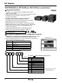
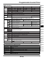
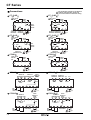
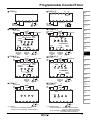
1
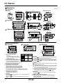
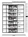
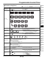
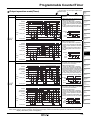
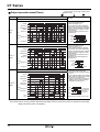
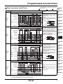
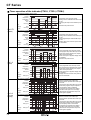
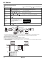
CT Series DIN W48×H48mm, W72×H36mm, W72×H72mm counter/timer Upgraded functions Upgrade ● Available to set 6 digits(0.00001 to 999999) prescale value (4digit : 0.001 to 9999) ● Built-in Modbus communication function(Communication model) ● Available to set the One-Shot output time in 10ms. (0.01sec. to 99.99sec.) ● Increase contact capacity to 5A(CTS, CTM Series) ● Available to set Count Start Point.(Initial value) ● Improved to select memory protection function in the indicator ● Added BATCH counter function(CTM Series) ● Added Counter Up-1 / Up-2 / Down-1 / Down-2 input modes ● Added Counter TOTAL / HOLD operation modes in the indicator ● Added Timer TOTAL / HOLD / On Time Display operation modes in the indicator ● Added Timer INT2 / NFD / NFD.1 / INTG output modes ● Added Timer range 999.999s / 9999m59 / 99999.9h Please read “Caution for your safety” in operation manual before using. DAQMaster(integrated device management program) ● DAQMaster is a integrated device management program for convenient management of parameters and multiple device data monitoring. ● Visit our website (www.autonics.com) to download user manual and integrated device management program. < DAQMaster screen > Item Minimum requirements IBM PC compatible computer with Intel Pentium Ⅲ or above Operating system Microsoft Windows 98/NT/XP/Vista/7 Memory 256MB or more Hard disk More than 1GB of free hard disk space VGA 1024×768 or higher resolution display Others RS-232 serial port(9-pin), USB port System Ordering information CT 6 M - 2P 4 T ※A shaded ( ) part is upgraded or added function. Communication No mark None 출력 회로의 수 T RS 485 Power supply Output Size Digit Item J-8 4 2 100-240VAC 50/60㎐ 24VAC 50/60㎐ / 24-48VDC 2P 1P I Dual preset Single preset Indicator S DIN W48×H48mm Y M DIN W72×H36mm DIN W72×H72mm 4 6 9999(4digit) 999999(6digit) CT Counter/Timer ※4digit type does not exist in the indicator type. Programmable Counter/Timer Specifications CTS CTY 4 6 6 CT6S-2P CT6Y-2P Dual Preset CT4S-2P CT6S-1P CT6Y-1P Single Preset CT4S-1P Model Single Preset CT6S-1 CT6Y-1 Single Preset 11mm 10mm 10mm Digit Size Single Preset 8mm 7mm 7mm Single Preset 100-240VAC 50/60Hz Power Supply Single Preset 24VAC 50/60Hz / 24-48VDC Allowable voltage range 90 to 110% of rated voltage(AC Power type) Single Preset Max. 12VA Power consumption Single Preset AC: Max. 10VA / DC: Max. 8W INA/INB Max. counting speed Selectable 1cps / 30cps / 1kcps / 5kcps / 10kcps Counter Reset signal : Selectable 1ms, 20ms Min. input signal width Timer INA, INB RESET : Selectable 1ms, 20ms Series Digit (A) Photo electric sensor CTM 6 CT6M-2P CT6M-1P CT6M-1 13mm 9mm (B) Fiber optic sensor (C) Door/Area sensor (D) Proximity sensor (E) Pressure sensor INA, INH, RESET, INHIBIT, BATCH RESET : Selectable 1ms, 20ms Selectable voltage input or No-voltage input Input [Voltage input] Input impedance is 5.4kΩ, 'H' level : 5-30VDC, 'L' level : 0-2VDC [No-voltage input] Short-circuit impedance : Max. 1kΩ, Residual voltage : Max. 2VDC One-shot output Count, timer : Selectable 0.01s to 99.99s Contact Dual preset : SPST(1a) 2EA Dual preset : SPST(1a) 1EA, SPDT(1c) 1EA With- output Single preset : SPDT(1c) 1EA Single preset : SPDT(1c) 1EA out Dual preset:3NPN open collector com. Solid state Dual preset : 1NPN open collector output Single preset : 1NPN open collector Single preset:2NPN open collector Contact Dual preset : SPST(1a)2EA Dual preset: SPST(1a), SPDT(1c) With- output Single preset : SPDT(1c)1EA Single preset: SPDT(1c) Control out output Dual preset: Dual preset:2NPN open collector com. Solid state output Single preset:1NPN open collector Single preset:2NPN open collector Contact 250VAC 5A resistive load 250VAC 3A resistive load 250VAC 5A resistive load With- output out com. Solid state 30VDC Max. 100mA Max. output External sensor power 12VDC ±10%, 100mA Max. Memory retention 10years(When using non-volatile semiconductor memory type) Repeat error SET error Power ON Start : Max. ±0.01% ±0.05 sec Timer Signal Start : Max. ±0.01% ±0.03 sec Voltage error Temperature error Insulation resistance Min. 100MΩ(500VDC Megger) Dielectric strength 2,000VAC 50/60Hz for 1minute Noise strength (AC Power) ±2kV the square wave noise(pulse width:1㎲) by the noise simulator Mechanical 0.75mm amplitude at frequency of 10 to 55(for 1 min.)Hz in each of X, Y, Z directions for 1 hour Vibration Malfunction 0.5mm amplitude at frequency of 10 to 55Hz(for 1 min.) in each of X, Y, Z directions for 10 minutes Mechanical 300m/s²(approx. 30G) in each of X, Y, Z directions for 3 times Shock Malfunction 100m/s²(approx. 10G) in each of X, Y, Z directions for 3 times Mechanical Min. 10,000,000 operations Relay Life cycle Electrical Min. 100,000 operations Protection IP65(Front panel only) Ambient -10 to 55℃, storage : -25 to 65℃ temperature Environment Ambient 35 to 85%RH, storage : 35 to 85%RH humidity Approval Unit weight Approx. 159g Approx. 149g Approx. 253g ※Environment resistance is rated at no freezing or condensation. Communication specification Protocol Connection method Application standard Number of connections Communication method Synchronous method Communication distance Communication speed Response waiting time Start bit Data bit Parity bit Stop bit (F) Rotary encoder (G) Connector/ Socket (H) Temp. controller (I) SSR/ Power controller (J) Counter (K) Timer (L) Panel meter (M) Tacho/ Speed/ Pulse meter (N) Display unit (O) Sensor controller (P) Switching mode power supply (Q) Stepper motor& Driver&Controller (R) Graphic/ Logic panel (S) Field network device Modbus RTU(16bit CRC) RS485 Compliance with EIA RS485 31, it is available to set address 1 to 127 Half Duplex Asynchronous within max. 800meter 2,400/4,800/9,600/19,200/38,400bps(Factory default : 9,600bps) 5 to 99ms(Factory default : 20ms) 1bit(Fixed) 8bits(Fixed) None, Even, Odd(Factory default : None) 1, 2bit(Factory default : 2bit) (T) Software (U) Other J-9 CT Series Connections Be careful that connections are different between communication model and non-communication model when wiring. CT S-2P CT S-2P T 12VDC 100mA INB / INH INA 12VDC 100mA INB / INH INA RESET 0VDC OUT2 30VDC 100mA OUT2 250VAC 5A RESISTIVE OUT1 250VAC 5A RESISTIVE - A(+) RESET 0VDC RS485 B(-) OUT2 OUT1 250VAC 5A 250VAC 5A RESISTIVE RESISTIVE + ※1 CT S-1P - + ※1 CT S-1P T 12VDC 100mA INB / INH INA 12VDC 100mA INB / INH INA RESET 0VDC OUT 30VDC 100mA OUT NO COM NC - + 250VAC 5A RESISTIVE LOAD RESET 0VDC A(+) OUT RS485 NO COM NC B(-) - 250VAC 5A RESISTIVE LOAD ※1 CT6S-I + ※1 CT6S-I T 12VDC 100mA INB / INH INA 12VDC 100mA INB / INH INA RESET 0VDC RS485 A(+) - RESET 0VDC B(-) - + + ※1 CT6Y-2P ※1 SOLID 250VAC 3A 250VAC 3A STATE OUT RESISTIVE LOAD RESISTIVE LOAD 30VDC 100mA NC COM OUT NO OUT1 OUT2 0VDC RESET INA INB / INH 12VDC 100mA OUT2 - ※1 CT6Y-1P 250VAC 3A RESISTIVE LOAD NC COM NO SOLID STATE OUT 30VDC 100mA J-10 250VAC 3A RESISTIVE 250VAC 3A RESISTIVE OUT2 OUT1 0VDC RESET - ※1 B(-) RS485 - + ※1 CT6Y-1P T SOLID 250VAC 3A STATE OUT RESISTIVE LOAD 30VDC NC COM NO 100mA A(+) OUT + A(+) 0VDC RESET INA INB / INH 12VDC 100mA OUT OUT INA INB / INH 12VDC 100mA + CT6Y-2P T INA INB / INH 12VDC 100mA OUT 0VDC RESET B(-) RS485 - + ※1 Programmable Counter/Timer CT6Y-I CT6Y-I T (A) Photo electric sensor B(-) A(+) RS485 - 0VDC RESET INA INB / INH 12VDC 100mA + ※1 CT6M-2P BATCH RESET SOLID STATE OUT 30VDC 100mA CT6M-1P ※2 INHIBIT RESET 0VDC 12VDC 100mA INB INA + B(-) ※1 OUT COM NC NO 250VAC 5A RESISTIVE LOAD 12VDC 100mA INB INA - (I) SSR/ Power controller + (J) Counter ※1 BATCH RESET (K) Timer ※2 INHIBIT RESET 0VDC BATCH RESET (L) Panel meter (M) Tacho/ Speed/ Pulse meter RS485 BATCH B(-) OUT BATCH (N) Display unit SOLID STATE OUT 30VDC OUT 100mA OUT CT6M-I (H) Temp. controller CT6M-1P T 12VDC 100mA INB INA A(+) NO COM NO 250VAC 5A RESISTIVE LOAD OUT2 BATCH SOLID STATE OUT 30VDC OUT2 100mA NO COM 250VAC 5A RESISTIVE LOAD SOLID STATE OUT 30VDC 100mA OUTPUT COMMON (F) Rotary encoder (G) Connector/ Socket OUT1 - BATCH RESET RS485 OUT2 COM NC NO 250VAC 5A RESISTIVE LOAD (D) Proximity sensor (E) Pressure sensor ※2 INHIBIT RESET 0VDC 12VDC 100mA INB INA A(+) NO COM 250VAC 5A RESISTIVE LOAD + ※1 OUTPUT COMMON OUT1 OUT2 BATCH OUT1 - (C) Door/Area sensor CT6M-2P T ※2 INHIBIT RESET 0VDC 12VDC 100mA INB INA 0VDC RESET INA INB / INH 12VDC 100mA (B) Fiber optic sensor - NO COM NO 250VAC 5A RESISTIVE LOAD + ※1 CT6M-I T ※2 INHIBIT RESET 0VDC - (O) Sensor controller (P) Switching mode power supply + ※1 (Q) Stepper motor& Driver&Controller ※2 INHIBIT RESET 0VDC 12VDC 100mA INB INA (R) Graphic/ Logic panel (S) Field network device RS485 A(+) (T) Software B(-) (U) Other - + ※1 ※1: Source - AC Power: 100-240VAC 50/60Hz - AC/DC Power: 24-48VDC, 24VAC 50/60Hz - + ※1 ※2: INHIBIT Signal - Counter operation: If INHIBIT signal is applied, count input will be prohibited. - Timer operation: If INHIBIT signal is applied, time progressing will stop.(HOLD) J-11 CT Series Dimensions (unit:mm) CTS Series ● Bracket 10 48 ● Panel cut-out 90 2 5 4 8 7 4 5 10 3 9 6 2 10 J-12 31.5 +0.6 0 68 +0.7 0 CTM Series 1 6 13 3 7 8 2 5 4 12 11 9 10 9. Mode key - By pressing MD key for 3sec (parameter setting)/ 5sec (communication) in RUN mode, it moves to function setting mode. - By pressing MD key in function setting mode, select function setting mode. By pressing MD key over 3 sec., it moves to Run mode. - By pressing MD key over 1 sec. in function setting checking mode, it moves to Run mode. 10. Set key ≪ : To enter into setting value(PS1, PS2) change status and shift digit of setting value(PS1, PS2). : To decrease setting value in setting value change mode, change setting value in function setting mode, move down checked value in function setting check mode. : To increase setting value in setting value change mode, change setting value in function setting mode, move up checked value in function setting check mode. By pressing MD key over 1 sec. in Run mode, enters into function setting check mode. 11. BATCH key By pressing BA key in run mode to enter into BATCH counter indication mode. 12. BATCH output indicator(red LED) 13. BATCH setting value checking and changing indicator (yellow-green LED) Lights when checking and changing BATCH setting value. ≫ Model Changed Notice 1. Count indicator(Red LED) CT6Y-1P - Run mode CT6S-1P PS2→PS There are no PS1, OUT1 : Count mode-Indicates count value. CT4S-1P OUT2→OUT LEDs. Timer mode-Indicates time progressing. CT6M-1P CT6Y-I - Function setting mode There are no CT6S-I PS2→PS PS1, OUT1 : Indicates function setting mode. OUT2 LEDs. CT6M-I 2. Preset value indicator (Yellow-Green LED) ※The indicator type does not exist - Run mode: Indicates preset value. in CT4S model. - Function setting mode: Indicates setting value1. 3. Key Lock : Lights when setting key lock. 4. The operation of counter indicator 5. The operation of timer indicator TMR LED flashes when the timer is operating. TMR LED lights when the operating time stops. 6. Check preset value and display change of it PS1 LED lights when checking or changing the setting value1. PS2 LED lights when checking or changing the setting value2. 7. Output(OUT1, OUT2) indicator OUT1 lights when output1 is on. OUT2 lights when output2 is on. 8. Reset key By pressing RST key in Run mode, the count value is initialized and output is returned. By pressing RST key in BATCH counter mode,BATCH count value resets. ≫ 6 3 7 8 9 1 68 +0.7 0 Min. 91 67 1 CTY Series 68 +0.7 0 ● Panel cut-out 85 10 72 Min. 40 30 36 86 Parts description 45.5 +0.5 0 Min. 91 77 6 72 CTS Series 45.5 +0.5 0 ● Panel cut-out 85 CTM Series Min. 62 Min. 91 CTY Series 45 60 Min. 55 Programmable Counter/Timer Input connections (A) Photo electric sensor No-voltage input(NPN) ● Solid-state input(Standard sensor : NPN output type sensor) Sensor Brown Black ※1 Counter/Timer CT Series Sensor +12V 5.4Ω +12V (NPN output) (C) Door/Area sensor +12V Inner circuit of input part Blue 0V Counter/Timer CT Series 5.4Ω Black ※1 Inner circuit of input part Blue Counter/Timer CT Series Brown (B) Fiber optic sensor ● Contact input ※2 5.4Ω (D) Proximity sensor Inner circuit of input part 0V (E) Pressure sensor 0V (NPN open collector output) (F) Rotary encoder ※1: INA, INB/INH, RESET, INHIBIT, BATCH RESET input part ※2: Counting speed: 1 or 30cps setting(Counter) (G) Connector/ Socket Voltage input(PNP) ● Solid-state input(Standard sensor : PNP output type sensor) Sensor Brown Counter/Timer CT Series +12V Black ※1 Blue Sensor Counter/Timer CT Series Brown 5.4㏀ (PNP output) Counter/Timer CT Series (I) SSR/ Power controller +12V Inner circuit of input part (J) Counter Inner circuit of input part 5.4㏀ Blue 0V ※2 +12V Black※1 Inner circuit of input part (H) Temp. controller ● Contact input 5.4Ω 0V (K) Timer 0V (PNP open collector output) (L) Panel meter ※1: INA, INB/INH, RESET, INHIBIT, BATCH RESET input part ※2: Counting speed: 1 or 30cps setting(Counter) (M) Tacho/ Speed/ Pulse meter (N) Display unit Input logic Selection[No-voltage input(NPN)/Voltage input(PNP)] 1. The power must be cut off. 2. Detach the case from the body. (CTS, CTY Series) ① ② 3. Select input logic by using input logic switch(SW1) inside Counter/Timer. (O) Sensor controller ● Select No-voltage input(NPN) (P) Switching mode power supply NPN PNP (Factory default) ● Select voltage input(PNP) NPN (Q) Stepper motor& Driver&Controller PNP (R) Graphic/ Logic panel (S) Field network device ① * Case detachment Squeeze toward ① and pull toward ② as shown in picture. Please check if the power is cut off. (T) Software <CTS Series> <CTY Series> <CTM Series> (U) Other 4. Push a case in the opposite direction of 2-②. 5. Then apply the power to Counter/Timer. J-13 CT Series Output connections Contact output Solid-state output Counter/Timer CT Series Counter/Timer CT Series ※1 Load (Power of load) (-) Load Communication Timer Counter Factory default Factory default UP/Down-C (UD-C) F (F) 30cps (30) TOTAL (TOTAL) Hold (HOLD) 100ms (0)10) ------ 20ms (20) NPN (NPN) 6digit type : -.-----, 4digit type : -.--- 6digit type : 1.00000,4digit type : 1.000 000000 Clear (SLR) Lock off (lOFF) 1000 (1000) 5000 (5000) 6Digit type: 0.001s-999.999s, 4Digit type: 0.001s-9.999s UP (UP) TOTAL (TOTAL) CLEAR (SLR) OND (OND) Hold (HOLD) 100ms (0)10) NPN (NPN) 20ms (20) Lock off (lOFF) 1000 (1000) 5000 (5000) 01 (001) 9600bps (96) NONE (NONE) 2 (2) 20ms (20) Enable (ENA) Error display Error display EEP PS1○ PS2○ J-14 FAIL Power for load (DC) ※Use proper load and power for load not to excess ON/OFF capacity(30VDC Max. 100mA max.) of solid state output. ※Be sure not to apply reverse polarity of power. ※1: When use inductive load(Relay etc), surge absorber (Diode, varistor etc) must be connected between both sides of the load. ※Use proper load not to exceed the capacity. Parameter Input mode (ㅑIN) Output mode (OUtM) CPS (CPS) Indication mode (indicator type)(DSpM) OUT2 output time (OUt2) OUT1 output time (OUt1) Decimal point (DP) Min. reset time (RST) Input logic (SIG) Prescale decimal point (ScDP) Prescale value (SCL) Start Point setting (STRT) Counting memory (DATA) Lock key (LOCK) Preset value 1 (PS1) Preset value 2 (PS2) Time range (HOUR/MIN/SEC) Up/Down mode (U-D) Indication mode(Indicator type)(DSpM) Memory protection(Indicator type) (DATA) Output mode (OUtM) OUT2 output time (OUT2) OUT1 output time (OUT1) Input logic (SIG) Input signal time (ImT) Lock key (LOCK) Preset value 1 (PS1) Preset value 2 (PS2) Communication address (ADDR) Communication speed (BPS) Communication parity (PRTY) Communication stop bit (STP) Response waiting time (RSWT) Communication writing (COmY) (+) Errors Output status How to return Failed in data loading for exsiting setting values OFF Power on again Programmable Counter/Timer Operations and functions RESET BATCH RESET ※1 Change of BATCH setting value. (A) Photo electric sensor ※1 Change of preset RUN mode BATCH counter indication mode ※BATCH counter is available for CT6M-1P/2P only. 3sec. 5sec. ※1. If no key is touched for 60 sec., the counter will return to RUN mode without being restored. 1sec. 1sec. (B) Fiber optic sensor Function setting check mode (C) Door/Area sensor (D) Proximity sensor 3sec. 3sec.: Enters into parameter 1 group 5sec.: Enters into parameter 2 group Function setting mode (F) Rotary encoder Change of preset(Counter/Timer) ●Even if changing the preset value, input operation and output control will continue. In addition, the preset value could be set to 0 and 0 preset value turns ON. According to output mode, preset value could not be set to 0. (When setting to 0, preset value "0" will flash 3 times.) 1. 2. (E) Pressure sensor (G) Connector/ Socket 3. (H) Temp. controller (I) SSR/ Power controller (J) Counter In Run mode, it enters into the preset value setting mode using key. 'PS1' LED lights and first digit of preset value flashes. The preset value is set to ' ' using , and keys, then press key to enter into the PS2 setting mode. (K) Timer The preset value is set to '200' using , and keys, then press key to complete PS2 setting and return to Run mode. (L) Panel meter ※Press key to save set value after changing the setting value. Then, it moves to next parameter or returns to RUN mode. However, if no key is touched for 60 sec., it will return to RUN mode without being saved. Function setting check mode ● Setting value of function setting mode can be confirmed using the and (M) Tacho/ Speed/ Pulse meter (N) Display unit keys. Switching display function in preset indicator ●Setting value 1(PS1) and setting value 2(PS2) are displayed each time pressing (In timer, it is available for output mode.) (O) Sensor controller key in dual preset model. (P) Switching mode power supply Reset ● In Run mode or function setting mode, if key or applying the signal to the RESET terminal on the back side, present value will be initialized and output will maintain off status. When selecting voltage input(PNP), short no. 10 and no. 12 terminals, or when selecting no-voltage input(NPN), short no. 11 and no. 12 terminals to reset. BATCH Counter(For CT6M-1P /CT6M-2P (Q) Stepper motor& Driver&Controller (R) Graphic/ Logic panel model only) In BATCH counter indication mode, 'BATCH counter value' is displayed in count indicator and 'BATCH counter setting value' is displayed in preset indicator. (S) Field network device Change of BATCH setting value If pressing key in Run mode, it will enter into BATCH counter indication mode. 1. (T) Software 2. It enters into settingvalue change mode using key. (BA.S lights, first digit of setting value flashes.) (U) Other BATCH value is set to '200' using , and keys, then press key to complete BATCH setting value and move to BATCH counter indication mode. J-15 CT Series BATCH counter operation Power ON OFF Preset output Batch Reset 999999 Batch setting value 0 BA.O LED ON OFF Batch ON output OFF BATCH counting operation ● BATCH counting value is increasing until BATCH reset signal applied. BATCH counting value will be circulated when it is over 999999. 1) BATCH counting operation in Counter : Counts the number of reaching setting value of CT6M-1P or reaching dual setting value of CT6M-2P 2) BATCH counting operation in Timer: Counts the number of reaching setting time. (In case of "FLK" output mode, count the number of reaching T.off setting time and T.on setting time.) BATCH output ● If input signal is applied while changing BATCH setting value, counting operation and output control will be performed. ● If BATCH count value equals to BATCH setting value, BATCH output will be ON and maintain ON status until BATCH reset signal is applied. ● When the power is cut off then resupplied in status of BATCH output is ON, BATCH output maintains ON status until BATCH reset signal is applied. BATCH reset input ● If pressing reset button or applying the signal to BATCH reset terminal on the back side panel, BATCH counting value will be reset. When selecting voltage input(PNP), short no. 10 and no. 14 terminals, or when selecting no-voltage input(NPN), short no. 11 and no. 14 terminals to reset. ● When BATCH reset is applied, BATCH counting value maintains at 0 and BATCH output maintains in the OFF status. Application of BATCH counter function ● Counter In case, put 5 products in a box then pack the boxes when they reaches to 200. - Counter preset setting value="5", BATCH setting value="200" - When the count value of counter reaches to the preset value "5", the control output(OUT) will be on, and at this time the count value of the BATCH counter will be increased by "1". The control box which is received the control output (OUT) repeatedly controls conveyor to move the full box and to place the next empty box for standby. When the BATCH count value reaches to "200", BATCH output will be ON. Then the control box stops conveyor and provides a control signal for packing. Count input BATCH output Control output (OUT) CT6M-1P4 Control box Preset value = 5 BATCH output lamp Control signal for packing Control signal for conveyor Third Second First box box box Current BATCH count value = 3 J-16 ● Timer Fills milk into the bottle for 3sec.(setting time) When 500 bottles are filled, BATCH counting finish lamp is turned on. (Setting time : 3sec., BATCH setting value : 500) Operation valve (Open valve for 3sec.) BATCH output Control output CT6M1P4 Control the operation valve Bottle sensing sensor Productivity : 500bottels Lamp on when it is completed. BATCH counting finish lamp Control box Programmable Counter/Timer Flow chart for function setting mode (A) Photo electric sensor Run mode 3sec. 3sec. 5sec. Parameter group1 , ※3 Counter/Timer (COUN) (GRp2) (C-T) Input mode Time range (IN) ※3 Output mode (ㅐㅕㅆOUtM) Indication mode ※1 (DSpM) ※3 Max. counting speed (CPS) ※2 ※3 Function setting mode OUT2 output time (OUT2) ※3 OUT1 output time (OUT1) ※3 Decimal point (DP) ※3 (HOUR/MIN/SEC) ※2 (RST) Up/Down mode (U-D) ※1 ※3 Indication mode (DSpM) Memorize counting value (DATA) ※3 Output mode (OUtM) ※3 OUT2 output time (OUT2) ※3 (OUT1) Input logic (SIG) (SIG) ※3 Prescale decimal point (ScDP) ※3 Prescale value (RST) ※3 Start Point value (STRT) Memorize counting value (LOCK) Communication (E) Pressure sensor Com. address (ADDR) ※3 Input logic Lock key (D) Proximity sensor (F) Rotary encoder Com. speed (BPS) (G) Connector/ Socket Com. parity (PRTY) (H) Temp. controller Com. stop bit (I) SSR/ Power controller (STP) Response waiting time (J) Counter (RSwT) (K) Timer Com. writing (COmW) (L) Panel meter OUT1 output time Min. reset time (DATA) (C) Door/Area sensor Timer (T1ME) ※3 3sec. Parameter group2 (GRp1) Counter (B) Fiber optic sensor Input signal time (InT) ※1: Indicator ※2: Output type ※3: If changing the setting value of function, OUT1, OUT2 will turn OFF and return to Run mode, then present value resets. (M) Tacho/ Speed/ Pulse meter (N) Display unit (O) Sensor controller Lock key (LOCK) (P) Switching mode power supply ※Counter - Single preset model has no "OUT1 output setting time" setting function mode and OUtT is displayed in "OUT2 output time" setting function mode. - In case of DN, DN-1, DN-2 input mode, there is no "Start Point value" setting function mode. - In case of F or N output mode, there is no "OUT2 output time" setting function mode.(Fixed to HOLD) - In case of S, T or D output mode, there is no "OUT2 output time" setting function mode. ※Timer - In case of FLk1, FLk2 or INtG output mode and OND, OND1, OND2 output mode of single preset model, OUtT is displayed in "OUT2 output time" function setting mode and there is no "OUT1 output time" function setting mode. (Q) Stepper motor& Driver&Controller (R) Graphic/ Logic panel (S) Field network device (T) Software - The output modes except for OND, ONd1, ONd2 and INt2 output mode there is no "OUT1 output time" function setting mode. ※If changing setting value of parameter group1, display value and output will be initialize. ※Press key over 3sec./5sec. in RUN mode to enter into parameter 1 group/ parameter 2 group. Press key over 3 sec. in function setting mode to return RUN mode. ※Input operation and output control can be set in function setting mode. ※If changing set value of ※3 marked parameters in function setting mode, OUT1 and OUT2 output will be turned OFF and then the current value is reset. ※Parameter 2 group is not available to non-communication models. J-17 (U) Other CT Series Parameter setting(Counter) ( Setting mode How to set Counter/Timer ㅊㅊC-T COUN Input mode IN UD-C key: To select setting mode, key: To change setting value) ※CONE: COUNTER TIME: TIMER TIME UP or UP-1 UP-2 DN DN-1 DN-2 UD-A UD-B ● UP, UP-1, UP-2 or DN, DN-1, DN-2 input mode N F C R K P Q A Output mode OUtM Indication mode DSpM Max. counting speed CPS ※In case that output mode is F, N there is no "OUT2 output time" setting mode. (Fixed to HOLD) ※If output mode is set to D when max. counting ● UD-A, UD-B, UD-C input mode N F C R K P Q A S T D speed is set to 5Kcps, 10Kcps, max. counting speed is automatically set to 30cps. (Factory default setting) ● In case of the indicator ※In case of the indicator, indicate mode selection (DSpM)is displayed. HOLD TOTAL ※It is added that the function which can set the preset value when selecting HOLD.(Refer to J-22 page 'Counter operation of the indicator'.) 30 1K SY 10K 1 ※Counting speed is that of one by one(1:1) duty ratio of INA or INB input signal, and it is applied in INA and INB at thesame time. ※In case of setting D in output mode, you can choose 1cps, 30cps, 1Kcps. OUT2 output time OUT2 : To shift flashing digit position of OUT2 output time value. : To change OUT2 output time value. OUT1 output time OUT1 : To shift flashing digit position of OUT1 output time value. : To change OUT1 output time value. ※1 Decimal point DP ● 6digit type ------ -----.- ● 4digit type ------.- --.-- Min. reset time RST 1 Input logic SIG NPN: No-Voltage input PNP: Voltage input ※1 Prescale decimal point ScDP 20 ----.--.--- ※Set OUT2 one-shot output time. ※Setting range: 0.01 to 99.99 sec. ※It does not appear if F, N output mode is selected. ※Set OUT1 one-shot setting time ※Time range: 0.01 to 99.99 sec., Hold ※HOLD is displayed by pressing key 4 times. ---.--- --.---- -.----- ※Setting the decimal point is applied same to counting value and setting value. ※Set the min. external RESET signal width. unit: ms ※Check input logic value(PNP, NPN). ● 6digit type ※Prescale decimal point position is not set below the decimal point setting digits (DP). ● 4digit type Prescale value SCL : To shift the flashing digit. : To change the prescale value. ※Setting range of prescale value 6digit type: 0.00001 to 99999.9 4digit type: 0.001 to 999.9 ※Refer to the J-20 page ' Prescale function'. Start Point Value STRT : To shift the flashing digit. : To change the Start Point value. ※Setting range of Start Point value (Connected with decimal point setting) 6digit type: 0.00000 to 999999 4digit type: 0.000 to 9999 ※Refer to the J-20 page ' Start Point function'. Memory protection DATA Lock key LOCK CLR REC LOFF LOc1 LOc3 LOc2 ※CLR: Initializes count value when power is off. ※REC : Memorizes count value at the moment of power off. ※LOFF:Cancellation of the lock mode. LOc1: Locks key. LOc2: Locks , , keys. LOc3: Locks , , , keys. ※1. Explanation of decimal point and prescale decimal point setting - Decimal point setting : Set decimal point of the display value on front indicator. - Prescale decimal point setting : Set prescale decimal point of counting regardless of decimal point of display value on front indicator. J-18 Programmable Counter/Timer Input operation mode(Counter) Input mode Count chart Operation INA H H INB L No counting (UP) Count 0 value 0 H INA L UP-1 Ⓐ Ⓐ INB H L Count value 0 0 Ⓐ n-1 n-2 INA H L DN-1 (Down-1) Count value INA DN-2 Ⓐ n n-1 (Up/Down-A) Count value n-5 n-6 (H) Temp. controller (I) SSR/ Power controller Ⓐ n n-4 0 1 2 3 4 n-4 2 1 (Q) Stepper motor& Driver&Controller 2 (R) Graphic/ Logic panel n-5 Ⓐ 3 (O) Sensor controller ※Counts when INA input signal is down. ( ) ※INA: Counting input ※INB: Inhibition input n-3 Ⓐ (N) Display unit (P) Switching mode power supply Ⓐ n-2 H L (M) Tacho/ Speed/ Pulse meter n-5 No counting n-1 (L) Panel meter ※Count when INA input signal is up. ( ) ※INA: Counting input ※INB: Inhibition input n-3 Ⓐ (K) Timer n-7 0 0 (G) Connector/ Socket ※If INA is counting input, INB is inhibition input. If INB is counting input, INA is inhibition input. No counting n-2 H INA L INB n-4 Ⓐ H L INB H L Count value n-3 0 (Down-2) UD-A Ⓐ 0 INB H L (F) Rotary encoder No counting Ⓐ n Count value (D) Proximity sensor (J) Counter INB H L (Down) (C) Door/Area sensor ※Counts when INA input signal is down. ( ) ※INA: Counting input ※INB: Inhibition input 4 3 2 1 INA H L DN Ⓐ No counting (Up-2) ※If INA is counting input, INB is inhibition input. If INB is counting input, INA is inhibition input. ※Counts when INA input signal is up. ( ) ※INA: Counting input ※INB: Inhibition input 5 4 3 INA H L UP-2 Ⓐ 2 1 0 0 7 (E) Pressure sensor No counting (Up-1) 6 5 4 3 2 1 H INB L Count value (B) Fiber optic sensor No counting L UP (A) Photo electric sensor 3 4 (S) Field network device ※INA: Counting input INB: Counting command input (T) Software ※When INB is L, counting Up. When INB is H, counting Down. (U) Other J-19 CT Series Input operation mode(Counter) Input mode Count chart Operation INA H L INB H L ㅕㅕUD-B (Up/Down-B) Count value 0 INA H L INB H L UD-C 2 1 0 0 4 3 2 2 3 4 BBBB (Up/Down-C) Count value 3 0 1 2 3 2 1 2 3 ※INA: Up counting input INB: Down counting input ※When both INA and INB are applied to L->H, it will remain previous counting value. ※When use A,B phase of encoder with connecting to INA, INB, please set counter input mode(IN) as phase different input(UD-C). ※ⓐ signal width should be over min. signal width and ⓑ signal width should be over a half min. signal width. If not, ±1 will occur. ※Min. signal width by counting speed ※The meaning of "H" and "L" Voltage input (NPN) No-Voltage input (PNP) H 5-30VDC Short circuit L 0-2VDC Open Counting speed 1cps 30cps 1kcps 5kcps 10kcps Min. signal width 500㎳ 16.7㎳ 0.5㎳ 0.1㎳ 0.05㎳ INA High (INB) Low ON OFF Ton Toff ON OFF T ※Ton, Toff : Min. signal width Prescale function(Counter) This function is to set and indicate calculated unit for actual length, liquid measure, position etc. It is called "Prescale value" for measured length, measured liquid, measured position, etc per 1 pulse. For example, P is the number of pulses per 1 revolution of a rotary encoder and L is the desired length to be measured. Prescale value is [the desired length (L)]/[the number of pulses (P) per 1 revolution of the rotary encoder.]. It is the length per 1 pulse of a rotary encoder. Ex) Control length by the counter and the rotary encoder Roller [In case of 22mm diameter(D) of roller connected with the encoder of 1,000 pulse] Cutter Rotary encoder ● Prescale value = Motor Motor controlling system = Counter π × Diameter of the roller(D) The number of pulses per 1 revolution of the encoder 3.1416 × 22 1000 = 0.069mm/pulse To control conveyor position in 0.1mm, set the decimal point to tenth place(-----.-) in decimal point setting mode(DP) and set the prescale decimal point to thousandth place(---.---) in prescale decimal point setting mode(ScDP)Then set prescale value "0.069" in prescale setting mode (SCL). Start point function(Counter) This function is that start point value works as initial value when on counting mode. ● In case of DN, DN-1 or DN-2 in timer input mode, it is not available. ● When reset is applied, the present value is initialized to start point. ● After count up in C, R, P, Q After count up in J-20 Programmable Counter/Timer Output operation mode(Counter) Output mode F (F) One-shot output(0.01 to 99.99 sec.) One-shot output Retained output Retained output Input mode Up, Up-1, 2 Down, Down-1, 2 Up/Down A, B, C RESET 999999 PRESET2 PRESET1 0 OUT1 OUT2 (OUT) N (N) C (C) RESET 999999 PRESET2 PRESET 1 0 OUT1 OUT2 (OUT) RESET 999999 PRESET2 PRESET 1 0 OUT1 OUT2 (OUT) R (R) K (K) P (P) RESET 999999 PRESET2 PRESET1 0 OUT1 OUT2 (OUT) RESET 999999 PRESET2 PRESET1 0 OUT1 OUT2 (OUT) RESET 999999 PRESET2 PRESET1 0 OUT1 OUT2 (OUT) Q (Q) RESET 999999 PRESET2 PRESET1 0 OUT1 OUT2 (OUT) A (A) RESET 999999 PRESET2 PRESET 1 0 OUT1 OUT2 (OUT) (A) Photo electric sensor (B) Fiber optic sensor Operation ※After count-up, counting display value increases or decreases until reset signal is applied and retained output is maintained. (C) Door/Area sensor (D) Proximity sensor (E) Pressure sensor ※After count- up, counting display value and retained output are maintained until reset signal is applied. (F) Rotary encoder (G) Connector/ Socket ※When count-up, counting display value will be reset and count simultaneously. ※OUT1 retained output will be off after OUT2 one- shot time. ※The one-shot output time of OUT1 one-shot output time is operated gardless of OUT2 output. ※After OUT2 one-shot time, counting display value will be reset and count simultaneously. ※OUT1 retained output will be off after OUT2 one-shot time. ※OUT1 one-shot output time is operated regardless of OUT2 output. ※After count-up, counting display value increases or decreases until RESET input is applied. ※OUT1 retained output is off after OUT2 one-shot time. ※OUT1 one-shot output time is operated regardless of OUT2 output. (H) Temp. controller (I) SSR/ Power controller (J) Counter (K) Timer (L) Panel meter (M) Tacho/ Speed/ Pulse meter (N) Display unit ※After count-up, counting display value is maintained while OUT2 output is on. Counting value is internally reset and counts simultaneously. ※When OUT2 output is off, displays counting value while OUT2 is ON, and it increases or decreases. ※OUT1 retained output is off after OUT2 one-shot time. ※OUT1 one-shot output time is operated regardless of OUT2 output. (O) Sensor controller ※After count-up, counting display value increases or decreases during OUT2 one-shot time. ※OUT1 retained output is off after OUT2 one-shot time. ※OUT1 one-shot output time is operated regardless of OUT2 output. (R) Graphic/ Logic panel ※After count-up, counting display value and OUT1 retained output are maintained until RESET input is applied. ※OUT1 one-shot output time is operated regardless of OUT2 output. ※The single preset type output(OUT) is operated as OUT2 of dual preset type. ※OUT1 output could be set to 0 in all modes and 0 value output turns ON. ※OUT2 output could not set to 0 in C(C). R(R), P(P) or Q(Q) output mode. J-21 (P) Switching mode power supply (Q) Stepper motor& Driver&Controller (S) Field network device (T) Software (U) Other CT Series Output operation mode(Counter) Output mode Up/Down - A, B, C Operation RESET 999999 PRESET2 PRESET1 0 -99999 OUT1 OUT2 (OUT) S (S) ※OUT1 and OUT2 keeps ON status in following condition: Counting display value ≧ PRESET1 Counting display value ≧ PRESET2 RESET 999999 PRESET2 PRESET1 0 -99999 OUT1 T (T) Retained output Coincidence output ※OUT1 output is off: Counting display value ≧ PRESET1 ※OUT2 keeps ON status in following condition: Counting display value ≧ PRESET2 OUT2 (OUT) RESET ※When counting display value is equal to setting value(PRESET1, PRESET2) only, OUT1 or OUT2 output keeps ON status. ※When setting 1kcps for counting speed, solid state contact output should be used. 999999 PRESET2 PRESET1 0 D (D) -99999 OUT1 OUT2 (OUT) ※The single preset type output(OUT) is operated as OUT2 of dual preset type. ※The dual preset model OUT1 output is operated as one-shot or retained output.(except S, T, D mode) ※OUT1 output could be set to 0 in all modes and 0 value output turns ON. ※OUT2 output could not set to 0 in C(C), R(R), P(P) or Q(Q) output mode. Counter operation of the indicator(CT6S-I, CT6Y-I, CT6M-I) Indicate mode (DSpM) TOTAL (TOTAL) HOLD Count chart In case of input mode is Up (Up, Up-1, Up-2) In case of input mode is Down (Down, Down-1, Down-2) RESET RESET 999999 999999 0 -99999 RESET 999999 PRESET 999999 PRESET 0 (HOLD) 0 Operation Count value increases or decreases until RESET input is applied. When reaching max. count value or min. count value, it will be reset and count simultaneously. Count value increases or decreases until RESET input is applied, count value indicator flashes when reaching preset value(Up count) or 0(Down count). 0 ● In case of the input mode is Command input (UD-A), Individual input(UD-B), Phase difference input(UD-C). RESET 999999 0 -99999 J-22 ※In case of UP/DOWN (UD-A, UD-B, UD-C) input mode, indication mode (DSpM) of the configuration is not displayed. Programmable Counter/Timer Parameter setting(Timer) Setting mode How to set Counter/Timer C-T COUN ( key: To select setting mode or key: To change setting value) (B) Fiber optic sensor ※COUN: COUNTER TIME: TIMER TIME (C) Door/Area sensor 6digit type SEC 99(999 SEC 999(99 0.001s to 999.999s 0.01s to 9999.99s HOUR 9999(9 0.1h to 99999.9h Timer range HOUR/MIN/SEC UP/DOWN mode U-D Indication mode DSpM Memory protection DATA Output mode OUtM SEC 9999(9 SEC 999999 M S 995(99 M S 9995(9 0.1s to 99999.9s 1s to 999999s 0.01s to 99m59.99s 0.1s to 999m59.9s H M 999959 H M 5 995959 MIN 999999 MIN 9999(9 M 5 999959 1m to 9999h59m 1s to 99h59m59s 1m to 999999m 0.1m to 99999.9m 1s to 9999m59s SEC 9(99 SEC 99(9 0.001s to 9.999s 0.01s to 99.99s 0.1s to 999.9s UP OND SEC 9959 1s to 9999s 1s to 99m59s HOUR 9999 H M 9959 MIN 9999 MIN 99(9 1h to 9999h 1m to 99h59m 1m to 9999s 0.1m to 999.9m (E) Pressure sensor (F) Rotary encoder (G) Connector/ Socket HOLD (I) SSR/ Power controller (J) Counter (K) Timer ONtD ONd2 FLK FLk1 INTG NFd1 NFD OFD FLk2 INt2 OUT1 output time OUT1 Input logic S1G ※NPN: No-Voltage input ※PNP: Voltage input Input signal time InT 1 LOc3 LOc2 (O) Sensor controller INt1 key: To shift flashing digit position of OUT1 output time value. key: To change OUT1 output time value. ※Set OUT1 one-shot output time. ※Setting range: 0.01 to 99.99sec., Hold ※HOLD is displayed by pressing key 4 times. [unit: ms] (N) Display unit INT OUT2 output time OUT2 LOc1 (M) Tacho/ Speed/ Pulse meter ※Used for the indicator only. ※치CLR : Initializes time value when power is off. REC : Memorizes time value at the moment of power off. ONd1 LOFF (L) Panel meter ※Used for the indicator only. ※ It is added that the feature which set the setting time when selecting H OLD or ONtD (Refer to J-28 page ' Timer operation for the indicator'). REC 20 (H) Temp. controller ※UP: Time proceeds from 0 to the setting value. ※DN: Time proceeds from the setting value to 0. DN TOTAL CLR SEC 9999 key: To shift flashing digit position of OUT2 output time value. key: To change OUT2 output time value. ※Set OUT2 one-shot output time. ※Setting range: 0.01 to 99.99sec. ※HOLD is displayed by pressing key 4 times. Lock key LOCK (D) Proximity sensor 4digit type SEC (999 (A) Photo electric sensor (P) Switching mode power supply (Q) Stepper motor& Driver&Controller (R) Graphic/ Logic panel (S) Field network device (T) Software ※Check input logic value(PNP, NPN). ※CTS/CTY: Set min. external INA, INH, RESET signal width. ※CTM: Set min. external INA, RESET, INHIBIT, BATCH RESET signal width. (U) Other ※LOFF: Cancellation of the lock mode LOc1: Locks key. LOc2: Locks , , keys. LOc3 : Locks , , , keys. J-23 CT Series One-shot output Retained output Output operation mode(Timer) Output mode Input mode Operation Signal On Delay(Power Reset) 1) Time starts when INA signal turns on. 2) When INA signal turns off, time resets. 3) When INA signal is on: Power ON Time Start is operated Power OFF Time Start is operated 4) Control output operates as retained or one-shot output. POWER INA(START) INH(INHIBIT) OND (OND) RESET Setting time2 UP Setting time1 Display Down One-shot output Retained output 0 INA Setting time2 T1 Setting time1 0 OUT1 T2 OUT2 (OUT) OUT1 T1: Setting time1 T2: Setting time2 OUT2 1) Time starts when INA signal turns on, if INA signal is applied repeatedly, only initial signal is recognized. 2) When INA signal is on: Power ON Time Start is operated Power OFF Time Start is operated 3) Control output operates as retained or one-shot output. 4) Only first INA input signal is valid in case INA input signal is repeatedly applied. Signal On Delay 1(Power Reset) POWER INA(START) INH(INHIBIT) RESET ONd1 (OND.1) Setting time2 UP Display Down Setting time1 0 Setting time2 INA T1 Setting time1 OUT1 0 T2 OUT2 (OUT) OUT1 T1: Setting time1 T2: Setting time2 OUT2 1) Time starts when power turns on. (There is no INA function.) 2) Time resets when reset turns on. Time starts when reset turns off. 3) Control output operates as retained or one-shot output. 4) It memorizes display value at the moment of power off. Power On Delay(Power Hold) POWER INA(START) INH(INHIBIT) RESET Setting time2 Setting time1 ONd2 UP (OND.2) Display Down HOLD 0 Setting time2 POWER Setting time1 0 T1 OUT1 T2 OUT2 (OUT) OUT1 OUT2 t 1) Time starts when INA signal turns on. 2) When INA signal is on: Power ON Time Start is operated Power OFF Time Start is operated 3) Control output operates as retained output, output turns off for the T.off time and turns off for the T.off time and turns on for the T.on time repeatedly. Ta+Tb = T.off setting time 4) The T.on time and T.off time must be set individually. 5) In case of using the contact output, min. setting time must be set over 100ms. Flicker(Power Reset) POWER INA(START) INH(INHIBIT) RESET T.off setting time T.on setting time FLK (FLK) UP Display Down 0 T.off setting time POWER T.on setting time 0 INA T.off OUT2(OUT) T1: Setting time1 T2: Setting time2 a t-a T.on Ta Tb T.on T.off T.on T.off T.on T.off T.off T.on T.off OUT2 (OUT) ※Power Reset: There is no memory protection.(Initializes the display value when power is off) Power Hold: There is memory protection.(Memorizes the display value at the moment of power off, indicates the memorized display value when power is resupplied.) J-24 Programmable Counter/Timer Output operation mode(Timer) One-shot output One-shot output Retained output Retained output Output mode Input mode Operation Flicker 1(Power Reset) 1) Time starts when INA signal turns on. 2) When INA signal is on: Power ON Time Start is operated Power OFF Time Start is operated 3) Control output operates as retained output. 4) In case of using the contact output, min. setting time must be set over 00ms. Hold output POWER INA(START) INH(INHIBIT) RESET Setting time Up Display Down FLk1 (FLK.1) INA T T OUT2 (OUT) 0 1) Time starts when INA signal turns on. 2) When INA signal is on: Power ON Time Start is operated Power OFF Time Start is operated 3) Control output operates as one-shot output. 4) In case of using the contact output, min. setting time must be set over 100ms. POWER INA(START) INH(INHIBIT) RESET Setting time Up Display Setting time INA 0 OUT2 (OUT) Down t t t T T POWER INA(START) INH(INHIBIT) RESET Setting time Up Display Down FLk2 (FLK.2) 0 INA 0 OUT2 (OUT) POWER INA(START) INH(INHIBIT) RESET Display Down Setting time 0 T T-c Hold c (L) Panel meter (M) Tacho/ Speed/ Pulse meter (N) Display unit (O) Sensor controller T (Q) Stepper motor& Driver&Controller T:Setting time (R) Graphic/ Logic panel (S) Field network device (T) Software POWER Setting time 0 t OUT2(OUT) (I) SSR/ Power controller (P) Switching mode power supply 1) Time starts when INA signal turns ON and the display value at the moment when power is off is memorized. 2) When INA signal is on: Power ON Time Start is operated Power OFF Time Start is operated 3) Control output operates as one-shot output. 4) In case of using the contact output, min. setting time must be set over 100ms. One-Shot output (H) Temp. controller (K) Timer POWER Setting time OUT2(OUT) Up T 1) Time starts when INA signal turns ON and the display value at the moment when power is off is memorized. 2) When INA signal is on: Power ON Time Start is operated Power OFF Time Start is operated 3) Control output operates as retained output. 4) Control output will be reversed when it reaches to setting time.(At the initial start, OUT2 control output is OFF). 5) In case of using the contact output, min. setting time must be set over 100ms. Hold output (G) Connector/ Socket T:Setting time OUT2(OUT) Flicker 2(Power Hold) (D) Proximity sensor (J) Counter POWER 0 (C) Door/Area sensor (F) Rotary encoder T T:Setting time OUT2(OUT) One-Shot output (B) Fiber optic sensor (E) Pressure sensor POWER 0 Setting time (A) Photo electric sensor t t a t-a t INA OUT2 (OUT) T T-c Hold c (U) Other T T:Setting time ※Power Reset: There is no memory protection.(Initializes the display value when power is off) Power Hold: There is memory protection.(Memorizes the display value at the moment of power off, indicates the memorized display value when power is resupplied.) J-25 CT Series Output operation mode(Timer) Output mode Input mode Interval (Power Reset) POWER INA(START) INH(INHIBIT) RESET ㅑㅜINT (INT) Setting time Up 0 Display Setting time Down 0 OUT2(OUT) Interval 1(Power Reset) POWER INA(START) INH(INHIBIT) INt1 (INT.1) RESET Setting time Up 0 Display Setting time Down 0 One-shot output One-shot output Retained output Retained output Operation 1) Control output turns ON and time starts when INA signal turns ON. 2) When INA signal is on: Power ON Time Start is operated Power OFF Time Start is operated 3) When it reaches setting time, indication value and control output are reset automatically. 4) Control output is ON when time is progressing. POWER INA POWER INA(START) INH(INHIBIT) RESET INt2 (INT.2) Setting time1 Up T T:Setting time 1) Control output turns ON and time starts when INA signal turns ON. 2) When INA signal is on: Power ON Time Start is operated Power OFF Time Start is operated 3) When it reaches setting time, indication value and control output are reset automatically. 4) Control output is ON when time is progressing. 5) INA input is ignored while time is progressing. POWER INA OUT2 (OUT) OUT2(OUT) Interval 2(Power Reset) T OUT2 (OUT) T T:Setting time 1) Time starts when INA input is ON and resets when INA input is OFF. 2) INA input is ON, OUT1 output is ON during T1 or t1. 3) When it reaches setting time1, display value resets and OUT2 output is ON during T2 or t2 output time. ※ Output turns OFF when reaching the setting time even if one-shot time is longer than setting time. Setting time2 0 Display Setting time2 Down Setting time1 0 OUT1 OUT2 INA T1 OUT1 OUT2 T2 t1 T1: Setting time1 T2: Setting time2 t1: One-shot1 t2: One-shot2 t2 (Single preset model has no INT.2 mode) ※Power Reset: There is no memory protection.(Initializes the display value when power is off) Power Hold: There is memory protection.(Memorizes the display value at the moment of power off, indicates the memorized display value when power is resupplied.) J-26 Programmable Counter/Timer Output operation mode(Timer) Output mode Input mode Signal Off Delay1(Power Reset) POWER INA(START) INH(INHIBIT) RESET OFD (OFD) Setting time Up Display Down 0 Setting time 0 OUT2(OUT) On-Off Delay (Power Reset) POWER INA(START) INH(INHIBIT) RESET NFD (NFD) On_Delay Off_Delay Up Display Down 0 On_Delay Off_Delay 0 One-shot output One-shot output Retained output Retained output Operation 1) If INA is ON, control output remains ON. (except when power is off and reset is on) 2) When INA signal is OFF, time processes. 3) When it reaches setting time, indication value and control output are reset automatically. POWER INA T OUT2 (OUT) T: Setting time T1 OUT2 (OUT) POWER INA(START) INH(INHIBIT) RESET NFd1 Up (NFD.1) Display Up Down Display Down On_Delay Off_Delay 0 On_Delay Off_Delay 0 OUT2(OUT) OUT2 (OUT) T1 T2 POWER INTG (INTG) Up Display Down 0 Setting time (G) Connector/ Socket (H) Temp. controller (I) SSR/ Power controller (L) Panel meter (M) Tacho/ Speed/ Pulse meter (N) Display unit (O) Sensor controller (P) Switching mode power supply (R) Graphic/ Logic panel INA(START) RESET Setting time (E) Pressure sensor (Q) Stepper motor& Driver&Controller T1: On_Delay T2: Off_Delay Integration Time(Power Reset) INH(INHIBIT) (D) Proximity sensor (K) Timer T1: On_Delay T2: Off_Delay 1) When INA input turns ON, time progresses and output turns ON after On_Delay time. 2) When INA input turns OFF, time progresses and output turns OFF after Off_Delay time. 3) If INA input turns OFF within On_ Delay time, output will turn ON and step2 operate. 4) If INA input turns ON within Off_ Delay time, output will turn OFF and step1 operate. INA (C) Door/Area sensor (J) Counter T2 OUT2(OUT) On-Off Delay1 (Power Hold) (B) Fiber optic sensor (F) Rotary encoder 1) When INA input is ON, output is ON and time is progressing, then output is OFF after On_Delay time. 2) When INA input is OFF, output is ON and time is progressing, then output is OFF after Off_Delay time. 3) If INA input is OFF within On_Delay time, step 2 starts again. 4) If INA input is ON within Off_Delay time, step 1 starts again. INA (A) Photo electric sensor 1) Time is progressing while INA input is ON. 2) Time progress stops while INA input is OFF. 3) When it reaches the setting time, output is ON. 0 OUT2(OUT) ※Power Reset: There is no memory protection.(Initializes the display value and the output status when re-supplying the power.) Power Hold: There is memory protection.(It memorizes the status of power off. When re-supplying the power, it returns the memorized display value and the output status.) J-27 (S) Field network device (T) Software (U) Other CT Series Timer operation of the indicator(CT6S-I, CT6Y-I, CT6M-I) When memory protection setting is OFF POWER INA(START) INH(INHIBIT) Up Display TOTAL (TOTAL) Down RESET Max. time range 0 Max. time range 1) Time starts when INA input is ON. 2) Setting value is initialized when Reset input is ON. 3) Time progress stops when INHIBIT input is ON. 4) Resets when power is OFF. 0 When memory protection setting is ON POWER INA(START) INH(INHIBIT) Up Display Down RESET Max. time range 0 Max. time range 1) Time starts when INA input is ON. 2) Setting value is initialized when Reset input is ON. 3) Time progress stops while INHIBIT input is ON. 4) Display value at the moment of power OFF is memorized. 0 When memory protection setting is OFF POWER INA(START) INH(INHIBIT) RESET Up Display HOLD (HOLD) Down Setting time 0 Setting time 0 When memory protection setting is ON POWER INA(START) INH(INHIBIT) RESET Up Display Setting time 0 Setting time Down 0 When memory protection setting is OFF POWER INA(START) INH(INHIBIT) RESET Up Display ONtD (On Time Display) Setting time 0 Setting time Down 0 When memory protection setting is ON POWER INA(START) INH(INHIBIT) RESET Setting time Up Display 0 Setting time Down 0 J-28 1) Time progresses when INA input is ON. 2) Time progress stops while INA input is OFF. 3) When time reaches setting time, display value will stop and flash. 4) When reset input is applied, display value is initialized. 5) Resets when power is OFF. 1) Time progresses when INA input is ON. 2) Time progress stops while INA input is OFF. 3) When time reaches setting time, display value will stop and flash. 4) When reset input is applied, display value is initialized. 5) Display value the moment when power is OFF is memorized. ※ON time indicate mode of INA input 1) Time reset start operates when INA input turns ON. 2) Time progress stops while INA input is OFF. 3) When time progress stops and power is off, the display value is initialized. 4) If progress time is greater than setting time when INA input turns off, display value flashes and operation stops until reset signal is applied. ※ON time indicate mode of INA input 1) Time reset start operates when INA input turns ON. 2) Time progress stops while INA input is OFF. 3) When time progress stops and power is off, the display value is memorized. 4) If progress time is greater than setting time when INA input turns off, display value flashes and operation stops until reset signal is applied. Programmable Counter/Timer Timer '0' time setting (A) Photo electric sensor Available output operation mode to set '0' time setting OND, ONd1, ONd2, NFD, NFd1 Operation according to output mode(at 0 time setting) 1) OND(Signal ON Delay) mode [OND] ● Setting time1 is set to 0 UP mode DOWN mode INA(START) (B) Fiber optic sensor ● Setting time2 is set to 0 INA(START) 0 0 (E) Pressure sensor OUT1 OUT1 OUT2 OUT2 2) OND.1(Signal ON Delay 1) mode [ONd1] ● Setting time1 is set to 0 UP mode DOWN mode INA(START) (F) Rotary encoder ● Setting time2 is set to 0 (G) Connector/ Socket INA(START) RESET Setting time1 RESET Setting time2 (H) Temp. controller 0 0 OUT1 OUT1 (I) SSR/ Power controller OUT2 OUT2 3) OND.2(Power ON Delay2) mode [ONd2] ● Setting time1 is set to 0 UP mode ● Setting time2 is set to 0 POWER RESET Setting time 1 RESET Setting time1 0 0 OUT1 OUT1 OUT2 OUT2 4) NFD(ON-OFF Delay) mode [NFD] ● OFF_Delay setting time is set to 0 Up OUT2 (OUT) (O) Sensor controller Off_Delay 0 (P) Switching mode power supply (Q) Stepper motor& Driver&Controller OUT2 (OUT) ● ON_Delay setting time is set to 0 (R) Graphic/ Logic panel INA(START) RESET RESET Display On_Delay 0 Down (N) Display unit Display Off_Delay 0 Down INA(START) On_Delay 0 (M) Tacho/ Speed/ Pulse meter RESET OUT2 (OUT) 5) NFD.1(ON-OFF Delay1) mode [NFd1] ● OFF_Delay setting time is set to 0 (L) Panel meter INA(START) RESET Display On_Delay 0 Down (K) Timer ● ON_Delay setting time is set to 0 INA(START) On_Delay 0 (J) Counter UP mode DOWN mode POWER Up (D) Proximity sensor Setting time 2 Setting time2 Up (C) Door/Area sensor Up (S) Field network device Off_Delay 0 Display Off_Delay 0 Down (T) Software OUT2 (OUT) (U) Other Setting value1(PS1) is higher than Setting value2(PS2) OND(OND), OND.1(ONd1)or OND.2(ONd2)output mode ● UP mode: When the timer setting value1 is greater than the setting value 2, OUT1 output does not turn ON. ● DOWN mode: When the timer setting value1 is greater than the setting value 2, OUT1 output does not turn ON. If the setting value 1 is same as the setting value2 and START signal is applied, OUT1 output turns ON immediately. J-29 CT Series Communication mode Parameter setting Setting mode ( key: To select setting mode, or key: To change setting value) How to set ※Setting range of com. address: 1 to 127 : To shift flashing digits of Com. address. ※If the same address is applied during multicom., : To change the flashing digits. it will not work correctly. Com. address (ADDR) Com. speed (BPS) 24 Com. parity (PRTY) NONE Com. stop bit (STP) 1 48 96 192 EVEN 384 ※2400/4800/9600/19200/38400bps ※NONE: None EVEN : Even number ODD: Odd number ODD 2 ※Setting range according to com. speed. : To shift flashing digits position of com. response waiting time. : To change the flashing digits position value. esponse waiting time (RSwT) Com. write (COmW) ENA 2400bps 4800bps 9600bps 19200bps 38400bps 16ms to 99ms 8ms to 99ms 5ms to 99ms 5ms to 99ms 5ms to 99ms ※ENA : Permits com. write(Enable) DISA : Prohibits com. write(Disable) DISA Application of system organization RS485 RS232C RxD - RxD TxD - TxD GND - GND GND V(12-24VDC) Terminating resistance B(-) B(1) A(+) RS232C Cable Computer A(+) B(-) B(-) ON A(+) OFF A(+) B(-) CT Series #31 A(+) B(-) CT Series CT Series #01 #02 CT Series #30 A(+) ※It is recommended to use communication converter, RS485 to Serial converter(SCM-38I, sold separately), USB to RS485 converter(SCM-US48I, sold separately). Please use a proper twist pair for RS485 communication. Communication control ordering A ※A → Min. 1sec. after applying power B → 38400bps: Approx. 1ms. 19200bps: Approx. 2ms. 9600bps: Approx. 4ms. 4800bps: Approx. 8ms. 2400bps: Approx. 16ms. C → Min. 20ms J-30 C Data Data CRC16 Command Address code B CRC16 CT Series Command Data CRC16 Command Address code Upper system Address code 1. The communication method is Modbus RTU(PI-MBUS-300-REV.J). 2. After 1sec. of power supply into the high order system, it starts to communicate. 3. Initial communication will be started by the high order system. When a command comes out from the high order system, CT Series will respond. Programmable Counter/Timer Communication command and block (A) Photo electric sensor The format of query and response 1) Read Coil Status(Func 01 H), Read Input Status(Func 02 H 5) Preset Multiple Registers(Func 10 H) ● Query(Master) ● Query(Master) Starting Slave Address Address Function High Low 1Byte 1Byte 1Byte 1Byte No. of Points High 1Byte Low 1Byte Error Check (CRC 16) Low High 1Byte 1Byte CRC 16 Data Data Data 1Byte 1Byte 1Byte 1Byte Error Check (CRC 16) Low High 1Byte 1Byte CRC 16 2) Read Holding Registers(Func 03 H), Read Input Registers(Func 04 H) ● Query(Master) Starting Slave Address Address Function High Low 1Byte 1Byte 1Byte 1Byte No. of Points High 1Byte Low 1Byte Error Check (CRC 16) Low High 1Byte 1Byte CRC 16 ● Response(Slave) Error Check Data Data Slave Function Byte Data (CRC 16) Address Count High Low High Low High Low Low High 1Byte 1Byte 1Byte 1Byte 1Byte 1Byte 1Byte 1Byte 1Byte 1Byte 1Byte CRC 16 3) Force Single Coil(Func 05 H) ● Query(Master) Coil Address Slave Address Function High Low 1Byte 1Byte 1Byte 1Byte Force Data High 1Byte Low 1Byte Error Check (CRC 16) Low High 1Byte 1Byte CRC 16 ● Response(Slave) Coil Address Slave Function Address High Low Force Data High Low Error Check (CRC 16) Low High 1Byte 1Byte 1Byte 1Byte 1Byte 1Byte 1Byte 1Byte CRC 16 Register Slave Address Address Function High Low Preset Data High Low Error Check (CRC 16) Low High 1Byte 1Byte 1Byte 1Byte 1Byte 1Byte Byte Count High Low High Low Data Error Check (CRC 16) Data High Low High Low Low High ● Response(Slave) Slave Function Address Starting Address No. of Register Error Check (CRC 16) High Low High Low Low High 1Byte 1Byte 1Byte 1Byte 1Byte 1Byte 1Byte 1Byte (G) Connector/ Socket CRC 16 (H) Temp. controller Read Coil Status(Func 01 H) Master reads OUT2 00002(0001H) to 00003(0002H), OUT1 output status(ON : 1, OFF : 0) from the Slave(Address 01). ● Query(Master) (I) SSR/ Power controller Starting Address Slave Function Address High Low No. of Points Error Check (CRC 16) High Low Low High 01 H 00 H 02 H EC H 0B H 00 H 01 H (J) Counter (K) Timer On slave side OUT2 00003(0002H) : OFF, OUT1 00002(0001H) : ON ● Response(Slave) Slave Address Function 01 H 01 H (L) Panel meter Error Check (CRC 16) Low High D0 H 49 H Data Byte Count (00003 to 00001) 01 H 02 H (M) Tacho/ Speed/ Pulse meter Read Input Register (Func 04 H)Master reads preset value 21004(03EBH) to 21005(03ECH) of counter/timer, Slave (Address 15). ● Query(Master) Starting Address Slave Function Address High Low No. of Points High Low Error Check (CRC 16) Low High 0F H 00 H 02 H 00 H 04 H 03 H EB H 95 H Error Check (CRC 16) Data Data High Low High Low Low High 0F H E2 H 40 H 00 H 01 H E2 H 28 H (T) Software 1Byte (U) Other Register Slave Address Address Function High Low Preset Data High Low Error Check (CRC 16) Low High 1Byte 1Byte 1Byte 1Byte 1Byte 1Byte (Q) Stepper motor& Driver&Controller (S) Field network device CRC 16 ● Response(Slave) 1Byte (O) Sensor controller (R) Graphic/ Logic panel Slave Byte Function Count Address 04 H (N) Display unit (P) Switching mode power supply In case that the present value is 123456(0001 E240 H) in slave side, 31004(03EBH): E240 H, 31005(03ECH): 0001H 04 H (D) Proximity sensor (F) Rotary encoder 6) Application 01 H (C) Door/Area sensor (E) Pressure sensor ● Response(Slave) 4) Preset Single Register(Func 06 H) ● Query(Master) 1Byte No. of Register CRC 16 Byte Slave Address Function Count 1Byte Starting Slave Address Function Address 1Byte 1Byte 1Byte 1Byte 1Byte 1Byte 1Byte 1Byte 1Byte 1Byte 1Byte 1Byte 1Byte ● Response(Slave) 1Byte (B) Fiber optic sensor 1Byte CRC 16 J-31 CT Series Modbus Mapping Table 1) Reset/Output No(Address) 00001(0000) 00002(0001) 00003(0002) Func 01/05 01 01 00004(0003) 01 4) Monitoring data Explanation Reset OUT2 output OUT1 output Setting range Notice 0:OFF 1:ON 0:OFF 1:ON 0:OFF 1:ON For BATCH BATCH output 0:OFF 1:ON output model For BATCH 00005(0004) 01/05 BATCH resets 0:OFF 1:ON output model 2) Terminal input status No(Address) Func Explanation 10001(0000) 02 10002(0001) 02 10003(0002) 02 10004(0003) 02 10005(0004) 02 Setting range Notice Terminal input INA input status 0:OFF 1:ON status Terminal input INB input status 0:OFF 1:ON status Terminal input INHIBIT input status 0:OFF 1:ON status Terminal input RESET input status 0:OFF 1:ON status BATCH RESET Terminal input 0:OFF 1:ON input status status 3) Product Information No(Address) 30001~30100 30101(0064) 30102(0065) 30103(0066) 30104(0067) 30105(0068) 30106(0069) 30107(006A) 30108(006B) 30109(006C) 30110(006D) 30111(006E) 30112(006F) 30113(0070) 30114(0071) 30115(0072) 30116(0073) 30117(0074) Func 04 04 04 04 04 04 04 04 04 04 04 04 04 04 04 04 04 04 30120(0077) 04 Explanation Reserved Product number H Product number L Hardware version Software version Model no. 1 Model no. 2 Model no. 3 Model no. 4 Reserved Reserved Reserved Reserved Reserved Reserved Reserved Reserved Reserved Coil Status Start Address Coil Status Quantity Input Status Start Address 30121(0078) 04 30122(0079) 04 30118(0075) 04 Notice Model ID "CT" "6M" "-2" "PT" 0000 No(Address) Func Explanation BA.O LED display status OUT2 LED display status OUT1 LED display status BA.S LED display status 31001 LOCK LED 04 display status (03E8) PS2 LED display status PS1 LED display status TMR LED display status CNT LED display status Present value 31002(03E9) 04 of BATCH 31003(03EA) counter 31004(03EB) 31005(03EC) 04 31006(03ED) 04 31007(03EE) 31008(03EF) 04 31009(03F0) 31010(03F1) 31011(03F2) 31012(03F3) 04 04 31013(03F4) 04 Setting range Notice 0:OFF 1:ON Bit 5 0:OFF 1:ON Bit 6 0:OFF 1:ON Bit 7 0:OFF 1:ON Bit 10 0:OFF 1:ON Bit 11 0:OFF 1:ON Bit 12 0:OFF 1:ON Bit 13 0:OFF 1:ON Bit 14 0:OFF 1:ON Bit 15 0 to 999999 For BATCH output model Counter -99999 to Present value 6digit type: 999999 Use counter of and timer 4digit type: -999 to 9999 counter/timer Timer: Within time setting in common range Counter: Counter: decimal point 40058 Data of display value Timer: Timer: Time range 40102 Data Counter 6digit type: -99999 to Use counter PS(2) 999999 timer setting value 4digit type: -999 to 9999 and Timer: Within time setting in common range Counter 6digit type: -99999 to Use counter PS1 999999 timer setting value 4digit type: -999 to 9999 and Timer: Within time setting in common range Setting value Use counter of BATCH 0 to 999999 and timer counter in common Checking the 0: NPN, 1 : PNP input logic Display unit - ● Date format of 31001(03E8) address bit 0000 Bit 15 Bit 14 Bit 13 Bit 12 Bit 11 Bit 10 Bit 9 Bit 8 Bit 7 Bit 6 Bit 5 Bit4 Bit 3 Bit 2 Bit 1 Bit 0 Input Status Quantity - CNT TMR PS1 PS2 LOCK BA.S - - OUT1 OUT2 BA.O - - - - - 0 or 1 0 or 1 0 or 1 0 or 1 0 or 1 0 or 1 0 0 0 or 1 0 or 1 0 or 1 0 0 0 0 0 0000 - 30124(007B) 04 Holding Register Start Address Holding Register Quantity Input Register Start Address 30125(007C) 04 Input Register Quantity - 30119(0076) 04 30123(007A) 04 J-32 0064 ※2 Words data format: Upper data has high number address. Ex)31004 : Present Value(Low Word), 31005 : Present Value(High Word) 5) Preset value setting group No(Address) Func 40001(0000) 03 06 40002(0001) 16 40003(0002) 03 06 40004(0002) 16 40005(0004) 03 06 40006(0005) 16 Explanation Setting range Counter PS2 setting value PS setting value 6digit type: 0 to 999999 4digit type: 0 to 9999 PS1 setting Timer: Within time value setting range BATCH counter 0 to 999999 setting value Notice Use counter and timer in common Use counter and timer in common Use counter and timer in common Programmable Counter/Timer 6) Function setting mode (Counter group) No(Address) 40051(0032) 40052(0033) Func 03/06/16 03/06/16 40053(0034) 03/06/16 40054(0035) 03/06/16 40055(0036) 03/06/16 40056(0037) 40057(0038) 03/06/16 03/06/16 40058(0039) 03/06/16 40059(003A) 03/06/16 40060(003B) 03/06/16 40061(003C) 40062(003D) 40063(003E) 40064(003F) 40065(0040) 40066(0041) 03/06/16 03/06/16 03/06/16 03/06/16 Explanation Counter/Timer(C-T) Setting range 1: COUN 1: TIME Input mode(IN) 0: UP 1: UP-1 2: UP-2 3: DN 4: DN-1 (A) Photo electric sensor Notice Use counter and timer in common 5: DN-2 6: UD-A 7: UD-B 8: UD-C (B) Fiber optic sensor - (C) Door/Area sensor Indication mode(DISM) 0: TOTAL 1: HOLD 0: F 3: R 6: Q 9: T Output mode(OUTM) 1: N 4: K 7: A 10: D 5: P 8: S 2: C Maximum counting 0: 1 2: 1K 4: 10K 1: 30 3: 5K speed(CPS) OUT2(OUT) output time 0001~ 9999 0001~ 9999 OUT1 Output time 0: ------ 2: ----.-- 4: --.---Decimal point(DP) 1: -----.- 3: ---.--- 5: -.----0: 1 Min. reset time(RST) 1: 20 Prescale decimal 0: -----.- 3: ---.--- 5: -.----2: ----.-- 4: --.---point position(SClD) 6digit type: )00001 to 999999 Prescale value(SCL) 4digit type: )001 to 9999 6digit type: 000000to 999999 Start value(STRT) 4digit type: 0000to 9999 Memory protection(DATA) 0: CLR 1: REC Lock key(LOCK) 0: lOFF 1: LOc1 2: LOc2 3: LOc3 For the indicator (D) Proximity sensor - (E) Pressure sensor unit: ×10㎳ unit: ×10㎳ 4digit type 0: ---1: ---.- 2: --.-- 3: -.--unit: ms 4digit type 1: ---.- 2: --.-- 3: -.--Connected with prescale decimal point position Connected with decimal point position of display value Use counter and timer in common (F) Rotary encoder (G) Connector/ Socket (H) Temp. controller (I) SSR/ Power controller (J) Counter 7) Function setting mode (Timer group) No(Address) Func Explanation 40101(0064) 03/06/16 Counter/Timer(C-T) Setting range Notice 0: COUN 1: TIME Use counter and timer in common (K) Timer 4digit type 40102(0065) 03/06/16 Time range (HOUR/MIN/SEC) 0: 0.001s to 9.999s 1: 0.01s to 99.99s 2: 0.1s to 999.9s 3: 1s to 9999s 4: 1s to 99m59s 0: 0.001s to 999.999s 1: 0.01s to 9999.99s 2: 0.1s to 99999.9s 3: 1s to 999999s 4: 0.01s to 99m59.99s 5: 0.1s to 999m59.9s 03/06/16 UP/Down mode (U-D) 0: UP 40104(0067) 03/06/16 Output mode (OUTM) 0: OND 1: ONd1 2: ONd2 40105(0068) 03/06/16 40106(0069) 03/06/16 40107(006A) 40108(006B) 40109(006C) 40110(006D) 03/06/16 03/06/16 03/06/16 03/06/16 OUT2(OUT) Output time (OUT2) OUT1 Output time (OUT1) Input signal time(INT) Memory protection(DATA) Lock key(LOCK) ndication mode(DSpM) (M) Tacho/ Speed/ Pulse meter - 6digit type 40103(0066) (L) Panel meter 5: 0.1m to 999.9m 6: 1m to 9999m 7: 1m to 99h59m 8: 1h to 9999h (O) Sensor controller 7: INt1 8: INt2 9: OFD 10: NFD 11: NFd1 12: INtG unit: ×10ms 0000 to 9999(0 : Hold) unit: ×10,ms 0: 0: 0: 0: unit: ms Use counter and timer in common Use counter and timer in common For the indicator 1: 20 1: REC 1: LOc1 1: HOLD 2: LOc2 2: ONtD 3: LOc3 (Q) Stepper motor& Driver&Controller - 0000 to 9999(0: Hold) 1 CLR lOFF TOTAL (P) Switching mode power supply - 1: DN 3: FLK 4: FLk1 5: FLk2 (N) Display unit 6: 1s to 9999m59s 7: 1m to 99999.9m 8: 1m to 999999m 9: 1s to 99h59m59s 10: 1m to 9999h59m 11: 0.1h to 99999.9h (R) Graphic/ Logic panel (S) Field network device (T) Software (U) Other J-33 CT Series 8) Function setting mode (Communication group) No(Address) Func Explanation Setting range Notice 40151(0096) 40152(0097) 40153(0098) 40154(0099) 40155(009A) 40156(009B) 03/06/16 03/06/16 03/06/16 03/06/16 03/06/16 03/06/16 Com. address (ADDR) Com. speed (BPS) Com. parity (PRTY) Stop bit (STP) Response waiting time (RSwT) Com. writing (COmW) 1 to 127 0: 24 1: 48 2: 96 3: 192 4: 384 0: NONE 1: EVEN 2: ODD 0: 1 1: 2 05 to 99 0: ENA 1: DISA unit: ×100bps unit: ms - Exception processing When communication error occurs, the highest bit of received function is set to 1, then sends response command and transmits exception code. Slave Address Function+80H Exception Code 1Byte 1Byte 1Byte Error Check(CRC16) Low 1Byte High 1Byte ● Illeegal Function(Exception Code: 01H): Not supporting command ● Illegal Data Address(Exception Code: 02H): Mismatch between the number of asked data and the number of transmittable data. ● Illegal Data Value(Exception Code: 03H): Mismatch between asked the number of data and transmittable the number of data in device ● Slave Device Failure(Exception Code: 04H): Command is processed incorrectly. Example) Master reads output status (ON:1, OFF:0) of non existing coil 01001 (03E8 H) from Slave (Address17). ● Query(Master) Slave Address Function 11H 01H Starting Address High 03H No. of Points Low E8H Error Check(CRC16) High 00H Low 01H Low ##H High ##H ● Response(Slave) Slave Address Function + 80H Exception Code 11H 81H 02H Error Check(CRC16) Low High ##H ##H Read and write of parameter value using communication Read of the parameter area 00002(OUT2), 00003(OUT1), 00004(BA, 0), 10001 to 10005(Terminal input), 30101 to 30125(Product information), 31001 to 31013(Monitoring data) Read and write of the parameter area 00001(Reset starts), 00005(BATCH Reset starts), 40001 to 40006(Setting value saving group), 40051 to 40066(Counter setting group), 40101 to 40110(Timer setting group), 40151 to 40156(Communication setting group) Read of communication Read parameter value using communication.(Function : 01H, 02H, 03H, 04H) It is able to read communication regardless of permitting/prohibiting communication writing. Communication write Change parameter value using communication.(Function: 05H, 06H, 10H) ● When change the parameter setting value of ' Function setting mode Counter group' or ' Function setting mode Timer group' using communication, reset indication will flash in 3 sec. and display value will be reset.(Counting display value and progress time before changing parameter setting value are not saved.) ● When change the parameter setting value of ' Preset value setting group' or ' Function setting mode Communication group' using communication, counting display value or progress time will not be reset. = 1: ), a write command does not process. ● In prohibit writing communication setting ( ● If set value beyond the setting range, this setting value is substituted for the value within the setting range and then memorized. J-34 Programmable Counter/Timer Proper usage (A) Photo electric sensor The power ON/OFF Power ON OFF 100㎳ The unstable time against the input signal. (B) Fiber optic sensor 500㎳ (C) Door/Area sensor Power voltage rises for 100ms after power on and falls for 500ms after power off. Therefore be sure to apply input signal after 100ms and power turns on again after 500ms when power turns off. ● Be sure to use insulated and resistive voltage /current or Class2 supply power device to input 24VAC/24-48VDC power supply model. (D) Proximity sensor (E) Pressure sensor (F) Rotary encoder Input signal line ● Use as short a cable from the sensor to this unit as possible. ● Use shielded cable for long input line. ● Wire as separating input line from the power line. (G) Connector/ Socket (H) Temp. controller When selecting input logic (I) SSR/ Power controller Be sure that supply power is off when selecting input logic, then select logic input according to input logic changing method. (J) Counter Contact count input (When it is used as Counter) If apply contact input at high speed mode(1k, 5k, 10k), it may cause miscount by chattering. Therefore set low speed mode(1cps or 30cps) at contact input. (K) Timer (L) Panel meter When test dielectric voltage and insulation resistance of the control panel with this unit installed. (M) Tacho/ Speed/ Pulse meter ● Please isolate this unit from the circuit of control panel. ● Please make all terminals of this unit short-circuited. (N) Display unit Do not use below places. (O) Sensor controller ● Place where there are severe vibration or impact. ● Place where strong alkalis or acids are used. ● Place where there are direct ray of the sun. ● Place where strong magnetic field or electric noise are generated. (P) Switching mode power supply (Q) Stepper motor& Driver&Controller Installation environment ● It shall be used indoor. ● Altitude Max. 2000m ● Pollution Degree 2 ● Installation Category II (R) Graphic/ Logic panel (S) Field network device (T) Software (U) Other J-35


![H8DA(M)JA [轉換].ai - Anly Electronics Co., Ltd.](http://vs1.manualzilla.com/store/data/005792054_1-e40506c7505a129d0c559401a2fa00b1-150x150.png)


![H5DA(M)IA [轉換].ai - Anly Electronics Co., Ltd.](http://vs1.manualzilla.com/store/data/005881219_1-4b829119a0226e59b0b94ecac6325c4d-150x150.png)