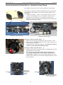
1
SBE 52-MP Moored Profiler CTD and Optional DO Sensor Conductivity, Temperature, Pressure, and Optional Dissolved Oxygen Sensor with Logic Level or RS-232 Interface Standard SBE 52-MP, without Dissolved Oxygen Sensor User’s Manual Sea-Bird Electronics, Inc. 13431 NE 20th Street Bellevue, Washington 98005 USA Telephone: 425/643-9866 Fax: 425/643-9954 E-mail: [email protected] Website: www.seabird.com Manual Version #010, 01/09/13 Firmware Version 2.3 and later Limited Liability Statement Extreme care should be exercised when using or servicing this equipment. It should be used or serviced only by personnel with knowledge of and training in the use and maintenance of oceanographic electronic equipment. SEA-BIRD ELECTRONICS, INC. disclaims all product liability risks arising from the use or servicing of this system. SEA-BIRD ELECTRONICS, INC. has no way of controlling the use of this equipment or of choosing the personnel to operate it, and therefore cannot take steps to comply with laws pertaining to product liability, including laws which impose a duty to warn the user of any dangers involved in operating this equipment. Therefore, acceptance of this system by the customer shall be conclusively deemed to include a covenant by the customer to defend, indemnify, and hold SEA-BIRD ELECTRONICS, INC. harmless from all product liability claims arising from the use or servicing of this system. 2 Manual revision 010 Declaration of Conformity Declaration of Conformity 3 SBE 52-MP Manual revision 010 Table of Contents SBE 52-MP Table of Contents Limited Liability Statement ................................................................ 2 Declaration of Conformity .................................................................. 3 Table of Contents ................................................................................. 4 Section 1: Introduction ........................................................................ 6 About this Manual .............................................................................................6 Quick Start .........................................................................................................6 Unpacking SBE 52-MP......................................................................................7 Section 2: Description of SBE 52-MP................................................. 8 System Description ............................................................................................8 Specifications ...................................................................................................10 Dimensions and Connectors ............................................................................11 Cables and Wiring ...........................................................................................12 Data I/O ...........................................................................................................13 Switching from RS-232 to Logic Level, or Reverse .................................13 Section 3: Power and Communications Test ................................... 14 Software Installation ........................................................................................14 Test Setup ........................................................................................................14 Test ..................................................................................................................15 Section 4: Deploying and Operating SBE 52-MP............................ 19 Sampling Modes ..............................................................................................19 Autonomous Sampling .............................................................................20 Polled Sampling ........................................................................................21 Command Descriptions ....................................................................................22 Data Formats ....................................................................................................37 Data Uploaded from Memory ...................................................................37 Real-Time Data .........................................................................................38 Optimizing Data Quality ..................................................................................40 SBE 52-MP Orientation ............................................................................40 Positioning Relative to Other Instruments ................................................42 Deployment/Recovery Technique and Pump Operation...........................43 Processing Data ........................................................................................43 Deployment ......................................................................................................44 Recovery ..........................................................................................................45 Section 5: Routine Maintenance and Calibration ........................... 46 Corrosion Precautions ......................................................................................46 Connector Mating and Maintenance ................................................................46 Conductivity Cell Maintenance .......................................................................47 Pressure Sensor Maintenance...........................................................................47 Oxygen Sensor Maintenance ...........................................................................47 Replacing Optional Anti-Foulant Devices – Mechanical Design Change .......48 Replacing Optional Anti-Foulant Devices (SBE 49) .......................................49 Sensor Calibration............................................................................................51 Section 6: Troubleshooting................................................................ 53 Problem 1: Unable to Communicate with SBE 52-MP in Seaterm (terminal program) ..........................................................................................................53 Problem 2: Unreasonable Data ........................................................................53 Problem 3: Salinity Lower than Expected .......................................................53 Glossary .............................................................................................. 54 4 Manual revision 010 Table of Contents SBE 52-MP Appendix I: Functional Description and Circuitry........................ 55 Sensors .............................................................................................................55 Sensor Interface ...............................................................................................55 Appendix II: Electronics Disassembly/Reassembly ........................ 56 Appendix III: Command Summary ................................................. 57 Appendix IV: AF24173 Anti-Foulant Device .................................. 60 Appendix V: Replacement Parts ...................................................... 64 Appendix VI: Manual Revision History .......................................... 65 Index .................................................................................................... 66 5 Manual revision 010 Section 1: Introduction SBE 52-MP Section 1: Introduction This section includes contact information, Quick Start procedure, and photos of a standard SBE 52-MP shipment. About this Manual This manual is to be used with the SBE 52-MP Moored Profiler CTD and DO Sensor. It is organized to guide the user from installation through operation and data collection. We’ve included detailed specifications, command descriptions, maintenance and calibration information, and helpful notes throughout the manual. Sea-Bird welcomes suggestions for new features and enhancements of our products and/or documentation. Please contact us with any comments or suggestions ([email protected] or 425-643-9866). Our business hours are Monday through Friday, 0800 to 1700 Pacific Standard Time (1600 to 0100 Universal Time) in winter and 0800 to 1700 Pacific Daylight Time (1500 to 0000 Universal Time) the rest of the year. Quick Start Follow these steps to get a Quick Start using the SBE 52-MP. The manual provides step-by-step details for performing each task: 1. Test power and communications (Section 3: Power and Communications Test). Establish setup and sampling parameters. 2. Deploy the 52-MP (Section 4: Deploying and Operating SBE 52-MP): A. Install I/O cable connector and locking sleeve. Connect other end of cable to moored profiler (controller and power supply). B. Verify hardware and external fittings are secure. C. Remove caps from end of T-C Duct and pump exhaust. D. Deploy 52-MP. E. Apply power. • With 52-MP in water (to avoid running the pump dry), send any character to wake up 52-MP. Then send StartProfile to start sampling. 6 Manual revision 010 Section 1: Introduction SBE 52-MP Unpacking SBE 52-MP Shown below is a typical SBE 52-MP shipment. Standard SBE 52-MP, without Dissolved Oxygen Sensor I/O cable Jackscrew kit Conductivity cell cleaning solution (Triton-X) Software, and Electronic Copies of Software Manuals and User Manual 7 Conductivity cell filling and storage kit Manual revision 010 Section 2: Description of SBE 52-MP SBE 52-MP Section 2: Description of SBE 52-MP This section describes the functions and features of the SBE 52-MP Moored Profiler CTD and Optional DO Sensor, including specifications, dimensions, connectors, and communications. System Description Standard SBE 52-MP, no Dissolved Oxygen Sensor The SBE 52-MP is a conductivity, temperature, depth (pressure) sensor (CTD), designed for moored profiling application in which the instrument makes vertical profile measurements from a device that travels vertically beneath a buoy, or from a buoyant sub-surface sensor package that is winched up and down from a bottom-mounted platform. The 52-MP incorporates pump-controlled, TC-ducted flow to minimize salinity spiking. On typically slow-moving packages (e.g., 20 – 50 cm/sec), its sampling rate of once per second provides good spatial resolution of oceanographic structures and gradients. The standard 52-MP is intended for use in marine or fresh-water environments at depths up to 7000 meters (22,900 feet). The 52-MP can optionally be configured with a Dissolved Oxygen sensor module (SBE 43F). The SBE 43F is a frequency-output version of our SBE 43 Dissolved Oxygen Sensor, and carries the same performance specifications. Shown with optional SBE 43F Dissolved Oxygen Sensor The 52-MP uses the same accurate and stable thermistor, conductivity cell, and pressure sensor that are used in the MicroCAT and Argo Float products. It is easy-to-use, compact, and ruggedly made of titanium and other lowmaintenance (plastic) materials. The operating commands, sent via 0-3.3 volt logic levels or RS-232 interface, are easy to execute with a thirdparty data logger or your own acquisition system. EEPROM-stored calibration coefficients permit data upload in ASCII engineering units (mmho/cm, °C, decibars, ml/l). Alternatively, the user can select to upload data in hexadecimal or binary. The 52-MP is externally powered, and temporarily stores data in static RAM memory. If/when power is removed, any data stored in memory is lost. However, the user-programmable setup is stored in non-volatile RAM, and is retained when power is removed. SBE 52-MP has two sampling modes: • Autonomous sampling - On command, the 52-MP begins autonomous sampling. The 52-MP runs continuously, sampling at one scan per second (1 Hz). It stores the data in memory, and can also transmit the data in realtime. It can bin average the data, and store the bin averaged data in memory in addition to the unaveraged data. On command (typically, at the end of each profile), the data in memory is uploaded. • Polled sampling – On command, the SBE 52-MP takes one sample and transmits the data in real-time. 8 Manual revision 010 Section 2: Description of SBE 52-MP SBE 52-MP The 52-MP’s integral pump runs while the instrument is sampling, providing the following advantages over a non-pumped system: • Improved conductivity and oxygen response – The pump brings a new water sample into the system at a constant flow rate, fixing the sensors’ time constants to ensure maximum dynamic accuracy, and flushes the previously sampled water from the conductivity cell and oxygen sensor plenum. For polled sampling, pump run time for best dissolved oxygen accuracy is a function of temperature and pressure, and is automatically determined by the 52-MP (55 seconds, maximum). • Reduced fouling – When not sampling, the U-shaped flow path and pump impeller restrict flow, maintaining an effective concentration of antifoulant inside the conductivity cell to minimize fouling. A standard 52-MP is supplied with: Note: The 52-MP’s pump is not designed to be used to pump water through sensors other than the conductivity cell and optional integrated dissolved oxygen sensor. Other sensors on your moored profiler requiring pumped water need a separate pump. • Titanium housing for depths to 7000 meters (22,900 feet) • Conductivity, temperature, and pressure (offered in eight full scale ranges from 20 to 7000 decibars) sensors • Integrated T-C Duct and internal pump for flow-controlled conductivity, temperature, and dissolved oxygen sensor response • Anti-foulant device fittings and expendable Anti-Foulant Devices • RS-232 or 0 – 3.3 volt logic level interface (factory configured) • XSG 4-pin I/O bulkhead connector • IE-55 bulkhead connector for optional SBE 43F Dissolved Oxygen Sensor • 3/8-16 locator/mounting hole in the sensor end cap, to assist in mounting to a McLane MMP moored profiler 52-MP options include: Note: See Seaterm’s Help files. • Plastic housing for depths to 600 meters (1960 feet) in lieu of titanium housing • SBE 43F Dissolved Oxygen Sensor • Wet-pluggable MCBH connector in lieu of standard (XSG) I/O connector The 52-MP is supplied with a powerful Windows software package, Seasoft V2, which includes Seaterm, a terminal program for instrument setup and communication. 9 Manual revision 010 Section 2: Description of SBE 52-MP SBE 52-MP Specifications Temperature (°C) Measurement Range -5 to +35 Initial Accuracy 0.002 Typical Stability 0.0002/month Conductivity Pressure 0 to 9 S/m (0 to 90 mmho/cm) 0 to full scale range: 20 / 100 / 350 / 600 / 1000/ 2000 / 3500 / 7000 meters 0.0003 S/m (0.003 mmho/cm) 0.0003 S/m/month (0.003 mmho/cm/month) (expressed in meters of deployment depth capability) 0.1% of full scale range 0.05% of full scale range / year Optional Dissolved Oxygen 120% of surface saturation in all natural waters, fresh and salt 2% of saturation 0.5% per 1000 hours (clean membrane) 0.00005 S/m (0.0005 mmho/cm) (oceanic waters; resolves 0.4 ppm in salinity) Resolution 0.001 0.00007 S/m (0.0007 mmho/cm) 0.002% of full scale range 0.035% of saturation (corresponds to 0.003 ml/l at 0° C and 35 PSU) Ambient pressure to full scale range in 5 steps 1, 4, and 7 ml/l (approximate) at 2, 6, 12, 20, 26, and 30 °C (18 points) (high salinity waters; resolves 0.4 ppm in salinity) 0.00001 S/m (0.0001 mmho/cm) (fresh waters; resolves 0.1 ppm in salinity) Sensor Calibration (measurement outside these ranges may be at slightly reduced accuracy due to extrapolation errors) +1 to +32 zero conductivity (air) plus 2.6 to 6 S/m (26 to 60 mmho/cm) 3 Watts at 7-16 VDC (consult factory for voltage outside this range) Turn-on transient: 300 mA at 10V Power Requirements Quiescent (sleep) state: 0.008 mA at 10V Awake but not sampling: 5.2 mA at 10V Memory Housing Material and Depth Rating Weight Sampling (includes pump): 62 mA at 10V Static RAM; stores up to 28,000 samples of conductivity, temperature, pressure, and dissolved oxygen data. Note: If external power is removed, any data in memory is lost. Standard: 3AL/2.5V Titanium, 7000 meters (22,900 feet) Optional: Plastic, 600 meters (1960 feet) Titanium Housing In air: 5.3 kg (11.8 lbs) In water: 3.7 kg (8.2 lbs) Optional Plastic Housing – In air: 3.2 kg (7.0 lbs) In water: 1.5 kg (3.4 lbs) 10 Manual revision 010 Section 2: Description of SBE 52-MP Dimensions and Connectors DO sensor cable not shown for clarity. Logic Level Note: Tx from the SBE 52-MP is an open collector transistor with a 200-ohm series resistor. The user interface requires a pull-up resistor to their supply voltage; typical resistor value is 3300 ohm. Oxygen Sensor Note: The 52-MP’s optional oxygen sensor may be rotated 180° if desired for your application. However, you must rotate the entire oxygen sensor assembly, including the plenum. To do this: 1. Disconnect the Tygon tubing from the pump exhaust on the sensor end cap. Disconnect the oxygen sensor cable from the sensor end cap bulkhead connector. 2. Remove the screws attaching the sensor guard to the sensor end cap. Carefully remove the sensor guard, along with the attached oxygen sensor and plumbing, from the 52-MP. 3. Disconnect the Tygon tubing on both sides of the oxygen plenum. 4. Remove the screws attaching the oxygen plenum to the sensor guard. Rotate the oxygen sensor 180°, reattach to the sensor guard with the screws, and reconnect the Tygon tubing on both sides of the plenum. 5. Carefully replace the sensor guard, along with the attached oxygen sensor and plumbing, on the 52-MP. Replace the screws attaching the sensor guard to the sensor end cap. 6. Reconnect the oxygen sensor cable to the sensor end cap bulkhead connector. Reconnect the Tygon tubing to the pump exhaust on the sensor end cap. 11 SBE 52-MP Manual revision 010 Section 2: Description of SBE 52-MP Cables and Wiring 12 SBE 52-MP Manual revision 010 Section 2: Description of SBE 52-MP SBE 52-MP Data I/O Note: Seaterm has not been revised to explicitly include the 52-MP. If your 52-MP has an RS-232 interface, or using a logic level to RS-232 converter with a 52-MP that has a logic level interface, select the SBE 49 in Seaterm’s Configure menu – the SBE 49 uses the same data bits, stop bit, and parity. The SBE 52-MP receives setup instructions and outputs data and diagnostic information via a 0- 3.3 volt logic level link or RS-232 interface (factory configured). It is factory-configured for 9600 baud, 8 data bits, 1 stop bit, and no parity. If you want to set up a 52-MP that has been configured with the logic level interface via an RS-232 interface (for example, via a computer RS-232 port), you will require a converter to perform the logic level to RS-232 conversion. Sea-Bird can supply an interface box, PN 90488.1, which provides logic level input to RS-232 conversion. Alternatively, you can supply your own converter. Switching from RS-232 to Logic Level, or Reverse The SBE 52-MP is factory-configured to the requested communication interface. You can switch the configuration by sending a command and moving two jumpers on the digital PCB. Note: See Appendix II: Electronics Disassembly/Reassembly to access the PCB. 1. Send *RS232=Y to switch from logic level to RS-232, or send *RS232=N to switch from RS-232 to logic level. Note that you must send the appropriate command before you move the jumper. 2. On the digital PCB (10331A), move the JP1 and JP2 jumpers as shown in the table below: Interface JP1 JP2 1-2 1-2 Logic Level 2-3 2-3 RS-232 13 Manual revision 010 Section 3: Power and Communications Test SBE 52-MP Section 3: Power and Communications Test This section describes software installation and the pre-check procedure for preparing the SBE 52-MP for deployment. The power and communications test will verify that the system works, prior to deployment. Software Installation Notes: • Help files provide detailed information on the software. • If your 52-MP has an RS-232 interface, or using a logic level to RS-232 converter with a 52-MP that has a logic level interface: - Seaterm can be used to set up the 52-MP. - Alternatively, it is possible to use the 52-MP without Seaterm by sending direct commands from a dumb terminal or terminal emulator, such as Windows HyperTerminal. • Sea-Bird supplies the current version of our software when you purchase an instrument. As software revisions occur, we post the revised software on our FTP site. See our website (www.seabird.com) for the latest software version number, a description of the software changes, and instructions for downloading the software from the FTP site. Seasoft V2 was designed to work with a PC running Windows XP service pack 2 or later, Windows Vista, or Windows 7. If not already installed, install Sea-Bird software programs on your computer using the supplied software CD: 1. Insert the CD in your CD drive. 2. Install software: Double click on SeasoftV2_date.exe (date is the date that version of the software was created). Follow the dialog box directions to install the software. The installation program allows you to install the desired components. Install all the components, or just install Seaterm (terminal program). The default location for the software is c:\Program Files\Sea-Bird. Within that folder is a sub-directory for each program. Test Setup 1. Remove the dummy plug and install the I/O cable: A. By hand, unscrew the locking sleeve from the 52-MP’s I/O connector. If you must use a wrench or pliers, be careful not to loosen the I/O connector instead of the locking sleeve. B. Remove the dummy plug from the 52-MP’s I/O connector by pulling the plug firmly away from the connector. Locking sleeve C. Standard Connector - Install the Sea-Bird I/O cable connector, aligning the raised bump on the side of the connector with the large pin (pin 1 - ground) on the 52-MP. OR MCBH Connector – Install the cable connector, aligning the pins. Dummy plug 2. Connect the other end of the I/O cable to your controller and power supply. See Dimensions and Connectors in Section 2: Description of SBE 52-MP for pinout details. 14 Manual revision 010 Section 3: Power and Communications Test SBE 52-MP Test Notes: • Seaterm can be used to set up the 52-MP only If you have a 52-MP with an RS-232 interface or are using a logic level to RS-232 converter with a 52-MP with a logic level interface. • See Seaterm’s help files. 1. Double click on SeaTerm.exe. If this is the first time the program is used, the setup dialog box may appear: SBE49 Note: Seaterm has not been revised to explicitly include the 52-MP. When using Seaterm with the 52-MP, select the SBE 49 – the SBE 49 uses the same data bits, stop bit, and parity. Select the instrument type (SBE 49) and the computer COM port for communication with the 52-MP. Click OK. 2. The main screen looks like this: Menus Toolbar Command/Data Echo Area Status bar Note: There is at least one way, and as many as three ways, to enter a command: • Manually type a command in Command/Data Echo Area • Use a menu to automatically generate a command • Use a Toolbar button to automatically generate a command Instrument EPROM version • • Note: Once the system is configured and connected (Steps 3 through 4 below), to update the Status bar: • on the Toolbar, click Status; or • from the Utilities menu, select Instrument Status. Seaterm sends the status command, which displays in the Command/Data Echo Area, and updates the Status bar. Computer COM port Instrument • • (not applicable to 52-MP) Capture to file status – grayed out if not capturing Baud rate, data bits, stop bits, and parity Menus – Contains tasks and frequently executed instrument commands. Toolbar – Contains buttons for frequently executed tasks and instrument commands. All tasks and commands accessed through the Toolbar are also available in the Menus. To display or hide the Toolbar, select View Toolbar in the View menu. Grayed out Toolbar buttons are not applicable. Command/Data Echo Area – Displays the 52-MP’s response to a command. Additionally, commands can be manually typed in this area, from the available commands for the 52-MP. Note that the 52-MP must be awake for it to respond to a command (use Connect on the Toolbar or send any character to wake up the 52-MP). Status bar – Provides status information. To display or hide the Status bar, select View Status bar in the View menu. 15 Manual revision 010 Section 3: Power and Communications Test SBE 52-MP Following are the Toolbar buttons applicable to the 52-MP: Toolbar Button Description Equivalent Command* (send any character) Re-establish communications with 52-MP. Computer responds with S> prompt. Display instrument setup and status Status (configuration and setup parameters, DS number of samples in memory, etc.). Display calibration coefficients Coefficients (conductivity, temperature, pressure, DC and optional oxygen). Capture instrument responses on screen to file; useful for diagnostics. File has .cap Capture extension. Capture status displays in — Status bar. Press Capture again to turn off capture. Perform one or more diagnostic tests on 52-MP. Diagnostic test(s) accessed in DS, DC, Diagnostics this manner are non-destructive – and TS they do not write over any existing instrument settings. Interrupt and end current activity, such as (press Esc key or Stop sampling or diagnostic test. Ctrl C) Free computer COM port used to Disconnect communicate with 52-MP. COM port can — then be used by another program. *See Command Descriptions in Section 4: Deploying and Operating SBE 52-MP. Connect 16 Manual revision 010 Section 3: Power and Communications Test Note: Seaterm has not been revised to explicitly include the 52-MP. Select the SBE 49 in Seaterm’s Configure menu – the SBE 49 uses the same data bits, stop bit, and parity as the 52-MP. 3. In the Configure menu, select SBE 49. The dialog box looks like this: Interface for communication between computer and 52-MP. Computer COM port, baud rate, data bits, and parity for communication between computer and 52-MP. 52-MP only communicates at 9600 baud. Notes: • Seaterm’s baud rate must be the same as the 52-MP baud rate (9600). • When you click OK, Seaterm saves the Configuration Options settings to the SeaTerm.ini file in your Windows directory. SeaTerm.ini contains the last saved settings for each instrument. When you open Seaterm and select the desired instrument (SBE 37, 49, etc.) in the Configure menu, the Configuration Options dialog box shows the last saved settings for that instrument. SBE 52-MP Make the selections in the Configuration Options dialog box: • COMM Port: COM 1 through COM 10, as applicable • Baud Rate: 9600 (only valid baud rate for 52-MP) • Data Bits: 8 • Parity: None • Mode: RS-232 (Full Duplex) Click OK to save the settings. 4. Click Connect on the Toolbar or send any character. Seaterm tries to connect to the 52-MP. When it connects, the display looks like this: S> This shows that correct communications between the computer and the 52-MP has been established. If the system does not respond with the S> prompt: • Click Connect (or send any character) again. • Verify the SBE 49 was selected in the Configure menu and the settings were entered correctly in the Configuration Options dialog box. • Check cabling between the computer and 52-MP. 17 Manual revision 010 Note: The 52-MP does not echo characters received from the computer. Therefore, the commands you send (for example, DS) will not appear in the Seaterm display. CAUTION: Sending the PTS command causes the pump to turn on – depending on temperature and pressure, the pump may run for up to 55 seconds (see Polled Sampling Commands in Section 4: Deploying and Operating SBE 52-MP). Do not run the pump dry. The pump is water lubricated; running it without water (except for very short periods) will damage it. If testing the 52-MP in dry conditions, fill the inside of the pump head with water via the pump exhaust tubing. This will provide enough lubrication to prevent pump damage during testing. Section 3: Power and Communications Test 5. SBE 52-MP Display 52-MP status information by clicking Status on the Toolbar or typing DS and pressing the Enter key. The display looks like this: SBE 52 MP CTD 2.3 SERIAL NO. 0004 DO installed = yes output CTDO when profiling stop profile when pressure is less than = 5.0 decibars automatic bin averaging when p < 5.0 disabled number of samples = 10050 number of bins = 39 top bin interval = 10 top bin size = 10 top bin max = 100 middle bin interval = 50 middle bin size = 50 middle bin max = 1000 bottom bin interval = 100 bottom bin size = 100 do not include two transition bins oxygen frequency multiplier = 1.00 6. Command the 52-MP to take a sample by typing PTS or TS and pressing the Enter key. The display looks like this: 35.4789, where 6.9892, 182.25, 6.768 35.4789 = conductivity (mmho/cm) 6.9892 = temperature (degrees Celsius) 182.25 = pressure (decibars) 6.768 = dissolved oxygen (ml/l) These numbers should be reasonable for the present environment of your instrument (for example, in air, in fresh water, or in seawater). Note that if DO installed = no, the 52-MP outputs 0.000 for the dissolved oxygen value. The 52-MP is ready for programming and deployment. 18 Manual revision 010 Section 4: Deploying and Operating SBE 52-MP SBE 52-MP Section 4: Deploying and Operating SBE 52-MP This section includes discussions of: Note: Help files contain detailed information on Seaterm. • Sampling modes, including pump operation and example commands • Command descriptions • Data formats • Optimizing data quality • Deployment • Recovery Sampling Modes The SBE 52-MP has two sampling modes for obtaining data: • Autonomous sampling (typical use) • Polled sampling Descriptions and examples of the sampling modes follow. Note that the 52-MP’s response to each command is not shown in the examples. Review the operation of the sampling modes and the commands described in Command Descriptions before setting up your system. 19 Manual revision 010 Section 4: Deploying and Operating SBE 52-MP SBE 52-MP Autonomous Sampling Note: The 52-MP does not echo characters received from the computer. Therefore, the commands you send (for example, DS) will not appear in the Seaterm display. Commands are shown in the example below for illustration only. The SBE 52-MP runs continuously, sampling data at 1 scan per second (1 Hz), and storing data to memory. The 52-MP can also transmit in real-time: • pressure (decibars); • sample number data; • pressure (decibars) and sample number data; • conductivity (mmho/cm), temperature (°C), pressure (decibars), and optional oxygen (Hz); or • conductivity (Hz), temperature (A/D counts), pressure (A/D counts), pressure temperature (A/D counts), and optional oxygen (Hz) Example 1: Autonomous Sampling Setup (user input in bold) 52-MP with RS-232 interface, or using logic level to RS-232 converter with 52-MP that has logic level interface In the lab, using Seaterm, set up 52-MP to sample on the upcast from 1000 m to 10 m, to stop sampling automatically at 10 m, and to calculate bins automatically when it stops sampling. For bin averaging: set up a top section from 10 to 100 m with 10 m bins, a middle section from 100 to 300 m with 20 m bins, and a bottom section from 300 to 1000 m with 50 m bins, and also calculate transition bins. Set up 52-MP to output real-time pressure. Verify setup with status command. Remove power. (Apply power, then send any character to wake up.) S>PCUTOFF=10 S>AUTOBINAVG=Y S>TOP_BIN_INTERVAL=10 S>TOP_BIN_SIZE=10 S>TOP_BIN_MAX=100 S>MIDDLE_BIN_INTERVAL=20 S>MIDDLE_BIN_SIZE=20 S>MIDDLE_BIN_MAX=300 S>BOTTOM_BIN_INTERVAL=50 S>BOTTOM_BIN_SIZE=50 S>INCLUDETRANSITIONBIN=Y S>OUTPUTPRESSURE=Y S>DS (to verify setup) (Remove power.) Program controller to monitor real-time pressure output to determine when autonomous sampling has stopped, and to send data upload commands (DD for all data and DA for bin averaged data) after some delay to allow time for the 52-MP to calculate the bin averages. When ready to begin sampling: (Put 52-MP in water, send down to 1000 m, apply power, then send any character to wake up 52-MP.) S>STARTPROFILE (Autonomous sampling stops automatically at 10 m (PCutoff=), and 52-MP calculates bins. Controller sends DD (unaveraged data) and DA (bin averaged data) to upload data.) 20 Manual revision 010 Section 4: Deploying and Operating SBE 52-MP SBE 52-MP Polled Sampling Note: The 52-MP does not echo characters received from the computer. Therefore, the commands you send (for example, DS) will not appear in the Seaterm display. Commands are shown in the example below for illustration only. On command, the SBE 52-MP takes one sample and transmits the data real-time. • PTS command – 52-MP runs the pump before sampling, ensuring a conductivity and optional dissolved oxygen measurement based on a fresh water sample. Oxygen sensor response time, and the corresponding length of time the pump needs to run before taking a sample, is dependent on temperature and pressure. Oxygen sensor response time increases with increasing pressure and decreasing temperature. Therefore, the 52-MP takes a preliminary measurement of temperature and pressure (but does not store the preliminary values in memory), uses those values to calculate the required pump time, runs the pump, and then takes a fresh measurement of all parameters. • TS or TSR command – 52-MP pump does not turn on automatically before sampling. To run the pump before taking a sample, send PumpOn to turn the pump on before sending TS or TSR. Send PumpOff to turn the pump off after taking the sample. Example: Polled Sampling (user input in bold) Example 1: Apply power and send any character to wake up 52-MP. Command 52-MP to take a sample and output data in ASCII engineering units, using PTS command (automatically runs pump for sample). Remove power. Repeat as desired. (Apply power, then send any character to wake up 52-MP.) S>PTS (Remove power.) Example 2: Apply power and send any character to wake up 52-MP. Command 52-MP to turn pump on, take a sample and output raw data, and turn pump off. Remove power. Repeat as desired. (Apply power, then send any character to wake up 52-MP.) S>PUMPON S>TSR S>PUMPOFF (Remove power.) 21 Manual revision 010 Section 4: Deploying and Operating SBE 52-MP SBE 52-MP Command Descriptions This section describes commands and provides sample outputs. See Appendix III: Command Summary for a summarized command list. When entering commands: • Input commands to the 52-MP in upper or lower case letters and register commands by pressing the Enter key. • The 52-MP sends ?CMD if an invalid command is entered. • If the system does not return an S> prompt after executing a command, press the Enter key to get the S> prompt. • Establish communications by pressing Connect on the Toolbar or sending any character to get the S> prompt. • If the 52-MP is transmitting data and you want to stop it, send StopProfile, click Stop on the Toolbar, or type Ctrl Z. Press the Enter key or send any character to get the S> prompt. • The 52-MP responds only to SLP and StopProfile while sampling. Entries made with the commands are permanently stored in the 52-MP in nonvolatile RAM and remain in effect until you change them. Removing power does not affect the user-programmed setup. 22 Manual revision 010 Section 4: Deploying and Operating SBE 52-MP SBE 52-MP Status Command DS Display operating status and setup parameters. Equivalent to Status on Toolbar. List below includes, where applicable, command used to modify parameter. • • • • • • • • • • • • • • • • • firmware version, serial number oxygen sensor enabled? [SetDOInstalled=] real-time output enabled? [OutputPressure=, OutputCTDO=, OutputCTDORaw=, OutputSN=] cutoff pressure to stop autonomous sampling [PCutoff=] automatically average stored data into bins when profile is stopped because pressure < PCutoff? [AutoBinAvg=] number of samples in memory number of bins in memory spacing between bins for top bin [Top_Bin_Interval=] size of each top bin [Top_Bin_Size=] maximum pressure for top section [Top_Bin_Max=] spacing between bins for middle bin [Middle_Bin_Interval=] size of each middle bin [Middle_Bin_Size=] maximum pressure for middle section [Middle_Bin_Max=] spacing between bins for bottom bin [Bottom_Bin_Interval=] size of each bottom bin [Bottom_Bin_Size=] calculate transition bin between top and middle bin and between middle and bottom bin? [IncludeTransitionBin=] oxygen frequency multiplier [OxMultiplier=] Example: Status (DS) command (user input in bold; command used to modify parameter in parentheses) S>DS SBE 52 MP CTD 2.3 SERIAL NO. 0004 DO installed = yes [SetDOInstalled=] output CTDO when profiling [OutputPressure=, OutputCTDO=, OutputCTDORaw=, OutputSN=] stop profile when pressure is less than = 5.0 decibars [PCutoff=] automatic bin averaging when p < 5.0 disabled [AutoBinAvg=] number of samples = 10050 number of bins = 39 top bin interval = 10 [Top_Bin_Interval=] top bin size = 10 [Top_Bin_Size=] top bin max = 100 [Top_Bin_Max=] middle bin interval = 50 [Middle_Bin_Interval=] middle bin size = 50 [Middle_Bin_Size=] middle bin max = 1000 [Middle_Bin_Max=] bottom bin interval = 100 [Bottom_Bin_Interval=] bottom bin size = 100 [Bottom_Bin_Size=] do not include two transition bins [IncludeTransitionBin=] oxygen frequency multiplier = 1.00 [OxMultiplier=] 23 Manual revision 010 Section 4: Deploying and Operating SBE 52-MP SBE 52-MP Setup Commands Note: If SetDOInstalled=Y but there is no oxygen sensor installed, the 52-MP will output bogus values for DO data. Note: If OverWriteMem=Y, and you have filled and started to overwrite the memory, uploading all data using DD (engineering units), DDH (Hex), or DDB (Binary) will provide newer data followed by older data. Similarly, if uploading all the bin averaged data in memory, the newer data will be followed by the older data. Example: SBE 52-MP overwrote first 10,000 samples of the 28,000 sample memory. Samples 1 – 10,000 are data that was measured after samples 10,001 – 28,000. Note: The 52-MP enters quiescent state automatically (without sending QS) if it is not sampling and does not receive a command for 2 minutes. SetDOInstalled=x x=Y: Optional DO sensor is installed. X=N: Optional DO sensor is not installed; 52-MP outputs all zeroes for DO data. PCutoff=x x= pressure cutoff (decibars). 52-MP automatically stops autonomous sampling when pressure is less than PCutoff. OverWriteMem=x x=Y: Reset sample number to 0 and bin number to 0 when memory fills. 52-MP continues autonomous sampling, and overwrites earlier data in memory when memory fills. x=N: Do not reset sample number to 0 and bin number to 0 when memory fills. 52-MP automatically stops autonomous sampling when memory fills. InitProfile Do not use unless all previous data has been uploaded. InitProfile sets sample number for first sample to 0 and bin number for first bin to 0. This resets 52-MP to start saving data to beginning of memory, overwriting previous data in memory and making entire memory available for recording. Use of InitProfile is not required if you will use StartProfile or StartProfileN to start autonomous sampling; these commands automatically reset sample number and bin number to 0 before beginning sampling. OxMultiplier=x x= oxygen sensor frequency multiplier, 0 < OxMultiplier < 4.0. Typical value approximately 0.25. Multiplies measured frequency by a factor to convert to sensor output. See configuration sheet for appropriate value for your instrument. QS Quit session and place 52-MP in quiescent (sleep) state. Power to digital and analog electronics is turned off. Memory retention is not affected. 24 Manual revision 010 Section 4: Deploying and Operating SBE 52-MP SBE 52-MP Real-Time Output Commands Real-time output can be one of the following: • Pressure (OutputPressure=Y) • Sample number (OutputSN=Y) • Sample number and pressure (OutputSN=Y and OutputPressure=Y) – output is sample number, pressure • Conductivity, temperature, and pressure in engineering units; optional oxygen in raw units (OutputCTDO=Y) • Conductivity, temperature, pressure, pressure temperature, and optional oxygen in raw units (OutputCTDORaw=Y) OutputPressure=x Notes: If outputting real-time data (OutputPressure=Y, OutputCTDO=Y, OutputCTDORaw=Y, or OutputSN=Y), the 52-MP measures all parameters, and then transmits the real-time data while making the next measurement. x=Y: Output real-time pressure in ASCII engineering units (ppppp.pp decibars) while autonomous sampling. x=N: Do not output real-time pressure while autonomous sampling. OutputSN=x x=Y: Output real-time sample number (5 digits) while autonomous sampling. x=N: Do not output real-time sample number while autonomous sampling. OutputCTDO=x x=Y: Output real-time conductivity, temperature, and pressure in ASCII engineering units, and optional oxygen frequency (ccc.cccc mmho/cm, ttt.tttt °C, ppppp.pp decibars, ooooo.o Hz) while autonomous sampling. x=N: Do not output real-time CTDO data while autonomous sampling. OutputCTDORaw=x x=Y: Output raw real-time data (conductivity cccc.ccc Hz, temperature tttttt.t A/D counts, pressure pppppp.p A/D counts, pressure temperature vvvvvv.v A/D counts, optional oxygen ooooo.o Hz) while autonomous sampling. x=N: Do not output raw real-time CTDO data while autonomous sampling. 25 Manual revision 010 Section 4: Deploying and Operating SBE 52-MP SBE 52-MP Bin Averaging Commands The SBE 52-MP can average data into bins, based on pressure ranges, after a profile is completed. The 52-MP processes approximately 52 scans per second when calculating the bins. The 52-MP stores bin averaged data in a separate part of the memory than where the full data set is stored. The user can upload the full data set, the bin averaged data, or both. The algorithm the 52-MP uses for bin averaging is described below. For each bin: BinMin = bin center value - (bin size / 2) BinMax = bin center value + (bin size / 2) 1. Add together valid data for scans with BinMin < pressure < BinMax. 2. Divide the sum by the number of valid data points to obtain the average. 3. Interpolate as follows, and write the interpolated value to memory: Pp = average pressure of previous bin Xp = average value of variable in previous bin Pc = average pressure of current bin Xc = average value of variable in current bin Pi = center value for pressure in current bin Xi = interpolated value of variable (value at center pressure Pi ) = ( (Xc - Xp) * (Pi - Pp) / (Pc - Pp) ) + Xp 4. Repeat Steps 1 through 3 for each variable. 5. Compute the center value and Repeat Steps 1 through 4 for the next bin. Values for the first bin are interpolated after averages for the second bin are calculated; values from the next (second) bin instead of the previous bin are used in the equations. Starting Bin Averaging AutoBinAvg=x x=Y: Automatically average stored data into bins when autonomous sampling is stopped because pressure < PCutoff. x= N: Do not automatically average stored data into bins. BinAverage Average stored data into bins now. Send StopProfile to stop autonomous sampling before sending this command. 26 Manual revision 010 Section 4: Deploying and Operating SBE 52-MP SBE 52-MP Bin Averaging Commands (continued) Setting Bin Averaging Parameters The 52-MP allows you to define a top, middle, and bottom section of the profile; each section can have different bin sizes and bin intervals. In addition, it allows you to define a transition bin between the top and middle section, and between the middle and bottom section. 27 Manual revision 010 Section 4: Deploying and Operating SBE 52-MP SBE 52-MP Bin Averaging Commands (continued) Top_Bin_Interval=x x= spacing between bin centers for top section (decibars). Example: If top bin interval is 10 db, top section bin centers are at 0, 10, 20, etc. Top_Bin_Size=x x= bin size for top section (decibars). Scans from bin center to (± Top_Bin_Size/2) are included in data for bin. For typical use, set Top_Bin_Size equal to Top_Bin_Interval. Example 1: If interval is 10 db and bin size is 10 db, first bin is centered at 10 and goes from 5 to 15, second bin is centered at 20 and goes from 15 to 25, etc. Example 2: If interval is 10 db and bin size is 8 db, first bin is centered at 10 and goes from 6 to 14, second bin is centered at 20 and goes from 16 to 24, etc. Top_Bin_Max=x x= maximum pressure for top section (db). For best results, set so center of last top bin is at Top_Bin_Max. Middle_Bin_Interval=x x= spacing between bin centers for middle section (decibars). Example: If top section maximum pressure is 100 db and middle bin interval is 20 db, middle section bin centers are at 120, 140, etc. Middle_Bin_Size=x x= bin size for middle section (decibars). Scans from bin center to (± Middle_Bin_Size/2) are included in data for bin. For typical use, set Middle_Bin_Size equal to Middle_Bin_Interval. Example 1: If top section maximum pressure is 100 db, middle bin interval is 20 db, and middle bin size is 20 db, first middle bin is centered at 120 and goes from 110 to 130, second middle bin is centered at 140 and goes from 130 to 150, etc. Example 2: If top section maximum pressure is 100 db, middle bin interval is 20 db, and middle bin size is 16 db, first middle bin is centered at 120 and goes from 112 to 128, second middle bin is centered at 140 and goes from 132 to 148, etc. Middle_Bin_Max=x x= maximum pressure for middle section (decibars). For best results, set so center of last middle bin is at Middle_Bin_Max. 28 Manual revision 010 Section 4: Deploying and Operating SBE 52-MP SBE 52-MP Bin Averaging Commands (continued) Bottom_Bin_Interval=x x= spacing between bin centers for bottom section (decibars). Example: If middle section maximum pressure is 1000 db and bottom bin interval is 50 db, bottom section bin centers are at 1050, 1100, etc. Bottom_Bin_Size=x x= bin size for bottom section (decibars). Scans from bin center to (± Bottom_Bin_Size/2) are included in data for bin. For typical use, set Bottom_Bin_Size equal to Bottom_Bin_Interval. Example 1: If middle section maximum pressure is 1000 db, bottom bin interval is 50 db, and bottom bin size is 50 db, first bottom bin is centered at 1050 and goes from 1025 to 1075, second bottom bin is centered at 1100 and goes from 1075 to 1125, etc. Example 2: If middle section maximum pressure is 1000 db, bottom bin interval is 50 db, and bottom bin size is 40, first bottom bin is centered at 1050 and goes from 1030 to 1070, second bottom bin is centered at 1100 db and goes from 1080 to 1120, etc. IncludeTransitionBin=x x=Y: Calculate transition bin between top and middle section, and between middle and bottom section. Transition bins are: (last top bin center + Top_Bin_Interval/2) to (last top bin center + Middle_Bin_Interval/2) and (last middle bin center + Middle_Bin_Interval/2) to (last middle bin center + Bottom_Bin_Interval/2) x= N: Do not calculate transition bins. Example: Top_Bin_Interval=Top_Bin_Size=10 (db) Middle_Bin_Interval=Middle_Bin_Size=100 (db) Top_Bin_Max=100 (db) Looking at what happens between the top and middle section if there is no transition bin: Section Bin Center Bin Range ... ... Top 90 85 – 95 100 95 - 105 200 150 – 250 Middle 300 250 – 350 ... ... You can see that there is a gap in the bins, from 105 to 150 db. By including the transition bin, you can cover the gap. Start of transition bin = last top bin center + Top_Bin_Interval/2 = 100 + 10 / 2 = 105 db End of transition bin = last top bin center + Middle_Bin_Interval/2 = 100 + 100 / 2 = 150 db 29 Manual revision 010 Section 4: Deploying and Operating SBE 52-MP SBE 52-MP Autonomous Sampling Commands CAUTION: Sending StartProfile, StartProfileN, ResumeProfile, or ResumeProfileN causes the pump to turn on. Do not run the pump dry. The pump is water lubricated; running it without water (except for very short periods) will damage it. If testing your system in dry conditions, fill the inside of the pump head with water via the pump exhaust tubing. This will provide enough lubrication to prevent pump damage during testing. Note: Sending StartProfile and StartProfileN resets the 52-MP to start saving data to the beginning of memory, overwriting previous data in memory and making the entire memory available for recording. Notes: • You may need to send StopProfile several times to get the 52-MP to respond. • Autonomous sampling stops automatically if: pressure is less than the pressure cutoff, PCutoff, or 52-MP memory is full and OverWriteMem=N (can hold up to 28,000 samples; at 1 second/sample, this corresponds to 28,000 seconds of autonomous sampling). Autonomous sampling directs the 52-MP to turn on the pump and sample conductivity, temperature, pressure, and optional oxygen continuously (at 1 Hz). The pump runs at fast speed for 2.5 seconds, and then runs continuously at slow speed. Fast speed removes any debris from the system and rapidly brings in new water; once the system is cleared, the slow speed provides adequate flushing of the system while minimizing the power required. The 52-MP can be set up to transmit in real-time: pressure; sample number; sample number and pressure; or conductivity, temperature, pressure, and optional oxygen in converted or raw units (see Real-Time Output Commands above). Do not remove power from the 52-MP before uploading data; if power is removed, any data in memory will be lost. StartProfile Do not use unless all previous data has been uploaded. Set sample number for first sample to 0 and bin number for first bin to 0, start pump, and start autonomous sampling. StartProfileN Do not use unless all previous data has been uploaded. Set sample number for first sample to 0 and bin number for first bin to 0, start pump and let pump run for N seconds, and then (with pump continuing to run) start autonomous sampling. ResumeProfile Start pump and start autonomous sampling; new data is stored to memory after previously saved data. ResumeProfileN Start pump and let pump run for N seconds, then (with pump continuing to run) start autonomous sampling; new data is stored to memory after previously saved data. StopProfile Stop pump and stop autonomous sampling. Press Enter key to get S> prompt before entering StopProfile. SLP Send last sample of pressure data from memory in ASCII engineering units (ppppp.pp decibars). 52-MP responds to SLP only while autonomous sampling. 30 Manual revision 010 Section 4: Deploying and Operating SBE 52-MP SBE 52-MP Autonomous Sampling Commands (continued) DTDP Transmit last calculated value for dt/dp. 52-MP calculates dt/dp each time you send StopProfile, if autonomous sampling was started with ResumeProfile or ResumeProfileN. dt/dp = (t – t OLD) / (p OLD – p) where t = temperature from last sample before receiving StopProfile; p = pressure from last sample before receiving StopProfile; t OLD = temperature from last sample before receiving previous StopProfile; p OLD = pressure from last sample before receiving previous StopProfile. Example: You plan to deploy the 52-MP on a deep mooring, and have it sample on upcast from 7000 db to 5 db. However, to conserve power, you don’t want to sample continuously through deep water, where measured parameters are likely to change very little. You program the controller to send StartProfile at 7000 db, then StopProfile at 6980 db; ResumeProfile at 6900 db, then StopProfile and DTDP at 6880 db; ResumeProfile at 6800 db, then StopProfile and DTDP at 6780 db; etc. Each time you send StopProfile, the 52-MP calculates dt/dp, which is then transmitted to the controller when you send DTDP. You program the controller to check for when dt/dp reaches a threshold value (i.e., indicating that the temperature is changing significantly) and to sample continuously after that point is reached (i.e., the controller does not send StopProfile beyond that point). You have programmed the 52-MP with PCutoff=5 and AutoBinAvg=Y, so autonomous sampling stops automatically at 5 db and bins for the entire profile are calculated when the 52-MP reaches 5 db. Fast Pressure Sampling Command TFP Measure pressure at approximately 4 Hz (0.25 seconds/sample), transmit ASCII converted data (pppp.ppp decibars), one measurement per line, followed by a carriage return and line feed. Data is not stored in SRAM memory. Press Esc key or Stop on Toolbar to stop fast pressure sampling. 31 Manual revision 010 Section 4: Deploying and Operating SBE 52-MP SBE 52-MP Data Upload Commands See Data Formats for details. All Data (unaveraged) Note: If OverWriteMem=Y, and you have filled and started to overwrite the memory, uploading all data using DD (engineering units), DDH (Hex), or DDB (Binary) will provide newer data followed by older data. Example: Overwrote first 10,000 samples of the 28,000 sample memory. Samples 1 – 10,000 are data that was measured after samples 10,001 – 28,000. DDN Display number of data samples (unaveraged) in memory (up to 5 characters followed by a carriage return and line feed). DDs,f Upload all data (unaveraged) from sample s to sample f, in ASCII engineering units. If s and f are omitted, all data is uploaded. First sample number is 0. DDHs,f Upload all data (unaveraged) from sample s to sample f, in Hex. If s and f are omitted, all data is uploaded. First sample number is 0. DDBs,f Upload all data (unaveraged) from sample s to sample f, in binary. If s and f are omitted, all data is uploaded. First sample number is 0. Bin Averaged Data Note: If OverWriteMem=Y, and you have filled and started to overwrite the memory, uploading all bin averaged data using DA (engineering units), DAH (Hex), or DAB (Binary) will provide newer data followed by older data. Example: Assume there are 3,500 bins in the bin averaged portion of the memory when the main memory fills, and that the first 1,000 bins are overwritten. Bins 1 – 1,000 are bin averaged data that was measured after the data in Bins 1,001 – 3,500. DAN Display number of averaged bins in memory (up to 4 characters followed by a carriage return and line feed). NBin Display number of averaged bins in memory (label plus up to 4 characters followed by a carriage return and line feed). Display looks like this: Number of bins = 3500 DAs,f Upload bin averaged data from bin s to bin f, in ASCII engineering units. If s and f are omitted, all data is uploaded. First bin number is 0. DAHs,f Upload bin averaged data from bin s to bin f, in Hex. If s and f are omitted, all data is uploaded. First bin number is 0. DABs,f Upload bin averaged data from bin s to bin f, in binary. If s and f are omitted, all data is uploaded. First bin number is 0. 32 Manual revision 010 Section 4: Deploying and Operating SBE 52-MP SBE 52-MP Polled Sampling Commands CAUTION: Sending PTS causes the pump to turn on. Do not run the pump dry. The pump is water lubricated; running it without water (except for very short periods) will damage it. If testing your system in dry conditions, fill the inside of the pump head with water via the pump exhaust tubing. This will provide enough lubrication to prevent pump damage during testing. PTS Run pump; take 1 sample of all parameters; transmit data in ASCII engineering units (conductivity ccc.cccc mmho/cm, temperature ttt.tttt °C, pressure ppppp.pp decibars, optional oxygen oo.ooo ml/l); and turn pump off. Length of time that pump runs: Oxygen sensor response time, and corresponding length of time pump needs to run before taking sample, is dependent on temperature and pressure. 52-MP takes preliminary measurement of T and P, uses those values to calculate pump time (but does not store T and P values in memory), runs pump, and then takes fresh measurement of all parameters. Pump time increases with increasing P and decreasing T. For example, if: T=0 °C, P=1000 db, total pump time=44.6 sec; T=30 °C, P=0 db, total pump time=9.8 sec. Maximum total pump run time is 55 sec. Total pump time consists of fast speed (remove any debris from the system and rapidly bring in a new water sample) followed by slow speed (provide adequate flushing of system while minimizing power required); 52-MP calculates optimal time for pump to operate at each speed. Note: TS and TSR do not automatically turn the pump on. To get conductivity and optional oxygen from a fresh sample, send PumpOn some time before sending TS or TSR, and then send PumpOff when the data has been received. See the CAUTION above about running the pump dry. TS Take 1 sample of all parameters and transmit data in ASCII engineering units (conductivity ccc.cccc mmho/cm, temperature ttt.tttt °C, pressure ppppp.pp decibars, optional oxygen oo.ooo ml/l). This command does not run pump before sampling. If desired, send a pump command before and after sending TS, to turn pump on and off. TSR Take 1 sample of all parameters and transmit ASCII raw data (conductivity cccc.ccc Hz, temperature tttttt.t A/D counts, pressure pppppp.p A/D counts, pressure temperature vvvvvv.v A/D counts, optional oxygen ooooo.o Hz). This command does not run pump before sampling. If desired, send a pump command before and after sending TSR, to turn pump on and off. FP Take 1 sample of pressure, and transmit data in ASCII engineering units (ppppp.pp decibars). 33 Manual revision 010 Section 4: Deploying and Operating SBE 52-MP SBE 52-MP Pump Commands The pump runs automatically for autonomous sampling, and for the PTS polled sampling command. Use pump commands: • Before sending TS or TSR polled sampling commands, or TC, TCR, TO, or TOR testing commands to obtain pumped conductivity and/or optional oxygen data, or • To test pump. CAUTION: Do not run the pump dry. The pump is water lubricated; running it without water (except for very short periods) will damage it. If testing your system in dry conditions, fill the inside of the pump head with water via the pump exhaust tubing. This will provide enough lubrication to prevent pump damage during testing. PumpOn Turn on pump (fast speed for 2.5 seconds, then slow speed). This is pumping scheme automatically used by 52-MP for autonomous sampling. Fast speed removes any debris from system and rapidly brings in new water sample; once system is cleared, slow speed provides adequate flushing of system while minimizing power required. PumpFast Turn pump on at fast speed. PumpSlow Turn pump on at slow speed. PumpOff Turn pump off. Testing Commands The 52-MP samples and transmits data in ASCII engineering units for 100 samples for each test. Data is not stored in SRAM memory. Press the Esc key or Stop on the Toolbar to stop a test. Note: These commands do not automatically turn on the pump. Thus, they report conductivity and optional oxygen from essentially the same sample of water for all 100 measurements, because the pump does not run but the pump and associated plumbing prevent water from freely flowing through the conductivity cell and dissolved oxygen sensor. To get conductivity and oxygen from fresh samples, send PumpOn before sending a conductivity or oxygen testing command, and then send PumpOff when the test is complete. See the CAUTION above about running the pump dry. TC Measure conductivity, transmit ASCII converted data (cc.ccccc mmho/cm). TT Measure temperature, transmit ASCII converted data (ttt.tttt °C). TP Measure pressure and pressure temperature, transmit ASCII converted data (pppp.ppp decibars, tttt.ttt °C). TO Measure optional oxygen, transmit ASCII raw data (ooooo.oo Hz). TCR Measure conductivity, transmit ASCII raw data (cccc.ccc Hz). TTR Measure temperature, transmit ASCII raw data (tttttt.t A/D counts). TPR Measure pressure, transmit ASCII raw data (pppppp.p A/D counts for pressure, tttttttt A/D counts for pressure temperature). TOR Same as TO (ooooo.oo Hz). 34 Manual revision 010 Section 4: Deploying and Operating SBE 52-MP SBE 52-MP Coefficients Commands DC Notes: • Dates shown are when calibrations were performed. Calibration coefficients are initially factory-set and should agree with Calibration Certificate shipped with 52-MP. • See individual Coefficient Commands below for definitions of the data in the example. Display calibration coefficients. Equivalent to Coefficients on Toolbar. Example: Display coefficients (user input in bold). S>dc SBE 52 MP 2.1 SERIAL NO. 0002 temperature: 27-feb-05 TA0 = 1.587068e-05 TA1 = 2.734145e-04 TA2 = -2.120419e-06 TA3 = 1.513452e-07 conductivity: 27-feb-05 G = -1.034209e+00 H = 1.415599e-01 I = -3.702509e-04 J = 4.596847e-05 CPCOR = -9.570001e-08 CTCOR = 3.250000e-06 WBOTC = -9.102695e-06 pressure S/N = 7418, range = 10153 psia: PA0 = 5.793196e+00 PA1 = 5.649696e-01 PA2 = -6.067437e-07 PTCA0 = 9.975864e+00 PTCA1 = 5.241532e-01 PTCA2 = -3.319472e-03 PTCB0 = 2.456025e+01 PTCB1 = 5.000000e-05 PTCB2 = 0.000000e+00 PTHA0 = -7.034930e+01 PTHA1 = 4.924383e-02 PTHA2 = 9.952137e-08 POFFSET = 0.000000e+00 oxygen S/N = 2347, 18-jun-05 Soc = 2.282700e-04 Foffset = -7.967825e+02 A = -3.317500e-03 B = 3.028800e-04 C = -5.600400e-06 E = 3.600000e-02 35 18-feb-05 Manual revision 010 Section 4: Deploying and Operating SBE 52-MP SBE 52-MP Coefficients Commands (continued) Use the commands listed below to modify a particular coefficient or date: Note: F = floating point number S = string with no spaces Temperature TCalDate=S TA0=F TA1=F TA2=F TA3=F S=calibration date F=A0 F=A1 F=A2 F=A3 Conductivity CCalDate=S CG=F CH=F CI=F CJ=F CPCor=F CTCor=F WBOTC=F S=calibration date F=G F=H F=I F=J F=pcor F=tcor F=conductivity temperature Pressure PCalDate=S PA0=F PA1=F PA2=F PTCA0=F PTCA1=F PTCA2=F PTCB0=F PTCB1=F PTCB2=F PTHA0=F PTHA1=F PTHA2=F POffset=F S=calibration date F=A0 F=A1 F=A2 F=pressure temperature compensation ptca0 F=pressure temperature compensation ptca1 F=pressure temperature compensation ptca2 F=pressure temperature compensation ptcb0 F=pressure temperature compensation ptcb1 F=pressure temperature compensation ptcb2 F=pressure temperature a0 F=pressure temperature a1 F=pressure temperature a2 F=pressure offset (decibars) Optional Oxygen OCalDate=S OXSOC=F OXFOF=F OXA=F OXB=F OXC=F OXE=F S=calibration date F=SOC F=F offset F=A F=B F=C F=E ResetOffset Sample pressure for 1 minute. Convert raw pressures to decibars, and calculate average. Set POffset= to sum of existing POffset and calculated average. Example: Assume 52-MP has POffset=1 (db) programmed in its EEPROM. With 52-MP at atmospheric pressure at sea level, send ResetOffset; assume 52-MP calculates average pressure as 0.5 db. 52-MP then sets POffset=1.5 (1 db + 0.5 db). 36 Manual revision 010 Section 4: Deploying and Operating SBE 52-MP SBE 52-MP Data Formats Note: The 52-MP’s pressure sensor is an absolute sensor, so its raw output includes the effect of atmospheric pressure (14.7 psi). As shown on the Calibration Sheet, Sea-Bird’s calibration (and resulting calibration coefficients) is in terms of psia. However, when outputting pressure in engineering units, the 52-MP outputs pressure relative to the ocean surface (i.e., at the surface the output pressure is 0 decibars). The 52-MP uses the following equation to convert psia to decibars: Pressure (db) = [pressure (psia) - 14.7] * 0.689476 Data Uploaded from Memory Output format is dependent on the command used to upload the data. Each line of data is ended with a carriage return and line feed. Engineering Units in Decimal – DDs,f and DAs,f Command Data is output in the order listed. There is a comma between each parameter. Shown with each parameter are the number of digits and the placement of the decimal point. Leading zeros are suppressed, except for one zero to the left of the decimal point. 1. 2. 3. 4. Conductivity (mmho/cm) = ccc.cccc Temperature (°C, ITS-90) = ttt.tttt Pressure (decibars) = ppppp.pp Optional Oxygen (ml/l) = oo.oo (= 0.00 if SetDOInstalled=N) Example: example scan = ccc.cccc,ttt.tttt,ppppp.pp,oo.oo = 37.4277, 0.8070, 1665.66, 7.31 Conductivity (mmho/cm) = ccc.cccc = 37.4277 Temperature (°C, ITS-90) = ttt.tttt = 0.8070 Pressure (decibars) = ppppp.pp = 1665.66 Oxygen (ml/l) = oo.oo = 7.31 • • • • Engineering Units in Hexadecimal (but raw oxygen) – DDHs,f and DAHs,f Command Data is output in the order listed, with no spaces or commas between parameters. Shown with each parameter are the number of digits, and how to calculate the parameter from the data (use the decimal equivalent of the hexadecimal data in the equations). 1. 2. 3. 4. Conductivity (mmho/cm) = (ccccc / 10,000) – 0.5 If ccccc < 0.5 decimal, ccccc is set to 00000. If ccccc > 95.0 decimal, ccccc is set to FFFFF. Temperature (°C, ITS-90) = (ttttt / 10,000) – 5 If ttttt < -5 decimal, ttttt is set to 00000. If ttttt > 35.0 decimal, ttttt is set to FFFFF. Pressure (decibars) = (ppppp / 100) – 10 If ppppp < -10 decimal, ppppp is set to 00000. If ppppp > 7000 decimal, ppppp is set to FFFFF. Optional Oxygen (Hz) = oooo (= 0 if SetDOInstalled=N) Example: example scan = ccccctttttpppppoooo = 5C98D0E2D628E8E3056 • • • • Conductivity = ccccc = 5C98D (379277 decimal); conductivity (mmho/cm) = (379277 / 10,000) – 0.5 = 37.4277 Temperature = ttttt = 0E2D6 (58070 decimal); temperature (°C, ITS-90) = (58070 / 10,000) – 5 = 0.8070 Pressure = ppppp = 28E8E (167566 decimal); pressure (decibars) = (167566 / 100) - 10 = 1665.66 Oxygen = oooo = 3056 (12374 decimal) oxygen (Hz) = 12374 37 Manual revision 010 Section 4: Deploying and Operating SBE 52-MP SBE 52-MP Engineering Units in Binary (but raw oxygen) – DDBs,f and DABs,f Command Data is output in the order listed, with no spaces or commas between parameters. Shown with each parameter are the number of digits, and how to calculate the parameter from the data (use the decimal equivalent of the binary data in the equations). 1. 2. 3. 4. Conductivity (mmho/cm) = (ccc / 10,000) – 0.5 If ccc < 0.5 decimal, ccc is set to 00000 (hex). If ccc > 95.0 decimal, ccc is set to FFFFF (hex). Temperature (°C, ITS-90) = (ttt / 10,000) – 5 If ttt < -5 decimal, ttt is set to 00000 (hex). If ttt > 35.0 decimal, ttt is set to FFFFF (hex). Pressure (decibars) = (ppp / 100) – 10 If ppp < -10 decimal, ppp is set to 00000 (hex). If ppp > 7000 decimal, ppp is set to FFFFF (hex). Optional Oxygen (Hz) = oo (= 0 if SetDOInstalled=N) Example: example scan = ccctttpppoo = 0000010111001001100011010000000011100010110101100000001010001110100011100011000001010110 • • • • Conductivity = ccc = 000001011100100110001101 (379277 decimal); conductivity (mmho/cm) = (379277 / 10,000) – 0.5 = 37.4277 Temperature = ttt = 000000001110001011010110 (58070 decimal); temperature (°C, ITS-90) = (58070 / 10,000) – 5 = 0.8070 Pressure = ppp = 000000101000111010001110 (166566 decimal); pressure (decibars) = (167566 / 100) - 10 = 1665.66 Oxygen = oo = 0011000001010110 (12374 decimal) oxygen (Hz) = 12374 Real-Time Data Each line of data is ended with a carriage return and line feed. Autonomous Sampling with OutputPressure=Y (real-time pressure in engineering units) or TFP command Shown is the number of digits and the placement of the decimal point. Leading zeros are suppressed, except for one zero to the left of the decimal point. Pressure (decibars) = ppppp.pp Example: example scan = ppppp.pp = 1665.66 • Pressure (decibars) = ppppp.pp = 1665.66 OutputSN=Y (real-time sample number) Sample number = nnnnn Example: sample number = nnnnn = 16689 38 Manual revision 010 Section 4: Deploying and Operating SBE 52-MP SBE 52-MP OutputSN=Y and OutputPressure=Y (real-time sample number and pressure in engineering units) Data is output in the order listed. There is a comma between sample number and pressure. Shown with each parameter are the number of digits and the placement of the decimal point. Leading zeros are suppressed, except for one zero to the left of the decimal point. 1. 2. Sample number = nnnnn Pressure (decibars) = ppppp.pp example scan =nnnnn, ppppp.pp = 16689, 1665.66 • • Sample number = nnnnn = 16689 Pressure (decibars) = ppppp.pp = 1665.66 OutputCTDO=Y (real-time C, T, and P in engineering units, O in Hz) Data is output in the order listed. There is a comma between each parameter. Shown with each parameter are the number of digits and the placement of the decimal point. Leading zeros are suppressed, except for one zero to the left of the decimal point. 1. 2. 3. 4. Conductivity (mmho/cm) = ccc.cccc Temperature (°C, ITS-90) = ttt.tttt Pressure (decibars) = ppppp.pp Optional Oxygen (Hz) = ooooo.o (= 0.0 if SetDOInstalled=N) Example: example scan = ccc.cccc,ttt.tttt,ppppp.pp,ooooo.o = 35.4791, 6.9892, 182.25, 5134.8 • • • • Conductivity (mmho/cm) = ccc.cccc = 35.4791 Temperature (°C, ITS-90) = ttt.tttt = 6.9892 Pressure (decibars) = ppppp.pp = 182.25 Oxygen (Hz) = ooooo.o = 5134.8 OutputCTDORaw=Y (raw real-time C, T, P, and O) Data is output in the order listed. There is a comma between each parameter. Shown with each parameter are the number of digits and the placement of the decimal point. Leading zeros are suppressed, except for one zero to the left of the decimal point. 1. 2. 3. 4. 5. Conductivity (Hz) = cccc.ccc Temperature (A/D counts) = tttttt.t Pressure (A/D counts) = pppppp.p Pressure temperature (A/D counts) = vvvvvv.v Optional Oxygen (Hz) = ooooo.o (= 0.0 if SetDOInstalled=N) Example: example scan = cccc.ccc, tttttt.t, pppppp.p, vvvvvv.v, ooooo.o = 5970.384, 524372.4, 32768.0, 2690.0, 5138.3 • • • • • Conductivity (Hz) = cccc.ccc = 5970.384 Temperature (A/D counts) = tttttt.t = 524372.4 Pressure (A/D counts) = pppppp.p = 32768.0 Pressure temperature (A/D counts) = vvvvvv.v = 2690.0 Oxygen (Hz) = ooooo.o = 5138.3 39 Manual revision 010 Section 4: Deploying and Operating SBE 52-MP SBE 52-MP Optimizing Data Quality This section contains guidelines for obtaining the best quality data with the SBE 52-MP. Some of these guidelines may conflict with the goals of a particular application, but you should be aware of the tradeoffs of data quality vs. mission goals. SBE 52-MP Orientation Recommended orientations were developed with the following goals: • Minimizing thermal contamination of water that flows past the sensors – As the moored profiler passed through the water, it slightly warms the water. If the 52-MP sensors pass through the water after the rest of the moored profiler, it will measure the temperature of this warmed water rather than the in situ temperature. Therefore, mount and orient the 52-MP so that the sensor intake is at the leading edge of the moored profiler; if you will be analyzing data from both upcasts and downcasts, this is not possible to achieve. Alternatively, mount and orient the 52-MP so that the sensor intake is at some (horizontal) distance from the main body of the moored profiler. • Maintaining constant flow through plumbing by equalizing Bernoulli pressures – Differential Bernoulli pressures on the intake and exhaust can cause acceleration of water in the plumbing. Water acceleration in the plumbing while sampling overrides the constant flow provided by the pump, resulting in data that can be difficult to align because of changing flow rates. Therefore, mount and orient the 52-MP so that the intake and exhaust are on the same horizontal plane, equalizing Bernoulli pressures. • Maximizing effectiveness of anti-foulant devices by equalizing Bernoulli pressures – The 52-MP’s plumbing U-shape is designed to stop water flow between profiles, allowing minute amounts of anti-foulant to concentrate inside the plumbing, and keeping the sensors clean. Bernoulli pressures on the intake and exhaust can cause acceleration of water in the plumbing between profiles, reducing the effectiveness of the anti-foulant. Therefore, mount and orient the 52-MP so that the intake and exhaust are on the same horizontal plane, equalizing Bernoulli pressures. • Achieving constant flow through plumbing by expelling initial air from plumbing – The 52-MP’s pump is a magnetically coupled impeller type, and is not self-priming. Optimal orientation for the 52-MP is vertical with the U intake and exhaust at the top, or horizontal with the intake below the exhaust, allowing air that is in the 52-MP while on deck to be quickly expelled when it is submerged. If bubbles collect in the pump, it will fail to prime. If bubbles collect in the conductivity cell and/or dissolved oxygen plenum, the signals from those sensors will be in error. Failure to allow a path for the air to escape may cause problems in the first 0 to 10 meters (depending on conditions, up to 30 meters) of data collection. Beyond that depth, the bubbles usually collapse sufficiently for the system to operate correctly. If doing deep profiles, air in the system may not be an issue, because it will affect only the beginning of the very first downcast in the deployment. If doing shallow profiles, air in the system may take up to several days to dissipate if the 52-MP is not oriented properly, resulting in several days of poor data at the beginning of the deployment. Based on these goals, and whether you are interested in upcast or downcast data, or both, Sea-Bird recommends the following orientations: 40 Manual revision 010 Section 4: Deploying and Operating SBE 52-MP SBE 52-MP Horizontal Orientation, Upcast and/or Downcast Data If you plan to use the 52-MP to obtain both upcast and downcast data, mount the 52-MP with a horizontal orientation. Orient the sensors as described below: • Deep profiles: Orient the 52-MP with the temperature sting at the same elevation as the plumbing sensor exhaust. With the intake and exhaust on the same plane, Bernoulli pressures are equalized, minimizing acceleration of water in the plumbing. While this orientation does not provide an upward path to the system plumbing, it provides a neutral path. The top 0 to up to 30 meters of data of the first downcast only is suspect, because the pump may not operate properly until the air bubbles collapse due to water pressure. • Shallow profiles: If the 52-MP is oriented so that air cannot be easily expelled, the top 0 to 30 meters of data is suspect, because the pump may not operate properly until the air bubbles collapse due to water pressure. If the moored profiler is operating only at shallow depths, it may take days for the air bubbles to completely dissipate on their own. Therefore, for shallow profile applications, orient the 52-MP with the temperature sting slightly below the plumbing exhaust; this orientation provides an upward path from intake to exhaust, allowing air to be quickly expelled during a brief soak below the surface, ensuring proper pump operation for all casts. Although Bernoulli pressures are not equalized for this orientation, the difference in elevation, and the resulting pressure differential, is small. Intake and exhaust at same elevation Intake slightly below exhaust Intake Exhaust Intake For Deep Profiles Exhaust For Shallow Profiles Although the 52-MP can obtain downcast data in a horizontal orientation, the 52-MP’s commands were designed for obtaining upcast data. In particular, the 52-MP automatically stops autonomous sampling when the measured pressure is less than PCutoff= (i.e., PCutoff= defines the top of the upcast). If sampling for a downcast, make sure to set PCutoff= above the top of the cast, or the 52-MP will turn off immediately after sampling is started. Example: You plan to sample on downcast, starting each profile at 5 decibars. Set PCutoff=3 (decibars) to ensure proper operation. 41 Manual revision 010 Exhaust Section 4: Deploying and Operating SBE 52-MP Intake SBE 52-MP Vertical Orientation, Upcast Data Only The 52-MP is designed for obtaining upcast data when deployed in a vertical, sensors-up orientation. This orientation, with the intake and exhaust at the same elevation, provides a U-shape to the plumbing, allowing air to leave the system for optimal pump priming, and equalizing Bernoulli pressures on the intake and exhaust. Vertical Orientation, Downcast Data Only The 52-MP can be used for obtaining downcast data when deployed in a vertical, sensors-down orientation. This orientation, with an inverted U-shape to the plumbing, makes it more difficult for air to leave the system. The top 0 to 30 meters of data is suspect because the pump may not be operating properly until the air bubbles are collapsed due to water pressure. For deployments where the 52-MP will be seeing many deep profiling cycles, the issue of removal of air from the system for optimal pump performance may not be critical; the 52-MP may be taking many tens or hundreds of profiles, and only the data for the shallow part of the first profile would be affected by air in the plumbing. If doing shallow profiles, air in the system may take up to several days to completely dissipate on their own, resulting in several days of poor data at the beginning of the deployment. Upcast Data Only Intake Exhaust Although the 52-MP can obtain downcast data in this orientation, the 52-MP’s commands were designed for obtaining upcast data. In particular, the 52-MP automatically stops autonomous sampling when the measured pressure is less than PCutoff= (i.e., PCutoff= defines the top of the upcast). If you are sampling for a downcast, make sure to set PCutoff= above the top of the cast, or the 52-MP will turn off immediately after sampling is started. Example: You plan to sample on downcast, starting each profile at 5 decibars. Set PCutoff=3 (decibars) to ensure proper operation. Downcast Data Only Positioning Relative to Other Instruments Position the 52-MP so that other instruments and hardware do not thermally contaminate the water that flows past the sensors. 42 Manual revision 010 Section 4: Deploying and Operating SBE 52-MP SBE 52-MP Deployment/Recovery Technique and Pump Operation The 52-MP’s conductivity cell, Tygon tubing, DO sensor, and exhaust Tygon tubing provides a U-shape to the system plumbing. The U-shape and the 52-MP’s good seals, combined with optimal pump operation, can prevent surface oils and other contaminants from getting into the plumbing and conductivity cell. These oils and contaminants are the primary cause of calibration drift in conductivity sensors and dissolved oxygen sensors. Exhaust Intake Proper deployment technique and pump operation to prevent intrusion of surface oils and contaminants follows: 1. On Deployment When not in use, store the 52-MP dry (see Section 5: Routine Maintenance and Calibration). Fill the plumbing system (conductivity cell, optional dissolved oxygen sensor, and exhaust plumbing) with clean water just before deployment. Deploy the 52-MP without removing the water, holding the 52-MP in a vertical orientation, sensors up. As the 52-MP breaks the surface, oils and other surface contaminants will float on the water at the intake and exhaust, preventing contaminants from getting into the plumbing and conductivity cell. Once the 52-MP is below the contaminated water surface layer, orient the 52-MP as desired for mounting on the moored profiler. When the controller sends the command to turn the pump on, the 52-MP will expel any remaining water from the system and draw in seawater. 2. On Recovery Turn off the pump before the 52-MP reaches the surface (if sampling autonomously, stop sampling to turn off the pump). Hold the 52-MP in a vertical orientation, sensors up; seawater will be held in the U-shaped plumbing. As the 52-MP breaks the surface, oils and other surface contaminants will float on the seawater at the intake and exhaust, preventing contaminants from getting into the plumbing and conductivity cell. Turn over the 52-MP when it is on deck, emptying the seawater from the conductivity cell and exhaust plumbing, so the oil floating on the intake and exhaust surfaces does not get into the system. Processing Data Note: Sea-Bird data processing software is not compatible with data from the 52-MP. You must provide your own data processing software. Spiking is sometimes seen in the derived values for salinity, density, or sound velocity. Spiking results largely from a response time mismatch of the conductivity and temperature sensors, especially when the profiling rate is non-uniform. The amount of spiking depends on the temperature gradient, and is much worse when coupled surface motion causes the instrument to stop or even reverse - its vertical movement. When very heavy seas cause severe buoy motion and result in periodic reversals of the instrument vertical movement, the data set can be greatly improved by removing scans taken when the pressure change (dP/dt) reverses. Note that corrections to the data can only be accomplished if you have uploaded the full data set; bin averaged data cannot be corrected. 43 Manual revision 010 Section 4: Deploying and Operating SBE 52-MP SBE 52-MP Deployment Prior to deployment, program the 52-MP for the intended application (see Command Descriptions above). When you are ready to deploy the 52-MP: CAUTION: Do not use WD-40 or other petroleum-based lubricants, as they will damage the connectors. Locking sleeve Oxygen sensor cable or dummy plug Install the data I/O cable on the 52-MP: A. Lightly lubricate the inside of the cable connector with silicone grease (DC-4 or equivalent). B. Standard Connector - Install the cable connector, aligning the raised bump on the side of the cable connector with the large pin (pin 1 ground) on the 52-MP. Remove any trapped air by burping or gently squeezing the connector near the top and moving your fingers toward the 52-MP. OR MCBH Connector – Install the cable connector, aligning the pins. C. Place the locking sleeve over the cable connector and tighten it finger tight only. Do not overtighten the locking sleeve and do not use a wrench or pliers. 2. Connect the other end of the I/O cable to the moored profiler’s controller and power supply. See Dimensions and Connectors in Section 2: Description of SBE 52-MP for pinout details. 3. Mount the 52-MP to the moored profiler. Note that there is a 3/8-16 hole in the sensor end cap, which may be used as a locator or mounting hole. The hole has a plastic screw in it, for when the locator/mounting hole is not used. 4. Verify that the hardware and external fittings are secure. • Without oxygen sensor: Verify that the dummy plug is installed in the oxygen sensor bulkhead connector on the 52-MP sensor end cap. • With oxygen sensor: Verify that the oxygen sensor cable is securely attached to the oxygen sensor and to the 52-MP sensor end cap. 5. (If plugs were placed on the end of the T-C Duct and exhaust to keep dust and debris out of the system during storage) Remove the plugs from the end of the T-C Duct and the pump exhaust. 6. Install the moored profiler on the mooring. See Deployment/Recovery Technique and Pump Operation in Optimizing Data Quality above for Sea-Bird recommendations on orienting the SBE 52-MP during deployment to minimize contamination of the conductivity cell and oxygen sensor membrane with surface oils as it enters the water. 7. When ready to begin a profile: Apply power, send any character to wake up the 52-MP, and then send StartProfile, StartProfileN, ResumeProfile, or ResumeProfileN to begin sampling. Cable 3/8-16 locator/ mount hole Remove plug from end of exhaust Remove plug from end of T-C Duct 1. 44 Manual revision 010 Section 4: Deploying and Operating SBE 52-MP SBE 52-MP Recovery WARNING! If the 52-MP stops working while underwater, is unresponsive to commands, or shows other signs of flooding or damage, carefully secure it away from people until you have determined that abnormal internal pressure does not exist or has been relieved. Pressure housings may flood under pressure due to dirty or damaged o-rings, or other failed seals. When a sealed pressure housing floods at great depths and is subsequently raised to the surface, water may be trapped at the pressure at which it entered the housing, presenting a danger if the housing is opened before relieving the internal pressure. Instances of such flooding are rare. However, a housing that floods at 5000 meters depth holds an internal pressure of more than 7000 psia, and has the potential to eject the end cap with lethal force. A housing that floods at 50 meters holds an internal pressure of more then 85 psia; this force could still cause injury. If you suspect the 52-MP is flooded, point it in a safe direction away from people, and loosen the 4 screws on the sensor end cap about ½ turn. If there is internal pressure, the end cap will follow the screws out, and the screws will not become easier to turn. In this event, loosen the bulkhead connector (on the other end cap) very slowly, at least 1 turn. This opens an o-ring seal under the connector. Look for signs of internal pressure (hissing or water leak). If internal pressure is detected, let it bleed off slowly past the connector o-ring. Then, you can safely remove the sensor end cap. See Deployment/Recovery Technique and Pump Operation in Optimizing Data Quality above for Sea-Bird recommendations on orienting the SBE 52-MP during recovery to minimize contamination of the conductivity cell and oxygen sensor membrane with surface oils. Rinse the 52-MP with fresh water. See Section 5: Routine Maintenance and Calibration for conductivity cell and dissolved oxygen sensor rinsing, cleaning, and storage. 45 Manual revision 010 Section 5: Routine Maintenance and Calibration SBE 52-MP Section 5: Routine Maintenance and Calibration This section reviews corrosion precautions, connector mating and maintenance, conductivity cell storage and cleaning, pressure sensor maintenance, oxygen sensor maintenance, replacing optional AF24173 AntiFoulant Devices, and sensor calibration. The accuracy of the SBE 52-MP is sustained by the care and calibration of the sensors and by establishing proper handling practices. Corrosion Precautions Rinse the SBE 52-MP with fresh water after use and prior to storage. All exposed materials are titanium or plastic. No corrosion precautions are required, but direct electrical connection of the titanium to dissimilar metal hardware should be avoided. Connector Mating and Maintenance Note: See Application Note 57: Connector Care and Cable Installation. CAUTION: Do not use WD-40 or other petroleum-based lubricants, as they will damage the connector. Locking sleeve I/O cable/ dummy plug Oxygen sensor cable locking sleeve Clean and inspect connectors, cables, and dummy plugs before every deployment and as part of your yearly equipment maintenance. Inspect connectors that are unmated for signs of corrosion product around the pins, and for cuts, nicks or other flaws that may compromise the seal. When remating: 1. Lightly lubricate the inside of the dummy plug/cable connector with silicone grease (DC-4 or equivalent). 2. I/O Connector: Standard XSG-4-BCL-HP-SS Connector - Install the plug/cable connector, aligning the raised bump on the side of the plug/cable connector with the large pin (pin 1 - ground) on the 52-MP. Remove any trapped air by burping or gently squeezing the plug/connector near the top and moving your fingers toward the 52-MP. OR Optional MCBH-4MP(WB),TI Connector – Install the plug/cable connector, aligning the pins. 3. Optional Oxygen Sensor (IE55 Impulse) Connector: Install the plug/cable connector, aligning the pins. 4. Place the locking sleeve over the plug/cable connector. Tighten the locking sleeve finger tight only. Do not overtighten the locking sleeve and do not use a wrench or pliers. Verify that cables are installed before deployment. 46 Manual revision 010 Section 5: Routine Maintenance and Calibration SBE 52-MP Conductivity Cell Maintenance CAUTIONS: • Do not put a brush or any object inside the conductivity cell to dry it or clean it. Touching and bending the electrodes can change the calibration. Large bends and movement of the electrodes can damage the cell. • Do not store the 52-MP with water in the conductivity cell. Freezing temperatures (for example, in Arctic environments or during air shipment) can break the cell if it is full of water. The SBE 52-MP’s conductivity cell is shipped dry to prevent freezing in shipping. Refer to Application Note 2D: Instructions for Care and Cleaning of Conductivity Cells for rinsing, cleaning, and storage procedures and materials. Pressure Sensor Maintenance Pressure sensor port plug The pressure port plug has a small vent hole to allow hydrostatic pressure to be transmitted to the pressure sensor inside the instrument, while providing protection for the pressure sensor, keeping most particles and debris out of the pressure port. Periodically (approximately once a year) inspect the pressure port to remove any particles, debris, etc: CAUTION: Do not put a brush or any object in the pressure port. Doing so may damage or break the pressure sensor. 1. Unscrew the pressure port plug from the pressure port. 2. Rinse the pressure port with warm, de-ionized water to remove any particles, debris, etc. 3. Replace the pressure port plug. Oxygen Sensor Maintenance CAUTIONS: • Do not use a brush or any object on the oxygen sensor membrane to clean it, as you may tear it. • Do not store the 52-MP with water in the oxygen sensor plenum. Freezing temperatures (for example, in Arctic environments or during air shipment) can tear the membrane if the plenum is full of water. Refer to Application Note 64: Dissolved Oxygen Sensor – Background Information, Deployment Recommendations, and Cleaning and Storage for rinsing, cleaning, and storage procedures and materials for the optional oxygen sensor. Oxygen sensor plenum 47 Manual revision 010 Section 5: Routine Maintenance and Calibration SBE 52-MP Replacing Optional Anti-Foulant Devices – Mechanical Design Change The standard T-C Duct also serves as the anti-foulant device intake fitting. Base Top T-C Duct / Anti-foulant device intake top & base Exhaust The following two pages, developed for an SBE 49 FastCAT, provide details on replacing the Anti-Foulant Devices. Note the following changes for the SBE 52-MP: • The photos and Steps 1 – 4 and 7 – 9 in Anti-Foulant Device in T-C Duct Assembly are not applicable; see the revised photos and details below. • The photo in Anti-Foulant Device in Pump Exhaust Tubing is not applicable; see the photos below for the location of the anti-foulant device exhaust cup and cap on the 52-MP. Anti-foulant device exhaust cup & cap Exhaust 52-MP without optional DO Sensor Anti-foulant device exhaust cup & cap 52-MP with optional DO Sensor Removing T-C Duct Top (replaces Steps 1 – 4) A. Remove the protective plug (if installed) from the end of the T-C duct. B. Remove the four small Phillips-head screws with o-rings securing the T-C Duct top to the T-C Duct base. C. Carefully pull the T-C Duct top straight out – do not apply any sideways motion or you may damage the temperature sting. Remove plug from end of T-C Duct Temperature sting Replacing T-C Duct Top (replaces Steps 7 – 9) D. Carefully replace the T-C Duct top on the base, reinstalling the four small Phillips-head screws and O-rings. E. If the FastCAT is to be stored, reinstall the protective plug in the T-C duct. Note that the plugs must be removed prior to deployment or pressurization. If the plugs are left in place during deployment, the cell will not register conductivity. If left in place during pressurization, the cell may be destroyed. Phillips-head screws (4) and O-rings, shown partially removed Temperature sting T-C Duct Base remains attached and sealed to top of conductivity cell - do not remove 48 Manual revision 010 Section 5: Routine Maintenance and Calibration SBE 52-MP Replacing Optional Anti-Foulant Devices (SBE 49) AF24173 Anti-Foulant Device As an option, the SBE 49 is supplied with anti-foulant device fittings and AntiFoulant Devices. The Anti-Foulant Devices are installed: • in the T-C Duct assembly; • in the anti-foulant device cup and cap (part of the external pump exhaust tubing). Wearing rubber or latex gloves, follow this procedure to replace each AntiFoulant Device (two): WARNING! AF24173 Anti-Foulant Devices contain bis(tributyltin) oxide. Handle the devices only with rubber or latex gloves. Wear eye protection. Wash with soap and water after handling. Read precautionary information on product label (see Appendix IV) before proceeding. It is a violation of US Federal Law to use this product in a manner inconsistent with its labeling. T-C Duct Top Base Conductivity cell Temperature sting Anti-Foulant Device in T-C Duct Assembly 1. Remove the large screw securing the T-C Duct to the mast. 2. Gently pull the T-C Duct straight out - you will feel some resistance as the seals disengage. Do not twist the T-C Duct or apply any sideways motion, or you may damage the conductivity cell. 3. Remove the two small Phillips-head screws securing the T-C Duct top to the T-C Duct base. 4. Pull the T-C Duct top off of the base. 5. Remove the old Anti-Foulant Device. If the old device is difficult to remove, use needle-nose pliers and carefully break up material. 6. Place the new Anti-Foulant Device in the T-C Duct base. 7. Replace the T-C Duct top on the base, reinstalling the two small Phillipshead screws. 8. Carefully slide the T-C Duct assembly over the temperature sting, aligning the large screw hole with the screw hole in the mast. Push the assembly onto the end of the conductivity cell - you will feel some resistance as the seals engage. Do not twist the T-C Duct or apply any sideways motion, or you may damage the conductivity cell. 9. Reinstall the large screw to secure the assembly to the mast. Mast 49 Manual revision 010 Section 5: Routine Maintenance and Calibration SBE 52-MP Anti-Foulant Device in Pump Exhaust Tubing 1. Carefully cut the cable tie securing the Tygon tubing to the anti-foulant device cap. Slip the Tygon tubing off of the anti-foulant device cap. 2. Unscrew the cap with a socket wrench. 3. Remove the old Anti-Foulant Device. If the old device is difficult to remove, use needle-nose pliers and carefully break up material. 4. Place the new Anti-Foulant Device in the cup. 5. Rethread the cap onto the cup. Do not over tighten. 6. Slip the Tygon tubing back onto the cap. Secure with a new cable tie. Anti-foulant device cup holds AntiFoulant Device Cut cable tie and slip Tygon tubing off of antifoulant device cap 50 Unscrew anti-foulant device cap from antifoulant device cup Manual revision 010 Section 5: Routine Maintenance and Calibration SBE 52-MP Sensor Calibration Note: After recalibration, Sea-Bird enters the new conductivity, temperature, pressure, and optional oxygen calibration coefficients in the 52-MP’s EEPROM, and ships the instrument back to the user with Calibration Certificates showing the new coefficients. Sea-Bird sensors are calibrated by subjecting them to known physical conditions and measuring the sensor responses. Coefficients are then computed, which may be used with appropriate algorithms to obtain engineering units. The conductivity, temperature, pressure, and optional oxygen sensors on the SBE 52-MP are supplied fully calibrated, with coefficients stored in EEPROM in the 52-MP and printed on their respective Calibration Certificates. We recommend that the 52-MP be returned to Sea-Bird for calibration. Conductivity Sensor Calibration The conductivity sensor incorporates a fixed precision resistor in parallel with the cell. When the cell is dry and in air, the sensor’s electrical circuitry outputs a frequency representative of the fixed resistor. This frequency is recorded on the Calibration Certificate and should remain stable (within 1 Hz) over time. The primary mechanism for calibration drift in conductivity sensors is the fouling of the cell by chemical or biological deposits. Fouling changes the cell geometry, resulting in a shift in cell constant. Accordingly, the most important determinant of long-term sensor accuracy is the cleanliness of the cell. We recommend that the conductivity sensor be calibrated before and after deployment, but particularly when the cell has been exposed to contamination by oil slicks or biological material. Temperature Sensor Calibration The primary source of temperature sensor calibration drift is the aging of the thermistor element. Sensor drift will usually be a few thousandths of a degree during the first year, and less in subsequent intervals. Sensor drift is not substantially dependent upon the environmental conditions of use, and — unlike platinum or copper elements — the thermistor is insensitive to shock. Pressure Sensor Calibration The 52-MP’s strain-gauge pressure sensor is capable of meeting the 52-MP’s error specification with some allowance for aging and ambienttemperature induced drift. Pressure sensors show most of their error as a linear offset from zero. A technique is provided below for making small corrections to the pressure sensor calibration using the offset (POffset=) calibration coefficient term by comparing 52-MP pressure output to readings from a barometer. Allow the 52-MP to equilibrate (with power on) in a reasonably constant temperature environment for at least 5 hours before starting. Pressure sensors exhibit a transient change in their output in response to changes in their environmental temperature. Sea-Bird instruments are constructed to minimize this by thermally decoupling the sensor from the body of the instrument. However, there is still some residual effect; allowing the 52-MP to equilibrate before starting will provide the most accurate calibration correction. 51 Manual revision 010 Note: The 52-MP’s pressure sensor is an absolute sensor, so its raw output includes the effect of atmospheric pressure (14.7 psi). As shown on the Calibration Sheet, Sea-Bird’s calibration (and resulting calibration coefficients) is in terms of psia. However, when outputting pressure in engineering units, the 52-MP outputs pressure relative to the ocean surface (i.e., at the surface the output pressure is 0 decibars). The 52-MP uses the following equation to convert psia to decibars: Pressure (db) = [pressure (psia) - 14.7] * 0.689476 Section 5: Routine Maintenance and Calibration SBE 52-MP 1. Place the 52-MP in the orientation it will have when deployed. 2. In Seaterm: A. Set the pressure offset to 0.0 (POffset=0). B. Send TP to measure the 52-MP pressure 100 times and transmit converted data in engineering units (decibars). 3. Compare the 52-MP output to the reading from a good barometer at the same elevation as the 52-MP’s pressure sensor. Calculate offset = barometer reading – 52-MP reading 4. Enter calculated offset (positive or negative) in the 52-MP’s EEPROM, using POffset= in Seaterm. Offset Correction Example Absolute pressure measured by a barometer is 1010.50 mbar. Pressure displayed from 52-MP is -2.5 db. Convert barometer reading to decibars using the relationship: mbar * 0.01 = db Barometer reading = 1010.50 mbar * 0.01 = 10.1050 db The 52-MP’s internal calculations and our processing software output gage pressure, using an assumed value of 14.7 psi for atmospheric pressure. Convert 52-MP reading from gage to absolute by adding 14.7 psia to the 52-MP’s output: -2.5 db + (14.7 psi * 0.689476 db/psia) = -2.5 + 10.13 = 7.635 db Offset = 10.1050 – 7.635 = + 2.47 db Enter offset in 52-MP. For demanding applications, or where the sensor’s air ambient pressure response has changed significantly, calibration using a dead-weight generator is recommended. This provides more accurate results, but requires equipment that may not be readily available. The end cap’s 7/16-20 straight thread permits mechanical connection to the pressure source. Use a fitting that has an O-ring tapered seal, such as Swagelok-200-1-4ST, which conforms to MS16142 boss. Oxygen Sensor Calibration The optional oxygen sensor measures the flux of oxygen across a Teflon membrane. The primary mechanism for calibration drift is the fouling of the membrane by chemical or biological deposits. Fouling changes the membrane permeability, resulting in a calibration shift. Accordingly, the most important determinant of long-term sensor accuracy is the cleanliness of the membrane. We recommend that the oxygen sensor be calibrated before and after deployment, but particularly when the sensor has been exposed to contamination by oil slicks or biological material. A technique is provided in Application Note 64-2: Dissolved Oxygen Sensor Calibration and Data Corrections using Winkler Titrations for making small corrections to the oxygen sensor calibration by comparing oxygen output to Winkler titrations from water samples. This application note was written for an SBE 43 Dissolved Oxygen Sensor, a voltage output sensor, incorporated with a profiling CTD integrated with a water sampler. However, the basic technique can be adapted for use with the 52-MP, which incorporates the SBE 43F, a frequency output version of the SBE 43. 52 Manual revision 010 Section 6: Troubleshooting SBE 52-MP Section 6: Troubleshooting This section reviews common problems in operating the SBE 52-MP, and provides the most likely causes and solutions. Problem 1: Unable to Communicate with SBE 52-MP in Seaterm (terminal program) Note: Seaterm can be used to set up the 52-MP only If you have a 52-MP with an RS-232 interface or are using a logic level to RS-232 converter with a 52-MP with a logic level interface. The S> prompt indicates that communications between the 52-MP and computer have been established. Before proceeding with troubleshooting, attempt to establish communications again by clicking Connect on Seaterm’s toolbar or sending any character. Cause/Solution 1: The I/O cable connection may be loose. Check the cabling between the 52-MP and computer for a loose connection. Cause/Solution 2: The instrument type and/or its communication settings may not have been entered correctly in Seaterm. Select SBE 49 in the Configure menu and verify the settings in the Configuration Options dialog box (baud rate must be 9600 to communicate with 52-MP). The settings should match those on the instrument Configuration Sheet in the manual. Cause/Solution 3: The I/O cable may not be the correct one or may not be wired properly to the controller. See Dimensions and Connectors in Section 2: Description of SBE 52-MP for pinout details. Problem 2: Unreasonable Data The symptom of this problem is data that contains unreasonable values (for example, values that are outside the expected range of the data). Cause/Solution 1: Conductivity, temperature, pressure, or optional oxygen data with unreasonable values may be caused by incorrect calibration coefficients in the instrument’s EEPROM. Verify the calibration coefficients in EEPROM match the instrument Calibration Certificates, using the DC command. Problem 3: Salinity Lower than Expected Cause/Solution 1: A fouled conductivity cell will report lower than correct salinity. Large errors in salinity indicate that the cell is extremely dirty, has something large lodged in it, or is broken. Proceed as follows: 1. Clean the conductivity cell as described in Application Note 2D: Instructions for Care and Cleaning of Conductivity Cells. 2. Remove larger droplets of water by blowing through the conductivity cell. Do not use compressed air, which typically contains oil vapor. 3. Running the 52-MP in air, use the TCR command to look at the raw conductivity frequency. It should be within 1 Hz of the zero conductivity value printed on the conductivity cell Calibration Sheet. If it is significantly different, the cell is probably damaged. 53 Manual revision 010 Glossary SBE 52-MP Glossary SBE 52-MP – High-accuracy conductivity, temperature, pressure, and optional dissolved oxygen sensor. Fouling – Biological growth in the conductivity cell during deployment. PCB – Printed Circuit Board. Scan – One data sample containing temperature, conductivity, pressure, and optional oxygen. Note: All Sea-Bird software listed was designed to work with a computer running Windows XP service pack 2 or later, Windows Vista, or Windows 7. Seasoft V2 – Sea-Bird’s complete Windows software package, which includes software for communication, real-time data acquisition, and data analysis and display. Seasoft V2 includes Seaterm, SeatermAF, Seasave, SBE Data Processing, and Plot39. Note that the real-time data acquisition and data analysis and display software is not compatible with the SBE 52-MP. Seaterm – Sea-Bird’s Windows terminal program used to communicate with the SBE 52-MP. Note that Seaterm can be used to set up the 52-MP only if: • You are using a logic level to RS-232 converter with a 52-MP with logic level interface, or • You are using a 52-MP with an RS-232 interface. Super O-Lube – Silicone lubricant used to lubricate O-rings and O-ring mating surfaces. Super O-lube can be ordered from Sea-Bird, but should also be available locally from distributors. Super O-Lube is manufactured by Parker Hannifin (www.parker.com/ead/cm2.asp?cmid=3956). Triton X-100 – Reagent grade non-ionic surfactant (detergent), used for cleaning the conductivity cell. Triton can be ordered from Sea-Bird, but should also be available locally from chemical supply or laboratory products companies. Triton is manufactured by Avantor Performance Materials (www.avantormaterials.com/commerce/product.aspx?id=2147509608). 54 Manual revision 010 Appendix I: Functional Description and Circuitry SBE 52-MP Appendix I: Functional Description and Circuitry Sensors The SBE 52-MP embodies the same temperature and conductivity sensor elements (3-electrode, 2-terminal, borosilicate glass cell, and pressureprotected thermistor) previously employed in Sea-Bird’s MicroCAT and Argo Float products. The pressure sensor is a strain-gauge sensor, available in eight full scale ranges from 20 to 7000 decibars. The optional oxygen sensor is the SBE 43F, a frequency-output version of the SBE 43 Dissolved Oxygen Sensor (voltage output sensor). Sensor Interface Temperature is acquired by applying an AC excitation to a bridge circuit containing an ultra-stable aged thermistor with a drift rate of less than 0.002 ºC per year. The other elements in the bridge are VISHAY precision resistors. A 24-bit A/D converter digitizes the output of the bridge. AC excitation and ratiometric comparison avoids errors caused by parasitic thermocouples, offset voltages, leakage currents, and reference errors. Conductivity is acquired using an ultra-precision Wien-Bridge oscillator to generate a frequency output in response to changes in conductivity. Strain-gauge pressure is acquired by applying an AC excitation to the pressure bridge. A 24-bit A/D converter digitizes the output of the bridge. AC excitation and ratiometric comparison avoids errors caused by parasitic thermocouples, offset voltages, leakage currents, and reference errors. A silicon diode embedded in the pressure bridge is used to measure the temperature of the pressure bridge. This temperature is used to perform offset and span corrections on the measured pressure signal. 55 Manual revision 010 Appendix II: Electronics Disassembly/Reassembly SBE 52-MP Appendix II: Electronics Disassembly/Reassembly Sea-Bird provides a jackscrew kit with the SBE 52-MP, to assist in removal of the sensor end cap. The kit contains: • 2 Allen wrenches • 3 jackscrews • 2 spare plastic socket hex-head screws Jackscrew kit Plastic hex-head screw (3) Titanium hex-head screw (4) Verify that all data in memory has been uploaded before you remove power from the 52-MP; when power is removed, data stored in memory is lost. The 52-MP should retain the user-input parameters; however, as a precaution, send the status command (DS) before you begin to have a record of the setup. Disassembly Remove the sensor end cap and attached electronics PCB assembly as follows: 1. Wipe the outside of the end cap and housing dry, being careful to remove any water at the seam between them. 2. Remove the 4 titanium hex-head screws securing the sensor end cap to the housing. 3. Remove the 3 plastic hex-head screws from the end cap using the larger Allen wrench. Insert the three jackscrews in these three holes in the end cap. When you begin to feel resistance, use the smaller Allen wrench to continue turning the screws. Turn each screw 1/2 turn at a time. As you turn the jackscrews, the end cap will push away from the housing. When the end cap is loosened, pull it and the PCB assembly out of the housing. 4. Remove any water from the O-rings and mating surfaces inside the housing with a lint-free cloth or tissue. 5. Disconnect the Molex connector connecting the PCB assembly to the data I/O bulkhead connector. 6. Be careful to protect the O-rings from damage or contamination. Reassembly Note: Before delivery, a desiccant package is placed in the housing, and the electronics chamber is filled with dry Argon gas. These measures help prevent condensation. To ensure proper functioning: 1. Install a new desiccant bag each time you open the housing. If a new bag is not available, see Application Note 71: Desiccant Use and Regeneration (drying). 2. If possible, dry gas backfill each time you open the housing. If you cannot, wait at least 24 hours before redeploying, to allow the desiccant to remove any moisture from the housing. 1. Remove any water from the end cap O-rings and mating surfaces in the housing with a lint-free cloth or tissue. Inspect the O-rings and mating surfaces for dirt, nicks, and cuts. Clean or replace as necessary. Apply a light coat of O-ring lubricant (Parker Super O Lube) to the O-rings and mating surfaces. 2. Reconnect the Molex connector to the data I/O bulkhead connector. Verify the connector holds and pins are properly aligned. 3. Carefully fit the PCB assembly into the housing, aligning the holes in the end cap and housing. 4. Reinstall the 4 titanium hex-head screws to secure the end cap to the housing. 5. Reinstall the 3 plastic hex head screws in the end cap. 6. No user-programmable setup parameters should have been affected by the electronics disassembly (send DS to verify). 56 Manual revision 010 Appendix III: Command Summary SBE 52-MP Appendix III: Command Summary CATEGORY Status COMMAND DS SetDOInstalled=x PCutoff=x OverWriteMem=x Setup InitProfile OxMultiplier=x QS OutputPressure=x OutputSN=x Real-Time Output OutputCTDO=x OutputCTDORaw=x AutoBinAvg=x BinAverage Top_Bin_Interval=x Bin Averaging DESCRIPTION Display status and setup parameters. x=Y: Optional DO sensor is installed. x=N: Optional DO sensor is not installed; 52-MP outputs all zeroes for DO data. x= pressure cutoff (db). 52-MP automatically stops autonomous sampling when pressure < PCutoff. x=Y: Reset sample number and bin number to 0 when memory fills. 52-MP continues autonomous sampling, and overwrites earlier data in memory. x=N: Do not. 52-MP automatically stops autonomous sampling when memory fills. Do not use unless all previous data has been uploaded. InitProfile sets sample number for first sample to 0 and bin number for first bin to 0. Resets 52-MP to start saving data to beginning of memory, overwriting previous data in memory and making entire memory available for recording. x= oxygen sensor frequency multiplier, 0 - 4.0. Typical approximately 0.25. Multiplies measured frequency by factor to convert to sensor output. See configuration sheet for value for your instrument. Quit session and place 52-MP in quiescent (sleep) state. Power to digital and analog electronics is turned off. Memory retention is not affected. x=Y: Output real-time pressure while sampling. x= N: Do not. x=Y: Output real-time sample number while sampling. x= N: Do not. x=Y: Output real-time C, T, and P in engineering units, and oxygen frequency, while sampling. x=N: Do not. x=Y: Output real-time C, T, P, pressure temperature, and oxygen in raw sensor units while sampling. x=N: Do not. x=Y: Automatically average data into bins when autonomous sampling stopped because P < PCutoff. x= N: Do not. Average stored data into bins now. Send StopProfile to stop autonomous sampling before sending this command. x= bin center spacing for top section (db). Top_Bin_Size=x x= top section bin size (db). Scans from bin center to ± Top_Bin_Size/2 are included in data for bin. Top_Bin_Max=x x= maximum pressure for top section (db). Middle_Bin_Interval=x x= bin center spacing for middle section (db). Middle_Bin_Size=x x= middle section bin size (db). Scans from bin center to ± Middle_Bin_Size/2 are included in data for bin. Middle_Bin_Max=x x= maximum pressure for middle section (db). Bottom_Bin_Interval=x x= bin center spacing for bottom section (db). Bottom_Bin_Size=x IncludeTransitionBin=x 57 x= bottom section bin size (db). Scans from bin center to ± Bottom_Bin_Size/2 are included in data for bin. x=Y: Calculate transition bin between top and middle, and between middle and bottom. x= N: Do not. Manual revision 010 Appendix III: Command Summary CATEGORY COMMAND StartProfile StartProfileN Autonomous Sampling ResumeProfile ResumeProfileN StopProfile SLP DTDP Fast Pressure TFP DDN DDs,f DDHs,f DDBs,f Data Upload DAN NBin DAs,f DAHs,f DABs,f PTS Polled Sampling TS TSR FP 58 SBE 52-MP DESCRIPTION Do not use unless all data has been uploaded. Set sample number for first sample to 0 and bin number for first bin to 0 (start saving data to beginning of memory, overwriting previous data and making entire memory available for recording), start pump, and start autonomous sampling. Do not use unless all data has been uploaded. Set sample number for first sample to 0 and bin number for first bin to 0 (start saving data to beginning of memory, overwriting previous data and making entire memory available for recording), start pump and let pump run for N seconds, and then (with pump continuing to run) start autonomous sampling. Start pump and start autonomous sampling; new data is stored to memory after previously saved data. Start pump and let run for N seconds, then (with pump running) start autonomous sampling; new data is stored to memory after previously saved data. Stop pump and autonomous sampling. Press Enter key to get S> prompt before sending command. Send last sample of pressure data from memory in ASCII engineering units, while autonomous sampling is in progress. Transmit last calculated value for dt/dp. Measure pressure at approximately 4 Hz (0.25 seconds/sample), transmit converted data (db). Press Esc key or Stop on Toolbar to stop sampling. Display number of samples (unaveraged) in memory (up to 5 characters followed by carriage return and line feed). Upload all data (unaveraged) from sample s to f, in ASCII engineering units. If s,f omitted, all data uploaded. First sample number is 0. Upload all data (unaveraged) from sample s to f, in Hex. If s,f omitted, all data uploaded. First sample number is 0. Upload all data (unaveraged) from sample s to f, in binary. If s,f omitted, all data uploaded. First sample number is 0. Display number of averaged bins in memory (up to 4 characters followed by carriage return and line feed). Display number of averaged bins in memory (label plus up to 4 characters followed by carriage return and line feed). Upload bin averaged data from bin s to f, in ASCII engineering units. If s,f omitted, all data uploaded. First bin number is 0. Upload bin averaged data from bin s to f, in Hex. If s,f omitted, all data uploaded. First bin number is 0. Upload bin averaged data from bin s to f, in binary. If s,f omitted, all data uploaded. First bin number is 0. Run pump; take 1 sample of all parameters; transmit data in ASCII engineering units; turn pump off. Length of time that pump runs is dependent on T and P. Take 1 sample of all parameters; transmit data in ASCII engineering units. Does not run pump before sampling. If desired, send a pump command before and after sending TS, to turn pump on and off. Take 1 sample of all parameters; transmit raw data in ASCII. Does not run pump before sampling. If desired, send a pump command before and after sending TSR, to turn pump on and off. Take 1 sample of pressure, and transmit data in ASCII engineering units (db). Manual revision 010 Appendix III: Command Summary CATEGORY COMMAND PumpFast PumpSlow PumpOff TC TT TP TCR TTR TPR DESCRIPTION Turn pump on (pump runs at fast speed for 2.5 seconds, then runs at slow speed). Turn pump on at fast speed. Turn pump on at slow speed. Turn pump off. Measure conductivity, transmit converted data. Measure temperature, transmit converted data. Measure pressure, transmit converted data. Measure conductivity, transmit raw data Measure temperature, transmit raw data. Measure pressure, transmit raw data. TO or TOR Measure oxygen, transmit raw data. PumpOn Pump Testing Takes and outputs 100 samples for each test. Press Esc key or Stop on Toolbar to stop test. DC Coefficients (F=floating point number; S=string with no spaces) Dates shown are when calibrations were performed. Calibration coefficients are initially factory-set and should agree with Calibration Certificates shipped with 52-MP. SBE 52-MP TCalDate=S TAO=F TA1=F TA2=F TA3=F CCalDate=S CG=F CH=F CI=F CJ=F CPCor=F CTCor=F WBOTC=F PCalDate=S PA0=F PA1=F PA2=F PTCA0=F PTCA1=F PTCA2=F PTCB0=F PTCB1=F PTCB2=F PTHA0=F PTHA1=F PTHA2=F POffset=F OCalDate=S OXSOC=F OXFOF=F OXA=F OXB=F OXC=F OXE=F ResetOffset 59 Display calibration coefficients; all coefficients and dates listed below are included in display. Use individual commands below to modify a particular coefficient or date. S=Temperature calibration date. F=Temperature A0. F=Temperature A1. F=Temperature A2. F=Temperature A3. S=Conductivity calibration date. F=Conductivity G. F=Conductivity H. F=Conductivity I. F=Conductivity J. F=Conductivity pcor. F=Conductivity tcor. F=Conductivity circuit temperature correction. S=Pressure calibration date. F=Pressure A0. F=Pressure A1. F=Pressure A2. F=Pressure temperature compensation ptca0. F=Pressure temperature compensation ptca1. F=Pressure temperature compensation ptca2. F=Pressure temperature compensation ptcb0. F=Pressure temperature compensation ptcb1. F=Pressure temperature compensation ptcb2. F=Pressure temperature A0. F=Pressure temperature A1. F=Pressure temperature A2. F=Pressure offset correction (decibars). S=Oxygen calibration date. F=Oxygen SOC. F=Oxygen F offset. F=Oxygen A. F=Oxygen B. F=Oxygen C. F=Oxygen E. Sample pressure for 1 minute. Convert raw pressures to db, and calculate average. Set POffset= to sum of existing POffset and calculated average. Manual revision 010 Appendix IV: AF24173 Anti-Foulant Device SBE 52-MP Appendix IV: AF24173 Anti-Foulant Device AF24173 Anti-Foulant Devices supplied for user replacement are supplied in polyethylene bags displaying the following label: AF24173 ANTI-FOULANT DEVICE FOR USE ONLY IN SEA-BIRD ELECTRONICS' CONDUCTIVITY SENSORS TO CONTROL THE GROWTH OF AQUATIC ORGANISMS WITHIN ELECTRONIC CONDUCTIVITY SENSORS. ACTIVE INGREDIENT: Bis(tributyltin) oxide…………..…………………………..... OTHER INGREDIENTS: ………………………………..... Total………………………………………………………..... 53.0% 47.0% 100.0% DANGER See the complete label within the Conductivity Instrument Manual for Additional Precautionary Statements and Information on the Handling, Storage, and Disposal of this Product. Net Contents: Two anti-foulant devices Sea-Bird Electronics, Inc. 13431 NE 20th Street Bellevue, WA 98005 EPA Registration No. 74489-1 EPA Establishment No. 74489-WA-1 60 Manual revision 010 Appendix IV: AF24173 Anti-Foulant Device SBE 52-MP AF24173 Anti-Foulant Device FOR USE ONLY IN SEA-BIRD ELECTRONICS’ CONDUCTIVITY SENSORS TO CONTROL THE GROWTH OF AQUATIC ORGANISMS WITHIN ELECTRONIC CONDUCTIVITY SENSORS. ACTIVE INGREDIENT: Bis(tributyltin) oxide…………..…………………………..... 53.0% OTHER INGREDIENTS: ………………………………..... 47.0% Total………………………………………………………..... 100.0% DANGER See Precautionary Statements for additional information. If on skin or clothing If swallowed If in eyes • • • • • • • • • HOT LINE NUMBER • FIRST AID Take off contaminated clothing. Rinse skin immediately with plenty of water for15-20 minutes. Call a poison control center or doctor for treatment advice. Call poison control center or doctor immediately for treatment advice. Have person drink several glasses of water. Do not induce vomiting. Do not give anything by mouth to an unconscious person. Hold eye open and rinse slowly and gently with water for 15-20 minutes. Remove contact lenses, if present, after the first 5 minutes, then continue rinsing eye. Call a poison control center or doctor for treatment advice. Note to Physician Probable mucosal damage may contraindicate the use of gastric lavage. Have the product container or label with you when calling a poison control center or doctor, or going for treatment. For further information call National Pesticide Telecommunications Network (NPTN) at 1-800-858-7378. Net Contents: Two anti-foulant devices Sea-Bird Electronics, Inc. 13431 NE 20th Street Bellevue, WA 98005 EPA Registration No. 74489-1 EPA Establishment No. 74489-WA-1 61 Manual revision 010 Appendix IV: AF24173 Anti-Foulant Device SBE 52-MP PRECAUTIONARY STATEMENTS HAZARD TO HUMANS AND DOMESTIC ANIMALS DANGER Corrosive - Causes irreversible eye damage and skin burns. Harmful if swallowed. Harmful if absorbed through the skin or inhaled. Prolonged or frequently repeated contact may cause allergic reactions in some individuals. Wash thoroughly with soap and water after handling. PERSONAL PROTECTIVE EQUIPMENT USER SAFETY RECOMMENDATIONS Users should: • Remove clothing immediately if pesticide gets inside. Then wash thoroughly and put on clean clothing. • Wear protective gloves (rubber or latex), goggles or other eye protection, and clothing to minimize contact. • Follow manufacturer’s instructions for cleaning and maintaining PPE. If no such instructions for washables, use detergent and hot water. Keep and wash PPE separately from other laundry. • Wash hands with soap and water before eating, drinking, chewing gum, using tobacco or using the toilet. ENVIRONMENTAL HAZARDS Do not discharge effluent containing this product into lakes, streams, ponds, estuaries, oceans, or other waters unless in accordance with the requirements of a National Pollutant Discharge Elimination System (NPDES) permit and the permitting authority has been notified in writing prior to discharge. Do not discharge effluent containing this product to sewer systems without previously notifying the local sewage treatment plant authority. For guidance contact your State Water Board or Regional Office of EPA. This material is toxic to fish. Do not contaminate water when cleaning equipment or disposing of equipment washwaters. PHYSICAL OR CHEMICAL HAZARDS Do not use or store near heat or open flame. Avoid contact with acids and oxidizers. DIRECTIONS FOR USE It is a violation of Federal Law to use this product in a manner inconsistent with its labeling. For use only in Sea-Bird Electronics’ conductivity sensors. Read installation instructions in the applicable Conductivity Instrument Manual. 62 Manual revision 010 Appendix IV: AF24173 Anti-Foulant Device SBE 52-MP STORAGE AND DISPOSAL PESTICIDE STORAGE: Store in original container in a cool, dry place. Prevent exposure to heat or flame. Do not store near acids or oxidizers. Keep container tightly closed. PESTICIDE SPILL PROCEDURE: In case of a spill, absorb spills with absorbent material. Put saturated absorbent material to a labeled container for treatment or disposal. PESTICIDE DISPOSAL: Pesticide that cannot be used according to label instructions must be disposed of according to Federal or approved State procedures under Subtitle C of the Resource Conservation and Recovery Act. CONTAINER HANDLING: Nonrefillable container. Do not reuse this container for any other purpose. Offer for recycling, if available. Sea-Bird Electronics/label revised 01-28-10 63 Manual revision 010 Appendix V: Replacement Parts SBE 52-MP Appendix V: Replacement Parts Part Number 17031 17046.1 Part Application Description Quantity in 52-MP 4-pin RMG-4FS pigtail From 52-MP to controller and cable with locking sleeve, power supply 2.4 m (8 ft)* 1 4-pin RMG-4FS dummy For storage when I/O cable plug with locking sleeve * not used 1 Locks I/O cable / dummy plug in place 1 4-pin MCIL-4FS (wetFrom 52-MP to controller and pluggable connector) 171368 pigtail cable with locking power supply sleeve, 2.4 m (8 ft) 1 17043 Locking sleeve * 4-pin MCIL-4FS (wet-pluggable connector) For storage when I/O cable 171398.1 not connected dummy plug with locking sleeve 1 171192 Locking sleeve Locks I/O cable / dummy plug (wet-pluggable connector) in place 1 171558 3-pin IE55 to 3-pin IE55 cable, 0.5 m (1.75 ft) From oxygen sensor to bulkhead connector on 52-MP sensor end cap 1 30411 Triton X-100 Octyl Phenol Ethoxylate – Reagent grade non-ionic cleaning solution for conductivity cell (supplied in 100% strength; dilute as directed) 1 801542 AF24173 Anti-Foulant Device bis(tributyltin) oxide device inserted 1 (set of 2) into anti-foulant device cup 233564 Black anti-foulant device Holds AF24173 Anti-Foulant cup on exhaust plumbing Device 1 233565 Black anti-foulant device Secures AF24173 Anti-Foulant cap on exhaust plumbing Device in cup 1 233493 Black T-C Duct top T-C Duct, secures AF24173 Anti-Foulant Device in base 1 233515 Black T-C Duct base T-C Duct, holds AF24173 Anti-Foulant Device 1 232395 Pump exhaust Exhaust fitting, mounts to sensor guard 1 30132 Screw, 4-40 x 3/4 flat Phillips-head, stainless Secures pump exhaust fitting to sensor guard 1 30239 Washer, #4 nylon WN-4 For 30132 screw, placed pump exhaust fitting and sensor guard 2 31629 Black Tygon tubing, 3/8” ID x 5/8” OD Exhaust plumbing Assorted parts, including: 50312 Anti-foulant device inline cap/cup assembly *For standard bulkhead connector. 64 • 233564 In-line Anti-Foulant cup (for AF24173 Anti-Foulant Device) • 233565 In-line Anti-Foulant cap (seals AF24173 Anti-Foulant Device in cup) • 30072 O-ring, 2-017 N674-70 (seal between cap and cup) • 31629 Black Tubing, 3/8” ID x 5/8” OD (plumbing) • 30389 Cable Tie, 4”, Richco (secures plumbing to cap, cup, and CTD barbs) - Manual revision 010 Appendix VI: Manual Revision History SBE 52-MP Appendix VI: Manual Revision History Manual Version 001 002 Date 03/05 08/05 003 004 08/05 01/06 005 05/06 006 09/09 007 08/09 008 02/10 009 11/11 010 01/13 Description • • • • • • • • • • • • • • • • • • • • • • • • • • • • • • • • • • • • Initial release of production units. Firmware Version 1.1: 1. Sampling speed increased to 1/second (1 Hz). 2. Output real-time raw or converted data. 3. Options for overwriting memory or not when memory is full. 4. DO calibration coefficients now in EEPROM, output uploaded oxygen in ml/l (real-time oxygen data still in Hz, not enough time to perform calculations in real time). 5. Update power specification. Correct conductivity format in data output example for decimal engineering units. Correct description of how long pump runs for PTS command in command summary appendix. Correct uploaded oxygen data format in hex and binary. Correct description of TSR. Firmware Version 2.0: Add optional RS-232 interface. Firmware Version 2.1: Add fast pressure sampling command. Update inclusion of oxygen sensor: optional, not standard. Correct logic level communication (0 – 3.3 volts, not 0 – 5 volts). Correct description of TP command output. Provide more information on how to handle instrument if flooded. Add IE55 bulkhead connector (for optional DO sensor) to list of standard features. Change specification for plastic housing to 600 meters from 350 meters. Provide photos of 52-MP without DO sensor. Change stability spec for pressure to /year instead of /month. Pressure port maintenance – SBE no longer putting silicon oil in pressure sensor port Update maintenance information on connector to be consistent with application note 57. Update DO specification to be consistent with latest SBE 43 specification. Redo photos – cell guard and plumbing now black. Update software name. Update anti-foul label in Appendix with new Container Handling requirement and new address. Update SBE address. Add CE mark. Add weight for optional plastic version. Firmware 2.3: Add SetDOInstalled= command. If SetInstalledDO=N, 52-MP outputs all zeroes for DO. In previous firmware versions, if no DO sensor was installed, 52-MP output bogus values for DO. Add information about switching from RS-232 to logic level serial or vice versa. Add information about using a pull-up resistor (typical 3.3K) to supply voltage. Add information on removing protective plugs before deployment. Remove references to Druck pressure sensors. Update description of PN 50312 (now includes black Tygon tubing). Update URL for Triton. Correct temperature resolution specification. Add Declaration of Conformity. Add cable and wiring diagrams. Update software compatibility information. 65 Manual revision 010 Index SBE 52-MP Index A F Anti-Foulant Devices · 60 replacing · 48, 49 Autonomous sampling commands · 30 Fast pressure sampling command · 31 Format data · 37 Functional description · 55 B G Bin averaging commands · 26 Glossary · 54 C L Cables · 12 Calibration · 51 Calibration coefficients commands · 35 CE certification · 3 Circuitry · 55 Cleaning · 47 Command summary · 57 Commands autonomous sampling · 30 bin averaging · 26 calibration coefficients · 35 data upload · 32 descriptions · 22 fast pressure sampling · 31 output · 25 polled sampling · 33 pump · 34 real-time output · 25 sampling · 30 setup · 24 status · 23 testing · 34 upload · 32 Communication defaults · 17 Conductivity sensor maintenance · 47 Conductivity sensor calibration · 51 Connector · 11 Connector maintenance · 46 Corrosion precautions · 46 Logic level · 13 M Maintenance · 46 conductivity sensor · 47 pressure sensor · 47 Manual revision history · 65 Modes · See Sampling modes O Output commands · 25 Oxygen sensor maintenance · 47 P Parker Super O-Lube · 54 Parts replacement · 64 Polled sampling commands · 33 Pressure sensor maintenance · 47 Pressure sensor calibration · 51 Pump commands · 34 Q D Quick start · 6 Data format · 37 Data I/O · 13 Data upload commands · 32 Declaration of Conformity · 3 Deployment installation · 44 optimizing data quality · 40 Description · 8 Dimensions · 11 R Real-time output · 25 Recovery physical handling · 45 Replacement parts · 64 Revision history · 65 RS-232 · 13 E Electronics disassembly/reassembly · 56 End cap · 11, 46 66 Manual revision 010 Index SBE 52-MP S T Sampling autonomous · 20 polled · 21 Sampling commands · 30 Sampling modes · 19 Seasoft · 9, 14 Seaterm · 9, 14, 15 main screen · 15 toolbar buttons · 16 Sensor calibration · 51 Sensors · 10 Setup commands · 24 Software · 9 installation · 14 Specifications · 10 Status command · 23 Storage · 47 Super O-Lube · 54 System description · 8 Temperature sensor calibration · 51 Test power and communications · 14 setup · 14 Testing commands · 34 Triton · 54 U Unpacking SBE 52-MP · 7 Upload commands · 32 V Versions · 65 W Wiring · 12 67