1
DATA RECORDER
OPERATIONS MANUAL
Sutron Part No. 8800-1059
Revision D
Sutron Corporation
21300 Ridgetop Circle
Sterling,Virginia 20166
(703) 406-2800
Fax: (703) 406-2801
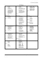
TABLE OF CONTENTS
CHAPTER 1
1-1
INTRODUCTION
1-1
8200 FAMILY OVERVIEW
MODEL NUMBERS
WIDE RANGE OF APPLICATIONS
INPUTS SPECIFICALLY DESIGNED FOR HYDROMET APPLICATIONS
SIMPLE SETUP
EASY WIRING
SEALED UNITS
LARGE SECURE MEMORY
EASILY NETWORKED
1-1
1-2
1-2
1-3
1-3
1-3
1-3
1-3
1-4
CHAPTER 2
2-1
UNPACKING AND INITIALIZATION
2-1
UNPACKING
INITIALIZATION
CONNECTING THE MAIN BATTERY
CONNECTING THE CHARGING VOLTAGE
QUICK TEST
2-1
2-1
2-1
2-3
2-3
CHAPTER 3
3-1
GETTING TO KNOW THE 8200
3-1
8200 FRONT PANEL
THE FRONT PANEL
THE DISPLAY
THE 6-BUTTON KEYPAD
TERMINAL STRIP
RAM CARD SOCKET
RS-232 SERIAL I/O PORT
SDI-12 PORT
GROUND LUG
FRONT PANEL CONTROL OF THE 8200
3-2
3-1
3-1
3-1
3-2
3-2
3-2
3-3
3-3
3-3
i
TURNING THE DISPLAY UNIT ON AND OFF
CHANGING THE DISPLAY BRIGHTNESS
THE 8200 MENU TREE
POSITIONING WITHIN THE MENU TREE
CHANGING VALUES AND EXECUTING FUNCTIONS
PC CONTROL OF THE 8200
STARTING THE PC SOFTWARE
THE 8200 MENU TREE
SELECTING OPTIONS AND CHANGING VALUES
THE SETUP SHEET
EXERCISE
STEPS USING FRONT PANEL
STEPS USING THE TEST SET
OPERATING THE 8200
TURNING ON RECORDING (MENU PATH=RECORDING)
VIEWING LIVE DATA (MENU PATH=VIEW DATA\LIVE READINGS..)
VIEWING LOGGED DATA (MENU PATH=VIEW DATA\NEWEST READINGS..)
SETUPS
3-3
3-3
3-3
3-6
3-7
3-9
3-9
3-10
3-12
3-13
3-17
3-17
3-18
3-19
3-19
3-19
3-20
3-20
CHAPTER 4
4-1
MENU TREE REFERENCE
4-1
8200 MENU REFERENCE
ALARM
APPLICATION MENU (PC ONLY)
DATE
DUMP DATA
EEROM SETUP
EXIT (PC ONLY)
GOES SETUP (GOES MODELS ONLY)
INSPECT SYSTEM
MODEM SETUP (SPEECH/MODEM MODELS ONLY)
PROTOCOL SETUP
RECORDING
SYSTEM SETUP
TIME
UNITID
VIEW DATA
DUMP DATA
DUMP DATA\AUTO DUMP
DUMP DATA\ERASE RAM CARD
DATA\RAM CARD
DUMP DATA\READ CARD SETUP
DUMP DATA\SERIAL PORT
DUMP DATA\START
DUMP DATA\WRITE CARD SETUP
UPLOAD/DOWNLOAD DATA\PROTOCOL (PC ONLY)
ii
4-1
4-2
4-2
4-2
4-3
4-3
4-3
4-3
4-4
4-4
4-4
4-5
4-6
4-6
4-6
4-7
4-8
4-8
4-8
4-9
4-9
4-10
4-11
4-11
4-11
UPLOAD/DOWNLOAD DATA\TRANSFER BASIC PROGRAM (PC ONLY)
UPLOAD/DOWNLOAD DATA\TRANSFER RAW RAM CARD IMAGE (PC ONLY)
UPLOAD/DOWNLOAD DATA\TRANSFER SETUP (PC ONLY)
UPLOAD/DOWNLOAD DATA\VIEW RAM CARD DIRECTORY (PC ONLY)
UPLOAD/DOWNLOAD DATA\YMODEM RAM CARD FILE(S) (PC ONLY)
EEROM SETUP
EEROM SETUP\ANALGDELAY
EEROM SETUP\AUTOKEY
EEROM SETUP\BASICSIZE
EEROM SETUP\COM RATE
EEROM SETUP\DATEFMT
EEROM SETUP\DUMP RATE
EEROM SETUP\ENTER REQD
EEROM SETUP\LOG DUMP
EEROM SETUP\POWERDELAY
EEROM SETUP\PRESSDELAY
EEROM SETUP\RADIO RATE
EEROM SETUP\SDI RATE
EEROM SETUP\SERIAL
EEROM SETUP\TIMEFMT
EEROM SETUP\TIMELIMIT
EEROM SETUP\USER RATE
GOES SETUP (GOES MODELS ONLY)
GOES RADIO SETUP\# DATA/TX ST
GOES RADIO SETUP\CARRIER ST
GOES RADIO SETUP\CHANNEL ST
GOES RADIO SETUP\DATINST
GOES RADIO SETUP\DATTMST
GOES RADIO SETUP\FORMAT ST
GOES RADIO SETUP\INTERNATL
GOES RADIO SETUP\RATE ST
GOES RADIO SETUP\SATID
GOES RADIO SETUP\TIME ST
GOES RADIO SETUP\TXMODE
GOES RADIO SETUP\RANDOM SETUP MENU
GOES RADIO SETUP\RANDOM SETUP MENU\# DATA/TX RR
GOES RADIO SETUP\RANDOM SETUP MENU\#TX/ALARM RR
GOES RADIO SETUP\RANDOM SETUP MENU\ALMINRR
GOES RADIO SETUP\RANDOM SETUP MENU\CHANNEL RR
GOES RADIO SETUP\RANDOM SETUP MENU\DATINRR
GOES RADIO SETUP\RANDOM SETUP MENU\DATTMRR
GOES RADIO SETUP\RANDOM SETUP MENU\RA RATE
GOES RADIO SETUP\RANDOM SETUP MENU\RN RATE
INSPECT SYSTEM
INSPECT SYSTEM\BERT LOS RADIO (FRONT PANEL ONLY)
INSPECT SYSTEM\CLEAR STATUS
INSPECT SYSTEM\DISPLAY STATUS
INSPECT SYSTEM\ENTER SDI-12 CMD
INSPECT SYSTEM\GOES RADIO TEST
INSPECT SYSTEM\M - MONITOR SSP COMMUNICATIONS (PC ONLY)
INSPECT SYSTEM\PERFORM SELFTEST
4-12
4-12
4-13
4-13
4-14
4-15
4-15
4-15
4-16
4-16
4-16
4-16
4-17
4-17
4-17
4-18
4-18
4-18
4-18
4-19
4-20
4-20
4-21
4-21
4-23
4-23
4-23
4-24
4-25
4-25
4-26
4-26
4-26
4-26
4-27
4-27
4-28
4-28
4-28
4-29
4-29
4-29
4-30
4-31
4-31
4-32
4-32
4-35
4-35
4-36
4-37
iii
INSPECT SYSTEM\PRODUCTION TEST
INSPECT SYSTEM\SELECT RADIO (FRONT PANEL ONLY)
INSPECT SYSTEM\T - TALK TO MODEM OR TERMINAL (PC ONLY)
INSPECT SYSTEM\TEST LOS RADIO (FRONT PANEL ONLY)
INSPECT SYSTEM\TRANSMIT STATUS (FRONT PANEL ONLY)
MODEM SETUP (SPEECH/MODEM MODELS ONLY)
MODEM SETUP\#1
MODEM SETUP\ANSWERMODE
MODEM SETUP\DIAL-IN
STANDARD MESSAGES
BUILD YOUR OWN MESSAGE
MODEM SETUP\DIAL-OUT (ENABLE)
MODEM SETUP\DIAL-OUT
MODEM SETUP\NUMBER RINGS
MODEM SETUP\PHONEPASS
MODEM SETUP\REDIAL
PROTOCOL SETUP
PROTOCOL SETUP\# RETRIES
PROTOCOL SETUP\ACK DELAY
PROTOCOL SETUP\CARRIERDLY
PROTOCOL SETUP\HW HANDSHAKE
PROTOCOL SETUP\LONG PACKETS
PROTOCOL SETUP\MASTER
PROTOCOL SETUP\REPLYDELAY
PROTOCOL SETUP\RETRYIN
PROTOCOL SETUP\TA RATE
PROTOCOL SETUP\TN RATE
PROTOCOL SETUP\USE RS-485
SYSTEM SETUP
SYSTEM SETUP\ALARM OPTIONS
SYSTEM SETUP\ALARM OPTIONS\CONTROL
SYSTEM SETUP\ALARM OPTIONS\DEADBND
SYSTEM SETUP\ALARM OPTIONS\ENABLE
SYSTEM SETUP\ALARM OPTIONS\GROUPS
SYSTEM SETUP\ALARM OPTIONS\HIGH ALARM
SYSTEM SETUP\ALARM OPTIONS\HILEV
SYSTEM SETUP\ALARM OPTIONS\LOLEV
SYSTEM SETUP\ALARM OPTIONS\LOW ALARM
SYSTEM SETUP\ALARM OPTIONS\PREFIX/NAME
SYSTEM SETUP\ALARM OPTIONS\ROC ALARM
SYSTEM SETUP\ALARM OPTIONS\ROCLEV
SYSTEM SETUP\ALARM OPTIONS\SUFFIX/UNITS
SYSTEM SETUP\ALARM OPTIONS\TREND
SYSTEM SETUP\CONFIG SENSOR
SYSTEM SETUP\CONFIG SENSORS\AVERAGE
SYSTEM SETUP\CONFIG SENSORS\ELEVATION
SYSTEM SETUP\CONFIG SENSORS\INTERVL
SYSTEM SETUP\CONFIG SENSORS\LOG
SYSTEM SETUP\CONFIG SENSORS\MEASURE
SYSTEM SETUP\CONFIG SENSORS\OFFSET
SYSTEM SETUP\CONFIG SENSORS\RIGHT DIGITS
iv
4-37
4-37
4-37
4-37
4-38
4-39
4-39
4-40
4-41
4-41
4-42
4-50
4-51
4-51
4-51
4-52
4-53
4-53
4-53
4-53
4-54
4-54
4-54
4-54
4-55
4-55
4-55
4-56
4-57
4-57
4-59
4-59
4-59
4-60
4-61
4-62
4-62
4-63
4-63
4-64
4-65
4-65
4-66
4-67
4-68
4-68
4-69
4-69
4-70
4-70
4-70
SYSTEM SETUP\CONFIG SENSORS\SLOPE
SYSTEM SETUP\CONFIG SENSORS\VALUE
SYSTEM SETUP\ENABLE SENSOR
SYSTEM SETUP\MEASMNT SCHEDULE
SYSTEM SETUP\MEASMNT SCHEDULE\#MEASMNT/LOG
SYSTEM SETUP\MEASMNT SCHEDULE\#SAMPLES/SET
SYSTEM SETUP\MEASMNT SCHEDULE\BASINT
SYSTEM SETUP\MEASMNT SCHEDULE\BASTIM
SYSTEM SETUP\MEASMNT SCHEDULE\MEASINT
SYSTEM SETUP\MEASMNT SCHEDULE\MEASTIM
SYSTEM SETUP\MEASMNT SCHEDULE\PWRMODE
SYSTEM SETUP\MEASMNT SCHEDULE\PWRTIM
SYSTEM SETUP\MEASMNT SCHEDULE\SAMPINT
SYSTEM SETUP\MEASMNT SCHEDULE\SAMPTIM
SYSTEM SETUP\BASIC PROGRAM (PC ONLY)
SYSTEM SETUP\CHANGE PASSWORD
SYSTEM SETUP\INIT SETUP
SYSTEM SETUP\ZERO COUNTERS
VIEW DATA
VIEW DATA\ALARM STATUS
VIEW DATA\LIVE READINGS
VIEW DATA\NEWEST READINGS
VIEW DATA\OLDEST READINGS
4-71
4-71
4-72
4-73
4-74
4-74
4-74
4-75
4-75
4-76
4-76
4-77
4-77
4-78
4-78
4-79
4-79
4-79
4-80
4-80
4-80
4-82
4-83
CHAPTER 5
5-1
QUICK SETUP
5-1
REVIEW
BASIC 8200 SETUP
TELEPHONE WITH SPEECH/MODEM
LOS RADIO
SATELLITE UNITS-SELF TIMED
SATELLITE UNITS RANDOM REPORTING
ENTERING THE SETUP
RECORDING: OFF/ON
5-1
5-1
5-2
5-3
5-3
5-4
5-5
5-5
CHAPTER 6
6-1
HOOKING UP SENSORS
6-1
CONCEPTS
ANALOG SENSORS
ANALOG SENSORS 5-8
COUNTER/FREQUENCY SENSORS
SHAFT ENCODER (QUADRATURE) SENSORS
6-1
6-1
6-2
6-3
6-3
v
SDI SENSORS
RS232 SENSORS
CHOOSING SENSORS AND MAKING CONNECTIONS
GROUNDS
SENSOR SETUP EXAMPLES
TIPPING BUCKET
SHAFT ENCODER (QUADRATURE)
WIND SENSOR (WITH AMPLIFIER CIRCUIT)
6-3
6-4
6-4
6-7
6-7
6-8
6-8
6-8
CHAPTER 7
7-1
HOW TO...
7-1
SETUP FOR A SIMPLE STREAM GAUGING STATION
SETUP FOR AVERAGING
SETUP FOR A SIMPLE WEATHER STATION
COMPUTE THE SLOPE AND OFFSET FOR A SENSOR
PRINTING THE SETUP
SCHEDULE DETAILS
SETUP FOR GOES TRANSMISSIONS
SETUP FOR GOES RANDOM TRANSMISSIONS
SETUP FOR LOS RADIO (POLLED)
SETUP FOR TELEPHONE (SPEECH/MODEM)
SETUP FOR TELEPHONE ALARMS
UNDERSTAND ALARMS AND ALERTS
MAKE AN EVENT DRIVEN SYSTEM USING ALARMS
USE AN EXTERNAL MODEM WITH THE 8200
UPLOAD/DOWNLOAD A SETUP
UPLOAD/DOWNLOAD A BASIC PROGRAM
STORE AND FORWARD AND CROSS DEVICE REPEATING SSP MESSAGES
9-PIN INTERFACE CABLE FOR IBM-AT TYPE COMPUTERS
7-1
7-1
7-2
7-3
7-4
7-4
7-5
7-6
7-7
7-7
7-8
7-9
7-10
7-12
7-12
7-13
7-13
7-14
CHAPTER 8
8-1
INSTALLATION
8-1
ENVIRONMENT/ENCLOSURE
POWER BUDGET
CABLING
SURGE AND LIGHTNING PROTECTION
BENCH TESTING
TEST BEFORE YOU LEAVE
GOES ANTENNA POINTING
CHAPTER 9
vi
8-1
8-1
8-3
8-3
8-4
8-5
8-6
9-1
RETREIVING YOUR DATA
INTRODUCTION
LIVE READINGS
LAST MEASURED VALUE
LOGGED DATA
RAM CARDS
USING THE RAM CARDS
TRANSFERRING DATA FROM MEMORY TO A RAM CARD
HOOKING UP THE RAM CARD READER
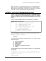
USING THE RAMCARD PROGRAM (FOR 8210 PCMCIA CARDS)
FILE NAMING CONVENTIONS
CONVERTING DATA TO ASCII (SPREADSHEET USABLE) FORM
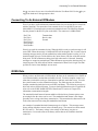
RADIO OPTIONS
ENABLING EXTERNAL RADIO SUPPORT
CONNECTING TO AN EXTERNAL RF MODEM
GOES DATA
9-1
9-1
9-1
9-1
9-1
9-2
9-2
9-3
9-4
9-4
9-4
9-5
9-6
9-6
9-7
9-7
CHAPTER 10
10-1
TINY BASIC
10-1
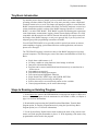
TINY BASIC INTRODUCTION
STEPS TO RUNNING AN EXISTING PROGRAM
CREATING A SIMPLE PROGRAM
STATEMENTS
INITIALIZATION
PERFORMANCE CONSIDERATIONS
EXPRESSIONS
EXAMPLES
INITIALIZING VALUES
WATCHING THE TIME TO MEASURE/LOG
COMPUTE AN AVERAGE, PEAK VALUES, AND ACCUMULATE A SUM
INTERACTING WITH A USER
CREATING STATES TO CONTROL EXECUTION
CUSTOM PHONE HANDLING
CUSTOM GOES FORMATTING WITH TINY BASIC
USING MEM
COMMUNICATING WITH RS-485 SENSORS
TINY BASIC COMMAND SET
TINY BASIC FUNCTION SET
DEVELOPMENT CYCLE
DEBUGGING/TROUBLESHOOTING
ERROR MESSAGE DESCRIPTION
CHAPTER 11
10-1
10-1
10-2
10-3
10-3
10-3
10-4
10-5
10-5
10-5
10-6
10-7
10-7
10-8
10-11
10-13
10-14
10-16
10-22
10-26
10-26
10-26
11-1
vii
MAINTENANCE AND SERVICE
ENCLOSURE
SENSORS
CABLING
BATTERY
ANTENNA AND CABLE
8200 STATUS
DISASSEMBLY/REASSEMBLY 8210
DISASSEMBLY/REASSEMBLY 8200A
FUSES
MULTIPLE MODULE SUPPORT
JUMPERS AND CONNECTORS 8210
JUMPERS 8200A
SATELLITE MODULE JUMPERS
SATELLITE MODULE FAILSAFE RESET
RADIO MODULE JUMPERS
TELEPHONE MODULE JUMPERS
INITIALIZATION AND RESETS
INITIALIZATION
PASSWORD RESET
HARD RESET
11-1
11-1
11-1
11-1
11-1
11-2
11-2
11-3
11-3
11-4
11-5
11-5
11-8
11-9
11-9
11-9
11-10
11-11
11-11
11-11
11-11
CHAPTER 12
12-1
TROUBLESHOOTING
12-1
INTRODUCTION
GENERAL TROUBLESHOOTING PROCEDURES
DISPLAY WILL NOT LIGHT
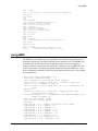
8200 TURNS ON BUT DOES NOT WORK PROPERLY
SENSOR PROBLEMS
SETUP PROBLEMS
LOS RADIO COMMUNICATIONS PROBLEMS
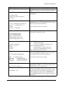
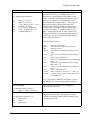
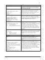
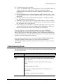
TROUBLESHOOTING GUIDE
SDI-12 INTERFACE STANDARD
GROUNDING
CONNECTOR TYPE
COMMUNICATIONS
SETUP OF SDI SENSORS
ISSUING SDI COMMANDS
USEFUL SDI COMMANDS
POWER CONSUMPTION
Appendix A
Appendix B
Appendix C
Appendix D
viii
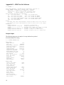
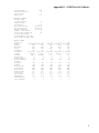
Specifications for the 8200
Blank setup sheets
Assembly drawings
GOES transmission format
12-1
12-1
12-1
12-2
12-2
12-3
12-3
12-5
12-9
12-9
12-9
12-9
12-9
12-9
12-9
12-10
Appendix E
Appendix F
8200 Test Set Software
8210 Sutron Standard Protocol Capabilities
ix
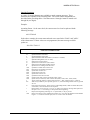
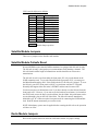
Using This Manual
This manual describes the operation and maintenance of the Sutron 8200 family of data
recorders/transmitters. It is designed to be of use to both beginning and experienced
users. The manual describes the use of all models of the 8200A and 8210 data
recorder/transmitters running software versions 4.0 and above both with and without
telemetry. The manual comes with a diskette that contains programs useful in the setup
and operation of 8200s. Instructions on using the software is provided in Appendix E.
In this manual, 8200 (or 8200s) refers to both the 8200A and 8210. When
necessary to describe the features or differences of a particular model, the
specific model number (8210 or 8200A) is used. Because all models are
described, you should be aware that some information may not apply to
your particular 8200. Do not use this manual as a reference for operating
8200s or 8200As running software versions prior to 4.0.
There are twelve chapters in this manual. These twelve chapters introduce you to the
8200 and present the basics to get you started using the 8200. Chapters 1 through 3
should be read by anyone planning to use the 8200. Chapter 4 contains a detailed
reference of all the 8200 menus and commands. You should not try to read this chapter
start to finish -- it is intended as a reference. The remaining chapters teach you how to
use the 8200 covering topics such as hooking up sensors, common setups, installation,
retrieving data and others. These chapters have many practical examples of using the
8200 in the field. Of particular note is Chapter 7 which contains many examples on how
to use the 8200 in particular situations.
The chapters are presented in the following order:
1.
2.
3.
4.
5.
6.
7.
8.
9.
10.
11.
12.
Introduction
Unpacking and Initialization
Getting to know the 8200A and 8210
Menu Tree Reference
Quick Setup
Hooking up sensors
How To ...
Installation
Retrieving Your Data
Tiny BASIC
Maintenance and Service
Troubleshooting
Specifications for the 8200A and 8210 are contained in Appendix A. Appendix B
contains blank setup sheets. Appendix C contains assembly drawings and bills of
materials for the different model 8200s. Appendix D contains a description of the GOES
transmission format. Appendix E contains information on the programs provided on the
diskette that comes with this manual. These programs are useful in the setup and
operation of 8200s. Appendix F contains information on Sutron Standard Protocol
(SSP), the protocol used by 8200 in most LOS radio and telephone communications.
xi
1
Chapter 1
Introduction
This chapter introduces you to the
Sutron Model 8200 family of data
recorders and transmitters and presents
the features and capabilities that have
made the 8200 the nucleus of data
collection systems throughout the world.
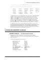
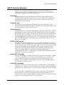
8200 Family Overview
8200 Family Overview
The Sutron 8200 family of data collection products is specifically designed to meet the
wide variety of remote data collection needs of the hydrologic and meteorologic
communities. These needs may range from simple data recording to transmission via
satellite or other telemetry links.
Each 8200 unit has a range of inputs designed to support the most common data
collection applications. These include:
•
•
•
•
•
Water Level
Rainfall
Temperature/pressure
Relative Humidity
Wind speed and direction
The overall 8200 design utilizes CMOS and low-power circuitry to achieve long-life
battery operation and provide a rugged system for unattended field operation in extreme
environments. For even more durability, each 8200 is tested to operate over the -40°C to
+60°C temperature extremes expected in remote environments. Full EMI and transient
protection are built into each input.
The 8200 family is divided into two basic units: the 8200A and the 8210. The 8210 is a
third generation 8200 adding features most asked for by customers. The 8210 datalogger
retains and builds on all the features and programming structure of the 8200A datalogger.
Users can expect the same ease of programming by front panel, flexible setup, and
telemetry options. Enhancements featured in the 8210 include:
•
•
•
•
•
•
•
•
Dual communications now supported in one unit
PCMCIA memory card slot for data or programming storage
True industry standard RS-485 port
20 Digital input/output lines for SCADA or other control applications
Internal auxiliary RS-232 port
Dedicated SDI-12 port with three wire terminal connection
Solar panel battery regulator current increased to 1.25 amps to support larger
solar panels
Dedicated external RS-232 serial port for programming and data retrieval.
Both units (8210 and 8200A) can accommodate optional telemetry modules.
•
•
•
•
•
•
•
telephone modem,
telephone modem with speech synthesis,
GOES radio transmitter,
radio modem with internal radio,
radio modem for external radio
METEOSAT radio transmitter
INSAT radio transmitter.
Introduction
1-1
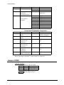
Model Numbers
Model Numbers
The full model number for the 8200 specifies the type of 8200 ordered as well as the
telemetry options selected. The general format of the model number is
82X0-AB14-Y
Y=1, Standard Enclosure -- blue metal box for 8200A
fiberglass box for 8210
Y=2, Modular Mount package
X=0 for 8200A
X=1 for 8210
A=telemetry option 1
B=telemetry option 2 (8210 only)
See Table below
Telemetry Options
0=no telemetry
3=8200-3000 Speech Modem
4= 8200-4000 LOS Modem for external radio
5= 8200-5000 GOES Transmitter
6= 8200-6000 LOS, 4 Watt Radio/Modem
7= 8200-7000 Cellular Modem
The following are some examples of models that can be ordered:
8200-0014-1 8200A, no telemetry
8200-5014-1 8200A with GOES transmitter
8210-5014-1 8210 with GOES transmitter
8210-5014-2 8210 with GOES transmitter, -modular mount
8210-5314-1 8210 with Speech Modem and GOES Transmitter
8210-3614-1 8210 with Speech Modem and LOS, 4 Watt Radio/Modem
Note: the 8200A can have only one telemetry option.
Wide Range of Applications
8200s may be used to collect basic information from sensors to support a variety of
different systems. Typical applications may include:
•
•
•
•
•
•
•
1-2
Flood Warning
Weather Stations
General stage and precipitation networks
Dam safety monitoring
Store-and-forward to Sutron 9000 series SCADA systems
On-site recording of many kinds of digital or analog data
Irrigation control
Inputs Specifically Designed for HYDROMET Applications
Inputs Specifically Designed for HYDROMET Applications
The 8200 family was designed from the ground up for the low cost acquisition of data
from a wide assortment of sensors. By limiting the number of inputs and by specifically
tailoring the design towards measurement of precipitation, wind speed/direction, and
water level, Sutron has provided an economical way to obtain needed information.
Simple Setup
The 8200 is based on a powerful 16-bit microprocessor, allowing users to set up the 8200
in any one of several easy ways:
•
Front Panel -- setup information can be entered using the 6 keys built into the front
panel. The keypad is used to select or modify items in a variety of setup menus.
•
Portable PC -- Those users with access to a portable PC may find it easier to set up
the 8200 through the unit's serial port by using Sutron's TS8210 PC-based software
or standard commercial communications packages (such as PROCOMM).
•
Remote PC -- 8200s with telephone and LOS modems can be set up remotely by
means of a computer terminal or PC.
Easy Wiring
To further ease the process of setup, the 8200s were designed to be easy to hook up in the
field. All connections are made through a terminal strip. For the 8200, the terminal strip
is on the front panel. For the 8210, the terminal strip is either on the side panel or inside
the enclosure depending on the enclosure selected. When all wiring is complete, the
entire terminal strip can be unplugged. This feature greatly simplifies unit swapping
should the occasion arise.
Sealed Units
8200s are designed to operate without additional packaging. They can be placed on a
shelf in a gauge house or weather station with no additional protection. Custom NEMA4 and IP66 housings are available for stand-alone outside applications or where all wiring
must be in conduits. The -2 version of the 8210 is a modular mount version. This
version is designed to easily fit into custom enclosures.
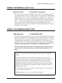
Large Secure Memory
When fully configured, each 8200 system can control up to 384KB of battery backed-up
RAM (Data Storage/ Recording), 256KB of EPROM (Operating System), and 6KB of
EEROM (Setup Information/Passwords & Security). The battery backed-up memory is
used as a "log" for recording data. The standard 128KB memory can hold over 60,000
Introduction
1-3
Easily Networked
readings which translates into nearly two years of data for one sensor recorded every 15
minutes.
The memory system uses Lithium batteries for long shelf life (2 years minimum), and
long safe data storage (1 year minimum).
Easily Networked
The 8200s were designed from the start to work closely with other Sutron data collection
and processing equipment. Telemetry-equipped units communicate in Sutron Standard
Protocol thus allowing them to be used to relay data to Sutron 9000 Remote Telemetry
Units which can then act as repeaters or data processors. The 8200s can also "talk"
directly to Sutron PC or VAX base stations.
1-4
Chapter 2
Unpacking and
Initialization
This chapter provides information to
help you unpack the 8200 and start
using it. You will learn how to hook a
battery to an 8200 and how to run a
quick test to make sure it is operating
properly.
Unpacking
Unpacking
•
Carefully remove the 8200 from the shipping container.
•
Save the container and packing materials as they may be used to transport the
8200 to the site or for shipping the unit back to the factory.
Note: If you want to return a unit to the factory, first fill out the Product
Return Sheet located at the back of this manual and then call the factory (703
406-2800) for an RMA number. This procedure will help us to handle your
equipment in the most efficient manner.
Initialization
All units have been initialized at the factory. Factory initialization consists of:
•
•
•
installing the Lithium Battery jumper to maintain RAM and the internal clock
installing the internal battery (standard and speech/modem models only) and
applying power to the 8200 with the and keys pressed to initiate an
INITIALIZATION.
This last step clears out the databases and autosizes the available memory. For
instructions on doing this initialization yourself, please refer to Chapter 11, page 11-11.
Connecting the Main Battery
The 8200 is designed to run using power from a main battery. Some model 8200s come
with a main 12VDC battery already installed. These models are the basic 8200s (82000014, 8210-0014) and 8200s with only a speech modem installed (8200-3014, 82103014). The battery is a 12V, 6 amp hour, rechargeable battery mounted on the back panel.
All other models require an external battery.
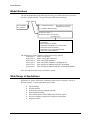
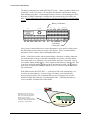
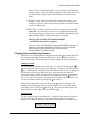
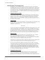
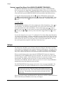
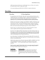
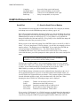
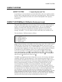
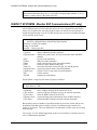
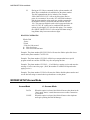
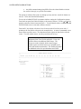
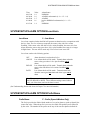
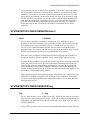
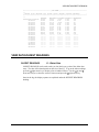
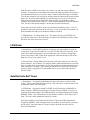
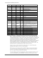
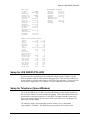
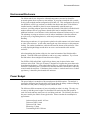
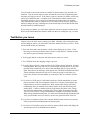
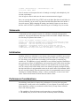
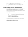
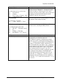
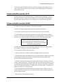
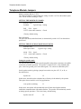
8210 -- The main battery connects to the protection/termination board installed in the
8210. The protection/termination board has several separate connections for the battery
that are connected together internally. One set of connections (J6) accommodates a 2 pin
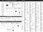
connector and the other set of connections is for use with bare wires. A picture of the
connections is shown on the following page.
If your 8210 comes with an internal battery, the cable with connector is ready to plug into
the J6 receptacle on the protection/termination board. If you have your own battery to
connect to the 8210, use your own cable and connect it to the terminal strip as shown on
the following page. Use 18AWG wire or less to minimize the voltage drop in the cable.
Unpacking and Initialization
2-1
Connecting the Main Battery
The battery connections are marked EXT BATT G and +. Observe polarity with the G as
ground and + as the 12V positive. Be careful to disconnect the cable from the battery
while making connections. Connecting the battery in reverse, will not damage the 8210.
Note that if a GOES Transmitter is installed, the fuse located in the power cable will
blow. Do not connect more than one battery to the 8210 as both batteries will not charge
equally.
Battery Connections
RS-232
-
+
PHONE
G
1
CNT
CHASSIS GND
G
1
ENC1
2
G
1
ENC2
2
G
+
A1
G
+5
+
A2
EXT
BATT
RS-485
-
A
+
G
+
A3
G
+5
SDI
SDI
B
A4
+
D
G
+
G
5
DIGITAL OUTPUT
+
D
G
6
7
8
ANALOG
1
2
3
A
G
+
AUX
SW
PWR
4
5
G
+
SOLAR
PNL IN
Solar Panel
Connections
After you have connected the power source appropriate to your model, you may notice
the 8200 display turn on, then go out after a few minutes. This is a normal function
designed to conserve battery power and lengthen battery life.
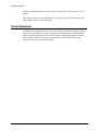
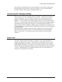
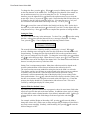
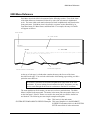
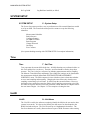
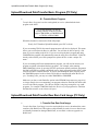
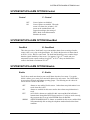
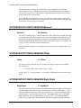
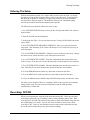
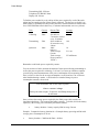
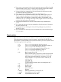
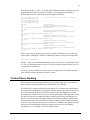
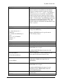
8200A -- If the 8200A comes with an internal battery, the battery is already connected.
To switch the battery ON, press the rubber membrane cover on the rear of the 8200A.
This switch turns on or off battery power to the 8200A each time it is pressed. Press it
once and the display should light up. Press it again, and the battery is disconnected. This
is not to be confused with the button on the front panel of the 8200. The button is
used solely for turning the front panel display on or off. It does not connect/disconnect
the system power.
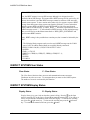
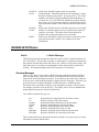
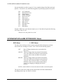
If the 8200A has the label EXT BAT - + on the far left side of the terminal strip, it is
wired for an external battery. Connect a single 12V battery to the terminal strip
observing proper polarity. We recommend that you use an 18 gauge wire or less to
minimize voltage drops that may occur through the cable. Connecting the battery in
reverse will blow an internal fuse on the 8200A.
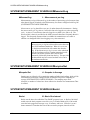
Warning: If you connect the
battery incorrectly, you could
blow one of the internal fuses.
Refer to page 11-4 for
instructions on replacing fuses.
The arrow indicates the location
of the power supply inputs
2-2
EXT BAT
+
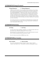
Connecting the Charging Voltage
After you have connected the power source appropriate to your model, you may notice
the 8200 display turn on, then go out after a few minutes. This is a normal function
designed to conserve battery power and lengthen battery life.
Connecting the Charging Voltage
The next step is to connect a charging voltage to the 8200. The 8200 can accomodate a
charging voltage from 13 to 18 volts that is common from a solar panel or DC power
supply. On the 8210, connect the charging voltage to the two pins labeled SOLAR
PANEL G +. On the 8200A, connect the charging voltage to the two pins labeled PWR
IN, G and + on the far right of the terminal strip. This voltage passes through an internal
regulator that keeps the battery fully charged. The internal regulator is limited to 1.25
amp (3/4 amp on 8200A). Without a charging voltage, the 8200 will run using the power
from the main battery. When the battery voltage drops, the 8200 may stop operating until
it is charged again.
Remember that if no internal or external battery is installed, the use of the solar panel
alone will not allow the 8210 to power on. If this application is desired, change the
jumper J7 to position 1-2 on the interconnect board as described in the link table in
Chapter 11.
Quick Test
The 8200 is running whenever the battery is connected. To verify that the 8200 is
running, press on the front panel. The 8200 display should light up with a message
displaying the version of the software. If not, check your connections. If you have an
8200A with internal battery,try pressing the power switch at the back of the enclosure. If
the 8200 still does not light up the display, consult the Troubleshooting Guide in Chapter
12, page 1. Depending on how your particular unit has been set up, the display may
remain on, or turn off after a brief period.
Unpacking and Initialization
2-3
Chapter 3
Getting To Know The
8200
This chapter describes in detail the 8200
front panel (including connections,
controls and displays) and the menus
that you will use to set up and operate
the 8200. Complete information is given
on how to operate the 8200 from the
front panel or a PC.
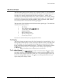
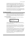
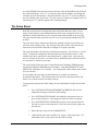
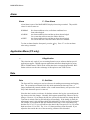
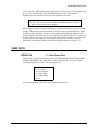
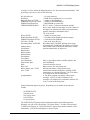
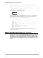
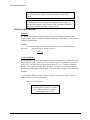
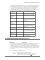
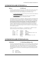
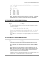
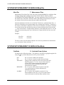
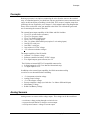
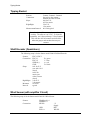
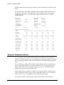
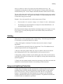
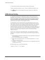
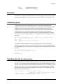
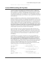
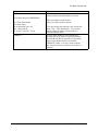
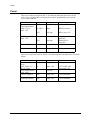
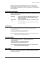
8200 Front Panel
8210 Front Panel (-1 version shown)
Display
SUTRON
RAM Pack Socket
MODEL NO. 8200-0014
SUTRON CORP. STERLING, VA 22170
MADE IN U.S.A.
8200A
DATA RECORDER/TRANSMITTER
RS-232
Serial I
port
DATA CARTRIDGE
SET
Keypad
RS-232
ON
OFF
-
+
EXT BAT G
- +
CNT
GND
Ground Lug
+ G +
G G 1 1 2 2 G +5
G 1
1
G2 1
ENC1
ENC2
1G
G2 +
A1 +5
G
A2
+
G
+ +5 G G+
5
G
+
5
A3
+G
G
+5
SDI-12
I/O port
SW PWR
PWR IN
A4
6
6
ANALOG
7A G
8
+ G
7
8 GA +G
AUX SW PWR
PWR IN
SDI-12
+
+
G
+
RF
OUTPUT
S/N911230
!
Terminal Strips
8200A for external power
(Battery connects to EXT BAT, Solar Panel to PWR IN)
The Front Panel
The Front Panel
The front control panel provides a built-in way to operate the 8200. As you learn how to
enter or select values and move around the menu tree using the control panel keys, use of
the 8200 will be greatly simplified and will soon become intuitive. Another, more
convenient way of setting up the 8200 is to use a test set (which is a PC) running TS8210
(supplied by Sutron) or almost any other communications program. By using it and a PC,
users can view complete menus and data, making it faster to operate the 8200. Both of
these methods will be discussed in the following paragraphs.
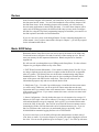
The front panel of the 8200 data recorder is shown on the opposite page. The main items
identified on the front panel are:
•
•
•
•
•
•
•
The display
The 6-button keypad
Terminal Strip (Removable)
RAM Card Socket
RS-232 Serial I/O port
SDI-12 Auxiliary I/O port
Ground Lug (Chassis)
Each item is described briefly in the paragraphs that follow.
The Display
The dark red opaque area at the upper left of the front panel is the system display. It is in
this area that the 8200 displays a variety of messages which are used to set up and test the
unit. The display can also give prompts and messages that are generated by the TINYBASIC application program loaded into memory. The display is ON generally only after
the key is pressed (see below). The brightness of the display can be adjusted by
pressing the key immediately after the display has been turned ON.
The 6-button Keypad
The 6-button keypad (
) is used to control the 8200. The key toggles
the display on and off. The four blue outlined keys marked with black triangles control
the position of the display window in the menu tree. They cause the display to move up,
down, left, and right in the menu tree. The key is used along with the arrow keys to
adjust settings in the display window.
Getting To Know The 8200
3-1
The Front Panel
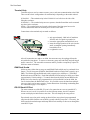
Terminal Strip
Terminal strips are used to connect sensors, power, and some communication to the 8200.
There are three basic configurations for terminal strips depending on the model ordered:
8210-0014-1 --The terminal strisp in the 8210-0014-1 are built in to the side of the
fiberglass enclosure.
8210-0014-2 -- The terminal strips are on a separate, detached board that can be mounted
anywhere in the enclosure.
8200A -- The terminal strips are located at the bottom of the front panel are used to
connect instruments and/or an external power source to the 8200.
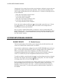
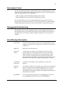
Connections to the terminal strip are made as follows:
• strip approximately 1/8th inch of insulation
from the end of a signal or ground wire
• loosen the appropriate terminal block screw
• insert the stripped portion of the wire into the
small, rectangular opening immediately
beneath the screw
• re-tighten the screw.
After all connections are made to an 8200, the connectors may be unplugged from the
unit with all wiring intact. To remove a connector, grasp each end firmly and pull/wiggle
until it comes free. The removable connectors make it possible to completely replace an
8200 in a matter of minutes.
RAM Card Socket
8200s can store either data or setups on small RAM Cards which may be purchased from
Sutron. The 8210 supports PCMCIA Statid RAM cards (not Flash) with a capacity up to
2MB. The 8200A supports RAM cards with a capacity up to 64K bytes. (The 8200A
RAM cards are not PCMCIA.) Each 8200A RAM Card can hold up to 64k bytes of data
(approximately 32,000 readings). To transfer data from the 8200's internal RAM to the
RAM Card, or to transfer a pre-programmed set-up from a RAM Card to the 8200, the
Card is inserted into the RAM Card socket. It is possible to store the data from multiple
sites on a single card as space permits. Further instructions for loading or unloading data
are contained on page 9-1 in Chapter 9.
RS-232 Serial I/O Port
The most common use of the RS-232 port is for connection to a test set (portable PC).
When a test set is used, it is possible to see the full setup menus since the computer
screen can display an entire menu at one time. This can simplify the setup process.
Experienced users who prefer setting up ahead of time may upload a preprogrammed
setup into the 8200 from the test set thereby greatly reducing setup time. Conversely, the
8200 can also download setups and dump data from its memory to the test set through the
same RS-232 port.
3-2
Front Panel Control of the 8200
This multiple use serial port can also be configured for communication with:
•
•
•
•
an external radio or telephone modem
a Sutron 9000
a printer
RS232/RS485 sensors
SDI-12 Port
The SDI-12 Port provides support for a special serial-digital sensor standard devised by
the U.S. Geological Survey. The SDI-12 standard allows multiple SDI devices to be
connected to an 8200 with each device being able to report up to 9 different parameters.
The 8210 has 2 sets of SDI-12 connections on the terminal strips for connecting multiple
SDI-12 devices. The 8200A has a single DB9 connector for the SDI-12 connection. If
you have more than one SDI device to connect to the 8200A, you may want to use some
kind of external terminal strip instead of connecting all the sensors directly to the 9 pin
connector.
Ground Lug
A ground lug is provided on each 8200 in order to connect the 8200 to an EARTH
ground at the site. On the 8210-0014-1, this ground lug is on the side of the enclosure.
On the 8210-0014-2, the ground lug is on the protection/termination board. On the
8200A, the lug is in the lower left front of the 8200A. Normally, you should run a 16
gauge wire from this lug to the site ground rod. Failure to do so can render the site more
susceptible to damage by lightning.
Front Panel Control of the 8200
Now that you have a working knowledge of the components of the front panel display, it
is time to learn about the 8200's inner workings. As mentioned earlier, the 8200 may be
set up by means of the front panel buttons or a PC equipped with appropriate software.
Even though the 8200 can be set up without using the front panel, it is important to know
how to operate it in this way.
Turning the display unit on and off
The blue-outlined key on the front panel toggles the display on and off. If the display
is turned on and left on with no input/output activity it will turn itself off after 60 seconds
(the time-out period is settable). This time-out feature conserves battery power.
Changing the Display Brightness
The brightness of the display can be changed by pressing when the message Sutron
8210 xxvv is displayed. The best time to do this is immediately after turning the display
ON. Each time is pressed, the brightness will change. There are three brightness
levels to choose from.
The 8200 Menu Tree
The dark red front panel display area can be thought of as being a "window" into the
menu tree. Moving this "window" up and down the menu tree allows the user to see, and
control one level setting at a time. The entire menu tree contains all of the items
available to set up and control the 8200. Not all the items are needed each time the 8200
is set up. In this chapter, we will teach you how to move around through the various
menus using the arrow keys. You do not need to be concerned with the meaning of all
Getting To Know The 8200
3-3
Front Panel Control of the 8200
the items in the menu. The complete description of every menu item is explained in
Chapter 4.
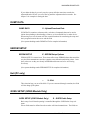
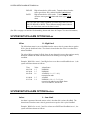
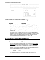
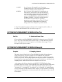
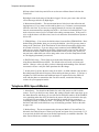
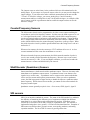
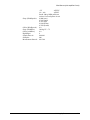
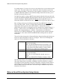
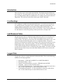
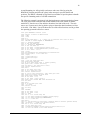
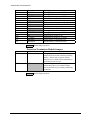
For your convenience, a menu tree for the standard 8200 is illustrated in full view on the
next page. Use it as a reference guide both now and when setting up the 8200. Note that
Menu trees for different model 8200's are similar to the standard version, only with a few
changes appropriate to their different functions (these items appear in bold in the tree).
3-4
Front Panel Control of the 8200
The 8200 Front Panel Menu Tree
Sutron 8210 xxxx
UnitID
Date
Time
Recording
Alarm
VIEW DATA
LIVE READINGS
NEWEST READINGS
OLDEST READINGS
Alarm Status
SYSTEM SETUP
MEASUREMENT SCHEDULE
MeasInt
SampInt
MeasTim
SampTim
PwrTim
#Samples/Set
#Measmnt/Log
BasInt
BasTim
PwrMode
ENABLE SENSORS
Analog1
Analog2
...
CONFIG SENSORS
Measure
Log
Average
Intrvl
Value
Slope
Offset
Elevation
Right Digits
ALARM OPTIONS
Enable
(GOES)
Groups
Control
(MODEM)
Trend
High Alarm
Low Alarm
ROC Alarm
HiLev
LoLev
ROCLev
Deadbnd
Prefix/Name (MODEM)
Suffix/Units (MODEM)
Change Password
Init Setup
Zero Counters
DUMP DATA
Start
Auto Dump
Ram Card
Serial Port
Read Card Setup
Write Card Setup
Erase Ram Card
EEROM SETUP
Serial
User Rate
Radio Rate
Com Rate
Dump Rate
SDI Rate
Enter Reqd
Log Dump
TimeLimit
PowerDelay
PressDelay
AnalgDelay
AutoKey
TimeFmt
DateFmt
BasicSize
PROTOCOL SETUP
Master
CarrierDly
ReplyDelay
Ack Delay
TN Rate
TA Rate
RetryIn
# Retries
Use RS-485
Long Packets
HW Handshake
MODEM SETUP (MODEM)
Dial-Out
AnswerMode
Number Rings
PhonePass
DialIn
DialOut
#1:
#2:
#3:
Redial
GOES Radio Setup (GOES)
Tx Mode
SatID
Internatl
Format ST
Carrier ST
Channel ST
Time ST
Rate ST
#Data/TX ST
DatTmST
DatInST
Channel RR
RN Rate
RA Rate
#TX/Alarm RR
AlmInRR
#Data/TX RR
DatTmRR
DatInRR
INSPECT SYSTEM
Perform Selftest
Display Status
Clear Status
Enter SDI-12 Cmd
Production Test
Select Radio
Test LOS Radio
Bert LOS Radio
Transmit Status
GOES RADIO TEST (GOES)
Send Selftimed
Send Random
Send to Sutron
Getting To Know The 8200
3-5
Front Panel Control of the 8200
Positioning within the menu tree
Positioning within the menu tree is controlled by the 4 keypad keys marked with black
triangles. Pressing the (down arrow) key causes the display window to move one step
down in the menu. Similarly the (up arrow) key causes the display window to move
up within a menu. The (right arrow) key is used to "select" or "move into" a menu
heading. For example, when the display window has been moved down the main menu
until VIEW DATA is shown, pressing will shift the display to show LIVE
READINGS (the first item of the VIEW DATA sub menu). If the menu item has no submenu, pressing will have no affect. The key moves you left or up one menu level
each time it is pressed. If you are in a sub-menu, pressing will return you to the
previous higher menu level. No matter where you are in the menu tree you can return to
the top of the main menu by pressing no more than four times.
Practice moving through the menus using the arrow keys. From the "top" with the
prompt "Sutron 8210 xxvv" press the key until the display shows VIEW DATA. Press
and the display will show LIVE READINGS. Press until the display shows Alarm
Status. Look at the menu tree to see the path you followed by pressing the keys.
Now press
to return to VIEW DATA.
Press until INSPECT SYSTEM is displayed. Press
Perform Selftest.
and the display will show
Press again and notice that the display does not change. This is because there is no
sub-menu for Perform Selftest. As a general rule, when the display is in all capital
letters, you can press to bring up a sub-menu. When the display is in a mixture of
upper and lower case letters, there is no sub-menu.
Press
as many times as it takes to get back to the "top" of the menu tree.
Special Tip: If you hold one of the arrows down for more than a half
second, it will automatically repeat.
Now that you can navigate through the menus, let us introduce a few terms or
conventions we have adopted to help describe the 8200 menus.
MAIN MENU -- We will use the term main menu to describe all those items that
appear by pressing only the down arrow from the top of the tree. These
items are UnitID, Date, Time, Recording, Alarm status, VIEW DATA,
SYSTEM SETUP and so forth. (When using a PC, all these items appear in
a single menu which makes the concept of a MAIN MENU more clear.
MENU, SUBMENU -- There are also other menus and submenus in the 8200.
Like the main menu, they contain all the items that appear by pressing only
the down arrow. The SYSTEM SETUP menu has the items
MEASUREMENT SCHEDULE, ENABLE SENSORS, CONFIG
SENSORS, ALARM OPTIONS, Change Password and SETUP. As a
convention, any item that is in all capital letters is another menu.
FIELD -- We will use the term field to describe any item in the menus that
accepts a value. You will always see the value displayed next to the name of
3-6
Front Panel Control of the 8200
the field. Time is a field (which holds the value of the time) as is Recording
and many others. You set the 8200 by changing the values of the fields. You
will note that the fields have names with both upper case and lower case
letters.
FUNCTION -- Some items in a menu look like fields but do not have a value
displayed. These are functions, that cause the 8200 to do something. An
example of a function is Init Setup that causes the 8200 to clear and initialize
its setup to default values.
MENU PATH -- A final convention that we have developed is what we call the
menu path. The menu path is a concise way of explaining the menus and
sub menus used to go to a specific item. You read the menu path from left to
right and MAIN MENU is implied in the path. For example
MENU PATH=SYSTEM SETUP\MEASUREMENT
SCHEDULE\Switched Power Options.
tells you to select SYSTEM SETUP from the MAIN MENU (main menu is
implied) and then MEASUREMENT SCHEDULE (from the SYSTEM
SETUP menu) and then Switched Power Options (from the
MEASUREMENT SCHEDULE menu).
Changing Values and Executing Functions
Functions are executed and fields are changed by means of the key and the arrow keys.
The following paragraphs illustrate how these keys are used to set the Unit ID, Date,
Time, and Recording. Similar keystrokes are used to change any field in any menu tree.
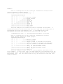
Setting the Unit ID
The Unit ID is the second entry in the main menu. To select the Unit ID press the key
once after the Sutron 8210 vvxx message is displayed. To change the Unit ID, press the
key. A flashing cursor will appear at the first character of the Unit ID. To change the
first character, press the up or down arrow keys. Each depression will cause the
displayed character to change. Numbers from 1 through 0 and letters from A through Z
are available. When you have the desired selection displayed, press the right arrow
key to move to the next character. Repeat this process until the Unit ID is correct. (You
can move backwards in the ID by pressing the left arrow key.
When you have entered the Unit ID you desire, press to make it permanent. The
flashing cursor will disappear and your selection will be saved. If you wish to cancel
your change of the Unit ID, press instead of . This causes the 8200 to ignore your
selection, and restore the original value for the Unit ID.
Setting the Date
The Date is the third entry in the main menu. To select the Date, press the down arrow
key once after setting the Unit ID, or twice after the Sutron 8210 xxvv message is
displayed. The date will normally be displayed in the Month-Day-Year format such as:
Date: 05/21/1992
Getting To Know The 8200
3-7
Front Panel Control of the 8200
To change the Date, press the key. When is pressed, a flashing cursor will appear
on the first character of the month field. To change the first character of the month, use
the up and down arrow keys, just as in setting the Unit ID. To change the second
character, press the right arrow key and then use the up/down arrow keys to select the
key again. Notice that the 8200 will not allow you
proper digit. Now, try to press the
to advance to the day value by using the arrow key. You must first save or "set" your
new selection of the month before advancing to the day. To do so, press .
When is pressed, the cursor will shift to the first digit of the day field. Set the day in
the same way as the month and press to shift to the year field. Set the digits in the year
using the arrow keys. Press a final time to complete the operation of setting the Date.
Setting the Time
The Time is the fourth entry in the main menu. To select Time, press once after setting
the Date, or three times after the Sutron 8210 xxvv message is displayed. To change
Time, press the key. Time is displayed in the following 24-hour format:
Time: 17:55:01
The seconds field will be advancing steadily as the display is viewed. When is
pressed, a flashing cursor will appear at the first digit of the hour field and the time will
stop advancing. To change the first digit in the hour field, use the up and down arrow
and then
keys, just as in setting the Unit ID or date. To change the second digit, press
use / to select the proper digit. When the hour is correct, press to "lock" that field
and shift the cursor to the first digit of the minute field. The minute and second fields are
then set in exactly the same way as the hour field.
Setting Time is an important operation. Many data collection activities depend on the
accurate synchronization of times between numerous data collection devices.
The correct and most accurate method for setting the time in the 8200 is to select the
Time display, and key in a full time (up to the seconds value) that is one or two minutes
in advance of the current time. Since the 8200 senses that an operation is being
performed, it will not automatically shut off the display while you are waiting for the
time synchronization. Press only when the time on the display coincides exactly with
the time on an accurate source (Digital wrist watch, radio time signal, etc.). From that
point on, the display should be in synchronization with reference time. This can be
verified by watching the display for a short period.
Options With Pre-Defined Values
Up to this point, you have learned how to program in values for menu items (fields) that
require user specific data such as the time and date. In addition to these types of settings
are fields which contain a limited number of pre-defined, unalterable values. In this type
of menu field, the value of the field changes to the next legal value each time is
pressed.
For example, with the Display at Recording: OFF, pressing will cause the 8200 to
change the value to ON. (Some error or status messages may be displayed if the 8200 is
not ready to start recording). Similarly, with Recording: ON, pressing will cause the
8200 to change it to OFF.
3-8
PC Control of the 8200
At times there are more options than just ON and OFF. For example, the Serial field in
the EEROM SETUP menu has the value options: USER, SENSOR, LOGGER,
PROTOCOL, RADIO, EXTMODEM, MODEM. (values in all CAPS do not contain
sub-menus). Each time is pressed, the display scrolls to the next possible value for the
field, eventually moving back to the beginning of the list. For the EEROM SETUP field
of User Rate, pressing will cause the display to cycle through all the available baud
rate values for the serial port 110, 300, 600, 1200, 2400, 4800, 9600 and so forth. To
lock in a value, simply press the left arrow button to exit the option.
When working with fields with pre-defined values, the 8200 remembers only the value
that was displayed when you exited the field. So, if you press and change the EEROM
SETUP, Serial: option from USER to PROTOCOL and then press (or let the display
time-out), the next time you view Serial: it will be set to PROTOCOL.
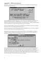
PC Control of the 8200
Those users wishing to take advantage of the 8200's powerful interfacing capabilities
may choose to set up their unit with a PC instead of with the front control panel.
Although using a PC to set up the 8200 requires a different method of value setting, the
process is much simpler and less time consuming. The first step is to hook up the 8200
and the computer together and get the communications software up and running.
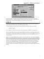
Starting the PC Software
Any PC can be used as a test set as long as it has a serial port and a communications
program such as the Sutron designed TS8210.
Note: if using a commercial
communications program, set it for 9600
baud, 8 bits, no parity,
1 stop bit.
To link the two machines together, connect a standard 9 pin straight cable from the
COM1 port to the 8200 Serial RS-232 port. Should you need to make a cable yourself,
refer to the information on page 7-13.
Start the TS8210 program by typing TS8210 at the C:\ prompt of your computer or
whatever subdirectory the TS8210 program happens to be in. The 8200 should display
the main menu onto the PC screen. If you do not see the main menu when TS8210 is
started, or if the display blanks, press the F10 key. This sends a signal to the 8200 to
wake up and display the menu again.
If the 8200 still does not display the main menu, you must use the front panel of the 8200
to verify that the EEROM setup is configured for the Serial port. To do so, press to
until EEROM SETUP is displayed. Press and the
turn on the display and then use
display should show Serial: USER. If it does not, press repeatedly until the USER
value appears. Then use to display the User rate (Baud operating speed). It should
show the baud rate as 9600 baud. If it does not, press until the baud rate is 9600.
Press F10 on the PC to try again. If you are still having difficulties, consult the
Troubleshooting chapter (10) for help.
Getting To Know The 8200
3-9
PC Control of the 8200
The 8200 Menu Tree
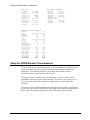
Since the PC screen is obviously much larger than the small 8200 display, it is able to
give a full view of the menus. A complete list of the 8200 PC menus is shown on the
following pages. Note that PC menus are able to show all the items of a menu grouped
together. Separate menus are given for each of the model 8200s; however, all 8200s
share most of the same menus and fields.
If you will remember, when using the front panel display to set up the 8200 you were
required to push the directional arrows to move around the menu tree. When using a PC,
the letter in front of each option indicates the key that must be pressed in order to select
the item and move around the menu. For example, pressing V will bring up the VIEW
DATA menu. Pressing A from within this submenu will bring up the Alarm Status
display. The [ESC] key on the PC is used to return to the previous menu.
Practice using the menus by selecting some of the keys such as E to select EEROM
Setup, or S for System Setup. Press [ESC] to return to the main menu. Note that when
you press R from the main menu, a submenu does not appear. Instead, the 8200 will
change or scroll through the state of Recording options; ON and OFF. This is an
example of a field that you can set; it is not a menu that can be displayed.
3-10
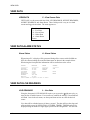
PC Control of the 8200
PC Menus
MAIN MENU
N - Unit Name
D - Set Date
T - Set Time
R - Recording Status
C - Clear Alarm
V - View Sensor Data
S - System Setup Options
U - Upload/Download Data
E - EEROM Setup Options
P - Protocol Setup Options
M - Modem Setup Options
G - GOES Radio Setup
I - Inspect System
A - Application Menu
X - Exit
Choose:
Upload/Download Data Menu
D - Start Date
P - Protocol
A - Auto Dump
C - Send to Ram Card
S - Send to Serial Port or Modem
R - Read Setup from Ram Carrd
W - Write Setup to Ram Carrd
T - Transfer Setup
B - Transfer Basic Program
Y - Ymodem Ram Card File(s)
I - Transfer Raw Ram Card Image
V - View Ram Card Directory
E - Erase Ram Card
Choose:
GOES Radio Random Setup Menu
1 - Channel
(RR)
2 - TX Normal Rate (RR)
3 - TX Alarm Rate (RR)
4 - # TX/Alarm
(RR)
5 - Alarm Interval (RR)
6 - # Data Items/TX (RR)
7 - Data Time
(RR)
8 - Data Interval (RR)
Choose:
View Sensor Data Menu
L - Live Data
N - Newest Data
O - Oldest Data
A - Alarm Status
Choose:
EEROM Setup Menu
M - Serial Port Mode
U - User Baud Rate
R - Radio (LOS) Baud Rate
C - Com Baud Rate
T - Transfer Baud Rate
S - SDI-12 Baud Rate
E - Enter Key Required
D - Log Dump Mode
L - User Time Limit (sec)
O - Power On Delay (10*ms)
P - Pressure Delay (10*ms)
A - Analog Delay (10*ms)
K - Auto Startup Keys
1 - Time Format
2 - Date Format
B - Basic Prog Size (KB)
Choose:
Protocol Setup Menu
M - Master Name
C - Carrier Delay (.1s)
R - Reply Delay (.1s)
A - Ack Delay (.1s)
1 - TX Normal Rate
2 - TX Alarm Rate
3 - Retry Interval
N - Number of Retries
U - Use RS-485 w/SDI-12
L - Long SSP Packets
H - H/W Handshake on COM
Choose:
Alarm Options
E - Enable
G - Groups
C - Control
1 - High Alarm
2 - Low Alarm
3 - ROC Alarm
Alarm Limits
H - High Limit
L - Low Limit
R - ROC Level
B - Deadband
Alarm Phrases
P - Prefix (Name)
S - Suffix (Units)
System Setup Menu
M - Measurement Schedules
E - Enable Sensors
C - Configure Sensors
A - Alarm Options
B - Basic Program
P - Change Password
I - Init Setup
Z - Zero Counters
Choose:
Measurement Schedules
M - Measurement Interval
I - Sampling Interval
T - Measurement Time
S - Sampling Time
P - Switched Power Time
A - Samples to Average
L - Measurements per Log
B - Basic Run Interval
R - Basic Run Time
O - Switched Power Options
Choose:
Configuration
M - Measure
L - Log
A - Average
I - Interval
Calibration
V - Value
S - Slope
O - Offset
E - Elevation
R - RightDigits
Modem Setup Menu
D - Dial-Out Enable
A - Answer Mode
N - Number of Rings
P - Phone Password
I - Dial-In Message
O - Dial-Out Message
1 - Phone #1
2 - Phone #2
3 - Phone #3
R - Redial Delay
Choose:
Inspect System and Test
S - Perform Selftest
D - Display Status
C - Clear Status
E - Enter SDI-12 Commands
T - Talk to Modem or Terminal
G - GOES Radio Test
M - Monitor SSP Communications
P - Production Test
Choose:
FRONTPANEL ONLY:
Test LOS Radio
Transmit Status
GOES Radio Setup Menu
T - Transmit Mode
S - Satellite ID
I - International
F - Format
(ST)
C - Carrier
(ST)
1 - Channel
(ST)
2 - TX Time
(ST)
3 - TX Rate
(ST)
4 - # Data Items/TX (ST)
5 - Data Time
(ST)
6 - Data Interval (ST)
R - Random Setup Menu
Choose:
Getting To Know The 8200
3-11
PC Control of the 8200
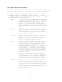
Selecting options and changing values
To change the value for a field, press the key identified for the field. If the field has
predefined options, the value will change to one of the predefined values. If the field has
a user entered value, the cursor will move to the place where the value is displayed and
let you key in the value. The following paragraphs illustrate how the keys are used to set
the Unit ID, Date, and Time. Similar keystrokes are used to change any programmable
item in any menu tree.
Setting the Unit Name (UnitID)
The Unit Name (UnitID) is the second entry in the main menu. The letter N is used to
select this item to change it. Press N and the cursor will jump to the Unit Name that is
displayed. Type in a new unit ID or press [BACKSPACE] and edit the existing ID.
When the value is correct, press [ENTER]. You may press [ESC] at any time to cancel
the change to the Unit Name.
Setting the Date
The Date is the third entry in the main menu. To select the Date, press "D" and the cursor
will jump to the first field in the date. The date will normally be displayed in
MM/DD/YY format such as:
05/21/1992
Type in a new month or press [BACKSPACE] and edit the existing month. Once you are
satisfied with the change, press [ENTER] to "lock" in the new monthly value and go to
the next field which is the day. Use the same steps to change the day and year. Pressing
[ENTER] while in the year field will cause the 8200 to accept the entire new date. If
[ESC] is pressed at any time, the cursor returns to the menu without changing the date.
Setting the Time
The Time is the fourth entry in the main menu. To select the Time, press "T" and the
cursor will jump to the hours field. Type in a value for the hours or press
[BACKSPACE] and edit the existing hours value. Press [ENTER] to go to the minutes
section. Use the same steps to change the minutes and seconds.
Setting the time is an important operation. Many data collection activities depend on the
accurate synchronization of times between numerous data collection devices.
The correct and most accurate method for setting the time in the 8200 is to select the
Time display, and key in a full time (up to the seconds value) that is one or two minutes
in advance of the current time. After keying in the correct value for the last field
(seconds) wait to press [ENTER] only when the time on the display coincides exactly
with the time on an accurate source (Digital wrist watch, radio time signal, etc.).From
that point on the display should be in synchronization with the reference time. This can
be verified by watching the display for a few seconds.
Changing Pre-Defined Values
If an item has a pre-set value, the 8200 will change the value each time the item is
selected. For example, go to the main menu and press "R". If the current status is
Recording: OFF, the 8200 will try to set it to next available option of ON and vice versa.
3-12
The Setup Sheet
Go to the EEROM Setup Options menu and note the value for Dump Rate (also known as
the Transfer Baud rate). Press "T" several times and watch the display cycle though the
available values for the baud rate. Note that each time you press "T" you are scrolling to
the next available value for the item. The only way to set it back to its original value is to
repeatedly press "T" until the original value is displayed again.
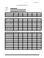
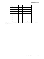
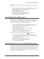
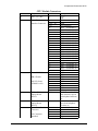
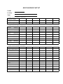
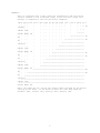
The Setup Sheet
Now that you know how to navigate the menus of the 8200 and enter values, you are
ready to learn about the actual method behind an 8200 setup. Perhaps the best way to
familiarize yourself with this step is by using the setup sheet included on the next page.
The setup sheet has been prepared for you as a way of specifying the intended setup for
an 8200.
The setup sheet closely matches the 8200 menus, making it simple to use the sheet as a
reference when entering a setup. The sheet provides spaces for the values that may be
entered into various fields in the 8200 to configure it for proper operation.
The setup information is divided into two different setup sheets. The first sheet -- Sensor
Setup -- contains the configuration data and alarm data for all enabled sensors. Each
column in this sheet contains the setup information for a single sensor. Since there are
only six columns on this sheet, you will need to use additional copies of the sheet if there
are more than six sensors in your setup.
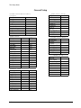
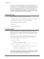
The second sheet defines the values for the Measurement Schedules, EEROM settings,
and optional GOES and MODEM setup information. Note that EEROM SETUP and
PROTOCOL SETUP have two columns -- one listing default values and the other a blank
for your selection.
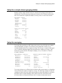
As an example, the setup sheet has been filled out for a simple site measuring
precipitation and battery. This setup measures data from the precipitation sensor and
battery every minute and stores the data in the log.
To program the setup into the 8200, simply enter the information from the sheet into the
8200:
•
Go to SYSTEM SETUP\MEASUREMENT SCHEDULE and enter the
information from page 2 under the same heading
•
Go to SYSTEM SETUP\ENABLE and enable the appropriate sensors as
given on the setup sheet. Also change the name for sensors as required.
•
Go to SYSTEM SETUP\CONFIGURE and enter values into the fields for
the sensor as given on the setup sheet. Finish one sensor before going on to
the next one.
•
Repeat the above steps for the ALARM SETUP.
•
Check and enter the values from the rest of page 2 of the setup sheet. The
information can be easily entered into the 8200 by noting:
Getting To Know The 8200
3-13
The Setup Sheet
The sheets have the values grouped so that it is simple to read the data off the sheet and
enter it into the 8200.
3-14
The Setup Sheet
8200 SENSOR SETUP
UnitID
Location
Name
SYSTEM SETUP\ENABLE SENSORS
8200 Sensor Type
Counter
Battery
Enable
ON/OFF
ON
ON
New Name (optional)
SYSTEM SETUP\CONFIG SENSORS
Measure
ON/OFF ON
ON
Log
ON/OFF
ON
ON
Average
ON/OFF
OFF
OFF
Intrval
00:00:00
Value (Forced)
0000.000
Slope
0000.000
0.01
1.0
Offset
0000.000
0.0
0.0
Elevation
0000.000
2
1
RightDigits
0-3
SYSTEM SETUP\ALARM OPTIONS
Enable
Groups (GOES ONLY)
Control
Trend (MODEM ONLY)
High Alarm
Low Alarm
ROC Alarm
HiLev
LoLev
ROCLev
DeadBnd
Prefix (MODEM ONLY)
Suffix (MODEM ONLY)
Getting To Know The 8200
3-15
The Setup Sheet
General Setup
SYSTEM SETUP\Measurement
Schedule
MeasInt
00:15:00
SampInt
MeasTim
SampTim
PwrTim
#Samples/Set
#Measmnt/Log
BasInt
BasTim
PwrMode
EEROM SETUP
Serial
User Rate
Radio Rate
Com Rate
Dump Rate
SDI Rate
Enter Reqd
Log Dump
TimeLimit
PowerDelay
PressDelay
AnalgDelay
AutoKey
TimeFmt
DateFmt
BasicSize
USER
9600
1200
1200
9600
1200
OFF
ALLBIN
60
1
5
5
(blank)
NORMAL
MDY
1
PROTOCOL SETUP
Master
CarrierDly
ReplyDelay
ACK Delay
TN Rate
TA Rate
RetryIn
# Retries
Use RS-485
Long Packets
HW Handshake
(blank)
7
0
100
00:00:00
00:10:00
00:01:00
3
OFF
ON
OFF
3-16
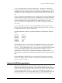
GOES Radio Setup
Tx Mode
SatID
Internatl
Format ST
Carrier ST
Channel ST
Time ST
Rate ST
#Data/TX ST
DatTmST
DatInST
Random Setup Menu
Channel RR
RN Rate
RA Rate
#TX/Alarm RR
AlmInRR
#Data/TX RR
DatTmRR
DatInRR
MODEM Setup
Dial-Out
AnswerMode
Number Rings
PhonePass
DialIn
DialOut
#1:
#2:
#3:
Redial
Exercise
Exercise
Now, enter the information from the sample sheet into the 8200. The main steps you should
follow to set up the 8200 are:
•
•
•
Enter Measurement Schedule
Enable Sensors
Configure Sensors.
You may use either the front panel or test set. Try it yourself. If you need help refer to the
guide that follows.
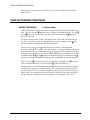
Steps using Front Panel
Step 1, Moving to SYSTEM SETUP (Menu Path=SYSTEM SETUP)
If you have not already done so, turn on the 8200 display by pressing . Sutron 8210 xxvv
should be displayed. If the unit is already on and something other than Sutron 8210 xxvv is
displayed, press until the message is displayed. This is the top of the menu tree.
To move to the SYSTEM SETUP item in the main menu, use
. Use
if you go too far.
Step 2, Setting the measurement schedule (Menu Path=SYSTEM
SETUP\MEASUREMENT SCHEDULE)
With SYSTEM SETUP in the display window, press to move to the MEASMNT
SCHEDULE sub-menu. Press again to move into the MEASMNT SCHEDULE subkey and use the
menu. The display window will show MeasInt xx:xx:xx. Press the
procedures described under setting the Time and Date to select the desired interval between
measurements. For this example, set the MeasInt to 00:01:00 -one minute. The fields in
MeasInt are hours, minutes, and seconds.
MeasInt is the only setting required in the MEASUREMENT SCHEDULE for this simple
application. After setting the MeasInt you may use and to see some of the other times
which should all be set to 00:00:00.
Step 3, Enabling sensors (Menu Path=SYSTEM SETUP\ENABLE SENSORS)
Press to return you to display MEASMNT SCHEDULE. Press
to move to the
to move into the sub-menu. The display will read
ENABLE SENSORS sub-menu. Press
Analog1 xx, where xx is ON or OFF.
The ENABLE SENSORS sub-menu contains a Master Sensor List of all the ways the 8200
inputs can be configured. Press until Counter is displayed. Press to toggle the Counter
until Battery is displayed. Toggle it ON also.
ON. Continue pressing
Step 4, Configuring sensor inputs (Menu Path=SYSTEM SETUP\CONFIG SENSORS)
Pressing to return to the main menu. The display will be at the ENABLE SENSORS
to move into the
item. Press to move to the CONFIG SENSORS sub-menu. Press
sub-menu. The display should show Counter _____. If it shows another sensor, press
until COUNTER is displayed.
Getting To Know The 8200
3-17
Exercise
Press to enter the configuration submenu for the COUNTER. The display will show
MEASURE xx, where xx is ON or OFF. Press to toggle MEASURE ON.
to move down the COUNTER submenu. The display will show Log xx, where xx
Press
to toggle logging (recording in memory) ON. If Log is OFF you
is ON or OFF. Press
will get no recorded data for a sensor, regardless of other settings.
Press and the display will return to the sensor list and will show COUNTER MeLg. The
Me indicates that Measure is On and Lg indicates that LOG is ON.
Press to select the BATTERY submenu. The display will show BATTERY. Press
enter the submenu and use the same steps as described for the COUNTER to turn on
(missing text -- AG 3/16/93)
Measurement and Logging for the BATTERY. Press
should now show BATTERY MeLg__.
to
Steps using the Test Set
Step 1, Moving to SYSTEM SETUP (Menu Path=SYSTEM SETUP)
From the main menu, press "S" to select SYSTEM SETUP (You may also
need to press [ENTER] to get the 8200 to accept your menu selection.)
Step 2, Setting the measurement schedule (Menu Path=SYSTEM SETUP\measurement
schedule )
With SYSTEM SETUP Menu displayed, press "M" to select the Measurement Schedule.
Press "M" to select the Measurement Interval and then press 0 [ENTER] 1 [ENTER] 0
[ENTER] to set the value 00:01:00 into the Interval.
There are no other values to change in the Measurement Schedule. Press [ESC] to return to
the System Setup Menu.
Step 3, Enabling Sensors (Menu Path=SYSTEM SETUP\ENABLE SENSORS )
Press "E" to select ENABLE SENSORS. The display will show a complete list of all the
sensors supported by the 8200. Note the cursor pointing to Analog1. Use the keyboard
arrow keys to move the cursor to point to Counter. Press [ENTER] and note the "*"
indicating that Counter has been enabled.
Use the keyboard arrow keys to move the cursor to Battery and again press [ENTER]. To
disable a sensor, move the cursor to the name with a "*" in front of it and press [ENTER].
The sensor will be disabled and the "*" removed.
Press [ESC] to return to the System Setup Menu.
Step 4, Configuring sensor inputs (Menu Path=SYSTEM SETUP\CONFIG SENSORS )
Press "C" to select Configure Sensors. The display will show a list of enabled sensors on the
left with a cursor pointing to the top value. The data on the right will be from the sensor the
cursor is pointing to. If the cursor is not at Counter use the arrow keys to move it.
Press "M" to toggle Measure ON/OFF. If it shows OFF, press it again until it is ON.
Press "L" to toggle LOG ON/OFF. If it shows OFF press it again until it is ON.
3-18
Operating the 8200
Make sure the other values for COUNTER are correct and change them if necessary.
When you are finished configuring Counter, press the arrow key to move the cursor to
BATTERY. Note that the values on the right will change as BATTERY is selected.
Following the same procedure as above, set Measure ON and Log ON and make sure all
other values are correct.
Press [ESC] to return to the setup menu. Press [ESC] again to return to the main menu.
Operating the 8200
Turning on Recording (Menu Path=Recording)
With the 8200 set up, you are ready to turn on Recording. With Recording OFF, the 8200
will not automatically measure data or transmit it.
To turn ON Recording from the front panel, use the arrows to select Recording and press
The status of Recording should change to ON.
.
Note: the 8200 will prompt OK to erase log? if you have made any changes
to the setup that affect the log size (such as enable/disable logging of sensors
or change MeasInt. If you see this message, press to proceed. Pressing
any other key aborts the change to Recording ON.
To turn ON Recording from a test set, press "R" in the main menu. Again, note the change
of the status to ON. If you see the OK to erase log, you will need to press Y to proceed.
Pressing any other key aborts the change to Recording ON.
Viewing Live Data (Menu Path=VIEW DATA\LIVE READINGS..)
To view data from the front panel, press to display VIEW DATA followed by . The
display will show LIVE READINGS. Press again to select the live readings and the live
data for COUNTER will be displayed. If some sensor other than COUNTER is displayed
to view the BATTERY
press the down arrow until COUNTER is displayed. Press
voltage. Use and to display the desired values. To exit the display, press .
To view data from the test set, press "V" to select View Data followed by "L" for live
readings. Then select sensors from the list by moving the cursor to the desired sensors and
pressing [ENTER]. Selected sensors will show the "*". Note the menu at the top of the
screen describes the keys the 8200 recognizes while in this menu. Press "V" to activate the
viewing of data. Press [ENTER] to select the default update interval of 1 second. To exit
the display, press [ESC].
To watch the live display of the COUNTER change, connect one wire to CNT-G and the
other to CNT-1 and touch the ends of the two wires together. The value for counter will go
up each time the wires are touched together. Note that the value may jump up by increments
greater than one. This is because the "debounce" circuitry is designed for magnetic reed
switches or mercury switches. Brushing wires together creates a very noisy signal which the
circuitry cannot handle properly.
Getting To Know The 8200
3-19
Setups
Viewing Logged Data (Menu Path=VIEW DATA\NEWEST READINGS..)
The NEWEST READINGS and OLDEST READINGS Sub-menus of VIEW SENSOR
DATA are used to view logged data. Selecting either of these will let you view data in the
log. As implied in the selection, NEWEST READINGS will start the display with the most
recent data in the log and OLDEST READINGS will start with the oldest data in the log.
To view data using the front panel, first use to display VIEW DATA from the menu.
Press to display LIVE READINGS and press to display NEWEST READINGS. Press
to display COUNTER and again to see the most recent data. The display format will
appear as:
135 1258 +00024
to
The left number in the display (135 in the example) is the Julian Calendar day. Press
see the full date. (It will only be displayed briefly.) The second value in the display is the
time, and the third value is the recorded data. To move back in time, press . To move
forward in time, press . To move back to the sensor list for NEWEST READINGS, press
. You may use and to select any other sensor that is logged followed by to view
its data.
To view data using the test set, press "V" to display the View Sensor Data menu followed by
"N" for the newest readings. A display of the most recent log entries will be displayed along
with a menu across the top of the screen. If all the sensors do not fit on the screen, you will
need to use the "R" and "L" keys or the arrow keys to scroll to the right and left. You may
also scroll up and down using the U and D keys or the arrow keys.
Setups
The 8200 setup is in RAM, a type of memory that can be changed. This makes it possible
for the 8200 to be configured by the customer to function a particular way. The setup can be
quite short or long depending on its complexity. For improved reliability, the 8200 keeps a
copy of the setup in a special area of write-protected and checked memory called EEROM.
When you make changes to the setup using the SYSTEM SETUP menu, the changes are
automatically saved to EEROM when you leave the menu. The software only saves values
for sensors that are enabled. Alarm information will also be saved only for sensors that are
alarm enabled. The 8200 has room to store up to 70 sensors and their related alarm
information in the EEROM. When the 8200 is powered on or reset, the setup in EEROM is
automatically restored to RAM and used by the 8200.
The SYSTEM SETUP\Init Setup option can be used to clear out a setup from RAM. The
cleared setup will also be copied to EEROM when you exit the SYSTEM SETUP menu.
Note: previous versions of the 8200 software had separate functions to
save and restore the setup. This caused confusion and inconsistencencies
in the setup. This automatic saving and restoring will make the 8200
easier to use.
Other setup options found in the EEROM SETUP, PROTOCOL SETUP, GOES SETUP and
others saved directly to EEROM as soon as they are changed.
3-20
Setups
The 8200 also has the capability to transfer the setup to and from a RAM Card that can be
inserted into the front panel, and to and from a test set using the Xmodem or Ymodem
protocols. Refer to Page 9-2 for details.
Getting To Know The 8200
3-21
Chapter 4
Menu Tree Reference
This chapter describes in detail all the
items that make up the 8200 setup. The
chapter is not meant to be read from
front to back but is intended as a
reference.
8200 Menu Reference
8200 Menu Reference
Each Menu item in the 8200 is documented in the following sections. First, all the items
of the Main Menu are documented, followed by each of the sub menus in alphabetical
order. The items within each menu/sub-menu are listed in alphabetical order based on the
front panel name. Each Menu item is described in a separate section identified by its
Front Panel name, PC Menu Name, and Menu Path. For example, the entry for UnitID
will appear as follows:
Path Name
PC Item Name
UnitID
UnitID
N - Unit Name
The Unit ID is used by the software to uniquely identify the 8200 to the user and to other systems in a network. It is als
identify the data source for data dumped to the.....
Front Panel Item Name
Item Description
At the top of each page is a header that contains the menu path for one of the items
described on the page. You can look at this header while turning pages to help you find a
particular menu and item.
The items in a sub-menu are described in alphabetical order based on the front
panel name. If you are looking for an item based on its PC item name, you may
need to search through all the items in a sub-menu to find the PC item name.
The menu path shows all the menus you must use to select a particular item. The Main
Menu is implied in the menu path. The names in the menu path correspond to those seen
on the front panel. If the PC names were used in the menu path, it would be similar but
not identical. The following are some simple examples menu paths:
Date This item is in the main menu.
SYSTEM SETUP\MEASMNT SCHEDULE\SampInt This item (SampInt) is in the MEASMNT
SCHEDULE submenu which is in the SYSTEM
SETUP menu which is in the main menu.
Menu Tree Reference
4-1
MAIN MENU\Alarm
Alarm
Alarm
C - Clear Alarm
Alarm Status is part of the MAIN MENU display when using a terminal. The possible
values for Alarm status are:
NORMAL
ALARM!
ALERT!
No alarm conditions exist, or all alarm conditions have
been acknowledged.
An alarm condition exists and has not been acknowledged
for a sensor that will not cause the 8200 to dial out.
An alarm condition exists and has not been acknowledged
for a sensor that will cause the 8200 to dial out or transmit.
To clear an alarm from the front panel, press the
when using a terminal.
key. Press "C" to clear an alarm
Application Menu (PC only)
--
A-Application
This selection only works if you are running Sutron's test set software that has special
applications support. TS9000 supports applications and allows dumping the log using
SSP in TS9000 format. TS8210 at the current time does not support applications. Base
Station software can also take advantage of this option to start a SSP session.
Date
Date
D - Set Date
The Date and Time settings are used as references for making measurements and logging
data. The system has an internal clock chip which maintains the date and Time. A
jumper automatically controls whether or not a small internal battery will power the clock
chip if and when main power is removed.
Since the date is used as a reference for the data written to the log, the system adjusts the
log whenever the date changes. Normally, this happens automatically whenever the day
changes. However, if you change the date, the system will detect the day change the next
Time data is written to the log and will adjust it accordingly. If the change is small, the
adjustment is rapid. Only that data which falls within the size of the log will be retained.
For example, if you adjust the date one month forward (from 3/30 to 4/30) and the log
had data for 1/1 to 3/30, you will still have the data for the Time period 2/1 to 3/30 with a
blank area from 3/31 to 4/30. The 1/1 to 1/31 data would have been discarded. If you
adjust the date outside the size of the current log, all data will be discarded.
4-2
MAIN MENU\DUMP DATA
If you adjust the date by several years, the system will take more time to make the
adjustment and will 'lock' you out of the log until the adjustment has been made. See
chapter 3 for examples in setting the date.
DUMP DATA
DUMP DATA
U - Upload/Download Data
DUMP DATA contains a sub-menu with a selection of commands that can be used to
initiate the uploading or downloading of data to, or from a RAM Card or other device.
When using a test set, the menu will also contain functions for transferring the setup and
basic program between the test set and the 8200
(See separate headings under DUMP DATA for complete information)
EEROM SETUP
EEROM SETUP
E - EEROM Setup Options
EEROM SETUP is a menu item. These items affect some EEROM values that control the
way the 8200 communicates and also contains some calibration and timing values. Once
these values are set they are already in EEROM and do not need to be saved using
SaveSetup.
(See separate headings under EEROM SETUP for complete information).
Exit (PC only)
--
X - Exit
This selection logs you out of the 8200. If you are connected through a modem, the 8200
will also hang-up the phone.
GOES SETUP (GOES Models Only)
GOES SETUP (GOES Models Only)
G - GOES Radio Setup
Basic setup for self-timed reporting is controlled through the GOES Radio Setup submenu.
Eleven fields must be defined in order to make self-timed transmissions. The fields are:
Menu Tree Reference
4-3
MAIN MENU\INSPECT SYSTEM
TX Mode
Format ST
Internatl
Carrier ST
SatID
Channel ST
Time ST
Rate ST
#Data/TX ST
DatTmST
DatInST
Transmission mode, self-timed, random-reporting, or both
Data message format
Enable selection of international channels for 8200s used outside
of the USA
Message carrier length, short or long
Assigned ID code for this station (from NOAA-NESDIS)
Assigned self-timed channel
Assigned self-timed reporting time
Assigned self-timed reporting interval
No. of data items for each parameter taken from 8200 log and
encoded in each self-timed transmission
Synchronization time - the time at which to begin extracting data
from the log in order to build a message
Data interval - the time interval between readings from the 8200
log (equal to or a multiple of MeasInt)
(See separate headings under GOES SETUP for complete information)
INSPECT SYSTEM
INSPECT SYSTEM
I - Inspect System and Test
A special Inspect System sub-menu is provided which allows the user to quickly examine
how the 8200 is setup and whether or not the unit is operating properly. Before leaving a
field site, you may find this sub-menu to be useful in ensuring that a unit is properly
programmed.
(See separate headings under INSPECT SYSTEM for complete information).
MODEM SETUP (Speech/Modem Models Only)
MODEM SETUP
M - Modem Setup Menu
The MODEM SETUP Menu contains the settings needed to fully configure a modem
equipped 8200 for data transmission.
(See separate headings under MODEM SETUP for complete information)
PROTOCOL SETUP
PROTOCOL SETUP
P - Protocol Setup Options
The Protocol Setup defines important information used when the system communicates
using its internal or external radios. These communications use Sutron Standard Protocol
4-4
MAIN MENU\Recording
(SSP), hence the name of the menu. One field in this setup, Ack Delay, also is used by
the modem software when it communicates in SSP.
(See separate headings under PROTOCOL SETUP for complete information)
Recording
Recording
R - Recording Status
Recording Status can be ON or OFF. When OFF, the 8200 will not perform any of its
scheduled functions or run the BASIC program. Automatic Satellite transmissions, LOS
radio alarm transmissions, and telephone alarm transmissions are disabled when
recording is OFF. It will still be able to communicate with other systems (such as a
9000), however, the data it sends will not be updated to reflect current measurements.
When the Recording Status is changed to ON (ON&TX for GOES), the 8200 may resize
the LOG if any sensors have been added which use the log. This may cause all the data
in the LOG to be erased. A message will be displayed before erasing the log asking
approval before it is erased. This gives you a chance to abort the change to Recording
ON so you can save the data in the log (See page 4-69 for more on the LOG).
With Recording set to ON, the 8200 will use the schedule information to measure
sensors, log data, run the basic program, and make transmissions.
If you leave a site without setting Recording ON, the site will not collect new data. For
this reason, it is vital that you set Recording to ON as soon as the system has been setup.
As an added precaution, you should also go to the SYSTEM SETUP sub-menu, SETUP
selection and save the current setup with Recording ON. This makes it possible for the
system to automatically turn Recording ON at power up.
As a safety measure, if recording is OFF and you turn the display OFF, the system will
flash you the warning message "Recording is Off" to remind you that you are leaving the
8200 in a non-operational mode.
Satellite radio equipped units will also show the status ON&FT or OFF&FT if the failsafe
of the transmitter has been tripped. Pressing SET will normally clear the failsafe
condition (OFF&FT -> OFF), and pushing SET again will begin recording (OFF ->
ON&TX).
When Recording is toggled ON, the 8200 checks for errors in the part of the setup that
works with the recording. If the 8200 finds an error, a message is displayed and the
Recording is left OFF. Possible error messages are:
Error Message
Bad MeasInt
Bad #Measmnt/Log
Too Much Data
Corrective Action
Measurement Interval too Short (must be greater than 0)
#Measurements/Log too Small (must be greater than 0)
Storage Space Exceeded, The log must be big enough to
contain one full days worth of data at the current recording
rate.
Menu Tree Reference
4-5
MAIN MENU\SYSTEM SETUP
No Log RAM
Log RAM not installed (or failed)
SYSTEM SETUP
SYSTEM SETUP
S - System Setup
The System Setup menu provides a way to perform most of the essential functions needed
to set up an 8200. The items in the menu provide a means to set up the following
submenus:
Measurement Schedules
Enable Sensors
Configure Sensors
ALARM OPTIONS
Basic Program
Change Password
Init Setup
Zero Counters
(See separate headings starting with SYSTEM SETUP for complete information)
Time
Time
T - Set Time
Time represents the current 8200 clock time. All 8200 functions are performed relative to
this Time and the Date (see above). Therefore, an effort should be made to keep them
accurate. The Time is used as a reference for initiating measurements and for sampling.
The Measure Time (MeasTim) and Sample Time (SampTim) settings can be found under
the measurement schedule (Menu Path=SYSTEM SETUP\MEASUREMENT
SCHEDULE) menu. The 8200 compares its time with these times to determine whether
or not to start sampling and measuring. Changing the time affects only when the next
sampling or measuring cycle will start. It will not stop the current functions. However,
altering the time setting may cause the 8200 to skip a sampling or measuring cycle if the
new time set skips the interval or does not permit the current functions to complete before
the next interval begins. See Chapter 3-12 for examples of setting the time.
UnitID
UnitID
N - Unit Name
The Unit ID is used by the software to uniquely identify the 8200 to the user and to other
systems in a network. It is also used to identify the data source for data dumped to the
RAM Card and serial port. The Unit ID can be up to 8 alphanumeric characters. The
first four characters are used by Sutron software as part of DOS file names when creating
4-6
MAIN MENU\VIEW DATA
a file of the data. While alphanumeric characters are allowed in the Unit ID, blank spaces
are not. The reason for this is that embedded blanks can cause the software to
malfunction or cause DOS to create files which cannot be accessed.
Note: do not use spaces, decimal points or other special characters in the
Unit ID. It may cause you to be unable to communicate with an 8200 or
use the file created when data is dumped.
When using an internal or external modem the Unit ID becomes the user name you enter
to login. When using a speech modem the Unit ID is used to speak the ID of the station
in alarm or dial in messages. If the Unit ID contains numbers then the number will be
spoken to identify the unit, if the Unit ID contains letters, then the letters are converted to
numbers (based on the touch tone keypad order) and spoken as numbers. For this reason
you may prefer to use a numeric Unit ID when using a speech modem. (For more
information on setting this and any of the following menu items, see Chapter 3-7)
VIEW DATA
VIEW DATA
V - View Sensor Data
VIEW DATA is a sub-menu with four fields: LIVE READINGS, NEWEST READINGS,
OLDEST READINGS, and Alarm Status. These fields provide a way to view both
current and logged sensor data. The menu appears as:
View Sensor Data Menu
L - Live Data
N - Newest Data
O - Oldest Data
A - Alarm Status
Choose:
(See separate heading VIEW DATA for complete information)
Menu Tree Reference
4-7
DUMP DATA
DUMP DATA
DUMP DATA
U - Upload/Download Data
DUMP DATA contains a sub-menu with a selection of commands that can be used to
initiate the uploading or downloading of data to, or from a RAM Card or other device.
When using a test set, the menu will also contain functions for transferring the setup and
basic program between the test set and the 8200 (see Chapter 7, page 7-12).
DUMP DATA\Auto Dump
Auto Dump
A - Auto Dump
Auto Dump allows the 8210 to automatically dump data to a PCMCIA RAM Card which
is inserted when the 8210 is turned on with . This simplifies the process of extracting
data from an 8210 to a one-button operation. Insert the card and press , check the
status, and when done remove the card. The status will remain on the display until the
card is removed. Unlike a normal dump, an unformatted RAM Card will be automatically
erased. The following messages are possible:
Complete XXXK
More Data XXXK
Ram Failure
End of Data
No Ram Card!!!
Need Ram > XXXK
WriteProtect
Transfer was successful (K = 1024 bytes data)
Transfer complete, more data available,
remove card, insert another RAM Card, and
press again.
Could not read or write the ram card.
No more data to dump Change Start Date?
8210 cannot detect the ram card
Ram card is not large enough to hold even one
days worth of data. The Ram card is already
full - you will need to erase it first before you
can reuse the card.
The card cannot be written without changing
the write protected switch on the card.
DUMP DATA\Erase Ram Card
Erase Ram Card
E - Erase Ram Card
Prepares a PCMCIA RAM Card to be written to by the 8210 and erases any existing files
on the RAM Card. The format placed on the card is “technically” a floppy disk
compatible DOS FAT file format with one big file called RAMCARD.RCD.
RAMCARD.RCD can contain multiple data and setup dumps. This format can be read
directly by laptops and card readers which have the standard PCMCIA file system drivers
loaded. RAMCARD.RCD can be copied to the PC where individual dumps can be
extracted using the RAMCARD utility, or it can be operated on directly.
4-8
DATA\Ram Card
RAMCARD.RCD is a binary file and should only be operated on by the RAMCARD
utility.
DATA\Ram Card
Ram Card
C - Send to Ram Card
By inserting a PCMCIA RAM Card into the front panel socket and setting this command
(use the button), selected data will transferred from the 8200 to the RAM Card. New
data is always appended after any existing data on the RAM Card. A single RAM Card
may contain data dumps and setups from one or more 8210’s. Once a RAM Card fills up,
it will have to be erased inorder to reuse the card (be sure to copy important data off the
card first!).
The 8200 will transfer as much data from the log as will fit onto a RAM Card. Data will
be transferred beginning from the start date either up to, but not including the current
date, or, through the end of the log, depending on the setting of the Log Dump field in the
EEROM Setup sub-menu (see below, page 4-16). If Log Dump is set to ALLBIN the
dump will include all of the data in the log. If Log Dump is set to DAYBIN the dump
will terminate at the end of "yesterday".
The following are some of the status messages that may be displayed after the 8200
attempts a data transfer to the ram card:
Complete XXXK
More Data XXXK
Ram Failure
End of Data
No Ram Card!!!
Need Ram > XXXK
WriteProtect
NeedErase
Transfer was successful (K = 1024 bytes data)
Transfer complete, more data available Insert
another RAM Card, and press again.
Could not read or write the ram card.
No more data to dump Change Start Date?
8200 cannot detect the ram card
Ram card is not large enough to hold even one
days worth of data. The Ram card is already
full - you will need to erase it first before you
can reuse the card.
The card cannot be written without changing
the write protected switch on the card.
The card has not been formatted by an 8210
and cannot be written. Use the Erase Ram Card
to erase and format the card.
DUMP DATA\Read Card Setup
Read Card Setup
R - Read Setup from Ram Card
Read Card Setup is used to restore a complete EEROM setup from a RAM Card which
had a setup saved on it with the Write Card Setup option. You will be able to select from
a list of all the setups stored on the card. Pressing the key, will cause the 8210's
complete setup to be restored. The following are possible messages:
Menu Tree Reference
4-9
DUMP DATA\Serial Port
Complete
-No RAM Card!!!
EEROM Failure-Bad Setup
--
Successful, Setup copied and burned
Ram card not installed, or inaccessible
Cannot write to the EEROM, needs repair
Setup is incompatible, or not present
DUMP DATA\Serial Port
Serial Port
S - Send to Serial Port or Modem
This command will cause the 8200 to transfer data to the RS-232 serial port (or modem)
at the dump rate set in the EEROM setup menu (see below, page 4-16).
Data will be transferred beginning from the start date up to, but not including, the current
date, or, through the end of the log, depending on the setting of the Log Dump field in the
EEROM Setup sub-menu (see below page 4-17). If Log Dump is set to ALLBIN the
dump will include all of the data in the log. If Log Dump is set to DAYBIN the dump will
terminate at the end of the previous day's cycle.
When you press S, the 8200 will prompt "Press ENTER to Start, A for ASCII, or ESC to
Abort". If you are using Sutron’s TS8210 software, you will also be prompted to select a
transfer protocol. The default is receive/YMODEM. If you simply press ENTER, the
software will begin a YMODEM receive. The 8200 will name the file as
xxxxMMDD.LOG where xxxx is the first four letters of the unitID. If a file already
exists with this name, you will be prompted to either replace the file or enter a unique file
name.
Note: make sure the EEROM Log Dump option is set to ALLBIN or
DAYBIN so you can receive the file in binary format..
You may also use PROCOMM or other communications software to receive the data
from the 8200. When you see the prompt "Press ENTER to Start, A for ASCII, or ESC
to Abort", use the functions built-in to you program to receive the file. With
PROCOMM, you would press PGDN and then select YMODEM.
The X/YModem dumps of the data can take considerable time depending on the size of
the log and the dump speed. If you are on-site and want the fastest dumps of data, you
can run TS8200, the original 8200 test set software. This program supports a fast transfer
from the 8200 that includes a single 16-bit checksum at the end of the data. When
dumping the data to TS8200, the following messages can be displayed:
Complete
Failed
No Response
End of Data
No Connect
Transfer was successful, ACK received
Checksum was bad, NAK received
Complete but neither ACK or NAK received
No more data to dump Change Start Date?
Terminal is not connected. Check cable?
If you receive a "No Response" or a "Failed" message you should dump the data again in
case part of the data was lost. If you miss the message altogether, you can always check
a log file by running the CHKLOG program supplied with the 8200 on the LOG file.
4-10
DUMP DATA\Start
You should always use TS8210 or other X/Ymodem programs to dump the log over
telephone lines. TS8200 should only be used on-site and when the normal TS8210 dump
takes too long.
You can also dump data directly into a program which can "capture" serial data to a disk
file (most communications programs support this capability). The drawback is that the
data is not checked for accuracy when you use this method. If you want an ASCII dump
of the data, start your capture program and press A when you are prompted with "Press
ENTER to Start, A for ASCII, or ESC to Abort".
DUMP DATA\Start
Start
D - Start Date
This is the date from which data will be dumped to the uesr's choice of RAM Card, serial
port, or modem. The date cannot be set to before the earliest date in the log, or later than
the latest date. After data is dumped, the start date will be automatically updated to the
date of the next data to be dumped.
DUMP DATA\Write Card Setup
Write Card Setup
W - Write Setup to Ram Card
Write Card Setup is used to write a copy of the 8210 EEROM to a RAM Card. The
RAM Card can then be taken to another 8210 and cloned by using the Read Card Setup
option (above). Pressing the key will cause the setup to be written to an installed ram
card. The following are possible messages:
Complete
-No RAM Card!!!
Ram Failure
-WriteProtect
NeedErase
Successful, Setup written to ram card
RAM Card not installed, or inaccessible
Write operation failed. RAM Card may be bad
The RAM Card is write protected
The RAM Card needs to be erased
Upload/Download Data\Protocol (PC Only)
--
P - Protocol
The default serial transfer protocol can be set to either XMODEM or YMODEM. If
available use the YMODEM option which features faster transfers (1024 bytes versus
128 bytes at a time), automatically supplies the filename, and doesn’t roundup the file
size.
Menu Tree Reference
4-11
Upload/Download Data\Transfer Basic Program (PC Only)
Upload/Download Data\Transfer Basic Program (PC Only)
--
B - Transfer Basic Program
Transfer Basic Program is used to send (upload) or receive (download) the basic
program to the 8200.
To use this function you must be
running software on the test set that
supports XMODEM or YMODEM such
as TS8210 or PROCOMM
When this function is selected, the 8200 will prompt:
Ready for X/Ymodem Upload/Download (press ESC to abort)
If you are running TS8210, the transfer program menu will also be displayed. This menu
allows you to select between Receive and Send. You will also be able to specify a file
name if you are sending to the 8210. If you are receiving the basic program and using
YMODEM, the program will automatically name the setup file as unitid.BAS. If this file
already exists on disk you will be prompted to replace the file or enter a unique file
name..
If you are running a different communications program, you will need to instruct your
program to upload or download the basic program.. For example, when running
PROCOMM, this is done by pressing PGUP to perform an upload (send basic program to
the 8200) or PGDN to perform a download (receive basic program from the 8200). Other
software will have a similar function. If you are downloading the basic program, select
the YMODEM protocol so the software will be able to automatically name the file for
you. If sending a file, you may use either XMODEM or YMODEM.
Make sure you have set the BasicSize option in the EEROM Setup menu (see page 4-16)
to a large enough size to accommodate your program, otherwise the 8200 will not be able
to receive the whole program. The 1K byte default is only large enough for very small
programs. For example: If MSDOS shows the file size of your program to be 5269 then
the BasicSize must be set to at least 6 (k bytes).
Upload/Download Data\Transfer Raw Ram Card Image (PC Only)
--
I - Transfer Raw Ram Card Image
Transfer Raw Ram Card Image is used to send (upload) or receive (download) the entire
contents of the RAM Card. This option could potentially be used to recover data from an
accidentally formatted or damaged RAM Card, or to transfer a software upgrade to a
RAM Card.
4-12
Upload/Download Data\Transfer Setup (PC Only)
Upload/Download Data\Transfer Setup (PC Only)
--
T - Transfer Setup
Transfer Setup is used to send (upload) a setup to an 8200 or receive (download) a setup
from an 8200.
To use this function you must be
running software on the test set that
supports XMODEM or YMODEM such
as TS8210 or PROCOMM
When this function is selected, the 8200 will prompt:
Ready for X/Ymodem Upload/Download (press ESC to abort)
If you are running TS8210, the transfer program menu will also be displayed. This menu
allows you to select between Receive and Send. You will also be able to specify a file
name if you are sending to the 8210. If you are receiving the setup and using YMODEM,
the program will automatically name the setup file as unitid.SET. If this file already
exists on disk you will be prompted to either replace the file or enter a unique file name.
If you are running a different communications program, you will need to instruct your
program to upload or download the setup. For example, when running PROCOMM, this
is done by pressing PGUP to perform an upload (send setup to the 8200) or PGDN to
perform a download (receive setup from the 8200). Other software will have a similar
function. If you are downloading the setup, select the YMODEM protocol so the
software will be able to automatically name the file for you. If sending a file, you may
use either XMODEM or YMODEM.
Sutron's TS9000 software can also be used to send and receive 8200 setups. By selecting
the transfer setup option in TS9000, the "Transfer Program Menu" will automatically
pop-up, and you can either send a program (setup) to, or get one from the RTU (8200).
In one transmission, this method captures both the setup information and basic program
in a form that is compatible with Sutron's Base Station and LOS Radio software. You
may be interested in using this option if you want to capture a setup for future
downloading over a LOS radio system. Otherwise the XMODEM method is
recommended.
Upload/Download Data\View Ram Card Directory (PC Only)
--
V - View Ram Card Directory
Display a list of all the files stored on the RAM Card and their status. Each file on the
RAM Card has a checksum. If a file has become corrupted the file will be marked as
BAD. In addition a message will be displayed if the battery on the RAM Card is low or
the card is write protected.
Menu Tree Reference
4-13
Upload/Download Data\Ymodem Ram Card File(s) (PC Only)
Upload/Download Data\Ymodem Ram Card File(s) (PC Only)
--
Y - Ymodem Ram Card File(s)
Allows the 8210 to be used as a card reader or writer. All the files on a RAM Card can be
downloaded to a PC, or selected file(s) can be appended to the RAM Card. Xmodem is
not supported because it can not automatically handle file naming.
4-14
EEROM SETUP
EEROM SETUP
EEROM SETUP
E - EEROM Setup Options
EEROM SETUP is a menu item. These items affect some EEROM values that control the
way the 8200 communicates and also contains some calibration and timing values.
EEROM SETUP\AnalgDelay
AnalgDelay
A - Analog Delay (10*ms)
AnalgDelay sets the amount of time (in ms*10) that the 8200 will pause after applying
power to the +5 volt excitations, but before making an analog measurement. This time
gives the analog section a chance to stabilize as well as allowing the sensor some warmup time. The value should not be set to less than 2 (20ms) because of settling times.
EEROM SETUP\AutoKey
AutoKey
K - Auto Startup Keys
The Auto Startup Keys are a string of keys that are automatically executed when the front
panel is turned on (similar to Autoexec.bat files in the DOS environment). This makes it
possible for the 8200 to automatically go to a particular menu item when the front panel
is turned on. The startup keys can instruct the 8200 to pause at a specific menu item and
even turn the display off, thus making the 8200 tamper resistant.
When using the front panel, press the to enter the set mode, then press the arrow
key to move into the alpha field. Any of the below letter options may then be set.
The keys are defined as follows:
U
D
R
L
S
P
O
Up arrow (moves the display up one level)
Down arrow (moves the display down one level)
Right arrow (moves the display right one level)
Left arrow (moves the display left one level)
Set key (changes options and edits fields)
1 second pause (pauses the display window for one second)
Off (once enabled, the "O" can only be removed with a test set)
Example: Setting the AutoKey string to DDDDDDR would automatically position the
8200 display (at power-up) on the LIVE READINGS menu item.
Menu Tree Reference
4-15
EEROM SETUP\BasicSize
EEROM SETUP\BasicSize
BasicSize
B - Basic Prog Size (KB)
BasicSize defines the amount of memory that the 8200 will set aside for a BASIC
program. The BASIC program will use this memory for its code and memory array.
This memory is allocated from the log memory space. Therefore, changing the size of
the Basic program will cause the 8200 to clear the log. The 8200 will prompt:
OK to erase log?
To cancel the change of the BasicSize, press any key other than SET. Any BASIC
program in memory is also cleared whenever the BasicSize changes. Make sure you set
the BasicSize to a large enough value to accommodate your entire program to prevent the
end of the program from being truncated. Also, be sure to allow some extra room for
expanding the program in the future.
EEROM SETUP\Com Rate
Com Rate
C - Com Baud Rate
The Com Rate setting determines the baud rate for an external modem or terminal
attached to the internal Com port or for the second radio in a system with two LOS radio
boards.
EEROM SETUP\DateFmt
DateFmt
Date Format
MDY the date will be displayed in the format MM/DD/YYYY
DMY the date will be displayed in the format DD/MM/YYYY
YMD the date will be displayed in the format YYYY/MM/DD
EEROM SETUP\Dump Rate
Dump Rate
T - Transfer Baud Rate
Dump Rate sets the baud rate for the serial port when dumping data to the serial port from
the front panel dump data menu option (see the DUMP DATA Menu, above page 4-3 for
more information). This does not affect the baud rate when dumping to a modem or
4-16
EEROM SETUP\Enter Reqd
when dumping using a test set. Normally, the Dump Rate and User Rate are set to the
same speed.
EEROM SETUP\Enter Reqd
Enter Reqd
E - Enter Key Required
This setting affects use of Test Set software only. Enter Reqd may be set to ON or OFF.
When set to ON, the Enter key on the keyboard must be depressed in order to select a
menu option. When OFF, a single keystroke of the appropriate letter is all that is needed
to select an option. It is useful to have Enter Reqd ON when working with the 8200 over
a modem to prevent line noise from accidentally choosing a menu option.
NOTE: this does not affect the operation of the enable, config, alarm,
measurements sub-menus.
EEROM SETUP\Log Dump
LogDump
D - Log Dump Mode
Log Dump is used in conjunction with the Dump Data menu (see above page 4-3) to
control both the format and amount of dumped data. Options include ALLBIN, DAYBIN,
ALLASC, and DAYASC. The ALLBIN option configures the 8200 to dump all data in the
log up to the current time. The day option requests that only complete full days are to be
dumped (up to the end of the previous day). The BIN option sets the dumping of data to
the binary format typically used by Sutron software such as TS8210. The ASC option
selects the ASCII data transfer mode which can be used to dump data to the screen or to a
serial capture program. The ASC option is rarely used, because it can always be selected
when dumping the data. The DAY option can be used to prevent overlapping data in the
dump files. ALLBIN is the default value of the field.
EEROM SETUP\PowerDelay
PowerDelay
O - Power On Delay (10*ms)
PowerDelay is used in conjunction with the PwrMode setting in the MEASUREMENT
SCHEDULE (see below page 4-76). Power Delay affects the amount of time (in ms*10)
that the 8200 will pause after turning switched +12V power on and before taking a
reading (when PwrMode is set to MEASURE).
Menu Tree Reference
4-17
EEROM SETUP\PressDelay
EEROM SETUP\PressDelay
PressDelay
P - Pressure Delay (10*ms)
PressDelay sets the amount of time (in ms*10) that the 8200 will pause after applying
power to the pressure port but before taking a measurement. This time setting gives the
amplifiers a chance to stabilize as well as giving the sensors time to respond to the
excitation voltage. The value should not be set to less than 5 (50ms) because of amplifier
slew rates.
EEROM SETUP\Radio Rate
Radio Rate
R - Radio (LOS) Rate
The Radio Rate setting determines the baud rate for the first installed internal LOS radio
in the 8210. If a second LOS radio board is installed then its rate is determined by Com
Rate.
EEROM SETUP\SDI Rate
SDI Rate
S - SDI-12 Baud Rate
The SDI Rate sets the data baud rate for the SDI-12 interface. Although, by specification
this rate is 1200 baud, the rate may be changed to support higher/lower throughput. Do
not change this value unless you are connecting an SDI sensor which also supports a
baud rate other than 1200.
EEROM SETUP\Serial
Serial
M - Serial Port Mode
The Serial Port is the RS-232 port on the front panel. This port can be set to operate in
several different modes. These modes are:
USER
SENSOR
4-18
An PC may be connected to the RS232 port to set up the 8200
using menus.
A smart sensor can wake up the 8200 (by asserting request to
send), and send an ASCII floating point number followed by a
carriage return. This number will be stored in the database value
for the SERIAL sensor and can be logged. Most serial sensors are
polled (such as the AIR barometric pressure sensors) and you will
only need to use this option in a custom configuration.
EEROM SETUP\TimeFmt
LOGGER
PROTOCOL
RADIO
MODEM
EXTMODEM
OFF
Data are written to the port as they are logged. A printer or
computer may be connected to accept the data.
The port can be connected to a Sutron 9000 (either direct or over a
radio link) and communicate with protocol messages.
The port will be used to drive an external radio through an RF
Modem. The 8200 will expect Sutron Standard Protocol
communications. Both two way and one way communications are
supported. Alarm transmissions can be triggered by limits set on
any sensor and sent to the external radio.
The 8200 will emulate a Hayes compatible modem using the
internal telephone modem. By connecting a standard computer
terminal to the RS-232 port an 8200 can be used to communicate
with another computer.
NOTE: Once this mode has been entered, there is no way to return
to User mode except by the front panel.
This is used when you will connect an external modem to the
RS232 port. The 8200 cannot use the external modem to dial out
(a clever Tiny Basic program might be able to dial out in a limited
fashion). A DIP switch or a software option usually has to be set
in the modem to ignore DTR (data terminal ready is pin 20 on a
DB25). Usually modems will not answer the phone if DTR is not
asserted, and since the 8200 is usually powered down it does not
assert DTR. The CD (carrier detect is pin 8 on a DB25) must be
wired to CTS (clear to send pin 4 on the 8200 DB9) so that the
modem will wake up the 8200 when a call comes in.
The 8200 will not automatically use the serial port (conduct a
login session if a terminal is connected). It will; however, still be
available for data transfer, serial sensor, or SDI-12 operations
EEROM SETUP\TimeFmt
TimeFmt
Time Format
NORMAL Time ranges from 00:00 to 23:59:59. Data logged at exactly midnight will
have the Time stamp of 00:00:00 of the next day
24HOUR Time ranges from 00:00:01 to 24:00:00. Data logged at exactly midnight
will have the Time stamp of 24:00:00.
Users must reset (not necessarily change) the following parameters in order for the Time
Format Command to take effect:
SYSTEM SETUP/MEASUREMENT
SCHEDULE:
GOES SETUP:
BasTim (Basic Run Time)
MeasTim (Measurement Time)
PwrTim (Power Time)
SampTim (Sample Time)
DatTmST (Data Time ST)
DatTmRR (Data Time RR)
Menu Tree Reference
4-19
EEROM SETUP\TimeLimit
EEROM SETUP\TimeLimit
TimeLimit
L - User Time Limit (sec)
After a specified amount of time without any user activity on the front panel, the 8200
normally turns off the front panel display to conserve battery power. TimeLimit sets the
amount of time (in seconds) a user can be logged in to the 8200 without pressing a key.
Longer times may be appropriate for certain situations, but keep in mind that battery
power is being used up.
If you are connected and logged into an 8200 using a PC, TimeLimit will force an
automatic logout if the period of inactivity reaches TimeLimit.
EEROM SETUP\User Rate
User Rate
U - User Baud Rate
The User Rate setting determines the baud rate for the serial port when it is in the
PROTOCOL, USER, LOGGER, RADIO, MODEM, EXTMODEM, or SENSOR modes.
Automatic baud rate detection is not supported.
4-20
GOES SETUP (GOES Models Only)
GOES SETUP (GOES Models Only)
GOES SETUP
G - GOES Radio Setup
Basic setup for self-timed reporting is controlled through the GOES Radio Setup submenu.
Eleven fields must be defined in order to make self-timed transmissions. The fields are:
TX Mode
Format ST
Internatl
Carrier ST
SatID
Channel ST
Time ST
Rate ST
#Data/TX ST
DatTmST
DatInST
Transmission mode, self-timed, random-reporting, or both
Data message format
Enable selection of international channels for 8200s used outside
of the USA
Message carrier length, short or long
Assigned ID code for this station (from NOAA-NESDIS)
Assigned self-timed channel
Assigned self-timed reporting time
Assigned self-timed reporting interval
No. of data items for each parameter taken from 8200 log and
encoded in each self-timed transmission
Synchronization time - the time at which to begin extracting data
from the log in order to build a message
Data interval - the time interval between readings from the 8200
log (equal to or a multiple of MeasInt)
GOES RADIO SETUP\# Data/TX ST
#Data/TX ST
4-#Data Items/TX
No. of data items per self-timed transmission
The #Data/TX ST field specifies how many of each designated parameter will be sent. A
designated parameter is one which has been assigned to the self-timed reporting group by
placing a one (1) in the second position of its Groups field. (See step 2 for setting up
self-timed reporting - Designating sensors for inclusion in self-timed messages Also see
the Groups value under the ALARM OPTIONS Menu, Chapter 4, page 4-60 for more
information on Groups).
For example, the normal GOES operating cycle is 4 hours. Many users collect 15 minute
data for all parameters, or 16 values per cycle. If you want each transmission to contain
only the data from the last 4-hour period then #Data/TX ST should be 16. If you wanted
to transmit 4 hours of redundant data (current 4 hours plus previous 4 hours) then
#Data/TX ST would be 32. Because #Data/TX ST applies to each sensor, 16 or 32 is
correct no matter how many sensors are selected to be in the transmission.
Some care must be taken in assigning #Data/TX ST so that messages do not become too
long. A normal GOES transmission window is only 1 minute wide. The data
transmission rate is 100 bits/second. Practically speaking only 40 to 45 seconds of the
window may be used because of drift in the transmitter clocks and the fixed header
required on each message. Thus only 4000 to 4500 bits may be sent each reporting
Menu Tree Reference
4-21
GOES RADIO SETUP\# Data/TX ST
interval. The more conventional method for measuring message length is 8-bit bytes,
leaving 500 to 560 bytes for each reporting interval.
The number of bytes in a message is determined by several things:
*
*
*
*
The selected message format (SHEF or BINARY),
The interval between self-timed transmissions
Data/TX ST
The number of designated parameters
Estimating the number of bytes in a BINARY format message. Each designated
parameter value (each number) transmitted requires 3 bytes. Estimate the required
number of bytes by multiplying the number of designated parameters by #Data/TX ST.
For example, if you have:
a. designated water level, air temperature, and battery voltage, for
a transmission, and,
b. you have set SDatInt to 15 minutes,
then, in a standard 4-hour cycle you would want to set #Data/TX ST to 16 and accumulate
48 values for transmission. (3 designated parameters * 4 values/hour * 4 hours) The 48
values would require 48 * 3 = 144 bytes. Thus a #Data/TX ST of 16 is acceptable (144
bytes is less than 1/3 of the available message length of 500 to 560 bytes.
Estimating the number of bytes in a SHEF format message. Estimating the number of
bytes in a SHEF format message is considerably more complicated than for
the BINARY format. Messages are composed of readable ASCII characters,
each of which requires one byte. Message length is a function of:
* the interval between self-timed transmissions
* #Data/TX ST
* number of designated parameters
* no. of characters used in each SHEF code
* no. of characters used for each parameter value
The number of bytes per designated parameter must now be computed depending on the
logging setup.
Consider again the example of 3 designated parameters logged at 15-minute intervals for
a 4-hour period. Assume that the SHEF code for each parameter requires two bytes.
Allow two additional bytes for spaces and separators. Allow 1 byte for sign and one byte
for a decimal point if required. (presence or absence of a decimal point is determined by
the number of right digits used for logging a parameter.) Add an additional byte for each
digit in the number you will transmit. For example, a single water level reading might
appear in the message as:
GH:+43.75
Nine bytes have been used and one additional byte should be added for the space between
this value and an adjacent one. Four hours of such messages will require 10 times
#Data/TX ST or 10 * 12 = 120 bytes. If all three parameters were encoded in the same
4-22
GOES RADIO SETUP\Carrier ST
way a message would be 3 * 120 or 360 bytes. Two thirds of the available bytes have
been used with only 3 parameters! This example illustrates how the SHEF format can
take up a large amount of transmission space.
GOES RADIO SETUP\Carrier ST
Carrier ST
C - Carrier
The Carrier ST field determines the form of the beginning of transmitted messages.
Demodulation equipment at receive sites varies in capability for acquiring carrier and
synchronizing with incoming messages. The 8200 can send messages with two widely
used forms of carrier and clock signals. The Carrier ST may be set to SHORT or LONG.
When set to SHORT, messages are preceded by 0.5 second of carrier and 0.5 second of
clock signal. When set to LONG, messages are preceded by 5 seconds of carrier and 2.5
seconds of clock. The SHORT option is the standard carrier for random-reporting
messages.
GOES RADIO SETUP\Channel ST
Channel ST
1-Channel
The Channel ST field contains the channel identification number assigned to a particular
station by NOAA-NESDIS. The channel is selected by pressing when Channel ST is
in the display window. Use the arrow keys to move right and left and to select
appropriate numbers to set the channel. Press again when you have completed the
number.
GOES RADIO SETUP\DatInST
DatInST
6-Data interval
The DatInST field determines the time interval between values selected from the log for a
self-timed transmission. The purpose of this field is to allow users to precisely control
which data from the log are transmitted. When DatInST is set equal to the interval that
the data is logged, the self-timed transmission will transmit data starting with the most
recent data logged and continue with each previous value. If DatInST is some multiple of
the logged data interval, the transmission will skip over some values. In this case, the
DatTmST specifies which values get transmitted.
Example: The following example shows what data is transmitted at 11:18 for a station
with MeasInt=00:15:00, #Measmnt/Log=1, #Data/TS ST=3, DatInSt=00:15:00 (15
minute data), DatTmST=00:00:00 (don't need DatTmST because DatTmST = MeasInt).
The data remains the same for any transmission made between 11:15 and 11:29. Note
that the first value is the one the transmitter (running at 11:18) finds when searching the
log backwards.
Menu Tree Reference
4-23
GOES RADIO SETUP\DatTmST
10:00
10:15
10:30
10:45
11:00
11:15
10.7
10.8
10.9
11.0
11.1
11.2
third value in message
second value in message
first value in message
Example: The following example shows what data is transmitted at 11:18 for a station
with MeasInt=00:15:00, #Measmnt/Log=1, #Data/TS ST=3, DatInSt=01:00:00 (hourly
values), DatTmST=00:00:00 (send top of the hour data). The data remains the same for
any transmission made between 11:00 and 11:59. Note that the first value is the one the
transmitter (running at 11:18) finds when searching the log backwards for data at the top
of the hour.
8:45
9:00
9:15
9:30
9:45
10:00
10:15
10:30
10:45
11:00
11:15
10.2
10.3
10.4
10.5
10.6
10.7
10.8
10.9
11.0
11.1
11.2
third value in message
second value in message
first value in message
GOES RADIO SETUP\DatTmST
DatTmST
5-Data Time
When the 8200 is set up to log more data than it transmits, the DatTmST field lets you
select the time of the data to send. This situation arises when DatInST does not match the
interval at which the data is logged. For example, if the log has 15 minute data in it and
you want to send hourly data, DatTmST lets you select which of the four 15 minute
values gets sent. In this example, DatTmST=00:00:00 would select the data logged at the
top of the hour, DatTmST=00:15:00 would select the data logged 15 minutes into the
hour and so forth.
In situations where you want to send data at the same interval that it is logged, DatTmST
has no affect and should be left at 00:00:00.
Example: Refer to the examples for DatInST to see how DatTmST operates when it is set
to 00:00:00.
Example: The following example shows what data is transmitted at 11:18 for a station
with MeasInt=00:15:00, #Measmnt/Log=1, #Data/TS ST=3, DatInSt=01:00:00 (hourly
values), DatTmST=00:30:00 (send half-hour data). The data remains the same for any
4-24
GOES RADIO SETUP\Format ST
transmission made between 11:30 and 12:29. Note that the first value is the one the
transmitter (running at 11:18) finds when searching the log backwards that was logged on
the half-hour.
8:30
8:45
9:00
9:15
9:30
9:45
10:00
10:15
10:30
10:45
11:00
11:15
10.2
10.2
10.3
10.4
10.5
10.6
10.7
10.8
10.9
11.0
11.1
11.2
third value in message
second value in message
first value in message
GOES RADIO SETUP\Format ST
Format ST
F - Format (ST)
The Format ST field determines how data from the 8200 log will be encoded prior to
transmission. The available options are SHEF (Standard Hydrologic Exchange Format)
and BINARY. SHEF format embeds SHEF parameter codes in ASCII messages.
BINARY format uses 6-bit binary encoding and messages are positional with no
parameter codes. BINARY format is much more efficient. Both formats are described in
detail in Appendix D.
NOTE: The SHEF codes which are embedded in a message are set by changing the
names of the sensors in the Master Sensor List in the Enable Sensors sub-menu. After
you have enabled a sensor by pressing , press the right arrow key. The cursor will
begin flashing under the first character of the sensor name. Use the [^]/ up/down
arrow keys and the right arrow key to change the sensor name to the SHEF code for
the sensor. Press when done.
GOES RADIO SETUP\Internatl
Internatl
I - International
GOES channels 1 through 99 and 101 through 199 are available for U.S. domestic
assignment. When Internatl is OFF you may select any of the available domestic
channels as assigned by NOAA-NESDIS. International channels are assigned the
numbers 1 through 33. You may select these channels by turning Internatl ON.
Additionally, Meteosat channel assignments (1 through 33) and frequencies can be used
by turing Internatl to MSAT. Use the key to toggle the setting.
Menu Tree Reference
4-25
GOES RADIO SETUP\Rate ST
GOES RADIO SETUP\Rate ST
Rate ST
3-TX Rate
The Rate ST field contains the reporting interval assigned to a particular station by
NOAA-NESDIS. This interval is normally 4 hours for US domestic stations. Use the
same procedure to set this Time as was used for the Time ST field.
GOES RADIO SETUP\SatID
SatID
S - Satellite ID
The SatID field contains the 8-digit station ID assigned to a particular location by
NOAA-NESDIS. The ID is keyed in two parts by pressing when SatID is in the
display window. Use the arrow keys to move right and left and to select appropriate
letters/numbers to set the first four characters of the ID. Press again and use the arrow
keys to fill in the remaining four characters. Press a third Time to complete the SatID.
GOES RADIO SETUP\Time ST
Time ST
2-TX Time
The Time ST field contains the reporting Time assigned to a particular station by
NOAA-NESDIS. These times are in Universal Coordinated Time (Formerly Greenwich
Mean Time or GMT). If you are keeping Time in any U.S. standard Time format you
MUST convert this Time to UCT Time. It is much better practice (and safer) to set the
Time in the 8200 to UCT (GMT).
WARNING: If this Time is set incorrectly you will make transmissions in a Time
window which is not yours. You will then be in violation of the operating rules of the
GOES system.
The Time ST is set by pressing when ST-Time is in the display window. Use the arrow
keys to move right and left and to select appropriate numbers to set the Time. Press
after completing each sub-field of the Time (hours, minutes, and seconds).
GOES RADIO SETUP\TXMode
TXMode
T - Transmit Mode
The TX Mode field controls whether the 8200 will transmit on the selected self-timed
channel, the selected random-reporting channel, or both. Select the desired mode by
pressing the key.
4-26
GOES RADIO SETUP\Random Setup Menu
GOES RADIO SETUP\Random Setup Menu
GOES Radio Random Setup Menu
Turning on random reporting and setting the reporting intervals is nearly identical to the
steps required to set up for self-timed reporting. The setup for random reporting is
controlled through the GOES Radio Setup sub-menu.
Nine fields must be defined in order to make random transmissions. The fields are:
TX Mode
Channel RR
RN Rate
RA Rate
#TX/Alarm
RR
AlmInRR
#Data/TX RR
DatTmRR
DatInRR
Transmission mode, must be set to random-reporting, or both
Assigned random reporting channel
Normal or "base" interval between random transmissions
Alarm interval between random transmissions
Number of attempts made for each alarm (random) transmission
Time interval between the attempts at alarm (random)
transmissions
No. of data items for each parameter taken from 8200 log and
encoded in each random transmission
Synchronization time - the time at which to begin extracting data
from the log in order to build a message
Data interval - the time interval between readings from the 8200
log (equal to or a multiple of MeasInt)
GOES RADIO SETUP\Random Setup Menu\# Data/TX RR
#Data/TX RR
6 - # Data Items/TX (RR)
Number of data values from each parameter in a group. The #Data/TX RR field specifies
how many values of each parameter in a group will be sent. Some care must be taken in
assigning #Data/TX RR so that messages do not become too long (see Chapter 7,page 7-5
for more on self-timed transmissions). Random transmissions should average no more
than 3 seconds long. The data transmission rate is 100 bits/second. Practically speaking
only 2 seconds of the message may be used because of required clock, carrier, and ID
bits. Thus only 200 bits may be sent in each random message. The more conventional
method for measuring message length is 8-bit bytes. Twenty-five bytes may be sent
during each reporting interval.
All random transmissions are binary format. The number of bytes in a message is
determined by:
#Data/TX RR
number of parameters in a group
Recall that three bytes are required for each number (parameter value). A random
message can hold 25/3 or approximately 8 or 9 values. #Data/TX RR times the number
of parameters assigned to a group should not exceed 9 on the average.
Menu Tree Reference
4-27
GOES RADIO SETUP\Random Setup Menu\#TX/Alarm RR
For example, if a random reporting group contains both water level and cumulative
rainfall (2 parameters), and the #Data/TX RR is 1, then a random message will contain
one water level and one rainfall value. If #Data/TX RR is 4, then 4 values of water level
and 4 values of rainfall will be sent. A value of #Data/TX RR of 5 would become too
large and would result in truncated messages.
GOES RADIO SETUP\Random Setup Menu\#TX/Alarm RR
#TX/Alarm RR
4 - # TX/Alarm (RR)
Number of transmissions per alarm. The #TX/Alarm RR field determines the number of
transmissions (burst) made after a group's alarm trigger first goes into alarm state. The
purpose of this burst of transmissions is to ensure that an alarm-triggered random
transmission will "get through". The transmissions will be separated by AlmInt (next
paragraph). A value of 2 or 3 transmissions should be adequate for most applications.
Use the key and the arrow keys to change the value of this field. #TX/Alarm RR
applies only to the initial set of transmissions following an alarm. Any subsequent
transmissions will be spaced at the "alarm rate" and will be single transmissions.
GOES RADIO SETUP\Random Setup Menu\AlmInRR
AlmInRR
5 - Alarm Interval (RR)
Time interval between transmissions. The AlmInRR field determines the amount of
Time (average) that will elapse between transmissions caused by a group trigger sensor
first moving into alarm state. This field should not be set to less than 4 minutes which is
the typical value for this field. Use the and arrow keys to change the value of this
field.
GOES RADIO SETUP\Random Setup Menu\Channel RR
Channel RR
1 - Channel (RR)
Random-reporting channel. The Channel RR field contains the random reporting channel
identification number assigned to a particular station by NOAA-NESDIS. The channel is
selected by pressing when Channel RR is in the display window. Use the arrow keys
to move right and left and to select appropriate numbers to set the channel. Press
again when you have keyed in the correct number.
4-28
GOES RADIO SETUP\Random Setup Menu\DatInRR
GOES RADIO SETUP\Random Setup Menu\DatInRR
DatInRR
8 - Data Interval (RR)
The DatInRR field determines the time interval between data items selected from the log
for a random or alarm transmission. The purpose of this field is to allow users to
precisely control which data from the log are transmitted. When DatInRR is set equal to
the interval that the data is logged, the random transmission will transmit data starting
with the most recent data logged. If DatInRR is some multiple of the logged data, the
transmission will skip over some values. In this case, the DatTmRR specifies which
values get transmitted.
DatInRR works just like DatInST. For examples, refer to DatInST.
Note: if #Measmnt/Log is >1, the 8200 transmits the last measured value
and then follows it with data based on DatTmRR and DatInRR.
GOES RADIO SETUP\Random Setup Menu\DatTmRR
DatTmRR
7 - Data Time
(RR)
When the 8200 is set up skip over some of the logged data in a random transmission, the
DatTmRR field lets you select the time of the data to send. This situation arises when
DatInRR does not match the interval at which the data is logged. For example, if the log
has 15 minute data in it and you want to send hourly data, DatTmRR lets you select
which of the four 15 minute values gets sent. In this example, DatTmST=00:00:00 would
select the data logged at the top of the hour, DatTmRR=00:15:00 would select the data
logged 15 minutes into the hour and so forth.
In situations where you want to send data at the same interval that it is logged, DatTmRR
has no affect and should be left at 00:00:00.
DatTmRR works just like DatTmST. Refer to the examples for DatTmST for more
information.
Note: if #Measmnt/Log is >1, the 8200 transmits the last measured value
and then follows it with data based on DatTmRR and DatInRR.
GOES RADIO SETUP\Random Setup Menu\RA Rate
RA Rate
3 - TX Alarm Rate (RR)
Alarm random reporting rate. The RA Rate field contains a Time value indicating the
average amount of Time allowed between random transmissions for all groups whose
Menu Tree Reference
4-29
GOES RADIO SETUP\Random Setup Menu\RN Rate
group triggers are in alarm state. For example, if you want to have a report from a group
which is in alarm state every hour you would set RA Rate to 1 hour. The same cautions
concerning transmission collisions applies to RA Rate as applies to RN Rate (see above).
GOES RADIO SETUP\Random Setup Menu\RN Rate
RN Rate
2 - TX Normal Rate (RR)
Normal or "Base" random reporting rate. The RN Rate field contains a Time value
indicating the average amount of Time allowed between random transmissions for all
groups when the group triggers are not in alarm state. For example, if you want to have a
report from a group twice per day, set RN Rate to 12 hours. (Be aware that because of
potential collisions on the random channels you may have to set RNRate to 6 to 8 hours
to average two transmissions per day after collision loss.)
4-30
INSPECT SYSTEM
INSPECT SYSTEM
INSPECT SYSTEM
I - Inspect System and Test
A special Inspect System sub-menu is provided which allows the user to quickly examine
how the 8200 is setup and whether or not the unit is operating properly. Before leaving a
field site, you may find this sub-menu to be useful in ensuring that a unit is properly
programmed.
INSPECT SYSTEM\Bert LOS Radio (front panel only)
This option allows BERT (bit error rate test’ing) of one of up to three radios installed in
an 8210 - an LOS radio modem board installed in slot 1, slot 2, or an external radio
modem. An external radio connected to the RS-232 port must have the EEROM
SETUP\Serial: option set to PROTOCOL or RADIO, otherwise you will receive the
message: "No Radio.". Use Select Radio to choose which radio you would like to test.
The menu displays 5 different statuses as follows:
Line 1: L:ggggg,bbbbb CD
Line 2: L:ppp% eeeeeeee
Line 3: R:ggggg,bbbbb CD
Line 4: R:ppp% eeeeeeee
Line 5: mail message
ggggg is the good message count, bbbbb is the bad message count, CD is visible if carrier
is detected, ppp is the percent good (100*ggggg/(ggggg+bbbbb)), and eeeeeeee is the
error distribution decribed later. Lines 1 and 2 contain the “L”ocal status, the status of the
8200. Lines 2 and 3 contain the “R”emote status, the status of the base station or 8200 set
by the PROTOCOL SETUP\Master option. Line 5 contains the last mail message
received by your 8200. To clear a local or remote status press . To request that the
remote status be updated, press . To send a BERT message to the remote press . To
request that a BERT message be sent from the remote to you press . To view the next
status line press . When you are done, press .
The BERT test as implemented in the 8200 sends or receives 256, four byte mini-blocks
containing “DLE ESC upcount downcount”, where upcount increments from 0 to 255
and downcount decrements from 255 down to 0 for a total of 1024 bytes. When a good 4
byte block is received a “good count” is incremented. Bad or missing blocks are not
directly detected instead they are inferrred. For instance if the block #100 was just
received and the previous block received was #94 then the “bad count” would be
incremented by 5 because blocks “#95,96,97,98,99” are missing. The BERT software
also maintains an error distribution. This is a set of 32 bits representing 256 blocks (each
bit represents 256/32 or 8 blocks) where block #0 thru #7 is the most significant bit. The
error distribution is used to tell whether errors are happening at the beginning of the
block, the end, or randomly distributed. The value is reported in hexadecimal by the 8200
such that 8000000 represents an error in block(s) 0-7 at the beginning of the message;
00000001 represents an error in block(s) 248-255 at the end of the message; FFFFFFFF
represents errors thru-out the message; and 0000000 represents no errors.
Menu Tree Reference
4-31
INSPECT SYSTEM\Clear Status
ADVANCED BERT INFORMATION:
Note, the BERT message is not an SSP message although it is designed to not be
confused with an SSP message. This means that a BERT message will be received by all
stations who can hear it, and that BERT messages cannot be sent thru a SSP store-andforward smart-repeater. To test a station on the other side of a repeater, request a BERT
message from that repeater, then request stats from the field unit. To test a station thru
multiple repeaters REP1 and REP2 to unit UNITNAME, a side-effect must be used.
Simply, address an SSP message to “REP1_REP2_~” When the repeater REP2 tries to
send the message to unit “~” it will substitute a BERT message for the original message.
Then you will need to set the Master name back to “REP1_REP2_UNITNAME” and
request remote BERT statistics.
Lastly, BERT testing is also possible thru a modem port, but it cannot be initiated by the
8200.
1 ‘ The following Basic program can be used to send a BERT message out the COM1:
2 ‘ port of a PC out a Base Station Radio or to an 8200 directly connected.
10 OPEN "COM1:1200,N,8,1,CS,DS" FOR OUTPUT AS #1
20 SLEEP 1
30 FOR i = 0 TO 255
40 PRINT #1, CHR$(16); CHR$(27); CHR$(i); CHR$(255 - i);
50 NEXT i
60 SLEEP 1
70 CLOSE #1
INSPECT SYSTEM\Clear Status
Clear Status
C - Clear Status
The Clear Status function clears out error and communication status messages.
Checksums are also set to zero. To recompute them you must use the Selftest option.
The number of resets is not cleared by this function.
INSPECT SYSTEM\Display Status
Display Status
D - Display Status
Display Status gives you a look at what the system is doing. Pressing on the front
panel, or pressing "D" in the Inspect System Menu starts the status report. You will see a
variety of system status information scroll across the display. To increase the scrolling
rate, press the right arrow key. To decrease the scrolling rate press the left arrow
key. To return to the normal scroll rate, press the button.
4-32
INSPECT SYSTEM\Display Status
If using a Test Set, initiate the Display Status to view the system status information. This
option may report one or more of the following:
No System Errors
Rom Error
Ram R/W Error at XXXX
EEROM Write Error at XXXX
EEROM CheckSum Error
TERM, MODEM, RADIO
Resets: XXXX
ROM CheckSum: XXXX
EEROM CheckSum: XXXX
LOG Size: XXXK
Recording Status: XXXXXX
Modem Status:,
Serial Status:,
Radio Status:,
Radio1 Status:,
Radio2 Status:,
Serial Status:,
Goes Status:
Local Bert Stats:,
Remote Bert Stats:
Mail:
Ram Card:
Battery Status: min = XXX,
max = XXX
(programmable)
-- No errors detected
-- ROM Error, uninitialized? or very serious
-- Address of bad RAM byte
-- Address of bad EEROM byte
-- Bad EEROM or system error
RX: 5/5, 0 bad -- Protocol information, includes
device name, number of messages received, number of
messages seen, number bad, number of transmissions,
number of attempts, and number failed
TX:10/10, 0 bad
-- Number of system resets
-- CheckSum of the ROM, (should not change)
-- CheckSum of the EEROM
-- Size of the log in K bytes
Recording can be: Disabled, Waiting, PreAverage,
Averaging #XX, PreMeasure, Measuring, or Logging
Shows alarm status, transmission status, time of next
and last transmissions for the device.
Shows # good Bert packets, total Bert packets, and
error distribution
Last mail message received
Battery status, size, and amount free
Min and max battery voltage based on any
measurement whether through live reading, GOES
transmission, or scheduled logging. Use Clear Status
to re-initialize the min and max values.
A Tiny Basic program can display custom status
messages. Line 65110 will be branched to for
messages to be displayed to a terminal or modem, line
65111 is used for the front panel.
Status information appears in groups. Depending on your model, the groups may
include:
*
*
*
*
*
SYSTEM STATUS
Modem Status
Recording Status
GOES Status
Transmit Status
The SYSTEM STATUS group contains information related to all 8200 operations.
Normally you will receive the message "No System Errors". If either of the messages
"GOES Clock Stopped" or "GOES Clock Error" appears then contact customer service
immediately, your GOES card might be in need of repair.
Menu Tree Reference
4-33
INSPECT SYSTEM\Display Status
The Recording Status group contains information on logging operations. If recording is
OFF the status will show as Disabled. If the 8200 is performing a logging operation the
status may appear as one of the following:
*
*
*
*
*
*
Waiting
PreAverage
Averaging
PreMeasure
Measuring
Logging
All of these status indications are considered normal and simply indicate what the 8200 is
doing at the Time the status check was performed.
The GOES Status group contains information on the status of the GOES transmitter. If
no transmission is in progress the status will show as OFF. If the 8200 is performing a
transmission the status may appear as one of the following:
*
*
*
*
*
*
*
On
Locking
Carrier
Xmit Timed
Xmit Random
Locked
FwdPower
All of these status indications are considered normal and simply indicate what the 8200 is
doing at the Time the status check was performed.
If the message Fail-safe Tripped appears then you must remove the 8200 from its case
and perform the fail-safe reset procedure (or toggle recording to use the software method)
described under initialization at the beginning of this chapter. If this message occurs
frequently in the field, contact customer service for advise: common causes include
power failure or a manual transmission within 60 seconds of a previous transmission.
The 8200 automatically prevents other causes including: message too long (greater than 3
minutes), automatic transmissions too close together. In addition the 8200 will not
transmit if the battery voltage drops below 10.5 volts. This voltage is tested 3 seconds
before the scheduled transmission time.
The Transmit Status group contains information on what the 8200 plans to do next and
what it has done. The Time of the next scheduled self-timed transmission and the Time
of the last self-timed transmission are provided. These two items help determine if the
unit is properly scheduled.
Note: if you see the time of last transmission set to 3 seconds before the
scheduled transmission time, the 8200 aborted the transmission because
of the battery voltage being out of limits.
4-34
INSPECT SYSTEM\Enter SDI-12 Cmd
INSPECT SYSTEM\Enter SDI-12 Cmd
Enter SDI-12 Cmd
E - Enter SDI-12 Commands
This option allows you to send commands to SDI-12 sensors. The commands you can
use depend on the type of sensor. All SDI-12 sensors will respond with an identification
string when the "0I!" (zero, letter-I, exclamation point) command is used. This works for
sensors at address zero, for a sensor at another address replace the "0" with the correct
address. Other general commands include "0M!" to initiate a measurement, and "0D0!",
"0D1!", ..., "0Dn!" to read the measured data. From the terminal you must enter the "!" at
the end of the command. With the front panel it is automatically added. Other
commands specific to the sensor may include the ability to change calibration settings, set
the address, or load readings.
INSPECT SYSTEM\GOES RADIO TEST
GOES Radio Test
G - GOES RADIO TEST
The GOES Radio Test function allows you to send a test GOES transmission in either the
random or self-timed mode. These transmissions are usually transmitted in to a dummy
load and a watt meter to check the GOES radio operation and output power. Never send
a transmission through the antenna to a self timed channel at a Time outside of your
allocated Time slot. A 5-line, 400+ character ASCII message is sent to the channel and
satellite ID as selected in the GOES Setup Menus. Recording will be turned OFF when
sending a test transmission to prevent a conflict with a scheduled transmission.
The Send to Sutron option MAY ONLY be used upon request of Sutron customer
service personel because channel 151 is not a public channel, unathorized use is
illegal.
Send to Sutron sends a coded message (meant to help Sutron analyze system problems)
on channel 151 using id: 01003438 which contains a status message containing the
following:
satellite id,unit id,number of resets,min battery,max battery,goes tx count,A rom
checksum,B eerom fail address,C average sample #,D nmi glitch count,E analog error
count,F pressure error count,G a/d timeout count,H refererence error count,I tx
(truncated) counts,J basic current line number,K basic error code,L basic error line
number,M no tx (low battery) count,N no tx (lock detect) count,O no tx (goes setup)
count,P goes clock error count,Q tx (started late) count,R tx (low battery) count,S tx
(high battery) count <EOT>
The fields which are prefixed with the letters A thru S will only be sent if their value is
non-zero to reduce transmission size.
ex: BEEFF00D,Site56,5,11.2,13.7,148,A32424,C31,K1,L50,S5
Menu Tree Reference
4-35
INSPECT SYSTEM\M - Monitor SSP Communications (PC only)
would tell us that of the 148 transmissions from platform BEEFF00D - there where 5
transmissions with high battery (S5), it is currently averaging sample number 31 (C31),
and there is a basic error #1 (K1) at line 50 (L50).
INSPECT SYSTEM\M - Monitor SSP Communications (PC only)
Allows SSP messages to be decoded, and various test to be peformed The main display
shows a list of options, the selected port and its status, the unit ID to send messages to,
and the last mail message received. As SSP messages are received or sent status messages
will be scrolled on the screen.
Monitor - [V]erbose, [D]isplay Status, [K]ey, [U]nkey, [M]ail, [P]ort
Send [T]o, [R]equest Setup, [S]end Setup, [B]ert Options
Radio Port: 1, 1200, CD, Sending
Sending To: PCBASE
Last Mail : Did you get this?
[V]erbose
[D]isplay Status
[K]ey
[U]nkey
[M]ail
[P]ort
Send [T]o
[R]equest Setup
[S]end Setup
ESC
ENTER
enables additional decoding messages
displays the system status, and any accumulated radio and BERT
statistics.
keys the radio transmitter
unkeys the radio transmitter
sends a mail message to the selected destination
switches to other installed radio ports
selects the destination for the [M], [R], [S], and [B] options
requests the setup from the selected destination
sends the 8210’s setup to the selected destination
exit the monitor
redisplay the main display.
[B]ert Options brings up a sub-menu of options as follows:
Choose [S]end Bert, [A]sk for Bert, [L]ocal Clear, [R]emote Clear,
[G]et Status or <ESC>:
[S]end Bert
[A]sk for Bert
[L]ocal Clear
[R]emote Clears
[G]et Status
send a 1KB test message to all units in line of site
request a 1KB test message be sent by the selected destination
clears the BERT statistics for the 8210
requests that the selected destination clears its BERT statistics
requests the BERT statistics from the selected destination
Bert statistics consist of number of good Bert packets received out of total, and an error
distribution. Each Bert packet consists of 4 bytes. Each Bert message contains 256
packets or 1024 bytes. The error distribution is an indication of where errors are occuring
in the message.
Turn to page 12-5 for detailed suggestions on how to use M-Monitor Communications to
solve communications problems.
4-36
INSPECT SYSTEM\Perform Selftest
INSPECT SYSTEM\Perform Selftest
Perform Selftest
S - Perform Selftest
Perform Selftest provides a way of initiating some of the built-in tests without going
through a power-up sequence. The Selftest is started by pressing on the front panel or
"S" in the Inspect System Menu. The Selftest performs the following tests:
RAM Test
EPROM Test
EEROM Test
Read/Write Test to RAM
CheckSum of EPROM
CheckSum of EEROM
INSPECT SYSTEM\Production Test
Production Test
P - Production Test
The Production test function turns on all switched voltages to make it easier to measure
and calibrate them. The test is activated by pressing at the Production Test setting.
Voltages will be turned on for 60 seconds during the course of the test. The message
"Begin Test..." will indicate test performance.
INSPECT SYSTEM\Select Radio (front panel only)
Selects the radio to be used by the Test LOS Radio or Bert LOS Radio options.
1 - First LOS radio modem board installed in slot 1.
2 - Second LOS radio modem installed in slot 2 or connected to the COM port.
3 - External radio modem board connected to RS-232 port.
INSPECT SYSTEM\T - Talk to Modem or Terminal (PC only)
This option allows a user on the test set to talk to a user on the internal telephone modem
or visa-versa. If another user is not logged in you will receive the message: "Nobody else
logged in.". Otherwise you will receive the message: "TALK MODE - - Press ESC To
Exit". You may then enter any keys you wish and they will be sent to the other user and
appear on their screen. In order for the other user to respond they must also choose the
"Talk to Modem or Terminal" option also, you will not see any keys they press until that
time.
INSPECT SYSTEM\Test LOS Radio (front panel only)
This option allows testing of one of up to three radios installed in an 8210 - an LOS radio
modem board installed in slot 1, slot 2, or an external radio modem. An external radio
connected to the RS-232 port must have the EEROM SETUP\Serial: option set to
Menu Tree Reference
4-37
INSPECT SYSTEM\Transmit Status (front panel only)
PROTOCOL or RADIO, otherwise you will receive the message: "No Radio.". Use
Select Radio to choose which radio you would like to test.
This option is very useful for testing the integrity and reliability of a two-way radio link
between two 8200's or an 8200 and the master station.
The test radio screen is broken up in to 3 fields:
rrrrrrrrrr[io]s
s
Where the "rrrrrrrrrr" shows received characters as they come in, "io" shows characters
received and transmitter characters being sent out, and "ss" shows a status of "CD" if
carrier is detected or "TX" if you have keyed the transmitter.
Following is a list of valid options:
Send a character and decrement the next character to send
Send a character and increment the next character to send
Key the transmitter
Send a test mail message "This is a test mail message." to the master
station
Reset the next character to send to blank
Exit test mode
Turn to page 12-5 for detailed suggestions on how to use Test LOS Radio to solve
communications problems.
INSPECT SYSTEM\Transmit Status (front panel only)
This option shows only the GOES transmitter information of the display status option. If
all you need to do is check the Time of the next transmission, this is a quicker way than
using Display Status. Note that this does not display the status of the failsafe. You must
use Display status (or look at Main Menu\Recording) in order to display the status of the
failsafe.
4-38
MODEM SETUP (Speech/Modem Models Only)
MODEM SETUP (Speech/Modem Models Only)
MODEM SETUP
M - Modem Setup Menu
The MODEM SETUP Menu contains the settings needed to fully configure a modem
equipped 8200 for data transmission. (See Chapter 7, above page 7-12)
MODEM SETUP\#1
#1,#2,,#3
Phone #n
These fields represent the telephone numbers to be dialed. The 8200 will cycle through
each of the numbers until the alarms are acknowledged. The telephone numbers follow
the same meanings as for Hayes "AT" compatible modems except for the addition of a
MODE character. If the first character of the phone number is one of the following
characters, the 8200 will change its telephone mode for the call. The default mode is
voice mode:
V
S
C
D
VOICE Mode -- the default mode. The 8200 will use the dialout string to determine what it speaks and how it handles the
voice phone call.
SSP Mode -- the 8200 will send an SSP packet containing
current data for any sensor with LOG ON. This is for use in
communicating with a Sutron base station. If the base station
ACKs the packet, the ALERT is acknowledged and the status
changes to ALARM.
Computer Mode -- the 8200 will send the data out in ASCII in
the same format as VIEW ALARMS. It will then prompt, Press
<ENTER> to acknowledge alarm, and wait up to 10 seconds
for enter to be pressed. If <ENTER> is pressed the ALERT is
acknowledged and the status changes to ALARM. If it is not
pressed, the 8200 continues its alarm notification with the next
phone number.
Data Mode -- the 8200 will send the data out in the same format
as VIEW ALARMS. It will then automatically acknowledge the
alarm and change the status from ALERT to ALARM if a
modem connection was made.
Menu Tree Reference
4-39
MODEM SETUP\AnswerMode
H
Placing an “H” (Hayes command) before a phone number will
allow Hayes commands to be added before the phone number.
The dial command must also be included. For example,
“HS8=30DT5551212,123” will set the S8 register (time to
pause for a comma) to 30 seconds, DT will tell the modem to
dial the phone number using touch tone, and the comma after
the number will delay 30 seconds and then dial the rest (the
123). This sequence might be used to dial a pager and enter the
code 123. The “H” option can be combined with other dial
options, by placing the “H” after the dial option. For example,
the “SHS11=200DT5551212” will send an SSP alarm using a
long 200ms delay between touch tone digits.
DIALING COMMANDS
P Pulse Dial
, Pause
! Flash
/ Wait for 1/8th second
@ Wait for silence
W Wait for second dial tone
Example: The phone number SP17035551212 will cause the 8200 to pulse dial a base
station at the phone number 17035551212
Example: The phone number C5551212 will dial up a computer that has a special
program written to send the <ENTER> key after accepting the data.
Example: The phone number C5551212,,,,,12 will dial up a paging service and enter the
message 12 to be sent to the pager. (Note, the number of commas will depend on the
paging service.)
Example: The phone number 5551212 will cause the 8200 to dial the phone number and
use the dial-out string to control what is spoken/done over the phone.
MODEM SETUP\AnswerMode
AnswerMode
DATA
VOICE
4-40
A - Answer Mode
When this option is selected, the 8200 will answer the phone in the
"data" mode; that is, it sends the answer tone to allow connection
to a modem.
When this option is selected, the 8200 will answer the telephone
and begin speaking the Dial-In Message.
MODEM SETUP\Dial-In
VOICE &
DATA
DATA &
VOICE
BASIC
In this mode, the 8200 supports both voice and data
communications. When the 8200 answers the telephone, it speaks
the phrase ("Please press pound"). If you press the "#" key on the
telephone, the 8200 will begin speaking the Dial-In Message. If
you press the "*" key, the 8200 will immediately send the modem
answer tone. If you do not press either key, the 8200 will wait for
a pre-determined amount of time and then send the modem answer
tone.
In this mode, the 8200 answers with data carrier first for 5 seconds
and then if a modem originate tone is not detected, the 8200 will
switch to voice mode. This feature allows dual operation in
situations where touch tone phones are not available.
In this mode, the BASIC program has control over how the phone
is answered and what is spoken. (See Chapter 10 for more
information).
MODEM SETUP\Dial-In
Dial-In
I - Dial-In Message
This field represents the message the 8200 will "speak" when it is called and answers in
the VOICE mode. This message is actually a coded sequence of numbers and characters
that controls what the 8200 speaks and what it does. When you look at this string it will
make little sense to you unless you understand the basic rules needed to construct the
message. The maximum length of the dial-in message is 128 characters.
Standard Messages
There is a way however to construct a Dial-In message without knowing the details of
these message strings. Sutron has "canned" several Standard Messages into the 8200
which can be selected from the front panel. To use them you press the set key followed
by the up arrow while the Dial-In prompt is displayed on the front panel. Each time you
press the up arrow, the 8200 will display an abbreviation for a standard message.
Pressing up arrow repeatedly will let you cycle through the messages. When you have
the message you desire, press the SET key. The display will revert to its standard form
displaying the message you selected in coded form.
The available Standard Messages are:
Arc
Liv
ArcMen
LivMen
IdArc
IdLiv
IdArcMen
IdLivMen
Speak archived or logged data for each of the sensors
Speak live data for each of the sensors
Speak archived data followed by the Speech Menu
Speak live data followed by the Speech Menu
Speak the station ID followed by archived data
Speak the station ID followed by live data
Speak the station ID, archived data and speech menu
Speak the station ID, live data and speech menu.
Those Standard Messages that include the menu will allow you to press keys on a touch
tone phone to interact with the 8200.
Menu Tree Reference
4-41
MODEM SETUP\Dial-In
Note: The standard dial-in messages do not include the prompt for the
password and must be edited if password protection to the 8200 is
wanted.
Remember: you will need to set SYSTEM SETUP\ALARM
OPTIONS\Enable to ON (or other non-off state) for each sensor you
want the 8200 to speak. IF this Enable is OFF, the 8200 will omit the
sensor when speaking Live data or Archived data.
Build Your Own Message
Numbers
To speak a number (that is, actual numbers such as 1,2,3) simply typing the desired
number into the string. All individual numbers must have "white space" (such as a space
character) between them.
Example:
To instruct the 8200 to speak "five four three two one", enter the following
dial-in (or
dial-out) message, noting the spaces:
54321
Words and phrases
Words and phrases are entered in a message string by typing the "@" symbol followed by
the word/phrase number (see 7-52, 7-53). Alternatively, the ":" symbol may be used in
place of "@". No white space is allowed between the "@" or ":" and the word/phrase
number. If a number is to follow the word/phrase, white space is required between the
word/phrase number and the actual number. No white space is required between phrases.
Example:
To program the 8200 to speak the phrase, "Welcome to the Sutron 8200", enter the
following dial-in (or dial-out) message:
@182 2 :173:170 82 @29
Note that the "@" and ":" symbols are
interchangeable in the above example.
Also, 8200 is pronounced "Eightytwo:hundred", thus the #29.
4-42
MODEM SETUP\Dial-In
NUMERIC LIST OF 8200 SPEECH PHRASES
0
1
2
3
3
3
4
5
5
6
7
8
9
10
11
12
13
14
15
16
17
18
19
20
21
22
23
24
25
26
27
28
29
30
31
32
33
34
35
36
37
38
39
40
41
42
43
44
45
(1/2 second of silence)
zero
one
two
to
too
three
four
for
five
six
seven
eight
nine
ten
eleven
twelve
thirteen
fourteen
fifteen
sixteen
seventeen
eighteen
nineteen
twenty
thirty
forty
fifty
sixty
seventy
eighty
ninety
hundred
thousand
point
minus
Please press pound.
Please enter password
For live data
For archive data
To acknowledge alarms
To enable alarms
To disable alarms
To enable data modem
To list
sensor names and numbers
sensors in alarm
To hang up
Please press
46 Please call again.
47 is not available.
48 Hello, Welcome to the Sutron
8200.
49 Thank you.
50 please
51 pound
52 press
53 star
54 o'clock
55 account
56 a
57 acknowledge
58 air
59 alarm
60 alert
61 analog
62 any
63 at
64 average
65 bars
66 barometric
67 battery
68 cancel
69 Celsius
70 centi71 change
100 command
101 continue
102 dam
103 data
104 degrees
105 direction
106 disable
107 -ed (make words past tense)
108 enable
109 enter
110 error
111 Fahrenheit
112 falling
113 feet
114 flood
115 gate
116 gage
117 height
118 -ing (add "ing" suffix)
119 hertz
120 high
121 hour
Menu Tree Reference
4-43
MODEM SETUP\Dial-In
122
123
124
125
126
127
128
129
130
131
132
133
134
135
136
137
138
139
140
141
142
143
144
145
146
147
148
149
150
151
152
153
154
155
156
157
158
159
160
161
162
163
164
165
166
167
168
169
170
171
172
173
4-44
humidity
in
inches
incorrect
internal
is
kilometers
knots
Langleys
limit
level
low
mercury
meters
miles
milino
normal
not
number
of
off
OK
on
out
outliers
password
per
percent
position
precipitation
pressure
radiation
rate
relative
reservoir
rising
run
-s (make words plural)
second
sensor
snow
solar
speed
stage
standard deviation
station
steady
Sutron
telephone
temperature
the
174
175
176
177
178
179
180
181
182
183
this
time
valve
Volts
warning
was
water
Watts
welcome
wind
MODEM SETUP\Dial-In
Alphabetical List of 8200 SPEECH PHRASES
-ed (make words past tense)
-ing (add "ing" suffix)
-s (make words plural)
(1/2 second of silence)
a
account
acknowledge
air
alarm
alert
analog
any
at
average
barometric
bars
battery
cancel
Celsius
centichange
command
continue
dam
data
degrees
direction
disable
eight
eighteen
eighty
eleven
enable
enter
error
falling
Fahrenheit
feet
fifteen
fifty
five
flood
for
For archive data
For live data
forty
four
fourteen
107
118
160
0
56
55
57
58
59
60
61
62
63
64
66
65
67
68
69
70
71
100
101
102
103
104
105
106
9
19
27
12
108
109
110
112
111
113
16
24
6
114
5
36
35
23
5
15
gage
gate
height
Hello, Welcome to the Sutron
8200.
hertz
high
hour
humidity
hundred
in
inches
incorrect
internal
is
is not available.
kilometers
knots
Langleys
level
limit
low
mercury
meters
miles
miliminus
nine
nineteen
ninety
no
normal
not
number
o'clock
of
off
OK
on
one
out
outliers
password
per
percent
please
Please call again.
Please enter password
Menu Tree Reference
116
115
117
48
119
120
121
122
29
123
124
125
126
127
47
128
129
130
132
131
133
134
135
136
137
32
10
20
28
138
139
140
141
54
142
143
144
145
2
146
147
148
149
150
50
46
34
4-45
MODEM SETUP\Dial-In
Please press
Please press pound.
point
position
pound
precipitation
press
pressure
radiation
rate
relative
reservoir
rising
run
second
sensor
sensor names and numbers
sensors in alarm
seven
seventeen
seventy
six
sixteen
sixty
snow
solar
speed
stage
standard deviation
star
station
steady
Sutron
telephone
temperature
ten
Thank you.
the
thirteen
thirty
this
thousand
three
time
to
To acknowledge alarms
To disable alarms
To enable alarms
To enable data modem
To hang up
To list
too
4-46
45
33
31
151
51
152
52
153
154
155
156
157
158
159
161
162
42
43
8
18
26
7
17
25
163
164
165
166
167
53
168
169
170
171
172
11
49
173
14
22
174
30
4
175
3
37
39
38
40
44
41
3
twelve
twenty
two
valve
Volts
warning
was
water
Watts
welcome
wind
zero
13
21
3
176
177
178
179
180
181
182
183
1
MODEM SETUP\Dial-In
Special Characters
A variety of special characters are available to speak common messages. These
characters are explained in the following table. The sensor number assignments are
described in the preceding tables. Note that sensors 1 through 9 must be entered as 01
through 09 (two digits).
Example:
Assuming Sensor 1 is the water level, the current water level can be spoken with the
following message:
n01:127r01u01
In the above example, the sensor name and units were stored in the "Prefix" and "suffix"
of the Alarm menu. If these values are not programmed, the same message could be
spoken as:
:180:132:127r01:113
SPECIAL CHARACTERS
iu
id
it
ia
ir
la
ln
lb
ll
vNN
rNN
nNN
uNN
tNN
aNN
cNN
oNN
p
wN
m
*
#
?NN
Speak information about unit ID
Speak information about Date
Speak information about Time
Speak information 8200 Alarm Status ("in alarm" or "normal")
Speak Recording Status ("On" or "Off")
Speak list of sensors in alarm
Speak list of normal sensors (not in alarm)
Speak list of both normal and alarm sensors
Speak list of live readings from all sensors
Speak last recorded value of sensor NN
Read sensor NN and then speak value
Speak name of sensor NN
Speak units of sensor NN
Speak trend of sensor NN
Speak alarm status of sensor NN
Speak current value of sensor NN (Name, Value, Units)
Speak "old" (last archived) value of Sensor NN (Name, Value, Units, Trend, Alarm)
Ask for password, numeric or alpha, touch-tone key 2 = ABC, touch-tone key 3 = DEF, etc.
Wait for any DTMF key to be pressed, repeat on "*", and acknowledge alarms if the key pressed
was "N"
Enter speech menu system. Allows a user to acknowledge alarms, enable or disable alarm, hear
current data, or hear stored data via the telephone.
Repeat marker. If user presses "*" key (or "#" symbol is in message), message will repeat from
this point. If no "*" is in message, it will repeat from the beginning
Repeat (from beginning of message or "*" symbol until) "#" key is pressed
Read a new value for sensor number NN from the user. User enters the number with the DTMF
keypad. "*" is used for a decimal point, and "#" is used to enter the number.
Menu Tree Reference
4-47
MODEM SETUP\Dial-In
8200 SENSOR NUMBERS
Sensor Name
Analog 1
Analog 2
Analog 3
Analog 4
Analog 5
Analog 6
Analog 7
Analog 8
Pressure
Encoder 1
Encoder 2
Counter
Counter 1
Counter 2
Counter 3
Counter 4
Frequency
Frequency 1
Frequency 2
Frequency 3
Frequency 4
Wind Speed 1
Wind Speed 2
Wind Speed 3
Wind Speed 4
Wind Direction
1
Wind Direction
2
Wind Direction
3
Wind Direction
4
Water Level
Outliers
Deviation
Serial
Battery
Shaft8500
Rain
ORG100
ORG700
Timer1
Timer2
DataPack
Excitation
Ground
Reference
Amplifier
Optional
Goesclock
Out 1..8
4-48
8200
01
02
03
04
----05
06
07
08
09
10
11
12
13
14
15
16
17
18
19
20
21
22
8200A
01
02
03
04
05
06
07
08
09
10
11
12
13
14
15
16
17
18
19
20
21
22
23
24
25
26
8210
01
02
03
04
05
06
07
08
09
10
11
12
13
14
15
16
17
18
19
20
21
22
23
24
25
26
23
27
27
24
28
28
25
29
29
26
27
28
29
30
31
32
33
34
35
36
37
38
39
40
41
42
---
30
31
32
33
34
35
36
37
38
39
40
41
42
43
44
45
46
---
30
31
32
33
34
35
36
37
38
39
40
41
42
43
44
45
46
47
48..55
MODEM SETUP\Dial-In
Inp 1..12
SDI0_1..9
--56..67
68..76
43..51
47..55✳
✳
SDI1_1..9
52..60
56..64✳ 77..85
✳
SDI2_1..9
61..69
65..73✳ 86..94
✳
SDI4_1..9
70..78
74..82✳ 95..103
✳
SDI5_1..9
79..87
83..82✳ 104..11
2
✳
113..12
92..100
SDI6_1..9
88..96
1
✳
✳
122..13
SDI7_1..9
97..105 101..10
0
✳
9✳
SDI8_1..9
106..11 110..11
131..13
9
4✳
8✳
SDI9_1..9
115..12 119..12
140..14
8
3✳
7✳
✳add 1 to these numbers for GOES units. GOES units have the GOES Clock sensor (number 43 for the
8200, 47 for the 8200A
Menu Tree Reference
4-49
MODEM SETUP\Dial-Out (enable)
The speech menu
When the special character m is entered in a message string the 8200 will provide a
pre-recorded speech menu which works with the DTMF decoder to allow the user to
perform a variety of operations. The operations include:
•
•
•
•
•
•
•
•
•
•
acknowledgment of alarms;
enabling alarms;
list sensor names and numbers;
listen to live data readings;
listen to archive data readings;
list normal (not in alarm state) sensors;
list sensors in alarm state;
change programmable sensor data;
enable data modem (if voice only); and,
hang up the phone connection.
The exact phrasing of the menu system is provided below. After the 8200 has spoken
each phrase in the menu it will wait for the user to press a key on his touch-tone
telephone. The selected option will then be executed. A dial-in message of "Welcome to
station xxx" or "Hello, Welcome to the Sutron 8200" (:48) followed by entry into the
menu system makes a very simple and usable talking station.
PHRASES IN THE SPEECH MENU
•
•
•
•
•
•
•
•
•
•
•
To acknowledge alarms please press 1
To enable alarms please press 2
To list sensor names and numbers please press 3
For live data please press 4
For archive data please press 5
To list normal sensors please press 6
To list sensors in alarm please press 7
To change sensor data please press 8
To enable data mode please press 9
To hang-up please press 0
Enter Command:
MODEM SETUP\Dial-Out (enable)
Dial-Out
D - Dial-Out Enable
Dial-Out Enable
OFF
ON
4-50
When this option is selected, the 8200 will not dial out
based on alarm conditions.
When this option is selected, the 8200 can dial out based
on the alarm conditions programmed for each sensor.
MODEM SETUP\Dial-Out
MODEM SETUP\Dial-Out
Dial-Out (message)
O - Dial-Out Message
This field represents the message the 8200 will speak when it dials out. The construction
of the message is identical to that described previously for DialIn. Refer to the
information on Dial-In for details.
DialOut has built-in messages available that are a little different from DialIn. The main
difference for the built-in DialOut messages is that all the messages speak the ID and
some messages make it possible to acknowledge alarms. The built-in messages are as
follows:
IdArcAck
IdLivAck
IdArcMen
IdLivMen
Speak the ID, archived data and all acknowledgment of
alarms
Speak the ID, live data and allow acknowledgment of alarms
Speak the ID, archived data and speech menu.
Speak the ID, live data and speech menu.
MODEM SETUP\Number Rings
Number Rings
N - Number of Rings
This field indicates how many times the telephone should ring before being answered by
the 8200.
MODEM SETUP\PhonePass
PhonePass
P - Phone Password
The 8200 supports a password for voice and data communications. The password may be
entered as a number or as a string of characters. The maximum length of the password is
5 characters or digits.
NOTE: If characters are used, and the
8200 is used in voice mode, the letters
"Q" and "Z" must not be used, as they
are not available on the telephone
keypad.
When you dial the 8200 with a telephone modem, the 8200 prompts for the "User Name"
and "password". Enter the Unit Name of the 8200 for the User Name, and the Phone
Password for the password.
Menu Tree Reference
4-51
MODEM SETUP\Redial
When you dial the 8200 to interact with the speech synthesizer, the dial-in message must
be set up to prompt for the password. This is done by entering a "p" into the dial-in
message. (See Special Characters on page 4-47). The standard dial-in messages do not
include the prompt for the password and must be edited.
This password is separate from the SYSTEM SETUP\Password which controls whether
which is the password for the setup.
MODEM SETUP\Redial
Redial Delay
R - Redial Delay
This field indicates the Time delay between telephone calls.
NOTE: FCC regulations require that if only one telephone number is called, the Redial
delay must be at least 10 minutes.
4-52
PROTOCOL SETUP
PROTOCOL SETUP
PROTOCOL SETUP
P - Protocol Setup Options
The Protocol Setup defines important information used when the system communicates
using its internal or external radios. These communications use Sutron Standard Protocol
(SSP), hence the name of the menu. One field in this setup, Ack Delay, also is used by
the modem software when it communicates in SSP. See the Protocol Setup Menu for
complete details (see below page 4-53).
PROTOCOL SETUP\# Retries
# Retries
N - Number of Retries
See RetryIn (above) for a description of how #Retries is used to control the number of re
transmissions that are made when a sensor goes into Alert. If #Retries is set to 0, no re
transmissions are made. A typical value for #Retries is 3.
PROTOCOL SETUP\ACK Delay
ACK Delay
A - ACK Delay (.1s)
Ack Delay sets the Time that the 8200 will wait for an acknowledgment when sending an
SSP message. Many SSP messages expect an acknowledgment from the receiving end to
let the sender know the message was received without errors. With Ack Delay 100 (the
default value), the Ack message must be received in 10 seconds. On radio systems with
multiple repeater paths, Ack Delay should be much longer (about 10 seconds for each
path).
This value is shared by both radio and telephone communications. If you are using both
modes, set the value to the longer of the two response times.
PROTOCOL SETUP\CarrierDly
CarrierDly
C - Carrier Delay (.1s)
Carrier Delay specifies the amount of Time the carrier must be on before the data is sent.
The typical value for Carrier Delay is 10, meaning 1.0 seconds. The 8200 will key the
transmitter, wait for the carrier delay period and then send data. The Carrier Delay
affects both internal and external transmitters.
Menu Tree Reference
4-53
PROTOCOL SETUP\HW Handshake
PROTOCOL SETUP\HW Handshake
HW Handshake
H - H/W Handshake on COM
Enables CTS/RTS h/w handshaking on the COM port. This is useful if you are
connecting an external high speed modem to the COM port. The 8210 will stop
transmitting when CTS is dropped, and will drop RTS if it’s receive buffer starts to fill
up. The default is OFF.
PROTOCOL SETUP\Long Packets
Long Packets
L - Long SSP Packets
Enables the 8210 to use long SSP packets (1024 bytes as opposed to 256 bytes). Long
packets provide better performance and are the default. Reasons to use shorter packets
include: very bad signal quality, -or- a need to repeat messages thru an 8200 which only
supports short packets.
PROTOCOL SETUP\Master
Master
M - Master Name
The Master Name is used to name the destination whenever the 8200 makes a
transmission using the internal or external radio. For example, with Master Name set to
BASE, the 8200 will format a packet with the destination of BASE when it makes the
alarm transmission. The name can be a base station, another field station, or a base
station through a field station.
PROTOCOL SETUP\ReplyDelay
ReplyDelay
R - Reply Delay (.1s)
Reply Delay sets the Time that the 8200 will delay before replying to a message. Its
default value is 0, meaning no delay. A value of 10 would cause the 8200 to wait 1
second after receiving a message before transmitting the reply. Reply delay is useful, if
the system sending a request, needs a second or two to get ready for the reply.
4-54
PROTOCOL SETUP\RetryIn
PROTOCOL SETUP\RetryIn
RetryIn
3 - Retry Interval
When a sensor goes into Alert, the 8200 will immediately make a transmission. If the
ACK is received, the 8200 changes the sensor status to Alarm and will not attempt a
retry. If no ACK is received and #Retries is >0, the 8200 will delay based on RetryIn and
then try again. This continues until the number of attempts > #Retries.
The 8200 delay is actually a random delay based on RetryIn. With RetryIn set to
00:01:00, the delay will be anywhere from 0 and 60 seconds (00:01:00). Typically,
RetryIn is a short Time of less than 10 minutes or so.
PROTOCOL SETUP\TA Rate
TA Rate
2 - TX Alarm Rate
TA Alarm Rate sets the amount of Time between 8200 transmissions when a sensor is in
the alarm state. For example, if you want to have a report from the 8200 every hour you
would set TA Rate to 1 hour. If TX Alarm Rate is 00:00:00, no transmissions will be
made.
Sensors must have Alarm Setup, Enable = RADIO, SERIAL or BOTH for the TA Rate to
be used (SYSTEM SETUP/ALARM OPTIONS/]).
PROTOCOL SETUP\TN Rate
TN Rate
1 - TX Normal Rate
This represents the Normal or "Base" random reporting rate. The TN Rate field contains
a Time value indicating the amount of Time between transmissions from the 8200 when
there are no sensors in the alarm state. For example, if you want to have a report from a
group twice per day, set TN Rate to 12 hours. If TX Normal Rate is 00:00:00, no
transmissions will be made.
Sensors must have Alarm Setup, Enable = RADIO, SERIAL or BOTH for the TN Rate to
be used (SYSTEM SETUP/ALARM OPTIONS/]).
Menu Tree Reference
4-55
PROTOCOL SETUP\Use RS-485
PROTOCOL SETUP\Use RS-485
Use RS-485
Use RS-485 w/SDI-12 - C
Causes all SDI-12 measurements to be performed thru the RS-485 port and not the SDI12 port. RS-485 (at this time) is an unoffical extension to SDI-12 which can greatly
increase the distance a sensor can be installed from the recorder. All SDI sensors must be
configured for either SDI-12 or RS-485, they cannot be mixed without a Tiny Basic
program to toggle Use RS-485 on and off.. The default is OFF.
4-56
SYSTEM SETUP
SYSTEM SETUP
SYSTEM SETUP
S - System Setup
The System Setup menu provides a way to perform most of the essential functions needed
to set up an 8200. The items in the menu provide a means to set up the following
submenus:
Measurement Schedules
Enable Sensors
Configure Sensors
ALARM OPTIONS
Basic Program
Change Password
Init Setup
Zero Counters
SYSTEM SETUP\ALARM OPTIONS
ALARM OPTIONS
ALARM OPTIONS
The ALARM OPTIONS menu provides fields for defining:
•
•
•
•
alarm limits
speech prefix and suffix
GOES transmission groups
data reported by SSP Current data poll.
Whether or not you will have the 8200 detect alarms, it may still be important to enter
values into some of the alarm fields.
Alarm conditions can be specifically defined for each enabled sensor. The 8200 can
check a high limit, low limit, and rate-of-change limit for each enabled sensor. Deadband
values are also available for each limit. Triggering of any of the sensor alarms can occur
as a value goes over a limit or when it falls below the limit.
An 8200 with a speech modem can also check "trending" information. Trending
determines whether the reading of a particular sensor is rising or falling. This
information is particularly useful in "talking" stations when speaking water levels or
barometric pressure; e.g. "the water level is 8.48 and rising", or the barometric pressure
is 29.95 and falling" (for use with 8200 SPEECH Models).
As mentioned earlier, the ALARM OPTIONS do more than just control alarms:
• The GOES 8200 uses some of the alarm information to define its self-timed
and random reporting groups.
• A speech 8200 uses the prefix and suffix to determine how to speak a
particular sensor.
Menu Tree Reference
4-57
SYSTEM SETUP\ALARM OPTIONS
• Any 8200 communicating using SSP will use the Alarm Enable to include
the sensor in the reply to a poll for current data
The options in Alarm will be used even though you may not have a need for alarms at a
site (see 7-8 for more detailed information).
You set the ALARM OPTIONS in a manner similar to setting the Configuration options.
From the front panel, the 8200 will display a sub-menu of sensors. Use the or front
panels to select the desired sensor and press >. You will then be able to view the ALARM
OPTIONS fields one at a time and set them as desired.
From the PC, the display will show a list of sensors on the left of the screen with ">"
pointing to the first sensor as shown in the example below. A menu of commands is also
shown at the top of the screen. The data shown on the right is the data for the selected
sensor. To select another sensor, use the up and down arrow keys.
Note: Units with speech/modems will have the
additional fields Trend, Prefix and Suffix. Units with
GOES will have the additional field Groups. The
Groups are used to identify which sensors trigger
random reports and which sensors are included in selftimed and random transmissions. The Enable field takes
on additional values for speech/modems and GOES.
+--------------------------[ ALARM SENSOR OPTIONS ]--------------------------+
¦ Choose [U]p [D]own [E] [G] [C] [1] [2] [3] [H] [L] [R] [B]:
¦
+----------------------------------------------------------------------------+
Active Sensors
> Analog4
Pressure
4-58
+-----------------------------------+
¦ Alarm Options
¦
¦
E - Enable
OFF ¦
¦
C - Control
OFF ¦
¦
1 - High Alarm
OFF ¦
¦
2 - Low Alarm
OFF ¦
¦
3 - ROC Alarm
OFF ¦
¦ Alarm Limits
¦
¦
H - High Limit
0.000 ¦
¦
L - Low Limit
0.000 ¦
¦
R - ROC Level
0.000 ¦
¦
B - DeadBand
0.000 ¦
+-----------------------------------+
SYSTEM SETUP\ALARM OPTIONS\Control
SYSTEM SETUP\ALARM OPTIONS\Control
Control
C - Control
OFF
ON
Control options are disabled.
Control options are enabled. When the
sensor is in alarm, the switched +12V
power on the terminal block will
respond according to the setting of
PWR. Mode in the Measurement
Schedule sub-menu.
SYSTEM SETUP\ALARM OPTIONS\DeadBnd
DeadBnd
B - DeadBand
This value provides a "dead band" to prevent multiple alarms from occurring when the
sensor value is very close to the alarm limits. It is used in the detection of alarms based
on HiLev, LoLev, ROCLev and Trend. The dead band should be set to a number larger
than the typical instability of the sensor. For instance, if it is 25o outside and your
temperature sensor reports readings from 24.95o to 25.05o then you should set the
sensor's dead band to a minimum of 0.05o.
SYSTEM SETUP\ALARM OPTIONS\Enable
Enable
E - Enable
Enable does much more than just turn on/off alarm detection for a sensor. For speech
8200's it allows you to enter prefix and suffix phrases for each sensor. For GOES 8200's
it sets up the self timed and random reporting groups. The following are the values for
Enable for all versions of the 8200:
OFF
ON
EXT
SMDM
Alarms are not enabled for this sensor. Other alarm setup information is not
saved when this is OFF.
Alarms are enabled for this sensor and/or other alarm setup information is
saved.
(ALL 8200's) Alarms are enabled for this sensor and the 8200 will make
transmissions through the RS232 front panel port. For this to work correctly,
the port must also be set up in the EEROM menu for RADIO.
(SPEECH/MODEM ONLY) Alarms are enabled for this sensor, and the 8200
will automatically dial out using the telephone modem based on the alarm
condition.
Menu Tree Reference
4-59
SYSTEM SETUP\ALARM OPTIONS\Groups
GOES
RAD
“A&B”
3-WAY
(GOES ONLY) Alarms are enabled for this sensor and the 8200 will
automatically include the sensor's readings in a random transmission from its
group. If this sensor is the group alarm trigger, alarm transmissions will be
scheduled when this sensor changes alarm state depending on the High, Low
and ROC Alarms.
(LOS RADIO ONLY) Alarms are enabled for this sensor and the 8200 will
make transmissions using the internal radio module.
Combinations are possible. For instance GOES&SMDM would cause alerts
caused by this sensor to be sent to both the GOES and the Speech modem
modules.
Alarm transmissions are made to both internal cards and the radio connected
to the RS232 port.
Note: If Enable is OFF, the remaining options will not be saved. Be
sure to set Enable to a value other than OFF in order to preserve the
prefix, suffix, groups etc.
SYSTEM SETUP\ALARM OPTIONS\Groups
Groups
(GOES Models)
Groups is a 4-position field (XXXX) used to designate what reporting groups a sensor
belongs to. Place a one (1) in the second position of this field if the sensor is to be
included in self-timed reports (ex: 0100), the other positions are used for random
reporting groups.
Groups determine what sensor readings are sent together in messages. The 8200 supports
up to 9 reporting groups. Group 1 is the self-timed group. Groups 2 through 9 are
random-reporting groups, and 0 means blank or not used.
Membership in a group is designated by placing a group number (a digit "0"-"9") in one
of the positions of Groups. A sensor can belong to as many as 4 different groups by
using all 4 positions in the field.
The first position of the Groups field is special. When a group number is placed in the
first position of a sensor's Groups field it indicates that the sensor is the "trigger" for that
group. If the sensor's Enable field is set to TX, when the sensor goes into alarm state the
8200 will schedule a random transmission for the group in the first position. All of the
members of a group can be designated as triggers if desired.
The remaining three fields are not positional, but by convention the second one is used to
designate membership in the self-timed group. Place a one (1) in the second position if
the sensor is to be included in self-timed messages. The remaining two fields should be 0
(blank), or a group number.
The user is free to select his own group numbers for random reporting. You may have a
single reporting group called "7" or three groups numbered 3,4, and 8. That is, there is
no importance attached to any specific number other than 1.
4-60
SYSTEM SETUP\ALARM OPTIONS\High Alarm
The following example illustrates the use of two overlapping random-reporting groups
along with self-timed reporting. In this example the two random reporting groups are 3
and 4. Group three contains water level, dissolved oxygen, and water temperature.
Group four contains dissolved oxygen, water temperature, and air temperature. The
trigger for group 3 is water level. The trigger for group four is dissolved oxygen. All
five parameters are to be included in self timed transmissions (group 1).
Parameter 1 Water Level
Enable = TX
Groups =3100
Parameter 2 Dissolved
Oxygen
Enable = TX
Groups = 4130
Parameter 3 Water
Temperature
not a trigger value, member of
group 1 ( self-timed), group 3
and group 4
Enable = ON
Groups = 0140
Parameter 5 Wind Speed
trigger and member for group 4,
member of group 1 (self-timed)
and group 3
Enable = ON
Groups = 0134
Parameter 4 Air Temperature
trigger and member for group 3,
member of group 1 (self-timed)
not a trigger value, member of
group 1 ( self-timed) and group
4
Enable = ON
Groups = 0100
not a trigger value, member of
group 1 (self-timed)
SYSTEM SETUP\ALARM OPTIONS\High Alarm
High Alarm
1 - High Alarm
High Alarm controls whether the 8200 will generate an alarm based on a comparison with
the High Limit. The High Alarm test compares the sensor value with HiLev plus
DeadBnd. If the sensor value is greater than or equal to HiLev plus DeadBnd, the sensor
is in High Alarm. When the sensor value falls below HiLev minus DeadBnd, the sensor
is no longer in High Alarm. This High Alarm test will be made only if High Alarm is not
set to OFF.
High Alarm can have the following options:
OFF
ABOVE
Alarm detection is not based on the HiLev.
High Alarm checks will be made. Transmit alarm when the
sensor goes above HiLev plus DeadBnd (into alarm)
Menu Tree Reference
4-61
SYSTEM SETUP\ALARM OPTIONS\HiLev
BELOW
BOTH
High Alarm checks will be made. Transmit alarm when the
sensor goes below HiLev minus DeadBnd (out of alarm)
High Alarm checks will be made. Transmit alarm both
when the sensor goes into alarm and when it goes out of
alarm
Note: The same test is done regardless of whether High Alarm is set to
ABOVE, BELOW or BOTH. These different settings control when to
notify you of the alarm, not how the data is tested.
(See HiLev on page 4-62 and also Understanding Alarms and Alerts in Chapter 7 for more information)
SYSTEM SETUP\ALARM OPTIONS\HiLev
HiLev
H - High Limit
The 8200 alarm status is set to ALARM when the sensor value is greater than or equal to
HiLev plus the dead band value. The alarm is cleared when the value is less than HiLev
minus DeadBnd.
The Above/Below options for High Alarm do not change this sense; these options merely
determine whether the 8200 will dial out based on entering or leaving the alarm
condition.
Example: With HiLev set to 1.5 and High Alarm set to Above and DeadBnd set to .1, the
system will detect alarms as follows:
Time
00:15:00
00:30:00
00:45:00
Value
1.2
1.5
1.6
01:00:00
01:15:00
1.5
1.4
Alarm Status
NORMAL
NORMAL
ALARM (1.6 >= 1.5 + 0.1),
transmission made
ALARM
NORMAL (1.4 <= 1.5 - 0.1), no
transmission made because High Alarm
was set to ABOVE, not BOTH
SYSTEM SETUP\ALARM OPTIONS\LoLev
LoLev
L - Low Limit
An alarm is generated when the sensor value is less than LoLev minus DeadBnd. The
alarm clears when the sensor value is greater than or equal to LoLev plus DeadBnd.
Example: With LoLev set to 1.5 and Low Alarm set to BOTH and DeadBnd set to .1, the
system will detect alarms as follows:
4-62
SYSTEM SETUP\ALARM OPTIONS\Low Alarm
Time
00:15:00
00:30:00
00:45:00
01:00:00
Value
1.6
1.4
1.5
1.6
01:15:00
1.4
Alarm Status
NORMAL
ALARM and transmit (1.4 <= 1.5 - 0.1)
ALARM
back to NORMAL and transmit (1.6 >= 1.5 +
0.1
NORMAL
SYSTEM SETUP\ALARM OPTIONS\Low Alarm
Low Alarm
2 - Low Alarm
Low Alarm controls whether the 8200 will generate an alarm based on a comparison with
the Low Limit. The Low Alarm test compares the sensor value with LoLev minus
DeadBnd. If the sensor value falls below LoLev minus DeadBnd, the sensor is in Low
Alarm. When the sensor value goes above LoLev plus DeadBnd, the sensor is no longer
in High Alarm. This test will be made only if Low Alarm is not set to OFF.
Low Alarm can have the following options:
OFF
ABOVE
BELOW
BOTH
Alarm detection is not based on LoLev.
Low Alarm checks will be made. Transmit alarm when the
sensor value goes above LoLev plus DeadBnd (out of
alarm).
Low Alarm checks will be made. Transmit alarm when the
sensor value falls below LoLev minus DeadBnd (into
alarm).
Low Alarm checks will be made. Transmit alarm both
when the sensor goes into alarm and when it goes out of
alarm
Note: The same test is done regardless of whether Low Alarm is set to
ABOVE, BELOW or BOTH. These different settings control when to
notify you of the alarm, not how the data is tested.
(See Understanding Alarms and Alerts in Chapter 7 for more information)
SYSTEM SETUP\ALARM OPTIONS\Prefix/Name
Prefix/Name
P - Prefix (Speech/Modem Only)
The Prefix provides the 8200 with the number of a word or phrase to speak to identify the
sensor data value. When the prefix is non-zero, the 8200 will speak the prefix followed
by the value. The number for the prefix can be any of the words or phrases defined for
Menu Tree Reference
4-63
SYSTEM SETUP\ALARM OPTIONS\ROC Alarm
the speech module (see table-1, page 4-43 for a complete listing of the 8200 words and
phrases). It can also be one of the following phrases specifically prepared for the prefix:
200
201
202
203
204
205
206
207
208
209
210
211
Air Temperature
Barometric Pressure
Gauge Height
Relative Humidity
Reservoir Level
Snow Level
Solar Radiation
Valve Position
Water Level
Wind Direction
Wind Run
Wind Speed
Example: With Prefix set to 208 and a Suffix set to 113 the 8200 will speak the following
for a sensor value of 1.56.
"Water Level is one point five six feet"
SYSTEM SETUP\ALARM OPTIONS\ROC Alarm
ROC Alarm
3 - ROC Alarm
The ROC (Rate of Change) Alarm controls whether the 8200 will generate an alarm
based on the rate of change of a sensor. ROC Alarm has the following options:
OFF
ABOVE
BELOW
Rate of Change alarm detection is not enabled for
this sensor.
A Rate of Change alarm is generated if the absolute
value of the difference between the current data and
a previous value is above the ROC Level plus the
dead band.
A Rate of Change alarm is generated if the absolute
value of the difference between the current data and
a previous value is below the ROC Level minus the
dead band. (this is used to generate alarms when a
sensor is not changing or changing slower than
desired.)
NOTE: a value for ROC Level must be entered in order to select this option.
The previous value can be either the last collected data or the last transmitted data
depending on the setup. See ROC Level below.
4-64
SYSTEM SETUP\ALARM OPTIONS\ROCLev
SYSTEM SETUP\ALARM OPTIONS\ROCLev
RocLev
R - ROC Level
An alarm is generated when the current sensor value differs from a previous sensor value
by more than this amount plus the dead band value. The previous value used in the
comparison can be one of two values depending on how the 8200 is set up:
•
•
last alarm transmitted value isused as the previous value for sensors enabled to
transmit over a radio or GOES
last measured value isused as the previous value for sensors enabled to
transmit over the telephone or not enabled to transmit.
The difference between the two is significant. When the comparison is done based on the
value transmitted in the last alarm transmission (RANDOM transmission for GOES), the
8200 will make alarm transmissions whenever a sensor value changes by an appreciable
amount regardless of the time frame of the change. This allows a base station data base
to be kept up to date in real time. This method is not used with the speech/modem
because it would result in phone calls when there may not actually be a real emergency
condition. When the comparison is done based on the last measured value, the time
frame is important. Only when the change of value exceeds RocLev in the specified time,
will an alarm be generated.
Example: The 8200 is set up with RocLev = 0.5 and ROCAlarm = ABOVE: The table
shows the alarm state for both a telephone system and a radio system.
Time
00:15:00
00:30:00
00:45:00
01:00:00
01:15:00
Value
1.2
1.4
1.6
1.8
2.4
Telephone
NORMAL
NORMAL
NORMAL
NORMAL
ROC
ALARM
Radio
NORMAL
ROC ALARM if last tx value is <0.9
NORMAL
NORMAL
ROC ALARM (2.4 - 1.4 >=0.5)
SYSTEM SETUP\ALARM OPTIONS\Suffix/Units
Suffix/Units
S - Suffix (Speech/Modem Only
The Suffix provides the 8200 with the number of a word or phrase to speak to identify the
sensor units of measurement. When the Suffix is non-zero, the 8200 will speak the suffix
after speaking the value. The value for the Suffix can be any of the words or phrases
defined for the speech module (see table-1, page 4-43 for a complete listing of the 8200
words and phrases). It can also be one of the following phrases specifically prepared for
the suffix:
200
201
202
Centimeters
Degrees Celsius
Degrees Fahrenheit
Menu Tree Reference
4-65
SYSTEM SETUP\ALARM OPTIONS\Trend
203
204
205
206
207
208
209
210
211
Feet per Hour
Feet per Second
Inches of Mercury
Inches per Hour
Inches per Second
Kilometers per Hour
Miles per Hour
Meters per Second
Milibars
See the example under Prefix.
SYSTEM SETUP\ALARM OPTIONS\Trend
Trend
T - Trend (SPEECH/MODEM ONLY)
The Trend value is only available on units with the Speech/Modem installed. Trend
controls whether the 8200 will check the trend of the sensor. Trending determines
whether the reading of a sensor is rising, falling, or steady. Trend can have the following
options:
OFF
ON
Trending information (i.e., "rising"
or "falling") is not recorded.
Trending information is recorded
and may be reported with the data.
Trend is initialized to STEADY when recording is turned on. The Trend check is done at
the time a value is measured. The check compares the current value with the value last
measured. The trend of a sensor will not change unless two consecutive trend checks
agree on a new state. The Trend will report STEADY if the change is less than the
deadband (for at least two samples).
Example: The 8200 is setup to report trending on a sensor and has a deadband of 0.10:
00:15:00
00:30:00
00:45:00
2.55
2.65
2.80
01:00:00
2.85
now it may be steadying off (change less than
deadband)
2.90
yes, it is steady, set state to STEADY
2.85
it is still steady (change less than deadband)
2.75
it may be falling
2.70
no, it is not falling (change less than deadband)
2.6
it may be falling
2.5
yes it is falling, set state to FALLING
01:15:00
01:30:00
01:45:00
02:00:00
02:15:00
02:30:00
4-66
seems to be rising (first time rising detected)
yes, it is rising, set state to RISING
SYSTEM SETUP\CONFIG SENSOR
SYSTEM SETUP\CONFIG SENSOR
CONFIG SENSOR
C - Configure Sensors
This Sub-Menu displays a list of all the sensors that are enabled in the 8200 and allows
important configuration information to be set. If a sensor has not been enabled, it will
not show up in the list to be configured. The benefit of this is that it allows the user to
configure only those sensors that have been enabled.
To view or change the configuration of a sensor from the front panel, use the up/down
arrow keys to display the name of the desired sensor. Notice that following the name of
each sensor are 6 blanks that can contain the abbreviations Me, Lg, and Av. Me means
that Measure is ON, Lg means that Log is ON, and Av means that Averaging is ON.
Since measuring and averaging are mutually exclusive, you will never see a sensor with
both Me and Av.
To see the full configuration of make changes, press the right arrow key. The display
will then display the configuration fields and permit the values to be changed. Use the
up/down arrow keys to go through all the different fields of the configuration.
If you are using the PC a list of all the enabled sensors will be displayed on the left side
of the display with a pointer ">" in front of the first sensor as shown below. The current
configuration for the sensor will be displayed on the right of the screen identified with a
label and the key required to make a change to the values. Use the up/down arrows to
move the cursor to different sensors and note the information on the right change. Note
that some of the configuration fields cycle or toggle between values each time the menu
key is pressed. For example, Measure changed OFF to ON or ON to OFF each time "M"
is pressed. For other items such as Slope, a cursor will appear when the item is selected
so a new number can be typed in. For example, when you press "S", the cursor will jump
to the Slope field and let you enter a new value for slope. Press [ESC] to abort a change
to a item once it has been selected.
On the following page we have recreated a screen shot from a PC running the TS8210
software.
Menu Tree Reference
4-67
SYSTEM SETUP\CONFIG SENSORS\Average
+----------------------------[ CONFIGURE SENSORS ]---------------------------+
¦ Choose [U]p [D]n [M]es [L]og [A]vg [I]nt [V]al [S]lo [O]fs [E]lev [R]d:
¦
+----------------------------------------------------------------------------+
+-------------------------------+
Active Sensors
¦ Configuration
¦
> Analog4
¦
M - Measure
OFF ¦
Pressure
¦
L - Log
OFF ¦
¦
A - Average
OFF ¦
¦
I - Interval
00:00:00 ¦
¦ Calibration
¦
¦
V - Value
1008.886 ¦
¦
S - Slope
2.4618 ¦
¦
O - Offset
-0.000 ¦
¦
E - Elevation
1000 ¦
¦
R - RightDigits
3 ¦
+-------------------------------+
SYSTEM SETUP\CONFIG SENSORS\Average
Average
A - Average
The Average field can have a value of either ON or OFF. Set Average ON for any sensor
you want to sample and compute an average for. With Average ON, the 8200 will use
the MeasInt and SampTim (in the MEASUREMENT SCHEDULE) to control when
sampling starts and SampInt to control how often the samples are taken. After #Samples
have been taken, the average is computed and stored as the current value for the sensor.
The slope and offset are applied after the average has been computed to scale the value to
its proper units.
Average and Measure are mutually exclusive. If you set Average ON, the 8200 will
automatically turn Average OFF and vice versa. The reason they are exclusive is that it
would be useless to start sampling and compute an average only to have the value
overwritten by the measure performed because of the Measure ON.
SYSTEM SETUP\CONFIG SENSORS\Elevation
Elevation
E - Elevation
Elevation is an offset that gets added to a value before it is displayed. It is for display
purposes only and does not alter the data that is logged. It is called Elevation as it is
commonly used to enable the 8200 to display the actual elevation of a water surface.
Example: Set up the 8200 to display the actual water surface elevation above mean sea
level for a sensor installed to read 0 at an elevation of 3200.
Elevation
= 3200
The display will now show 3215.52 if the shaft encoder is at a position of 15.52.
4-68
SYSTEM SETUP\CONFIG SENSORS\Intervl
You should only need to use the Elevation parameter if your sensor offset is larger than
the largest number which can be stored in the log, otherwise you should use the Offset
parameter. For instance if you install a shaft encoder at 1000 feet above sea level and
require 0.01 foot resolution, you cannot use an offset of 1000. If set the offset to 1000,
the 8200 will have values for the sensor such as 1001.23 which exceeds the maximum
value the 8200 can log with 2 right digits (327.67). If you instead set the Elevation to
1000, the 8200 will be able to log the measured portion of the value (1.23) and still
display the value as 1001.23 because the Elevation is added whenever the value is
displayed.
SYSTEM SETUP\CONFIG SENSORS\Intervl
Intrvl
I - Interval
Interval (Intrvl) affects how often data is written to the Log. With Interval set to
00:00:00, the 8200 will write data to the log (for those sensors with Log ON) at the end
of each measurement cycle (or multiple of cycles if measurements per log is not 1). If
Interval is set to a time other than 0, the 8200 will wait for the required time before
logging the data. For example: with Interval set to 01:00:00, data will be logged only on
the hour even though the log may be set up to handle data every minute.
With Interval set to 99:00:00, the 8200 turns all control of logging over to BASIC for
that sensor. BASIC is thereby responsible for any values that get written to the log.
Even though Interval allows you to omit data from the log, the size of the log remains the
same. The effect of Interval is to prevent certain values from being written to the log.
These missing values are skipped during a transmission of the data which can greatly
reduce the amount of time it takes to transmit a full day's worth of data. Both the selftimed and random transmissions for GOES are also affected as sensors not logged are not
transmitted (vs transmitting missing values).
Sutron standard protocol does not take advantage of this option, hence transmissions over
LOS Radio or telephone (using SSP) will still include some overhead for missing data.
Yet, there is some improvement because missing data requires 1 byte to send, whereas a
data value needs 5 bytes.
SYSTEM SETUP\CONFIG SENSORS\Log
Log
L - Log
The Log field can have a value of either ON or OFF. When ON, the 8200 reserves space
in its log for the data of that particular sensor. At the end of taking its measurements and
computations, the 8200 will check each individual sensor to see which ones have the Log
function switched on.
If Log is OFF, no space is reserved for the sensor and the data cannot be stored in the log.
Menu Tree Reference
4-69
SYSTEM SETUP\CONFIG SENSORS\Measure
The amount of space taken up by a sensor in the log is controlled by MeasInt and
Measurements per Log. With MeasInt set to 00:15:00 and Measurement per Log set to 1,
the log will be prepared for 15 minute data. If Measurement per Log is set to 2, the log
will be prepared for 30 minute data.
Note: Changing the Log status for a sensor, the measurement time or the measurements
per log will cause the 8200 to resize its log and erase any old information in the log. This
will be done when recording is turned ON.
SYSTEM SETUP\CONFIG SENSORS\Measure
Measure
M - Measure
The Measure field can have a value of either ON or OFF. When ON, the 8200 will make
a measurement for the sensor and store it as its last value during each measurement cycle.
When OFF, the 8200 does not make an automatic measurement but the value can still be
measured using the BASIC MEASURE statement. (See MeasInt (page 4-75) and MeasTim
(page 4-76) for a description of measurement times).
When a sensor is measured, it is scaled by the slope and offset before being saved as the
last value.
SYSTEM SETUP\CONFIG SENSORS\Offset
Offset
O - Offset
The 8200 uses Slope and Offset to scale sensor's data when it is measured or sampled.
The equation is:
Converted_Value = Raw_Value * Slope + Offset
See the “How To..” section (Chapter 7-3) for help in computing the slope and offset for a
sensor.
SYSTEM SETUP\CONFIG SENSORS\Right Digits
Right Digits
R - RightDigit
The Right Digits field affects to how many digits numerical data is displayed and logged.
The 8200 log is a collection of 2-byte (16-bit) integers. One bit is used for the +/- sign,
leaving 15 bits for a data value. With Right Digits set to 0, a sensor is displayed without
a fractional part. The maximum value is 32767. With Right Digits set to 1, the tenths
digit is displayed. The maximum value is reduced to 3276.7. In a similar manner for
each increase in Right Digits the 8200 adjusts how data is displayed, and the maximum
4-70
SYSTEM SETUP\CONFIG SENSORS\Slope
value. The following chart summarizes the effect Right Digits has on the maximum value
which can be logged:
Right
Digits
-----0
1
2
3
4
Data Range
Min
Max
-----------32767
32767
-3276.7
3276.7
-327.67
327.67
-32.767
32.767
-3.2767
3.2767
Note: Make sure the Right Digits setting is correct for your application. A setting that
is too large will result in a "clipping" of logged values and a loss of important data.
SYSTEM SETUP\CONFIG SENSORS\Slope
Slope
S - Slope
The 8200 uses Slope and Offset to scale a sensor's data when it is measured, sampled, or
viewed. The equation is:
Converted_Value = Raw_Value * Slope + Offset
(The raw value is multiplied by the Slope and then the Offset is added. Raw values will
be in volts, counts, or hertz for the standard analog/pressure, counter, and frequency
inputs)
See the “How To..” section (Chapter 7-3) for help in computing the slope and offset for a
sensor.
SYSTEM SETUP\CONFIG SENSORS\Value
Value
V - Value
Value represents the current reading for the sensor with the slope and offset applied.
On the front panel, a new measurement will not be taken unless you press the
arrow.
right
If you change Value for a sensor which has "#" as the first character in its name (See
BASIC), the 8200 will simply store the value you enter as the last value for the sensor.
This provides a nice way for you to interact with a BASIC program that is using the
values as user input to affect the way the program works.
Changing the Value for a counter and encoder sensors, resets the counter hardware to the
value you enter. It does not change the slope or offset for the sensor.
Menu Tree Reference
4-71
SYSTEM SETUP\ENABLE SENSOR
Changing the Value setting for most other sensors initiates a calibration sequence that can
automatically compute and set the slope and offset. This is useful for an analog sensor
such as a gate opening that needs to be calibrated on site. Perform the following steps for
an auto calibration:
1. Move the sensor input at a known value.
2. Set Value to the known reading.
A new offset will be computed
3. Move the sensor input at a different value
4. Set Value to the new known reading.
A new slope and offset will be computed.
If you only want to adjust an offset press or select another sensor after step 2. Do not
press (frontpanel) or V (keyboard) again, or the software will recompute and set
invalid numbers for the slope and offset.
Note: if you have enabled TINY-BASIC vectoring for a sensor, turn Recording OFF
before setting the value. You cannot calibrate the sensor in the final units because TINYBASIC is not running. You must calibrate the sensor only in the units available prior to
the TINY-BASIC equation.
SYSTEM SETUP\ENABLE SENSOR
ENABLE SENSOR
E - Enable Sensors
This Sub-menu displays a list of all the sensors supported by the 8200 and allows each
sensor to be enabled (ON), disabled (OFF) or renamed.
Sensors that are enabled can be configured (see the CONFIG SENSOR menu on the next
page). A sensor that is disabled (OFF) cannot be configured and will be ignored by the
8200. If you disable a sensor after configuring it, the 8200 will preserve the
configuration information but will not apply it since the sensor is disabled. When the
sensor is re-enabled, the previous configuration information will be restored.
To enable or disable a sensor from the front panel, use the up/down arrow keys to display
the name of the desired sensor and press the key (front panel). The value for enable
will change from OFF to ON each Time is pressed.
If you are using a PC, the 8200 will create a display similar to the one that follows. Note
the menu displayed at the top of the screen. To enable or disable a sensor from the
keyboard, use the arrow keys to move the ">" pointer to the desired sensor and press
[ENTER]. Sensors with "*" in front of the name are enabled and those without the "*"
are disabled.
4-72
SYSTEM SETUP\MEASMNT SCHEDULE
+-----------------------------[ SELECT SENSORS ]-----------------------------+
¦ Choose [U]p [D]own [L]eft [R]ight [ENTER] [N]ame [M]ore:
¦
+----------------------------------------------------------------------------+
> Analog1
Counter2
WindSpeed2
Deviation
DataPack
Analog2
Counter3
WindSpeed3
Serial
Excitation
Analog3
Counter4
WindSpeed4
Battery
Ground
* Analog4
Frequency
WindDir1
Shaft8500
Reference
* Pressure
Frequency1
WindDir2
Rain
Amplifier
Encoder1
Frequency2
WindDir3
Org100
Optional
Encoder2
Frequency3
WindDir4
Org700
Counter
Frequency4
WaterLevel
Timer1
Counter1
WindSpeed1
Outliers
Timer2
To change the name of a sensor from the front panel, first enter the ENABLE SENSORS
sub-menu. Then, using the up/down arrow keys to display the sensor that will be
renamed, press the right arrow key. A flashing cursor will appear over the first
character. Use the up/down arrows to change each character value and the left/right
arrows to move between characters. When finished, press to make the change
permanent or to cancel the change. Note that a "#" cannot be programmed into the
name from the front panel. (For more information on resetting values, see Chapter 3)
To change the name of a sensor from a keyboard, use the arrow keys to move the ">"
pointer to the desired sensor and press "N". Then type in the new name for the sensor or
use backspace to edit characters in the name. Press [ENTER] to make the change
permanent or [ESC] to cancel the change. Note that the default name for the sensor is
given at the bottom of the screen for the sensor pointed to by ">".
SYSTEM SETUP\MEASMNT SCHEDULE
MEASMNT SCHEDULE
M - Measurement Schedules
Scheduling in the 8200 is controlled by values setup in the MEASUREMENT
SCHEDULE sub-menu (see below for more detailed information, and an explanation of
each of these values).
The order of the parameters in the sub-menu is:
Measurement Interval Sample Interval Measurement Time Sample Time Power Time No. of Samples per Set No. of Measurements per Log Basic Run Interval Basic Run Time Switched Power Options -
MeasInt
SampInt
MeasTim
SampTim
PwrTim
#Samples/Set
#Measmnt/Log
BasInt
BasTim
PwrMode
Menu Tree Reference
4-73
SYSTEM SETUP\MEASMNT SCHEDULE\#Measmnt/Log
SYSTEM SETUP\MEASMNT SCHEDULE\#Measmnt/Log
#Measmnt/Log
L - Measurements per Log
Measurements per log (#Measmnt/Log) is the number of processing cycles between times
when data is logged (recorded) to the 8200 memory for sensors configured with Log ON
(SYSTEM SETUP\CONFIG SENSORS).
Measurements per log should be set to one (1) under almost all circumstances. Setting
the measurements per log value to 2 will cause data to be logged every other processing
cycle. A value of 3 would cause data to be logged every third cycle, and so on. The
benefit of this is that it is possible for the 8200 to measure data more frequently than it is
logged. This frequently measured data is available for transmission over a radio or
satellite even though the 8200 is not logging every value measured.
GOES USERS!
Measurements per log has a direct affect on the data sent
in a GOES random transmission. When it is set to one
(1) the binary transmission will contain data from the
log. If Measurements per log is set to a value other than
one, the first data record of a random transmission will
contain current data (current data is the last data
measured), followed by data from the log. This provides
the data which may have caused an alarm to be sent in
the random transmission.
SYSTEM SETUP\MEASMNT SCHEDULE\#Samples/Set
#Samples/Set
A - Samples to Average
Samples per set (#Samples/Set) controls the number of individual readings which will be
collected from each sensor configured with AVERAGE ON prior to computing an
average (SYSTEM SETUP\CONFIG SENSORS). The sampling stops when
#Samples/set number of values have been collected or when the next measurement Time
is reached.
SYSTEM SETUP\MEASMNT SCHEDULE\BasInt
BasInt
B - Basic Run Interval
BasInt sets the interval at which the Tiny-BASIC program is run. A BasInt of 00:00:05
would cause the basic program to run once every 5 seconds; BasInt of 00:15:00 would
cause the basic program to run once every 15 minutes, and so on. If BasInt is set to a
shorter amount of Time than the Time it takes to run the program, intervals will be
4-74
SYSTEM SETUP\MEASMNT SCHEDULE\BasTim
missed. For example, if BasInt is set to 00:00:01 and the basic program needs 2.5
seconds to run, the program will be run every 3 seconds.
If you need the 8200 to perform functions at several Time intervals, you must set BasInt
to the shortest interval and use instructions in Basic to check for the longer intervals. For
example, if you want to sample once every 5 seconds a value and accumulate it for an
hour, set BasInt to 00:00:05 and then check in the program for the hour interval. (see
Chapter 8 for more details.)
SYSTEM SETUP\MEASMNT SCHEDULE\BasTim
BasTim
R - Basic Run Time
Basic Run Time (BasTim) sets the Time at which the basic program should be run. The
Time can be the same Time as MeasTim if the BASIC code makes its own measurements.
If the BASIC code does not MEASURE sensors it may use values from sensors with
MEASURE ON or AVERAGE ON. In this case, it is necessary to have the Basic Run
Time several seconds after MeasTim so the new values are available when the basic
program runs. (see Chapter 8 for more on Tiny-BASIC.)
Example: The following setup causes the basic program to run once every hour, 30
minutes in to the hour.
BasTim = 00:30:00
BasInt = 01:00:00
SYSTEM SETUP\MEASMNT SCHEDULE\MeasInt
MeasInt
M - Measurement Interval
The measurement interval (MeasInt) is the Time (HH:MM:SS) that elapses between
measurement cycles. During each measurement cycle, the 8200 will take new readings
from any sensor enabled with MEASURE ON.
MeasInt is also used to prepare the LOG for data. The LOG will be setup to store data at
the specified MeasInt for all sensors with LOG ON.
A typical value for MeasInt is 00:15:00 to save 15 minute data from the sensors.
Intervals of much longer and shorter duration are also possible.
Menu Tree Reference
4-75
SYSTEM SETUP\MEASMNT SCHEDULE\MeasTim
SYSTEM SETUP\MEASMNT SCHEDULE\MeasTim
MeasTim
T - Measurement Time
Measurement Time (MeasTim) is the Time (in the format HH:MM:SS) at which the 8200
will begin taking single readings from sensors with the Measure function enabled
(SYSTEM SETUP\CONFIG SENSORS). For many applications, MeasTim can be left at
the default value of 00:00:00. When the 8200 is done taking measurements, the values
are written to the log for any sensors that are enabled with LOG ON.
MeasTim should not be looked at as an absolute Time but as a synchronization Time. A
MeasTim of 00:00:00 causes measurements to be synchronized to the hour. If MeasInt is
00:15:00 it would make no difference if MeasTim were 00:00:00 or 01:00:00 or 02:00:00
or 00:30:00 because they all define the same set of times (00:00:00, 00:15:00, 00:30:00,
...). If the current time is 12:00pm and the MeasInt is 1:00 and the MeasTim is 17:30, the
8200 will start measuring at the next valid interval 1:30pm (the 8200 will not wait until
5:30pm).
Example:
MeasTim
MeasInt
= 00:30:00
= 01:00:00
The above values cause the 8200 to Measure once an hour synchronized to the half hour
(e.g. 00:30:00, 01:30:00, 02:30:00 ...).
SYSTEM SETUP\MEASMNT SCHEDULE\PwrMode
PwrMode
O - Switched Power Options
PwrMode has the following options. The options are selected by toggling through the list
using the key on the front panel or the O key on the terminal.
OFF
ON
ADVANCE
MEASURE
ALARM+
4-76
the +12v power remains off at all times.
the +12v power is turned on and left on at all times.
timing of turn-on and turn-off are tied to PowerTim and
MeasTim (pages 4-77, 4-76). Power will be turned on
at PowerTim, remain on through all samples and
measurements, and be turned off when the last
measurement is complete.
the +12v power will be turned on prior to each and
every measurement of a sensor and turned off
immediately thereafter
the +12v power will normally be turned off. If an
alarm condition occurs, the +12v power will be turned
on and will remain on until the alarm condition clears.
SYSTEM SETUP\MEASMNT SCHEDULE\PwrTim
ALARMMODEM
the +12v power will normally be on. If an alarm
condition occurs, the +12v power will be turned off and
will remain off till the alarm condition clears
the +12v power will be turned on 1 second before the
8200 dials out, and turned off after the 8200 hangs-up
on speech/modem equipped units. This option is meant
to be used to toggle power to a high-power cellular
phone. PwrMode MODEM is functionally the same as
PwrMode ALARM+ - this allows switched power to
also be turned on at fixed intervals by setting
appropriate control alarm levels on Timer1 or Timer2.
This would allow a cellular phone to be turned on
during certain times during the day to allow dial-in.
A delay Time (called PowerDelay) analogous to the AnalgDelay and PressDelay is
provided in the EEROM SETUP sub-menu (see page 4-17).
SYSTEM SETUP\MEASMNT SCHEDULE\PwrTim
PwrTim
P - Switched Power Time
If Power Mode in the MEASUREMENT SCHEDULE sub-menu is set to ADVANCE,
Power Time is the Time that the 8200 will turn on the +12v SW PWR on the terminal
block. In all other cases, PwrTim is ignored. (see PwrMode, below page 4-76 for a
description of all the power modes).
SYSTEM SETUP\MEASMNT SCHEDULE\SampInt
SampInt
I - Sampling Interval
The sample interval (SampInt) is the Time (HH:MM:SS) which will elapse between
sample collections for all sensors configured with AVERAGE ON (SYSTEM
SETUP\CONFIG SENSORS). With SampInt set to 00:00:01, the 8200 will sample the
sensors every second. The sampling continues until the proper number of samples have
been collected or the next measurement Time is reached. 00:00:00 is a valid time for the
sampling interval which tells the 8200 to take samples as fast as it can.
After setting up the 8200 you should use the INSPECT SYSTEM/Display Status
(preferably from a test set since it can update the screen much faster than the front panel)
option to monitor the recording status. When the 8200 takes samples, the message
"Averaging #1", "Averaging #2", "Averaging #3", etc. will appear. By monitoring this
count you can make sure the 8200 takes all the samples you expected and is not missing
any because the Sampling Interval is shorter than the time the hardware needs to take all
of the samples.
Menu Tree Reference
4-77
SYSTEM SETUP\MEASMNT SCHEDULE\SampTim
SYSTEM SETUP\MEASMNT SCHEDULE\SampTim
SampTim
S - Sampling Time
Sample Time (SampTim) is the Time at which the 8200 will begin collecting a set of
samples for the purpose of computing an average. Sample Time applies to all sensors
with Average enabled (SYSTEM SETUP\CONFIG SENSORS). SampTim can be left at
the default value of 00:00:00 for many applications.
SampTim should not be treated as an absolute Time but as a synchronization Time. A
SampTim of 00:00:00 causes the start of sampling to be synchronized to the hour.
Example: The following setup will sample every second for 60 samples to compute an
average. The sampling will start at 00:59:00, 00:14:00, 00:29:00 .... The data will be
logged at 00:00:00, 00:15:00 ....
SampTim
= 00:59:00
SampInt
#Samples/Set
MeasTim
= 00:00:01
= 60
= 00:00:00
MeasInt
= 00:15:00
start sampling one minute before
the measurement
sample once a second
take up to 60 samples
measure other sensors and log
data synchronized to the hour
repeat every 15 minutes.
SYSTEM SETUP\Basic Program (PC Only)
--
B - Basic Program
When using the Test Set, this option from the System Setup Menu gives you the ability to
work with the BASIC program. When this is selected, the 8200 will display the basic
prompt ">". It will then accept any of the Basic commands.
Note that the 8200 will turn recording
OFF when you select this option.
At the ">" prompt, programs can be listed, entered, altered, and run. Statements can be
executed immediately to view variables or perform another function. See Chapter 10 for
further information.
4-78
SYSTEM SETUP\Change Password
SYSTEM SETUP\Change Password
Change Password
P - Change Password
Change Password is used to set an access password for the 8200 setup. Up to 5 letters
may be entered to specify the password. When the password is blank it is disabled and
the system will not prompt for the password to when you try to use one of the setup
menus (SYSTEM SETUP etc.). When the password is not blank, the 8200 will prompt
for the password when you first try to use a setup menu. If the password is entered
correctly, you will have access to all 8200 setup menus. You will not need to enter the
password again until the display is turned off or you log off if using a modem. If you do
not enter a correct password, the 8200 display the message "Bad Password" and not allow
you access to the setup.
If you forget the password, it can be initialized to blank (disabled) by pressing the down
arrow key while powering up the 8200. The message "Password Init" will flash on the
screen if the operation is done correctly.
SYSTEM SETUP\Init Setup
Init Setup
I - Init Setup
Init Setup clears the setup in RAM to a default state. It is commonly used to clear out an
old setup all at once rather than changing each item one at a Time.
When using the PC, the 8200 will prompt "Are you sure" when this function is selected.
Press Y to proceed with the function or any other key to abort.
Note: Init Setup does not affect the EEROM setup values.
SYSTEM SETUP\Zero Counters
Zero Counters
Z - Zero Counters
Zero counters will initialize Encoder1, Encoder2, Counter, Counter1, Counter2,
Counter3, and Counter4 to zero. This should be used before calibrating these sensors.
Menu Tree Reference
4-79
VIEW DATA
VIEW DATA
VIEW DATA
V - View Sensor Data
VIEW DATA is a sub-menu with four fields: LIVE READINGS, NEWEST READINGS,
OLDEST READINGS, and Alarm Status. These fields provide a way to view both
current and logged sensor data. The menu appears as:
View Sensor Data Menu
L - Live Data
N - Newest Data
O - Oldest Data
A - Alarm Status
Choose:
VIEW DATA\ALARM STATUS
Alarm Status
A - Alarm Status
When using a PC, a display will be generated listing all the sensors with ALARM not
OFF, the current reading, the trend and alarm status as shown in the example below.
When using the front panel the information will be scrolled across the screen.
SENSOR
READING
TREND
=========
=========
========
AirTemp
44.226
FALLING
BaroPress
15.605
STEADY
SolarRad
3.462
RISING
RainFall
4.940
WindSpeed
5.862
WindDir
350.328
Battery
12.500
Press SPACE to repeat or ESC to exit:
ALARMS
========
LOW
HIGH
RATE
VIEW DATA\LIVE READINGS
LIVE READINGS
L - Live Data
Using the front panel, LIVE READINGS requires you to press the right arrow key to
enter the list of enabled sensors. If no sensors are enabled, the message "None Enabled"
will flash. Once in the sub-menu, use the up and down arrows to select the desired
sensor.
Live data will be refreshed at most 10 times a second. The data will have the slope and
offset applied (except for DEVIATION, OUTLIERS, TIMER1, TIMER2) and will be
displayed using the number of right digits specified in the configuration. The data will
4-80
VIEW DATA\LIVE READINGS
not be averaged even if the sensor has AVERAGE ON. If Recording is ON and TINYBASIC has set RUNLINE for the sensor (see page 10-20) the TINY-BASIC code will
also be applied to the data. For example, if you have set up vectoring on analog1 to
convert the voltage to temperature units, VIEW-LIVE readings will display the value for
analog 1 in VOLTS if Recording is OFF, or in temperature units if Recording is ON.
You may press the key to change the value of a sensor. This will adjust the offset of
the sensor to make the live reading match the number you enter. For counter and encoder
sensors, it will set the hardware counter and not alter the sensor offset. This is a
convenient way to calibrate sensors such as shaft encoders which have a fixed slope, but
often suffer from offset drift. If you are using the TINY-BASIC RUNLINE command for
additional conversions on the sensor, you cannot calibrate the sensor in the final units.
You may only calibrate the sensor to the point before TINY-BASIC applies its equation.
To do this, turn Recording OFF before setting the value. This will change the offset for
the sensor. Then turn Recording ON and see the effect of the new offset on the final
TINY-BASIC computed value.
Taking LIVE READINGS will not normally interfere with scheduled measurements,
sampling, and transmissions. The exception is when a sample may be missed when the
time to measure a sensor is very near the measurement and logging time at which the
sensor is being recorded. For example if you have an SDI-12 sensor which requires 45
seconds to measure and you want to log it every 60 seconds; there will not be enough
time to take one live reading and one logged reading every minute, and samples will be
missed.
Using a test set, LIVE READINGS will display a complete list of enabled sensors along
with a menu at the top of the screen. Use the arrow keys and the [ENTER] key to select
sensors. An "*" will be placed in front of sensors that are selected. Then press V to view
the data and enter the time delay between updates (use 10 to cause the display to pause
one second between updates). The 8200 will then display the selected sensors along with
live data updated as selected. To exit the live display, press [ESC].
Note: Live readings can be viewed whether or not Recording is ON. However, if
Recording is OFF, the 8200 may not have turned on the switched power needed by a
sensor.
When using a PC, the following menu appears when L-Live Data is selected:
+------------------------------[ LIVE READINGS ]-----------------------------+
¦ Choose [U]p [D]own [L]eft [R]ight [ENTER] [M]ore [V]iew [S]croll:
¦
+----------------------------------------------------------------------------+
> Analog4
Pressure
The display lists all enabled sensors (Analog4 and Pressure in the example) and a menu
of available commands ([U]p, [D]own and so forth). Use the U, D, L, R or the arrow
keys to move the cursor (>) to point to each sensor you want displayed and press
[ENTER]. The display will show a * in front of any sensor that will be displayed. Once
you have selected the sensors, press V to view the data. The software will prompt for a
time delay and then display live readings for the selected sensors. Press [ESC] to end the
display. The SDI-12 port shares the same serial port as the test set - so when the 8200 is
reading an SDI-12 sensor it is not paying any attention to the test set. You may need to
Menu Tree Reference
4-81
VIEW DATA\NEWEST READINGS
hold down (or press repetitively) the [ESC] key to exit live readings when measuring
these sensors.
VIEW DATA\NEWEST READINGS
NEWEST READINGS
N - Newest Data
NEWEST READINGS can be used to take you into the log positioned at the most recent
data. To do so, press the right arrow key to display the enabled sensor list. Use the
up and down arrow keys to select the sensor of interest and press the right arrow
key to view the data.
The data is displayed in the format: ddd hh:mm value where ddd is the Julian day for
the data. If you wish to know the calendar day for any entry, simply press the right
arrow key and the calendar date will be displayed briefly.
Once in the log, the up and down arrows can be used to view data in both
directions. Pressing a key will go to the adjacent value. You may skip through the log in
increments of one day by holding either the up or down arrows and then pressing or
holding down the
right arrow.You may skip through the log in increments of one hour
by holding either the up or down arrows and then pressing or holding down the
left arrow. Using these methods the entire log may be spanned in less than two minutes.
While in the log, can be used to alter one of the values. Remember, the
used to cancel the data entry if it is done before is pressed to finalize it.
key can be
When using a PC, the following menu and data appear when N-Newest Data is selected.
The data will be the most recent data from the LOG. Note that the menu lists the keys
that can be pressed to move to the top (beginning of the log), bottom (end of the log), up
(back in time), down (forward in time) and so forth. [S]earch can be used to position to
any day in the log, and [M]odify is used to change or erase readings on the screen.
4-82
VIEW DATA\OLDEST READINGS
+--------------------------------[ LOG DATA ]--------------------------------+
¦ Choose [T]op [B]ottom [U]p [D]own [L]eft [R]ight [S]earch [M]odify:
¦
+----------------------------------------------------------------------------+
AirTemp
BaroPress SolarRad RainFall WindSpeed
09/24/1992 03:45:00 41.96
16.00
-0.03
4.94
3.8
04:00:00
41.84
15.64
0.00
4.94
3.5
04:15:00
41.53
15.79
-0.03
4.94
3.7
04:30:00
41.53
15.45
0.02
4.94
4.1
04:45:00
41.33
15.64
0.05
4.94
3.6
05:00:00
41.27
15.58
0.05
4.94
3.8
05:15:00
41.09
15.67
0.34
4.94
4.0
05:30:00
41.57
15.60
0.88
4.94
4.0
05:45:00
42.35
15.67
1.74
4.94
4.3
06:00:00
43.10
15.63
2.57
4.94
4.9
06:15:00
44.22
15.60
3.46
4.94
5.8
06:30:00
---.----.----.----.-----.06:45:00
---.----.----.----.-----.07:00:00
---.----.----.----.-----.07:15:00
---.----.----.----.-----.07:30:00
---.----.----.----.-----.07:45:00
---.----.----.----.-----.08:00:00
---.----.----.----.-----.08:15:00
---.----.----.----.-----.08:30:00
---.----.----.----.-----.-
VIEW DATA\OLDEST READINGS
OLDEST READINGS
O - Oldest Data
OLDEST READINGS can be used to take you into the log at a point of the oldest data
entry. The date of this data depends on the size of the log. To go to the oldest readings,
press the right arrow key to display a list of enabled sensors. Use the up and
down arrow keys to select the sensor of interest and press the right arrow key.
Once in the log, the display operates as explained under the NEWEST READINGS
heading.
Menu Tree Reference
4-83
Chapter 5
Quick Setup
This chapter focuses on the setup sheet
and gives hints on filling it out as well as
entering the information into the 8200.
Review
Review
In the first three chapters of this manual, you learned how to power up an 8200 and use
the front panel and PC menus. You were also introduced to the reference chapter of all
the 8200 menu items. In the remaining chapters of this manual, you will learn more
about its many applications in actual field operations. Covered in these chapters will be
topics such as hooking up sensors; the different field setups you may need to configure
the 8200 for; using the Tiny Basic programming language to maximize your control over
the 8200 operation: and other relevant information.
If you are a new user, please work through Chapter 3 before continuing through the rest
of this manual. Once you have mastered the concepts in Chapter 3, you will be prepared
for the information that follows.
Basic 8200 Setup
Remember that the Setup Sheet is the tool used to specify the details of the 8200 setup.
You should create a setup sheet for each site and use it when setting up a site. Do not
trust your memory for this important information. Blank setup sheets are found in
Appendix B.
We will now take you through the steps of filling out the Setup Sheet. Use the reference
Chapter 4 to get complete details on any of the fields.
1. UNIT ID and Location Information -- Pick a name or number for the Unit ID. If you
are using a telephone speech unit, make it a number so that the ID will be recognizable
when it is spoken. The 8200 will also use the ID when communicating using Sutron
Standard Protocol. The Setup Sheet has space for also recording the location and the
name of the person who filled out the setup sheet. These last two values are for
informational purposes only and are not entered into the 8200.
2. 8200 Sensor Type -- Use table 2 provided on page 6-6 and decide what sensor names
you will be using. Make sure you do not pick two sensor names that use the same
connection unless you want the same value measured twice. Enable must be ON for any
of the sensors you will use. If you want to rename the sensor, write the new name in the
appropriate column.
3. Sensor Configuration -- Decide whether the sensor is to be measured or averaged. If
Measure is ON a single value will be collected. If Average is ON, more than one value is
collected and then the average is computed. Set Log ON if you want the 8200 to make
room in the LOG for the value. Intrvl will be set to 00:00:00 for most common sensors
instructing the 8200 to LOG the data at the end of each measurement cycle. If you set
Intrvl to a different value, make sure you understand what you are doing. Intrvl =
99:00:00 disables automatic logging and leaves it to TINY-BASIC.
If you leave the slope at 1.0, the 8200 will report the measurement in its basic units of
volts, hertz or counts. If you set the Slope to 0.0 as this will result in logging the offset as
the value. You can use the guidelines given in Chapter 7, page 7-3 to come up with some
Quick Setup
5-1
Telephone With Speech/Modem
different values for the slope and offset or use the auto calibrate feature built into the
Value field.
Right digits controls the range of data that is logged. Be sure your sensor value will not
exceed the range called for by Right digits.
4. Measurement Schedule -- The measurement interval is the basic data collection and
logging interval. If you want to collect and log data every 15 minutes, set measurement
interval to 00:15:00. If you have no averaging planned you can leave the sampling
interval, measurement time, sampling time all at 0. Set a time for Switched Power if you
need to turn on a sensor for a few seconds before taking a measurement. If the power is
to be on all the time or off all the time, leave it at 0 and set the Switched Power Option to
ON or OFF.
5. EEROM Setup -- You can use the default values for most all the EEROM fields. Don't
bother filling in the blanks when you are using the defaults. One field you may want to
change is the TimeLimit. With TimeLimit at 60, the 8200 will turn off the display after
60 seconds of inactivity. If you are using a sensor connected to the PRESSURE port,
make sure you get the AmpGain for the 8200. 8200A models to not need the AmpGain,
but 8200s do in order to make accurate measurements on the pressure port. Since you
may not know which 8200 you will be using, make a note to use the AmpGain recorded
on the shipping documents you received.
6. PROTOCOL Setup -- These fields are used when the 8200 needs to communicate
using Sutron Standard Protocol (SSP). The default values will work well in most all
stations. Change a value only after you have a thorough understanding of the field and
run extensive tests to verify the 8200 operations after the change.
7. At this point if you have the basic setup for an 8200. An 8200 with this setup can have
Recording turned ON and will begin to collect and log the data you desire. If you have a
telephone or GOES unit then some additional steps are required before the 8200 will
work with the phone or transmit the data. For these models, consult the following
sections for your appropriate model.
Telephone With Speech/Modem
1. Alarm Setup -- You should set the Enable for each of the sensors to ON for all the
sensors. Even if you don't have any alarms, this setting will make each sensor show up in
the Alarm Status list and allows you to set the Prefix and Suffix numbers. With ENABLE
set to something other than OFF, the data for the sensor will also be included in the reply
to a SSP poll for current data. If you want the 8200 to actually dial up someone or
something on alarm, set Enable to DIAL. You should pick word or phrase numbers for
the Prefix and Suffix so the 8200 has a way of identifying your data. Refer to the table
on page 4-43.
2. Modem Setup -- The most common setting for Answer Mode is Voice and Data. In
this mode, the 8200 will answer "Please press pound" and pause for a few seconds. If "#"
is not pressed, the 8200 will turn on its modem signal and try to establish a data link. The
other Answer Modes are available if you need them.
5-2
LOS Radio
With The Answer Mode in one of the voice modes, you will want to pick a Dial-In
message. A common one is IdLivMen which causes the 8200 to speak the ID, speak live
(current) data and then give you a menu. Other "canned" dial-in messages are available.
You can also construct your own dial-in messages from the functions and words listed on
page 4-43. Be careful when building your own message as it is easy to write down a
single wrong character that will throw the whole message off. Remember, custom
messages can be entered only using a PC. If the person installing the 8200 does not have
a PC, use one of the canned messages. Do the same for Dial-Out message.
Pick a password for the station to protect your unit from unauthorized users. You can
probably use the same password for all your sites. If you want to dial-out on alarms, set
Dial-Out Enable ON and specify the phone numbers as needed.
3. EEROM Setup -- Set Enter Reqd to ON. The 8200 will expect an [ENTER] to be
pressed after a menu item. When working over phone lines, this helps lessen the chance
that noise will cause menu to be selected.
LOS Radio
1. Alarm Setup -- Set ENABLE to ON for each sensor you want included in a poll for
current data. If the sensor ENABLE is set to OFF, the data will not be reported. If you
want to have alarm transmissions, you must define the type of alarm by setting High
Alarm, Low Alarm or ROC Alarm to the appropriate value and entering a value in the
High Level, Low Level or ROC Level.
2. Protocol Setup -- Set the Master ID to the name of the base station (as set in the base
station software). Set TN Rate if you want the 8200 to make transmissions on a periodic
basis even when there are no alarms. Set TA Rate to define how often transmissions are
made when there is an alarm. Also set RetryIn and #Retries to define how the alarm is
repeated. Refer to Appendix F for information on how to use some of the advanced
features of SSP.
Satellite Units-Self Timed
1. Alarm Setup -- You should set the Enable for each of the sensors to ON for all the
sensors. Then set the GROUPS fields to 0100. This will make it so that all sensors will
be transmitted in the self-timed group.
2. GOES Setup -- Select the FormatST as SHEF for ASCII messages or BINARY for
binary messages. SHEF format messages are longer but more readable. If you have a
computer doing the decoding of the GOES messages you should probably stick with the
BINARY format. Leave Internatl OFF for US domestic satellites. Select Carrier ST to
short. This will cut the transmission time by 4 seconds
Specify the satellite id, and Channel ST and Time ST this is the GMT transmit time
assigned by NESDIS. Add 10 seconds to the time to allow for clock drift (e.g. 02:00:10,
not 02:00:00). Specify the Rate ST which is usually 04:00:00 four hour intervals
between transmissions
Quick Setup
5-3
Satellite Units Random Reporting
Specify the #Data/TX ST the total number of items from the 8200 log which will be
encoded and sent in a single transmission for any and every sensor which has been
enabled for self timed transmission.
For example, if you are collecting data every 15 minutes and you want data only for the 4
hour period which has just elapsed then you will calculate #Data/TX ST to be 16 (4
logged values/hour * 4 hours = 16). The total number of values sent in the transmission
will be dependent on the number of enabled sensors. For example if you had three
sensors enabled, a transmission would contain 3 * #Data/TX ST or 3*16 = 48 values. For
4 hours of redundant data (8 hours total) you would double #Data/TX ST. That is, set it
to 32.
Set the DatTim ST to 00:00:00.
Set DatInST to the measurement interval in most cases 00:15:00 (15 minutes). NEVER
set this to zero!
Satellite Units Random Reporting
1. Alarm Setup -- You should set the Enable for each of the sensors to ON for all the
sensors. Decide which sensor(s) will trigger a random transmission; set Enable to GOES
for these sensors. Decide which sensors will be sent along with the sensor that triggers
the alarm. Then define the GROUPS field for each sensor. Leave a 1 in the second
position of GROUPS if you want to keep the self timed group.
You must also define the specify the type of alarm by setting High Alarm, Low Alarm or
ROC Alarm to the appropriate value and entering a value in the High Level, Low Level
or ROC Level.
2. GOES Setup -- Random transmissions are already in the binary format with the short
carrier so there are no fields to set these values for the random channel. You will need to
set Satellite ID as assigned by NESDIS and the Transmit Mode to RANDOM (or
BOTH).
3. GOES RANDOM Setup -- The channel used for the random transmission is set in the
Random Setup Menu along with fields that determine how often transmissions are made
when the 8200 is in and out of alarm. The fields also control what data is pulled from the
log for the transmission. Refer to the reference Chapter 4 and also to examples in
Chapter 7 for more information on these fields.
5-4
Entering The Setup
Entering The Setup
With the Setup Sheet in hand, it is a simple matter to enter it into the 8200. As already
described, you can use the front panel keys or a PC to enter the setup. You should note
that the 8200 is capable of working as a Logger after just the basic setup information
described above has been entered. The modem or radio specific information simply
activates and controls the different communications options.
The following steps should be followed to enter a setup:
1. Use \SYSTEM SETUP\Init Setup to clear out any old setup and initialize the values to
default values.
2. Enter the Unit ID from the Setup Sheet
3. Set the Date and Time. Use an exact time reference if using a GOES model and set the
time to GMT.
4. Go to SYSTEM SETUP\MEASMNT SCHEDULE. Enter your selections from the
setup sheet. Note that many of the values will already be 0 so it will not be necessary to
enter them again.
5. Go to SYSTEM SETUP\ENABLE. Enable the sensors as shown on the sheet. Change
the names for any sensors that have a new name shown on the sheet.
6. Go to SYSTEM SETUP\CONFIG. Enter the configuration data from the sheet one
sensor at a time. Note that you can enter the data only on sensors that have been enabled.
7. Go to SYSTEM SETUP\ALARM. Enter the alarm data from the sheet one sensor at a
time. Note that you can enter the data only on sensors that have been enabled.
8. Go to the EEROM menu and enter any values that are noted on the sheet.
9. Go to the PROTOCOL menu and enter any values that are noted on the sheet.
10. Go to the Modem setup or GOES setup and GOES random setup and enter the values.
The setup is now complete. However, recording is OFF because you have been making
changes to the setup. Be sure to turn recording ON to start the 8200 operating
automatically to collect data.
Recording: OFF/ON
When you are entering the setup, the 8200 keeps Recording OFF. This keeps the 8200
from being confused as you are enabling sensors, setting schedules and so forth. With
recording OFF, the 8200 will still answer the phone as setup in the Modem setup and will
also communicate over a radio. You can also view live data for some sensors while
recording is OFF. However, the 8200 may not have turned on the switched power that
one of the sensors needs and you may get erroneous readings.
Quick Setup
5-5
Recording: OFF/ON
When you set Recording ON the 8200 gets to work. It will begin to use the schedule
information you entered to measure, sample and log data. The 8200 will check for
alarms if enabled and perform alarm actions that have been programmed. If the unit has a
GOES radio it will use the setup information to make any scheduled and random
transmissions specified.
See the Recording section in Chapter 4 for a complete description of Recording ON.
5-6
Chapter 6
Hooking Up Sensors
This chapter describes how to hook up
sensors to the 8200. It discusses the
different kind of sensors that the 8200
can measure (analog, frequency,
counter, quadrature, SDI-12 and
RS232) and provides details needed to
connect and operate them with the
8200.
Concepts
Concepts
Hooking up sensors is as simple as connecting the wires from the sensor to the terminal
strip. As a standard practice you should test each new application (sensor connections and
setup) on the bench prior to installing it in the field. Then, create a complete setup sheet
(photocopy the one supplied to you in chapter 3 of this manual) and wiring diagram that
shows where each sensor wires gets attached to the 8200. This will take the guesswork
out of connecting the sensors in the field.
The external input/output capability of the 8200A and 8210 includes:
• Up to Five switch closures (counters)
• Up to Five Frequency inputs
• Up to Two Shaft Encoder inputs
• Up to 8, 0 to +5v analog inputs
• One -5 to 100mv differential input (requires 2 or 4 analog inputs)
• One RS-232 serial port
• One SDI-12 serial port
• One switched +12VDC voltage
• +5V reference/excitation voltages
The output capability of the 8210 adds:
• switched +5v reference voltage
• Software-controlled switched +12VDC voltage
• Five digital outputs (open-collector) 0 to 5V
The 8210 has an internal OPTO-22 compatible connector for:
• 8 digital outputs 0 to 5V (5 are shared with terminal strip)
• 12 digital inputs 0 to 5V
In addition to the external input capability, the 8200 can monitor and log
several of its own internal functions including:
•
•
•
•
•
•
+5v instrument excitation voltage
Analog Ground voltage
+5v A/D reference voltage
Pressure amplifier voltage (used with the -5 to 100mv differential input)
Main Battery Voltage
RAM Card Battery Voltage
Analog Sensors
Analog sensors are sensors with a voltage output. This voltage can be the result from:
• a reference voltage passing through a resistive device
• a powered sensor that has a voltage or current output
• a self-powered sensor a voltage or current output
Hooking Up Sensors
6-1
Analog Sensors 5-8
Examples of resistive sensors are potentiometers that are found in many wind direction,
gate opening, position sensors. Other resistive sensors compatible with the 8200 are
thermistors and thermilinear sensors (for temperature) and some pressure sensors. Sutron
uses a +5V reference voltage for these resistive devices and reads the voltage on a 0-5
volt scale with a 12 bit converter. The accuracy of the measurement is 5.0/4095 = xx
millivolts. The sensor should have a resistance of at least 500 ohms and have enough
change in resistance to show significant changes in the resulting output voltage.
Pressure sensors or strain gauge sensors have a special port on the 8200. These sensors
are powered off +5 and -5 and have an output of less than 100 mv. The 8200 has a
special port for measuring these sensors because of the low output. The accuracy of
measurements made on this channel is 0.05 mv.
Powered sensors normally have circuits that run off +12V and have an voltage or current
output. Examples of these sensors are some humidity, temperature, water quality, flow
meters and pressure sensors. These sensors will use the +12 from the 8200 (switched or
directly from the battery). If the sensor has a current output, such as a 4 to 20 ma sensor,
the output needs to pass through a resistor so a voltage can be measured. An important
limitation of powered sensors is that the ground line of the output needs to be common
with the power ground.
Self powered sensors have a battery or require no power to operate. The most common
example of a self-powered sensor is a pyranometer. Self powered sensors can operate
with the 8200 as long as the sensor ground can be connected to the 8200 ground (battery
ground). The pyranometer would connect to the pressure port because of its very low
output voltage range (0 to 10 mv). Other self-powered sensors will probably connect to
one of the 0-5 volt analog channels.
Analog Sensors 5-8
The 8200s have jumpers that set the use of Analog Sensors 5, 6, 7, and 8. When you set
one of the jumpers to activate this sensor, you will at the same time disable one of the
lines used by the pressure measurement. The following table shows how the jumpers
affect the front panel terminations for pressure.
Function
6-2
-5V
8210
Termination
Analog Press 5
8200A
Termination
Pressure 1
-Diff
Analog Press 6
Pressure 2
+Diff
Analog Press 7
Pressure 3
+5V
Analog Press 8
Pressure 4
A5
Analog Press 5
Pressure 1
A6
Analog Press 6
Pressure 2
A7
Analog Press 7
Pressure 3
A8
Analog Press 8
Pressure 4
8210 Jumper
-5 volt excitation
8210, J19, -5VDIFF
-signal
8210, J14, -DIFFIN
+signal range -5 to 100 mv
8210, J15, +DIFFIN
+5 volt excitation
8210, J20, +5VDIFF
0 to 5 volt
8210, J19, A5
0 to 5 volt
8210, J14, A6
0 to 5 volt
8210, J15, A7
0 to 5 volt
8210, J20, A8
8200A
Jumper
J11,1-2
J13,1-2
J14,1-2
J12,1-2
J11,2-3
J13,2-3
J14,2-3
J12,2-3
Counter/Frequency Sensors
The jumpers come set at the factory in the position which uses all terminations for the
analog inputs. If you want to use a pressure sensor at the site you may need to change the
jumper settings. If you still need to make a millivolt measurement but do not need the
+5V and -5V reference voltages, you can use Analog Press 5 and 8 for analog
measurements and leave Analog Press 6 and 7 for the millivolt input. An example of this
type of sensor would be a pyranometer that has a millivolt output but does not use the
reference voltages.
Counter/Frequency Sensors
The 8200 counter circuits can be programmed to be either event counters totalizing the
counts that are received or frequency counters. In either case, the 8200 expects to see a 0
to 5 volt signal from the sensor. Sensors compatible with the 8200 counter/frequency
circuits are tipping buckets, wind sensors with amplified speed output. Tipping buckets
have a simple switch inside that closes momentarily when the collector is emptied. This
works with the 8200 because the counter/frequency inputs have a pull-up resistor. When
the switch closes the circuit is pulled to ground which causes the swing from 5 volts to 0
and back to 5.
When used as counters, the circuits count up to 32767 and then roll over to 0. A clear
counter command will also cause the accumulator to reset to 0.
When used to make frequency measurements, the 8200 counts the number of pulses it
sees in a one second period to determine the frequency. Because it uses a one second
interval, the accuracy is 1 Hz. If you need higher resolution, you will need to make the
measurement as a counter and then divide by the interval.
Shaft Encoder (Quadrature) Sensors
Sutron manufactures a shaft encoder with a quadrature output. There are also many other
manufacturers of quadrature output sensors. A quadrature sensor is one that uses two
signal wires to code 4 states. A quadrature sensor connects to the same terminals that
can be used for counter and frequency measurements. When you select a quadrature
sensor, the 8200 reprograms its input circuitry to handle the input as a quadrature rather
than a frequency. When selected for an encoder, you cannot use the same terminals for
frequency/counter inputs.
Quadrature sensors generally require 4 wires: +12 to sensor, GND, signal 1, signal 2.
SDI sensors
SDI 12 is an interface standard for sensors. The intent of the SDI standard is to minimize
the difficulty of interfacing the different types of equipment available from different
manufacturers, to various data recorder manufacturers products. SDI allows you to
connect up to 10 sensors with as many as many as 9 parameters each. The interface is
implemented using three wires: ground, +12V and a bi directional data line. Examples of
SDI sensors are shaft encoders, pressure sensors, water quality monitors, and analog
expansion modules. The list of SDI 12 sensors is growing all the time.
Hooking Up Sensors
6-3
RS232 sensors
SDI sensors connect to the 8210 using the SDI-23 terminations G (Ground), + (12VDC)
and D (Data). On the 8200A the SDI connects to the DB9 connector. The pinouts are:
1. Data
7. Ground
9. +12v
The 8210 protects the +12V line with a thermal, self resetting fuse. For the 8200A, we
recommend you put a fuse in the line of the +12V to keep you from blowing the internal
fuse if there is a short in the +12V line.
You do need to be careful how you schedule the SDI sensors to be read. Many SDI
sensors take a second or two to read; however, there are SDI sensors can take up to 180
seconds to read. Keep in mind the performance of the sensor you are connecting to make
sure you do not set the 8200 to measure it more frequently than it can. If you do select a
schedule that is too fast for the sensor, you could end up with data missing in the Log.
RS232 sensors
RS232 sensors are those that use the RS232 interfaces. The sensor connects to the DB9
used for the PC test set, external radio and so forth. For this reason, it is not possible to
have the 8200 work with an RS232 sensor at the same time as one of these external
devices. The EEROM\Serial=SENSOR sets the port to work with a sensor. When set in
this mode you will not be able to connect and use a test set. The baud rate for the sensor
can be set through the EEROM\User Rate.
When the 8200 measures an RS232 sensor, it asserts DTR which can be used to wake up
the sensor. The sensor must then send the data in ASCII as a floating point number
followed by a carriage return. Alternatively, the sensor can assert request to send to wake
up the 8200 and then send data in ASCII followed by a carriage return.
The sensor can have 0-5 volt signals rather than the RS232 levels; however, it must use
the same data sense as RS232.
Choosing Sensors and Making Connections
Each 8200 input connection is associated with 1 or more pre-named sensors. The
following list gives all the standard names and the corresponding connections. For
example, the sensor named ANALOG1 refers to the analog input connected to A1+ and
Encoder1 refers to the sensor connected to ENC1-1 and ENC1-2. Note that several
sensors use the same connection such as Analog1 and ORG100. Both sensors can be
enabled for the same connection as long as one of the sensors is not Encoder1 or
Encoder2. These sensors cause the 8200 to reprogram the connections for quadrature
detection making it impossible to make frequency or counter measurements.
The sensor names listed are the default names and can be changed through a command.
In chapter 3 (page 3-8) we learned how to change values such as the Unit ID, the Date
and the Time. For our example Analog1 can be renamed TEMP to identify it as a
6-4
Choosing Sensors and Making Connections
temperature measurement . To do so, enter the Analog1 field in the ENABLE SENSORS
sub-menu (Menu Path=SYSTEM SETUP\ENABLE SENSORS\Analog1). Press the
right arrow to bring up the flashing cursor over the first letter A. As in setting the Unit
ID, press the up or down arrow to scroll through the alphanumeric list until the desired
letter or number is showing. Pressing the right arrow locks this value and moves you
to the next item.
The following table is a comprehensive list of all of the available sensor inputs of the
8200. The Value heading listed in the chart gives the units for the measurement when
slope is 1 and offset is 0. The slope and offset must be changed for the value to read in
other units (such as degrees, or feet).
Sensor
Name
Analog1
Analog2
Analog3
Analog4
Analog5
Analog6
Analog7
Analog8
Pressure
Encoder1
Encoder2
Counter
Counter1
Counter2
Counter3
Counter4
Frequency
Frequency1
Frequency2
Frequency3
Frequency4
WindSpeed1
WindSpeed2
WindSpeed3
WindSpeed4
WindDir1
WindDir2
WindDir3
WindDir4
WaterLevel
8210
Connection
A1+
A2+
A3+
A4+
Analog/pres 5
Analog/pres 6
Analog/pres 7
Analog/pres 8
Analog/pres 5
8200A
Connection
A1+
A2+
A3+
A4+
Pressure1
Pressure2
Pressure3
Pressure4
Pressure1
Analog/pres 6
Pressure2
Analog/pres 7
Pressure3
Analog/pres 8
Pressure4
AUX A
ENC1-1
ENC1-2
ENC2-1
ENC2-2
CNT
ENC1-1
ENC1-2
ENC2-1
ENC2-2
CNT
ENC1-1
ENC1-2
ENC2-1
ENC2-2
ENC1-1
ENC1-2
ENC2-1
ENC2-2
A1+
A2+
A3+
A4+
Analog/pres 5
Pressure5
ENC1-1
ENC1-2
ENC2-1
ENC2-2
CNT
ENC1-1
ENC1-2
ENC2-1
ENC2-2
CNT
ENC1-1
ENC1-2
ENC2-1
ENC2-2
ENC1-1
ENC1-2
ENC2-1
ENC2-2
A1+
A2+
A3+
A4+
Pressure1
Analog/pres 6
Pressure2
Analog/pres 7
Pressure3
Analog/pres 8
Pressure4
AUX A
Pressure5
Value
Volts
Volts
Volts
Volts
Volts
Volts
Volts
Volts
Volts
Counts
Counts
Counts
Counts
Counts
Counts
Counts
Hz
Hz
Hz
Hz
Hz
Hz
Hz
Hz
Hz
Volts
Volts
Volts
Volts
Volts
Signal
0 to 5 volt
0 to 5 volt
0 to 5 volt
0 to 5 volt
0 to 5 volt (8200A with J11, 2-3) (8210, J19, A5)
0 to 5 volt (8200A with J13, 2-3) (8210, J14, A6)
0 to 5 volt (8200A with J14, 2-3) (8210, J15, A7)
0 to 5 volt (8200A with J12, 2-3) (8210, J20, A8)
-5 volt excitation
(8200A with J11, 1-2) (8210, J19, -5VDIFF)
-signal
(8200A with J13, 1-2) (8210, J14, -DIFFIN)
+signal range -5 to 100 mv
(8200A with J14, 1-2) (8210, J15, +DIFFIN)
+5 volt excitation
(8200A with J12, 1-2) (8210, J20, +5VDIFF)
+5 volt feedback (used only if internal jumper is on)
Quadrature Input1
Quadrature Input2
Quadrature Input1
Quadrature Input2
Switch closure or 0-5 volt pulse
Switch closure or 0-5 volt pulse
Switch closure or 0-5 volt pulse
Switch closure or 0-5 volt pulse
Switch closure or 0-5 volt pulse
Switch closure or 0-5 volt pulse
Switch closure or 0-5 volt pulse
Switch closure or 0-5 volt pulse
Switch closure or 0-5 volt pulse
Switch closure or 0-5 volt pulse
Switch closure or 0-5 volt pulse
Switch closure or 0-5 volt pulse
Switch closure or 0-5 volt pulse
Switch closure or 0-5 volt pulse
0 to 5 volt
0 to 5 volt
0 to 5 volt
0 to 5 volt
-5 volt excitation
(8200A with J11, 1-2) (8210, J19, -5VDIFF)
-signal
(8200A with J13, 1-2) (8210, J14, -DIFFIN)
+signal range -5 to 100 mv
(8200A with J14, 1-2) (8210, J15, +DIFFIN)
+5 volt excitation
(8200A with J12, 1-2) (8210, J20, +5VDIFF)
+5 volt feedback (used only if internal jumper is on)
Hooking Up Sensors
6-5
Choosing Sensors and Making Connections
Sensor
Name
Outliers
Deviation
---
8200A
Connection
---
Serial
RS232
RS232
EEROM must be setup for Serial: SENSOR. The
Battery
--
--
format of the data is xxxx
Internal measure of the battery
Shaft8500
RS232
RS232
EEROM must be setup for Serial: SENSOR. The
Rain
Org100
Org700
Timer1
Timer2
DataPack
CNT
A1+
A1+
--Data
Cartridge
------
Counts
mm/hr
mm/hr
Counts
Counts
Volts
Excitation
Ground
Reference
Amplifier
Optional
CNT
A1+
A1+
--Data
Cartridge
------
GoesClock
--
--
Counts
OUT1..8
INP1..12
SDI0_1..9
SDI1_1..9
SDI2_1..9
SDI3_1..9
SDI4_1..9
SDI5_1..9
SDI6_1..9
SDI7_1..9
SDI8_1..9
SDI9_1..9
8210
Connection
Value
Count
Volts
Volts
Volts
Volts
Volts
OUT1..5 ,
OUT6..8 on
internal OPTO22 connector.
internal OPTO22 connector.
not
available
0=
OFF,
1 = ON
not
available
0=
OFF,
1 = ON
SDI-12
SDI-12
SDI-12
SDI-12
SDI-12
SDI-12
SDI-12
SDI-12
SDI-12
SDI-12
SDI-12
SDI-12
SDI-12
SDI-12
SDI-12
SDI-12
SDI-12
SDI-12
SDI-12
SDI-12
Signal
available when WaterLevel is Enabled
available when WaterLevel is Enabled
format of the data is xxxx
Switch closure or 0-5 volt pulse
0 to 5 volt
0 to 5 volt
count in seconds
count in seconds
Measures the +3 bolt battery in the data cartridge
(8200 only)
Internal connection of the +5V excitation voltage
Internal connection of the Analog Ground
Internal connection of the A/D +5V reference
Pressure Amplifier voltage
future use
count in seconds from the GOES 1Hz oscillator since
power up. Roll over at 32767.
The 5 outputs on the terminal strip are current sinking ON is 0V, OFF is pulled high to 5V. The 8 outputs on
the OPTO-22 connector are CMOS compatible - ON is
5V, OFF is 0V.
The 12 inputs on the OPTO-22 connector are CMOS
compatible - ON is 5V, OFF is 0V.
9 different readings from SDI address 0
9 different readings from SDI address 1
9 different readings from SDI address 2
9 different readings from SDI address 3
9 different readings from SDI address 4
9 different readings from SDI address 5
9 different readings from SDI address 6
9 different readings from SDI address 7
9 different readings from SDI address 8
9 different readings from SDI address 9
Note: WindSpeed and WindDir are combined to create a vectored reading which when
averaged and logged will be a wind vectored average for speed and direction. WindDir must
be converted to read from 0 to 360 degrees. Also, WaterLevel readings are made from the
pressure sensor, which when averaged performs the data quality assurance program
(DQAP). The DQAP method takes a sample set (defined by #Samples/Set) then computes a
mean and standard deviations. All readings which are more than 3 standard deviations
outside of the mean are removed. Each reading which is removed is called an outlier. The
standard deviation is recomputed after the outliers have been removed.
Jumpers set the use of the connections for Analog sensors 5, 6, 7 and 8. Refer to the
beginning of this chapter to see how to set these jumpers.
SDI-12 sensors can be renamed to allow any SDI-12 address or measurement number to
be specified. This allows the 8200 to support devices which have addresses beyond the
basic 10, or require alternate measurement commands.
To remap an SDI-12 sensor from its default name, address and parameter number you can
use the form: SENSOR7a_p where SENSOR7 is the name you wish to give the sensor
6-6
Grounds
(up to 7 characters), a is the address of the sensor "0" through "~", and p is the parameter
number "1" through "9".
Example: airtempA_1 would read parameter 1 from the SDI-12 device at address "A".
If you wish to use a measurement command other than the default aM!, then you can use
the form: SENS5a_pMm where SENS5 is the name you wish to give the sensor (up to 5
characters), a is the address of the sensor "0" through "~", p is the parameter number "1"
through "9", and m is the measurement command to use.
Example: stage0_1M3 would use measurement command 3 to read parameter 1 from the
SDI-12 device at address 0.
Another feature is that you can define multiple sensors for the same SDI-12 parameter
which will allow you to define separate slopes, offsets, and other processing for the same
parameter.
Note: this renaming can only be done from a PC. If you try to
change the name using the front panel, the underscore _ will
be changed to a blank. With the _ missing, the software will
not extract the pMm portion of the name or use it to control the
measurement.
Grounds
The 8210 has three different grounds on the protection/termination board: analog, digital
and chassis.
The analog grounds are A1 AG, A2 AG, A3 AG, and A4 AG. The analog grounds are
tied together on the protection/termination board and then the signal takes a separate path
to the A/D converter where it is tied to digital ground.
The digital grounds are: CNT G, ENC1 G, ENC2 G, SW’D PWR G, SOLAR PANEL G,
EXT BATT G, SDI-12 G, SDI-12 G. These digital grounds are connected together on
the protection/termination board.
The Chassis Ground is a lug or wire that comes off the protection/termination board. All
the surge protection devices connect to the Chassis Ground. The internal metal plates are
also connected to the Chassis Ground. There is a 100 ohm resistor between the Chassis
Ground and digital ground.
Sensor Setup Examples
The following examples show the details of the 8200 setup for some common sensors.
Consult Sutron Application Notes for additional examples. This document is available
separately from Sutron.
Hooking Up Sensors
6-7
Tipping Bucket
Tipping Bucket
Sensors:
Connection:
Slope:
RightDigits
Measurement Interval:
Counter, Counter1..Counter4
One wire to the counter
channel, the other to GND
0.01 for U.S.
0.25 for metric
2 for U.S.
1 for metric
00:15:00 typical
Note: the values will increase and accumulate with
each tip. The rollover is at 32767. To clear the
accumulator, use S-System Setup, C-Clear Counters.
This will also clear all counters and will affect
other rain gauges and encoders that may use
counters.
Shaft Encoder (Quadrature)
The following setup is for the Sutron model 5600-0530 Shaft Encoder
Sensors:
Connection:
Slope:
RightDigits
Measmnt
Interval:
ENC1, ENC2
ENC1-1
ENC1-2
SWD12(+)
GND
0.01 for U.S.
(use with 1.0 ft
wheel)
0.005 for
metric (use
with 0.5 meter
wheel)
2 for U.S.
3 for metric
00:15:00
typical
B - green
C - blue
A - red
D - black
Wind Sensor (with amplifier Circuit)
The following setup is for the Sutron model 5600-201 Wind Sensor
Sensors:
Connection:
WindSpeed1..4
WindDir1..4
SWD12
GND
ENCx-x
6-8
+V
Supply
REF
WS SIG
Wind Sensor (with amplifier Circuit)
Slope (WindSpeedx):
Offset (WindSpeedx):
Slope (WindDirx):
Offset (windDirx);
RightDigits:
Sample Interval:
#Samples:
Measurement Interval:
+5V
AZ EXC
A1+..A4+
AZ SIG
Install 1 Meg OHM pull down
resistor if not on Squarer circuit.
0.0980 (m/s)
0.2192 (mph)
0.3216 (fps)
0.1904 (knots)
0.3528 (km/hr)
0.0
360deg/5V = 72
0.0
0
00:00:01
900
00:15:00
Hooking Up Sensors
6-9
Chapter 7
How To...
This chapter gives specific examples of
how to use the 8200. The examples are
meant to match the common situations
you will encounter. They are also useful
to teach you features of the 8200.
Setup for a simple stream gauging station
Setup for a simple stream gauging station
Nothing could be simpler than the setup for a simple stream gauging station that uses a
shaft encoder. The following setup measures the encoder every 15 minutes and logs the
data. The Switch Power Option (PwrMode) is ON to provide 12 volts to the encoder.
MEASUREMENT SCHEDULE
MeasInt:
00:15:00
SampInt:
00:00:00
MeasTim:
00:00:00
SampTim:
00:00:00
PwrTim:
00:00:00
#Samples/Set:
10
#Measmnt/Log:
1
BasInt:
00:00:00
BasTim:
00:00:00
PwrMode:
on
ENABLE/CONFIG/ALARM SENSORS
Sensor:
xx
Name:
Encoder1
Enable:
on
Measure:
on
Average:
off
Log:
on
Intrvl
:
00:00:00
Slope:
0.01
Offset:
0.00
Elevation:
0
Right Digits:
2
Setup for averaging
To average data, turn Measure OFF for the sensor, turn Average ON and enter a sample
interval and number of samples. The following setup samples the encoder every 5
seconds (SampInt 00:00:05) to compute an average. The average is computed and logged
every 15 minutes (MeasInt) aligned 00:00:00 (MeasTim). Samples to Average is 180
because the system will take 180 samples sampling 1 every 5 seconds for 15 minutes
(12/min*15 minutes).
MEASUREMENT SCHEDULE
MeasInt:
00:15:00
SampInt:
00:00:05
MeasTim:
00:00:00
SampTim:
00:00:00
PwrTim:
00:00:00
#Samples/Set:
180
#Measmnt/Log:
1
BasInt:
00:00:00
BasTim:
00:00:00
PwrMode:
on
ENABLE/CONFIG/ALARM SENSORS
Sensor:
xx
Name:
Encoder1
Enable:
on
Measure:
off
Average:
on
Log:
on
Intrvl:
00:00:00
Slope:
0.01
Offset:
0.00
Elevation:
0
Right Digits:
2
To average the data over a different interval from the other measurements, set a Sampling
Time and reduce the number of samples to average. The following example will start the
sampling one minute before the other measurements are taken and sample for one minute.
Note that it in this example Sampling Time could be 00:14:00, 00:29:00, 00:44:00,
00:59:00 which are all equivalent because of the 15 minute measurement interval.
How To...
7-1
Setup for a simple weather station
MEASUREMENT SCHEDULE
MeasInt:
00:15:00
SampInt:
00:00:05
MeasTim:
00:00:00
SampTim:
00:14:00
PwrTim:
00:00:00
#Samples/Set:
12
#Measmnt/Log:
1
BasInt:
00:00:00
BasTim:
00:00:00
PwrMode:
on
Setup for a simple weather station
The following setup is for a simple automatic weather station. Wind speed/direction is
sampled once a second to compute a vector average of 900 samples. The other sensors
temperature (Analog2), relative humidity (Analog3) and precipitation (counter) are
logged along with the wind data every 15 minutes.
MEASUREMENT SCHEDULE
MeasInt:
00:15:00
SampInt:
00:00:01
MeasTim:
00:00:00
SampTim:
00:00:00
PwrTim:
00:00:00
#Samples/Set:
900
#Measmnt/Log:
1
BasInt:
00:00:00
BasTim:
00:00:00
PwrMode:
off
ENABLE/CONFIG/ALARM SENSORS
Sensor:
2
3
Name:
Analog2
Analog3
Enable:
on
on
Measure:
on
on
Average:
off
off
Log:
on
on
Intrvl:
00:00:00 00:00:00
Slope:
64.37
100.00
Offset:
-99.10
0.00
Elevation:
0
0
Right Digits:
1
0
8
18
22
Counter WindSpeed1 WindDir1
on
on
on
on
off
off
off
on
on
on
on
on
00:00:00 00:00:00 00:00:00
0.01
0.10
72.00
0.00
0.00
0.00
0
0
0
2
0
0
To make the wind vector a one minute average using the samples taken in the minute
before the data is logged, enter the measurement schedule as follows, noting the change
to the sampling time and the samples to average:
MEASUREMENT SCHEDULE
MeasInt:
00:15:00
SampInt:
00:00:01
MeasTim:
00:00:00
SampTim:
00:14:00
PwrTim:
00:00:00
#Samples/Set:
60
#Measmnt/Log:
1
BasInt:
00:00:00
BasTim:
00:00:00
PwrMode:
off
7-2
Compute the Slope and Offset for a Sensor
Compute the Slope and Offset for a Sensor
Most sensors produce an analog output or frequency. 8200 measurements report the
values in the units of volts or Hz unless some action is taken to scale the value into its
final units. The slope and offset are used to perform this scaling. As long as your sensor
is a linear sensor, slope and offset can be used to scale it. (If you have a non-linear
sensor and want the 8200 to do the computation, you will need to use the BASIC
capability of the 8200). A linear sensor is one that has output that can be graphed as a
straight line. Examples of linear sensors are:
tipping bucket
shaft encoder measuring water level
some temperature sensors
some pressure sensors
wind speed/wind direction.
Examples of non-linear sensors are:
most thermistors,
shaft encoder measuring gate opening
stage/discharge computations.
Whenever the 8200 takes a sample or measurement it applies the equation:
value = raw_value * slope + offset.
With slope = 1 and offset = 0 the final value is equal to the raw_value.
To determine the slope and offset for your sensor, you will need to know the sensor
output for two different points. This information is typically available on the sensor's data
or calibration sheet. These two points are then used to compute the slope and offset. The
two points are represented as (x1, y1) and (x2, y2) where x is the voltage or raw reading
and y is the corresponding value.
The slope and offset are then computed from these two points as follows:
slope = (y2-y1)/(x2-x1)
offset = y1 - x1*slope,
as long as the "x" values are in the same units as the raw_value.
Consider a wind direction sensor. The sensor is a potentiometer excited by 5 volts. The
output at 0 degrees is 0 volts and the output at 360 degrees is 5 volts. (x1, y1) = (0, 0) and
(x2, y2) = (5, 360). The slope would be (360-0)(/5-0) = 72 and the offset would be 0 - 0 *
72 = 0.
Some further examples will help demonstrate the use of these equations. Remember that
the x values are the raw values (volts, hz, counts etc.) and that the y values are the final
values.
How To...
7-3
Printing the Setup
A 5 psi pressure sensor has a calibrated span of 36.22 millivolts and an offset of -1.22
mv. This example gives all the information necessary, but is in a different form. We
know that (x1, y1) = (-1.22, 0). We know that Y2 is 5 psi but they do not give us the X2
value. Instead they give the span from which we can compute X2 knowing that X2 =
Span + X1. Or we can just use the span as it is = X2 - X1. So we have Slope = (Y2Y1)/(X2-X1) = (5-0)/0.03622) = 138.04 and offset = 0 - (-0.00122) * slope = 0.168.
Notice that we converted the millivolts to volts before using the values in the equation
because the x values must be in the same units as the raw reading.
Printing the Setup
To print an 8200 setup, the following steps must be performed:
1. Transfer the Setup to a PC (see Upload/Download a Setup later on in this section).
2. Run SETMGR. (See Appendix E for information on SETMGR).
Example: SETMGR SITE34.SET > SITE34.DAT
3. Print the file.
Example: PRINT SITE34.DAT
Schedule Details
The 8200 uses the fields entered in SYSTEM SETUP\MEASMNT SCHED (such as
MeasInt and MeasTim) to control the when it measures and averages data from sensors.
This section gives a more complete description of how all the measurement schedule
fields interact.
The best way to describe the 8200s use of these fields is to give a quick look at the
routine the 8200 runs to use the values. This routine has the following steps:
1. If PwrMode is ADVANCE, wait for PWRTime.
Turn on 8200 SW+12
2. Wait for Sampling Time.
Repeat
Accumulate Averaged Sensor Values
Delay for Sampling Interval seconds
Until #Samples/Set values have been taken or next cycle time has been
reached
Compute Averages and store into current values.
3. Wait for Measurement Time or proceed if Measurement Time = Sample Time
Read values from all non averaged sensors, and SDI-12 sensors,
and store into current values.
If PwrMode is ADVANCE, turn off SW+12
If needed, Log all enabled current data
Step 1 only applies if the PwrMode in the 8200 is set to ADVANCE. If it is, the 8200
uses PwrTim to determine when it should turn on the power for the sensors. When that
time is reached, the switched power is turned on and the 8200 goes on to step 2. If
PwrMode is not ADVANCE, the 8200 goes straight to step 2.
7-4
Setup for GOES transmissions
In step 2, the 8200 will wait for the next sampling time. This time is computed using
SampTim and MeasInt. With SampTim set to 00:00:00 and MeasInt set to 00:05:00, the
sampling times will be 00:00:00, 00:05:00, 00:10:00 and so forth throughout the day. If
SampTim is 00:01:00 the sampling times will be 00:01:00, 00:06:00 ... 23:56:00 for the
day.
In step 2, when the next sampling time arrives, the 8200 goes into a loop to handle all the
sensors that need averaging. Each sensor with AVERAGE ON is measured and then the
8200 waits for the interval specified in SampInt before making more measurements. This
continued until either all the measurements have been taken or the next cycle time
arrives. This latter test is a safeguard to prevent the 8200 from taking too long to make
the average.
In step 3, the 8200 measures all sensors with MEASURE ON and then logs the data if
required. This starts immediately if the averaging terminated because of the cycle time or
if the Measurement Time equals the Sample Time.
With this information in mind, try to predict the behavior of the 8200 on the following
setup:
MeasTim:
MeasInt:
SampTim:
SampInt:
#Samples:
PwrMode:
00:07:30
00:06:00
00:04:30
00:00:01
180
OFF
Since PwrMode is OFF, we look at SampTim and MeasInt to determine when the 8200
starts its sampling. Given the values above, the 8200 starts its averaging at 00:04:30,
00:10:30 ... 23:58:30 throughout the day. Once it starts its averaging, it will take samples
every second (SampInt = 00:00:01) until 180 samples have been taken. This will
normally finish at 00:07:29, 00:13:30 and so forth after the 180th sample. With
MeasTim set to 07:30:00, the 8200 will finish its sampling at 7:30:00 whether or not it is
done with the averaging and then make its measurements of the other sensors and log the
data.
What would happen if the MeasTim were set to 00:07:00? In this case the averaging
would be cut short by about 30 samples. The average is still computed correctly using
the fewer number of samples.
Setup for GOES transmissions
The setup for a GOES station requires entries in the GOES setup and Alarm setup in
addition to the normal setup for the station. The following example shows the setup for a
GOES station that will transmit in the self-timed mode every 4 hours. Each transmission
will send 16 values (#Data/TX ST = 16). Encoder1 is included in the transmission
because Group Num is set to x1xx (the second value is 1). If the second value in Group
Num were not set to 1, the data would not be transmitted in the self-timed message.
How To...
7-5
Setup for GOES Random Transmissions
GOES SETUP
TX Mode:
SatID:
Internatl:
Format ST:
Carrier ST:
Channel ST:
Time ST:
Rate ST:
#Data/TX ST:
DatTmST:
DatInST:
TIMED
00000000
OFF
BINARY
LONG
151
00:00:00
04:00:00
16
00:00:00
00:15:00
MEASUREMENT SCHEDULE
MeasInt:
00:15:00
SampInt:
00:00:00
MeasTim:
00:00:00
SampTim:
00:00:00
PwrTim:
00:00:00
#Samples/Set:
10
#Measmnt/Log:
1
BasInt:
00:00:00
BasTim:
00:00:00
PwrMode:
off
ENABLE/CONFIG/ALARM SENSORS
Sensor:
xx
xx
Name:
Encoder1 Counter
Enable:
on
on
Measure:
on
on
Average:
off
off
Log:
on
on
Intrvl:
00:00:00 00:00:00
Slope:
0.01
1.00
Offset:
0.00
0.00
Elevation:
0
0
Right Digits:
2
2
Alarm Setup
Enabled for:
goes
goes
High Alarm:
off
off
High Level:
0.00
0.00
Low Alarm:
off
off
Low Level:
0.00
0.00
ROC Alarm:
off
off
ROC Level:
0.00
0.00
Deadband:
0.00
0.00
Group Num:
0100
0100
Setup for GOES Random Transmissions
To set the 8200 up for random transmissions, you will add additional information to the
GOES setup and use the Alarm setup to define the alarms and data included in the
transmission. The following example is for a station that will make an alarm
transmission when the water level exceeds 5.25 feet.
The 8200 will make 3 transmissions (#TX/Alarm RR = 3) spaced 4 minutes apart
(AlmInRR:= 00:04:00) when the alarm is detected. Then as long as the water level is >
5.25 feet and still in alarm, the transmissions will be made every hour (RA Rate: =
01:00:00)
The setup preserves self timed transmissions with each sensor assigned to Group Num 1.
A group 2 is also specified with Encoder1 as the trigger and Counter also assigned to the
group. This is the random group that gets sent when Encoder1 goes into alarm.
7-6
Setup for LOS RADIO (POLLED)
GOES SETUP
TX Mode:
SatID:
Internatl:
Format ST:
Carrier ST:
Channel ST:
Time ST:
Rate ST:
#Data/TX ST:
DatTmST:
DatInST:
Channel RR:
RN Rate:
RA Rate:
#TX/Alarm RR:
AlmInRR:
#Data/TX RR:
DatTmRR:
DatInRR:
TIMED
00000000
OFF
BINARY
LONG
151
00:00:00
04:00:00
16
00:00:00
00:15:00
151
00:00:00
01:00:00
3
00:04:00
3
00:00:00
00:15:00
MEASUREMENT SCHEDULE
MeasInt:
00:15:00
SampInt:
00:00:00
MeasTim:
00:00:00
SampTim:
00:00:00
PwrTim:
00:00:00
#Samples/Set:
10
#Measmnt/Log:
1
BasInt:
00:00:00
BasTim:
00:00:00
PwrMode:
off
ENABLE/CONFIG/ALARM SENSORS
Sensor:
xx
xx
Name:
Encoder1 Counter
Enable:
on
on
Measure:
on
on
Average:
off
off
Log:
on
on
Intrvl:
00:00:00 00:00:00
Slope:
1.00
1.00
Offset:
0.00
0.00
Elevation:
0
0
Right Digits:
2
2
Alarm Setup
Enabled for:
GOES
on
High Alarm:
on
off
High Level:
5.25
0.00
Low Alarm:
off
off
Low Level:
0.00
0.00
ROC Alarm:
off
off
ROC Level:
0.00
0.00
Deadband:
0.00
0.00
Group Num:
2100
0120
Setup for LOS RADIO (POLLED)
You do not need a special setup to use an 8200 in a Radio system. Simply set up the
8200 as normal to make its measurements and log the data. Then at the base station, set
up the software to poll the station using its UNIT ID as the path name. You may poll for
current data or logged data. (See Chapter 9 for more information on data retrieval).
Setup for Telephone (Speech/Modem)
To set up the 8200 for use on phone systems with both speech and modem capabilities,
first set up the 8200 for its measurements and logging. Then use the Modem Setup and
Alarm Setup to control its operation over the phone. Remember that the Alarm setup
allows you to assign phrases to each sensor value so you must use it even though your
station may not have alarms.
The following setup is for an 8200 that operates in either voice or data modes
(AnswerMode = VO&DA). The DialIn message says phrase 48 (welcome to the
How To...
7-7
Setup for Telephone Alarms
SUTRON 8200), function ll (speak live data for sensors) and function m (speak the main
menu).
Each sensor has the Alarm Setup, enabled for ON which allows the prefix and suffix to
be entered for each sensor. The prefix defines what is said before the value is spoken
(usually the sensor name). The suffix defines what is said after the value is spoken
(usually the units).
MODEM SETUP
DialOut:
off
AnswerMode:
VO&DA
Number Rings:
3
PhonePass:
DEMO
DialIn:
:48*,,ll,,m
DialOut:
PhoneNumber:
PhoneNumber:
PhoneNumber:
Redial:
00:03:00
ENABLE/CONFIG/ALARM SENSORS
Sensor:
1
4
Name:
AirTemp BaroPress
Enable:
on
on
Measure:
on
on
Average:
off
off
Log:
on
on
Intrvl:
00:00:00 00:00:00
Slope:
64.37
7.61
Offset:
-99.10
-3.49
Elevation:
0
0
Right Digits:
2
2
Alarm Setup
Enabled for:
on
on
High Alarm:
off
off
High Level:
0.00
0.00
Low Alarm:
off
off
Low Level:
0.00
0.00
ROC Alarm:
off
off
ROC Level:
0.00
0.00
Deadband:
0.00
0.00
Trending:
off
off
Prefix:
200
201
Suffix:
202
205
MEASUREMENT SCHEDULE
MeasInt:
00:15:00
SampInt:
00:00:01
MeasTim:
00:00:00
SampTim:
00:00:00
PwrTim:
00:00:00
#Samples/Set:
900
#Measmnt/Log:
1
BasInt:
00:00:00
BasTim:
00:00:00
PwrMode:
on
9
SolarRad
on
on
off
on
00:00:00
2000.00
0.00
0
2
on
off
0.00
off
0.00
off
0.00
0.00
off
206
130
12
24
RainFall WindSpeed
on
on
on
off
off
on
on
on
00:00:00 00:00:00
0.01
1.68
0.00
0.00
0
0
2
1
on
off
0.00
off
0.00
off
0.00
0.00
off
152
124
on
off
0.00
off
0.00
off
0.00
0.00
off
211
209
28
WindDir
on
off
on
on
00:00:00
72.00
0.00
0
1
on
off
0.00
off
0.00
off
0.00
0.00
off
209
104
Setup for Telephone Alarms
If you want alarms from a station with a telephone/speech modem start with the basic
setup for a telephone/speech system. Then change the Alarm Setup, enabled for to DIAL
and set a alarm type and limit. This defines the sensor(s) and value(s) that will trigger the
alarm.
You will also use the Modem Setup Dialout to define what the 8200 does to anounce the
alarm. Use the phone numbers to set who the 8200 will call. The redial field sets how
long the 8200 will wait before trying the next number in its list. The DialOut defines
what the 8200 will speak to anounce the alarm.
In the example below, an alarm of 50 degrees is set on the temperature. When the 8200
sees the temperature reach 50 degrees it will dial the phone number 555-1212 and speak
"This" (174) "is" (127) ...This DialOut is the one defined by IdLivMen.
The 8200 will continue to dial the phone number until the alarm is acknowledged.
7-8
Understand Alarms and Alerts
MODEM SETUP
DialOut:
off
AnswerMode:
VO&DA
Number Rings:
3
PhonePass:
DEMO
DialIn:
:48*,,ll,,m
DialOut:
:174:127:168 0
:123is:33,,#*,, ll,,m
PhoneNumber:
5551212
PhoneNumber:
PhoneNumber:
Redial:
00:03:00
ENABLE/CONFIG/ALARM SENSORS
Sensor:
1
4
Name:
AirTemp BaroPress
Enable:
on
on
Measure:
on
on
Average:
off
off
Log:
on
on
Intrvl:
00:00:00 00:00:00
Slope:
64.37
7.61
Offset:
-99.10
-3.49
Elevation:
0
0
Right Digits:
2
2
Alarm Setup
Enabled for:
dial
on
High Alarm:
above
off
High Level:
50.00
0.00
Low Alarm:
off
off
Low Level:
0.00
0.00
ROC Alarm:
off
off
ROC Level:
0.00
0.00
Deadband:
0.00
0.00
Trending:
off
off
Prefix:
200
201
Suffix:
202
205
MEASUREMENT SCHEDULE
MeasInt:
00:15:00
SampInt:
00:00:01
MeasTim:
00:00:00
SampTim:
00:00:00
PwrTime:
00:00:00
#Samples/Set:
900
#Measmnt/Log:
1
BasInt:
00:00:00
BasTim:
00:00:00
PwrMode:
on
9
SolarRad
on
on
off
on
00:00:00
2000.00
0.00
0
2
on
off
0.00
off
0.00
off
0.00
0.00
off
206
130
12
24
RainFall WindSpeed
on
on
on
off
off
on
on
on
00:00:00 00:00:00
0.01
1.68
0.00
0.00
0
0
2
1
on
off
0.00
off
0.00
off
0.00
0.00
off
152
124
on
off
0.00
off
0.00
off
0.00
0.00
off
211
209
28
WindDir
on
off
on
on
00:00:00
72.00
0.00
0
1
on
off
0.00
off
0.00
off
0.00
0.00
off
209
104
Understand Alarms and Alerts
The 8200 can be set up to detect alarms on sensor values and also to notify you when it
detects the alarm. This section describes alarm detection and notification in detail.
Anyone using alarms should make sure they understand the concepts presented here.
The user sets alarm conditions by using the High Alarm, Low Alarm and ROC Alarm
fields and the associated values HiLev, LoLev and ROCLev. The 8200 tests for alarms
each time data is collected from the sensors. If you have High Alarm detection on, the
8200 will use its high alarm test on the sensor value. The sensor will be in High Alarm if
the value is greater than or equal to HiLev plus the deadband. The same test is done
regardless of whether High Alarm is set to ABOVE, BELOW or BOTH. These different
settings control when to notify you of the alarm, not how the data is tested.
For High Alarm you should interpret the settings as follows:
OFF - don't do any high alarm tests
ABOVE -- do the high alarm test and give me an alarm transmission when the
sensor goes above HiLev plus DeadBnd (into alarm)
BELOW -do the high alarm test and give me a transmission when the sensor
goes below Hilev minus DeadBnd (out of alarm)
BOTH - do the high alarm test and give me a transmission when the sensor goes
into or out of alarm
How To...
7-9
Make an Event Driven System Using Alarms
In a similar manner, if you have Low Alarm on, the 8200 will use its low alarm test on the
sensor value. The sensor will be in Low Alarm if the value is less than or equal to the
LoLev minus the deadband. The same test is done regardless of whether Low Alarm is set
to ABOVE, BELOW or BOTH. These different settings control when to notify you of
the alarm, not how the data is tested.
For High Alarm and Low Alarm, ABOVE means transmit when the value goes above the
level plus the deadband and BELOW means transmit when the value goes below the level
minus the dead band. ABOVE and BELOW do not control whether the sensor is in
alarm when ABOVE or BELOW the value -- that is done by High Alarm and Low Alarm.
Rate of Change alarms are a bit different in that ABOVE and BELOW do change the
type of test that is made. The rate of change alarm compares the absolute value of the
current value minus a previous value with the ROCLev. If ROCAlarm is set to
ABOVE,the sensor will be in alarm and you will be notified if the computed change is >=
ROCLev. If ROC Alarm is set to BELOW, the sensor will be in alarm and you will be
notified if the computed change is <= ROCLev. Note that the test is different for
ROCAlarm set to ABOVE and BELOW. This is different from the situation with High
Alarm and Low Alarm where ABOVE and BELOW did not change the test, only the
notification.
The previous discussion speaks of alarm notification without describing the fact that you
need to set up this notification in order for it to happen. There are several things that
must be set for the notification to take place:
telephone Set the ALARM OPTIONS\Enable to DIAL for the
sensor you are testing.
Make sure that MODEM SETUP\Dial-Out Enable is ON.
Use the Dial-Out message to control what the 8200 does.
Use the options in the phone number to control whether
the dial out is to use the voice or modem or both.
radio Set the ALARM OPTIONS\Enable to RADIO
Satellite Radio Set the ALARM OPTIONS\Enable to GOES for the
sensor you are testing.
Make sure you set up GROUPS with this sensor as a
trigger.
Make sure GOES SETUP\TXMode is Random or Both
The 8200 alarm status is set to ALERT whenever it is trying to notify you of an alarm.
This status changes back to ALARM or NORMAL when the notification is complete.
For telephone systems and radio systems, the notification is complete when the alarm is
acknowledged. For satellite radio systems, the notification is complete as soon as the
burst of transmissions have been made. The status will go to NORMAL only when all
alarms have been cleared.
Make an Event Driven System Using Alarms
7-10
Make an Event Driven System Using Alarms
The basic idea behind an event driven system is to have a transmission every time a
sensor value changes. The most common event driven systems use LOS radios for
communication; however, you can also have event driven systems using telephone or
GOES. The event driven system setup below makes a transmission every time the value
for precipitation or stage changes. If there is no change in the level for 8 hours there is
also a transmission.
PROTOCOL SETUP
MasterId:
BASE
CarrierDly:
7
ReplyDly:
0
Ack Delay:
100
TN Rate:
08:00:00
TA Rate:
00:00:00
RetryIn:
00:00:00
# Retries:
0
MEASUREMENT SCHEDULE
MeasInt:
00:15:00
SampInt:
00:00:00
MeasTim:
00:00:00
SampTim:
00:00:00
PwrTime:
00:00:00
#Samples/Set:
10
#Measmnt/Log:
1
BasInt:
00:00:00
BasTim:
00:00:00
PwrMode:
on
ENABLE/CONFIG/ALARM SENSORS
Sensor:
6
8
Name:
Encoder1
Counter
Enable:
on
on
Measure:
on
on
Average:
off
off
Log:
on
on
Intrvl:
00:00:00 00:00:00
Slope:
0.01
0.01
Offset:
0.00
0.00
Elevation:
0
0
Right Digits:
2
2
Alarm Setup
Enabled for:
radio
radio
High Alarm:
off
off
High Level:
0.00
0.00
Low Alarm:
off
off
Low Level:
0.00
0.00
ROC Alarm:
above
above
ROC Level:
0.01
0.01
Deadband:
0.00
0.00
Notes: this example sets up ROCAlarms on each sensor. The ROC level is set so that any
change in the value causes a transmission. The level can be changed to 0.02 or higher to
increase the amount of change that must take place for there to be a transmission. With
#Retries set to 0, the station will not repeat the transmission.
One further improvement on this setup would be to make it so the station would sample
the sensors every 30 seconds instead of every 15 minutes. Data will still be stored in the
log every 15 minutes. This way the transmission will be made as soon as the change in
the data happens, within 30 seconds.
MEASUREMENT SCHEDULE
MeasInt:
00:00:30
SampInt:
00:00:00
MeasTim:
00:00:00
SampTim:
00:00:00
PwrTime:
00:00:00
#Samples/Set:
10
#Measmnt/Log:
30
BasInt:
00:00:00
BasTim:
00:00:00
PwrMode:
on
How To...
7-11
Use an External Modem with the 8200
Use an External Modem with the 8200
8200's which are not equipped with internal modems can be used with external modems.
By connecting an external modem it is possible to call a remote station and recover data
and/or program the unit. It is not possible to support alarms or speech with an external
modem.
To use an 8200 with an external modem, do the following:
• set the Serial field in the EEROM setup sub-menu to USER or EXT MODEM (EXT
MODEM adds login prompts to a user dialed-in.)
• set the User Rate field in the same sub-menu to the appropriate baud rate for the
external modem.
NOTE:Do NOT set the Serial field to MODEM!
The MODEM selection is only for use with the
internal modem and makes an 8200 emulate at
Hayes-compatible modem.
Use the following cable to hook an 8200 to an external modem:
MODEM 25-Pin
Male
Pin 2,Txd
Pin 3,Rxd
Pin 7,Gnd
Pin 8,CD
8200 9-Pin Male
Pin 2,Txd
Pin 3,Rxd
Pin 5,Gnd
Pin 4,Dsr/Cts
On a Hayes-compatible modem DTR should be held high by a jumper/switch because of
the way the 8200 answers the phone. Close switch 1 on a "real" Hayes modem.
UPLOAD/DOWNLOAD a setup
UPLOAD sends a setup from the PC to the 8200. Follow these steps if you have a PC
connected directly to the 8200 or have dialed into an 8200 with a telephone modem. If
you have a two way radio system, you will need to use other software provided by
Sutron. Contact customer service for additional information.
1. The PC needs to be running TS8210 or other communications program with XMODEM or Y-MODEM capabilities. Connect to the 8200 and make sure you are
able to display and select menus.
2. Select U Upload/Download from the main menu
3. Press T Transfer Setup
4. Wait for the TS8210 Transfer Menu or press F3=XYMODEM
5. Select SEND FILE, press OK and enter the name of the file containing the setup
to send to the 8200.
6. Watch the transfer and the COMPLETED message.
7-12
UPLOAD/DOWNLOAD a BASIC program
DOWNLOAD gets the setup from the 8200 and puts in on the PC disk. Follow these
steps:
1. The PC needs to be running TS8210 or other communications program. Connect
to the 8200 and make sure you are able to display and select menus.
2. Select U Upload/Download from the main menu
3. Press T Transfer Setup
4. Wait for the TS8210 Transfer Menu.
5. Press ENTER (no changes to defaults are necessary).
6. Watch the transfer and the COMPLETED message.
7. The file will be named unitid.SET
UPLOAD/DOWNLOAD a BASIC program
UPLOAD sends a basic program to the 8200. Follow these steps if you have a PC
connected directly to the 8200 or have dialed into an 8200 with a telephone modem. If
you have a two way radio system, you will need to use other software provided by
Sutron. Contact customer service for additional information.
1. The PC needs to be running TS8210 or other communications program.
Connect to the 8200 and make sure you are able to display and select menus.
2. Select U Upload/Download from the main menu.
3. Press B Transfer Basic program.
4. Wait for the TS8210 Transfer menu or press F3=XYMODEM
5. Select SEND FILE and press OK.
5. Enter the name of the file containing the BASIC program.
6. Watch the transfer and the COMPLETED message.
Follow these steps to DOWNLOAD a basic program from the 8200 to the PC:
1. The PC needs to be running TS8210 or other communications program.
Connect to the 8200 and make sure you are able to display and select menus.
2. Select U Upload/Download from the main menu.
3. Press B Transfer Basic program.
4. Wait for the TS8210 Transfer menu and press ENTER.
5. Watch the transfer and the COMPLETED message.
6.The file will be named unitid.BAS
Store and forward and cross device repeating SSP messages
The 8210 can store and forward SSP messages either back out the same port (“smart
repeating”) or out another port (“cross device repeating”). Smart repeating is used in LOS
radio systems to send a message to a site which is on the fringe of reception or out of
range by using a third site in the middle. For instance if site A cannot reach site C, but
site A can reach site B and site B can reach site C - then smart repeating can be used to
send from site A to site B and then on to site C.
How To...
7-13
9-Pin Interface Cable For IBM-AT Type Computers
To set a PCBASE2 master station to use store and forward, set the radio path with the
names of the destination and repeating stations separated by “_”. For the previous
example, the radio path would be: B_C (read this as to site B then repeat to site C).
Multiple repeaters can be specified by chaining them together: B_C_D_E would send a
message to B first which would repeat it to C which would repeat it to D which would
repeat it to E. One draw back to smart repeating is the hop-delay. Each hop requires time
to receive and then retransmit the message. At 1200 baud it may take 10 extra seconds
per hop for a long message. Ack delays and response timeouts must be increased
proportionally.
An 8200 automatically replies using whatever source the message originated from
including all the repeating stations. If you want the 8200 to originate an alarm message
using the store and forward capabilities, you must add the names of the repeating stations
to the PROTOCOL SETUP\MASTER ID.
Cross device repeating allows a message to be received on one device and repeated out
another. This could be from one radio to another or even from a telephone modem to a
radio. A radio in the first 8210 card slot would be using device AUX:, a radio in the
second slot would use COM:, an external radio connected to the RS-232 port would use
TERM:. The syntax for sending a message to site C reachable thru site B’s radio in the
first slot would be: B_AUX:C (read this as to site B repeated out AUX: to site C).
Under SSP a repeater will never attempt to retry a message, it is the responsibility of
either the source or the destination to attempt retries.
9-Pin Interface Cable For IBM-AT Type Computers
Below, we have detailed the specifications necessary to build a reliable 8200-to-PC
interface cable for those of you who would like to do so. We should note, though, that
this type of cable is available for just a few dollars from most any computer/electronics
store.
9 -Pin INTERFACE CABLE
PC/AT
9-Pin Female
Pin 2,Rxd
Pin 3,Txd
Pin 5,Gnd
Pin 4,Dtr
Pin 6,Dsr
Pin 8,Cts
7-14
8200
9-Pin Male
Pin 2,Txd
Pin 3,Rxd
Pin 5,Gnd
Pin 4,Dsr/Cts
Pin 6,Dtr/Rts
Pin 8,Dtr/Rts
9-Pin Interface Cable For IBM-AT Type Computers
25-Pin INTERFACE CABLE
PC
25-Pin Female
Pin 3,Rxd
Pin 2,Txd
Pin 7,Gnd
Pin 20,Dtr
Pin 6,Dsr
Pin 5,Cts
8200
9-Pin Male
Pin 2,Txd
Pin 3,Rxd
Pin 5,Gnd
Pin 4,Dsr/Cts
Pin 6,Dtr/Rts
Pin 8,Dtr/Rts
How To...
7-15
Chapter 8
Installation
This chapter describes the factors that
must be considered in order to properly
install the 8200. The topics covered
include environmental protection, power
budget, cabling, lightning protection,
bench testing and field testing. Use this
chapter as a guide as you prepare for
your own stations.
Environment/Enclosure
Environment/Enclosure
The 8200A and 8210 is designed to withstand temperature extremes but should be
protected against direct exposure to rain and dust. If you plan to install the 8210 outside,
order it in the modular mount configuration (8210-0014-2). This configuration fits nicely
into NEMA-4 or IP65 type enclosures available from Sutron and others. If the 8200A is
installed outside, it should be placed in an environmentally sealed Nema 4 type
enclosure, providing adequate protection from the elements. If the 8200 is installed inside
another structure such as a gage house, then the 8200 can be installed without an
additional enclosure or an enclosure such as the Sutron Alternate Enclosure may be used.
The advantage to using an enclosure even for indoor installations is that the enclosure
provides a way of organizing batteries, cables and protecting them from inadvertant
handling.
When using an enclosure, it is good practice plan for the cable entrance/exit in the bottom
or sides of the enclosure. Avoid cables entering the top of the enclosure as this promotes
leaking. For outdoor installations, cables should enter the bottom of the enclosure. Plan
on using liquid tight fittings around cables to create a seal around the cable and the
enclosure.
After determining the location of the site, the actual orientation of the 8200 should be
planned. The 8200 LED can be difficult to read in very sunny conditions. Try to locate
the 8200 where direct sunlight will not shine on the display.
For GOES or LOS radio 8200s, a gell-cell type battery may be placed in the same
enclosure as the 8200. This type of battery is designed to recapture the gasses that result
from charging the battery. Some other batteries however, will release the gasses into the
enclosure. If the battery has a vent hole on it then this should be connected to a tube and
routed outside the enclosure. If the battery does not have a vent hole and is not a "sealed"
type battery, it should be placed outside the enclosure.
Power Budget
The power budget is an analysis of how much power the 8200 requires. The analysis is
required to determine how long the 8200 will operate from the battery without recharging
and what size solar panel (or charging source) should be used.
The 8200 uses different amounts of power depending on what it is doing. The only way
to come up with the power budget is to determine how much time the 8200 spends in
each of its tasks and how much power is used doing each task. The following list shows
the power used by the 8200 in some typical tasks. Please note that the consumption is
approximate:
Quiescent (basic model): 0.25 ma
Quiescent GOES: 10ma
Quiescent LOS: 30ma
Measuring: 5-30ma
Transmitting GOES: 3500 ma
Installation
8-1
Power Budget
Transmitting LOS: 2500 ma
Telephone OFF HOOK: 50ma
Display ON: 300 ma
To find the power needed by a site, add up all the power required by each of the tasks
taking into account the percent of time spent in each task. The best way to do this is to
make a table (or spreadsheet) listing each of the tasks, current and times as shown below
for a GOES 8200 that collects data every 15 minutes and transmits once every 4 hours.
Task
Current
Percent Time
Collecting
30ma
Transmitting
3500
Quiescent
10ma
5sec/900 sec
5 seconds to collect
every 15 minutes
45sec/14400 sec
45 second tx every
4 hours
100%
(always)
Total Average
Current
Total Average
Power (current *
12VDC)
Average
Current
0.2
10.9
10
21.1 ma
253 milliwatts
Remember to add in the power required by sensors.
You can see that we had to estimate the amount of time spent collecting, transmitting as
well as the power required for collecting. It is best if you come up with these numbers
yourself using actual measurements of the power consumption for an operating 8200.
Once you have a value for the average consumption, record it and use it as a reference
when troubleshooting a station. A site that shows a marked change in power
consumption warrants a closer look.
Note: Remember and use the simple equation:
Power = current * voltage
and keep the units straight. If current is in milliamps than power is
in milliwatts.
Once you have the average power required by the 8200 you are able to make two
important calculations. First compute the battery capacity. To do this, divide the battery
capacity by the average power needed by the 8200 as follows:
•
battery duration = battery capacity/8200 Average Current
Example: Compute the battery duration for a 24 amp-hr battery powering an 8200 with
average power consumption of 50 ma.
•
8-2
battery duration = 24000ma-hr/50ma = 484 hrs
Cabling
Since you cannot use 100% of any battery the actual duration will be less. We
recommend you only plan on using 75% of the capacity of a battery which reduces the
actual duration by 25%. In our example, the 484 hrs duration would become 363 hours.
The size of the solar panel needed for the site depends on both the average power needed
and the location of the site. As a general rule of thumb, use a panel that provides at least
10 times the average power needed.
Example: Size a solar panel for a site with average current of 50ma.
•
Power needed = 10 * (current * voltage) = 10 * (50ma * 12 volts) = 6000 mwatts
•
The minimum size panel should have an output of at least 6000 milliwatts. A 9
watt panel should work just fine.
Note that the internal charger in the 8200 has a maximum output of 0.75 amps or 9 watts.
If you need to use a solar panel larger than 9 watts with the 8200 you should use an
external regulator.
Cabling
Many sites have serious problems because of bad cabling. The following points should
be considered as you plan and install your cabling:
1. Keep cable length to a minimum. The shorter the run, the less chance of signal
degredation.
2. Use shielded cable especially if the run is greater than 75 feet. The additional cost is
minimal compared to the cost of logging bad data.
3. Bury the cable when possible. Make sure, however, that the cable used is rated for
direct underground burial. If not, conduit should be used to protect the wires.
4. Strip and tin ( tinning is another term for soldering.)the ends of the wires that connect
to the 8200. If the ends are not tinned, the wires might frey causing a bad connection and
potential signal loss.
5. Finally, the most common mistake made when connecting to the 8200 occurs when the
insulation is securred instead of the bare wire rusulting in a bad connection.
Surge and Lightning Protection
A major factor in keeping a site fully operational for extended periods of time is proper
grounding. Static electricity and other transients from nearby storms or high voltage
power lines can cause a variety of problems in the 8200 if the site is not grounded
properly. Good grounding is the most important way to protect a site from damage
caused by transients and to insure its long-term operation. The guidelines listed should
be followed when an installation is performed.
Installation
8-3
Bench Testing
1. Use long ground rods. The idea behind earth grounding is to drive the rods far enough
into the ground so the metal comes in contact with the grounds' own moisture. Because of
this, exact lenghts of the rods may vary, therefore you must have a good idea of current
conditions such as precipitation amounts and ground moisture levels to make the best
judgement on the length of the rods. As a general rule of thumb, the longer the better.
2. Use more than one rod. In some instances it may be necessary to create a grounding
array of up to four rods all of which are tied together by a heavy gage copper wire (10-12
AWG). Remember to not compromise length for numbers. It is far better to have one 8 ft.
grounding rod than four 2 ft.rods.
3. After tying the rods together with copper cable, connect another piece of the copper
wire to a rod and bring it inside to be connected to the logger and sensors if necessary.
There is a ground lug located on the lower left hand corner of the 8200 which can be used
to connect to. When bringing the wire into the gage house or Nema Enclosure, try to
keep bends in the wire to a minimum since lightning tends to follow a straight pathway.
4. At stream gaging stations, do not solely ground to the stilling well. It would appear
logical that the best ground one could have would be the river or stream at the site,
however, when a close by lightning strike occurs on the water, the transient travels freely
through the water, to the metal float, up the steel tape, into the shaft encoder, then finally
into the logger. This information has been obtained from various field people who have
indicated this being a source of problems, therefore, it is suggested that the earth
grounding guidelines listed above be followed and grounding to the stilling well only be
used as a last resort.
Bench Testing
A complete station consists of sensors, wiring, 8200, power supplies, communications
and setup or programming. Sutron recommends that each station be tested on a "bench"
setup (in the office) before it is put in the field. There are countless stories of persons
traveling hundreds of miles to install a station who cannot complete the task because of a
missing cable, incompatible sensor, or incomplete programming information. The most
important lesson from these wasted trips is to "bench" test the system (hardware, sensors
and setup) as far as possible before trying to install the station.
A good bench test will connect the actual sensors using the actual cables. Create and
follow a wiring diagram for the connection of the sensors. Fill out and use the 8200
setup sheet. As stated in Section 5, the setup sheet is the tool used to specify the details
of the 8200 setup. The best place to create the setup sheet is on the bench with as many
of the sensors connected to the 8200 as possible.
Most of the commonly used sensors have been interfaced to the 8200 and typical setups
for them are located in the "How To" section in this manual. If not, contact Sutron for an
Application note that Sutron may have written for the sensor. If by chance you have
picked a sensor which we have yet to interface with, our Applications Dept. will do their
best to assist in the interfacing. We do ask, if this is necessary, to send us one of the
sensors you are trying to use so we may connect it to the 8200 in our lab and develope
the appropriate application note.
8-4
Test Before you Leave
You will want to activate the station so it makes its measurements, logs data and even
transmits. Vary the sensor inputs to make sure that the conversion to engineering units
and other processing is correct. If the station is part of a network of stations, set the base
station up to handle the data. A common error is that the base station software is not
configured properly to receive and process data from the station when it is installed.
Then when the base station is setup an error is encountered which requires going to the
station to change the setup. Running tests on the bench help to insure that the data from
the field stations is handled properly.
If your setup uses alarms, you will want to adjust the sensors to measure at alarm levels.
Note how the 8200 handles the alarms to make sure that it is working the way you want.
Test Before you Leave
Chapter 5 gives the basic steps to setting up an 8200. Naturally, after entering the setup
and activating the station, you will want to check the station out before you leave. These
checks should include at a minimum:
1. View data from each sensor and make sure the values displayed are correct. If not,
there may be an incorrect number entered in the "Config Sensors" submenu or there
may not be a good connection to that sensor.
2. View logged data for each sensor and make sure the values are correct.
3. Use a DVM to insure the charging voltage is present.
4. Go to the "Inspect System " menu and then to the "Display Status" submenu. Perform
a Display Status and verify there are no error messages, tripped failsafe, or any other
message which would lead you to believe that something may be wrong with the
8200. Also observe the messages which provide the Transmission (Random and SelfTimed) schedules and make sure the next Tx times are going to occur when you
believe they should. Note the number of resets and use this as a reference for later
visits.
5a. If you have a GOES unit, it is advisable to perform a forced transmission to ensure
proper operation of the Goes transmitter section and verify the external battery has
enough capacity to allow a transmission. Make certain when forcing self-timed
transmissions, that you transmit into a dummy load to keep from interfering with
another DCP. Connect a voltmeter directly to the battery and observe the voltage
drop while the transmissions are taking place. If the voltage drops much more then
1/2 of a volt, the battery is suspect and should be changed to avoid future problems.
When forcing random transmissions, it is advised to transmit through the antenna and
verify your downlink received it before you leave the general location of the site.
5b. If you have a telephone system, have someone dial the station, make sure it answers
in the proper mode and communicates the data properly.
5c. If you have a LOS radio system, have the base station poll the station and display the
system status to look at communications statistics.
Installation
8-5
GOES Antenna Pointing
6. Contact the base station to make sure data are being received properly.
7. Make sure the date and time are correct. The time for GOES units should be exact.
8. Press and make sure the Recording ON message is displayed (or ON&TX) for
GOES units.
GOES Antenna Pointing
It is important to properly aim the antenna at the satellite in order to insure the best
performance of the transmitter. To determine the direction in which the antenna of a
GOES DCP should point, both the location of the GOES spacecraft subpoint (available
from NOAA-NESDIS) and the GOES DCP must be known. The transparent overlay,
map, and other aids provided in Appendix D enable the user to determine the antenna
azimuth and elevation angles for any geographical location.
The azimuth and elevation are determined by placing the transparent overlay over the
map so that the center point of the overlay corresponds to the location of the spacecraft
on the equator. The location of the GOES DCP is then marked on the overlay. Scales on
the overlay indicate the required antenna azimuth and elevation. Elevation angle is
marked out from the center of the overlay. Azimuth angles are around the outside edge of
the overlay. Angles read from the overlay must be corrected for local magnetic variation.
Diagrams are provided to help in making the correction. The following example
illustrates the process.
Assume a site is located at 40° north latitude and 80° west longitude and a satellite is
located at 70° west longitude. Antenna pointing can be determined using the following
procedure:
• refer to the figure in Appendix D which has the overlay superimposed on the map in
the correct location;
• locate 40° north latitude and 80° west longitude;
• read elevation and azimuth (elevation = 43° off horizon and azimuth = 176° true);
and,
• compute the magnetic direction;
• (deviation is ~ 5° west for the area determined from a local topographic map such as
available from the USGS).
By following these steps, it may be determined that
azimuth = 176° true + 5° = 181° magnetic.
8-6
Chapter 9
Retreiving Your Data
This chapter describes the different
ways you can use to retrieve data from
an 8200. The different ways include
RAM Cards, PCs, radio
communications, telephone
communications and satellite
communications. Review this chapter to
make sure you know all the ways to
retrieve data from the 8200.
Introduction
Introduction
There are many ways to retrieve data from the 8200. This chapter presents all the ways
that we know of. You may be able to figure out a few of your own. There are three basic
types of readings that the 8200 can communicate: live readings, last measured value and
logged data. The retrieval of each of these three types of data is discussed.
Live Readings
Live readings are available only through the 8200 menu. As a result, you can only see
live readings from the front panel, test set or through a telephone/speech modem. Live
readings cannot be transmitted over LOS radio or through the GOES satellite. The
VIEW DATA\LIVE Readings menu is used to view the data. Using a speech modem, the
live data function is selected by pressing 4 in the speech menu. (see page 4-45).
Last Measured Value
The last measured value is available through an 8200 menu and also to LOS radios and
GOES random transmissions. The View Alarm is the simplest way to view the last
measured value. Note that you need to have the Alarm Enable ON for this to work. You
can use this menu from the front panel, test set or a telephone modem. The speech
modem can be instructed to speak the last measured value using speech menu keys 6 (list
normal sensors) and 7 (list sensors in alarm). The last measured value is included in a
GOES random message when the #Measmnt/Log is set > 1. For LOS radios, the ability
to report the last measured value is controlled by the Alarm Enable. The radio will report
the last measured value for any sensor with Alarm Enable not OFF when it receives the
POLL command.
Logged Data
Logged data is the most common data retrieved from the 8200. There are the following
methods of retrieving logged data:
•
•
•
•
•
•
8200 Menus -- VIEW DATA\NEWEST or OLDEST READINGS
8200 Speech Menu -- item 5
Output to an attached printer or recorder -- EEROM\Serial\LOGGER
LOS radio -- reply to a Time-Tag Data request
GOES self-timed transmission -- use the setup fields to control how much data is
sent. Use the Alarm/Groups to control which sensors are sent.
GOES random transmission -- use the setup fields to control how much data is
sent. Use the Alarm/Groups to control which sensors are sent.
Retreiving Your Data
9-1
RAM Cards
•
•
Dump to serial port or modem -- use the DUMP DATA\Serial Port to start this
transfer. Even if you are connected through a modem, the data will be directed to
you. Use the startdate to control what data you receive. Remember that the
EEROM\LogDump field controls the sending of partial days. If you are running
TS8210, the data will be dumped with a simple check at the end. If you are using
a modem, we recommend you use a XMODEM or YMODEM transfer so the
data is checked every 128 bytes (1024 bytes for YMODEM). See \DUMP
DATA\Serial Port for details. If the transfer is in Binary, it will be in a special
LOG format. This format has a header at the beginning of the file which is
followed by all the data. Sutrons LOGPLOT and LOGPRN programs recognize
this format and are useful to display the data (LOGPLOT) or convert it to ASCII
(LOGPRN).
RAM Card -- use the DUMP DATA\RAM Card function to write the data to a
RAM Card. Use the Start Date field to control what data gets written to the
RAM Card. Remember that the EEROM\LogDump field controls the sending of
partial days of data. Note that it may take more than one RAM Card to hold the
selected data from the LOG.
Note: You cannot wipe out or clear out the log using
any of these functions. The log itself is managed by the
8200 which will make room for new data at the
beginning of each day or when recording is turned on.
RAM Cards
Using The RAM Cards
All 8200 data recorders have been designed to use small RAM Cards to move data from
the Log memory to other computers for processing. For the 8210, the RAM cards comply
with PCMCIA specifications. You can use cards up to 2MB in capacity. For the 8200,
the RAM cards are not PCMCIA and the capacity is limited to 64KB. For both the 8210
and 8200, the RAM cards can hold data and setups from multiple stations.
The most common use of the RAM Card is to retrieve data from a station. If the DUMP
DATA\ Auto Dump field is set to ON, the procedure requires a minimum of effort and
expertice:
•
•
Make sure the display is OFF
Insert a RAM Card into the 8200 and press
done remove the card.
, check the status, and when
The data from the station is added to the RAM card.
If DUMP DATA\Auto Dump is OFF or if you want more control over dumping the data,
you can initiate the dump manually:
•
•
•
•
9-2
Turn ON 8200 display
Plug a RAM Card into the 8200
Go to the DUMP DATA menu
Optionally select a start date for the data dump
RAM Cards
•
•
Execute command to dump to RAM Card
Remove the RAM Card
It is also easy to read the data on the RAM Card into a personal computer. For an 8210
compatible PCMCIA card:
•
•
Insert the card into a PCMCIA port connected to a personal computer
Execute transfer software to create data files on the PC
If you have an 8200A card, you will need to use the card reader available from Sutron.
The mechanics of transferring data from the 8200 to a RAM Card and from the RAM
Card to a PC are described in the following paragraphs.
Transferring Data from Memory to a RAM Card
If you are using a new RAM Card you may need to activate the battery. Slide open the
small door which covers the battery. Pry out the battery and remove the plastic insulator.
Replace the battery and the cover.
The data transfer from an 8200 to a RAM Card can be done automatically or manually.
For automatic dumping, the DUMP DATA\Auto Dump field must be set to ON. Make
sure the display is OFF. Insert a RAM Card. The 8200 will detect the card and
automatically dump data to the card. Watch the status messages and check the final
status. When done, remove the card. For more information on Auto Dump, see page 4-8.
To manually dump data to a RAM Card, first, insert a RAM Card into the socket. Select
DUMP DATA from the MAIN menu. The path to DUMP DATA from the top of the
MAIN menu (Sutron 8210 xxvv) is to press the key until DUMP DATA is displayed.
Press to see Start mm/dd/yyyy, the default starting date for a data dump (month, day,
year). You may change the start date at this point by pressing the and using the arrow
keys to change the date field.
NOTE: The amount of data dumped
depends on the setting of the Log Dump
field in the EEROM Setup sub-menu. If
DAYBIN is selected the log dump will
end at the end of "yesterday". If
ALLBIN is selected the dump will end
with the last logged data.
After the start date is set and a RAM Card is in place, press to see the RAM Card
dump option. Press the key to execute the data dump. If there are no problems you will
receive a message of the form:
Complete xxx K
where xxx is the number of K bytes transferred. If the RAM Card is too small to contain
the data you will be prompted to insert an additional RAM Card. If you receive an error
message refer to page 4- .
The Complete xxx K message will remain in the display until the 8200 times out or you
press an arrow key.
Retreiving Your Data
9-3
RAM Cards
Hooking up the RAM Card Reader
Many portable and laptop computers have a built-in PCMCIA card slot. This slot can be
used to read the PCMCIA cards used with the 8210. For PCs without a PCMCIA card
slot, Sutron can provide a separate card reader. The Sutron RAM Card Reader connects
to a serial port on a PC. It allows rapid transfer of data from the RAM Card to files on the
PC. Refer to the RAM Card Reader manual for instructions on connecting and operating
the reader. Sutron can also provide a RAM Card Reader for non-PCMCIA cards used
with the 8200A. See page 9-Error! Bookmark not defined. for detailed information.
Using the RAMCARD program (for 8210 PCMCIA cards)
The RAMCARD program is used to read data from an 8210 PCMCIA card into a PC.
You should have received the RAMCARD program on a diskette with other utilities
along with this manual. RAMCARD can be executed directly from the diskette or you
may load it on a hard disk. Following is the screen that is presented when you request
RAMCARD help with the command: RAMCARD /?
RAMCARD File Manager for the 8210
Version 1.0
(C)1995 Sutron Corp
Usage: RAMCARD [d:] [imagename] [/X] [/R filename] [/W filename] [/E]
RAMCARD manages the files on an 8210 PCMCIA Ram Card. If duplicate files are
detected they are automatically renamed. The drive letter of the PCMCIA device
and/or the actual name of the dump file can be supplied, otherwise RAMCARD will
try to find an available drive (starting with D:).
Options:
By default RAMCARD shows the directory of files on the Ram Card
d:
- drive letter of PCMCIA device
imagename
- name of ram card image file to use
/X
- extracts all files from the Ram Card (same as /R *.*)
/R filename
- read matching files from the Ram Card
/W filename - writes matching files to the Ram Card
/E
- erases all files from the Ram Card
/?
- display this help screen
Note: The Ram Card must be preformatted by an 8210 before use.
Typically you will set your working directory to the directory you want to extract files to
and enter the command: RAMCARD /X to extract all the files on the ram card to that
directory. RAMCARD will never overwrite existing files, instead it will increment the
extension of the filename. For instance if TEST0111.LOG already exists on the disk then
RAMCARD will extract TEST0111.LOG from the RAM Card as TEST0111.L01.
File Naming Conventions
The files which RAMCARD creates have names such as:
TNKS1104.LOG
REXI1213.LOG
BONY0105.LOG
The names consist of the first four characters of the Unit ID and the numeric
representation of the start date of the data as mmdd - month/day.
9-4
Converting Data To ASCII (Spreadsheet Usable) Form
The file name extension .LOG indicates that the data in the file are binary data from the
8200's Log memory. If you attempt to TYPE one of the files you will turn your screen
into colored hash or strange symbols. You must now use a program to convert the data to
readable form. Refer to the end of this chapter, Converting Data to ASCII.
Converting Data To ASCII (Spreadsheet Usable) Form
Conversion of .LOG files to spreadsheet usable ASCII files is done using the LOGPRN
program. You should have received the LOGPRN program on a diskette with your RAM
Card Reader. LOGPRN can either be executed directly from the diskette or loaded on to a
hard disk.
When you execute the LOGPRN program you will see the following screen display:
LOGPRN Convert V1.6 (.Log to .Prn)
Options -- /X = exclude non recorded data items
-- /Z = Zero non recorded data items
-- /S = display Seconds
-- /J = display Julian day number
-- /F = fixed column output
-- /B = insert Blank line between days
-- /H = output in HYDATA format
-- /T = output Today's data
-- /Y = output Yesterday data
-- /SYYMMDD = specifies start date
-- /EYYMMDD = specifies end date
Input File:
At this point, LOGPRN is expecting you to type in the name of an existing .LOG file
followed by a carriage return, for example:
DEMO0101
If you have entered a correct file name, and if the program can locate the file you will see
the following messages:
•
•
•
•
•
•
Creating: xxxxmmdd.PRN
Reading Descriptor
Reading Sensor Inf.
Writing Header
Writing Data ... Date: mm/dd/yyyy hh:mm:ss
Complete.
Where xxxxmmdd is the same as the input file name, and mm/dd/yyyy is the current date
being converted.
The LOGPRN program allows you to choose several options in the way that data from
the RAM Card are converted. The options are selected by typing LOGPRN followed by
the option selector. For example:
LOGPRN xxxmmdd /X
Retreiving Your Data
9-5
Radio Options
You may select more that one option at a time as long as they are not mutually exclusive.
The first two options, /X and /Z control the way the conversion of null data items. Null
items can either be ignored, or they may be zeroes. The second options control time and
date display in the converted data. /S tells the program to time tag to seconds. /J changes
the date display from month/day to the Julian numbering system.
The file format is designed to be spreadsheet compatible. When using LOTUS 123 a
.PRN file is read in by using the /FIN (File Import Numbers) command. By using the
/FIN command the data will be imported in the correct number of columns in numeric
form.
Radio Options
External radio support is a standard part of all 8200s. 8200s with the internal radio
modem also have additional radio support. The radio support provides the following
functions:
•
•
•
•
•
•
•
transmit last measured data
transmit logged data
upload/download setup
recording on/off
set date/time
change slope and offset
store and forward message to another station
All communications with the 8200 are done using Sutron Standard Protocol (SSP) which
insures error free communications. The communications can be either with a base station
or one of Sutron's model 9000 field stations. Other 8200s can also be used as smart
repeaters to forward messages to other stations. Sutron has several software products that
run on PCs and VAX computers to handle communications. Sutron also has a driver
available so that Windows programs such as INTOUCH can retrieve data from 8200s.
Consult customer service for details on this software.
Enabling External Radio Support
External radio support is enabled through the Serial field in the EEROM Setup sub-menu.
The path to the EEROM Setup sub-menu is:
Menu Path=EEROM SETUP\Serial\RADIO
down arrow as required to reach EEROM Setup
right arrow to enter the sub-menu and Serial
Press the
key to toggle the Serial field to RADIO.
The baud rate for communications over the external radio is set through the User Rate
field of the EEROM Setup sub-menu. User Rate is the second field in the sub-menu. Use
9-6
Connecting To An External Rf Modem
the
own arrow key to move from Serial field to the User Rate field. Use the
toggle the baud rate to the appropriate value.
key to
Connecting To An External Rf Modem
Even if you have used both internal communications slots, an external device can still be
added to the 8200. The connection for an external device is to the RS232 port used
labeled RS232 (Terminal) on the protection/termination board. The following diagram
lists the pinouts for the RS-232 port on the 8200. The connector is a DB9-female.
Pin 2,Txd
Pin 3,Rxd
Pin 5,Gnd
Pin 4,Dsr/Cts
Pin 6,Dtr/Rts
Pin 8,Dtr/Rts
Transmit data
Receive data
Ground
Pins 6/8 are used for transmitter keying. When the 8200 is ready to send a message it will
assert DTR. When the message is completed DTR will be dropped. Pin 4 is used to detect
incoming messages and to prevent transmissions when another station is on the air. You
should normally wire pin 4 of the 8200 to the Carrier Detect (CD) line of the RF modem
being used. The RF modem must bring pin 4 high when carrier is detected. Incoming
messages are treated as terminal input. When characters appear on the data lines they are
simply ingested. The 8200 will not initiate a transmission when Pin 4 is high. The 8200
operates in Carrier Sense Multiple Access mode.
GOES Data
When you have an 8200 with a GOES module, the data can be transmitted over GOES on
a self-timed schedule, random/alarm schedule or both. You have complete control over
what data is included in each type of transmission and how much data is sent. You also
have partial control over the transmission format. The 8200 supports two different
formats: standard decimal (also known as SHEF) and binary. The following text gives a
brief look at these different formats. For more detailed information refer to Appendix D.
Also refer to the GOES RADIO SETUP\# Data Items/TX section of Chapter 4 for
information on transmission lengths.
The standard decimal format is human readable while the binary format requires some
processing before the values can be read. The standard decimal format is also longer,
generally twice as long as the binary transmission. This means that less data can be sent
in the same amount of time using the standard decimal format.
An example of a standard decimal format message is as follows. This message comes
from a station with three sensors in the self-timed group. The sensors have been named
HG, PC and TA. The battery voltage is the voltage of the battery just prior to
transmission. It is not the same as the battery sensor that can be enabled in the 8200
sensor list.
Retreiving Your Data
9-7
GOES Data
:HG 0 #15 10.20 10.15 :PC 0 #15 50 49 :TA 0 #15 -22.1 -22.0 :VB 0 12.
Precip
Temperature
Battery
Older gauge reading (by data interval time)
Newest gauge reading
Data Interval
Offset Time
Gauge Height
The names HG, PC, TA and VB used in the transmission are the names given to the
sensors in the 8200. These names default to ones such as ENCODER1, COUNTER and
ANALOG1 so be sure to change the name if you want short, specific codes sent in the
transmission.
The binary format, as mentioned above, cannot be easily read by a person. A sample
binary format message from the same station shown above could be:
B 1@@Gt@Sx@@i@Gs@Sr@@iI
Battery Voltage
Temp #2
Precip #2
Stage #2
Temp #1
Precip #1
Stage #1
Delta Time
Group ID
Block ID
The Block ID is always a B for a self-timed binary format message. The group ID
informs you that the data comes from group number 1 in the 8200. In this case the
transmission has three sensors in the group and two values are being sent for each sensor.
The battery voltage is added to the transmission automatically.
Complete information on the transmission formats is given in Appendix D.
9-8
Chapter 10
Tiny BASIC
Tiny BASIC is a programming language
built into the 8200. You can use it to
add special equations and processing to
sensor data, do different alarm detection
and much more. Tiny BASIC makes the
8200 flexible to handle custom
applications, yet easy to use.
Tiny Basic Introduction
Tiny Basic Introduction
Up until this point in the user manual, you have learned about some of the simpler
operating procedures behind The 8200. One of its more powerful yet more complicated
functions remains to be covered. This chapter will attempt to explain, in some detail, the
BASIC interpreter that has been added to the 8200. The BASIC interpreter executes user
written instructions coded in a subset of the BASIC language. Because it is a subset of
BASIC, it is called TINY-BASIC. TINY-BASIC supports full floating point expressions,
control statements, measurements, logging, alarms, custom displays and more. It is fully
compatible with the menu driven software. Because this subject does require some prior
knowledge of the BASIC language, we ask you to proceed only if you feel you have an
adequate grasp of the programming conventions of BASIC.
You will find TINY-BASIC to be especially useful for special conversions on sensors,
smart sampling or logging, special alarm detection, control applications, and custom
phone-voice messages.
The TINY BASIC language is based on a subset of the BASIC language used on most
personal computers. The following are some of the features and limitations of 8200 Tiny
Basic:
•
•
•
•
•
•
•
•
•
•
•
Single letter variable names: A-Z
No string variables or string functions, literal strings are allowed
Interpreter with immediate mode
Programs can be entered, modified and tested interactively or transferred to or
from a test set.
Line numbers are required
Full IEEE 64-bit floating point support
Full expressions and logarithmic functions
Single nested FOR...NEXT loops, and GOSUB...RETURN
Program size may be increased up to 64K bytes
Sensor values may be accessed directly and/or used as variables
Unused program memory can be used as data storage
Steps to Running an Existing Program
1. Set the Basic Size option in the EEROM Menu to an appropriate number of KB (1024
bytes) to hold your program, 64 is the maximum size, the default is 1 KB ( see Chapter 4,
page 4-16 for more information).
2. Download the program using the Upload/Download Data Menu, Transfer Basic
Program option, or enter the program interactively using the System Setup, Basic
Program option (see 4-78 for more information).
3. Use the System Setup, Enable Sensors menu to change the name of any sensors to the
names used in the program. Remember to place a "#" in the beginning of the name of any
programmable sensors used in the program
Tiny BASIC
10-1
2
4. In the System Setup, Measurement Schedules menu, set the Basic Run Interval
according to how often you wish to run the program, and set the Basic Run Time if you
want to add an offset to when the program runs (see 7-44 for more).
5. Turn Recording ON to start your program.
Creating a Simple Program
Most of the you will just need a very simple program which does not require the full
power of Tiny Basic. The following are a couple examples of such an application.
Example1. How you can transform an Analog input using an equation.
Let's say you have a sensor connected to Analog1 which must be linearized by applying a
polynomial. First you should enable Analog1 and configure it with LOG ON, but
MEASURE and AVERAGE OFF. This will allow Tiny Basic to make the measurements.
Next enter the following program (or your adaptation of it), using the System Setup,
Basic Program Option:
> NEW
> 10 A=Measure (Analog1)
> 20 Analog1 = 1.2*A^2 - 0.5*A + 2
Line 10 takes a measurement from Analog1 and stores it in to the variable A.
Line 20 applies a polynomial to A and stores the result in to the current value of Analog1.
When the 8200 tries to log Analog1, it will retrieve the last value stored by the program,
so you should set your Basic Run Time and Interval so that the program will be run
before the 8200 logs. Alternatively you could add line 30 which would make sure that the
correct value is always logged either way:
> 30 Log Time, Analog1, A
If the 8200 has already logged data before the Basic program has been run then line 30
will overwrite the value for Analog1 with the correct data. After your program has been
entered, you should exit from Basic with the QUIT command. Set your Basic Run Time
and Interval, and turn Recording ON to start the program. Connect a sensor to Analog1
and observe how the converted value is logged. You might notice that when you observe
the live reading of Ana-log1 it is not converted, but still reads in raw volts, you will see
how you might use sensor variables to correct this in the next example.
Example2: How to create a new sensor from a combination of two other sensors.
In this example we will create a new sensor variable which will compute the percentage
ratio of Analog1 to Analog2. In the System Setup/Enable Sensors menu, rename one of
the sensors you do not intend to use and call it #TEST. The "#" at the beginning of the
name causes the sensor to become a sensor variable, which can be set by our program.
When the sensor is measured or viewed it will always return the last value stored (the
slope and offset are ignored). Enter the following program:
10-2
Statements
10 #TEST = Measure(Analog1) / Measure(Analog2) * 100
20 Log Time, #TEST, #TEST
Line 10 measures and computes the ratio of Analog1 to Analog2, and multiplies by 100
to create a percentage.
Line 20 logs the value to make sure the most recent measurement is logged.
Now you can setup the 8200 to log #TEST, and set the Basic Run Interval and Offset. In
a test case like this you can set the Log Interval and the Basic Run Interval to 00:00:10
for quick response. While changing the Analog1 and Analog2 inputs you can observe
how the value of #TEST is updated in either the log or live readings every 10 seconds.
Statements
A statement in a basic program consists of a valid basic command with appropriate
parameters. All program statements must begin with a line number. Multiple statements
on a line may be separated with colons ":".
10
20
30
40
50
60
70
A=10 ' The assignment statement assigns A a value of 10
B=20 : C=30 ' Multiple statements are allowed when separated with colons
A=Analog1 ' The last measured value of sensors may be accessed by name
Analog1=5 ' The last value may also be changed
#MySensor=1 ' Programmable sensors can be accessed the same way
MEM(0)=43 ' The MEM array is a convenient source of extra storage
REM remarks can begin with either the word REM or a singe quote: (')
Initialization
Variables in Basic are initialized to zero whenever the program is modified, upon system
reset, or whenever the program is run the first time by the 8200 after recording is turned
on. This allows you to detect when a recording cycle has begun by comparing any
variable to 0. The MEM array is only initialized to zero when the program is modified or
upon system reset. Hence, the MEM array can be trusted to retain values when recording
is toggled. Sensors and programmable sensors are only initialized to zero upon system
reset. So, sensors can be used to hold values even when the program is changed. Finally,
the slope and offset of a programmable sensor can be used to store fixed constants which
the user can easily change. Since the measured value of a programmable sensor is always
calculated as: LastStoredNumber * Slope + Offset, you only have to store a zero in the
sensor. Future measurements will then return the sensor's offset.
Performance Considerations
Several things can be done to improve the performance of your tiny basic programs,
(unfortunately, usually at the cost of readability). If your program is processing at rates
greater than once a minute or you otherwise need a boost, you may want to consider
some of the following items:
• The variables A-Z are the fastest to use because they are accessed directly.
• The MEM() array is slower to access because of the array index calculation
Tiny BASIC
10-3
4
• Direct access to sensor names is the slowest because the names must first be found in
•
•
•
•
•
•
•
a table before they can be used. As a direct result of this, the sensors at the Analog1
can be accessed faster than Battery, and much faster than SDI9_9.
You may wish to keep comments out of the code because the interpreter must skip
over them each time the program runs.
Shorter line numbers will be parsed at a faster rate than longer ones.
A line number cache is maintained so that repetitive line number jumping is quick.
This is compared to jumping to a new line number which requires the parser to
conduct a search. Line numbers are located using a binary search method, so the
search time will vary according to the length of the program and not so much by the
position of the line number in the program.
Using multiple statements on a line reduces the number of bytes which must be
parsed.
Use no more than one space between commands to reduce the amount of whitespace
the interpreter has to skip.
Reducing equations to their simplest forms will help, although extra parentheses
should be avoided.
Move all calculations which only need to be calculated once to the initialization part
of your program.
Expressions
Expressions can be used where ever a number or value is required by the program.
Expressions consist of numbers, functions, operators, and parenthesis, and follow the
normal BASIC syntax including order of operation. Following is a list of operators which
Tiny Basic supports inside expressions:
A>B
A>=B
A<B
<=
<>
=
A^B
A*B
A/B
A+B
A-B
-A
A Mod B
A And B
A Or B
10-4
True (-1) if A Greater than B, otherwise False (0)
True (-1) if A Greater than or equal to B, otherwise False (0)
True (-1) if A Less than B, otherwise False (0)
True (-1) if A Less than or equal B, otherwise False (0)
True (-1) if A Not equal B, otherwise False (0)
True (-1) if A Equal B, otherwise False (0)
Raise A to the power of B.
Please note that negative values of the variable A raised to odd
integer powers are not handled by this function and this may
affect some polynomial equations. For instance (-2)^3 will
return 8 instead of -8. If you need to cube a variable X you
could use either:
1. X*X*X - or 2. SGN(X) * X^3
The first example is actually faster for a small power like 3.
Multiply A by B
Divide A by B
Add A plus B
Subtract B from A
Negate A
Modulas (Remainder of A divided by B)
Logical/Boolean And of A and B
Logical/Boolean Or of A and B
Examples
Not A
A Xor B
Logical/Boolean Not of A
Exclusive-or of A and B
Examples
The following examples show Tiny-BASIC at work and suggest codes to handle common
programming problems. The 8200 setup is given as well as the 8200 Tiny BASIC code.
Initializing values
Tiny basic programs often accumulate averages or sums of sensor readings. Such
programs need a way to initialize and clear out the variables used by the program. Other
programs may use a lookup table which may need to be filled in the first time the
program is run. Since the program is always run from the start, your program needs a
special way to detect a first time program run so that variables can be initialized.
Detecting the first execution of a program is easy with Tiny Basic because all variables
are set to zero when recording is turned on. Your program should do something like the
following:
10
20
999
1000
1100
If Q=0 Then Gosub 1000 : Q=1 ' Branch off to initialization code
' Place your main code here
Stop
' Place your initialization code here
Return
In addition line 65100 is branched to when recording is turned on, and before the
program is run for the first time, and line 65101 is branched to when recording is turned
off. Termination code must be short or the operating system will automatically abort the
operation.
10 'normal part of the program
1000 'Place your initialization code here
...
1100 stop
65100 goto 1000
Watching the time to measure/log
Often you will want your Basic program to perform an action only during certain times of
the day. You can control when your program performs an action by monitoring the Time
function. The time function returns the number of seconds since 1/1/85, which by itself is
not very useful; however if you can compute much more meaningful numbers using the
MOD function. Here are some interesting times you can derive by combining the Time
function with the MOD function.
Day of the Week:
Int(Time Mod
0=Mon,
Hour of the Day:
Int(Time Mod
Minute in the Hour: Int(Time Mod
604800 / 86400) =>
1=Tue, 2=Wed, 3=Thu, 4=Fri, 5=Sat, 6=Sun
86400 / 3600) => 0 to 23
3600 / 60) => 0 to 60
Tiny BASIC
10-5
6
Example: Let's toggle switched power every Thursday at 3pm (15:00 hrs)
100
110
120
130
140
150
' The program should be run at least once an hour
' Compute D = day of week, and H = hour of day
D = Int(Time Mod 604800 / 86400) : H = Int(Time Mod 86400 / 3600)
If D = 3 And H = 15 And X = 0 Then Power 1 : Sleep 1 :Power 0 :X=1
If H <> 15 Then X = 0 ' X prevents more than one toggle at 15:00 hrs
Stop
Compute an Average, peak values, and accumulate a sum
Often, you will wish to perform special processing on sensor data which the 8200 can not
normally perform. Possible examples include find min and max values, summing a
sensor, and calculating daily totals. Fortunately Tiny Basic can accomplish all of these
operations. The following is a sample program which calculates hourly average, min, and
max temperature, and daily total rainfall.
The following sensor names should be set in the enable sensor's menu for use of the
program:
Temp:
Rain:
#TempAvg:
#TempMin:
#TempMax:
#RainDay:
Input for measure air temperature (Analog1-8)
Input connected to a tipping bucket rain gauge (Counter, 1-4)
Hourly average temperature
Minimum temperature in the hour
Maximum temperature in the hour
Total rainfall in the day
The following sensors should have LOG ON and Interval set to 99:00:00: #TempAvg,
#TempMin, #TempMax, #RainDay.
The basic run interval should be set to once a minute, and the measurement interval in the
measurement schedules menu should be set to one hour.
10-6
Interacting with a User
10 If Q=0 Then Gosub 1000 : Q=1
' Branch off to initialization code
20 T = Measure(Temp)
' Measure the temperature
30 If T > X Then X=T
' Calculate max
40 If T < N Then N=T
' Calculate min
50 S = S + T : C=C+1
' Calculate new sum increment count
60 A = INT(Time Mod 86400 / 3600) ' Compute current hour
70 If H=A Then Stop
' If still same hour then all done
100 #TempAvg = S/C
' Compute hourly average temperature
110 #TempMin = N
' Compute hourly min temperature
120 #TempMax = X
' Compute hourly max temperature
130 Log Time, #TempAvg, #TempAvg ' Log the hourly average temperature
140 Log Time, #TempMin, #TempMin ' Log the hourly min temperature
150 Log Time, #TempMax, #TempMax ' Log the hourly max temperature
160 If H=23 And A=0 Then Goto 200 ' Calculate end of day totals
170 Gosub 1010
' Initialize just the hourly parameters
180 Stop
200 B = Measure(Rain) - R
' Calculate rain fall in the day
210 If B < 0 Then B = B + 32768
' Handle roll over
220 #RainDay = B
' Store daily rainfall
230 Log Time, #RainDay, #RainDay ' Log the daily rainfall
240 Gosub 1000
' Initialize for next time
999 Stop
1000 R=Measure(Rain)
' Initialize last day rain to current
1010 X=-99999
' Initialize max temp to impossibly small
1020 N=99999
' Initialize min temp to impossibly large
1030 C=0 ' Initialize number of averages taken to 0
1040 S=0
' Initialize sum of temp to zero
1050 H = INT(Time Mod 86400 / 3600) ' Remember current hour
1100 Return
Interacting with a User
There will often be times when you will want to allow an operator to change the action of
a basic program. For instance, after the 8200 reports an alarm that a reservoir level is low,
the operator may wish to give a command to the 8200 to turn a pump on. While the 8200
may be programmed to turn the pump on automatically, in many cases it may be
advisable to make the 8200 wait for a qualified confirmation before taking such a critical
action. The most flexible way a basic program can get input from an operator is by using
sensor variables. An operator can set a sensor variable using LIVE READINGS from the
front panel, with CONFIG SENSORS value from the test set or dial-up modem, using
DTMF codes with the speech modem, or with Sutron Standard Protocol over a LOS
Radio.
All your Basic program needs to do is check a sensor variable periodically for a special
number, and then take action. For instance the following program will turn the switched
+12 volt power on whenever the sensor variable #POWER is set to 1. Set the basic run
interval to the minimum response time to the command that you require.
100 If #Power = 1 Then Power 1 : Goto 120 ' If 1, Turn the power on
110 Power 0
' else turn the power off
120
' All Done
You can ask for a sensor value to be entered with the speech modem by using the "?nnn"
command in a dial message. This will wait for the user to enter a value for sensor number
nnn. A simpler method is to enable the speech menus by placing the "m" command in the
dial message. Using this method, the user can then select menu option 8 to enter a sensor
number and a new value for the sensor. The operating system will prevent the user from
changing anything other than a programmable sensor.
Creating States to control execution
One problem you may have been wondering about is how to perform a variety of tasks
under different conditions, all the while using only one basic program. The answer is to
Tiny BASIC
10-7
8
create different states. A state is a variable which contains a number indicating what your
program should currently be doing. For instance, if your program must perform 5
different steps in order, a shell of the program might look like this:
10 If S=0 Then Goto 100
20 If S=1 Then Goto 200
30 If S=2 Then Goto 300
40 If S=3 Then Goto 400
50 If S=4 Then Goto 500
60 Stop
100
110
120 If <some condition>
130 Stop
200
210
220 If <some condition>
230 Stop
300
310
320 If <some condition>
330 Stop
400
410
420 If <some condition>
430 Stop
500
510
520 If <some condition>
530 Stop
' 0 is always the initial value of a variable
' Illegal State
' Perform processing for State 0
' Determine whether to go to another state:
Then S=<next state>
' Perform processing for State 1
' Determine whether to go to another state:
Then S=<next state>
' Perform processing for State 2
' Determine whether to go to another state:
Then S=<next state>
' Perform processing for State 3
' Determine whether to go to another state:
Then S=<next state>
' Perform processing for State 4
' Determine whether to go to another state:
Then S=<next state>
By the way here is an interesting trick using a variable Goto instruction, you can use to
replace lines 10 through 60, with the risk that illegal states will cause interesting effects:
10 Goto S*100+100
When S = 0 line 10 will automatically branch to line 100, when S=1 it will branch to 200,
etc. If S was some illegal number such as 0.5 then the program would branch to line 150
causing all sorts of problems.
Of course, you are not limited to just one state in a program, you can maintain multiple
state variables to help synchronize all sorts of events.
Custom Phone Handling
When using Sutron's internal Speech/Modem, special processing can be performed by a
Basic program when the Modem Setup, Answer Mode is set to BASIC.
The following is a sample program written by Sutron for a customer with a requirement
for bilingual speech capability. The program computes min and max stage for the past 24
hour period and will speak the current value to the user in either English or in French
depending on a DTMF key the user pressed. The program speaks individual phrases from
the Speech vocabulary by printing the phrase numbers just like they would appear in a
dial-in or dial-out message. The phrase numbers used in this program are specific to the
bilingual application, the customer had a custom vocabulary created for this application.
If you try to enter the program yourself you will have to substitute other phrases from the
Speech section of the manual, because these phrases do not exist in the standard
vocabulary (see 7-51 through 7-54 for more information).
10-8
Custom Phone Handling
Also be sure to take a close look at lines 100 through 210, which contains a good
example of how a Basic program can go back in the log and compute min, max, and
average data over the past "n" hours.
The custom phone handling is controlled by program lines 60000 to 60004. These lines
are jumped to by the operating system when someone dials-in or when the 8200 needs to
dial-out. How the operating system responds when the program stops is determined by
the variable Z. Also please note that either MODEM: or VOICE: will be opened already
when the vectors are executed, you do not need to explicitly open these devices in this
case.
Here is a break down of what each vector does:
Line 60000 is branched to whenever the system needs to determine how to answer an
incoming phone call. The following are the return values you can place in Z and what they
do:
Z=0
Z=1
Z=2
Z=3
Answer with data first and then voice (7 seconds of carrier)
Answer with data only
Answer with voice only
Answer with voice first (please press pound), and then data
Line 60001 is branched to whenever the system wants to handle a dial-in with voice
message. The following are the return values you can place in Z and what they do:
Z=0
Z=1
Take default action - speak the dial-in message and hang-up
Just hang-up (Basic program handled everything)
Line 60002 is branched to whenever the system wants to handle a dial-in with data
message. The following are the return values you can place in Z and what they do:
Z=0
Z=1
Take default action - display system menus.
Just hang-up (Basic program handled everything)
Line 60003 is branched to whenever the system wants to handle a dial-out with voice
message. Following are the return values you can place in Z and what they do:
Z=0
Z=1
Take default action - speak the dial-out message and hang-up
Just hang-up (Basic program handled everything)
Line 60004 is branched to whenever the system wants to handle a dial-out with data
message. The following are the return values you can place in Z and what they do:
Z=0
Z=1
Take default action - send alarm message.
Just hang-up (Basic program handled everything)
Tiny BASIC
10-9
10
10 ' Canadian bilingual speech program - 8200 Tiny Basic
20 ' March 10, 1992, Sutron Corporation
30 '
100 ' Calculate Mins & Maxs should be run after each log
105 If #Hours=0 Then #Hours=12 ' Default # hours to go back when ting
106 If #Interval=0 Then #Interval=15 ' Default # minutes between log
107 If #Chart=0 Then #Chart=100.0 ' Default chart datum value
110 P = InAlarm(H, Stage) Or InAlarm(L, Stage) Or InAlarm(R, Stage)
120 If P Then Stop ' Detected a problem with the stage
130 N=1000 : X=-1000 ' Initialize min & max
140 For T=Time-#Hours*3600 To Time Step #Interval*60
150 R=ReadLog(T, Stage) : If Err Or Null Then Goto 180
160 If R>X Then X=R : ' If Reading > Max then Max = Reading
170 If R<N Then N=R ' If Reading > Min then Min = Reading
180 Next T
190 If N=1000 Or X=-1000 Then P=1 ' Found a problem
200 #Min=N : #Max=X
210 Stop
300 ' Subroutine to output the value in English
310 Print ":42:95" ' [Canadian Hydrographic] [Water level announcing
320 Print ",,:91:94:60:58" ' [The] [water] [level] [is]
330 Print S!1!2 ' Output current stage to 2 decimal points
340 Print ":66" ' [meters]
350 Print ",,:33:65:74" ' [a] [maximum] [of]
360 Print #Max!1!2 ' Output max reading to 2 decimal points
370 Print ":66:37:33:68:74" ' [meters] [and] [a] [minimum] [of]
380 Print #Min!1!2 ' Output min reading to 2 decimal points
390 Print ":66:84:45" ' [meters] [were recorded] [during the last]
400 Print #Hours!1!0 ' Output number of hours average is over
410 Print ":54,,:93:94:60:39" ' [hours] [these] [water] [levels] [are]
420 Print ":85:81:44," ' [relative to] [presently adopted] [chart datum]
430 Print ":97:58" ' [which] [is]
440 Print #Chart!1!2 ' Output chart datum value
450 Print ":66:34:55 19 55" ' [meters] [above] [IGLD] [19] [55]
460 Return
500 ' Subroutine to output the value in French
505 Print "(" ' Switch to french
510 Print ":42:95" ' [Canadian Hydrographic] [Water level announcing
520 Print ",,:91:60:80:94:58" ' [The] [level] [present] [water] [is]
530 Print S!1!2 ' Output current stage to 2 decimal points
540 Print ":66" ' [meters]
550 Print ",,:45 24 :54:91:60:65:84" '[dur last] 24 [hours] [the] [maximum]
[was recorded]
560 Print #Max!1!2 ' Output max reading to 2 decimal points
570 Print ":66:37:33:68" ' [meters] [and] [a] [minimum]
580 Print #Min!1!2 ' Output min reading to 2 decimal points
610 Print ":66,,:93:60:39" ' [these] [levels] [are]
620 Print ":85:91:44:81" ' [relative to][the] [presently adopted] [chart
630 Print ":97" ' [which is]
640 Print #Chart!1!2 ' Output chart datum value
650 Print ":66:34:55:83 55" ' [meters] [above] [IGLD] [mille neuf cent]
655 Print ")" ' Switch back to English
660 Return
1000 ' Speak [Hello] [press 1 for English] [poussez 2 pour Francais] you]
1010 Print ":52:82(:82)" : SetTimeout 3 : K=Input : SetTimeout 60 : :90"
1020 If K="1" Then L=1 : Z=2 : Stop ' Use English, answer voice
1030 If K="2" Then L=2 : Z=2 : Stop ' Use French, answer voice
1040 If K="7" Then L=0 : Z=1 : Stop ' Anwer in data mode
1050 L=3 : Z=2 : Stop ' Use English and then French, answer voice
1200 ' Routine executed to handle dial in with voice
1210 S=Measure(Stage) ' Measure current stage
1220 If P Then Z=0 : Stop ' If problem then use default message
1230 If L=1 or L=3 Then Gosub 300 ' Speak English message
1240 If L=2 or L=3 Then Gosub 500 ' Speak French message
1250 If Key Then K=Input : If (K <> "0") And (K <> 27) Then Goto 1210
1260 Z=1 : Stop
1400 ' Routine executed to handle dial in data
1410 Z=0 : Stop ' Use default method
1600 ' Routine executed to handle dial out voice
1610 Z=0 : Stop ' Use default method
1800 ' Routine executed to handle dial out data
1810 Z=0 : Stop ' Use default method
60000 Goto 1000 ' Branch to answer phone routine
60001 Goto 1200 ' Branch to voice dial in message
60002 Goto 1400 ' Branch to data dial in message
60003 Goto 1600 ' Branch to voice dial out message
10-10
Custom GOES formatting with Tiny Basic
60004 Goto 1800 ' Branch to data dial out message
Custom GOES formatting with Tiny Basic
To enable Tiny Basic GOES formatting the GOES RADIO SETUP, TX Mode option
must be set to BASIC. The operating system will vector to specific line numbers well
before a transmission is scheduled. Tiny Basic code can then print any data it would like
to be transmitted to a special device called BUFFER:. The program then sets a return
code to tell the operating system if everything is ok. Low-level formatting and scheduling
is still handled by the operating system. Tiny Basic is only responsible for the “data” part
of the transmission.
Synopsis #1 Selftimed: Up to 5 minutes before a self-timed transmision the 8200 will
branch to line 60010 in Tiny Basic. Line 60010 should be programmed to GOTO a lower
line number which should open the device BUFFER:, initialize the size of the buffer, turn
the device on, print characters (to the buffer), turn the device off, set the return code in
variable Z, and stop. Return codes are Z=0 (do not transmit), Z=1 (send the buffer), Z=2
(send normal Binary),Z=3 (send normal SHEF ASCII). If Basic takes too long to format
the message the transmission will be skipped. Formatting the BUFFER: can be performed
long before the transmission in another section of code (which would eliminate the time
constraint), but this does not allow for different random & self-timed messages and it is
usually desirable to place the most recent data in to the transmission.
Synopsis #2 Random: Just before a random transmision the 8200 will branch to line
60011 in Tiny Basic. Line 60011 should be programmed to GOTO a lower line number
which should open the device BUFFER:, initialize the size of the buffer, turn the device
on, print characters (to the buffer), turn the device off, set the return code in variable Z,
and stop. Return codes are Z=0 (do not transmit), Z=1 (send the buffer), Z=2 (send
normal Binary).
The BUFFER: device uses memory in the Basic area at the end of the MEM() array.
When you allocate the BUFFER, the number returned by FREEMEM will go down. Be
sure to set the Basic Size in the EEROM Setup menu large enough to accomodate the
Basic Program, the MEM() array, and the BUFFER. The following snippet of code will
open the BUFFER: device, initialize the BUFFER size to 500 bytes, turn it on, print a test
string, get the buffers length, turn it off, close it, and then print the length and the buffer
to the screen. Printing the length and the buffer to the screen are performed for
demonstration purposes, actual formatting code would not do this (of course real code
would not just put This is a test message! in the buffer either).
1000 Open ‘‘BUFFER:’’
: ‘
1010 Control 0,500
: ‘
1020 Control 1
: ‘
positions
1030 Print ‘‘This is a test message!’’;
prevents a cr/lf.
1040 Control 4
: ‘
1050 a = Status
variable
1060 Control 2
: ‘
1070 Close
: ‘
1080 Print ‘‘Length = ‘‘; a
: ‘
1090 Print ‘‘Buffer = ‘‘; &b
buffer
Select the BUFFER: device
Allocate 500 bytes
Turn the Buffer: on, resets the
: ‘ Print a message. semi-colon
Request the buffer length
: ‘ Store the length in to a
Turn the device off
Deselect the BUFFER: device
Display the buffer length
: ‘ Display the contents of the
Tiny BASIC
10-11
12
Actual formatting s/w will typically read sensor values out of the log using the
READLOG function and place the values in the message in specific formats and
positions. The PRINT command in Tiny Basic has a number of special options to handle
the specific formatting needs of a GOES transmission.
The following example is portions of code that implement a custom transmission format.
The code was written so that the 8200 would transmit in the same format as another
model DCP. Note the use of line 60010 to branch to line 1000 of the code. The code
tests to see if sensors are in the log before trying to format the data from them (see lines
1010-1018, 1790-1800). Line 1020 shows the use of the offset function, used to get from
the operating system the offset for a sensor.
1000
1002
1004
1006
1008
1009
1010
1012
1014
1016
1018
1020
1025
1027
1030
1035
1040
1045
1050
1060
1080
1090
1100
1170
1180
1190
1195
1200
1205
1210
1215
1220
1240
1245
1250
1255
1260
1270
1280
1290
1300
1302
1310
1320
1330
1340
1345
1350
1360
1370
1380
1390
1400
1410
1420
1430
1440
1450
1465
10-12
open "BUFFER:":control 0,600
control 1:control 4:#buf=status
? "M";
? &u8;
w=-1
s=(int(time/3600) - 1) * 3600:'(go to previous full hour of data )
'decide to format AQAVG or WATERLEVEL
n = readlog(s,AQAVG)
if not err then w=0
n = readlog(s, WATERLEVEL)
if not err then w=1
if w=0 then ? offset(aqavg)*1000+0.5%3p;
if w=1 then ? offset(Waterlevel)*1000+0.5%3p;
if w=-1 then ? "???";
? 0%p2;
a=0.0009354011:b=0.0002210605:c=0.000000127472
n=systat("E"): if n>0 then n=3
? n%p2;
? systat("N")%p1;
? systat("C")%p2;
x=0
' loop for each hour data
gosub 2020:'fmttime
if w>=0 then gosub 1330 :' format primary
gosub 1780:' format ancillary
s=s-3600:'( set time back 1 hour)
control 4:#buf=status
x=x+1
if x<3 then goto 1090
if w=-1 then goto 1300
control 4:#buf=status
if (w>=0) and (status+26 > 528) then goto 1300
'room for atleast one more hour
gosub 2020:'format time
if w=0 then ? ">";
if w=1 then ? 34$;:'print "
gosub 1350:'format PWL with different ID
s=s-3600
x=x+1
if x< 20 then goto 1215
' all done
control 2:close
z=1:stop
'fmtPWL:
if w=0 then ? "1";
if w=1 then ? "2";
m = 9999
for t= s to s+3599 step 360
if w=0 then n=readlog(t,AQAVG)-offset(aqavg)
if w=1 then n=readlog(t,WATERLEVEL)
if n < m then m=n
next t
m = int((m*1000+0.5)/250)*250:'(round m down to nearest quarter meter)
? m/250%p1;:' (send m as quarter meters)
for t= s to s+3599 step 360
if w=1 then goto 1570
n=readlog(t,AQAVG)-offset(aqavg):n=int(n*1000+0.5)-m
if null or n>4095 or n<0 then n=4095
Using MEM
1470 ? n%p2;
1475 if x>2 then goto 1740:'skip following on redundant WL
...
1740 next t
1750 return
1760
1770
1780 'formatANC
1790 n=readlog(s,WINDSPD):n=int(n*10+0.5)
1800 if null or err then goto 1850
1805 if n>4095 or n<0 then n=4095
1810 ? "3";n%p2;
1820 n=readlog(s,WINDDIR)
1830 if null or err then n=0
1835 if n>4095 or n<0 then n=4095
1840 ? n%p2;0%p2;
...
1990 'all done
2000 return
2010
2020 'formattime
2030 ? "0";int(s/86400)%p2;(int(s/3600) mod 24)%p1;
2040 return
...
60010 goto 1000
60011 z=0:stop
65110 ? " GOES Buffer Size: ";#Buf!1!0 : Stop
65111 ? " ... GOES Buffer Size: ";#Buf!1!0;: Stop
Using MEM
The MEM array is available to your programs for extra variable storage and consists of
all memory allocated fo r the Basic program, but not currently in use. The MEM() array
is automatically initialized to all zeroes when the system is reset or the program is
changed, otherwise it retains any data stored. One common use for the MEM array is to
store a look up table. The following program demonstrates how the MEM array can be
used to implement a rating table with linear interpolation which converts a stage reading
to a computed flow:
10 if q=0 then gosub 1000 : q=1
100 stage = measure(stage)
110 ' compute the flow using table lookup
120 if stage <= mem(1) then #flow = mem(2) : goto 200
130 for i = 3 to mem(0)*2 step 2
140 if stage <= mem(i) then goto 170 ' go interpolate the
flow
150 next i
160 #flow = mem(i-1) : goto 200 ' stage greater than
highest point in table
170 #flow = mem(i-1) + (stage-mem(i-2))/(mem(i)-mem(i-2)) *
(mem(i+1)-mem(i-1))
200 log time, stage, stage
210 log time, #flow, #flow
220 stop
1000 mem(0) = 15 ' number of points in the table
1010 mem(1) = 3.4 : mem(2) = 0
1020 mem(3) = 4.2 : mem(4) = 3
1030 mem(5) = 4.4 : mem(6) = 7.6
1040 mem(7) = 4.6 : mem(8) = 15
1050 mem(9) = 4.8 : mem(10) = 20
1060 mem(11) = 5 : mem(12) = 28
1070 mem(13) = 5.2 : mem(14) = 40
1080 mem(15) = 5.4 : mem(16) = 54
Tiny BASIC
10-13
14
1090
1100
1110
1120
1130
1140
1150
mem(17)
mem(19)
mem(21)
mem(23)
mem(25)
mem(27)
return
=
=
=
=
=
=
5.8
6 :
6.2
6.4
6.6
6.8
: mem(18)
mem(20) =
: mem(22)
: mem(24)
: mem(26)
: mem(28)
= 94
122
= 154
= 190
= 230
= 280
Communicating with RS-485 sensors
The RS-485 port is accessed thru the TERM: device using special on modes which
redirects the data to the RS-485 interface. RS-485 is a half duplex interface which
requires software to determine when to drive the signal line and when to just listen. The
8210 supports 3 different modes for handling the RS-485 transmitter and receiver
enables:
Control 1,3 : ‘ Full software control - on mode 3
Control 1,4 : ‘ Automatic transmitter enable by characters - on mode 4
Control 1,5 : ‘ Automatic transmitter enable by block - on mode 5
To enable the RS-485 transmitter (use with on mode 3):
Control 26,2
To disable the RS-485 transmitter (use with on mode 3):
Control 26,0
To enable the RS-485 receiver (use with on mode 3):
Control 25,2
To disable the RS-485 receiver (use with on mode 3):
Control 25,0
To output the rest of the transmit buffer and disable the transmitter with on mode 5:
Control 10
Example 1. Here is a short sample program which uses RS-485 on mode 4 to send a
string “HELLO” out the RS-485 port and reads in a number.
Warning! This program cannot be run interactively on the RS-232 port - because the
TERM: port will not be available for use. It can be run on a scheduled basis or it can be
run while logged in thru a modem or connected with a null-modem connector to the
internal COM port with slot 2 set to COM MODEM.
10 Open ‘‘TERM:’’
20 Control 1,4 : ‘ turn
30 Control 11,9600
:
40 Print ‘‘Hello’’
:
50 SetTimeout 2
:
60 A = Input(0)
:
70 SetTimeout 0
:
80 Control 2 : ‘ turn
90 Close
100 #RS485=A : ‘ save
10-14
port on in mode 4
‘ set port speed to 9600 baud
‘ send a test message
‘ wait two seconds for data
‘ read in a number
‘ disable timeouts
the port off
input value in a basic sensor
Communicating with RS-485 sensors
Example 2. Here is a program which will read an SDI-12 sensor thru the SDI-12
interface, and then read another sensor thru the RS-485 interface.
10
20
30
40
50
60
70
80
Open ‘‘TERM:’’
Control 12, 0
: ‘ set PROTOCOL SETUP\Use RS-485 to no.
Close
SDI1_1 = Measure(SDI1_1) : ‘ measure SDI1_1 using SDI-12 interface
Open ‘‘TERM:’’
Control 12, 1
: ‘ set PROTOCOL SETUP\Use RS-485 to yes.
Close
SDI2_1 = Measure(SDI2_1) : ‘ measure SDI2_1 using RS-485 interface
Tiny BASIC
10-15
16
Tiny Basic Command Set
Command Syntax
AVGDONE SensorName
Description
Computes the average value of SensorName and the
following statistics accumulated by calls to AVGSUM:
MIN, MAX, STD, SUM, and COUNT.
AVGINIT SensorName
See AVGINIT, and AVGSUM
Initializes a sensor for Basic controlled averaging.
AVGSUM SensorName
See AVGSUM, and AVGDONE
Measures a sensor and accumulates statistics.
ex: (check peak battery voltage)
See AVGINIT, AVGDONE, MIN, MAX, STD, SUM,
and COUNT.
10 AvgInit Battery
20 For i = 1 To 100
30 AvgSum Battery
40 Next i
50 AvgDone Battery
60 ? “Peak Bat = “, Max(Battery)
CLOSE
CONTROL Cmd[, Data]
ex: (set baud rate to 1200)
10 Open "TERM:"
20 Control 11, 1200
30 Close
CLEARALARM [INT/EXT]
ex: ClearAlarm Int
' Ack Internal
ClearAlarm Ext
' Ack External
ClearAlarm
' Ack Both
CHECKALARM SensorName
ex: (measure battery, check high limit)
10 Battery = Measure(Battery)
20 CheckAlarm Battery
30 If InAlarm(H,Battery) Then Goto 50
40 ? "Not in high limit alarm" : Stop
50 ? "High limit exceeded" : Stop
DATE year,month,day
10-16
Closes the last device which was opened
Sends a standard device control and optionally data to
the currently open device. Following are some of the
standard commands:
1 : Turn device On
2 : Turn device Off
3 : Detect Carrier and set STATUS
11 : Set baud rate according to Data
12 : Turn LED cursor On if Data is 1, Off if 0
23 : Turns RTS On if Data is 1, Off if 0
Clears and acknowledges internal alarms, external
alarms, or both. An internal alarm is one directed to an
internal device such as a GOES Radio, LOS Radio, or
Speech Modem. An external alarm is one directed to an
external LOS Radio connected to the RS-232 port.
Compares a sensor's current value to the user defined
alarm limits from the system setup - alarm options
menu, updates the alarm conditions, and signals
transmissions as appropriate. Three types of alarm
checks are performed: high limit, low limit, and rate of
change. The high and low limit checks will only trigger
a transmission if the alarm state changes, whereas the
rate of change check can trigger a transmission
whenever the limit is exceeded.
Sets the system date.
Tiny Basic Command Set
Command Syntax
DQAP sensor
Description
GOTO LineNumber
Branches to a line in the program starting at
LineNumber.
Allows another sensor other than WaterLevel to have
the DQAP average and correction algorithm performed
on it.
ex: (endless loop)
10 Print "Press ESC to stop this!"
20 Goto 10
GOSUB LineNumber
ex: (call a subroutine to increment A)
10 A=0 : ? A : GOSUB 100 : ? A
20 Stop
100 A=A+1 : RETURN
IF expression THEN statement
Executes a subroutine in the program starting at
LineNumber until a RETURN statement passes control
back to the point after the GOSUB.
note: Subroutines may not be nested.
Conditionally executes a statement, or skips to the next
line number if expression is false.
ex: (check battery voltage)
10 A = Measure(Battery)
20 If A<10 Then Goto 40
30 Print "Battery OK" : Stop
40 Print "Battery BAD" : Stop
FOR var = start TO end [STEP inc]
ex: (print 1 through 10)
10 For i = 1 to 10
20 Print i,
30 Next i
LIST line1-line2
ex: Some different combinations:
A FOR NEXT loop performs the following steps:
1.
Initialize var to start.
2.
Execute any statements following until a
NEXT var statement is found.
3.
Increment var by 1 or inc if specified
4.
If var is less than end then go to step 2
note: FOR loops may not be nested.
Lists the whole program or just part of a program
starting from line1up to line2 if specfied. You can use
L as an abbreviation for the LIST command
LIST ' List whole program
' List just line 100
LIST 100
' List lines 100 and after
LIST 100' List lines 100 to 200
L 100-200
You can press ESC to abort a listing.
LOG Time, SensorName, Num
Stores Num in to the 8200 LOG under the specified
SensorName and Time. See the Time function for more
information on how to specify a time.
Stores a number in to the MEM array. The MEM array
consists of all BASIC memory not consumed by your
program lines, and can be used for any purpose. Valid
values of index must range from 0 to FREEMEM-1.
Use the MEM function to access a number stored in the
MEM array.
ex: LOG Time, Analog1, -25
MEM(index) = number
ex: MEM(0) = 55.2
Tiny BASIC
10-17
18
Command Syntax
NEW
NEXT var
OUT Port, Num
OPEN "Device:" [NOWAIT]
`
ex: (open LEDs and display message)
10 Open "DISPLAY:"
20 Control 1
' Turn on
30 Print "Hello";
' Display msg
40 Sleep 1 : Control 2 : Close
50 Open "TERM:" NOWAIT
60 If Err Then Goto 90
70 Control 1 : Print "Hello" : Control 2
80 Close
90 Stop
10-18
Description
Erases the current program, does not effect variables or
MEM.
Terminates a FOR NEXT loop.
Outputs a byte to a hardware I/O port. Improper use of
this function can cause damage to the operation of
the 8200.
Selects a device for input, output and control functions.
The optional NOWAIT parameter will cause the OPEN
command to return immediately if the device is not
available. The ERR function will return true when this
occurs.
The following devices are defined by the 8200:
TERM:The RS-232 port
AUX: The internal serial port
MODEM:
The speech modem
VOICE:
The voice synthesizer
DISPLAY:
The alphanumeric LED display
NULL: The NULL device
Tiny Basic Command Set
Command Syntax
PRINT or ?
ex: (sample print statements)
10
20
30
40
50
60
70
Print 1,2,3,4,5,6,7,8
Print 1;2;3;4;5;6;7;8
? "The value of A+B is:", A+B
? "Hello", : ? "There"
X = 1.2345678 : Print X!2!3
? 65$ : ' Print the letter "A"
? Measure(Battery)%
Description
Displays strings, numbers and variables to the screen or
the currently open device. Multiple items can be
displayed by seperating them with commas or semicolons. A comma automatically adds a space between
the items. A comma or semi-colon at then end of a
print statement will suppress CR LF. The number of
digits left and right of the decimal point can be
controlled when printing numbers by following the
number with: "!" (see line 50 for an example) , the
number of left digits, "!" ,and the number of right
digits. Placing a dollar sign "$" after a number will
display the ASCII code associated with that number. A
percent sign "%" after a number will display only the
integer part of the number.
Advanced Print Formats:
? &b
? &bnn
? &u
? &unn
: ‘Prints the current buffer
: ‘ Prints the first nn characters in the buffer.
: ‘ Prints the unit id
: ‘ Prints the unit id padded to nn characters with
spaces.
? x%pn : ‘ Prints x in 6-bit binary format using n digits (16).
? x%n
: ‘ Prints x using n digits (1-9).
? x%: ‘ Prints x as a signed number with a leading blank
when x >=0.
? x%_
: ‘ Prints x as a signed number without a leading
blank when x >=0.
? x%+
: ‘ Prints x as a signed number with a leading plus
when x >= 0.
? x%z
: ‘ Print x with leading zeros.
? x%bnn : ‘ Prints x in base nn where nn is >= 2 and <= 16.
? x%8b2z : ‘ Combine options to print x with 8 digits in base
2 with leading zero.
note: ? is the same as PRINT in Tiny Basic, x can be
any variable, n or nn is meant to represent a number.
POWER OnOff
ex: (pulse the power for 1 sec)
10
Power 1 : Sleep 1 : Power 0
POWER AUX OnOff
ex: (pulse aux power for 1 sec)
10
Power Aux 1
20
Sleep 1
30
Power Aux 0
Turns switched +12V power OFF if OnOff= 0,
otherwise it is turned ON.
Turns auxiliary switched power OFF if OnOff=0,
otherwise it is turned ON. Auxiliary power is only
available on specially modified 8200s, and may not be
available on your unit.
Tiny BASIC
10-19
20
Command Syntax
POKE Addr, Num
PULSE Output,Seconds
ex: (pulse all the outputs for 10ms)
10 For i = 1 To 8
20 Pulse i,.01
30 Next i
PULSE- Output,Seconds
ex: (negative pulse an output)
10 REM you could do this --20 OUT1=0 : Sleep .2 : OUT1=1
30 REM but this is more accurate --40 Pulse- 1,.2
RAISEALARM SensorName
ex: (send an alarm if battery is low)
10
B=Measure(Battery)
20
If B<10 Then RaiseAlarm Battery
REM or '
ex: (a remark)
10
REM This is a remark
20
' This is a remark also
RETURN
RUN
RUNLINE SensorName,LineNumber
ex: (apply an equation to Analog1)
10 ‘ normal program goes here
20 ‘ 65100 is run when recording enabled
30 ‘ 1000 is run when Analog1 measured
100 Stop
1000 Z=Measure(Analog1)
1010 Z=10*Z^2 + 5*Z + 2
1020 Stop
65100 RunLine Analog1,1000 : Stop
10-20
Description
Stores a byte of data Num into memory address Addr.
Improper use of this function can cause damage to
the operation of the 8200.
Turns one of the digital outputs on for the specified
number of seconds. Valid outputs are 1 thru 8 which
map to the sensors OUT1 thru OUT8. The pulse
duration can range from 0 (as fast as possible) to 65
seconds with resolution of 0.01 seconds.
Turns one of the digital outputs off for the specified
number of seconds. Valid outputs are 1 thru 8 which
corresponds to the sensors OUT1 thru OUT8. The pulse
duration can range from 0 (as fast as possible) to 65
seconds with resolution of 0.01 seconds.
Simulates the occurence of an alarm from SensorName,
resulting in alarm transmissions appropriate to
SensorName. If the sensor is not enabled to transmit in
the system setup, alarm options menu, then no
transmissions will occur. If the system is already in
alert when RaiseAlarm is called, then the system will
just remain in alert, and no extra transmissions will be
scheduled.
Starts a program remark causing the rest of the program
line to be skipped. For fastest execution speed, remarks
should be placed at the end of the program, so that the
interpreter does not need to skip over them.
Return from a subroutine. See GOSUB.
Used interactively to test start a program. Once you
have completed your program, the 8200 will
automatically run it based on the Basic Run Interval and
Time.
Causes a sensor to be measured by Tiny Basic.
RUNLINE for a particular SensorName needs to be
executed only once, then each time the operating system
or Tiny Basic tries to measure SensorName the
operating system will branch to LineNumber. The Basic
routine sets the return value to Z and returns. The
routine can measure the sensor if needed, because
recursion is detected and prevented. When recording is
OFF, RUNLINE has no effect.
Tiny Basic Command Set
Command Syntax
SETTIMEOUT Seconds
ex: (allow the user 10 sec to hit a key)
10
SetTimeout 10
20
A=Input
30
If A=33 Then ? "Timeout" : Stop
40
? "You pressed", A$
SLEEP Seconds
Description
Sets a timeout on the current device in seconds, or
disables timeouts if Second is 0. Resolution is to the
tenths of seconds, so a timeout value of 0.5 would
timeout in one half a second. When a device times out it
will always return the ESCAPE character and the
TIMEOUT function will become true.
Pauses the program for the specified number of seconds.
Resolution is to the tenths of seconds.
ex: (pause for 1.5 seconds)
10
? "Start" : Sleep 1.5 : ? "Stop"
SDI "sdicommandstring"
Sends a command string to the SDI-12 port. The
response can be read using the SDI() function.
ex: (send interrogate, print result)
10
SDI "0I!" : ' Interrogate sensor 0
20
I=0
30
If SDI(i) = 0 Then Stop
40
Print SDI(i)$; : i=i+1 : Goto 30
STOP
WAITFOR “pattern”
Stops execution of a program
Waits for a pattern to be detected from the input of the
current device or a timeout to expire (see
SETTIMEOUT function). Valid patterns are simple
strings (case sensitive) with pattern matching options.
The "^" character is used to embed a control character in
a pattern ex: WAITFOR "^JHello" would wait for a
line-feed and then the word "Hello". The "?" character is
used to match any input character ex: WAITFOR "B?T"
would match the words "BAT", "BIT", or any other 3
letter sequence with "B" first and "T" last. The "*"
character will match any number of characters up to the
next character in the pattern ex: WAITFOR "B*T"
would match any input which began with a "B" and
ended with a "T". Finally the "\" character is used to
embed one of the special characters in to a pattern ex:
WAITFOR "\^\*\?\\" would wait for the letters "^*?\" to
be received.
Tiny BASIC
10-21
22
Tiny Basic Function Set
Function Syntax
ABS(Num)
ARCTAN(Num)
COS(Num)
COUNT(SensorName)
ERR
ex: (try to read the log)
10 N=ReadLog(Time, Battery)
20 If Err Then ? "Failed"
30 If Not Err Then ? N
EXP(Num)
INP(Port)
INALARM(HI/LO/ROC/INT/EXT,
Sensor)
ex: (check out Analog1)
10 If InAlarm(H, Analog1) Then ?
"H"
20 If InAlarm(L, Analog1) Then ?
"L"
30 If InAlarm(R, Analog1) Then ?
"R"
INALARM(ALARM/INT/EXT)
ex: (check system alarms)
10 If InAlarm(A) Then ? "Alarm"
20 If InAlarm(I) Then ? "Int Alert"
30 If InAlarm(E) Then ? "Ext Alert"
INPUT
ex. (wait for a key and echo it)
10 A=Input
20 Print "You pressed:", A$
10-22
Description
Absolute value of Num
Arctangent of Num in degrees.
Cosine of Num in degrees.
The number of samples taken the last time
SensorName was averaged.
True (-1) if the last instruction caused an error,
otherwise False (0 ).
ReadLog is currently the only function which sets
this status. Open is the only command which sets
this status.
eNum, (e is approximately 2.71828)
Reads a byte from an input/output port.
Improper use of this function can cause
damage to the operation of the 8200.
Supplies various information about the alarm
state of a Sensor. True (-1) if the sensor is in
alarm, or False (0 ) if it is normal.
Specify HI to check for a HI LIMIT ALARM,
LO for a LOW LIMIT ALARM,
ROC for a RATE OF CHANGE ALARM,
INT to see if the sensor is triggering an alert
transmission to the internal goes radio, speech
modem, or LOS radio, transmitter, or
EXT to see if the sensor is traggering an alert
transmission to an external LOS radio connected
to the RS-232 port. Only the first letter is
necessary H,L, R, I, or E.
Supplies various information about the alarm
state of the system. The ALARM option returns
True (-1) if the system is currently in alarm. The
INT option returns True (-1) if the system is
currently trying to send an alert to the internal
goes radio, speech modem or LOS radio. The
EXT option returns True (-1) if the system is
currently trying to send an alert message to an
external LOS radio connected to the RS-232 port.
Only the first letter is necessary A, I, E,.
Waits for a key and returns the ASCII code as a
number.
Tiny Basic Function Set
Function Syntax
INPUT(n)
Description
allows a number to be read where n is the number of
digits to read-in or 0 to terminate on a non-numeric
character. Characters which can make up a number
include "0"-"9", "E", ""e", "+', and "-". For example if
the input stream was "1234567890", then INPUT(5)
would read only the first 5 characters and the number
12345 would be returned. If the input stream contained
"XXX +12.3E2,56,100.0", then INPUT(0) would return
1230 because it would igore the initial "XXX " and
terminate on the first invalid character ",". If a valid
number could not be formed then the ERR function will
return -1 (or true).
INT(Num)
FREEMEM
Integer portion of a number
Amount of extra program memory available for
storage in the MEM array.
ex 1: Print "Mem Avail = ";
FreeMem*8
ex 2 : Initalize the MEM array to
zeroes
10 For i = 0 To FreeMem-1
20 Mem(i) = 0
30 Next i
KEY
LOG(Num)
LN(Num)
MAX(SensorName)
MEASURE(Sensor)
Multiply FREEMEM times 8 to get the amount
of free memory in bytes.
True (-1) if a key is available, otherwise False (0)
Log base 10 of a number
Natural log base e of a number
The maximum value from the last time
SensorName was averaged.
In addition MAX(WindSpeed) returns the scalar
maximum of speed.
Takes a reading from a sensors, multiplies by the
slope, adds the offset and returns the value.
ex: Print Measure(Battery)
MEM(Index)
ex: Print MEM(0)
MIN(SensorName)
NULL
OFFSET(sensor)
Fetches a number from available free memory.
Valid values of Index must range from 0 to
FREEMEM-1.
The minimum value from the last time
SensorName was averaged.
In addition MIN(WindSpeed) returns the scalar
minimum of speed, MIN(WindDir) returns the
scalar standard deviation.
True (-1) if last READLOG retrieved null or nonrecorded data.
Returns the offset of a sensor.
Tiny BASIC
10-23
24
Function Syntax
PEEK(Addr)
READLOG(Time, Sensor)
ex: (print battery readings from the
start of the day)
10 S=Time - Time Mod 86400
20 For T = S To Time
30 N = ReadLog(T, Battery)
40 If Err Then ? "Error" : Stop
50 If Null Then ? "(null)" : Goto 70
60 Print N
70 Next T
Description
Returns the byte stored at a memory address.
Returns a Sensor reading from the specified Time
in the log.
ERR is set to True (-1) if the operation fails.
NULL is set to True(-1) if the data was null
Error conditions include the log being empty, the
Time parameter being outside the range of log, or
if Sensor is not in the log.
SGN(Num)
SIN(Num)
Fetches a character from the last sdi result, the
end of the string is marked by a 0 byte. The first
valid Index is 0.
1 if Num is positive or -1 if negative.
Sine of Num in degrees.
SLOPE(sensor)
Returns the slope of a sensor.
SQR(Num)
STATUS
STD(SensorName)
Square root of Num
Return code from the last Control command
The standard deviation from the last time
SensorName was averaged.
SDI(Index)
SUM(SensorName)
In addition STD(WindSpeed) returns the scalar
standard deviation of speed, STD(WindDir)
returns the vector standard deviation of direction.
The sum of all of the samples taken the last time
SensorName was averaged.
In addition SUM(WindSpeed) returns the scalar
average of speed, SUM(WindDir) returns the unit
vector average of direction.
SYSTAT(ch)
Returns system information based on ch, “C” returns the
rom checksum, “E” returns a bitmapped error status,
and “N” returns the number of resets. The format for the
“E” error status is as follows:
bit 0 - Rom Error
bit 1 - Ram r/w Error
bit 2 - EEROM r/w Error
bit 3 - EEROM Checksum Error
bit 4 - Analog Error
bit 5 - Digital Error
bit 6 - GOES Timer Stopped
bit 7 - GOES Timer Error
TAN(Num)
Tangent of Num in degrees.
10-24
Tiny Basic Function Set
Function Syntax
TIME
Description
The current time in seconds since Jan 1, 1985
with resolution to the hundredth of a second.
ex: (display the time in HH:MM:SS)
10 a=Time Mod 86400
20 h=Int(a/3600)
30 m=Int(a mod 3600 / 60)
40 s = Int(a mod 60)
50 ? h!2!0;":";m!2!0;":";s!2!0
TIMEOUT
There are 86400 seconds in a day.
There are 3600 seconds in an hour.
You can calculate the start time of the current day
with : Time - Time Mod 86400. You can then
add or subtract seconds from this number to
calculate absolute times.
Used to detect whether a device timeout has
occured and can be used in conjunction with the
WAITFOR and INPUT functions to tell whether
input was terminated because of a timeout.
TIMEOUT returns -1 (or true), when a timeout
has occured on a device, otherwise 0 (or false) is
returned.
Tiny BASIC
10-25
26
Development Cycle
For all but the shortest programs, it makes the most sense to write the programs on a PC
using your favorite editor and then upload the programs to the 8200. Then as changes are
made to the program there are two approaches:
• make the changes in the 8200 and download the code to the PC
• make the changes in the code on the PC and upload to the 8200.
We recommend that you use the second approach because it insures that your final,
debugged code is on the PC for future use. Using the first approach, you will sometimes
forget to download the code to the PC and you will not have a copy of the final code.
Debugging/Troubleshooting
The following is a list of error messages you may see when running your program, or
when using the inspect system display status option. If the command was not entered in
immediate mode, you will also see the line number at which the error occurred in the
program.
Error Message Description
10-26
Syntax Error
This is the most common error and it is issued when BASIC does not
recognize or cannot execute an instruction. A divide by 0 will result in a
syntax error.
Math Error
Math error is not currently used.
Sensor Not
Found
A sensor name or variable was used which does not exist. Basic
programs often use general purpose names for sensors (for instance
Stage) which have no conterpart in the system setup enable sensors
menu. The person setting up the unit is expected to decide which
physical connection the sensor is connected to and then rename it to the
logical name used in the Basic program (change Encoder1 to Stage).
Line Number
Not Found
A branch to a line number occurred which does not exist in the
program.
Sensor Not
Logged
An attempt was made to access or log a sensor which is not contained in
the log. The sensor may be enabled for logging, but may not yet be in
the log if recording was never enabled. This is likely to occur after
downloading a new setup and program, and running the program before
the log has been initialized.
Max MEM()
An access was made beyond the end of the MEM() array. Indexes to
Exceeded MEM() must be between zero and FREEMEM-1.
Error Message Description
Device Already
Open
An attempt was made to open the current device, i.e. interactively
running a program on the RS-232 port which tries open the TERM:
port.
One important debugging technique is to run your program interactively from within the
Basic Interpreter itself. If your program logs sensors, make sure that you initialize the log
first or you will get Sensor Not Logged errors as explained above. Try to put your
program in to as many situations as possible. If you have multiple states make sure you
try them all out. You may not realize that your program has a syntax error or logic
problem until some later time when that code actually runs (which may be too late if that
piece of code was the section which is supposed to detect a flood).
Once your program is installed and running as scheduled, you should check the Inspect
System Display Status regularly to check on the Basic Status. Not only will this option
report any errors which may have occurred (and line number), but it will also tell you
what line the program is currently executing. This is an excellent way to check on
whether your program is either spending too much time in a certain section or worse
never reaching a section that is supposed to run. You will want to use the PC to display
the status inasmuch as it can be displayed and refreshed quickly, giving you a real-time
view of what the program is doing.
Tiny BASIC
10-27
Chapter 11
Maintenance and
Service
This chapter gives information needed
to maintain and service an 8200. Its
topics include general site maintenance
instructions, 8200 assembly and
disassembly, fuses, jumpers,
initializations and resets.
Enclosure
This maintenance section describes the inspections and tests that should be performed on
a working station to insure its continued reliable operation. If all the proper guidelines
were followed when installing the site, maintenance should be quick and needed once a
year. Included are checks of the enclosure, sensors, cabling, battery, antenna and 8200
itself.
Enclosure
Visually check the environmental enclosure and look for signs of moisture entering in. In
some cases the enclosures "sweat" which does not cause great problems with the 8200
since it has a protective box surrounding the boards and the boards themselves are
conformally coated. If a leak is discovered in the enclosure, it should be sealed. At
locations where there is very high humidity, desiccant bags may be put inside the
enclosure to absorb excess moisture. Desiccant bags do loose their ability to absorb
water over time so they should be replaced at each maintenance visit.
Sensors
Check the accuracy of the value the 8200 has measured for each sensor. If possible, take
with you a calibrated instrument for making an independent reading. Note that
measurements such as temperature vary significantly depending on where the sensor is
placed.
Check all the sensors for signs of wear and tear. If shaft encoders are used, make sure the
shaft spins freely with no signs of binding or wobbling. For wind speed/ direction
sensors, make sure it is able to rotate 360 degrees and the prop spins freely without
binding. Tipping buckets should be checked for anything which may clog up the
funneling mechanism and obstruct water flow into the buckets. Manually tip the
mechanism 10 or so times and verify the 8200 counts the correct number of tips. If not,
the mercury switch may need adjustment.
Cabling
Inspect the ends of the cables coming from the sensors. If they were tinned properly,
they should not need servicing. If they were not tinned, they may be starting to fray in
which case the ends should be cut, restripped, and properly tinned. It is very important to
maintain good, clean connections between the 8200 and the sensors being used.
Battery
If external batteries are being used, there may be an in-line fuse between the battery and
the 8200. Many users have mentioned that oxidation on the fuse holder itself is a cause
of many intermittent failures. Just as dirty battery terminals in your car will cause it to
not start, the same holds true when the 8200 tries to transmit. Therefore the terminals on
the battery should be cleaned in addition to the terminals in the fuse holder.
Maintenance and Service
11-1
Antenna and Cable
In conjunction with dirty terminals causing battery related problems is the problem
experienced with most batteries and their inherent designs. The types of batteries that are
commonly used at DCP sites are Marine deep cycle or the standard type used in most
cars. When the manufacturers of these batteries designed them, they relied on the
assumption that they would always be located in a car, boat, or other moving object
which would be constantly vibrating somehow. This constant vibration keeps particles in
the electrolyte suspended not allowing them to fall to the bottom and bridge between the
plates thus shorting the battery internally. Therefore, each time the site is visited, it is
good practice to pick up and shake the battery for a couple of minutes thus extending the
life of it considerably.
To test the battery to make sure it is good, you must measure the battery voltage while
under a load. If you have an 8200 with a GOES transmitter, you can measure the voltage
during a transmission. For other systems, you will want to at a minimum turn on the
8200 displays and set the brightness to full. If the battery is charged, the voltage should
not drop any more than 0.5 volts when current is being drawn by the system. If the drop
is more than this, the battery is not fully charged and may be defective.
Antenna and Cable
Check the antenna cable making sure the ends are securely fastened. Since the ends are
handled most frequently, they are the main source of problems with the cable. Make sure
there is sufficient weather proof tape coating the ends not allowing water to find it's way
to the connections.
Inspect the positioning of the GOES antenna and reposition if necessary. Sometimes
high winds or large birds roosting can cause them to be moved thus lowering the signal
level going to the satellite. Make sure there is no corrosion or other foreign material on
the outside of the antenna since any material on it could cause reflected power and further
signal loss.
8200 Status
A very useful feature of the 8200 is the "Inspect System" main menu then to the "Display
Status" sub menu. This screen is a tool to aid in determining if anything undesirable has
happened to the 8200 since the last time the site was visited. There should be no error
messages recorded, Recordings should read "Waiting..." (unless a measurement is
currently being taken), the fail-safe is not tripped, and the schedules displayed agree with
what is supposed to happen next. If error messages do appear, consult the
Troubleshooting section of this manual for the appropriate steps to be taken to correct the
failure. If the errors have been identified and their solutions determined, erase the error
messages by going to the Clear Status sub menu and depressing the key then
immediately to the Perform Selftest sub menu and depress the key. To verify the error
messages have been erased, simply perform a Display Status again and view the screen.
All the messages displayed should be normal and the unit be ready to be put back in
operation.
11-2
Disassembly/Reassembly 8210
You should record the Number of Resets value that is displayed and compare it to the
value recorded the last time the site was visited. If this number changes it indicates the
station has been reset.
Disassembly/Reassembly 8210
The 8210 package requires no disassembly to examine internal components. To access
the inside of the 8210, simply loosen the thumb screws on the right of the front panel.
The front panel will then swing clear, providing access to internal boards and cables.
Disassembly/Reassembly 8200A
The following steps can be followed to disassemble an 8200A.
1. Remove all cabling and grounding from the front panel of the 8200A.
2. Use the Hex wrench to remove the four bolts at the corners of the front panel.
3. Use the handles on the front panel and pull the front panel and electronics from the
enclosure. Note that the front panel gasket may be attached tightly to both the panel and
enclosure. Use a large screwdriver to break the seal if the front panel appears stuck.
Caution: remove the electronics slowly. Do not allow
parts to bump against the opening of the enclosure. If
there is an internal battery in the 8200A, the electronics
will be heavy and powered up!
4. Set the front panel/electronics on the table with the front panel in a vertical position.
The electronics will tip over easily if it is placed on end.
To re-assemble the 8200A follow these steps:
1. Place the enclosure on a table top with the opening up and feet towards you.
2. Hold the front panel by the handles and lower into the enclosure. Make sure the panel
is in its proper orientation. Do not allow electronic parts to hit the opening of the
enclosure when inserting the electronics.
3. When the electronics tray reaches the bottom of the enclosure, it will need to line up
with three guide/support pins. If the front panel does not sit flush on the enclosure, it will
be because the tray is hitting one of these guide pins. Hold the front panel by the handles
to lift it off the guide pins and move it slightly before lowering it again. Several tries are
needed to get the pins to engage properly.
4. Insert and tighten the four bolts to hold the front panel in place. Make sure you use
washers under the head of the bolt. The washer will often remain on the front panel. Do
not over tighten the bolts.
5. Reconnect the sensor and power cabling.
Maintenance and Service
11-3
Fuses
Fuses
There are several fuses inside the 8210. The following table lists all the fuses for the
8210. Fuses designated RVx are thermal fuses and are automatically reset when the
excess load is removed.
Module/Location
Protection/
Termination Board
6461-1171 or
6461-1175
Designation
F1
Rating
1amp, 3AG
Function
+12V to CPU board
RV1, RV3
60ma
RS485 protection
RV2
0.45 amp
SDI-12 port +12V
RV1
0.66 amp
RV2
0.66 amp
Cable to GOES tx
in cable
5amp, 3AG
J1, pin 1, Aux +12
protection
Switched 12V
protection
+12 to transmitter
LOS Radio Module
in cable
2amp, 3AG
+12 to transmitter
CPU Module 8210
6461-1170
There are several fuses inside the 8200A. The following table lists all the fuses for all the
8200A.
11-4
Module/Location
Front Panel with two
fuses
6461-1088-1 or 2
Rev E or later
CPU Module 8200A
6461-1095-3
Cable to GOES tx
Designation
F1
Rating
5amp, 3AG
Function
Voltage to Battery
F2
2amp, 3AG
--
--no fuse--
+12V to SDI, CPU
and Option Card
--
none
5amp, 3AG
+12 to transmitter
LOS Radio Module
none
2amp, 3AG
+12 to transmitter
Multiple Module Support
Multiple Module Support
When configuring the 8210 for multiple communications, follow these examples:
SLOT1
GOES
GOES
RADIO
SLOT2
RADIO
SPEECH
RADIO
RADIO
SPEECH
SPEECH
INT-MODEM
REASON
GOES only works in slot 1
GOES only works in slot 1
Dual radios are supported, dual GOES or SPEECH are
not.
Other order might cause the radio to miss messages
May occasionally miss a wakeup
As a rule of thumb: GOES always goes in SLOT1, SPEECH always goes in SLOT2. Be
sure to set the switches on the CPU board to indicate the type of communications board
installed.
Jumpers and Connectors 8210
CPU Module Switches
Option Board Definition Switch
SW1
C
C
O
O
SW2
C
O
C
O
SW3
C
C
O
O
SW4
C
O
C
O
Slot 1 -- J4
LOS Radio
Speech Modem
GOES
None
Slot 2 -- J5, J3 Internal Comm
LOS Radio (J5)/External Radio (J3)
Speech Modem (J5)
External Modem or Terminal (J3)
None
O=OPEN, C=CLOSE
CPU Module Jumpers
Jumper
J7
J7
J8
J8
J9
J9
J10
J10
J12
J12
J14
Position
ON
OFF
+5V
GND
NORMAL
SLAVE
ON
OFF
ON
OFF
A6
Description
Reset System
Normal Run
VPP for Flash EPROMS
GND for Flash EPROMS
SDI-12
SDI-12
RS485 Termination
RS485 Termination
Watchdog Enable
Watchdog Disabled
Analog/Pres 6 connect to A6
Maintenance and Service
11-5
Jumpers and Connectors 8210
Jumper
J14
J15
J15
J16
J16
J17
J17
J18
J18
J19
J19
J20
J20
J21
J21
Position
-DIFFIN
A7
+DIFFIN
ZNR
PS
ON
OFF
ON
OFF
A5
-5VDIFF
A8
+5VDIFF
ENABLE
DISABLE
Description
Analog/Pres 6 connect to -DIFFIN
Analog/Pres 7 connect to A7
Analog/Pres 6 connect to +DIFFIN
Alternate Memory Disable
Standard Memory Disable
Differential sense for Pressure Port Enabled
Differential sense for Pressure Port Disabled
PCMCIA Bootstrap enable
PCMCIA Bootstrap disabled
Analog/Pres 5 connect to A5
Analog/Pres 5 connect to -5VDIFF
Analog/Pres 8 connect to A8
Analog/Pres 8 connect to +5VDIFF
Enable Battery to RAM and clock
Disable Battery to RAM and clock
Default Jumper position
Protection/Termination Module Jumpers
Jumper
J7
Position
J7, 1-2
J7
J7, 2-3
Description
Charger high current mode, allows charger to
output full current with a normal or missing
battery. Allows unit to operate without
battery however, high current transmissions
will cause the unit to reset.
Normal charger mode, limits charger current
when battery has a low terminal voltage
(from a shorted cell) preventing overheating
conditions.
Default Jumper position
11-6
Jumpers and Connectors 8210
CPU Module Connectors
Connector
J1
Purpose
Aux. +12 V DC
J2
Opto-22
Interface Connector
J3
Internal COM Port
DB-9 Female
(RS-232 Sense)
(CMOS Levels)
J4
Ribbon Cable to
Option Board
SLOT 1
J5
Ribbon Cable to
Option Board
SLOT 2
Spare Front Panel
Connector
J6
(No Connector
installed)
Pin Number
1
2
1,49
2,4,6,....50
3,5,7
47
45
43
41
39
37
35
33
31
29
27
25
23
21
19
17
15
13
11
9
1
2
3
4
5
6
7
8
9
1-30
1-30
1
2
3
4
5
Description
+12 V
Gnd
+5 Volt
GND
No Connection
(P00) I/O Module 0
(P01) I/O Module 1
(P02) I/O Module 2
(P03) I/O Module 3
(P04) I/O Module 4
(P05) I/O Module 5
(P06) I/O Module 6
(P07) I/O Module 7
(P10) I/O Module 8
(P11) I/O Module 9
(P12) I/O Module 10
(P13) I/O Module 11
(P14) I/O Module 12
(P15) I/O Module 13
(P16) I/O Module 14
(P17) I/O Module 15
(P20) I/O Module 16
(P21) I/O Module 17
(P22) I/O Module 18
(P23) I/O Module 19
DCD
RXD
TXD
DTR
GND
NC
RTS
CTS
NC
GOES Transmitter, LOS
radio modems, speech
and telephone modems,
etc.
LOS radio modems,
speech and telephone
modems, etc.
Common1 (Gnd)
Left Arrow
Up Arrow
Down Arrow
Right Arrow
Maintenance and Service
11-7
Jumpers 8200A
Connector
Purpose
J11
Ribbon Cable to
Protection/
Termination Board
Test Points
J13
(No Connector
installed)
Pin Number
6
7
1-50
Description
Set
On Off
All power lines and all
signal lines.
1
2
3
4
5
6
7
8
9
uTXD0
uRXD0
uCTS0*
uRTS0
UART0 ON
GND
+5 Volts
+12 Volts
-12 Volts
Protection/Termination Connectors
Connector
J1
J2
J3
J4
J5
J6
Purpose
Sensor/Signal Ribbon
Cable
Sensor/Signal Ribbon
Cable
2-Pos Moles Power
Connection for
option card
2-Pos Moles Power
Connection for
option card
2-Pos Molex
Telephone
Connection
2-Pos Molex Internal
Battery Connection
Pin Number
1-24
1-26
Description
Digital outs, phone,
counters, swd power
analogs,SDI,RS232
1
2
+12 V
Gnd
1
2
+12 V
Gnd
1
2
+12 V
Gnd
1
2
+12 V
Gnd
Refer to drawings in Appendix C for the locations of connectors.
Jumpers 8200A
Front Panel Jumpers
Rev 6461-1088-1 or 2 Rev E or later
Jumper
Position Function
J7
ON
Charger Bypass
J7
OFF
Charger In line
Default Jumper position
11-8
Satellite Module Jumpers
CPU board for 8200-xx14 (8200A)
6461-1095-3
Jumper
Position Function
J1
1-2
Battery OFF
J1
2-3
Battery ON
J2
ON
Watchdog enable
J11
1-2
Press1 to -5V
J11
2-3
Press1 to A5
J12
1-2
Press4 to +5V
J12
2-3
Press4 to A8
J13
1-2
Press3 to -DIFF
J13
2-3
Press3 to A6
J14
1-2
Press4 to +5V
J14
2-3
Press4 to A7
Default Jumper position
Satellite Module Jumpers
There are no jumpers on the Satellite radio module.
Satellite Module Failsafe Reset
NOAA-NESDIS requires that all GOES transmitters be equipped with fail-safe circuitry.
The fail-safe circuitry is designed to prevent transmitters from jamming a channel. The
fail-safe limits both the length of transmissions and the time between consecutive
transmissions.
The fail-safe circuit is reset from either the front panel, PC or by a push-button on the
GOES transmitter card. To reset the failsafe from the front panel or PC you must go to
the Main Menu\Recording field. If this field includes FT the fail-safe is tripped. To reset
the fail-safe, press SET (front panel) or R (PC) several times until the FT is deleted.
Normally this happens when the status is OFF&FT and the status becomes OFF.
You do not need to use the hardware reset if you have already reset the fail-safe from the
front panel or PC. However, if you want to use the hardware reset button, it is located on
the GOES card, next to the large crystal oscillator. On the 8200A, this push-button can be
accessed through a plug on the side of the 8200. The fail-safe button is immediately
behind the type "N" connector on the front panel used for connecting the GOES antenna
lead. Push the button momentarily to reset the circuit.
NOTE: Main battery power must be applied before resetting the fail-safe or the operation
will have no effect.
Radio Module Jumpers
Refer to the separate manual on the 8200 LOS Radio module for jumper settings.
Maintenance and Service
11-9
Telephone Module Jumpers
Telephone Module Jumpers
Modem standard (Bell or CCITT)
The modem standard is determined by the setting of switch 1 of S1 on the modem option
card. Set the switch according to Table.
SETTING THE MODEM STANDARD
Switch 1 of S1
Standard
Typical Usage Setting
Bell
USA Open*
CCITT (most other countries) Closed
*Factory default setting
Pulse dial modes
The pulse dial mode (make/break ratio) is determined by switch 2 of S1 on the modem
option card.
SETTING THE PULSE DIAL MAKE/SPACE RATIO
Switch 2 of S1
Make/Space Ratio
Typical Usage Setting
40/60 USA Open*
33/67 (most other countries) Closed
*Factory default setting
Setting the speaker mode
The 8200 modem options include an audio amplifier and speaker connections for audible
verification of modem operation. The speaker is connected to J1, using shielded cable
(pins 1 and 3 are ground, pin 2 is the audio signal). The volume is controlled by R15.
Set the speaker mode by placing a jumper between the two pins of J2, J3, or J4, as
described below:
Speaker on:
J2
In this mode, the audio on the telephone line will always be broadcast by the speaker.
This option is most useful in voice only applications.
Auto speaker switching:
J3
In this mode, the speaker will automatically turn off when the telephone modem
establishes communications with another modem. The speaker will continuously remain
on during speech operations. This is the factory default setting.
Speaker turn-off:
11-10
J4
Initialization and Resets
In this mode, the speaker will automatically turn off when the telephone modem
establishes communications with another modem or "times out". The speaker may be
turned off during speech operations. This mode is usually used only in modem-only (no
speech) applications.
Initialization and Resets
There are several different initialization and reset functions. The following table explains
the function and use of each:
Initialization
Password Reset
Hard Reset
Clears out a setup and sets the EEROM to default values, resizes
the RAM. Clears out a setup and sets the EEROM to default
values, resizes the RAM"
Clears out the password for the setup. Used when the password
has been forgotten.
Causes the microprocessor to restart. The 8200 will continue to
use the setup in RAM if it is valid. Otherwise, the setup will be
restored from EEROM.
Initialization
To initialize EEROM and RAM to factory settings perform the following steps:
1. Power off the 8200
2. Push in the left and right arrow keys simultaneously.
3. Reconnect the battery while holding down the keys.
(note: on models with an internal battery and no switch, you will need to remove the
8200 from its case to disconnect the battery)
Password Reset
To reset the password on a system to "", perform the following steps:
1. Power off the 8200
2. Push in the down arrow key and while holding the key
3. Reconnect the battery while holding down the key
(note: on models with an internal battery and no switch, you will need to remove the
8200 from its case to disconnect the battery)
Hard Reset
A hard reset is a restart of the microprocessor. To perform a hard reset, press all four
arrow keys at the same time.
Maintenance and Service
11-11
Chapter 12
Troubleshooting
This chapter gives instructions on how
to troubleshoot an 8200. You will want
to review this chapter to learn better
how the 8200 operates as well as
service a site that may have a problem.
Introduction
Introduction
The 8200 was designed for rugged field operation in extreme conditions. We have done
our best to provide you with a reliable data logger. In the event you have trouble with the
8200, we recommend that you first look for the cause in the most obvious of places.
Many common problems come from simple sources. Corroded or damp connectors
probably cause 95 percent of all problems, followed by old, failing batteries and improper
setup.
General Troubleshooting Procedures
Troubleshooting should always follow a logical progression. The intent should always be
to isolate the problem to a specific area, and then focus on that troubled area. Is it an
instrument problem? Is it a power problem? Is the unit set up properly? The following
paragraphs describe how to isolate problems.
Display will not light
The display should light when power is first applied to the 8200 or when is pressed.
The exception is when TINY-BASIC is in control of the display and has it turned off for
some reason. If the display does not light as explained, the first suspects should a dead
main battery or a fuse.
To check an external battery, simply measure the voltage on the battery using a Volt
Meter. To check an internal battery, you must first open the unit in order to reach the
battery.
If the battery voltage is less than 9.5v then the battery is either discharged or faulty and
must be replaced or recharged. A normal battery will read 11 to 13 VDC without
charging and 13 to 14.7 volts under a charge. Disconnect the charging voltage if it is
present to get a good measure of the batteries condition.
If the battery is in good condition, you should next check the condition of the fuses. The
unit must be open to check the fuses. The 8210 has a single fuse on the
protection/termination board as a back up to its thermal fuses. The 8200A has two fuses
located on the front panel board. If the a appears to be blown (broken wire or black
coating inside fuse) then replace it. If it appears to be good, pry it out and check it with a
volt/ohm meter.
Blown fuses are normally a sign of shorts in sensor or charging circuit leads. If you
replace a fuse, disconnect all of the wiring from the terminal block plugs, replace the
plugs, and then connect the instruments one at a time with the display on. If the fuse
blows again during this operation you will know which sensor is at fault. Similar
reasoning applies to an external charger or power supply.
Troubleshooting
12-1
8200 turns on but does not work properly
If the 8200 will not power up after you have checked and/or replaced the battery and
fuses, then you may have a serious problem and the unit must be returned to the factory
for repair.
8200 turns on but does not work properly
When the 8200 display will come on, but you still have problems then you must
determine whether you have a hardware problem or a software setup problem. Hardware
problems occur when sensors quit, wires become loose or corroded, or things are wired
incorrectly. Setup problems are those in which signals get to the 8200 but are not
properly sampled, processed, or recorded.
Sensor problems
Hardware problems may show up in several ways. Two of the most common ways are;
(1) inability to obtain sensor data at a new installation; and, (2) data for one or more
sensors disappears at a site that has been working properly.
The first place to begin diagnosing a sensor hardware problem is the 8200 unit. Turn the
8200 display on and use the arrow keys to move to the VIEW DATA - LIVE
READINGS sub-menu (Refer to Figure 2-2). Move into the LIVE READINGS sub-menu
and use the up/down arrow keys to display each sensor and check to see if each is
providing a reading. For sensors that require switched 12 volts, check that the SYSTEM
SETUP\MEASMNT SCHEDULE\PwrMode is set to ON.
After you have the live readings for the sensor on the display, logically work in an
outward direction from the 8200 to the sensor. Here are some of the questions you should
ask:
; Are the sensor wires properly connected to the terminal block? (Correct polarity?
Screws tight?)
Are the wires from the terminal block to the sensor OK?
Is there a connector at the sensor end?
If there is, is it solid? Is there moisture in it?
If this is an analog sensor, can I measure a voltage output at the terminal block? At the
sensor end?
; If this is a switch closure device can I see the switch closure at the terminal block end
with the wires disconnected?
; If I simulate the input (for example, hook up a known voltage across an analog input,
or hook a switch across a counter) does the live reading value change properly?
; Is the 8200 drawing excessive current. Use an ammeter inline with the +12VDC
positive lead to measure the current. Excessive current may be caused by a faulty
sensor or wiring.
;
;
;
;
In most cases, if you can simulate the input, you should. This will ensure that the 8200 is
operating properly. If you cannot get live readings off a sensor after checking the
terminal block connection, the wires, and any sensor-end connector, then you probably
have a sensor failure.
12-2
Setup Problems
If you can measure output at the instrument but have no live readings then you probably
have a corroded or loose connector or broken wire. Improper wiring should also be
considered (polarity reversed).
If you are certain that signal is reaching the 8200 but the live readings are zero, then you
may have a setup problem. Read the next section on diagnosing setup problems.
Setup Problems
Setup problems may also show up in several ways. Some of the ways include:
• data is not recorded on any sensor;
• data is not recorded from one or two of several sensors;
• all recorded data is zero or some incorrect value for a sensor; recording cycles are
skipped.
If no data is recorded, there are two likely setup problems. First, for data to be recorded
(logged) you must have Log turned ON in the CONFIGURE SENSORS sub-menu entry
for the sensor. Second, Recording must be ON in the main menu. If Recording is OFF
then no data will be recorded for any sensor. If Log is OFF for any sensor, then that
sensor will not be recorded (For more CONFIG SENSORS information, turn to Chapter
4, page 4-67).
If recorded values for a sensor are all zero or some incorrect value, even when you know
the input levels are correct, then you are probably misusing the SLOPE and OFFSET in
the CONFIGURE SENSORS sub-menu. Values are Logged (recorded) according to the
formula:
(Recorded Value) = [(Raw Value) * SLOPE] + OFFSET
When you use the LIVE READINGS sub-menu you are looking at the Recorded Value
from this formula. If you have accidentally entered the SLOPE as zero you will get zero
for all readings. If you have a sensor which does not change much and you enter a
negative offset equal to the mean reading you will get zero or very small negative and
positive values in the log (For more on LIVE READINGS, see 4-80).
If the 8200 appears to be skipping recording cycles then the problem is probably in the
setup of the MEASUREMENT SCHEDULE sub-menu. When you develop a schedule
you must remember that one complete processing cycle should complete before another
begins. That is, the 8200 must be able to turn on power, collect all samples for averages,
take individual measurements, log measurements and averages, and turn off power before
starting over. If you specify a Measurement Interval which is less than #Samples/Set
times SampInt then you may cause cycle skipping (For more on MEASUREMENT
SCHEDULE, see 4-73).
LOS Radio Communications Problems
LOS radio communications problems are difficult to solve because of the number of
factors that can cause problems. This list includes:
Troubleshooting
12-3
LOS Radio Communications Problems
;
;
;
;
;
;
;
setup errors
radio frequency off
radio transmitter deviation too high/low
radio/modem mismatch
antenna/cable problems
path problems
interference problems.
The place to start to troubleshoot radios is the 8200 itself. The 8200 maintains
communications statistics giving the number of messages received and transmitted and
the number of failures. A typical report will be:
Radio: RX 155/541, 15 bad TX: 155, 10 bad
The first number following RX (the 155 in the example) is the number of messages the
8200 received that were directed to its UnitID. If this number is 0, the 8200 has not
received any messages with its UnitID. The second number (541) gives the total number
of messages received. This count includes messages that were addressed to other
stations. The third number gives the number of messages that were received, but had
errors indicating a corruption of the message. The numbers following TX give the
number of transmissions that succeeded, number of attempts and the number bad.
When you have communications problems you should note these numbers and decide
what they tell you about the problem. Sometimes the answer will be clear just by looking
at these values.
Also use the Inspect System\Monitor Communications function. Using this function you
will be able to see what the 8200 is receiving and transmitting. This will sometimes help
you to identify problems in the setup or help you identify the problem more clearly.
However, more often than not you will need to clear the status and then conduct a test of
each path to see if it is working.
Here are some general steps to follow when debugging a radio setup.
1. If you can have a person at site 2 while another is at site 1, try some simple tests
shown in steps 2 to 7. Otherwise skip to test 8.
2. Key the transmitter at site 1, verify that carrier is detected at site 2.
3. While the transmitter is keyed send some test characters, verify that the characters are
received at site 2.
4. Unkey the transmitter at site 1, and make sure carrier detect drops at site 2.
5. Key the transmitter at site 2, verify that carrier is detected at site 1.
6. While the transmitter is keyed send some test characters, verify that the characters are
received at site 1.
7. Unkey the transmitter at site 2, and make sure carrier detect drops at site 1.
8. At site 1, use the M-Monitor Communications\Send [T]o command to set a
destination for communications (using PC) or make sure that the PROTOCOL
SETUP/Master: is set to the name of site 2 which you are talking to.
9. Try sending a test mail message from site 1 to site 2, you will receive either the
message "Mail Delivered." if an acknowledgment was received or "Mail Failed." if
an acknowledgment was not received.
12-4
Troubleshooting Guide
10. Try the same test at site 2 if possible.
11. At site 1, use the BERT menu to get a detailed view of how well communications are
working. Again, be sure to first use the Send [T]o command (M-Monitor
Communications menu) or PROTOCOL SETUP/Master (front panel) to set the
destination).
12. First use the [R]emote Clear command to clear the BERT statistics at site 2. Then
use the [S]end Bert from site 1 to send a BERT message to site 2 (and all stations in
radio range).
13. Use the [G]et Status to get the BERT status from station 2. This status represents
how well station 2 is receiving station 1.
14. At station 1, use the [L]ocal Clear to clear the BERT statistics. Then use [A]sk for
Bert, to have station 2 send station 1 a BERT message. The local statistics will show
how well station 1 is receiving station 2.
15. If you cannot get steps 1 through 13 to function reliably then the rest of your radio
system will not work. Be sure to set the PROTOCOL SETUP/Master: field to the
name of your master station when you are finished if you changed it.
If you are using a PC you will be able to do the above tests using the INSPECT
SYSTEM\M-Monitor Communications Menu. This menu allows you to display the
status of carrier detect, key/unkey the transmitter, select a destination for transmissions,
view BERT information, view mail information and more. For a complete description of
this menu, refer to the information on page 4-36.
If you are testing without a PC, you can use the Front Panel INSPECT SYSTEM\Test
LOS Radio command. Before doing so you may need to use the INSPECT
SYSTEM\Select Radio command to select between a radio in slot 1, slot 2 or external
radio modem.
Troubleshooting Guide
The following table lists a variety of problems which may occur with an 8200 along with
the likely cause/solution.
PROBLEM
PROBABLE CAUSE/CORRECTION
Display will not
light
8200A ON/OFF switch in OFF position. Remove switch cover and
press switch. 8210, battery disconnected. Open unit and connect
battery cable to J6.
Battery discharged or worn out, open unit and check battery
voltage.
External charging circuit faulty.
System may be resetting which can take several minutes - see
System Resets.
Fuse Blown - open unit and check the fuses.
Troubleshooting
12-5
Troubleshooting Guide
PROBLEM
Unit will not
record data
PROBABLE CAUSE/CORRECTION
Recording is OFF in main menu - turn Recording ON.
No recorded data
for one sensor
Log is OFF for sensor - go to CONFIGURE
SENSORS sub-menu and turn on Log for missing sensor.
All sensor data
recorded as zero
SLOPE set to zero in CONFIGURE
SENSORS sub-menu - go to sub-menu and set slope to correct
value. Use 1.0 if sensor reads out in user units.
Possible hardware problem - go to LIVE READINGS sub-menu
and see if data are reaching 8200 - if not, perform hardware
diagnosis on wiring and sensor.
Excessive power
usage
Power usage is a function of how many sensors are connected, how
long they are turned on, and how often they are sampled. Minimize
power consumption by sampling as infrequently as possible,
turning on the +12v power only when needed, and keep the
Measurement Interval as long as possible.
Disconnect the sensors to see if one of them is causing excessive
power drain.
Do not leave the display on for long periods - the red LED's use
considerable power.
8200 looses clock Make sure the on-board RAM battery is >2.6 volts.
time or setup
when main
Battery jumper on the RAM backup battery is in the OFF position.
battery is changed
Unable to transfer
a setup from a
RAM Card
RAM Card battery low. Check battery.
Battery slowly
discharges
even with
external charger
The external power connection on the
terminal block is fused. If the fuse blows then the battery will not
recharge. Check the fuse.
Check the power consumption of the 8200 and sensors.
Display is too
dim
12-6
To change the display brightness, press the [set] key when the
display is at the top of the MAIN menu (Sutron 8210 xxvv).
Troubleshooting Guide
PROBLEM
Averages are not
computed
PROBABLE CAUSE/CORRECTION
Make sure you have not turned on both Measure and Average for
the sensor. Because of the way the 8200 handles scheduling
Measure has precedence over averaging when data are Logged.
Measure and Average are mutually exclusive.
If you are using the WindSpeed and WindDir sensors make sure
that inputs are wired correctly and that SLOPE and OFFSET are
correct for both the speed and direction sensors.
Pressure
transducer gives
incorrect or no
readings
Make sure jumper J8 is in the correct position (8200A)
SDI-12 Sensors
do not operate
SDI-12 device set to wrong address. Use commands to query
address or set to new address.
Incorrect wiring or wiring short. Check wiring.
Fuse blown (8200A). Check fuse.
8200 will not
communicate
with another
Sutron device
Check the baud rate in the EEROM SETUP sub-menu. Make sure
Serial field in EEROM SETUP sub-menu is set to PROTOCOL
(Toggle with the key). Check cable wiring. Make sure
RS-232/TTL jumper on main circuit board is in correct position.
Check other jumper settings.
RAM Card
missing last day
of data
The 8200 does not dump "today" to the RAM Card. If you want
today's data on the RAM Card you must reset the Date field in the
MAIN menu to fool the software.
.
Pressure sensor enabled with no sensor connected to terminal block
System runs for a
short time and
then resets
Possible low battery voltage
If problem persists, return unit to factory.
Live readings OK
but nos. in log
clipped off at
multiples of
32767 (e.g.
3.2767 or 32.767)
Incorrect setting of Right Digits - See Chapter 4.
Troubleshooting
12-7
Troubleshooting Guide
PROBLEM
Telephoneequipped unit
will not answer
phone
PROBABLE CAUSE/CORRECTION
Bad connection to telephone line Ring signal not present on line
Improper settings of jumpers/switches, see Chapter 11 for correct
settings.
Cannot transfer
data from
telephone-equipp
ed unit
Check baud rate setting
GOES unit
transmits at
incorrect time
Make sure time is set to correct. Universal Coordinated Time
(GMT). Make sure that transmit time is entered properly
GOES unit will
not transmit
Check forward power of the transmitter at the antenna. Check back
at the 8200 itself if there is no or low power at the antenna. Make
sure the antenna cable is OK.
Remember that you must have enabled sensors using the Alarm
OPTIONS sub menu and entered GROUP information in order for
the 8200 to transmit. Also check to make sure you have entered
TX Rate.
Check the battery connection. Make sure it is made to the external
battery input and not the solar panel input.
Check the battery voltage during a transmission. The voltage
should not drop more than 0.5 volts during the transmission. Make
sure the voltage is greater than 10.5 and less than 14.9 volts. The
8200 will not make a transmission if the voltage is outside these
limits.
Make sure fail-safe has not tripped - use System Status - display
status to check or look at recording status. To reset the failsafe
using the front panel, go to Recording Status and press SET until
FT goes away. To reset the failsafe using a PC, go to Recording
Status and press R until FT goes away. You can also reset the
failsafe using the hardware reset button located on the GOES
transmitter. This can be accessed by removing the plug in the
bottom of the 8200A (8200A) or opening the front panel to expose
the satellite transmission module (8210).
12-8
SDI-12 Interface Standard
SDI-12 Interface Standard
SDI 12 is recent standard for interfacing to smart serial sensors. SDI allows you to
connect up to 10 sensors with as many as many as 9 parameters each. The interface is
implemented using three wires: Data, Ground, +12V.
Grounding
The ground conductor of the SDI interface line should be large enough to keep the
voltage drop between the data recorder and the sensor to less than 0.5 volts during the
maximum sensor current drain. Failure to observe this specification will cause bad
communications and/or bad data.
Connector type
The connector type is not part of the SDI specification. On the 8210, there are two
interconnected sets of SDI-12 connections. The 8200A uses a DB-9 labeled SDI-12 with
the following pinouts: 1-Data, 7-Ground, 9-+12V.
Communications
Communications rate is 1200 baud, ASCII printable characters or Data can be viewed on
most terminals, though not all (some terminals will not read SDI because the standard
does not make use of (-) voltages). In order to view SDI data, connect the data line to the
RX data line of the receiving device. This will normally be pin 3 for DB-25 inputs on
terminals and IBM PC's or compatibles. For PC-AT's or laptop PC's this will normally be
pin 2 of the DB-9 connectors. Ground must also be connected most likely to pin 7 on
DB-25, pin 5 of a DB-9.
SETUP of SDI sensors
Each SDI-12 sensor has an address from 0 to 9. This address differentiates one sensor
from another. As they are shipped, they are almost always set to address zero (0). If/when
you are interfacing more than one sensor to the 8200 you must set each sensor to a unique
address. This is normally done by setting dip switches on the sensor or by software
commands via the front panel of the 8200 or the programming terminal being used.
Failure to set unique addresses for each sensor will result in failure of the
communications interface. i.e. no data logged. Consult the sensor manufacturers data for
information on your particular sensor(s).
Issuing SDI commands
From the front panel go to the Inspect System menu - go down to enter SDI-12 command
- press set - get ENTER: - use arrow keys to set the characters - the ! is done for you press set when done. Result (reply from the sensor) will be displayed - press set to
continue - From a terminal - go to same place in menu tree, type in the SDI command,
here you have to enter the ! yourself.
Useful SDI commands
Resetting the address by software (some sensors) is normally done by sending the aAb!
command. (a A b !, where a is the current address of the sensor you want to change and b
is the address you want to change to, e.g. 0A5! changes the address of sensor 0 to address
5.)
Use the enter SDI-12 command option of the inspect system menu in the 8200 for the
above operation ( or any SDI 12 command operation). Other initialization may be
required for your sensor, including calibration, sample interval, etc. You may be required
to use the sensor manufacturer's test set for such operations.
Troubleshooting
12-9
SDI-12 Interface Standard
Another useful SDI-12 command is the aI! (where a is the address of the sensor, e.g. 3I!
for sensor at address 3) command. 4I! will return an identification string from the sensor
at address 4 which includes the SDI version no., the vendor's name, and the sensor model
#, sensor version #, and serial #. This is a quick way to see if the sensor is responding
properly.
A way to verify data collection (manual data collection) is - issue the aM! command. For
example 7M! would collect data from the sensor at address 7. The sensor will respond
with a 5-digit code -- the first digit is the address, the next 3 digits are the required time
for measurement in seconds, and the last digit is the no. of data values returned. Wait for
the number of seconds. Then issue the aD0! (address, D, zero, !) the sensor should
respond with one or more data values. You may issue further aD1! --- aDn! till you get all
of the data. This is the same sequence the 8200 automates for you. If this doesn't work by
hand the 8200 can't do it for you either!
CAUTION:
On the 8200A, don’t short the 12v line to a ground when working
with bare wires- it is easy to do this but it blow the front panel
fuse. Make the connection to the 8200 LAST -wire multiple
sensors together first.
(The 8210 uses a thermal fuse to protect the 12v line so shorts do
not blow a fuse)
Power Consumption
On the 8210, the 12V line is protected by a thermal fuse. If you short the 12V line, the
thermal fuse will interrupt the power to the line. Power will be restored when the short is
removed. On the 8200A, the 12V line is protected by a standard fuse. If you short the
12v to a ground (when working with bare wires it is easy to do this you will blow the
front panel fuse. Make the connection to the 8200 LAST - wire multiple sensors together
first - don't take chances with shorts! The entire system load when the SDI sensors are
not communicating should be only a few milliamps per sensor. This will depend on the
manufacturer of the sensors being used. You can measure the current flow through the
+12 to check out the correct system operation. If the current draw is too high you will
drain the system battery. Current draw under sample conditions will be much higher.
The maximum current used on the +12V line should not exceed 2 amps at any time.
12-10
Appendix A
8200 Specifications
8210 Data Recorder/Transmitter
8210-0014
SPECIFICATIONS - All models 8210
Dimensions 12”x10” x6” NEMA 4
enclosure, molded fiberglass
polyester construction. With
quick release latches. (Other
enclosures available)
Weight 10 lb. Typ. without battery.
Front Panel System setup and control through
Access the front panel. User security is
controlled through use of
password (setup option).
Communications Any one or two of the following:
Satellite Radio, LOS Radio,
Telephone w/Modem and Speech
Synthesis, cellular radio. (Note if
the cellular radio is mounted
internally to the 8210, the second
internal communication slot is not
available
(Options affect weight -- see Data
Sheets for 8200 Options)
Temperatures -40°C to +60°C Operating
Processor NEC V25 plus 16 Bit Processor
Clock speed 5 MHz (internal)
Full real time multitasking
capability provided.
Internal Power Internal Battery (-0014 and -3014
Supply models only), 12V @ 6.5 aH,
operates the 8210 for 90 days at
15 minute sampling.
Memory RAM Battery backed up
122K (or 62,000 readings),
Expandable to a total of 378K (or
190,000 Readings) in 128K
Increments. EPROM 256K
Operating System
Solar Panel Internal charger regulator provides
Charger 1.25 Amps max for solar panel
input or DC voltage. Regulator
utilizes different charge rates
depending on the state of battery
resulting in float charging the
battery at 13.8 Vdc
Battery (Ram) Lithium Battery
Backup storage: 2 years min. (depending
on environment)
(Data Storage) Back up Life: 1 year min.
Internal Battery (8200-0014-1 version only)
6.5 Amp Hour, 12 Volt sealed
battery
Power Quiescent: 270 uA Typ, 500 uA Mx
Consumption TypAvg: 2 mA @ 15 - minute
intervals of shaft encoder sample
Digital Inputs 20 (internal to the enclosure)
and Outputs software controlled I/O lines with
connector pinouts compatible with
OPTO-22 interface equipment.
12 lines defined as inputs and 8
lines defined as open collector
outputs. 5 of these outputs are
provided to the outside of the
8210 enclosure. (see ECN 4607)
Real-Time Clock Accuracy of 1 minute/month
(8210-5014-1 GOES Satellite
units accuracy 15.7 sec/yr with
typical accuracy of 5 sec/yr)
Watchdog Timer System Reset upon
microprocessor failure
Software Control of switched
external 12VDC power. 12 VDC
Power is polyfused. (No fuse
replacement required)
Sample Intervals 1 sec. to 24 hr. in 1 second
increments. (dependent on
memory and sensors)
Removable PCMCIA Format, Static Ram
Memory Card cartridge. Size up to 2 MB. See
Type Sutron Supplied Options.
Data Retrieval
RS-232 Port or PCMCIA Memory
Card Slot.
Visual Display 16 character alphanumeric LED
Shaft Encoders Switch closure w/quadrature
inputs (2 quadrature S.E. max.)
Tipping Bucket Input Levels: 0-5V Switch closure
Rain Gauges 5 Max.
Counter Inputs 5 Max
Serial Sensor Connection through RS-232 port
(One internal RS-232 port is
available through Tiny Basic
control. See manual for use of
ports with dual communication
configurations)
SDI-12 Fully supported through SDI-12
port. See RS-485 for option.
Power to external sensors is
polyfuse protected (no fuse
replacement required).
RS-485 RS-485 compliant port capable of
supporting SDI-12 protocol for
long distance communication to
compatible sensors. General
access to the port is controlled by
Tiny Basic.
Analog Inputs
Resolution: 16 bits
Max. Input Frequency: 32 kHz ±
0.1% w/o rollover, 1 MHz max.
w/rollover
8 Standard (Not using differential
port)
Resolution: 13 bits
Accuracy: ± 0.02% of full scale
over temperature range
Input Range: 0-5V Standard
DC Excitation Output: +5V, +12V
Pwr Consumption A/D: 30 mW
active
Pressure (Jumper-Selectable) Differential
Transducer measurement (reduces standard
analog inputs to 6 or 4 if
excitation is used)
DC Excitation: ±5V Interface
Differential Input Range: -5V to
+100 mV
8200A Data Recorder/Transmitter
8200-0014
SPECIFICATIONS -- All models 8200A
Dimensions 5 1/2” H x 10 1/4” W x 9 5/8” D
(including handles)
Weight 7 lb. (Options affect weight -see Data Sheets for 8200
Options)
Communications Satellite Radio, LOS Radio,
Telephone w/Modem and
Speech Synthesis
Power Supply Internal Battery (-0014 and -
3014 models only), 6.5 aH @
12V, operates 8200 for 90 days
at 15 minute sampling.
Internal charger regulator 0.75
amp max for solar panel input or
DC voltage
Temperatures -40°C to +50°C Operating
Processor NEC V25 plus
Clock speed 5 MHz
Memory RAM
124K (or 62,000 readings),
Expandable to a total of 380K
(or 190,000 Readings) in 128K
Increments. Battery backed up
EPROM
256K Operating System
Battery Backup Lithium Battery
storage: 2 years min. (depending
on environment)
Back up Life: 1 year min.
Real-Time Clock Accuracy of 1 minute/month
(GOES units have greater
accuracy)
Watchdog Timer System Reset upon
microprocessor failure
Sample Intervals 1 sec. to 24 hr. in 1 second
increments
Data Retrieval RS-232 Port
RAM Pack (10 sec download
time)
Visual Display 16 character alphanumeric LED
Serial Sensor Connection through RS-232 port
(Unit remains programmable
through port)
SDI-12 Fully supported through SDI-12
port
Power Quiescent: 500 uA
Consumption Typical Avg: 2 mA @ 15 -
minute intervals of shaft encoder
sample
Control Output Software Control of switched
(1) 12VDC power (see ECN 4607)
Shaft Encoders Switch closure w/quadrature
inputs (2 max.) 3 wire + 12V (4
wire) interface to counters
Tipping Bucket
Rain Gauges
(5 max.)
Counter Inputs(5
max.)
Input Levels: 0-5V Switch
closure
Resolution: 16 bits
Max. Input Frequency: 32 kHz ±
0.1% w/o rollover, 1 mHz max.
w/rollover
Analog Inputs 8 Standard
Resolution: 13 bits
Accuracy: ± 0.02% of full scale
over temperature range
Input Range: 0-5V Standard
DC Excitation Output: +5V,
+12V
Pwr Consumption A/D: 30 mW
active
Pressure DC Excitation: ±5V Interface
Transducer Differential Input Range: -5V to
+100 mV
8200 Speech Modem Module
8200-3000
SPECIFICATIONS -- 8200-3000 Speech Modem Module
Dimensions
5 1/2” H x 10 1/4” W x 9 5/8” H
Weight
12 lb. (with internal battery)
Operating air temp range
-40°C to +60°C
Storage and shipping temp range
-55°C to +115°C
Electronics Specifications
Protected to 3000 Volt (peak), 500 Joule transient phone line
surges from tip to ring, tip to ground, and ring to ground
Receiver sensitivity -45dBm
Receiver dynamic range 36dBm (-9dBm to -45dBm)
Low power standby mode
Standard Interface
Telephone 2 wire to RJ-11 modular jack
Mode
Compatibility
Full duplex over public switched telephone network (PSTN)
Bell 212A (1200 bps)
Bell 103 (300 bps)
CCITT V.22 (1200 bps) and V.21 (300 bps)
Answer Mode Features
Ring detect
Auto-baud rate detection
2225 Hz Answerback Tone
30 second timeout if baud rate training sequence not complete
Dial Mode Features
Dual-tone, multifrequency (DTMF) or pulse dialing
2225 Hz Answerback tone detection
One minute timeout if AT not received
Programmable number of call attempts after programmable delay
Test Modes
Digital loopback
On-Hook/Off-Hook Control
With Call Termination
On-hook call termination after
auto-answer or auto-dial timeout
30 seconds (programmable) of data inactivity
system reset
power-up initialization
Applicable Standards
Phone Line Interface meets or exceeds the following standards:
U.S. Federal Communications Commission (FCC)
Rules and Regulations Part 68
Canadian Department of Communications (DDC)
Standard CS-03
Electronic Industries Association (EIA) Standard RS-496
8200 LOS Radio Module
8200-4000, 8200-6000
SPECIFICATIONS - 8200-4000 and 8200-6000
8200-4014-1 Modem for external radio
FSK Freq. Assign Bell 202
CCITT V.23
M=1200
M=1300
S=2200
S=2100
Push to Talk (PTT) Isolated or Grounded
Audio Level Adjust 50 mv to 4.0 V p/p
Baud Rate 1200 bps
Operating Temp. -40 to +60°C
Power Consumption 5 ma Quiescent
Audio Impedance 600 Ohms
Twisted Pair Capability Standard
8200-6014-1
Transmitter Power
Frequency Stability
Rec. Standby Current
Transmitter Current
Operating Temp.
Receiver Sensitivity
Tx. Carrier Attack Time
Tx. Conducted Spurs
Deviation
VHF or UHF bands
Radio with modem
4 Watts
+/- 5 ppm over Temp.
22 ma @ 12.5 VDC
1,350 ma
-30°C to +50°C
12 dB sinad: < .45 uV
<10 ms
>52 dBc
+/- 5 Khz (max)
136-174, 403-424, 450-470 Mhz
FCC Certified
Transceiver
Size Mounts in the internal card slot of the 8200
Type-N female
Connector (Front Panel)
8200 Satellite Radio Module
8200-5000
SPECIFICATIONS - 8200-5000 Satellite Radio Module
Output Frequency GOES: 401.701 to 401.998 MHz
Intnat’l: 402.0025 to 402.0985 MHz
Tunable to Meteosat Bands
Frequency Stability +/- .5 ppm over temperature
Harmonics +/- .5 ppm/year aging
Spurious > 60dBc
Phase Noise Meets NESDIS specification
Tx Power <3 deg RMS (2BL=20 Hz)
Modulation 8.5 Watts +/- .5 dB (Factory Set)
Bi-Phase Manchester Encoded NRZ data (+/- 60 deg)
Data Rate 100 Bps
Power Req. 12.5 Volts +/- 2 Volts, 11 mA quiescent, 3.5A nom.
Transmit
Temp. Range -40 to +60°C. Operating
-65 to 100°C Storage(no batt.)
Appendix B
Blank Setup Sheets
8200 SENSOR SETUP
UnitID
Location
Name
SYSTEM SETUP\ENABLE SENSORS
8200 Sensor Name
Enable
ON/OFF
New Name (optional)
SYSTEM SETUP\CONFIG SENSORS
Measure
ON/OFF
Log
ON/OFF
Average
ON/OFF
Intrval
00:00:00
Value (Forced)
0000.000
Slope
0000.000
Offset
0000.000
Elevation
0000.000
RightDigits
0-3
SYSTEM SETUP\ALARM OPTIONS
Enable
Groups (GOES ONLY)
Control
Trend (MODEM ONLY)
High Alarm
Low Alarm
ROC Alarm
HiLev
LoLev
ROCLev
DeadBnd
Prefix (MODEM ONLY)
Suffix (MODEM ONLY)
General Setup
SYSTEM SETUP\Measurement
Schedule
MeasInt
SampInt
MeasTim
SampTim
PwrTim
#Samples/Set
#Measmnt/Log
BasInt
BasTim
PwrMode
EEROM SETUP
Serial
User Rate
Radio Rate
Com Rate
Dump Rate
SDI Rate
Enter Reqd
Log Dump
TimeLimit
PowerDelay
PressDelay
AnalgDelay
AutoKey
TimeFmt
DateFmt
BasicSize
PROTOCOL SETUP
Master
CarrierDly
ReplyDelay
ACK Delay
TN Rate
TA Rate
RetryIn
# Retries
Use RS-485
Long Packets
HW Handshake
USER
9600
1200
1200
9600
1200
OFF
ALLBIN
60
1
5
5
(blank)
NORMAL
MDY
1
(blank)
7
0
100
00:00:00
00:10:00
00:01:00
3
GOES Radio Setup
Tx Mode
SatID
Internatl
Format ST
Carrier ST
Channel ST
Time ST
Rate ST
#Data/TX ST
DatTmST
DatInST
Random Setup Menu
Channel RR
RN Rate
RA Rate
#TX/Alarm RR
AlmInRR
#Data/TX RR
DatTmRR
DatInRR
MODEM Setup
Dial-Out
AnswerMode
Number Rings
PhonePass
DialIn
DialOut
#1:
#2:
#3:
Redial
Appendix C
Assembly Drawings
Appendix D
GOES Transmission
Format
Sutron 8200 Goes Transmission Format
The 8200 supports 3 different transmission formats, they are:
1) Random Binary
2) Self Timed Binary
3) Self Timed SHEF
(6-bit binary code)
(6-bit binary code)
(Standard Decimal Format, similar to SHEF)
This document first describes the general transmission format followed by
details on each of the formats transmitted by the 8200.
TRANSMISSION FORMAT
Every GOES transmission consists of :
<CARRIER> <ONE-ZERO> <MLS> <ID> <DATA> <EOT>
where:
CARRIER
The length of <CARRIER> is 0.55 seconds for short
transmissions and 4.95 seconds for long
transmissions. Random transmissions are always short
and international transmissions are always self timed
and long. Domestic self timed transmissions may use
short or long carrier depending on the application.
ONE-ZERO
The length of <ONE-ZERO> is 0.50 seconds for short
transmissions and 2.42 seconds for long
transmissions.
MLS
The <MLS> is always a 15-bit sequence expressed in
binary as: 100010011010111 (most significant bit
first). Data is always sent at 100 bits per second,
so the <MLS> takes 0.15 seconds to send.
ID
The sattelite <ID> of the data recorder is a BCH
coded address word issued as a 31 bit hexadecimal
number. The <ID> is sent MSB first. The <ID>
requires 0.31 seconds to transmit.
DATA
The actual <DATA> contained in the transmission
depends on the format being used and is described in
detail later. The data itself is alway sent at 100
baud, Synchronous, 7 bit data with Odd parity. Only
the printable ASCII characters between 32 <SPACE> and
126 <~> appear in the data portion of a message.
Like RS232C, the least signigicant bit is sent first
and the parity bit last.
EOT
For domestic transmission the <EOT> is the same as
the ASCII EOT character or 00100000 in binary (MSB
first). For international transmissions the <EOT> is
a 31 bit sequence as follows:
0010000011011101110010100110001.
RANDOM BINARY DATA FORMAT
This format is used when the 8200 makes a random or alarm transmission.
format of the transmission data is:
<GROUP-ID> <OFFSET>
<SENSOR1-DATA> <SENSOR2-DATA> ... <SENSOR(N)-DATA>
<SENSOR1-DATA> <SENSOR2-DATA> ... <SENSOR(N)-DATA>
<SENSOR1-DATA> <SENSOR2-DATA> ... <SENSOR(N)-DATA>
...
<COUNTER> <BATTERY>
where:
GROUP-ID
The GROUP-ID is a one byte character, in the range 1
to 9, indicating the random group which caused the
transmission.
OFFSET
OFFSET is a 1 byte binary encoded number indicating
the number of minutes ago the most recent data was
recorded.
SENSORDATA
The actual SENSOR-DATA contains only those sensors
belonging to the random group which caused the alarm.
The data values are 3 byte binary encoded signed
numbers allowing a range of: -131072 to +131071.
The actual 6-bit binary encoded format is described
later. The 8200 will only transmit numbers in the
range -32768 to +32767. The value transmitted is
taken directly from the log of the 8200 which was
scaled by Rightdigits before being placed in the log.
The value transmitted will be value * 10^RightDigits.
The string "///" will be sent if the data was never
recorded or was erased.
The number of sensors transmitted depends on the
number of sensors in the random group, and the number
of log records sent depends on #Data/TX RR selected
in the 8200. The most recent data is always sent
first.
Note: if #Measmnt/Log is set > 1, the first value
transmitted is the last measured value, not the last
logged value. This has been done to support users
who want data logged hourly (to conserve space) and
still transmit randomly a value collected more often.
COUNTER
COUNTER is a 2 byte binary encoded number which
indicates the transmission number and increments
after every transmission. The number will be between
0 and 4095.
BATTERY
BATTERY is a 1 byte binary encoded number
representing the battery voltage of the 8200 before
the transmission. The range of the number will be 32 to +31 and can be converted to volts by
multiplying by 0.234 and adding 10.6 allowing a range
of 3.1 to 18.1 volts.
2
The
EXAMPLE:
Here is a message with 2 data items per transmission and with three
sensors enabled in random group 2.
This message assumes that #measmnt/log = 1.
2@@Gt@Sx@@i@Gs@Sr@@i@GI
||| | | | | | | |
||| | | | | | | +- Battery Voltage
||| | | | | | +--- Random Counter
||| | | | | +------ Temp #2
||| | | | +--------- Precip #2
||| | | +------------ Stage #2
||| | +--------------- Temp
#1
||| +------------------ Precip #1
||+--------------------- Stage #1
|+---------------------- Delta Time
+----------------------- Group ID
The time stamp for the values is based on DatTimRR and DatIntRR. A
transmission made at 10:28 would have the 10:15 (#1) and 10:00 (#2) data if
DatTimRR=00:00:00 and DatIntRR=00:15:00. If DatTimRR=00:00:00 and
DatIntRR=01:00:00 the data would be at 10:00 (#1) and 9:00 (#2)
If #measmnt/log were > 1, the message would appear as follows:
Here is a message with 2 data items per transmission and with
three sensors enabled in random group 2:
2@@Gt@Sx@@i@Gs@Sr@@i@GI
||| | | | | | | |
||| | | | | | | +- Battery Voltage
||| | | | | | +--- Random Counter
||| | | | | +------ Temp #1 (based on DatTimRR and DatIntRR)
||| | | | +--------- Precip #1 (based on DatTimRR and DatIntRR)
||| | | +------------ Stage #1 (based on DatTimRR and DatIntRR)
||| | +--------------- Temp
#1 (last measured value)
||| +------------------ Precip #1 (last measured value)
||+--------------------- Stage #1 (last measured value)
|+---------------------- Offset Time
+----------------------- Group ID
The time stamp for these values is a bit different than that in the
first example. In this later case, the 8200 sends the last measured value for
each sensor first. The time stamp for these sensors would be the last nearest
measurement time. The first data from the log (#1) would have the same time
stamp as before.
3
SELF TIMED BINARY DATA FORMAT
This format is used when the 8200 makes a self-timed transmission and
the format has been set to BINARY. The format of the transmission data
is:
<BLOCK-IDENTIFIER> <GROUP-ID>
<SENSOR1-DATA> <SENSOR2-DATA>
<SENSOR1-DATA> <SENSOR2-DATA>
<SENSOR1-DATA> <SENSOR2-DATA>
<BATTERY>
<OFFSET>
... <SENSOR(N)-DATA>
... <SENSOR(N)-DATA> ...
... <SENSOR(N)-DATA>
where:
BLOCK-IDENTIFIER
BLOCK-IDENTIFIER is always sent as "B" to indicate
the start of a binary data group.
GROUP-ID
GROUP-ID is always sent as "1" to indicate the self
timed group.
OFFSET
After the group id, the actual data from the 8200's
log are sent. Each record is prefixed with an
<OFFSET>, which is a 1 byte binary encoded number
indicating the number of minutes ago the most recent
data was recorded.
SENSOR-DATA
SENSOR-DATA contains only those sensors belonging to
the self timed group (number 1). The data values are
3 byte binary encoded signed numbers allowing a range
of: -131072 to +131071. The actual 6-bit binary
encoded format is described later. The 8200 will
only transmit numbers in the range -32768 to +32767.
The value transmitted is taken directly from the log
of the 8200 which was scaled by Rightdigits before
being placed in the log. The value transmitted will
be value * 10^RightDigits. The string "///" will be
sent if the data was never recorded or was erased.
The number of sensors transmitted depends on the
number of sensors in the self timed group, and the
number of log records sent depends on the Number of
Data Items selected in the 8200. The most recent
data is always sent first.
BATTERY
BATTERY is a 1 byte binary encoded number
representing the battery voltage of the 8200 before
the transmission. The range of the number will be 32 to +31 and can be converted to volts by
multiplying by 0.234 and adding 10.6 allowing a range
of 3.1 to 18.1 volts.
EXAMPLE:
Here is a message with 2 data items per transmission and with three
sensors enabled in the selftimed group:
B1@@Gt@Sx@@i@Gs@Sr@@iI
|||| | | | | | +--|||| | | | | +-----|||| | | | +--------|||| | | +-----------|||| | +--------------|||| +-----------------|||+---------------------
Battery Voltage
Temp #2
Precip #2
Stage #2
Temp
#1
Precip #1
Stage #1
4
||+---------------------- Delta Time
|+----------------------- Group ID
+------------------------ Block ID
5
SELF TIMED SHEF DATA FORMAT
This format is used when the 8200 makes a self-timed transmission and the
format has been set to SHEF. The format of the transmission data is:
":"
":"
":"
":"
<NAME1> <OFFSET> "#"<INTERVAL> <DATA1> <DATA1> ... <DATA1)>
<NAME2> <OFFSET> "#"<INTERVAL> <DATA2> <DATA2> ... <DATA2>
...
<NAME(N)> <OFFSET> "#"<INTERVAL> <DATA(N)> <DATA(N)> ... <DATA(N)>
<BATTERY-NAME> <OFFSET> <BATTERY>
NAME
is the sensor name or SHEF CODE as entered in
the 8200 in the enable sensor menu. SHEF CODES
are usually two digit codes and you will have
to look up the appropriate codes for your
sensors. So, for instance the SHEF CODE for
gage height is HG, cumulative precipitation is
PC, air temperature is TA, and battery voltage
is VB.
OFFSET
After the group id, the actual data from the
8200's log are sent. Each record is prefixed
with an <OFFSET>, which is an ASCII number
indicating the number of minutes ago the most
recent data was recorded.
INTERVAL
INTERVAL indicates the interval in minutes
between transmitted sensor data items. The
8200 always uses the same interval for every
sensor. The interval is called the Data
Interval in the 8200 GOES setup menu.
DATA
Unlike the binary formats, the SHEF format
groups all the related sensor <DATA> together.
So, the data line for precipitation would
contain the most recent precip data first
followed by the next oldest, etc. One entry is
generated for each sensor in the self timed
group (number 1). The data is transmitted in
ASCII with sign and decimal point (if needed).
If a data value has not yet been recorded (or
has been erased) the letter "M" for missing
data will be sent.
The
the
and
the
The
BATTERY
number of sensors transmitted depends on
number of sensors in the self timed group,
the number of log records sent depends on
Number of Data Items selected in the 8200.
most recent data is always sent first.
After all of the sensors and data have been
sent on last entry will be transmitted
containing the battery voltage. <BATTERY-NAME>
will contain the SHEF code assigned to Battery
voltage in the 8200. <OFFSET> will be the same
as for other entries and <BATTERY> will contain
the 8200 battery voltage as measured just
before transmitting.
6
EXAMPLE:
Here is a message with 2 data items per transmission and with three
sensors enabled in the selftimed group, notice how much longer this
message is compared to the earlier binary examples:
:HG 0 #15 10.20 10.15 :PC 0 #15 50 49 :TA 0 #15 -22.1 -22.0 :VB 0 12.2
| | | |
|
| | | | |
| | | |
|
| | |
| | | |
|
| | | | |
| | | |
|
| | +- VB
reading
| | | |
|
| | | | |
| | | |
|
| + -Offset time
| | | |
|
| | | | |
| | | |
|
+-----Sensor Name, VB
| | | |
|
| | | | |
| | | |
+------------- TA
#2
| | | |
|
| | | | |
| | | +------------------- TA
#1
| | | |
|
| | | | |
| | +---------------------Interval
| | | |
|
| | | | |
| +------------------------Offset time
| | | |
|
| | | | |
+---------------------------Sensor Name, TA
| | | |
|
| | | | +-------------------------------- PC
#2
| | | |
|
| | | +----------------------------------- PC
#1
| | | |
|
| | +-------------------------------------Interval
| | | |
|
| +----------------------------------------Offset time
| | | |
|
+-------------------------------------------Sensor Name, PC
| | | |
+--------------------------------------------------- HG
#2
| | | +--------------------------------------------------------- HG
#1
| | +-----------------------------------------------------------Interval
| +--------------------------------------------------------------Offset time
+-----------------------------------------------------------------Sensor Name, HG
Note: the names HG, PC, TA are the sensor names assigned by the person
setting up the 8200. If the default names are used they might be
Encoder1 (HG), Counter (PC), Analog1 (TA), Battery (VB).
7
SIX-BIT BINARY ENCODED FORMAT
The six bit binary format is used to encode numbers into displayable ASCII
characters. Notice that fractional numbers cannot be represented, so for
instance a battery voltage of 13.04 volts setup with 2 right digits will be
sent as 1304.
A 1 byte encoded number can range from -32 to +31.
A 2 byte encoded number can range from -2048 to +2047
A 3 byte encoded number can range from -131072 to +131071
Binary encoded numbers are always sent most significant bytes first. The
number itself is broken down into 6-bit digits, and each digit is placed in
one byte of data. The number 64 (ASCII "@") is added to each digit to make it
fall within the range of displayable ASCII characters. The only exception is
that 127 (ASCII <DEL>) is sent as 63 (ASCII "?")
Example 1. Encoding the number 10 in 1 byte:
Since 10 will fit in 6-bits we only have to add 64 which would yield 74.
So the number 10 would appear as ASCII 74 or the letter "J".
Example 2. Encoding the number 12345 in 3 bytes:
First we have to convert 12345 into binary in 6-bit pieces:
12345 (base 10) = 11 000000 111001 (base 2)
Now we can convert each piece back to base 10:
11 000000 111001 (base 2) = 3, 0, 57
Finally, we add 64 to each piece and convert to ASCII:
67, 64, 121 = ASCII "C@y"
Example 3. Encoding the number -12345 in 3 bytes:
First we have to convert -12345 into two's complement 18-bit binary: 12345 (base 10) = 111100 111111 000111 (base 2)
Now we can convert each piece back to base 10: 111100 111111 000111
(base 2) = 60, 63, 7
Finally, we add 64 to each piece and convert to ASCII (since the second
piece is 63 we leave it alone):
124, 63, 71 = ASCII "|?G"
Example 4. Decoding the 3 byte string "@SW":
This is just like encoding except we follow the steps backwards.
First we convert all the characters to ASCII decimal codes:
ASCII "@SW" = 64, 83, 87
Now we subtract 64 from each piece and convert to 6 bit binary:
0, 19, 23 = 000000 010011 010111
Finally, we combine all the bits to form one 18-bit twos complement
number and convert to base 10:
000000010011010111 = 1239
8
Appendix E
8200 Test Set
Software
Appendix E -- 8200 Test Set Software
Introduction
Sutron provides this test set software to simplify the process of operating the 8200. The software allows
you to communicate serially with the 8200, download data serially into .LOG files, download RAM
CARDS (RAMPACKS with a rampack reader) and output .LOG files, convert a .LOG to ASCII (comma
delimited) .PRN file, compute daily means, min, and max, and to perform a quick plot of the data. The
programs contained on the disk are not copy protected, and we encourage the user to make as many
working and backup copies as needed. Additional copies of the software and the 8200 Users Manual are
available from Sutron at a nominal price.
Installation
To install this software on a hard disk, create a new directory
and use the copy command to copy the contents of this disk.
Example:
C:\> Md 8200
C:\> Cd \8200
C:\8200> Copy A:*.*
In the future you may reach the 8200 directory with the change directory command.
Example:
C:\> Cd \8200
The disk contains the following files:
File
README.TXT
LICENSE.TXT
TS8210.EXE
LOGPRN.EXE
TS8200.EXE,TS.EXE
HEADER.EXE
CHKLOG.EXE
RAMCARD.EXE
RAMPACK.EXE
LOGSTAT.EXE
LOGPLOT.EXE
LIST.COM
DEMO0101.LOG
SETMGR.EXE
Description
Important information about the programs.
Contains software license information.
Test set software, communicate serially with an 8200. This replaces
the older TS8200 software.
Converts .LOG files to ASCII .PRN files.
Special, previous versions of TS8200, useful for debugging
Displays the header information of a .LOG file.
Verifies the check sum of a .LOG file.
Reads a RAM CARD (PCMCIA) and outputs a LOG file
Reads a rampack and outputs a .LOG file
Reads a .LOG file and output daily statistics.
Graphically plots a .LOG file to a CGA compatible display.
Views ASCII files (shareware software).
Sample .LOG data file from Sutron's weather station
Displays 8200 setup files and converts between versions
Each of the programs is described in the following sections.
1
Appendix E -- 8200 Test Set Software
TS8210
This program is the test set software for the 8200. It allows a PC to communicate serially using COM1 or
COM2 to an 8200. Using TS8210 you will be able to:
•
•
•
•
•
display complete menus for the 8200
manual setup of the 8200
upload (send) and download (receive) setups and basic programs
download (receive) data
manual test of 8210 and display status and troubleshooting information.
Note: These same functions can also be performed by most other
communications programs such as PC ANYWHERE, PROCOMM,
CROSSTALK. TS8210 is a communications program. You may
use these other programs in place of TS8210 if you like.
Running TS8210
TS8210 is run by simply executing the command TS8210 and the MS-DOS prompt. Make sure TS8210
is in the current directory or path. TS8210 accepts command line arguments to set the baud rate and
communications port. These can also be set after the program is running. The format of the arguments is
of the form COMx:baud. For example the command TS8210 COM2:4800 would start TS8210 running
on COM2 at 4800 baud.
Communications Window
When TS8210 is run it displays a communications window. The window has some text at the bottom of
the display and leaves the rest of the display for showing the communications and prompts from the 8200.
The communications area may be blank or filled with information depending on whether the program is
communicating with an 8200.
The labels across the bottom appear as shown in the following example:
TS8210 V1.0
F1=EXIT
TS8210 V1.0
F1=EXIT
F2=SETUP
F3=XYMODEM
F10=RESET
(C)1995 Sutron Corp
F2=SETUP
F3=XYMODEM
F10=RESET
(C)1995 Sutron Corp
Program name and version
label for the F1 key. Press F1 to exit the program.
label for the F2 key. Press F2 to change the port (COM1, COM2), change the
baud rate, and change the display colors.
label for the F3 key. Press F3 to start an XMODEM or YMODEM transfer of
setup of data. This may be done only after selecting the proper menu on the
8200.
label for the F10 key. Press F10 for a RESET of communications. RESET
turns off the DTR, DSR lines on the communications port, sends a BREAK,
and turns them on again. Use this after communications times-out with the
8200.
Copyright notice.
In addition, TS8210 also supports F4 as a function key to push to DOS. Even though it does not show up
in the labels, pressing F4 does a push to DOS. Be sure to type EXIT to return to the program.
2
Appendix E -- 8200 Test Set Software
Using TS8210 Menus
When you press SETUP or XYMODEM, TS8210 will display its own menus. To work with these menus
you should understand the following conventions:
•
•
•
If you have a mouse, you may click on fields and controls as desired.
If a field or control is has a letter/number highlighted, you may select it by press ALT along with the
letter or number. For example COM1 has the 1 highlighted. Pressing ALT-1 causes COM1 to be
selected.
You may press TAB to move between fields and controls. Each time you press TAB you will see the
cursor move to highlight a different control or field. Within a field (such as baud rate) you may use
the arrows to select the desired option.
SETUP
Pressing the F2=SETUP key brings up several menus that allow you to set the com port, baud rate,
foreground and background colors. The first menu is for setting the com port and baud rate. Use the
conventions explained above to set the desired communications port and baud rate. For example, to set
the com port to COM2:
•
click the ( ) in front of COM2 with a mouse, then click on OK
or if you do not have a mouse you might try either:
•
press ALT-2 to select COM2, then press ALT-O for OK
- or •
TAB until the cursor is on COM1. Use the down arrow to select COM2. Then TAB until OK is
highlighted and press ENTER.
After setting the communications port and baud rate, you will be able to set the foreground and
background colors. The foreground color is the color of the highlights at the bottom of the screen. The
background color is the color of the screen and the text in at the bottom. You can set the foreground and
background color to make the screen more readable or pleasant to look at. Simply use the arrow keys to
move the box to select the desired color and press ENTER.
XYMODEM
TS8210 is programmed to automatically display the Transfer Protocol menu whenever certain menus are
used on the 8200. You can also display the Transfer Protocol menu by pressing F3=XYMODEM.
However, it will not be able to make a transfer if you have not already used the proper 8200 menu to
initiate the transfer. Therefore, under most circumstances there is no need to press the XYMODEM key.
The software will do it automatically whenever a transfer is initiated.
3
Appendix E -- 8200 Test Set Software
For example, if you use the 8200 Upload/Download\Transfer Setup command, the 8200 will trigger
TS8210 to display the following:
Notice that the transfer defaults to Receive File. If you want to receive the setup, press ENTER. The
8200 will automatically begin a Y-MODEM transfer to send the setup. It will name the setup as
unitid.SET. TS8210 will receive the file and store it in the default directory. However, if the file already
exists, it will prompt you to either overwrite the file or enter a new file name.
When receiving the BASIC program, the 8210 will name the file unitid.BAS. You will be prompted to
overwrite or enter a new file name if the file already exists.
When receiving the LOG file, the 8200 will name the file unitidMMDD.LOG. You will be prompted to
overwrite or enter a new file name if the file already exists.
Watch the message box that tracks the progress of the file transfer. When the transfer is complete, a
“complete” message is displayed and the software waits for you to press OK. IF the transfer fails, a
message will be displayed and you must press OK to proceed.
If you want to send a file (setup or basic program) to the 8200, you must select Send File (use mouse,
ALT-S or TAB and arrows to select it). The program will set the default protocol to XMODEM.
XMODEM will work fine for all transfers to 8200s. When you press OK, the software will prompt you
for the name of the file to enter. If the transfer program began automatically, the proper file name
extension will be included in the filename box. Select a file from the list boxes or type the name of the
file you want to send. Then press OK and the transfer will begin.
4
Appendix E -- 8200 Test Set Software
As in receiving files, watch the message box that tracks the progress of the file transfer. When the
transfer is complete, a “complete” message is displayed and the software waits for you to press OK. IF
the transfer fails, a message will be displayed and you must press OK to proceed.
LOGPLOT
The LOGPLOT program is used to display graphs of data in LOG files. The LOG files are created by
downloading the data from an 8200. The format of this file is binary.
To display a graph of the data in the file, start the LOGPLOT program by issuing the command:
LOGPLOT filename
where filename is the name of the file to plot. If you omit the name, LOGPLOT will prompt for it.
If the file is found and in the proper LOG format, LOGPLOT will display a screen listing all the sensors
found in the file. Prompts at the top of the screen explain how to use the program. Select the sensors you
want to plot by using the up/down arrows to move the pointer to a sensor. Press ENTER to select or
deselect a sensor.
When you have selected all the sensors you desire, press P to generate a plot. The software will prompt
for you to enter a MIN and MAX value for the plot. You may enter your desired values for the MIN and
MAX or accept the defaults by pressing ENTER. After this is done, the graph is displayed. The software
will have also read in the values for the sensors it plotted and can now suggest better values for the MIN
and MAX. To do this press ESC to go back to the selection menu and press P again. This time, the
software uses the actual MIN and MAX values from the last plot for the values it suggests as defaults.
You may use these values by pressing ENTER or enter your own by typing the value followed by
ENTER. You may want to round up or down the numbers suggested by the program to improve the plot
labeling.
5
Appendix E -- 8200 Test Set Software
With the graph on the display you can use several keys to control the display. The keys are defined as
follows:
Viewing Options
1 to 9 -- View 1 to 9 days of data at a time
W
-- View a week of data (7 days)
M
-- View a month of data (31 days)
Y
-- View a year of data (365 days)
F, B
-- Change Foreground and Background colors
Movement Arrows
Right Arrow
Left Arrow
-- view next screen of data
-- view previous screen of data
Saving Options
Shift F1 to F9 --Save current screen to memory
F1 to F9
--Recall screen saved by Shift F1 to F9
Other Options
Shift-PRTSCR --Print Graph (if GRAPHICS.COM was run)
?
--Display help screen
ESC --exit
The default colors have been set to improve the chances that graphs will appear on LAPTOP black and
white displays. If they still do not appear, try toggling the foreground and background colors to see if that
helps.
LOGPRN
Conversion of .LOG files to spreadsheet usable ASCII files is done using the LOGPRN program. You
should have received the LOGPRN program on a diskette with your RAM Pack Reader. LOGPRN can
either be executed directly from the diskette or loaded on to a hard disk.
When you execute the LOGPRN program you will see the following screen display:
LOGPRN Convert V1.7 (.Log to .Prn)
Options
- /X = exclude non recorded data items
- /Z = Zero non recorded data items
- /S = display Seconds
- /J = display Julian day number
- /F = fixed column output
- /B = insert Blank line between days
- /H = output in HYDATA format
- /T = output Today's data
- /Y = output Yesterday data
- /SYYMMDD = specifies start date
- /EYYMMDD = specifies end date
Input File:
At this point, LOGPRN is expecting you to type in the name of an existing .LOG file followed by a
carriage return, for example:
DEMO0101
6
Appendix E -- 8200 Test Set Software
If you have entered a correct file name, and if the program can locate the file you will see the following
messages:
•
•
•
•
•
•
Creating: xxxxmmdd.PRN
Reading Descriptor
Reading Sensor Inf.
Writing Header
Writing Data ... Date: mm/dd/yyyy hh:mm:ss
Complete.
Where xxxxmmdd is the same as the input file name, and mm/dd/yyyy is the current date being
converted.
The LOGPRN program allows you to choose several options in the way that data from the RAM Pack are
converted. The options are selected by typing LOGPRN followed by the option selector. For example:
LOGPRN xxxmmdd /X
You may select more that one option at a time as long as they are not mutually exclusive.
The first two options, /X and /Z control the way the conversion of null data items. Null items can either
be ignored, or they may be zeroes. The second options control time and date display in the converted data.
/S tells the program to time tag to seconds. /J changes the date display from month/day to the Julian
numbering system.
The file format is designed to be spreadsheet compatible. When using LOTUS 123 a .PRN file is read in
by using the /FIN (File Import Numbers) command. By using the /FIN command the data will be
imported in the correct number of columns in numeric form.
LOGSTAT
LOGSTAT generates simple statistics from the data in a LOG file. The program computes the daily min,
max, average as well as the number of samples for each sensor in the file. The output of LOGSTAT is
displayed on the screen. If you want to save the output in a file, redirect the output using >. For example,
to generate statistics on a file named BUOY1012.LOG and save the data as STAT1012, use the following
command:
LOGSTAT BUOY1012 > STAT1012
HEADER
This program simply displays the header for the LOG file. Since a LOG file is binary, you cannot know
what is in it without a program such as HEADER. The header contains information on the start date,
number of sensors, amount of data. It does not give the names of the sensors.
LIST
LIST is supplied as a courtesy to our customers, the software is copyrighted by Vernon D. Buerg and may
not be sold. The author requests a gift of $15 or any amount if you find the program of value. For more
information enter "LIST filename" and press "?" to view a help screen. LIST also accepts wildcard
filenames so for instance to view all the .PRN files - enter "LIST *.PRN". To view the next file press
CTRL-PGDN or to see the previous enter CTRL-PGUP. Also if you are logging a lot of sensors, the
7
Appendix E -- 8200 Test Set Software
LOGSTAT output may exceed 80 characters per line. In this case you can output the summary to a file
with "LOGSTAT filename >SUMMARY.TXT". Then you can enter "LIST SUMMARY.TXT" and use
the LEFT-ARROW and RIGHT-ARROW keys to view the parts of the line which do not fit on the
screen.
TS8200, TS
TS8200 and TS are old versions of the 8200 communications software. The programs do not know how
to do XMODEM communications. TS8200 can do a fast dump of memory which takes less time than the
corresponding TS8210 XYMODEM transfers. TS is a special version of TS8200 which is useful for
debugging because it can display characters in ASCII, hex, and decimal. Use F3- Mode, to change the
type of display you desire. TS can also toggle the DTR line (F10) which can be used to key and unkey
base station radios, or an 8200 set up as a base station radio.
CHKLOG
This program can be run on any .LOG file to determine whether the contents of the file are valid. For
instance, although an upload using TS8200 may fail due to a dropped character, the received data is still
written in to a file. If you do not see the Passed or Failed message you may not know whether to trust the
data. By running CHKLOG on this file you can tell if it was corrupted.
SETMGR
This program displays and converts 8200, 8200A, or 8210 binary setup files.
•
•
•
•
display the contents of setup file
convert a binary setup from one version to another
convert a binary setup to an editable ASCII text file
convert a text file back to a binary setup file
Using SETMGR.EXE you can display the contents of a binary setup file. You can also convert the file to
be compatible with different models of the 8200. SETMGR.EXE may even be used to make simple edits
to a setup by converting a binary setup to an ASCII text file, editing that text file, and then converting the
text file back to a binary setup file.
Supported Models
SETMGR.EXE only work with setups from 8200’s running Version 3 or 4 software. Setup files from
previous versions are not supported. As new versions are released, they should remain compatible with
the above versions. If not, a change will be made to SETMGR.
Uploading / Downloading Setups
Operation
SETMGR.EXE is a DOS program. It is run by typing the command SETMGR at the DOS prompt.
Optional arguments to the command are used to specify the input file and selected functions. The full
syntax of the command is as follows:
8
Appendix E -- 8200 Test Set Software
SETMGR [input_file] [output_file] [/version] [>output_dest]
where items in [] are optional and
input_file
Specifies the file to display or convert. The software will
prompt for the file name if it is omitted. If this file has an
extension of “.TXT” then it is assumed to specify an
ASCII setup file - otherwise it is expected to be the name
of a binary setup file with an extension of “.SET”.
output_file
Specifes the file to output after conversion. If this file has
an extension of “.TXT” then ASCII setup information is
output - otherwise binary setup information is output.
/version
Specifies the setup version to output.
>output_dest
A DOS command to redirect the output to the named file
or device. It is only valid for a display function
(output_file is not entered).
Displaying a Setup
To display a setup, type SETMGR and press ENTER. The program will prompt for a file name. The
contents of the file will be displayed on the screen. You can also type SETMGR followed by the name of
the setup file. Make sure to include the extension name of the file as the program does not add anything
to the file name before opening it. For example, the command
SETMGR S23.SET
will cause the contents of the setup file to be displayed on the screen.
To redirect the output to a file, add the ">output_dest" to the command. For example, the command
SETMGR S23.SET >S23.DAT
redirects the output from the screen to the file named S23.DAT. This file can then be viewed by a
conventional program such as EDIT or LIST and then printed.
Help
If you type the command followed by a "/?", a help screen will be displayed. For example, SETMGR /?,
will cause the help screen to be displayed.
9
Appendix E -- 8200 Test Set Software
C:> SETMGR /?
8200 Setup Manager, (C)1996 Sutron Corporation, Version 1.0
Usage: SETMGR [input_file] [output_file] [/version]
input_file = setup file to display or convert
output_file = file to contain the converted setup
/version
= version number to convert input to
The following versions are supported:
/V3 = V3.x 8200 Basic
/V3A = V3.x 8200A Basic
/R3 = R3.x 8200 LOS Radio
/R3A = R3.x 8200A LOS RADIO
/R38 = R3.8 8200 LOS Radio
/R37 = R3.7 8200A LOS RADIO
/S3 = S3.x 8200 Speech Modem /S3A = S3.x 8200A Speech Modem
/G3 = G3.x 8200 GOES Radio
/G3A = G3.x 8200A GOES Radio
/V40 = V4.0 8210/8200A
Notes:
An input_file with .TXT extension causes an ASCII file to be read in
An output_file with .TXT extension causes an ASCII file to be output
Examples:
SetMgr lake.set
(lake.set is displayed)
SetMgr lake.set >setup.dat
(output directed to a file)
SetMgr
(program will prompt for setup file name)
SetMgr lake.set G3A.set /V40 (convert to an 8210 setup file)
SetMgr lake.set lake.txt
(convert a setup to an ASCII file)
SetMgr lake.txt lake.set
(convert an ASCII file to a setup file
Sample Output
The following pages are an example of a setup that has been printed.
8210/8200 Setup File Listing
C:\> SETMGR WEATHER.SET
MAIN SETUP
EPROM Version:
Unit ID:
Measurement Interval:
Sampling Interval:
Measurment Time:
Sampling Time:
Switched Power Time:
Samples to Average:
Measurements per Log:
Switched Power Mode:
Auto Record
Basic Run Interval:
Basic Run Time:
Password:
Number Resets:
Log Size:
ROM Checksum:
EEROM SETUP
Serial Port Mode:
User Baud Rate:
Radio Baud Rate:
Com Baud Rate:
Transfer Baud Rate:
SDI-12 Baud Rate:
Enter Key Reqd:
Log Dump Mode:
User Time Limit:
Power Delay:
Analog Delay:
Pressure Delay:
Auto Startup Keys:
Time Format:
10
S3A
WEATHER
00:15:00
00:00:01
00:00:00
00:00:00
00:00:00
900
1
ON
Yes
00:00:06
00:00:00
PASWD
0
126976
65222
USER
9600
9600
1200
No
ALL-BIN
60
1
5
5
NORMAL
Appendix E -- 8200 Test Set Software
Date Format:
Term Xmit Delay:
Basic Size:
Amp Gain:
DMY
0
1
1.0
PROTOCOL SETUP
Master Name:
Carrier Delay:
7
Reply Delay:
0
Ack Delay:
100
TX Normal Rate:
00:00:00
TX Alarm Rate:
00:10:00
Retry Interval:
00:01:00
Number of Retries:
3
Use RS-485 w/SDI-12:
No
Long SSP Packets:
H/W Handshake on COM:
Auto Dump to RAM Card:
SENSOR SETUP
Sensor #:
Name:
Enable:
Measure:
Log:
Average:
Interval:
Slope:
Offset:
Elevation:
Right Digits:
Alarm Enable:
Groups:
Control:
Trend:
High Alarm:
Low Alarm:
ROC Alarm:
High Limit:
Low Limit:
ROC Level:
Deadband:
Name Phrase:
Unit Phrase:
1
4
AirTemp BaroPress
Yes
Yes
Yes
Yes
Yes
Yes
No
No
00:00:00 00:00:00
64.373
7.6117
-99.1
-3.4938
0
0
2
2
ON
ON
No
No
OFF
OFF
OFF
0.0
0.0
0.0
0.0
0
0
No
No
OFF
OFF
OFF
0.0
0.0
0.0
0.0
0
0
8
Precip
Yes
No
Yes
No
01:00:00
0.01
0.0
0
2
ON
9
SolarRad
Yes
Yes
Yes
No
00:00:00
2000.0
0.0
0
2
ON
12
RainFall
Yes
Yes
Yes
No
00:00:00
0.01
0.0
0
2
ON
No
No
OFF
OFF
OFF
0.0
0.0
0.0
0.0
0
0
No
No
OFF
OFF
OFF
0.0
0.0
0.0
0.0
0
0
No
No
OFF
OFF
OFF
0.0
0.0
0.0
0.0
0
0
11
Appendix F
8200 Sutron
Standard Protocol
(SSP) Capabilities
Appendix F -- 8200 Sutron Standard Protocol Capabilities
Introduction
The 8200 has extensive support for Sutron Standard Protocol (SSP). SSP is a communications protocol which is
similar but different in important ways from other protocols such as Xmodem. In particular, SSP is an extensible
protocol (each message has an operation code and a length) which is capable of much more than just file transfer. SSP
can be used for collecting real-time and logged data from an 8200, modifying setup and real-time variables,
transmitting alarms, uploading/downloading setups and programs, setting the time, sending messages, and getting
statuses. SSP is designed for half-duplex communication with multiple listeners, and uses CSMA for collision
prevention, and CRC-16 for error detection. The 8200’s SSP capabilities are fully exploited by Sutron’s PC Base 2
master station software - and specific comments regarding how PC Base 2 supports the 8200 have been added to this
document.
The general format for an SSP message is as follows:
DLE SOH to(n) / from(n) DLE STX flagseq(4) opcode len(2) data(len) DLE ETX crc16(2)
Numbers in parenthesis indicate the byte length of a field, (n) indicates a variable length field.
In addition, over a direct connect or a telephone connection SSP supports a s/w handshake to make sure that the
receiver is ready before the transmitter sends a message. The sender first sends out a RTS character and waits for a
CTS character before sending a packet. Usually the receiver sends a CTS character as soon as it is ready to receive
which allows the sender to progress without delay.
Special characters used by SSP and their decimal ASCII values:
RTS=17=^Q
CTS=6=^F
DLE=16=^P
SOH=01=^A
STX=02=^B
ETX=03=^C
Opcodes used by SSP, and how they are used by the 8200:
Opcode
Ack
Nak
CurdataReq
Curdata
TimeTagReq
TimeTag
TimeTagEnd
SelfTest
ClearStatus
GetStatus
SystemStatus
StartSDL
StopSDL
StartTag
EvalTag
StopTag
Description
00: Acknowledge an Opcode
01: Cannot perform an Opcode
02: Request for Current data
03: Current data report
04: Request for Timed data
05: Timed data report
06: End of time tag data
07: Perform a selftest
08: Clears system status
09: Request system status
10: Here is the system status
11: Start recording
12: Stop recording
13: Not supported
14: Measures a sensor
15: Not supported
Opcode
SetClock
Reset
EraseSetup
SetupReq
SetupChanged
TagInfo
TagData
TagEnd
SetupEnd
ValueReq
Value
Alarm
AllValueReq
AllValue
Mail
Description
17: Sets the time & date
18: Perform a reset
19: Erases all setup information
20: Ask for setup
22: Setup changed by terminal
23: 8200 Setup information
24: 8200 Setup & program data
25: End of this tag
26: End of the setup
27: Request for sensor values
28: Here are sensor values
29: Alarm Exception Report
39: Request all values for a sensor
40: Here are all sensors
41: Here is a mail message
F-1
Appendix F -- 8200 Sutron Standard Protocol Capabilities
8200 Sensor Information
Each sensor in the 8200 can be accessed with SSP. The sensor contains more information that just the last recorded
value. These values are documented below:
SSP
Value #
0
1
2
3
4
5
6
7
8
9
10
11
12
13
14
15
16
17
18
19
20
21
22
23
24
PC Base 2
Value #
1
6
3
4
5
2 (*)
7
8
9
10
11
12
13
14
15
16
17
18
19
20
21
22
23
24
25
Description
Sensor Data
Sample Count
Slope
Offset
Right Digits
Sensor Enable Bits (low 16 bits) & Alarm Status Bits (high 16 bits)
Live Sensor Data - a measurement is made every time this is read.
Sensor Name
Elevation
Sensor Enable Bits
Alarm Enable Bits
Alarm Status Bits
High Limit
Low Limit
Deadband
Rate of Change
Name Phrase
Unit Phrase
Group Number
Last Tx Data
Min
Max
Std
Sum
N - Number of samples in last average
PC Base 2 Value#’s differ from the actual SSP value#’s in that they start at 1, and two values have been swapped for
better uniformity between 8200 value’s and Sutron’s 9000 RTU values.
(*) PC Base 2 decodes just the alarm status bits of this field. When the sensor is not in alarm - PC Base 2 reports the
string ‘OK’ for this value; otherwise the characters under the PC Base 2 Code column in Alarm Status Bits table are
concatenated and reported.
F-2
Appendix F -- 8200 Sutron Standard Protocol Capabilities
Following are tables documenting values which contain bit fields:
Alarm
Status Bits
0
1
2
3
4
5
6
7
8
9
Bit
Value
1
2
4
8
16
32
64
128
256
512
PC Base 2
Code
H
L
R
+
-
A
A
A
Sensor
Enable Bits
0
1
2
3
Bit
Value
1
2
4
8
Description
Enable ON
Measure ON
Log ON
Average ON
Alarm
Enable Bits
0
1
2
3
4
5
6
7
8
9
10
11
Bit
Value
1
2
4
8
16
32
64
128
256
512
1024
2048
Description
Alarm Enable
Enable alerts to board in slot #1
Enable alerts to external serial port
Alarm condition toggles switched power
Alert on value above high limit
Alert on value below low limit
Alert on value above low limit
Alert on value below low limit
Alert on value above roc limit
Alert on value below roc limit
Enable trending
Enable alerts to board in slot #2
Description
High limit Alarm
Low limit alarm
ROC alarm
Trend rising
Trend falling
Trend was rising
Trend was falling
An alert message has been triggered to the board in slot #1
An alert message has been triggered to the external serial port
An alert message has been triggered to the board in slot #2
F-3
Appendix F -- 8200 Sutron Standard Protocol Capabilities
System
Status Bits
0
1..15
16
17
18
19
20
21
22
23
F-4
Bit
Value
1
65,536
131,072
262,144
524,288
1,048,576
2,097,152
4,194,304
8,388,608
Description
Recording ON
reserved
ROM Error
RAM Read/Write Error
EEROM Write Error
EEROM Check Sum Error
Analog Conversion Error
reserved
Goes Clock Stopped
Goes Clock Drifted
Appendix F -- 8200 Sutron Standard Protocol Capabilities
The SYSTAT Sensor
A special sensor called SYSTAT is available to be accessed by SSP to gather various system statistics. Much of this
information is also encoded in the “Send to Sutron” GOES test message. These codes are documented under the Tx
Code column.
Systat
Field#
1
Tx
Code
Field Name
Display Status Name
Description
Sample Status
Recording Status:
2
3
4
Min Battery
Max Battery
Int. Rx Count
5
Int. Rx Total
6
Int. Rx Bad
7
Int. Tx Count
8
Int. Tx Bad
9
Ext. Rx Count
Battery Status:
Battery Status:
AUX: RX A/b,c bad
TX d,e bad
AUX: RX a/B,c bad
TX d,e bad
AUX: RX a/b,C bad
TX d,e bad
AUX: RX a/b,c bad
TX D,e bad
AUX: RX a/b,c bad
TX d,E bad
TERM: RX A/b,c bad
TX d,e bad
10
Ext. Rx Total
TERM: RX a/B,c bad
TX d,e bad
11
Ext. Rx Bad
12
Ext. Tx Count
13
Ext. Tx Bad
TERM: RX a/b,C bad
TX d,e bad
TERM: RX a/b,c bad
TX D,e bad
TERM: RX a/b,c bad
TX d,E bad
0=Cleared, 1=Disabled, 2=WaitPower,
3=WaitAverage, 4=Averaging, 5=WaitMeasure,
6=Measuring, 7=Logging
Lowest measured value of the battery voltage
Highest measured value of the battery voltage
# SSP messages addressed to the unit and
received good on the internal modem or radio.
# SSP messages addressed to any unit and
recieved good on the internal modem or radio.
# SSP messages recieved bad on the internal
modem or radio.
# SSP message sent on the internal modem or
radio.
# SSP messages which timed out and had to be
retried on the internal modem or radio.
# SSP messages addressed to the unit and
received good on an external modem, radio, or
direct connect.
# SSP messages addressed to any unit and
recieved good on an external modem, radio, or
direct connect.
# SSP messages recieved bad on an external
modem, radio, or direct connect.
# SSP message sent on an external modem, radio,
or direct connect.
# SSP messages which timed out and had to be
retried on an external modem, radio, or direct
connect.
# Goes transmissions attempted.
EPROM Checksum
Address of bad byte in EEPROM chip.
14
15
16
A
B
17
C
18
19
D
E
20
F
21
G
22
H
Goes Tx Count
Rom Checksum
EEROM Fail
Address
Average Sample #
NMI Glitch Count
Analog Error
Count
Pressure Error
Count
A/D Timeout
Count
Reference Error
Count
Goes Tx:
ROM CheckSum:
EEROM Write Error
at xxxx
Recording Status:
Averaging # n
NMI Glitches:
Analog Errors:
Current sample# averaging
Number of unexpected NMI signals
# analog A/D errors
Pressure Errors:
# pressure A/D errors
A/D Retries:
# times A/D timed out and retried making a
conversion
# times the A/D references were out of normal
range.
Reference Limits:
F-5
Appendix F -- 8200 Sutron Standard Protocol Capabilities
Systat
Field#
23
Tx
Code
I
24
J
25
K
26
L
27
M
28
N
29
O
30
P
31
Q
32
R
33
S
Field Name
Display Status Name
Description
Tx (Truncated)
Count
Tx (Truncated):
Basic Current Line
Number
Basic Error Code
Basic Status: Running
Line xxx
Basic Status: Last
Error: X at line y
# Goes Tx where the amount of data would had
resulting in tripping the failsafe if it was not
truncated by software
Current line number Tiny Basic is executing.
Basic Error Line
Number
No Tx (Low
Battery) Count
No Tx (Lock
Detect) Count
No Tx (Goes
Setup) Count
Basic Status: Last
Error: x at line Y
No Tx (Low Battery):
Goes Clock Error
Count
Tx (Started Late)
Count
Tx (Low Battery)
Count
Goes Clock Errors:
# Goes Tx skipped because the battery voltage
was below 10.5 volts.
# Goes Tx skipped because the synthesizer would
not lock on the channel.
# Goes Tx skipped due to a setup problem, such
as: Group #’s not set in Alarm setup menu,
international channel not in the range
1..33,domestic channel not in the range
1.99,101..199, Transmission too close to previous
transmission (tx rate too small).
# of goes clock errors
Tx (Started Late):
# Goes Tx allowed which started late
Tx (Low Battery):
Tx (High Battery)
Count
Tx (High Battery):
# Goes Tx allowed with low battery, battery
below 8.5 volts (which indicates an A/D
problem)
# Goes Tx allowed with high battery, battery
above 14.9 (which indicates over-charging of the
battery or an A/D problem)
No Tx (Lock Detect):
No Tx (Goes Setup):
Last Basic error code: 0=Syntax Error,1=Math
Error,2=Sensor Not Found,3=Line Number Not
Found,4=Sensor Not Logged,5=Max MEM()
Exceeded.
Last Basic error line number
The VTERM Sensor
Another special sensor is called VTERM, short for Virtual TERMinal. The Sutron Radio Terminal program (part of
PC Base 2) sets value #0 in VTERM to send data to the “virtual terminal” and requests value #1 to read back screen
displays. VTERM allows an 8200 terminal session to be simulated over an SSP reliable link.
F-6
INDEX
#
B
# Data Items/TX (RR), 4-28
# Retries, 4-54
# TX/Alarm (RR), 4-28
#1, 4-40
#2, 4-40
#3, 4-40
#Data Items/TX, 4-21
#Data/TX RR, 4-28
#Data/TX ST, 4-21
#Measmnt/Log, 4-75
#Retries, 7-12
#Samples/Set, 4-76
#TX/Alarm RR, 4-28
Basic
initiating a basic program, 4-80
setting memory allocation, 4-16
tiny basic subset, 10-1
command set, 10-16
function set, 10-22
transferring a basic program, 4-12
uploading a basic program, 7-13
Basic Prog Size, 4-16
Basic Program, 4-80
Basic Run Interval, 4-76
Basic Run Time, 4-76
BasicSize, 4-16
BasInt, 4-76
BasTim, 4-76
Battery
maintenance and testing of, 11-1
Bert LOS Radio, 4-31
A
ACK Delay, 4-54
Alarm, 4-2
possible values, 4-2
Alarm Interval (RR), 4-29
Alarm Options, 4-58
Alarm Status, 4-82
Alarms, 7-9
Alerts, 7-9
AlmInRR, 4-29
AnalgDelay, 4-15
Analog Delay, 4-15
Answer Mode, 4-41
AnswerMode, 4-41
Application Menu, 4-2
Auto Dump, 4-8
Auto Startup Keys, 4-15
AutoKey, 4-15
Average, 4-69
C
Cable
maintenance of, 11-1
proper site cabling, 8-3
specifications for interface cable, 7-14,
7-15
Carrier, 4-23
Carrier Delay, 4-54
Carrier ST, 4-23
CarrierDly, 4-54
Change Password, 4-80
Channel, 4-23
Channel (RR), 4-29
Channel RR, 4-29
Channel ST, 4-23
Clear Alarm, 4-2
Clear Status, 4-32
Com Baud Rate, 4-16
Com Rate, 4-16
Communicating with RS-485 sensors, 10-14
CONFIG SENSOR, 4-68
Configure Sensors, 4-68
Index
1
Control, 4-60
Custom GOES formatting with Tiny Basic,
10-11
D
Data. also see Serial Port
controlling data dump variables, 4-17
converting to ASCII, 9-5
GOES supported retrieval of, 9-8
RADIO supported retrieval of, 9-7
retrieving logged data, 9-1
uploading/downloading, 4-3, 4-8
Data interval, 4-23
Data Interval (RR), 4-29
Data Time, 4-24
Data Time (RR), 4-30
Date, 4-2
setting the, 3-8
Date Format, 4-16
DateFmt, 4-16
DatInRR, 4-29
DatInST, 4-23
DatTmRR, 4-30
DatTmST, 4-24
DeadBand, 4-60
DeadBnd, 4-60
Dial-In, 4-42
Dial-In Message, 4-42
Dial-Out, 4-51, 4-52
Dial-Out Enable, 4-51
Dial-Out Message, 4-52
Display Brightness, 3-3
Display Status, 4-32
DUMP DATA, 4-3, 4-8
Dump Rate, 4-16
E
EEROM
relation to setup, 3-20
EEROM Setup, 4-3, 4-15
EEROM Setup Options, 4-3, 4-15
Elevation, 4-69
Enable, 4-60
ENABLE SENSOR, 4-73
Enable Sensors, 4-73
Enter Key Required, 4-17
Enter Reqd, 4-17
Enter SDI-12 Cmd, 4-35
Index 2
Enter SDI-12 Commands, 4-35
Erase Ram Card, 4-8
Event Driven System, 7-11
Exit, 4-3
F
Fields, 3-7
options, 3-9
selecting options and changing values,
3-12
Format (ST), 4-25
Format ST, 4-25
Front Panel, 3-1
Function, 3-7
G
General setup sheet, 3-16
GOES
antenna pointing, 8-6
fields needed for random transmissions,
4-27
radio test, 4-35
setting international channels, 4-26
setting the channel ID number, 4-23
setting the satellite ID, 4-26
setup
fields to be defined, 4-4, 4-21
for random transmissions, 7-6
GOES Radio Random Setup Menu, 4-27
GOES Radio Test, 4-35
GOES SETUP, 4-4, 4-21
Ground lug, 3-3
Groups, 4-61
H
H/W Handshake on COM, 4-55
High Alarm, 4-62, 7-9
High Limit, 4-63
HiLev, 4-63
HW Handshake, 4-55
I
I - Init Setup, 4-80
Init Setup, 4-80
Inspect System, 4-4, 4-31
perform selftest, 4-37
Inspect System and Test, 4-4, 4-31
International, 4-26
Internatl, 4-26
Interval, 4-70
Intrvl, 4-70
L
Live Data, 4-82
Log, 4-70
Log Dump Mode, 4-17
LogDump, 4-17
LoLev, 4-64
Long Packets, 4-55
Long SSP Packets, 4-55
LOS Radio
setup for, 7-7
Low Alarm, 4-64, 7-10
Low Limit, 4-64
M
M - Master Name, 4-55
MAIN MENU, 3-6
Master, 4-55
MeasInt, 4-77
MEASMNT SCHEDULE, 4-74
MeasTim, 4-77
Measure, 4-71
Measurement Interval, 4-77
Measurement Schedules, 4-74
Measurement Time, 4-77
Measurements per Log, 4-75
Menu, 3-6
Menu Path, 3-7
Menu Tree, 3-3
changing values, 3-7
Conventions of, 3-6
executing functions, 3-7
graphic chart of, 3-5
naming conventions, 4-1
positioning within, 3-6
pre-defined values, 3-9
reference, 4-1
using the keypad, 3-1
Modem
answer mode options, 4-41
setting dial-in messages, 4-42–4-43
setup, 4-4, 4-40
MODEM SETUP, 4-4, 4-40
Modem Setup Menu, 4-4, 4-40
Monitor SSP Communications, 4-36
N
Newest Data, 4-84
NEWEST READINGS, 4-84
Number of Retries, 4-54
Number of Rings, 4-52
Number Rings, 4-52
O
Offset, 4-71
Oldest Data, 4-85
OLDEST READINGS, 4-85
P
Perform Selftest, 4-37
Phone #n, 4-40
Phone Password, 4-52
PhonePass, 4-52
Power On Delay, 4-17
PowerDelay, 4-17
Prefix, 4-65
Prefix/Name, 4-65
PressDelay, 4-18
Pressure Delay, 4-18
Printing, 7-4
Production Test, 4-37
Protocol Setup, 4-5, 4-54
Protocol Setup Options, 4-5, 4-54
PwrMode, 4-78
PwrTim, 4-78
R
R - Reply Delay, 4-55
RA Rate, 4-30
Radio (LOS) Rate, 4-18
Radio Rate, 4-18
RAM Card, 4-9
transferring data
from memory to RAM card, 9-3
use of, 9-2
Range of applications, 1-2
Rate ST, 4-26
Read Setup from Ram Card, 4-9
Recording, 4-5
Index
3
possible error messages, 4-6
turning off, 5-5
turning on, 5-5
Recording Status, 4-5
Redial Delay, 4-53
ReplyDelay, 4-55
Retry Interval, 4-56
RetryIn, 4-56
Right Digits, 4-72
RightDigit, 4-72
RN Rate, 4-30
ROC Alarm, 4-65, 7-9
ROC Level, 4-66
ROCAlarms, 7-12
RocLev, 4-66
RS 232 Serial I/O Port
baud dump rate, 4-16
operating modes, 4-18
transferring data, 3-2
uses of, 3-3
RS-485, 10-14
S
SampInt, 4-79
Samples to Average, 4-76
Sampling Interval, 4-79
Sampling Time, 4-79
SampTim, 4-79
Satellite ID, 4-26
SatID, 4-26
SDI 12 Port
uses of, 3-3
SDI Rate, 4-18
SDI-12 Baud Rate, 4-18
Select Radio, 4-38
Send to RAM Card, 4-9
Send to Serial Port or Modem, 4-10, 4-12
Sensor setup sheet, 3-15
Sensors
analog, 6-1
complete list of, 6-5
connecting sensors, 6-4
counter, 6-3
maintenance and calibration of, 11-1
RS-232, 6-4
SDI, 6-3
shaft encoders, 6-3
Serial Port, 4-10, 4-12
transferring data, 4-10
Index 4
Serial Port Mode, 4-18
Set Date, 4-2
Set Time, 4-6
Setup sheet, 3-13
Setups
basic 8200 setup, 5-1
computing slope and offset for sensor,
7-3
downloading of, 7-13
for GOES transmissions, 7-6
printing, 7-4
typical field setups, 7-1–7-4
uploading of, 7-13
variety of examples, 7-1–7-13, 7-1–7-13
Slope, 4-72
Speech
assigning special characters, 4-49
menu
possible operations, 4-51
speech phrases, 4-51
numeric list of phrases, 4-44–4-45
prefixes, 4-65
suffixes, 4-67
Speech Phrases
alphabetic list of phrases, 4-46–4-47
Start, 4-11
Start Date, 4-11
Sub-Menu, 3-6
Suffix, 4-67
Suffix/Units, 4-67
Switched Power Options, 4-78
Switched Power Time, 4-78
System setup, 4-6, 4-58
T
TA Rate, 4-56
Talk to Modem or Terminal, 4-38
Telephone
setup for, 7-7
Test EXT Radio, 4-38
Test Set
8200 menu tree, 3-10
controlling the 8200, 3-9
linking to 8200, 3-9
menu layouts
GOES,radio, 3-10
starting the software, 3-9
The 8200
bench testing, 8-4
changing pre-defined values, 3-13
configuration of jumpers, 11-8
configuring sensors, 4-68
connecting the charging voltage, 2-3
connecting the main battery, 2-1
disassembly/reassembly, 11-3
display, 3-1
activating, 3-3
setting shut-off time limit, 4-20
enabling sensors, 4-73
front panel (graphic), 3-2
hooking up sensors to, 6-1–6-7
initialization, 2-1, 11-11
keypad, 3-1
location of fuses, 11-4
operating the unit, 3-19
Password, 4-80
password setting, 11-11
power budget, 8-1
providing a suitable enclosure, 8-1, 11-1
resetting, 11-12
sensor numbers (list), 4-50
seting the date
display format, 4-16
seting the time
display format, 4-19
setting the date, 3-12
setting the ID, 3-12
setting the time, 3-12
setting up using the front panel, 3-17
setting up using the test set, 3-18
terminal strip, 3-2
turning on recording, 3-19
unpacking.., 2-1
Time, 4-6
setting the, 3-8
Time Format, 4-19
Time ST, 4-26
TimeFmt, 4-19
TimeLimit, 4-20
TN Rate, 4-56
Transfer Basic Program, 4-12
Transfer Baud Rate, 4-16
Transfer Raw Ram Card Image, 4-13
Transfer Setup, 4-13
Transmit Mode, 4-27
Transmit Status, 4-39
Trend, 4-67
Trending, 4-58, 4-67
TX Alarm Rate, 4-56
TX Alarm Rate (RR), 4-30
TX Normal Rate, 4-56
TX Normal Rate (RR), 4-30
TX Rate, 4-26
TX Time, 4-26
TXMode, 4-27
U
Unit ID, 4-7
setting the, 3-7
Unit Memory, 1-4
Unit Name, 4-7
Upload/Download Data, 4-3, 4-8
Use RS-485, 4-57
Use RS-485 w/SDI-12, 4-57
User Baud Rate, 4-20
User Rate, 4-20
User Time Limit (sec), 4-20
V
Value, 4-73
View Data, 4-7, 4-82
live data, 3-19
logged data, 3-20
View Ram Card Directory, 4-14
View Sensor Data, 4-7, 4-82
W
Write Setup to Ram Card, 4-11
Y
Ymodem Ram Card File(s), 4-14
Z
Zero Counters, 4-81
Index
5
ii