1
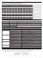
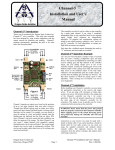
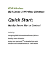
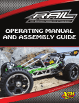
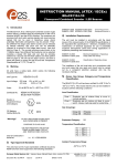
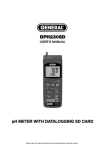
#96338
Sensored Brushless Competition ESC
User’s Guide
features and specifications
• Brushless Sensored Design w/Custom Sanwa Programming
• Motor Limit: 3.5T w/1S LiPo or 4.5T w/2S LiPo
• Adjustable Voltage Cutoff
• On Resistance: 0.00038 ohms
• Twelve Programming Modes (Red, Blue & Green Setup LEDs)
• Rated Current : 740 Amps/Phase @ 25ºC (77ºF)
• Thermal Overload Protection Circuit
• BEC: 6.0V/3.0A
• Compatible with Normal, SHR and SSR Channel Modes*
• Dimensions: 1.25 x 1.39 x 0.77” (32.0 x 35.5 x 19.7mm)
• Supports Remote Programming via Transmitter*
• Weight: 42g (Excluding Wiring and Power Capacitor)
• Input Power (Cells): 1S or 2S LiPo (4C to 6C Ni-Cd/Ni-MH)
*When used with compatible Airtronics or Sanwa transmitter and receiver.
what’s included
• Super Vortex Zero Competition ESC
• 3 Feet 12AWG Flexible Silicone Wire
• Sensor Cable
• Heat-Shrink Tubing
• Cooling Fan w/Mounting Screws
• User’s Guide
precautions and warnings
• This ESC is designed for use with Airtronics or Sanwa 2.4GHz radio systems. Functionality of this ESC with radio system brands other than
Airtronics or Sanwa may differ. Carefully check the function of the radio system when a brand other than Airtronics or Sanwa is used.
• This ESC is designed for use with 3.5T or greater (w/1S LiPo) and 4.5T or greater (w/2S LiPo) sensored brushless motors only.
• When soldering the motor and battery wires to the ESC, be careful not to overheat the mounting posts or damage can result.
• When soldering your battery connector and battery wires to the ESC, please observe correct polarity. Plugging the battery into the ESC
with reverse polarity will damage the ESC beyond repair! Use high-quality 4mm bullet connectors, Dean’s Ultra-Plug or similar.
• The power capacitor installed on the ESC is mandatory for proper use. Do not remove the power capacitor.
• Do not use a battery with a nominal input voltage greater than 7.4 volts (2S LiPo or 6C Ni-Cd/Ni-MH).
• If the ESC and/or your battery become hot, disconnect your battery from the ESC immediately and allow the ESC and/or your battery to
cool down before reconnecting.
• Mount the ESC using double-sided foam tape and in a position that allows for adequate airflow. If airflow is limited, install the included
cooling fan onto the ESC if room permits under your vehicle’s body.
• Turn your transmitter ON before turning the ESC ON and turn the ESC OFF before turning your transmitter OFF.
• Always disconnect your battery from the ESC when not in use.
• The ESC is not waterproof. Do not run through water or allow the ESC to become wet with moisture or the ESC can be damaged.
• Maintain your motor on a regular basis to ensure high performance. Degradation of motor performance can put undue stress on the ESC,
resulting in damage to the ESC.
overview, connections and mounting
To Battery
To
Motor B
To
To
Motor A
Motor C
Setup
Button
On/Off
Switch
Fan Input
Sensor Input
To Battery
Throttle Lead (to RX CH 2)*
*Blue (Signal)/Red (Positive)/Black (Negative)
Soldering Battery Wires and Motor Wires:
To Battery
Capacitor**
Setup LEDs
**Secure the capacitor to the battery wires or the chassis using a nylon cable tie (not included)
to prevent it from being damaged or from shaking loose during use.
IMPORTANT: When soldering your battery connector and battery wires to the ESC, please observe correct polarity - positive to positive
and negative to negative. When soldering the motor wires to the ESC and your motor, make sure that the wiring matches - A, B and C from
the ESC to A, B and C on your motor. Refer to the diagrams above.
1) Cut the silicone wire included into three lengths long enough to connect between the ESC and your motor, then two equal lengths long
enough to connect between the ESC and your battery. Strip approximately 3/32” to 1/8” of insulation off the ends of the wires to prepare
them for soldering. For optimum performance, the motor wires (A, B and C) should all be equal length.
2) Using a rosin-core solder and a sufficiently hot soldering iron, pre-tin the ends of each wire. To do this, heat the end of the wire and
apply solder until it is thoroughly covered. Next, pre-tin the battery mounting posts and motor mounting posts on the ESC by heating each
mounting post and applying enough solder to cover the mounting post with a thin layer of solder.
WARNING: Do not leave the soldering iron on the mounting posts for any longer than is necessary to melt the solder. If the mounting posts
overheat, it can damage the ESC. A suitably hot soldering should not be left on the mounting posts longer than about 5 seconds. If the
solder is not melting within about 5 seconds, use a hotter soldering iron.
3) While holding the tinned end of the wire in contact with the mounting post, hold the soldering iron in contact with both the wire and the
mounting post. Wait a couple of seconds for the solder to melt and flow between the two parts, then remove the soldering iron. Continue
to hold the wire in place for a couple of seconds, then let loose after the solder cools.
4) Repeat the previous procedures to solder the remaining wires to the ESC, then to solder the motor wires to your motor and the battery
wires to your battery connector (use high-quality 4mm bullet connectors, Dean’s Ultra-Plug or similar). We recommend that you use
heat-shrink tubing to insulate the solder joints between the battery wires and your battery connector(s).
1
overview, connections and mounting
Mounting the ESC:
1) Using two suitable sizes of double-sided foam tape, mount the ESC and the ESC On/Off switch to your model’s chassis.
2) Securely plug one end of the sensor cable into the Sensor Input socket on the ESC, then securely plug the other end of the sensor cable
into the Sensor Input socket on your motor. Both ends of the sensor cable are the same.
3) Plug the throttle lead into the throttle channel slot (usually channel 2) in your receiver, observing correct polarity - Blue (Signal), Red (Positive)
and Black (Negative). The plug is universal, so it should work with all modern major brand receivers.
IMPORTANT: When used with a receiver battery or a DC-Booster, please do not connect the pin of the positive terminal of the throttle lead
to the receiver throttle channel slot.
ESC Mounting Tips:
• For maximum efficiency, orientate the ESC so that the cooling fins are parallel to the airflow. Do not wrap the ESC in foam rubber or
in any way block airflow to the cooling fins.
• Install the On/Off switch on the chassis of your model in a location that’s convenient to access and that doesn’t interfere with any
moving parts. In addition, it may be necessary to secure the battery and/or motor wires to your chassis to prevent damage to them.
• Secure the capacitor to the ESC battery wires or the chassis using a nylon cable tie (not included) to prevent it from being damaged
or from shaking loose during use.
• In most cases, the use of the included cooling fan isn’t necessary, but in some cases, such as when there is limited airflow over the
ESC or if your using a higher than normal Timing Advance value, the cooling fan can help prevent the ESC from going into thermal
shutdown. When installing it, tighten the mounting screws (included) evenly to ensure you don’t warp the cooling fan.
transmitter setup and calibrating throttle end points
Prior to plugging in your battery and turning the ESC ON, set
up your transmitter as described in this section. This will ensure
proper ESC operation.
1) Adjust your transmitter’s throttle channel D/R, EPA, EXP, ARC,
Sub-Trim and Servo Reversing settings to the values shown
in the table at right. Refer to your transmitter’s User’s Guide for
information about changing these settings. Not all transmitters
may support all options.
Throttle Channel High Side and Brake Side D/R
100%
Throttle Channel High Side and Brake Side EPA
100%
Throttle Channel High Side and Brake Side EXP
OFF or 0%
Throttle Channel High Side and Brake Side ARC
OFF or 0%
Throttle Channel Sub-Trim
0 or Centered
Throttle Channel Servo Reversing*
NOR or REV
The steps below assume your transmitter and receiver have already been paired. Although in most cases it’s possible to bind your transmitter
and receiver with the ESC powering your receiver, in some cases you may need to unplug the ESC and bind your transmitter and receiver
using a separate receiver battery pack. Once the binding procedure is complete, you can unplug the separate battery pack and plug the
ESC back into you receiver.
WARNING: To prevent any chance of a runaway model, or damage or injury during the calibration process, remove the pinion gear from your
motor. After completing the calibration process, reinstall the pinion gear.
*Do not change after calibration.
1
2
3
4
5
Verify that the ESC On/Off switch is turned OFF.
With the throttle trigger in the neutral position, turn your transmitter ON, then plug your fully-charged battery into the ESC, making sure
to observe correct polarity.
ON
Turn the ESC On/Off switch ON.
Push
Press and hold the Setup Button. The Setup LED will turn solid green.
With the throttle trigger in the neutral position, press the Setup
Button. The Setup LED will turn solid blue, indicating the throttle
neutral position is stored.
While holding the throttle trigger in the full throttle position, press
the Setup Button. The Setup LED will turn solid red, indicating the
full throttle position is stored. Release the throttle trigger.
While holding the throttle trigger in the full brake position, press
the Setup Button. The Setup LEDs will turn solid red, blue and
green, indicating the full brake position is stored and the calibration
process is complete. Release the throttle trigger.
Press
Neutral
Press
Full Throttle
Press
Full Brake
IMPORTANT: The steps above only need to be done once, unless you change transmitters or make changes to your transmitter’s throttle
channel preferences, in which case you should repeat the calibration steps. After calibrating the throttle end points, increasing throttle
channel EPA will not increase motor speed, however, decreasing throttle channel EPA will.
led throttle position condition indicators
When the throttle trigger is moved, the Setup LEDs will
illuminate solid, flash or flash rapidly, allowing you to
visually verify ESC performance relative to throttle trigger
position. This ensures your throttle is working and
calibrated correctly throughout the entire range of
deflection in both directions.
Use the table at right to determine the throttle trigger
position based on the Setup LED condition.
2
Throttle Trigger Position
Neutral (with Advanced Timing OFF)
Neutral (with Advanced Timing ON)
Setup LED
Flashing Blue
Solid Blue
Any Throttle Setting Other Than Full (SSR Mode)
Flashing Blue Rapidly
Any Throttle Setting Other Than Full (NOR/SHR Mode)
Flashing Red Rapidly
Full Throttle
Any Brake or Reverse Setting Other Than Full
Full Brake or Full Reverse
Solid Blue
Flashing Red Rapidly
Solid Red
changing programming mode values
The Super Vortex Zero supports twelve different Programming Modes with various Programming Mode Values that can be changed to suit your
specific needs. The Setup LEDs will flash to indicate the current Programming Mode and Programming Mode Value:
Blue and Red LED - The number of blue LED flashes indicates the current Programming Mode you’re in. The LED will flash red when you
enter the Setup Mode to change Programming Mode Values.
Green LED - The number of flashes indicates the current Programming Mode Value within the Programming Mode.
The Super Vortex Zero functions in three different modes as described:
Operating Mode - This mode is used under normal operating conditions (e.g., when you’re driving your model).
Programming Mode - This mode is used to choose one of the twelve available Programming Modes.
Setup Mode - This mode is used to choose one of the various Programming Mode Values within a chosen Programming Mode.
1
Enter Programming Mode
Press and HOLD the Setup Button for 4 seconds or more. The Setup LEDs will flash, indicating the ESC is
in Programming Mode. Release the Setup Button.
2
Changing Programming
Modes
Press the Setup Button to cycle through the twelve different Programming Modes. The blue LED will flash a
specific number of times, indicating the current Programming Mode and the green LED will flash a specific
number of times, indicating the current Programming Mode Value within that Programming Mode.
3
4
From within the desired Programming Mode, press and HOLD the Setup Button for 2 seconds or more to
enter the Setup Mode. The red and green LEDs will both flash a specific number of times, indicating the
current Programming Mode Value.
Changing Programming
Mode Values
(Setup Mode)
Press the Setup Button to choose the desired Programming Mode Value. The red and green LEDs will
flash a specific number of times, indicating the new current Programming Mode Value you chose.
After choosing the desired Programming Mode Value, press and HOLD the Setup Button for 2 seconds
or more to return to the Programming Mode as described in step 2 above. Repeat steps 2 and 3 to select
another Programming Mode and change its Programming Mode Value.
From within the Programming Mode, press the Setup Button to cycle through the twelve Programming
Modes and return to the Operating Mode. The Setup LEDs will turn solid (if Timing Advance is Enabled) or
flash blue (if Timing Advance is Disabled), indicating your Programming Mode Values have been saved.
Saving Programming
Mode Values
IMPORTANT: If you don’t want to save your Programming Mode Values, turn the ESC OFF and back ON
before returning to the Operating Mode as described.
ESC Programming Flow Chart:
Programming Modes and Programming Mode Values:
MODE 1 (Cut-Off Voltage) Ensure that the Cut-Off Voltage value you choose matches the battery type you’re using.
#1
#2
#3
#4
#5
#6
#7
#8
#9
#10
#11
OFF
3.0v
3.3v
3.6v
4.0v
4.4v
4.8v
5.2v
5.6v
6.0v
6.4v
MODE 2 (Reverse) Enable or Disable Reverse function. Reverse is 50% of speed of forward.
#1
#2
Disabled
Enabled
MODE 3 (Thermal Protection) ESC and motor over-heat protection. Requires motor be equipped with temperature sensor.
#1
#2
#3
#4
#5
#6
120ºC/80ºC
120ºC/90ºC
120ºC/100ºC
120ºC/110ºC
120ºC/120ºC
OFF/OFF
MODE 4 (Timing Advance) After Enabling, allows adjustment of Boost Rate, Turbo and Power Mode.
#1
#2
Disabled
Enabled
MODE 5 (Full Brake Rate) Adjust the maximum brake setting without using transmitter Brake Side EPA.
#1
#2
#3
#4
#5
#6
#7
#8
#9
#10
#11
100%
90%
80%
70%
60%
50%
40%
30%
20%
10%
0%
MODE 6 (Drag Brake) Changes the braking effectiveness as the throttle trigger is returned to neutral.
#1
#2
#3
#4
#5
#6
#7
#8
#9
#10
#11
0%
5%
10%
15%
20%
25%
30%
35%
40%
45%
50%
MODE 7 (Feel) Higher values increase the smoothness of the throttle in the forward and return to neutral directions.
#1
#2
#3
#4
#5
#6
#7
#8
#9
#10
#11
0
10
20
30
40
50
60
70
80
90
100
*Default values are shown in gray.
IMPORTANT:
The cut-off voltage you choose
should not be set lower than
recommended for your battery,
particularly when using LiPo
batteries. Refer to your battery
specifications for the correct
cut-off voltage to use. Setting
too low a value can damage
your battery. For LiPo batteries,
3.2v per cell is a safe value.
The first Thermal Protection
temperature value relates to
ESC temperature and the second
temperature value relates to
motor temperature. When the
temperature of the ESC and/
or motor reaches the specified
value, the motor will slow down
and the Boost function will not
work. Once the temperature
cools 20ºC below the specified
value, the function will return to
normal. If the motor does not
feature a built-in temperature
sensor, motor thermal protection
will not work.
Timing Advance must be
Enabled to see changes made
to Boost Rate/Timing Advance
Rate, Turbo and Power Mode
settings.
3
changing programming mode values
Programming Modes and Programming Mode Values, Continued:
MODE 8 (Drag Brake Feel) Higher values increase the smoothness of the Drag Brake function.
#1
#2
#3
#4
#5
#6
#7
#8
#9
#10
#11
0
10
20
30
40
50
60
70
80
90
100
MODE 9 (Brake Feel) Higher values increase the smoothness of throttle in the brake and return to neutral directions.
#1
#2
#3
#4
#5
#6
#7
#8
#9
#10
#11
0
10
20
30
40
50
60
70
80
90
100
MODE 10 (Boost Rate/Timing Advance) Higher values increase motor performance throughout the entire throttle range.
#1
#2
#3
#4
#5
#6
#7
#8
#9
#10
#11
0%
10%
20%
30%
40%
50%
60%
70%
80%
90%
100%
MODE 11 (Turbo) Increases the Timing Advance value at only the full throttle position by the percentage chosen.
#1
#2
#3
#4
#5
#6
#7
#8
#9
#10
#11
0%
2%
4%
6%
8%
10%
12%
14%
16%
18%
20%
MODE 12 (Power Mode) Adjusts the starting position of the Boost function.
#1
#2
#3
#4
#5
#6
#7
#8
#9
#10
#11
P-M0
P-M1
P-M2
P-M3
P-M4
P-M5
P-M6
P-M7
P-M8
P-M9
P-M10
IMPORTANT:
Increasing Boost Rate/Timing
Advance, Turbo and Power
Mode values can result in
damage to your motor and/or
ESC from excessive heat. Values
should be adjusted in single
increments and you should
check the temperature of the
ESC and your motor after each
adjustment.
Using higher Power Mode
values will cause the Boost
function to start working at a
lower throttle position. When
using a modified motor, we
don’t suggest using a value
higher than # 5. When using a
stock motor, any value can be
used, but you must check your
ESC and motor temperatures to
ensure they’re not overheating.
led operating error descriptions
If the ESC detects an error during use, the Setup LEDs can be used to determine what the error is and what may cause it.
Setup LED Condition
Error
Flashing Red, Blue & Green
No Signal
Possible Cause
The transmitter is turned OFF or the ESC is not plugged into the receiver correctly.
Slowly Flashing Blue & Red
Abnormal Motor Rotation
Slowly Flashing Red & Green
Low Battery
The battery voltage is below the Voltage Cut-Off limit or the battery could be damaged.
Flashes x 1 Red
Sensor Error
The sensor cable is unplugged or damaged, or the motor and/or motor sensors are damaged.
Flashes x 2 Red
Flashes x 3 Red
Flashes x 4 Red
Damaged motor and/or motor sensors. Also check sensor cable.
Thermal Protection of FET The ESC has overheated and the thermal protection feature has shut it down. Ensure Power Mode,
Thermal Protection of Motor gear ratio and Timing Advance are not too high. Ensure the number of turns of the motor is not too low.
Thermal Protection of BEC The BEC has been overloaded. Check cooling fan (install if necessary), servo(s) and other equipment.
troubleshooting
Problem
Cause
Servo(s) work, but motor does ESC not connected properly
not run
Thermal protection Activated
Wire or connector is disconnected
Motor wires are connected incorrectly
Motor is damaged
ESC is damaged
Servo(s) do not work
Transmitter and receiver not paired
ESC not connected properly
Battery is completely drained
ESC is not turned ON
ESC is damaged
Transmitter is set up incorrectly
Motor runs slowly or has no Pinion gear is too large for motor
acceleration
Battery is faulty or motor is damaged
ESC is damaged
ESC is overheating and going Inadequate cooling
into thermal shutdown
Battery nominal voltage too high
Incorrect gearing or binding in drive-train
Timing Advance value set too high
Damaged motor
ESC works intermittently
ESC going into thermal shutdown
Loose connection
ESC is damaged
Solution
Plug ESC into channel 2 and verify all connections and polarity
Allow ESC to cool down sufficiently
Verify that all connections are tight and secure
Reconnect motor wires correctly per diagram on front page
Replace or repair motor
Contact Service and Support (see below)
Pair (bind) transmitter and receiver
Plug ESC into channel 2 and verify all connections and polarity
Charge battery fully
Turn ESC ON
Contact Service and Support (see below)
Set up transmitter and calibrate end points as described on page 2
Use smaller pinion gear
Replace battery or repair or replace motor
Contact Service and Support (see below)
Improve cooling for ESC or use optional cooling fan
Use recommend battery
Adjust gearing or repair drive-train
Lower Timing Advance value or turn Timing Advance OFF
Repair or replace motor
Improve cooling for ESC or use optional cooling fan
Check all connections to ensure they’re tight
Contact Service and Support (see below)
service and support
Your Airtronics Super Vortex Zero Sensored Brushless Competition ESC is warranted against manufacturer defects in materials and
workmanship, at the original date of purchase. This warranty does not cover suitability for specific application, components worn by use or
improper voltage, tampering, modification, misuse, abuse, improper wiring, reverse polarity or moisture damage.
For additional warranty and service information, please visit http://www.airtronics.net/index.php/service.
Airtronics is Imported Exclusively in North America by:
Global Hobby Distributors
18480 Bandilier Circle
Fountain Valley, CA 92708
Telephone: (714) 963-0329
Fax: (714) 964-6236
Email: [email protected]
Features and Specifications are Subject to Change Without Notice. All contents © 2013 Airtronics, Inc. All Rights Reserved. Revision 1 03.22.2013
4
670A02352A