1
AEROFLEX GAISLER
582
GRIP
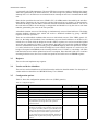
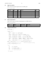
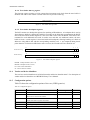
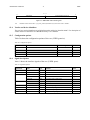
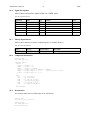
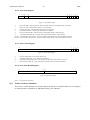
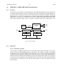
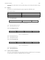
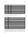
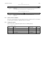
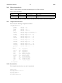
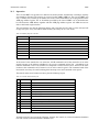
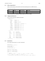
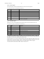
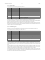
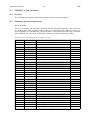
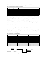
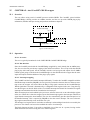
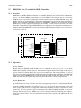
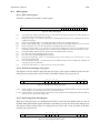
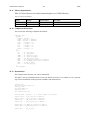
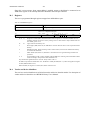
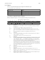
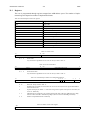
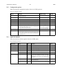
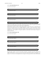
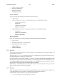
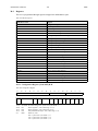
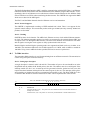
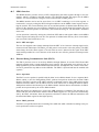
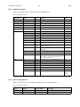
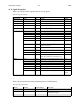
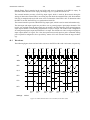
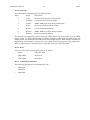
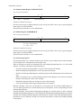
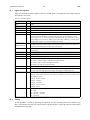
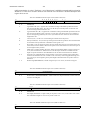
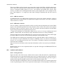
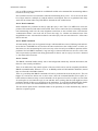
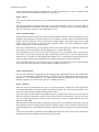
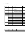
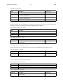
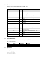
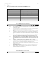
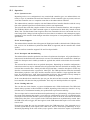
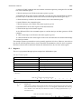
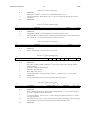
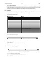
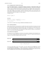
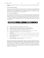
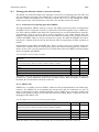
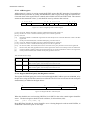
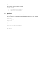
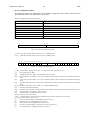
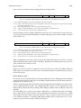
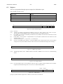
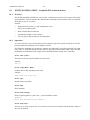
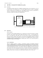
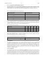
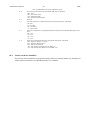
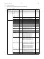
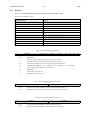
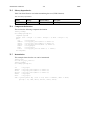
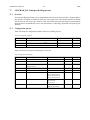
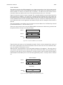
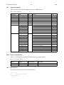
58.3.1 Status register
31
usereg
30
qualifier
29
armed
28
trigged
27
20
19
dbits
6
5
depth
0
trig levels
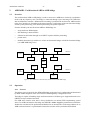
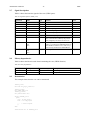
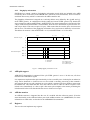
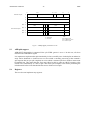
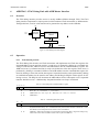
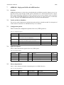
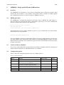
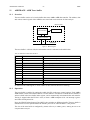
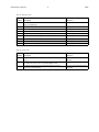
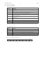
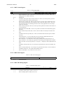
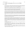
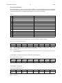
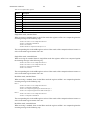
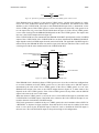
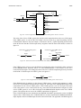
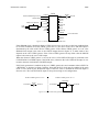
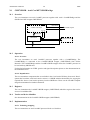
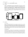
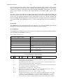
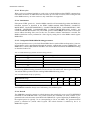
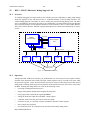
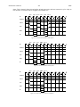
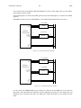
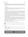
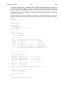
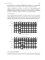
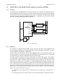
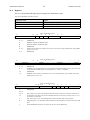
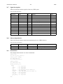
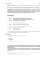
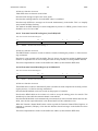
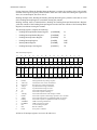
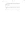
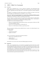
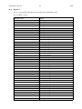
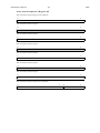
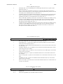
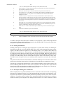
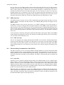
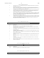
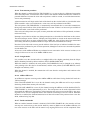
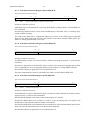
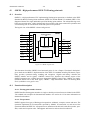
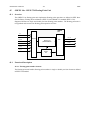
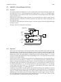
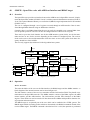
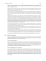
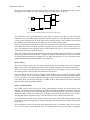
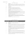
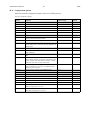
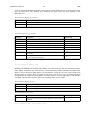
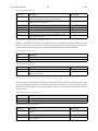
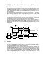
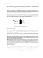
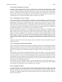
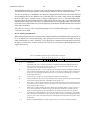
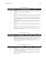
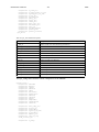
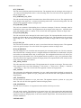
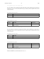
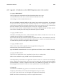
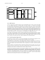
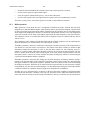
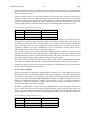
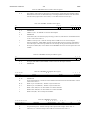
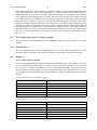
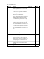
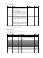
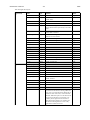
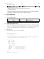
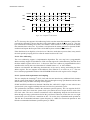
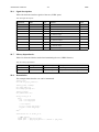
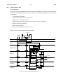
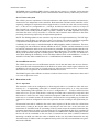
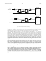
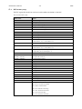
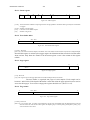
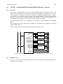
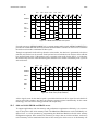
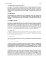
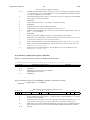
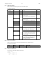
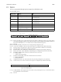
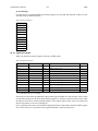
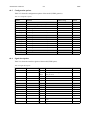
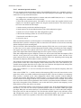
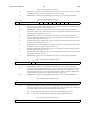
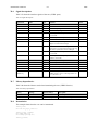
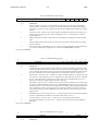
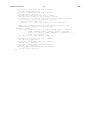
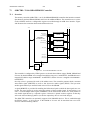
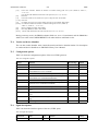
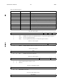
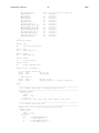
Figure 192. Status register
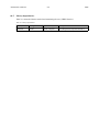
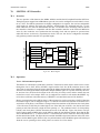
[31:28] These bits indicate whether an input register and/or storage qualifier is used and if the Logic Analyzer is armed and/
or trigged.
[27:20] Number of traced signals.
[19:6] Last index of trace buffer. Depth-1.
[5:0]
Number of trig levels.
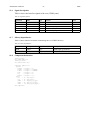
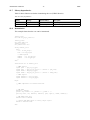
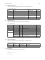
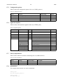
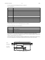
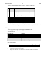
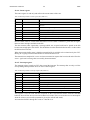
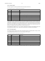
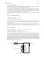
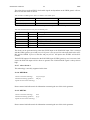
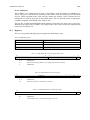
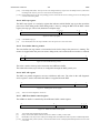
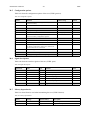
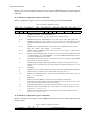
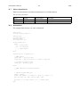
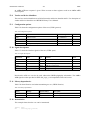
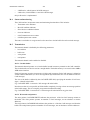
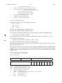
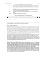
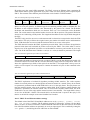
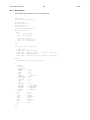
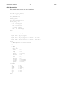
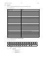
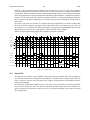
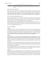
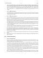
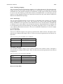
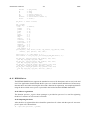
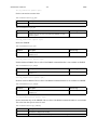
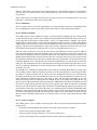
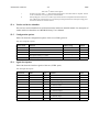
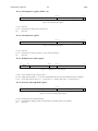
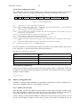
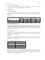
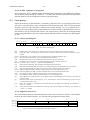
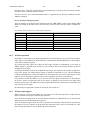
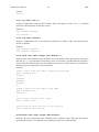
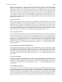
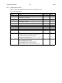
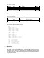
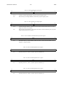
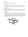
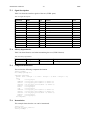
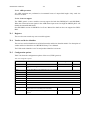
58.3.2 Trace buffer index
31
abits abits-1
“000...0”
0
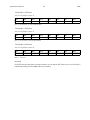
the index of the oldest sample
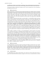
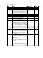
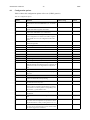
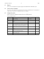
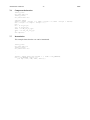
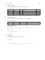
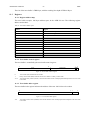
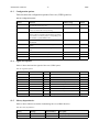
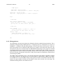
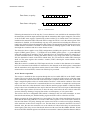
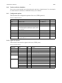
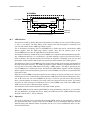
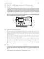
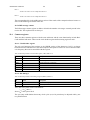
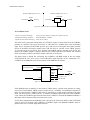
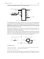
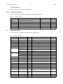
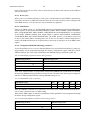
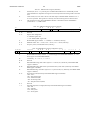
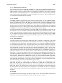
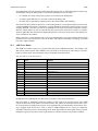
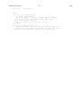
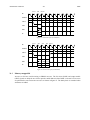
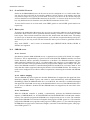
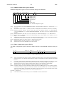
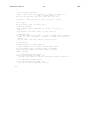
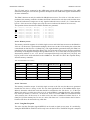
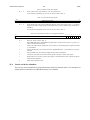
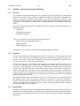
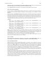
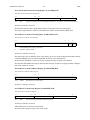
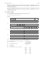
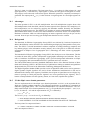
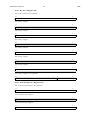
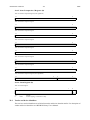
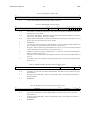
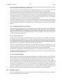
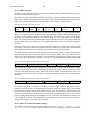
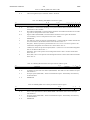
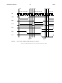
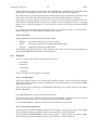
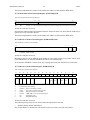
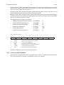
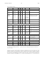
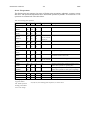
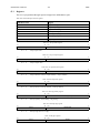
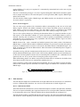
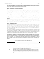
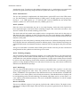
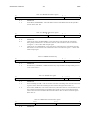
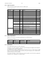
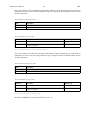
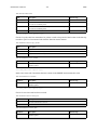
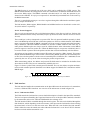
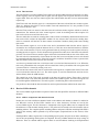
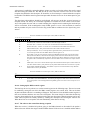
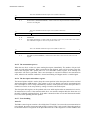
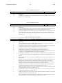
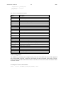
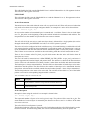
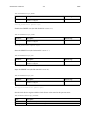
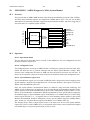
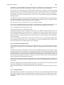
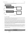
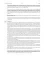
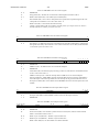
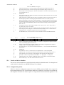
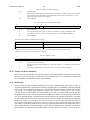
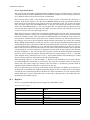
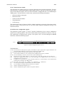
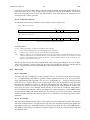
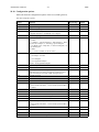
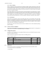
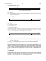
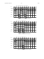
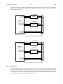
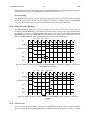
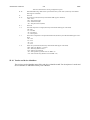
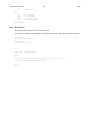
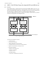
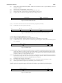
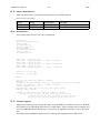
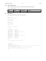
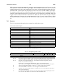
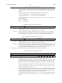
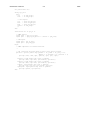
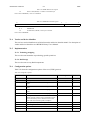
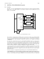
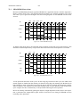
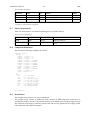
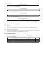
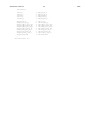
Figure 193. Trace buffer index register
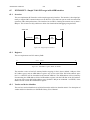
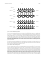
[31:abits] - Reserved.
[abits-1:0] - The index of the oldest sample in the buffer. abits is the number of bits needed to represent the configured depth.
Note that this register is written by the trigger engine clock domain and thus needs to be known stable
when read out. Only when the ‘armed’ bit in the status register is zero is the content of this register
reliable.
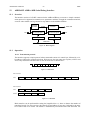
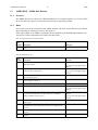
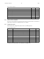
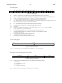
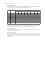
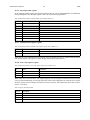
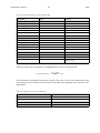
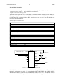
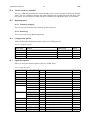
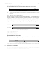
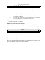
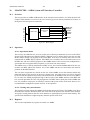
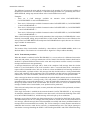
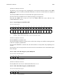
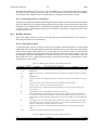
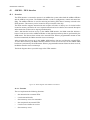
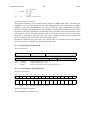
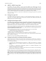
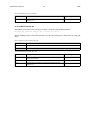
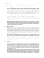
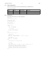
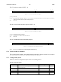
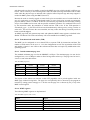
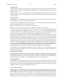
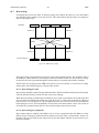
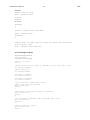
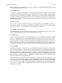
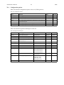
58.3.3 Page register
4 3
31
0
current page
“000...0”
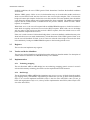
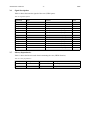
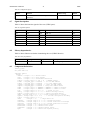
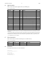
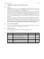
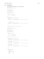
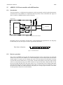
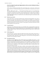
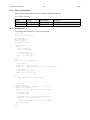
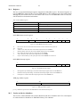
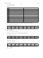
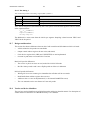
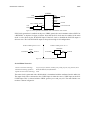
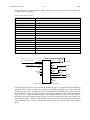
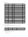
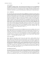
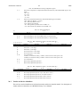
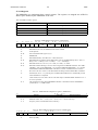
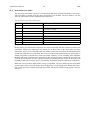
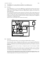
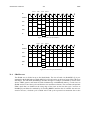
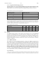
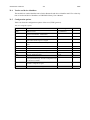
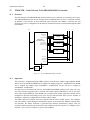
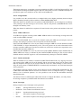
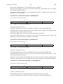
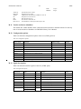
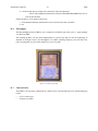
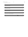
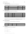
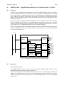
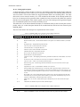
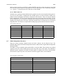
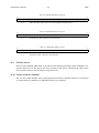
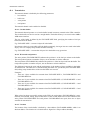
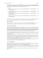
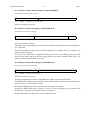
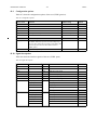
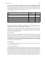
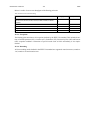
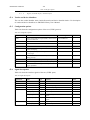
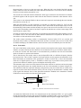
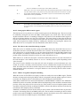
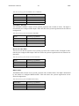
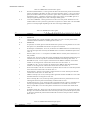
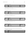
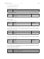
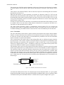
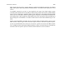
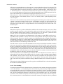
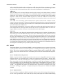
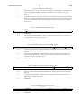
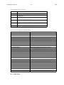
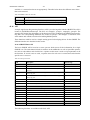
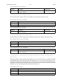
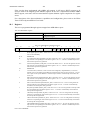
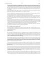
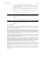
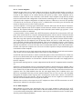
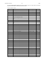
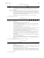
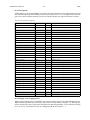
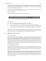
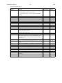
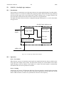
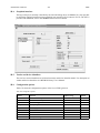
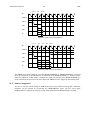
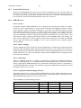
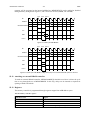
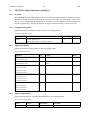
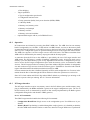
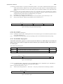
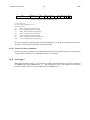
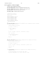
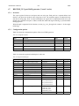
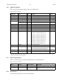
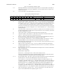
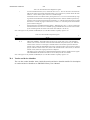
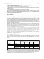
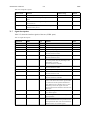
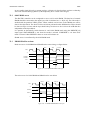
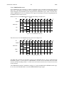
Figure 194. Page register
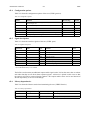
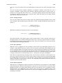
[31:4] - Reserved.
[3:0] - This register selects what page that will be used when reading from the trace buffer.
The trace buffer is organized into pages of 1024 samples. Each sample can be
between 1 and 256 bits. If the depth of the buffer is more than 1024 the page register has to be used to
access the other pages. To access the i:th page the register should be set i (where i=0..15).
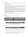
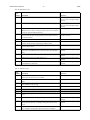
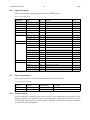
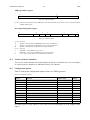
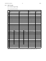
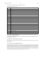
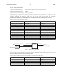
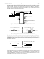
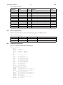
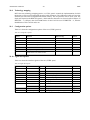
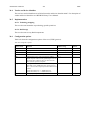
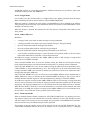
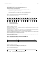
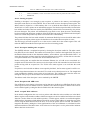
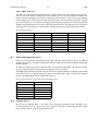
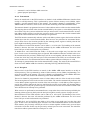
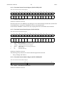
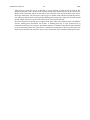
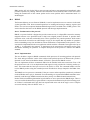
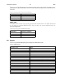
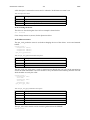
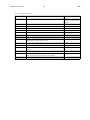
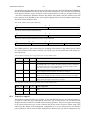
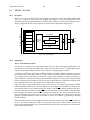
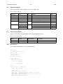
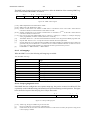
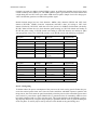
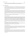
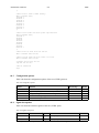
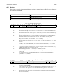
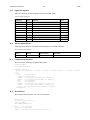
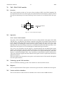
58.3.4 Trig counter
31
abits abits-1
“000...0”
0
trig counter value
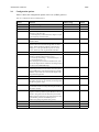
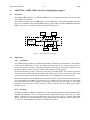
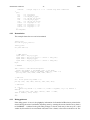
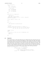
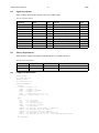
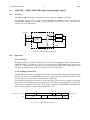
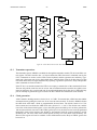
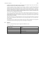
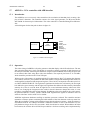
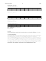
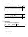
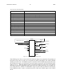
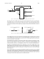
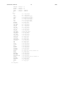
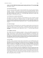
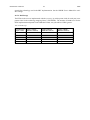
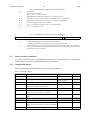
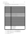
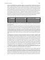
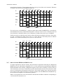
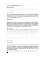
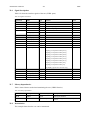
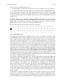
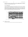
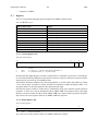
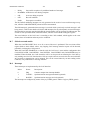
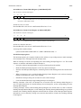
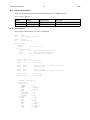
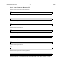
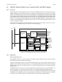
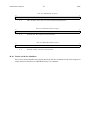
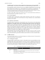
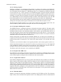
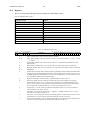
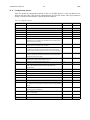
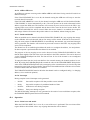
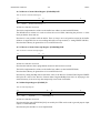
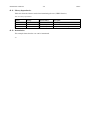
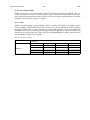
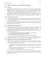
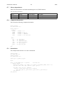
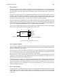
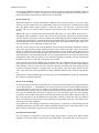
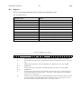
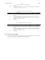
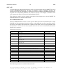
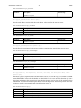
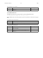
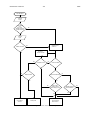
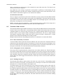
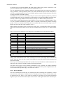
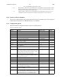
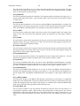
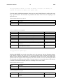
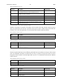
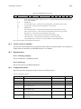
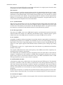
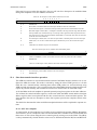
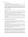
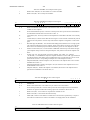
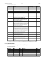
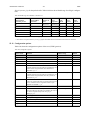
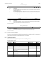
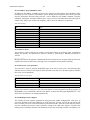
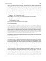
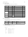
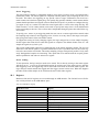
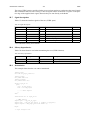
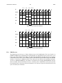
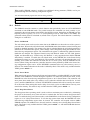
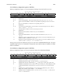
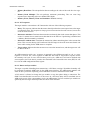
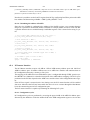
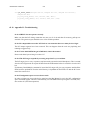
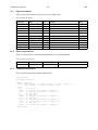
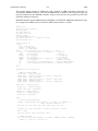
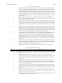
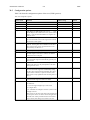
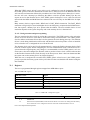
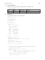
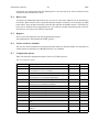
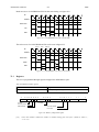
Figure 195. Trig counter register
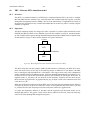
[31:abits] - Reserved.
[nbits-1:0] - Trig counter value. A counter is incremented by one for each stored sample after the final triggering event and
when it reaches the value stored in this register the sampling stops. 0 means posttrig and depth-1 is pretrig. Any
value in between can be used.