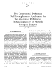
1
GE Healthcare
Typhoon Trio
User’s Guide Addendum
Version 5.0 for Microsoft Windows
Important User Information!
CE Certification
All users must read this entire manual to fully understand
the safe use of Typhoono Trio.
IMPORTANT! Typhoon Trio is intended for laboratory use
only, not for clinical or in vitro use, or for diagnostic purposes.
This product complies with the European directives listed
below, by fulfilling corresponding standards.
A copy of the Declaration of Conformity is available on
request.
• 73/23/EEC, Low Voltage Directive
• 89/336/EEC, EMC Directive
The CE logo and corresponding declaration of conformity,
is valid for the instrument when it is:
• used as a stand-alone unit, or
• connected to other CE-marked GE Healthcare instruments, or
• connected to other products recommended or described
in this manual, and
• used in the same state as it was delivered from GE
Healthcare except for alterations described in this manual.
WARNING!
The WARNING! sign highlights instructions that must be followed to avoid personal injury. It is important not to
proceed until all stated conditions are
met and clearly understood.
CAUTION!
The CAUTION! sign highlights instructions that must be
followed to avoid damage to the product or other equipment. It is important not to proceed until all stated conditions are met and clearly understood.
IMPORTANT!
The IMPORTANT! sign highlights information that is critical
for optimal performance of the system.
Note!
The Note sign is used to indicate information important
for trouble-free and optimal use of the product.
Recycling
This symbol indicates that the waste of electrical and electronic equipment must not be
disposed as unsorted municipal waste and
must be collected separately. Please contact
an authorized representative of the manufacturer for information concerning the decommissioning of your equipment.
WARNING!
This is a Class A product. In a domestic environment this
product may cause radio interference in which case the
user may be required to take adequate measures.
WARNING!
All repairs should be done by personnel authorized by GE
Healthcare. Do not open any covers or replace any parts
unless specifically stated in the instructions.
WARNING!
If liquid is spilled on the equipment, the power supply shall
be disconnected immediately.
Note: The Declaration of conformity is valid only for
systems that are marked with the CE logo:
Contents
Table of contents
Preface
1 Introduction
1.1 Site requirements .................................................................................................... 12
1.2 System components and optional accessories ........................................ 12
1.2.1
System components....................................................................................... 12
1.2.2
Optional accessories...................................................................................... 13
1.3 Scan acquisition modes ....................................................................................... 13
1.4 Before using the system ...................................................................................... 13
2 Safety
2.1 Safety overview ........................................................................................................ 15
2.2 Laser light safety ..................................................................................................... 15
3 Fluorescence scanning
3.1 Excitation modes ..................................................................................................... 17
3.2 Emission filters .......................................................................................................... 18
3.3 About the Fluorescence Setup window ........................................................ 19
3.3.1
Displaying the Fluorescence Setup window........................................ 19
3.3.2
Selecting the emission filter ........................................................................ 20
3.3.3
Selecting the laser........................................................................................... 21
4 Troubleshooting
4.1 Recycling ..................................................................................................................... 23
5 Technical Specifications
5.1 Regulatory requirements ..................................................................................... 25
5.2 Technical data .......................................................................................................... 25
Typhoon Trio Users Guide Addendum 00-4278-46 Edition AB
5
Contents
6
Typhoon Trio Users Guide Addendum 00-4278-46 Edition AB
Preface
Preface
About this addendum
The Typhoon Trio User’s Guide Addendum v 5.0 provides an overview of the
Typhoon™ Trio and the Typhoon Trio+ model instruments. This addendum
describes only the features and functions that differ from the Typhoon instrument
models described in the Typhoon User’s Guide v 3.0. You should use this
addendum in conjunction with the user’s guide to learn how to operate and
maintain the Typhoon Trio or the Typhoon Trio+ system.
Related publications
In addition to the Typhoon Trio User’s Guide Addendum, Typhoon User’s Guide,
and Typhoon Installation Instructions, you should be familiar with the
ImageQuant™ TL image analysis software.
Safety
Chapter 2 in this addendum and chapter 2 in the Typhoon User’s Guide provide
important safety information that should be used when operating the Typhoon
system. Before using the Typhoon system, read and understand the safety
information thoroughly.
Special safety text
Make sure you follow the precautionary statements presented in this guide.
WARNING! Indicates a possibility of severe or fatal injury to the user
or other persons if the precautions or instructions are not observed.
CAUTION! Indicates that damage to the instrument, loss of data, or invalid data
could occur if the user fails to comply with the advice given.
IMPORTANT! Highlights information that is critical for optimal performance of the
system.
Note: Identifies items of general interest.
Typhoon Trio User Guide Addendum 00-4278-46 Edition AB
7
Preface
Trained operator
WARNING! The operator of the Typhoon system is assumed to be trained in
the correct operation of the system and the safety issues. Throughout the
Typhoon Trio User’s Guide Addendum and the Typhoon User’s Guide, the word
“you” refers to this trained operator.
Assumptions
The software-related instructions in this addendum assume you have basic
computer skills. You should be familiar with the Microsoft™ Windows™ graphical
user interface. If you do not have these skills, refer to the documentation or the
Help for Windows.
Safety standards
Compliance with standards
The declaration of conformity is valid for the instrument only if it is:
•
used in laboratory locations
•
used in the same state as it was delivered from GE Healthcare except for
alterations described in the User Manual
•
connected to other CE labelled GE Healthcare modules or other products as
recommended.
Safety standards:
This product meets the requirement of the Low Voltage Directive (LVD) 73/23/EEC
through the following harmonized standards:
8
•
EN 61010-1
•
IEC 61010-1
•
CAN/CSA-C22.2 No. 61010-1
•
UL61010-1
Typhoon Trio User Guide Addendum 00-4278-46 Edition AB
Preface
EMC standards
This device meets the requirements of the EMC Directive 89/336/EEC through the
following harmonized standards:
•
EN 61326 (emission and immunity)
•
EN 55011, GR 2, Class A (emission)
This device complies with part 15 of the FCC rules (emission). Operation is subject
to the following two conditions:
1 This device may not cause harmful interference.
2 This device must accept any interference received, including interference that
may cause undesired operation.
Typhoon Trio User Guide Addendum 00-4278-46 Edition AB
9
Preface
Asia Pacific
Tel +85 65 62751830
Fax +85 65 62751829
Japan
Tel 81 3 5331 9336
Fax 81 3 5331 9370
Australasia
Tel +61 2 8820 8299
Fax +61 2 8820 8200
Korea
Tel 82 2 6201 3700
Fax 82 2 6201 3803
Austria
Tel 01 /57606 1613
Fax 01 /57606 1614
Latin America
Tel +55 11 3933 7300
Fax +55 11 3933 7304
Belgium
Tel 0800 73 890
Fax 02 416 8206
Middle East & Africa
Tel +30 210 96 00 687
Fax +30 210 96 00 693
Canada
Tel 1 800 463 5800
Fax 1 800 567 1008
Netherlands
Tel 0800-82 82 82 1
Fax 0800-82 82 82 4
Central & East Europe
Tel +43 1 972 720
Fax +43 1 972 722 750
Norway
Tel +47 815 65 777
Fax +47 815 65 666
Denmark
Tel +45 70 25 24 50
Fax +45 45 16 2424
Portugal
Tel 21 417 7035
Fax 21 417 3184
Eire
Tel 1 800 709992
Fax +44 1494 542010
Russia, CIS & NIS
Tel +7 495 956 5177
Fax +7 495 956 5176
Finland & Baltics
Tel +358 9 512 3940
Fax +358 9 512 39439
Spain
Tel 902 11 72 65
Fax 935 94 49 65
France
Tel 01 69 35 67 00
Fax 01 69 41 98 77
Sweden
Tel 018 612 1900
Fax 018 612 1910
Germany
Tel 0800 9080 711
Fax 0800 9080 712
Switzerland
Tel 0848 8028 10
Fax 0848 8028 11
Greater China
Tel +852 2100 6300
Fax +852 2100 6338
UK
Tel 0800 515 313
Fax 0800 616 927
Italy
Tel 02 26001 320
Fax 02 26001 399
USA
Tel +1 800 526 3593
Fax +1 877 295 8102
Assistance
When calling for assistance, be prepared to supply the serial number of your
instrument. For contact by phone or fax, please use one of the numbers below.
Alternatively, an updated list of contacts is available on the Web at
www.gehealthcare.com.
10
Typhoon Trio User Guide Addendum 00-4278-46 Edition AB
Introduction 1
1
Introduction
The Typhoon Trio instrument is a variable-mode imager that produces digital
images of radioactive, fluorescent, or chemiluminescent samples. The Typhoon
system consists of an instrument (figure 1-1), instrument control software, and a
variety of accessories. The Typhoon instrument is available in several models. This
addendum provides an overview of the Typhoon Trio and Typhoon Trio+ models.
The Typhoon Trio instrument contains three internal lasers (blue, green, and red).
The Typhoon Trio+ is a Typhoon Trio instrument with the additional 10-µm pixel
size scanning resolution.
The topics in this chapter are—
•
Site requirements (section 1.1)
•
System components and optional accessories (section 1.2)
•
Scan acquisition modes (section 1.3)
•
Before using the system (section 1.4)
Fig 1-1. The Typhoon Trio instrument.
For a detailed description of how to use the Typhoon Trio system, see the Typhoon
User's Guide.
Typhoon Trio User Guide Addendum 00-4278-46 Edition AB
13
1 Introduction
1.1 Site requirements
1.1
Site requirements
Table 1-1 provides a summary of the Typhoon Trio instrument site requirements.
For additional site guidelines, see the Typhoon Installation Instructions for the
Microsoft Windows XP Workstation.
Table 1-1. Typhoon Trio system instrument specifications
Parameter
Power requirements
Value
100–120 V~, 6 A, 50/60 Hz
220–240 V~, 4 A, 50/60 Hz
Weight
Approximately 160 kg (350 lb)
Dimensions
Width:
118.11 cm (46.5 in)
Height:
48.26 cm
(19 in)
Depth:
77.47 cm
(30.5 in)
Temperature
15–30 °C (59–86 °F)
Humidity
Noncondensing 10%–80% relative humidity
1.2
System components and optional accessories
1.2.1
System components
The Typhoon Trio system includes the Typhoon Trio or Typhoon Trio+ instrument,
Scanner Control software, Typhoon Direct Instrument Access software, Ethernet™
cables, power cords, and tools. The Typhoon instrument connects to the
computer using an Ethernet connection.
The Typhoon Trio instrument contains the following three internal lasers:
•
Blue laser—A solid-state laser with a specified minimum output of
20 mW at 488 nm in a diverging beam.
•
Green laser—A green visible laser with a specified minimum output of
20 mW at 532 nm in a diverging beam.
•
Red laser—A red visible laser with a specified minimum of 10 mW at
633 nm in a diverging beam.
The Scanner Control software, which runs on the Microsoft Windows operating
system, contains the graphical interface that allows you to control the
instrument. In addition, Internet Explorer is required for the Typhoon Direct
Instrument Access software. You use the Typhoon Direct Instrument Access
software to perform several maintenance procedures, which are described in the
Typhoon User's Guide.
14
Typhoon Trio User Guide Addendum 00-4278-46 Edition AB
Introduction 1
1.2.2
Optional accessories
See the Typhoon User’s Guide for a description of the optional accessories for the
storage phosphor and fluorescence scanning modes. In addition, the Typhoon
multislide tray is available for the Typhoon Trio+ instrument. The multislide tray
allows you to scan up to 30 microarray slides at a time. See the Typhoon Multislide
User’s Guide for a description of how to use the multislide tray.
1.3
Scan acquisition modes
You can scan samples on the Typhoon Trio or Typhoon Trio+ instrument using the
following scan acquisition modes:
•
Storage phosphor mode—Creates images from samples labelled with
radioisotopes using storage phosphor technology.
•
Fluorescence mode—Creates images from samples labelled with
fluorescent dyes. For details on the available excitation modes, see
chapter 3.
•
Chemiluminescence mode—Creates images from chemiluminescent
samples.
1.4
Before using the system
Before using the Typhoon Trio system, you should become familiar with—
•
Safety information—It is imperative that you follow the precautions in
this addendum and in the Typhoon User's Guide, chapter 2.
•
Basic operational instructions—See the Typhoon User's Guide.
•
Maintenance information for the instrument and accessories—See the
Typhoon User's Guide.
Typhoon Trio User Guide Addendum 00-4278-46 Edition AB
15
1 Introduction
1.4 Before using the system
16
Typhoon Trio User Guide Addendum 00-4278-46 Edition AB
Safety 2
2
Safety
WARNING! The operator of the Typhoon system is assumed to be trained in the
correct operation of the system and the safety issues. Throughout the Typhoon
User’s Guide and this addendum, the word “you” refers to this trained operator.
Using controls, making adjustments, or performing procedures other than
those specified in the Typhoon User’s Guide or this addendum can result in
hazardous exposure to laser light, high voltage, or moving parts. Exposure to
these hazards can cause severe injury or death.
2.1
Safety overview
Make sure you understand and follow the safety precautions in the Typhoon User’s
Guide, including—
•
General safety precautions
•
Typhoon serial numbers and safety labels
•
Electrical safety
•
Pinching and general warnings
•
Hazardous materials precautions
See section 2.2 of this addendum for laser light safety.
2.2
Laser light safety
The Typhoon Trio instrument is a Class I laser instrument that houses three Class IIIB
lasers: blue, green, and red. Under the specified operating procedures, the
instrument does not allow operator exposure to laser light. However, the lasers are
accessible in the interior of the instrument. The blue laser has a specified maximum
output of 27 mW at 488 nm in a diverging beam. The green laser has a specified
maximum output of 25 mW at 532 nm in a diverging beam. The red laser has a
specified maximum output of
13 mW at 633 nm in a diverging beam.
The safety interlocks in the Typhoon instrument are designed to prevent you from
being exposed to the laser beams. If you open the sample lid while the scanner is in
operation, the laser shutter closes and blocks the light from the lasers.
Typhoon Trio User Guide Addendum 00-4278-46 Edition AB
15
2 Safety
2.2 Laser light safety
WARNING! Do not attempt to defeat the safety interlocks on the sample lid or
try to gain access to the interior of the instrument through any other opening.
Exposure to laser light can cause injury. For example, viewing the laser light
directly can cause blindness.
The labels shown in figure 2-1 are affixed to the instrument and warn of
exposure to laser light.
CAUTION
CLASS 1
LASER PRODUCT
Per IEC-60825
AVOID EXPOSURE
TO BEAM.
International compliance
Eye exposure
Laser Radiation
when open.
Direct exposure
Fig 2-1. Laser-light warning labels.
16
Typhoon Trio User Guide Addendum 00-4278-46 Edition AB
Fluorescence scanning 3
3
Fluorescence scanning
This chapter describes the emission filters and the fluorescence setup for the
Typhoon Trio and Typhoon Trio+ instruments. The topics are—
•
Excitation modes (section 3.1)
•
Emission filters (section 3.2)
•
About the Fluorescence Setup window (section 3.3)
See the Typhoon User’s Guide for details on the following:
•
About fluorescence scanning (including how fluorescence works,
beamsplitters, linking fluorescent scans, multilabel experiments, and
common fluorochromes)
•
Setting up for fluorescence scanning (including preparing and placing the
sample in the instrument)
•
Scanning a fluorescent sample (including checking the instrument state,
selecting the scan parameters, selecting the fluorescence parameters,
removing the sample from the instrument, cleaning the glass platen and
sample lid, and analysing or preprocessing the scanned image)
3.1
Excitation modes
The available excitation modes for fluorescence scanning are—
•
Red-excited mode—Creates an image from a sample labelled or stained
with a fluorescent dye or from a chemifluorescence sample that is excited
at 633 nm.
•
Green-excited mode—Creates an image from a sample labelled or stained
with a fluorescent dye or a from chemifluorescence sample that is excited
at 532 nm.
•
Blue-excited modes—
-
Blue (488)—Creates an image from a sample labelled or stained with a
fluorescent dye or from a chemifluorescence sample that is excited
at 488 nm using full laser power. This mode is recommended for samples
that have low background levels.
-
ECL+ Excitation—Creates an image from a sample labelled or stained
with a fluorescent dye or from a chemifluorescence sample that is
Typhoon Trio User Guide Addendum 00-4278-46 Edition AB
17
3 Fluorescence scanning
3.2 Emission filters
excited at 488 nm using reduced laser power. This mode provides the
optimum excitation for ECL Plus™ chemifluorescence blot samples and
for samples with high background levels that can be excited at a lower
laser power.
•
Multilabel-excited mode—Creates an image from a sample labelled with up
to four fluorescent dyes. The dyes can be excited by one or more of the four
laser choices.
3.2
Emission filters
The Typhoon instrument contains a standard set of emission filters and can
accommodate a total of 13 emission filters. The instrument uses emission filters
to reject reflected and scattered excitation light and background fluorescence
while allowing the emitted light from the sample to pass through to the PMT.
Table 3-1 lists the standard set of emission filters used with fluorescence
scanning.
Table 3-1. Standard set of emission filters for the Typhoon Trio and Typhoon Trio+ instruments
Emission filter
Description
520-nm band-pass filter
(520 BP 40)
Transmits light between 500 nm and 540 nm and has a transmission peak
centered at
520 nm. Use this filter with fluorochromes, such as Cy™2, ECL Plus, and fluorescein.
555-nm band-pass filter
(555 BP 20)
Transmits light between 545 nm and 565 nm and has a transmission peak
centered at
555 nm. Use this filter with fluorochromes, such as R6G and HEX™.
580-nm band-pass filter
(580 BP 30)
Transmits light between 565 nm and 595 nm and has a transmission peak
centered at
580 nm. Use this filter with fluorochromes, such as TAMRA™ and Cy3.
610-nm band-pass filter
(610 BP 30)
Transmits light between 595 nm and 625 nm and has a transmission peak
centered at
610 nm. Use this filter with fluorochromes, such as Deep Purple™ total protein
stain, ROX™, EtBr, SYPRO™ Red, and SYPRO Ruby.
670-nm band-pass filter
(670 BP 30)
Transmits light between 655 nm and 685 nm and has a transmission peak
centered at
670 nm. Use this filter with fluorochromes, such as Cy5.
526-nm short-pass filter
(526 SP)
Transmits light below 526 nm. Using this filter with some applications, such as
ECF™ blotting, can reduce the background level.
390-nm band-pass filter
(390 BP 100)
This filter is used for storage phosphor scanning and is not normally used for
fluorescence scanning.
Optional emission filters are available from GE Healthcare and must be installed
by qualified service personnel.
18
Typhoon Trio User Guide Addendum 00-4278-46 Edition AB
Fluorescence scanning 3
3.3
About the Fluorescence Setup window
See the Typhoon User’s Guide for details on how to start the Scanner Control
software and set the scan parameters in the Scanner Control window.
You use the Fluorescence Setup window in Scanner Control to select the
fluorescence parameters to use with the sample. You can select from one
through four sets of parameters to perform one through four scans. This section
describes the Emission Filter list and the Laser list in the Fluorescence Setup
window for the Typhoon Trio and Typhoon Trio+ instruments. For a description of
how to set the PMT and sensitivity and how to link scans, see the Typhoon User’s
Guide.
3.3.1
Displaying the Fluorescence Setup window
In the Acquisition Mode area of the Typhoon Scanner Control window (figure 3-1),
select Fluorescence, and then click Setup. The Fluorescence Setup window
Acquisition Mode
appears (figure 3-2).
area
Typhoon
model
Fig 3-1. Typhoon Trio Scanner Control window.
Typhoon Trio User Guide Addendum 00-4278-46 Edition AB
19
3 Fluorescence scanning
3.3 About the Fluorescence Setup window
Emission Filter list
Laser list
Fig 3-2. The Fluorescence Setup window for the Typhoon Trio+ instrument.
3.3.2
Selecting the emission filter
You select an emission filter from the Emission Filter list for each scan you want
to perform. The Emission Filter list displays the filters (table 3-1) that are installed
in the Typhoon Trio instrument. If you do not want to use an emission filter, select
None from the list.
IMPORTANT! The laser and emission filter combinations listed in the
Fluorescence Setup window are based on the excitation and emission
maxima of the selected fluorochrome. For most gel microplate and array
samples, these combinations provide the best scanning results. However, for
membrane samples, selecting a laser and emission filter combination that is
close to the excitation and emission maxima might not provide the best
results because of the high background interference. For the best results, you
should test the membrane samples with different laser and emission filter
combinations to determine the optimal combination.
20
Typhoon Trio User Guide Addendum 00-4278-46 Edition AB
Fluorescence scanning 3
3.3.3
Selecting the laser
When you select a filter, Scanner Control automatically selects a default laser to
use with the emission filter you selected. However, if desired, you can select a
laser other than the default. If you select a laser other than the default and then
click OK, a message appears and asks you to confirm the selection. The Typhoon
Trio laser choices are—
•
Green (532)
•
Red (633)
•
Blue (488)
•
ECL+ Excitation
The laser power varies from one wavelength to another. You might need to adjust
the PMT voltage accordingly. For a description of the laser excitation modes, see
section 3.1.
Typhoon Trio User Guide Addendum 00-4278-46 Edition AB
21
3 Fluorescence scanning
3.3 About the Fluorescence Setup window
22
Typhoon Trio User Guide Addendum 00-4278-46 Edition AB
Troubleshooting 4
4
Troubleshooting
For basic troubleshooting guidelines, see the troubleshooting section of the
Typhoon User's Guide. In addition to the guidelines presented in the Typhoon
User’s Guide, the following error message appears if the Typhoon Trio instrument
has a problem communicating with the internal blue laser:
Failed Communication with Internal Laser Unit
If this message appears, turn off the power switch on the right side of the Typhoon
instrument, wait a few seconds, and then turn the instrument back on. If the error
happens repeatedly, contact Technical Support. See Assistance in the preface for
contact information.
4.1
Recycling
This symbol indicates that the waste of electrical and electronic equipment must
not be disposed as unsorted municipal waste and must be collected separately.
Please contact an authorized representative of the manufacturer for information
concerning the decommissioning of your equipment.
Typhoon Trio User Guide Addendum 00-4278-46 Edition AB
23
4 Troubleshooting
4.1 Recycling
24
Typhoon Trio User Guide Addendum 00-4278-46 Edition AB
Technical Specifications 5
5
Technical Specifications
5.1
Regulatory requirements
Safety standards
This product meets the requirements of the Low Voltage Directive (LVD) 73/23/EEC
through the following harmonized standards:
•
EN 61010-1
•
IEC 61010-1
•
CAN/CSA-C22.2 No. 61010
EMC Standards
This device meets the requirements of the EMC directive 89/336/EEC through the
following harmonized standards:
•
EN 61326 (emission and immunity)
•
EN 55011, GR 2, class A (emission)
This device complies with part 15 of the FCC rules (emission). Operation is subject
to the following conditions:
1. This device may not cause harmful interference.
2. This device must accept any interference received, including interference that
may cause undesired operation.
5.2
Technical data
Operating temperature
Relative humidity
Voltage
Max. Current
Frequency
Dimensions (h × w × d)
Weight, maximum
Fuse
Typhoon Trio User Guide Addendum 00-4278-46 Edition AB
4ºC to 40ºC
Less than 80% from 4ºC to 31ºC,
decreasing linearly to 50% from 31 to 40 ºC
100-240 V~
6,3 A
50–60Hz
480 x 300 x 780 mm
160 kg (350 lbs)
T 6,3 AL , 250V
25
Technical Specifications 5
Typhoon Trio User Guide Addendum 00-4278-46 Edition AB
26
For contact information for your local office,
please visit: www.gelifesciences.com/contact
Cy, DeCyder, Deep Purple, ECF, ECL Plus, ImageQuant and Typhoon are
trademarks of GE Healthcare companies. GE, imagination at work and GE
monogram are trademarks of General Electric Company.
GE Healthcare Bio-Sciences AB
Björkgatan 30
751 84 Uppsala
Sweden
All third party trademarks are the property of their respective owners.*
www.gelifesciences.com
GE Healthcare Bio-Sciences AB, a General Electric Company.
All goods and services are sold subject to the terms and conditions of sale of
the company within GE Healthcare which supplies them. A copy of these terms
and conditions is available on request. Contact your local GE Healthcare
representative for the most current information.
© 2004-2008 General Electric Company – All rights reserved.
First published September, 2004.
GE Healthcare Europe GmbH
Munzinger Strasse 5,
D-79111 Freiburg,
Germany
GE Healthcare UK Ltd
Amersham Place,
Little Chalfont,
Buckinghamshire, HP7 9NA,
UK
GE Healthcare Bio-Sciences Corp
800 Centennial Avenue,
P.O. Box 1327, Piscataway,
NJ 08855-1327,
USA
GE Healthcare Bio-Sciences KK
Sanken Bldg. 3-25-1,
Hyakunincho, Shinjuku-ku,
Tokyo 169-0073,
Japan
imagination at work
User Manual 00-4278-46 AB 06/2008