1
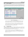
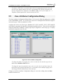
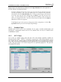
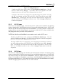
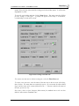
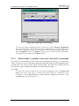
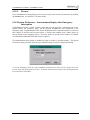
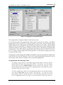
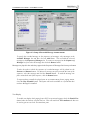
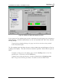
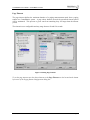
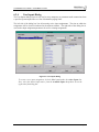
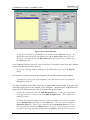
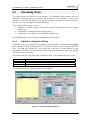
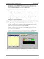
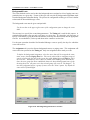
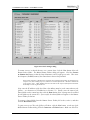
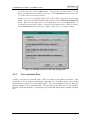
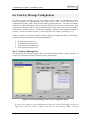
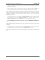
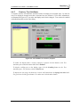
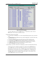
ControlMatrix User’s Guide - Getting Started
5. Using the standard Windows Telnet utility (see Windows Help) from the MediaMatrix,
check that you can connect to the MediaMatrix RATC by Telnetting into port 1632. The
standard login of “Defaultuser” with no password should return a welcome prompt from the
MediaMatrix. There should also be an indication in the MediaMatrix terminal window that a
connection has been made.
4.2
Making a ControlMatrix View File
4.2.1
Control Matrix View File Devices
It is intended that all of the ControlMatrix view file devices will be included in a future release of
MWare. When this occurs, this step will be unnecessary. Check the M-Ware Devices menu and
help system. If ControlMatrix devices are available, proceed to 4.2.2, if not continue with this
section.
The installation CD supplied with a ControlMatrix system includes a folder called \ControlMatrix
that contains all of the special devices required for a ControlMatrix View File. Before building a
ControlMatrix View File, this folder must be copied into the devices folder (most likely C:\Program
Files\MediaMatrix\MWare\Devices), thus creating a folder
C:\Program Files\MediaMatrix\MWare\Devices\ControlMatrix. There should be at least five
devices in this folder. When the MWare software is restarted, the devices will be available in the
device menu.
4.2.2
Building the View File
Once the ControlMatrix devices are available, a ControlMatrix View File can be created for use with
MediaMatrix. The remainder of this section assumes the reader is familiar with MediaMatrix.
In the ControlMatrix Device menu, there are devices called ‘nn zones’ (nn is the maximum number
of zones in a system). Choose the smallest device that will accommodate the number of output
paging zones required for the ControlMatrix system. This device is the core of the ControlMatrix
system. Place it on a new View File. It has a large number of input and output access points. The
inputs (on the left side of the block) are where input devices (such as paging stations, field inputs and
background sources) are connected. The outputs (on the right side of the block) are the outputs to
the paging zones.
Standard CobraNet I/O blocks may then be placed, corresponding to the DPU cards installed in the
MediaMatrix frame. Wire these I/O blocks as appropriate to the nn zones device. For a 50 Zone
device, on the input side, the top input corresponds with DAB Channel 101 in the Input
Configuration Dialog box (Setup utility) and the inputs follow sequentially. On the output side, the
first 40 outputs correspond to the first 10 zones. These are zones where SVC2s can be used and
allowance has been made for the four background outputs for each zone. From the top they are laid
out in sequence as follows:
Zone 1 Background 1
Zone 1 Background 2
Zone 1 Background 3
Zone 1 Background 4
Zone 2 Background 1
……
……
V4.0US, September 2004
Page 36