1
IBM ServeRAID
User’s Reference
IBM ServeRAID
User’s Reference
Note: Before using this information and the product it supports, be sure to read the general information in
Appendix E, “IBM Statement of Limited Warranty Z125-4753-0908/2006” on page 159 and Appendix
F, “Notices” on page 175.
Third Edition (August 2007)
© Copyright International Business Machines Corporation 2007. All rights reserved.
US Government Users Restricted Rights – Use, duplication or disclosure restricted by GSA ADP Schedule
Contract with IBM Corp.
Safety
Before installing this product, read the Safety Information.
Antes de instalar este produto, leia as Informações de Segurança.
Pred instalací tohoto produktu si prectete prírucku bezpecnostních instrukcí.
Læs sikkerhedsforskrifterne, før du installerer dette produkt.
Lees voordat u dit product installeert eerst de veiligheidsvoorschriften.
Ennen kuin asennat tämän tuotteen, lue turvaohjeet kohdasta Safety Information.
Avant d'installer ce produit, lisez les consignes de sécurité.
Vor der Installation dieses Produkts die Sicherheitshinweise lesen.
Prima di installare questo prodotto, leggere le Informazioni sulla Sicurezza.
Les sikkerhetsinformasjonen (Safety Information) før du installerer dette produktet.
Antes de instalar este produto, leia as Informações sobre Segurança.
© Copyright IBM Corp. 2007
iii
Antes de instalar este producto, lea la información de seguridad.
Läs säkerhetsinformationen innan du installerar den här produkten.
iv
IBM ServeRAID: User’s Reference
Statement 1:
DANGER
Electrical current from power, telephone, and communication cables is
hazardous.
To avoid a shock hazard:
• Do not connect or disconnect any cables or perform installation,
maintenance, or reconfiguration of this product during an electrical
storm.
• Connect all power cords to a properly wired and grounded electrical
outlet.
• Connect to properly wired outlets any equipment that will be attached
to this product.
• When possible, use one hand only to connect or disconnect signal
cables.
• Never turn on any equipment when there is evidence of fire, water, or
structural damage.
• Disconnect the attached power cords, telecommunications systems,
networks, and modems before you open the device covers, unless
instructed otherwise in the installation and configuration procedures.
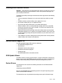
• Connect and disconnect cables as described in the following table
when installing, moving, or opening covers on this product or
attached devices.
To Connect:
To Disconnect:
1.
Turn everything OFF.
1.
Turn everything OFF.
2.
First, attach all cables to devices.
2.
First, remove power cords from outlet.
3.
Attach signal cables to connectors.
3.
Remove signal cables from connectors.
4.
Attach power cords to outlet.
4.
Remove all cables from devices.
5.
Turn device ON.
Safety
v
Statement 2:
CAUTION:
When replacing the lithium battery, use only IBM Part Number 13N2256 or an
equivalent type battery recommended by the manufacturer. If your system has a
module containing a lithium battery, replace it only with the same module type
made by the same manufacturer. The battery contains lithium and can explode if
not properly used, handled, or disposed of.
Do not:
•
Throw or immerse into water
•
Heat to more than 100°C (212°F)
•
Repair or disassemble
Dispose of the battery as required by local ordinances or regulations.
vi
IBM ServeRAID: User’s Reference
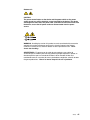
Statement 5:
CAUTION:
The power control button on the device and the power switch on the power
supply do not turn off the electrical current supplied to the device. The device
also might have more than one power cord. To remove all electrical current from
the device, ensure that all power cords are disconnected from the power
source.
2
1
WARNING: Handling the cord on this product or cords associated with accessories
sold with this product will expose you to lead, a chemical known to the State of
California to cause cancer, and birth defects or other reproductive harm. Wash
hands after handling.
ADVERTENCIA: El contacto con el cable de este producto o con cables de
accesorios que se venden junto con este producto, pueden exponerle al plomo, un
elemento químico que en el estado de California de los Estados Unidos está
considerado como un causante de cancer y de defectos congénitos, además de otros
riesgos reproductivos. Lávese las manos después de usar el producto.
Safety
vii
viii
IBM ServeRAID: User’s Reference
Contents
Safety . . . . . . . . . . . . . . . . . . . . . . . . . . . . . . . . . . . . . . . . . . . . . . . . . . . . . . . . . . . . iii
Preface. . . . . . . . . . . . . . . . . . . . . . . . . . . . . . . . . . . . . . . . . . . . . . . . . . . . . . . . . . . xiii
How this Book is Organized . . . . . . . . . . . . . . . . . . . . . . . . . . . . . . . . . . . . . . . . . . . xiii
Notices and Statements Used in this Book. . . . . . . . . . . . . . . . . . . . . . . . . . . . . . . xiv
Working Inside the Server with the Power on . . . . . . . . . . . . . . . . . . . . . . . . . . . . . xiv
Handling Static-Sensitive Devices . . . . . . . . . . . . . . . . . . . . . . . . . . . . . . . . . . . . . . xv
IBM ServeRAID Support CD . . . . . . . . . . . . . . . . . . . . . . . . . . . . . . . . . . . . . . . . . . xv
ROM Update Wizard . . . . . . . . . . . . . . . . . . . . . . . . . . . . . . . . . . . . . . . . . . . . . . xv
Device Drivers . . . . . . . . . . . . . . . . . . . . . . . . . . . . . . . . . . . . . . . . . . . . . . . . . . . xv
ARCCONF Command-Line Program . . . . . . . . . . . . . . . . . . . . . . . . . . . . . . . . . xvi
ACU/DOS Command-Line Program . . . . . . . . . . . . . . . . . . . . . . . . . . . . . . . . . . xvi
Diskette Images . . . . . . . . . . . . . . . . . . . . . . . . . . . . . . . . . . . . . . . . . . . . . . . . . xvi
ServeRAID Publications . . . . . . . . . . . . . . . . . . . . . . . . . . . . . . . . . . . . . . . . . . . xvi
IBM ServeRAID Applications CD . . . . . . . . . . . . . . . . . . . . . . . . . . . . . . . . . . . . . . xvi
ServeRAID Manager Program . . . . . . . . . . . . . . . . . . . . . . . . . . . . . . . . . . . . . . xvi
Supported Operating Systems . . . . . . . . . . . . . . . . . . . . . . . . . . . . . . . . . . . . . . . . xvii
Part 1. Installation and Configuration . . . . . . . . . . . . . . . . . . . . . . . . . . . . . . . . . . . . . . . . . . . . . 1
Chapter 1. Product Information . . . . . . . . . . . . . . . . . . . . . . . . . . . . . . . . . . . . . . . .
Option Package Contents . . . . . . . . . . . . . . . . . . . . . . . . . . . . . . . . . . . . . . . . . . . . . .
Controller Features . . . . . . . . . . . . . . . . . . . . . . . . . . . . . . . . . . . . . . . . . . . . . . . . . . .
ServeRAID-8i Controller . . . . . . . . . . . . . . . . . . . . . . . . . . . . . . . . . . . . . . . . . . . . . . .
ServeRAID-8k Controller . . . . . . . . . . . . . . . . . . . . . . . . . . . . . . . . . . . . . . . . . . . . . .
ServeRAID-8k-l Controller . . . . . . . . . . . . . . . . . . . . . . . . . . . . . . . . . . . . . . . . . . . . .
ServeRAID-8s Controller . . . . . . . . . . . . . . . . . . . . . . . . . . . . . . . . . . . . . . . . . . . . . .
© Copyright IBM Corp. 2007
3
3
4
5
6
7
8
Chapter 2. Installing a ServeRAID-8i, ServeRAID-8k, ServeRAID-8k-l, or
ServeRAID-8s Controller . . . . . . . . . . . . . . . . . . . . . . . . . . . . . . . . . . . . . . . . . . .
Installing the ServeRAID-8i Controller . . . . . . . . . . . . . . . . . . . . . . . . . . . . . . . . . . .
Installation Procedure. . . . . . . . . . . . . . . . . . . . . . . . . . . . . . . . . . . . . . . . . . . . . .
Installing the ServeRAID-8k Controller . . . . . . . . . . . . . . . . . . . . . . . . . . . . . . . . . . .
Installation Procedure. . . . . . . . . . . . . . . . . . . . . . . . . . . . . . . . . . . . . . . . . . . . . .
Installing the ServeRAID-8k-l Controller . . . . . . . . . . . . . . . . . . . . . . . . . . . . . . . . . .
Installation Procedure. . . . . . . . . . . . . . . . . . . . . . . . . . . . . . . . . . . . . . . . . . . . . .
Installing the ServeRAID-8s Controller . . . . . . . . . . . . . . . . . . . . . . . . . . . . . . . . . . .
Installation Procedure. . . . . . . . . . . . . . . . . . . . . . . . . . . . . . . . . . . . . . . . . . . . . .
Installing the Backup Battery for ServeRAID-8s. . . . . . . . . . . . . . . . . . . . . . . . . .
...............................................................
11
11
11
13
13
14
14
15
15
16
17
Chapter 3. RAID Technology Overview. . . . . . . . . . . . . . . . . . . . . . . . . . . . . . . . .
Stripe-Unit Size . . . . . . . . . . . . . . . . . . . . . . . . . . . . . . . . . . . . . . . . . . . . . . . . . . . . .
Selecting a RAID Level and Tuning Performance . . . . . . . . . . . . . . . . . . . . . . . . . . .
Supported RAID levels . . . . . . . . . . . . . . . . . . . . . . . . . . . . . . . . . . . . . . . . . . . . . . .
RAID Level-0 . . . . . . . . . . . . . . . . . . . . . . . . . . . . . . . . . . . . . . . . . . . . . . . . . . . .
RAID Level-1 . . . . . . . . . . . . . . . . . . . . . . . . . . . . . . . . . . . . . . . . . . . . . . . . . . . .
RAID Level-1 Enhanced . . . . . . . . . . . . . . . . . . . . . . . . . . . . . . . . . . . . . . . . . . . .
RAID Level-5 . . . . . . . . . . . . . . . . . . . . . . . . . . . . . . . . . . . . . . . . . . . . . . . . . . . .
RAID Level-5E Enhanced. . . . . . . . . . . . . . . . . . . . . . . . . . . . . . . . . . . . . . . . . . .
RAID Level-6 . . . . . . . . . . . . . . . . . . . . . . . . . . . . . . . . . . . . . . . . . . . . . . . . . . . .
RAID Level-x0. . . . . . . . . . . . . . . . . . . . . . . . . . . . . . . . . . . . . . . . . . . . . . . . . . . .
19
19
20
21
21
23
24
25
26
27
29
ix
Drive-State Descriptions. . . . . . . . . . . . . . . . . . . . . . . . . . . . . . . . . . . . . . . . . . . . . . 31
Physical-Drive-State Descriptions . . . . . . . . . . . . . . . . . . . . . . . . . . . . . . . . . . . . 31
Logical-Drive-State Descriptions . . . . . . . . . . . . . . . . . . . . . . . . . . . . . . . . . . . . . 32
Chapter 4. Configuring the ServeRAID-8i, ServeRAID-8k, ServeRAID-8k-l, or
ServeRAID-8s Controllers . . . . . . . . . . . . . . . . . . . . . . . . . . . . . . . . . . . . . . . . . .
Obtaining ServeRAID Updates. . . . . . . . . . . . . . . . . . . . . . . . . . . . . . . . . . . . . . . . .
Updating BIOS and Firmware Code . . . . . . . . . . . . . . . . . . . . . . . . . . . . . . . . . . . . .
Upgrading SAS/SATA HostRAID to the ServeRAID controller . . . . . . . . . . . . . . . . .
Upgrading ServeRAID-8e SAS/SATA HostRAID to a ServeRAID-8i
SAS controller . . . . . . . . . . . . . . . . . . . . . . . . . . . . . . . . . . . . . . . . . . . . . . . . . .
Configuring the ServeRAID Controller . . . . . . . . . . . . . . . . . . . . . . . . . . . . . . . . . . .
Using ServeRAID Manager . . . . . . . . . . . . . . . . . . . . . . . . . . . . . . . . . . . . . . . . .
Fine-Tuning your Configuration . . . . . . . . . . . . . . . . . . . . . . . . . . . . . . . . . . . . . .
Viewing your configuration . . . . . . . . . . . . . . . . . . . . . . . . . . . . . . . . . . . . . . . . . . . .
Getting Assistance . . . . . . . . . . . . . . . . . . . . . . . . . . . . . . . . . . . . . . . . . . . . . . . . . .
33
33
33
34
34
34
35
39
41
42
Chapter 5. Installing ServeRAID Device Drivers . . . . . . . . . . . . . . . . . . . . . . . . . 43
Part 2. Utility programs . . . . . . . . . . . . . . . . . . . . . . . . . . . . . . . . . . . . . . . . . . . . . . . . . . . . . . . . 45
x
Chapter 6. Using the ARC Utility. . . . . . . . . . . . . . . . . . . . . . . . . . . . . . . . . . . . . .
Using the Array Configuration Utility. . . . . . . . . . . . . . . . . . . . . . . . . . . . . . . . . . . . .
Managing Logical Drives . . . . . . . . . . . . . . . . . . . . . . . . . . . . . . . . . . . . . . . . . . .
Creating Logical Drives . . . . . . . . . . . . . . . . . . . . . . . . . . . . . . . . . . . . . . . . . . . .
Initializing Disk Drives . . . . . . . . . . . . . . . . . . . . . . . . . . . . . . . . . . . . . . . . . . . . .
Rescanning Disk Drives . . . . . . . . . . . . . . . . . . . . . . . . . . . . . . . . . . . . . . . . . . . .
Using Secure Erase . . . . . . . . . . . . . . . . . . . . . . . . . . . . . . . . . . . . . . . . . . . . . . .
Restoring a RAID . . . . . . . . . . . . . . . . . . . . . . . . . . . . . . . . . . . . . . . . . . . . . . . . .
Using SerialSelect . . . . . . . . . . . . . . . . . . . . . . . . . . . . . . . . . . . . . . . . . . . . . . . . . .
SerialSelect Options. . . . . . . . . . . . . . . . . . . . . . . . . . . . . . . . . . . . . . . . . . . . . . .
PHY Configuration Options . . . . . . . . . . . . . . . . . . . . . . . . . . . . . . . . . . . . . . . . .
Using the Disk Utilities . . . . . . . . . . . . . . . . . . . . . . . . . . . . . . . . . . . . . . . . . . . . . . .
Viewing the Event Log . . . . . . . . . . . . . . . . . . . . . . . . . . . . . . . . . . . . . . . . . . . . . . .
47
47
47
49
51
51
52
52
52
53
54
54
55
Chapter 7. Installing and Using the ARCCONF Command-Line Program . . . .
Installing the ARCCONF Command-Line Program . . . . . . . . . . . . . . . . . . . . . . . . .
Installing ARCCONF for Windows . . . . . . . . . . . . . . . . . . . . . . . . . . . . . . . . . . . .
Installing ARCCONF for NetWare . . . . . . . . . . . . . . . . . . . . . . . . . . . . . . . . . . . .
Installing ARCCONF for Red Hat Linux or SuSE Linux . . . . . . . . . . . . . . . . . . . .
Installing ARCCONF for OpenServer. . . . . . . . . . . . . . . . . . . . . . . . . . . . . . . . . .
Installing ARCCONF for UnixWare . . . . . . . . . . . . . . . . . . . . . . . . . . . . . . . . . . .
Installing ARCCONF for Solaris . . . . . . . . . . . . . . . . . . . . . . . . . . . . . . . . . . . . . .
Starting the ARCCONF Command-Line Program . . . . . . . . . . . . . . . . . . . . . . . . . .
Using the ARCCONF Command-Line Program . . . . . . . . . . . . . . . . . . . . . . . . . . . .
Using ARCCONF in Batch Mode . . . . . . . . . . . . . . . . . . . . . . . . . . . . . . . . . . . . .
ARCCONF Functions . . . . . . . . . . . . . . . . . . . . . . . . . . . . . . . . . . . . . . . . . . . . . . . .
Status functions . . . . . . . . . . . . . . . . . . . . . . . . . . . . . . . . . . . . . . . . . . . . . . . . . .
RAID configuration functions . . . . . . . . . . . . . . . . . . . . . . . . . . . . . . . . . . . . . . . .
57
57
57
57
58
59
60
60
61
61
61
62
62
62
IBM ServeRAID: User’s Reference
Chapter 8. Using the Array Configuration Utility for DOS . . . . . . . . . . . . . . . . .
Interactive Versus Script Mode . . . . . . . . . . . . . . . . . . . . . . . . . . . . . . . . . . . . . . . . .
Running the ACU . . . . . . . . . . . . . . . . . . . . . . . . . . . . . . . . . . . . . . . . . . . . . . . . .
Using Interactive Mode . . . . . . . . . . . . . . . . . . . . . . . . . . . . . . . . . . . . . . . . . . . . . . .
Creating a Logical Drive with ACU . . . . . . . . . . . . . . . . . . . . . . . . . . . . . . . . . . . .
Managing Logical Drives . . . . . . . . . . . . . . . . . . . . . . . . . . . . . . . . . . . . . . . . . . .
Using the Scripting Features. . . . . . . . . . . . . . . . . . . . . . . . . . . . . . . . . . . . . . . . . . .
Playback Mode . . . . . . . . . . . . . . . . . . . . . . . . . . . . . . . . . . . . . . . . . . . . . . . . . . .
Record Mode . . . . . . . . . . . . . . . . . . . . . . . . . . . . . . . . . . . . . . . . . . . . . . . . . . . .
Script File Syntax . . . . . . . . . . . . . . . . . . . . . . . . . . . . . . . . . . . . . . . . . . . . . . . . .
Error Handling . . . . . . . . . . . . . . . . . . . . . . . . . . . . . . . . . . . . . . . . . . . . . . . . . . .
Playback and Record Notes . . . . . . . . . . . . . . . . . . . . . . . . . . . . . . . . . . . . . . . . .
Invoking the ACU and using a script. . . . . . . . . . . . . . . . . . . . . . . . . . . . . . . . . . .
73
73
73
74
74
76
78
80
81
83
88
89
90
Chapter 9. Installing and Starting the ServeRAID Manager Program . . . . . . . .
Installing the ServeRAID Manager Program. . . . . . . . . . . . . . . . . . . . . . . . . . . . . . .
Installing ServeRAID Manager in Windows 2000 or Windows Server 2003 . . . .
Installing ServeRAID Manager in NetWare . . . . . . . . . . . . . . . . . . . . . . . . . . . . .
Installing ServeRAID Manager in Red Hat Linux or SuSE Linux . . . . . . . . . . . . .
Installing ServeRAID Manager in OpenServer . . . . . . . . . . . . . . . . . . . . . . . . . . .
Installing ServeRAID Manager in UnixWare. . . . . . . . . . . . . . . . . . . . . . . . . . . . .
Installing ServeRAID Manager in Solaris . . . . . . . . . . . . . . . . . . . . . . . . . . . . . . .
Installing ServeRAID Manager on VMWare . . . . . . . . . . . . . . . . . . . . . . . . . . . . .
Starting the ServeRAID Manager Program . . . . . . . . . . . . . . . . . . . . . . . . . . . . . . .
Starting the ServeRAID Manager program in Windows 2000 or
Windows Server 2003 . . . . . . . . . . . . . . . . . . . . . . . . . . . . . . . . . . . . . . . . . . . .
Starting the ServeRAID Manager Program in NetWare . . . . . . . . . . . . . . . . . . . .
Starting the ServeRAID Manager Program in Linux, OpenServer, and
UnixWare . . . . . . . . . . . . . . . . . . . . . . . . . . . . . . . . . . . . . . . . . . . . . . . . . . . . . .
Starting the ServeRAID Manager Program in Solaris . . . . . . . . . . . . . . . . . . . . .
91
91
91
93
93
94
95
95
96
96
96
97
97
98
Part 3. Maintenance and troubleshooting . . . . . . . . . . . . . . . . . . . . . . . . . . . . . . . . . . . . . . . . . 99
Chapter 10. Obtaining ServeRAID Updates . . . . . . . . . . . . . . . . . . . . . . . . . . . . 101
Downloadable files from the World Wide Web . . . . . . . . . . . . . . . . . . . . . . . . . . . . 101
Chapter 11. Solving ServeRAID Problems . . . . . . . . . . . . . . . . . . . . . . . . . . . . .
IBM ServeRAID Support CD Warning Message While Starting . . . . . . . . . . . . . . .
ServeRAID Controller Messages . . . . . . . . . . . . . . . . . . . . . . . . . . . . . . . . . . . . . .
General Problems . . . . . . . . . . . . . . . . . . . . . . . . . . . . . . . . . . . . . . . . . . . . . . . . . .
Operating System Problems . . . . . . . . . . . . . . . . . . . . . . . . . . . . . . . . . . . . . . . . . .
Recovering from Problems Starting the ServeRAID Manager . . . . . . . . . . . . . . . .
Recovering from an Incomplete Format of a Physical Drive . . . . . . . . . . . . . . . . . .
Rebuilding a Defunct Drive . . . . . . . . . . . . . . . . . . . . . . . . . . . . . . . . . . . . . . . . . . .
Recovering from Defunct Drives. . . . . . . . . . . . . . . . . . . . . . . . . . . . . . . . . . . . .
Rebuilding a Hot-Swap Drive . . . . . . . . . . . . . . . . . . . . . . . . . . . . . . . . . . . . . . .
Restoring a Logical Drive Configuration . . . . . . . . . . . . . . . . . . . . . . . . . . . . . . .
Recovering from Multiple Physical Drive Failures (Windows only) . . . . . . . . . . . . .
Capturing the ServeRAID Logs . . . . . . . . . . . . . . . . . . . . . . . . . . . . . . . . . . . . .
Checking the Hardware Connections . . . . . . . . . . . . . . . . . . . . . . . . . . . . . . . . .
Forcing the Logical Drive into the Okay State . . . . . . . . . . . . . . . . . . . . . . . . . .
Troubleshooting. . . . . . . . . . . . . . . . . . . . . . . . . . . . . . . . . . . . . . . . . . . . . . . . . . . .
103
103
103
104
105
106
108
108
108
109
110
110
111
111
111
112
Contents
xi
Chapter 12. Getting Help and Technical Assistance. . . . . . . . . . . . . . . . . . . . .
Before You Call . . . . . . . . . . . . . . . . . . . . . . . . . . . . . . . . . . . . . . . . . . . . . . . . . . . .
Using the Documentation . . . . . . . . . . . . . . . . . . . . . . . . . . . . . . . . . . . . . . . . . . . .
Getting Help and Information from the World Wide Web . . . . . . . . . . . . . . . . . . . .
Software Service and Support . . . . . . . . . . . . . . . . . . . . . . . . . . . . . . . . . . . . . . . .
Hardware Service and Support . . . . . . . . . . . . . . . . . . . . . . . . . . . . . . . . . . . . . . .
113
113
113
113
114
114
Part 4. Appendixes. . . . . . . . . . . . . . . . . . . . . . . . . . . . . . . . . . . . . . . . . . . . . . . . . . . . . . . . . . . 115
Appendix A. Creating ServeRAID Diskettes . . . . . . . . . . . . . . . . . . . . . . . . . . .
Diskette Images for ServeRAID SAS Controllers . . . . . . . . . . . . . . . . . . . . . . . . . .
Creating Diskettes on Windows . . . . . . . . . . . . . . . . . . . . . . . . . . . . . . . . . . . . . . .
Creating Diskettes on Linux or UNIX . . . . . . . . . . . . . . . . . . . . . . . . . . . . . . . . . . .
117
117
117
117
Appendix B. Creating a Windows PE CD . . . . . . . . . . . . . . . . . . . . . . . . . . . . . . 119
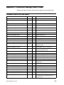
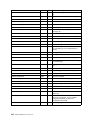
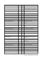
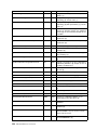
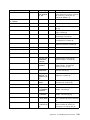
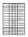
Appendix C. ServeRAID Manager Event Codes . . . . . . . . . . . . . . . . . . . . . . . . 121
Common Events (GUI and Agent) . . . . . . . . . . . . . . . . . . . . . . . . . . . . . . . . . . . . . 121
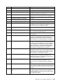
Native ARC Events . . . . . . . . . . . . . . . . . . . . . . . . . . . . . . . . . . . . . . . . . . . . . . . . . 136
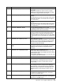
Appendix D. Event Logging and Blink Codes . . . . . . . . . . . . . . . . . . . . . . . . . . 147
Appendix E. IBM Statement of Limited Warranty Z125-4753-0908/2006 . . . . . 159
Appendix F. Notices . . . . . . . . . . . . . . . . . . . . . . . . . . . . . . . . . . . . . . . . . . . . . . . 175
Glossary . . . . . . . . . . . . . . . . . . . . . . . . . . . . . . . . . . . . . . . . . . . . . . . . . . . . . . . . 183
Index . . . . . . . . . . . . . . . . . . . . . . . . . . . . . . . . . . . . . . . . . . . . . . . . . . . . . . . . . . . 187
xii
IBM ServeRAID: User’s Reference
Preface
This book provides information for configuring the IBM® ServeRAID™-8i,
ServeRAID-8k, ServeRAID-8k-l, and ServeRAID-8s controllers, installing device
drivers, and installing and using the ServeRAID utility programs.
How this Book is Organized
Chapter 1, “Product Information” on page 3 contains introductory information and
specifications for the IBM ServeRAID-8i, ServeRAID-8k, ServeRAID-8k-l, and
ServeRAID-8s controllers.
Chapter 2, “Installing a ServeRAID-8i, ServeRAID-8k, ServeRAID-8k-l, or ServeRAID8s Controller” on page 11 explains how to install and cable the ServeRAID-8i,
ServeRAID-8k, ServeRAID-8k-l, and ServeRAID-8s controllers.
Chapter 3, “RAID Technology Overview” on page 19 contains general information
about RAID technology.
Chapter 4, “Configuring the ServeRAID-8i, ServeRAID-8k, ServeRAID-8k-l, or
ServeRAID-8s Controllers” on page 33 explains the ServeRAID configuration process.
You can refer to the information when configuring one or more devices attached to a
ServeRAID controller.
Chapter 5, “Installing ServeRAID Device Drivers” on page 43 contains information
about installing and updating the ServeRAID device drivers.
Chapter 6. “Using the ARC Utility” on page 47, Chapter 7. “Installing and Using the
ARCCONF Command-Line Program” on page 57, and Chapter 8. “Using the Array
Configuration Utility for DOS” on page 73 contain instructions for installing, starting,
and using the ARC, ARCCONF, and ACU programs. You can use these operatingsystem-specific programs to maintain and monitor your ServeRAID subsystem.
Chapter 9, “Installing and Starting the ServeRAID Manager Program” on page 91
contains instructions for installing and starting the ServeRAID Manager program. You
can use this program to maintain and monitor your ServeRAID subsystem.
Chapter 10, “Obtaining ServeRAID Updates” on page 101 provides information for
obtaining IBM ServeRAID updates from the World Wide Web.
Chapter 11, “Solving ServeRAID Problems” on page 103 describes the ServeRAID
POST error codes and startup messages. This chapter also includes some basic
information about rebuilding a defunct drive and troubleshooting failover and cluster
problems.
Chapter 12, “Getting Help and Technical Assistance” on page 113 provides
information about accessing the IBM World Wide Web sites to obtain future code and
information updates for the ServeRAID controller.
Appendix A, “Creating ServeRAID Diskettes” on page 117 contains instructions for
creating device driver installation diskettes, which contain device drivers and the
command-line utility programs.
Appendix B. “Creating a Windows PE CD” on page 119 contains instructions for
creating a WinPD build image on your hard drive, integrating drivers into the WinPE
image, and creating a CD of the customized image.
© Copyright IBM Corp. 2007
xiii
Appendix C. “ServeRAID Manager Event Codes” on page 121 contains tables
describing ServeRAID Manager common and native ARC events.
Appendix D. “Event Logging and Blink Codes” on page 147 contains a table
describing the Event Logging and Blink Codes.
Appendix E, “IBM Statement of Limited Warranty Z125-4753-0908/2006” on page 159
contains warranty information.
Appendix F, “Notices” on page 175 contains product notices and trademarks.
Notices and Statements Used in this Book
The caution and danger statements that appear in this book are also in the
multilingual Safety Information Book, which is on the IBM Documentation CD. Each
statement is numbered for reference to the corresponding statement in the Safety
Information Book.
The following types of notices and statements are used in this book:
•
Note: These notices provide important tips, guidance, or advice.
•
Important: These notices provide information or advice that might help you avoid
inconvenient or problem situations.
•
Attention: These notices indicate possible damage to programs, devices, or data.
An attention notice is placed just before the instruction or situation in which
damage could occur.
•
Caution: These statements indicate situations that can be potentially hazardous
to you. A caution statement is placed just before the description of a potentially
hazardous procedure step or situation.
•
Danger: These statements indicate situations that can be potentially lethal or
extremely hazardous to you. A danger statement is placed just before the
description of a potentially lethal or extremely hazardous procedure step or
situation.
Working Inside the Server with the Power on
Your server supports hot-plug, hot-add, and hot-swap devices and is designed to
operate safely while turned on with the cover removed. Follow these guidelines when
you work inside a server that is turned on:
xiv
•
Avoid loose-fitting clothing on your forearms. Button long-sleeved shirts before
working inside the server; do not wear cuff links while working inside the server.
•
Do not allow your necktie or scarf to hang inside the server.
•
Remove jewelry, such as bracelets, necklaces, rings, and loose-fitting wrist
watches.
•
Remove items from your shirt pocket (such as pens or pencils) that could fall into
the server as you lean over it.
•
Avoid dropping any metallic objects, such as paper clips, hair pins, or screws, into
the server.
IBM ServeRAID: User’s Reference
Handling Static-Sensitive Devices
Attention: Static electricity can damage electronic devices, including your server. To
avoid damage, keep static-sensitive devices in their static-protective packages until
you are ready to install them.
To reduce the possibility of damage from electrostatic discharge, observe the following
precautions:
•
Limit your movement. Movement can cause static electricity to build up around
you.
•
Handle the device carefully, holding it by its edges or its frame.
•
Do not touch solder joints, pins, or exposed circuitry.
•
Do not leave the device where others can handle and damage it.
•
While the device is still in its static-protective package, touch it to an unpainted
metal part of the server for at least 2 seconds. This drains static electricity from
the package and from your body.
•
Remove the device from its package and install it directly into the server without
setting down the device. If it is necessary to set down the device, place it back into
its static-protective package. Do not place the device on your server cover or on a
metal surface.
•
Take additional care when handling devices during cold weather. Heating reduces
indoor humidity and increases static electricity.
IBM ServeRAID Support CD
The IBM ServeRAID Support CD contains the following:
•
ServeRAID ROM Update wizard
•
Device drivers
•
ARCCONF command-line program
•
ACU/DOS command-line program
•
Diskette images
•
ServeRAID publications and readme text files
ROM Update Wizard
The ROM (read-only memory) Update wizard is a program designed to automatically
identify and scan each ServeRAID controller installed in your server. If the BIOS and
firmware code need updating, the wizard will give you the opportunity to do so.
Device Drivers
The device drivers are located in the following directories on the IBM ServeRAID
Support CD:
e:/operatingsystem/sas/DRIVER
where e is the CD-ROM drive and operatingsystem is the specific operating system
used in the ServeRAID installation.
The device drivers are also provided on operating-system-specific diskette images.
Preface
xv
ARCCONF Command-Line Program
Use this program to configure and manage your ServeRAID-8i, ServeRAID-8k,
ServeRAID-8k-l, and ServeRAID-8s Serial-Attached SCSI (SAS) controllers on the
supported operating systems. This program is available on the IBM ServeRAID
Support CD.
ACU/DOS Command-Line Program
Use this program to configure and manage your ServeRAID-8i, ServeRAID-8k,
ServeRAID-8k-l, and ServeRAID-8s SAS controllers using MS DOS. This program is
available on the IBM ServeRAID Support CD.
Diskette Images
Device driver diskette images are available in the /DISKETTE/SAS directory on the
IBM ServeRAID Support CD.
For a complete list of diskette images and instructions for creating the diskettes, see
Appendix A, “Creating ServeRAID Diskettes” on page 117.
ServeRAID Publications
The following books are available in Portable Document Format (PDF) on the IBM
ServeRAID Support CD in the BOOKS directory:
•
IBM ServeRAID User’s Reference (SRAID.PDF)
•
IBM Installation Guide: ServeRAID-8i, ServeRAID-8k, ServeRAID-8k-l SAS, and
ServeRAID-8s Controllers (INSTALL.PDF)
Note: Use Adobe Acrobat Reader to view these files.
IBM ServeRAID Applications CD
The IBM ServeRAID Applications CD contains the ServeRAID Manager program.
ServeRAID Manager Program
Use this program to configure logical drives on ServeRAID controllers. ServeRAID
Manager operates in two ways: in bootable-CD mode and as an installed program. In
bootable-CD mode, you can configure your ServeRAID adapter before you install an
operating system.
This program is available in the following directory on the IBM ServeRAID Applications
CD:
e:/operatingsystem/MANAGER
where e is the CD-ROM drive and operatingsystem is the specific operating system
used in the ServeRAID installation.
xvi
IBM ServeRAID: User’s Reference
Supported Operating Systems
The following operating systems are supported with ServeRAID-8i, ServeRAID-8k,
ServeRAID-8k-l, ServeRAID-8s controllers:
•
Microsoft Windows 2000 Server and Advanced Server
•
Microsoft Windows Server 2003 Standard Edition and Enterprise Edition
•
Microsoft Windows Server 2003 for EM64T
•
Microsoft Windows PE
•
Novell NetWare 6.5
•
Red Hat Enterprise Linux 3 AS/ES/WS for 32-bit kernels
•
Red Hat Enterprise Linux 3 AS/ES for EM64T 64-bit kernels
•
Red Hat Enterprise Linux 4 AS/ES/WS for 32-bit kernels
•
Red Hat Enterprise Linux 4 AS/ES for EM64T 64-bit kernels
•
Red Hat Enterprise Linux 5 AS/ES for 32-bit kernels
•
Red Hat Enterprise Linux 5 AS/ES for EM64T 64-bit kernels
•
SuSE Linux Enterprise Server 9 for 32-bit kernels
•
SuSE Linux Enterprise Server 9 for EM64T kernels
•
SuSE Linux Enterprise Server 10 for 32-bit kernels
•
SuSE Linux Enterprise Server 10 for EM64T kernels
•
SuSE Linux Standard Desktop 9.0 (ServeRAID-8s only)
•
SCO OpenServer 5.0.7
•
SCO OpenServer 6.0
•
SCO UnixWare 7.1.3
•
SCO UnixWare 7.1.4
•
Sun Solaris 10
Preface
xvii
xviii
IBM ServeRAID: User’s Reference
Part 1. Installation and Configuration
© Copyright IBM Corp. 2007
1
2
IBM ServeRAID: User’s Reference
Chapter 1. Product Information
This book provides information needed to install and configure the IBM ServeRAID-8i
Serial-Attached SCSI (SAS) Controller (Part Number 13N2227 and 39R8729),
ServeRAID-8k SAS Controller (Part Number 25R8064), ServeRAID-8k-l SAS
Controller (standard on many systems), and ServeRAID-8s SAS Controller (Part
Number 39R8812).
These high-performance, redundant array of independent disk (RAID) controllers are
ideally suited for data-storage environments that require superior performance,
flexibility, and reliable data storage. (See “Controller Features” for more information.)
Option Package Contents
The ServeRAID option package contains:
•
IBM ServeRAID Support CD
See “IBM ServeRAID Support CD” on page xv for more detailed information.
•
IBM ServeRAID Applications CD
See “IBM ServeRAID Applications CD” on page xvi for more detailed information.
•
IBM Installation Guide: ServeRAID-8i, ServeRAID-8k, ServeRAID-8k-l, and
ServeRAID-8s SAS Controllers
Contains instructions for installing the ServeRAID-8i, ServeRAID-8k,
ServeRAID-8k-l, and ServeRAID-8s controllers and device drivers.
•
IBM ServeRAID-8i, ServeRAID-8k, ServeRAID-8k-l, or ServeRAID-8s SAS
controller
Attention: Do not open the static-protective package containing the controller
until you are instructed to do so.
Contact your place of purchase if any items are missing or damaged.
© Copyright IBM Corp. 2007
3
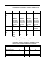
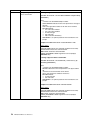
Controller Features
The standard features of the ServeRAID-8i, ServeRAID-8k, ServeRAID-8k-l, and
ServeRAID-8s controllers are:
Feature
ServeRAID-8i
ServeRAID-8k
ServeRAID-8k-l
ServeRAID-8s
Battery-backup cache Yes
Yes
No
Yes (optional)
Cache memory
256 MB
256 MB
32 MB (no I/O cache)
256 MB
Hard disk drives
(max.)
64
64
64
128
Logical drives (max.)
24
24
24
24
Note: While the
ServeRAID-8i can
support 24 logical
drives, it can only
support 10 logical
drives per physical
drive. You will need 3
physical drives to
create 24 logical
drives.
Note: While the
ServeRAID-8k can
support 24 logical
drives, it can only
support 10 logical
drives per physical
drive. You will need 3
physical drives to
create 24 logical
drives.
Note: While the
ServeRAID-8k-l can
support 24 logical
drives, it can only
support 10 logical
drives per physical
drive. You will need 3
physical drives to
create 24 logical
drives.
Note: While the
ServeRAID-8s can
support 24 logical
drives, it can only
support 10 logical
drives per physical
drive. You will need 3
physical drives to
create 24 logical
drives.
Microprocessor
Intel IOP321 600MHz
n/a
n/a
Intel IOP333 800MHz
Channels/Ports
0
0
0
2 (second internal
port not used)
Transfer speed (max.)
3 Gbps
3 Gbps
3 Gbps
3 Gbps
Supported RAID
levels
0, 1, 1E, 5, 5EE, 6,
10, 50, 60
0, 1, 1E, 5, 6, 10
0, 1, 10
0, 1, 1E, 5, 6, 10, 50
Interface bus
PCIx: 64 bit at 66 to
133 MHz
DDR2: 64 bit at 533
MHz
DDR2: 64 bit at 533
MHz
PCIe x8 at 2.5 Gbps
Notes:
1. See Chapter 3, “RAID Technology Overview” on page 19 for additional information
about logical drives and RAID levels.
2. The number of logical drives varies according to the firmware level and stripe-unit
size.
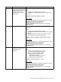
The ServeRAID-8i, ServeRAID-8k, ServeRAID-8k-l, and ServeRAID-8s controllers
support the following features of ServeRAID software and utility programs.
ServeRAID features
ServeRAID-8i
ServeRAID-8k
ServeRAID-8k-l
ServeRAID-8s
ServeRAID ROM Update wizard
Yes
Yes
Yes
Yes
ServeRAID Manager
Yes
Yes
Yes
Yes
BIOS Configuration program
Yes
Yes
Yes
Yes
Command-Line Tool
Yes
Yes
Yes
Yes
ARCCONF FlashCopy™ function
Yes
Yes
No
Yes
Copy Back
Yes
Yes
Yes
Yes
Clustering
No
No
No
No
Failover
No
No
No
No
4
IBM ServeRAID: User’s Reference
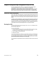
The ServeRAID-8i, ServeRAID-8k, ServeRAID-8k-l, and ServeRAID-8s controllers
support the following Logical Drive Migrations (LDMs).
Logical Drive Migration
ServeRAID-8i
ServeRAID-8k
ServeRAID-8k-l
ServeRAID-8s
Simple Volume > 1
X
X
X
1>0
X
X
X
0 < > 10
X
X
X
0<>5
X
X
X
1>5
X
X
X
5 < > 5EE
X
5<>6
X
X
X
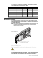
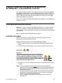
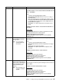
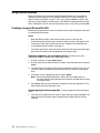
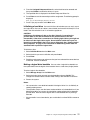
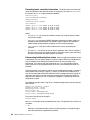
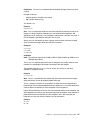
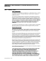
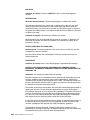
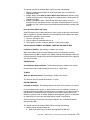
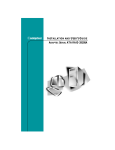
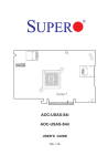
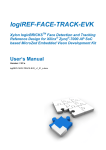
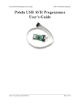
ServeRAID-8i Controller
The ServeRAID-8i controller is a Serial-Attached SCSI (SAS) controller that has no
independent SCSI channels. It must be used with an IBM xSeries server that contains
an integrated SAS controller.
Note: In the event of a power outage or failure, the battery-backup cache protects the
data stored in the ServeRAID cache memory when using the write-back
setting of the write-cache mode.
Battery for Backup Cache
Note: It is recommended that you replace
the battery every two (2) years.
Figure 1. ServeRAID-8i controller
Note: The ServeRAID-8i controller uses the module containing a lithium battery.
WARNING:
The battery ships from the factory 30% charged. It takes 4 to 6 hours to initially
charge the battery cell. The controller’s cache will be set by the firmware to
Chapter 1. Product Information
5
write-through mode until the battery is charged to an acceptable level. The user
can set the cache mode manually using ACU or ServeRAID Manager, after the
battery has initially been charged.
Statement 2:
CAUTION:
When replacing the lithium battery, use only IBM Part Number 25R8118 or an
equivalent type battery recommended by the manufacturer. If your system has a
module containing a lithium battery, replace it only with the same module type
made by the same manufacturer. The battery contains lithium and can explode if
not properly used, handled, or disposed of.
Do not:
•
Throw or immerse into water
•
Heat to more than 100°C (212°F)
•
Repair or disassemble
Dispose of the battery as required by local ordinances or regulations.
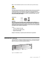
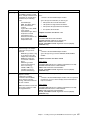
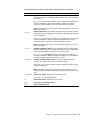
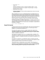
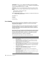
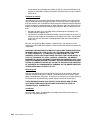
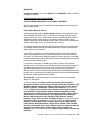
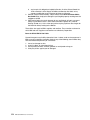
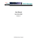
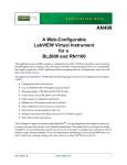
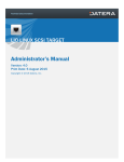
ServeRAID-8k Controller
The ServeRAID-8k controller is a Serial-Attached SCSI (SAS) device with a 256
megabye unbuffered DIMM that connects directly to specific IBM planar designs to
provide full RAID capabilities. It is capable of supporting up to three (3) EXP3000
external enclosures (for more information, see the user documentation that comes
with the EXP3000 enclosure).
The ServeRAID-8k comes with a battery-backup cache that connects to the server
chassis.
Note: In the event of a power outage or failure, the battery-backup cache protects the
data stored in the ServeRAID cache memory when using the write-back
setting of the write-cache mode.
Note: It is recommended that you replace
the battery every two (2) years.
Figure 2. ServeRAID-8k controller and backup battery
6
IBM ServeRAID: User’s Reference
Note: The ServeRAID-8k controller uses the module containing a lithium battery.
WARNING:
The battery ships from the factory 30% charged. It takes 4 to 6 hours to initially
charge the battery cell. The controller’s cache will be set by the firmware to
write-through mode until the battery is charged to an acceptable level. The user
can set the cache mode manually using ACU or ServeRAID Manager, after the
battery has initially been charged.
Statement 2:
CAUTION:
When replacing the lithium battery, use only IBM Part Number 25R8088 or an
equivalent type battery recommended by the manufacturer. If your system has a
module containing a lithium battery, replace it only with the same module type
made by the same manufacturer. The battery contains lithium and can explode if
not properly used, handled, or disposed of.
Do not:
•
Throw or immerse into water
•
Heat to more than 100°C (212°F)
•
Repair or disassemble
Dispose of the battery as required by local ordinances or regulations.
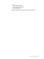
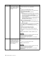
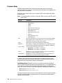
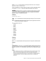
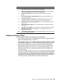
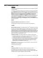
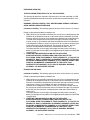
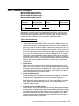
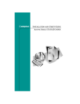
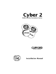
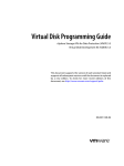
ServeRAID-8k-l Controller
The ServeRAID-8k-l controller (standard on many systems) is a Serial-Attached SCSI
(SAS) device with a 32 megabyte unbuffered DIMM that connects directly to specific
IBM planar designs to provide limited RAID capabilities.
Figure 3. ServeRAID-8k-l controller
Chapter 1. Product Information
7
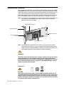
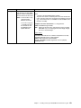
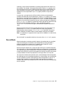
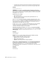
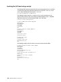
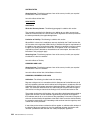
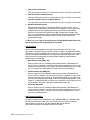
ServeRAID-8s Controller
The ServeRAID-8s controller is a Serial-Attached SCSI (SAS) controller with 256 MB
DDR2 DIMM, one internal SAS connector to support either direct connection to SAS
or SATA disk drives or connection to a backplane (the second internal connector is not
used), and one external mini-SAS connector to support up to three (3) EXP3000
expansion enclosures (for more information, see the user documentation that comes
with the EXP3000 enclosure). A battery-backup module is available as an option.
Note: In the event of a power outage or failure, the battery-backup cache protects the
data stored in the ServeRAID cache memory when using the write-back
setting of the write-cache mode.
Internal SAS connector
Mounting bracket
Battery connector
External mini-SAS
connector
Not currently used
Note: The ServeRAID-8s controller has the option for a backup battery module
containing a lithium battery. (The part number for the optional backup battery
module is IBM Part Number 39R8765. However, if you replace the battery, you
should order replacement battery IBM Part Number 13N2256.)
WARNING:
The battery ships from the factory 30% charged. It takes 4 to 6 hours to initially
charge the battery cell. The controller’s cache will be set by the firmware to
write-through mode until the battery is charged to an acceptable level. The user
can set the cache mode manually using ACU or ServeRAID Manager, after the
battery has initially been charged.
Statement 2:
CAUTION:
When replacing the lithium battery, use only IBM Part Number 25R8118 or an
equivalent type battery recommended by the manufacturer. If your system has a
module containing a lithium battery, replace it only with the same module type
made by the same manufacturer. The battery contains lithium and can explode if
not properly used, handled, or disposed of.
8
IBM ServeRAID: User’s Reference
Do not:
•
Throw or immerse into water
•
Heat to more than 100°C (212°F)
•
Repair or disassemble
Dispose of the battery as required by local ordinances or regulations.
Chapter 1. Product Information
9
10
IBM ServeRAID: User’s Reference
Chapter 2. Installing a ServeRAID-8i, ServeRAID-8k,
ServeRAID-8k-l, or ServeRAID-8s Controller
This chapter provides installation and cabling instructions for the IBM ServeRAID-8i,
ServeRAID-8k, ServeRAID-8k-l, and ServeRAID-8s controllers. Before you install a
ServeRAID controller in your server, review and follow the instructions in “Safety” on
page iii, “Working Inside the Server with the Power on” on page xiv, and “Handling
Static-Sensitive Devices” on page xv.
You can install one ServeRAID-8i, ServeRAID-8k, ServeRAID-8k-l, or ServeRAID-8s
controller in a server.
Installing the ServeRAID-8i Controller
Attention: If you plan to install a ServeRAID-8i controller in a server that contains
data, back up the data first. When the ServeRAID-8i controller is installed, you will
lose access to any data or applications on physical drives connected to the integrated
SAS controller.
Review “Handling Static-Sensitive Devices” on page xv.
Installation Procedure
During the installation, you might need a small, flat-blade screwdriver and the
documentation that comes with your server.
Complete the following steps to install the ServeRAID-8i controller:
1. Review “Safety” on page iii and the Safety Information Book provided with your
server.
2. Turn off the server and disconnect all power cords and cables from the server.
Statement 5:
CAUTION:
The power control button on the device and the power
switch on the power supply do not turn off the electrical
current supplied to the device. The device also might
have more than one power cord. To remove all electrical
current from the device, ensure that all power cords are 2
1
disconnected from the power source.
3. Remove the server cover and locate the correct PCI expansion slot for the SAS
controller.
Notes: a.The ServeRAID-8i controller must be installed in the extended PCI
expansion slot. If you have not already done so, see the documentation that
comes with your server to determine the correct PCI expansion slot for the
ServeRAID-8i controller.
b. If another controller is already installed in the extended PCI expansion slot
designed for the ServeRAID-8i controller, you must remove the controller
before installing the ServeRAID-8i controller.
c. You may need to remove one of the slot dividers in order to access the
expansion slot.
© Copyright IBM Corp. 2007
11
4. Touch the static-protective package containing the controller to an unpainted
metal part of the server for at least 2 seconds. This discharges any static
electricity from the package and your body.
5. Holding the controller by the edges, remove it from the static-protective package.
Do not touch any exposed components on the controller.
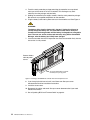
6. Plug the battery cable into its power source on the controller card. See Figure 4.
WARNING:
The battery ships from the factory 30% charged. It takes 4 to 6 hours to
initially charge the battery cell. The controller’s cache will be set by the
firmware to write-through mode until the battery is charged to an acceptable
level. The user can set the cache mode manually using ACU or ServeRAID
Manager, after the battery has initially been charged.
7. Insert the controller into the PCI expansion slot. Press the controller firmly into the
slot so that it is fully seated.
Connect battery
cable to power
source
Note: It is recommended that you replace
the battery every two (2) years.
Figure 4. Inserting a ServeRAID-8i controller into the PCI expansion slot
8. If you have physical drives to install, install them now. See your server
documentation for drive installation instructions.
9. Install the server cover.
10. Reconnect the cables and cords. See your server documentation if you need
detailed instructions.
11. Go to “Updating BIOS and Firmware Code” on page 33.
12
IBM ServeRAID: User’s Reference
Installing the ServeRAID-8k Controller
Attention: If you plan to install a ServeRAID-8k controller in a server that contains
data, back up the data first. When the ServeRAID-8k controller is installed, you will
lose access to any data or applications on physical drives connected to the integrated
SAS controller. Review “Handling Static-Sensitive Devices” on page xv.
Installation Procedure
During the installation, you might need a small, flat-blade screwdriver and the
documentation that comes with your server.
Complete the following steps to install the ServeRAID-8k controller:
1. Review “Safety” on page iii and the Safety Information Book provided with your
server.
2. Turn off the server and disconnect all power cords and cables from the server.
Statement 5:
CAUTION:
The power control button on the device and the power
switch on the power supply do not turn off the electrical
current supplied to the device. The device also might
have more than one power cord. To remove all electrical
2
current from the device, ensure that all power cords are
1
disconnected from the power source.
3. Remove the server cover and locate the memory slot on the motherboard.
4. Touch the static-protective package containing the controller to an unpainted
metal part of the server for at least 2 seconds. This discharges any static
electricity from the package and your body.
5. Holding the controller by the edges, remove it from the static-protective package.
Do not touch any exposed components on the controller.
6. Insert the controller into the memory slot. Press the controller firmly into the slot
so that it is fully seated.
7. Place and connect the backup battery (see your server documentation for battery
installation instructions).
Note: It is recommended that the battery be replaced every two years.
WARNING:
The battery ships from the factory 30% charged. It takes 4 to 6 hours to
initially charge the battery cell. The controller’s cache will be set by the
firmware to write-through mode until the battery is charged to an acceptable
level. The user can set the cache mode manually using ACU or ServeRAID
Manager, after the battery has initially been charged.
8. Replace the server cover.
9. Reconnect the cables and cords. See your server documentation if you need
detailed instructions.
10. Go to “Updating BIOS and Firmware Code” on page 33.
Chapter 2. Installing a ServeRAID-8i, ServeRAID-8k, ServeRAID-8k-l, or ServeRAID-8s Controller
13
Installing the ServeRAID-8k-l Controller
Attention: If you plan to install a ServeRAID-8k-l controller in a server that contains
data, back up the data first. When the ServeRAID-8k-l controller is installed, you will
lose access to any data or applications on physical drives connected to the integrated
SAS controller.
Review “Handling Static-Sensitive Devices” on page xv.
Installation Procedure
During the installation, you might need a small, flat-blade screwdriver and the
documentation that comes with your server.
Complete the following steps to install the ServeRAID-8k-l controller:
1. Review “Safety” on page iii and the Safety Information Book provided with your
server.
2. Turn off the server and disconnect all power cords and cables from the server.
Statement 5:
CAUTION:
The power control button on the device and the power
switch on the power supply do not turn off the electrical
current supplied to the device. The device also might
have more than one power cord. To remove all electrical 2
current from the device, ensure that all power cords are
1
disconnected from the power source.
3. Remove the server cover and locate the memory slot on the motherboard.
4. Touch the static-protective package containing the controller to an unpainted
metal part of the server for at least 2 seconds. This discharges any static
electricity from the package and your body.
5. Holding the controller by the edges, remove it from the static-protective package.
Do not touch any exposed components on the controller.
6. Insert the controller into the memory slot. Press the controller firmly into the slot
so that it is fully seated.
7. Replace the server cover.
8. Reconnect the cables and cords. See your server documentation if you need
detailed instructions.
9. Go to “Updating BIOS and Firmware Code” on page 33.
14
IBM ServeRAID: User’s Reference
Installing the ServeRAID-8s Controller
Attention: If you plan to install a ServeRAID-8s controller in a server that contains
data, back up the data first. When the ServeRAID-8s controller is installed, you will
lose access to any data or applications on physical drives connected to the integrated
SAS controller.
Review “Handling Static-Sensitive Devices” on page xv.
Installation Procedure
During the installation, you might need a small, flat-blade screwdriver and the
documentation that comes with your server.
Complete the following steps to install the ServeRAID-8s controller:
1. Review “Safety” on page iii and the Safety Information Book provided with your
server.
2. Turn off the server and disconnect all power cords and cables from the server.
Statement 5:
CAUTION:
The power control button on the device and the power
switch on the power supply do not turn off the electrical
current supplied to the device. The device also might
have more than one power cord. To remove all electrical 2
current from the device, ensure that all power cords are
1
disconnected from the power source.
3. Remove the server cover and locate the PCIe x8 slot.
4. Remove the expansion slot cover, if applicable.
5. Touch the static-protective package containing the controller to an unpainted
metal part of the server for at least 2 seconds. This discharges any static
electricity from the package and your body.
6. Holding the controller by the edges, remove it from the static-protective package.
Do not touch any exposed components on the controller.
7. If you are installing a backup battery, place and connect it now (see “Installing the
Backup Battery for ServeRAID-8s” on page 16 for battery installation instructions).
Note:It is recommended that the battery be replaced every two years.
WARNING:
The battery ships from the factory 30% charged. It takes 4 to 6 hours
to initially charge the battery cell. The controller’s cache will be set by
the firmware to write-through mode until the battery is charged to an
acceptable level. The user can set the cache mode manually using
ACU or ServeRAID Manager, after the battery has initially been
charged.
8. Insert the controller into the PCIe slot x8. Press the controller firmly into the slot so
that it is fully seated.
Chapter 2. Installing a ServeRAID-8i, ServeRAID-8k, ServeRAID-8k-l, or ServeRAID-8s Controller
15
9. Secure the controller by either tightening the expansion-slot screw on the top of
the controller or closing the latch, depending on your server.
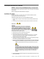
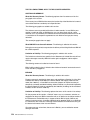
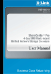
10. If you are connecting the controller either directly to SAS or SATA disk drives or to
a backplane, connect the SAS cable to the active SAS internal connector on the
controller and connect the other end to the backplane or the SAS/SATA drives. To
identify the active SAS internal connector, see Figure 5.
Internal SAS connector
Mounting bracket
Battery connector
External mini-SAS
connector
Not currently used
Figure 5. ServeRAID-8s
11. Replace the server cover.
12. Reconnect the cables and cords. See your server documentation if you need
detailed instructions.
13. Go to “Updating BIOS and Firmware Code” on page 33.
Installing the Backup Battery for ServeRAID-8s
1. Using the appropriate static protection, remove the controller from your computer.
2. Position the battery module with the label facing
towards you (that is, battery module facing away
from the controller).
3. Align the battery module with the corresponding
holes on the controller, and secure it in place
using the fasteners provided (as shown at right).
4. Plug the connector cable into the battery
connector on the controller.
5. Reinstall the controller.
6. Restart your computer.
When you restart, your computer screen remains blank while the controller
initializes the new battery module. This may take a few minutes. When
initialization is complete, the boot process continues as expected.
You must allow this initialization process to complete. If you do not, your
battery module will not work and your system may not boot. Note that this process
occurs only once—it does not occur on subsequent restarts.
7. The battery module is now installed and automatically starts charging. The
indicator light on the controller (located immediately above the installed battery)
remains on until the battery is fully charged. It may take several hours to fully
charge the battery.
16
IBM ServeRAID: User’s Reference
When the battery is fully charged, you may want to enable the option to write back
cache only when the battery is charged. You can do so using the Adaptec RAID
Controller utility or IBM ServeRAID Manager. Refer to the IBM ServeRAID User’s
Guide or ServeRAID Manager online help for details.
WARNING
There is a risk of explosion if the battery is replaced by an incorrect type.
Dispose of used batteries according to the instructions.
Chapter 2. Installing a ServeRAID-8i, ServeRAID-8k, ServeRAID-8k-l, or ServeRAID-8s Controller
17
18
IBM ServeRAID: User’s Reference
Chapter 3. RAID Technology Overview
Redundant array of independent disks (RAID) is the technology of grouping several
physical drives in a computer into one or more logical drives. Each logical drive
appears to the operating system as a single drive. This grouping technique greatly
enhances logical-drive capacity and performance beyond the physical limitations of a
single physical drive.
When you group multiple physical drives into a logical drive, the ServeRAID controller
can transfer data in parallel from the multiple drives. This parallel transfer yields datatransfer rates that are many times higher than with non-grouped drives. This increased
speed makes the system better able to meet the throughput (the amount of data
processed in a given amount of time) or productivity needs of the multiple-user
network environment.
The ability to respond to multiple data requests provides not only an increase in
throughput, but also a decrease in response time. The combination of parallel
transfers and simultaneous responses to multiple requests enables disk drives to
provide a high level of performance in network environments.
Note: If you already understand these concepts, go to Chapter 4, “Configuring the
ServeRAID-8i, ServeRAID-8k, ServeRAID-8k-l, or ServeRAID-8s Controllers”
on page 33.
Stripe-Unit Size
With RAID technology, data is striped across a group of physical drives. This datadistribution scheme complements the way the operating system requests data.
The granularity at which data is stored on one drive of the logical drive before
subsequent data is stored on the next drive of the logical drive is called the stripe-unit
size.
You can set the stripe-unit size to 16, 32, 64, 128, 256 (the default), 512 or 1024 KB.
You can maximize the performance of your ServeRAID controller by setting the stripeunit size to a value that is close to the size of the system I/O requests. For example,
performance in transaction-based environments, which typically involve large blocks
of data, might be optimal when the stripe-unit size is set to 64 KB or 128 KB. However,
performance in file and print environments, which typically involve multiple small
blocks of data, might be optimal when the stripe-unit size is set to 16 KB.
The collection of stripe units, from the first drive of the logical drive to the last drive of
the logical drive, is called a stripe.
Note: The maximum supported stripe size for RAID 6 and RAID 60 is dependent on
the number of drives in the array. In general, the more drives in the array the
smaller the maximum supported stripe size.
© Copyright IBM Corp. 2007
19
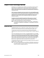
Selecting a RAID Level and Tuning Performance
Disk logical drives are used to improve performance and reliability. The amount of
improvement depends on the application programs that you run on the server and the
RAID levels that you assign to the logical drives.
Each RAID level provides different levels of fault-tolerance (data redundancy),
utilization of physical drive capacity, and read and write performance. In addition, the
RAID levels differ in regard to the minimum and maximum number of physical drives
that are supported.
When selecting a RAID level for your system, consider the following factors.
RAID level
Data
redundancy
Physical drive
capacity
utilization
Read
performance
Write
performance
Built-in
spare
drive
Min.
number
of drives
Max.
number
of drives
Simple Volume
No
100%
Superior
Superior
No
1
1
RAID level-0
No
100%
Superior
Superior
No
2
16
RAID level-1
Yes
50%
Very high
Very high
No
2
2
RAID level-1E^
Yes
50%
Very high
Very high
No
3
16
RAID level-5^
Yes
67% to 94%
Superior
High
No
3
16
RAID level5EE**
Yes ^^
50% to 88%
Superior
High
Yes
4
16
RAID level-6^
Yes
50% to 88%
Very high
Fair
No
4
16
RAID level-10
Yes
50%
Very high
Very high
No
4
16
RAID level-50**
Yes
67% to 94%
Superior
High
No
6
128
RAID level-60**
Yes
50% to 88%
Very high
Fair
No
8
128
Spanned
Volume
No
100%
Superior
Superior
No
2
48
RAID Volume
No
50% to 100%
Very high to
Superior *
Fair to
Superior *
No
2
48
* Depends upon underlying RAID level.
** Available with ServeRAID-8i only.
^ Not available with ServeRAID-8k-l.
^^ RAID level-5EE is not redundant while it is compressing.
Physical drive utilization, read performance, and write performance depend on the
number of drives in the logical drive. Generally, the more drives in the logical drive, the
better the performance.
20
IBM ServeRAID: User’s Reference
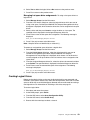
Supported RAID levels
The ServeRAID-8i controller supports RAID level-0, level-1, level-1E, level-5, level5EE, level-6, level-10, level-50, and level-60. The ServeRAID-8k controller supports
RAID level-0, level-1, level-1E, level-5, level-6, and level-10. The ServeRAID-8k-l
controller supports RAID level-0, level-1, and level-10. The ServeRAID-8s controller
supports RAID level-0, level-1, level-1E, level-5, level-6, level-10, and level-50.
ServeRAID-8i, ServeRAID-8k, ServeRAID-8k-l, and ServeRAID-8s controllers also
support the following additional RAID levels:
•
Simple Volume — a single disk drive or segment; not redundant.
•
Spanned Volume — two or more disk drives or segments with the same or
different capacity, connected end-to-end. A spanned volume offers no redundancy
or performance advantage over a single drive.
•
RAID Volume — two or more logical drives with the same RAID level, connected
end-to-end. The logical drives may have the same or different capacity and are
not striped together; they may be redundant, depending on the RAID level.
Note: RAID volumes can be created from RAID level-0, RAID level-1, or RAID level-5
members, but RAID levels cannot be mixed within the same RAID volume.
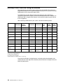
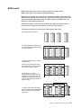
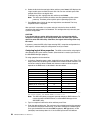
RAID Level-0
RAID level-0 stripes the data across all the drives in the logical drive. This offers
substantial speed enhancement but provides no data redundancy. RAID level-0
provides the largest storage capacity of the RAID levels that are offered, because no
room is taken for redundant data or data-parity storage.
RAID level-0 requires a minimum of two drives and, depending upon the level of
firmware and the stripe-unit size, supports a maximum of 8 or 16 drives.
The following illustration shows an example of a RAID level-0 logical drive.
Chapter 3. RAID Technology Overview
21
Start with two physical drives.
Create a logical drive using two physical drives.
The data is striped across the drives, creating blocks.
Notice that the data is striped across all the drives in
the logical drive, but no redundant data is stored.
1
2
3
4
5
6
7
8
A physical drive failure within the logical drive results in loss of data in the logical drive
assigned RAID level-0, but only in that logical drive. Logical drives assigned RAID
level-1, level-1E, level-5, level-5EE, or level-6 do not lose data.
Note: RAID level-5EE is not redundant while it is compressing, so if a drive failure
occurs during this state, data loss is possible.
When you replace a failed drive, the ServeRAID controller can rebuild all the RAID
level-1, level-1E, level-5, level-5EE, and level-6 logical drives automatically onto the
replacement physical drive. However, any data stored in a failed RAID
level-0 logical drive is lost.
Although the risk of data loss is present, you might want to assign RAID level-0 to a
logical drive to take advantage of the speed this RAID level offers. You can use this
logical drive to store data that you back up each day and can re-create easily. You also
might want to use a RAID level-0 logical drive when you require maximum capacity.
RAID level-0 offers the following advantages and disadvantages.
22
Advantages
Disadvantages
•
Substantial speed enhancement
•
Maximum utilization of physical drive
storage capacity, because no room is
taken for redundant data or data-parity
storage
No data redundancy, resulting in data loss in
the event that a physical drive fails
IBM ServeRAID: User’s Reference
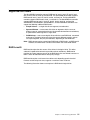
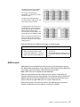
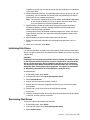
RAID Level-1
RAID level-1 uses data mirroring. Two physical drives are combined into a logical
drive, and data is striped across the logical drive. The first half of a stripe is the original
data; the second half of a stripe is a mirror (that is, a copy) of the data, but it is written
to the other drive in the RAID level-1 logical drive.
RAID level-1 provides data redundancy and high levels of performance, but the
storage capacity is diminished. Because the data is mirrored, the capacity of the
logical drive when assigned RAID level-1 is 50% of the drive capacity.
RAID level-1 requires two physical drives.
The following illustration shows an example of a RAID level-1 logical drive.
Start with two physical drives.
Create a logical drive using the two physical drives.
The data is striped across the drives.
Notice that the data on the drive on the right is a copy
of the data on the drive on the left.
1
1
2
2
3
3
4
4
With RAID level-1, if one of the physical drives fails, the controller switches read and
write requests to the remaining functional drive in the RAID level-1 logical drive.
RAID level-1 offers the following advantages and disadvantages.
Advantages
Disadvantages
•
100% data redundancy
•
High performance
Allows only 50% of the physical drive storage
capacity to be used
Chapter 3. RAID Technology Overview
23
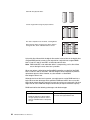
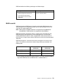
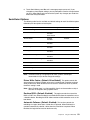
RAID Level-1 Enhanced
RAID level-1 Enhanced (RAID level-1E) combines mirroring and data striping. This
RAID level stripes data and copies of the data across all of the drives in the logical
drive. As with the standard RAID level-1, the data is mirrored, and the capacity of the
logical drive is 50% of the drive capacity.
Note: RAID level-1E is not supported on ServeRAID-8k-l.
RAID level-1E has a similar profile to RAID level-1; it provides data redundancy and
high levels of performance, but the storage capacity is diminished. However, RAID
level-1E allows a larger number of physical drives to be used.
RAID level-1E requires a minimum of three drives and, depending upon the level of
firmware and the stripe-unit size, supports a maximum of 8 or 16 drives.
The following illustration is an example of a RAID level-1E logical drive.
Start with three physical drives.
Create a logical drive using the physical
drives.
The data is striped across the drives, creating
blocks.
Notice that the stripe labeled ∗ is the data
stripe and the stripe labeled ∗∗ is the copy of
the preceding data stripe. Also, notice that
each block on the mirror stripe is shifted one
drive.
*
**
1
2
3
3
1
2
*
4
5
6
**
6
4
5
With RAID level-1E, if one of the physical drives fails, the ServeRAID controller
switches read and write requests to the remaining functional drives in the RAID level1E logical drive.
RAID level-1E offers the following advantages and disadvantages:
24
Advantages
Disadvantages
•
100% data redundancy
•
High performance
Allows only 50% of the physical drive storage
capacity to be used
IBM ServeRAID: User’s Reference
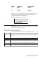
RAID Level-5
RAID level-5 stripes data and parity across all drives in the logical drive.
Note: RAID level-5 is not supported on ServeRAID-8k-l.
RAID level-5 offers both data protection and increased throughput. When you assign
RAID level-5 to a logical drive, the capacity is reduced by the capacity of one drive (for
data-parity storage). RAID level-5 gives you higher capacity than RAID level-1, but
RAID level-1 offers better performance.
RAID level-5 requires a minimum of three drives and, depending upon the level of
firmware and the stripe-unit size, supports a maximum of 8 or 16 drives.
The following illustration is an example of a RAID level-5 logical drive.
Start with four physical drives.
Create a logical drive using three of
the physical drives, leaving the fourth
as a hot-spare drive.
The data is striped across the drives,
creating blocks.
Notice that the storage of the data
parity (denoted by ∗) also is striped,
and it shifts from drive to drive.
A parity block (∗) contains a
representation of the data from the
other blocks in the same stripe. For
example, the parity block in the first
stripe contains data representation of
blocks 1 and 2.
If a physical drive fails in the logical
drive, the data from the failed physical
drive is reconstructed onto the hotspare drive.
1
2
4
5
*
6
*
7
*
3
*
3
5
*
*
8
2
1
4
*
6
*
8
7
Chapter 3. RAID Technology Overview
25
RAID level-5 offers the following advantages and disadvantages.
Advantages
Disadvantages
•
100% data protection
•
Offers more physical drive storage
capacity than RAID level-1 or level-1E
Lower performance than RAID level-1 and
level-1E
RAID Level-5E Enhanced
RAID level-5E Enhanced (RAID level-5EE) is the same as RAID level-5, but with a
distributed spare drive and faster rebuild times. This RAID level stripes data and parity
across all of the drives in the logical drive.
Note: RAID level-5EE is only supported on ServeRAID-8i.
RAID level-5EE offers both data protection and increased throughput. When a logical
drive is assigned RAID level-5EE, the capacity of the logical drive is reduced by the
capacity of two physical drives (one for parity and one for the spare).
The spare drive is actually part of the RAID level-5EE logical drive, interleaved with
the parity blocks, as shown in the following example. This enables data to be
reconstructed more quickly if a physical drive in the logical drive fails.
Note: RAID level-5EE is not redundant while it is compressing. If a drive failure
occurs during this state, data loss is possible.
RAID level-5EE requires a minimum of four drives and, depending upon the level of
firmware and the stripe-unit size, supports a maximum of 8 or 16 drives. RAID level5EE is also firmware-specific.
The following illustration is an example of a RAID level-5EE logical drive.
Start with four physical drives.
Create a logical drive using all four
physical drives.
26
IBM ServeRAID: User’s Reference
The data is striped across the drives,
creating blocks in the logical drive.
The storage of the data parity
(denoted by ∗) is striped, and it shifts
from drive to drive.
The spare drive (denoted by S) is
interleaved with the parity blocks, and
it also shifts from drive to drive.
If a physical drive fails, the data from
the failed drive is reconstructed. The
logical drive undergoes compaction,
and the distributed spare drive
becomes part of the logical drive. The
logical drive remains RAID level-5EE.
When you replace the failed drive, the
data for the logical drive undergoes
expansion and returns to the original
striping scheme.
RAID level-5EE offers the following advantages and disadvantages.
Advantages
Disadvantages
•
100% data protection
•
•
Offers more physical drive storage
capacity than RAID level-1 or level-1E
Lower performance than RAID level-1
and level-1E
•
Not redundant during compression, so a
drive failure at this time may result in data
loss
•
Higher performance than RAID level-5
RAID Level-6
RAID level-6 is basically RAID level-5 with two sets of parity information instead of
one. RAID level-6 stripes blocks of data and parity across logical drive like RAID level5, but adds a second set of parity information for each bit of data.
Note: RAID level-6 is not supported on ServeRAID-8k-l.
When you assign RAID level-6 to a logical drive, the capacity is reduced by the
capacity of two drives (for data-parity storage). This second set of parity information is
added to improve fault tolerance. RAID level-6 can handle two simultaneous drive
failures, where other single RAID levels can at most handle only one.
RAID level-6 requires a minimum of four drives and, depending upon the level of
firmware and the stripe-unit size, supports a maximum of 16 drives.
Chapter 3. RAID Technology Overview
27
The following illustration is an example of a RAID level-6 logical drive.
Start with six physical drives.
Create a logical drive using four
physical drives, leaving two drives
for data parity.
The data is striped across the
drives, creating blocks in the
logical drive.
The storage of the data parity
(denoted by * and **) is striped,
and it shifts from drive to drive as it
does in RAID level-5.
If a single physical drive fails in the
logical drive, the logical drive is
degraded but continues to be fault
tolerant.
If a second physical drive fails in
the logical drive, the data from both
failed drives is reconstructed onto
the data parity drives, and the data
for the logical drive returns to the
original striping scheme.
Note: The preceding RAID level-6 layout is a high-level design, for general
information only. The actual layout is more complicated.
28
IBM ServeRAID: User’s Reference
RAID level-6 offers the following advantages and disadvantages.
Advantages
Disadvantages
•
100% data protection
•
Extremely high data fault tolerance
Lower performance than RAID level-5
because of two parity drives.
•
Can sustain two drive failures
•
Good solution for mission critical
applications
RAID Level-x0
RAID level-x0 refers to RAID level-10, level-50, and level-60. RAID level-x0 uses a
spanned logical drive. The operating system uses the spanned logical drive in the
same way as a regular logical drive.
Note: RAID level-50 and RAID level-60 are not supported on ServeRAID-8k or
ServeRAID-8k-l. RAID level-60 is not supported on ServeRAID-8s.
RAID level-x0 allows more physical drives in a logical drive. The benefits of using
RAID level-x0 are larger logical drives, increased performance, and increased
reliability. RAID level-0, level-1E, level-5, and level-5EE cannot use more than 16
physical drives in a logical drive; however, RAID level-10, level-50 and level-60 support
128 drives.
RAID level-x0 requires a minimum of four drives and supports a maximum of 128
drives.* The minimum and maximum number of legs (subarrays) is defined in the
following table:
*
RAID Level
Minimum # of Legs
(subarrays)
Maximum # of Legs
(subarrays)*
RAID level-10
2
64
RAID level-50
2
8
RAID level-60
2
8
For this release, the maximum number of drives is 12, so the maximum number of
legs will be: RAID level-10—6, RAID level-50—4, RAID level-60—3.
Chapter 3. RAID Technology Overview
29
The following illustration is an example of a RAID level-10 logical drive.
Start with six physical drives.
Create three logical drives
(labeled A, B, and C), each
using two physical drives.
A
Then create a spanned
logical drive(labeled as ∗)
that spans the three logical
drives.
Notice that, in each logical
drive, the data on the drive
on the right is a copy of the
data on the drive on the left.
This is because the sublogical drives (A, B, and C)
are RAID level-1 in a RAID
level-10 implementation (see
the following table).
Then, create a logical drive
within the spanned logical
drive(∗). The data is striped
across this logical drive,
creating blocks (1-12). Notice
that none of these blocks are
redundant. This is because
the logical drive is RAID
level-0 in a RAID level-x0
implementation (see the
following table).
30
IBM ServeRAID: User’s Reference
*B
A
A sub-logical drive is created
within each logical drive(A, B,
and C). Then, the data is
striped across the physical
drives, creating blocks.
1
2
3
4
5
6
7
8
1
2
3
4
5
6
7
8
1 12
4 43
7 56
10 87
C
1
2
3
4
5
6
7
8
1
2
3
4
5
6
7
8
*B
A
1
2
3
4
5
6
7
8
C
*B
A
1
2
3
4
5
6
7
8
C
B
1
2
3
4
5
6
7
8
2 12
5 43
8 56
11 87
1
2
3
4
5
6
7
8
C
1
2
3
4
5
6
7
8
3 12
6 43
9 56
12 87
RAID level
Sub-logical drive
Spanned logical drive
10
RAID level-1
RAID level-0
50
RAID level-5
RAID level-0
60
RAID level-6
RAID level-0
With RAID level-10, level-50, and level-60, if one of the physical drives fails in a sublogical drive, the ServeRAID controller switches read and write requests to the
remaining functional drives in the sub-logical drive.
RAID level-x0 offers the following advantages.
Advantages
•
Supports up to 60 physical drives
•
Can sustain multiple two drive failures
•
100% data redundancy
Drive-State Descriptions
This section provides descriptions of the physical and logical drive states. ServeRAID
publications frequently refer to these states.
Physical-Drive-State Descriptions
The following table provides descriptions of the valid physical drive states.
Drive state
Meaning
Defunct
A physical drive in the online, hot-spare, or rebuild state has become defunct. It does not respond
to commands, which means that the ServeRAID controller cannot communicate properly with the
drive.
If a physical drive has become defunct, see “Rebuilding a Defunct Drive” on page 108.
Hot spare
A hot-spare drive is a physical drive that is defined for automatic use when a similar drive fails.
Online
The drive is online. It is functioning properly and is part of a logical drive.
Rebuilding
The drive is being rebuilt.
For more information on rebuilding a drive, see “Rebuilding a Defunct Drive” on page 108.
Ready
The ServeRAID controller recognizes a ready drive as being available for definition.
Verifying
Check a physical drive for inconsistent or bad data.
Chapter 3. RAID Technology Overview
31
Logical-Drive-State Descriptions
The following table provides descriptions of the valid logical drive states.
Drive state
Meaning
Clearing
Clearing is usually automatic when you create a logical drive. Clearing a logical drive erases the
first 1024 sectors on the drive and prevents access to any data previously stored on the drive.
Note: Data cannot be read or written to a drive while it is undergoing a “clear” process.
Critical
A RAID level-1, level-1E, level-5, level-5EE, level-10, or level-50 logical drive that contains a
defunct physical drive is in the critical state. A RAID level-6 or level-60 logical drive that contains
two defunct physical drives is also in a critical state. A critical logical drive is accessible, despite a
physical drive failure.
Attention: If the state of the logical drive is critical, see “Rebuilding a Defunct Drive” on page 108.
Critical migrating
A logical drive in the critical state that is undergoing a logical-drive migration (LDM).
Degraded
RAID level-6 and RAID level-60 will move to a Degraded state if one drive is defunct.
Degraded migrating
(For RAID level-6 and RAID level-60 only) A logical drive in the degraded state that is undergoing a
logical-drive migration (LDM).
Impacted
For RAID level-1, level-1E, level-5, level-6, level-5EE, level-10, level-50, and level-60, if the drive
fails during initialization or you stop the initialization process before it is complete, the drive enters
the state Impacted. This means that the striping/synchronization process has not completed and
you need to resynchronize. This situation can occur in two cases:
• When creating a container, during the automatic background synchronization
• When doing data scubbing (with background synchronization)
Migrating
The logical drive is undergoing a logical-drive migration; that is, a change in RAID levels, a change
in logical-drive size and/or change in logical drive stripe size.
Offline
The logical drive is offline and not accessible. This state occurs when one of the following is true:
•
One or more physical drives in a RAID level-0 logical drive are defunct.
•
Two or more physical drives in a RAID level-1, level-1E, or level-5 logical drive are defunct.
•
Three or more drives in a RAID level-5EE logical drive or RAID level-6 logical drive are
defunct.
•
One or more drives in a RAID level-5EE logical drive fail while a compaction is in progress. If
the drive fails after the RAID level-5EE logical drive is in a compacted state, the array becomes
‘Critical.’
If any of these is true, see “Rebuilding a Defunct Drive” on page 108.
Okay
32
The logical drive is working properly. It is in a good, functional state.
IBM ServeRAID: User’s Reference
Chapter 4. Configuring the ServeRAID-8i, ServeRAID-8k,
ServeRAID-8k-l, or ServeRAID-8s Controllers
This chapter provides information about obtaining ServeRAID updates; updating
ServeRAID BIOS and firmware code; upgrading your HostRAID SAS/SATA controller
to a ServeRAID-8i, ServeRAID-8k, ServeRAID-8k-l, or ServeRAID-8s; and
configuring your ServeRAID-8i, ServeRAID-8k, ServeRAID-8k-l, and ServeRAID-8s
controllers.
Obtaining ServeRAID Updates
IBM periodically makes updated versions of the ServeRAID software available from
the IBM Support page on the World Wide Web. Go to
http://www304.ibm.com/jct01004c/systems/support/supportsite.wss/docdisplay?Indocid=MIGR65723&brandid=5000008.
Note: If you download ServeRAID software, you must download and install all
ServeRAID software at the same time. This will ensure that all levels of the
software are compatible. The ServeRAID software includes:
•
BIOS and firmware code
•
Device drivers
•
ServeRAID Manager program
•
Command-line programs
If you do not have access to the World Wide Web, contact your place of purchase,
your IBM reseller, or your IBM marketing representative for replacement CDs.
Updating BIOS and Firmware Code
You must have the latest BIOS and firmware code installed on your server before
configuring the ServeRAID controller
Complete the following steps to update the levels of BIOS and firmware code:
1. Insert the IBM ServeRAID Support CD into the server CD-ROM drive, and turn on
the server.
The IBM ServeRAID ROM Update wizard automatically starts. The ROM (readonly memory) update wizard is a program that updates the BIOS and firmware
code on ServeRAID controllers. The wizard automatically identifies and scans
each ServeRAID controller.
If the BIOS and firmware code require updating, a report screen opens with the
following information:
© Copyright IBM Corp. 2007
•
Controller types found.
•
Controller slot number, if known.
•
Firmware version.
•
BIOS version.
•
Update status. If a controller has outdated BIOS or firmware code, the
ROM Update wizard marks the controller as a candidate for update.
33
The IBM ServeRAID ROM Update wizard asks if you want to update. You decide
whether to update, but you must update all or none of the controllers in your
server; you cannot selectively update.
2. If you want to update your ServeRAID controllers, click Update. If the wizard
detects an error, an error message appears and you are prompted to insert a
diskette into your diskette drive. The wizard saves details about the error to a file
on the diskette.
If you do not want to update your ServeRAID controllers, click Cancel.
3. ServeRAID automatically restarts the server after the update.
Upgrading SAS/SATA HostRAID to the ServeRAID controller
Use the following procedures to import a RAID configuration from a HostRAID
SAS/SATA controller to a ServeRAID-8i, ServeRAID-8k, ServeRAID-8k-l, or
ServeRAID-8s controller.
Please note before you begin the upgrade:
• Only RAID level-0, RAID level-1, and Simple Volumes are supported.
• The verifying RAID level-1 will import and restart the Verify task.
• There is no hot spare support.
• Once a HostRAID configuration is merged or imported to a ServeRAID
controller, it cannot return to HostRAID. All data stored on the array would be
lost.
• Arrays that are clearing, degraded, rebuilding, or in a mixed state (one
failed/degraded RAID level-1 and one optimal RAID level-1) cannot be
imported.
Upgrading ServeRAID-8e SAS/SATA HostRAID to a ServeRAID-8i SAS
controller
To add a ServeRAID-8i controller to a server with an existing ServeRAID-8e
HostRAID card, do the following:
1. Follow the instructions for “Installing the ServeRAID-8i Controller” on page 11 to
install the ServeRAID-8i controller.
2. Power up the server. The BIOS will automatically detect and import the RAID as a
“foreign array” and will display the following message:
“Following foreign arrays found”.
Array#0: RAIDxx
Accept the configuration [Enter]
3. Press Enter to accept the configuration. The imported array configuration can be
seen using the BIOS ACU utility, the bootable SeverRAID Manager, the OSinstalled ServeRAID Manager, and the ARCCONF command line utility.
Note: After you import the array, the OS will see the logical disk for the first time.
You will need to follow your OS procedure for an imported array partition.
Configuring the ServeRAID Controller
This section provides information about starting and using the ServeRAID Manager
program to configure your ServeRAID-8i, ServeRAID-8k, ServeRAID-8k-l, or
ServeRAID-8s controller, view the ServeRAID configurations and associated devices,
change controller settings, monitor your controller, and more.
34
IBM ServeRAID: User’s Reference
The information in this section focuses on using the ServeRAID Manager program in
bootable-CD mode to configure your ServeRAID SAS controller or to change specific
settings.
Using ServeRAID Manager
The ServeRAID Manager program operates in two ways:
• Bootable-CD mode
• As an installed software program
When you run the ServeRAID Manager program from the bootable IBM ServeRAID
Support CD, you are using bootable-CD mode. Bootable-CD mode lets you to
configure your controller before you install your operating system. After you have
configured the controller and installed the operating system, you also can use
bootable-CD mode to change specific controller settings. For additional information,
see “Viewing your configuration” on page 41.
To run the ServeRAID Manager program in bootable-CD mode, turn on the server;
then, insert the IBM ServeRAID Support CD (or the CD that contains the ServeRAID
Manager program that came with your server) into the CD-ROM drive.
If the ServeRAID Manager program detects unconfigured controllers and ready drives,
the program automatically starts the Configuration wizard, and a window similar to the
one shown in Figure 6 opens.
Figure 6. “Configuration wizard” window
You can use the Configuration wizard to create logical drives for your ServeRAID
controller. The Configuration wizard provides two configuration options: Express and
Custom. Express configuration automatically configures your ServeRAID controller,
and you can use Custom configuration to configure your controller manually. If you
want to use RAID level-1E, RAID level-5EE, RAID level-6, or RAID level-x0, you must
use Custom configuration. For more information about RAID levels, see Chapter 3,
“RAID Technology Overview” on page 19.
Using Express configuration: Express configuration automatically
configures your ServeRAID controller. This feature:
Chapter 4. Configuring the ServeRAID-8i, ServeRAID-8k, ServeRAID-8k-l, or ServeRAID-8s Controllers
35
•
•
Creates logical drives by grouping together same-sized physical drives.
Assigns a RAID level based on the number of physical drives in a logical
drive:
•
A logical drive with one physical drive (or drive segment) is assigned a
Simple Volume.
•
A logical drive with two physical drives is assigned RAID level-1.
•
A logical drive with three or more physical drives is assigned RAID level-5.
Complete the following steps to use Express configuration:
1. In the ServeRAID Manager tree, click the ServeRAID controller that you want to
configure.
2. From the toolbar, click
(Create).
3. Click Express configuration.
4. Click Next. The “Configuration summary” window opens.
5. Review the information that is displayed in the “Configuration summary” window.
To change the configuration, click Modify logical drives.
Figure 7. “Configuration summary” window (Express Configuration)
Note: Some operating systems have size limitations for logical drives. Before you
save the configuration, verify that the size of the logical drive is appropriate
for your operating system.
6. Click Apply; then, click Yes when asked if you want to apply the new
configuration. The configuration is saved in the ServeRAID controller and in the
physical drives.
7. When you have completed configuring your controller, you can change certain
controller settings. See “Fine-Tuning your Configuration” on page 39 for more
information. If you do not want to change any settings, exit from the ServeRAID
Manager program, and remove the CD from the CD-ROM drive.
8. Restart the server.
9. Continue with Chapter 5, “Installing ServeRAID Device Drivers” on page 43.
36
IBM ServeRAID: User’s Reference
Note: If you are configuring your boot ServeRAID controller, you must install the
device driver while installing the operating system.
Using Custom configuration: Select Custom configuration to configure your
controller manually. Complete the following steps to use Custom configuration:
1. In the ServeRAID Manager tree, click the ServeRAID controller that you want to
configure.
2. From the toolbar, click
(Create).
3. Click Custom configuration.
4. Click Next to open the Create Logical Drives window.
Figure 8. “Create logical drives” window
5. Select a RAID level either from the top list or by expanding the Advanced Settings
menu and selecting from the Advanced Settings list. (For more information, see
“Supported RAID levels” on page 21.)
Note: If you are creating a RAID volume, you must create the individual
drives first, then run the Configuration Wizard again to create the RAID
volume. Redundant logical drives that auto synchronize must complete
synchronization before they can be used to create a RAID volume.
Chapter 4. Configuring the ServeRAID-8i, ServeRAID-8k, ServeRAID-8k-l, or ServeRAID-8s Controllers
37
6. Click Next to open the Configure Logical Drives window.
Figure 9. “Configure logical drives” window
7. Select the physical drives you want to include in the logical drive and modify the
Advanced Settings as appropriate.
Notes:
a. Some operating systems have size limitations for logical drives. Before
you save the configuration, verify that the size of the logical drive is
appropriate for your operating system.
b.
38
IBM ServeRAID: User’s Reference
Typically, the first logical drive defined on the first ServeRAID controller
found by system BIOS during startup will be your boot drive.
8. Click Next. The “Configuration summary” window opens.
Figure 10. “Configuration summary” window (Custom Configuration)
9. Review the information that is displayed in the “Configuration summary” window.
To change the configuration, click Back.
10. Click Apply; then, click Yes when asked if you want to apply the new
configuration. The configuration is saved in the ServeRAID controller and in the
physical drives.
11. When you have completed configuring your controller, you can change certain
controller settings. See “Fine-Tuning your Configuration” on page 39 for more
information. If you do not want to change any settings, exit from the ServeRAID
Manager program, and remove the CD from the CD-ROM drive.
12. Restart the server.
13. Continue with Chapter 5, “Installing ServeRAID Device Drivers” on page 43.
Note: If you are configuring your boot ServeRAID controller, you must install the
device driver while installing the operating system.
Fine-Tuning your Configuration
Before you store data on the controller, you will need to determine the correct stripeunit size for your configuration and set the write-cache mode, if necessary.
Changing the stripe-unit size: The stripe-unit size determines the amount of
data written to one segment of a logical drive before the next segment is used for
subsequent data. Stripe-unit size is configured while creating the logical drive (see
Figure 9). The ServeRAID-8i, ServeRAID-8k, ServeRAID-8k-l, and ServeRAID-8s
controllers support stripe-unit sizes of 16 KB, 32 KB, 64 KB, 128 KB, 256 KB, 512 KB,
and 1024 KB (default is 256 KB). You can change the stripe-unit size of an existing
logical drive by expanding or migrating the drive.
Note: The maximum supported stripe size for RAID 6 and RAID 60 is dependent on
the number of drives in the array. In general, the more drives in the array the
smaller the maximum supported stripe size.
Chapter 4. Configuring the ServeRAID-8i, ServeRAID-8k, ServeRAID-8k-l, or ServeRAID-8s Controllers
39
Complete the following steps to change the stripe-unit size:
1. In the Logical Devices view, right-click the logical drive you want to modify.
2. Select Expand or change logical drive to open the Configuration wizard.
3. Click Next. Expand Advanced Settings and select the new stripe-unit size for
your logical drive.
Note: Consider your server application environment when you select the stripeunit size setting.
Environment
®
Groupware (such as Lotus Notes
®
or Exchange)
Stripe-unit size
128 KB
Transaction processing database
128 KB
Decision support database
128 KB
Thin client environments
128 KB
File server (Windows 2000, Windows Server 2003, Novell NetWare)
64 KB
File server (other)
64 KB
Web server
64 KB
Other
64 KB
Setting the write-cache mode: Set the write-cache mode according to the
planned use of each logical drive. For logical drives where read and write performance
is important and data can be recovered, set the write-cache mode to write-back. For
logical drives where read and write performance is less important but data integrity is
a high priority, set the write-cache mode to write-through. If your controller has
battery-backed cache, the possibility of data loss in write-back mode is eliminated.
To change the write-cache mode on a logical drive, complete the following steps:
1. In the ServeRAID Manager tree, right-click the logical drive.
2. Click Configure write-cache.
Setting the read-cache mode: The read-cache mode enables and disables
read caching. When read-caching is enabled, the controller monitors read access to
the logical drive. If it detects a pattern, it pre-loads the cache with the data that seems
most likely to be read next. The default is enabled.
To change the read-cache mode on a logical drive, complete the following steps:
1. In the ServeRAID Manager tree, right-click the logical drive.
2. Click Configure read-cache.
40
IBM ServeRAID: User’s Reference
Viewing your configuration
You can use ServeRAID Manager to view information about RAID controllers and the
RAID subsystem (such as logical drives, hot-spare drives, and physical drives).
To view information, expand the ServeRAID Manager tree; then, click the relevant tree
object. Detailed information about the selected device appears in the right
pan
Figure 11. ServeRAID Manager window
To display available actions for an item, click the item in the ServeRAID Manager tree
and click Actions.
Chapter 4. Configuring the ServeRAID-8i, ServeRAID-8k, ServeRAID-8k-l, or ServeRAID-8s Controllers
41
Getting Assistance
For more information about ServeRAID Manager, see the on-line help system. To start
the help system, either click
on the toolbar or select an item from the Help menu.
Figure 12. ServeRAID Manager help menu
The help system (ServeRAID Assist) will open within the ServeRAID Manager
interface.
To learn more about the ServeRAID Manager objects and the actions that apply to
them, select an object, either in the tree or in the Physical and Logical device views;
then, click Actions ➔ Hints and tips. ServeRAID Manager Assist will start, and
information about the object will be displayed.
Figure 13. Hints and tips feature
42
IBM ServeRAID: User’s Reference
Chapter 5. Installing ServeRAID Device Drivers
The ServeRAID device drivers are provided on the IBM ServeRAID Support CD. The
IBM ServeRAID Installation Guide (INSTALL.PDF), located in the BOOKS directory on
the support CD, provides detailed instructions for installing the device drivers on the
following operating systems:
•
Microsoft Windows 2000 Server and Advanced Server
•
Microsoft Windows Server 2003 Standard Edition and Enterprise Edition
•
Microsoft Windows Server 2003 for EM64T
•
Microsoft Windows PE
•
Novell NetWare 6.5
•
Red Hat Enterprise Linux 3 AS/ES/WS for 32-bit kernels
•
Red Hat Enterprise Linux 3 AS/ES for EM64T 64-bit kernels
•
Red Hat Enterprise Linux 4 AS/ES/WS for 32-bit kernels
•
Red Hat Enterprise Linux 4 AS/ES for EM64T 64-bit kernels
•
Red Hat Enterprise Linux 5 AS/ES/WS for 32-bit kernels
•
Red Hat Enterprise Linux 5 AS/ES for EM64T 64-bit kernels
•
SuSE Linux Enterprise Server 9 for 32-bit kernels
•
SuSE Linux Enterprise Server 9 for EM64T kernels
•
SuSE Linux Enterprise Server 10 for 32-bit kernels
•
SuSE Linux Enterprise Server 10 for EM64T kernels
•
SuSE Linux Standard Desktop 9.0
•
SCO OpenServer 5.0.7
•
SCO OpenServer 6.0
•
SCO UnixWare 7.1.3
•
SCO UnixWare 7.1.4
•
Sun Solaris 10
If you are configuring your startup (boot) ServeRAID controller, you must install the
device driver while installing the operating system.
© Copyright IBM Corp. 2007
43
44
IBM ServeRAID: User’s Reference
Part 2. Utility programs
© Copyright IBM Corp. 2007
45
46
IBM ServeRAID: User’s Reference
Chapter 6. Using the ARC Utility
This chapter provides the information needed to start and use the Adaptec RAID
Configuration (ARC) utility.
The ARC utility is an embedded BIOS utility that you can use to configure your
ServeRAID-8i, ServeRAID-8k, or ServeRAID-8k-l SAS controller. It includes:
•
Array Configuration Utility (ACU)—Used to create, configure, and manage
logical drives. Also used to initialize and rescan drives.
•
SerialSelect—Used to change device and controller settings,
•
Disk Utilities—Used to format or verify media.
To run the ARC utility, press Ctrl+A when prompted by the following message during
system startup:
Press <Ctrl><A> for Adaptec RAID Configuration Utility
The ARC menu appears, presenting the following options:
•
Array Configuration Utility
•
SerialSelect Utility
•
Disk Utilities
Note: If there is more than one controller, a controller selection menu will appear
before the ARC menu, asking that users select a controller to configure.
To select an option from this menu, or from any of the menus within ARC, browse with
the arrow keys and then press Enter. In some cases, selecting an option displays
another menu. To return to the previous menu at any time, press Esc.
The following sections discuss each of these menu options.
Using the Array Configuration Utility
The Array Configuration Utility (ACU) enables you to manage, create, and delete
logical drives from the controller’s BIOS. You can also initialize and rescan drives.
You can use the ACU to create a bootable drive for the system. We recommend that
you configure the system to start from a logical drive instead of a single disk to take
advantage of the redundancy and performance features of logical drives. For details,
see “Making a logical drive bootable” on page 48.
Managing Logical Drives
Use the Manage Arrays option to view drive properties and members, make a logical
drive the boot drive, manage failover assignments, and delete logical drives. The
following sections describe these operations in greater detail.
Viewing logical drive properties To view the properties of an existing drive:
1. At the BIOS prompt, press Ctrl+A.
2. From the ARC menu, select Array Configuration Utility.
3. From the ACU menu, select Manage Arrays.
© Copyright IBM Corp. 2007
47
4. From the List of Arrays dialog box, select the logical drive you want to view
information on and then press Enter.
Single Level Arrays Only—For RAID levels 0, 1, 1E, 5, and 6, the Array
Properties dialog box shows detailed information on the physical disks.
Dual-Level Arrays—For RAID levels 10, 50, and 60, highlight the displayed
member to view detailed information on the physical disks, and then press Enter
to display the second level. Press Enter again to display the physical disks
associated with the logical drive.
Note: A failed drive is displayed in a different text color.
5. Press Esc to return to the previous menu.
Making a logical drive bootable You can make a logical drive bootable so
that the system starts from the drive instead of from a stand-alone (single) disk. To
make a logical drive bootable:
1. At the BIOS prompt, press Ctrl+A.
2. From the ARC menu, select Array Configuration Utility.
3. From the ACU menu, select Manage Arrays.
4. Select the logical drive you want to make bootable and then press Ctrl+B. This
changes the selected drive’s number to 00, making it the controller’s boot drive.
5. Restart the system.
Notes:
•
If the controller is not a boot device, you can disable its runtime BIOS (see
“Runtime BIOS—(Default: Enabled)” on page 53). When the BIOS is disabled, it
does not occupy any of the expansion ROM region of the system’s memory map.
In a system with several expansion ROMs, disabling the BIOS may be helpful.
•
You cannot make a non-00 drive bootable while the drive is in a build/verify or
reconfiguration process.
•
The controller always uses the lowest numbered drive as its bootable drive. If you
delete Drive 00 for any reason, the next lowest numbered drive becomes the
bootable drive. Use the Ctrl+B option to mark the correct drive as the bootable
drive (by making it Drive 00).
•
If you want to boot from a stand-alone (single) disk drive, first create a volume on
that disk.
•
The system BIOS provides additional tools to modify the boot order. For more
information, refer to your system documentation.
Deleting logical drives To delete an existing logical drive:
CAUTION:
Back up the data on a logical drive before you delete it. When you delete the
drive, you loose all your data on the drive. You cannot restore deleted drives.
1. At the BIOS prompt, press Ctrl+A.
2. From the ARC menu, select Array Configuration Utility.
3. From the ACU menu, select Manage Arrays.
4. Select the logical drive you wish to delete and then press Delete.
5. In the Array Properties dialog box, press Delete again and then press Enter. The
following message is displayed:
Warning!! Deleting will erase all data from the array.
Do you still want to continue? (Yes/No):
48
IBM ServeRAID: User’s Reference
6. Select Yes to delete the logical drive or No to return to the previous menu.
7. Press Esc to return to the previous menu.
Managing hot spare drive assignments To assign a hot spare drive to a
logical drive:
1. Select Manage Arrays from the Main menu.
2. From the List of Arrays dialog box, select the logical drive to which you want to
assign a hot spare, and then press Ctrl+S. The Hotspare Management for Array
dialog box is displayed, which shows the drives that can be assigned as hot spare
drives.
3. Select a drive and then press Insert to assign the drive as a hot spare. The
specified drive is displayed in the Assigned Hotspares drives list.
4. Press Enter to save the hot spare drive assignment. The following message is
displayed:
Have you finished managing Hotspare drives?
5. Press Y (for yes) to return to the Main menu.
Note: Hotspare drives are identified by an askterisk (*).
To remove an assigned hot spare drive from a logical drive:
1. Select Manage Arrays from the Main menu.
2. From the List of Arrays dialog box, select the drive from which you want to
remove the assigned hot spare drive and press Ctrl+S. The Hotspare
Management for Array dialog box is displayed, which shows a list of drives that
can be assigned as hot spare drives and a list of drives that are assigned as hot
spare drives.
3. From the Assigned Hotspares drives list, select the drive to be removed and then
press Delete. The specified drive is displayed in the Select Hotspares drives list.
4. Press Enter to save the removed hot spare drive assignment. The following
message is displayed:
Have you finished managing Hotspare drives?
5. Press Y (for yes) to return to the Main menu.
Creating Logical Drives
Before creating logical drives, make sure the disks for the drive are connected and
installed in your system. Note that any disks with DOS partitions, disks with no usable
space, or disks that are uninitialized appear dimmed and cannot be used for creating a
new logical drive. For information on initializing a disk drive, see page 51.
To create a logical drive:
1. Shut down and restart the system.
2. At the BIOS prompt, press Ctrl+A.
3. From the ARC menu, select Array Configuration Utility.
4. From the ACU menu, select Create Array.
5. Browse with the arrow keys to select a channel.
Chapter 6. Using the ARC Utility
49
6. Select the disks for the new logical drive and then press Insert. ACU displays the
largest usable space available for each disk. You can use available space from
multiple disks for the new logical drive.
To deselect any disk, highlight the disk and then press Delete.
Note: The ACU cannot reliably find disks that were powered up after system
power-up. Therefore, power up disks prior to powering up the host.
7. Press Enter when all disks for the new logical drive are selected. The Array
Properties menu is displayed.
After you install a controller in a system and start it for the first time, the BIOS
announces the configuration it has detected. This configuration may not match your
system’s configuration.
CAUTION:
If you do not take any action within 30 seconds, the system automatically
accepts the configuration. If the configuration does not match your system,
reject it or enter the ARC utility. Otherwise, the logical drive configuration may
be erased.
If necessary, enter the ARC utility. Upon entering ARC, accept the configuration that
ARC reports, and then modify the configuration to suit your needs.
Assigning logical drive properties The ACU can be used to assign logical
drive properties only prior to drive creation. (After the drive is created, you must use
the ServeRAID Manager program.)
To assign properties to the new drive:
1. In the Array Properties menu, select a logical drive type and then press Enter. The
display shows only the drive types available for the number of drives selected. The
maximum number of drives allowed and minimum number of drives required
depend on the RAID level, as described in the table below.
RAID Level
Maximum Drives*
Minimum Drives
Simple volume (JBOD)
1
1
RAID 0
16
2
RAID 1
2
2
RAID 1E (8i, 8k, and 8s only)
16
3
RAID 5 (8i, 8k, and 8s only)
16
3
RAID 5EE (8i only)
16
4
RAID 6 (8i, 8k, and 8s only)
16
4
RAID 10
16
4
RAID 50 (8i and 8s only)
128
6
RAID 60 (8i only)
128
8
* These numbers reflect the maximum theoretical drives for the RAID levels. For
the current release, the maximum number of drives is 12.
Note: The ARC utility does not support spanned volumes or RAID volumes. To
create spanned and RAID volumes, use ServeRAID Manager or the
ARCCONF utility.
2. Type in an optional label for the drive and then press Enter.
3. Enter the desired drive size. The maximum size available based on the segments
you selected is displayed automatically. If you want to designate a different drive
size, type the desired size and select MB (megabytes), GB (gigabytes), or TB
(terabytes) from the drop-down list. If the available space from the selected
50
IBM ServeRAID: User’s Reference
segments is greater than the size you specify, the remaining space is available for
use in other drives.
4. Select the desired stripe size. The allowable stripe sizes are 16, 32, 64,128, 256
(the default), 512 and 1024KB. The default stripe size provides the best overall
performance in most network environments.
Note: The maximum supported stripe size for RAID 6 and RAID 60 is dependent
on the number of drives in the array. In general, the more drives in the
array the smaller the maximum supported stripe size.
5. Specify whether you want to enable read caching for the logical drive.When
Enabled (the default), caching is enabled, providing maximum performance.
When Disabled, caching is disabled.
Caching should usually be enabled to optimize performance, unless your data is
highly sensitive, or unless your application performs completely random reads,
which is unlikely.
6. Specify whether you want to enable write caching for the drive.
7. Specify the Initialization method to be used (Auto Synchronization, Clear, or
Quick).
8. When you are finished, select Done.
Initializing Disk Drives
If an installed disk does not appear in the disk selection list for creating a new logical
drive or if it appears grayed out, you need to initialize it before you can use it as part of
a logical drive.
CAUTION:
Initializing a disk overwrites the partition table on the disk and makes any data
on the disk inaccessible. If the drive is used in a logical drive, you may not be
able to use the drive again. Do not initialize a disk that is part of a boot drive.
The boot drive is the lowest numbered drive (normally 00) in the List of Arrays
dialog box. (See “Viewing logical drive properties” on page 47 for information
on determining which disks are associated with a particular drive.)
To initialize drives:
1. At the BIOS prompt, press Ctrl+A.
2. From the ARC menu, select Array Configuration Utility.
3. Select Initialize Drives.
4. Browse with the arrow keys to select a channel.
5. Browse with the arrow keys to highlight the disk you wish to initialize and then
press Insert.
6. Repeat step 5 until all the drives to be initialized are selected.
7. Press Enter.
8. Read the warning message, ensure that you have selected the correct disk drives
to initialize, and then press Y to continue.
Rescanning Disk Drives
To rescan the drives connected to the controller:
1. At the BIOS prompt, press Ctrl+A.
2. From the ARC menu, select Array Configuration Utility.
3. Select Rescan Drives.
Chapter 6. Using the ARC Utility
51
Using Secure Erase
The Secure Erase option is used to wipe off a disk, so that the data cannot be
retrieved. When this option is selected, the user is guided to select the drives to be
securely erased. Only drives that are not part of a logical drive can be securely
erased. While drives are undergoing Secure Erase, they are displayed in a different
color and cannot be selected again for the Secure Erase option.
To use Secure Erase:
1. At the BIOS prompt, press Ctrl+A.
2. From the ARC menu, select Array Configuration Utility.
3. Select Secure Erase.
4. Browse with the arrow keys to select a channel.
5. Browse with the arrow keys to highlight the disk you wish to securely erase and
then press Insert.
Note: Drives can only be selected for Secure Erase one at a time.
6. Press Enter.
7. Read the warning message, ensure that you have selected the correct disk drives
to initialize, and then press Y to continue.
Note: Press Enter in the disk select menu to view the progress of the Secure
Erase.
Restoring a RAID
If you have a broken or critical RAID 5 array, you’ll see a CTRL+R option available
on the Manage Arrays dialog. You can use this option to recover data from a RAID
5 and make this data available.
Note: When you press CTRL+R, a dialog appears warning you may permanently
lose all your data. Therefore, use this option only as a last resort and if you
don’t need the data on the RAID 5 array.
Using SerialSelect
SerialSelect allows you to change device and controller settings without opening the
computer cabinet or handling the card. With this utility, you can modify the Channel
Interface Definitions and Device Configuration Options.
To access SerialSelect:
1. When you turn on or restart your system, press Ctrl+A to access the ARC utility
when you see the following message:
Press <Ctrl><A> for Adaptec RAID Configuration Utility
2. If multiple controllers are installed, select the controller you want to configure and
then press Enter.
3. From the ARC menu, select SerialSelect Utility.
The PHY Configuration and Controller Configuration menu options are displayed.
See “SerialSelect Options” on page 53 for a list and descriptions of the options.
4. To select a SerialSelect menu option, browse with the arrow keys to the option
and then press Enter. In some cases, selecting an option displays another menu.
You can return to the previous menu at any time by pressing Esc.
5. To restore the original SerialSelect default values, press F6 from the PHY
Configuration or the Contoller Configuration menu.
52
IBM ServeRAID: User’s Reference
6. To exit SerialSelect, press Esc until a message prompts you to exit. (If you
changed any host adapter settings, you are prompted to save the changes before
you exit.) Select Yes to exit and restart the system. Any changes you made take
effect after the system boots.
SerialSelect Options
The following table lists the available and default settings for each SerialSelect option
followed by the descriptions of each option.
SerialSelect Options
Available Settings
Default Setting
Drives Write Cache
Enabled
Disabled
Drive Default
Drive Default
Runtime BIOS
Enabled
Disabled
Enabled
Automatic Failover
Enabled
Disabled
Enabled
Array Background Consistency Check Enabled
Disabled
Enabled
BBS Support
Enabled
Disabled
Enabled
Array based BBS Support
Enabled
Disabled
Disabled
Physical Drives Display During Post
Enabled
Disabled
Disabled
PHY Rate
Auto, 1.5, 3.0
Auto
CRC Checking
Yes, No
No (Disabled)
SAS Address
0-15
8
Controller Configuration
PHY Configuration
Note: The default settings are appropriate for most systems and Adaptec
recommends that you do not change the settings.
Drives Write Cache—(Default: Drive Default) This option controls the
drive performance. When Enabled, write cache is enabled and it provides maximum
driver performance. When disabled, no write cache is used on the drive. By default,
the drive’s setting is used.
Note: When Enabled, there is a slight possibility (less than the controller cache) of
data loss or corruption during a power failure.
Runtime BIOS—(Default: Enabled) This option controls the state of the
BIOS at POST time. When Enabled, the controller BIOS allows the controller to act as
a bootable device. Disabling the BIOS allows another suitable controller to act as the
boot device.
Automatic Failover—(Default: Enabled) This function controls the
rebuilding of a logical drive when a failed drive is replaced. When Enabled, the
controller automatically rebuilds a drive when the failed drive is replaced. When
Disabled, the logical drive must be rebuilt manually.
Chapter 6. Using the ARC Utility
53
Array Background Consistency Check—
(Default: Enabled) This function controls the media verification for all logical
drive types. When Enabled, the controller continuously performs read verification on
all logical drives to check disk medium integrity. In case a medium error is
encountered, the repair process will be performed on redundant logical drives.
Consistency checking processes reduce performance, especially under a heavy I/O
load.
BBS Support—(Default: Enabled) This function controls whether the BIOS
acts as a plug-and-play BIOS or a non-plug-and-play BIOS. When enabled (default), it
will install int13h drives in the second phase of the BBS. When disabled, will install
int13h at POST time.
Array based BBS Support—(Default: Disabled) When Enabled in
systems that support BBS, the controller presents attached bootable devices up to the
host system's BIOS for boot device selection. This is relevant for logical drives.
Physical Drives Display During POST—(Default:
Disabled) When Enabled, attached physical devices are displayed during system
POST. Displaying the devices adds a few seconds to the overall POST time.
PHY Configuration Options
PHY Rate—(Default: Auto) The data transfer rate between the controller and
devices. The default setting is Automatic, which allows the SAS card to adjust the
speed as needed.
CRC Checking—(Default: No) Determines whether the controller verifies the
accuracy of data transfer on the Serial bus. CRC Checking should be disabled on the
controller and all devices if any device supported by the controller does not support
CRC Checking.
SAS Address—(Default: 0) Specifies the 64-bit SAS address of the PHY
using a globally unique worldwide name (WWN) identifier.
Using the Disk Utilities
The disk utilities enable you to verify the media of your Serial Attached SCSI hard
disks. To access the disk utilities:
1. Turn on your computer and then press Ctrl+A when prompted to access the ARC
utility.
2. If multiple controllers are installed, select the controller you want to configure and
then press Enter.
Note: If there are more than 16 drives attached, users will have to use the <Page
Up> and <Page Down> keys to navigate the pages.
3. From the ARC menu, select Disk Utilities.
4. Select the desired disk and then press Enter.
You are offered the following options:
— Verify Disk Media—Scans the media of a disk drive for defects. Any errors
found are corrected.
— Format Disk—Formats a disk drive. This will erase any data on the disk.
54
IBM ServeRAID: User’s Reference
Viewing the Event Log
The BIOS-based event log stores all firmware events (configuration changes, drive
creation, boot activity, and so on).
The event log has a fixed size. Once full, old events are flushed as new events are
stored. Also, the log is volatile; therefore, it is cleared after each system restart.
To access the event log:
1. When you turn on or restart your system, press Ctrl+A to access the ARC when
prompted by the following message:
Press <Ctrl><A> for Adaptec RAID Configuration Utility
2. If multiple controllers are installed, select the controller you want to configure and
then press Enter.
3. From the ARC menu, press Ctrl+P.
The Controller Service Menu appears.
4. Select Controller Log Information and then press Enter. The current log is
displayed.
Chapter 6. Using the ARC Utility
55
56
IBM ServeRAID: User’s Reference
Chapter 7. Installing and Using the ARCCONF Command-Line
Program
This chapter provides the information needed to install, start, and use the ARCCONF
command-line program. ARCCONF is an advanced command-line program that you
can use to configure and manage the ARC-based ServeRAID-8i, ServeRAID-8k,
ServeRAID-8k-l, and ServeRAID-8s SAS controllers. The ARCCONF utility program is
provided on the IBM ServeRAID Support CD.
When using:
Go to:
Windows
“Installing ARCCONF for Windows” on page 57.
NetWare
“Installing ARCCONF for NetWare” on page 57.
Linux
“Installing ARCCONF for Red Hat Linux or SuSE Linux” on page 58.
OpenServer
“Installing ARCCONF for OpenServer” on page 59.
UnixWare
“Installing ARCCONF for UnixWare” on page 60.
Solaris
“Installing ARCCONF for Solaris” on page 60
Installing the ARCCONF Command-Line Program
Installing ARCCONF for Windows
Note: In Windows installations, the ARCCONF utility is part of the ServeRAID
application and is installed when ServeRAID Manager is installed.
To install ARCCONF for Windows using the IBM ServeRAID Applications CD:
1. Start the server.
2. After the operating system starts, insert the IBM ServeRAID Applications CD into
the CD-ROM drive.
3. When the installation program starts, follow the instructions on the screen to
install the program.
Installing ARCCONF for NetWare
ARCCONF for NetWare is bundled with ServeRAID Manager. If you have installed
ServeRAID Manager, ARCCONF will already be installed. If you have not installed
ServeRAID Manager, complete the following steps to install it:
1. Insert the IBM ServeRAID Applications CD into the CD-ROM drive.
2. From the command-line prompt, type the following command and press Enter:
load cdrom
3. From the command-line prompt, type the following command to determine the
volume of the CD-ROM drive, and press Enter:
volume
© Copyright IBM Corp. 2007
57
4. From the command-line prompt, type the following command to begin the
installation, and press Enter:
[volumename]\netware\manager\install
where [volumename] is the name of the CD-ROM volume discovered in Step 3.
The installation program starts.
5. Follow the instructions on the screen to install ServeRAID Manager.
Installing ARCCONF for Red Hat Linux or SuSE Linux
ARCCONF for Red Hat Linux and SuSE Linux is bundled with ServeRAID Manager. If
you have installed ServeRAID Manager, ARCCONF will already be installed. If you
have not installed ServeRAID Manager, complete the following steps to install it:
Notes:
1. The ServeRAID Manager program comes with the Sun Java Runtime
Environment (JRE).
2. If the ServeRAID Manager program has previously been installed on your server,
you must remove that version before upgrading. All customization files (such as
Managed system tree nodes and the Notification list) are saved and used in the
upgrade. To remove the ServeRAID Manager program from Linux, type:
rpm --erase RaidMan
3. When installed on Linux, this version of the ServeRAID Manager program
supports up to 12 ServeRAID controllers.
Complete the following steps to install the ServeRAID Manager program on Red Hat
Linux or SuSE Linux:
1. Insert the IBM ServeRAID Support CD into the CD-ROM drive.
2. If your CD-ROM drive automounts, type the following command and go to step 6
on page 52. Otherwise, go to step 3.
rpm --install /mnt/cdrom/linux_dir/manager/RaidMan-v.rr.arch.rpm
where linux_dir is linux or linux_x86_64, v is the ServeRAID version number, rr is
the ServeRAID release number, and arch is either i386 or x86_64.
3. If your CD-ROM drive does not automount, type the following command and press
Enter:
mount -r -t iso9660 /dev/cdromdevicefile /mountpoint
where cdromdevicefile is the specific device file for the CD-ROM block device, and
mountpoint is the point where you want to mount the CD file system.
4. Type the following command and press Enter:
rpm --install /mountpoint/linux_dir/manager/RaidMan-v.rr.i386.rpm
where mountpoint is the mount point used in step 3, linux_dir is the linux directory
used in step 3, v is the ServeRAID version number, and rr is the ServeRAID
release number.
5. When the installation is complete, type the following command:
umount /mountpoint
where mountpoint is the mount point used in step 3.
6. Press Enter. You can now remove the CD from the CD-ROM drive.
58
IBM ServeRAID: User’s Reference
Installing ARCCONF for OpenServer
ARCCONF for OpenServer is bundled with ServeRAID Manager. If you have installed
ServeRAID Manager, ARCCONF will already be installed. If you have not installed
ServeRAID Manager, complete the following steps to install it:
Notes:
1. The ServeRAID Manager program requires that you install either the Java
Development Kit (JDK) for SCO operating systems or the Java Runtime
Environment (JRE) for SCO operating systems, version 1.3.1. You can download
the JDK and JRE from the Caldera web site at http://www.caldera.com/download/.
2. If the ServeRAID Manager program has previously been installed on your server,
you must remove that version before upgrading. All customization files (such as
Managed system tree nodes and the Notification list) are saved and used in the
upgrade. To remove the ServeRAID Manager program from OpenServer, type:
rpm --erase RaidMan
3. When installed on OpenServer, this version of the ServeRAID Manager program
supports up to 12 ServeRAID controllers.
Complete the following steps to install the ServeRAID Manager program on
OpenServer:
1. Insert the IBM ServeRAID Applications CD into the CD-ROM drive.
2. Type the following command and press Enter:
mount -r -f HS,lower /dev/cd0 /mnt
3. Type the following command and press Enter:
cd /mnt/openserv/manager
4. Type the following command and press Enter:
sh ./mgr_inst
5. When the installation is complete, type the following command and press Enter:
cd /
6. Unmount the CD-ROM drive. Type the following command and press Enter:
umount /mnt
You can now remove the CD from the CD-ROM drive.
Chapter 7. Installing and Using the ARCCONF Command-Line Program
59
Installing ARCCONF for UnixWare
ARCCONF for UnixWare is bundled with ServeRAID Manager. If you have installed
ServeRAID Manager, ARCCONF will already be installed. If you have not installed
ServeRAID Manager, complete the following steps to install it:
Notes:
1. The ServeRAID Manager program requires that you install either the Java
Development Kit (JDK) for SCO operating systems or the Java Runtime
Environment (JRE) for SCO operating systems, version 1.3.1. You can download
the JDK and JRE from the Caldera web site at http://www.caldera.com/download/.
2. If the ServeRAID Manager program has previously been installed on your server,
you must remove that version before upgrading. All customization files (such as
Managed system tree nodes and the Notification list) are saved and used in the
upgrade. To remove the ServeRAID Manager program from UnixWare, type:
rpm --erase RaidMan
3. When installed on UnixWare, this version of the ServeRAID Manager program
supports up to 12 ServeRAID controllers.
Complete the following steps to install the ServeRAID Manager program on
UnixWare:
1. Insert the IBM ServeRAID Applications CD into the CD-ROM drive.
2. Type the following command and press Enter:
mount -r -F cdfs /dev/cdrom/cdromdevicefile /mnt
where cdromdevicefile is the specific device file for the CD-ROM block device.
Look in the /dev/cdrom directory to determine what cdromdevicefile is on your
server, for example, c0b0t010.
3. Type the following command and press Enter:
cd /mnt/unixware/manager
4. Type the following command and press Enter:
./mgr_inst
5. When the installation is complete, type the following command and press Enter:
cd /
6. Unmount the CD-ROM drive. Type the following command and press Enter:
umount /mnt
You can now remove the CD from the CD-ROM drive.
Installing ARCCONF for Solaris
ARCCONF for Solaris is bundled with ServeRAID Manager. If you have installed
ServeRAID Manager, ARCCONF will already be installed. If you have not installed
ServeRAID Manager, complete the following steps to install it:
Note: If a previous version of ServeRAID Manager is installed on your system,
you must remove it before beginning this installation. Any customization
files you created with the previous version are saved and used in the
upgrade. To remove ServeRAID Manager, type pkgrm RaidMan .
Complete the following steps to install the ServeRAID Manager program on Solaris:
1. Insert the IBM ServeRAID Applications CD.
The CD mounts automatically. (If it doesn’t, manually mount the CD using a
command similar to the one shown below. Refer to your operating system
documentation for detailed instructions.)
60
IBM ServeRAID: User’s Reference
mount -F hsfs -o ro/dev/dsk/c1t0d0s2/mnt
2. Install ServeRAID Manager:
pkgadd -d/<mount point>/solaris/manager/RaidMan.ds
3. Follow the on-screen instructions to complete the installation.
4. Eject or unmount the IBM ServeRAID Applications CD. Refer to your operating
system documentation for detailed instructions.
Starting the ARCCONF Command-Line Program
This section describes how to start the ARCCONF command-line program on the
supported operating systems. For a description of the available functions and their
parameters, see “ARCCONF Functions” on page 62.
To start ARCCONF on Windows, NetWare, Linux, or Solaris, type one of the following
commands and press Enter:
For Windows
c:\install_dir\arcconf.exe
For NetWare
load arcconf
For Linux
/usr/RaidMan/arcconf
For UnixWare/OpenServer
/opt/RaidMan/arcconf
For Solaris
/usr/RaidMan/arcconf
where install_dir is the directory where ServeRAID Manager is installed.
Using the ARCCONF Command-Line Program
The ARCCONF command-line program provides a quick way to configure and
manage your ARC-based ServeRAID SAS controllers. It allows you to:
•
Create backup copies of data.
•
Create logical drives; display or modify a limited set of configuration settings.
•
Copy ServeRAID configurations from one server to another.
•
Recover from a failed physical drive and rebuild an affected logical drive.
•
Isolate problems and determine their causes.
The syntax conventions are as follows:
•
COMMANDS are shown in uppercase letters.
•
Variables are shown in italics.
•
Optional [COMMANDS] or [variables] are enclosed in brackets.
•
{Repeatable variables} are enclosed in braces.
Using ARCCONF in Batch Mode
By default, ARCCONF is interactive. When you start ARCCONF, you type commands
at the command prompt. To get a list of supported commands, type:
arcconf
When you run ARCCONF in batch mode from a script, a non-zero return code
indicates FAILURE.
Chapter 7. Installing and Using the ARCCONF Command-Line Program
61
ARCCONF Functions
Status functions
The following table describes the ARCCONF status functions.
Function
What it does
Command
getstatus
Displays information about the most recent
rebuild, synchronization, logical-drive
migration, and compaction/expansion. The
information includes the type of operation,
status, logical drive number, and
percentage of the operation completed.
ARCCONF GETSTATUS controller
Notes: 1. GETSTATUS reports status of
both ARCCONF commands and
commands issued from the
ServeRAID Manager.
2. GETSTATUS reports verify,
clear, initialize, and secure erase
operations on physical drives.
where:
•
controller is the ServeRAID adapter number
Example: ARCCONF GETSTATUS 1
Return Values
SUCCESS: 0x00 Successful termination
FAILURE: 0x01 Bad arguments or internal error
ABORT: 0x02: Parameters failed validation
INVALID_ARGUMENTS: 0x03: Arguments incorrect
(displays COMMAND help)
3. GETSTATUS only reports active
operations. It does not display
information if the operation is
completed.
RAID configuration functions
The following table describes the ARCCONF RAID configuration functions.
Function
What it does
Command
datascrub
Sets the background data scub
frequency in days (minimum is
10 days and maximum is 365
days).
DATASCRUB controller ON/OFF/PERIOD [DAYS] [NOPROMPT]
where
•
controller is the ServeRAID adapter number
•
ON enables, OFF disables, and PERIOD sets the frequency in
days for the data scrub feature
•
•
Note: Setting the Period automatically turns on the background
consistency check.
DAYS indicates the number of days.
— 10 days is the minimum (quick)
— 365 days is the maximum (slow)
NOPROMPT is an optional parameter that overrides the user
prompt.
Example: ARCCONF DATASCRUB 1 PERIOD 10
Return Values
SUCCESS: 0x00 Successful termination
FAILURE: 0x01 Bad arguments or internal error
ABORT: 0x02: Parameters failed validation
INVALID_ARGUMENTS: 0x03: Arguments incorrect (displays
COMMAND help)
62
IBM ServeRAID: User’s Reference
Function
What it does
Command
copyback
Enables or disables the
copyback feature, which
attempts to keep data in the
original drive slots after a
logical drive is rebuilt.
ARCCONF COPYBACK controller ON/OFF
where
•
controller is the ServeRAID adapter number
•
ON enables and OFF disables the copyback feature
Example: ARCCONF COPYBACK 1 ON
Return Values
SUCCESS: 0x00 Indicates the command completed successfully
FAILURE: 0x01 Bad arguments or internal error
ABORT: 0x02: Parameters failed validation
INVALID_ARGUMENTS: 0x03: Arguments incorrect (displays
COMMAND help)
Chapter 7. Installing and Using the ARCCONF Command-Line Program
63
Function
What it does
Command
create
Creates logical drives and
RAID volumes on ServeRAID.
You must provide the channel
and device ID of the physical
drives.
To create a logical drive:
On redundant logical drives,
ARCCONF performs
autosynchronization.
ARCCONF CREATE controller LOGICALDRIVE [STRIPESIZE stripe]
size raidlevel {channel device_ID} Init_method Init_priority Legs
Name [NOPROMPT]
where:
•
•
•
•
•
•
•
•
•
controller is the ServeRAID adapter number
LOGICALDRIVE indicates that you are creating a new logical
drive
NEWARRAY (exists for IPSSEND compatibility and is ignored)
STRIPESIZE allows the logical drive stripe size to be built.
stripe indicates the stripe size in KB. Options are 16, 32, 64, 128,
256, 512, and 1024. The default is 256KB.
size is one of the following values:
— MAX indicates that you want to use all available space on the
disk.
— Desired size in MB.
raidlevel is the RAID level for the logical drive (for ServeRAID-8i:
0, 1, 1E, 5, 5EE, 6, 10, 50 or 60; for ServeRAID-8k: 0, 1, 1E, 5, 6,
or 10; for ServeRAID-8k-l: 0, 1, or 10; for ServeRAID-8s: 0, 1, 1E,
5, 6, 10, or 50).
channel is the channel number for the device.
device_ID is the device number for the device.
Note: channel and device_ID are repeatable parameters
•
•
•
•
•
•
•
Init_method is the method used for initialization. Options are
normal, clear, and quick.
Init_priority is the priority level of the initialization. Options are
low, med, and high.
Legs is the number of subarrays for a Raid-xO array. Value is an
integer.
Name is the optional logical drive alias that is displayed in the
utilities. Value is a string of up to 16 characters.
Rcache sets the logical drive read cache:
— RON indicates read cache is ON.
— ROFF indicates read cache is OFF.
Wcache sets the logical drive write cache:
— WT indicates write-through is disabled.
— WB indicates write-through is enabled
— WBB indicates write-back is enabled (when protected by a
battery.
NOPROMPT is an optional parameter that overrides the user
prompt.
Example: ARCCONF CREATE 1 LOGICALDRIVE NEWARRAY
STRIPESIZE 128 MAX 5 1 0 1 0 2 0 3 NOPROMPT
Return Values
SUCCESS: 0x00 Indicates the command completed successfully.
FAILURE: 0x01 Indicates the command failed.
ABORT: 0x02: Parameters failed validation
INVALID_ARGUMENTS: 0x03: Arguments incorrect (displays
COMMAND help)
64
IBM ServeRAID: User’s Reference
Function
What it does
create, cont.
Command
To create a RAID volume:
ARCCONF CREATE controller LOGICALDRIVE RVOLUME LD# LD#
[LD#] ... NOPROMPT
where:
•
•
•
•
controller is the ServeRAID adapter number
LOGICALDRIVE RVOLUME indicates that you are creating a
new RAID volume
LD# is the logical drive ID of the RAID volume member. All LDs
must be the same RAID type and only RAID level-0, RAID level1, and RAID level-5 can be used to create a RAID volume. At
least two LD#’s are required.
NOPROMPT is an optional parameter that overrides the user
prompt.
Example: ARCCONF CREATE 1 LOGICALDRIVE RVOLUME 0 1 2
NOPROMPT
Return Values
SUCCESS: 0x00 Indicates the command completed successfully.
FAILURE: 0x01 Indicates the command failed.
ABORT: 0x02: Parameters failed validation
INVALID_ARGUMENTS: 0x03: Arguments incorrect (displays
COMMAND help)
delete
Deletes a logical drive. You will
lose all the data contained in
the logical drive.
ARCCONF DELETE controller LOGICALDRIVE logdrive_ID
[NOPROMPT]
Note:
where
You cannot delete
spanned drives with
this function.
•
•
•
•
controller is the ServeRAID adapter number
LOGICALDRIVE indicates that the next parameter is the logical
drive ID.
logdrive_ID is the logical drive identifier.
NOPROMPT is an optional parameter that suppresses alert
messages.
Example: ARCCONF DELETE 1 LOGICALDRIVE 1
Return Values
SUCCESS: 0x00 Successful termination
FAILURE: 0x01 Bad arguments or internal error
ABORT: 0x02: Parameters failed validation
INVALID_ARGUMENTS: 0x03: Arguments incorrect (displays
COMMAND help)
driverupdate
Automatically updates an ARC
Windows driver. When given a
directory name, it will attempt to
update the ARC driver to the
version found in the given
directory.
Note:
This command is only
available on Windows
systems.
ARCCONF DRIVERUPDATE dirname
where dirname is the directory path containing the driver to which you
want to update.
Example: ARCCONF DRIVERUPDATE c:\update
Return Values
SUCCESS: 0x00 Successful termination
FAILURE: 0x01 Bad arguments or internal error
ABORT: 0x02: Parameters failed validation
INVALID_ARGUMENTS: 0x03: Arguments incorrect (displays
COMMAND help)
Chapter 7. Installing and Using the ARCCONF Command-Line Program
65
Function
What it does
Command
flashcopy
Controls the creation and
deletion of logical drive
snapshots.
ARCCONF FLASHCOPY controller options
Notes: 1. This command is
only available on ARC
adapters that support
the snapshot/flashcopy
feature.
•
controller is the ServeRAID adapter number
•
options are one of the following:
2. This command is not
available on Netware.
where
— MAP: Displays the current status and availability of logical
drives to be used as part of a snaphot
— STOP logical drive #: Breaks the snapshot of a logical drive
— BACKUP logical drive # logical drive #: Creates a snapshot
of BACKUP mode (full copy), using the first logical drive as
the source and the second as the target
Note: Once the flashcopy operation is complete, the
backed-up logical drive is usable like any other
drive. To make the target/child partition visible
to the operating system, do the following:
For Windows systems: Go to Computer
Management > Disk Management and asign
a drive letter to the partition in order to access
it.
For Linux systems: Mount the target
partition.
— NOBACKUP logical drive # logical drive #: Creates a
snapshot in NOBACKUP mode (diff copy), using the first
logical drive as the source and the second as the target
Note: Once the flashcopy operation is complete, a
nobackup flashcopy link will persist until it is
stopped using “stop” The drive is usable only
while the flashcopy link is active.
Example: ARCCONF FLASHCOPY 1 BACKUP 1 2
Return Values
SUCCESS: 0x00 Indicates the command completed successfully.
FAILURE: 0x01 Indicates the command failed.
ABORT: 0x02: Parameters failed validation
INVALID_ARGUMENTS: 0x03: Arguments incorrect (displays
COMMAND help)
66
IBM ServeRAID: User’s Reference
Function
What it does
Command
getconfig
Lists information about the
ServeRAID controllers, logical
drives, and physical drives. This
information can include (but is
not limited to) the following
items:
ARCCONF GETCONFIG controller type
•
•
•
•
•
•
getlogs
getversion
ServeRAID type
BIOS, boot block, device
driver, and firmware
versions
Logical drive status, RAID
level, and size
Physical drive type, device
ID, presence of PFA
Physical drive state
Enclosure information: fan,
power supply, and
temperature status
Provides access to the status
and event logs of an adapter.
Three types of logs can be
retrieved:
•
DEVICE log contains a log
of any device errors the
adapter has encountered.
•
DEAD log records any
occurrences of defunct
drives.
•
EVENT log contains
special events that may
have occurred (e.g.,
rebuilds, LDMs, etc.).
•
CLEAR log clears the
specified controller log.
Lists version information for the
adapter’s software
components, including
information about the BIOS,
driver, firmware currently
running, and firmware that will
run after a reboot.
where:
•
controller is the ServeRAID adapter number
•
type is the type of information you want to get:
— AD specifies the controller information.
— LD specifies the logical drive information.
— PD specifies the physical device information.
— AL specifies all information.
Example: ARCCONF GETCONFIG 1 AD
Return Values
SUCCESS: 0x00 Successful termination
FAILURE: 0x01 Bad arguments or internal error
ABORT: 0x02: Parameters failed validation
INVALID_ARGUMENTS: 0x03: Arguments incorrect (displays
COMMAND help)
ARCCONF GETLOGS controller type
where
•
controller is the ServeRAID adapter number
•
type is the type of log to retrieve: DEVICE, DEAD, EVENT,
CLEAR
Example: ARCCONF GETLOGS 1 DEAD
Return Values
SUCCESS: 0x00 Indicates the command completed successfully.
FAILURE: 0x01 Indicates the command failed.
ABORT: 0x02: Parameters failed validation
INVALID_ARGUMENTS: 0x03: Arguments incorrect (displays
COMMAND help)
ARCCONF GETVERSION [controller]
where
•
controller is the ServeRAID adapter number. This is an optional
parameter to use if you want to display version information for
only one controller.
Return Values
Note: The firmware version that
will run after a reboot is called
the staged firmware.
SUCCESS: 0x00 Indicates the command completed successfully.
FAILURE: 0x01 Indicates the command failed.
ABORT: 0x02: Parameters failed validation
INVALID_ARGUMENTS: 0x03: Arguments incorrect (displays
COMMAND help)
Chapter 7. Installing and Using the ARCCONF Command-Line Program
67
Function
What it does
Command
modify
Provides for an online capacity
expansion (OLE) or RAID level
migration (RLM). Can be used
to make (but not to break)
mirror sets.
ARCCONF MODIFY controller FROM LD# TO [STRIPESIZE stripe]
size raidlevel {channel device_ID}... [NOPROMPT]
where:
•
controller is the ServeRAID adapter number
•
•
•
•
FROM indicates that the logical drive to be modified will follow
LD# is the logical drive number
TO indicates that the modifications will follow
[Options]:
— STRIPESIZE allows the logical drive stripe size to be built.
— stripe indicates the stripe size in KB. Options are 16, 32, 64,
128, 256, 512, and 1024. The default is 256KB.
— Init_priority is the priority level of the modification. Options
are low, med, and high.
— Legs is the number of subarrays for a Raid level-50 or RAID
level-60 array. Possible values are 2-16 legs and 3-16
drives/leg (to 48 drives maximum).
•
•
•
•
Note: For this release, the maximum number of drives is 12.
size is one of the following values:
— MAX indicates that you want to use all available space on the
disk.
— Desired size in MB.
raidlevel is the RAID level for the logical drive (for ServeRAID-8i:
0, 1, 5, 5EE, or 10; for ServeRAID-8k: 0, 1, 5, or 10; for
ServeRAID-8k-l: 0, 1, or 10; for ServeRAID-8s: 0, 1, 1E, 5, 6, 10,
or 50).
channel is the channel number for the device.
device_ID is the device number for the device.
Note: channel and device_ID are repeatable parameters
•
NOPROMPT is an optional parameter that overrides the user
prompt.
Example: ARCCONF MODIFY 1 FROM 1 TO 4096 1 0 0 0 1
Return Values
SUCCESS: 0x00 Indicates the command completed successfully.
FAILURE: 0x01 Indicates the command failed.
ABORT: 0x02: Parameters failed validation
INVALID_ARGUMENTS: 0x03: Arguments incorrect (displays
COMMAND help)
rescan
Enables the controller to check
for removal of any disk drives in
the READY state and to check
for the connection of any new
disk drives to the controller. The
command returns when the
rescan is complete.
ARCCONF RESCAN controller
where
•
controller is the ServeRAID adapter number
Example: ARCCONF RESCAN 1
Return Values
SUCCESS: 0x00 Indicates the command completed successfully.
FAILURE: 0x01 Indicates the command failed.
ABORT: 0x02: Parameters failed validation
INVALID_ARGUMENTS: 0x03: Arguments incorrect (displays
COMMAND help)
68
IBM ServeRAID: User’s Reference
Function
What it does
Command
romupdate
Allows new firmware and BIOS
to be flashed to an ARC RAID
adapter. A reboot is required for
the new firmware to take effect.
ARCCONF ROMUPDATE controller file path
Notes: 1. This function is only
supported under
Windows and Linux.
2. Be sure to copy the
*.ufi update files from
the CD and not from
the BIOS/Firmware
Update diskettes.
where
•
controller is the ServeRAID adapter number
•
file path is the relative or absolute path to the base firmware file
name. The base name is the first 6 letters and numbers of the file
(e.g., if the firmware files are ac220001.ufi and ac220002.ufi, the
file path is ac2200).
Example: ARCCONF ROMUPDATE 1 “c:\Program Files
\IBM\ServeRAID Manager\ac2200”
Note:
All UFI files must be in the same directory prior to invoking
ARCCONF. If you are copying UFI files from floppy images,
be sure to check all images.
Return Values
SUCCESS: 0x00 Indicates the command completed successfully.
FAILURE: 0x01 Indicates the command failed.
ABORT: 0x02: Parameters failed validation
INVALID_ARGUMENTS: 0x03: Arguments incorrect (displays
COMMAND help)
Chapter 7. Installing and Using the ARCCONF Command-Line Program
69
Function
What it does
Command
setcache
Changes a logical or physical
drive’s cache mode.
To change a logical drive’s cache mode:
ARCCONF SETCACHE controller LOGICALDRIVE LD# [OPTIONS]
[NOPROMPT]
where
•
controller is the ServeRAID adapter number
•
LOGICALDRIVE indicates that the next parameter is the logical
drive ID.
•
LD# is the logical drive number of the drive to be renamed
•
OPTIONS include:
— ron: read cache enabled
— roff: read cache disabled
— wt: write through
— wb: write back
— wbb: write back with battery
•
NOPROMPT is an optional parameter that overrides the user
prompt.
Example: ARCCONF SETCACHE 1 LOGICALDRIVE 1 wbb
Return Values
SUCCESS: 0x00 Indicates the command completed successfully.
FAILURE: 0x01 Indicates the command failed.
ABORT: 0x02: Parameters failed validation
INVALID_ARGUMENTS: 0x03: Arguments incorrect (displays
COMMAND help)
To change a physical drive’s cache mode:
ARCCONF SETCACHE controller DEVICE {channel device_ID}
[OPTIONS] [NOPROMPT]
where
•
controller is the ServeRAID adapter number
•
DEVICE indicates that the next parameter is the physical drive
ID..
•
channel is the channel number for the device.
•
device_ID is the device number for the device.
•
OPTIONS include:
— wt: write through
— wb: write back
•
NOPROMPT is an optional parameter that overrides the user
prompt.
Example: ARCCONF SETCACHE 1 DEVICE 0 0 WB
Return Values
SUCCESS: 0x00 Indicates the command completed successfully.
FAILURE: 0x01 Indicates the command failed.
ABORT: 0x02: Parameters failed validation
INVALID_ARGUMENTS: 0x03: Arguments incorrect (displays
COMMAND help)
70
IBM ServeRAID: User’s Reference
Function
What it does
Command
setconfig
Resets the controller’s
configuration. Logical drives are
deleted, hard drives are reset to
the READY state, and any
controller settings are reset to
default values.
ARCCONF SETCONFIG controller DEFAULT [NOPROMPT]
where
•
controller is the ServeRAID adapter number
•
NOPROMPT is an optional parameter that overrides the user
prompt.
Example: ARCCONF SETCONFIG 1 DEFAULT
Return Values
SUCCESS: 0x00 Indicates the command completed successfully.
FAILURE: 0x01 Indicates the command failed.
ABORT: 0x02: Parameters failed validation
INVALID_ARGUMENTS: 0x03: Arguments incorrect (displays
COMMAND help)
setname
Renames a logical drive
ARCCONF SETNAME controller LOGICALDRIVE LD#
newname
where
•
controller is the ServeRAID adapter number
•
LOGICALDRIVE indicates that the next parameter is the logical
drive ID.
•
LD# is the logical drive number of the drive to be renamed
•
newname is the new name of the logical drive
Example: ARCCONF SETNAME 1LOGICALDRIVE 1 backup
Return Values
SUCCESS: 0x00 Indicates the command completed successfully.
FAILURE: 0x01 Indicates the command failed.
ABORT: 0x02: Parameters failed validation
INVALID_ARGUMENTS: 0x03: Arguments incorrect (displays
COMMAND help)
setstate
Changes the state of a physical
drive from its current state to
the designated state
(Hotspare).
ARCCONF SETSTATE controller channel# device# newstate
where
•
controller is the ServeRAID adapter number
•
channel# is the channel number for the drive
•
device# is the device number for the drive
•
newstate is one of the following options:
— HSP stands for hotspare
— RDY removes the hotspare designation
— DDD stands for defunct disk drive
Example: ARCCONF SETSTATE 1 1 0 HSP
Return Values
SUCCESS: 0x00 Indicates the command completed successfully.
FAILURE: 0x01 Indicates the command failed.
ABORT: 0x02: Parameters failed validation
INVALID_ARGUMENTS: 0x03: Arguments incorrect (displays
COMMAND help)
Installing and Using the ARCCONF Command-Line Program
71
Function
What it does
Command
task
Performs a task on a logical or
physical drive. The tasks that
can be performed on a logical
drive include:
•
Synchronize—Verifies the
disk media and repairs the
disk if bad data is found.
•
Clear—Removes all data
from the drive.
There are four forms of the command:
The tasks that can be
performed on a physical drive
include:
•
Verify—Verifies the disk
media.
•
Clear— Removes all data
from the drive.
•
Initialize—Returns a drive
to the READY state (erases
the metadata).
•
Secure Erase—Removes
all data from the drive in a
secure fashion to prevent
any possible recovery of
the erased data.
Start and stop a task on a logical drive
TASK START controller LOGICALDRIVE LD# [OPTIONS]
[NOPROMPT]
TASK STOP controller LOGICALDRIVE LD#
where
•
controller is the ServeRAID adapter number
•
LOGICALDRIVE indicates that the next parameter is the logical
drive ID.
•
LD# is the logical drive number of the drive to be renamed.
•
OPTIONS include:
— synchronize: verifies the disk media and repairs the disk if
bad data is found.clear: read cache disabled.
— clear: removes all data from the drive.
•
NOPROMPT is an optional parameter that overrides the user
prompt.
Start and stop a task on a physical drive
TASK START controller DEVICE channel ID [OPTIONS]
[NOPROMPT]
TASK START controller DEVICE channel ID [OPTIONS]
[NOPROMPT]
where
•
controller is the ServeRAID adapter number
•
DEVICE indicates that the next parameter is the channel number
for the drive.
•
channel ID is the channel and ID number for the drive. Use ALL
to indicate all ready drives.
•
OPTIONS include:
— verify: verifies the disk media.
— clear: removes all data from the drive.
— initialize: returns a drive to the READY state (erases the
metadata).
— secure erase: removes all data from the drive in a secure
fashion to prevent any possible recovery of the erased data.
•
NOPROMPT is an optional parameter that overrides the user
prompt.
Example: ARCCONF TASK START 1 DEVICE ALL INITIALIZE
Return Values
SUCCESS: 0x00 Indicates the command completed successfully.
FAILURE: 0x01 Indicates the command failed.
ABORT: 0x02: Parameters failed validation
INVALID_ARGUMENTS: 0x03: Arguments incorrect (displays
COMMAND help)
72
IBM ServeRAID: User’s Reference
Chapter 8. Using the Array Configuration Utility for DOS
The Array Configuration Utility (ACU) is an application used to configure Serial
Attached SCSI controllers (such as the ServeRAID-8i, ServeRAID-8k,
ServeRAID-8k-l, and ServeRAID-8s) from the controller’s BIOS or DOS. This guide
describes the functionality of ACU for DOS only. See Chapter 6. “Using the ARC
Utility” on page 47 for information about using ACU from within a controller’s BIOS.
Interactive Versus Script Mode
When used in DOS mode (also known as interactive mode), the ACU offers the same
interface and features as the BIOS-based version (logical drive creation, display, and
deletion, as well as device initialization). See “Using Interactive Mode” on page 74 for
details.
In addition, the ACU for DOS offers a special command-line interface that enables you
to create logical drives based on parameters specified in a plain-text script file. You
can record a controller’s current drive and port configuration in a plain-text script file,
allowing you to easily restore your configuration or create a configuration based on a
script template. See “Using the Scripting Features” on page 78 for details.
Running the ACU
The ACU for DOS diskette image (acu.img) is in the /diskette/sas directory on the
IBM ServeRAID Support CD.
To run the ACU for DOS:
1. Create a bootable DOS floppy disk using the ACU for DOS image file (acu.img).
For details on creating the diskette, see the IBM Installation Guide.
2. Insert the floppy into your diskette drive.
3. Restart your system.
If you issue the command ACU without any command-line switches, the ACU displays
its main window and waits for your menu selection (interactive mode). If you include
any command-line switches with the ACU command, ACU processes your command
with no further interaction (command-line or script mode).
The remainder of this guide explains how to use the ACU in both interactive and script
modes.
© Copyright IBM Corp. 2007
73
Using Interactive Mode
When you issue the ACU command at the DOS prompt without any command-line
switches, the ACU displays its main window and waits for your menu selection. To
select an ACU menu option, use the ↑ and ↓ keys, and press Enter. In some cases,
selecting an option displays another menu. Press Tab to navigate between the fields
within a dialog box. You can return to the previous menu at any time by pressing Esc.
Creating a Logical Drive with ACU
Before creating logical drives, make sure the disks to be used as members of the drive
are connected and installed.
Notes:
•
Disks with DOS partitions, disks with no usable space, or disks that are
uninitialized appear dimmed and cannot be used for creating a new logical drive.
•
If necessary, restart your system to ensure that it detects all connected drives.
•
If you need to initialize a device, see page 77.
•
To create a logical drive, select the physical drive or drives to be used in the logical
drive and then assign the desired properties to the logical drive.
Selecting segments for new logical drives To select one or more
segments to assign as members of the new logical drive:
1. Use the arrow keys to select Create array.
2. Use the arrow keys to select the drives to assign to the new logical drive and press
Insert.
3. The ACU displays the largest usable space available for each drive. You can use
some or all of the available space from multiple drives to create the new logical
drive.
4. To deselect a drive, highlight the drive and press Delete.
Note: Drives containing DOS partitions, drives with no available space, or
uninitialized drives appear dimmed and cannot be selected when creating
a new logical drive.
5. Press Enter when you have selected all segments for the new logical drive. The
ACU displays the Array Properties menu.
Assigning logical drive properties To assign properties to the new logical
drive:
1. From the Array Properties menu, select a logical drive type and press Enter. The
display shows only the drive types available for the number of physical drives
selected.
74
IBM ServeRAID: User’s Reference
2. The controller supports six drives. The maximum number of drives allowed and
minimum number of drives required depends on the RAID level, as described in
the table below.
Number of Drives
Logical Drive Type
Maximum Supported*
Minimum Required
Simple Volume (JBOD)
1
1
RAID 0
16
2
RAID 1
2
2
RAID 1E (8i, 8k, and 8s only)
16
3
RAID 5 (8i, 8k, and 8s only)
16
3
RAID 5EE (8i only)
16
4
RAID 6 (8i, 8k, and 8s only)
16
4
RAID 10
16
4
RAID 50 (8i and 8s only)
128
6
RAID 60 (8i only)
128
8
* These numbers are the maximum theoretical numbers for the RAID types. For the
current release, the maximum number of drives is 12.
Note: The ACU for DOS utility does not support Spanned volumes or RAID
volumes. If you want to create a spanned or RAID volume, use ServeRAID
Manager or the ARCCONF utility.
3. Type in an optional label for the logical drive and press Enter.
4. Enter the desired logical drive size. The maximum size available based on the
segments you selected is displayed automatically. If you want to designate a
different size, type the desired size and select MB (megabytes), GB (gigabytes),
or TB (terabytes) from the drop-down list. If the available space from the selected
segments is greater than the size specified, the remaining space is available for
use in other logical drives.
5. Select the desired stripe size. The allowable stripe sizes are:16, 32, 64,128, 256
(the default), 512, and 1024 KB.
Note: The maximum supported stripe size for RAID 6 and RAID 60 is dependent
on the number of drives in the array. In general, the more drives in the
array the smaller the maximum supported stripe size.
6. The default stripe size gives the best overall performance in most network
environments.
7. Specify whether you want to enable read and write caching for the logical drive.
When Enabled (the default), caching is enabled, providing maximum
performance. When Disabled, caching is disabled.
Caching should usually be enabled to optimize performance, unless your data is
highly sensitive, or unless your application performs completely random reads,
which is unlikely.
8. Specify the type of Initialization (Auto Synchronization, Clear, or Quick).
9. When you are finished, press Done.
Chapter 8. Using the Array Configuration Utility for DOS
75
Managing Logical Drives
The Manage Arrays option enables you to perform the following functions:
•
“Viewing logical drive properties”
•
“Assigning hot spares”
•
“Removing hot spare drives”
•
“Initializing a hard drive”
•
“Making a logical drive bootable”
•
“Deleting logical drives”
These operations are described in greater detail in the sections that follow.
Viewing logical drive properties To view the properties of an existing logical
drive:
1. Select Manage Arrays from the Main menu.
2. From the List of Arrays dialog box, select the logical drive you want to view
information on and press Enter.
3. The Array Properties dialog box is displayed. View the information as follows:
• RAID 0, 1,1E 5, 5EE, 6—The physical disks associated with the logical drive
are displayed here, except in the case of a RAID 10 logical drive.
• RAID 10, 50, 60—Highlight the displayed member and press Enter to display
the second level. Press Enter again to display the physical disks associated
with the logical drive.
Note: The label of a failed drive is displayed in a different color.
4. Press Esc to return to the previous menu.
Assigning hot spares To assign a hot spare to a logical drive:
1. Select Manage Arrays from the Main menu.
2. On the List of Arrays dialog box, select the logical drive you want to assign a
spare drive to, and press Ctrl+s.
3. The Hotspare Management for Array dialog box is displayed, showing which
drives can be assigned as spare drives.
4. Select a drive and press the Insert key to assign the drive as a spare.
5. The specified drive is displayed in the Assigned Hotspares Drives list.
6. Press Enter to save the spare drive assignment. The following prompt is
displayed:
Have you finished managing Hotspare drives?
7. Press Y (for yes) to return to the Main menu.
Note: Drives designated as hot spares are identified by an asterisk (*).
Removing hot spare drives To remove an assigned spare drive from a logical
drive:
1. Select Manage Arrays from the Main menu.
2. From the List of Arrays dialog box, select the logical drive you want to remove
the assigned spare drive from and type Ctrl+S.
3. The Hotspare Management for Array dialog box is displayed; it shows which
drives can be assigned as spare drives and a list of drives that are already
assigned as spare drives.
76
IBM ServeRAID: User’s Reference
4. From the Assigned Hotspares drives list, select the drive to be removed and
then press Delete to remove the drive as a spare.
5. The specified drive is displayed in the Select Hotspares Drives list.
6. Press Enter to save the removed spare drive assignment. The following prompt is
displayed:
Have you finished managing Hotspare drives?
7. Press Y (for yes) to return to the Main menu.
Initializing a hard drive You must initialize a drive before you can use it as part
of a logical drive. You can tell a drive is not available (and must be initialized) if it is not
listed in the disk selection list or if it is listed but grayed out.
CAUTION:
Initializing a disk deletes all data on the disk. (Actually, it overwrites the
partition table on the disk and makes all the previous data on the disk
inaccessible.) If the drive is a member of an existing logical drive, you might not
be able to use that logical drive again. Do not initialize a disk that is part of a
boot drive (numbered 00 in the List of Arrays dialog box). See “Viewing logical
drive properties” on page 76 for information on determining which disks are
associated with a particular logical drive.
To initialize a drive:
1. Select Initialize Drives from the Main menu.
2. Select the disks you want to initialize and press Insert.
3. Press Enter.
4. Read the warning message and ensure that you have selected the correct devices
to initialize. Press Y to continue.
Making a logical drive bootable You can make a logical drive bootable so
the system boots from the logical drive instead of from a stand-alone (single) device.
To make a logical drive bootable:
1. Select Manage Arrays from the Main menu.
2. Select the logical drive you want to make bootable and press Ctrl+B. This
changes the selected drive’s number to 00, making it the controller’s boot drive.
3. Restart the system.
Notes:
•
You cannot make a non-00 drive bootable if the logical drive is in a build/verify or
reconfiguration process.
•
The controller always uses the lowest numbered drive as its bootable drive. If you
delete Drive 00 for any reason, the next higher numbered logical drive becomes
the boot drive. Mark the correct logical drive as the bootable drive by making it
Drive 00.
•
If the controller is not a boot device, you can disable its runtime BIOS to conserve
ROM.
Chapter 8. Using the Array Configuration Utility for DOS
77
Deleting logical drives
CAUTION:
Back up the data on a logical drive before you delete it. All data on the logical
drive is lost when you delete the drive, and you cannot restore a deleted logical
drive.
To delete an existing logical drive:
1. Select Manage Arrays from the Main menu.
2. Select the logical drive you want to delete and press Delete.
3. From the Array Properties dialog box, press Delete again and then press Enter.
The following message is displayed:
Warning!! Deleting will erase all data from the array.
Do you still want to continue? (Yes/No):
4. Press Yes to delete the logical drive or No to return to the previous menu. In the
Array Properties dialog box, press Delete again and press Enter.
5. Press Esc to return to the previous menu.
Using the Scripting Features
To use the ACU scripting features, issue the command ACU with one of the following
required switches:
•
/P—Playback mode. This mode configures logical drive settings from a specified
script file.
•
/R—Record mode. This mode saves a controller’s logical drive configuration in a
specified script file for later playback.
On the ACU command line, you can also specify the name of a log file to record the
status of the playback or record operation. The ACU records in the log any errors or
warnings encountered.
When running in playback or record mode, ACU stores the status of the playback or
record operation in the DOS variable ERRORLEVEL on exit, allowing it to be used within
an DOS batch file. See “Error Handling” on page 88 for more information on error
handling.
78
IBM ServeRAID: User’s Reference
The table below lists the required and optional ACU command-line switches.
Switch
Description
/P <file>
Playback mode switch—In this mode, the ACU reads the contents of the
specified script file and creates logical drives based on the properties defined
in the script.
The <file> is the name of the script file. It can include a drive, directory, and
filename and extension, but only the filename is required. If no drive or
directory is specified, defaults are used. The file extension is optional.
Note: The ACU exits with an error if you do not include either the /P or the /R
switch (but not both).
/R <file>
Record mode switch—In this mode, the ACU scans the controller’s current
logical drive and port configuration and creates the specified script file based
on the configuration.
The <file> is the name of the script file. It can include a drive, directory, and
filename and extension, but only the filename and extension (.MLC) are
required. If no drive or directory is specified, defaults are used.
Note: The ACU exits with an error if you do not include either the /P or the /R
switch (but not both).
/L <file>
Optional log filename switch—If you include this switch, the ACU records
its activity and any errors it encounters in the log file. If you do not include this
switch, the ACU displays any status and errors on the screen.
The <file> is a standard DOS file, which can include a drive, directory,
filename and extension. Only the filename and extension (.LOG) are required.
If no drive or directory is specified, defaults are used.
/C <number>
Optional controller number switch—In systems with more than one
controller, this switch specifies which controller to change.
The <number> is a controller number. Controller numbers start with zero. The
default is Controller 0.
Note: The number assigned to a particular controller is dependent on the
controller’s physical PCI slot and the order in which your system scans its PCI
slots.
/DC <number>
Delete array switch—Delele the specified logical drive.
The <number> is a logical drive number.
/S
Silent mode switch—Suppresses screen output.
/ALL
Run across all controllers switch
/LIST
List all conrollers switch
Chapter 8. Using the Array Configuration Utility for DOS
79
Playback Mode
Playback mode enables you to create one or more logical drives based on the
properties defined in a script file. It also enables you to configure certain properties for
each channel on the controller.
When you create a logical drive, you can specify any of the drive properties listed in
the table below.
Note: In the following table, “Channel” is always 0; “LUN” is always 0; and “ID” always
means “port”.
Property
Type
Description
Supported logical drive types are:
•
•
•
•
•
•
•
•
•
•
Simple Volume
RAID 0
RAID 1
RAID 1E (8i, 8k, and 8s only)
RAID 5 (8i, 8k, and 8s only)
RAID 5EE (8i only)
RAID 6 (8i, 8k, and 8s only)
RAID 10
RAID 50 (8i and 8s only)
RAID 60 (8i only)
Size
Size of the logical drive to be created. Size can be specified in megabyte
(MB), gigabyte (GB), or terabyte (TB) units, or Maximum to specify the
maximum size based on the given type and disks.
Label
Alphanumeric string uniquely identifying the logical drive.
StripeSize
Size (in MB) of contiguous data distributed across a striped logical drive
(RAID 0, RAID 5, RAID 5EE, RAID 6, RAID 10. RAID 50, or RAID 60).
Cache settings
You can specify the following cache values:
•
•
ReadCache—Yes (enable), or No (disable)
WriteCache—Yes (enable), or No (disable)
Drives
Disk drives to use in creating the logical drive. Drives are identified by
their channel number, ID number, and LUN.
HotspareDrives
Disk drives to assign as spare drives for this logical drive. Drives are
identified by their channel number, ID number, and LUN.
In addition, there are other logical drive properties that enable you to control the
various drive settings during creation. See “Logical drive definition block properties”
on page 84 for the complete list of logical drive properties.
Initializing drives By default, when you use playback mode to create logical
drives, the ACU initializes only those drives specified by the Drives property keyword
in the script file. It performs this initialization step before creating any new logical
drives. For example, consider a script file that defines the following new logical drives:
•
RAID 1 with drives=0:0:0, 0:1:0
•
RAID 5 with drives=0:1:0, 0:2:0, 0:3:0
As a result of executing this script file, the ACU initializes all drives comprising the two
logical drives before creating any logical drives. Any other drives connected to the
controller are not affected.
80
IBM ServeRAID: User’s Reference
Initializing a drive automatically deletes any existing logical drives with that drive as
their member. For example, if you specify drive 0:0:0 in drive’s Drives property and
that drive happens to be part of a RAID 0 (stripe) logical drive, the ACU deletes the
stripe drive when it initializes the drive. Note that existing logical drives with drive
members that are not specified in any Drives property within the script are not
affected.
In some cases, you might want the ACU to initialize all drives connected to the
controller, even those that are not specified in a script’s Drives property. This ensures
that all drives are initialized and any existing logical drives are deleted before any new
logical drives are created. You can specify InitializeAll=Yes within any logical drive
definition to instruct the ACU to perform this task. Unlike most logical drive properties,
the InitializeAll=Yes property is a global ACU setting and does not apply only to the
logical drive whose definition it appears in. Thus, you need only specify
InitializeAll=Yes once within any logical drive definition to produce the desired
action.
Because the ACU reads the entire script file before creating any logical drives, the
position of the InitializeAll=Yes property within the script is not significant.
Continuing the previous example, if InitializeAll=Yes is specified in the second
RAID 5’s definition, the ACU initializes all drives before creating the first RAID 0.
Note: If a build/verify is in progress when a logical drive is deleted, it is automatically
terminated.
See “InitializeAll” on page 86 for details on the syntax of the InitializeAll property.
Record Mode
Record mode writes an existing controller’s logical drive configuration to a specified
script file, enabling you to create the same configuration by running the ACU in
playback mode with the resulting script. In addition, record mode lists certain
controller properties that can be set in playback mode.
Because the ACU supports only a subset of logical drive types available through the
CLI and the GUI (i.e., spanned and RAID volumes are not supported), it cannot record
all the possible logical drive configurations. If the ACU encounters a logical drive that it
cannot create, it displays a warning (and records the warning in its log file if that switch
is used) and does not record any properties for that logical drive in its script file.
The script file is limited to one controller and its associated logical drive configuration
files. Although you can have multiple controllers on a single system, you cannot record
all of the controllers and their associated logical drive configurations in one file. To
record multiple controllers, use the ACU record mode once for each individual
controller. Your result will be multiple files on the same disk with one file corresponding
to each controller.
Chapter 8. Using the Array Configuration Utility for DOS
81
Recording basic controller information The ACU writes basic information
about the controller to the script file header. For example, if you type ACU /R test.mlc,
the contents of test.mlc might include the following:
Controller=0,2:4:0
Controller Name=IBM ServeRAID-8i
Subsystem ID=0x2f2
Firmware Version=V5.0-0[7727]
Total Channels=1
Channel
Channel
Channel
Channel
0
0
0
0
Drive
Drive
Drive
Drive
1
2
3
4
=
=
=
=
0:4:0
0:5:0
0:6:0
0:7:0
SEAGATE
SEAGATE
SEAGATE
SEAGATE
68.272GB
68.272GB
68.272GB
68.272GB
64.264GB
57.264GB
61.264GB
65.264GB
where:
•
The Controller= line shows the controller number, bus number, device number,
and function number.
•
Subsystem ID is the unique “SSVID” required by Microsoft and other vendors to
differentiate the product model. The SSVID is used to indentify the controller's
model number during Windows installation and in the Device Manager.
•
Total Channels is the total number of devices that can be attached to the
controller.
•
The Channel #= line shows the size of drive in gigabytes (GB). The first number is
the total drive capacity; the second number is the actual capacity after subtracting
the space reserved for the RAID signature (metadata).
Determining build/verify/clear status When using playback mode to create
a logical drive, you can specify whether to wait for a logical drive’s initial build/verify or
clear to complete or to continue while the build/verify or clear proceeds in the
background. If you instruct the ACU to continue (Wait=No), you need to be able to
check the status of a background build/verify or clear task and determine when it is
complete.
The ACU provides a way to do this. When you use record mode to record a controller’s
configuration and you specify a log file (/L switch), the ACU writes build/verify and
clear status information about each logical drive in the configuration to the log file. An
application or batch file can then parse the resulting log file to determine whether a
logical drive’s build/verify or clear is complete, in progress (a percentage of the task
completed), or failed.
The following example shows a log file of a recorded configuration consisting of three
logical drives:
Reading array information ...Passed
Scanning for Drives ...Passed
Reading cache values...Passed
Array #0 Status : OK
Array #1 Status : BUILD/VERIFY 30%
Array #2 Status : BUILD/VERIFY/CLEAR FAILED
Each status line consists of the prefix:
Array#<n> Status :
where <n> is the logical drive ID, followed by the status. The possible status values are
as follows:
•
OK
Indicates a nonredundant logical drive (no build required) or a redundant logical
drive whose build task completed successfully.
82
IBM ServeRAID: User’s Reference
•
BUILD/VERIFY <n>%
CLEAR <n>%
Indicates a build/verify (or clear) is currently in progress, where <n> is the
percentage of the operation that is complete. The percentage is an integer
between 0 and 99, inclusive.
•
BUILD/VERIFY/CLEAR FAILED
Indicates a build/verify or clear that did not complete due to a data error or other
unexpected problem.
When a build/verify task runs on a multilevel logical drive, the build/verify occurs on
the child logical drives and not on the parent logical drive. Consequently, the parent
task always indicates 0 percent and the child task indicates 0 percent to 100 percent.
When a clear task runs on a multilevel logical drive, the clearing occurs on the parent
logical drive and not on the child logical drives. Consequently, the parent task
indicates 0 percent to 100 percent and the child tasks always indicates 0 percent.
Build/verify operations on RAID 10 logical drives For a RAID 10 logical drive, the
status message indicates the percent of the build/verify completed for the parent and
child tasks. The status updates to OK when the tasks are complete. A sample RAID 10
build status is as follows:
Array #1 Status : BUILD/VERIFY = 30%
Script File Syntax
An ACU script file consists of Array definition blocks, which specify the properties of a
logical drive, such as type, size, and cache settings. The block begins with the
keyword Array and ends with the keyword End.
Each logical drive property consists of a property keyword and assigned value,
separated by an equal sign (=). Each property must be on its own line in the script.
The order of properties within a block (other than the starting Array keyword, and the
ending End keyword) is not significant.
Some logical drive properties, such as Type, are required; others are optional. The
table below lists and describes logical drive definition block properties, indicates which
properties are optional, and provides the default value used when that property is not
specified.
All keywords can be written in any combination of upper- or lowercase characters.
Script lines can include any number of spaces and tabs both within keywords, or when
separating keywords and their values. Blank lines are ignored.
The pound character (#) indicates the start of a comment. The ACU ignores all
characters on a line that begins with a pound sign. You can use comments following
logical drive property assignments or on their own lines. See “Invoking the ACU and
using a script” on page 90 for a sample script that includes comments.
Chapter 8. Using the Array Configuration Utility for DOS
83
Logical drive definition block properties The table below lists the
properties that can be specified within an logical drive definition block. The table lists
each property’s keyword, whether it is required, and its default value (if any). Note that
the keywords are arranged so the required keywords are listed first.
Required?
Default Value
Array
Yes
None
Indicates the start of a logical drive
definition block. See page 84 for details.
Drives
Yes
None
Specifies the devices used in creating
the logical drive. See page 85 for details.
Type
Yes
None
Indicates the type of logical drive to
create. See page 85 for details.
End
Yes
None
Indicates the end of a logical drive
definition block. See page 85 for details.
HotspareDrives
No
None
Specifies the hot spare drives to assign
to the logical drive. See page 85 for
details.
InitializeAll
No
No
Indicates whether to initialize all the
drives connected to the controller. See
page 86 for details.
Method
No
Build/Verify
Indicates which method (build/verify,
clear, or quick init) to use when creating
a redundant logical drive. See page 86
for details.
ReadCache
No
Yes
Indicates whether read caching is
enabled for this logical drive. See page
87 for details.
Size
No
Maximum
Specifies the size of the logical drive.
See page 87 for details.
StripeSize
No
256
Specifies the size of contiguous I/O, in
bytes. See page 87 for details.
Wait
No
Yes
Indicates whether the ACU should wait
for the new logical drive’s build/verify or
clear to complete before continuing. See
page 87 for details.
WaitForBuild
No
Yes
Provided for backward compatibility only.
See page 88 for details.
WriteCache
No
Yes
Indicates whether write caching is
enabled for this logical drive. See page
88 for details.
Keyword
Description
The following sections describe each of these keywords in detail.
Array Array is a required keyword, indicating the start of a logical drive definition
block. It accepts an optional logical drive label value.
Examples
Array
Array=MyData
84
IBM ServeRAID: User’s Reference
Drives Drives is a required keyword, specifying the devices to use in creating the
logical drive. There is no default value.
A drive is identified by its channel number, ID (target), and LUN, separated by colons.
For example, 0:0:0 or 0:1:0. Separate multiple drive identifiers with commas.
CAUTION:
Any drive specified within the script file is initialized, which destroys any data
on that drive. If a drive is specified in more than one logical drive definition
block in a script, it is initialized only once.
Examples
Drives=0:0:0
Drives=0:0:0,0:1:0,0:2:0
Type Type is a required keyword, indicating the logical drive type. There is no default
value.
Note: For information about the maximum number of drives supported and minimum
number of drives required, see page 75.
The Type keyword values are:
•
Volume
•
RAID0
•
RAID1
•
RAID1E
•
RAID5
•
RAID5EE
•
RAID6
•
RAID10
•
RAID50
•
RAID60
Examples
Type=Volume
Type=RAID1
End End is a required keyword, indicating the end of an logical drive definition block.
Example
End
HotspareDrives HotspareDrives is an optional keyword, specifying the spare drives
to assign to the logical drive. Spare drives are specified in the same way as the Drives
property. If HotspareDrives is not specified, no spare drives are assigned to the logical
drive.
Notes
•
When assigning spare drives to a RAID 10 logical drive, the ACU assigns all the
drives in the list to all the logical drives within the multilevel logical drive.
•
ACU only creates dedicated hot spares. If the same drive is assigned to protect
multiple logical drives, only the last logical drive that drive is assigned to is
protected.
Chapter 8. Using the Array Configuration Utility for DOS
85
•
The ACU makes no checks to ensure that the amount of available space on the
specified spare drives is sufficient to serve as failover for the given logical drive.
Example
HotspareDrives=0:0:0,0:1:0
InitializeAll InitializeAll is an optional keyword, indicating that all the drives
connected to the controller should be initialized and any existing logical drives deleted
before creating a new logical drive. This property applies to all drives on the controller.
The default is InitializeAll=No.
Possible values are as follows:
•
Yes—Initialize all drives.
•
No—Do not initialize all drives; only those drives specified with the Drives
property keyword are initialized.
The InitializeAll keyword is both global and position-independent within a script
file. If InitializeAll=Yes appears in any logical drive definition block within the file, all
drives connected to the controller are initialized and any existing logical drives are
deleted before any new logical drives are created.
If there is no InitializeAll=Yes property specified anywhere in the script, the ACU
initializes only those drives specified with the Drives property keyword. See
“Initializing a hard drive” on page 77 for more details.
Note that it is not necessary to specify InitializeAll=Yes in more than one logical
drive definition block. If both InitializeAll=Yes and InitializeAll=No are specified
within a script file, regardless of their position within the file, InitializeAll=Yes is the
overriding value.
Examples
InitializeAll=Yes
InitializeAll=No
Method Method is an optional keyword, indicating which method to use when
creating a redundant logical drive. Possible values are:
•
Build (the default)—Build/verify the logical drive.
•
Clear—Clear the logical drive.
•
Quick Init - Make the logical drive available immediately
Overall, the Build method takes longer than Clear, but it enables you to begin using
the logical drive immediately. Although faster, Clear must complete before you can
begin using the logical drive. Quick Init makes the logical drive available
immediately, but for RAID 5 write performance is impacted until a Verify with Fix is run
on the logical drive.
Examples
Method=Build
WaitForBuild=No
86
IBM ServeRAID: User’s Reference
ReadCache The ReadCache keyword indicates whether the logical drive uses read
caching.
Possible values are:
•
Yes (the default)—Enable read caching.
•
No—Disable read caching.
The default is Yes.
Example
ReadCache=Yes
Size The Size keyword specifies the size of the logical drive. Specify the size as an
integer or a decimal number, followed by the unit keyword MB (megabytes), GB
(gigabytes), or TB (terabytes). A unit keyword is required with a numeric size value. If
no unit keyword is specified, the ACU exits with an error.
Specify Maximum (the default) to create a logical drive using the maximum available
space, based on the logical drive type and drives selected.
Examples
Size=2.5GB
Size=300MB
Size=Maximum
StripeSize
Note: This keyword supports only RAID 0, RAID 5, RAID 6, RAID 10, RAID 50, and
RAID 60 logical drives.
The StripeSize keyword specifies the size of contiguous I/O (in MB) written to each
member of a striped logical drive before switching to the next member.
The possible values for StripeSize are 16, 32, 64, 128, 256, 512, and 1024
(kilobytes). The default is 256.
Example
StripeSize=64
Wait The Wait keyword indicates whether the ACU should wait for the new logical
drive’s build/verify or clear to complete before continuing.
The Wait property is optional; if not specified, the ACU waits for the logical drive’s
build/verify or clear to complete before continuing. Specify Wait=No to allow the ACU to
continue while the build/verify or clear completes in the background.
Logical drive build/verifies and clears are tasks executed entirely on the controller and
do not depend on the ACU or any other host application to complete. If the controller is
powered off before the build/verify or clear completes and is then restarted, the
build/verify or clear task resumes without any user intervention.
Example
Wait=Yes
Wait=No
Chapter 8. Using the Array Configuration Utility for DOS
87
WaitForBuild The WaitForBuild keyword is provided for backward compatibility
only. Use the Wait keyword instead. The WaitForBuild keyword is still recognized and
can be used interchangeably with the Wait keyword.
WriteCache The WriteCache keyword indicates whether write caching is used for
this logical drive if write caching is supported for the system. Possible values are as
follows:
•
Yes (the default)—Enable the write cache.
•
No—Disable the write cache.
Note: Setting an logical drive’s WriteCache property to Yes might result in data loss or
corruption during a power failure.
The default is Yes.
Examples
WriteCache=Yes
WriteCache=Always
Error Handling
Because the ACU scripting feature is designed to run without user interaction, the
ACU handles errors during record and playback by simply exiting immediately
whenever an error is detected.
Whenever the ACU encounters an error during record or playback—for example, an
unrecognized keyword in a script file—it reports the error and exits. If a log file is
opened, the ACU writes the error message to the log file. Otherwise, it displays the
message on the screen.
Upon exit, the ACU returns its exit status in the DOS environment variable ERRORLEVEL.
When the ACU is run within a DOS batch file, that batch file can examine the ACU’s
exit status using the DOS command IF ERRORLEVEL n. The batch file can use this
command to test the ACU success or failure status. The batch file can test for a
specific error using a series of If ERRORLEVEL n commands.
The table below lists the possible error codes returned by the ACU.
Code
Description
0
ACU ran without changes—The ACU exited with no errors (success) and no
report is required.
1
No controller found—The ACU did not detect any controllers in the system.
2
Syntax or logical error in the script file—The ACU encountered an invalid
command or keyword in the specified script file.
88
3
Unable to open file—The ACU was unable to open the specified script or log file.
4
Error in the command line parameters—You passed an invalid command-line
switch to the ACU. (See “Using the Scripting Features” on page 78 for the list of
valid command switches.)
5
Unable to read system configuration—The ACU was unable to get the
configuration information from the specified controller.
6
No drives detected—The ACU did not detect any devices attached to the
selected controller.
7
Specified drive not found in system—The device you specified does not exist
on the selected controller.
8
Specified logical drive size too small—You specifieda logical drive size that is
smaller than the minimum size allowed for this logical drive.
IBM ServeRAID: User’s Reference
Code
Description
9
Specified logical drive size too big—You specified a logical drive size that is
larger than the maximum size allowed for this logical drive.
10
Number of drives do not match the logical drive type—The number of drives
you selected is invalid for the type of logical drive specified.
11
Unable to initialize drive—The ACU was unable to initialize one or more
devices.
12
Error occurred while creating logical drive—The ACU encountered an error
creating a logical drive.
13
Too many spare drives assigned—You attempted to assign more than the
maximum number of spare drives allowed for the specified logical drive.
14
Insufficient memory to run the application—There is not enough memory to
run the ACU.
15
Incorrect controller number—The controller number you specified is invalid or
out-of-range.
16
Controller not responding—The controller has stopped responding to the ACU.
17
Build/Verify/Clear failed—The build/verify or clear running on one or more
logical drives has failed.
100
You ran ACU and made changes—The ACU exited with no errors (success) and
you must restart the computer.
Playback and Record Notes
When using ACU in playback or record mode, note the following:
•
When recording a logical drive, the ACU does not create a Wait keyword within an
logical drive’s definition block in a script file.
When playing back any script file generated from the ACU record option, the ACU
uses the default setting Wait=Yes when creating a logical drive unless you first edit
the script file and include a Wait=No line in the logical drive’s definition block.
•
When recording a RAID 10, the ACU cannot map spare drives assigned to the
individual mirror sets to the HotspareDrives list in the resultant script file. The
script file syntax allows only a single list of spare drives to be assigned to any
given logical drive.
In this case, the ACU creates the HotspareDrives list using all the drives assigned
to the lower-level mirror set logical drives within the RAID 10. When playing back
this script, the ACU assigns all the drives in the HotspareDrives list to all the mirror
set logical drives making up the RAID 10. However, this might not exactly match
the original spare drive assignments to the mirror set logical drives.
Chapter 8. Using the Array Configuration Utility for DOS
89
Invoking the ACU and using a script
The following DOS command invokes the ACU and creates logical drives on controller
1 based on the logical drive properties defined in the script file A:\RAID.ACU. It also
saves a log of the operation in the log file C:\RAID.LOG.
A:\> ACU /P A:\RAID.ACU /L C:\RAID.LOG /C1
The following sample script file is a sample RAID.ACU script as referred to in the
previous ACU command. This script creates the following logical drives—a 500 MB,
single-disk volume and a 2-GB, two-drive RAID 1 with a hot spare.
# Script to create volume and mirror
# Create a 500MB volume labeled ‘MySystem’
Controller=0
Array=MySystem
Type=Volume
Size=500MB
Drives=0:0:0
End
# Create a 2GB mirror labeled ‘MyMirror’
Controller=0
Array=MyMirror
Type=RAID1
Size=2GB
# Use drives 1 and 2
Drives=0:1:0,0:2:0
# Disable write cache
WriteCache=No
# Assign 1 spare drive
HotspareDrives=0:3:0
End
The following sample script file creates a maximum-size three-drive RAID 5.
# Create a maximum size RAID 5 labeled ‘MyData’
Controller=0
Array=MyData
Type=RAID5
Size=Maximum
# Use the maximum stripe size
StripeSize=64
# Clear the array (don’t build/verify it)
Method=Clear
# Don’t wait for clear to complete
Wait=No
# Use drives 0, 1, 2
Drives=0:0:0, 0:1:0, 0:2:0
End
90
IBM ServeRAID: User’s Reference
Chapter 9. Installing and Starting the ServeRAID Manager
Program
After installing the operating system and device drivers on your server, you can install
the ServeRAID Manager program. The ServeRAID Manager program provides a
graphical interface that you can use while your server is running to complete the
following tasks:
•
Monitor ServeRAID configuration changes
•
Perform configuration functions, including create a logical drive, delete a logical
drive, change the RAID level, dynamically increase the logical drive size, and
rebuild a logical drive
For information about using the ServeRAID Manager program, see the ServeRAID
Manager online help or Chapter 4, “Configuring the ServeRAID-8i, ServeRAID-8k,
ServeRAID-8k-l, or ServeRAID-8s Controllers” on page 33.
Installing the ServeRAID Manager Program
This section provides instructions for installing the ServeRAID Manager program.
When using:
Go to:
Windows 2000
“Installing ServeRAID Manager in Windows 2000 or Windows Server
2003” on page 91.
Windows
Server 2003
“Installing ServeRAID Manager in Windows 2000 or Windows Server
2003” on page 91.
NetWare
“Installing ServeRAID Manager in NetWare” on page 93.
Linux
“Installing ServeRAID Manager in Red Hat Linux or SuSE Linux” on page
93.
OpenServer
“Installing ServeRAID Manager in OpenServer” on page 94
UnixWare
“Installing ServeRAID Manager in UnixWare” on page 95
Solaris
“Installing ServeRAID Manager in Solaris” on page 95
VMWare
“Installing ServeRAID Manager on VMWare” on page 96
Installing ServeRAID Manager in Windows 2000 or Windows Server 2003
Notes:
1. When installed on Windows 2000 or Windows Server 2003, this version of the
ServeRAID Manager program supports up to 16 ServeRAID controllers.
2. If a previous version of the ServeRAID Manager program is installed on your
server, you must remove that version before upgrading to the new version. All
customization files (such as the Managed tree system nodes and the Notification
list) are saved and used in the upgrade. To remove the ServeRAID Manager
program from the Windows operating system on your server, use the Add/Remove
Programs wizard.
Complete the following steps to install the ServeRAID Manager program on Windows
2000 or Windows Server 2003:
1. Insert the IBM ServeRAID Applications CD into the CD-ROM drive.
© Copyright IBM Corp. 2007
91
2. When the installation program starts, follow the instructions on the screen to
install the program.
Windows unattended installation: Use the following procedure to perform
an unattended (“silent”) installation under the Windows operating system. An
unattended installation uses command line parameters to complete the installation
without messages or user interaction.
1. Insert the IBM ServeRAID Applications CD into the CD-ROM drive.
2. Open a command prompt window and change to the CD-ROM directory.
3. Install ServeRAID Manager using the following command line string:
windows\manager\setup.exe /s /v”/qn ADDLOCAL=[option(s)] USERNAME=[specific
username] PASSWORD=[password] INSTALLDIR=[path] REBOOT=[option]”
The command line options are described in the following table:
Command
Description and Options
ADDLOCAL=
Specifies the features to install. Options include:
ALL (Default. Installs all features)
Manager,ConsoleAndAgent,AACFilterDriver,AACSupport,ASMFil
es,IBMFiles,HelpFiles,JRE32,SNMPSupport (Installs ServeRAID
Manager. All components of this string are required for ServeRAID
Manager except SNMPSupport, which is optional.)
SRMReadme (Installs the readme file)
ManagementStation (not applicable)
FlashCopy,FlashCopyAgent,FlashCopyCli (Installs FlashCopy. All
components of this string are required.)
USERNAME=
Specifies the username to login to the Management Station (required
only when Management Station is installed).
PASSWORD=
Specifies the password to login to the Management Station (required
only when Management Station is installed).
INSTALLDIR=
Specifies the installation directory (required only if you want to install
ServeRAID Manager to a directory other than the default).
If you choose to set a path, it must be enclosed in parentheses (for
example, INSTALLDIR=”\C:\my path with spaces\” ).
REBOOT=
Determines if the setup will reboot the system upon completion.
Options include:
Force (Default. Forces a reboot upon completion of installation)
Supress (suppresses a reboot when any files that were in use during
installation could not be overwritten)
ReallySuppress (completely suppresses any reboot actions)
Example command strings:
•
Install the ServeRAID Manager with SNMP support and Readme:
windows\manager\setup.exe /s /v”/qn
ADDLOCAL=Manager,ConsoleAndAgent,AACFilterDriver,AACSupport,ASMFiles,IBMFiles,He
lpFiles,JRE32,SNMPSupport,SRMReadme”
•
92
Install all available features and suppress the reboot at the end of installation:
IBM ServeRAID: User’s Reference
windows\manager\setup.exe /s /v”/qn ADDLOCAL=ALL REBOOT=ReallySupress”
After a minute or two the silent install should be complete and the ServeRAID
Manager icons should be accessible.
Installing ServeRAID Manager in NetWare
Note: The NetWare version of the ServeRAID Manager program supports up to 16
ServeRAID controllers.
Complete the following steps to install the ServeRAID Manager program on NetWare:
1. Insert the IBM ServeRAID Applications CD into the CD-ROM drive.
2. From the command-line prompt, type the following command and press Enter:
load cdrom
3. From the command-line prompt, type the following command to determine the
volume of the CD-ROM drive, and press Enter:
volume
4. From the command-line prompt, type the following command to begin the
installation, and press Enter:
[volumename]\netware\manager\install
where [volumename] is the name of the CD-ROM volume discovered in Step 3.
The installation program starts.
5. Follow the instructions on the screen to install ServeRAID Manager.
Installing ServeRAID Manager in Red Hat Linux or SuSE Linux
Notes:
1. The ServeRAID Manager program comes with the Sun Java Runtime
Environment (JRE).
2. If the ServeRAID Manager program has previously been installed on your server,
you must remove that version before upgrading. All customization files (such as
Managed system tree nodes and the Notification list) are saved and used in the
upgrade. To remove the ServeRAID Manager program from Linux, type:
rpm --erase RaidMan
3. When installed on Linux, this version of the ServeRAID Manager program
supports up to 12 ServeRAID controllers.
Complete the following steps to install the ServeRAID Manager program on Red Hat
Linux or SuSE Linux:
1. Insert the IBM ServeRAID Support CD into the CD-ROM drive.
2. If your CD-ROM drive automounts, type the following command and go to step 6
on page 94. Otherwise, go to step 3.
rpm --install /mnt/cdrom/linux_dir/manager/RaidMan-v.rr.arch.rpm
where linux_dir is linux or linux_x86_64, v is the ServeRAID version number, rr is
the ServeRAID release number, and arch is either i386 or x86_64.
3. If your CD-ROM drive does not automount, type the following command and press
Enter:
mount -r -t iso9660 /dev/cdromdevicefile /mountpoint
where cdromdevicefile is the specific device file for the CD-ROM block device, and
mountpoint is the point where you want to mount the CD file system.
4. Type the following command and press Enter:
Chapter 9. Installing and Starting the ServeRAID Manager Program
93
rpm --install /mountpoint/linux_dir/manager/RaidMan-v.rr.i386.rpm
where mountpoint is the mount point used in step 3, linux_dir is the linux directory
used in step 3, v is the ServeRAID version number, and rr is the ServeRAID
release number.
5. When the installation is complete, type the following command:
umount /mountpoint
where mountpoint is the mount point used in step 3.
6. Press Enter. You can now remove the CD from the CD-ROM drive.
Installing ServeRAID Manager in OpenServer
Notes:
1. When installed in OpenServer, this version of the ServeRAID Manager program
supports up to 12 ServeRAID controllers.
2. To install or remove the ServeRAID Manager package, you must have root
privileges.
3. If ServeRAID Manager is installed on your system, you must remove the old
version before upgrading. All customization files (such as Managed system tree
nodes and the Notification list) are saved and used in the upgrade. To remove the
ServeRAID Manager program from OpenServer, type the following command:
pkgrm RaidMan
Complete the following steps to install the ServeRAID Manager program in
OpenServer.
Note: The ServeRAID Manager program requires that you install either the Java
Development Kit (JDK) for SCO operating systems or the Java Runtime
Environment (JRE) for SCO operating systems, version 1.3.1. You can
download the JDK and JRE from the Caldera Web site at
http://www.caldera.com/download/.
1. Insert the IBM ServeRAID Applications CD into the CD-ROM drive.
2. Type the following command and press Enter:
mount -r -f HS,lower /dev/cd0 /mnt
3. Type the following command and press Enter:
cd /mnt/openserv/manager
4. Type the following command and press Enter:
sh ./mgr_inst
5. When the installation is complete, type the following command and press Enter:
cd /
6. Unmount the CD-ROM drive. Type the following command and press Enter:
umount /mnt
You can now remove the CD from the CD-ROM drive.
94
IBM ServeRAID: User’s Reference
Installing ServeRAID Manager in UnixWare
Notes:
1. The ServeRAID Manager program requires that you install either the JDK for SCO
operating systems, versions 1.1.7b or 1.1.3u, or the JRE for SCO UNIX operating
systems, version 1.3.0. You can download the JDK and JRE from the SCO Web
site at http://www.caldera.com/download/.
2. To install or remove the ServeRAID Manager package, you must have root
privileges.
3. If the ServeRAID Manager program has previously been installed on your server,
you must remove that version before upgrading. All customization files (such as
Managed system tree nodes and the Notification list) are saved and used in the
upgrade. To remove the ServeRAID Manager program from UnixWare, type the
following command:
pkgrm RaidMan
4. When installed in UnixWare, the current version of the ServeRAID Manager
program supports up to 12 ServeRAID controllers.
Complete the following steps to install the ServeRAID Manager program for
UnixWare:
1. Insert the IBM ServeRAID Applications CD into the CD-ROM drive.
2. Type the following command and press Enter:
mount -r -F cdfs /dev/cdrom/cdromdevicefile /mnt
where cdromdevicefile is the specific device file for the CD-ROM block device.
Look in the /dev/cdrom directory to determine what cdromdevicefile is on your
server, for example, c0b0t010.
3. Type the following command and press Enter:
cd /mnt/unixware/manager
4. Type the following command and press Enter:
./mgr_inst
5. When the installation is complete, type the following command and press Enter:
cd /
6. Unmount the CD-ROM drive. Type the following command and press Enter:
umount /mnt
You can now remove the CD from the CD-ROM drive.
Installing ServeRAID Manager in Solaris
Note: If a previous version of ServeRAID Manager is installed on your system,
you must remove it before beginning this installation. Any customization
files you created with the previous version are saved and used in the
upgrade. To remove ServeRAID Manager, type pkgrm RaidMan .
1. Insert the IBM ServeRAID Applications CD.
The CD mounts automatically. (If it doesn’t, manually mount the CD using a
command similar to the one shown below. Refer to your operating system
documentation for detailed instructions.)
mount -F hsfs -o ro/dev/dsk/c1t0d0s2/mnt
2. Install ServeRAID Manager:
pkgadd -d/<mount point>/solaris/manager/RaidMan.ds
3. Follow the on-screen instructions to complete the installation.
Chapter 9. Installing and Starting the ServeRAID Manager Program
95
4. Eject or unmount the IBM ServeRAID Applications CD. Refer to your operating
system documentation for detailed instructions.
Installing ServeRAID Manager on VMWare
Complete the following steps to install the ServeRAID Manager program on VMWare:
1. Insert the IBM ServeRAID Applications CD into the CD-ROM drive.
2. Type the following command to install the 32-bit Linux ServeRAID Manager on the
VMWare ESX Server:
rpm -ivh RaidMan-8.40.i386.rpm
3. Once installation is complete, navigate to the /usr/RaidMan directory and
locate a script called tweak.pl. Use this script to disable the security of the
ServeRAID Manager agent so that ServeRAID Manager running on a client can
connect remotely. To turn off the local agent’s security, type:
tweak.pl auth false
4. Install ServeRAID Manager on a Windows or Linux client.
5. From the client, connect to the ServeRAID Manager agent on the VMWare ESX
Server using the management client.
6. When the configuration is finished, remember to reenable the security for the
ServeRAID agent on the VMWare ESX Server using the management client.
Note: The ServeRAID agent on the VMWare ESX Server cannot be monitored from
a guest operating system.
Starting the ServeRAID Manager Program
After you have configured your ServeRAID controller, installed the device drivers,
installed the operating system, and installed the ServeRAID Manager program on
your server, you can administer and monitor your ServeRAID controllers, as well as
modify the ServeRAID controller configuration.
Starting the ServeRAID Manager program in Windows 2000 or Windows
Server 2003
To start the ServeRAID Manager program in Windows 2000 or Windows Server 2003,
click Start ➔ Programs ➔ ServeRAID Manager ➔ ServeRAID Manager.
Note: You must log in with a root or administrator password in order to get the full
functionality of ServeRAID Manager.
96
IBM ServeRAID: User’s Reference
The ServeRAID Manager program opens, and a window similar to the one in the
following illustration appears.
Figure 14. ServeRAID Manager window
Starting the ServeRAID Manager Program in NetWare
To start the ServeRAID Manager program in NetWare:
1. From the NetWare console, type the following command and press Enter:
LOAD RAIDMAN
2. The ServeRAID Manager program opens, and a window similar to the one shown
in Figure 14 appears.
Starting the ServeRAID Manager Program in Linux, OpenServer, and
UnixWare
Complete the following steps to start the ServeRAID Manager program in Linux:
Note: Ensure that you have superuser privileges before starting these procedures.
1. To change to the directory where you installed the ServeRAID Manager program,
type one of the following commands and press Enter.
For Linux
cd /usr/RaidMan
For OpenServer
cd /opt/RaidMan
For UnixWare
cd /opt/RaidMan
2. Type the following command and press Enter:
sh RaidMan.sh
3. The ServeRAID Manager program opens, and a window similar to the one shown
in Figure 14 on page 97 appears.
Note: (UnixWare only) When installed on UnixWare, the ServeRAID Manager
program might list the installed ServeRAID controllers in a different order
than the ServeRAID Manager program in bootable-CD mode. To identify a
specific controller, refer to its physical slot number.
Chapter 9. Installing and Starting the ServeRAID Manager Program
97
Starting the ServeRAID Manager Program in Solaris
1. Change to the directory where ServeRAID Manager is installed:
cd /usr/RaidMan
2. Launch the ServeRAID Manager script:
sh RaidMan.sh
3. The ServeRAID Manager program opens, and a window similar to the one shown
in Figure 14 on page 97 appears.
98
IBM ServeRAID: User’s Reference
Part 3. Maintenance and troubleshooting
© Copyright IBM Corp. 2007
99
100
IBM ServeRAID: User’s Reference
Chapter 10. Obtaining ServeRAID Updates
IBM periodically makes updated versions of the ServeRAID software available from
the IBM Support page on the World Wide Web.
Note: If you download ServeRAID software, you must download and install all
ServeRAID software at the same time. This will ensure that all levels of the
software are compatible. The ServeRAID software includes:
•
•
•
•
BIOS and firmware code
Device drivers
ServeRAID Manager program
Command-line programs
If you do not have access to the World Wide Web, contact your place of
purchase, your IBM reseller, or your IBM marketing representative for
replacement CDs.
Downloadable files from the World Wide Web
You can download files for the IBM ServeRAID products from the IBM Support Web
site. Go to http://www304.ibm.com/jct01004c/systems/support/supportsite.wss/docdisplay?Indocid=MIGR=
6523&brandid=5000008.
© Copyright IBM Corp. 2007
101
102
IBM ServeRAID: User’s Reference
Chapter 11. Solving ServeRAID Problems
This section describes the ServeRAID text that might be displayed during startup. This
section also includes some basic information about rebuilding a defunct drive.
IBM ServeRAID Support CD Warning Message While Starting
If you start a server with the IBM ServeRAID Support CD in the CD-ROM drive, the
following warning message might be displayed:
You passed an undefined mode number.
Press <RETURN> to see video modes available,
<SPACE> to continue or wait 30 secs
Press the Spacebar to continue starting the IBM ServeRAID Support CD. The
following message appears, and the CD starts:
Uncompressing Linux... Ok, booting the kernel.
ServeRAID Controller Messages
This section lists the ServeRAID messages that might appear during system startup.
All physical drives contain unique identifiers, such as the drive serial number and
manufacturer. During configuration, the ServeRAID controller stores this information.
The following table lists the messages associated with the ServeRAID subsystem
listed in alphabetical order.
Message
Explanation
Action
No INT 13h device Found
Drives are not seen by the
BIOS, although they are
connected.
Either the drives are not powered or the
cables are not intact. You must check the
power and data cable connections
The Disk Monitoring System has
detected that the following drive(s) are
operating outside of normal
specification. It is advisable to
immediately back up your data and
replace your hard-disk drive(s) by
calling your IBM service representative.
SMART failure reported.
Since the drive may fail anytime, it is
recommended that you take a back up of
the data and replace the drive.
Following SAS device(s) are not
present or responding: Port#n
When one or more drives in a
logical drive is missing in the
current boot, but was present
during the previous boot, this
message will be displayed
If you intentionally remove the drives, you
can press <Enter> and accept the change.
Otherwise it is advisable to power off the
system and check the drive connections.
WARNING!!! Configuration Change(s)
detected!!! Press <Enter> to accept the
current configuration or power off the
system and check the drive
connections.
© Copyright IBM Corp. 2007
103
Message
Explanation
Action
A logical drive that was connected to
this port is missing. However a different
drive is connected to the same port:
Port#n
When one or more drives are
missing, but replaced with a
different drive in place of a
missing drive.
If you intentionally remove the drives, you
can press <Enter> and accept the change.
Otherwise it is advisable to power off the
system and check the drive connections
Following SAS drive(s) are moved to
different port(s) Port#m to Port#n
When one or more drives are
moved around the system. For
example, if the drive in port#0 is
moved to port#1.
It is just a notification message and the
BIOS automatically updates the
configuration. No user interaction needed.
BIOS is Disabled
If the BIOS Int 13h support is
disabled in the <Ctrl><A>, you
will not be able to see any
drives.
You have to enable the INT13h support
inside the <Ctrl><A>>SAS
Select>Controller configuration menu.
WARNING!!! Configuration Change(s)
detected!!! Press <Enter> to accept the
current configuration or power off the
system and check the drive
connections.
NOTE: This message will only appear with
supported platforms.
General Problems
The following tables describe general problems you might encounter, along with
suggested solutions.
Problem
Suggested Solution
System does not boot from SAS
controller.
Check the system basic input/output system (BIOS) configuration for PCI
interrupt assignments. Make sure a unique interrupt is assigned for the RAID
controller. Initialize the logical drive before installing the operating system.
One of the hard drives in the logical
drive fails.
•
Check the SAS cables.
•
If the SAS Cables are OK, replace the drive.
A drive at a specific SAS ID fails
repeatedly.
Replace the SAS cable.
After pressing <Ctrl><A> during bootup
and trying to make a new configuration,
the system hangs.
Replace the drive cable.
Pressing <Ctrl><A> does not display a
menu.
A color monitor is required to display the BIOS utility menus.
At system POST (Power On Self Test)
with the RAID controller installed, the
BIOS banner display is garbled or does
not appear at all.
Remove power from the system and verify that the RAID controller cache
memory is properly installed. If the symptom persists, contact your IBM
service representative for further assistance.
104
IBM ServeRAID: User’s Reference
Problem
Suggested Solution
The logical drive status is displayed as
Degraded. This is displayed next to the
logical drive name during the POST.
The logical drive can be turned back to online in any one of these ways:
This could be due to one of the
following:
•
One of the members is failed
(meaning IO failed).
•
One of the member drives is
missing.
•
User forcibly failed a member in the
OS application.
Two degraded logical drives are seen
during the POST display along with the
following message:
"Warning!!! A configuration change
detected!!! Following Arrays have
Missing or Rebuilding or Failed
Members and are critical".
The logical drive can be turned back to online in any one of these ways:
•
Enter the ACU by pressing <Ctrl><A> and then assign a spare if the
member is missing or failed. This will automatically start a Rebuild
operation.
•
Insert the member back if it is missing. This will automatically start a
Rebuild operation.
The logical drives can be turned back to online in any one of these ways:
•
If the drives are missing, re-insert the missing drives.
•
If the drives have failed, replace them.
•
Assign a hotspare to the degraded drive (either missing or failed).
This error is shown when the controller
does not detect some of the logical drive
members because they are either
missing or failed.
Operating System Problems
The following table describes operating system problems you might encounter, along
with suggested solutions.
Problem
Suggested Solution
Driver does not appear in Device
Manager
The Windows operating system may already be listing the controller under Other
Devices instead of the SCSI and RAID Controllers section.
1.
In Device Manager, look under Other Devices to see if it lists a PCI card or
RAID controller.
2.
If so, highlight this listing and click on the Properties button then click on the
Driver tab.
3.
Depending on your version of Windows, choose either Change Driver or
Update Driver.
4.
Follow the on-screen prompts to complete installation of the driver. If Windows
asks if you want to test if the device can be removed safely, click on Cancel.
5.
Reboot the system to complete installation of the driver.
"No Hard Drives Found" Message The <F6> key was not pressed at the appropriate time during installation.
Appears During a CD Installation
1. Reboot the computer from the Windows Operating System CD.
of the Windows operating system.
2. When the message Press F6 if you need to install third party
SCSI or RAID driver appears, press <F6>.
3.
Follow the on-screen instructions to continue with the installation.
If this does not correct the problem, verify device connectivity and logical device
configuration.
Chapter 11. Solving ServeRAID Problems
105
Recovering from Problems Starting the ServeRAID Manager
Problem
Explanation
Action
The ServeRAID Manager program
hangs on the splash screen.
You might be using an old
version of the ServeRAID
device driver.
Upgrade the ServeRAID device driver to the
latest version. For more information, see the
IBM ServeRAID Device Driver Installation
Instructions (DEVDRV.PDF) on the IBM
ServeRAID Support CD in the BOOKS
directory.
When starting the ServeRAID Manager
in NetWare, the following error message
is displayed:
The ServeRAID Manager
program was not installed
to the root directory of the
SYS volume.
Reinstall the ServeRAID Manager. If the
installation is completed properly, there will be
a directory called RAIDMAN under the root
directory of the SYS volume.
You are using an old
version of the Java Virtual
Machine (JVM) for Novell
NetWare.
Download and install the latest JVM from the
Novell Web site:
Unable to find load file RAIDMAN
When starting the ServeRAID Manager
in NetWare, the following error message
is displayed:
-autounload is an invalid parameter
106
IBM ServeRAID: User’s Reference
http://developer.novell.com/ndk/download.htm
Problem
Explanation
Action
The ServeRAID Manager program fails
to start, and the following error
message is displayed:
Your TCP/IP hosts file is not
configured for the local
server hostname.
Configure your TCP/IP hosts file for the local
server hostname.
1.
For Linux or UNIX systems, open the
/etc/hosts file. For Windows systems, open
the c:\winnt\system32\drivers\etc\hosts
file. For Netware systems, open the
SYS:etc\hosts file. For OS\2 systems,
open the c:\MPTN\etc\hosts file.
2.
If TCP/IP networking is configured,
complete the following steps:
Can't find class
com.ibm.sysmgt.raidmgr.mgtGUI.
Launch
a.
If the hostname of the server is
identified on the line starting with
127.0.0.1, remove the hostname from
this line.
b.
On a new line, type the IP address of
the server.
c.
Press the Tab key to the second
column and type the fully qualified
hostname.
d.
Press the Tab key to the third column
and type the nickname for the server.
Note:
The following is an example of
a completed line:
1.1.1.1 matrix.localdomain
matrix
where 1.1.1.1 is the IP
address of the server and
matrix is the hostname of the
server.
3.
If TCP/IP networking is not configured,
type the server name in the third column of
the line that starts with 127.0.0.1.
Note:
The following is an example of a
completed line:
127.0.0.1 localhost matrix
where matrix is the server name.
4.
Restart the server for these changes to
take effect.
Chapter 11. Solving ServeRAID Problems
107
Recovering from an Incomplete Format of a Physical Drive
During formatting of a physical drive, if the format process is stopped by a system
reset, system shutdown, power outage, or by some other means, the physical drive
becomes inoperable.
Complete the following steps to enable the physical drive to communicate with the
ServeRAID controller again:
1. Note the port of the ServeRAID controller to which the physical drive is connected.
2. Press <Ctrl><A> at POST and use the Disk Utilities to format the disk (see “Using
the Disk Utilities” on page 54).
After the format process is complete, the ServeRAID controller will be able to
recognize the drive again.
Rebuilding a Defunct Drive
A physical drive is marked defunct when there is a loss of communication between the
controller and the physical drive. This can be caused by any of the following
conditions:
•
An improperly connected cable, physical drive, or controller
•
Loss of power to a drive
•
A defective cable, backplane, physical drive, or controller
In each case, after the communication problem is resolved, a rebuild operation is
required to reconstruct the data for the device in its disk drive. The ServeRAID
controllers can reconstruct RAID level-1, level-1E, level-5, level-5EE, level-6, level-10,
level-50, and level-60 logical drives. They cannot, however, reconstruct data stored in
RAID level-0 logical drives because RAID level-0 is not redundant. If a logical drive
contains only RAID level-0 logical drives, the logical drives are marked offline, and the
logical drives contain damaged data. You cannot rebuild the logical drives. You must
correct the cause of the failure or replace the physical drives; then, you must restore
your data.
Recovering from Defunct Drives
If the defunct drives are not part of a logical drive, contact your IBM service
representative.
If a physical drive fails in a logical drive or multiple physical drives fail in separate
logical drives (one physical drive per logical drive), complete the following steps:
1. Replace each defunct physical drive. The ServeRAID controller starts the rebuild
operation when it detects the removal and reinsertion of a drive that is part of a
logical drive.
Note: (For a configuration that contains a hot-spare drive) If you replace a failed
physical drive, it is not necessary to position the new physical drive on the
same SAS ID as the original hot-spare drive. The replacement physical
drive is automatically incorporated into the configuration as a hot-spare
drive. Here is an example of how this works:
a. The original configuration consists of a RAID level-5 logical drive
composed of three physical drives. The physical drives are assigned
SAS IDs 0, 1, and 2. SAS ID 3 is a hot-spare drive.
b.
108
IBM ServeRAID: User’s Reference
The physical drive at SAS ID 2, fails; the logical drive enters the critical
state.
c.
The hot-spare drive at SAS ID 3, is rebuilt into the logical drive.
d. You remove the failed physical drive at SAS ID 2, and replace it with a
new physical drive. The new physical drive at SAS ID 2, is
automatically assigned to be a hot-spare drive.
2. If a rebuild operation is in progress, wait until the rebuild is complete. Otherwise,
go to step 3.
Note: If you are replacing multiple defunct drives, you must wait for each rebuild
operation to complete before starting subsequent rebuild operations.
3. Verify the cables, physical drives, and controllers are installed properly.
4. Attempt to rebuild the defunct physical drive by performing a hot-swap rebuild.
See “Rebuilding a Hot-Swap Drive” for instructions.
5. If the hot-swap rebuild fails, contact your IBM service representative.
Rebuilding a Hot-Swap Drive
A hot-swap rebuild refers to a rebuild operation that is started by the ServeRAID
controller when it detects that a drive that is part of a logical drive and in the defunct
state has been removed and reinserted on the SAS cable or backplane. The
reinsertion of the physical drive, whether it is the same drive or a new drive, will trigger
the ServeRAID controller to start the rebuild operation. During the rebuild operation,
the drive being rebuilt is in the rebuild state, and the logical drive remains critical until
the rebuild operation has been successfully completed.
On IBM servers, when a hot-spare drive is available, the rebuild operation begins
automatically without the need to replace the failed drive. If more than one drive fails
within the same logical drive, no rebuild takes place. If multiple drives fail in separate
logical drives (one physical drive per logical drive), the controller initiates a rebuild
operation for the logical drives within the logical drive containing the first failed
physical drive. This rebuild operation is performed on the first hot-spare drive of
sufficient size to become a valid member of the logical drive.
Complete the following steps to start a hot-swap rebuild:
1. Without removing the drive completely, gently remove the physical drive from the
server, using the handle of the hot-swap tray. If necessary, see the documentation
that comes with your server for information about removing a physical drive.
Attention
When power is removed from a hot-swap drive, the drive immediately parks the heads, locks
the actuator in the “landing zone,” and begins spinning down. However, the spinning down of
the disk might require up to 20 seconds after power is removed. Do not move the drive while it
is spinning down. Moving the drive while it is spinning down might damage the drive.
2. Wait 20 seconds to allow the physical drive to completely stop spinning.
3. If you are certain there is nothing wrong with the physical drive you removed,
gently reinstall the drive into the server. Make sure the drive is completely installed
in the backplane connector.
Otherwise, replace the physical drive with a new drive that is the same size (or
larger) and continue with the rebuild operation.
Notes:
a. If multiple drives fail in separate logical drives (one physical drive per logical
drive), replace each defunct physical drive. If multiple physical drives fail at the
same time within the same logical drive, contact your IBM service
representative.
Chapter 11. Solving ServeRAID Problems
109
b.
Although it is possible to rebuild a defunct physical drive to an online physical
drive that is defective, avoid doing so.
Restoring a Logical Drive Configuration
If copy back is enabled on your system, the ServeRAID software restores a logical
drive to its original configuration after you replace a failed drive in a logical drive. The
copy back operation restores the data to its previous location, before the logical drive
was rebuilt from its spare.
To enable or disable copy back, use the ServeRAID Manager or ARCCONF. By
default, copy back starts automatically when the ServeRAID controller detects that a
failed drive in a logical drive is replaced.
Note: When you upgrade the ServeRAID software from a previous release, copy
back is disabled by default.
For more information, see the SeveRAID Manager online help; also see Chapter
7. “Installing and Using the ARCCONF Command-Line Program” on page 57.
Recovering from Multiple Physical Drive Failures (Windows only)
Important:
•
There is no guarantee that this procedure will recover data.
•
You must have all of the physical drives in order to restore the logical drive to the okay
state. This procedure will not restore critical or degraded logical drives.
•
Repeat this procedure for each logical drive that is marked offline.
The ServeRAID controller is designed to tolerate a single physical drive failure in a
logical drive, or up to two physical drive failures if using RAID level-6. Although there is
no guarantee that any data can be recovered after a logical drive transitions to the
offline state, the following procedure offers the possibility of a successful recovery.
This procedure involves the following steps:
1. Capturing the ServeRAID Logs
2. Checking the Hardware Connections
3. Forcing the Logical Drive into the Okay State
110
IBM ServeRAID: User’s Reference
Capturing the ServeRAID Logs
Complete the following steps to capture the ServeRAID logs:
1. Capture the ServeRAID logs:
Note: If the operating system is located on the failed logical drive, start the server
from the ServeRAID Support CD.
a. Open the ARCCONF utility (it must be installed in the same directory as
ServeRAID Manager). See Chapter 7, “Installing and Using the
ARCCONF Command-Line Program” on page 57 for more information.
b.
At the prompt, type the following command:
ARCCONF GETLOGS controller DEAD > filename
where controller is the ServeRAID controller number and filename is the
name of the text file where you want to save the log.
2. Send the logs to your IBM service representative for root-cause analysis. The logs
provide the best evidence for determining the cause of the failure.
Checking the Hardware Connections
While the server is turned off, complete the following tasks:
1. Reseat the ServeRAID controllers.
2. Reseat the cables and the disks against the backplanes.
3. Reseat the power cables to the backplane and SAS backplane repeater options, if
they are present.
As you are reseating the components, visually inspect each piece for bent pins, nicks,
crimps, pinches, or other signs of damage. Take extra time to ensure that each
component snaps or clicks into place properly.
Forcing the Logical Drive into the Okay State
Use ServeRAID Manager to force the logical drive into the Okay state:
1. In ServeRAID Manager, right-click the offline logical drive.
2. Select the Force online option.
Note: If the Force online option does not appear or is greyed out, you do not have
all of the necessary physical drives attached to the controller and you will
not be able to complete this procedure.
Chapter 11. Solving ServeRAID Problems
111
Troubleshooting
If you continue to experience problems, review the following information. It might help
you identify the configuration or hardware problem.
Poor signal quality across the SAS bus: Poor signal quality problems can
be caused by any of the following conditions:
•
Improper installation of the ServeRAID controller in a PCI slot
•
Poor cable connections
•
Poor seating of hot-swap drives against the SAS backplane
•
Improper installation or seating of backplane repeaters
Isolating hardware problems: You can use the following techniques to
isolate most hardware problems:
•
Check error codes within the ServeRAID Manager when a physical drive fails to
respond to a command. Research these codes in the Hardware Maintenance
Manual and Troubleshooting Guide for your server.
•
While the server is turned off, reseat the ServeRAID controller in its PCI slot and
all cables and disk devices on the SAS bus.
•
As the BIOS POST runs, review the status of the physical drives and the
negotiated data rates. Determine if it is correct.
From the BIOS, choose an option which will list all the devices attached to the
controller. Select one of the physical drives and initiate a media test. This will test
the device and the entire SAS bus. If you see errors on the integrated SAS
controller, try to determine if it is the physical drive or the cable by initiating a
media test on other physical drives. Test both online and defunct physical drives to
determine if the test results are consistent with the drive states on the ServeRAID
controller. You can also move hot-swap physical drives to a different position on
the backplane and retest to see if the results change.
If the problem persists, swap out the SAS cable and run a media test again on the
physical drives. If the physical drives pass the test, the previous cable is bad. This
is a valuable technique for isolating a failing component in the SAS path.
•
Use the system diagnostics to test the ServeRAID subsystem. Press F2 to start
diagnostics. If the subsystem fails the test, disconnect the physical drives from the
ServeRAID controller. Run the diagnostic tests again. If the subsystem passes the
diagnostics test, then attach the disks to the ServeRAID controller and run the
tests. If the controller continues to fail diagnostic tests, call your IBM service
representative for further assistance.
Note: Be sure to use the most recent diagnostic tests available for the server.
112
•
Disconnect the first physical drive marked defunct from the cable or backplane.
Restore the ServeRAID controller to the factory-default setting. Attempt to import
the RAID configuration from the physical drives. Depending on how the failure
occurred, this technique might have mixed results. There is a reasonable chance
that all physical drives will return to an online state, except for the physical drive
that is disconnected.
•
Open a case with your IBM service representative. Submit all ServeRAID logs
captured on the system for interpretation to isolate a failing component.
IBM ServeRAID: User’s Reference
Chapter 12. Getting Help and Technical Assistance
If you need help, service, or technical assistance or just want more information about
IBM products, you will find a wide variety of sources available from IBM to assist you.
This chapter contains information about where to go for additional information about
IBM and IBM products, what to do if you experience a problem with your xSeries or
IntelliStation® system, and whom to call for service, if it is necessary.
Before You Call
Before you call, make sure that you have taken these steps to try to solve the problem
yourself:
•
Check all cables to make sure that they are connected.
•
Check the power switches to make sure that the system and any optional devices
are turned on.
•
Charge the RAID controller battery four to six hours.
•
Use the troubleshooting information in your system documentation, and use the
diagnostic tools that come with your system.
•
Go to the IBM Support Web site at http://www.ibm.com/systems/support/ to check
for technical information, hints, tips, and new device drivers.
You can solve many problems without outside assistance by following the
troubleshooting procedures that IBM provides in the online help or in the publications
that are provided with your system and software. The information that comes with your
system also describes the diagnostic tests that you can perform. Most systems,
operating systems, and programs come with information that contains troubleshooting
procedures and explanations of error messages and error codes. If you suspect a
software problem, see the information for the operating system or program.
Using the Documentation
Information about your IBM system and preinstalled software, if any, is available in the
documentation that comes with your system. That documentation includes printed
books, online books, README files, and help files. See the troubleshooting
information in your system documentation for instructions for using the diagnostic
programs. The troubleshooting information or the diagnostic programs might tell you
that you need additional or updated device drivers or other software. IBM maintains
pages on the World Wide Web where you can get the latest technical information and
download device drivers and updates. To access these pages, go to
http://www.ibm.com/systems/support/ and follow the instructions. Also, some
documents are available through the IBM Publications Center at
http://www.ibm.com/shop/publications/order/.
Getting Help and Information from the World Wide Web
On the World Wide Web, the IBM Web site has up-to-date information about IBM
systems, optional devices, services, and support. The address for IBM System x™
and xSeries® information is http://www.ibm.com/systems/x/. The address for IBM
BladeCenter information is http://www.ibm.com/systems/bladecenter/. The address for
IBM IntelliStation information is http://www.ibm.com/intellistation/.
© Copyright IBM Corp. 2007
113
You can find service information for your IBM products, including supported options, at
http://www.ibm.com/systems/support/.
Software Service and Support
Through IBM Support Line, you can get telephone assistance, for a fee, with usage,
configuration, and software problems with System x and xSeries servers, BladeCenter
products, IntelliStation workstations, and appliances. For information about which
products are supported by Support Line in your country or region, go to
http://www.ibm.com/services/sl/products/.
For more information about Support Line and other IBM services, go to
http://www.ibm.com/services/, or go to http://www.ibm.com/planetwide/ for support
telephone numbers. In the U.S. and Canada, call 1-800-IBM-SERV (1--800-4267378).
Hardware Service and Support
You can receive hardware service through IBM Services or through your IBM reseller,
if your reseller is authorized by IBM to provide warranty service. Go to
http://www.ibm.com/planetwide/ for support telephone numbers. In the U.S. and
Canada, call 1-800-IBM-SERV (1--800-426-7378).
In the U.S. and Canada, hardware service and support is available 24 hours a day, 7
days a week. In the U.K., these services are available Monday through Friday, from 9
a.m. to 6 p.m.
IBM Taiwan product service
IBM Taiwan product service contact information:
IBM Taiwan Corporation
3F, No 7, Song Ren Rd.
Taipei, Taiwan
Telephone: 0800-016-888
114
IBM ServeRAID: User’s Reference
Part 4. Appendixes
© Copyright IBM Corp. 2007
115
116
IBM ServeRAID: User’s Reference
Appendix A. Creating ServeRAID Diskettes
Use the instructions in this appendix to create installation diskettes for ServeRAID
SAS controllers.
Diskette Images for ServeRAID SAS Controllers
Images for the ServeRAID SAS controller diskettes are in the \DISKETTE\SAS
directory of the IBM ServeRAID Support CD. For a list of diskette image names, see
the readme.txt file in the Diskettes folder on your support CD. Use these images to
install the ServeRAID-8i, ServeRAID-8k, ServeRAID-8k-l, or ServeRAID-8s SAS
controller on the supported operating systems.
Creating Diskettes on Windows
Complete the following steps to create a diskette:
1. Insert the IBM ServeRAID Support CD into the CD-ROM drive.
2. Insert a blank diskette into the diskette drive.
3. Open a DOS window.
4. At the command prompt, type the following and press Enter:
e:\diskette\tools\rawrite32 e:\diskette\diskettetype\disketteimage a:
where
•
e is the drive letter for the CD-ROM drive.
•
diskettetype is scsi, sata, or sas, depending on the driver type.
•
disketteimage is the name of the diskette image.
•
a is the drive letter for the diskette drive.
5. Remove the CD from the CD-ROM drive.
6. Remove the diskette from the diskette drive and label the diskette appropriately.
Creating Diskettes on Linux or UNIX
Complete the following steps to create a diskette:
1. Insert the IBM ServeRAID Support CD into the CD-ROM drive.
2. Insert a blank diskette into the diskette drive.
3. At a command prompt, mount the CD-ROM drive by typing one of the following
commands:
For Linux
mount -t iso9660 /dev/cdromdevicefile /mountpoint
For OpenServer
mount -r -f ISO9660 /dev/cdromdevicefile /mountpoint
For UnixWare
mount -f cdfs /dev/cdromdevicefile /mountpoint
For Solaris
mount -F hsfs -o ro/dev/dsk/cdromdevicefile /mountpoint
where cdromdevicefile is the specific device file for the CD-ROM block device, and
mountpoint is the mount point of the CD-ROM drive.
4. Press Enter.
© Copyright IBM Corp. 2007
117
5. At the command prompt, type the following:
dd if=/mountpoint/diskette/diskettetype/disketteimage of=/dev/diskettedevicefile
bs=32k
where
•
mountpoint is the mountpoint of the CD-ROM drive.
•
diskettetype is sas.
•
disketteimage is the name of the diskette image.
•
diskettedevicefile is the specific device file for the diskette block device.
6. Press Enter.
7. Unmount the CD-ROM drive. Type the following command and press Enter:
umount /mountpoint
where mountpoint is the moint point used in step 3 on page 117.
8. Remove the CD from the CD-ROM drive.
9. Remove the diskette from the diskette drive and label the diskette appropriately.
118
IBM ServeRAID: User’s Reference
Appendix B. Creating a Windows PE CD
To create a customized Windows Preinstallation Environment (WinPE) CD with IBM's
ServeRAID drivers integrated into it, refer to the IBM ServerGuide Scripting Toolkit,
version 1.3.04 - Servers at http://www304.ibm.com/jct01004c/systems/support/supportsite.wss/docdisplay?lndocid=MIGR53564&brandind=5000016.
© Copyright IBM Corp. 2007
119
120
IBM ServeRAID: User’s Reference
Appendix C. ServeRAID Manager Event Codes
Following are tables of common events (GUI and Agent) and native ARC events.
Common Events (GUI and Agent)
Text Name
Code
Level
Event Text in English mode
agentEventInfNoControllers
201
INF
No controllers were found in this system
agentEventInfControllerReplace
208
INF
A controller has been replaced in the system:
{0}
agentEventInfControllerFailover
209
INF
A controller failover was detected: {0}
agentEventInfBatteryTempNormal
216
INF
The battery operating temperature is normal:
{0}
agentEventInfBatteryNormal
217
INF
The battery voltage is normal: {0}
agentEventInfControllerTempNormal
218
INF
The controller operating temperature is normal:
{0}.
agentEventInfRebuildDetected
304, 322
INF
Rebuilding: {0}.
agentEventInfRebuildComplete
305, 323
INF
Rebuild complete: {0}.
agentEventInfSyncDetected
307, 325
INF
%SYNCHRONIZING_CAPS%: {0}.
agentEventInfSyncNoFixDetected
309
INF
Verifying: {0}.
agentEventInfSyncComplete
308, 326
INF
%SYNCHRONIZE_CAPS% complete: {0}.
agentEventInfMigrationDetected
310
INF
%MIGRATING_CAPS%: {0}
agentEventInfMigrationDetected5E5
310
INF
%MIGRATING_CAPS% (Change RAID level
from 5E to 5): {0}
agentEventInfMigrationComplete
311
INF
%MIGRATION_CAPS% complete: {0}
agentEventInfMigrationComplete5E5
311
INF
%MIGRATION_CAPS% complete (Change
RAID level from 5E to 5): {0}
agentEventInfCompressionDetected
313
INF
Compressing: {0}.
agentEventInfCompressComplete
314
INF
Compression complete: {0}.
agentEventInfDecompressionDetected
316
INF
Decompressing: {0}.
agentEventInfDecompressComplete
317
INF
Decompression complete: {0}.
agentEventInfSnapshotDetected
319, 328
INF
%FLASHCOPY_CAPS% in progress: {0}.
agentEventInfSnapshotComplete
320, 329
INF
%FLASHCOPY_CAPS% with backup
complete: {0}.
agentEventInfUnblock
331
INF
Unblocked %LOGICAL_DRIVE%: {0}
agentEventInfCompactionDetected
332
INF
Compacting: {0}.
agentEventInfCompactComplete
333
INF
Compaction complete: {0}.
agentEventInfExpansionDetected
335
INF
Expanding: {0}.
agentEventInfExpandComplete
336
INF
Expansion complete: {0}.
agentEventInfCopyBackComplete
339
INF
Copy back complete: {0}.
agentEventInfCopyBackDetected
340
INF
Copy back in progress: {0}. Source: Channel
{1}, %SCSI_ID% {2}. Target: Channel {3},
%SCSI_ID% {4}.
© Copyright IBM Corp. 2007
121
Text Name
Code
Level
Event Text in English mode
agentEventInfCopyBackDetectedShort
341
INF
Copy back in progress: {0}.
agentEventInfInitDetected
342
INF
Clearing: {0}.
agentEventInfInitComplete
343
INF
Clear complete: {0}.
agentEventInfLogicalOk
345
INF
%LOGICAL_DRIVE_CAPS% is normal: {0}
agentEventInfAddLogDrive
346
INF
Added %LOGICAL_DRIVE%: {0}. Size
agentEventInfDeleteLogDrive
347
INF
Deleted %LOGICAL_DRIVE%: {0}
agentEventInfSnapshotPreempted
348
INF
%FLASHCOPY_CAPS% with backup
preempted: {0}.
agentEventInfRebuildAborted
349
INF
Rebuild aborted: {0}.
agentEventInfSyncAborted
350
INF
%SYNCHRONIZE_CAPS% aborted: {0}.
agentEventInfInitAborted
351
INF
Clear aborted: {0}.
agentEventInfSyncNoFixAborted
352
INF
Verify aborted: {0}.
agentEventInfInitPreempted
353
INF
Clear preempted: {0}.
agentEventInfSyncPreempted
354
INF
%SYNCHRONIZE_CAPS% preempted: {0}.
agentEventInfRebuildPreempted
355
INF
Rebuild preempted: {0}.
agentEventInfMigrationPreempted
356
INF
%MIGRATION_CAPS% preempted: {0}.
agentEventInfCopyBackPreempted
357
INF
Copy back preempted: {0}.
agentEventInfCompactionPreempted
358
INF
Compaction preempted: {0}.
agentEventInfExpansionPreempted
359
INF
Expansion preempted: {0}.
agentEventInfSyncNoFixPreempted
360
INF
Verify preempted: {0}.
agentEventErrDefunctDriveRepl
403
INF
%DEFUNCT_CAPS% drive: {0} ({1})
agentEventInfDefunctReplace
404
INF
A drive is set to hot-spare: {0}
agentEventInfAddDiskDrive
407
INF
Physical drive added: {0}
agentEventInfDeleteDiskDrive
408
INF
Physical drive removed: {0}
agentEventInfHDClearDetected
409
INF
Clearing: {0}.
agentEventInfHDClearComplete
410
INF
Clear complete: {0}.
agentEventInfHDSyncDetected
412
INF
%SYNCHRONIZING_CAPS%: {0}.
agentEventInfHDSyncComplete
413
INF
%SYNCHRONIZING_CAPS% complete: {0}.
agentEventInfHDVerifyDetected
415
INF
Verifying: {0}.
agentEventInfHDVerifyComplete
416
INF
Verify complete: {0}.
agentEventInfHDSecureEraseDetected
419
INF
Secure erase in progress: {0}.
agentEventInfHDSecureEraseComplete
420
INF
Secure erase complete: {0}.
agentEventWrnBadBlockRepaired
422
INF
Bad Block repaired: {0}.
agentEventInfDriveMap
423
INF
Drive map: controller {0}, channel {1},
%SCSI_ID% {2}, {3} ({4})
agentEventInfEnclOk
501
INF
Enclosure device is responding: {0}
agentEventInfFanOperational
503
INF
Enclosure fan {0} is now operational: {1}
agentEventInfFanInstalled
505
INF
Enclosure fan {0} has been installed: {1}
agentEventInfTempNormal
507
INF
Enclosure temperature is in the normal range:
{0}
122
IBM ServeRAID: User’s Reference
Text Name
Code
Level
Event Text in English mode
agentEventInfPowerOperational
509
INF
Enclosure power supply {0} is now operational:
{1}
agentEventInfPowerInstalled
511
INF
Enclosure power supply {0} has been installed:
{1}
notEventTestEvent
601
INF
This is a test event.
agentEventInfLogicalSnapshotCreated
10360
INF
%FLASHCOPY_CAPS% created: {0}
agentEventInfLogicalSnapshotDeleted
10361
INF
%FLASHCOPY_CAPS% deleted: {0}
agentEventInfLogicalSnapshotRollbackComplet 10362
ed
INF
%LOGICAL_DRIVE_CAPS% rollback
completed: {0}
agentEventInfLogicalSnapshotRollbackInProgr
ess
10363
INF
Rollback in progress
agentEventInfLogicalSnapshotRollbackStarted
10364
INF
%LOGICAL_DRIVE_CAPS% rollback started:
{0}
eventArraySpaceAvail
10370
INF
%ARRAY_CAPS% {0} storage space is still
available.
agentEventInfScanDrivesComplete
10420
INF
Bus rescan complete: {0}.
eventClearAdapterLogs
10522
INF
Cleared all of the event logs for the controllers
on system {0}.
eventClearEnclosureLogs
10523
INF
Cleared all of the event logs for the controllers
on enclosure {0}.
eventConfigChanged
10526
INF
%SERVERAID% configuration changed.
eventEventViewerClear
10528
INF
Cleared the configuration event log.
eventEventViewerClearN
10529
INF
Cleared the notification event log.
eventEventViewerClearS
10530
INF
Cleared the security event log.
eventEventViewerClearSchedule
10531
INF
Cleared the Task scheduler log.
eventEventViewerClearSmtp
10532
INF
Cleared the Email Notification log.
eventEventViewerClearSnmp
10533
INF
Cleared the SNMP trap log.
eventFailOver
10534
INF
Switched the active and passive controllers.
eventLoggedIn
10535
INF
Established a connection to {0} on port number
{1}.
agentEventInfAddArray
10536
INF
Added %ARRAY%: {0}
agentEventInfDeleteArray
10537
INF
Deleted %ARRAY%: {0}
eventMigrationComplete
10538
INF
%MIGRATION_CAPS% complete on
%LOGICAL_DRIVE% {0} of controller {1}.
eventMigrationCompleteDetail
10539
INF
%MIGRATION_CAPS% complete {2} on
%LOGICAL_DRIVE% {0} of controller {1}.
eventNotMaximumArray
10540
INF
The capacities of the physical drives in
%ARRAY% {0} are different. The %ARRAY%
will contain unusable space.
eventNotMaximumHArray
10541
INF
The capacities of the %ARRAY%s in
%SPANNED_ARRAY% {0} are different. The
%SPANNED_ARRAY% will contain unusable
space.
eventNotifyDisabled
10542
INF
Notifications are disabled.
eventNotifyEnabled
10543
INF
Notifications are enabled.
Appendix C. ServeRAID Manager Event Codes
123
Text Name
Code
Level
Event Text in English mode
eventNotifyStarted
10544
INF
Notification Manager started with notifications
{0}.
eventOverallStatusIsNormal
10545
INF
%SERVERAID% subsystem is working properly
eventReadyDriveAvail
10546
INF
There is {0} ready drive still available.
eventSMTPMessagesDisabled
10548
INF
Email Notifications are disabled.
eventSMTPMessagesEnabled
10549
INF
Email Notifications are enabled.
eventSMTPServerNotSet
10550
INF
SMTP server information not set.
eventSMTPStarted
10551
INF
Email Notification Manager started with
messages {0}.
eventSNMPStarted
10552
INF
SNMP Trap Manager started with traps {0}.
eventSNMPTrapsDisabled
10553
INF
SNMP traps are disabled.
eventSNMPTrapsEnabled
10554
INF
SNMP traps are enabled.
eventSchedulerDisabled
10555
INF
Task scheduling is disabled.
eventSchedulerEnabled
10556
INF
Task scheduling is enabled.
eventSchedulerIsDisabled
10557
INF
Task scheduling is disabled. You must enable
task scheduling for your scheduled tasks to
execute.
eventSchedulerJobAdded
10558
INF
Task {0} scheduled.
eventSchedulerJobModified
10559
INF
Task {0} successfully modified.
eventSchedulerJobRemoved
10560
INF
Task {0} removed from the Task Manager.
eventSchedulerManualReschedule
10561
INF
Task {0} must be manually rescheduled using
the Task Manager.
eventSchedulerMissedJob
10562
INF
Task {0} failed to start at the scheduled start
time.
eventSchedulerScheduledJob
10563
INF
Task {0} scheduled successfully.
eventSchedulerStarted
10564
INF
Task Manager started with tasks {0}.
eventSecurityDisabled
10565
INF
Security is disabled.
eventSecurityEnabled
10566
INF
Security is enabled.
eventSecurityLogin
10567
INF
Connection established from {0}.
eventSecurityLoginUser
10568
INF
{0} established connection from {1}.
eventSecurityStarted
10569
INF
Security Manager started with security {0}.
eventSecurityUnknown
10570
INF
Refused connection from {0}.
eventStartupIPC
10571
INF
%APPLICATION% started.
eventStartupNetwork
10572
INF
%APPLICATION% started on TCP/IP port
number {0}.
eventStartupNoIP
10573
INF
Network connection was not found and/or host
name was not resolved. Correct network
configuration problems to restore full
management functionality.
eventStartupNoNetwork
10574
INF
Networking support is not available.
124
IBM ServeRAID: User’s Reference
Text Name
Code
Level
Event Text in English mode
eventStartupNoPass
10575
INF
You have logged in using a blank password.
This may result in a reduced level of access
under some operating systems, and is a security
problem on all operating systems. It is highly
recommended that you set a password for this
account.
eventStartupStandalone
10576
INF
%APPLICATION% started.
eventUnblock
10577
INF
Unblocked %LOGICAL_DRIVE% {0} on
controller {1}.
guiEventInfAbortTask
19374
INF
Aborted task: {0}
guiEventInfAddHost
19375
INF
Added host {0}: {1}.
guiEventInfAddHostError
19376
INF
Could not add host {0}: {1}.
guiEventInfAddToDiskSet
19377
INF
Added drives to diskset: {0}.
guiEventInfAgentRemoved
19378
INF
The agent has been removed: {0}.
guiEventInfCalibrateBatteryController
19379
INF
Battery recalibration started: {0}.
guiEventInfChangeAccessType
19380
INF
Changed the zone access type: {0}
guiEventInfChangeArrayName
19381
INF
Changed %ARRAY% name to "{0}": {1}.
guiEventInfChangeBIOSMode
19382
INF
Changed the BIOS-compatibility mapping to {0}:
{1}.
guiEventInfChangeDiskSetName
19383
INF
Changed diskset name to "{0}": {1}.
guiEventInfChangeLogicalLun
19384
INF
Changed %LOGICAL_DRIVE% LUN to {0}: {1}.
guiEventInfChangeLogicalName
19385
INF
Changed %LOGICAL_DRIVE% name to "{0}":
{1}.
guiEventInfChangeTimeDate
19386
INF
Changed the date and time: {0}.
guiEventInfChgAlarm
19387
INF
Changed the alarm to {0}: {1}.
guiEventInfChgDataScrubRate
19388
INF
Changed the data scrub rate to {0}: {1}.
guiEventInfChgRebuildRate
19389
INF
Changed the rebuild rate to {0}: {1}.
guiEventInfChgSCSIXferSpeed
19390
INF
Changed the SCSI transfer speed to {0}: {1}.
guiEventInfChgStripeSize
19391
INF
Changed the %STRIPE_UNIT_SIZE% to {0}:
{1}.
guiEventInfChgTaskPriority
19392
INF
Changed task priority to {0}: {1}
guiEventInfChgWriteCache
19393
INF
Set the write-cache mode to {0}: {1}.
guiEventInfClearHardDrive
19394
INF
Clear started: {0}
guiEventInfControllerRescan
19395
INF
Controller rescan: {0}.
guiEventInfControllerRestart
19396
INF
Restarted controller: {0}.
guiEventInfControllerShutDown
19397
INF
Shut down controller: {0}.
guiEventInfCreateDiskSet
19398
INF
Created a diskset: {0}.
guiEventInfDataScrub
19399
INF
Changed %DATA_SCRUBBING% mode to {1}:
{0}.
guiEventInfDeleteArray
19400
INF
Deleted %ARRAY%: {0}.
guiEventInfDeleteArrays
19401
INF
Deleted all of the %ARRAY%s: {0}.
guiEventInfDeleteDiskSet
19402
INF
Deleted a diskset: {0}.
guiEventInfDeleteHArray
19403
INF
Deleted %SPANNED_ARRAY%: {0}.
Appendix C. ServeRAID Manager Event Codes
125
Text Name
Code
Level
Event Text in English mode
guiEventInfDeleteLogDrive
19404
INF
Deleted %LOGICAL_DRIVE%: {0}.
guiEventInfDisCopyBackMode
19405
INF
Disabled copy back mode: {0}.
guiEventInfDisReadCache
19406
INF
Read cache disabled: {0}.
guiEventInfDisUnattendedMode
19407
INF
Disabled unattended mode: {0}.
guiEventInfDisWriteCache
19408
INF
Write cache disabled: {0}.
guiEventInfDisableWce
19409
INF
Set the write-cache mode to write through: {0}.
guiEventInfEnCopyBackMode
19410
INF
Enabled copy back mode: {0}.
guiEventInfEnReadCache
19411
INF
Read cache enabled: {0}.
guiEventInfEnUnattendedMode
19412
INF
Enabled unattended mode: {0}.
guiEventInfEnWriteCache
19413
INF
Write cache enabled: {0}.
guiEventInfEnableWce
19414
INF
Set the write-cache mode to write back: {0}.
guiEventInfEnclosureRestart
19415
INF
Restarted enclosure: {0}.
guiEventInfEnclosureShutDown
19416
INF
Shut down enclosure: {0}.
guiEventInfExportedArray
19417
INF
The %ARRAY% has been exported: {0}.
guiEventInfFactoryDefault
19418
INF
Restored the configuration to factory-default
settings: {0}.
guiEventInfFailBackArray
19419
INF
#N/A
guiEventInfFailOverArray
19420
INF
#N/A
guiEventInfFailbackDiskSet
19421
INF
Moved a diskset to the local controller: {0}.
guiEventInfFailoverDiskSet
19422
INF
Moved a diskset to its partner controller: {0}.
guiEventInfFoundNewReady
19423
INF
Found {0} ready drive: {1}.
guiEventInfFoundNewReadys
19424
INF
Found {0} ready drives: {1}.
guiEventInfFoundNewRemoved
19425
INF
Removed {0} ready drive: {1}.
guiEventInfFoundNewRemoveds
19426
INF
Removed {0} ready drives: {1}.
guiEventInfImageSelect
19427
INF
The image selection operation completed
successfully: {0}.
guiEventInfImportConfig
19428
INF
Copied the configuration from the drives: {0}.
guiEventInfImportedArray
19429
INF
The %ARRAY% has been imported: {0}.
guiEventInfIncreaseLogDrive
19430
INF
Increased the size of %LOGICAL_DRIVE% {0}
from {1} to {2}.
guiEventInfInitHardDrive
19431
INF
Initialized drive: {0}.
guiEventInfInitLogDrive
19432
INF
Initialized %LOGICAL_DRIVE%: {0}.
guiEventInfKillOtherController
19433
INF
Killed other controller: {0}.
guiEventInfLogInAdmin
19434
INF
User {0} logged into {1} with administrative
privileges.
guiEventInfLogInGuest
19435
INF
User logged into {0} with guest privileges.
guiEventInfLogInUser
19436
INF
User {0} logged into {1} with maintenance
privileges.
guiEventInfLogOut
19437
INF
User {0} logged out from {1}.
guiEventInfMaybeReadCache
19438
INF
Read cache enabled when protected by battery:
{0}.
126
IBM ServeRAID: User’s Reference
Text Name
Code
Level
Event Text in English mode
guiEventInfMaybeWriteCache
19439
INF
Write cache enabled when protected by battery:
{0}.
guiEventInfMergeOwnNS
19440
INF
Copied the configuration from the non-shared
%LOGICAL_DRIVES% (merge group {0}): {1}.
guiEventInfRebuild
19441
INF
Drive is set to rebuild state: {0}.
guiEventInfRemoveAHS
19442
INF
Deleted the %ASSIGNED% hot-spare drive:
{0}.
guiEventInfRemoveFromDiskSet
19443
INF
Removed drives from diskset: {0}.
guiEventInfRemoveHSP
19444
INF
Deleted the hot-spare drive: {0}.
guiEventInfRemoveHost
19445
INF
Removed host {0}: {1}.
guiEventInfRemoveHostError
19446
INF
Could not remove host {0}: {1}.
guiEventInfRemoveSHS
19447
INF
Deleted the standby hot-spare drive: {0}.
guiEventInfReplaceDHS
19448
INF
Replaced the %DEFUNCT% drive: {0}.
guiEventInfScanDrivesStarted
19449
INF
Started the bus rescan: {0}.
guiEventInfSetArrayOnline
19450
INF
%ARRAY_CAPS% %ONLINE% command
sent: {0}.
guiEventInfSetChannelInitiatorId
19451
INF
Set the SCSI initiator ID to {0}: {1}.
guiEventInfSetContDiskCachePolicy
19452
INF
Changed the global drive write-cache policy to
{0}: {1}.
guiEventInfSetHostId
19453
INF
Set the controller name to {0}: {1}.
guiEventInfSetITNexusLossTime
19454
INF
I_T nexus loss time changed: {0}.
guiEventInfSetMergeGroup
19455
INF
Set the merge-group number to {0}: {1}.
guiEventInfSetPartnerId
19456
INF
Set the partner controller name to {0}: {1}.
guiEventInfSetSpareSet
19457
INF
Changed the spare set attribute: {0}.
guiEventInfSetToAHotSpare
19458
INF
Created %AN_ASSIGNED% hot-spare drive:
{0}.
guiEventInfSetToDefunct
19459
INF
Set drive to %DEFUNCT%: {0}.
guiEventInfSetToEmpty
19460
INF
Removed the %DEFUNCT% drive from
controller: {0}.
guiEventInfSetToHotSpare
19461
INF
Created a hot-spare drive: {0}.
guiEventInfSetToOnline
19462
INF
Set the %DEFUNCT% physical drive to
%ONLINE%: {0}.
guiEventInfSetToSHotSpare
19463
INF
Created a standby hot-spare drive: {0}.
guiEventInfSwitchArrayOwner
19464
INF
#N/A
guiEventInfUnkillOtherController
19465
INF
Unkilled other controller: {0}.
guiEventInfVerifyFixHardDrive
19466
INF
%SYNCHRONIZE_ACTION% started: {0}
guiEventInfVerifyHardDrive
19467
INF
%VERIFY_ACTION% started: {0}
guiEventInfChangeNtpServer
19473
INF
Changed the NTP server: {0}.
reviewTableSuccess
19474
INF
Successfully applied the new configuration: {0}.
agentEventInfControllerAdded
19475
INF
A controller has been added to the system: {0}
guiEventInfRemoveAHotSpare
19476
INF
Removed %AN_ASSIGNED% hot-spare drive:
{0}.
Appendix C. ServeRAID Manager Event Codes
127
Text Name
Code
Level
Event Text in English mode
guiEventInfChgDataScrubPeriod
19477
INF
Changed the %DATA_SCRUBBING% period to
{0} days: {1}.
agentEventErrPolling
5
WRN
Background polling commands are not
responding: {0}. Result codes: {1}
agentEventErrPollingFRU
206
WRN
Background polling commands are not
responding: {0} (FRU part number {1}). Result
codes: {2}
agentEventWrnMismatchedVersions
210
WRN
Version mismatch detected: {0}. The BIOS
(version {1}), Firmware (version {2}), and Driver
(version {3}) are not a matched set and are not
compatible.
agentEventWrnBatteryOvertemp
211
WRN
The battery has exceeded normal operating
temperature: {0}
agentEventWrnControllerOvertemp
213
WRN
The controller has exceeded normal operating
temperature: {0}.
agentEventWrnBatteryLow
214
WRN
Low battery voltage detected: {0}
agentEventWrnBadStripes
215
WRN
One or more %LOGICAL_DRIVES% contain a
bad stripe: {0}
agentEventWrnControllerExpiration
219
WRN
Prototype controller firmware will expire: {0}.
Time remaining: {1}.
agentEventWrnLogicalCritical
301
WRN
%LOGICAL_DRIVE_CAPS% is %CRITICAL%:
{0}
agentEventWrnCriticalLogicalDrivePeriodic
338
WRN
Periodic scan found one or more %CRITICAL%
%LOGICAL_DRIVES%: {0}. Repair as soon as
possible to avoid data loss.
agentEventWrnSnapshotMostlyFull
361
WRN
No-backup %FLASHCOPY% is greater than
80% full: {0}.
agentEventWrnPFADrive
402
WRN
%PFA% detected for drive: {0}
agentEventWrnPFADriveRepl
405
WRN
%PFA% detected for drive: {0} ({1})
agentEventWrnUnsupportedPhysDrive
406
WRN
Possible non-warranted physical drive found: {0}
agentEventWrnBadBlock
418
WRN
Bad Block discovered: {0}.
agentEventWrnFanRemoved
506
WRN
Enclosure fan {0} has been removed: {1}
agentEventWrnPowerRemoved
512
WRN
Enclosure power supply {0} has been removed:
{1}
eventReadyDrivesAvail
20547
WRN
There are {0} ready drives still available.
agentEventWrnArrayCritical
20578
WRN
%ARRAY_CAPS% is %CRITICAL%: {0}.
guiEventWrnHotSpareTooSmall
29468
WRN
At least one %LOGICAL_DRIVE% is not
protected by the hot spare drive: {0}.
guiEventWrnHotSpareWontWork
29469
WRN
Hot spare is too small for use by at least one
%ARRAY%.
guiEventWrnInitLD
29470
WRN
%LOGICAL_DRIVE_CAPS% was not
initialized: {0}.
guiEventWrnNoService
29471
WRN
Could not contact %APPLICATION% service.
%APPLICATION% may not function correctly.
Please start the service.
guiEventWrnSyncLD
29472
WRN
%LOGICAL_DRIVE_CAPS% must be
%SYNCHRONIZED%: {0}.
128
IBM ServeRAID: User’s Reference
Text Name
Code
Level
Event Text in English mode
agentEventErrController
202
ERR
Commands are not responding: {0}
agentEventErrControllerFRU
202
ERR
Commands are not responding: {0} (FRU part
number {1})
agentEventErrBBCNewBattery
203
ERR
The battery-backup cache device needs a new
battery: {0}
agentEventErrBBCNewBatteryFRU
203
ERR
The battery-backup cache device (FRU part
number {0}) needs a new battery: {1}. Error
code: {2}
agentEventErrBBCReplaceBattery
203
ERR
The battery-backup cache device needs to be
replaced: {0}
agentEventErrBBCReplaceBatteryFRU
203
ERR
The battery-backup cache device (FRU part
number {0}) needs to be replaced: {1}. Error
code: {2}
agentEventErrBBCFailure
204
ERR
The battery-backup cache device is defective:
{0}. Error code: {1}
agentEventErrBBCFailureFRU
204
ERR
The battery-backup cache device (FRU part
number {0}) is defective: {1}. Error code: {2}
eventConfigError
206
ERR
Error getting controller configuration.
agentEventJobScheduler
212
ERR
Task Scheduler: {0}
agentEventErrUpdateDriver
220
ERR
The device driver for a controller is not
supported by %APPLICATION%: {0}. Please
update your device driver to the latest version
available.
agentEventErrLogicalBlocked
302
ERR
%LOGICAL_DRIVE_CAPS% is blocked: {0}
agentEventErrLogicalOffline
303
ERR
%LOGICAL_DRIVE_CAPS% %IS_OFFLINE%:
{0}
agentEventErrRebuild
306, 324
ERR
Rebuild failed: {0} [{1}]
agentEventErrSync
309, 327
ERR
%SYNCHRONIZE_CAPS% failed: {0} [{1}]
agentEventErrFormat
310
ERR
Format failed: {0} [{1}]
agentEventErrMigrationFail
312
ERR
%MIGRATION_CAPS% failed: {0} [{1}]
agentEventErrCompress
315
ERR
Compression failed: {0} [{1}]
agentEventErrDecompress
318
ERR
Decompression failed: {0} [{1}]
agentEventErrSnapshot
321, 330
ERR
%FLASHCOPY_CAPS% with backup failed: {0}
[{1}]
agentEventErrCompact
334
ERR
Compaction failed: {0} [{1}]
agentEventErrExpand
337
ERR
Expansion failed: {0} [{1}]
agentEventErrCopyBack
341
ERR
Copy back failed: {0} [{1}]
agentEventErrInit
344
ERR
Clear failed: {0} [{1}]
agentEventErrSnapshotFull
362
ERR
No-backup %FLASHCOPY% is full: {0}.
agentEventErrDefunctDrive
401
ERR
%DEFUNCT_CAPS% drive: {0}
agentEventErrDefunctDriveFRU
404
ERR
%DEFUNCT_CAPS% drive: {0} (FRU Part #
{1})
agentEventErrHDClear
411
ERR
Initialize failed: {0}.
agentEventErrHDSync
414
ERR
%SYNCHRONIZING_CAPS% failed: {0}.
agentEventErrHDVerify
417
ERR
Verify failed: {0}.
Appendix C. ServeRAID Manager Event Codes
129
Text Name
Code
Level
Event Text in English mode
agentEventErrHDSecureErase
421
ERR
Secure erase failed: {0}.
agentEventErrArrayBlocked
500
ERR
%ARRAY_CAPS% is blocked: {0}.
agentEventErrArrayOffline
501
ERR
%ARRAY_CAPS% %IS_OFFLINE%: {0}.
agentEventErrEnclFail
502
ERR
Enclosure device is not responding: {0}
agentEventErrFanFail
504
ERR
Enclosure fan {0} is malfunctioning: {1}
agentEventErrTempFail
508
ERR
Enclosure temperature is out of the normal
range: {0}
agentEventErrPowerFail
510
ERR
Enclosure power supply {0} is malfunctioning:
{1}
notEventTestEvent
601
ERR
This is a test event.
eventClearAdapterLogsFail
30520
ERR
Could not clear the event logs for system {0}.
Result codes: {1}
eventClearEnclosureLogsFail
30521
ERR
Could not clear the event logs for enclosure {0}.
Result codes: {1}
eventCommFailure
30524
ERR
You must reestablish communication with {0}
eventCommFailure1
30525
ERR
Restart the %APPLICATION% agent to
establish communication with the local system.
eventEventNotSent
30527
ERR
Could not send the event to the system.
eventFailIncompatible
30534
ERR
Failed to connect to host name {0} due to
incompatible versions [Local
eventFailedAtPort
30535
ERR
%APPLICATION% failed to start at port number
{0}.
eventFailedSelfTest
30536
ERR
Self-test problem code {0} was returned from
controller {1}, channel {2}, %SCSI_ID% {3}, S/N
{4}.
eventFailedSelfTestStart
30537
ERR
One or more of the selected physical drives
failed to execute the self test. View the
RaidErrA.log file on the %APPLICATION%
agent for details.
eventFailedToConnect
30538
ERR
Failed to connect to host name {0} at port
number {1}.
eventFailedToReadNOT
30539
ERR
Failed to read the notification list file [{0}].
eventFailedToReadSEC
30540
ERR
Failed to read the user accounts file [{0}].
agentEventErrDDDAdInternal
31013
ERR
%DEFUNCT_CAPS% drive - Controller internal
failure: {0} (FRU Part # {1})
agentEventErrDDDDeviceNotFound
31014
ERR
%DEFUNCT_CAPS% drive - Device not found:
{0} ({1})
agentEventErrDDDDeviceNotReady
31015
ERR
%DEFUNCT_CAPS% drive - Device will not
come ready: {0} ({1})
agentEventErrDDDDriveAddedToSystem
31016
ERR
%DEFUNCT_CAPS% drive - Physical drive
added to server: {0} (FRU Part # {1})
agentEventErrDDDDriveNotBelong1
31017
ERR
%DEFUNCT_CAPS% drive - Physical drive
does not belong: {0} (FRU Part # {1})
agentEventErrDDDDriveNotBelong2
31018
ERR
%DEFUNCT_CAPS% drive - Physical drive
does not belong: {0} (FRU Part # {1})
agentEventErrDDDDriveNotFound
31019
ERR
%DEFUNCT_CAPS% drive - Physical drive not
found: {0} (FRU Part # {1})
130
IBM ServeRAID: User’s Reference
Text Name
Code
Level
Event Text in English mode
agentEventErrDDDDriveNotPartOfCluster
31020
ERR
%DEFUNCT_CAPS% drive - Physical drive is
not part of the cluster: {0} (FRU Part # {1})
agentEventErrDDDHardwareError
31021
ERR
%DEFUNCT_CAPS% drive - Internal hardware
error: {0} ({1})
agentEventErrDDDIOSubSystem1
31022
ERR
%DEFUNCT_CAPS% drive - I/O subsystem
error: {0} (FRU Part # {1})
agentEventErrDDDIOSubSystem2
31023
ERR
%DEFUNCT_CAPS% drive - I/O subsystem
error: {0} (FRU Part # {1})
agentEventErrDDDIOSubSystem3
31024
ERR
%DEFUNCT_CAPS% drive - I/O subsystem
error: {0} (FRU Part # {1})
agentEventErrDDDInternalHW
31025
ERR
%DEFUNCT_CAPS% drive - Internal hardware
error: {0} (FRU Part # {1})
agentEventErrDDDSCSI1
31026
ERR
%DEFUNCT_CAPS% drive - SCSI error: {0}
(FRU Part # {1})
agentEventErrDDDSCSI2
31027
ERR
%DEFUNCT_CAPS% drive - SCSI error: {0}
(FRU Part # {1})
agentEventErrDDDSCSI3
31028
ERR
%DEFUNCT_CAPS% drive - SCSI error: {0}
(FRU Part # {1})
agentEventErrDDDSCSIBusParity
31029
ERR
%DEFUNCT_CAPS% drive - SCSI bus parity
error: {0} (FRU Part # {1})
agentEventErrDDDSCSIBusTest
31030
ERR
%DEFUNCT_CAPS% drive - SCSI bus test
error: {0} (FRU Part # {1})
agentEventErrDDDSCSIChanNotOperational
31031
ERR
%DEFUNCT_CAPS% drive - SCSI channel is
not operational: {0} (FRU Part # {1})
agentEventErrDDDSCSIErrUnknown
31032
ERR
%DEFUNCT_CAPS% drive - Unknown SCSI
error: {0} (FRU Part # {1})
agentEventErrDDDUnknownDriveFound
31033
ERR
%DEFUNCT_CAPS% drive - Unknown physical
drive on controller: {0} (FRU Part # {1})
agentEventErrDDDUnknownDriveInCluster
31034
ERR
%DEFUNCT_CAPS% drive - Unknown physical
drive in cluster: {0} (FRU Part # {1})
agentEventErrDDDUnknownSASError
31035
ERR
%DEFUNCT_CAPS% drive - Unknown SAS
error: {0} ({1})
agentEventErrDDDUserAcceptedInitChange
31036
ERR
%DEFUNCT_CAPS% drive - User accepted:
{0} (FRU Part # {1})
agentEventErrDDDUserMarked
31037
ERR
%DEFUNCT_CAPS% drive - User marked
'failed': {0} (FRU Part # {1})
agentEventErrDDDUserMarkedFailed
31038
ERR
%DEFUNCT_CAPS% drive - User marked
'failed': {0} ({1})
guiEventErrAbortTask
39275
ERR
Could not stop the currently running task: {0}.
Result codes: {1}
guiEventErrAccessControl
39276
ERR
Could not write the %LOGICAL_DRIVE%
access control list: {0}. Result codes: {1}
guiEventErrAddToDiskSet
39277
ERR
Could not add drives to diskset: {0}. Result
codes {1}
guiEventErrAgentRemoved
39278
ERR
Could not remove the agent: {0}.
Appendix C. ServeRAID Manager Event Codes
131
Text Name
Code
Level
Event Text in English mode
guiEventErrArrayInUse
39279
ERR
Could not delete %ARRAY%: {0}. One or more
initiators are logged into a logical drive(s)
contained within this %ARRAY%. \nDisconnect
initiators and retry.
guiEventErrArraysInUse
39280
ERR
Could not delete all of the %ARRAY%s: {0}.
One or more initiators are logged into a logical
drive(s) contained within this %ARRAY%.
\nDisconnect initiators and retry.
guiEventErrBreakRemoteMirror
39281
ERR
Could not break remote mirror facet: {0}. Result
codes: {1}
guiEventErrCalibrateBatteryController
39282
ERR
Could not recalibrate battery: {0}. Result codes:
{1}
guiEventErrChangeArraylName
39283
ERR
Could not change the name of %ARRAY% to
"{0}": Result codes {1}
guiEventErrChangeBIOSMode
39284
ERR
Could not change the BIOS-compatibility
mapping to {0}: {1}. Result codes: {2}
guiEventErrChangeDiskSetName
39285
ERR
Could not change the name of diskset to "{0}":
Result codes {1}
guiEventErrChangeLogicalLun
39286
ERR
Could not change the LUN of
%LOGICAL_DRIVE% to {0}: Result codes: {1}
guiEventErrChangeLogicalName
39287
ERR
Could not change the name of
%LOGICAL_DRIVE% to "{0}": {1}
guiEventErrChangeTimeDate
39288
ERR
Could not change the date and time: {0}. Result
codes: {1}
guiEventErrChgAlarm
39289
ERR
Could not change the alarm setting: {0}. Result
codes: {1}
guiEventErrChgDataScrubRate
39290
ERR
Could not change the data scrub rate: {0}.
Result codes: {1}
guiEventErrChgRebuildRate
39291
ERR
Could not change the rebuild rate: {0}. Result
codes: {1}
guiEventErrChgSCSIXferSpeed
39292
ERR
Could not change the SCSI transfer speed: {0}.
Result codes: {1}
guiEventErrChgStripeSize
39293
ERR
Could not change the %STRIPE_UNIT_SIZE%:
{0}. Result codes: {1}
guiEventErrChgTaskPriority
39294
ERR
Could not change task priority to {0}: {1}. Result
codes: {2}
guiEventErrClearHardDrive
39295
ERR
Clear failed to start: {0}. Result codes: {1}
guiEventErrControllerRescan
39296
ERR
Could not rescan for controller: {0}. Result
codes: {1}
guiEventErrControllerRestart
39297
ERR
Could not restart: {0}. Result codes: {1}
guiEventErrControllerShutDown
39298
ERR
Could not shut down: {0}. Result codes: {1}
guiEventErrCreateDiskSet
39299
ERR
Could not create diskset: {0}. Result codes {1}
guiEventErrCreateLDError
39300
ERR
Error creating %LOGICAL_DRIVE%: {0}.
Result codes: {1}
guiEventErrCreateSimpleVolume
39301
ERR
Could not create a simple volume: {0}. Result
codes: {1}
guiEventErrDataScrub
39302
ERR
Could not change %DATA_SCRUBBING%
mode to {1}: {0}. Result codes: {2}
132
IBM ServeRAID: User’s Reference
Text Name
Code
Level
Event Text in English mode
guiEventErrDeleteArray
39303
ERR
Could not delete %ARRAY%: {0}. Result
codes: {1}
guiEventErrDeleteArrays
39304
ERR
Could not delete all of the %ARRAY%s: {0}.
Result codes: {1}
guiEventErrDeleteDiskSet
39305
ERR
Could not delete diskset: {0}. Result codes {1}
guiEventErrDeleteHArray
39306
ERR
Could not delete %SPANNED_ARRAY%: {0}.
Result codes: {1}
guiEventErrDeleteLogDrive
39307
ERR
Could not delete %LOGICAL_DRIVE%: {0}.
Result codes: {1}
guiEventErrDisCopyBackMode
39308
ERR
Could not disable copy back mode: {0}. Result
codes: {1}
guiEventErrDisReadCache
39309
ERR
Could not disable read cache: {0}. Result
codes: {1}
guiEventErrDisUnattendedMode
39310
ERR
Could not disable unattended mode: {0}. Result
codes: {1}
guiEventErrDisWriteCache
39311
ERR
Could not disable write cache: {0}. Result
codes: {1}
guiEventErrEnCopyBackMode
39312
ERR
Could not enable copy back mode: {0}. Result
codes: {1}
guiEventErrEnReadCache
39313
ERR
Could not enable read cache: {0}. Result
codes: {1}
guiEventErrEnUnattendedMode
39314
ERR
Could not enable unattended mode: {0}. Result
codes: {1}
guiEventErrEnWriteCache
39315
ERR
Could not enable write cache: {0}. Result
codes: {1}
guiEventErrEnclosureRestart
39316
ERR
Could not restart: {0}. Result codes: {1}
guiEventErrEnclosureShutDown
39317
ERR
Could not shut down: {0}. Result codes: {1}
guiEventErrExportedArray
39318
ERR
Could not export the %ARRAY%: {0}.
guiEventErrFactoryDefault
39319
ERR
Could not restore the configuration to the
factory-default settings: {0}. Result codes: {1}
guiEventErrFailBackArray
39320
ERR
#N/A
guiEventErrFailOver
39321
ERR
Could not fail from the active {0} to passive {1}.
Result codes: {2}
guiEventErrFailOverArray
39322
ERR
#N/A
guiEventErrFailbackDiskSet
39323
ERR
Could not move diskset: {0}. Result codes {1}
guiEventErrFailoverDiskSet
39324
ERR
Could not move diskset: {0}. Result codes {1}
guiEventErrHostList
39325
ERR
Could not write the host initiator list: {0}. Result
codes: {1}
guiEventErrHotSwap
39326
ERR
Could not enable the
%HOT_SWAP_REBUILD% operation: {0}.
Result codes: {1}
guiEventErrImageSelect
39327
ERR
Could not change the firmware to the specified
boot image: {0}. Result codes: {1}
guiEventErrImportConfig
39328
ERR
Could not copy the configuration from the
drives: {0}. Result codes: {1}
guiEventErrImportedArray
39329
ERR
Could not import the %ARRAY%: {0}.
Appendix C. ServeRAID Manager Event Codes
133
Text Name
Code
Level
Event Text in English mode
guiEventErrIncreaseLogDrive
39330
ERR
Could not increase the size of
%LOGICAL_DRIVE%: {0}. Result codes: {1}
guiEventErrInitHardDrive
39331
ERR
Could not initialize drive: {0}. Result codes: {1}
guiEventErrInitLogDrive
39332
ERR
Could not initialize %LOGICAL_DRIVE%: {0}.
Result codes: {1}
guiEventErrKillOtherController
39333
ERR
Could not kill other controller: {0}. Result
codes: {1}
guiEventErrLDM
39334
ERR
Could not start the %LOGICAL_DRIVE%
%MIGRATION%: {0}. Result codes: {1}
guiEventErrLogIn
39335
ERR
User {0} could not be logged into {1}.
guiEventErrLogOut
39336
ERR
User {0} could not be logged out from {1}.
guiEventErrMaybeReadCache
39337
ERR
Could not set read cache mode to 'enabled
when protected by battery': {0}. Result codes:
{1}
guiEventErrMaybeWriteCache
39338
ERR
Could not set write cache mode to 'enabled
when protected by battery': {0}. Result codes:
{1}
guiEventErrMergeOwnNS
39339
ERR
Could not copy the configuration from the nonshared %LOGICAL_DRIVES% (merge group
{0}): {1}. Result codes: {2}
guiEventErrRebuild
39340
ERR
Could not set the drive to rebuild state: {0}.
Result codes: {1}
guiEventErrRemoveAHS
39341
ERR
Could not delete the %ASSIGNED% hot-spare
drive: {0}. Result codes: {1}
guiEventErrRemoveFromDiskSet
39342
ERR
Could not remove drives from diskset: {0}.
Result codes {1}
guiEventErrRemoveHSP
39343
ERR
Could not delete the hot-spare drive: {0}. Result
codes: {1}
guiEventErrRemoveSHS
39344
ERR
Could not delete the standby hot-spare drive:
{0}. Result codes: {1}
guiEventErrReplaceDHS
39345
ERR
Could not replace the %DEFUNCT% drive: {0}.
Result codes: {1}
guiEventErrRollbackSnapshot
39346
ERR
Could not rollback the %FLASHCOPY%: {0}.
Result codes: {1}
guiEventErrScanDrives
39347
ERR
Could not perform the bus rescan: {0}. Result
codes: {1}
guiEventErrSetArrayOnline
39348
ERR
Could not send %ARRAY_CAPS%
%ONLINE_CAPS% command to controller: {0}.
Result codes: {1}
guiEventErrSetChannelInitiatorId
39349
ERR
Could not set the SCSI initiator ID: {0}. Result
codes: {1}
guiEventErrSetContDiskCachePolicy
39350
ERR
Could not change the global drive cache policy:
{0}. Result codes: {1}
guiEventErrSetHostId
39351
ERR
Could not set the controller name: {0}. Result
codes: {1}
guiEventErrSetITNexusLossTime
39352
ERR
Could not change I_T nexus loss time: {0}.
guiEventErrSetMergeGroup
39353
ERR
Could not set the merge-group number: {0}.
Result codes: {1}
134
IBM ServeRAID: User’s Reference
Text Name
Code
Level
Event Text in English mode
guiEventErrSetPartnerId
39354
ERR
Could not set the partner controller name: {0}.
Result codes: {1}
guiEventErrSetSpareSet
39355
ERR
Could not change spare set attribute: {0}.
Result codes {1}
guiEventErrSetToAHotSpare
39356
ERR
Could not create %AN_ASSIGNED% hot-spare
drive: {0}. Result codes: {1}
guiEventErrSetToDefunct
39357
ERR
Could not set drive to %DEFUNCT%: {0}.
Result codes: {1}
guiEventErrSetToEmpty
39358
ERR
Could not remove the %DEFUNCT% drive: {0}.
Result codes: {1}
guiEventErrSetToHotSpare
39359
ERR
Could not create a hot-spare drive: {0}. Result
codes: {1}
guiEventErrSetToOnline
39360
ERR
Could not set the %DEFUNCT% drive to
%ONLINE%: {0}. Result codes: {1}
guiEventErrSetToSHotSpare
39361
ERR
Could not create a standby hot-spare drive: {0}.
Result codes: {1}
guiEventErrSetWce
39362
ERR
Could not change the write-cache mode: {0}.
Result codes: {1}
guiEventErrSwitchArrayOwner
39363
ERR
#N/A
guiEventErrSyncArray
39364
ERR
Could not start the %ARRAY%
%SYNCHRONIZE%: {0}. Result codes: {2}
guiEventErrSyncLogDrive
39365
ERR
Could not start the %LOGICAL_DRIVE%
%SYNCHRONIZE%: {0}. Result codes: {1}
guiEventErrTargetInfo
39366
ERR
Could not write the %LOGICAL_DRIVE% target
information: {0}. Result codes: {1}
guiEventErrUnblock
39367
ERR
Could not unblock %LOGICAL_DRIVE%: {0}.
Result codes: {1}
guiEventErrUnkillOtherController
39368
ERR
Could not unkill other controller: {0}. Result
codes: {1}
guiEventErrUserAccounts
39369
ERR
Could not write the target user account list: {0}.
Result codes: {1}
guiEventErrVerifyArray
39370
ERR
Could not start the %ARRAY% %VERIFY%:
{0}. Result codes: {2}
guiEventErrVerifyFixHardDrive
39371
ERR
%SYNCHRONIZE_ACTION% failed to start:
{0}. Result codes: {1}
guiEventErrVerifyHardDrive
39372
ERR
%VERIFY_ACTION% failed to start: {0}. Result
codes: {1}
guiEventErrVolumeInUse
39373
ERR
Could not delete %LOGICAL_DRIVE%: {0}.
One or more initiators are logged into the logical
drive. \nDisconnect initiators and retry.
guiEventErrChangeNtpServer
39474
ERR
Could not update NTP server: {0}. Result
codes: {1}
guiEventErrRemoveAHotSpare
39475
ERR
Could not remove %AN_ASSIGNED% hotspare drive: {0}. Result codes: {1}.
guiEventErrChgDataScrubPeriod
39476
ERR
Could not change the %DATA_SCRUBBING%
period: {0}. Result codes: {1}.
Appendix C. ServeRAID Manager Event Codes
135
Native ARC Events
Event type
Code
Event subtype Subcode Event string
FSA_EM_ACKNOWLEDGE
0x00000001
The FSA_GENERAL_CALLBACK
routine was successfully registered.
FSA_EM_CLOSE_HANDLE
0x00000002
Controller handle closed.
FSA_EM_CONFIG_CHANGE
0x00000004
Configuration has changed.
FSA_EM_DISK_FAILURE
0x00000008
Disk failed: controller {0}, channel {1},
%SCSI_ID% {2}
FSA_EM_ADAPTER_TEXT
0x00000010
Adapter text event: {0} controller {1}
FSA_EM_CONTAINER_CHAN
GE
0x00000020
Container changed: controller {0},
%LOGICAL_DRIVE% {1}
FSA_EM_DRIVE_LETTER_CH 0x00000040
ANGE
Drive letter changed: controller {0},
%LOGICAL_DRIVE% {1}
FSA_EM_FILE_SYSTEM_CHA 0x00000080
NGE
File system changed: controller {0},
%LOGICAL_DRIVE% {1}
FSA_EM_CONTAINER_EVEN
T
136
0x00000100
IBM ServeRAID: User’s Reference
FSA_CE_GEN
ERAL_ERROR
0
An error occurred while accessing the
%LOGICAL_DRIVE%: controller {0},
%LOGICAL_DRIVE% {1}
FSA_CE_M_N
OT_MIRRORI
NG
1
%LOGICAL_DRIVE_CAPS% is not in
the mirroring state: controller {0},
%LOGICAL_DRIVE% {1}
FSA_CE_M_N
O_SPACE
2
Failover operation failed. No space
available on any failover drives:
controller {0}, %LOGICAL_DRIVE% {1}
FSA_CE_M_N 3
O_UNMIRROR
Mirror could not be unmirrored:
controller {0}, %LOGICAL_DRIVE% {1}
FSA_CE_M_F
AILOVER_STA
RTED
Failover operation successfully started:
controller {0}, %LOGICAL_DRIVE% {1}
4
FSA_CE_M_F 5
AILOVER_FAIL
ED
Unable to start failover: controller {0},
%LOGICAL_DRIVE% {1}
FSA_CE_M_R
ESERVED1
Reserved: controller {0},
%LOGICAL_DRIVE% {1}
6
FSA_CE_M_N 7
O_ADP_MEM_
FOR_CREATE
Mirror set creation operation failed.
There is not enough available memory
on the adapter: controller {0},
%LOGICAL_DRIVE% {1}
FSA_CE_M_N
O_FAILOVER_
ASSIGNED
8
Disk in a mirror set failed, but failover
can not be started because no other
failover disks are assigned: controller
{0}, %LOGICAL_DRIVE% {1}
FSA_CE_M_D
RIVE_FAILUR
E
9
Disk drive in a mirror set failed:
controller {0}, %LOGICAL_DRIVE% {1}
Event type
Code
Event subtype Subcode Event string
FSA_CE_R5_
REBUILD_STA
RT
10
Failover and rebuild operation started
on a RAID-5 set: controller {0},
%LOGICAL_DRIVE% {1}
FSA_CE_R5_
REBUILD_RE
START
11
Previously interrupted rebuild of a
RAID-5 set restarted the build
operation: controller {0},
%LOGICAL_DRIVE% {1}
FSA_CE_R5_
DRIVE_FAILU
RE
12
Drive in a RAID-5 set failed: controller
{0}, %LOGICAL_DRIVE% {1}
FSA_CE_R5_
NO_ADP_ME
M_FOR_REBL
D
13
RAID-5 rebuild operation failed because
there is not enough available memory
on the adapter: controller {0},
%LOGICAL_DRIVE% {1}
FSA_CE_R5_
14
NO_ADP_ME
M_FOR_SCRU
B
RAID-5 scrub operation failed because
there is not enough available memory
on the adapter: controller {0},
%LOGICAL_DRIVE% {1}
FSA_CE_R5_
15
NO_FAILOVER
_ASSIGNED
RAID-5 failover operation failed
because there are no failover devices
assigned to this RAID-5 set: controller
{0}, %LOGICAL_DRIVE% {1}
FSA_CE_R5_
NO_SPACE
16
No space found on the failover devices
assigned to this RAID-5 set: controller
{0}, %LOGICAL_DRIVE% {1}
FSA_CE_SS_8 17
0_PERCENT_
FULL
The backing %LOGICAL_DRIVE% of a
compact mode %FLASHCOPY%
backup is 80% full: controller {0},
%LOGICAL_DRIVE% {1}
FSA_CE_SS_
BACKING_FU
LL
18
The backing %LOGICAL_DRIVE% of a
compact mode %FLASHCOPY%
backup is 100% full: controller {0},
%LOGICAL_DRIVE% {1}
FSA_CE_R5_
REBUILD_DO
NE
19
RAID-5 rebuild operation completed
successfully: controller {0},
%LOGICAL_DRIVE% {1}
FSA_CE_INTE
RNAL_DL_CH
ANGE
20
Drive letter has changed, but no
external notifications will be sent:
controller {0}, %LOGICAL_DRIVE% {1}
FSA_CE_R6_
REBUILD_STA
RT
21
Failover and rebuild operation started
on a RAID-6 set: controller {0},
%LOGICAL_DRIVE% {1}
FSA_CE_R6_
REBUILD_RE
START
22
Previously interrupted rebuild of a
RAID-6 set restarted the build
operation: controller {0},
%LOGICAL_DRIVE% {1}
FSA_CE_R6_
DRIVE_FAILU
RE
23
Drive in a RAID-6 set failed: controller
{0}, %LOGICAL_DRIVE% {1}
FSA_CE_R6_
UNKNOWN_D
RIVE_FAILUR
E
24
Drive in a RAID-6 set failed: controller
{0}, %LOGICAL_DRIVE% {1}
Appendix C. ServeRAID Manager Event Codes
137
Event type
Code
Event subtype Subcode Event string
FSA_CE_R6_
NO_ADP_ME
M_FOR_REBL
D
25
RAID-6 rebuild operation failed because
there is not enough available memory
on the adapter: controller {0},
%LOGICAL_DRIVE% {1}
FSA_CE_R6_
26
NO_ADP_ME
M_FOR_SCRU
B
RAID-6 scrub operation failed because
there is not enough available memory
on the adapter: controller {0},
%LOGICAL_DRIVE% {1}
FSA_CE_R6_
27
NO_FAILOVER
_ASSIGNED
RAID-6 failover operation failed
because there are no failover devices
assigned to this RAID-6 set: controller
{0}, %LOGICAL_DRIVE% {1}
FSA_CE_R6_
NO_SPACE
28
No space found on the failover devices
assigned to this RAID-6 set: controller
{0}, %LOGICAL_DRIVE% {1}
FSA_CE_R6_
REBUILD_DO
NE
29
RAID-6 rebuild operation completed
successfully: controller {0},
%LOGICAL_DRIVE% {1}
FSA_CE_BCC
_START
30
Background consistency check started:
controller {0}, %LOGICAL_DRIVE% {1}
FSA_CE_BCC
_END
31
Background consistency check finished:
controller {0}, %LOGICAL_DRIVE% {1}
FSA_EM_NETWORK_FAILUR
E
0x00000200
Network connection failure.
FSA_EM_ADAPTER_PAUSED
0x00000400
Adapter I/O paused: controller {0}
FSA_EM_ADAPTER_RESUME 0x00000800
D
Adapter I/O resumed: controller {0}
FSA_EM_FAILOVER_CHANG
E
0x00001000
Failover disk changed: controller {0},
%LOGICAL_DRIVE% {1}
FSA_EM_ENCLOSURE_MAN
AGEMENT
0x00002000
FSA_ECM_GE
NERAL_ERRO
R
0
An error occurred while accessing the
enclosure management device:
controller {0}
FSA_ECM_FA
N_FAILURE
1
Enclosure fan failed: controller {0}
FSA_ECM_PO
WER_SUPPLY
_FAILURE
2
Enclosure power supply failed:
controller {0}
FSA_ECM_TE
MPERATURE_
ABNORMAL
3
Enclosure temperature is abnormal:
controller {0}
FSA_ECM_TE
MPERATURE_
OVER_THRES
HOLD
4
Enclosure temperature is above userdefined threshold value: controller {0}
FSA_ECM_TE 5
MPERATURE_
CHANGE_THR
ESHOLD
138
IBM ServeRAID: User’s Reference
Enclosure user changed threshold
temperature value: controller {0}
Event type
Code
Event subtype Subcode Event string
FSA_ECM_TE
MPERATURE_
CHANGED
6
Enclosure temperature has changed:
controller {0}
FSA_ECM_FA
N_SWITCH_O
N
7
Enclosure fan switch turned on by user:
controller {0}
FSA_ECM_FA
N_SWITCH_O
FF
8
Enclosure fan switch turned off by user:
controller {0}
FSA_ECM_FA
N_CHANGE_S
PEED
9
Enclosure fan speed changed by user:
controller {0}
FSA_ECM_PO
WER_SUPPLY
_SWITCH_ON
10
Enclosure power supply switch turned
on by user: controller {0}
FSA_ECM_PO
WER_SUPPLY
_SWITCH_OF
F
11
Enclosure power supply switch turned
off by user: controller {0}
FSA_ECM_DO
OR_LOCKED
12
Enclosure door locked by user:
controller {0}
FSA_ECM_DO 13
OR_UNLOCKE
D
Enclosure door unlocked by user:
controller {0}
FSA_ECM_SP
EAKER_SWIT
CH_ON
14
Enclosure speaker turned on by user:
controller {0}
FSA_ECM_SP
EAKER_SWIT
CH_OFF
15
Enclosure speaker turned off by user:
controller {0}
FSA_ECM_SC
SIID_CHANGE
16
User set the SCSI device ID for a device
slot on an enclosure: controller {0}
FSA_ECM_SL 17
OT_STATUS_C
HANGE
A device that resides in an enclosure
slot experienced a status change:
controller {0}
FSA_ECM_FA
N_STATUS_C
HANGE
18
Enclosure fan status changed:
controller {0}
FSA_ECM_PO
WER_SUPPLY
_STATUS_CH
ANGE
19
Enclosure power supply status
changed: controller {0}
FSA_ECM_OF
FLINE
20
Enclosure set offline by user: controller
{0}
FSA_ECM_IN
21
CORRECT_C
ONFIGURATIO
N
Incorrect enclosure configuration,
inadequate cooling: controller {0}
FSA_ECM_CO 22
RRECT_CONF
IGURATION
Enclosure configuration is good:
controller {0}
Appendix C. ServeRAID Manager Event Codes
139
Event type
Code
Event subtype Subcode Event string
FSA_ECM_TE
MPERATURE_
NORMAL
FSA_EM_BATTERY_CHANGE
FSA_EM_JOB_PROGRESS
140
23
Enclosure temperature is normal:
controller {0}
FSA_ECM_DR 24
IVE_INSERTIO
N
Drive inserted: controller {0}, channel
{1}, %SCSI_ID% {2}
FSA_ECM_DR
IVE_REMOVA
L
25
Drive removed: controller {0}, channel
{1}, %SCSI_ID% {2}
FSA_BATTER
Y_DEAD
1
Battery has degraded to the dead state:
controller {0}
FSA_BATTER
Y_LOW_IMPR
OVE
2
Dead battery improved to the low
battery state: controller {0}
FSA_BATTER
Y_LOW_DEG
RADING
3
Good battery degraded to the low
battery state: controller {0}
FSA_BATTER
Y_GOOD
4
Bad battery improved to the good
battery state: controller {0}
FSA_BATTER
Y_RECONDITI
ON
5
Battery recondition started: controller
{0}
FSA_BATTER
Y_DEAD_DON
E_RECOND
6
Battery recondition complete, battery is
dead: controller {0}
FSA_BATTER
Y_LOW_DON
E_RECOND
7
Battery recondition complete, battery is
low: controller {0}
FSA_BATTER
Y_GOOD_DO
NE_RECOND
8
Battery recondition complete, battery is
good: controller {0}
0x00004000
0x00008000
IBM ServeRAID: User’s Reference
FSA_TF_SD_Z 0
ERO
{0}: Clear disk drive - {1}%. Controller
{2}, channel {3}, device {4}
FSA_TF_SD_V 1
ERIFY
{0}: Verify disk drive without fix. {1} bad
blocks replaced. {2} bad blocks failed
replacement - {3}%. Controller {4},
channel {5}, device {6}
FSA_TF_SD_E 2
XERCISE
{0}: Exercise disk drive - {1}%.
Controller {2}, channel {3}, device {4}
FSA_TF_CTR_ 3
ZERO
{0}: Clear logical disk. {1}%. {2} bad
sectors. Controller {3},
%LOGICAL_DRIVE% {4}
FSA_TF_CTR_ 4
COPY
{0}: Copy logical disk - {1}%. Controller
{2}, %LOGICAL_DRIVE% {3}
FSA_TF_CTR_ 5
MCREATE
{0}: Mirror logical disk - {1}%. Controller
{2}, %LOGICAL_DRIVE% {3}
FSA_TF_CTR_ 6
MMERGE
{0}: Merge logical disk - {1}%. Controller
{2}, %LOGICAL_DRIVE% {3}
Event type
Code
Event subtype Subcode Event string
FSA_TF_CTR_ 7
MSCRUB
{0}: Scrub logical disk - {1}%. {2}
different sectors. Controller {3},
%LOGICAL_DRIVE% {4}
FSA_TF_CTR_ 8
R5REBUILD
{0}: RAID 5 rebuild - {1}%. Controller
{2}, %LOGICAL_DRIVE% {3}
FSA_TF_CTR_ 9
R5SCRUB
{0}: RAID 5 scrub - {1}%. {2} different
sectors. Controller {3},
%LOGICAL_DRIVE% {4}
FSA_TF_CTR_ 10
FSCREATE
{0}: %LOGICAL_DRIVE_CAPS% FS
create - {1}%. Controller {2},
%LOGICAL_DRIVE% {3}
FSA_TF_CTR_ 11
FSVERIFY
{0}: %LOGICAL_DRIVE_CAPS% FS
verify - {1}%. Controller {2},
%LOGICAL_DRIVE% {3}
FSA_TF_SD_V 12
ERIFY_REPLA
CE
{0}: Verify disk drive with fix - {1}%.
Controller {2}, channel {3}, device {4}
FSA_TF_CTR_ 13
FSEXTEND
{0}: %LOGICAL_DRIVE_CAPS% FS
extend - {1}%. Controller {2},
%LOGICAL_DRIVE% {3}
FSA_TF_CTR_ 14
MORPH
{0}: %LOGICAL_DRIVE_CAPS%
%MIGRATION% - {1}%. Controller {2},
%LOGICAL_DRIVE% {3}
FSA_TF_CTR_ 15
FORMAT_NTF
S
{0}: Create NTFS file system - {1}%.
Controller {2}, %LOGICAL_DRIVE% {3}
FSA_TF_CTR_ 16
FORMAT_FAT
{0}: Create FAT file system - {1}%.
Controller {2}, %LOGICAL_DRIVE% {3}
FSA_TF_CTR_ 17
MREBUILD
{0}: Scrub mirror - {1}%. Controller {2},
%LOGICAL_DRIVE% {3}
FSA_TF_CTR_ 18
UPDATE_SNA
PSHOT
{0}: %FLASHCOPY_CAPS% update {1}%. Controller {2},
%LOGICAL_DRIVE% {3}
FSA_TF_ADA
19
PTER_VERIFY
{0}: Verify all %LOGICAL_DRIVES% {1}%. Controller {2}
FSA_TF_UNK
NOWN
{0}: Unknown progress event
20
FSA_TF_CTR_ 21
FORMAT_FAT3
2
{0}: Create FAT32 file system - {1}%.
Controller {2}, %LOGICAL_DRIVE% {3}
FSA_TF_CTR_ 22
COPYBACK
{0}: Copy back - {1}%. Controller {2},
%LOGICAL_DRIVE% {3}. Source:
channel {4}, device {5}. Target: channel
{6}, device {7}.
FSA_TF_CTR_ 23
R5EECOMPAC
T
{0}: Compact logical disk - {1}%.
Controller {2}, %LOGICAL_DRIVE% {3}
FSA_TF_CTR_ 24
R5EEEXPAND
{0}: Expand logical disk - {1}%.
Controller {2}, %LOGICAL_DRIVE% {3}
FSA_TF_CTR_ 25
R6REBUILD
{0}: RAID 6 rebuild - {1}%. Controller
{2}, %LOGICAL_DRIVE% {3}
Appendix C. ServeRAID Manager Event Codes
141
Event type
Code
Event subtype Subcode Event string
FSA_TF_CTR_ 26
R6SCRUB
{0}: RAID 6 scrub - {1}%. {2} different
sectors. Controller {3},
%LOGICAL_DRIVE% {4}
FSA_TF_CTR_ 27
SS_BACKUP
{0}: %FLASHCOPY_CAPS% backup {1}%. Controller {2},
%LOGICAL_DRIVE% {3}
FSA_TF_SD_S 28
ECURE_ERAS
E
{0}: Secure erase disk drive - {1}%.
Controller {2}, channel {3}, device {4}
FSA_EM_GLOBAL_CACHE_C
HANGE
0x00010000
Global cache changed: controller {0}
FSA_EM_CONTAINER_ADD
0x00020000
%LOGICAL_DRIVE_CAPS% added:
controller {0}, %LOGICAL_DRIVE% {1}
FSA_EM_CONTAINER_DELE
TE
0x00040000
%LOGICAL_DRIVE_CAPS% deleted:
controller {0}, %LOGICAL_DRIVE% {1}
FSA_EM_BATT_RECOND_RE
QD
0x00080000
Battery reconditioning required:
controller {0}
FSA_EM_SMART
0x00100000
FSA_SMART_
FPT_EXCEED
ED
0
The number of recoverable disk errors
reported exceeds the maximum that the
disk can report: controller {0}, channel
{1}, %SCSI_ID% {2}
FSA_SMART_
FPT_EXCEED
ED_TEST
1
The number of recoverable disk errors
reported exceeds the maximum that the
disk can report: controller {0}, channel
{1}, %SCSI_ID% {2}
FSA_SMART_
WARNING
2
Disk reported a S.M.A.R.T. error:
controller {0}, channel {1}, %SCSI_ID%
{2}
FSA_SMART_
WARNING_TE
MPERATURE
3
Disk temperature exceeded abnormal
temperature threshold: controller {0},
channel {1}, %SCSI_ID% {2}
FSA_SMART_
WARNING_DE
GRADED
4
Disk reported a S.M.A.R.T. degraded
warning: controller {0}, channel {1},
%SCSI_ID% {2}
FSA_SMART_
CONFIG_CHA
NGE
5
End user performed an operation that
changed the S.M.A.R.T. configuration:
controller {0}, channel {1}, %SCSI_ID%
{2}
FSA_EM_PRIORITY_CHANG
E
0x00200000
FSA_EM_DISK_SET
0x00400000
FSA_EM_SS_NO_BACKUP_P
RIVILEGE
0x00800000
No %FLASHCOPY% backup privilege:
controller {0}
FSA_EM_NETWORK_RECON
NECT
0x01000000
Network connection restored.
FSA_EM_CLUSTER
0x02000000
FSA_EM_CONTAINER_SCSI_
EVENT
0x04000000
142
IBM ServeRAID: User’s Reference
Priority change: controller {0},
%LOGICAL_DRIVE% {1}
Event type
Code
Event subtype Subcode Event string
FSA_CE_MAS
TER_BADBLO
CK_FAIL
FSA_EM_ENHANCED_BATTE
RY_CHANGE
0
An unrecoverable bad block was found
on the master half of a mirror: controller
{0}, channel {1}, %SCSI_ID% {2},
%LOGICAL_DRIVE% {3}
0x08000000
Battery is reconditioning: controller {0}
Battery is critical: controller {0} [{1}, {2},
{3}, {4}]
Battery temperature is over the normal
range: controller {0}
Battery temperature is back within the
normal range: controller {0}
Battery is disabled due to
overtemperature: controller {0}
Battery has been changed from
disabled to functional: controller {0}
FSA_EM_EXPANDED_EVENT
0x10000000
FSA_EXE_UNKNOWN_GROU
P
0
Expanded event, group {0}, subtype {1}
FSA_EXE_FIRMWARE_GROU 1
P
FSA_EXE_SCSI_GROUP
FSA_EXE_FW
_UNKNOWN_
SUBTYPE
0
Expanded event, firmware group,
unknown subtype. Controller {0}
FSA_EXE_FW
_GENERIC
1
Expanded event, firmware group,
generic subtype. Controller {0},
filename {1}, line {2}, [{3}]
FSA_EXE_FW
_RESERVED
2
Expanded event, firmware group,
reserved: controller {0}
FSA_EXE_FW 3
_ONLINE_CO
NTROLLER_DI
AG
Expanded event, firmware group, online
diagnostics: controller {0}
FSA_EXE_FW
_PANIC
4
Expanded event, firmware group,
controller reset: controller {0}
FSA_EXE_SC
SI_UNKNOWN
_SUBTYPE
0
Expanded event, SCSI group, unknown
subtype. Controller {0}
FSA_EXE_SC
SI_GENERIC
1
Expanded event, SCSI group, generic
subtype. Controller {0}, [{1}]
2
FSA_EXE_SC 2
SI_BUS_RESE
T
Expanded event, SCSI group, bus
reset. Controller {0}, bus {1}, isInBound
{2}
FSA_EXE_SC 3
SI_NEXUS_DE
AD
Expanded event, SCSI group, nexus
dead. Controller {0}, channel {1},
%SCSI_ID% {2}, LUN {3}, bus {4}
Appendix C. ServeRAID Manager Event Codes
143
Event type
Code
Event subtype Subcode Event string
FSA_EXE_SC
SI_SPINUP_F
AILED
FSA_EXE_CONTAINER_GRO
UP
144
4
Expanded event, SCSI group, spinup
failed. Controller {0}, channel {1},
%SCSI_ID% {2}, LUN {3}
FSA_EXE_SC 5
SI_MEDIUM_E
RROR_DETAIL
S
Expanded event, SCSI group, medium
error. Controller {0}, channel {1},
%SCSI_ID% {2}, LUN {3}, start LBA {4},
end LBA {5}, {6}
FSA_EXE_SC 6
SI_BAD_BLOC
K_REC
Expanded event, SCSI group, bad block
recovery. Controller {0}, channel {1},
%SCSI_ID% {2}, LUN {3}, {4}
FSA_EXE_SC
SI_INVALID_I
O_SIZE
Expanded event, SCSI group, invalid
I/O size. Controller {0}, channel {1},
%SCSI_ID% {2}, LUN {3}, expected
size {4}, actual size {5}
7
FSA_EXE_SC 8
SI_DISABLING
_CHANNEL
Expanded event, SCSI group, disabling
channel. Controller {0}, channel {1},
error {2}
FSA_EXE_SC
SI_CANNOT_
READY_DEVI
CE
Expanded event, SCSI group, cannot
ready device. Controller {0}, channel
{1}, %SCSI_ID% {2}, LUN {3}
9
FSA_EXE_SC 10
SI_CHANNEL_
TIMEOUT
Expanded event, SCSI group, channel
timeout. Controller {0}, channel {1},
commands {2}
FSA_EXE_SC 11
SI_UNKNOWN
_SENSE_DATA
Expanded event, SCSI group, unknown
sense data. Controller {0}, channel {1},
%SCSI_ID% {2}, LUN {3}, key {4}, asc
{5}, ascq {6}
FSA_EXE_SC
SI_SENSE_DA
TA
12
Expanded event, SCSI group, sense
data. Controller {0}, channel {1},
%SCSI_ID% {2}, LUN {3}, cdb [{4}],
data [{5}]
FSA_EXE_SC
SI_COMMAND
_TIMEOUT
13
Expanded event, SCSI group,
command timeout. Controller {0},
channel {1}, %SCSI_ID% {2}, LUN {3},
cdb [{4}]
FSA_EXE_SC
SI_BAD_STRI
PE_ERROR
14
Expanded event, SCSI group, bad
stripe. Controller {0},
%LOGICAL_DRIVE% {1}, start LBA
{2}, end LBA {3}, {4}
FSA_EXE_SC
SI_IO_RATE_
WARNING
15
Expanded event, SCSI group, I/O rate
warning. Controller {0}, channel {1},
%SCSI_ID% {2}, LUN {3}
FSA_EXE_SC
SI_NEW_DEVI
CE_FOUND
16
Expanded event, SCSI group, new
device found. Controller {0}, channel
{1}, %SCSI_ID% {2}, LUN {3}
FSA_EXE_CT
_UNKNOWN_
SUBTYPE
0
Expanded event, container group,
unknown subtype. Controller {0}
FSA_EXE_CT
_GENERIC
1
Expanded event, container group,
generic subtype. Controller {0},
%LOGICAL_DRIVE% {1}, [{2}]
3
IBM ServeRAID: User’s Reference
Event type
FSA_EXE_CLUSTER_GROUP
FSA_EXE_ENCLOSURE_GR
OUP
Code
Event subtype Subcode Event string
FSA_EXE_CT
_SCRUB_MED
IUM_ERROR
2
Expanded event, container group, scrub
medium error. Controller {0},
%LOGICAL_DRIVE% {1}, error count
{2}
FSA_EXE_CT
_PPI_UPDATE
3
Expanded event, container group, PPI
update. Age {0}
FSA_EXE_CT
_REPLACED_
HOTSPARE
4
FSA_EXE_UN
KNOWN_EVE
NT
0
Expanded event, container group,
replaced hot spare (unknown).
Controller {0}, %LOGICAL_DRIVE% {1}
FSA_EXE_RE
PLACE_SUCC
ESS
1
Expanded event, container group,
replaced hot spare (success).
Controller {0}, %LOGICAL_DRIVE%
{1}, channel {2}, %SCSI_ID% {3}, LUN
{4}, dedicated = {5}
FSA_EXE_RE
PLACE_TOO_
SMALL
2
Expanded event, container group,
replaced hot spare (too small).
Controller {0}, %LOGICAL_DRIVE%
{1}, channel {2}, %SCSI_ID% {3}, LUN
{4}
FSA_EXE_RE
PLACE_DEDI
CATED_NON_
EXIST
3
Expanded event, container group,
replaced hot spare (no dedicated
spare). Controller {0},
%LOGICAL_DRIVE% {1}, channel {2},
%SCSI_ID% {3}, LUN {4}
FSA_EXE_CT 5
_METADATA_E
RROR
Expanded event, container group,
metadata error. Controller {0}, channel
{1}, %SCSI_ID% {2}
FSA_EXE_CT
_MEDIUM_ER
ROR_WARNIN
G
6
FSA_EXE_CT
_SNAPSHOT_
DEAD_BACKI
NG
7
Expanded event, container group, nobackup %FLASHCOPY% 100% full.
Controller {0}, %LOGICAL_DRIVE% {1}
FSA_EXE_CT
_SNAPSHOT_
USED_TARGE
T_SPACE
8
Expanded event, container group, nobackup %FLASHCOPY% {0}% full.
Controller {1}, %LOGICAL_DRIVE% {2}
4
FSA_EXE_CL_ 0
UNKNOWN_S
UBTYPE
Expanded event, cluster group,
unknown subtype. Controller {0}
FSA_EXE_CL_ 1
GENERIC
Expanded event, cluster group, generic
subtype. Controller {0},
%LOGICAL_DRIVE% {1}, [{2}]
FSA_EXE_EN
C_UNKNOWN
_SUBTYPE
Expanded event, enclosure group,
unknown subtype. Controller {0}
5
0
Appendix C. ServeRAID Manager Event Codes
145
Event type
FSA_EXE_GENERIC_GROUP
FSA_EM_GENERAL_UPDATE
_EVENT
Code
Event subtype Subcode Event string
FSA_EXE_EN
C_GENERIC
1
Expanded event, enclosure group,
generic subtype. Controller {0}, [{1}]
FSA_EXE_GE
NERIC_UNKN
OWN_SUBTY
PE
0
Expanded event, generic group,
unknown subtype. Controller {0}
FSA_EXE_GE
NERIC
1
Expanded event, generic group, generic
subtype. Controller {0}, [{1}]
FSA_GENERA
L_UPDATE_U
NKNOWN
1
No description available. Event code =
0x{0}
6
0x20000000
FSA_GENERA 2
L_UPDATE_FE
AT_KEYS_MO
DIFIED
Feature keys modified: controller {0}
FSA_GENERA
L_UPDATE_H
EAT_SENSOR
Controller temperature {0}: controller
{1}, temperature {2}C, low threshold
{3}C, high threshold {4}C
3
FSA_GENERA 4
L_UPDATE_AP
P_EXPIRATIO
N
FSA_EM_UNRECOGNIZED_F
W_EVENT
146
0x80000000
IBM ServeRAID: User’s Reference
Prototype controller firmware will expire:
{0}. Time remaining: {1}.
Unrecognized firmware event: controller
{0}. [{1} {2} {3} {4} {5} {6} {7} {8} {9} {10}
{11} {12} {13} {14} {15} {16}]
Appendix D. Event Logging and Blink Codes
Code
Define from led.h
Description
00
BLINKLED_NOT_VALID_00
Unused
01
BLINKLED_NOT_VALID_01
Unused
Xscale specific defines
02
BLINKLED_FAULT_FIQ
Xscale: FIQ interrupt during boot. Caused by the processor
taking a fast interrupt before the RAM based interrupt service
routines have been set up. This is unexpected since
interrupts are not enabled until after the RAM based code is
enabled.
03
BLINKLED_FAULT_IRQ
Xscale: IRQ interrupt during boot. Caused by the processor
taking a normal interrupt before the RAM based interrupt
service routines have been set up. This is unexpected since
interrupts are not enabled until after the RAM based code is
enabled.
04
BLINKLED_FAULT_SWI
Xscale: Debug SW interrupt. Caused by software interrupts.
Unexpected since software interrupts are only used by
debugging and monitor code.
05
BLINKLED_FAULT_UNDEFINED
Xscale:
1: Undefined Debug interrupt
2: Undefined instruction
3: Unknown fault type
Caused by the processor taking one of the above interrupts.
This is unexpected since all of the above interrupts indicate a
programming error has occurred.
06
BLINKLED_FAULT_PREFETCH
Xscale: Prefetch interrupt:
1) Instruction MMU aborts
2) External abort on an Instruction access
3) Instruction cache parity error
Caused by the processor taking one of the above interrupts.
This is unexpected since all of the above interrupts indicate a
programming error has occurred.
07
BLINKLED_FAULT_DATA_ABORT
Xscale: Data abort interrupt - typically due to null pointer
1) Precise (recoverable)
a) lock abort
b) Data MMU abort
1) alignment fault
2) translation fault
3) domain fault
4) permission fault
5) external data abort on an MMU translation
2) Imprecise (unrecoverable)
a) data cache parity error
b) all external data aborts
Caused by the processor taking one of the above interrupts.
This is unexpected since all of the above interrupts indicate a
programming error has occurred.
© Copyright IBM Corp. 2007
147
Code
Define from led.h
Description
5kc specific defines
02
BLINKLED_FAULT_TLB
5kc: TLB error
The processor's translation lookaside buffer did not have a
valid entry for the requested virtual address to be translated
to a physical address. Typically caused by a bad or null
pointer reference.
03
BLINKLED_FAULT_ADDR
5kc: Addressing error - typically unaligned address
An instruction attempted a load or store of a data object from
an address which was not properly aligned for that data type.
(e.g., WORD accesses must be 32-bit aligned). Typically
caused by a bad pointer reference.
04
BLINKLED_FAULT_BUS
5kc: Bus error
An instruction fetch or a data load or store was attempted
and the hardware was unable to complete the request.
Typically caused by a bad pointer reference.
05
BLINKLED_FAULT_UNDEFINED
5kc: Undefined / Unknown fault or interrupt
During fault exception processing, the CPU cause register
did not decode a fault cause to any known value. All faults
should have a known cause, so this is unexpected.
06
BLINKLED_FAULT_BREAK
5kc: BREAK instruction executed
A software breakpoint instruction was executed. This is
unexpected, since software breakpoints are only used by
debug or monitor code.
07
BLINKLED_FAULT_RES_INST
5kc: Reserved instruction executed
A Reserved Instruction exception occurs when a reserved or
undefined major opcode or function field is executed. This is
unexpected and indicates a programming error has
occurred.
08
BLINKLED_FAULT_COP_DISABLED
5kc: Co-processor unusable
A Coprocessor Unusable exception occurs when an attempt
is made to execute a coprocessor instruction for either:
-- A coprocessor that has not been marked usable by setting
its CU bit in the Status register
--The CP0, when it has not been marked usable, and the
processor is executing in User Mode
ARC firmware always runs in Kernel mode and does not use
any coprocessor other than CP0 (no other coprocessors
exist in the IOP), so this is unexpected.
09
BLINKLED_FAULT_OVERFLOW
5kc: Integer overflow
An integer overflow exception occurs when selected integer
instructions result in a 2's complement overflow.
0A
BLINKLED_FAULT_ALL_OTHERS
5kc: All other faults
0B
BLINKLED_FAULT_SYS_CALL
5kc: SYSCALL instruction executed
A System Call exception occurs when a SYSCALL
instruction is executed.
This is not expected, since the SYSCALL instruction is not
used.
Common defines
0C
BLINKLED_BUS_FAULT_NMI
Not used
0E
BLINKLED_DEFAULT_SYSPROC
Not used
0F
BLINKLED_INVALID_INT
Invalid interrupt (appears to be not used)
20
BLINKLED_FLASH_FAIL
Failure during flash. Most likely caused by bad parameters
being passed to the flash update routines.
148
IBM ServeRAID: User’s Reference
Code
Define from led.h
Description
21
BLINKLED_INIT_CRC_FAIL
Not used
22
BLINKLED_INIT_NMI
Not used
23
BLINKLED_UNKNOWN_HBA_VER
Unsupported board ID. The firmware does not recognize the
board ID of the hardware it is running on.
24
BLINKLED_UNKNOWN_CONFIG_VER
Unsupported board ID. The firmware does not recognize the
configuration (e.g., memory type or size) it is running on.
25
BLINKLED_INVALID_FW_VERSION
Not used
26
BLINKLED_INVALID_FUNCTION_CALL
Not used
27
BLINKLED_64BIT_MATH_ERROR
Divide by zero
28
BLINKLED_INIT_MEMQUERY
Unsupported memory configuration.
The firmware does not recognize the configuration (e.g., type
or size) of the memory connected to the IOP.
29
BLINKLED_VERSION_OEMID_MISMATC
H
Not used
2A
BLINKLED_RDR_FAILURE
Null RDR pointer. This pointer should always be defined, so
this is an unexpected programming error.
2B
BLINKLED_INVALID_PCI_DEVICE
Harpoon rev A4 detected in PCIX Zero Channel RAID. This
is unsupported.
2C
BLINKLED_INVALID_ADDR_CONVERSIO Invalid address conversion or address check fail.
N
An address is being validated as being within the limits of a
specific range, and was either found to be outside the
requested range, or the requested range was not defined.
2D
BLINKLED_MONITOR_FAILURE
The allocated monitor driver buffer size is too small.
This buffer is used by the driver to send text messages that
the firmware prints on its UART trace. This error indicates
that the memory space reserved for this buffer during the
build of the firmware is smaller than what the firmware is
expecting. This indicates a problem with the build of the
firmware and is not expected to occur at runtime.
2E
BLINKLED_CPUCACHE_FAILURE
Improper Dcache flush address start / size.
When firmware wants to force a line of the IOP data cache to
be flushed, the selected address is first checked to make
sure the address is a valid cacheline address.
2F
BLINKLED_INVALID_HW_FEATURES
Invalid hardware features.
The firmware does not recognize the board ID of the
hardware it is running on, or the hardware features bits for
the found board ID are not defined.
31
BLINKLED_CNFG_BAD_ADDR
Invalid PCI configuration cycle attempted.
While performing PCI/PCI-X configuration cycles, the
firmware checks for valid IDSEL and address alignments
failed.
32
BLINKLED_INVALID_VECTOR
Invalid interrupt vector.
A call to enable or disable an interrupt has specified a vector
number which is not defined for the processor the firmware is
running on.
33
BLINKLED_OUTBOUND_FREE_OVERFL
OW
Outbound free queue overflow.
The I2O message unit of the processor has signaled an
interrupt indicating that too many entries have been written
to its outbound free queue.
Appendix D. Event Logging and Blink Codes
149
Code
Define from led.h
Description
34
BLINKLED_SATU_ERROR
Secondary ATU outbound addressing error or function not
supported.
On processors that have a secondary PCI bus, and access it
through a secondary ATU window, the function that maps
address to the ATU window first checks that the address lies
within the window.
On processors that do not have a secondary PCI bus, this
address translation always fails as an unsupported function.
35
BLINKLED_PATU_MAP_REGION
Primary ATU addressing mapping error.
Firmware functions that read or write data in host memory
have failed a check of the host address that is being used for
the access.
36
BLINKLED_PCI_TARGET_ABORT
Not used
37
BLINKLED_PCI_MASTER_ABORT
Not used
38
BLINKLED_PCI_PARITY_ERROR
Not used
39
BLINKLED_CHANNEL_ID_NOT_VALID
Not used
3A
BLINKLED_PCICFG_INVALID_REQUEST
Failure to configure DCH, SATA, or SAS cores (Rocket,
Maverick, Aurora)
The function was asked to configure more IO cores than
exist on the ASIC, or, in the case of the Rocket ASIC, the
DCH core has failed to respond to the request.
3B
BLINKLED_PCICFG_NO_MEMORY
Not enough PCI memory space to hide external device
When scanning PCI config space for IO controllers that exist
outside the IOP device, a found device is requesting more
memory than has been allocated by the firmware for its PCI
address window.
3C
BLINKLED_PUADR_INVALID
In PatuLadr, parameter puadr does not match configured
PCI upper adr. (function currently not used)
When translating PCI addresses that map to the memory of
the IOP to the local address equivalent, the upper 32 bits of
the address did not match the upper 32 bits of the address
programmed in the IOP Primary ATU window.
3D
BLINKLED_PCI64ADDR_VIOLATION
Not used
3E
BLINKLED_NO_PCI_DEVICES
Can't find valid expected external devices to control
After performing a PCI config space scan for the type of IO
controller the firmware expects to find, no supported IO
controller was found.
3F
BLINKLED_INVALID_ATU_CONFIG
PCI BAR value changed and not allowed
Once the host system as performed PCI configuration of our
device, we do not allow the host to change the PCI BAR
register values.
40
BLINKLED_I2C_FAILURE
General I2C engine usage failure
A common code for a variety of checks and failures that may
occur. These include such things as null pointers, illegal I2C
commands, Illegal enclosure management commands,
failure of a I2C HW engine to respond properly, and I2C
engine being already active when a new command is ready
to start and firmware thinks the engine should be idle.
41
BLINKLED_I2C_WR_TIMEOUT
I2C write operation (timed out) failed to complete
successfully.
During the I2C SPD device read for memory controller
initialization on some controllers, the I2C write of the offset in
the SPD device which is intended to be read did not
complete within a timeout limit.
150
IBM ServeRAID: User’s Reference
Code
Define from led.h
Description
42
BLINKLED_I2C_RD_TIMEOUT
I2C read operation (timed out) failed to complete
successfully
During the I2C SPD device read for memory controller
initialization on some controllers, the I2C read of the SPD
device did not complete within a timeout limit.
43
BLINKLED_I2C_WR_ACTIVE_TIMEOUT
I2C status register active bit is stuck active during a write
operation
While performing an I2C write, the I2C engine active status is
expected to clear within a short timeout after the engine is
reset, and it did not.
44
BLINKLED_I2C_RD_ACTIVE_TIMEOUT
I2C status register active bit is stuck active during a read
operation
While performing an I2C read, the I2C engine active status is
expected to clear within a short timeout after the engine is
reset, and it did not.
48
BLINKLED_ONEWIRE_ERROR
A one wire driver programming error occurred
The GPIO port width parameter to the driver of the one-wire
programming interface was not set correctly.
50
BLINKLED_FAC_SEMA_CLAIM_FAILED
A claim to flash access semaphore failed
Specific to products that use the Intel SunriseLake IOP. This
IOP requires access to FLASH to be mutually exclucive
between the different on-chip processor cores. The attempt
to claim exclusive access to the FLASH via a semaphore has
failed.
54
BLINKLED_ECC_DURING_ECCINIT
Failure during ECC init scrub
During the memory subsystem initialization, when the ECC
syndromes of the memory subsystem are being scrubbed,
ECC errors have occurred. This indicates the memory
subsystem is faulty and unusable.
56
BLINKLED_ECC_LOCAL_NONCORRECT
ABLE
Multi-bit ECC error
One memory transaction has occurred which contained a
multibit ECC error. The data is corrupt and cannot be
recovered.
57
BLINKLED_ECC_NONCORRECTABLE
Multiple ECC errors or a Multibit ECC error.
On some IOPs: Multiple ECC errors have occurred. Some
may be single bit, some may be multibit. Data in the memory
system may be corrupt.
On other IOPs: A Multibit ECC error has occurred. The data
is corrupt and cannot be recovered.
58
BLINKLED_ECC_NOT_ENABLED
Not used
59
BLINKLED_ECC_INVALID_NMI
ECC data abort interrupt occurred
While the firmware is running its boot code, an ECC error
has occurred in the memory controller which caused a
processor fault.
5A
BLINKLED_MEM_SNIFF_TEST
Quick memory test failed
After initializing the memory controller and scrubbing the
ECC syndromes, a very short memory test is performed to
validate the memory subsystem is responding, and is not
being blocked by the battery backup controller. This test
failed.
60
BLINKLED_CDMA_NO_DESCRIPTORS
Got null DMA CD element
A null pointer was returned from the pool of command
descriptors for the DMA engine.
61
BLINKLED_CDMA_NO_CSG
Got null XOR S/G element
A null pointer was returned from the pool of scatter/gather
element lists for the DMA engine.
Appendix D. Event Logging and Blink Codes
151
Code
Define from led.h
Description
62
BLINKLED_CDMA_FAILURE
A requested CDMA operation failed to complete successfully
For DMA of RAID data, one of many command descriptor
parameter checks have failed, such as null pointer checks,
transfer size checks, bad flags or source/destination location
checks.
63
BLINKLED_LDMA_FAILURE
A requested LDMA operation failed to complete successfully
For DMA of IOP data, such as FIBs, one of many command
descriptor parameter checks have failed, such as null pointer
checks, transfer size checks, bad flags or source/destination
location checks.
64
BLINKLED_CDMA_SGLIST_FAILURE
Errors with DMA S/G list
For DMA of RAID data, one of many scatter/gather list
parameter checks have failed, such as null pointer checks,
transfer size checks, bad flags or source/destination location
checks.
65
BLINKLED_PRIVATE_PCI_ADDRESS_CO Host address is in private memory behind bridge
NFLICT
The host scater/gather list for a DMA operation has specified
an address which resides in the private address space
behind the PCI bridge of the controller.
68
BLINKLED_XOR_FAILURE
A requested XOR operation failed to complete successfully
For XOR of RAID data, one of many command descriptor
parameter checks have failed, such as null pointer checks,
transfer size checks, bad flags or source/destination location
checks.
69
BLINKLED_XOR_NO_DESCRIPTORS
Got null XOR CD element
A null pointer was returned from the pool of command
descriptors for the XOR engine.
6A
BLINKLED_XOR_NO_CSG
Got null XOR S/G element
A null pointer was returned from the pool of scatter/gather
element lists for the XOR engine.
6B
BLINKLED_XOR_SGLIST_FAILURE
Not used
80
BLINKLED_NULL_BLINK_CODE
A 00 blink code was commanded or null task function in
CT_RestartScrub
Case 1: The BLINKLED led blinking routine validates that a
non-zero LED blink code was passed to it. If a zero blink
code were used, the LED's would simply go out. If this
happens, this code is used instead.
Case 2: A null pointer check in the RAID routine to restart a
scrub has failed.
81
BLINKLED_INVALID_PRINT_FORMAT
Not used
82
BLINKLED_BUS_FREQ_FAIL
Not used
83
BLINKLED_INVALID_IOP
Marauder-e is using Dobson instead of Brockton which is
invalid
The Intel IOP known as Dobson has known issues which
render it unusable. The Marauder-E firmware enforces the
use of the Intel Brockton IOP instead.
84
BLINKLED_BUILD_EXPIRED
ARC application has expired - sandbox build
Firmware images built by developers, known as "sandbox
builds", rather than by Adaptec's official build system have a
built-in timeout mechanism which allows them to run for a
limited number of days, but no longer. This time limit has
expired. Not applicable to official builds.
152
IBM ServeRAID: User’s Reference
Code
Define from led.h
Description
85
BLINKLED_ARK_SN_BAD
Serial number of the ARK device is invalid
Some Adaptec products have incorporated the use of a
serial number device which identifies the hardware has
having been built either by Adaptec or an authorized OEM.
On these products, the check of this serial number has
failed.
86
BLINKLED_INITSTRUCT_VERSION_FAIL
Init structure version mismatch has occurred
The firmware boot code and main application communicate
via an initialization data structure which has a specific
format. The check that both the boot code and application
code are using the same version of this structure has failed.
87
BLINKLED_COMMANDED_FAILURE
Invalid hex-decimal string used with UART 'blink' command
A "BLINKLED" can be commanded to occur via the UART
interface, with the desired hex-decimal blink code specified
as ASCII TEXT. The text string specified on the command
line did not convert correctly to a valid hex value. For
debug/development purposes only.
88
BLINKLED_BOOT_CRC_FAIL
Boot text / data CRC check failed
During boot, the boot code and data are copied from FLASH
to memory. After the copies are complete, a CRC calculation
is perform on both sections. One or the other of these CRC
calculations produced and incorrect result and the boot code
image is corrupt.
89
BLINKLED_BOOT_APP_CRC_FAIL
CRC for the application image failed
During boot, the compressed application image is
decompressed and copied to memory. When this process is
complete, a CRC calculation is performed on the image in
memory. This calculation produced an incorrect result, and
the application image is corrupt.
8A
BLINKLED_BOOT_INVALID_INT
Not used
8B
BLINKLED_BOOT_INVALID_APP
Invalid App (expansion failed, null loadblock, check areas
failure)
Case 1: The loadblock data structure in ROM which contains
the information defining where the compressed application is
stored is not valid.
Case 2: Address range checks of the application against the
space used by the boot code and data found that the
expansion and copy of the application would overwrite boot
code or data.
Case 3: The expansion of the compressed application image
detected an error.
8C
BLINKLED_INVALID_SIMM0
DRAM memory parameters out of range of expected values.
DRAM parameters such as number of rows, columns, or
banks, bit width, or refresh rate are out of the range allowed
by the controller. Should only happen for controllers that
have removable DIMM modules.
8D
BLINKLED_INVALID_SIMM1
Not used
8E
BLINKLED_INIT_I2C_FAILURE
I2C operation failed while trying to read data from SPD of the
DIMM During memory initialization
8F
BLINKLED_INIT_FAILURE
Memory controller initialization failed to complete
successfully. The memory controller of certain Adaptec IOP
ASICs has built in initialization that is supposed to complete
automatically. A timeout waiting for this initialization to
complete has expired.
Appendix D. Event Logging and Blink Codes
153
Code
Define from led.h
Description
90
BLINKLED_BOOT_TBBU_VER_MISMATC
H
TBBU version mismatch has occurred
The TBBU data structure stored in memory contains
information about the amount of dirty RAID cache data that
is stored in the memory. This data structure is validated as
coming from the same firmware version as the currently
running firmware, and that its contents are valid via a CRC
check. These checks have failed.
91
BLINKLED_TBBU_RECOVERY_COMPLE
TE
TBBU recovery has completed successfully. FW posts this
blink code as a means of halting all further activity in the
adapter and also to inform the host utility (Bios) that the
recovery (flushing) of customer data from a foreign TBBU
unit is complete and the adapter is ready for a reset.
Essentially this is the end point of TBBU activity and occurs
only if a dirty and foreign TBBU is present in the system.
92
BLINKLED_TBBU_FAILURE
Case 1: A null pointer in the init structure was detected when
attempting to validate the contents of the TBBU data
structure.
Case 2: A buffer size check failed when reading the SPD
data containing the TBBU identification string in a ATB-200
DIMM.
A0
BLINKLED_MEMORY_ACCESS_ERROR
Memory access error has occurred, address is out of range
Case 1: The memory controller of the IOP has reported an
attempt to access an address that is part of the memory
controller's address space but is not within the range of the
currently configured memory.
Case 2: The memory controller of certain Adaptec IOP
ASICs has built in initialization that is supposed to complete
automatically. A timeout waiting for this initialization to
complete has expired.
A1
BLINKLED_SUB_SYSTEM_FAILURE
Not used
A2
BLINKLED_BATTERY_MISSING_BUT_RE Battery required but missing / broke
QUIRED
The firmware for the controller is configured to require a
battery backup module to be installed before it will be
allowed to run, and no battery was found.
A3
BLINKLED_NVSRAM_BATTERY_LOW
NVSRAM battery is low and a good battery is mandatory.
A4
BLINKLED_NVSRAM_BAT_TEST_ERRO
R
Attempts to communicate with the NVSRAM battery failed.
A5
BLINKLED_NVSRAM_CRC_ERROR
Not used
A6
BLINKLED_NVSRAM_STRUCTURE_ERR
OR
The NVSRAM STRUCTURE is invalid
The structure of the NVSRAM data has been modified in
such a way that the boot code stack region is no longer in the
correct location.
A7
BLINKLED_BATTERY_SECURITY_FAILU
RE
Battery key authentication device occurred
One of several validation checks that are performed to
determine if a Key Biscayne DIMM is authentic has failed.
B0
BLINKLED_CACHE
During operations relating to managing the adapter's I/O
cache, a FW data structure consistency check, null pointer
check, function parameter check, etc., failed.
B1
BLINKLED_RAID6
During RAID6 operations, a FW data structure consistency
check, null pointer check, function parameter check, etc.,
failed.
154
IBM ServeRAID: User’s Reference
Code
Define from led.h
Description
B2
BLINKLED_RAID1E
During RAID1E operations, a FW data structure consistency
check, null pointer check, function parameter check, etc.,
failed.
C0
BLINKLED_CLUSTER
During operations relating to cluster operation, a FW data
structure consistency check, null pointer check, function
parameter check, etc., failed.
C1
BLINKLED_AIF
During operations relating to sending and managing AIFs, a
FW data structure consistency check, null pointer check,
function parameter check, etc., failed.
C2
BLINKLED_COMMSUP
During operations related to completing FIBs back to the
host, a FW data structure consistency check, null pointer
check, function parameter check, etc., failed.
C3
BLINKLED_CACHE_FAST
Not used
C4
BLINKLED_CACHE_SLOW
Not used
C5
BLINKLED_MIRROR_FAST
During mirroring operations, typically normal I/O path tasks,
a FW data structure consistency check, null pointer check,
function parameter check, etc., failed.
C6
BLINKLED_MIRROR_SLOW
During mirroring operations, typically background /
housekeeping tasks, a FW data structure consistency check,
null pointer check, function parameter check, etc., failed.
C7
BLINKLED_DRIVER_FAILURE
A FW data structure consistency check, null pointer check,
function parameter check, etc. failed in the AIC layer code.
C8
BLINKLED_MORPH
A morph operation failure occurred. A FW data structure
consistency check, null pointer check, function parameter
check, etc. failed.
C9
BLINKLED_RAWIO_FAILURE
Flow control element free queue empty.
Also during raw i/o operations, a FW data structure
consistency check, null pointer check, function parameter
check, etc., failed.
CA
BLINKLED_CFG_FAILURE
In failover code, a slice disk number check was greater than
maximum number of disks allowed.
In FSA configuration code, a function was called with bad
parameters, memory space could not be allocated for
necessary data buffers, null pointer found, slice map is bad
and can not be fixed.
In nvsram code, when reading or writing, an invalid
offset/length used, source / destination address is null, size
of nvsram layout struct is larger than size of nvsram, null
pointer to base of the layout struct, nvsram query type
invalid.
In PPI code, invalid PPI read size or invalid table init size.
CB
BLINKLED_NVRAM_FAILURE
A FW data structure consistency check, null pointer check,
function parameter check, etc. failed while attempting to
access NVRAM during snapshot operations.
CC
BLINKLED_WRITE_CACHE
Not used
CD
BLINKLED_IRQ_FAILURE
Bad FIB / unsupported FIB command received. Possible
causes: FIB not owned by host, null pointer, attempt to get
info about an adapter other than 0, attempt to get adapter
info before that data is initialized, unsupported or
unrecognized FIB command, received doorbell for fast i/o
command.
CE
BLINKLED_CT_FAILURE
A FW data structure consistency check, null pointer check,
function parameter check, etc. failed in the enclosure
management, diskclass, or scsiport layer code.
Appendix D. Event Logging and Blink Codes
155
Code
Define from led.h
Description
CF
BLINKLED_DISKLOG
A FW data structure consistency check, null pointer check,
function parameter check, etc. failed in the container disk log
management subsystem code.
D0
BLINKLED_RAID5_FAST
During RAID5 operations, typically normal I/O path tasks, a
FW data structure consistency check, null pointer check,
function parameter checks, etc., failed.
D1
BLINKLED_RAID5_SLOW
During RAID5 operations, typically background /
housekeeping tasks, a FW data structure consistency check,
null pointer check, function parameter check, etc., failed.
D2
BLINKLED_SS_FAST
During snapshot operations, typically normal I/O path tasks,
a FW data structure consistency check, function parameter
check, null pointer check, etc., failed.
D3
BLINKLED_SS_SLOW
During snapshot operations, typically background /
housekeeping tasks, a FW data structure consistency check,
null pointer check, function parameter check, etc., failed.
D4
BLINKLED_SG_FAILURE
SG list handling operation failed. Possible causes: more
host s/g elements found than expected, null pointer, s/g list
ran out of free elements.
D5
BLINKLED_PCI_CFG
PCI configuration not done by boot code. This most likely
occurs due to a bad init block in the boot FW image.
D6
BLINKLED_FIF
Unrecognized file system FIB command.
D7
BLINKLED_IMBALANCED_CBP
Not used
D8
BLINKLED_MSGUINT_FAILURE
The required message unit related operation failed to
complete successfully. Possible causes: FIB pointer pool
size too small to support the maximum number of host
command, null pointer, attempt to use a new communication
method function when not in the communication mode, FIB
queue not required memory alignment, FIB queue size too
large, out of memory for necessary buffers, non-single
address I2O function called when in single address I2O
mode, batch processing and deferred interrupts enabled at
same time.
D9
BLINKLED_HOSTCMD_FAILURE
Firmware was unable to successfully complete a HOST FIB
command. Possible causes: too many host s/g elements,
command size too large, null FIB pointer recovered from the
queue, zero PCI address or size, FIB size too large, bad FIB
structure type, old communication interface processing
called when in new communication mode.
DA
BLINKLED_BIOSCMD_FAILURE
Firmware was unable to successfully complete a BIOS FIB
command. Possible causes: null FIB pointer recovered from
the queue or the FIB was not owned by the host.
DB
BLINKLED_DET_INIT_FAILURE
Drive error table is being initialized more than once.
DC
BLINKLED_DET_STACK_FAILURE
Drive error table is out of stack space.
DD
BLINKLED_DET_RECON_FAILURE
Drive error table count has exceeded maximum allowed
value
DE
BLINKLED_DDD_INVALID_COMMAND
Drive error table handling unit got an invalid command or a
FIB to get the SAS NVSRAM layout had the wrong
command.
E0
BLINKLED_TAG_FAILURE
Firmware TAG'S handling subsystem experience an error.
This code is not enabled in deliverable FW.
E1
BLINKLED_TAG_HIST_OVERFLOW
TAG Histogram index overflow. This code is not enabled in
deliverable FW.
156
IBM ServeRAID: User’s Reference
Code
Define from led.h
Description
E2
BLINKLED_TRACK_FAILURE
A TrackMemAlloc/Free routine could not complete
successfully. This code is not enabled in deliverable FW.
E5
BLINKLED_TM_FAILURE
Target Manager failed to complete an operation successfully.
Possible causes: AHC_Init called with bad argument, bad
lun, null pointers, S/G entry not local, not enough cache
memory for required buffers, unexpected DP_PortTSH,
unexpected request type, SMP request type, unknown IOP
target function.
E7
BLINKLED_EXTERNAL_LOAD_FAILURE
Not used
E8
BLINKLED_EXTERNAL_START_FAILURE
Not used
EE
BLINKLED_PROTECT_FAULT
Multiple protection calls (not used)
EF
BLINKLED_NMI_HANDLER_FAILURE
NMI occurred and was not specifically handled via other
blink codes. Possible causes: DMA errors, XOR errors,
memory errors, message unit errors, PCI / PCIx / PCIe bus
errors, processor bus interface errors.
F0
BLINKLED_OS_INVALID_PRIORITY
Not used
F1
BLINKLED_OS_LOCK_FAILURE
Operating system locking logic experienced an error.
Possible causes: attempt to use a lock when not in correct
state for such use, attempt to delete a lock when the lock is
owned or tasks are pending on it, attempt to get a lock within
an interrupt, attempt to request a lock while owning another
lock, lock ownership mismatch, attempt to free a lock within
an interrupt, attempt to free a lock too many times.
F2
BLINKLED_OS_SEM_FAILURE
Operating system semaphore logic experienced an error.
Possible causes: attempt to use a semaphore when not in
correct state for such use, attempt to create a semaphore
with a negative count, attempt to create a non-counting
semaphore with a count greater than one, attempt to delete a
semaphore when tasks are pending on the semaphore,
attempt to pend on a semaphore within an interrupt, post to a
semaphore and semaphore count is about to overflow.
F3
BLINKLED_OS_QUEUE_FAILURE
Operating system queuing logic experienced error. Possible
causes: partial queue allocation, attempt to use a queue
when not in correct state for such use, queue size of 0,
deleting a queue when tasks are pending on the queue,
deleting a non-empty queue, queue overflow, null pointer,
attempt to pend on a queue within an interrupt, attempt to
reserve more than one queue entry.
F4
BLINKLED_OS_PIPE_FAILURE
Not used
F5
BLINKLED_OS_TRIGGER_FAILURE
Operating system trigger logic experienced error. Possible
causes: null trigger pointer, attempt to use a trigger when not
in correct state for such use, attempt to delete a trigger when
tasks are pending on the trigger, attempt to pend on a trigger
within an interrupt, trigger pend fifo underflow.
F6
BLINKLED_OS_EVENT_FAILURE
An Operating system event experienced an error. Possible
causes: attempt to use an event when not in correct state for
such use, attempt to delete an event when tasks are pending
on the event, attempt to pend on an event within an interrupt,
post to an event with unknown event type, event pend fifo
underflow.
Appendix D. Event Logging and Blink Codes
157
Code
Define from led.h
Description
F7
BLINKLED_OS_MEM_FAILURE
Operating system memory allocation could not complete
successfully. Possible causes: null MCB, attempt to use
MCB when not in correct state for such use, attempt to
create zero size memory, incorrect timeout requested,
memory element not within malloc memory space, invalid
memory type request, memory block not aligned on
cacheline boundary, out of memory, consistency check of
MCB or single memory element fails.
F8
BLINKLED_OS_TIMER_FAILURE
Operating System Timer function could not complete an
operation Successfully. Possible causes: null timer data
structure pointer, creating a timer that already exists, deleting
or resetting a timer that doesn't exist, too many tasks in the
delay list.
F9
BLINKLED_OS_INVALID_INT
Operating system Interrupt handler received an invalid
request. Invalid IRQ or bad interrupt vector table.
FA
BLINKLED_OS_BAD_INTVECTOR
Not used
FB
BLINKLED_OS_HISR_FAILURE
Not used
FC
BLINKLED_OS_STACK_OVERFLOW
A task stack has overflowed.
FD
BLINKLED_OS_TASKING_FAILURE
An operating system tasking function could not be completed
successfully. Possible causes: null TCB, improper use of an
OS function, a return from start of multi-tasking, bad task
priority, calling scheduler when the OS is not running, out of
memory, attempt to create, suspend, resume a task using a
TCB already in use, attempt to reset a task that has not been
created, attempt to suspend a task not ready to run, attempt
to resume a task that is not ready, unexpected from a
function that does not return, call to OsSleep from within an
interrupt.
FE
BLINKLED_OS_FAILURE
Not used
FF
BLINKLED_ASSERT
General Assert. FW has hundreds of checks built-in. This
occurs when FW encounters variable settings that are not
within expected range. The line number and name of the file
of the Assert that fired is displayed in the UART log. There
may or may not be additional text describing the failing
condition.
158
IBM ServeRAID: User’s Reference
Appendix E. IBM Statement of Limited Warranty Z125-47530908/2006
Part 1 - General Terms
Part 1 - General Terms
This Statement of Limited Warranty includes Part 1 - General Terms, Part 2 - Countryunique Terms, and Part 3 - Warranty Information. The terms of Part 2 replace or
modify those of Part 1.
The warranties provided by IBM in this Statement of Limited Warranty apply only to
Machines you purchase for your use, and not for resale. The term “Machine” means
an IBM machine, its features, conversions, upgrades, elements, or accessories, or any
combination of them. The term “Machine” does not include any software programs,
whether pre-loaded with the Machine, installed subsequently or otherwise. NOTHING
IN THIS STATEMENT OF LIMITED WARRANTY AFFECTS ANY STATUTORY
RIGHTS OF CONSUMERS THAT CANNOT BE WAIVED OR LIMITED BY
CONTRACT.
This Statement of Limited Warranty is available, in multiple languages, at the following
IBM Internet website: http://www.ibm.com/servers/support/machine_warranties/.
What this Warranty Covers
IBM warrants that each Machine is free from defects in materials and workmanship
and conforms to its Specifications. “Specifications” is information specific to a Machine
in a document entitled “Official Published Specifications” which is available upon
request.
During the warranty period, IBM provides repair and exchange service for the Machine
under the type of warranty service IBM designates for the Machine. The warranty
period for the Machine is a fixed period starting on its original Date of Installation. The
date on your purchase invoice or sales receipt is the Date of Installation unless IBM or
your reseller informs you otherwise. The warranty period, type of warranty, and service
level that apply to your Machine are designated in Part 3.
Many features, conversions, or upgrades involve the removal of parts and their return
to IBM. An IBM part that replaces a removed part will assume the warranty service
status of the removed part. An IBM part that is added to a Machine without replacing a
previously-installed part is subject to warranty effective on its Date of Installation.
Unless IBM specifies otherwise, the warranty period, type of warranty, and service
level of such part is the same as the Machine on which it is installed.
Unless IBM specifies otherwise, these warranties apply only in the country or region in
which you purchased the Machine.
THESE WARRANTIES ARE YOUR EXCLUSIVE WARRANTIES AND REPLACE
ALL OTHER WARRANTIES OR CONDITIONS, EXPRESS OR IMPLIED,
INCLUDING, BUT NOT LIMITED TO, THE IMPLIED WARRANTIES OR
CONDITIONS OF MERCHANTABILITY AND FITNESS FOR A PARTICULAR
PURPOSE. SOME STATES OR JURISDICTIONS DO NOT ALLOW THE
EXCLUSION OF EXPRESS OR IMPLIED WARRANTIES, SO THE ABOVE
EXCLUSION MAY NOT APPLY TO YOU. IN THAT EVENT, SUCH WARRANTIES
ARE LIMITED IN DURATION TO THE WARRANTY PERIOD. NO WARRANTIES
APPLY AFTER THAT PERIOD. SOME STATES OR JURISDICTIONS DO NOT
© Copyright IBM Corp. 2007
159
ALLOW LIMITATIONS ON HOW LONG AN IMPLIED WARRANTY LASTS, SO THE
ABOVE LIMITATION MAY NOT APPLY TO YOU.
What this Warranty Does not Cover
This warranty does not cover the following:
1. failure or damage resulting from misuse (including but not limited to use of any
Machine capacity or capability, other than that authorized by IBM in writing),
accident, modification, unsuitable physical or operating environment, or improper
maintenance by you;
2. failure caused by a product for which IBM is not responsible;
3. any non-IBM products, including those provided with, or installed on, an IBM
Machine at your request;
4. accessories, supply items and consumables (e.g. batteries and printer
cartridges), and structural parts (e.g. frames and covers);
5. service of Machine alterations; and
6. service of a Machine on which you are using capacity or capability, other than that
authorized by IBM in writing.
The warranty is voided by removal or alteration of identification labels on the Machine
or its parts.
IBM does not warrant uninterrupted or error-free operation of a Machine.
Any technical or other support provided for a Machine under warranty, such as
assistance with “how-to” questions and those regarding Machine set-up and
installation, is provided WITHOUT WARRANTIES OF ANY KIND.
How to Obtain Warranty Service
If the Machine does not function as warranted during the warranty period, contact IBM
or your reseller to obtain warranty service. Contact information for IBM is provided in
Part 3. If you do not register the Machine with IBM, you may be required to present
proof of purchase as evidence of your entitlement to warranty service.
What IBM Will Do to Correct Problems
IBM will attempt to diagnose and resolve your problem over the telephone or
electronically by access to an IBM Internet website. Certain Machines contain remote
support capabilities for direct problem reporting, remote problem determination and
resolution with IBM. When you contact IBM for service, you must follow the problem
determination and resolution procedures that IBM specifies. Following problem
determination, if IBM determines on-site service is required, a service technician will
be scheduled for service at your location.
You are responsible for downloading or obtaining from IBM, and installing designated
Machine Code (microcode, basic input/output system code (called “BIOS”), utility
programs, device drivers, and diagnostics delivered with an IBM Machine) and other
software updates in a timely manner from an IBM Internet website or from other
electronic media, and following the instructions that IBM provides. You may request
IBM to install Machine Code changes, however, you may be charged for that service.
Some parts of IBM Machines are designated as Customer Replaceable Units
(“CRUs”). If your problem can be resolved with a CRU (e.g., keyboard, memory, hard
disk drive), IBM will ship the CRU to you for you to install.
160
IBM ServeRAID: User’s Reference
If the Machine does not function as warranted during the warranty period and your
problem cannot be resolved over the telephone or electronically, through your
application of Machine Code or software updates, or with a CRU, IBM or its
subcontractor or a reseller that has been approved by IBM to provide warranty
service, will either, at its discretion, 1) repair it to make it function as warranted, or 2)
replace it with one that is at least functionally equivalent. If IBM or its subcontractor or
the reseller is unable to do either, you may return the Machine to your place of
purchase and your money will be refunded.
IBM or its subcontractor or the reseller will also manage and install selected
engineering changes that apply to the Machine.
Exchange of a Machine or Part
When the warranty service involves the exchange of a Machine or part, the item IBM
or its subcontractor or the reseller replaces becomes IBM's property and the
replacement becomes yours. You represent that all removed items are genuine and
unaltered. The replacement may not be new, but will be in good working order and at
least functionally equivalent to the item replaced. The replacement assumes the
warranty service status of the replaced item.
Your Additional Responsibilities
You agree:
1. before IBM or its subcontractor or the reseller exchanges a Machine or part, to
remove all features, parts, options, alterations, and attachments not under
warranty service and ensure that the Machine is free of any legal obligations or
restrictions that prevent its exchange;
2. to obtain authorization from the owner to have IBM or its subcontractor or the
reseller service a Machine that you do not own;
3. where applicable, before service is provided:
a. follow the service request procedures that IBM or its subcontractor or its
reseller provides;
b. backup and secure all programs, data, and funds contained in the Machine;
and
c. inform IBM or its subcontractor or the reseller of changes in the Machine's
location;
4. to provide IBM or its subcontractor or the reseller with sufficient and safe access
to your facilities to permit IBM to fulfill its obligations;
5. to allow IBM or its subcontractor or the reseller to install mandatory engineering
changes, such as those required for safety;
6. when the type of warranty service requires that you deliver a failing Machine to
IBM, you agree to ship it suitably packaged, as IBM specifies, to a location IBM
designates. After the Machine has been repaired or exchanged, IBM will return
the repaired Machine or provide a replacement Machine to you at its expense,
unless IBM specifies otherwise. IBM is responsible for loss of, or damage to, your
Machine only while it is 1) in IBM's possession or 2) in transit in those cases
where IBM is responsible for the transportation charges; and
7. to securely erase from any Machine you return to IBM for any reason all programs
not provided by IBM with the Machine, and data, including without limitation the
following: 1) information about identified or identifiable individuals or legal entities
(“Personal Data”) and 2) your confidential or proprietary information and other
data. If removing or deleting Personal Data is not possible, you agree to transform
such information (e.g., by making it anonymous or encrypting it) so that it no
longer qualifies as Personal Data under applicable law. You also agree to remove
all funds from Machines returned to IBM. IBM is not responsible for any funds,
programs not provided by IBM with the Machine, or data contained in a Machine
that you return to IBM. You acknowledge that, to perform its responsibilities under
© Copyright IBM Corp. 2007
161
this Statement of Limited Warranty, IBM may ship all or part of the Machine or its
software to other IBM or third party locations around the world, and you authorize
IBM to do so.
Limitation of Liability
Circumstances may arise where, because of a default on IBM's part or other liability,
you are entitled to recover damages from IBM. In each such instance, regardless of
the basis on which you are entitled to claim damages from IBM (including fundamental
breach, negligence, misrepresentation, or other contract or tort claim), except for any
liability that cannot be waived or limited by applicable laws, IBM is liable for no more
than:
1. damages for bodily injury (including death) and damage to real property and
tangible personal property; and
2. the amount of any other actual direct damages, up to the charges (if recurring, 12
months' charges apply) for the Machine that is subject of the claim. For purposes
of this item, the term “Machine” includes Machine Code and Licensed Internal
Code (“LIC”).
This limit also applies to IBM's suppliers, subcontractors, and resellers. It is the
maximum for which IBM and its suppliers, subcontractors and resellers are collectively
responsible.
UNDER NO CIRCUMSTANCES IS IBM OR ITS SUPPLIERS, SUBCONTRACTORS,
OR RESELLERS LIABLE FOR ANY OF THE FOLLOWING EVEN IF INFORMED
OF THEIR POSSIBILITY: 1) THIRD PARTY CLAIMS AGAINST YOU FOR
DAMAGES (OTHER THAN THOSE UNDER THE FIRST ITEM LISTED ABOVE); 2)
LOSS OF, OR DAMAGE TO, DATA; 3) SPECIAL, INCIDENTAL, OR INDIRECT
DAMAGES OR FOR ANY ECONOMIC CONSEQUENTIAL DAMAGES; OR 4) LOST
PROFITS, BUSINESS REVENUE, GOODWILL OR ANTICIPATED SAVINGS. SOME
STATES OR JURISDICTIONS DO NOT ALLOW THE EXCLUSION OR LIMITATION
OF INCIDENTAL OR CONSEQUENTIAL DAMAGES, SO THE ABOVE LIMITATION
OR EXCLUSION MAY NOT APPLY TO YOU.
Governing Law
Both you and IBM consent to the application of the laws of the country in which you
acquired the Machine to govern, interpret, and enforce all of your and IBM's rights,
duties, and obligations arising from, or relating in any manner to, the subject matter of
this Statement of Limited Warranty, without regard to conflict of law principles.
THESE WARRANTIES GIVE YOU SPECIFIC LEGAL RIGHTS AND YOU MAY
ALSO HAVE OTHER RIGHTS WHICH VARY FROM STATE TO STATE OR
JURISDICTION TO JURISDICTION.
Jurisdiction
All of our rights, duties, and obligations are subject to the courts of the country in
which you acquired the Machine.j
noi tc ids i ru
162
IBM ServeRAID: User’s Reference
Part 2 - Country-unique Terms
AMERICAS
Jurisdiction: The following sentence is added to this section as it applies to countries
in bold print below:
Any litigation arising from this Statement of Limited Warranty will be settled exclusively
by 1) in Argentina; the Ordinary Commercial Court of the city of Buenos Aires; 2) in
Bolivia; the courts of the city of La Paz; 3) in Brazil; court of Rio de Janeiro, RJ; 4) in
Chile; the Civil Courts of Justice of Santiago; 5) in Colombia; the Judges of the
Republic of Colombia; 6) in Equador; the civil judges of Quito for executory or
summary proceedings (as applicable); 7) in Mexico; the courts located in Mexico City,
Federal District; 8) in Paraguay; the courts of the city of Asuncion; 9) in Peru; the
judges and tribunals of the judicial district of Lima, Cercado; 10) in Uruguay; the
courts of the city of Montevideo; 11) in Venezuela; the courts of the metropolitan area
of the city of Caracas.
BRAZIL
Exchange of a Machine or Part: Delete the last sentence:
The replacement assumes the warranty service status of the replaced item.
CANADA
What this Warranty Covers: The following replaces the 2nd paragraph to this section:
During the warranty period, IBM provides repair and exchange service for the Machine
under the type of warranty service IBM designates for the Machine. The warranty
period for the Machine is a fixed period starting on its original Date of Installation. The
date on your purchase invoice or sales receipt is the Date of Installation unless IBM
informs you otherwise. The warranty period, type of warranty, and service level that
apply to your Machine are designated in Part 3.
Limitation of Liability: The following replaces item 1 and item 2 of this section:
1. damages for bodily injury (including death) or physical harm to real property and
tangible personal property caused by IBM's negligence; and
2. the amount of any other actual direct damages, up to the greater of $100,000.00
or the charges (if recurring, 12 months' charges apply) for the Machine that is
subject of the claim. For purposes of this item, the term “Machine” includes
Machine Code and Licensed Internal Code (“LIC”).
Governing Law: The following replaces “laws of the country in which you acquired
the Machine” in the first sentence:
laws in the Province of Ontario.
PERU
Limitation of Liability: The following is added at the end of this section:
In accordance with Article 1328 of the Peruvian Civil Code the limitations and
exclusions specified in this section will not apply to damages caused by IBM's willful
misconduct (“dolo”) or gross negligence (“culpa inexcusable”).
Appendix E. IBM Statement of Limited Warranty Z125-4753-0908/2006
163
UNITED STATES
Governing Law: The following replaces “laws of the country in which you acquired
the Machine” in the first sentence:
laws of the State of New York
ASIA PACIFIC
AUSTRALIA
What this Warranty Covers: The following paragraph is added to this section:
The warranties specified in this Section are in addition to any rights you may have
under the Trade Practices Act 1974 or other similar legislation and are only limited to
the extent permitted by the applicable legislation.
Limitation of Liability: The following is added to this section:
Where IBM is in breach of a condition or warranty implied by the Trade Practices Act
1974 or other similar legislation, IBM's liability is limited to the repair or replacement of
the goods or the supply of equivalent goods. Where that condition or warranty relates
to right to sell, quiet possession or clear title, or the goods are of a kind ordinarily
acquired for personal, domestic or household use or consumption, then none of the
limitations in this paragraph apply.
Governing Law: The following replaces “laws of the country in which you acquired
the Machine” in the first sentence:
laws of the State or Territory
CAMBODIA AND LAOS
Governing Law: The following replaces “laws of the country in which you acquired
the Machine” in the first sentence:
laws of the State of New York, United States of America
CAMBODIA, INDONESIA, AND LAOS
Arbitration: The following is added under this heading:
Disputes arising out of or in connection with this Statement of Limited Warranty shall
be finally settled by arbitration which shall be held in Singapore in accordance with the
Arbitration Rules of Singapore International Arbitration Center (“SIAC Rules”) then in
effect. The arbitration award shall be final and binding for the parties without appeal
and shall be in writing and set forth the findings of fact and the conclusions of law.
The number of arbitrators shall be three, with each side to the dispute being entitled to
appoint one arbitrator. The two arbitrators appointed by the parties shall appoint a
third arbitrator who shall act as chairman of the proceedings. Vacancies in the post of
chairman shall be filled by the president of the SIAC. Other vacancies shall be filled by
the respective nominating party. Proceedings shall continue from the stage they were
at when the vacancy occurred.
If one of the parties refuses or otherwise fails to appoint an arbitrator within 30 days of
the date the other party appoints its, the first appointed arbitrator shall be the sole
arbitrator, provided that the arbitrator was validly and properly appointed.
164
IBM ServeRAID: User’s Reference
All proceedings shall be conducted, including all documents presented in such
proceedings, in the English language. The English language version of this Statement
of Limited Warranty prevails over any other language version.
HONG KONG S.A.R.
As applies to transactions initiated and performed in Hong Kong S.A.R., phrases
throughout this Agreement containing the word “country” (for example, “country of
purchase” and “country of Installation”) are replaced with “Hong Kong S.A.R.”
INDIA
Limitation of Liability: The following replaces items 1 and 2 of this section:
1. liability for bodily injury (including death) or damage to real property and tangible
personal property will be limited to that caused by IBM's negligence; and
2. as to any other actual damage arising in any situation involving nonperformance
by IBM pursuant to, or in any way related to the subject of this Statement of
Limited Warranty, the charge paid by you for the individual Machine that is the
subject of the claim. For purposes of this item, the term “Machine” includes
Machine Code and Licensed Internal Code (“LIC”).
Arbitration: The following is added under this heading:
Disputes arising out of or in connection with this Statement of Limited Warranty shall
be finally settled by arbitration which shall be held in Bangalore, India in accordance
with the laws of India then in effect. The arbitration award shall be final and binding for
the parties without appeal and shall be in writing and set forth the findings of fact and
the conclusions of law.
The number of arbitrators shall be three, with each side to the dispute being entitled to
appoint one arbitrator. The two arbitrators appointed by the parties shall appoint a
third arbitrator who shall act as chairman of the proceedings. Vacancies in the post of
chairman shall be filled by the president of the Bar Council of India. Other vacancies
shall be filled by the respective nominating party. Proceedings shall continue from the
stage they were at when the vacancy occurred.
If one of the parties refuses or otherwise fails to appoint an arbitrator within 30 days of
the date the other party appoints its, the first appointed arbitrator shall be the sole
arbitrator, provided that the arbitrator was validly and properly appointed.
All proceedings shall be conducted, including all documents presented in such
proceedings, in the English language. The English language version of this Statement
of Limited Warranty prevails over any other language version.
JAPAN
Governing Law: The following sentence is added to this section:
Any doubts concerning this Statement of Limited Warranty will be initially resolved
between us in good faith and in accordance with the principle of mutual trust.
MACAU S.A.R.
As applies to transactions initiated and performed in Macau S.A.R., phrases
throughout this Agreement containing the word “country” (for example, “country of
purchase” and “country of Installation”) are replaced with “Macau S.A.R.”
Appendix E. IBM Statement of Limited Warranty Z125-4753-0908/2006
165
MALAYSIA
Limitation of Liability: The word “SPECIAL” in item 3 of the fifth paragraph is
deleted.
NEW ZEALAND
What this Warranty Covers: The following paragraph is added to this section:
The warranties specified in this section are in addition to any rights you may have
under the Consumer Guarantees Act 1993 or other legislation which cannot be
excluded or limited. The Consumer Guarantees Act 1993 will not apply in respect of
any goods which IBM provides, if you require the goods for the purposes of a business
as defined in that Act.
Limitation of Liability: The following is added to this section:
Where Machines are not acquired for the purposes of a business as defined in the
Consumer Guarantees Act 1993, the limitations in this Section are subject to the
limitations in that Act.
PEOPLE'S REPUBLIC OF CHINA (PRC)
Governing Law: The following replaces “laws of the country in which you acquired
the Machine” in the first sentence:
laws of the State of New York, United States of America (except when local law
requires otherwise).
PHILIPPINES
Limitation of Liability: Item 3 in the fifth paragraph is replaced by the following:
SPECIAL (INCLUDING NOMINAL AND EXEMPLARY DAMAGES), MORAL,
INCIDENTAL, OR INDIRECT DAMAGES FOR ANY ECONOMIC CONSEQUENTIAL
DAMAGES; OR
Arbitration: The following is added under this heading:
Disputes arising out of or in connection with this Statement of Limited Warranty shall
be finally settled by arbitration which shall be held in Metro Manila, Philippines in
accordance with the laws of the Philippines then in effect. The arbitration award shall
be final and binding for the parties without appeal and shall be in writing and set forth
the findings of fact and the conclusions of law.
The number of arbitrators shall be three, with each side to the dispute being entitled to
appoint one arbitrator. The two arbitrators appointed by the parties shall appoint a
third arbitrator who shall act as chairman of the proceedings. Vacancies in the post of
chairman shall be filled by the president of the Philippine Dispute Resolution Center,
Inc. Other vacancies shall be filled by the respective nominating party. Proceedings
shall continue from the stage they were at when the vacancy occurred.
If one of the parties refuses or otherwise fails to appoint an arbitrator within 30 days of
the date the other party appoints its, the first appointed arbitrator shall be the sole
arbitrator, provided that the arbitrator was validly and properly appointed.
All proceedings shall be conducted, including all documents presented in such
proceedings, in the English language. The English language version of this Statement
of Limited Warranty prevails over any other language version.
166
IBM ServeRAID: User’s Reference
SINGAPORE
Limitation of Liability: The words “SPECIAL” and “ECONOMIC” in item 3 in the fifth
paragraph are deleted.
EUROPE, MIDDLE EAST, AFRICA (EMEA)
THE FOLLOWING TERMS APPLY TO ALL EMEA COUNTRIES:
The terms of this Statement of Limited Warranty apply to Machines purchased from
IBM or an IBM reseller.
How to Obtain Warranty Service:
Add the following paragraph in Western Europe (Andorra, Austria, Belgium, Cyprus,
Czech Republic, Denmark, Estonia, Finland, France, Germany, Greece, Hungary,
Iceland, Ireland, Italy, Latvia, Liechtenstein, Lithuania, Luxembourg, Malta, Monaco,
Netherlands, Norway, Poland, Portugal, San Marino, Slovakia, Slovenia, Spain,
Sweden, Switzerland, United Kingdom, Vatican State, and any country subsequently
added to the European Union, as from the date of accession):
The warranty for Machines acquired in Western Europe shall be valid and applicable
in all Western Europe countries provided the Machines have been announced and
made available in such countries.
If you purchase a Machine in one of the Western European countries, as defined
above, you may obtain warranty service for that Machine in any of those countries
from either (1) an IBM reseller approved to perform warranty service or (2) from IBM,
provided the Machine has been announced and made available by IBM in the country
in which you wish to obtain service.
If you purchase a Machine in a Middle East or African country, you may obtain
warranty service for that Machine from the IBM entity within the country of purchase, if
that IBM entity provides warranty service in that country, or from an IBM reseller,
approved by IBM to perform warranty service on that Machine in that country.
Warranty service in Africa is available within 50 kilometers of an IBM approved service
provider. You are responsible for transportation costs for Machines located outside 50
kilometers of an IBM approved service provider.
Governing Law: The phrase “the laws of the country in which you acquired the
Machine” is replaced by:
1) “the laws of Austria” in Albania, Armenia, Azerbaijan, Belarus, BosniaHerzegovina, Bulgaria, Croatia, Georgia, Hungary, Kazakhstan, Kyrgyzstan, FYR
Macedonia, Moldova, Montenegro, Poland, Romania, Russia, Serbia, Slovakia,
Slovenia, Tajikistan, Turkmenistan, Ukraine, and Uzbekistan; 2) “the laws of
France” in Algeria, Benin, Burkina Faso, Cameroon, Central African Republic,
Chad, Comoros, Congo Republic, Djibouti, Democratic Republic of Congo,
Equatorial Guinea, French Guiana, French Polynesia, Gabon, Gambia, Guinea,
Guinea-Bissau, Ivory Coast, Lebanon, Libya, Madagascar, Mali, Mauritania,
Mauritius, Mayotte, Morocco, New Caledonia, Niger, Reunion, Senegal,
Seychelles, Togo, Tunisia, Vanuatu, and Wallis & Futuna; 3) “the laws of Finland”
in Estonia, Latvia, and Lithuania; 4) “the laws of England” in Angola, Bahrain,
Botswana, Burundi, Egypt, Eritrea, Ethiopia, Ghana, Jordan, Kenya, Kuwait,
Liberia, Malawi, Malta, Mozambique, Nigeria, Oman, Pakistan, Qatar, Rwanda,
Sao Tome, Saudi Arabia, Sierra Leone, Somalia, Tanzania, Uganda, United Arab
Emirates, the United Kingdom, West Bank/Gaza, Yemen, Zambia, and
Zimbabwe; and 5) “the laws of South Africa” in South Africa, Namibia, Lesotho and
Swaziland.
Appendix E. IBM Statement of Limited Warranty Z125-4753-0908/2006
167
Jurisdiction: The following exceptions are added to this section:
1) In Austria the choice of jurisdiction for all disputes arising out of this Statement of
Limited Warranty and relating thereto, including its existence, will be the competent
court of law in Vienna, Austria (Inner-City); 2) in Angola, Bahrain, Botswana,
Burundi, Egypt, Eritrea, Ethiopia, Ghana, Jordan, Kenya, Kuwait, Liberia,
Malawi, Malta, Mozambique, Nigeria, Oman, Pakistan, Qatar, Rwanda, Sao Tome,
Saudi Arabia, Sierra Leone, Somalia, Tanzania, Uganda, United Arab Emirates,
United Kingdom, West Bank/Gaza, Yemen, Zambia, and Zimbabwe all disputes
arising out of this Statement of Limited Warranty or related to its execution, including
summary proceedings, will be submitted to the exclusive jurisdiction of the English
courts; 3) in Belgium and Luxembourg, all disputes arising out of this Statement of
Limited Warranty or related to its interpretation or its execution, the law, and the courts
of the capital city, of the country of your registered office and/or commercial site
location only are competent; 4) in France, Algeria, Benin, Burkina Faso,
Cameroon, Central African Republic, Chad, Comoros, Congo Republic, Djibouti,
Democratic Republic of Congo, Equatorial Guinea, French Guiana, French
Polynesia, Gabon, Gambia, Guinea, Guinea-Bissau, Ivory Coast, Lebanon,
Libya, Madagascar, Mali, Mauritania, Mauritius, Mayotte, Morocco, New
Caledonia, Niger, Reunion, Senegal, Seychelles, Togo, Tunisia, Vanuatu, and
Wallis & Futuna all disputes arising out of this Statement of Limited Warranty or
related to its violation or execution, including summary proceedings, will be settled
exclusively by the Commercial Court of Paris; 5) in South Africa, Namibia, Lesotho
and Swaziland, both of us agree to submit all disputes relating to this Statement of
Limited Warranty to the jurisdiction of the High Court in Johannesburg; 6) in Turkey all
disputes arising out of or in connection with this Statement of Limited Warranty shall
be resolved by the Istanbul Central (Sultanahmet) Courts and Execution Directorates
of Istanbul, the Republic of Turkey; 8) in each of the following specified countries, any
legal claim arising out of this Statement of Limited Warranty will be brought before,
and settled exclusively by, the competent court of a) Athens for Greece, b) Tel AvivJaffa for Israel, c) Milan for Italy, d) Lisbon for Portugal, and e) Madrid for Spain; and
8) in the United Kingdom, both of us agree to submit all disputes relating to this
Statement of Limited Warranty to the jurisdiction of the English courts.
Arbitration: The following is added under this heading:
In Albania, Armenia, Azerbaijan, Belarus, Bosnia-Herzegovina, Bulgaria,
Croatia, Georgia, Hungary, Kazakhstan, Kyrgyzstan, Libya, FYR Macedonia,
Moldova, Montenegro, Poland, Romania, Russia, Serbia, Slovakia, Slovenia,
Tajikistan, Turkmenistan, Ukraine, and Uzbekistan all disputes arising out of this
Statement of Limited Warranty or related to its violation, termination or nullity will be
finally settled under the Rules of Arbitration and Conciliation of the International
Arbitral Center of the Federal Economic Chamber in Vienna (Vienna Rules) by three
arbitrators appointed in accordance with these rules. The arbitration will be held in
Vienna, Austria, and the official language of the proceedings will be English. The
decision of the arbitrators will be final and binding upon both parties. Therefore,
pursuant to paragraph 598 (2) of the Austrian Code of Civil Procedure, the parties
expressly waive the application of paragraph 595 (1) figure 7 of the Code. IBM may,
however, institute proceedings in a competent court in the country of installation.
In Estonia, Latvia and Lithuania all disputes arising in connection with this
Statement of Limited Warranty will be finally settled in arbitration that will be held in
Helsinki, Finland in accordance with the arbitration laws of Finland then in effect. Each
party will appoint one arbitrator. The arbitrators will then jointly appoint the chairman. If
arbitrators cannot agree on the chairman, then the Central Chamber of Commerce in
Helsinki will appoint the chairman.
168
IBM ServeRAID: User’s Reference
EUROPEAN UNION (EU)
THE FOLLOWING TERMS APPLY TO ALL EU COUNTRIES:
The warranty for Machines acquired in EU countries is valid and applicable in all EU
countries provided the Machines have been announced and made available in such
countries.
DENMARK, FINLAND, GREECE, ITALY, NETHERLANDS, NORWAY, PORTUGAL,
SPAIN, SWEDEN AND SWITZERLAND
Limitation of Liability: The following replaces the terms of this section in its entirety:
Except as otherwise provided by mandatory law:
1. IBM's liability for any damages and losses that may arise as a consequence of the
fulfillment of its obligations under or in connection with this Statement of Limited
Warranty or due to any other cause related to this Statement of Limited Warranty
is limited to the compensation of only those damages and losses proved and
actually arising as an immediate and direct consequence of the non-fulfillment of
such obligations (if IBM is at fault) or of such cause, for a maximum amount equal
to the charges you paid for the Machine. For purposes of this item, the term
“Machine” includes Machine Code and Licensed Internal Code (“LIC”).
The above limitation shall not apply to damages for bodily injuries (including
death) and damages to real property and tangible personal property for which IBM
is legally liable.
2. UNDER NO CIRCUMSTANCES IS IBM, OR ITS SUPPLIERS,
SUBCONTRACTORS, OR RESELLERS LIABLE FOR ANY OF THE
FOLLOWING, EVEN IF INFORMED OF THEIR POSSIBILITY: 1) LOSS OF, OR
DAMAGE TO, DATA; 2) INCIDENTAL OR INDIRECT DAMAGES, OR FOR ANY
ECONOMIC CONSEQUENTIAL DAMAGES; 3) LOST PROFITS, EVEN IF THEY
ARISE AS AN IMMEDIATE CONSEQUENCE OF THE EVENT THAT
GENERATED THE DAMAGES; OR 4) LOSS OF BUSINESS, REVENUE,
GOODWILL, OR ANTICIPATED SAVINGS.
FRANCE AND BELGIUM
Limitation of Liability: The following replaces the terms of this section in its entirety:
Except as otherwise provided by mandatory law:
1. IBM's liability for any damages and losses that may arise as a consequence of the
fulfillment of its obligations under or in connection with this Statement of Limited
Warranty is limited to the compensation of only those damages and losses proved
and actually arising as an immediate and direct consequence of the nonfulfillment of such obligations (if IBM is at fault), for a maximum amount equal to
the charges you paid for the Machine that has caused the damages. For purposes
of this item, the term “Machine” includes Machine Code and Licensed Internal
Code (“LIC”).
The above limitation shall not apply to damages for bodily injuries (including
death) and damages to real property and tangible personal property for which IBM
is legally liable.
2. UNDER NO CIRCUMSTANCES IS IBM, OR ITS SUPPLIERS,
SUBCONTRACTORS, OR RESELLERS LIABLE FOR ANY OF THE
FOLLOWING, EVEN IF INFORMED OF THEIR POSSIBILITY: 1) LOSS OF, OR
DAMAGE TO, DATA; 2) INCIDENTAL OR INDIRECT DAMAGES, OR FOR ANY
ECONOMIC CONSEQUENTIAL DAMAGES; 3) LOST PROFITS, EVEN IF THEY
ARISE AS AN IMMEDIATE CONSEQUENCE OF THE EVENT THAT
GENERATED THE DAMAGES; OR 4) LOSS OF BUSINESS, REVENUE,
GOODWILL, OR ANTICIPATED SAVINGS.
Appendix E. IBM Statement of Limited Warranty Z125-4753-0908/2006
169
THE FOLLOWING TERMS APPLY TO THE COUNTRY SPECIFIED:
AUSTRIA AND GERMANY
What this Warranty Covers: The following replaces the first sentence of the first
paragraph of this section:
The warranty for an IBM Machine covers the functionality of the Machine for its normal
use and the Machine's conformity to its Specifications.
The following paragraphs are added to this section:
The minimum warranty period for Machines is twelve months. In case IBM or your
reseller is unable to repair an IBM Machine, you can alternatively ask for a price
reduction as far as justified by the reduced value of the unrepaired Machine or ask for
a cancellation of the respective agreement for such Machine and get your money
refunded.
The second paragraph does not apply.
What IBM Will Do to Correct Problems: The following is added to this section:
During the warranty period, transportation for delivery of the failing Machine to IBM will
be at IBM's expense.
Limitation of Liability: The following paragraph is added to this section:
The limitations and exclusions specified in the Statement of Limited Warranty will not
apply to damages caused by IBM with fraud or gross negligence and for express
warranty.
The following sentence is added to the end of item 2:
IBM's liability under this item is limited to the violation of essential contractual terms in
cases of ordinary negligence.
IRELAND
What this Warranty Covers: The following is added to this section:
Except as expressly provided in these terms and conditions or Section 12 of the Sale
of Goods Act 1893 as amended by the Sale of Goods and Supply of Services Act,
1980 (“the 1980 Act”), all conditions or warranties (express or implied, statutory or
otherwise) are hereby excluded including, without limitation, any warranties implied by
the Sale of Goods Act 1893 as amended by the 1980 Act (including, for the avoidance
of doubt, section 39 of the 1980 Act).
Limitation of Liability: The following replaces the terms of this section in its entirety:
For the purposes of this section, a “Default” means any act, statement, omission, or
negligence on the part of IBM in connection with, or in relation to, the subject matter of
this Statement of Limited Warranty in respect of which IBM is legally liable to you,
whether in contract or tort. A number of Defaults which together result in, or contribute
to, substantially the same loss or damage will be treated as one Default occurring on
the date of occurrence of the last such Default.
Circumstances may arise where, because of a Default, you are entitled to recover
damages from IBM.
170
IBM ServeRAID: User’s Reference
This section sets out the extent of IBM's liability and your sole remedy.
1. IBM will accept unlimited liability for death or personal injury caused by the
negligence of IBM.
2. Subject always to the Items for Which IBM is Not Liable below, IBM will accept
unlimited liability for physical damage to your tangible property resulting from the
negligence of IBM.
3. Except as provided in items 1 and 2 above, IBM's entire liability for actual
damages for any one Default will not in any event exceed the greater of 1) EUR
125,000, or 2) 125% of the amount you paid for the Machine directly relating to the
Default.
Items for Which IBM is Not Liable
Save with respect to any liability referred to in item 1 above, under no circumstances is
IBM, its suppliers or resellers liable for any of the following, even if IBM or they were
informed of the possibility of such losses:
1. loss of, or damage to, data;
2. special, indirect, or consequential loss; or
3. loss of profits, business, revenue, goodwill, or anticipated savings.
SOUTH AFRICA, NAMIBIA, BOTSWANA, LESOTHO AND SWAZILAND
Limitation of Liability: The following is added to this section:
IBM's entire liability to you for actual damages arising in all situations involving
nonperformance by IBM in respect of the subject matter of this Statement of Warranty
will be limited to the charge paid by you for the individual Machine that is the subject of
your claim from IBM.
SWITZERLAND
Your Additional Responsibilities: The following sentence is added to this section:
Personal Data also includes information about you as a legal entity.
TURKEY
What this Warranty Covers: The following is added to this section:
The minimum warranty period for Machines is 2 years.
UNITED KINGDOM
Limitation of Liability: The following replaces the terms of this section in its entirety:
For the purposes of this section, a “Default” means any act, statement, omission, or
negligence on the part of IBM in connection with, or in relation to, the subject matter of
this Statement of Limited Warranty in respect of which IBM is legally liable to you,
whether in contract or tort. A number of Defaults which together result in, or contribute
to, substantially the same loss or damage will be treated as one Default.
Circumstances may arise where, because of a Default, you are entitled to recover
damages from IBM.
This section sets out the extent of IBM's liability and your sole remedy.
1. IBM will accept unlimited liability for:
a. death or personal injury caused by the negligence of IBM; and
Appendix E. IBM Statement of Limited Warranty Z125-4753-0908/2006
171
b.
any breach of its obligations implied by Section 12 of the Sale of Goods Act
1979 or Section 2 of the Supply of Goods and Services Act 1982, or any
statutory modification or re-enactment of either such Section.
2. IBM will accept unlimited liability, subject always to the Items for Which IBM is
Not Liable below, for physical damage to your tangible property resulting from the
negligence of IBM.
3. IBM's entire liability for actual damages for any one Default will not in any event,
except as provided in items 1 and 2 above, exceed the greater of 1) Pounds
Sterling 75,000, or 2) 125% of the total purchase price payable or the charges for
the Machine directly relating to the Default.
These limits also apply to IBM's suppliers and resellers. They state the maximum for
which IBM and such suppliers and resellers are collectively responsible.
Items for Which IBM is Not Liable
Save with respect to any liability referred to in item 1 above, under no circumstances is
IBM or any of its suppliers or resellers liable for any of the following, even if IBM or they
were informed of the possibility of such losses:
1.
2.
3.
4.
172
loss of, or damage to, data;
special, indirect, or consequential loss;
loss of profits, business, revenue, goodwill, or anticipated savings; or
third party claims against you for damages.
IBM ServeRAID: User’s Reference
Part 3 - Warranty Information
IBM ServeRAID-8i SAS Controller
IBM ServeRAID-8k SAS Controller
IBM ServeRAID-8k-l SAS Controller
IBM ServeRAID-8s SAS Controller
Country or Region
of Purchase
Warranty Period
Type of Warranty
Service*
Service Level*
Worldwide
1 year
1
Not applicable
* See “Types of Warranty Service” and “Service Levels” for explanations of warranty-service
types and service levels.
Scheduling of a warranty service will depend upon the following: 1) the time your
request for service is received, 2) Machine technology, and 3) availability of parts.
Contact your local IBM representative or the subcontractor or reseller performing
services on behalf of IBM for country and location specific information.
Types of Warranty Service
1. Customer Replaceable Unit (“CRU”) Service
IBM provides replacement CRUs to you for you to install. CRU information and
replacement instructions are shipped with your Machine and are available from
IBM at any time on your request. CRUs are designated as being either Tier 1 or a
Tier 2 CRU. Installation of Tier 1 CRUs is your responsibility. If IBM installs a Tier 1
CRU at your request, you will be charged for the installation. You may install a Tier
2 CRU yourself or request IBM to install it, at no additional charge, under the type
of warranty service designated for your Machine. IBM specifies in the materials
shipped with a replacement CRU whether a defective CRU must be returned to
IBM. When return is required, 1) return instructions and a container are shipped
with the replacement CRU, and 2) you may be charged for the replacement CRU if
IBM does not receive the defective CRU within 15 days of your receipt of the
replacement.
2. On-site Service
IBM or your reseller will either repair or exchange the failing Machine at your
location and verify its operation. You must provide suitable working area to allow
disassembly and reassembly of the IBM Machine. The area must be clean, well lit
and suitable for the purpose. For some Machines, certain repairs may require
sending the Machine to an IBM service center.
3. Courier or Depot Service
You will disconnect the failing Machine for collection arranged by IBM. IBM will
provide you with a shipping container for you to return your Machine to a
designated service center. A courier will pick up your Machine and deliver it to the
designated service center. Following its repair or exchange, IBM will arrange the
return delivery of the Machine to your location. You are responsible for its
installation and verification.
4. Customer Carry-In or Mail-In Service
You will deliver or mail as IBM specifies (prepaid unless IBM specifies otherwise)
the failing Machine suitably packaged to a location IBM designates. After IBM has
repaired or exchanged the Machine, IBM will make it available for your collection
or, for Mail-in Service, IBM will return it to you at IBM's expense, unless IBM
specifies otherwise. You are responsible for the subsequent installation of the
Machine and verification of its operation.
Appendix E. IBM Statement of Limited Warranty Z125-4753-0908/2006
173
5. CRU and On-site Service*
This type of Warranty Service is a combination of Type 1 and Type 2 (see above).
6. CRU and Courier or Depot Service*
This type of Warranty Service is a combination of Type 1 and Type 3 (see above).
7. CRU and Customer Carry-In or Mail-In Service*
This type of Warranty Service is a combination of Type 1 and Type 4 (see above).
8. Machine Exchange Service
IBM will initiate shipment of a replacement Machine to your location. You are
responsible for its installation and verification of its operation. You must pack the
failing Machine into the shipping container that contained the replacement
Machine and return the failing Machine to IBM. Transportation charges, both
ways, are paid by IBM. You may be charged for the replacement Machine if IBM
does not receive the failing Machine within 15 days of your receipt of the
replacement Machine.
(*) When a 5, 6, or 7 type of warranty service is listed, IBM will determine which
type of warranty service is appropriate for the repair.
Service Levels
Service levels specified below are response-time objectives only and are not
guarantees. The specified service level may not be available in all worldwide locations.
Charges may apply outside IBM's normal service area. Certain Machines with a Same
Day On-site response-time objective may require the installation and use of remote
connectivity tools and equipment for direct problem reporting, remote problem
determination and resolution.
1. Next Business Day (NBD), 9X5
After we receive your call, following problem determination, if IBM determines
on-site service is required, a service technician will be scheduled to arrive at your
location on the next business day. Service will be provided from 8:00 a.m. to 5:00
p.m. in your local time zone, Monday through Friday, excluding holidays.
2. Same Business Day (SBD), 9X5
After we receive your call, following problem determination, if IBM determines
on-site service is required, a service technician will be scheduled to arrive at your
location within four hours. Service will be provided from 8:00 a.m. to 5:00 p.m. in
your local time zone, Monday through Friday, excluding local IBM holidays. If after
1:00 p.m. it is determined that on-site service is required, a service technician will
be scheduled to arrive the morning of the following business day.
3. Same Day (SD), 24X7
After we receive your call, following problem determination, if IBM determines
on-site service is required, a service technician will be scheduled to arrive at your
location within four hours. This type of service will be provided 24 hours a day,
every day, including holidays.
IBM Contact Information
For IBM in Canada or the United States, call 1-800-IBM-SERV (or 1-800-426-7378).
For IBM in the European Union (EU), Asia Pacific, and Latin America countries,
contact IBM in that country or visit the following IBM Internet website:
http://www.ibm.com/servers/support/machine_warranties/.
174
IBM ServeRAID: User’s Reference
Appendix F. Notices
This information was developed for products and services offered in the U.S.A.
IBM® may not offer the products, services, or features discussed in this document in
other countries. Consult your local IBM representative for information on the products
and services currently available in your area. Any reference to an IBM product,
program, or service is not intended to state or imply that only that IBM product,
program, or service may be used. Any functionally equivalent product, program, or
service that does not infringe any IBM intellectual property right may be used instead.
However, it is the user's responsibility to evaluate and verify the operation of any nonIBM product, program, or service.
IBM may have patents or pending patent applications covering subject matter
described in this document. The furnishing of this document does not give you any
license to these patents. You can send license inquiries, in writing, to:
IBM Director of Licensing
IBM Corporation
North Castle Drive
Armonk, NY 10504-1785
U.S.A.
INTERNATIONAL BUSINESS MACHINES CORPORATION PROVIDES THIS
PUBLICATION “AS IS” WITHOUT WARRANTY OF ANY KIND, EITHER EXPRESS
OR IMPLIED, INCLUDING, BUT NOT LIMITED TO, THE IMPLIED WARRANTIES OF
NON-INFRINGEMENT, MERCHANTABILITY OR FITNESS FOR A PARTICULAR
PURPOSE. Some states do not allow disclaimer of express or implied warranties in
certain transactions, therefore, this statement may not apply to you.
This information could include technical inaccuracies or typographical errors.
Changes are periodically made to the information herein; these changes will be
incorporated in new editions of the publication. IBM may make improvements and/or
changes in the product(s) and/or the program(s) described in this publication at any
time without notice.
Any references in this information to non-IBM Web sites are provided for convenience
only and do not in any manner serve as an endorsement of those Web sites. The
materials at those Web sites are not part of the materials for this IBM product, and use
of those Web sites is at your own risk.
IBM may use or distribute any of the information you supply in any way it believes
appropriate without incurring any obligation to you.
© Copyright IBM Corp. 2007
175
Trademarks
The following terms are trademarks of International Business Machines Corporation in
the United States, other countries, or both:
IBM
FlashCopy
TechConnect
IBM (logo)
i5/OS
Tivoli
Active Memory
IntelliStation
Tivoli Enterprise
Active PCI
NetBAY
Update Connector
Active PCI-X
Netfinity
Wake on LAN
AIX
Predictive Failure Analysis
XA-32
Alert on LAN
ServeRAID
XA-64
BladeCenter
ServerGuide
X-Architecture
Chipkill
ServerProven
XpandOnDemand
e-business logo
System x
xSeries
Eserver
Intel, Intel Xeon, Itanium, and Pentium are trademarks of Intel Corporation in the
United States, other countries, or both.
Microsoft, Windows, and Windows NT are trademarks of Microsoft Corporation in the
United States, other countries, or both.
Adobe and PostScript are either registered trademarks or trademarks of Adobe
Systems Incorporated in the United States, other countries, or both.
UNIX is a registered trademark of The Open Group in the United States and other
countries.
Java and all Java-based trademarks are trademarks of Sun Microsystems, Inc. in the
United States, other countries, or both.
Adaptec and HostRAID are trademarks of Adaptec, Inc., in the United States, other
countries, or both.
Linux is a registered trademark of Linus Torvalds in the United States, other countries,
or both.
Red Hat, the Red Hat “Shadow Man” logo, and all Red Hat-based trademarks and
logos are trademarks or registered trademarks of Red Hat, Inc., in the United States
and other countries.
Other company, product, or service names may be trademarks or service marks of
others.
176
IBM ServeRAID: User’s Reference
Important notes
Processor speed indicates the internal clock speed of the microprocessor; other
factors also affect application performance.
CD or DVD drive speed is the variable read rate. Actual speeds vary and are often
less than the possible maximum.
When referring to processor storage, real and virtual storage, or channel volume, KB
stands for 1024 bytes, MB stands for 1048576 bytes, and GB stands for 1073741824
bytes.
When referring to hard disk drive capacity or communications volume, MB stands for
1000000 bytes, and GB stands for 1000000000 bytes. Total user-accessible capacity
can vary depending on operating environments.
Maximum internal hard disk drive capacities assume the replacement of any standard
hard disk drives and population of all hard disk drive bays with the largest currently
supported drives that are available from IBM.
Maximum memory might require replacement of the standard memory with an
optional memory module.
IBM makes no representation or warranties regarding non-IBM products and services
that are ServerProven®, including but not limited to the implied warranties of
merchantability and fitness for a particular purpose. These products are offered and
warranted solely by third parties.
IBM makes no representations or warranties with respect to non-IBM products.
Support (if any) for the non-IBM products is provided by the third party, not IBM.
Some software might differ from its retail version (if available) and might not include
user manuals or all program functionality.
Product recycling and disposal
This unit must be recycled or discarded according to applicable local and national
regulations. IBM encourages owners of information technology (IT) equipment to
responsibly recycle their equipment when it is no longer needed. IBM offers a variety
of product return programs and services in several countries to assist equipment
owners in recycling their IT products. Information on IBM product recycling offerings
can be found on IBM's Internet site at
http://www.ibm.com/ibm/environment/products/prp.shtml.
Esta unidad debe reciclarse o desecharse de acuerdo con lo establecido en la
normativa nacional o local aplicable. IBM recomienda a los propietarios de equipos de
tecnología de la información (TI) que reciclen responsablemente sus equipos cuando
éstos ya no les sean útiles. IBM dispone de una serie de programas y servicios de
devolución de productos en varios países, a fin de ayudar a los propietarios de
Appendix F. Notices
177
equipos a reciclar sus productos de TI. Se puede encontrar información sobre las
ofertas de reciclado de productos de IBM en el sitio web de IBM
http://www.ibm.com/ibm/environment/products/prp.shtml.
Notice: This mark applies only to countries within the European Union (EU) and
Norway.
This appliance is labeled in accordance with European Directive 2002/96/EC
concerning waste electrical and electronic equipment (WEEE). The Directive
determines the framework for the return and recycling of used appliances as
applicable throughout the European Union. This label is applied to various products to
indicate that the product is not to be thrown away, but rather reclaimed upon end of life
per this Directive.
Remarque : Cette marque s’applique uniquement aux pays de l’Union Européenne et
à la Norvège.
L’etiquette du système respecte la Directive européenne 2002/96/EC en matière de
Déchets des Equipements Electriques et Electroniques (DEEE), qui détermine les
dispositions de retour et de recyclage applicables aux systèmes utilisés à travers
l’Union européenne. Conformément à la directive, ladite étiquette précise que le
produit sur lequel elle est apposée ne doit pas être jeté mais être récupéré en fin de
vie.
In accordance with the European WEEE Directive, electrical and electronic equipment
(EEE) is to be collected separately and to be reused, recycled, or recovered at end of
life. Users of EEE with the WEEE marking per Annex IV of the WEEE Directive, as
shown above, must not dispose of end of life EEE as unsorted municipal waste, but
use the collection framework available to customers for the return, recycling, and
recovery of WEEE. Customer participation is important to minimize any potential
effects of EEE on the environment and human health due to the potential presence of
hazardous substances in EEE. For proper collection and treatment, contact your local
IBM representative.
178
IBM ServeRAID: User’s Reference
Battery return program
This product may contain a sealed lead acid, nickel cadmium, nickel metal hydride,
lithium, or lithium ion battery. Consult your user manual or service manual for specific
battery information. The battery must be recycled or disposed of properly. Recycling
facilities may not be available in your area. For information on disposal of batteries
outside the United States, go to
http://www.ibm.com/ibm/environment/products/batteryrecycle.shtml or contact your
local waste disposal facility.
In the United States, IBM has established a return process for reuse, recycling, or
proper disposal of used IBM sealed lead acid, nickel cadmium, nickel metal hydride,
and battery packs from IBM equipment. For information on proper disposal of these
batteries, contact IBM at 1-800-426-4333. Have the IBM part number listed on the
battery available prior to your call.
For Taiwan: Please recycle batteries.
*
For the European Union:
Notice: This mark applies only to countries within the European Union (EU).
Batteries or packaging for batteries are labeled in accordance with European Directive
2006/66/EC concerning batteries and accumulators and waste batteries and
accumulators. The Directive determines the framework for the return and recycling of
used batteries and accumulators as applicable throughout the European Union. This
label is applied to various batteries to indicate that the battery is not to be thrown
away, but rather reclaimed upon end of life per this Directive.
Les batteries ou emballages pour batteries sont étiquetés conformément aux
directives européennes 2006/66/EC, norme relative aux batteries et accumulateurs en
usage et aux batteries et accumulateurs usés. Les directives déterminent la marche à
suivre en vigueur dans l'Union Européenne pour le retour et le recyclage des batteries
et accumulateurs usés. Cette étiquette est appliquée sur diverses batteries pour
indiquer que la batterie ne doit pas être mise au rebut mais plutôt récupérée en fin de
cycle de vie selon cette norme.
Appendix F. Notices
179
In accordance with the European Directive 2006/66/EC, batteries and accumulators
are labeled to indicate that they are to be collected separately and recycled at end of
life. The label on the battery may also include a chemical symbol for the metal
concerned in the battery (Pb for lead, Hg for mercury, and Cd for cadmium). Users of
batteries and accumulators must not dispose of batteries and accumulators as
unsorted municipal waste, but use the collection framework available to customers for
the return, recycling, and treatment of batteries and accumulators. Customer
participation is important to minimize any potential effects of batteries and
accumulators on the environment and human health due to the potential presence of
hazardous substances. For proper collection and treatment, contact your local IBM
representative.
For California:
Perchlorate material – special handling may apply. See
http://www.dtsc.ca.gov/hazardouswaste/perchlorate/.
The foregoing notice is provided in accordance with California Code of Regulations
Title 22, Division 4.5 Chapter 33. Best Management Practices for Perchlorate
Materials. This product/part may include a lithium manganese dioxide battery which
contains a perchlorate substance.
Electronic emission notices
Federal Communications Commission (FCC) statement
Note: This equipment has been tested and found to comply with the limits for a Class
A digital device, pursuant to Part 15 of the FCC Rules. These limits are designed to
provide reasonable protection against harmful interference when the equipment is
operated in a commercial environment. This equipment generates, uses, and can
radiate radio frequency energy and, if not installed and used in accordance with the
instruction manual, may cause harmful interference to radio communications.
Operation of this equipment in a residential area is likely to cause harmful
interference, in which case the user will be required to correct the interference at his
own expense.
Properly shielded and grounded cables and connectors must be used in order to meet
FCC emission limits. IBM is not responsible for any radio or television interference
caused by using other than recommended cables and connectors or by unauthorized
changes or modifications to this equipment. Unauthorized changes or modifications
could void the user's authority to operate the equipment.
This device complies with Part 15 of the FCC Rules. Operation is subject to the
following two conditions: (1) this device may not cause harmful interference, and (2)
this device must accept any interference received, including interference that may
cause undesired operation.
Industry Canada Class A emission compliance statement
This Class A digital apparatus complies with Canadian ICES-003.
Avis de conformité à la réglementation d'Industrie Canada
Cet appareil numérique de la classe A est conforme à la norme NMB-003 du Canada.
180
IBM ServeRAID: User’s Reference
Australia and New Zealand Class A statement
Attention: This is a Class A product. In a domestic environment this product may
cause radio interference in which case the user may be required to take adequate
measures.
United Kingdom telecommunications safety requirement
Notice to Customers
This apparatus is approved under approval number NS/G/1234/J/100003 for indirect
connection to public telecommunication systems in the United Kingdom.
European Union EMC Directive conformance statement
This product is in conformity with the protection requirements of EU Council Directive
2004/108/EC on the approximation of the laws of the Member States relating to
electromagnetic compatibility. IBM cannot accept responsibility for any failure to
satisfy the protection requirements resulting from a nonrecommended modification of
the product, including the fitting of non-IBM option cards.
This product has been tested and found to comply with the limits for Class A
Information Technology Equipment according to CISPR 22/European Standard EN
55022. The limits for Class A equipment were derived for commercial and industrial
environments to provide reasonable protection against interference with licensed
communication equipment.
Attention: This is a Class A product. In a domestic environment this product may
cause radio interference in which case the user may be required to take adequate
measures.
European Community contact:
IBM Technical Regulations
Pascalstr. 100, Stuttgart, Germany 70569
Telephone: 0049 (0)711 785 1176
Fax: 0049 (0)711 785 1283
E-mail: [email protected]
Taiwanese Class A warning statement
Appendix F. Notices
181
Chinese Class A warning statement
*
Japanese Voluntary Control Council for Interference (VCCI) statement
182
IBM ServeRAID: User’s Reference
Glossary
A
read of data on the logical drive results in parallel reads to
each of the physical drives, resulting in improved
performance.
auto-synchronization. Synchronization on RAID level-5,
level-50, and level-60 drives that is automatically initiated
when logical drives are created. This type of
synchronization works in the background.
defunct. A physical-drive state in which the ServeRAID
controller cannot communicate properly with the drive.
B
degraded. In RAID level-6, the logical drive enters the
degraded state when a singel physical drive fails, but the
logical drive continues to be fault tolerant.
battery-backup cache. Buffer storage that protects data
during write-back operations; in the event of a power
failure, it preserves the data in the controller cache.
block. A data unit created when data is striped across
physical drives.
C
compaction. The process by which a RAID level-5EE
logical drive utilizes the distributed spare drive in the
event of a physical drive failure. After the data is
reconstructed, the original logical drive undergoes
compaction, and the distributed spare drive becomes part
of the new logical drive. The logical drive remains RAID
level-5EE.
controller. A device that coordinates and controls the
operation of one or more input/output devices, such as
workstations, and synchronizes the operation of such
devices with the operation of the system as a whole.
copy back. A method of restoring a logical drive’s
original configuration after replacing a failed drive in a
logical drive.
critical. The state of a RAID level-1, level-1E, level-5,
level-5EE, level-10, or level-50 logical drive that contains
one defunct drive; or the state of a RAID level-6 or RAID
level-60 logical drive with two defunct drives.
D
data mirroring. A technique that creates a single logical
drive from two physical drives. All data written to the
logical drive is written to both physical drives, creating a
pair of physical drives containing exactly the same data.
data scrubbing. A feature that provides automatic,
continuous synchronization during system use. This
features works in the background, and ensures that the
redundant data and/or parity is correct.
data striping. A technique that divides a logical drive into
data blocks, called stripes, which are then distributed over
the physical drives. The layout is such that a sequential
© Copyright IBM Corp. 2007
distributed spare drive. In RAID level-5EE, the logical
drive designated as a spare drive. Because this spare
drive is spread over several physical drives, it is described
as distributed.
E
expansion. The process by which a compacted logical
drive returns to its original striping scheme, after a failed
drive is replaced in a RAID level-5EE logical drive.
Contrast with compaction.
F
fault tolerance. The ability of a computer system to
operate correctly even though one or more of its
component parts are malfunctioning.
firmware. Proprietary code that is usually delivered as
microcode as part of an operating system. Firmware is
more efficient than software loaded from an alterable
medium and more adaptable to change than pure
hardware circuitry. An example of firmware is the Basic
Input/Output System (BIOS) in read-only memory (ROM)
on a PC system board.
flashcopy. A point-in-time capture of logical drive data on
a direct attached storage device. If an error occurs in the
original logical drive, you can roll-back the logical drive to
the point when the FlashCopy was created.
H
hot-spare drive. A physical drive that is defined for
automatic use when a similar drive fails.
hot-swappable. Pertaining to a component that can be
removed or replaced while the system is running.
hot-swap rebuild. An operation that is started by the
ServeRAID controller when it detects that a physical drive
that is part of a logical drive and in the defunct state has
been removed and replaced on a SCSI cable or
backplane.
183
I
impacted. A fault tolerant logical drive moves to the
Impacted state if a drive fails during initialization or the
initialization process is stopped before it completes. This
may occur during auto-synchronization or data scrubbing
(with background synchronization). In an Impacted drive,
the striping/synchronization process has not completed
and you need to resynchronize.
initialize logical drive. In the ServeRAID utilities, to
erase the first 1024 sectors on a drive, preventing access
to any data previously stored on the drive.
physical drive. A hard disk drive.
POST. Power-on self-test. During POST, the ServeRAID
controller compares the stored configuration information
to the configuration that is actually present. If a
discrepancy exists, one or more status messages appear
after the POST completes but before the operating
system loads.
R
L
leg. The subarray of a RAID volume.
logical drive. A grouping of physical drives that the
operating system recognizes as a single drive.
logical-drive migration. To add or remove physical
drives from an existing logical drive, to change RAID
levels, change logical-drive size, or effect an increase in
free space.
M
migrating. The state of a logical drive undergoing a
logical-drive migration.
mirror role. The role assigned to the two physical drives
that an integrated SAS controller uses to create a RAID
level-1 logical drive. When the logical drive is created,
data is copied from the primary physical drive to the
secondary physical drive. Any data on the secondary
drive is destroyed.
N
Notification Manager. A tool used to notify remote
systems of events, problems, and configuration changes
occurring on a local system.
O
offline. A logical-drive state in which the logical drive is
inaccessible.
okay. A logical-drive state in which the logical drive is
functional.
online. A physical-drive state in which the physical drive
is functioning properly and is part of a logical drive.
P
parity. A characteristic of the data stored on a RAID level5, level-5EE, level-50, or level-60 logical drive that can be
used, in conjunction with the data on the remaining
drives, to recreate data on a failed physical drive.
184
parity block. In a RAID level-5, level-5EE, level-6, level50, or level-60 logical drive, a data unit that contains a
representation of the data from other blocks in the same
stripe.
IBM ServeRAID: User’s Reference
RAID. A technology of grouping several physical drives in
a computer into a logical drive. Each logical drive appears
to the operating system as a single drive. This grouping
technique greatly enhances logical-drive capacity and
performance beyond the physical limitations of a single
physical drive.
RAID level-0. A RAID level that uses data striping to
distribute data evenly across physical drives. While it
enables full utilization of physical drive capacity and
performance acceleration, RAID level-0 provides neither
fault tolerance nor redundancy.
RAID level-1. A RAID level that uses data mirroring to
distribute data across two physical drives. It provides data
redundancy and performance acceleration, although the
usable physical drive space is reduced by 50 percent.
RAID level-1E. A RAID level that uses both data striping
and data mirroring to distribute data across three or more
physical drives. Data is striped across each disk in the
logical drive; the first set of stripes are the data stripes,
and the second sets of stripes are mirror copies of the
first stripe, shifted one drive. It provides data redundancy
and performance acceleration, although the usable
physical drive space is reduced by 50 percent.
RAID level-5. A RAID level that uses data striping and
block interweaving to distribute data across three or more
physical drives. It provides full data protection and
performance acceleration, although only 67-94% of
physical drive storage capacity can be used.
RAID level-5EE. A RAID level that uses data striping and
block interweaving to more efficiently distribute data
across four or more physical drives. It uses some space
on each physical drive as a distributed hot-spare.
However, RAID level-5EE offers a more efficient
distributed spare drive and faster rebuild times. The spare
drive is actually part of the RAID level-5EE logical drive. A
RAID level-5EE spare drive is interleaved with the parity
blocks. This enables data to be reconstructed more
quickly if a physical drive in the logical drive fails. RAID
level-5EE provides full data protection and performance
acceleration, although only 50-88% of physical drive
storage capacity can be used.
RAID level-6. Essentially an extension of RAID level-5.
Allows for additional fault tolerance by using a second
independent distributed parity scheme. Data is striped on
a block level across a set of drives, just like in RAID level5, and a second set of parity is calculated and written
across all of the drives. RAID level-6 provides extremely
high fault tolerance and can sustain multiple simultaneous
drive failures.
RAID level-x0. RAID level-10, level-50, and level-60.
These RAID levels use spanned logical drives to enable
the use of up to 60 physical drives. They provide full data
protection, performance acceleration, and greater
reliability, although only 50-94% of physical drive storage
capacity can be used.
read-ahead cache mode. A ServeRAID controller
setting that determines whether the ServeRAID controller
transfers data from disk to its local cache in increments
equal to the stripe-unit size or the system I/O requests.
The options are enabled and disabled.
read-ahead cache mode—Disabled. An option of the
read-ahead cache mode. When the read-ahead cache
mode is disabled, the ServeRAID controller transfers data
from the logical drive to its local cache in increments
equal to the system I/O request size. This optimizes
performance when the workload is random or the system
I/O requests are smaller than the stripe-unit size.
read-ahead cache mode—Enabled. An option of the
read-ahead cache mode. When the read-ahead cache
mode is enabled, the ServeRAID controller transfers data
from the logical drive to its local cache in increments
equal to the stripe-unit size. This optimizes performance
when workloads are steady and sequential.
ready. A physical-drive state in which the drive is
available for definition.
rebuild. An operation to reconstruct data after the
problem that caused a physical drive to become defunct
has been resolved.
rebuilding. The state of a physical drive undergoing a
rebuild operation.
rebuild rate. The speed (high, medium, or low) at which
a rebuild operation will occur.
redundant array of independent disks (RAID). See
RAID.
S
SAS. See Serial Attached SCSI
SCSI ID. A unique ID assigned to each SCSI device
connected to a SCSI controller. This ID enables the
controller to identify the device and ensure that different
devices on the same SCSI channel do not transfer data
simultaneously.
Segment. Disk drive or portion of a disk drive used to
create a logical drive. A disk can include RAID segments
and available segments. A RAID segment is part of a
logical drive; it can be used by only one logical drive at a
time. Available segments can be used to define a new
logical drive. If the disk is not part of any logical drive, the
entire disk is an available segment.
Serial Attached SCSI. A successor to parallel SCSI
technology that leverages the SCSI functionality and
features but provides the advantages of serial technology
by wrapping many bits of data into packets that can be
transferred at a much higher speed than parallel
technology.
ServeRAID Manager. A program used to configure
ServeRAID controllers, view the ServeRAID
configuration, create logical drives, delete logical drives,
dynamically increase the logical-drive size, change RAID
levels, and more.
ServeRAID ROM Update wizard. A program that
updates the BIOS and firmware codes on ServeRAID
controllers.
small computer system interface. A standard hardware
interface that enables a variety of peripheral devices to
communicate with one another.
stripe-unit size. The granularity at which data is stored
on one drive of the logical drive before subsequent data is
stored on the next drive of the logical drive. The
performance of a ServeRAID controller is maximized if
the stripe-unit size is close to the size of the system
input/output requests.
stripes. The collection of stripe units, from the first to last
drive of the logical drive.
sub-logical drive. In a RAID level-x0 configuration, a
logical drive contained within each logical drive of the
spanned logical drive. A sub-logical drive can be RAID
level-1, level-5, or level-6.
synchronization. The process of recalculating and
rewriting either redundant data (RAID level-1 and level-10
logical drives) or parity data (RAID level-5, level-5EE,
level-6, level-50, and level-60 logical drives).
T
throughput. The speed at which data can be moved from
one place to another, usually expressed in MB per
second.
W
write-cache mode. A ServeRAID controller setting that
determines whether the controller writes data to the
physical drive before or after sending a confirmation to
the operating system. The settings are write back and
write through.
SCSI transfer speed. The speed at which data can be
transferred between a physical drive and the ServeRAID
controller.
Glossary
185
write-cache mode—write back. A setting of the writecache mode. When the write-cache mode is set to write
back and the operating system sends data to the
controller, the controller sends a confirmation back to the
operating system before actually writing the data to a
storage device. This increases performance, but, if a
battery-backup cache is not used, increases the risk of
data loss in the event of a power failure.
write-cache mode—write through. A setting of the
write-cache mode. When the write-cache mode is set to
write through and the operating system sends data to the
controller, the controller writes the data to a storage
device before sending a confirmation to the operating
system. This mode decreases performance, but does not
risk data loss.
186
IBM ServeRAID: User’s Reference
Index
A
B
ACU
/C switch 79
/L switch 79
/P switch 79
/R switch 79
creating logical drives 74
deleting logical drives 78
deselecting drives 74
interactive mode
overview 73
managing logical drives 76
removing hot spares 76
script mode 78
overview 73
scripting 78
ACU/DOS command-line program xvi
ARCCONF xvi, 57
batch mode 61
commands
copyback 63
create 64
datascrub 62
delete 65
driverupdate 65
flashcopy 66
getconfig 67
getstatus 62
romupdate 69
setcache 70
setconfig 71
setname 71
setstate 71
array background consistency check 54
array based BBS support 54
Array Configuration Utility
see ACU 73
using to manage logical drives 47
array definition block 83
Array keyword 84
Drives keyword 85
End keyword 85
HotspareDrives keyword 85
InitializeAll keyword 86
Method keyword 86
properties 84
ReadCache keyword 87
Size keyword 87
Type keyword 85
Wait keyword 87
WaitForBuild keyword 88
WriteCache keyword 88
assigning hot spare drives to a logical drive 49, 76
assigning logical drive properties in interactive mode
74
automatic failover 53
backup battery, ServeRAID-8s 16
BBS support 54
BIOS, updating xv, 33
bootable logical drives 77
booting
from a logical drive 48
© Copyright IBM Corp. 2007
C
caching
read 51, 75
write 51
CD, IBM ServeRAID Support xv
clearing a logical drive 32
Codes
Blink codes 147
ServeRAID Manager event codes 121
controller
device drivers and boot controller 36, 39
features 4
installing and cabling 11
maximum number of 11
ServeRAID-8i
connector locations 5
installing 11
PCI expansion slot 11
ServeRAID-8k
connector locations 6
installing 13
ServeRAID-8k-l
connector locations 7
installing 14
ServeRAID-8s
backup battery 16
connector locations 8
installing 15
copy 183
copyback (ARCCONF) 63
CRC checking 54
create (ARCCONF) 64
critical logical drive 32
critical migrating logical drive 32
D
data striping 19
datascrub (ARCCONF) 62
defunct physical drive 31
degraded logical drive 32
delete (ARCCONF) 65
deleting logical drives 78
device drivers xv
boot controller 36, 39, 43
installing 43
187
error handling
script mode 88
ERRORLEVEL variable 88
event log 55
installing ARCCONF 58
installing ServeRAID Manager 93
starting ARCCONF 61
starting ServeRAID Manager 97
log files
switch 79
logical drives
bootable 77
booting from 48
clearing 32
critical migrating state 32
critical state 32
degraded migrating state 32
migrating state 32
offline state 32
okay state 32
restoring a logical drive configuration 110
size 50, 75
size limitations 36, 38
stripe size 51, 75
viewing properties 76
F
M
firmware, updating xv, 33
flashcopy (ARCCONF) 66
Manage Arrays option 47
making a logical drive bootable 77
migrating logical drive 32
disk size advisory 47
disk utilities 54
diskettes,creating
on Linux 117
on Solaris 118
on UNIX 117
on Windows 117
driverupdate (ARCCONF) 65
drives
initializing 51
rescanning 51
using Secure Erase 52
write cache 53
E
G
N
getconfig (ARCCONF) 67
getstatus (ARCCONF) 62
H
hot-spare drive 31
I
O
impacted drive 32
Initialize Drives option 77
InitializeAll property
description 81
initializing disk drives 51, 77
integrated controller with RAID capabilities
losing access to data and programs 11, 13, 14,
15
ServeRAID-8i controller, use with 5
offline logical drive 32
okay logical drive 32
online physical drive 31
OpenServer
installing ARCCONF 59
installing ServeRAID Manager 94
starting ARCCONF 61
starting ServeRAID Manager 97
P
L
level-6
supported number of drives 27
level-x0
illustration 30
Linux
creating diskettes 117
188
NetWare
installing ARCCONF 57
installing ServeRAID Manager 93
starting ARCCONF 61
starting ServeRAID Manager 97
notices
used in this book xiv
IBM ServeRAID: User’s Reference
performance tuning
selecting a RAID level 20
stripe-unit size 19
PHY rate 54
physical drives
defunct state 31
degraded state 32
display during POST 54
hot-spare state 31
impacted state 32
online state 31
ready state 31
rebuilding a defunct drive 108
rebuilding a hot-swap drive 109
rebuilding state 31
recovering from defunct drives 108
recovering from incomplete formatting 108
playback mode 78
record mode 89
switch 79
publications xvi
R
RAID
level-0
advantages and disadvantages 22
illustration 21
physical drive failure 22
supported number of drives 21
level-1
advantages and disadvantages 23
illustration 23
physical drive failure 23
supported number of drives 23
level-1E
advantages and disadvantages 24
illustration 24
physical drive failure 24
supported number of drives 24
level-5
advantages and disadvantages 26
illustration 25
physical drive failure 25
supported number of drives 25
level-5EE
advantages and disadvantages 27
illustration 26
physical drive failure 27
supported number of drives 26
level-6
advantages and disadvantages 28
illustration 28
physical drive failure 28
level-x0
advantages and disadvantages 31
physical drive failure 31
supported number of drives 29
performance tuning 20
read caching 51, 75
ready physical drive 31
rebuild
physical drive 31
record mode 78
script file syntax 83
removing hot spare drives from a logical drive 49
rescan 51
ROM Update wizard xv
romupdate (ARCCONF) 69
runtime BIOS 53
S
SAS
address 54
device configuration 54
disk utilities 54
script files
syntax 83
comments in 83
script mode 78
error handling 88
Secure Erase 52
SerialSelect utility 47, 52
options 53
ServeRAID logical drive migration features 5
ServeRAID Manager xvi
bootable-CD mode 35
Configuration wizard 35
Custom configuration 37
Express configuration 35
installing 91
online help 42, 91
overview 34
unattended installation for Windows 92
ServeRAID Manager, starting 96
ServeRAID ROM Update wizard xv
ServeRAID software
ARCCONF command-line program 57
downloading 33, 101
features 4
updates 33
version levels 33
setcache (ARCCONF) 70
setconfig (ARCCONF) 71
setname (ARCCONF) 71
setstate (ARCCONF) 71
Solaris
creating diskettes 118
installing ARCCONF 60
installing ServeRAID Manager 95
starting ARCCONF 61
starting ServeRAID Manager 98
static-sensitive devices, handling xv
stripe size 51, 75
stripe-unit size
changing 40
default value 39
definition 19
performance tuning 19
StripeSize property 87
Index
189
T
V
troubleshooting
controller messages 103
general 104
operating system 105
ServeRAID Manager 106
verify disk media 54
verify physical drive 31
viewing online publications xvi
VMWare
installing ServeRAID Manager 96
U
W
UNIX
creating diskettes 117
UnixWare
installing ARCCONF 60
installing ServeRAID Manager 95
starting ARCCONF 61
starting ServeRAID Manager 97
Windows
creating diskettes 117
installing ARCCONF 57
installing ServeRAID Manager 91
starting ARCCONF 61
starting ServeRAID Manager 96
working inside server with power on xiv
write caching 51
190
IBM ServeRAID: User’s Reference
®
Adaptec Part Number: CDP‐00227‐01‐A Rev A