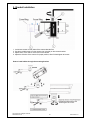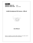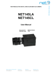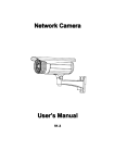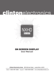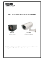
1
SIRZ36-754LP 36x License Plate Zoom Camera with IR Kit SZ36-7540 36x Zoom Camera HI11-TKHBL 11 IR Housing & Bracket Thanks for purchasing our product. Before operating the unit, please read the instructions carefully and keep this manual for future reference. Safety Warnings 1. Read manual carefully before installing the unit. Please read this manual first for correct installation and operation. 2. Never install the camera on a ceiling that cannot hold its weight. The product may fall down and cause damages. 3. Never install the camera near electric or magnetic fields. Install the camera away from TV, radio transmitter, magnet, electric motor, transformer, audio speakers since the magnetic fields generate from above devices would distort the video image. 4. Never install or use the camera in areas exposed to water, oil or gas. The water, oil or gas may result in operation failure, electric shock or fire. Do not use this unit near water-for example, near a bath tub, wash bowl, kitchen sink, or laundry tub, in a wet basement, near a swimming pool, in an unprotected outdoor installation, or any area which is classified as a wet location. 5. Never face the camera toward the sun. Direct sunlight or severe ray may cause fatal damage to sensor and internal circuit. 6. Power Cord Protection. Touching the wet power cord with hands or touching the power cord with wet hands may result in electric shock. Power supply cords should be routed so that they are not likely to be walked on or pinched by items placed upon or against them, playing particular attention to cords and plugs, convenience receptacles, and the point where they exit from the appliance. 7. Attachments Do not use attachment not recommended by the product manufacturer as they may cause hazards. 8. Object and Liquid Entry Never push objects of any kind into this product through openings as they may touch dangerous voltage points or short-out parts that could result in a fire or electric shock, Never spill liquid of any kind onto the product. 9. Do not operate the camera in environments where the temperature, humidity or power source is beyond the specified ones. Use the camera in suitable environments where the temperature is within -10°C~ 50°C and humidity below 90%. The input power source is 12V DC. Copyright 2010. All Rights Reserved. www.okinausa.com -2- REV122010-V17 10. Cleaning Unplug the unit from the outlet before cleaning. Do not use liquid cleaners or aerosol cleaners. Use a damp cloth for cleaning. 11. Never disassemble the camera nor put impurities in it. Disassembly or impurities may result in trouble or fire. 12. Stop using when the product emits smoke or abnormal heat. 13. Servicing Do not attempt to repair this unit yourself as opening or removing covers may expose you to dangerous voltage or other hazards. Refer all servicing to qualified service personnel. 14. Retain Instructions The safety and operating instructions should be retained for future reference. Warranty OKINA USA products are covered under warranty for one year from the date of purchase. The warranty will automatically be voided if any of the following occurs: 1. Camera sticker is removed If the camera sticker is removed, we will not be able to confirm any information regarding when and where the product was purchased. We have no other way to verify the purchase record without the serial number on the camera sticker; therefore, it should not be removed. 2. Camera is modified in any way If the camera is scratched, damaged, or modified in a manner not described in this manual, the warranty will be voided immediately. It is the customer’s responsibility to keep the camera in good condition. 3. Video or power cable is cut The video cable and the power cable should not be tampered with. Cutting or modifying of the cables will result in termination of the warranty. Notice: The information in this manual was current when published. The manufacturer reserves the right to revise and improve its products. All specifications are therefore subject to change without notice. Copyright 2010. All Rights Reserved. www.okinausa.com -3- REV122010-V17 Table of Contents 1 2 3 4 5 5 Product Overview……….………………..………………………………..…………….…..4 5 1.1 Main Features.…..…………..………………………………………………………....4 5 1.2 Content List……………………………………………………………………….…….4 6 1.3 Specifications……………..……….………………………………………………..….5 8 Dimension………………………………………………………………………………………6 2.1 Dimension…………….……………………………………………………………………8 9 2.2 Descriptions………………………………………………………………………………… 12 Camera Setup Operations……………………………………………………………………6 12 3.1 Menu Tree……………………………………………………….…………….…....6 13 3.2 Main Menu…………………………...………………………………………………….6 3.3 Submenus of the Main Menu………………………………………………………… 13 14 3.3.1 SYSTEM……………………………………………………………………………..7 15 3.3.2 DISPLAY……………………………………………………………………………..8 16 3.3.3 PRESET……………………………………………………………………………..9 17 3.3.4 CAMERA…………………………………………………………………………...10 17 3.3.4.1 CAMERA – LENS………………………………………………………..11 20 3.3.4.2 CAMERA - IMAGE………….........................................................…..13 23 3.3.5 ALARM………..........................................................................................…..15 3.3.6 REBOOT.................................................................................................……..23 24 3.3.7 Control via RS-485.............................................................................................. 25 3.3.8 EXIT……........................................................................................................... Housing & Bracket External Power Input Connection…………….…….................. 25 Bracket Installation………………………………………………………………...............26 Copyright 2010. All Rights Reserved. www.okinausa.com -4- REV122010-V17 1. Product Overview SIRZ36-754LP is an integration of a powerful 36x License Plate Zoom Camera, SZ36-7540, plus an 11 IR Housing and Bracket, HI11-TKHBL. The camera is built with 1/4" Sony Exview HAD CCD. Featured with 36x optical auto focus, this camera reproduces sharp and clear images whether zooming-in or zooming-out. 1.1a Main Features for SZ36-7540 Camera: 1/4" Sony Exview HAD CCD, Sony HQ-1 DSP 36x Optical Auto Focus / Auto Iris Zoom Lens Color: 540 TVL; B&W: 560 TVL 0.7 Lux @ F1.6 (30 IRE) Multi-language OSD Setting Menu Mechanical IR Cut Filter (ICR) / Infrared Compensation Auto / Ext / Schedule Day & Night Mode Privacy Zone Masking / Alarm Function Timer Clock; RS485 Interface (Pelco-D, Pelco P) 12V DC, 4.5W 1.1b Main Features for HI11-TKHBL IR Housing & Bracket: 11 Super Power IR LED, 6pc x 25° / 5pc x 45° IR Distance up to 395ft / 120m User Adjustable IR LED Intensity (VR), Factory Default 80% Fully-Cable Managed Bracket Uses professional rust-proof stainless steel screws IP66 Rating; Heater & Blower 24V AC, 60VA, Power Ready Plug for 12V DC Camera See page 7 for details. 1.2 Content List One (1) SIRZ36-754LP camera with IR housing & bracket One (1) Main Accessories Pack Three (3) Rust-proof Stainless Steel Wall Screws Three (3) Rust-proof Stainless Steel Mounting Screws Three (3) Stainless Steel Washers Three (3) Plastic Washers One (1) Allen Wrench One (1) Secondary Accessories Pack Three (3) Screw-on Connectors One (1) Rubber Pad One (1) Rust-proof Stainless Steel Camera Screw One (1) Plastic Washer One (1) User’s manual * For any returns, please include all components listed above with original packaging in Resalable Condition. There is Absolutely No Returns if any component is missing/damaged or if any cable is cut/tampered with. Copyright 2010. All Rights Reserved. www.okinausa.com -5- REV122010-V17 1.3 Specifications Kit P.I.C. L-812 Model TV System Kit Dimension SIRZ36-754LP SIRZ36-754LPP NTSC PAL 16.07.87”(L) x 4.33”(W) x 4.53”(H) / 200mm(L) x 110mm(W) x 115mm(H) Weight 8.23 lbs / 3730g (w/out bracket) Model SZ36-7540 SZ36-7540P NTSC PAL TV System 1/4 Sony Exview HAD CCD Image Sensor Total Pixels Resolution ; DSP Minimum Illumination 410,000 Pixels Color: 0.7 Lux @ F1.6 (30 IRE), B&W: 0.1 Lux @ F1.6 (30 IRE) 1.0Vp-p Composite, 75Ω; Y/C More than 50dB Signal to Noise Ratio (ICR) 470,000 Pixels Color: 540 TVL, B&W: 560 TVL ; SONY HQ-1 Video Output Mechanical IR Cut Filter ; 12.26 lbs / 5560g (with bracket) IR cut filter removable, Lux level adjustable, 12 steps Color / B&W / Auto / External / Schedule Day & Night Mode INTERNAL / EXTERNAL (V-Lock) Synchronization System 1/60 Sec., 1/100 Sec., 1/150 Sec., 1/200 Sec., 1/250 Sec., 1/300 Sec., Automatic Electronic Shutter 1/350 Sec., 1/400 Sec., 1/450 Sec., 1/500 Sec., 1/600 Sec., 1/700 Sec., 1/800 Sec., 1/900 Sec., 1/1000 Sec., 1/1300 Sec., 1/1700 Sec., 1/2000 Sec., 1/2500 Sec., 1/3200 Sec., 1/4000 Sec., 21Steps White Balance Camera ATW / Auto / One Push / Manual / 3200K / 6300K Back Light Compensation ON / OFF Flickerless ON / OFF Auto Gain Control Language Auto / Manual (-3 to 28dB, 16x2dB steps) English, Traditional Chinese, Simplified Chinese, Japanese Negative / Mirror / B&W Picture Effects ON / OFF (8 Zones) Privacy Zone Masking PELCO P / PELCO D Camera Control Interface Alarm In, Alarm Out Alarm Function YY/MM/DD Timer Clock Focusing System Min. Working Distance Angle of View Lens Power Input ; Consumption Operating Temperature ; Humidity Storage Temperature ; Humidity Dimensions Real time AF/ One push AF/ Manual / Infrared Compensation 35mm (Wide end) to 1,500mm (Tele end) o o o 36x optical zoom f3.4mm(Wide)~122.4mm(Tele), F1.6 to F4.5 12V DC +10% ; 4.5W (Motor Inactive), 5.8W (Motor Active) 14°F~122°F / -10°C~+50°C ; 80% RH Max. -4°F~140°F / -20°C~+60°C ; 20%~90% RH 2.28”(W) x 2.42”(H) x 4.33”(L) / 57.8(W)×61.6(H)×110(L) mm 0.51 lbs Weight Copyright 2010. All Rights Reserved. www.okinausa.com o H: 57.8 (Wide) ~1.7 (Tele) / V: 43.7 (Wide) ~1.3 (Tele) -6- / 230g REV122010-V17 Model HI11-TKHBL LED Quantity & Beam Angle 11 Super Power IR LEDs, 6pc x 25° / 5pc x 45° IR Wave Length & Distance 850nm ; 395ft / 120m Auto Light Sensor Control IR Light On / Off IR Housing & Bracket Heater Control 18C / 64F (on); 28C / 82F (off) Blower Control 35C / 95F (on); 25C / 77F (off) IP Rating IP66 Temper Glass Thickness 4mm Mounting Bracket Full-Cable Management Construction Die-Cast Aluminum Alloy Ivory Powder Stove Coating Required Power / 24V AC (+/-10%), 60VA Transformer * 16.0W Power Consumption Dimension Camera Space Weight 16.07.87”(L) x 4.33”(W) x 4.53”(H) / 200mm(L) x 110mm(W) x 115mm(H) 16.73”(L) x 6.30”(W) x 6.50”(H) / 425mm(L) x 160mm(W) x 165mm(H) 7.72 lbs / 3500g (w/out bracket) ; 11.75 lbs / 5330g (with bracket) * Power supply / transformer not included NOTE 1: IR light distances are entirely dependant upon environmental site conditions and the location at which the unit is situated. The type of camera being used is also very important. NOTE 2: Factory default for the IR LED activation level is 80%. If there is not enough IR light, adjust the VR level to maximum 100%. Please see #17 in the Part Description section on page 1. Copyright 2010. All Rights Reserved. www.okinausa.com -7- REV122010-V17 2. Dimension 2.1a Camera Dimension 比例 485+ 485DNO DNI VRI GND + 2.1b Housing & Bracket Dimension Bracket (on left): Max Load: 3500g Material: Die-cast aluminum alloy with light ivory powder coated and stove finish Scan Angle: 180° Tilt Angle: 90° Net Weight: 900g Fixing: 3 Screws with bushings Copyright 2010. All Rights Reserved. www.okinausa.com 8 REV122010-V17 2.2a Camera Descriptions 485+ 485DNO DNI VRI GND + Video Connector This is an output for BNC connection to a video monitor, etc (75Ω). Setting Button SETUP button UP & DOWN button LEFT & RIGHT button Communication Connector 1. RS485+ 2. RS4853. Day & Night Output 4. Day & Night External Input 5. V Lock Pulse Input 6. Ground S-Video output terminal Separate Y(brightness) and C (Color) signal are outputs from this terminal to obtain better video quality at a video monitor. 1. C signal: 0.3V (p-p), 75Ω, unbalance 2. Y signal: 1.0V (p-p), 75Ω, unbalance, negative synchronizing 3. C signal Ground 4. Y signal Ground Power Input Indicator Light When the camera is connected to a power source, the indicator light will be on. Power Input Terminal Connect the power input of 12V DC. RS-485 Terminal Resistor Switch Set the first and the last equipments terminal resistor as ON. As for the rest parallel connection equipment in the middle set as OFF to keep the best transmitted status. Copyright 2010. All Rights Reserved. www.okinausa.com 9 REV122010-V17 2.2b Housing & Bracket Descriptions Copyright 2010. All Rights Reserved. www.okinausa.com 10 REV122010-V17 1. Lens Cap with Heater 2. Temper Glass 3. IR LED: 7pcs or 11pcs Super Power IR LED with Refractor 4. IR Board and IR Board Bracket 5. Universal IR Control Circuit Board: When the IR light turns on, it automatically adjusts the color to monochromatic through the universal IR control circuit. 6. Camera Bracket 7. Power Supply Unit: 24V AC input, 60VA 8. Blower and Blower Bracket 9. Thermostat Switch 10. Video Input BNC Male Connector: Connect to camera 11. Video Out BNC Female Connector: Connect to monitor 12. Terminal Board 13. Fuse Holder: With 250V / 3.15A fuse 14. AC IN Terminal block: 24V AC external power input 15. OUTPUT_1 Terminal block: Plug and fix the power cable of camera 16. OUTPUT_2 Terminal block: To power supply unit 17. VR: Adjust VR to set Infrared LED activation level Factory default 80% -- If there is not enough IR light, adjust the level to maximum 100% 18. Thermostat Switch: Turns on at 35C / 95F and turns off at 25C / 77F for Blower 19. Ground wire: To top cover 20. 12V DC Power-in jack: To camera / center+, outerWhen using a camera which requires a 24V AC power input, please run a separate power line to the camera 21. Flying Bare Lead Wire: When the wire is not in use, cover it with the screw-on connector or tape the tip with tape to prevent damages caused by the bare lead wire. Copyright 2010. All Rights Reserved. www.okinausa.com 11 REV122010-V17 3. Camera Setup Operations 3.1 Menu Tree MAIN MENU SYSTEM LANGUAGE CAMERA TITLE CAMERA ID BAUD RATE PROTOCOL FIRMWARE RESTORE DISPLAY CARMERA ID CAMERA TITLE PRESET TITLE DATE/TIME ZOOM RATIO ALARM ALARM MESSAGE PRESET PRESET NO. POSI SAVE DELETE TITLE PAUSE TIME CAMERA LENS IMAGE FOCUS EXPOSURE MODE WHITEBALANCE WHITE IRIS BRIGHTNESS SHARPNESS ZOOM SPD BACKLIGHT FOCUS SPD FLC DAY/NIGHT AGC NIGHT LIGHT SYNC MIRROR POS./NEG. PRIVACY MASK ALARM IN SWITCH IN MODE OUT SWITCH OUT TIME REBOOT EXIT Copyright 2010. All Rights Reserved. www.okinausa.com 12 REV122010-V17 3.2 Main Menu MAIN MENU SET SET SET SET SET STARTUP SYSTEM DISPLAY PRESET CAMERA ALARM REBOOT EXIT 3.3 Submenus of the MAIN MENU There’re several submenus of the main menu: SYSTEM, DISPLAY, PRESET, CAMERA, ALARM, and REBOOT. Return to previous page Select RETURN and press the SET button to return to previous page. Close the menu screen To close the menu screen, use the buttons to select EXIT and press the SET button. Enter the engineering menu Press the RIGHT button for 3 seconds to enter the engineering menu to select the suitable camera type. Selections are Camera, Car Plate License Camera, and Module Camera. When the Module Camera is selected, values of CAMERA ID, BAUD RATE, and PROTOCOL can not be changed. Copyright 2010. All Rights Reserved. www.okinausa.com 13 REV122010-V17 3.3.1-SYSTEM LANGUAGE CAMERA ID ENGLISH TRADITIONAL CHINESE SIMPLIFIED CHINESE JAPANESE CAMERA TITLE SET 1~1024 0 1 2 3 4 5 6 7 8 9 AB CDE FGHI J KL M NOP QRST UVWXYZ a b c d e f g h i j k l m n o p q r s t u v w x y z . , : ‘ “ / # * = ( ) < > - - - - - - - - - - - - - --SPACE BACKSPACE POSI COPY OK CANCEL BAUD RATE PROTOCOL FIRMWARE 2400 4800 9600 19200 38400 RESTORE SET PELCO D PELCO P XX.XX CANCEL CONTINUE I. II. LANGUAGE: Set language preference. Selections are ENGLISH TRADITIONAL CHINESE SIMPLIFIED CHINESE JAPANESE CAMERA ID: Camera ID can be set in here. Only numbers 1-1024 can be used. III. CAMERA TITLE: Numbers, letters and symbols can be used for naming the camera title. *Use direction buttons to select the desired character. *Press SET button to confirm each selection. *Use the direction buttons to OK to confirm the setting. *Use the direction buttons to CANCEL to abort the setting. *Select POSI to change the position of the shown camera title. *Select SPACE when a blank / a space is needed. *Select BACKSPACE to clear the precedent character. IV. BAUD RATE: V. VI. VII. Baud Rates can be set here. 2400 4800 9600 19200 38400 PROTOCOL: Select the protocol here. There’re 2 types PELCO D PELCO P FIRMWARE: Please refer to the actual firmware version. RESTORE: Choose CANCEL to exit; once the CONTINUE is selected, all the settings will be restored to the default settings. There’re no default settings for Camera Type, CAMERA ID, BAUD RATE, PROTOCOL and Language; thus, these settings will stay the same even the CONTINUE is selected. Copyright 2010. All Rights Reserved. www.okinausa.com 14 REV122010-V17 3.3.2-DISPLAY CAMERA ID OFF ON CAMERA TITLE PRESET TITLE OFF ON DATE/TIME OFF ON OFF ON DATE / TIME TIME HH:MM:SS DATE YY:MM:DD FORMAT YY:MM:DD RETURN ZOOM RATIO ALARM MESSAGE I. MM:DD:YY DD:MM:YY EXIT OFF ON OFF ON CAMERA ID: Select ON to show the Camera ID on the screen; select OFF to hide the Camera ID from the screen. II. CAMERA TITLE: Select ON to show the Camera Title on the screen; select OFF to hide the Camera Title from the screen. III. PRESET TITLE: Select ON to show the Preset Title on the screen; select OFF to hide the Preset Title from the screen. IV. DATE/TIME: HH: Hour, MM: Minute, SS: Second, YY: Year, MM: Month, DD: Date. *Select ON/OFF to show/hide the Date/Time on the screen. DATE/TIME Adjust: *When ON is selected, Date/Time can be adjusted. *Press SET BUTTON to set up. *Use RIGHT BUTTON to increase the number and LEFT BUTTON to decrease. *Press the SET BUTTON to confirm each adjusted number. FORMAT Adjust: *The Date/Time Format can further be arranged. YY:MM:DD MM:DD:YY DD: MM:YY V. ZOOM RATIO: Select ON to show the Zoom Ratio on the screen; select OFF to hide the Zoom Ratio from the screen. VI. ALARM MESSAGE: Select ON to show the Alarm Message on the screen; select OFF to hide the Alarm Message from the screen. Copyright 2010. All Rights Reserved. www.okinausa.com 15 REV122010-V17 3.3.3-PRESET PRESET NO. 1-256 POSI SET U ZOOM D/L FOCUS R PRESS ENTER CONFIRM SAVE SET DELETE ABOVE ALL TITLE SET OK 0 1 2 3 4 5 6 7 8 9 AB CDE FGHI J KL M NOP QRST UVWXYZ a b c d e f g h i j k l m n o p q r s t u v w x y z . , : ‘ “ / # * = ( ) < > - - - - - - - - - - - - - --- PAUSE TIME I. SPACE BACKSPACE POSI COPY OK CANCEL 0-255 PRESET NO.: Select the to-be-set/desired PRESET NO from 1-256. II. POSI: U ZOOM D/L FOCUS R Press SET while the POSI is highlighted to setup the position. Use UP/DOWN BUTTON to adjust ZOOM and LEFT/RIGHT BUTTON to adjust the FOUCS. III. IV. SAVE: Select SET and press the SET BUTTON to save the settings. DELETE: Select ABOVE or ALL to delete the setting above or to delete every preset settings. V. TITLE: Numbers, letters and symbols can be used for naming the camera title. *Use direction buttons to select the desired character. *Press SET button to confirm each selection. *Use the direction buttons to OK to confirm the setting. *Use the direction buttons to CANCEL to abort the setting. *Select POSI to change the position of the shown camera title. *Select SPACE when a blank / a space is needed. *Select BACKSPACE to clear the precedent character. VI. PAUSE TIME: Pause time can be chosen from 0 to 255 seconds. Copyright 2010. All Rights Reserved. www.okinausa.com 16 REV122010-V17 3.3.4-CAMERA 3.3.4.1-CAMERA-LENS LENS SET FOCUS REAL TIME AF ONE PUSH MANUAL IRIS AUTO MANUAL BRIGHTNESS 1-15 ZOOM SPD 1-15 FOCUS SPD 1-15 DAY / NIGHT COLORB&WAUTOEXT SCHEDULE COLOR B&W AUTO LEVEL 1-10 DLY TIME 1-10 SEC OUTPUT EXTERNAL DAY / NIGHT IN L LEVEL H LEVEL SCHEDULE DAY / NIGHT HH:MM NIGHT / DAY HH:MM NIGHT LIGHT Copyright 2010. All Rights Reserved. www.okinausa.com NORMAL INFRARED 17 REV122010-V17 I. i. LENS: Settings concerning Lens can be set in here. FOCUS: REAL TIME AF: Select REAL TIME AF to detect the ambiance light and to adjust the focus automatically. ONE PUSH: When the zoom is changed with the TELE or the WIDE buttons, it becomes AF Mode. Then, it stops. MANUAL: Select MANUAL to adjust the focus by adding or subtracting the shown setting. ii. IRIS: MANUAL: Select MANUAL adjust the IRIS manually. AUTO: When AUTO is selected, the IRIS will be adjusted automatically. iii. BRIGHTNESS: There’re 1-15 levels: the bigger the number, the brighter the images. the IRIS has set to be manual, this function will be disabled. iv. But if ZOOM SPD: There’re 1-15 levels: the bigger the number, the faster the zoom changing speed will be. v. FOCUS SPD: There’re 1-15 levels: when under the manual mode, the bigger the number, the faster the focus changing speed will be. However, under REAL TIME AF and ONE PUSH Modes, the FOCUS SPD is fixed and can not be adjusted. vi. DAY/NIGHT: COLOR: The COLOR mode. B&W: The BLACK & WHITE mode. AUTO: When AUTO is selected, it will detect the ambient light to change from DAY/COLOR to NIGHT/B&W and vice versa. LEVEL: Select brightness of illumination about changing the day/night mode. The bigger the number, the brighter the images. DELAY TIME: can be chosen from 1 to 10 seconds to delay the switching time (from DAY/Color to NIGHT/B&W time and vise visa.) OUTPUT: Select output level. D&N OUT: It’s the PIN 3 external control connector. OUTPUT L LEVEL D&N OUT SYSTEM H LEVEL COLOR HIGH LOW B&W LOW HIGH (HIGH: 5V; LOW: GND) Copyright 2010. All Rights Reserved. www.okinausa.com 18 REV122010-V17 EXTERNAL: Use the external signal to switch COLOR/B&W. INPUT: Select input level. D&N IN: It’s the PIN 4 external control connector. INPUT SYSTEM D&N IN L LEVEL H LEVEL HIGH COLOR B&W LOW B&W COLOR (HIGH: OPEN or 5V; LOW: GND) SCHEDULE: When SCHEDULE is selected, timing can be set to switch Day/Night Mode. DAY/NIGHT: set the timing to switch from DAY/COLOR to NIGHT/B&W. NIGHT/DAY: set the timing to switch from NIGHT/B&W to DAY/COLOR. vii. NIGHT LIGHT: When IR LED is in use, select INFRARED. When regular illuminator is in use, select NORMAL. Copyright 2010. All Rights Reserved. www.okinausa.com 19 REV122010-V17 3.3.4.2-CAMERA-IMAGE IMAGE SET EXPOSURE MODE MANUAL AUTO AUTO--SHUT SPD 1/250 1/500 1/1000 1/2000 1/4000 1/10000 1/100000 MANUAL-SHUT SPD 1/60 Sec. 1/100 Sec. 1/150 Sec., 1/200 Sec. 1/250 Sec. 1/300 Sec., 1/350 Sec. 1/400 Sec. 1/450 Sec., 1/500 Sec. 1/600 Sec. 1/700 Sec., 1/800 Sec.1/900 Sec. 1/1000 Sec., 1/1300Sec.1/1700Sec.1/2000Sec., 1/2500Sec.1/3200Sec.1/4000Sec. WHITE BALANCE ATW AUTO MWB ONE PUSH 3200K 6300K SHARPNESS BACKLIGHT 0-15 OFF BLC BLC 1~16 Levels FLC AGC SYNC MIRROR POS. / NEG. PRIVACY MASK OFF ON MANUAL AUTO INT LL OFF ON OFF ON SET OFF ON ON AREA SEL 01-08 AREA MODE COLOR GREEN ORANGE BLACK WHITE GRAY BLUE RED PURPLE Copyright 2010. All Rights Reserved. www.okinausa.com 20 REV122010-V17 II. IMAGE i. EXPOSURE MODE: To adjust the shutter speeds. AUTO: Automatic Electronic Shutter MAX SHUT SPD: adjust the maximum shutter speed; shutter will change from 1/50(60) to maximum shutter speed automatically. 1/250 1/500 1/1000 1/2000 1/4000 1/10000 1/100000 MANUAL: Adjust shutter manually. SHUT SPD: adjust shutter speed. 1/60 Sec., 1/100 Sec., 1/150 Sec., 1/200 Sec., 1/250 Sec., 1/300 Sec., 1/350 Sec., 1/400 Sec., 1/450 Sec., 1/500 Sec., 1/600 Sec., 1/700 Sec., 1/800 Sec., 1/900 Sec., 1/1000 Sec., 1/1300 Sec., 1/1700 Sec., 1/2000 Sec., 1/2500 Sec., 1/3200 Sec., 1/4000 Sec., 21Steps ii. WHITE BALANCE 6 different modes to choose from, ATW, AUTO, MWB, ONE PUSH, 3200K or 6300K. ATW (Auto Tracking White Balance): This mode can be used within the color temperature range from 2,500°K to 9,000°K (eg, fluorescent light, outdoor, sodium vapor lamp or inside tunnels). AUTO: This mode computes the white balance value output using color information from the entire screen. It outputs the proper value using the color temperature radiating from a black subject. MWB: (Manual White Balance) MODE: 1~4 RED: select RED to adjust RED gain. BLUE: select BLUE to adjust BLUE gain. ONE PUSH: The ONE PUSH WHITE BALANCE mode is a fixed mode that may be automatically readjusted only at the request of the user. ONE PUSH WHITE BALANCE SETUPS *Press the SET button continually to adjust the WHITE BALANCE. *Release the SET button, and the WHITE BALANCE will be set. *Press the SET button again to exit. 3200K: Indoor 6300K: Outdoor iii. SHARPNESS: The contour of the video image becomes cleaner and more distinguished as the level of SHARPNESS increases. If the level goes up extremely, it may affect the video image and cause noise. The available range is 0~15. Restart the camera is required to save the new SHARPNESS settings. After the settings are done, the camera will restart automatically. Copyright 2010. All Rights Reserved. www.okinausa.com 21 REV122010-V17 iv. BACKLIGHT: Even when there’s a massive backlight behind the object, bright images of the background and the object can still be obtained by using the BACKLIGHT function. Levels: 1~16. v. FLC: Flicker can be eliminated by setting FLC to be ON. vi. AGC (AUTO GAIN CONTROL) AUTO: when AUTO is selected, the maximum gain is 26dB. MANUAL: when MANUAL is selected, the maximum gain can be adjusted manually, adjusting range from -3 to 28dB. The more the level of gain increases, the brighter the screen and the level of noise increases. vii. SYNC: INT: Internal synchronization LL: External line-lock synchronization: when LL is selected, press the SET BUTTON to confirm. The phase can be set from 0 to 359. viii. MIRROR: When ON is selected, images will be horizontal rotated. ix. POS./NEG.: Negative/Positive Reversal. Select ON or OFF to enable or disable this function. x. PRIVACY MASK: AREA SEL: There’re 1~8 masking areas to choose from. *Press the LEFT/RIGHT buttons to choose the desired areas 1-8. AREA MODE: To select the area to be masked or not. ON or OFF. Selected area setups: *Press the SET button to enter the chosen area to do the settings. *Press UP/DOWN to zoom in or zoom out. Size of the selected area: *Press the SET button to set the size of the masking area. *Use the UP/DOWN buttons to select TOP/BOTTOM/LEFT/RIGHT. *Use the LEFT/RIGHT buttons to shrink or to enlarge the masking area size. *Press the SET button to exit. COLOR:There’re 8 kinds of colors to choose from, GREEN, ORANGE, BLACK, WHITE, GRAY, BLUE, RED, PURPLE. Copyright 2010. All Rights Reserved. www.okinausa.com 22 REV122010-V17 3.3.5-ALARM OFF ON IN SWITCH IN MODE OUT SWITCH OUT TIME NC NO OFF ON 100ms 200ms 300ms 500ms 1000ms 2000ms 3000ms 5000ms I. IN SWITCH: Select ON to set the alarm or OFF to cancel the alarm. II. IN MODE: NO: NORMAL OPEN; NC: NORMAL CLOSE. III. OUT SWITCH: Select ON or OFF, to output the alarm or not. IV. OUT TIME: There’re 8 length of time to choose from: 100ms 200ms 300ms 500ms 1000ms 2000ms 3000ms5000ms 3.3.6-REBOOT REBOOT I. STARTUP Restart the camera. Copyright 2010. All Rights Reserved. www.okinausa.com 23 REV122010-V17 3.3.7-Control via RS-485 I. Pairing with Camera Keyboard Controller The Protocol between Camera and the Keyboard Controller should be the same to ensure a successful communication. Please refer to the 3.3.1 System for further communication settings. 485+ 485DNO DNI VRI GND + MZC-EX1000A Copyright 2010. All Rights Reserved. www.okinausa.com KeyBoard RS485+ ← RS485Tx+ RS485- ← RS485Tx- 24 REV122010-V17 II. Using Camera Keyboard Controller The operation methods may vary from model to model. *the 95th Preset Point for MENU, please press Call the 95th or the 95th Preset or the 95th Call *Memorize 95th Preset Point to Preset the 95th, please press the 95th the 95th Add the 95th Preset (Press for several seconds.) the 95th Preset *Selections: Please move the control stick upward/downward or use the direction buttons to choose the selection. *Adjust Value: Please use the Left and Right buttons to change the values of each selection. Press the IRIS OPEN or to enter the sub menu. *Exit Select Exit and press the IRIS OPEN or to return to the previous page or leave the menu. 3.3.8-EXIT EXIT I. Select EXIT to leave the MENU. 4. Housing & Bracket External Power Input Connection NOTE: When using two-cord power cable, please connect them to “Live” and “Neutral.” Copyright 2010. All Rights Reserved. www.okinausa.com 25 REV122010-V17 5. Bracket Installation 1. 2. 3. 4. Loosen two screws on both sides of the camera bracket first. Use the provided screw to fix the camera (not included) on the camera bracket. Adjust zoom, focus and iris of the lens on the camera. Adjust the direction of the camera for proper position, after finished tighten all screws. How to install cables through the mounting bracket: Copyright 2010. All Rights Reserved. www.okinausa.com 26 REV122010-V17