1
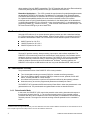
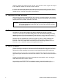
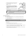
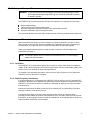
PARSTAT 2273
Potentiostat/Galvanostat
Hardware User’s Manual
223685B / 1104
Printed in USA
$GYDQFHG0HDVXUHPHQW7HFKQRORJ\,QF
a/k/a Princeton Applied Research, a subsidiary of AMETEK®, Inc.
:$55$17<
Princeton Applied Research* warrants each instrument of its own manufacture to be free of defects in material and
workmanship. Obligations under this Warranty shall be limited to replacing, repairing or giving credit for the purchase price, at
our option, of any instrument returned, shipment prepaid, to our Service Department for that purpose within ONE year of
delivery to the original purchaser, provided prior authorization for such return has been given by an authorized representative of
Princeton Applied Research.
This Warranty shall not apply to any instrument, which our inspection shall disclose to our satisfaction, to have become
defective or unworkable due to abuse, mishandling, misuse, accident, alteration, negligence, improper installation, or other
causes beyond our control. This Warranty shall not apply to any instrument or component not manufactured by Princeton
Applied Research. When products manufactured by others are included in Princeton Applied Research equipment, the original
manufacturer's warranty is extended to Princeton Applied Research customers.
Princeton Applied Research reserves the right to make changes in design at any time without incurring any obligation to install
same on units previously purchased.
THERE ARE NO WARRANTIES THAT EXTEND BEYOND THE DESCRIPTION ON THE FACE HEREOF. THIS WARRANTY
IS IN LIEU OF, AND EXCLUDES ANY AND ALL OTHER WARRANTIES OR REPRESENTATIONS, EXPRESSED, IMPLIED
OR STATUTORY, INCLUDING MERCHANTABILITY AND FITNESS, AS WELL AS ANY AND ALL OTHER OBLIGATIONS OR
LIABILITIES OF PRINCETON APPLIED RESEARCH, INCLUDING, BUT NOT LIMITED TO, SPECIAL OR CONSEQUENTIAL
DAMAGES. NO PERSON, FIRM OR CORPORATION IS AUTHORIZED TO ASSUME FOR PRINCETON APPLIED
RESEARCH ANY ADDITIONAL OBLIGATION OR LIABILITY NOT EXPRESSLY PROVIDED FOR HEREIN EXCEPT IN
WRITING DULY EXECUTED BY AN OFFICER OF PRINCETON APPLIED RESEARCH.
6+28/' <285 (48,30(17 5(48,5( 6(59,&(
A. Contact the Customer Service Department (865-482-4411) or your local representative to discuss the problem. In many
cases it will be possible to expedite servicing by localizing the problem.
B. If it is necessary to send any equipment back for service, we need the following information.
1. Model number and serial number.
5. Your telephone number and extension.
2. Your name (instrument user).
6. Symptoms (in detail, including control settings).
3. Your address.
7. Your purchase order number for repair charges (does not apply to
repairs in warranty).
4. Address to which the instrument
should be returned.
8. Shipping instructions (if you wish to authorize shipment by any
method other than normal surface transportation).
C. U.S. CUSTOMERS — Ship the equipment being returned to:
Advanced Measurement Technology, Inc.
801 S. Illinois Avenue
Oak Ridge, TN 37831
ATTN: Customer Service
PHONE: 865-482-4411
FAX:
865-483-2133
D. CUSTOMERS OUTSIDE OF U.S.A. — To avoid delay in customs clearance of equipment being returned, please contact the
factory or the nearest factory distributor for complete shipping information.
Copyright © 2004, Advanced Measurement Technology, Inc. All rights reserved.
*Princeton Applied Research is a registered trademark of Advanced Measurement Technology, Inc., an ISO9001:2000 certified company. All
other trademarks used herein are the property of their respective owners.
ii
7$%/(2)&217(176
Safety Instructions and Symbols . . . . . . . . . . . . . . . . . . . . . . . . . . . . . . . . . . . . . . . . . . . . . . . . . . . . . . . . . . . . . . . v
Cleaning Instructions . . . . . . . . . . . . . . . . . . . . . . . . . . . . . . . . . . . . . . . . . . . . . . . . . . . . . . . . . . . . . . . . . . . . . . . . v
1. INTRODUCTION . . . . . . . . . . . . . . . . . . . . . . . . . . . . . . . . . . . . . . . . . . . . . . . . . . . . . . . . . . . . . . . . . . . . . . . .
1.1. Applications . . . . . . . . . . . . . . . . . . . . . . . . . . . . . . . . . . . . . . . . . . . . . . . . . . . . . . . . . . . . . . . . . . . . . . . . .
1.2. Booster Interface . . . . . . . . . . . . . . . . . . . . . . . . . . . . . . . . . . . . . . . . . . . . . . . . . . . . . . . . . . . . . . . . . . . . .
1.3. Hardware and Software . . . . . . . . . . . . . . . . . . . . . . . . . . . . . . . . . . . . . . . . . . . . . . . . . . . . . . . . . . . . . . .
1.4. Potentiostatic Circuitry . . . . . . . . . . . . . . . . . . . . . . . . . . . . . . . . . . . . . . . . . . . . . . . . . . . . . . . . . . . . . . . .
1.4.1. Potentiostatic Mode . . . . . . . . . . . . . . . . . . . . . . . . . . . . . . . . . . . . . . . . . . . . . . . . . . . . . . . . . . . . .
1.4.2. Galvanostatic Mode . . . . . . . . . . . . . . . . . . . . . . . . . . . . . . . . . . . . . . . . . . . . . . . . . . . . . . . . . . . . .
1.5. Polarity Convention . . . . . . . . . . . . . . . . . . . . . . . . . . . . . . . . . . . . . . . . . . . . . . . . . . . . . . . . . . . . . . . . . . .
1.6. Inspecting Your New Instrument . . . . . . . . . . . . . . . . . . . . . . . . . . . . . . . . . . . . . . . . . . . . . . . . . . . . . . . . .
1.7. Maintenance, Service, and Support . . . . . . . . . . . . . . . . . . . . . . . . . . . . . . . . . . . . . . . . . . . . . . . . . . . . . .
1.8. About This Manual . . . . . . . . . . . . . . . . . . . . . . . . . . . . . . . . . . . . . . . . . . . . . . . . . . . . . . . . . . . . . . . . . . .
1
1
2
2
2
2
3
3
4
4
4
2. SAFETY AND COMPONENT PLACEMENT . . . . . . . . . . . . . . . . . . . . . . . . . . . . . . . . . . . . . . . . . . . . . . . . . . .
2.1. Power Cord . . . . . . . . . . . . . . . . . . . . . . . . . . . . . . . . . . . . . . . . . . . . . . . . . . . . . . . . . . . . . . . . . . . . . . . . .
2.2. Line Voltage and Fusing . . . . . . . . . . . . . . . . . . . . . . . . . . . . . . . . . . . . . . . . . . . . . . . . . . . . . . . . . . . . . . .
2.2.1. Selecting the Line Voltage . . . . . . . . . . . . . . . . . . . . . . . . . . . . . . . . . . . . . . . . . . . . . . . . . . . . . . . .
2.2.2 Replacing the Fuses . . . . . . . . . . . . . . . . . . . . . . . . . . . . . . . . . . . . . . . . . . . . . . . . . . . . . . . . . . . . .
2.3. Defects and Abnormal Stresses . . . . . . . . . . . . . . . . . . . . . . . . . . . . . . . . . . . . . . . . . . . . . . . . . . . . . . . . .
2.4. Component Placement . . . . . . . . . . . . . . . . . . . . . . . . . . . . . . . . . . . . . . . . . . . . . . . . . . . . . . . . . . . . . . . .
2.4.1. Ventilation . . . . . . . . . . . . . . . . . . . . . . . . . . . . . . . . . . . . . . . . . . . . . . . . . . . . . . . . . . . . . . . . . . . .
2.4.2. Radio Frequency Interference . . . . . . . . . . . . . . . . . . . . . . . . . . . . . . . . . . . . . . . . . . . . . . . . . . . . .
2.4.3. Transient Sensitivity . . . . . . . . . . . . . . . . . . . . . . . . . . . . . . . . . . . . . . . . . . . . . . . . . . . . . . . . . . . . .
5
5
5
5
6
7
7
7
7
8
3. INSTALLATION . . . . . . . . . . . . . . . . . . . . . . . . . . . . . . . . . . . . . . . . . . . . . . . . . . . . . . . . . . . . . . . . . . . . . . . .
3.1. Enabling the USB Port on Your PC . . . . . . . . . . . . . . . . . . . . . . . . . . . . . . . . . . . . . . . . . . . . . . . . . . . . .
3.2. Connectors and Indicators . . . . . . . . . . . . . . . . . . . . . . . . . . . . . . . . . . . . . . . . . . . . . . . . . . . . . . . . . . . .
3.2.1. Rear Panel . . . . . . . . . . . . . . . . . . . . . . . . . . . . . . . . . . . . . . . . . . . . . . . . . . . . . . . . . . . . . . . . . . .
3.2.1.1. Connectors . . . . . . . . . . . . . . . . . . . . . . . . . . . . . . . . . . . . . . . . . . . . . . . . . . . . . . . . . . . .
3.2.1.2. Booster Interface . . . . . . . . . . . . . . . . . . . . . . . . . . . . . . . . . . . . . . . . . . . . . . . . . . . . . . .
3.2.2. Front Panel . . . . . . . . . . . . . . . . . . . . . . . . . . . . . . . . . . . . . . . . . . . . . . . . . . . . . . . . . . . . . . . . . . .
3.2.2.1. Connectors . . . . . . . . . . . . . . . . . . . . . . . . . . . . . . . . . . . . . . . . . . . . . . . . . . . . . . . . . . . .
3.2.2.2. Controls . . . . . . . . . . . . . . . . . . . . . . . . . . . . . . . . . . . . . . . . . . . . . . . . . . . . . . . . . . . . . .
3.2.2.3. Indicators . . . . . . . . . . . . . . . . . . . . . . . . . . . . . . . . . . . . . . . . . . . . . . . . . . . . . . . . . . . . .
3.3. Connecting to the PC and Cell . . . . . . . . . . . . . . . . . . . . . . . . . . . . . . . . . . . . . . . . . . . . . . . . . . . . . . . . .
3.3.1. Connecting to the PC . . . . . . . . . . . . . . . . . . . . . . . . . . . . . . . . . . . . . . . . . . . . . . . . . . . . . . . . . . .
3.3.1.1. Installing the USB Driver . . . . . . . . . . . . . . . . . . . . . . . . . . . . . . . . . . . . . . . . . . . . . . . . .
3.3.2. Connecting the Cell . . . . . . . . . . . . . . . . . . . . . . . . . . . . . . . . . . . . . . . . . . . . . . . . . . . . . . . . . . . .
11
11
11
11
11
12
13
13
14
14
15
15
15
15
4. SPECIFICATIONS AND PINOUTS . . . . . . . . . . . . . . . . . . . . . . . . . . . . . . . . . . . . . . . . . . . . . . . . . . . . . . . . .
4.1. Electrical Specifications, Potentiostatic Circuitry . . . . . . . . . . . . . . . . . . . . . . . . . . . . . . . . . . . . . . . . . . .
4.1.1. Power Amplifier . . . . . . . . . . . . . . . . . . . . . . . . . . . . . . . . . . . . . . . . . . . . . . . . . . . . . . . . . . . . . . .
4.1.2. Differential Electrometer . . . . . . . . . . . . . . . . . . . . . . . . . . . . . . . . . . . . . . . . . . . . . . . . . . . . . . . .
4.1.3. iR Compensation . . . . . . . . . . . . . . . . . . . . . . . . . . . . . . . . . . . . . . . . . . . . . . . . . . . . . . . . . . . . . .
4.1.4. Current Measurement . . . . . . . . . . . . . . . . . . . . . . . . . . . . . . . . . . . . . . . . . . . . . . . . . . . . . . . . . .
4.1.5. Potential/Current Control . . . . . . . . . . . . . . . . . . . . . . . . . . . . . . . . . . . . . . . . . . . . . . . . . . . . . . . .
4.1.6. Impedance Specification . . . . . . . . . . . . . . . . . . . . . . . . . . . . . . . . . . . . . . . . . . . . . . . . . . . . . . . .
4.2. Physical and Power Specifications . . . . . . . . . . . . . . . . . . . . . . . . . . . . . . . . . . . . . . . . . . . . . . . . . . . . . .
4.3. Standard Environmental Conditions . . . . . . . . . . . . . . . . . . . . . . . . . . . . . . . . . . . . . . . . . . . . . . . . . . . . .
17
17
17
17
17
17
17
18
18
18
iii
4.4. AUXILIARY INTERFACE Pinouts . . . . . . . . . . . . . . . . . . . . . . . . . . . . . . . . . . . . . . . . . . . . . . . . . . . . . . . 18
iv
PARSTAT 2273 Hardware User’s Manual
6DIHW\,QVWUXFWLRQVDQG6\PEROV
This manual contains up to three levels of safety instructions that must be observed in order to avoid personal
injury and/or damage to equipment or other property. These are:
DANGER
Indicates a hazard that could result in death or serious bodily harm if the safety instruction is not
observed.
WARNING
Indicates a hazard that could result in bodily harm if the safety instruction is not observed.
CAUTION
Indicates a hazard that could result in property damage if the safety instruction is not observed.
In addition, the following symbols may appear on the product:
DANGER–High Voltage!
ATTENTION–Refer to Manual
Please read all safety instructions carefully and make sure you understand them fully
before attempting to use this product.
&OHDQLQJ,QVWUXFWLRQV
WARNING Using this instrument in a manner not specified by the manufacturer may impair the protection
provided by the instrument.
To clean the instrument exterior:
Unplug the instrument from all voltage sources.
Remove loose dust on the outside of the instrument with a lint-free cloth.
Remove remaining dirt with a lint-free cloth dampened in a general-purpose detergent and water solution.
Do not use abrasive cleaners.
CAUTION
To prevent moisture inside of the instrument during external cleaning, use only enough liquid
to dampen the cloth or applicator.
Allow the instrument to dry before reconnecting the power cord.
TABLE OF CONTENTS
v
vi
PARSTAT 2273 Hardware User’s Manual
,1752'8&7,21
The Princeton Applied Research PARSTAT 2273 offers compliance voltage up to ±100 V
(available at the counter electrode), ±10-V scan ranges, a ±2-A current range, the ability to make
electrochemical impedance spectroscopy (EIS) measurements from 10 µHz to 1 MHz, and a
design that will sustain long-term, heavy-load operation. The 2273 connects to your PC or laptop
via Universal Serial Bus (USB), and uses one of our Electrochemistry PowerSuite™ family of
electrochemistry software modules — there are no user controls on the instrument itself.
Calibration, operation, and experimental procedures are covered in the Electrochemistry
PowerSuite HTML Help Manual, available on the software’s Help menu.
Major Features
2 A current maximum (20 A boosted)
100 V compliance
1.2 fA current resolution
>1013 input impedance (typical)
<5 pF of capacitance (typical)
10 µHz to 1 MHz built-in analyzer for impedance
1.1. Applications
Research Electrochemistry — From determining the kinetics of an electron-transfer process,
to developing new and improved materials via unique electrodeposition or electrosynthesis
techniques, the PARSTAT 2273 was designed with the flexibility and capability required by
today's electrochemical researcher. Whether you are measuring a microelectrode, rotating disk
electrode, mercury electrode, or quartz crystal resonator, the 2273 supports the wide array of
electrodes used in a modern electrochemistry research lab.
Corrosion — The 2273 is ideal for corrosion research. Whether you are measuring rebar in
concrete or titanium in Ringer's solution, the 2273 was designed to address your application.
Our PowerCORR™ Corrosion Measurement Software and PowerSINE EIS package
complement the 2273's impressive specifications to create the ultimate tool for any corrosion
lab. Are you working with large electrodes or resistive media? The 2273's 100 V compliance
voltage takes care of that. Studying a new corrosion inhibitor or coating technology? Femtoamp
current resolutions and >1013 input impedance make even the toughest EIS measurements
seem routine.
Sensors — For potentiometric sensors (such as ion-selective electrodes and coated wire
electrodes) and amperometric sensors (gas sensors, thin film microelectrodes, and chemically
modified electrodes), the 2273 provides current sensitivities that can surpass the requirements
of the most demanding measurement parameters, with a pA current range and fA resolution.
High compliance voltage allows for the growth of thin film electrodes and nanodeposition.
Biosensor development and analysis relies on techniques that are contained within the
PowerCV® cyclic voltammetry, PowerSTEP® chronoamperomtry/chronopotentiometry, and
PowerPULSE™ electroanalytical software packages.
Fuel Cells and Batteries — For many years, Princeton Applied Research potentiostats/
galvanostats have been used in the development of new energy sources. From the early stages
of battery development to the charge/discharge experiments on the final product, the 2273 has
the current measurement range to address the challenges posed in developing the next
generation of batteries. Fuel cells offer a cleaner energy source for the future, and the 2273
helps bring that technology to market: Use EIS to examine the impedance of the PEM at
different humidity levels, perform I/V curves on solid oxide fuel cells (SOFCs), or run CVs on
1
direct methanol fuel cell (DMFC) assemblies. The 2273 together with the entire Electrochemistry
PowerSuite package has the potential to take your research to the next level.
Biomedical Applications — The 2273 exceeds the requirements for potentiostats/galvanostats
as described in ASTM F2129, Standard Test Method for Conducting Cyclic Potentiodynamic
Polarization Measurements to Determine the Corrosion Susceptibility of Small Implant Devices.
For implant biocompatibility studies, the most common methods involve DC corrosion
techniques such as cyclic potentiodynamic polarization for the determination of the breakdown
or critical pitting potential (Eb), the corrosion or open circuit potential (Ecorr), the repassivation or
protection potential (Ep), corrosion current (Icorr) and corrosion rates based on Tafel analysis. The
2273 and PowerCORR give you all of these tools.
1.2. Booster Interface
Using the 2273 with one of our current booster options provides you with a seamless interface
for our Electrochemistry PowerSuite software. When a booster option is connected to the 2273,
the software autoscales the data. The 2273 has three current booster options to choose from:
8A/2273 option for 8 A, 50 V
10A/2273 option for 10 A, 20 V
20A/2273 option for 20 A, 20 V
1.3. Hardware and Software
The host PC provides memory, data processing, input-output, and interface capabilities. The
PARSTAT 2273 electronically controls the measurement under direction of the software and the
parameter values you enter from the host computer. The PARSTAT 2273 is fully compatible with
our Electrochemistry PowerSuite family of electrochemistry research and development tools.
While the software operates under all 32-bit Microsoft® Windows® operating systems, the
PARSTAT 2273 requires a USB interface and runs only under Windows 98 SE, 2000, and XP.1
1.4. Potentiostatic Circuitry
The potentiostatic section of the PARSTAT 2273 circuitry includes:
Two 16-bit digital-to-analog converters (DACs) for versatile waveform generation.
Four 16-bit analog-to-digital converters (ADCs) to measure current, potential, SYNC ADC
INPUT, and the potential for current interrupt.
An onboard microprocessor to perform the experiment defined by the operating software.
Onboard memory to store the programmed parameters and data point values.
The PARSTAT 2273 operates with Electrochemistry PowerSuite in either the potentiostatic or the
galvanostatic mode. The potentiostatic and galvanostatic modes are described below.
1.4.1. Potentiostatic Mode
In this mode, the PARSTAT 2273 controls the potential at the working electrode with respect to
the reference electrode (see Fig. 1). The counter electrode is driven to the potential required
(consistent with the ±100 V compliance of the control amplifier) to establish the desired working
electrode potential. The range over which the working electrode potential can be controlled is
±10 V.
1
Windows 95 does not support USB internally, but some USB drivers have been made as additions to Windows 95. These USB drivers do not
have complete support for the USB port and do not work with PARSTAT instruments.
2
PARSTAT 2273 Hardware User’s Manual
Fig. 1. Potentiostat-Mode Block Diagram.
1.4.2. Galvanostatic Mode
In galvanostatic operation, the PARSTAT 2273 controls the current between the counter and
working electrodes at the specified fraction of the selected current range (up to the maximum of
100% the current range; see Fig. 2).
The counter electrode is driven to the potential required (consistent with the ±100 V compliance of
the control amplifier) to establish the desired cell current. The reference electrode is not used in
the control loop, but is usually used to measure the potential at some point in the electrochemical
cell.
Fig. 2. Galvanostat-Mode Block Diagram.
1.5. Polarity Convention
The PARSTAT 2273 hardware follows the American polarity convention. Positive current is
cathodic; that is, a current is defined as positive if reduction is taking place at the working
electrode. Negative current is anodic; that is, a current is defined as negative if oxidation is taking
place at the working electrode. If the working electrode is driven positive with respect to the
Chapter 1 — INTRODUCTION
3
equilibrium potential, the resulting current is anodic. If the electrode is driven negative with respect
to the equilibrium potential, the resulting current is cathodic.
In complex electrochemical systems, there might be more than one equilibrium system. Where
this is the case, either polarity with respect to the equilibrium potential could give rise to anodic or
cathodic current, according to the system’s characteristics.
1.6. Inspecting Your New Instrument
As soon as you receive your new PARSTAT 2273, inspect it for shipping damage. If any damage
is noted, immediately notify Princeton Applied Research and file a claim with the carrier. Save the
shipping container for possible inspection by the carrier.
WARNING If your instrument has been damaged, its protective grounding might not work.
Do not operate damaged equipment! Tag it to indicate to a potential user that it
is unsafe to operate.
1.7. Maintenance, Service, and Support
The PARSTAT 2273 has been designed for optimum reliability and requires no periodic
maintenance. There are no user-serviceable parts in this instrument. Breaking the seal by
opening the cover will void your warranty! Contact the factory service department or the
affiliate in your area if your unit needs service (see the Warranty on page ii for more information).
Remember that our worldwide staff continues to support you after you have purchased your
instrument. We provide top-quality service, applications support, and a variety of helpful
information in the form of application notes, technical notes, and training materials. For more
information, visit our website at www.princetonappliedresearch.com.
1.8. About This Manual
Chapter 2 describes recommended safety precautions for operating this instrument, including the
provision of adequate ventilation. It also tells how to deal with transients on the power line, and
discusses the unlikely possibility of the instrument causing radio-frequency (RF) interference.
Chapter 3 shows you how to set up your hardware. It describes the functions of the connectors
and indicator lights, and shows how to connect the PARSTAT 2273 to the host computer and test
cell.
Chapter 4 gives the physical and electrical specifications of the PARSTAT 2273, including the
AUXILIARY INTERFACE connector pinouts.
As noted above, the PARSTAT 2273 is completely computer controlled; operation and
experimental procedures are covered in the Electrochemistry PowerSuite HTML Help Manual.
4
PARSTAT 2273 Hardware User’s Manual
6$)(7<$1'&20321(17
3/$&(0(17
This chapter tells you the safety precautions to use when operating the PARSTAT 2273. Please
be sure to read them. It also includes some suggestions on placement of your system
components, and information on possible RF interference and transient sensitivity.
2.1. Power Cord
For safe operation, the PARSTAT 2273 must be electrically connected to earth ground through a
suitable protective conductor. This connection is made via the earth ground prong of the 2273's
power cord plug, therefore, the power cord plug must be inserted into a socket outlet provided
with the required earth ground contact. The protective action must not be defeated by the use of
an extension cord without a protective conductor, by use of an "adapter" that doesn't maintain
earth ground continuity, or by any other means.
Wherever possible, the instrument is furnished with a power cord plug that is compatible with the
type of power socket in use where the instrument will be operated. If you have to provide a power
cord, it should be an approved type with a standard IEC connector at one end for connection to
the 2273.
DANGER
If it is necessary to replace the power cord or the power plug, the replacement
cord or plug must have the same polarity as the original. Otherwise a safety
hazard from electrical shock might exist that which could result in personal injury
or death.
2.2. Line Voltage and Fusing
2.2.1. Selecting the Line Voltage
Before connecting any system components to the ac mains source, consult the corresponding
hardware manuals and make sure each component is configured for your ac line voltage.
CAUTION
Your equipment can be destroyed if it is not set to the proper power line voltage!
The 2273 has a Corcom™ Power Entry Module on the lower left side of the rear panel. The
Corcom module (Fig. 3) contains the power connector; a small, removable drum for setting the
line voltage; and a line fuse. The removable drum lets you configure the instrument for a nominal
100, 120, 220, or 240 V ac. The module door has a small window that shows the line voltage
setting now in use. To change the ac input voltage:
5
1. Disconnect the instrument from the ac power source.
2. Use a small flat-blade screwdriver or similar tool to
pop open the module
door.
3. Remove the plastic drum — pinch the sides of the
drum with your fingernails and pull, or insert a flatblade screwdriver in the slot between the 120Vac and
240Vac settings and gently pry the drum loose, one
end at a time.
4. Rotate the drum until the desired line voltage setting
shows in the door window, and firmly press the drum
back into the holder.
Fig. 3. Setting the Line Voltage and
Replacing the Fuses.
NOTE The spindles on each side of the drum are octagonal, not round. This gives each
of the 4 settings a definite detent. To avoid eroding these detents, always remove
the drum before rotating it.
5. Close the module door. You are now ready to reconnect the instrument to the ac power
source.
2.2.2 Replacing the Fuses
For 100 or 120 V ac line voltage, use a 6.3 A T (slow-blow) fuse (Littelfuse® type 213,
5 × 20 mm or equivalent).
For 220 or 240 V ac line voltage, use a 3.15 A T (slow-blow) fuse (Littelfuse type 213,
5 × 20 mm or equivalent).
CAUTION Do not use makeshift fuses or short-circuit the fuse holders.
To replace a fuse:
1. Disconnect the instrument from the ac power source.
2. Use a small flat-blade screwdriver or similar tool to pop open the module door.
3. The line fuse is in a plastic fuseholder “drawer” marked with an arrow (
fuseholder out, remove the old fuse, and press in the replacement.
). Gently pull the
4. Slide the fuseholder back into the module, and close the module door. You are now ready to
reconnect the instrument to the ac power source.
6
PARSTAT 2273 Hardware User’s Manual
2.3. Defects and Abnormal Stresses
WARNING If your instrument has been damaged, its protective grounding might not work.
Do not operate damaged equipment! Tag it to indicate to a potential user that it
is unsafe to operate.
The PARSTAT 2273’s ground protection is likely to be impaired if, for example, the instrument:
Shows visible damage.
Fails to perform the intended measurement.
Has been subjected to prolonged storage under unfavorable conditions.
Has been subjected to severe transport stresses.
The instrument should not be used until its safety has been verified by qualified service personnel.
2.4. Component Placement
Before assembling the system, give some thought to component placement. You will of course
need convenient access to the computer keyboard and, if applicable, the printer. Depending on
the application, you might also need to connect and disconnect the cell leads regularly.
When you’re satisfied that the system is ready to install, connect the units according to the
instructions in Chapter 3.
NOTE The standard system does not include an electrochemical cell. You must supply a
suitable cell and electrodes.
2.4.1. Ventilation
The PARSTAT 2273 specifications apply at the nominal line voltage ±10% and at a temperature
of 25(C (77(F) unless otherwise noted. Ambient temperature must not exceed 50(C (122(F). See
Section 4.3 for more detailed environmental specifications.
To maintain a safe operating temperature, allow some free space (minimum 15 cm) behind the
PARSTAT 2273 for adequate air circulation.
2.4.2. Radio Frequency Interference
In a typical application, it is unlikely that the PARSTAT 2273 will act as a source of noticeable RF
interference. However, when operated near particularly sensitive equipment, interference from the
PARSTAT 2273 could be a problem. Following is a discussion of steps you can take to minimize
that interference.
Interference below about 10 MHz is most likely to be caused by RF currents flowing in the input
and output cables or in the power line cord.
If excessive noise pickup is present, check that other power sources or computer cables
(including monitor cables) are near the electrochemical cell or cell cable. If this does not eliminate
the problem, try decoupling the power line with an external filter. At frequencies below 100 kHz, an
external isolation transformer could be helpful.
Chapter 2 — SAFETY AND COMPONENT PLACEMENT
7
WARNING To reduce the risk of potentially dangerous electrical shock, only a qualified
service technician should perform this work, and then only with the instrument
disconnected from all sources of power.
At frequencies above 10 MHz, these measures might not suffice to prevent radiation from being a
problem, particularly at VHF frequencies. Additional measures will then be required. Shielding is
generally effective. A suitable shield can be constructed using metal foil, wire screening, or similar
materials.
Once the instrument is completely surrounded by the shield (taking care not to unduly restrict
ventilation), the only additional requirement is to install low-pass filters where lines pass through
the shield (all openings through the shield should be as small as possible). A capacitor between a
line and the shield can function as a suitable low-pass filter. The leads of the capacitor should be
as short as possible. We suggest using coaxial feedthrough capacitors.
In the case of a signal lead, it is essential that the capacitor’s value be such as to attenuate the
interference frequencies without unduly attenuating critical frequency components of the signal
itself.
NOTE Keep the filter capacitor leads short! Long leads establish sizable ground loops and
could additionally act as radiating antennae.
Coaxial cables are a special case in that the cable shield acts as an extension of the enclosure
shield. This being the case, the filter can be counted in a shielded box fitted with coaxial
connectors without undue concern for keeping the box extremely close to the enclosure. If more
convenient to do so, it can be located at some distance from the enclosure as long as the integrity
of the coaxial shield is maintained.
The preceding techniques are extraordinary measures that should be required only in unusual
cases. If they are applied with care, RF interference should be reduced to an acceptably low level
in all but the most critical applications. Contact the Customer Service Department for advice in the
case of a problem that does not yield to these measures.
2.4.3. Transient Sensitivity
Princeton Applied Research instruments are designed and constructed to ensure normal
operation in the presence of moderate transient levels. Although these provisions are sufficient for
operation in most places where this equipment is used, it is certainly possible for transient levels
in particular environments to be so severe that they make reliable operation uncertain. There are
three general types of high-level transients:
1. Static Discharge — Transients from this source generally affect input or output circuits. Input
circuits that include MOS field-effect transistors to achieve a high input impedance are
particularly susceptible to damage from this source. Damage typically occurs when the charge
built up on a user’s body discharges into an input or output connector as a connection is being
made. Among the factors determining the tendency for charges to build are the kind of
clothing fabrics worn, shoe materials, and the materials in the floor or floor covering.
2. High-Level Transients Generated Internal to the Place of Use — Such transients almost
always enter the instrument via the line cord. Possible sources include heavy-duty electric
motors, RF equipment, lasers, diathermy machines, arc welders, spark chambers, and
others.
3. Lightning — Transients caused by lightning almost always enter the instrument via the line
cord.
8
PARSTAT 2273 Hardware User’s Manual
Static discharge problems can sometimes be avoided by judiciously selecting the floor covering in
the work area. The simplest approach to the problem is to discharge your body by touching a
grounded metal object just before touching the instrument, particularly when making connections
to the cell. External line-transient filters can generally suppress transients that enter the
instrument via the line cord. A suitable transient suppressor is available from Princeton Applied
Research. Various kinds of power-line conditioners are also commercially available.
Chapter 2 — SAFETY AND COMPONENT PLACEMENT
9
10
PARSTAT 2273 Hardware User’s Manual
,167$//$7,21
This chapter describes the PARSTAT 2273 connectors and indicators; and shows you how to
connect it to the host PC, electrochemical cell, and other equipment you might wish to use with it.
The pinouts for the AUXILIARY INTERFACE connector are listed in Section 4.4.
3.1. Enabling the USB Port on Your PC
Some PC manufacturers ship their PCs with the USB port disabled. Check for this before trying to
use the PARSTAT 2273. If the port is disabled, follow the PC manufacturer’s instructions for
enabling it.
3.2. Connectors and Indicators
3.2.1. Rear Panel
Figure 4 shows the rear panel of the PARSTAT 2273.
Fig. 4. PARSTAT 2273 Rear Panel.
3.2.1.1. Connectors
INPUT POWER — Corcom Power Entry Module on lower left mates with the supplied power cable
(which depends on the country of destination) that connects to the ac power supply. The
PARSTAT 2273 input voltage range is 100–120 V AC or 220–240 V AC, 50–60 Hz, 600 W
maximum. For more information on the Corcom module, see Section 2.2.
AUXILIARY INTERFACE — This DB9 female connector provides several functions including the
signals required to drive a Model 303A Static Mercury Drop Electrode. If using a Model 303A, you
must connect the electrode to the AUXILIARY INTERFACE connecter via the Model 507
11
Interface. AUXILIARY INTERFACE can also turn the Model 616 Rotating Disk Electrode on and
off with the STIR signal issued within Electrochemistry PowerSuite. See Section 4.4 for the pin
assignments.
USB — Attach the supplied USB cable (part no. 752860) to this connector and to the USB
connector on the PC. You can connect to and disconnect from the PC without shutting down or
restarting Windows or Electrochemistry PowerSuite.
NOTE In Electrochemistry PowerSuite, when you connect or power on the PARSTAT 2273,
you must close the current experiment then use the software’s Search for
Instruments command or the PowerSTAT potentiostat control module to establish
communications with the PARSTAT 2273. See the Electrochemistry PowerSuite
HTML Help Manual.
SYNC ADC INPUT — This BNC allows you to monitor an auxiliary signal in the ±10 V range with
16-bit resolution. This signal is monitored synchronously with the E and I channels.
NON-SYNC ADC INPUTS
Four nonsynchronous ADC inputs are provided. The input range is ±10 V with an input impedance
of 10 k. These inputs allow you to monitor auxilliary signals with 12-bit resolution. Input signals
could include conditioned signals such as temperature, pH, pressure, or humidity. At this time, the
Electrochemistry PowerSuite software supports communication with these inputs only for EIS
(PowerSINE).
DAC OUTPUT — Rear-panel BNC delivers a precise dc voltage in the ±10 V range. This output
can be used to control the rotation speed of rotating disk electrodes (RDEs).
POWER AMPLIFIER MONITOR — Output of the power amplifier divided by ten. ±100 V range of
amplifier output gives ±10 V POWER AMPLIFIER MONITOR output. Output impedance is 50 .
3.2.1.2. Booster Interface
The rear-panel Booster Interface connectors and controls are shown in Fig. 5. If a booster
interface is not installed, the holes will be unlabeled and covered with blanks.
CE — Terminal block accepts a 10 AWG wire from the counterelectrode.
Fig. 5. Rear-Panel Power Booster Interface.
WE — Terminal block accepts a 10 AWG wire from the working electrode.
COM — Terminal block accepts a 10 AWG ground-return wire from the Power Booster.
OUT — Terminal block accepts a 10 AWG output-voltage wire from the Power Booster.
E-OUT — Rear-panel BNC sends control signal telling the Power Booster what voltage to deliver.
12
PARSTAT 2273 Hardware User’s Manual
I-MON — Rear-panel BNC accepts signal indicating the current being provided by the Power
Booster.
NORMAL — Switches between BOOSTER mode and NORMAL (unboosted) mode. If you wish to
use the 2273 without the Power Booster, disconnect the cell cable from the Power Booster and
connect the standard 2273 cell cable to the 2273 front panel.
3.2.2. Front Panel
The PARSTAT 2273 front panel is shown in Fig. 6.
Fig. 6. PARSTAT 2273 Front Panel.
3.2.2.1. Connectors
CELL CABLE Connector and Cable — The cell cable (part no. 223622) connects to the 10-pin
CELL connector on the front panel via a LEMO-style connector. The connector is keyed so it can
only be inserted the correct way. To connect it, grasp it by the grooved sleeve, turn it so the red
dot aligns with the red mark on the CELL connector (this will ensure that the key aligns with the
keyway), and press it into place. To disconnect it, grasp the grooved sleeve and pull straight out.
At the other end of the cable are five color-coded leads. The color codes are:
Green:
Red:
White:
Gray:
Black:
Working electrode lead
Counter electrode lead
Reference electrode lead
Sense electrode lead
Ground
In both potentiostatic and galvanostatic operation, the RED pin plug connects to the counter
electrode and the GREEN pin plug connects to the working electrode. The reference electrode
(WHITE) plugs directly into the pin-jack socket and the black clip is ground. The GRAY lead is the
sense lead and connects to the working electrode.
The use of the black lead depends on a number of factors. It is not ordinarily used with the
PARSTAT 2273, although it is available if needed for special purposes such as supplying ground
to a shield screen surrounding the cell.
Chapter 3 — INSTALLATION
13
DANGER
Potentials as high as ±100 V at currents as high as 2 A could be present at the
counter electrode lead of the cell cable. The CELL ON indicator should always be
off (unlit) when making the cell connections, as well as when the cable leads are
being examined or disconnected.
Ext In — ±10 V analog input. Potential applied is summed with that set within Electrochemistry
PowerSuite. Input impedance is 4.0 k.
E Monitor — Front-panel analog output of voltage readings. Range ±10 V, 50 output
impedance.
I Monitor — Front-panel analog output of current readings. Range ±10 V, 50 output impedance,
0 to ±2 V corresponds to ±full-scale current range.
3.2.2.2. Controls
Power — On/off rocker switch.
Cell Enable —This safety override must be enabled (as indicated by the Cell Enabled LED)
before you can use an external cell; it does not turn on the cell. This does not affect the use of the
internal dummy cell. If you try to start an experiment without enabling the cell, the Electrochemistry PowerSuite software will prompt you to do so.
NOTE The Cell Enable switch also acts as an emergency cell disconnect. During an
experiment, if you press Cell Enable while the cell is on, the cell will immediately be
disconnected and the experimented halted. The software will display an emergency
cell-disconnect warning.
3.2.2.3. Indicators
Cell Enabled — This LED lights when the internal cell relay is closed. The cell relay is controlled
by the host PC.
Cell On — This LED lights when the internal cell relay is closed. The cell relay is controlled by the
host PC.
I Ovld (Current Overload) — The I Ovld LED lights if the working electrode current exceeds the
full-scale current range. This does not mean that the cell control loop is out of control. For
example, suppose the PARSTAT 2273 has been programmed to establish a potential of +0.752 V
and that under the established conditions a cell current of 0.5 mA occurs. If the current range is
2 µA, 20 µA, or 200 µA, the current-monitoring circuits will be driven to the limit and the I Ovld
indicator will light even though the cell is still controlled at +0.752 V.
E Ovld (Voltage Overload) — Unlike the I Ovld indicator, a lighted E Ovld indicator always
means that the cell control loop is out of control or the electrometer has exceeded the maximum
range of ±10 V. That is, the control amplifier has reached its maximum compliance voltage of
±100 V and the potential of the working electrode with respect to the reference electrode is not as
programmed. This could result from a connection error (open cell connection), an electrode
problem, an unacceptably high solution resistance, or an instrument problem.
Comm — This indicator lights when the PARSTAT 2273 and the computer are communicating.
Power — This indicator lights when the PARSTAT 2273 is powered on.
14
PARSTAT 2273 Hardware User’s Manual
3.3. Connecting to the PC and Cell
This section tells you how to connect the PARSTAT 2273 to the host PC and electrochemical cell,
and to other equipment you might wish to use with it.
WARNING For operator and equipment safety, power to all instruments should be off
when connecting or disconnecting cables.
3.3.1. Connecting to the PC
The PARSTAT 2273 is shipped with a standard USB cable. Connect it between the rear-panel
USB connector and a USB port on the PC. As noted above, you can connect to and disconnect
from the PC without shutting down or restarting Windows or Electrochemistry PowerSuite,
however, see the note in Section 3.2.1.1.
3.3.1.1. Installing the USB Driver
The first time the PARSTAT 2273 is connected to the host PC and powered on, Windows will
display a Found New Hardware message, then ask you to load the USB driver file, ezusb.sys.
To do this, insert the CD-ROM for your Electrochemistry PowerSuite module (supplied with the
instrument). On the Windows Taskbar, click on Start, Run. In the Run dialog, click on Browse,
then go to the CD-ROM. Double-click on the \disk1 folder for any one of the Electrochemistry
PowerSuite modules (for instance, PowerCORR). Double-click on the ezusb.sys file, then click
on OK.
3.3.2. Connecting the Cell
To connect the cell cable (part no. 223622) to the PARSTAT 2273.
1. Make sure the POWER switch is off.
2. Grasp the connector on the cell cable by the grooved sleeve, turn it so the red dot aligns with
the red mark on the CELL connector, and press it into place. (To disconnect the cell cable
connector, grasp the grooved sleeve and pull straight out.)
3. Assemble the electrochemical test cell and prepare it with the test solution.
4. Connect the color-coded leads on the cell cable to the electrodes in the test cell as described
in the following steps.
5. In both potentiostatic and galvanostatic operation, connect the red lead to the counter
electrode and the green and gray leads to the working electrode. The reference electrode
plugs directly into the pin jack (white) and the black clip is ground. An accessory kit is
provided to convert the pin plugs to alligator clips, should you need them for your setup.
The polarity of the potential at the counter electrode will be opposite the “applied potential.”
This is necessary to establish the correct polarity relationship at the working electrode versus
the reference electrode.
Use of the black (ground) lead depends on a number of factors. In most cases it is not used,
although it is available if needed for a special purpose such as providing ground to a shield or
screen surrounding the cell.
CAUTION
Chapter 3 — INSTALLATION
Take care that the leads do not accidentally short together. Because the
black ground lead is often unused, it tends to be overlooked. Because of
this, an accidental short involving this lead is usually more of a problem than
for the other leads.
15
6. Other configurations and connections — If your cell is a two-terminal connection (i.e., a
battery or resistor) connect both the green (working) and gray (sense) leads to either the
anode or cathode, and both the red (counter) and white (reference) leads to the remaining
cathode/anode.
There are some applications for which a four-electrode configuration is required. In this case,
the sense electrode serves as a second reference electrode, useful for controlling the
potential between the reference and sense (for instance, in controlling the potential across a
membrane in an H-cell setup).
7. After all other connections to the PARSTAT 2273 are completed, you can turn on power to the
instrument.
16
PARSTAT 2273 Hardware User’s Manual
4. SPECIFICATIONS AND PINOUTS
4.1. Electrical Specifications, Potentiostatic Circuitry
4.1.1. Power Amplifier
Compliance Voltage ±100 V
Maximum Current ±2 A
Rise Time <250 ns (no load) typical
Slew Rate >15 V/µs (no load)
System Performance
!
!
!
!
!
!
Minimum Time Base: 20 µs
Minimum Potential Step: 2.5 µV
Noise and Ripple: <50 µV rms (typical)
Minimum Current Range: 2 nA (hardware)
Minimum Current Range: 40 pA (after 50X gain)
Minimum Current Resolution: 1.2 fA
4.1.2. Differential Electrometer
Input Bias Current <5 pA at 25°C
Max. Voltage Range ±10 V maximum
Input Voltage Differential ±10 V
Bandwidth !3 dB @ >15 MHz (typical)
Common Mode Rejection
! >80 dB at 100 Hz
! >60 dB at 100 kHz
Input Impedance typically >1013 Ω in parallel with <5 pF
4.1.3. iR Compensation
Positive Feedback Range: 2000 MΩ to 2 Ω (depending on current range)
Current Interrupt 16-bit DAC potential error correction
4.1.4. Current Measurement
Ranges 12 decades, 2 A to 40 pA (with internal gain applied)
Accuracy (dc)
! 20 µA to 2 A: <0.4% full scale
! 20 nA and 1 µA ranges: <0.5%
! 2 nA: <0.75%
Frequency Response (small signal)
! 2 mA range: !3 dB at >1 MHz, 1k source impedance
! 20 µA range: !3 dB at >100 kHz, 100k source impedance
4.1.5. Potential/Current Control
Digital/Analog Converters (DACs)
Bias DAC
! Resolution 16 bits
! Range (potentiostat) ±10 V
! Range (galvanostat) ±100% of full-scale current
Modulation DAC
! Resolution 16 bits
17
4.1.6. Impedance Specification
Frequency Range 10 µHz–1 MHz
4.2. Physical and Power Specifications
Computer Interface Universal Serial Bus (USB)
Weight 31 kg (68 lbs)
Dimensions 50.8 cm W × 47.6 cm D × 22.9 cm H (20 in. × 18.75 in. × 9 in.)
Power Requirements
100–120 V AC or 220–240 V AC, 50–60 Hz, 600 W maximum, EMI filtered per IEC 801.
Overvoltage category II, Pollution degree 2. The rear-panel power-entry module provides a
standard IEC plug for connecting power cords that are compatible with local AC voltage
outlets. The power-entry module lets you select the required input voltage and contains the
input fuse. Fuse ratings: 100–120 V AC, 6.3 A, 250 V T (slow-blow), 5 × 20 mm;
220–240 V AC, 3.15 A, 250 V T (slow-blow), 5 × 20 mm.
4.3. Standard Environmental Conditions
Temperature 0–50(C, 95% maximum relative humidity, non-condensing.
Altitude Up to 2,000 m.
This equipment is designed to meet or exceed the requirements of the following standards:
LVD: EN61010-1: 2001
EMC: EN61326: 1998
Emissions
EN55011: 1998, Group I, Class B
Immunity
IEC 61000-4-2: 1995, ESD
IEC 61000-4-3: 1996, EM Field
IEC 61000-4-4: 1995, Burst
IEC 61000-4-5: 1995, Surge
IEC 61000-4-6: 1996, Conducted RF
4.4. AUXILIARY INTERFACE Pinouts
18
Pin
Signal
Function
1
Ground
2
TRIG IN
This signal is issued if the Ignore external WAIT line option has been selected
on the Expert Options page in the New Experiment Wizard.
3
DISPENSE
When using the PARSTAT 2273 with a Model 303 or 303A Static Mercury Drop
Electrode (SMDE) via a Model 507 Interface, this signal causes the electrode to
perform a DISLODGE/DISPENSE operation on command from the host PC (set
on the Cell Definition page of the New Experiment Wizard).
4
TRIG OUT
A TTL trigger output is provided on this line if the Issue pulse out before starting
option has been selected on the Expert Options page in the New Experiment
Wizard.
5
BIT 0 IN
Not used.
PARSTAT 2273 Hardware User’s Manual
Pin
Signal
Function
6
—
Not used.
7
BIT 0 OUT
Not used.
8
PURGE
When using a Model 303 or 303A SMDE via a Model 507 Interface, this signal
controls the electrode’s PURGE function in response to commands from the host
PC (set on the PreScan Definition page of the New Experiment Wizard).
9
STIR
This signal controls the Model 303 or 303A’s STIR function in response to
commands from an external computer (set on the Cell Definition page of the New
Experiment Wizard). It is assumed that the electrode is being used with a Model
305 stirrer.
Chapter 4 — SPECIFICATIONS AND PINOUTS
19
20
PARSTAT 2273 Hardware User’s Manual