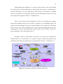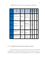
1
MAZEN MUNEER ABDULKAREM RASHED ii iii AUTOMATIC LIGHTING CONTROL SYSTEM BASED ON OCCUPANCY FOR WIRELESS SENSOR NETWORK MAZEN MUNEER ABDULKAREM RASHED Submitted to the Faculty of Electrical Engineering In partial fulfillment of the requirements for the award of the degree of Bachelor of Engineering (Electrical and Telecommunication) Faculty of Electrical Engineering Universiti Teknologi Malaysia JUNE 2012 iv v To my beloved father, and mother for their encouragement, support and blessing all time as well as to my lovely fiancé for her continuous assistance vi ACKNOWLEDGEMENT “In the Name of ALLAH, the Most Gracious and the Most Merciful” I wish to express my deepest and sincerest gratitude to all those who supported me all throughout the way of finalizing this project. I would like to express my sincere appreciation to my supervisor Dr. Nurul Mu’azzah, whose inspiring suggestions, support, guidance and daily encouragement helped me at every step of this project. I am deeply thankful to my academic advisors, Dr. Abu Sahmah, Dr.Usman and Eng.Sameer Al-Jilani, who have greatly aided me in shaping my ideas and continuously contributed towards improving my level of understanding. At the same time, I cannot forget my lovely colleagues to whom I share my sincere appreciation for supporting me by all means and at all times. Last but not least, my special thanks to my father, mother, and to my whole family for their love, encouragement and support which without it I would not have been able to complete this work. My sincere appreciation also extends to my fiancé and friends for their advice and motivation. vii ABSTRACT Wireless sensor networks (WSNs) perform a significant task in facilitating every individual’s daily life. The contribution of WSNs to smart and initiative environment places them at the highest level of developers’ priorities. They basically consist of numerous small sensor nodes that subsequently cover wider ranges. These nodes are linked to each other and communicate with a coordinator unit via wireless medium. Nowadays, a greater proportion of the monitoring technologies are based on WSNs. Their widespread applications are in the field of traffic control, measurements and occupancy detection. WSN future is promising with many applications, especially in automation devices and smart services. This project focuses on one of the current applications of WSNs which is occupancy detection. Famous well-marketed examples that implement this technology in occupancy detection include security alarms, CCTV monitors and object trackers. The occupancy detection phenomenon of a type of sensors called Passive Infrared Radiation sensors (PIR) is exploited. The implemented system takes the advantage of PIR sensor mechanism to develop an automatic lighting control system that switches the lights on/off depending on the obtained occupancy results. The project has vital uses in public places to aid reducing power consumption and thus greatly decreasing the current expenditure on daily-consumed power by a great percentage reaches to 90% based on the location and the surrounding environment. The system is mainly built of two sensor nodes and an end node. The sensor node consists of a PIR sensor as well as a controller IC on a complete circuitry connected to a transmitter. On the end node, a receiver module of 315 MHz connected to the main light switch operating as an automatic light control switch. The circuits’ schematic design is accomplished using Proteus Professional 7.8 SP2. The motion detection circuit, transmitter and receiver wireless modules are using (PIC16F876A) microcontrollers programmed using MPLAB IDE v8.30. ABSTRAK Rangkaian pengesan wayarles (WSNs) memainkan peranan yang penting dalam membantu kehidupan seharian setiap individu. Sumbangan WSNs kepada persekitaran yang pintar dan inisiatif meletakkan mereka di tahap yang tertinggi dalam senarai keutamaan pemaju. Pada asasnya, WSNs terdiri daripada beberapa nod pengesan yang kecil yang kemudiannya dapat meliputi rangkaian yang lebih luas. Nod-nod ini dikaitkan antara satu sama lain dan berkomunikasi dengan unit penyelaras melalui medium tanpa wayar. Pada masa kini, kadar teknologi pemantauan yang lebih besar adalah berdasarkan pada WSNs. Aplikasinya digunakan secara meluas dalam bidang kawalan lalu lintas, pengukuran dan pengesanan activiti manusia. WSN menjanjikan masa depan yang cerah dengan lebih banyak aplikasi, terutamanya dalam peralatan automasi dan perkhidmatan pintar. Projek ini memfokus kepada salah satu aplikasi semasa WSNs iaitu pengesanan kehadiran manusia atau aktiviti manusia. Antara pengesan aktiviti manusia yang terkenal dan menggunakan teknologi ini adalah penggera keselamatan, pemantauan CCTV dan pengesanan objek. Fenomena pengesanan ini atau lebih dikenali sebagai pengesan Sinaran Inframerah pasif (PIR) telah dieksploitasikan. Sistem yang dilaksanakan menggunakan kelebihan daripada mekanisme pengesan PIR untuk membangunkan sistem kawalan pencahayaan automatik yang mengawal lampu sama ada bernyala atau padam dimana ianya bergantung kepada kewujudan manusia. Kegunaan projek ini sangat penting di tempat-tempat awam kerana ianya dapat membantu mengurangkan penggunaan kuasa dan seterusnya dapat mengurangkan perbelanjaan semasa ke atas kuasa harian yang digunakan dalam peratusan besar sehingga mencecah 90% berdasarkan lokasi dan persekitaran. Sistem ini dibina daripada dua pengesan nod dan nod akhir. Pengesan nod terdiri daripada pengesan PIR yang berfungsi sebagai pengawal IC pada litar yang lengkap yang bersambung dengan penghantar. Pada nod akhir, modul penerima (315MHz) disambungkan kepada suis lampu operasi yang utama dan berfungsi sebagai suis lampu kawalan automatik. Dengan menggunakan Proteus Professional v7.8, reka bentuk skematik litar berjaya dihasilkan. Modul pemancar dan penerima tanpa wayar menggunakan pengawal mikro (PIC16F876A) diprogramkan dengan menggunakan MPLAB IDE v8.30. TABLE OF CONTENTS ACKNOWLEDGEMENT ........................................................................................................ vi ABSTRACT .............................................................................................................................. vii ABSTRAK ................................................................................................................................... i TABLE OF CONTENTS ........................................................................................................... i LIST OF TABLES .................................................................................................................... iii LIST OF FIGURES .................................................................................................................. iv LIST OF APPENDICES .......................................................................................................... vi LIST OF ABBREVIATIONS ................................................................................................. vii CHAPTER 1 ................................................................................................................................1 INTRODUCTION ..................................................................................................................... 1 1.1 Project Background ............................................................................................... 1 1.2 Problem Statement ................................................................................................ 3 1.3 Objective ............................................................................................................... 3 1.4 Scope of the Project............................................................................................... 4 1.5 Report Outline ....................................................................................................... 6 CHAPTER 2 ................................................................................................................................7 LITERATURE REVIEW .......................................................................................................... 7 2.1 Introduction ........................................................................................................... 7 2.2 Background of Wireless Sensor Network ............................................................. 8 2.3 Brief Descriptions on the project levels .............................................................. 11 2.4 Wireless Communication Network (WSN)......................................................... 12 2.4.1 Choosing the most suitable standard to adopt for the project .................. 14 2.5 Occupancy Sensor ............................................................................................... 15 2.6 Related Work....................................................................................................... 18 ii 2.6.1 Energy Saving by Automatic Control of Power in Simple Home Appliances ........................................................................................................... 18 2.6.2 An Intelligent Home Networking System ............................................... 19 CHAPTER 3 ..............................................................................................................................20 METHODOLOGY .................................................................................................................. 20 3.1 Literature Review and Data Collection ............................................................... 20 3.2 Project Virtualization .......................................................................................... 21 3.3 System Schematic Design ................................................................................... 21 3.4 Hardware and Software Development ................................................................ 22 3.4.1 Main System Components ....................................................................... 23 3.4.2 Software Development ............................................................................ 32 3.5 Design Testing..................................................................................................... 37 CHAPTER 4 ..............................................................................................................................39 RESULTS AND DISCUSSION ............................................................................................. 39 4.1 Overall Results .................................................................................................... 39 4.2 Technical Results ................................................................................................ 42 4.2.1 Results from Motion Detection Sensor Node .......................................... 42 4.2.2 Results from End Node............................................................................ 44 4.2.3 Results from Wireless Units .................................................................... 45 4.3 Complete System Functions ................................................................................ 45 4.4 Case Study ........................................................................................................... 47 4.5 Cost of the Project ............................................................................................... 48 4.6 Discussion ........................................................................................................... 50 CHAPTER 5 ..............................................................................................................................52 5.1 Conclusion ........................................................................................................... 52 5.2 Recommendations and Future Work ................................................................... 53 REFERENCES ..........................................................................................................................54 APPENDICES ................................................................................................................... 56 - 61 iii LIST OF TABLES TABLE NO TITLE PAGE Table 2.1 Examples on sensor types and their outputs [8, 9]. ..................................................... 8 Table 2.2 The most common wireless standards based on EPRI Report. ................................. 14 Table 2.3 Conducted study on the power savings potential [1] ................................................ 17 Table 2.4 The average power saving for different locations [1] ............................................... 17 Table 3.1 KC778B pins connection specifications [18]........................................................... 29 Table 3.2 315 MHz RF Transmitter Specifications [20] .......................................................... 30 Table 3.3 315 MHz RF Receiver Specifications [20] .............................................................. 31 Table 4. 1 Comparison on project implementation cost............................................................ 49 Table 4. 2 Comparison between the implemented systems and the available in market .......... 51 iv LIST OF FIGURES FIGURE NO TITLE PAGE Figure 1.1 Project complete design units. ................................................................................. 5 Figure 2.1 Wireless sensor network (WSN) for surveillance applications. .............................. 9 Figure 2.2 Equation towards understanding WSN.................................................................... 9 Figure 2.3 Integration of WSN in different fields of life ........................................................ 10 Figure 2.4 Common applications of wireless sensor networks [9] ......................................... 11 Figure 2.5 Illustration of automatic light control .................................................................... 16 Figure 3.1 Motion detection circuit with KC778B IC on breadboard .................................... 22 Figure 3.2 Motion detection circuit with microcontroller on breadboard............................... 23 Figure 3.3 Motion detection circuit with KC778B IC on donut board ................................... 23 Figure 3.4 PIR sensor .............................................................................................................. 24 Figure 3.5 PIR sensor dimensions [17] ................................................................................... 24 Figure 3.6 PIR motion detection range. .................................................................................. 24 Figure 3.7 KC778B IC Model................................................................................................. 26 Figure 3.8 KC778B Pins assignation [18] .............................................................................. 26 Figure 3.9 315 MHz RF transmitter [19] ................................................................................ 30 Figure 3.10 315 MHz RF Receiver [21] ................................................................................... 31 Figure 3.11 Communication process [20] ................................................................................. 32 Figure 3.12 Motion detection microcontroller programming with MPLAB IDE v8.30........... 33 Figure 3.13 Motion detection circuit with PIC16F876A flow chart ......................................... 34 Figure 3.14 315 MHz transmitter module flow chart ............................................................... 35 Figure 3.15 315 MHz receiver module flow chart .................................................................... 36 Figure 3.16 The stages of project development ........................................................................ 38 Figure 4.1 Most common places to implement WSN automatic light control. ...................... 40 Figure 4.2 Installation of the system ....................................................................................... 41 v Figure 4.3 Possible installation packages of sensor nodes...................................................... 41 Figure 4.4 Automatic light control complete system .............................................................. 42 Figure 4.5 Sensor node with KC778B IC ............................................................................... 43 Figure 4.6 Sensor node with PIC16F876A ............................................................................. 43 Figure 4.7 End node (315 MHz Receiver + automatic light switching) ................................. 44 Figure 4.8 Automatic light switching subsystems .................................................................. 46 Figure 4.9 Complete system scenario ..................................................................................... 46 Figure 4.10 Switching lights on/off based on occupancy detection ......................................... 47 Figure 4.11 Comparison on the number of hours lights are kept on with the use of automatic control system ..................................................................................................... 48 Figure 4.12 Current available light control devices ................................................................. 49 vi LIST OF APPENDICES APPENDIX A. Motion Detection with KC778B IC and PIR Sensor Schematics ........ 56 APPENDIX B. Motion Detection with PIC16F876A and PIR Sensor Schematics ....... 57 APPENDIX C. 315 MHz Transmitter Module Schematics ........................................... 58 APPENDIX D. 315 MHz Receiver Module Schematics ................................................ 59 APPENDIX E. Motion Detection Circuit with PIC16F876A, PCP Layout ................... 60 APPENDIX F. Motion Detection Circuit with KC778B IC, PCP Layout ..................... 61 vii LIST OF ABBREVIATIONS AC - Alternative Current dB - Decibel unit DC - Direct Current EPRI - Electric Power Research Institute. IC - Integrated Circuit. I/O - Input/ Output LDR Light dependent resistor OECD - Organization for Economic Co-operation and Development PCP - Printed Circuit Board. PIC - Peripheral Interface Control PIR - Passive Infrared Radiation RF - Radio Frequency RFI - Radio Frequency Interference UART - Universal Asynchronous Receiver Transmitter WSN - Wireless Sensor Network CHAPTER 1 INTRODUCTION 1.1 Project Background In the last few years, WSNs have been positively affected by the rapid revolution in the field of technology. Several researches were conducted to help in the development of WSNs for its wide range of applications. The greatest advantage of WSNs that is in terms of information gathering methods has made this technology one of the developer’s highest priorities. This is related to the sophisticated structure of WSNs, which mainly consists of several selforganized sensing nodes that operate together to collect data information. In each node, a sensing device is attached to it in order to monitor and gather data. The data is then processed and transmitted with the aid of wireless network to the coordinator node; where action is taken depending on the received signal and users predefined criteria. Some of the widely used applications of WSNs operate in the detection of motion, temperature, heat, optical light, radiation, chemical reactions, current and voltage variation, bandwidth acceding, position and acceleration. It is expected to have further more applications added daily to the list of WSNs. This project investigated the application of WSN in the field of motion detection. There are two types of motion detection sensors, which are categorized depending on 2 how they detect motion. The first type is known as active sensor, while the second one as passive sensor. An active sensor operates on emitting energy, mostly in the form of ultrasonic sound waves, directed into the desired area. This type of sensors is also called radar based motion detector. A passive sensor is characterized as the type of sensors that does not emit any form of energy. However, it is able to detect any changes in the energy level, based on predefined criteria. The motion detection based on passive sensors has its endless list of practical system applications in smart environment, such as security alarming, object tracking and camera monitoring. Another new application, which is the core of this project, is that automatic lighting control system based on WSN. The importance of this type of system stands behind the daily increase of the electricity power consumption cost. It is known that lighting system consumes a considerable amount of electricity power in our houses, universities, schools, hospitals, industries and in public places. The challenge is to reach a solution that help to reduce the power consumption. The project was based on human motion detection that operates on controlling the lighting system of a place when an individual passes through or comes across an area under the range of the motion detection sensor network. The sensor that was used in this project is called Passive Infrared Radiation sensor (PIR). This type of sensors is very sensitive to any changes in the infrared field surrounding it, and produces a signal whenever a disturbance occurs. The disturbance is in the form of heat emitted from a human body as he/she passes through the range of detection. This disturbs the infrared field around the motion detection sensor indicating a positive motion. Then action is taken either to switch on or off the lights based on whether a motion is detected or not in that area. 3 1.2 Problem Statement Nowadays the world is facing a terrifying increase of electrical power consumption cost which makes it significantly important to reduce the amount of consumed power. Several statistical researches revealed that the lighting system consumes almost the highest percentage of electricity power, particularly in public places, industries, educational institutes as well as in our houses. The percentage of the consumed electricity reaches almost to 80% of the total consumed energy as in the case of public places [1]. These results highlight the importance of taking serious actions to bring to an end the high percentage of wasted energy when nobody is taking its advantage. This in turn will help also in reducing the amount of money paid for such unused energy. Furthermore, the rapid technology development increased the need for intelligent automation devices and services, which became crucial to live in a smart environment . The challenge now is to develop a stable WSN that can detect the presence of human body. The system should not be affected by the change of room temperature and day-time. Moreover, the system must consume the lowest energy for its operation to save the highest possible amount of electricity power and to reduce the amount of electricity bills to be paid [2]. 1.3 Objective The main objective of this project was to develop human motion detection circuit that is able to detect the heat emitted from human body and then to transmit a signal to the coordinator unit at the end node. At the end node, the automatic light switching occurs based on the occupancy of the place. 4 The circuit was designed to operate automatically on controlling the lighting system of an area covered by the detection range of the motion detection circuit. It depends on the detection result obtained from the sensor nodes with the aid of wireless communication network. 1.4 Scope of the Project The scope of this project was to develop a motion detection circuit designed to satisfy the requirements for lighting control system. It was achieved with the aid of softwares such as Proteus and Altium. Some factors were taken into consideration such as, daytime temperature changes and the environmental factors that might degrade the performance of the design. The most appropriate results were obtained by choosing the right values of sensitivity and timing parameters, which are suitable to the requirements of the system to achieve the highest performance efficiency, and to reduce the high cost. At the same time, the project focused on making use of the available components to build a sophisticated lighting control system, with the lowest possible cost compared with the existing types in the market. Another principal scope of this project was to integrate the concepts and protocols of WSN into hardware design and choose the appropriate available wireless communication standards to be implemented in the design. In this project, two of 315 MHz wireless transmitters and a receiver were used to build the wireless network because of the distance range of transmission and reception of these two modules is quite sufficient for such a system. Moreover, the required operating power is very small compared with the other wireless standards, where a battery of 9 volt is sufficient to feed the system for a longer time of operation. The design requires using microcontroller programming language, where Micro C is used with the aid of MPLAB IDE v8.30. 5 The following block diagram explains the complete designed units, where all the components are joined to form the complete project design Figure 1.1 Project complete design units. 6 1.5 Report Outline This report is organized into six chapters. Chapter 1 gives an overview of the project with an introduction. Chapter 2 covers literature review on wireless sensor networks and motion detection as well as on related previous work. Chapter 3 describes the methodology including hardware and software development of the project. Chapter 4 describes the results and discussion of the complete project implementation. Chapter 5 presents the conclusion of this project and recommendations for future work and improvements. CHAPTER 2 LITERATURE REVIEW 2.1 Introduction Several studies were conducted in the area of motion detection for different kinds of applications. A great number of projects were built to reduce the power consumption. However, most of the projects did not use PIR sensors as the detection sensor and none of them applied the wireless medium for delivery [3]. This project was a continuation of previous projects designed by Mohd ‘Izzul Hafizuddin [4], Mohd Zharif Bin Anuar[5], Nurul Syuhada [6] and Law Che Hang Anthony [7]. It utilized the concepts and ideas that have been implemented in the abovementioned projects, to facilitate the building up of a new system. The expected design made use of the PIR sensors to detect human motion. The approach comprised the interference caused in the infrared field by the heat emitted from the human body. The detected results are forwarded to the transmitting unit, where the signal is transmitted in 315 MHz to the receiving unit at the end node. At this point, the coordinator unit compares the received result at the receiver model to the user’s predefined criteria. Then the light switching circuitry, which is connected to the output of the coordinator unit either switches on or off depending on the decision taken. 8 The basic form of motion detection via WSN consists of two main types of nodes, which are sensor node and end node. In this project, the sensor node consists of motion detector and transmitter, while the end node consists of receiver and light switching circuitry. 2.2 Background of Wireless Sensor Network Sensors are defined as hardware devices that produce a measurable response to a change in physical condition like temperature, pressure, humidity, light, etc. Sensors work on monitoring the physical change in a given scenario to produce results based on defined criteria whenever a change occurs. Table 2.1 Examples on sensor types and their outputs [8, 9]. 9 A sensor node is normally small and consumes very low energy for its operation. Wireless sensor nodes mostly consist of very small electronic devices equipped with limited power source. A battery of 9 volts or less is normally enough to feed such a system and some of the most commonly used sensor nodes for different applications: MiCA2 – 700 MHz, TelosB – 2.4 GHz, MICAz – 2.4GHz, Imote2 - 2.4 GHz and XBee – 2.4 GHz [7]. WSN was firstly introduced in military applications. This was due to several factors, such as its small size, power consumption and other aspects that make it so beneficial in the battlefield surveillance as illustrated in Figure 2.1. Due to the diverse variety of WSN applications, dramatic development in WSN field technology is taking place globally. At the current time, WSN has become popular and is mobilized in several civilian areas and industrial applications. Figure 2.1 Wireless sensor network (WSN) for surveillance applications. The concept of wireless sensor networks is simply understood by the following equation: Sensing + processing + Radio = Thousands of potential applications. That is illustrated in Figure 2.2. Figure 2.2 Equation towards understanding WSN 10 Understanding the capabilities of a wireless sensor network is the reason behind the widespread of its famous applications, which include the concept as a combination of modern technologies. In some applications WSN consists of thousands of installed sensors in a specified area and operate together without suffering interference from each other while delivering their results to a coordinator unit. Once a sensor detects physical changes as in the case of temperature, pressure and speed, depending on the type of sensors; it generates a corresponding signal. The signal is then sent through the wireless network medium until it reaches the coordinator unit to be processed. The coordinator unit is where decision-making takes place after comparing the received data information with the input criteria. Finally, an action is taken depending on the related application [7]. Nowadays, WSN is found almost everywhere in our life and is integrated in different fields as in biomedical uses, military weapons, habitat monitoring, home automation and commercial applications as demonstrated in Figure 2.3 and Figure 2.4. Figure 2.3 Integration of WSN in different fields of life 11 Figure 2.4 Common applications of wireless sensor networks [9] The application of WSNs in lighting control system provides a practical idea towards the direct use of artificial intelligence techniques. This application needs decision making when a doubtful situation is faced. It places such a system of great demand in the market due its importance and fundamental benefits. 2.3 Brief Descriptions on the project levels There were four main levels in the project that were important for the construction of a complete system of automatic lighting control based on occupancy for WSN. They were as follows: I. PIR Sensing Circuit: The detection unit of the system is responsible to sense for motion, indicating human presence or absence in a specific area. It generates information signal of the sensed data to be processed by the coordinator for further action. 12 II. Wireless Communication Network: The connection is between the sensing circuit and the coordinator unit. It consists of transmitter and receiver. The transmitter is used to send the sensed data in the PIR sensing circuit and transmit it through the wireless medium in frequency of 315MHz. On the other hand, the receiver is used to pass the received signal to the coordinator unit for further processing. III. Coordinator: The headquarter unit in the system which is responsible to manage the data transmission from the sensor nodes and processes the received sensing. IV. Lighting control unit: The circuit operates as a switch to on or off the lights in a specific area based on the command received from the coordinator unit. 2.4 Wireless Communication Network (WSN) Currently, several wireless standards are available in the market with brilliant features and reasonable price, such as Wi-Fi, Bluetooth and GPRS, which are the most commonly used in current designs. When choosing wireless standard for a specific design, several criteria must be taken into account depending on the requirements of the system. The essential important criteria are transmission range, energy consumption, size, security and scalability. These criteria can be explained individually as: I. Transmission range: It is important to choose the best standard that fits the required range of transmission of the system. Some designs need smaller range for the signal to reach the coordinator unit, so using a standard with higher range is a waste of bandwidth and may cause interference with other signals. On the 13 other hand, some designs require higher range of transmission, when the coordinator unit is at great distance from the transmitter. II. Energy consumption: It is very important to take into account the required power to operate the expected design. In the case of sensors, normally a battery and most of the time a non-rechargeable one is used, as in this project. The chosen standard has to minimize the needed power of operation of the whole system, so that the battery can last for a longer period. III. Size: Sensor nodes are mostly small and hence they can be easily installed in the needed areas. Since the power supply is very limited, we try to avoid complexity that may cost higher power consumption. IV. Security and reliability: Based on the specifications of the design, it is required to decide whether secure and reliable signal transmission is needed between the source node and end node or these two criteria may not have a great importance. However, sometimes it is important to have reliable transmission of the signal between the two nodes, while security may not be an issue V. Scalability: It is known that in some situations, WSN is built of numerous sensor nodes approximately more than thousands that operate together and transmit their monitored results at the same time without being affected by interference or exceeding bandwidth. Choosing the right standard for the design will contribute to better performance [7]. In Table 2.2 a comparison has been made between most of the common used wireless standards in the market to highlight their strengths and weakness as well as to show their suitable applications. 14 Battery life (days) Transmission Range (meters) Bandwidth (kb/s) System resources Weaknesses Strengths Applications IEEE standard Table 2.2 The most common wireless standards based on EPRI Report. Additional security layers required. 11,000+ Easy deployment falling costs. Limited within customers’ site. 1-100 Access between WAN networks and customers’ site. 1-5 Wi-Fi (IEEE 802.11) 1Mb + Connection with customer’ site. Accessing web, emails and videos. 2.4.1 20-250 1-100+ 100 -1000+ 720 Higher operation power required 64- 128+ Higher cost of equipment and implementation 1-10+ Transmission of voice and data for longer distance Security vulnerabilities& short range 1000+ GPRS/GSM Higher transmission range and lower bandwidth Limited maximum number of devices in a network 1-7 Cable replacement More mature than ZigBee& higher data rates than ZigBee More secure than other standards 1-7 Connection of sensors and other equipment in a customer LAN. Designed for industrial use and home automation or security applications. Limited range& lower data rates (probably sufficient) 250Kb+ Bluetooth (IEEE 802.15.1) Connection of sensors and other equipment in a customer LAN. Good scalability 16Mb+ ZigBee (IEEE 802.15.4) Reading user interface at customers’ site. 4Kb-32Kb Low power and implementation cost. Choosing the most suitable standard to adopt for the project Table 2.2 indicates the power consumption for the operation of Wi-Fi, Bluetooth and GPRS/GSM is very high and the battery cannot last for more than seven days. It is expensive and not practical if we keep changing the battery every week. In addition, the 15 transmission range in Bluetooth is very short, while it is more than needed in GPRS/GSM, for sensor nodes. Moreover, the high cost of GPRS/GSM equipment and Bluetooth causes limitation on the maximum number of devices that can be added to a network, thus excluding them from being used in such project. Indeed, ZigBee standard was the best fitting model for this project due to its sufficient range, low power consumption, scalability, and reasonable hardware cost. However, this project implemented a system with a simplified version of ZigBee, which has lower cost, smaller size, higher power conservation and can easily be built to suit the requirement of the design [10, 11]. 2.5 Occupancy Sensor Occupancy sensor is simply a device that is able to detect the presence or absence of human body in the sensor's range and is able to respond with a suitable signal. The system is usually built of a sensor, control unit IC or PIC and control switch circuit. Wireless communication network is the connection medium between the control unit and the control switch circuit. Occupancy sensors are mostly used in applications that require a higher intelligence control that cannot be achieved using scheduling. Such a system is powerful to use in places such as restrooms, offices, storage areas, classrooms, conference rooms, corridors, break rooms, and other places where lights are normally left on, even if the place is not occupied. Nevertheless, scheduling mostly fits implementation in entire buildings that can be controlled on a fixed schedule. Occupancy sensors are able to reduce the power consumption by 50 percent or more in some situations depending on the specific characteristic surrounding and design of the place [12]. 16 The two well-known types of occupancy sensors are the passive infrared (PIR) and ultrasonic detectors as mentioned in the project background. Each of the two techniques has their own advantages and disadvantages as well as their special range of applications. PIR sensors detect the changes of heat emitted by humans when they are in motion from that in the surrounding environment. This type of sensors requires a line of sight to sense motion; while it is unable to detect movement behind obstacles. Ultrasonic sensors integrate the Doppler concept in order to detect occupancy by emitting very high ultrasonic frequency signal into space, and sense the reflected signal frequency, and then interpret the change in frequency as a motion in that area. This type of sensor has the advantages that it does not require a line of sight to detect motion around corners, unless a fabric partition walls exists. They are suitable for open places and also spaces with obstacles [13]. In this project, PIR sensor was implemented as it possesses the characteristic of being capable to function safely in closed places when located at suitable position. In addition, PIR sensor covers a wider range of motion detection when no obstacles block the detection line of sight. It is the best choice to provide a convenient environment by turning on the lights automatically when a person enters a room. PIR sensor is able to reduce the lighting energy consumed by turning off the lights after a short time when the last occupant leaves the room. Figure 2.5 Illustration of automatic light control 17 Researchers conducted a study on the power savings potential with occupancy sensors (before the implementation in wireless networks), in buildings spread in 24 states. The study monitored the occupancy and the number of hours the lights kept on in 158 rooms, 35 classrooms, 37 private offices, 33 conference rooms, 11 break rooms and 42 restrooms. They were able to reach the listed results in Table 2.3 of the potential energy saved [1]. Table 2.3 Conducted study on the power savings potential [1] It is possible to reach an average of 80% power saving based on the characteristics of the place required to be controlled as shown in Table 2.4. This actually applies for places which are normally unoccupied, or occupied for a short time. The process is clear as to how the occupancy sensor can contribute to conservation of power consumption as well as to provide a more convenient environment with intelligent automation devices. Table 2.4 The average power saving for different locations [1] 18 2.6 Related Work In this section, some previous related works concerning energy saving based on occupancy detection are discussed. Most of these related projects focus more on providing a smart environment to the user as well as to help in the reduction of wasted energy. 2.6.1 Energy Saving by Automatic Control of Power in Simple Home Appliances The world today focuses more on energy saving devices for efficient power management, which require specific controlling mechanisms and managed most of the time by a microcontroller. The mechanisms can be of light control based on natural light intensity in a specific place, fan speed control based on the room temperature and motion detection based on the presence or absence of occupants in that place [14]. Light dependent resistance (LDR) can be utilized in order to read the level of natural light intensity whether it is below the preset threshold predefined value, so lights will be turned on or vice versa. Room temperature can be taken from temperature sensor like LM35 to be compared with the predefined value. If the collected readings are higher or equal to the predefined threshold then the fans will run at their high speed. On the other hand, if it is some degrees below the predefined threshold, the fans will be turned off. The fan speed is represented by the voltage, where the speed can be changed by varying the voltage level supplied to the fan. Motion detection is achieved with the aid of a PIR sensor. When the room is unoccupied for a predefined duration, the loads presented by the fans are turned off to reduce the power consumption [14]. 19 2.6.2 An Intelligent Home Networking System Another focus of the world’s developers nowadays is concerning home networking systems, which mainly operate on energy monitoring and controlling. That is due to the increase of awareness related to the need of decreasing energy consumption especially for of home appliances. The system mainly consists of light dimmer switches that are wirelessly controlled, smart outlets, remote controllers and PIR sensors. The system can be utilized with ZigBee 2.4GHz wireless communication protocol for lower cost, longer transmission and higher reliability. Light dimmer switches are managed wirelessly by a remote control with special sensors like LDR instead of the typical mechanical buttons for more convenient and smart house experience. Power consumption is controlled with smart outlets by home energy controller based on the determined level of required power, which is then used to perform predefined user’s tasks [15]. The use of home energy controller as a platform inside households, will give the ability to users to write recipes which will be used to automatically control smart outlets by defining a list of tasks for each variation in the energy consumption plan. An example of such a genius system is the presence detection sensors, which can recognize unoccupied place where the recipe’s predefined operation would be to turn off the lights. In this way, users can control the energy consumed in their houses in an efficient and intelligent way. That is due to the fact that any predefined task will be triggered whenever the thresholds limitations are violated leading to automatic performing the necessary task. It has been proven that such home energy controller responds immediately with accurate action as designed and can be further developed to utilize various sensors data and process them for complete automatic control of smart outlets [15]. CHAPTER 3 METHODOLOGY This chapter will explain the methodology used in the development of wireless sensor network to achieve automatic light control system. The methodology in this project was divided into five stages, which are literature review, project virtualization, schematic design, hardware and software development and design testing for further development. 3.1 Literature Review and Data Collection In this stage, information on sensor nodes, occupancy sensors, PIR sensors, sensor applications and existing automatic light control systems, were gathered from different sources to build the project on a strong basis with profound knowledge foundation and deep knowledge. It had further helped to lessen and avoid the errors that were encountered in previous projects and helped gaining the benefits from previous relevant ideas and recommendations. In addition, a study has been undertaken on wireless sensor network standards and architecture to build the project on a suitable standard. Furthermore, some statistics have been collected regarding the estimated power consumption reduction percentage when the project is successfully implemented. 21 3.2 Project Virtualization In this stage the mapping of the whole project and planning for the steps needed to be taken were demonstrated for a successful design and implementation. The project was constructed with a pair of PIR sensor nodes allocated in separate distance from each other to cover a wider range. Hence, two motion detection circuits were fabricated and a transmitter was connected to each motion detection circuit to form the two sensor nodes. Single-pole relay was utilized to link the output of the motion detection circuit with the input of the transmitter. On the other hand, only one receiver module will be required to form the end node, since it will function as a coordinator unit to the whole system. The output of the coordinator unit is then linked to the light control circuit via a single-pole relay. 3.3 System Schematic Design This is the principal stage for the successful implementation of the project. All the required parameters for accurate sensing were carefully chosen and noise cancellation techniques were implemented. Another aspect was to minimize the consumed power by the circuit so as to enhance the long lasting property of the battery which was considered a great priority in this stage. Four schematics have been done, which are motion detection circuit with KC778B IC, motion detection circuit with microcontroller, transmitter and receiver. The motion detection circuit with KC778B IC schematics was developed based on the data sheet provided by the manufacturer, while motion detection circuit with microcontroller was developed from an available security system to suite the requirements of the design. On the other hand, transmitter and receiver schematic design were modified from current available RF system in the market. 22 Proteus Professional version 7.2-SP2 was used in the schematic design of the sensor nodes and end node. Proteus is PCB design software that is used for schematic capture and PCB layout to provide one of the most powerful schematic design and simulation tools. It has the ability to design and simulate electronic circuits and model programmable devices, such as microcontrollers, microprocessors and various types of ICs. 3.4 Hardware and Software Development In this stage, the occupancy sensor detection circuit, wireless communication network, coordinator unit and lighting control circuit were implemented and fabricated. The next step in this stage was to program the microcontrollers in the transmitter modules, motion detection circuit and the receiver module. At the beginning, the circuits were built on breadboard and donut board for performance and functionality examination as illustrated in Figures 3.1 to Figure 3.3. When the circuit passed all the required tests in terms of correct motion detection and signal transmission, then it has been soldered on PCP boards. Figure 3.1 Motion detection circuit with KC778B IC on breadboard 23 Figure 3.2 Motion detection circuit with microcontroller on breadboard Figure 3.3 Motion detection circuit with KC778B IC on donut board 3.4.1 Main System Components This section explains briefly about the four main components used to build the system for the motion detection unit and the communication units, which are Passive Infrared Radiation sensor, KC778B Master PIR Control Chip, 315 MHz RF transmitter and 315 MHz RF receiver. 3.4.1.1 Passive Infrared Radiation Sensor (PIR) PIR is an abbreviation for Passive Infra-Red sensor. It is a Pyroelectric sensor, which detects human motion up to 5 meters from its installation position. It can sense objects up to 120° within 1 meter range. The operation requires voltage ranges between 24 5 V to 20V for the PIR sensor module and 2V to 3V for the PIR sensor unit. The dimensions of this sensor are very small as illustrated in Figure 3.4 [16, 17]. Figure 3.4 PIR sensor Figure 3.5 PIR sensor dimensions [17] The PIR Sensor range might vary based on the surrounding environmental conditions. The sensor is designed to adapt slowly with the environmental changes, but once a sudden change occurs in the surrounding environment such as a human motion within the range of the sensor is detected, it will give a high response on its output. The output will remain high as far as the motion is still in progress. The output will switch to low after approximately 2 to 4 seconds after the stop of motion. Figure 3.6 PIR motion detection range. Fresnel lens is used to focus the infrared field disturbed by the human motion on crystalline elements in the PIR sensor that generates an electric charge when exposed to infrared radiation. The changes in amount of infrared on the elements alter the voltages generated. There is also an infrared-sensitive IC that can monitor any change in the 25 infrared field’s pattern of the environment with any disturbance of heat emitted by human body movement [17]. There are two possible primary adjustments that need to be considered when dealing with PIR sensors. 1. Time delay: Control the time required for the sensor to wait before turning off the load after the place is unoccupied. 10-minutes of delay might be more convenient to turn lights off after the last person leaves the place. 2. Sensitivity level: It allows selecting the best sensitivity level between high, moderate or low based on the application. In security systems, it will be significantly important to choose higher sensitivity level, but for automatic lighting system, it is desirable to have moderate sensitivity to avoid false motion. 3.4.1.2 KC778B Master PIR Control Chip This project utilizes an IC called KC778B as the main controller IC of the sensing unit. The IC is designed to be a Master PIR Control Chip (MPCC) with easier implementation in types of systems with functions based on motion detection aided by PIR sensors. This is related to the fact that it has a high level of sensitivity and reliability here are several advantages of this ICwhich can be summarized as follows: it minimizes the external components, reduces the cost of implementation, saves time in skipping microcontrollers programming part, noise cancellation and its high immunity to RFI. 26 Figure 3.7 KC778B IC Model The IC can be adjusted for the gain value to be either 62 dB or 68 dB based on the application. In addition, the sensitivity in terms of motion detection level can be also adjusted based on the requirements. Band-pass filter internally integrated as a switched capacitor reduces the number of external components as well as improves reliability. The IC can be much more useful in application function based on daytime, where a photo diode can be used with this MPCC. The Operating chip voltage is between 4 - 15V, the operating current is normally 300 μ A and it can support 50-60 Hz AC line frequency [18]. The pins assigned on this chip have been configured to suit the design requirements. The data sheet provided by the manufacturing company was the main reference when deciding the values of the capacitors and resistors and the required connections based on the given data and applications. Figure 3.8 KC778B Pins assignation [18] 1. Vcc Pin: This pin is designed for the regulated voltage to operate the chip, where a voltage regulator will be connected to produce 5 Volt DC. 27 2. Sensitivity Adjust: The pin will be used for sensitivity threshold adjustment of the motion comparators. In this case, it will be connected to a variable resistor of 200K Ohm. It is applied for the adjustment of the sensitivity to a moderate level, in order to avoid fake motion detection, while it can be connected to the ground to have the maximum sensitivity for other applications. 3. Offset Filter: This pin is connected to an external capacitor, which will hold the average value of the band-pass filter output. Motion will be detected once a difference between this average and the actual filter output is greater than the value of sensitivity adjusted in pin 2. 4. Anti-Alias: This pin operates as a low pass filter of the PIR input signal to block input signals equal or above the switching frequency of the band-pass filter in pin 3. 5. DC capacitor: This pin is connected to another external capacitor that holds average pyro source voltage. The result obtained is based on the findings between the DC CAP average and the actual pyro source voltage in pin 8, which is then amplified and coupled to the band-pass filter connected in pin 3. 6. Voltage Regulator: This pin is not used in this system as its function is to produce an output regulated voltage while in this project we are implementing an external voltage regulator that produces 5 V DC in this system. 7. Pyro (D): This pin is connected internally to a noise cancellation circuit that improves the reliability and performance of the system. It contains the pyro drain reference voltage. The pin is connected to the pyro drain and externally connected to a capacitor. The voltage stored in the capacitor can supply the sensitivity adjustment pin that is connected to the potentiometer. 8. Pyro (S): This pin holds the pyro source input received from the PIR input signal. 9. Gnd (A): This pin is a ground for the internal analog circuit in the chip. 10. Gnd (D) : This pin is a ground for the internal digital circuit in the chip. 28 11. Daylight Adjust: This pin will not be used in this system as it is more related for daylight detection based on photo diodes, so it will be unconnected. 12. Daylight Sense: This pin will not be used in this system as it is more related for daylight detection based on photo diodes; thus it is needed to be connected to Vcc to cancel its function. 13. Gain Select: This pin is used to select the benefits of the PIR circuitry either to be 62 dB or 68 dB depending on the connection. In this system it is leaved unconnected to provide 68 dB. It can also be connected to Vcc to produce the same gain, while it will produce 62 dB of gain if it is connected to the ground. 14. ON/AUTO/OFF: This pin is not connected in this system to allow the chip to operate in its preconfigured operating mode that suits the application of automatic light control. 15. Toggle: This pin is used to determine the operation of the chip and needs to be unconnected as it depends on the connection state of pin 14. 16. OUT: This pin has the output of the chip, which will be connected to the load through a relay in this case. 17. LED: This pin is connected to LED that will be used to indicate whether a motion is detected or not; hence it will light on when a motion is detected. 18. Off Timer Delay (C): This pin is the input to the OFF timer oscillator, which will determine the period of detection and forward the results. The OFF timer delay in seconds of the system will follow the equation of: OFF timer delay = 5678 x (40,000 + Resistance in Ohms) x (Capacitance in Farads). 19. Off Timer Output (R): This is the output pin of the OFF timer 20. Frequency Reference: This pin holds 160 Hz reference of the oscillator input. 29 Table 3.1 KC778B pins connection specifications [18] Pin Name Description 1 Vcc Supply Voltage (5 V) 2 Sensitivity Adjust PIR Motion Sensitivity Input 3 Offset Filter PIR Motion Offset Filter 4 Anti-Alias PIR Anti-Alias Filter 5 DC CAP PIR Gain Stabilization Filter 6 VReg Voltage Regulator Output 7 Pyro (D) Pyro Drain Reference 8 Pyro (S) Pyro Source Input Signal 9 Gnd (A) Analog Circuitry Ground 10 Gnd (D) Digital Circuitry Ground 11 Daylight Adjust Daylight Adjustment and CdS Input 12 Daylight Sense Silicon Photo Diode Input 13 Gain Select PIR Gain Select Tri-State Input 14 ON/AUTO/OFF Mode Select Tri-State Input 15 Toggle Mode Select Toggle Input 16 OUT Lights ON/OFF Output 17 LED PIR Motion Indicator Output 18 C OFF Timer Oscillator Input 19 R OFF Timer Oscillator Output 20 FRef Frequency Reference Oscillator 30 3.4.1.3 315 MHz RF Transmitter This is a very low cost and small size RF transmitter that can be used to transmit a signal up to 100 meters. This type of transmitters mostly fits short distance transmission which applies to this project, where approximately 50 meters is sufficient for the communication between the sensor node and the end node. The required battery supply can vary between 2.5 volt to 12 volt based on the design of the module and the required transmission range [19]. Figure 3.9 315 MHz RF transmitter [19] The specifications of the transmitter provided by the manufacturer in terms of the transfer rate, transmission power, needed antenna length and operating power can be summarized as in Table 3.2. Table 3.2 315 MHz RF Transmitter Specifications [20] No. Specifications RF Transmitter Module 1. Operating Voltage 3V to 12V 2. Operating Current Max ≤ 40mA (12V). Min ≤9mA (3V) 3. Oscillator SAW (Surface Acoustic Wave) oscillator 4. Frequency 315MHz 5. Frequency error ±150kHz (max) 6. Modulation ASK/ OOK 7. Transfer rate ≤10Kbps 8. Transmitter power 25mW (315MHz at 12V) 9. Antenna Length 24cm 31 3.4.1.4 315 MHz RF Receiver This kind of receiver can be considered as the twin of the 315 MHz transmitter. It is also small in size and a low cost receiver that can receive any signal transmitted by a 315MHz transmitter. It is designed to operate with very low power consumption between 3V to 12V and 4 mA. It has a very high sensitivity to capture weak signals [20, 21]. Figure 3.10 315 MHz RF Receiver [21] The specifications of the transmitter provided by the manufacturer in terms of the transfer rate, transmission power, needed antenna length and operating power can be summarized as in Table 3.3. Table 3.3 315 MHz RF Receiver Specifications [20] No. Specifications RF Reciever 1. Operating Voltage 5.0V ± 0.5V 2. Operating Current ≤5.5mA at 5.0V 3. Operating Principle Monolithic super heterodyne receiving 4. Modulation OOK/ASK 5. Frequency 315MHz 6. Bandwidth 2MHz 7. Sensitivity -100dBm 8. Rate <9.6Kbps (315MHz at -95dBm) 9. Data Output TTL 10. Antenna Length 24cm 32 The following diagram illustrates the basic communication process between the transmission unit and the receiving unit. The push bottom in the transmission unit will be connected to the output of the sensing unit using a relay. The 7-segment display on the end node will be connected to the light control circuit through a relay as demonstrated in Figure 3.11 for the whole communication process between the transmitter module and the receiver module. Figure 3.11 Communication process [20] 3.4.2 Software Development At this stage, the motion detection circuit with microcontroller has been programmed to function on detection of human motion with two PIR sensor modules to cover wider range. Micro C programming language has been used with MPLAB IDE v8.30 to program the microcontroller as illustrated in Figure 3.12. After successful programming of the motion detection circuit, the next task was to finish the code development for the transmitter and receiver units. 33 Figure 3.12 Motion detection microcontroller programming with MPLAB IDE v8.30 MPLAB is a programming software that is used to develop applications for Microchip microcontrollers as well as digital signal controllers. It is considered as an Integrated Development Environment (IDE), since it provides a single integrated “environment” to ease developing codes for embedded microcontrollers. It brings many changes to the PIC microcontroller developments. Figures 3.13 to Figure 3.16 are the programming flow charts of the main system components, which are motion detection circuit with PIC16F876A, 315MHz RF transmitter module and 315 MHz RF receiver module respectively. 34 Figure 3.13 Motion detection circuit with PIC16F876A flow chart 35 Figure 3.14 315 MHz transmitter module flow chart 36 Figure 3.15 315 MHz receiver module flow chart 37 3.5 Design Testing The complete circuit has been tested for functionality and stability. Alterations and development have been considered. After a complete check on the performance of the system and no error was detected, then the final step was to connect it to the electricity power system to form the light control switching. Finally, observations on the project implementation have been collected to ensure it is properly functioning to announce the project success. The observations were based on data collection for detection range, transmission range, sensitivity, stability and automatic light switching functionality. 38 Figure 3.13 illustrates the different stages of the whole project implementation starting from literature review and data collection and ending by testing. Literature Review Project Virtualization Schemetic Design PIR Sensor Detection Unit Hardware Development Transmitter Unit Receiver Unit Software Development •PIR Sensor unit, Transmitter and Receiver Micrcontroler Programming. Testing •Examining all units: •Sensing Unit. •Transmitting Unit •Receiving Unit Light Control Circuit •Build the Light Control circuit and connect with the the whole system. Figure 3.16 The stages of project development CHAPTER 4 RESULTS AND DISCUSSION 4.1 Overall Results The outcome of this project was a complete system that can automatically control the lighting system of a place by detecting the presence or absence of human body utilizing occupancy wireless sensor network. The system consisted of a pair of sensor nodes, limited to a single pair for illustration, operates together to sense motion in a specific area. The sensed data is forwarded to the transmitter unit of each sensor node. Wireless signal is transmitted in 315 MHz from the transmitting unit built in the sensor node to acknowledge the detection of either positive or negative motion. The received signal is then processed in the coordinator unit, which is the receiver module in the end node. Another circuit was connected to the output of the coordinator unit to execute an action based on the decision taken in the coordinator unit. The action is either to switch the lights on or off depending on the sensed data of either a motion is detected or not within the range of the sensor nodes. The system was designed to help in reducing the power consumption in private and public places and to provide a more convenient and green environment. The percentage of reduction is based on the percentage of how often the place is occupied. It is estimated to reach more than 80% of power consumption reduction in places which are normally unoccupied. The average power consumption in places, which are normally 40 occupied, might vary between 30 – 50% as it is explained in details in the case study section [1]. This project can be utilized in various places such as university halls, classrooms, meeting rooms, libraries, public places, study rooms, offices, car garages, and any place which facilitates its practical application. Figure 4.1 Most common places to implement WSN automatic light control. The system can be easily implemented in new buildings design as well as in old ones, where the lighting system will be controlled automatically with wireless switch to provide a friendly environment. The switch demonstrates the lighting control circuit that was attached to the coordinator unit in this project. 41 Figure 4.2 Installation of the system The sensor node can be installed on a wall, roof or kept on a position where it can be exposed to have the maximum motion detection coverage area. When the sensor nodes are used in outdoors, protections need to be considered in order to avoid the sensor from being affected by sunshine, rain or dust. Figure 4.3 Possible installation packages of sensor nodes With the practical application of such a system, it will create much fun and comfort to live in a smart and elegant environment with highly user friendly devices. At the same time, we can reduce the energy consumption and contribute to the continuous maintenance of a healthy green environment. 42 4.2 Technical Results The project was successfully implemented and modeled for exhibition purposes to switch on /off two light bulbs connected in parallel as an illustration for real life lighting systems of halls, rooms, offices or any type of lighting systems. The complete project is illustrated in figure 4.4. Figure 4.4 Automatic light control complete system 4.2.1 Results from Motion Detection Sensor Node Two designs of sensor nodes were implemented for the purpose of cost, stability and features comparison. The first design implemented a KC778B IC and a PIR sensor on PCP board along with 315 MHz transmitter module as shown in figure 4.5. The second design applied PIC16F876A microcontroller and two PIR sensor modules fabricated on PCP board connected to another 315 MHz transmitter module as shown in figure 4.6. 43 Figure 4.5 Sensor node with KC778B IC Figure 4.6 Sensor node with PIC16F876A The sensitivity of both designs can be controlled. The IC based design sensitivity was controlled from the 200 K ohm variable resistor on the board, where it is preferable to be kept moderate for lighting systems to avoid false indication. On the other hand, the microcontroller based design sensitivity was controlled from the PIR sensor module either to be high or moderate. The sensors on both can detect any human motion in 3-5 meters away from the sensor node. The detection range varies based on the environment and the motion position as indicated in the literature review section. From the observation on the functioning of both sensor nodes, it was found that the microcontroller based design was much more stable compared to the IC based 44 design. Some false human detection results have been observed when using the IC based sensor node. On the other hand, the microcontroller based design exhibited a very smooth and accurate indication when human motion is detected. That can be explained by the fact that, the PIR sensor module as well as the PIC16F876A implemented in the microcontroller based sensor node; were designed to have an effective noise cancellation and to be less affected by the electromagnetic field interference compared to that implemented in the controller IC of KC778B. Another key feature in the microcontroller based sensor node is that, many PIR sensor modules can be connected to the same sensor node to cover wider area with one circuit, while only one PIR sensor can be connected to the IC based sensor node design [17, 22]. 4.2.2 Results from End Node 315 MHz receiver module connected to light control switch circuit was implemented and linked directly to the main power supply as well as to the lights of a place (Figure 4.7). For illustration it was successfully functioning on switching two bulbs on/off based on the occupancy of the place. In real life the on time can be set to 10 -15 minutes before the system shut down the lights in case of no motion is detected. In this project, the time was set to 10 seconds to examine its performance, but it can be easily changed to any value from the program codes of the receiver module. Figure 4.7 End node (315 MHz Receiver + automatic light switching) 45 4.2.3 Results from Wireless Units The transmitting unit and the receiving unit designs were assembled based on the requirements of the project design and to establish wireless communication media between the sensor node and the end node. The range of transmission achieved was between 50 -100 meters, where it also depended on the surrounding environment and thickness of obstacles around the sensor node. Single-pole relays were used to interface between the transmitter input and the output of the sensing unit on the sensor node. Another single pole relay was used to interface between the coordinator unit and receiver on the end node, and the power supply to operate as a switch to turn lights on or off the lights based on whether the place is occupied or not. 4.3 Complete System Functions Figure 4.8 shows closely all the system components in details. The system was divided into four subsystems. Subsystem (A) represents the first sensor node responsible about human motion detection and it is using a microcontroller with two PIR sensor modules for wider area coverage. Subsystem (B) represents the second sensor node using KC778B IC with one PIR sensor. Subsystem (C) is the end node where it is connected directly to the power supply of 220V AC and to the lights system to operate on automatic controlling the lighting system of the place. Subsystem (D) is an extra added circuit for future development. It is a part of a sensor node where an LDR as an extra feature is added to operate on dimming the lights based on the natural light intensity. 46 (C) End Node with 315MHz (A) Sensor node with receiver and automatic PIC16F876A, 315 switching circuit MHz transmitter and two PIR sensors (D) Motion detection circuit with KC778B IC, PIR (B) Sensor node with sensor and LDR KC778B IC, 315 (Designed for Future work) MHz transmitter and PIR sensor Figure 4.8 Automatic light switching subsystems The system was able to sense for human motion in the range of detection and when an occupant was detected the lights remained on for a duration set by the user and switched off automatically when no motion was detected during the time set. This is illustrated in Figure 4.9 and 4.10. Figure 4.9 Complete system scenario 47 Figure 4.10 Switching lights on/off based on occupancy detection 4.4 Case Study For illustrating the benefits of the project a case study has been conducted on a class room in Faculty of Electrical Engineering, UTM. The class’s schedule on Thursday for semester two 2012 was observed to notice the differences in case the project was implemented in such a scenario. The lights were normally switched on by the technician or students at 8 am and kept on until the end of the day where they were switched off by the technician at around 5:30 pm. It is obvious from Figure 4.11 the number of hours lights were kept on without necessity, which gave an idea of how much power was wasted in such scenarios. 48 Comparison on the number of hours lights are kept On in PO5-104 2 1.5 1 Lights On (H) without Automatic Light control 0.5 Lights On (H) with Automatic Light control 0 8 -10 10 -12 12 - 2 am pm pm 2-4 pm 4-6 pm Figure 4.11 Comparison on the number of hours lights are kept on with the use of automatic control system The implementation of the project will not just save more than 4 hours of wasted power on lighting a university class room in a normal day, which is about 40-45% of the average wasted energy on a normal day, but it will also provide a convenient way for students and technicians to have the lights switched on only when needed. 4.5 Cost of the Project The hardware and implementation cost of the project was much less than that of similar devices available in the market, even though this project implemented WSN technology to make it easier for the installation of this system in new constructions as well as in old constructions and to provide more convenient and smart environment. 49 Table 4. 1 Comparison on project implementation cost Table 4.11 indicates the differences between the implementation of both sensor node designs, where the microcontroller based design coasted around US$10 higher than that of the IC based. However, the microcontroller based design decreased the number of required sensor nodes to cover a wider area, since several PIR sensor modules could be connected to the same sensor node. Figure 4.12 Current available light control devices Figure 4.12 illustrates some of similar devices that have the same function as the implemented one in this project. However, most of them are used to switch a single light 50 bulb attached to the device directly without the use of WSN. The price range is between US$ 200 -700. The big difference between the implemented design in this project with those available in the market in terms of cost, functions and technology, will place it at a high demand in case it is developed, packed and send to the market. 4.6 Discussion The objective of this project has been fulfilled. This was illustrated by the successful implementation of the software and hardware as expected. From the achieved results, it has been proven that the system is able to switch the lights on/off based on the occupancy results and so reduce power consumption. In addition, the wireless communication standard implemented between the sensor node and the end node was effectively sufficient as expected. Table 4.2 summarizes the comparison between the two implemented systems in this project and the available ones in the market from different perspectives. 51 Table 4. 2 Comparison between the implemented systems and the current available in market Available devices IC based sensor node Microcontroller based in the market. device sensor node device Price US$ 100 plus US$ 43 US$ 50 Stability Stable Moderate Very stable WSN Support Non YES YES with 50-100 m range with 50-100 m range Operating power 9-12 V Battery 9-12 V Battery or 9- 12 V DC adapter 9- 12 V DC adapter Sensitivity High adjustable Adjustable Yes Yes i.e. Security Alarms, i.e. Security Alarms, CCTV Monitors and CCTV Monitors and Type of Device Supporting extra features No 9-12 V Battery or Air Conditioner On/Off Air Conditioner On/Off Supporting New and Old constructions Only new Both Both 52 CHAPTER 5 5.1 Conclusion Wireless sensor network applications have turned out to be a significant aspect in our daily life. Its wide spread application and the services provided by this green technology makes it one of the most popular areas of research and development. The revolution in technology always eases people’s lives and provides them with intelligent systems having higher quality services. One of these modern, advanced and intelligent systems is automatic light controlling based on motion detection sensors. This smart system will not just make life easier, while enjoying living in innovative and convenient environment, but it will also help in reducing the amount of money paid on wasted power. The system as a whole can be considered as an application of artificial intelligence, since it integrates decision making based on obtained results and predefined criteria. The number of sensor nodes needed for a particular area will always depend on the structure and design of the place, while it should be installed in a suitable place to monitor a larger area. At the same time, the choice of a suitable wireless standard will increase the performance of the system as well as it will minimize the cost and the power required for its operation. The sensor node based microcontroller and PIR sensor module was proved to have higher stability and less affected by noise. At the same time it decreases the number of required sensor nodes to one sensor node with multiple sensor modules to cover wider area. For the case of a small office, store or a single room the IC based sensor node is sufficient and with lower cost of implementation. 53 The detection range as well as the transmission range always depends on the surrounding area and the environmental conditions. The higher the line of sight, the higher the detection and transmission range. 5.2 Recommendations and Future Work The system can be further developed to add extra features such as security alarms and CCTV. For the case of security alarms, it can be achieved by adding a buzzer to the end node and a switch can be used to change between automatic light control and security alarm modes. The same thing can be applied for the case of CCTV, where it can be connected to the end node and start recording only when a motion is detected. For other appliances such as air conditioner, modification on the components power rating in the end node to handle high power is required, since the current system was designed specifically to handle low power appliances. Another extra feature can be added is, light dimming based on the daytime. This feature is supported by KC778B IC, but it is necessary to make some modifications on the motion detection circuit design to make use of pin 11, 12 and 15 to toggle the light based on the light intensity of the place measured by an LDR. 54 REFERENCES [1] Energy Saving Sensors. (2010, -2012). Energy Saving Tips for Lighting and Information on PIR Sensors Available: http://www.energysavingsensors.com/General-Information1.htm [2] C. H. Tsai, Y. W. Bai, C. A. Chu, C. Y. Chung, and M. B. Lin, "PIR-sensorbased Lighting Device with Ultra-low Standby Power Consumption," IEEE Transactions on Consumer Electronics, vol. 57, pp. 1157-1164, Aug 2011. [3] V. Singhvi, A. Krause, C. Guestrin, J. H., J. Garrett, and H. S. Matthews, "Intelligent light control using sensor networks," presented at the Proceedings of the 3rd international conference on Embedded networked sensor systems, San Diego, California, USA, 2005. [4] M. H. B. M. Solehuddin, "Development Of Wireless Sensor Network For Motion Detection," Bachelor Degree Wireless Communication Department, Universiti Teknologi Malaysia, 2010. [5] M. Z. Bin-Anuar, "Location Tracking Using Wireless Sensor Network," Bachelor Degree, Wireless Communication Department, Universiti Teknologi Malaysia, 2010. [6] N. S. Binti-Syamsuddin, "Design of Wireless Sensor Network for Environmental Monitoring (WiSNEM)," Bachelor Degree Wireless Communication Department, Universiti Teknologi Malaysia, 2008. [7] L. C. Hang, "Wireless Sensor Network," Bachelor Degree, Wireless Communication Department, Chines University of Hong Kong, 2007. [8] J. S. Wilson, Sensor technology handbook. Amsterdam ; Boston: Elsevier, 2008. [9] Organisation for Economic Co-operation and Development. (2012, -2012). OECD: Better Policies for Better Lives. Available: http://www.oecd.org/home/0,2987,en_2649_201185_1_1_1_1_1,00.html [10] D. Crouse, M. Diaz, and D. Budimir. (2004, -2012). Wireless Home Security System Available: http://www.ee.uconn.edu/SeniorDesign/projects/ecesd48/ECEProjectStatement.p df 55 [11] C. H. Chueng, "Wireless Home Security System," Bachelor Degree Wireless Communication Department, Universiti Teknologi Malaysia, 2008. [12] M. Lee, Y. Uhm, Y. Kim, G. Kim, and S. Park, "Intelligent Power Management Device with Middleware based Living Pattern Learning for Power Reduction," IEEE Transactions on Consumer Electronics, vol. 55, pp. 2081-2089, Nov 2009. [13] B. Ying-Wen, L. Zong-Han, and X. Zi-Li, "Enhancement of the complement of an embedded surveillance system with PIR sensors and ultrasonic sensors," in Consumer Electronics (ISCE), 2010 IEEE 14th International Symposium on, 2010, pp. 1-6. [14] K. M. Kadir, M. S. Forhad, M. M. Fadlullah, N. Quader, M. M. R. Al-Arif, and M. A. Dhali, "Energy saving by automatic control of power in simple home appliances," in Communication Software and Networks (ICCSN), 2011 IEEE 3rd International Conference on, 2011, pp. 311-315. [15] V. Nuhijevic, S. Vukosavljev, B. Radin, N. Teslic, and M. Vucelja, "An intelligent home networking system," in Consumer Electronics - Berlin (ICCEBerlin), 2011 IEEE International Conference on, 2011, pp. 48-51. [16] Murata Manufacturing, "Pyroelectric Infrared Sensors User's Manual V 7.0," May 2011 Japan. [17] Cytron Technologies, "PIR Sensor Module User's Manual V1.1 " December 2007 Malaysia. [18] COMedia Manufacturing, "KC778B Master PIR Control Chip (MPCC) Specification V 1.0," December 1994 China. [19] Cytron Technologies, "RF Transmitter Module User's Manual V 1.2," November 2008 Malaysia. [20] Cytron Technologies, "Sending Data using RF Module User's Manual V 1.2," August 2008 Malaysia. [21] Cytron Technologies, "RF Receiver Module User's Manual V 1.2," November 2008 Malaysia. [22] Microchip Technology, "PIC16F876A Data Sheet V 1.0," January 2003 USA. 9-12 V J1 PIR SENSOR SENSOR1 2 1 100n C6 LED 100u VO D3 1 Vcc R1 47k C7 220p POT 200K RV1 Sensitivity Adjust VI 78L05 U1 C2 SW-SPDT SW1 + 3 D2 1k GND 2 R6 1N4004 100n C1 100n 10u 10u C5 + C4 C3 + JWD-171-17 RL1 J2 1 2 3 4 5 6 7 8 9 10 56k R3 KC778B Vcc FRef Sensitivity Adjust R Offset Filter C Anti-Alias LED DC CAP OUT Vreg Toggle Pyro (D) On/Off/Auto Pyro (S) Gain Select Gnd (A) Daylight Sense Gnd (D) Daylight Adjust IC1 3k9 R2 Motion Detection Circuit Output 1 2 20 19 18 17 16 15 14 13 12 11 Vcc 1k R5 LED 10k D1 C8 R4 100n 4n7 C9 RV2 1M POT On Time Adjustment Transmitter BC547 Q1 Motion Detection Circuit Based on KC778B IC and PIR Sensor APPENDICES APPENDIX A. Motion Detection with KC778B IC and PIR Sensor Schematics 1N4007 SW-SPDT UIC00A Programmer Sucket SWITCH Vcc D1 PGC PGD 2 1 MCLR 9-12 V J1 SW1 1 3 5 7 9 2 4 6 8 10 + Vcc 10u 30p C4 VO 100n C5 4k7 R3 FREQ=20MHz VI 78L05 C1 3 U2 2 GND CRYSTAL X1 1 19 20 8 1 2 3 4 5 6 7 9 10 DIODE-LED RB0/INT RB1 RB2 RB3/PGM RB4 RB5 RB6/PGC RB7/PGD 1N4148 D3 PIC16F876A RA0/AN0 RA1/AN1 RA2/AN2/VREF-/CVREF RA3/AN3/VREF+ RA4/T0CKI/C1OUT RA5/AN4/SS/C2OUT RC0/T1OSO/T1CKI MCLR/Vpp/THV RC1/T1OSI/CCP2 RC2/CCP1 RC3/SCK/SCL Vss1 RC4/SDI/SDA RC5/SDO Vss2 RC6/TX/CK Vdd RC7/RX/DT OSC1/CLKIN OSC2/CLKOUT U1 30p C3 220R 100n D2 R1 C2 Vcc 11 12 13 14 15 16 17 18 21 22 23 24 25 26 27 28 1k R6 10k R5 4k7 R2 2N2222 Q1 LED D4 Vcc 220R R4 RESET MCLR GND VCC GND VCC 5VDC RL1 PIR SENSOR 2 PIR SENSOR 1 1 2 Output J2 Motion Detection Circuit Based on PIC16F876A Micrcontroller and PIR Sensor Module 57 APPENDIX B. Motion Detection with PIC16F876A and PIR Sensor Schematics 2 1 1N4007 SW-SPDT SEND DECREASE UIC00A Programmer Sucket MCLR PGC PGD + Vcc Vcc Vcc 30p VO 100n C5 4k7 R4 4k7 R2 4k7 R3 FREQ=20MHz Vcc 10u VI 78L05 U2 C1 3 INCREASE D1 SW1 Motion Detection Circuit 9-12 V DC input J1 1 3 5 7 9 2 4 6 8 10 2 GND CRYSTAL X1 C4 1 19 20 8 1 2 3 4 5 6 7 9 10 RB0/INT RB1 RB2 RB3/PGM RB4 RB5 RB6/PGC RB7/PGD 1N4148 D3 PIC16F876A RA0/AN0 RA1/AN1 RA2/AN2/VREF-/CVREF RA3/AN3/VREF+ RA4/T0CKI/C1OUT RA5/AN4/SS/C2OUT RC0/T1OSO/T1CKI MCLR/Vpp/THV RC1/T1OSI/CCP2 RC2/CCP1 RC3/SCK/SCL Vss1 RC4/SDI/SDA RC5/SDO Vss2 RC6/TX/CK Vdd RC7/RX/DT OSC1/CLKIN OSC2/CLKOUT U1 30p C3 DIODE-LED 220R 100n D2 R1 C2 Vcc 11 12 13 14 15 16 17 18 21 22 23 24 25 26 27 28 4k7 10k R13 R12 220R 220R 220R 220R 220R 220R 220R GND VCC Vcc Gnd Dot g f e 7-SEGMENT d Antenna 315 MHz RF Transmitter Data a b c d e f g Data (RC6) R11 R10 R9 R8 R7 R6 R5 RESET MCLR 315 MHz RF Transmitter Module c b a 58 APPENDIX C. 315 MHz Transmitter Module Schematics 9-12 V Input 2 1 SW-SPDT - + 220 V AC g ( 7-Segment) 1N4007 J3 D1 SW1 + - Vcc 10u 1k 30p VO 100n C5 FREQ=20MHz VI 78L05 C1 R9 + 3 GND 2 J1 1 2 C945 Q1 CRYSTAL X1 C4 1 19 20 8 1 2 3 4 5 6 7 9 10 RB0/INT RB1 RB2 RB3/PGM RB4 RB5 RB6/PGC RB7/PGD PIC16F876A 5VDC RL1 RA0/AN0 RA1/AN1 RA2/AN2/VREF-/CVREF RA3/AN3/VREF+ RA4/T0CKI/C1OUT RA5/AN4/SS/C2OUT RC0/T1OSO/T1CKI MCLR/Vpp/THV RC1/T1OSI/CCP2 RC2/CCP1 RC3/SCK/SCL Vss1 RC4/SDI/SDA RC5/SDO Vss2 RC6/TX/CK Vdd RC7/RX/DT OSC1/CLKIN OSC2/CLKOUT U1 30p C3 DIODE-LED 220R 100n D2 R1 C2 1N4148 D3 11 12 13 14 15 16 17 18 21 22 23 24 25 26 27 28 1 2 10k R13 Output J2 4k7 R12 R3 Gnd Data VCC Light Bulb R2 R4 220R 220R R8 220R R7 220R 220R R6 R5 220R 220R RESET MCLR a b c d e f g PGD PGC MCLR GND Data Data VCC UIC00A Programmer Sucket 315 MHz RF Receiver Module Vcc 1 3 5 7 g f e d 315 MHz RF Receiver Dot 7-SEGMENT 9 2 4 6 8 10 U2 c a Antenna b 59 APPENDIX D. 315 MHz Receiver Module Schematics 60 APPENDIX E. Motion Detection Circuit with PIC16F876A Microcontroller, PCP Layout 61 APPENDIX F. Motion Detection Circuit with KC778B IC, PCP Layout