1
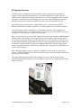
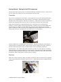
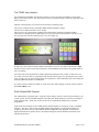
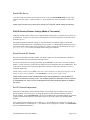
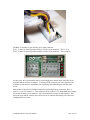
Soundsculpture RC4-TX32D / RC4-RX4-32 Operation Manual R8.1 Jun-2004 JDS / Revised Sep-2004 Soundsculpture - Solid State of the Arts.TM 1-866-258-4577 www.theatrewireless.com Disclaimers Not for Use Where Human Safety May Be At Risk The Soundsculpture RC4 radio system has not been evaluated by any safety agency for use where human safety may be at risk. Soundsculpture Incorporated accepts no liability if RC4 equipment is used for such purposes. Not for Control of Pyrotechnical Devices The Soundsculpture RX4-32 receiver should not be used to control pyrotechnical devices. A brief output surge at the receiver during power-up could trigger these devices. Soundsculpture Incorporated accepts no liability if RC4 equipment is used for such purposes. No 3rd Party Safety Marking is Provided While every attempt has been made to ensure product and user safety, no 3 rd-party safety evaluation has been done on the Soundsculpture TX32D transmitter or RX4-32 receiver. These devices are operated at the user’s own risk and Soundsculpture accepts no liability, either direct or consequential, arising from the use of this equipment. Soundsculpture RC4 Operation Manual Page 2 of 21 SOUNDSCULPTURE RC4-TX32D / RC4-RX4-32 OPERATION MANUAL ...... 1 Disclaimers .................................................................................................................................................... 2 Not for Use Where Human Safety May Be At Risk ................................................................................... 2 Not for Control of Pyrotechnical Devices .................................................................................................. 2 No 3rd Party Safety Marking is Provided .................................................................................................... 2 RC4 System Overview .................................................................................................................................. 4 Getting Started – Setting Up the RC4 Components .................................................................................. 5 Transmitter ................................................................................................................................................. 5 Receivers .................................................................................................................................................... 5 TX32D Transmitter Operation ................................................................................................................... 6 TX32D Keypad Map .................................................................................................................................. 6 RUN & Watch DMX Channel .................................................................................................................... 7 Set DMX Contiguous Channel ................................................................................................................... 8 Edit Individual DMX Channel Assignments .............................................................................................. 8 Save DMX Set-up....................................................................................................................................... 8 Recall DMX Set-up .................................................................................................................................... 9 RX4-32 Receiver/Dimmer Settings (Made at Transmitter) ...................................................................... 9 Select Receiver RX Number ....................................................................................................................... 9 Set RX Channel Assignments..................................................................................................................... 9 Set Other RX Parameters ...........................................................................................................................10 Send RX Config ........................................................................................................................................11 RX4-32 Receiver Operation ........................................................................................................................12 Buttons and Indicators ...............................................................................................................................12 Default Settings .........................................................................................................................................13 Changing the RX Number .........................................................................................................................13 Internal Fuses and Tips About Power Wiring ...........................................................................................13 Receiver Power Connection Diagram .......................................................................................................15 Receiver Auxiliary Data and Control Connection .....................................................................................17 RX4-32-HO High Output Receivers .........................................................................................................17 LAWNII Radio Settings ..............................................................................................................................18 Set System ID ............................................................................................................................................18 Set System Baud Rate ...............................................................................................................................18 Configure Connected TX LAWNII Radio.................................................................................................18 Configure Connected RX LAWNII Radio ................................................................................................18 Additional System Parameters ...................................................................................................................18 Setting the Systems ID Using a Terminal ..................................................................................................19 Using Other Channels................................................................................................................................19 A General Discussion of Radio Reliability ................................................................................................21 Soundsculpture RC4 Operation Manual Page 3 of 21 RC4 System Overview The RC4 system is a fourth generation digital radio control system for operating theatrical lighting. It offers improved performance over previous Soundsculpture systems, with more channels and an enhanced user interface that allows receivers to be configured remotely from the transmitter. Spread-spectrum RF technology ensures a secure, robust and high-speed wireless link between all system components, and does not require special licensing for each user. The TX32D rack mount transmitter is a digital DMX device, compliant with the USITT DMX512/1990 (4uSec) standard. Optional 0 – 10V analog inputs are also available on request. Current firmware provides a maximum of 32 radio dimmer channels. Future upgrades will provide 64 channels. There is no limit to the number of physical receivers in an RC4 system, but 128 unique receiver IDs can be configured by the system. RX4-32 receivers are for use with 12VDC battery power and provide four pulse-width-modulated (PWM) outputs, each capable of delivering continuous power output of 150W into any kind of low-voltage load (typically lamps, but motors and relays can also be operated). Each output can be individually assigned to any RC4 dimmer channel. Outputs assigned to the same channel can be externally wired in parallel. The total power handling of the RX4 is limited to 500W by the capacity of the printed-circuit board traces and connector pins; components are substantially overrated to ensure a long life. RX4-32HO high-output receivers are identical to standard receivers but have a higher power capacity. Each channel of an HO receiver can deliver 250 watts, with a maximum power limit for the entire receiver of 1000W. Fully digital Spread-Spectrum radio allows multiple users in the same RF band to operate simultaneously without interference. Over 60,000 RC4 systems can be separately identified with unique system IDs. Soundsculpture RC4 Operation Manual Page 4 of 21 Getting Started – Setting Up the RC4 Components The RC4 radio control system consists of a rack-mount transmitter, transmitter transceiver, and one or more receivers. Before the system can be used, each item must be properly setup. Transmitter The receiver is a 4-inch deep 3U rack chassis. Control signals are sent to a remote spread-spectrum radio transceiver via a supplied DB-25 cable, and this tranceiver communicates with radio-dimmers on stage. The DB-25 cable carries both power and data to the transceiver. Connect the rack chassis to the transceiver with the cable, and position the transceiver so that it’s top surface is facing out on the theatre stage. Ideally, there should be line-of-sight from the transceiver to each RX4-32 receiver, but this is not mandatory. In ideal conditions, the spread-spectrum radios of the RC4 system can connect through walls and other barriers to a distance of several hundred feet. This range will be reduced, however, by the density of obstructions, other radio activity in the 900Mhz band, and wide-band interference generated by nearby lamps, motors, etc. (including loads connected to RC4 receivers themselves). Connect a DMX source to the DMX input on the transmitter. The RC4-TX32D input is not terminated. A terminated cable or an in-line termination connector must be used if termination is required. In general, a 100-ohm resistor between pins 2 and 3 of a DMX connector will provide adequate termination. Optional analog 0 – 10V control voltage inputs may also be provided. If so, these inputs are activated by setting dipswitch #8 (inside the transmitter) to the ON position. In this mode, the first eight radio channels are directly assigned to the eight analog inputs. These channels are indicated on the LCD as channels AN1 through AN8, and the analog levels are displayed for these channels. Receivers Each receiver must be setup with a battery and lamps or other loads. Please review the Receiver Operation section of this manual before attemping to operate receivers. Output channels must be configured from the transmitter. Soundsculpture RC4 Operation Manual Page 5 of 21 TX32D Transmitter Operation TX32D Keypad Map Set DMX Contiguous Block Start Channel Edit Individual DMX Channel Assignments * Save DMX Set-up Recall DMX Set-up Select Receiver RX Number Set RX Channel Assignments Set Other RX Parameters Send RX Config Set System ID * Set System Baud Rate * Configure Connected TX LAWNII Radio * Configure Connected RX LAWNII Radio * Exit / Run / Watch DMX Channel Move Left / Decrement / No Move Right / Increment / Yes Select/ Enter * not implemented in firmware 1.xxx. Soundsculpture RC4 Operation Manual Page 6 of 21 The TX32D User Interface The TX32D radio transmitter user-interface consists of a 16-key keypad, a 20-character x 2-line LCD display, and a rotary control. The rotary knob can also be pressed as a button, usually the equivalent of the Select / Enter key. Thirteen of the keypad keys are used to select a function or function-group: The top row of buttons invokes transmitter DMX channel assignment settings. The next row of buttons invokes receiver settings. The next row is for system settings, primarily those affecting the operation of the radio modules. The bottom row includes the Exit / Run button to exit any previously invoked function from any row, as well as generic user-interface functions (move left, move right, etc.) In some cases, the screen will show a number of parameters on screen. The Move Left and Move Right buttons move the cursor between these parameters, and the blinking cursor indicates the parameter that is active for editing. The value of the selected parameter is usually adjusted by turning the rotary control. In most cases, the new value is saved by either (1) pressing the Enter button on the keypad, or (2) pressing the rotary control knob. In other cases, as when selecting RX receiver parameters, values immediately take effect and do not requiring additional selection or confirmation. If you have entered a mode by accident, or you do not wish to make changes in a mode you have entered, press Exit & Run to exit. RUN & Watch DMX Channel The TX32D powers up in Run mode. Using the current settings, which are stored in eeprom memory, the system “spools” the selected DMX channels to the radio link. Radio-dimmers store their own settings in local eeprom memory. When they see data of the correct system ID and channel, they respond as programmed. In this mode, the transmitter is also a DMX channel monitor capable of viewing any of up to 512 DMX channels. The rotary control selects the DMX channel being displayed. If the displayed channel is assigned to the radio system, its radio dimmer channel assignment is also displayed. To change the displayed channel more quickly, the Inc / Dec buttons change the current channel in increments of 64 channels up and down. Soundsculpture RC4 Operation Manual Page 7 of 21 Optional analog 0 – 10V control voltage inputs may also be provided. If so, these inputs are activated by setting dipswitch #8 (inside the transmitter) to the ON position. In this mode, the first eight radio channels are directly assigned to the analog inputs. These channels are indicated on the LCD as channels AN1 through AN8, and the analog levels are displayed for these channels. For diagnostics purposes, data spooling can be suspended by pressing the Select key, and resumed by pressing the Run key. Normally, there is no need to suspend or resume this function. NOTE: In the event of a power failure while accessing set-up functions, the unit will come back on in Run mode, using whatever parameters were most recently set. Set DMX Contiguous Channel The quickest and easiest way to assign DMX channels to radio dimmer channels is to use a contiguous block of channels. In this case, only the first channel need be specified. Press Set DMX Start, then select the first DMX channel with the rotary control, then push the rotary control button or Enter key to set it. Thirty-two contiguous DMX channels will now be assigned to radio channels. When first entering this mode, the DMX channel currently being monitored in Run mode is displayed but may be changed before being selected. If the first channel is set higher than 481, assignments will wrap around to channel 0. NOTE: This action overwrites any previously set DMX channel assignments in active use. It does not affect saved set-ups. Edit Individual DMX Channel Assignments Not available in firmware 1.xxx. Save DMX Set-up Four DMX channel assignments can be saved in eeprom. Each set of assignments is called a “DMX Setup”. Set-up “zero” is the active set-up, which is immediately used on power-up and accessed directly from the front panel controls. The others set-ups are DMX Set-Up 1, DMX Set-Up 2, and DMX Set-Up 3. To save the active set-up, press Save DMX Setup. Use the rotary control to select the destination memory location 1-3. Press the Enter key or the rotary knob to execute the save. NOTE: Upon execution, any previously stored settings in the selected memory location are overwritten. Soundsculpture RC4 Operation Manual Page 8 of 21 Recall DMX Set-up To recall a set-up from memory and use it as the active set-up, press Recall DMX Setup. Use the rotary control to select the source memory location 1-3. Press the Enter key or the rotary knob to execute the save. NOTE: Upon execution, the previously active settings are overwritten with the settings from memory. RX4-32 Receiver/Dimmer Settings (Made at Transmitter) Each RX4-32 radio-dimmer watches for two different kinds of data packets: (a) dimmer levels, and (b) setup information. (In either case, the correct system ID must be used to send the packet or the data will not reach the receiver.) All channel assignments and other settings for each radio dimmer and dimmer output are made at the transmitter, then uploaded to the corresponding receiver by radio. A radio-dimmer should be powered on and working when settings for that unit are being made. If this is not the case, the transmitter will report Receiver Not Found on the LCD display when settings are transmitted. Select Receiver RX Number Receivers are identified by their RX number. (In addition, radio receivers and transmitters must share a System ID number that is programmed into the radio itself.) To select a radio-dimmer for set-up programming, press Select RX. Use the rotary control to set the RX number. It is not necessary to press Enter, the displayed value is immediately the current RX number. This is also true for all other receiver parameters BUT these values do not take effect until they are sent to a connected dimmer unit. NOTE: It does no harm to press Enter or the rotary control knob, but it is NOT required to select the RX number or other receiver parameter. Press Exit & Run to exit the receiver set-up screens. NOTE: Some receivers contain customized firmware for special applications. A specific RXnum is required to activate these custom processes. For example, friction-drive dual-motor control is activated by using Rxnum 128. These receivers usually default to the special functions if defaults are loaded at the receiver. Set RX Channel Assignments Each RX4-32 radio-dimmer has four dimmer outputs. These outputs can be assigned to any of the 32 dimmer channels of the radio system. To assign the dimmers of the selected RX number to specific dimmer channels, press Assign RX Chans. The screen will indicate the selected RX number, the currently assigned rf dimmer channels for the four outputs (top line of the LCD), and the corresponding DMX channels. If the rf channel number displayed is preceeded by a “d”, the channel will be configured as a dimmer. If the channel number is preceeded by an “s”, the dimmer will be configured as a switch. (See Switch Mode below for additional information.) Soundsculpture RC4 Operation Manual Page 9 of 21 Note: The corresponding DMX channels will change if the DMX set-up is changed. Set Other RX Parameters In addition to a channel assignment, dimmer outputs have other parameters, as outlined below. These parameters can be edited by pressing Set RX Params and moving the cursor with the Move Left and Move Right keys. Low Level Limit Each dimmer output has a range of 255 dimmer levels, implemented as a PWM (pulse-width modulation) signal at a base frequency of 75Hz. In some cases, large loads draw excessive currents for brief periods when driven with very low power levels. This is because PWM applies full power for a slice of time that is very short (1/256 of 75Hz) for low power and longer as power levels increase (up to 255/255). These short spikes can create electrical noise and interference that is undesirable for both the radio-dimmer and other nearby equipment. For example, a large motor will remain stalled, and a large lamp filament will remain unlit, until a significant amount of energy is delivered. In these states, large transient spikes are generated on each switch-on of the PWM circuit, 75 times each second. The Low Level Limit parameter ensures that power levels below this limit are reduced to zero. For large loads, a recommended Low Level Limit is 15 (15/ 255). For smaller loads a limit of 5 or even zero can be used. The available range is 0 to 31. Switch Mode In some cases, dimmed power levels are not desirable. When turning on a relay or powering a DC device that requires clean constant power, a dimmer output can be set for switch mode. In this case, dimmer levels of 127 or lower will turn the output off, while levels of 128 or higher will turn the output on. Normally – even when using an output in dimmer (not switch) mode – a DMX level of zero will turn the channel fully off and a DMX level of 255 will turn the channel fully on. But in some cases, particularly where analog-to-digital converters are somehow involved, channel levels do not always stay at zero or 255. Any amount of data flutter could cause a dimmer level to be invoked. This is avoided by selecting Switch Mode. Each output can be set for dimmer or switch mode. NOTE: The Soundsculpture TX32D transmitter and RC4 receivers are fully digital, making channel flutter highly unlikely within this system. Nonetheless, flutter could get into DMX data before it arrives at the TX32D transmitter. Soundsculpture RC4 Operation Manual Page 10 of 21 Data Timeout Period (not adjustable in firmware 1.xxx) For various reasons, dimmer data may occasionally be interrupted. When this happens, dimmer outputs will be maintained for one second. The DMX512/1990 specification, as published by the United States Institute for Theatre Technology, requires DMX devices to have a loss of data tolerance of not less than 1 second. The Soundsculpture TX32D transmitter has a loss of data tolerance of just over 1 second at its DMX input. Presuming there are no problems in the wired DMX system controlling the TX32D transmitter, this will have no bearing on radio-dimmer performance. Problems on the DMX line will not invoke the Data Timeout Period in the radio dimmer – in that case, the DMX loss of data tolerance will take effect after one second, and the transmitter will send a dimmer level of zero for all channels. Radio interference problems will cause the radio-dimmer timeout period to take effect. The default Data Timeout Period for RC4 dimmer channels is 1 second and is not user adjustable. Note: The 32-channel TX32D, running firmware 1.xxx, transmits all channel levels a minimum of 60 times per second. DMX data loss will turn off all dimmers after 1 second. Radio interference or other data loss within the Soundsculpture RC4 system will turn off dimmers if no valid data has been received for one second. Although the time period is the same, these events are not related. Send RX Config When the Send RX Config key is pressed, on-screen settings for the selected RX number – dimmer channel assignments, low-level limits, and switch mode settings – are uploaded to the corresponding RC432 radio-dimmer by radio. If a corresponding receiver is not found, the transmitter LCD will report Receiver Not Found. Otherwise, the LCD will report Setup Confirmed. A radio-dimmer will assume a new RX number if it receives a control packet while its ProgRX button is being held down. In this case, the RX value of that packet will become the new RX number for that receiver. Subsequent control packets for this RX number will be accepted and acknowledged. NOTE: The correct System ID must be programmed in the receiver or no data will be accepted, regardless of the state of the ProgRX button. NOTE: Only one radio-dimmer should be programmed to any given RX number. If more than one device sends an acknowledgement at the same time, messages may be garbled. Soundsculpture RC4 Operation Manual Page 11 of 21 RX4-32 Receiver Operation Buttons and Indicators As noted in the previous sections, the RX4-32 radio-dimmer is set-up and controlled remotely from the RC4-TX32D transmitter, using the transmitter’s user interface. This is the only way to configure each output, selecting the dimmer channel, switch or dim mode, and low-level limit. The RX4-32 does have a simple user-interface of its own, however, intended to help with wiring and load testing, and restoring internal settings to default values. Inside the plastic receiver enclosure are two circuit boards: the LAWNII radio board, and the Soundsculpture RX-4 dimmer board. For more information about the rf board, please review the LAWNII User’s Manual. On the dimmer board there are five recessed push buttons, four nearby function LEDs, and four additional LEDs directly connected to the four dimmer outputs. From left to right, the switches and LEDs have these functions: Button: Output 4 Test Button: Output 3 Test Button: Output 2 Test / Power Up Load Default Settings Button: Output 1 Test / Assume RX Number of Incoming Setup Packet Yellow LED: Setup Data Receive Indicator Yellow LED: Dimmer Level Receive Indicator Yellow LED: Processor Operating Properly Blinking Indicator Red LED: Data Error Indicator Reset Button: Hardware Reset / System Restart Soundsculpture RC4 Operation Manual Page 12 of 21 Default Settings To load receiver default settings, hold down Button 2 while powering up the receiver or pressing the Reset Button. This will load the following settings: RX Number = 1 Output 1 Assigned Output 2 Assigned Output 3 Assigned Output 4 Assigned to to to to Channel Channel Channel Channel 1, 2, 3, 4, Dimmer Dimmer Dimmer Dimmer Mode, Mode, Mode, Mode, Lo-Level Lo-Level Lo-Level Lo-Level Limit Limit Limit Limit 5 5 5 5 To change these settings, send a new configuration from the TX32D transmitter, using RX number 1. NOTE: Some receivers contain customized firmware for special applications. These receivers usually default to the special functions and the “standard” defaults above do not apply. Additional documentation for custom features is provided separately. Changing the RX Number To change the RX number of this receiver, send a configuration from the TX32 transmitter using the RX number you desire, and hold down the Output 1 Test / Assume RX Number of Incoming Setup Packet button (4th button from the left) on the receiver while pressing the Send RX Config button on the TX32D transmitter. The RX number of the sent data packet will be assumed by the receiver and stored in eeprom. Subsequent settings sent from the transmitter will be accepted by this receiver without holding any button down. When a receiver accepts new setup data, it displays a short “light show” on its four LEDs as an acknowledgement. It also sends a digital acknowledgement back to the transmitter. This light show is displayed if a setup message comes in on the RX number previously programmed, or if a setup message comes in while the Assume RX Number button is down. In the latter case, the new RX number becomes the currently programmed setting. Note: TX32D firmware 1.xxx does not allow current settings in a receiver to be retrieved and displayed. To reprogram a receiver, you must select the desired settings at the transmitter before sending them. NOTE: Some receivers contain customized firmware for special applications. A specific RXnum is required to activate these custom processes. For example, friction-drive dual-motor control is activated by using Rxnum 128. These receivers usually default to the special functions if defaults are loaded at the receiver. Internal Fuses and Tips About Power Wiring Beside the main power connector on the RX4-32 is a large load fuse. Standard AGC fuses are easily installed in the clips. A 15A fast-blow fuse is provided by the factory. For effective fusing to protect the load and electronics, and reduce safety hazards, one of the following techniques should be used: 1. Reduce the size of the internal fuse to accurately reflect the load size. In this case, the peak total for all four output channels must be considered. Soundsculpture RC4 Operation Manual Page 13 of 21 2. Use external fuses for each individual output channel, ensuring that the peak total does not exceed the internal fuse value. Put the fuse in the positive side of the load circuit and return the circuit back to the positive side of the supply battery. RX4 dimming is done on the negative side. This is the most effective option and is recommended. A small fuse should still be installed on the RX4 board to drive the indicator LEDs. For either case, here are some typical fuse values: 75 watt halogen lamp: draws 6.25A at 12VDC. Use an 8A fuse. 1/4HP 12VDC motor: typically draws 20A when operated smoothly, but could surge to 40A on a fast startup. Use a 25A fastblow fuse and avoid rapid startup (ramp up the power level slowly). It is not recommended to fuse the receiver above 25A. Bench tests have been successful with 40A automotive fuses supplying large banks of incandescent lamps for brief periods. Do not use slow-blow fuses. They do not protect semiconductors in a fault condition. Soundsculpture RC4 Operation Manual Page 14 of 21 Receiver Power Connection Diagram The RX4-32 is remarkably versatile and powerful for its small size. Four outputs deliver pulsewidth-modulated power capable of driving high current motors, lamps, and other inductive or resistive loads. Each output is rated for 200W, equivalent to approximately 16 amps at 12 volts. Output channels can be configured in parallel to deliver higher output currents to large loads. Total receiver power handling is limited by circuit-board traces and connector pins, and should not exceed 600W in total. The recommended AMP pinning tool for these pins is 90124-2. The shells, pins, and pinning tool are available from most electronic component suppliers, including Electrosonic Inc. Channels connected in parallel must have their channel-select and low-level limit switches set identically to avoid one channel taking a heavy load on it's own. Damage resulting from inappropriate configurations will not be covered under warranty. Soundsculpture RC4 Operation Manual Page 15 of 21 The RX4-32 includes a 6-pin auxiliary power input connector: Pins 1, 3, and 5 are wired in parallel with pin 1 on the 10-pin connector. This is +V in. Pins 2, 4, and 6 are wired in parallel with pin 2 on the 10-pin connector. This is GND in. In some cases, the 6-pin connector can be used for high-power battery input, while the 10-pin connector can be used just for outputs. If all pins of both connectors are used, eight wires are available for both power in and dimmer out, equalizing current handling on each end of the circuit. Some models of the RX4-32 include an optional 2-pin backup battery connection. Pin 1 is positive (+), pin 2 is negative (-). This connector can be used as a 12V unregulated power output to external electronics, or be used for a 12V lead-acid battery or large storage capacitor. This allows the logic and RF circuitry in the RC4 receiver to continue functioning even if the loadbearing batteries run down. Soundsculpture RC4 Operation Manual Page 16 of 21 Receiver Auxiliary Data and Control Connection Some RX4 receivers are supplied with an additional 14-pin dual-inline auxiliary data connector. This port provides control lines to external hardware for custom applications. In most cases, custom hardware is provided by Soundsculpture, along with additional documentation. RX4-32-HO High Output Receivers The high output (HO) version of the RX4 receiver features upgraded MOSFET power components and the addition of a cooling fan. Even with these enhancements, high-current power handling is a dangerous game and should not be sustained indefinitely. At 12VDC, a 1000W load demands over 80 Amps of power. The batteries, wires, connections, and fuses required to handle this kind of load are very, very large. To accommodate large loads, both the RX4-32 and the RX4-32-HO feature a 6-pin auxiliary power input connection. Used together with the 10-pin power input/output connector, there are four separate connections in parallel to bring power in, and another four to carry power out to the load. Thus, each wire and connection can carry a more reasonable 20A at 12V. The fuse on RX4 receiver boards cannot carry 80 Amps; neither can the circuit board traces leading to this fuse. When wiring large loads, the positive (+) side of the circuit should be completely external to the RX4 receiver, and it should be carefully and safely fused. A small-gauge wire can be used to bring the positive supply to the RX4 internal control electronics, and the fuse on the RX4 can be 1A or even smaller. The RX4 dimmer introduces pulse-width modulation on the negative (-) side of the circuit, acting as a dimmer on the negative line to the load. This is where you need heavy wire and you should utilize all 4 input and output connections available across both power connectors. If you are using the RX4 as one large dimmer on a single channel, you can wire the outputs of each channel in parallel. For this to work effectively, circuit impedance and resistance for each channel must be closely controlled. More current will flow through shorter circuits, thicker wires, and tighter connections, and this can cause more than a fair share of the total load to be flowing through a particular dimmer channel. This kind of overloading causes oveheating and damage that is not covered under warranty. There are programming issues as well. When ganging output channels together, they must be set to the same data channel, and have the same low-level cut-off and time-out settings. Failure to ensure this could cause one or more channels to disengage while other channels are still operating, causing damage to those channels. Damage caused by not setting parallel channels identically is not covered under warranty. Before using any RX4 receiver at high power levels, please re-read this page and double-check your choices of battery, wire, fuses, and connectors. Bigger is better, as long as connections are solid and secure. Observe caution. Be careful –power loads are operated at your own risk, and Soundsculpture cannot be held responsible in any way whatsoever. Soundsculpture RC4 Operation Manual Page 17 of 21 LAWNII Radio Settings For TX32D firmware 1.xxx, system settings which reside in the radio modules must be set using a terminal, or terminal emulator software. These functions will be supported within the transmitter in future firmware revisions. Set System ID The System ID is a number from 0 to 65535. Values below 1000 are reserved for older 16-channel RC4 systems. New TX32D systems are assigned System IDs of 1000 or higher. Set System Baud Rate The default 32-channel baud-rate is 38.4kbps (kilobits per second). Configure Connected TX LAWNII Radio For TX32D firmware 1.000, LAWNII radio configurations must be created and stored using PC software. This function will be supported within the transmitter in future firmware revisions. Configure Connected RX LAWNII Radio For TX32D firmware 1.000, LAWNII radio configurations must be created and stored using PC software. This function will be supported within the transmitter in future firmware revisions. Additional System Parameters Each LAWNII radio module must be configured for proper operation in the RC4. Each system id should have only one transmitter (or master), and one or more receivers (or slaves). To assist advanced users, the LAWNII User’s Manual accompanies this TX32D manual. LAWNII radios, manufactured by OCI, have recently been upgraded to use eeprom memory, rather than battery-backup memory. Thus, all TX32D systems use only eeprom to store system settings, with no batteries to be replaced or disposed of. Please consult the LAWNII manual for more information about various modes and settings. The radio settings used for the RC4 system create a low-latency master-slave network with no built-in acknowledgements or retries. This is because normal acknowledgement and handshaking protocols Soundsculpture RC4 Operation Manual Page 18 of 21 sacrifice timing for accuracy and can cause unexpected delays in data transmission. For real-time control systems, different techniques must be used. The microprocessors at each end of the RC4 dimmer control system use real-time cyclical-redundancy to ensure reasonable accuracy without introducing varying delays. The coding for this technique is proprietary to the Soundsculpture RC4 system. LAWNII settings for the RC4 system are on the following page. Settings can be made using an RS232 terminal, or a computer running a terminal emulation program. It is important that the terminal emulator be able to send control characters (i.e. Ctrl-C). The Microsoft Windows Operating system comes bundled with the HyperTerminal terminal emulation program. It can be used to configure LAWNII radios. Be sure to use the following settings: Direct connect to any available COM port VT100 emulation Control keys act as Terminal keys (very important) Standard ASCII character set Additional information about connecting to the LAWNII radio with HyperTerminal is included in the LAWNII radio. Setting the Systems ID Using a Terminal The System ID of each LAWNII radio must be the same for the transmitter and all receivers used in a given system. If you own and use more than one RC4 radio system, you may wish to move receivers between systems. This can be done by changing only one parameter in the LAWNII radio. All other settings can be left unchanged and to not have to be re-entered: <connect at 38400 baud> <Ctrl-C three times to enter command mode> SYS <use number for your system> SAVE <allow at last 500ms for save to complete> TRANS To avoid conflicts, Soundsculpture RC4 dimmer systems use System IDs of 1000 or higher. Please do not use lower system IDs with 32-channel RC4 systems. Using Other Channels At the factory, all RC4 :LAWNII transceivers are setup on radio channel 2 (CHA 2). The LAWNII radio supports three channels (1, 2, and 3) and any of these may be used with the RC4 system. If another channel is used, this setting must be changed at every LAWNII in the system – the transmitter and each receiver. Note: If you are using multiple RC3 systems and experience reduced refresh rates as they try to share radio bandwidth, try changing the channel of one system. Soundsculpture RC4 Operation Manual Page 19 of 21 Complete LAWNII Configurations for the RC4 System For a single Transmitter (TX) LAWNII: AUTOLF ON ABAUD 38400 * MYC RC4TX DFCN RC4TX SYS <number for your system> CHA 2 <other channels can be used> PACTIME A 1 BE E 0 UNPROTO RC4RX LAWNGRAM ON TRANSGRA ON LCALLS RC4TX PACLEN 0 TIMEOUT 0 SAVE <allow at last 500ms for save to complete> TRANS For any number of Receiver (RX) LAWNIIs: AUTOLF ON ABAUD 38400 * MYC RC4RX DFCN RC4RX SYS <use number for your system> CHA 2 <other channels can be used> PACTIME A 1 BE E 0 UNPROTO RC4TX LAWNGRAM ON TRANSGRA ON LCALLS RC4RX PACLEN 0 TIMEOUT 0 SAVE <allow at last 500ms for save to complete> TRANS * If you are not already connected at 38400 baud, you will have to reconnect to the LAWNII radio at this speed after setting ABAUD 38400. New LAWNII radios are configured at the default baud rate of 9600, so initial connections must be made at this speed. The RC4 dimmer system requires a baud rate of 38400. The transmitter and any associated receivers MUST have the same SYS and CHA settings. Soundsculpture RC4 Operation Manual Page 20 of 21 A General Discussion of Radio Reliability The Soundsculpture RC4 system is exceptionally reliable when properly set up. The most critical factor when using the system is transceiver placement, since these units house the high-frequency spreadspectrum antenna. Consider the following guidelines when installing the transmitter and all receivers: - The transceiver antenna surfaces (transmitter and all receivers) must not be obstructed by metal surfaces. Remember that lead-acid batteries have lead inside, and count as an obstruction. - Internal antennas are most effective when facing other units in the system (i.e. receivers should face towards the transmitter and vice-versa). Alternatively, all antennas can face in the same direction (up, down, into a wing, etc.); reflections off ceilings and walls usually result in a solid radio link. - Avoid many solid obstructions between the transmitter and receivers, especially as the distance between them is extended. In an environment with a continuous solid reflective surface (like a ceiling) and a minimum of obstructions (no walls),RC4 spread spectrum receivers work flawlessly over an 80,000 square foot area. With transceivers facing each other directly through an unobstructed line-of-sight, point to point range can exceed 3000 feet. A typical theatre environment with the transmitter transceiver secured to overhead piping, and receivers on stage (less than 100 feet away) is considered ideal. No user-detectable errors should occur, regardless of the receiver time-out period and moderate amounts of electrical noise from other equipment. Flying setpieces in the house area should also perform correctly via reflections off the stage floor (i.e. the chandelier in The Phantom of the Opera). Errors will generally not sustain more than 1/60th of a second, the maximum amount of time before every channel has been reset by redundant data re-transmissions. However, if errors are caused by consistent multi-path interference or insufficient signal level, errors may persist or repeat. The RC4 software protocol has been designed to be tolerant of the kinds of interference and interruptions that are typical of RF data links. Moderate interference should not cause user-detectable errors. Soundsculpture - Solid State of the Arts.TM Contact: James Smith Soundsculpture Incorporated 1-866-258-4577 [email protected] www.theatrewireless.com Soundsculpture RC4 Operation Manual Page 21 of 21