1
AS-i 3.0 Command Interface
Description of commands
AS-i 3.0 Specification
Revision date: 2007-12-3
Subject to modifications.
Reproduction, duplication and/or translation is not permitted.
Products, symbols and names are normally quoted here without reference to existing patent, registered utility models or
trademarks.
The lack of any such reference does not justify the assumption
that a product, symbol or name is free of rights.
© Euchner GmbH + Co. KG
Kohlhammerstraße 16
D-10771 Leinfelden-Echterdingen
AS-i 3.0 Command Interface
Table of Contents
Table of Contents
AS-i 3.0 Command Interface
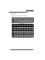
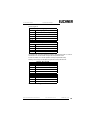
Description of commands........................................................ 1
1
Introduction .............................................................................................. 6
2
Structure of the Command Interface ...................................................... 7
3
List of all Commands ............................................................................... 9
4
Commands of the Command Interface ................................................ 12
4.1
AS-i 16-bit data ................................................................................................... 12
4.1.1
Overview of the commands ............................................................................... 12
4.1.2
Read 1 16-bit Slave in.Data (RD_7X_IN) .......................................................... 12
4.1.3
Write 1 16-bit Slave out. Data (WR_7X_OUT) .................................................. 13
4.1.4
Read 1 16-bit Slave out. Data (RD_7X_OUT) ................................................... 13
4.1.5
Read 4 16-bit Slave in. Data (RD_7X_IN_X) ..................................................... 14
4.1.6
Write 4 7.3 Slave out. Data (WR_7X_OUT_X) .................................................. 14
4.1.7
Read 4 7.3 Slave out. Data (RD_7X_OUT_X) .................................................. 15
4.1.8
Read 16 channels 16-bit Slave in. Data (OP_RD_16BIT_IN_CX) .................... 15
4.1.9
Write 16 channels 16-bit slave out. Data (OP_WR_16BIT_IN_CX) .................. 16
4.2
Commands acc. to Profile S-7.4/S-7.5 .............................................................. 16
4.2.1
Overview of the commands ............................................................................... 16
4.2.2
WR_74_75_PARAM .......................................................................................... 16
4.2.3
RD_74_75_PARAM ........................................................................................... 17
4.2.4
RD_74_75_ID .................................................................................................... 18
4.2.5
RD_74_DIAG ..................................................................................................... 19
4.3
Acyclic commands ............................................................................................. 19
4.3.1
Overview of the commands ............................................................................... 19
4.3.2
WRITE_ACYCLIC_TRANS ............................................................................... 19
4.3.3
READ_ACYCLIC_TRANS ................................................................................. 21
4.3.3.1
Structure of the response buffer ..................................................................... 21
4.3.3.2
Command 1: Read „S-7.4 ID String" ............................................................... 23
4.3.3.3
Command 2: Read „S-7.4 Diag String" ........................................................... 23
4.3.3.4
Command 3: Read „S-7.4 Param String" ........................................................ 23
4.3.3.5
Command 4: Write „S-7.4 Param String“ ........................................................ 23
4.3.3.6
Command 5: „Transfer S-7.5“ ......................................................................... 24
4.3.3.7
Command 6: Read „Cyclical S-7.5 16-bit configuration“ ................................. 24
4.3.3.8
Command 7: Read „Safety Monitor sorted acc. to OSSD“ ............................. 24
4.3.3.9
Command 8: Read „Safety Monitor unsorted by OSSD“ ................................ 26
4.3.3.10
Command 9: „reserved“ .................................................................................. 26
4.3.3.11
Commands 10 - 13: Safety unit diagnosis and shutdown-history ................... 27
4.3.3.12
Command 14: "Diagnosis / shutdown-history" ................................................ 28
4.3.3.13
Command 15: "Safety Status" ......................................................................... 30
Subject to reasonable modifications due to technical advances
Kohlhammerstraße 16, D-70771 Leinfelden-Echterdingen
Id.-No.: 102875 Issue date - 03.12.07
EUCHNER GmbH + Co. KG
Tel. +49/711/7597-0, Fax +49/711/753316
3
AS-i 3.0 Command Interface
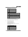
4.4
4.4.1
4.4.2
4.4.3
4.4.4
4.4.5
4.4.6
4.4.7
4.4.8
4.4.9
4.4.10
4.4.11
4.4.12
4.4.13
4.4.14
4.4.15
4.5
4.5.1
4.5.2
4.5.3
4.5.4
4.5.5
4.5.6
4.5.7
4.5.8
4.5.9
4.5.10
4.5.11
4.5.12
4.5.13
4.5.14
4.5.15
4.5.16
4.6
4.6.1
4.6.2
4.6.3
4.6.4
4.6.5
4.6.6
4.6.7
4.6.8
4.6.9
4.6.10
4.6.11
4.6.12
4.6.13
4.6.14
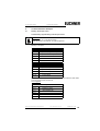
AS-i Diagnosis .................................................................................................... 31
Overview of the commands ............................................................................... 31
Get Lists and Flags (Get_LPS, Get_LAS, Get_LDS, Get_Flags)
(GET_LISTS) ..................................................................................................... 31
Get Flags (GET_FLAGS) ................................................................................... 33
Get Delta List (GET_DELTA) ............................................................................. 34
Get list of corrupted Slaves (GET_LCS and GET_LCS_R6 (6CH)) .................. 35
Get list of activated Slaves (GET_LAS) ............................................................. 35
Get list of detected AS-i Slaves (GET_LDS) ...................................................... 36
Get list of peripheral faults (GET_LPF) .............................................................. 37
Get list of offline Slaves (GET_LOS) ................................................................. 37
Set list of offline Slaves (SET_LOS and SET_LOS_R6 (6Dh)) ......................... 38
Get transm.err.counters (GET_TECA) ............................................................... 39
Get transm.err.counters (GET_TECB) ............................................................... 40
Get transm.err.counters (GET_TEC_X) ............................................................. 41
Read fault detector (READ_FAULT_DETECTOR) ............................................ 41
Read list of duplicate addresses (READ_DUPLICATE_ADDR) ........................ 42
Configuration of AS-i Master ............................................................................. 43
Overview of the commands ............................................................................... 43
Set operation mode (SET_OP_MODE: Set_Operation_Mode) ......................... 43
Store actual configuration (STORE_CDI) .......................................................... 44
Read actual configuration (READ_CDI) ............................................................. 45
Set permanent configuration (SET_PCD) .......................................................... 45
Get extended permanent configuration (GET_PCD) ......................................... 46
Set list of projected slaves (SET_LPS and SET_LPS_R6 (6Bh)) ...................... 47
Get list of projected slaves (GET_LPS) ............................................................. 48
Store actual parameters (STORE_PI) ............................................................... 48
Write parameter (WRITE_P) .............................................................................. 49
Read parameter (READ_PI: Read_Parameter) ................................................. 49
Set permanent parameter (SET_PP) ................................................................. 50
Get permanent parameter (GET_PP) ................................................................ 50
Set auto address enable (SET_AAE) ................................................................ 51
Change slave address (SLAVE_ADDR) ............................................................ 51
Write AS-i slave extended ID1 (WRITE_XID1) .................................................. 52
Other commands ................................................................................................ 53
Overview of the commands ............................................................................... 53
IDLE ................................................................................................................... 53
Read input data image (READ_IDI) ................................................................... 54
Write output data image (WRITE_ODI) ............................................................. 54
Read output data image (READ_ODI) ............................................................... 55
Set offline mode (SET_OFFLINE) ..................................................................... 55
Release data exchange (SET_DATA_EX) ........................................................ 56
Rewrite DPRAM (REWRITE_DPRAM) .............................................................. 56
BUTTONS .......................................................................................................... 57
FP_PARAM ........................................................................................................ 57
FP_DATA ........................................................................................................... 58
EXT_DIAG ......................................................................................................... 58
RD_EXT_DIAG .................................................................................................. 59
Inverter ............................................................................................................... 60
Subject to reasonable modifications due to technical advances
4
Table of Contents
Kohlhammerstraße 16, D-70771 Leinfelden-Echterdingen
Id.-No.: 102875 Issue date - 03.12.07
EUCHNER GmbH + Co. KG
Tel. +49/711/7597-0, Fax +49/711/753316
AS-i 3.0 Command Interface
Table of Contents
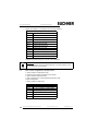
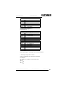
4.6.15
Write Flag .......................................................................................................... 60
4.6.16
Read Flag .......................................................................................................... 61
4.6.17
READ_MFK_PARAM ........................................................................................ 61
4.7
Functional Profiles ............................................................................................. 62
4.7.1
"Safety at Work" List 1 ....................................................................................... 62
4.7.1.1
Slave list with EcFlags .................................................................................... 62
4.7.1.2
Slave list without EcFlags ............................................................................... 64
4.7.2
"Safety at Work" Monitor diagnosis ................................................................... 64
4.7.3
Setting of the AS-i diagnosis ............................................................................. 65
4.7.4
Enhanced diagnosis .......................................................................................... 67
4.7.5
Integrated AS-i Sensors: Warnings ................................................................... 70
4.7.6
Integrated AS-i sensors: Availability .................................................................. 71
4.7.7
Language-select ................................................................................................ 72
4.7.8
Replacement of Safety Slaves input data .......................................................... 73
4.7.9
List of Safety Slaves .......................................................................................... 74
5
5.1
5.2
5.3
5.4
Command Interface Examples .............................................................. 75
Reading 16-bit input values .............................................................................. 75
Store current configuration to the AS-i master ............................................... 76
Store new configuration for all slaves ............................................................. 80
Example for the readout of the safety monitor with ACYC_TRANS .............. 88
6
Appendix: Code description ................................................................. 94
7
We Are Interested in Your Opinion! ..................................................... 97
Subject to reasonable modifications due to technical advances
Kohlhammerstraße 16, D-70771 Leinfelden-Echterdingen
Id.-No.: 102875 Issue date - 03.12.07
EUCHNER GmbH + Co. KG
Tel. +49/711/7597-0, Fax +49/711/753316
5
AS-i 3.0 Command Interface
1
Introduction
Introduction
The AS-i gateways integrate the AS-i slaves into the upstream fieldbus. Each upstream fieldbus (f.e. Modbus/TCP, CANopen, or PROFIBUS) has its unique possibilities to access cyclically and acyclically data. The gateway polls as an AS-i
master all the slaves on the AS-i circuit. The result of these polls the gateway
keeps in its internal state RAM as images of the inputs, outputs, parameters, and
status. These images are available for use on the upstream fieldbus with their specific access methods. The images of the Modbus/TCP to AS-i gateway are available with Modbus Read and Write function calls on different Modbus registers. The
main manual (command: insert cross reference) describes this in detail. CANopen
provides this access with PDOs for cyclical access and SDOs for acyclical access.
The access to the images of the gateway is easy to configure on the upstream
fieldbus and in most applications sufficient. However, the complete functionality of
the gateway is available with the command interface. If you want to read the diagnosis string of an AS-i tuner (slave with 7.4 profile), you will need the command
interface to call the WRITE_ACYC_DATA and READ_ACYC_DATA commands.
The command interface is avaible in a special image. A command is called by writing into this image and the command result is avaible with a read to this image.
The manual "AS-i 3.0 Command Interface" describes commands of the AS-i
3.0 Command Interface. A description of an AS-i Master is not included.
Please refer to the corresponding manual of your AS-i Master for further information.
Please view the documentation of the respective device for further, devicespecific information about the kind of the access to the command interface.
Subject to reasonable modifications due to technical advances
6
Kohlhammerstraße 16, D-70771 Leinfelden-Echterdingen
Id.-No.: 102875 Issue date - 3.12.2007
EUCHNER GmbH + Co. KG
Tel. +49/711/7597-0, Fax +49/711/753316
AS-i 3.0 Command Interface
2
Structure of the Command Interface
Structure of the Command Interface
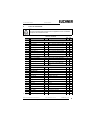
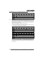
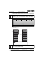
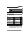
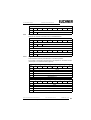
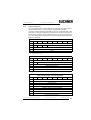
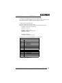
The command interface has the following structure shown in table 1 and table 2.
Table 1
command request
byte
27
26
T
O
25
1
2
24
23
22
21
20
command
circuit
3
request parameter byte 1
…
…
36
request parameter byte 34
Bit T in the command interface is the toggle bit. The toggle bit is only necessary
in the case of interfaces which transfer the data cyclically.
The execution of a command of the command interface is declined, if the number
of the transferred parameters is too small, this could happen when the command
interface is too small or the tegram is too short.
Circuit selects the AS-i circuit. Circuit = 0 selects the first circuit.
Bit LO is the list order bit. The commands for reading and writinig slave lists support two different sorting schemas.
LO = 0 selects the Euchner schema.
LO = 1 selects the Siemens schema (the sequence of the bits in the slave lists
bytes is inverse).
Parameter byte n is the nth parameter of the command. The number of parameters is different for different commands. It is not necessary to set the additional parameter bytes to 0 in the command interface, if a command does not use the
maximum number of parameter bytes (36)
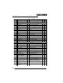
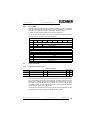
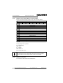
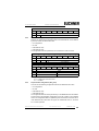
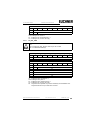
Table 2
command response
byte
27
26
1
2
25
24
23
22
21
20
command (mirrored)
T
3
result
response byte 1
…
…
36
response byte 34
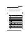
There is the reflected command byte and the toggle bit of the request in the response. The execution of the command returns its result in the seven least significant bits of byte 2 of the response. 0 signals execution of the command without
an error. The table result codes shows all possible result codes.
Subject to reasonable modifications due to technical advances
Kohlhammerstraße 16, D-70771 Leinfelden-Echterdingen
Id.-No.: 102875 Issue date - 3.12.2007
EUCHNER GmbH + Co. KG
Tel. +49/711/7597-0, Fax +49/711/753316
7
AS-i 3.0 Command Interface
Structure of the Command Interface
Please note that possibly some controls can exchange the high and low byte
on the field bus with word orientated access to the command interface.
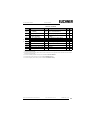
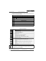
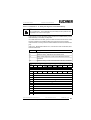
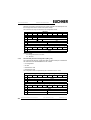
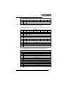
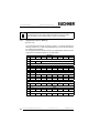
Result codes
Name
Value
Description
OK
0016
execution without fault
HI_NG
1116
general fault
HI_OPCODE
1216
illegal value in command
HI_LENGTH
1316
length of the command interface is too short1
HI_ACCESS
1416
no access right
EC_NG
2116
general fault
EC_SND
2216
slave (source addr) not detected
EC_SD0
2316
slave 0 detected
EC_SD2
2416
slave (target addr) not decteced
EC_DE
2516
delete error
EC_SE
2616
set error
EC_AT
2716
address temporary
EC_ET
2816
extended ID1 temporary
EC_RE
2916
read (extended ID1) error
1. The length of the command interface in the I/O-data area respectively the length of the DPV1 requests is too short
Subject to reasonable modifications due to technical advances
8
Kohlhammerstraße 16, D-70771 Leinfelden-Echterdingen
Id.-No.: 102875 Issue date - 3.12.2007
EUCHNER GmbH + Co. KG
Tel. +49/711/7597-0, Fax +49/711/753316
AS-i 3.0 Command Interface
3
List of all Commands
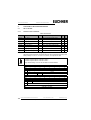
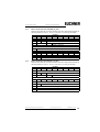
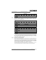
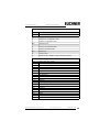
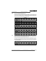
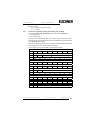
List of all Commands
!!!
The most of the described commands can be applied to all AS-i 3.0 Masters.
Exceptions are indicated in footers.
Values for command
!
Req
Len
Res
Len
read 1 16-bit slave profile in.data
3
10
write 1 16-bit slave profile out.data
11
2
5216
read 1 16-bit slave profile out.data
3
10
RD_7X_IN_X
5316
read 4 16-bit slave profile in.data
3
34
WR_7X_OUT_X
5416
write 4 16-bit slave profile out.data
35
2
page 15
RD_7X_OUT_X
5516
read 4 16-bit slave profile out.data
3
34
page 15
OP_RD_16BIT_IN_CX
4C16 read 16 channels 16-bit slave in.data
3
34
page 16
OP_WR_16BIT_IN_CX
4D16 write 16 channels 16-bit slave in.data
36
2
page 16
Commands acc. to Profile S-7.4/S-7.5
page 16
WR_74_75_PARAM
5A16
write S-7.4/S-7.5-slave parameter
≥6
2
page 17
RD_74_75_PARAM
5B16
read S-7.4/S-7.5-slave parameter
4
≥3
page 18
RD_74_75_ID
5C16 read S-7.4/S-7.5-slave ID string
4
≥3
page 19
RD_74_DIAG
5D16 read S-7.4/S-7.5-slave diagnosis
string
4
≥3
page 19
Acyclic commands
page 19
WRITE_ACYC_TRANS
4E16
write acyclic transfer
≥7
2
page 21
READ_ACYC_TRANS
4F16
read acyclic transfer
5
≥2
page 31
AS-i Diagnosis
page 31
GET_LISTS
3016
get LDS/LAS/LPS flags
2
29
page 33
GET_FLAGS
4716
get flags
2
5
page 34
GET_DELTA
5716
get list of config. diff.
2
10
page 35
GET_LCS
6016
get LCS
2
10
page 35
GET_LAS
4516
get LAS
2
10
page 36
GET_LDS
4616
get LDS
2
10
page 37
GET_LPF
3E16
get LPF
2
10
page 37
GET_LOS
6116
get LOS
2
10
page 38
SET_LOS
6216
set LOS
10
2
page 39
GET_TECA
6316
get transm.err.counters
2
34
page 40
GET_TECB
6416
get transm.err.counters
2
34
page 41
GET_TEC_X
6616
get transm.err.counters
4
≥3
page 41
READ_FAULT_DETECTOR1 1016
read Fault_Detector
2
4
see page
Command
Value
Meaning
page 12
AS-i 16-bit data
page 12
page 13
RD_7X_IN
5016
WR_7X_OUT
5116
page 13
RD_7X_OUT
page 14
page 14
Subject to reasonable modifications due to technical advances
Kohlhammerstraße 16, D-70771 Leinfelden-Echterdingen
Id.-No.: 102875 Issue date - 3.12.2007
EUCHNER GmbH + Co. KG
Tel. +49/711/7597-0, Fax +49/711/753316
9
AS-i 3.0 Command Interface
List of all Commands
Values for command
see page
!
!
Command
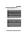
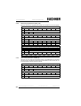
page 42 READ_DUPLICATE_ADDR2
Meaning
1116
read list of duplicate addresses
Req
Len
Res
Len
2
10
page 43
Configuration of AS-i Master
page 43
SET_OP_MODE
0C16 set Operation_Mode
3
2
page 44
STORE_CDI
0716
store Actual_Configuration
2
2
page 45
READ_CDI
2816
read Actual_Configuration
3
4
page 45
SET_PCD
2516
set Permanent_Config
5
2
page 45
GET_PCD
2616
get Permanent_Config
3
4
page 47
SET_LPS
2916
set LPS
11
2
page 48
GET_LPS
4416
get LPS
2
10
page 48
STORE_PI
0416
store Actual_Parameter
2
2
page 49
WRITE_P
0216
write Parameter
4
3
page 49
READ_PI
0316
read Parameter
3
3
page 50
SET_PP
4316
set Permanent_Parameter
4
2
page 50
GET_PP
0116
get Permanent_Parameter
3
3
page 51
SET_AAE
0B16
set Auto_Address_Enable
3
2
page 53
SLAVE_ADDR
0D16 change Slave_Address
4
2
page 52
WRITE_XID1
3F16
write Extended_ID-Code_1
3
2
page 53
Other commands
page 53
IDLE
0016
no request
2
2
page 54
READ_IDI
4116
read IDI
2
36
page 54
WRITE_ODI
4216
write ODI
34
2
page 55
READ_ODI
5616
read ODI
2
34
page 55
SET_OFFLINE
0A16
set Off-Line_Mode
3
2
page 56
SET_DATA_EX
4816
set Data_Exchange_Active
3
2
page 56
REWRITE_DPRAM3
7816
rewrite DPRAM
3
3
page 56
BUTTONS
7516
disable push buttons
3
2
FP_PARAM
7D16 functional Profile Parameter
≥3
≥2
4
3
page 57
page 72
language-select
0E16
set display language
page 73
replacement of safety
slaves input data
0F16
set safety input slave "interpretation
data"
4
2
7E16
functional profile data
≥3
≥2
page 58
FP_DATA
page 62
"Safety at Work" list
0016
slaves with released safety function,
response contains EcFlags
3
8
page 64
"Safety at Work" list
0D16 slaves with released safety function,
response doesn‘t contain EcFlags
3
6
page 64
"Safety at Work" diagnosis
0216
monitor diagnosis
5
n
page 70
integrated AS-i sensors:
Warnings
0316
sensors with deleted D1 bit
3
10
Subject to reasonable modifications due to technical advances
10
Value
Kohlhammerstraße 16, D-70771 Leinfelden-Echterdingen
Id.-No.: 102875 Issue date - 3.12.2007
EUCHNER GmbH + Co. KG
Tel. +49/711/7597-0, Fax +49/711/753316
AS-i 3.0 Command Interface
List of all Commands
Values for command
see page
Value
Meaning
Req
Len
Res
Len
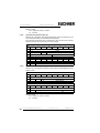
page 71
Integrated AS-i sensors:
Availability
0416
sensors with deleted D2 bit
3
6
page 72
language-select
0E16
read display language
3
3
page 73
replacement of safety
slaves input data
0F16
read safety input slave "interpretation data"
3
4
list of safety slaves
1016
read addresses of safety slaves
3
6
7116
ExtDiag generation
6
2
page 74
!
!
Command
page 58
EXT_DIAG4
page 59
RD_EXT_DIAG5
7B16 read ExtDiag Settings
2
7
page 60
INVERTER
7C16 configure inverter slaves
12
4
page 60
MB_OP_CTRL_WR_FLAGS
8516
write flags
≥5
2
page 61
MB_OP_CTRL_RD_FLAGS
8616
read flags
4
≥3
page 61
RD_MFK_PARAM
5916
read SEW MFK21 parameter
6
≥3
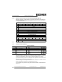
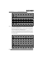
1. The command READ_FAULT_DETECTOR is valid only for the use with masters which support this function. Please refer to the user manual of
the master for further information.
2. The command READ_DUPLICATE_ADDR is valid only for the use with masters which support this function. Please refer to the user manual of
the master for further information.
3. The command REWRITE_DPRAM is valid only for the use with AS-i 3.0 Module OEM Master
4. The command EXT_DIAG is valid only for the use with AS-i 3.0 PROFIBUS Gateways
5. The command RD_EXT_DIAG is valid only for the use with AS-i 3.0 PROFIBUS Gateways
Subject to reasonable modifications due to technical advances
Kohlhammerstraße 16, D-70771 Leinfelden-Echterdingen
Id.-No.: 102875 Issue date - 3.12.2007
EUCHNER GmbH + Co. KG
Tel. +49/711/7597-0, Fax +49/711/753316
11
AS-i 3.0 Command Interface
Commands of the Command Interface
4
Commands of the Command Interface
4.1
AS-i 16-bit data
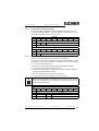
4.1.1
Overview of the commands
Values for command
see page
Command
Value
Meaning
Req
Len
Res
Len
10
page 12
RD_7X_IN
5016
read 1 16-bit slave profile in.data
3
page 13
WR_7X_OUT
5116
write 1 16-bit slave profile out.data
11
2
page 13
RD_7X_OUT
5216
read 1 16-bit slave profile out.data
3
10
page 14
RD_7X_IN_X
5316
read 4 16-bit slave profile in.data
3
34
page 14
WR_7X_OUT_X
5416
write 4 16-bit slave profile out.data
35
2
page 15
RD_7X_OUT_X
5516
read 4 16-bit slave profile out.data
3
34
page 15
OP_RD_16BIT_IN_CX
4C16
read 16 channels 16-bit slave in.data
3
34
page 16
OP_WR_16BIT_IN_CX
4D16
write 16 channels 16-bit slave in.data
36
2
4.1.2
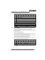
Read 1 16-bit Slave in.Data (RD_7X_IN)
With this command, the four 16-bit channels of an AS-i input slave according to the
slave profile (S-7.3, S-7.4, S-7.5, S-7.A.8, S.A.9, S-7.A.A) can be read.
A-Slaves map the data on channels 1 and 2.
B-Slaves map the data on channels 3 and 4.
Only values among 1 and 31 can be taken as a slave address.
Request
byte
7
2
T
–
2
6
2
5
24
1
2
23
22
21
20
21
20
5016
3
–
circuit
0
slave address
Response
byte
27
26
1
2
24
23
22
5016
T
3
result
channel 1, high byte
…
…
10
channel 4, low byte
Subject to reasonable modifications due to technical advances
12
25
Kohlhammerstraße 16, D-70771 Leinfelden-Echterdingen
Id.-No.: 102875 Issue date - 3.12.2007
EUCHNER GmbH + Co. KG
Tel. +49/711/7597-0, Fax +49/711/753316
AS-i 3.0 Command Interface
4.1.3
Commands of the Command Interface
Write 1 16-bit Slave out. Data (WR_7X_OUT)
With this command, the four 16-bit channels of an AS-i output slave according to
the slave profile (S-7.3, S-7.4, S-7.5, S-7.A.8, S.A.9, S-7.A.A) can be written.
Request
byte
7
2
T
–
2
6
2
5
24
1
2
23
22
21
20
21
20
5116
3
–
circuit
0
slave address
4
channel 1, high byte
…
…
11
channel 4, low byte
Response
byte
27
26
25
24
1
2
4.1.4
23
22
5116
T
result
Read 1 16-bit Slave out. Data (RD_7X_OUT)
With this command, the four 16-bit channels of an AS-i output slave according to
the slave profile (S-7.3, S-7.4, S-7.5, S-7.A.8, S.A.9, S-7.A.A) can be read.
Request
byte
27
26
25
24
1
2
23
22
21
20
21
20
5216
T
3
–
–
circuit
0
slave address
Response
byte
2
7
26
1
2
25
24
23
22
5216
T
3
result
channel 1, high byte
…
…
10
channel 4, low byte
Subject to reasonable modifications due to technical advances
Kohlhammerstraße 16, D-70771 Leinfelden-Echterdingen
Id.-No.: 102875 Issue date - 3.12.2007
EUCHNER GmbH + Co. KG
Tel. +49/711/7597-0, Fax +49/711/753316
13
AS-i 3.0 Command Interface
4.1.5
Commands of the Command Interface
Read 4 16-bit Slave in. Data (RD_7X_IN_X)
With this command, the four 16-bit channels of 4 AS-i input slaves with successive
addresses according to slave profile (S-7.3, S-7.4, S-7.5, S-7.A.8, S.A.9, S-7.A.A)
can be read.
Request
byte
27
26
25
24
1
2
23
22
21
20
5316
T
3
–
–
circuit
0
1st slave address
Response
byte
2
7
26
25
24
1
2
22
21
20
5316
T
result
3
4.1.6
23
1st slave, channel 1, high byte
…
…
34
4th slave, channel 4, low byte
Write 4 7.3 Slave out. Data (WR_7X_OUT_X)
With this command the four 16-bit channels of four AS-i output slaves with successive addresses according to slave profile (S-7.3, S-7.4, S-7.5, S-7.A.8, S.A.9, S7.A.A) can be written.
Request
byte
27
26
25
24
1
2
23
22
21
20
5416
T
3
–
–
circuit
0
4
1st slave address
1st slave, channel 1, high byte
…
…
35
4th slave, channel 4, low byte
Response
byte
2
7
2
6
1
2
24
23
22
21
20
5416
T
Subject to reasonable modifications due to technical advances
14
2
5
Kohlhammerstraße 16, D-70771 Leinfelden-Echterdingen
result
Id.-No.: 102875 Issue date - 3.12.2007
EUCHNER GmbH + Co. KG
Tel. +49/711/7597-0, Fax +49/711/753316
AS-i 3.0 Command Interface
4.1.7
Commands of the Command Interface
Read 4 7.3 Slave out. Data (RD_7X_OUT_X)
With this command, the four 16-bit channels of four AS-i output slaves with successive addresses according to slave profile (S-7.3, S-7.4, S-7.5, S-7.A.8, S.A.9,
S-7.A.A) can be read.
Request
byte
27
26
25
24
1
2
23
22
21
20
5516
T
3
–
–
circuit
0
1st slave address
Response
byte
2
7
26
25
24
1
2
22
21
20
5516
T
result
3
4.1.8
23
1st slave, channel 1, high byte
…
…
34
4th slave, channel 4, low byte
Read 16 channels 16-bit Slave in. Data (OP_RD_16BIT_IN_CX)
With this command, the 16 channels of the 16-bit input-data for slaves with successive addresses according to slave profile (S-7.3, S-7.4, S-7.5, S-7.A.8, S.A.9,
S-7.A.A) can be read.
Request
Byte
27
26
25
24
1
2
23
22
21
20
22
21
20
4C16
T
–
circuit
3
1. slave
4
1. channel
Response
Byte
2
7
2
1
2
6
2
5
24
23
4C16
T
result
3
1. slave, channel 1, high byte
4
1. slave, channel 1, low byte
…
…
33
16. channel, high byte
34
16. channel, low byte
Subject to reasonable modifications due to technical advances
Kohlhammerstraße 16, D-70771 Leinfelden-Echterdingen
Id.-No.: 102875 Issue date - 3.12.2007
EUCHNER GmbH + Co. KG
Tel. +49/711/7597-0, Fax +49/711/753316
15
AS-i 3.0 Command Interface
4.1.9
Commands of the Command Interface
Write 16 channels 16-bit slave out. Data (OP_WR_16BIT_IN_CX)
With this command, the 16 channels of the 16-bit input-data for slaves with successive addresses according to slave profile (S-7.3, S-7.4, S-7.5, S-7.A.8, S.A.9,
S-7.A.A) can be written.
Request
Byte
27
26
25
24
1
2
23
22
21
20
21
20
4D16
T
circuit
3
1. slave
4
1. channel
5
1. slave, 1. channel, high byte
6
1. slave, 1. channel, low byte
…
…
35
16. channel, high byte
36
16. channel, low byte
Response
Byte
2
7
26
25
24
1
2
23
22
4D16
T
result
4.2
Commands acc. to Profile S-7.4/S-7.5
4.2.1
Overview of the commands
Values for command
Req
Len
Res
Len
see page
Command
Value
Meaning
page 16
WR_74_75_PARAM
5A16
write S-7.4/S-7.5-slave parameter
≥6
2
page 17
RD_74_75_PARAM
5B16
read S-7.4/S-7.5-slave parameter
4
≥3
page 18
RD_74_75_ID
5C16
read S-7.4/S-7.5-slave ID string
4
≥3
RD_74_DIAG
5D16
read S-7.4/S-7.5-slave diagnosis
string
4
≥3
page 19
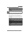
4.2.2
WR_74_75_PARAM
With this function the parameter string of a slave according to profile S-7.4 is being
written or the data transfer with a slave according to profile S-7.5 is started.
By a slave according to profile 7.5, data have to be registered into the buffer in the
same form, as they have to be sent by AS-i.
Since the string can be longer than the command interface, it is written into the
buffer in parts at first and then it is transferred to the slave.
n is the length of the part of the string which should be written into the buffer from
index i on.
Subject to reasonable modifications due to technical advances
16
Kohlhammerstraße 16, D-70771 Leinfelden-Echterdingen
Id.-No.: 102875 Issue date - 3.12.2007
EUCHNER GmbH + Co. KG
Tel. +49/711/7597-0, Fax +49/711/753316
AS-i 3.0 Command Interface
Commands of the Command Interface
If i ≡ 0, then the string is being transferred to the slave.
Request
byte
27
26
T
–
25
24
1
2
23
22
21
20
22
21
20
5A16
circuit
3
slave address
4
i
5
n
6
buffer byte i
…
…
n+5
buffer byte i+n-1
Response
byte
27
26
25
24
1
2
4.2.3
23
5A16
T
results
RD_74_75_PARAM
With this function the parameter string of a slave according to profile S-7.4 is being
read or the slave response according to profile S-7.5 is being read.
If it is about a slave according to profile 7.5, so have the data in the response buffer
the following meaning:
FFh 0016: Transfer is still active
FFh xx16: Transfer finished with error
The first byte in the buffer not equal FF16: slave response. The response is in the
same form registered in the buffer and transmitted over AS-i.
Since the string can be longer than the command interface, it is written into the
buffer. The content of the buffer can read in parts from index i.
The first byte of the buffer is the length of the read string.
If i ≡ 0, the string is being read from the slave, otherwise the function responses
out of the memory; the data can be read consistently.
Request
byte
27
26
1
2
25
24
23
22
21
20
5B16
T
–
circuit
3
slave address
4
i
Subject to reasonable modifications due to technical advances
Kohlhammerstraße 16, D-70771 Leinfelden-Echterdingen
Id.-No.: 102875 Issue date - 3.12.2007
EUCHNER GmbH + Co. KG
Tel. +49/711/7597-0, Fax +49/711/753316
17
AS-i 3.0 Command Interface
Commands of the Command Interface
Response
byte
2
7
2
6
2
5
24
1
2
22
21
20
5B16
T
result
3
4.2.4
23
buffer byte i
…
…
n+2
buffer byte i+n-1
RD_74_75_ID
With this function the ID string of a slave according to profile S-7.4 or the 16-bit
slave configuration according to profile 7.5 is being read. Since the string can be
longer than the command interface, it is written into the buffer. The content of the
buffer can read in parts from index i.
The first byte of the buffer is the length of the read string.
If i ≡ 0, the string is being read from the slave, otherwise the function responses
out of the memory, the data can be read consistently.
Request
byte
27
26
25
24
1
2
23
22
21
20
22
21
20
5C16
T
–
circuit
3
slave address
4
i
Response
byte
2
7
2
6
1
2
2
5
24
23
5C16
T
3
result
buffer byte i
…
…
n+2
buffer byte i+n-1
By a 7.5 slave is the request always 1. The response byte contains the cyclic 16bit slave configuration according to S-7.5 profile (analog/transparent bits are cancelled). If the response is 0816, that means that the cyclic 16-bit configuration could
not be detected.
Subject to reasonable modifications due to technical advances
18
Kohlhammerstraße 16, D-70771 Leinfelden-Echterdingen
Id.-No.: 102875 Issue date - 3.12.2007
EUCHNER GmbH + Co. KG
Tel. +49/711/7597-0, Fax +49/711/753316
AS-i 3.0 Command Interface
4.2.5
Commands of the Command Interface
RD_74_DIAG
With this function the diagnosis string of a slave according to profile S-7.4 is being
read. Since the string can be longer than the command interface, it is written into
the buffer. The content of the buffer can be read in parts from index i.
The first byte of the buffer indicates the length of the read string.
If i ≡ 0, the string is being read from the slave, otherwise the function responses
out of the memory, the data can be read consistently.
Request
byte
27
26
25
24
1
2
23
22
21
20
22
21
20
5D16
T
–
circuit
3
slave address
4
i
Response
byte
2
7
26
25
1
2
24
23
5D16
T
result
3
buffer byte i
…
…
n+2
buffer byte i+n-1
4.3
Acyclic commands
4.3.1
Overview of the commands
Values for command
Req
Len
Res
Len
see page
Command
Value
Meaning
page 19
WRITE_ACYC_TRANS
4E16
write acyclic transfer
≥7
2
page 21
READ_ACYC_TRANS
4F16
read acyclic transfer
5
≥2
4.3.2
WRITE_ACYCLIC_TRANS
This function starts various types of acyclic transfer (S-7.4, S-7.5 and Safety Monitor). The transfer is performed in the background. The result must be read using
READ_ACYC_TRANS. The function is intended to be a replacement for the functions (RD_74_75_PARAM, WR_74_75_PARAM, RD_74_75_ID, RD_74_DIAG
and "Safety at Work" monitor diagnostics), as it runs in the background and does
not stop the AS-i master during the transfer.
As the data to be transferred can be longer than the command interface, the data
is first written to a buffer in sections before the transfer is started.
Subject to reasonable modifications due to technical advances
Kohlhammerstraße 16, D-70771 Leinfelden-Echterdingen
Id.-No.: 102875 Issue date - 3.12.2007
EUCHNER GmbH + Co. KG
Tel. +49/711/7597-0, Fax +49/711/753316
19
AS-i 3.0 Command Interface
Commands of the Command Interface
n is the length of the sub-string that is to be written to the buffer starting from index
(i). When i = 0, the transfer is started.
Request
Byte
2
7
2
6
2
5
24
23
1
2
22
21
20
4E16
T
circuit
3
slave address
4
buffer index (i) high
5
buffer index (i) low
6
command1
7
number of (n)
8
data 0
…
...
n+7
data n-1
1. For a list of all supported commands <see table "Espoused commands", page
20>.
Espoused commands
see page
Command
Description
page 23
1
read string S-7.4 ID
page 23
2
read string S-7.4 diag
page 23
3
read string S-7.4 param string
page 23
4
write S-7.4 param string
page 24
5
transfer S-7.5
page 24
6
read S-7.5 cyclic 16-bit slave configuration
page 24
7
read safety monitor sorted by OSSD
page 26
8
read safety monitor unsorted (all devices) by OSSD
page 26
9
reserved / not defined
!!!
page 27
10
safety monitor diagnosis
!!!
page 27
11
shutdown-history, separate for each release circuit
12
safety monitor diagnosis, but the module allocation has been considered
13
safety monitor diagnosis, but the module allocation has been considered
!!!
page 27
!!!
page 27
!!!
page 28
14
diagnosis / shutdown-history, separate for each release circuit
!!!
page 30
15
safety status
!!!
The commands 10 ... 15 are available only with safety monitors (external and
integrated) in the version 2 and higher.
Subject to reasonable modifications due to technical advances
20
Kohlhammerstraße 16, D-70771 Leinfelden-Echterdingen
Id.-No.: 102875 Issue date - 3.12.2007
EUCHNER GmbH + Co. KG
Tel. +49/711/7597-0, Fax +49/711/753316
AS-i 3.0 Command Interface
Commands of the Command Interface
Response
Byte
4.3.3
2
7
2
6
2
5
24
23
1
4E16
2
return
22
21
20
READ_ACYCLIC_TRANS
With this call the response of
WRITE_ACYCLIC_TRANS) is read.
the
transfer
command
(started
with
Request
Byte
27
26
25
24
1
2
23
22
21
20
22
21
20
4F16
T
circuit
3
slave address
4
buffer index (i) high
5
buffer index (i) low
Response
Byte
2
7
26
25
1
2
23
4F16
T
response
3
data i
...
m
24
...
data i+(m-2)
1
1. command interface response length m
The response data have the same format, as by commands RD_74_75_PARAM,
RD_74_75_ID and „safety at work“-monitor diagnostics <see chapter 4.7.2 "Safety
at Work" Monitor diagnosis, page 64>.
4.3.3.1
Structure of the response buffer
As the string to be transferred can be longer than the command interface, the
string is first saved in a buffer that can be read in sections using the buffer index (i).
The first byte in the response buffer defines the current command. FF16 signifies
transfer still active, FE16 signifies transfer interrupted with errors. In the correct
case, the command from WRITE_ACYC_TRANS is given here.
The first sub-section of the string is read using i ≡ 0, the second with i = n-2, etc.
The two following bytes (high, low) define the length of the response buffer.
Subject to reasonable modifications due to technical advances
Kohlhammerstraße 16, D-70771 Leinfelden-Echterdingen
Id.-No.: 102875 Issue date - 3.12.2007
EUCHNER GmbH + Co. KG
Tel. +49/711/7597-0, Fax +49/711/753316
21
AS-i 3.0 Command Interface
Commands of the Command Interface
It is recommended to start reading the data always using index i ≡ 0. This message
also contains the header. The user data length is therefore reduced by 3 bytes.
Data with length i ≡ 0 can be read successfull only once. Each further read
command with length i ≡ 0 ist quit with an error. Therefore further read process (sections) must be carried out with i >0!
Response buffer
Byte
27
26
25
24
23
1
command1
2
length byt2e n (high)
3
length byte n (low)
4
data 0
...
...
n+3
data n-1
22
21
20
1. FFh signifies transfer still active, FEh signified transfer interrupted with errors. In the correct case the command from
WRITE_ACYC_TRANS is given here.
2. Transmit buffer length n
i=0
command
length byte high
length byte low
data 0
command
length byte high
length byte low
data 0
i=m-2
data n-1
data n-1
read section of the string
m - command interface response length
n - transmit buffer length
For further information <see chapter 5.4 Example for the readout of the safety
monitor with ACYC_TRANS, page 88>
Subject to reasonable modifications due to technical advances
22
Kohlhammerstraße 16, D-70771 Leinfelden-Echterdingen
Id.-No.: 102875 Issue date - 3.12.2007
EUCHNER GmbH + Co. KG
Tel. +49/711/7597-0, Fax +49/711/753316
AS-i 3.0 Command Interface
4.3.3.2
Commands of the Command Interface
Command 1: Read „S-7.4 ID String"
With this call the ID string of a slave according to profile S-7.4 can be read.
Response buffer
byte
4.3.3.3
27
26
25
24
23
1
ID string byte 0
2
ID string byte 1
...
...
n
ID string byte n-1
22
21
20
Command 2: Read „S-7.4 Diag String"
With this call the diag string of a slave according to profile S-7.4 can be read.
Response buffer
byte
4.3.3.4
2
7
2
6
2
5
24
23
1
diag string byte 0
2
diag string byte 1
...
...
n
diag string byte n-1
22
21
20
Command 3: Read „S-7.4 Param String"
With this call the param string of a slave according to profile S-7.4 can be read.
Response buffer
Byte
4.3.3.5
2
7
26
25
24
23
1
param string byte 0
2
param string byte 1
22
...
...
n
param string byte n-1
21
20
Command 4: Write „S-7.4 Param String“
With this call the param string of a slave according to profile S-7.4 can be written.
Request buffer
Byte
27
26
25
24
23
1
param string byte 0
2
param string byte 1
22
...
...
n
param string byte n-1
Subject to reasonable modifications due to technical advances
Kohlhammerstraße 16, D-70771 Leinfelden-Echterdingen
Id.-No.: 102875 Issue date - 3.12.2007
21
20
EUCHNER GmbH + Co. KG
Tel. +49/711/7597-0, Fax +49/711/753316
23
AS-i 3.0 Command Interface
4.3.3.6
Commands of the Command Interface
Command 5: „Transfer S-7.5“
With this call the transfer string of a slave according to profile S-7.5 can be trasferred. The request/response buffer contain the S-7.5 strings in the same form as
they are transferred via AS-i.
Request buffer
Byte
27
26
1
25
24
23
22
21
20
21
20
CTT2 command byte (1610 - 1910)
2
index
3
length
4
data 0
5
data 1
...
...
n
data n-4
Response buffer
Byte
4.3.3.7
2
7
26
25
24
23
22
1
CTT2 reponse byte (5010 - 5210, 9010 - 9210)
2
data 0
3
data 1
...
...
n
data n-2
Command 6: Read „Cyclical S-7.5 16-bit configuration“
With this call the cyclical S-7.5 16-bit configuration can be read, the analog/tranparent bits being deleted in the response.
The cyclical 16-bit configuration cannot be determined if the response is 0816.
Response buffer
4.3.3.8
Byte
27
1
0
26
25
24
0: no output
1: 1-byte output
2: 1-word output
3: 2-word output
4: 3-word output
5: 4-word output
23
22
21
20
0: no input
1: 1-byte input
2: 1-word input
3: 2-word input
4: 3-word input
5: 4-word input
0: data
are
valid
1: data
are not
valid
Command 7: Read „Safety Monitor sorted acc. to OSSD“
With this command the safety monitor is being read sorted acc. to the OSSD.
Response buffer
Byte
27
26
24
23
0
0016
1
monitor state
Subject to reasonable modifications due to technical advances
24
25
Kohlhammerstraße 16, D-70771 Leinfelden-Echterdingen
Id.-No.: 102875 Issue date - 3.12.2007
22
21
20
EUCHNER GmbH + Co. KG
Tel. +49/711/7597-0, Fax +49/711/753316
AS-i 3.0 Command Interface
Commands of the Command Interface
Response buffer
Byte
2
7
2
6
2
5
24
2
23
22
21
20
OSSD 1 state
3
OSSD 2 state
4
number of not green1 devices, OSSD 1
5
number of not green2 devices, OSSD 2
6
device index 32, OSSD 1
7
device colour 32, OSSD 1
8
device index 33, OSSD 1
…
…
133
device colour 95, OSSD 1
134
device index 32, OSSD 2
…
…
261
device colour 95, OSSD 2
1. The maximal value is 7, higher values are limited to 7.
2. The maximal value is 7, higher values are limited to 7.
Subject to reasonable modifications due to technical advances
Kohlhammerstraße 16, D-70771 Leinfelden-Echterdingen
Id.-No.: 102875 Issue date - 3.12.2007
EUCHNER GmbH + Co. KG
Tel. +49/711/7597-0, Fax +49/711/753316
25
AS-i 3.0 Command Interface
4.3.3.9
Commands of the Command Interface
Command 8: Read „Safety Monitor unsorted by OSSD“
With this command the safety monitor is being read unsorted by OSSD
Response buffer
Byte
27
26
25
24
0
23
22
21
20
0016
1
monitor state
2
OSSD 1 state
3
OSSD 2 state
4
number of not green1 devices, OSSD 1
5
—
6
device index 32
7
device colour 32
8
device index 33
…
…
133
device colour 95
134
device index 32
135
assignment of the device 32 to the OSSD
…
…
261
assignment of the device 95 to the OSSD
1. The maximal value is 7, higher values are limited to 7.
Following assignment is possible:
0016: Preprocessing
0116: OSSD 1
0216: OSSD 2
0316: OSSD 1+2
8016: Device doesn‘t exist
See <chapter 6 "Appendix: Code description", on page 94> for a description of
the codes used for monitor state, OSSD state, device colours and assignments to OSSDs and the "Safety-at-Work" monitor documentation.
4.3.3.10 Command 9: „reserved“
This command is reserved for future developments.
Subject to reasonable modifications due to technical advances
26
Kohlhammerstraße 16, D-70771 Leinfelden-Echterdingen
Id.-No.: 102875 Issue date - 3.12.2007
EUCHNER GmbH + Co. KG
Tel. +49/711/7597-0, Fax +49/711/753316
AS-i 3.0 Command Interface
4.3.3.11
Commands of the Command Interface
Commands 10 - 13: Safety unit diagnosis and shutdown-history
!!!
The commands 10 ... 15 are available only with safety monitors (external and
integrated) in the version 2 and higher.
In the case of a second generation safety monitor, the shutdown-history can be
read additionally to the safety unit diagnosis.
If an OSSD abandons the state green, the states of all devices are hold on at this
moment. Therefore it is possible to detect the cause for the turning-off läter.
If there has been no turning-off of the related OSSD since the start, all devices are
grey.
If the ACYC_TRANS slave address is "0", the internal monitor is activated, otherwise the external one.
Command
Description
10
safety monitor diagnosis
11
shutdown-history, separate for each release circuit
12
safety monitor diagnosis, but the module allocation has been
considered
13
shutdown-history, but the module allocation has been considered
Request buffer (only for commands 10 + 11)
Byte
2
7
26
1
25
24
23
22
21
20
21
20
OSSD: 0=OSSD 1; 1=OSSD 2
Response buffer
Byte
2
7
2
6
2
5
24
23
22
0
reserved 0016
1
monitor state1
2
OSSD 1 state2
3
OSSD 2 state
4
number of not green3 devices
5
—
6
device index 32
7
device4 colour 32
8
device index 33
9
device colour 33
...
132
Subject to reasonable modifications due to technical advances
Kohlhammerstraße 16, D-70771 Leinfelden-Echterdingen
device index 95
Id.-No.: 102875 Issue date - 3.12.2007
EUCHNER GmbH + Co. KG
Tel. +49/711/7597-0, Fax +49/711/753316
27
AS-i 3.0 Command Interface
Commands of the Command Interface
Response buffer
Byte
2
7
2
6
2
5
24
133
23
22
21
20
device colour 95
134
device index 32
135
assignment5 of the device 32 to the OSSD
...
260
device index 95
261
assignment of the device 95 to the OSSD
1. For code description see table "Monitor state", page 94
2. By means of device colours it is possible to form an opinion about the state of the OSSDs (see table "Colour coding", page 94)
3. The maximal value is 7, higher values are limited to 7
4. By means of device colours it is possible to form an opinion about the state of the OSSDs (see table "Colour coding", page 94)
5. For assignment of the devices to the OSSD see table "Allocation", page 95
4.3.3.12 Command 14: "Diagnosis / shutdown-history"
With this command the "diagnosis / shutdown-history" can be read separate for
each release circuit.
Request buffer
Byte
1
2
7
26
25
24
23
22
21
20
list selection (0=current diagnosis; >0=diagnosis by OSSD turning-off
(past events memory)
2
number of the OSSD (0=preprocessing)
3
Fdiagnosis format
(0=comlete diagnosis; 1=sorted according to the diagnosis index)
Response buffer
Byte
27
26
24
23
22
21
20
1
response type (0=device colour; >0=reserved)
2
monitor state; byte 1 (see table "Monitor state", page 29 for description)
3
OSSD type (0=internal OSSD; 1=peripheral OSSD)
4
OSSD info
- OSSD number, if internal OSSD (0=preprocessing, 1=OSSD 1,
2=OSSD 2);
- Slave address, if peripheral OSSD (address 0 – 63, bit 7 points at the
AS-i circuit that is allocated to the AS-i slave; 0=circuit 1, 1=circuit 2)
5
OSSD state (Bit 0-bit 3 colour of the OSSD; bit 4-bit 7 reserved)
6
colour device 0 (description see table "State and colour coding", page
29).
...
261
...
colour device 255
Subject to reasonable modifications due to technical advances
28
25
Kohlhammerstraße 16, D-70771 Leinfelden-Echterdingen
Id.-No.: 102875 Issue date - 3.12.2007
EUCHNER GmbH + Co. KG
Tel. +49/711/7597-0, Fax +49/711/753316
AS-i 3.0 Command Interface
Commands of the Command Interface
Monitor state
Bit [4 ... 0]
0 ... 31
reserved
Bit 5
configuration mode
0
monitor not in configuration mode
1
monitor in configuration mode
Bit 6
protected mode
0
monitor not in protected mode
1
monitor in protected mode
Bit 7
device error
0
no device error
1
fatal device error, RESET or device exchange required
State and colour coding
Bit [2 ... 0] State and/or colour coding
0
green permanent light
1
green flashing
2
yellow permanent light
3
yellow flashing
4
red permanent light
5
red flashing
6
grey and/or off
7
reserved
Bit [4 ... 3]
0 ... 3
reserved
Bit 5
modification
0
no device modification by "switch off"
1
device modification by "switch off"
Bit 6
existence
0
device exists
1
device doesn‘t exist
Bit 7
Usage
0
device is used in this OSSD
1
device is not used in this OSSD
Subject to reasonable modifications due to technical advances
Kohlhammerstraße 16, D-70771 Leinfelden-Echterdingen
Id.-No.: 102875 Issue date - 3.12.2007
EUCHNER GmbH + Co. KG
Tel. +49/711/7597-0, Fax +49/711/753316
29
AS-i 3.0 Command Interface
Commands of the Command Interface
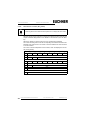
4.3.3.13 Command 15: "Safety Status"
With this command the status of safety monitors (external and integrated) in the
version 2 can be read.
Request buffer
Byte
2
7
2
6
2
5
24
1
23
22
21
20
22
21
20
reserved 0016
Response buffer
Byte
27
26
25
24
23
1
reserved 0016
2
OSSD 1 state1
3
OSSD 2 state2
...
...
n
OSSD n-1 state3
1. see table "Coding of status byte", page 30
2. see table "Coding of status byte", page 30
3. see table "Coding of status byte", page 30
Coding of status byte
Bit [0 ... 2]
state and/or colour
0
green permanent light
1
green flashing
2
yellow permanent light
3
yellow flashing
4
red permanent light
5
red flashing
6
grey and/or off
7
reserved
Bit [6]
state and/or colour
0
no device flashes yellow in this OSSD
1
at least one device flashes yellow in this OSSD
Bit [7]
state and/or colour
0
no device flashes red in this OSSD
1
at least one device flashes red in this OSSD
Subject to reasonable modifications due to technical advances
30
Kohlhammerstraße 16, D-70771 Leinfelden-Echterdingen
Id.-No.: 102875 Issue date - 3.12.2007
EUCHNER GmbH + Co. KG
Tel. +49/711/7597-0, Fax +49/711/753316
AS-i 3.0 Command Interface
Commands of the Command Interface
4.4
AS-i Diagnosis
4.4.1
Overview of the commands
Values for command
Req
Len
Res
Len
Get LDS, LAS, LPS, Flags
2
29
Get_Flags
2
5
5716
Get list of config. diff.
2
10
GET_LCS
6016
Get LCS
2
10
GET_LAS
4516
Get_LAS
2
10
page 36
GET_LDS
4616
Get_LDS
2
10
page 37
GET_LPF
3E16
Get_LPF
2
10
page 37
GET_LOS
6116
GET_LOS
2
10
page 38
SET_LOS
6216
SET_LOS
10
2
page 39
GET_TECA
6316
Get transm.err.counters
2
34
page 40
GET_TECB
6416
Get transm.err.counters
2
34
page 41
GET_TEC_X
6616
Get transm.err.counters
4
≥3
page 41
READ_FAULT_DETECTOR1 1016
Read Fault Detector
2
4
page 42
READ_DUPLICATE_ADDR2
Read List of Duplicate Addresses
2
10
see page
Command
Value
Meaning
page 31
GET_LISTS
3016
page 33
GET_FLAGS
4716
page 34
GET_DELTA
page 35
page 35
1116
1. The command READ_FAULT_DETECTOR is valid only for the use with masters which support this function. Please see the user manual of the
master for further information.
2. The command READ_DUPLICATE_ADDR is valid only for the use with masters which support this function. Please see the user manual of the
master for further information.
4.4.2
Get Lists and Flags (Get_LPS, Get_LAS, Get_LDS, Get_Flags)
(GET_LISTS)
With this call, the following entries of the AS-i Master can be read:
• The list of active AS-i slaves (LAS)
• The list of detected AS-i slaves (LDS)
• The list of projected AS-i slaves (LPS)
• The flags according to the AS-i slave specification
Request
byte
2
7
26
25
24
1
2
23
22
21
20
22
21
20
2A
1A
0A
3016
T
O
7
6
circuit
Response (if O ≡ 0)
byte
2
2
25
24
1
23
3016
2
T
3
7A
result
6A
Subject to reasonable modifications due to technical advances
Kohlhammerstraße 16, D-70771 Leinfelden-Echterdingen
5A
4A
3A
Id.-No.: 102875 Issue date - 3.12.2007
EUCHNER GmbH + Co. KG
Tel. +49/711/7597-0, Fax +49/711/753316
31
AS-i 3.0 Command Interface
Commands of the Command Interface
Response (if O ≡ 0)
byte
2
7
2
6
25
24
…
23
22
21
20
LAS
10
31B
30B
29B
28B
27B
26B
25B
24B
11
7A
6A
5A
4A
3A
2A
1A
0A
…
LDS
18
31B
30B
29B
28B
27B
26B
25B
24B
19
7A
6A
5A
4A
3A
2A
1A
0A
27B
26B
25B
24B
AAv
AAs
S0
Cok
AAe
OL
DX
22
21
20
4A
5A
6A
7A
…
LPS
26
31B
30B
29B
27
28B
–
28
OR
APF
29
NA
Pok
CA
–
Response (if O ≡ 1)
byte
2
7
26
25
24
1
3016
2
T
3
0A
result
1A
2A
3A
…
LAS
10
24B
25B
26B
27B
28B
29B
30B
31B
11
0A
1A
2A
3A
4A
5A
6A
7A
…
LDS
18
24B
25B
26B
27B
28B
29B
30B
31B
19
0A
1A
2A
3A
4A
5A
6A
7A
28B
29B
30B
31B
AAv
AAs
S0
Cok
AAe
OL
DX
…
26
LPS
24B
25B
26B
27
28
27B
–
OR
APF
NA
29
–
Pok
S0
AAs
AAv
CA
NA
APF
OR
Cok
AAe
OL
DX
Periphery_Ok
LDS.0
Auto_Address_Assign
Auto_Address_Available
Configuration_Active
Normal_Operation_Active
APF
Offline_Ready
Config_Ok
Auto_Address_Enable
Offline
Data_Exchange_Active
Subject to reasonable modifications due to technical advances
32
23
Kohlhammerstraße 16, D-70771 Leinfelden-Echterdingen
CA
Pok
Id.-No.: 102875 Issue date - 3.12.2007
EUCHNER GmbH + Co. KG
Tel. +49/711/7597-0, Fax +49/711/753316
AS-i 3.0 Command Interface
4.4.3
Commands of the Command Interface
Get Flags (GET_FLAGS)
With this call, the flags according to the AS-i slave specification can be read.
Request
byte
27
26
25
24
1
23
22
21
20
22
21
20
AAs
S0
Cok
AAe
OL
DX
4716
2
T
–
7
6
circuit
Response
byte
2
2
2
5
24
1
2
23
4716
T
response
3
4
Pok
OR
APF
5
NA
CA
AAv
–
Pok Periphery_OK
This flag is set when no AS-i slave is signaling a peripheral fault.
S0
LDS.0
This flag is set when an AS-i slave with address 0 exists.
AAs Auto_Address_Assign
This flag is being set when the automatic address programming is possible
(in other words, AUTO_ADDR_ENABLE = 1; no "incorrect" slave connected
to the AS-i).
AAv Auto_Address_Available
This flag is set when the automatic address programming can be executed,
exactly one AS-i slave is currently out of operation.
CA
Configuration_Active
The flag is set in configuration mode and reset in protected mode.
NA
Normal_Operation_Active
This flag is set when the AS-i master is in normal operation.
APF AS-i Power Fail
This flag is set when the voltage on the AS-i cable is too low.
OR Offline_Ready
The flag is set when the offline phase is active.
Cok Config_O
This flag is set when the desired (configured) and actual configuration
match.
AAe Auto_Address_Enable
This flag indicates whether the automatic address programming is enabled
(bit = 1) or disabled (bit = 0) by the user.
Subject to reasonable modifications due to technical advances
Kohlhammerstraße 16, D-70771 Leinfelden-Echterdingen
Id.-No.: 102875 Issue date - 3.12.2007
EUCHNER GmbH + Co. KG
Tel. +49/711/7597-0, Fax +49/711/753316
33
AS-i 3.0 Command Interface
4.4.4
Commands of the Command Interface
OL
Offline
This flag is set when the mode should be changed to OFFLINE or when this
mode has already been reached.
DX
Data_Exchange_Active
If the "Data_Exchange_Active" flag is set, the data exchange between AS-i
master and slaves is available in the data exchange phase. If this bit is not
set the data exchange is not available. The read ID telegrams are transmitted to the slave.
The bit is set if the AS-i master enters the offline phase.
Get Delta List (GET_DELTA)
The delta list contains the list of slave addresses with configuration errors.
Request
byte
27
26
25
24
1
2
23
22
21
20
22
21
20
3A
2A
1A
–
27B
26B
25B
24B
22
21
20
4A
5A
6A
7A
28B
29B
30B
31B
5716
T
0
7
26
circuit
Response (if O ≡ 0)
byte
2
25
24
1
23
5716
2
T
3
7A
result
6A
5A
4A
…
…
10
31B
30B
29B
byte
27
26
25
28B
Response (if O ≡ 1)
24
1
5716
2
T
3
0
result
1A
2A
3A
…
10
…
24B
25B
Subject to reasonable modifications due to technical advances
34
23
Kohlhammerstraße 16, D-70771 Leinfelden-Echterdingen
26B
27B
Id.-No.: 102875 Issue date - 3.12.2007
EUCHNER GmbH + Co. KG
Tel. +49/711/7597-0, Fax +49/711/753316
AS-i 3.0 Command Interface
4.4.5
Commands of the Command Interface
Get list of corrupted Slaves (GET_LCS and GET_LCS_R6 (6CH))
The call GET_LCS_R6 (6CH) differs to the call GET_LCS in the half long LCS list.
With the bit 25 is selected if the upper (=1) or lower (=0) part of the LCS is read.
Read first with 25 in order to create a local copy of the LCS. Reading with bit 25=1
transmits the upper part of the copy.
With the call GET_LCS, the List of Corrupted Slaves (LCS) can be read.
Request
byte
2
7
2
6
2
5
24
1
23
22
21
20
22
21
20
3A
2A
1A
0A
27B
26B
25B
24B
22
21
20
4A
5A
6A
7A
28B
29B
30B
31B
21
20
6016
2
T
O
byte
27
26
circuit
Response (if O ≡ 0)
25
24
1
6016
2
T
3
7A
result
6A
5A
4A
…
10
23
…
31B
30B
29B
28B
Response (if O ≡ 1)
byte
2
7
26
25
24
1
6016
2
T
3
0A
result
1A
2A
3A
…
10
4.4.6
23
…
24B
25B
26B
27B
Get list of activated Slaves (GET_LAS)
With this call, the list of activated slaves (LAS) can be read.
Request
byte
27
26
1
2
25
24
23
22
4516
T
O
Subject to reasonable modifications due to technical advances
Kohlhammerstraße 16, D-70771 Leinfelden-Echterdingen
circuit
Id.-No.: 102875 Issue date - 3.12.2007
EUCHNER GmbH + Co. KG
Tel. +49/711/7597-0, Fax +49/711/753316
35
AS-i 3.0 Command Interface
Commands of the Command Interface
Response (if O ≡ 0)
byte
2
7
2
6
2
5
24
1
22
21
20
3A
2A
1A
0A
27B
26B
25B
24B
22
21
20
4A
5A
6A
7A
28B
29B
30B
31B
22
21
20
22
21
20
3A
2A
1A
0A
27B
26B
25B
24B
22
21
20
4A
5A
6A
7A
28B
29B
30B
31B
4516
2
T
3
7A
result
6A
5A
4A
…
10
23
…
31B
30B
29B
28B
Response (if O ≡ 1)
byte
2
7
2
6
25
24
1
4516
2
T
3
0A
result
1A
2A
3A
…
10
4.4.7
23
…
24B
25B
26B
27B
Get list of detected AS-i Slaves (GET_LDS)
With this call, the list of detected AS-i slaves (LDS) can be read.
Request
byte
27
26
2
T
O
byte
27
26
25
24
1
23
4616
circuit
Response (if O ≡ 0)
25
24
1
2
T
3
7A
result
6A
5A
4A
…
10
23
4616
…
31B
30B
29B
28B
Response (if O ≡ 1)
byte
2
7
2
6
25
24
1
4616
2
T
3
0A
result
1A
2A
3A
…
10
…
24B
25B
Subject to reasonable modifications due to technical advances
36
23
Kohlhammerstraße 16, D-70771 Leinfelden-Echterdingen
26B
27B
Id.-No.: 102875 Issue date - 3.12.2007
EUCHNER GmbH + Co. KG
Tel. +49/711/7597-0, Fax +49/711/753316
AS-i 3.0 Command Interface
4.4.8
Commands of the Command Interface
Get list of peripheral faults (GET_LPF)
With this call, the list of peripheral faults (LPF) signaled by the AS-i slaves is read
out from the AS-i master. The LPF is updated cyclically by the AS-i master. If and
when an AS-i slave signals faults of the attached peripherals (for example broken
wire) can be found in the description of the AS-i slave.
Request
byte
2
7
2
6
2
5
24
1
23
22
21
20
22
21
20
3A
2A
1A
0A
27B
26B
25B
24B
22
21
20
4A
5A
6A
7A
28B
29B
30B
31B
3E16
2
T
O
byte
27
26
circuit
Response (if O ≡ 0)
25
24
1
3E16
2
T
3
7A
result
6A
5A
4A
…
10
23
…
31B
30B
29B
28B
Response (if O ≡ 1)
byte
2
7
2
6
25
24
1
3E16
2
T
3
0A
result
1A
2A
3A
…
10
4.4.9
23
…
24B
25B
26B
27B
Get list of offline Slaves (GET_LOS)
With this call, the list of slaves causing the offline phase when a configuration error
occurs in being read out (List of Offline Slaves, LOS).
The user can choose the reaction of the master when a configuration error occurs.
The master can be switched off line when an important slave causes a configuration error; less important slaves can send an error to the host, AS-i however will
not be switched offline.
Request
byte
27
26
1
2
25
24
23
22
21
20
6116
T
O
Subject to reasonable modifications due to technical advances
Kohlhammerstraße 16, D-70771 Leinfelden-Echterdingen
circuit
Id.-No.: 102875 Issue date - 3.12.2007
EUCHNER GmbH + Co. KG
Tel. +49/711/7597-0, Fax +49/711/753316
37
AS-i 3.0 Command Interface
Commands of the Command Interface
Response (if O ≡ 0)
byte
2
7
2
6
25
24
1
22
21
20
3A
2A
1A
0A
27B
26B
25B
24B
22
21
20
4A
5A
6A
7A
28B
29B
30B
31B
6116
2
T
3
7A
result
6A
5A
4A
…
10
23
…
31B
30B
29B
28B
Response (if O ≡ 1)
byte
2
7
2
6
25
24
1
6116
2
T
3
0A
result
1A
2A
3A
…
10
4.4.10
23
…
24B
25B
26B
27B
Set list of offline Slaves (SET_LOS and SET_LOS_R6 (6Dh))
The call SET_LOS_R6 (6D16) differs to the call GET_LOS in the half long LOS list.
With the bit 25 is selected if the upper (=1) or lower (=0) part of the LOS is written.
With this call, the list of slaves causing the offline phase when a configuration error
occurs in being defined (List of Offline Slaves, LOS).
The user can choose the reaction of the master when a configuration error occurs.
The master can be switched offline when an important slave causes a configuration error; less important slaves can send an error to the host, AS-i however will
not be switched offline.
Request (if O ≡ 0)
byte
27
26
2
T
O
3
7A
6A
25
24
1
23
22
21
20
3A
2A
1A
0A
27B
26B
25B
24B
22
21
20
4A
5A
6A
7A
28B
29B
30B
31B
6216
circuit
5A
4A
…
…
10
31B
30B
29B
byte
27
26
25
28B
Request (if O ≡ 1)
24
1
2
T
1
3
0A
1A
circuit
2A
3A
…
10
…
24B
25B
Subject to reasonable modifications due to technical advances
38
23
6216
Kohlhammerstraße 16, D-70771 Leinfelden-Echterdingen
26B
27B
Id.-No.: 102875 Issue date - 3.12.2007
EUCHNER GmbH + Co. KG
Tel. +49/711/7597-0, Fax +49/711/753316
AS-i 3.0 Command Interface
Commands of the Command Interface
Response
byte
2
7
2
6
2
5
24
1
2
4.4.11
23
22
21
20
6216
T
result
Get transm.err.counters (GET_TECA)
In order to get the real number of transcription errors, multiply the value with 2
With this call the error counters of all single slaves/A-slaves can be read (see
chapter: Advanced Diagnostics for AS-i Masters in the manual of your AS-i Master).
With every reading out of the counts, the error counters will be restarted.
The counts are being read out via the corresponding host interface and will be deleted with every read access. The counter´s value is limited to 254. 255 will cause
a counter overflow.
The counts could be independent of the counters, which are displayed in the display of the gateway.
Request
byte
27
26
25
24
1
2
23
22
21
20
22
21
20
6316
T
–
7
6
circuit
Response
byte
2
2
1
2
2
5
24
23
6316
T
result
3
APF
4
slave 1A
…
…
34
slave 31A
Subject to reasonable modifications due to technical advances
Kohlhammerstraße 16, D-70771 Leinfelden-Echterdingen
Id.-No.: 102875 Issue date - 3.12.2007
EUCHNER GmbH + Co. KG
Tel. +49/711/7597-0, Fax +49/711/753316
39
AS-i 3.0 Command Interface
4.4.12
Commands of the Command Interface
Get transm.err.counters (GET_TECB)
In order to get the real number of transcription errors, multiply the value with 2
With this call, the counts of the error counters for B-slaves are being read out (see
chapter: Advanced Diagnostics for AS-i Masters in the manual of your AS-i Master).
With every reading out of the counts, the error counters will be restarted.
The counts are being read out via the corresponding host interface and will be deleted with every read access. The counter´s value is limited to 254. 255 will cause
a counter overflow.
The counts could be independent of the counters, which are displayed in the display of the gateway.
Request
byte
7
2
2
T
–
byte
27
26
2
6
2
5
24
1
23
22
21
20
22
21
20
6416
circuit
Response
1
2
24
23
6416
T
result
3
APF
4
slave 1B
…
…
34
slave 31B
Subject to reasonable modifications due to technical advances
40
25
Kohlhammerstraße 16, D-70771 Leinfelden-Echterdingen
Id.-No.: 102875 Issue date - 3.12.2007
EUCHNER GmbH + Co. KG
Tel. +49/711/7597-0, Fax +49/711/753316
AS-i 3.0 Command Interface
4.4.13
Commands of the Command Interface
Get transm.err.counters (GET_TEC_X)
Beginning with a definite slave address, the counts of the n error counters are being read out with this call.
With every reading out the counts, the error counters will be restarted.
The counts are being read out via the corresponding host interface and will be deleted with every read access. The counter´s value is limited to 254. 255 will cause
a counter overflow.
The counts could be independent of the counters, which are displayed in the display of the gateway.
Request
byte
27
26
T
–
25
24
1
2
23
22
21
20
22
21
20
6616
circuit
3
1. slave address
4
number of counters
Response
byte
27
26
25
24
1
2
T
result
3
4.4.14
23
6616
counter 1
…
…
n
counter n - 2
Read fault detector (READ_FAULT_DETECTOR)
!!!
The command READ_FAULT_DETECTOR is valid only for the use with masters which support this function.
Please see the user manual of the master for further information.
With this call all informations of the AS-i detector are read out. In the first byte are
stored the values transferred in the moment, in the second all values since the last
deleting. By it is possible to recognize immediate, no more existing before messages also. The second byte is deleted by reading.
Request
byte
27
26
1
2
25
24
23
22
21
20
1016
T
–
Subject to reasonable modifications due to technical advances
Kohlhammerstraße 16, D-70771 Leinfelden-Echterdingen
circuit
Id.-No.: 102875 Issue date - 3.12.2007
EUCHNER GmbH + Co. KG
Tel. +49/711/7597-0, Fax +49/711/753316
41
AS-i 3.0 Command Interface
Commands of the Command Interface
Response
byte
2
7
2
6
2
5
24
1
23
22
21
20
1016
2
T
3
DA
ST
US
ES
result
24 V
reserved
4
DA
ST
US
ES
24 V
reserved
DA
duplicate address
ST
noise
US
over voltage
ES
earth fault
24 V failure of the redundant 24V
4.4.15
Read list of duplicate addresses (READ_DUPLICATE_ADDR)
!!!
The command READ_DUPLICATE_ADDR is valid only for the use with masters which support this function.
Please see the user manual of the master for further information.
With this call the list of slaves with duplicate addresses (the assignment of one address to two slaves) is read out.
Request
byte
7
26
2
T
O
byte
27
26
2
25
24
1
23
22
21
20
22
21
20
3A
2A
1A
0A
27B
26B
25B
24B
1116
circuit
Response (if O ≡ 0)
25
24
1
1116
2
T
3
7A
result
6A
5A
4A
…
10
…
31B
30B
Subject to reasonable modifications due to technical advances
42
23
Kohlhammerstraße 16, D-70771 Leinfelden-Echterdingen
29B
28B
Id.-No.: 102875 Issue date - 3.12.2007
EUCHNER GmbH + Co. KG
Tel. +49/711/7597-0, Fax +49/711/753316
AS-i 3.0 Command Interface
Commands of the Command Interface
Response (if O ≡ 1)
byte
2
7
2
6
25
24
1
22
21
20
4A
5A
6A
7A
28B
29B
30B
31B
1116
2
T
3
0A
result
1A
2A
3A
…
10
23
…
24B
25B
26B
27B
Further diagnosis functions for "Safety at Work" and for availability (resp. for
warnings) of integrated sensors are detailed explained in the chapter "Functional Profiles" (chapter 4.7).
4.5
Configuration of AS-i Master
4.5.1
Overview of the commands
Values for command
see page
Command
Value
Req
Len
Meaning
Res
Len
page 43
SET_OP_MODE
0C16
Set_Operation_Mode
3
2
page 44
STORE_CDI
0716
Store_Actual_Configuration
2
2
page 45
READ_CDI
2816
Read_Actual_Configuration
3
4
page 45
SET_PCD
2516
Set_Permanent_Config
5
2
page 45
GET_PCD
2616
Get_Permanent_Config
3
4
page 47
SET_LPS
2916
SET_LPS
11
2
page 48
GET_LPS
4416
Get_LPS
2
10
page 48
STORE_PI
0416
Store_Actual_Parameter
2
2
page 49
WRITE_P
0216
Write_Parameter
4
3
page 49
READ_PI
0316
Read_Parameter
3
3
page 50
SET_PP
4316
Set_Permanent_Parameter
4
2
page 50
GET_PP
0116
Get_Permanent_Parameter
3
3
page 51
SET_AAE
0B16
Set_Auto_Address_Enable
3
2
page 53
SLAVE_ADDR
0D16
Change_Slave_Address
4
2
page 52
WRITE_XID1
3F16
Write_Extended_ID-Code_1
3
2
4.5.2
Set operation mode (SET_OP_MODE: Set_Operation_Mode)
This call switches between configuration mode and protected mode. In protected
mode, only AS-i slaves entered in the LPS and whose expected and actual configurations match, are being activated.
In other words: The slaves are being activated if the I/O configuration and the ID
codes of the detected AS-i slaves are identical to the configured values.
Subject to reasonable modifications due to technical advances
Kohlhammerstraße 16, D-70771 Leinfelden-Echterdingen
Id.-No.: 102875 Issue date - 3.12.2007
EUCHNER GmbH + Co. KG
Tel. +49/711/7597-0, Fax +49/711/753316
43
AS-i 3.0 Command Interface
Commands of the Command Interface
In configuration mode, all detected AS-i slaves (except for AS-i slave "0") are activated. This also applies to AS-i slaves for which there are differences between
the expected and actual configuration.
The “OPERATION MODE” bit is stored permanently; in other words, it is retained
after a cold/warm restart.
When you change from configuration mode to protected mode, the AS-i master will
do a warm restart (change to the offline phase followed by a change to the online
mode).
If an AS-i Slave with address "0" is entered in the LDS, the AS-i Master cannot change from configuration mode to protected mode.
Request
byte
7
26
T
–
2
25
24
1
2
23
22
21
20
22
21
20
0C16
circuit
3
operation mode
Response
byte
27
26
25
24
1
2
23
0C16
T
result
Meaning of bit operation mode:
0 = protected mode
1 = configuration mode
4.5.3
Store actual configuration (STORE_CDI)
With this call, the (actual) configuration data (I/O configuration, ID code, extended
ID1 code and extended ID2 code) of all AS-i slaves are stored permanently in the
EEPROM as the (expected) configuration data. The list of activated AS-i slaves
(LAS) is adopted in the list of permanent AS-i slaves (LPS).
When this command is executed, the AS-i master changes to the offline phase and
then changes back to the normal mode (warm restart on the AS-i master).
This command can only be executed in the configuration mode.
Request
byte
27
26
T
–
1
2
24
23
22
21
20
0716
Subject to reasonable modifications due to technical advances
44
25
Kohlhammerstraße 16, D-70771 Leinfelden-Echterdingen
circuit
Id.-No.: 102875 Issue date - 3.12.2007
EUCHNER GmbH + Co. KG
Tel. +49/711/7597-0, Fax +49/711/753316
AS-i 3.0 Command Interface
Commands of the Command Interface
Response
byte
2
7
2
6
2
5
24
1
2
4.5.4
23
22
21
20
0716
T
result
Read actual configuration (READ_CDI)
With this call, the following configuration data of an addressed AS-i slave obtained
by the AS-i master on the AS-i are read.
• I/O configuration
• ID code
• Extended ID1 code
• Extended ID2 code
The configuration data are specified by the manufacturer of the AS-i slave.
Request
byte
27
26
25
24
1
2
23
22
21
20
21
20
2816
T
3
–
circuit
–
B
slave address
Response
byte
2
7
2
6
2
5
24
1
2
23
22
2816
T
result
3
xID2
xID1
4
ID
I0
Meaning of bit B:
B = 0 Single AS-i slave or A-slave
B = 1 B-slave
4.5.5
Set permanent configuration (SET_PCD)
This call sets the following configuration data for the addressed AS-i slave:
• I/O configuration
• ID code
• Extended ID1 code
• Extended ID2 code
The configuration data are stored permanently on the EEPROM of the AS-i Master
and are used as the expected configuration by the AS-i master in the protected
mode. The configuration data are specified by the manufacturer of the AS-i slave.
If the addressed AS-i slave does not support an extended ID code 1/2, the value
Fhex must be specified.
Subject to reasonable modifications due to technical advances
Kohlhammerstraße 16, D-70771 Leinfelden-Echterdingen
Id.-No.: 102875 Issue date - 3.12.2007
EUCHNER GmbH + Co. KG
Tel. +49/711/7597-0, Fax +49/711/753316
45
AS-i 3.0 Command Interface
Commands of the Command Interface
When this command is executed, the AS-i master changes to the offline phase and
then changes back to the normal mode (warm restart).
This command can only be executed in the configuration mode.
Request
byte
7
2
T
–
2
6
2
5
24
1
2
23
22
21
20
21
20
2516
3
circuit
–
B
slave address
4
xID2
xID1
5
ID
I0
Response
byte
27
26
25
24
1
2
23
22
2516
T
result
Meaning of bit B:
B = 0Single AS-i slave or A-slave
B = 1B-slave
4.5.6
Get extended permanent configuration (GET_PCD)
This call reads the following configuration data (configured data) of an addressed
AS-i slave stored on the EEPROM of the AS-i master:
• I/O configuration
• ID code
• Extended ID1 code
• Extended ID2 code
The configuration data are specified by the manufacturer of the slave.
Request
byte
27
26
25
24
1
2
23
22
21
20
21
20
2616
T
3
–
circuit
–
B
slave address
Response
byte
2
7
26
25
1
2
23
22
2616
T
result
3
xID2
xID1
4
ID
I0
Subject to reasonable modifications due to technical advances
46
24
Kohlhammerstraße 16, D-70771 Leinfelden-Echterdingen
Id.-No.: 102875 Issue date - 3.12.2007
EUCHNER GmbH + Co. KG
Tel. +49/711/7597-0, Fax +49/711/753316
AS-i 3.0 Command Interface
Commands of the Command Interface
Meaning of bit B:
B = 0 Single AS-i slave or A-slave
B = 1 B-slave
4.5.7
Set list of projected slaves (SET_LPS and SET_LPS_R6 (6Bh))
The command SET_LPS_R6 (6Bh) differs from the command SET-LPs in:
• no empty byte (3)
• half so long LPS list
With the bit 25 is selected if the upper (=1) or lower (=0) part of the LCS is read.
With this call, the list of configured AS-i slaves is transferred for permanent storage
in the EEPROM of the master.
When this command is executed, the AS-i master changes to the offline phase and
then changes back to the normal mode (warm restart).
This command can only be executed in the configuration mode.
Request (if O ≡ 0)
byte
7
26
T
0
2
25
24
1
2
22
21
20
3A
2A
1A
–
27B
26B
25B
24B
22
21
20
4A
5A
6A
7A
28B
29B
30B
31B
23
22
21
20
2916
circuit
3
4
23
0016
7A
6A
5A
4A
…
…
11
31B
30B
29B
byte
27
26
25
28B
Request (if O ≡ 1)
24
1
2
T
1
circuit
3
4
23
2916
0016
–
1A
2A
3A
…
…
11
24B
25B
26B
byte
27
26
25
27B
Response
1
2
24
2916
T
Subject to reasonable modifications due to technical advances
Kohlhammerstraße 16, D-70771 Leinfelden-Echterdingen
result
Id.-No.: 102875 Issue date - 3.12.2007
EUCHNER GmbH + Co. KG
Tel. +49/711/7597-0, Fax +49/711/753316
47
AS-i 3.0 Command Interface
4.5.8
Commands of the Command Interface
Get list of projected slaves (GET_LPS)
With this call, the list of projected AS-i slaves (LPS) is read out of the AS-i Master.
Request
byte
27
26
25
24
1
2
23
22
21
20
22
21
20
3A
2A
1A
0A
27B
26B
25B
24B
22
21
20
4A
5A
6A
7A
28B
29B
30B
31B
4416
T
O
7
6
circuit
Response (if O ≡ 0)
byte
2
2
25
24
1
23
4416
2
T
3
7A
result
6A
5A
4A
…
…
10
31B
30B
29B
byte
27
26
25
28B
Response (if O ≡ 1)
24
1
4416
2
T
3
0A
result
1A
2A
3A
…
10
4.5.9
23
…
24B
25B
26B
27B
Store actual parameters (STORE_PI)
With this call, the configured parameters stored on the EEPROM are overwritten
with the current, permanently stored (actual) parameters; in other words, the current parameters of all AS-i slaves are stored.
Request
byte
7
26
2
T
–
byte
27
26
2
25
24
1
23
22
21
20
22
21
20
0416
circuit
Response
1
2
24
23
0416
T
Subject to reasonable modifications due to technical advances
48
25
Kohlhammerstraße 16, D-70771 Leinfelden-Echterdingen
result
Id.-No.: 102875 Issue date - 3.12.2007
EUCHNER GmbH + Co. KG
Tel. +49/711/7597-0, Fax +49/711/753316
AS-i 3.0 Command Interface
4.5.10
Commands of the Command Interface
Write parameter (WRITE_P)
The AS-i slave parameter value transferred with the command is passed on to the
addressed AS-i slave.
The parameter is stored in the AS-i Master only temporarily and is not stored as a
configured parameter in the EEPROM!
The AS-i slave transfers its current parameter value in the response (parameter
echo). This can deviate from the value that has just been written according to the
AS-i master specification.
Request
byte
7
2
T
–
2
6
2
5
24
1
2
23
22
21
20
0216
3
circuit
–
B
4
slave address
–
parameter
Response
byte
27
26
25
24
1
2
23
22
21
20
0216
T
result
3
–
slave response
Meaning of bit B:
B = 0 Single AS-i slave or A-slave
B = 1 B-slave
4.5.11
Read parameter (READ_PI: Read_Parameter)
This call returns the current parameter value (actual parameter) of an AS-i slave
sent by the AS-i Master. This value must not be confused with the parameter echo
that is supplied by the AS-i slave as a response to the write_p job.
This command can not be used for a directly reading of an AS-i parameter out of
an AS-i slave.
Request
byte
27
26
25
24
1
2
23
22
21
20
21
20
0316
T
3
–
circuit
–
B
slave address
Response
byte
2
7
26
25
1
2
24
23
22
0316
T
3
Subject to reasonable modifications due to technical advances
Kohlhammerstraße 16, D-70771 Leinfelden-Echterdingen
result
–
PI
Id.-No.: 102875 Issue date - 3.12.2007
EUCHNER GmbH + Co. KG
Tel. +49/711/7597-0, Fax +49/711/753316
49
AS-i 3.0 Command Interface
Commands of the Command Interface
Meaning of bit B:
B = 0 Single AS-i slave or A-slave
B = 1 B-slave
4.5.12
Set permanent parameter (SET_PP)
With this call, a parameter value for the specified AS-i slave is configured. The value is stored permanently in the EEPROM of the gateway.
The configured parameter value is transferred only when the AS-i slave is activated after turning on the power supply on the AS-i Master.
Request
byte
27
26
25
24
1
2
23
22
21
20
21
20
4316
T
3
–
circuit
–
B
4
slave address
–
PP
Response
byte
2
7
26
25
24
1
2
4.5.13
23
22
4316
T
result
Get permanent parameter (GET_PP)
With this call, a slave-specific parameter value stored on the EEPROM of the AS-i
Master is read.
Request
byte
7
26
T
–
2
25
24
1
2
23
22
21
20
21
20
0116
3
circuit
–
B
slave address
Response
byte
27
26
25
24
1
2
23
22
0116
T
3
result
–
PP
Meaning of bit B:
B = 0 Single AS-i slave or A-slave
B = 1 B-slave
Subject to reasonable modifications due to technical advances
50
Kohlhammerstraße 16, D-70771 Leinfelden-Echterdingen
Id.-No.: 102875 Issue date - 3.12.2007
EUCHNER GmbH + Co. KG
Tel. +49/711/7597-0, Fax +49/711/753316
AS-i 3.0 Command Interface
4.5.14
Commands of the Command Interface
Set auto address enable (SET_AAE)
This call can enable or disable the "automatic address programming" function.
The AUTO_ADDR_ENABLE bit is stored permanently; in other words, it is retained after a warm/hot restart on the AS-i master.
Request
byte
27
26
T
–
25
24
1
2
23
22
21
20
22
21
20
0B16
circuit
3
Auto_Address_Enable
Response
byte
27
26
25
24
1
2
4.5.15
23
0B16
T
result
Change slave address (SLAVE_ADDR)
With this call, the AS-i address of an AS-i slave can be modified.
This call is mainly used to add a new AS-i slave with the default address "0" to the
AS-Interface. In this case, the address is changed from "AS-i slave address
old" = 0 to "AS-i slave address new”.
This change can only be made when the following conditions are fulfilled:
1. An AS-i slave with “AS-ii slave address old” exists.
2. If the old AS-i slave address is not equal to 0, an AS-i slave with address "0"
cannot be connected at the same time.
3. The "AS-i slave address new" must have a valid value.
4. An AS-i slave with "AS-i slave address new" must not exist.
When the AS-i slave address is changed, the AS-i slave is not reset, in other
words, the output data of the AS-i slave are retained until new data are
received at the new address.
Request
byte
7
26
T
–
2
25
1
2
24
23
22
21
20
0D16
circuit
3
–
B
source address
4
–
B
target address
Subject to reasonable modifications due to technical advances
Kohlhammerstraße 16, D-70771 Leinfelden-Echterdingen
Id.-No.: 102875 Issue date - 3.12.2007
EUCHNER GmbH + Co. KG
Tel. +49/711/7597-0, Fax +49/711/753316
51
AS-i 3.0 Command Interface
Commands of the Command Interface
Response
byte
2
7
2
6
2
5
24
1
2
23
22
21
20
0D16
T
result
Meaning of bit B:
B = 0 Single AS-i slave or A-slave
B = 1 B-slave
4.5.16
Write AS-i slave extended ID1 (WRITE_XID1)
With this call, the extended ID1 code of an AS-i slave with address "0" can be written directly via the AS-i cable. The call is intended for diagnostic purposes and is
not required in the normal master mode.
The AS-i master passes the extended ID1 code on to the AS-i slave without any
plausibility check.
Request
byte
27
26
25
24
1
2
23
22
21
20
21
20
3F16
T
–
3
circuit
–
xID1
Response
Byte
2
7
2
6
1
2
24
23
22
3F16
T
Subject to reasonable modifications due to technical advances
52
2
5
Kohlhammerstraße 16, D-70771 Leinfelden-Echterdingen
result
Id.-No.: 102875 Issue date - 3.12.2007
EUCHNER GmbH + Co. KG
Tel. +49/711/7597-0, Fax +49/711/753316
AS-i 3.0 Command Interface
Commands of the Command Interface
4.6
Other commands
4.6.1
Overview of the commands
Values for command
see page
!
!
!
Command
Value
Req
Len
Meaning
Res
Len
page 53
IDLE
0016
No request
2
2
page 54
READ_IDI
4116
Read IDI
2
36
page 54
WRITE_ODI
4216
Write ODI
34
2
page 55
READ_ODI
5616
Read ODI
2
34
page 55
SET_OFFLINE
0A16
Set_Off-Line_Mode
3
2
page 56
SET_DATA_EX
4816
Set_Data_Exchange_Active
3
2
page 56
REWRITE_DPRAM1
7816
Rewrite DPRAM
3
3
page 56
BUTTONS
7516
Disable Pushbuttons
3
2
page 57
FP_PARAM
7D16
„Functional Profile“ Param.
≥3
≥2
page 58
FP_DATA
7E16
„Functional Profile“ Data
≥3
≥2
page 58
EXT_DIAG2
7116
ExtDiag generation
6
2
page 59
RD_EXT_DIAG3
7B16
Read ExtDiag Settings
2
7
page 60
INVERTER
Configure Inverter Slaves
12
4
page 60
MB_OP_CTRL_WR_FLAGS 8516
Write Flags
≥5
2
page 61
MB_OP_CTRL_RD_FLAGS
8616
Read Flags
4
≥3
page 61
RD_MFK_PARAM
5916
Read SEW MFK21 Parameter
6
≥3
7C16
1. The command REWRITE_DPRAM is valid only for the use with AS-i 3.0 Module OEM Master
2. The command EXT_DIAG is valid only for the use with AS-i 3.0 PROFIBUS Gateways
3. The command RD_EXT_DIAG is valid only for the use with AS-i 3.0 PROFIBUS Gateways
4.6.2
IDLE
When the value of "command" is zero, no request will be fulfilled.
Request
byte
27
26
T
–
7
26
25
24
1
2
23
22
21
20
22
21
20
0016
circuit
Response
byte
2
1
2
25
24
23
0016
T
Subject to reasonable modifications due to technical advances
Kohlhammerstraße 16, D-70771 Leinfelden-Echterdingen
result
Id.-No.: 102875 Issue date - 3.12.2007
EUCHNER GmbH + Co. KG
Tel. +49/711/7597-0, Fax +49/711/753316
53
AS-i 3.0 Command Interface
4.6.3
Commands of the Command Interface
Read input data image (READ_IDI)
With this call, the input data values of all AS-i slaves are read out of the AS-i Master in addition to the cyclic data exchange. Though the command READ_IDI transmits all execution control flags (byte 3 and byte 4).
Request
byte
27
26
25
24
1
23
22
21
20
22
21
20
AAs
s0
Cok
4116
2
T
–
7
26
circuit
Response
byte
2
25
24
1
4116
2
T
result
3
–
4
OR
APF
NA
5
–
6
slave 2A
AAv
slave 1A
slave 3A
…
36
4.6.4
Pok
CA
…
Pok
S0
AAs
AAv
CA
NA
APF
OR
Cok
23
slave 30B
slave 31B
Periphery_Ok
LDS.0
Auto_Address_Assign
Auto_Address_Available
Configuration_Active
Normal_Operation_Active
APF
Offline_Ready
Config_Ok
Write output data image (WRITE_ODI)
With this call the output data values of all AS-i slaves are written in addition to the
cyclic data exchange.
Request
byte
7
26
T
–
2
25
1
2
22
21
20
circuit
–
4
slave 2A
…
slave 1A
slave 3A
…
slave 30B
Subject to reasonable modifications due to technical advances
54
23
4216
3
34
24
Kohlhammerstraße 16, D-70771 Leinfelden-Echterdingen
slave 31B
Id.-No.: 102875 Issue date - 3.12.2007
EUCHNER GmbH + Co. KG
Tel. +49/711/7597-0, Fax +49/711/753316
AS-i 3.0 Command Interface
Commands of the Command Interface
Response
byte
2
7
2
6
2
5
24
1
2
4.6.5
23
22
21
20
4216
T
result
Read output data image (READ_ODI)
With this call, the output data values of all AS-i slaves is being read out of the ASi Master.
Request
byte
27
26
25
24
1
2
23
22
21
20
22
21
20
5616
T
–
7
26
circuit
Response
byte
2
25
1
2
23
5616
T
result
3
–
slave 1A
slave 2A
slave 3A
…
34
4.6.6
24
…
slave 30B
slave 31B
Set offline mode (SET_OFFLINE)
This call switches between online and offline mode.
The online mode is the normal operating state for the AS-i master. The following
jobs are processed cyclically:
• During the data exchange phase, the fields of the output data are transferred to
the slave outputs for all AS-i slaves in the LAS. The addressed AS-i slaves submit the values of the slave inputs to the master when the transfer was free of
errors.
• This is followed by the inclusion phase in which existing AS-i slaves are
searched and newly added AS-i slaves are entered in the LDS or LAS.
• In the management phase, jobs by the user such as writing parameters are executed.
In the offline mode, the AS-i Master processes jobs by the user only. (Jobs that
involve the immediate addressing of an AS-i slave are rejected with an error).
There is no cyclic data exchange with the AS-i slaves.
When offline, the AS-i circuit is in a safe state.
Subject to reasonable modifications due to technical advances
Kohlhammerstraße 16, D-70771 Leinfelden-Echterdingen
Id.-No.: 102875 Issue date - 3.12.2007
EUCHNER GmbH + Co. KG
Tel. +49/711/7597-0, Fax +49/711/753316
55
AS-i 3.0 Command Interface
Commands of the Command Interface
The OFFLINE = TRUE bit is not permanently stored; in other words, following a
cold/warm restart, the AS-i Master is once again in the online mode.
Request
byte
7
2
T
–
2
6
2
5
24
1
2
23
22
21
20
22
21
20
0A16
circuit
3
Off-Line
Response
byte
2
7
2
6
2
5
24
1
2
23
0A16
T
result
The master changes to the offline phase, if there is a 1 written in byte 3.
The master will change to online mode if there is a 0 written in byte 3.
4.6.7
Release data exchange (SET_DATA_EX)
Request
byte
7
2
T
–
2
6
2
5
24
1
2
23
22
21
20
22
21
20
21
20
4816
circuit
3
Data_Exchange_Active
Response
byte
27
26
25
24
1
2
4.6.8
23
4816
T
result
Rewrite DPRAM (REWRITE_DPRAM)
!!!
The command REWRITE_DPRAM is valid only for the use with
AS-i 3.0 Module OEM Master.
This command is used for the rewriting of the DPRAM.
Request
byte
27
26
1
2
24
23
22
7816
T
–
Subject to reasonable modifications due to technical advances
56
25
Kohlhammerstraße 16, D-70771 Leinfelden-Echterdingen
circuit
Id.-No.: 102875 Issue date - 3.12.2007
EUCHNER GmbH + Co. KG
Tel. +49/711/7597-0, Fax +49/711/753316
AS-i 3.0 Command Interface
Commands of the Command Interface
Response
byte
2
7
2
6
2
5
24
1
22
21
20
22
21
20
22
21
20
7816
2
4.6.9
23
T
result
BUTTONS
With this call, the use of the buttons can be enabled/disabled.
Request
byte
7
2
T
–
2
6
2
5
24
1
2
23
7516
circuit
3
Buttons disabled
Response
byte
27
26
25
24
1
2
4.6.10
23
7516
T
result
FP_PARAM
This command is used for parametrization of "functional profiles".
The content of the request and response bytes depends on the called function
(see chapter 4.7 Functional Profiles, page 62).
Request
byte
27
26
25
24
1
2
23
22
21
20
22
21
20
7D16
T
–
circuit
3
function
4
request byte 1
…
…
n
request byte n-3
Response
byte
2
7
2
1
2
6
2
5
24
23
7D16
T
3
result
response byte 1
…
…
n
response byte n-2
Subject to reasonable modifications due to technical advances
Kohlhammerstraße 16, D-70771 Leinfelden-Echterdingen
Id.-No.: 102875 Issue date - 3.12.2007
EUCHNER GmbH + Co. KG
Tel. +49/711/7597-0, Fax +49/711/753316
57
AS-i 3.0 Command Interface
4.6.11
Commands of the Command Interface
FP_DATA
This command is used for the data exchange with "functional profiles".
The content of the request and response bytes depends on the called function
(see chapter 4.7 Functional Profiles, page 62).
Request
byte
27
26
T
–
25
24
1
2
23
22
21
20
22
21
20
7E16
circuit
3
function
4
request byte 1
…
…
n
request byte n-3
Response
byte
27
26
25
24
1
2
T
result
3
4.6.12
23
7E16
reponse byte 1
…
…
n
response byte n-2
EXT_DIAG
!!!
The command EXT_DIAG is valid only for the use with AS-i 3.0 PROFIBUS
Gateways
With this call, the conditions when to set the ExtDiag bit can be selected.
Request
byte
7
26
T
–
2
1
2
24
23
22
21
20
7116
circuit
3
CF
4
APF
5
PF
6
CS
Subject to reasonable modifications due to technical advances
58
25
Kohlhammerstraße 16, D-70771 Leinfelden-Echterdingen
Id.-No.: 102875 Issue date - 3.12.2007
EUCHNER GmbH + Co. KG
Tel. +49/711/7597-0, Fax +49/711/753316
AS-i 3.0 Command Interface
Commands of the Command Interface
Response
byte
2
7
2
6
2
5
24
1
4.6.13
22
21
20
7116
2
CF
APF
PF
CS
23
T
result
ExtDiag is set, if ConfigError ≡ 1
ExtDiag is set, if APF ≡ 1
ExtDiag is set, if PeripheryFault ≡ 1
ExtDiag is set, if LCS is not empty
RD_EXT_DIAG
!!!
The command RD_EXT_DIAG is valid only for the use with
AS-i 3.0 PROFIBUS Gateways
With this call, the conditions when the ExtDiag bit is set can be read.
Request
byte
27
26
25
24
1
23
22
21
20
22
21
20
7B16
2
T
–
7
26
circuit
Response
byte
2
1
2
25
24
23
7516
T
result
3
CF
4
APF
5
PF
6
CS
7
FD
CF
APF
PF
CS
FD
ExtDiag is set by ConfigError ≡ 1
ExtDiag is set by APF ≡ 1
ExtDiag is set by PeripheryFault ≡ 1
ExtDiag is set, if LCS is not empty
Diagnosis will be updated only if this is dictated by the PROFIBUS norm.
Diagnosis date are not up to date when in doubt.
Subject to reasonable modifications due to technical advances
Kohlhammerstraße 16, D-70771 Leinfelden-Echterdingen
Id.-No.: 102875 Issue date - 3.12.2007
EUCHNER GmbH + Co. KG
Tel. +49/711/7597-0, Fax +49/711/753316
59
AS-i 3.0 Command Interface
4.6.14
Commands of the Command Interface
Inverter
With this call, an AS-i slave for frequency inverters is switched from cyclical mode
to the transmission mode of four 16-bit values, in order to operate again with the
selected AS-i destination parameter.
Request
byte
27
26
25
24
1
23
22
21
20
22
21
20
7C16
2
T
–
circuit
3
slave address
4
destination parameter
5
value 1, high byte
6
value 1, low byte
7
value 2, high byte
8
value 2, low byte
9
value 3, high byte
10
value 3, low byte
11
value 4, high byte
12
value 4, low byte
Response
byte
2
7
26
25
24
1
7C16
2
4.6.15
23
T
result
Write Flag
Use this command to write the flag of a control program.
The control program of devices with control functions takes on data from the PB
interface.
Request
Byte
27
26
T
–
1
2
24
23
22
21
20
8516
circuit
3
introductory address
4
number n
5
number 1
...
...
n
number n
Subject to reasonable modifications due to technical advances
60
25
Kohlhammerstraße 16, D-70771 Leinfelden-Echterdingen
Id.-No.: 102875 Issue date - 3.12.2007
EUCHNER GmbH + Co. KG
Tel. +49/711/7597-0, Fax +49/711/753316
AS-i 3.0 Command Interface
Commands of the Command Interface
Response
Byte
2
7
2
6
2
5
24
1
22
21
20
8516
2
4.6.16
23
T
result
Read Flag
Use this command to read out the flags of a control program.
The control program of devices with control functions takes on data from the superior fieldbus interface.
Request
Byte
27
26
25
24
1
2
23
22
21
20
22
21
20
8616
T
–
circuit
3
introductory address
4
number n
Response
Byte
2
7
26
25
24
1
2
23
8616
T
result
3
data 1
...
n
4.6.17
data n
READ_MFK_PARAM
Use this command to read multiple commands of a SEW MFK21 slave.
Request
Byte
27
26
25
24
1
2
23
22
21
20
22
21
20
5916
T
–
circuit
3
slave
4
index high
5
index low
6
number (n)
Response
Byte
2
7
2
1
2
6
2
5
24
23
5916
T
3
Subject to reasonable modifications due to technical advances
Kohlhammerstraße 16, D-70771 Leinfelden-Echterdingen
result
prm byte (index)
Id.-No.: 102875 Issue date - 3.12.2007
EUCHNER GmbH + Co. KG
Tel. +49/711/7597-0, Fax +49/711/753316
61
AS-i 3.0 Command Interface
Commands of the Command Interface
Response
Byte
2
7
2
6
2
5
24
23
4
prm byte (index+1)
n+2
prm byte (index+n-1)
4.7
Functional Profiles
4.7.1
"Safety at Work" List 1
22
21
20
This function has been implemented only for reasons of the downwards compatibility.
By AS-i 3.0 Masters, the state of the "safety input slaves" is specified on the
image of the input data (0000 released).
4.7.1.1
Slave list with EcFlags
(Function: 0016)
List of "safety-directed input slaves" ("AS-i Safety at Work"), whose safety function
is released.
Safety-directed input slaves have the profile S-7.B or S-0.B (IO = 0 or 7, ID = B,
see chapter 4.5.4 Read actual configuration (READ_CDI), page 45: Read Actual
Configuration).
The "Safety at Work" list 1 is a bit list which contains a bit for each possible slave
address (1 - 31). This list is written in the bytes 5 until 8 in the response of the command of the command interface. Additionally, the reponse contains the ec-flags of
the AS-i master in the bytes 3 and 4 (see chapter 4.4.3 Get Flags (GET_FLAGS),
page 33: "Get Flags").
The bits of the "Safety at Work" list 1 are set if the safety function of the slave is
activated (e.g. emergency button pressed). The bit is only set at security slaves
when both contacts are released, otherwise the bits have the value 0. "Normal"
(non-security) slaves also have the value 0.
Since the safety monitor is also being activated when a safety slave is missing or
if the AS-i circuit is shut off (offline active), the ec-flags will also be transmitted. It
is sufficient however to monitor the group error message Cok (configuration error).
As long as no configuration error, the list of the "safety-directed input slaves" can
be used.
Configured safety slaves which are not available, and available slaves sending a
wrong coder order, will not be entered in this list.
Subject to reasonable modifications due to technical advances
62
Kohlhammerstraße 16, D-70771 Leinfelden-Echterdingen
Id.-No.: 102875 Issue date - 3.12.2007
EUCHNER GmbH + Co. KG
Tel. +49/711/7597-0, Fax +49/711/753316
AS-i 3.0 Command Interface
Commands of the Command Interface
With the bit "O", the sequence of the bits within the "Safety at Work" list 1 can be
chosen.
Request
byte
2
7
2
6
2
5
24
1
23
22
21
20
22
21
20
AAs
S0
Cok
7E16
2
T
O
circuit
3
0016
Response (if O ≡ 0)
byte
27
26
25
24
1
23
7E16
2
T
result
3
–
4
OR
APF
NA
Pok
CA
AAv
5
7
6
5
4
3
2
1
-
6
15
14
13
12
11
10
9
8
7
23
22
21
20
19
18
17
16
8
31
30
29
28
27
26
25
25
7
26
22
21
20
AAv
AAs
S0
Cok
4
5
6
7
28
29
30
31
Response (if O ≡ 1)
byte
2
25
24
1
2
7E16
T
result
3
–
4
OR
APF
NA
CA
5
-
1
2
3
…
8
Cok
S0
AAs
AAv
CA
NA
APF
OR
Pok
23
Pok
…
24
25
26
27
Config_Ok
LDS.0
Auto_Address_Assign
Auto_Address_Available
Configuration_Active
Normal_Operation_Active
APF
Offline_Ready
Periphery_Ok
Example for O ≡ 0:
Configuration OK,
periphery OK (no peripheral fault,
2 safety slaves with released safety function,
AS-i addresses 4 and 10
Subject to reasonable modifications due to technical advances
Kohlhammerstraße 16, D-70771 Leinfelden-Echterdingen
Id.-No.: 102875 Issue date - 3.12.2007
EUCHNER GmbH + Co. KG
Tel. +49/711/7597-0, Fax +49/711/753316
63
AS-i 3.0 Command Interface
Commands of the Command Interface
1 safety slave with unreleased safety function,
AS-inferface address 5.
Reponse: 7E 00 01 25 10 04 00 00
4.7.1.2
Slave list without EcFlags
(Function: 0D16)
There is a function 0D16 in addition to the function 0016 . The function 0D16 has no
EcFlags in the response. The response falls short for 2 bytes.
Request
Byte
27
26
25
24
1
2
23
22
21
20
22
21
20
7E16
T
O
circuit
3
0Dh
Response (by O ≡ 0)
Byte
2
7
26
25
24
1
23
7E16
2
T
3
7
6
5
4
response
3
2
1
–
4
15
14
13
12
11
10
9
8
5
23
22
21
20
19
18
17
16
6
31
30
29
28
27
26
25
24
7
26
22
21
20
Response (by O ≡ 1)
Byte
2
25
24
1
4.7.2
23
7E16
2
T
3
–
1
2
3
response
4
5
6
7
4
8
9
10
11
12
13
14
15
5
16
17
18
19
20
21
22
23
6
24
25
26
27
28
29
30
31
"Safety at Work" Monitor diagnosis
Function: 0216
Since the "Safety at Work" monitor can generate more than 32 Byte diagnosis data, these must be read with several command interface calls. The byte 5 declares
the start index in the field of the diagnosis data.
If the start index is 0, new data is fetched from the monitor. Otherwise, the function
will respond out of the memory; the data can be read consistently.
Subject to reasonable modifications due to technical advances
64
Kohlhammerstraße 16, D-70771 Leinfelden-Echterdingen
Id.-No.: 102875 Issue date - 3.12.2007
EUCHNER GmbH + Co. KG
Tel. +49/711/7597-0, Fax +49/711/753316
AS-i 3.0 Command Interface
4.7.3
Commands of the Command Interface
Setting of the AS-i diagnosis
The function unsorted diagnosis is available only with monitors in the version 2.0 and higher.
The function sorted diagnosis is available with all monitors.
The setting of the AS-i diagnosis takes place in the window "Information about
monitor and bus" of the configuration software asimon for the AS-i safety monitor.
• Call up the menu Edit/Information about monitor and bus
Fig. 1. Calling of Information about monitor and bus
Subject to reasonable modifications due to technical advances
Kohlhammerstraße 16, D-70771 Leinfelden-Echterdingen
Id.-No.: 102875 Issue date - 3.12.2007
EUCHNER GmbH + Co. KG
Tel. +49/711/7597-0, Fax +49/711/753316
65
AS-i 3.0 Command Interface
Commands of the Command Interface
• Set the function range in the window Information about monitor and bus
Fig. 2.
Setting of function range
• Select in the window Information about monitor and bus the tab Diagnosis/Service
• Select within the range Data selection sorted (sorted by OSSD) or unsorted (all
devices)
Fig. 3.
Data selection (sorted/unsorted)
Subject to reasonable modifications due to technical advances
66
Kohlhammerstraße 16, D-70771 Leinfelden-Echterdingen
Id.-No.: 102875 Issue date - 3.12.2007
EUCHNER GmbH + Co. KG
Tel. +49/711/7597-0, Fax +49/711/753316
AS-i 3.0 Command Interface
4.7.4
Commands of the Command Interface
Enhanced diagnosis
Since the "Safety at Work“ monitor diagnosis is longer than the maximum size of
the command interface, it must be read with several adjacent requests.
The byte 5 (‘index’) declares the start index in the array of diagnostic data. If this
start index is 0, the whole diagnosis is fetched from the monitor and stored to an
internal buffer. Otherwise, the AS-i Master will respond out of the internal buffer.
Thus, even though several requests are necessary to read the whole buffer, data
integrity is maintained.
Request
byte
27
26
25
24
T
1
2
1
2
23
22
21
20
21
20
21
20
7E16
L
circuit
U
3
0216
4
slave address
5
index
1. L=1 long diagnosis for advanced monitor
2. U=1 unsorted diagnosis (all devices)
Response
byte
27
26
25
24
1
2
23
22
7E16
T
result
3
diagnosis byte #index+0
4
diagnosis byte #index+1
…
…
n
diagnosis byte #index+n-3
The diagnosis array is set up as follows:
Safety Monitor Diagnosis Array
"basic function range" and "sorted by OSSD"
byte
27
26
0
25
24
23
22
0016
1
state of monitor
2
state of OSSD 1
3
state of OSSD 2
4
number of devices not green, OSSD1
5
number of devices not green, OSSD2
6
device index 32, OSSD 1
7
color of device 32, OSSD 1
8
device index 33, OSSD 1
9
color of device 33, OSSD 1
Subject to reasonable modifications due to technical advances
Kohlhammerstraße 16, D-70771 Leinfelden-Echterdingen
Id.-No.: 102875 Issue date - 3.12.2007
EUCHNER GmbH + Co. KG
Tel. +49/711/7597-0, Fax +49/711/753316
67
AS-i 3.0 Command Interface
Commands of the Command Interface
Safety Monitor Diagnosis Array
"basic function range" and "sorted by OSSD"
byte
27
26
25
24
23
22
…
…
68
device index 63, OSSD 1
69
color of device 63, OSSD 1
70
device index 32, OSSD 2
71
color of device 32, OSSD 2
…
…
132
device index 63, OSSD 2
133
color of device 63, OSSD 2
21
20
Safety Monitor Diagnosis Array
"enhanced function range" and "sorted by OSSD"
byte
27
26
25
24
23
0
0016
1
state of monitor
2
state of OSSD1
22
3
state of OSSD2
4
number of devices "not-green", OSSD1
5
number of devices "not-green", OSSD2
6
device index 32, OSSD1
7
color of device 32, OSSD1
8
device index 33, OSSD1
…
…
133
color of device 95, OSSD1
134
device index 32, OSSD2
…
…
261
color of device 95, OSSD2
21
20
21
20
Safety Monitor Diagnosis Array
"basic function range" and "all devices"
byte
27
26
0
24
23
22
0016
1
state of monitor
2
state of OSSD1
3
state of OSSD2
4
number of devices "not-green"
5
—
6
device index 32
7
color of device 32
Subject to reasonable modifications due to technical advances
68
25
Kohlhammerstraße 16, D-70771 Leinfelden-Echterdingen
Id.-No.: 102875 Issue date - 3.12.2007
EUCHNER GmbH + Co. KG
Tel. +49/711/7597-0, Fax +49/711/753316
AS-i 3.0 Command Interface
Commands of the Command Interface
Safety Monitor Diagnosis Array
"basic function range" and "all devices"
byte
27
26
25
24
23
8
device index 33
9
color of device 33
…
…
68
device index 63
69
color of device 63
22
70
device index 32
71
assignment of device 32 to OSSD
…
…
132
device index 63
133
assignment of device 63 to OSSD
21
20
21
20
Safety Monitor Diagnosis Array
"enhanced function range" and "all devices"
byte
27
26
25
24
23
0
0016
1
state of monitor
2
state of OSSD1
22
3
state of OSSD2
4
number of devices number of devices "not-green"
5
—
6
device index 32
7
color of device 32
8
device index 33
…
…
133
color of device 95
134
device index 32
135
assignment of device 32 to OSSD2
…
…
261
assignment of device 95 to OSSD
Possible assignment:
0016: preprocessing
0116: OSSD 1
0216: OSSD 2
0316: OSSD 1+2
8016: device does not exist
Subject to reasonable modifications due to technical advances
Kohlhammerstraße 16, D-70771 Leinfelden-Echterdingen
Id.-No.: 102875 Issue date - 3.12.2007
EUCHNER GmbH + Co. KG
Tel. +49/711/7597-0, Fax +49/711/753316
69
AS-i 3.0 Command Interface
Commands of the Command Interface
See <chapter 6 "Appendix: Code description", on page 94> for a description of
the codes used for monitor state, OSSD state, device colours and assignments to OSSDs and the "Safety-at-Work" monitor documentation.
4.7.5
Integrated AS-i Sensors: Warnings
(Function: 0316)
List of integrated AS-i sensors according to profile S-1.1 (without extended addressing) or profile S-3.A.1 (with extended addressing), by which the input data bit
D1 ("Warning") being deleted.
For creating of this list CDI and IDI are used only. Integrated AS-i slaves which are
projected but not existing therefore are not entered here.
Request
byte
27
26
T
O
25
24
1
2
23
22
21
20
22
21
20
3A
2A
1A
0
27B
26B
25B
24B
22
21
20
4A
5A
6A
7A
28A
29A
30A
31A
7E16
circuit
3
0316
Response (if O ≡ 0)
byte
2
7
2
6
25
24
1
23
7E16
2
T
3
7A
result
6A
5A
4A
…
…
10
31B
30B
29B
byte
27
26
25
28B
Response if O ≡ 1)
24
1
7E16
2
T
3
0
result
1A
2A
3A
…
10
…
24A
25A
Subject to reasonable modifications due to technical advances
70
23
Kohlhammerstraße 16, D-70771 Leinfelden-Echterdingen
26A
27A
Id.-No.: 102875 Issue date - 3.12.2007
EUCHNER GmbH + Co. KG
Tel. +49/711/7597-0, Fax +49/711/753316
AS-i 3.0 Command Interface
4.7.6
Commands of the Command Interface
Integrated AS-i sensors: Availability
(Function: 0416)
List of the integrated slaves according to profile S-1.1 whose input data bits D2
("Availability") are deleted.
For creating this list, CDI and IDI are used only. Integrated AS-i slaves which are
projected but not existing therefore are not entered here.
Request
byte
27
26
T
O
25
24
1
2
23
22
21
20
22
21
20
3
2
1
0
27
26
25
24
22
21
20
4
5
6
7
28
29
30
31
7E16
circuit
3
0416
Response (if O ≡ 0)
byte
2
7
26
25
24
1
23
7E16
2
T
3
7
result
6
5
4
…
…
6
31
30
29
byte
27
26
25
28
Response (if O ≡ 1)
24
1
7E16
2
T
3
0
result
1
2
3
…
6
23
…
24
25
Subject to reasonable modifications due to technical advances
Kohlhammerstraße 16, D-70771 Leinfelden-Echterdingen
26
27
Id.-No.: 102875 Issue date - 3.12.2007
EUCHNER GmbH + Co. KG
Tel. +49/711/7597-0, Fax +49/711/753316
71
AS-i 3.0 Command Interface
4.7.7
Commands of the Command Interface
Language-select
(Function 0E16)
Use this function to set the display language.
Set:
Request
Byte
7
26
T
–
2
25
24
1
2
23
22
21
20
22
21
20
22
21
20
22
21
20
7D16
circuit
3
0E16
4
language1
1. Value: 0= default (no changes), 1= english, 2= german, 3= french, 4= italian, 5= spain.
Response
Byte
2
7
2
6
2
5
24
1
2
23
7D16
T
result
Read:
Request
Byte
27
26
25
24
1
2
23
7E16
T
–
circuit
3
0E16
Response
Byte
27
26
1
2
25
24
23
7E16
T
3
result
language1
1. Value: 0= default (no changes), 1= english, 2= german, 3= french, 4= italian, 5= spanish.
Subject to reasonable modifications due to technical advances
72
Kohlhammerstraße 16, D-70771 Leinfelden-Echterdingen
Id.-No.: 102875 Issue date - 3.12.2007
EUCHNER GmbH + Co. KG
Tel. +49/711/7597-0, Fax +49/711/753316
AS-i 3.0 Command Interface
4.7.8
Commands of the Command Interface
Replacement of Safety Slaves input data
(Function 0F16)
Use this function to replace safety slaves input data with "interpretation data". If
the function is active, so have safety slaves input data the following meaning:
Bit 0, 1: 00=channel 1 has released, 11=channel 1 has not released.
Bit 2, 3: 00=channel 2 has released, 11=channel 2 has not released.
This command replaces the old command MB_FP_LSS_ENABLE
Set:
Request
Byte
27
26
25
24
1
2
23
22
21
20
22
21
20
22
21
20
22
21
20
7D16
T
–
circuit
3
0F16
4
safety slaves1
1. Value: 0= no substitute value, 1=substitute value for safety slaves
Response
Byte
27
26
25
24
1
2
23
7D16
T
result
Read:
Request
Byte
7
26
T
–
2
25
24
1
2
23
7E16
circuit
3
0F16
Response
Byte
27
26
1
2
25
24
23
7E16
T
4
result
safety slaves1
1. Value: 0= no substitute value, 1=substitute value for safety slaves
Subject to reasonable modifications due to technical advances
Kohlhammerstraße 16, D-70771 Leinfelden-Echterdingen
Id.-No.: 102875 Issue date - 3.12.2007
EUCHNER GmbH + Co. KG
Tel. +49/711/7597-0, Fax +49/711/753316
73
AS-i 3.0 Command Interface
4.7.9
Commands of the Command Interface
List of Safety Slaves
(Function 1016)
Use this function to find out the addresses of safety slaves.
Read:
Request
Byte
7
26
T
1
2
25
24
1
2
23
22
21
20
22
21
20
3
2
1
0
27
26
25
24
22
21
20
4
5
6
7
28
29
30
31
7D16
O
circuit
3
1016
1. O = orientation
Response (by O ≡ 0)
Byte
2
7
2
6
25
24
1
23
7D16
2
T
3
7
result
6
5
4
…
…
6
31
30
29
Byte
27
26
25
28
Response (bei O ≡ 1)
24
1
7D16
2
T
3
0
result
1
2
3
…
6
…
24
25
Subject to reasonable modifications due to technical advances
74
23
Kohlhammerstraße 16, D-70771 Leinfelden-Echterdingen
26
27
Id.-No.: 102875 Issue date - 3.12.2007
EUCHNER GmbH + Co. KG
Tel. +49/711/7597-0, Fax +49/711/753316
AS-i 3.0 Command Interface
Command Interface Examples
5
Command Interface Examples
5.1
Reading 16-bit input values
Command RD_7X_IN: Reading of 16-bit input values.
PROFIBUS:
PROFIBUS DP V0: cyclic data exchange
Used ID/module in the GSD file: 12-byte management
Meaning of the bytes:
Request: RD_7X_IN
Byte 1
50hex (RD_7X_IN)
Byte 2
00hex (master 1, single master)
Byte 3
1Dhex (slave address 29)
Byte 4
00hex
…
…
Byte 12
00hex
Byte 1
00hex (or old values)
Byte 2
00hex (or old values)
Byte 3
00hex (or old values)
Response
Byte 4
00hex (or old values)
…
…
Byte 12
00hex (or old values)
The call of the command interaface has not been answered with the valid values
since the toggle bit has not been set.
Set of toggle bit:
Request
Byte 1
50hex
Byte 2
80hex (toggle bit, result)
Byte 3
1Dhex (slave address 29)
Byte 4
00hex
…
…
Byte 12
00hex
Subject to reasonable modifications due to technical advances
Kohlhammerstraße 16, D-70771 Leinfelden-Echterdingen
Id.-No.: 102875 Issue date - 3.12.2007
EUCHNER GmbH + Co. KG
Tel. +49/711/7597-0, Fax +49/711/753316
75
AS-i 3.0 Command Interface
Command Interface Examples
Result: See chapter 4 "Commands of the Command Interface"
Response
Byte 1
50hex
Byte 2
80hex (toggle bit, master1)
Byte 3
16-bit channel 1 high bytehex
Byte 4
16-bit channel 1 low bytehex
Byte 5
16-bit channel 2 high bytehex
Byte 6
16-bit channel 2 low bytehex
Byte 7
16-bit channel 3 high bytehex
Byte 8
16-bit channel 3 low bytehex
Byte 9
16-bit channel 4 high bytehex
Byte 10
16-bit channel 4 low bytehex
Byte 11
00hex not used
Byte 12
00hex not used
To get the input data again, the T-bit has to be reset again.
PROFIBUS:
If a command of the command interface with DP V1 is being carried out, setting the toggle bit is not necessary
5.2
Store current configuration to the AS-i master
1. Switch master to configuration mode
2. Write the current slave configuration to the master
3. Switch master to protected mode
4. Wait until master is in normal (protected) operation mode
12-byte management
1. Switch master to config mode
Request: SET_OP_MODE
Byte 1
0Chex (SET_OP_MODE)
Byte 2
00hex (T = 0, master 1, single master)
Byte 3
01hex (= config mode)
Byte 4
00hex
…
…
Byte 12
00hex
Subject to reasonable modifications due to technical advances
76
Kohlhammerstraße 16, D-70771 Leinfelden-Echterdingen
Id.-No.: 102875 Issue date - 3.12.2007
EUCHNER GmbH + Co. KG
Tel. +49/711/7597-0, Fax +49/711/753316
AS-i 3.0 Command Interface
Command Interface Examples
Response
Byte 1
00hex (or old values)
Byte 2
00hex (or old values)
…
…
Byte 12
00hex (or old values)
No result because toggle bit = 0.
Set the toggle bit:
Request: SET_OP_MODE
Byte 1
0Chex (SET_OP_MODE)
Byte 2
80hex (T = 1, master 1, single master)
Byte 3
01hex (= config mode)
Byte 4
00hex
…
…
Byte 12
00hex
Byte 1
0Chex
Response
Byte 2
80hex (T = 1, result = 0)
Byte 3
00hex (or old values)
…
…
Byte 12
00hex (or old values)
Master is now in configuration mode.
Result = 0 ⇒ No error, for other result codes see chapter 4 Commands of the
Command Interface, page 12 "Commands of the Command Interface".
2. Write the actual slave configuration to the master
Request: STORE_CDI
Byte 1
07hex (STORE_CDI)
Byte 2
00hex (T = 0, master 1, single master)
Byte 3
00hex
…
…
Byte 12
00hex
Subject to reasonable modifications due to technical advances
Kohlhammerstraße 16, D-70771 Leinfelden-Echterdingen
Id.-No.: 102875 Issue date - 3.12.2007
EUCHNER GmbH + Co. KG
Tel. +49/711/7597-0, Fax +49/711/753316
77
AS-i 3.0 Command Interface
Command Interface Examples
Response
Byte 1
00hex (or old values)
Byte 2
00hex (or old values)
…
…
Byte 12
00hex (or old values)
No result because toggle bit = 0.
Set the toggle bit:
Request: STORE_CDI
Byte 1
07hex (STORE_CDI)
Byte 2
80hex (T = 0, master 1, single master)
Byte 3
00hex
…
…
Byte 12
00hex
Byte 1
00hex
Response
Byte 2
80hex (T = 1, result = 0)
Byte 3
00hex (or old values)
…
…
Byte 12
00hex (or old values)
The current configuration data has been written.
3. Set master to protected mode
Request: SET_OP_MODE
Byte 1
0Chex (SET_OP_MODE)
Byte 2
00hex (T = 0, master 1, single master)
Byte 3
00hex (= protected mode)
Byte 4
00hex
…
…
Byte 12
00hex
Byte 1
00hex (or old values)
Byte 2
00hex (or old values)
…
…
Byte 12
00hex (or old values)
Response
No result because toggle bit = 0.
Subject to reasonable modifications due to technical advances
78
Kohlhammerstraße 16, D-70771 Leinfelden-Echterdingen
Id.-No.: 102875 Issue date - 3.12.2007
EUCHNER GmbH + Co. KG
Tel. +49/711/7597-0, Fax +49/711/753316
AS-i 3.0 Command Interface
Command Interface Examples
Set the toggle bit:
Request: SET_OP_MODE
Byte 1
0Chex (SET_OP_MODE)
Byte 2
80hex (T = 1, master 1, single master)
Byte 3
00hex (= protected mode)
Byte 4
00hex
…
…
Byte 12
00hex
Byte 1
0Chex
Byte 2
80hex (T = 1, result = 0)
Response
Byte 3
00hex (or old values)
…
…
Byte 12
00hex (or old values)
The master has now been ordered to switch to the protected mode. It must be
maintained now until the master changes into the operation mode.
4.Wait until master is in normal operation mode (and protected mode)
Reading out the flags until NA (Normal Operation Active) has been set.
Request: GET_FLAGS
Byte 1
47hex (GET_FLAGS)
Byte 2
00hex (T = 0, master 1, single master)
Byte 3
00hex
…
…
Byte 12
00hex
Byte 1
00hex (or old values)
Byte 2
00hex (or old values)
…
…
Byte 12
00hex (or old values)
Response
No result because toggle bit = 0.
Subject to reasonable modifications due to technical advances
Kohlhammerstraße 16, D-70771 Leinfelden-Echterdingen
Id.-No.: 102875 Issue date - 3.12.2007
EUCHNER GmbH + Co. KG
Tel. +49/711/7597-0, Fax +49/711/753316
79
AS-i 3.0 Command Interface
Command Interface Examples
Setting the toggle bit:
Request: GET_FLAGS
Byte 1
47hex (GET_FLAGS)
Byte 2
00hex (T = 0, master 1, single master)
Byte 3
00hex
Byte 4
00hex
…
…
Byte 12
00hex
Byte 1
47hex
Byte 2
80hex (T = 1, result = 0)
Byte 3
-
-
-
-
-
-
-
Byte 4
OR
APF
NA
CA
AAv
AAs
S0
COK
AAe
OL
DX
Response
Byte 5
Byte 6
POK
00hex
…
Byte 12
00hex
The flag NA has to be set before the application is started. In case it is not set, the
flags have to be read out until this flag has been set to 1.
The flag NA indicates that the master is in normal operation mode.
Normal operation mode is necessary to run the application safely.
5.3
Store new configuration for all slaves
1. Switch master in configuration mode
2. Write slave configuration to master
3. Write new list of projected slaves (LPS)
4. Write permanent parameter (PP) to master
5. Switch master to protected mode
6. Wait until master is in normal operation Mode (and protected mode)
12-byte management
1. Set master in config mode
Request: SET_OP_MODE
Byte 1
0Chex (SET_OP_MODE)
Byte 2
00hex (T = 0, master 1, single master)
Byte 3
01hex (= config mode)
Byte 4
00hex
…
…
Byte 12
00hex
Subject to reasonable modifications due to technical advances
80
Kohlhammerstraße 16, D-70771 Leinfelden-Echterdingen
Id.-No.: 102875 Issue date - 3.12.2007
EUCHNER GmbH + Co. KG
Tel. +49/711/7597-0, Fax +49/711/753316
AS-i 3.0 Command Interface
Command Interface Examples
Response
Byte 1
00hex (or old values)
Byte 2
00hex (or old values)
Byte 3
00hex (or old values)
Byte 4
00hex (or old values)
…
…
Byte 12
00hex (or old values)
No result because toggle bit = 0.
Set the toggle bit:
Request: SET_OP_MODE
Byte 1
0Chex (SET_OP_MODE)
Byte 2
80hex (T = 1, master 1, single master)
Byte 3
01hex (= config mode)
Byte 4
00hex
…
…
Byte 12
00hex
Byte 1
0Chex
Byte 2
80hex (T = 1, result = 0)
Byte 3
00hex (or old values)
Response
Byte 4
00hex (or old values)
…
…
Byte 12
00hex (or old values)
The master is now in configuration mode.
Result: See chapter 4 "Commands of the Command Interface".
2. Write single configuration to master
Writing a configuration of an AS-i slave to the master.
For example:
16 bit input 4 CH at address 4 (Slave data sheet)
ID: 3hex
ID2: Ehex
IO: 7hex
ID1: Fhex
Subject to reasonable modifications due to technical advances
Kohlhammerstraße 16, D-70771 Leinfelden-Echterdingen
Id.-No.: 102875 Issue date - 3.12.2007
EUCHNER GmbH + Co. KG
Tel. +49/711/7597-0, Fax +49/711/753316
81
AS-i 3.0 Command Interface
Command Interface Examples
Request: SET_PCD
Byte 1
25hex (SET_PCD)
Byte 2
00hex (T = 0, master 1, single master)
Byte 3
04hex (slave address to write to master)
Byte 4
EFhex (ID + IO to configurate)
Byte 5
37hex (xID2 + xID1 to configurate)
Byte 6
00hex
…
…
Byte 12
00hex
Byte 1
00hex (or old values)
Byte 2
00hex (or old values)
Byte 3
00hex (or old values)
Response
Byte 4
00hex (or old values)
…
…
Byte 12
00hex (or old values)
No result because toggle bit = 0.
Set the toggle bit:
Request: SET_PCD
Byte 1
0Chex (SET_PCD)
Byte 2
80hex (T = 1, master 1, single master)
Byte 3
04hex (slave address to write to master)
Byte 4
EFhex (ID + IO to configurate)
Byte 5
37hex (ID + IO to configurate)
Byte 6
00hex
…
…
Byte 12
00hex
Byte 1
25hex
Response
Byte 2
80hex (T = 1, result = 0)
Byte 3
00hex (or old values)
Byte 4
00hex (or old values)
…
…
Byte 12
00hex (or old values)
Subject to reasonable modifications due to technical advances
82
Kohlhammerstraße 16, D-70771 Leinfelden-Echterdingen
Id.-No.: 102875 Issue date - 3.12.2007
EUCHNER GmbH + Co. KG
Tel. +49/711/7597-0, Fax +49/711/753316
AS-i 3.0 Command Interface
Command Interface Examples
The single slave configuration for the 16-bit module is written.
This command must be repeated for all 31 A-slaves and all 31 B-slaves. If you
don't connect a slave to an address, write Fhex for ID, IO, ID1, ID2.
3. Write new list of projected slaves
Write the complete LPS of your AS-i circuit.
Every bit in the LPS corresponds to one slave after the following scheme:
Byte0/Bit 0:
Byte1/Bit 1:
...
Byte3/Bit 7:
Byte4/Bit 0:
Byte4/Bit 1:
...
slave 0/0A - can not be set!
slave 1/1A
slave 31/31A
slave 0B - can not be set!
slave 1B
Byte7/Bit 7: slave 31B
The slave is projected if the bit is set.
Example above: 16-bit module at address 4 ⇒ Set bit 4/byte 0:
Request: SET_LPS
Byte 1
29hex (SET_LPS)
Byte 2
00hex (T = 0, master 1, single master)
Byte 3
00hex
Byte 4
10hex (LDS byte 0)
Byte 5
00hex (LDS byte 1)
…
…
Byte 11
00hex (LDS byte 7)
Byte 12
00hex
Byte 1
00hex (or old values)
Response
Byte 2
00hex (or old values)
…
…
Byte 12
00hex (or old values)
No result because toggle bit = 0.
Subject to reasonable modifications due to technical advances
Kohlhammerstraße 16, D-70771 Leinfelden-Echterdingen
Id.-No.: 102875 Issue date - 3.12.2007
EUCHNER GmbH + Co. KG
Tel. +49/711/7597-0, Fax +49/711/753316
83
AS-i 3.0 Command Interface
Command Interface Examples
Setting the toggle bit:
Request: SET_LPS
Byte 1
29hex
Byte 2
80hex (T = 1, master 1, single master)
Byte 3
00hex
Byte 4
10hex (LDS byte 0)
Byte 5
00hex (LDS byte 1)
…
…
Byte 11
00hex (LDS byte 7)
Byte 12
00hex
Byte 1
29hex
Response
Byte 2
80hex (T = 1, result = 0)
Byte 3
00hex (or old values)
…
…
Byte 12
00hex (or old values)
The new list of protected slaves (LPS) is written.
4. Write permanent parameter (power on parameter) to master
Example as above: 16 bit module at address 4 with PP = 07hex
Request: SET_PP
Byte 1
43hex (SET_PP)
Byte 2
00hex (T = 0, master 1, single master)
Byte 3
04hex (slave address to write to master)
Byte 4
07hex (PP to write (use low nibble))
Byte 5
00hex (LDS byte 1)
…
…
Byte 12
00hex
Byte 1
00hex (or old values)
Byte 2
00hex (or old values)
…
…
Byte 12
00hex (or old values)
Response
No result because toggle bit = 0
Subject to reasonable modifications due to technical advances
84
Kohlhammerstraße 16, D-70771 Leinfelden-Echterdingen
Id.-No.: 102875 Issue date - 3.12.2007
EUCHNER GmbH + Co. KG
Tel. +49/711/7597-0, Fax +49/711/753316
AS-i 3.0 Command Interface
Command Interface Examples
Setting the toggle bit:
Request: SET_PP
Byte 1
43hex (SET_PP)
Byte 2
80hex (T = 0, master 1, single master)
Byte 3
04hex (slave address to write to master)
Byte 4
07hex (PP to write (use low nibble)
Byte 5
00hex
…
…
Byte 12
00hex
Byte 1
43hex
Response
Byte 2
80hex (T = 1, Result = 0)
Byte 3
00hex
…
…
Byte 12
00hex
The permanent parameter for the 16 bit module is written.
This command must be repeated for all 31 A-slaves and all 31 B-slaves. If you
don't connect a slave to an address, write the default value to the master (Fhex) as
a permanent parameter.
5. Switch Master to Protected Mode
Request: SET_OP_MODE
Byte 1
0Chex (SET_OP_MODE)
Byte 2
00hex (T = 0, master 1, single master)
Byte 3
00hex (= protected mode)
Byte 4
00hex
…
…
Byte 12
00hex
Byte 1
00hex (or old values)
Byte 2
00hex (or old values)
…
…
Byte 12
00hex (or old values)
Response
No result because toggle bit = 0.
Subject to reasonable modifications due to technical advances
Kohlhammerstraße 16, D-70771 Leinfelden-Echterdingen
Id.-No.: 102875 Issue date - 3.12.2007
EUCHNER GmbH + Co. KG
Tel. +49/711/7597-0, Fax +49/711/753316
85
AS-i 3.0 Command Interface
Command Interface Examples
Setting the toggle bit:
Request: SET_OP_MODE
Byte 1
0Chex (SET_OP_MODE)
Byte 2
80hex (T = 1, master 1, single master)
Byte 3
00hex (= protected mode)
Byte 4
00hex
…
…
Byte 12
00hex
Byte 1
0Chex
Byte 2
80hex (T = 1, result = 0)
Response
Byte 3
00hex (or old values)
…
…
Byte 12
00hex (or old values)
The master has now been ordered to switch to protected mode.
6. Wait until master is in normal (protected) operation mode
Read out the flags, until the NA (Normal Operation Active) has been set.
Request: GET_FLAGS
Byte 1
47hex (GET_FLAGS)
Byte 2
00hex (T = 0, master 1, single master)
Byte 3
00hex
…
…
Byte 12
00hex
Byte 1
00hex (or old values)
Response
Byte 2
00hex (or old values)
…
…
Byte 12
00hex (or old values)
No result because toggle bit = 0.
Subject to reasonable modifications due to technical advances
86
Kohlhammerstraße 16, D-70771 Leinfelden-Echterdingen
Id.-No.: 102875 Issue date - 3.12.2007
EUCHNER GmbH + Co. KG
Tel. +49/711/7597-0, Fax +49/711/753316
AS-i 3.0 Command Interface
Command Interface Examples
Setting the toggle bit:
Request: GET_FLAGS
Byte 1
47hex (GET_FLAGS)
Byte 2
00hex (T = 0, master 1, single master)
Byte 3
00hex
Byte 4
00hex
…
…
Byte 12
00hex
Byte 1
47hex
Byte 2
80hex (T = 1, result = 0)
Byte 3
-
-
-
-
-
-
-
Byte 4
OR
APF
NA
CA
AAv
AAs
S0
COK
AAe
OL
DX
Response
Byte 5
Byte 6
POK
00hex
…
Byte 12
00hex
The flag NA has to be set before the application is started. In case it is not set, the
flags have to be read out until this flag has been set to 1.
The flag NA indicates that the master is in normal operation mode.
Normal operation mode is necessary to run the application safely.
PROFIBUS:
If a command of the command interface is used via PROFIBUS DP V1, it is
not necessary to use the toggle bit.
The flag NA indicates that the master is in the normal operating mode which is necessary for the application to run safely.
Subject to reasonable modifications due to technical advances
Kohlhammerstraße 16, D-70771 Leinfelden-Echterdingen
Id.-No.: 102875 Issue date - 3.12.2007
EUCHNER GmbH + Co. KG
Tel. +49/711/7597-0, Fax +49/711/753316
87
AS-i 3.0 Command Interface
5.4
Command Interface Examples
Example for the readout of the safety monitor with ACYC_TRANS
Command interface length = 2+36
1. Start request:
request
byte 1
0x4E (WR_ACYC_TRANS)
byte 2
0x00 (master 1)
byte 3
0x00 (integrated safety monitor)
byte 4
0x00 (puffer index high)
byte 5
0x00 (puffer index low)
byte 6
0x0A (safety monitor diagnostics)
byte 7
0x00 (number of bytes to send)
byte 1
0x4E (WR_ACYC_TRANS)
byte 2
0x00 (OK)
response
2. Poll for the response (busy):
request
byte 1
0x4F (RD_ACYC_TRANS)
byte 2
0x00 (Master 1)
byte 3
0x00 (integrated safety monitor)
byte 4
0x00 (puffer index high)
byte 5
0x00 (puffer index low)
byte 1
0x4F (RD_ACYC_TRANS)
response
byte 2
0x00 (OK)
byte 3
0xFF (busy -> refresh)
3. Read response (data part 1):
request
byte 1
0x4F (RD_ACYC_TRANS)
byte 2
0x00 (master 1)
byte 3
0x00 (integrated safety monitor)
byte 4
0x00 (puffer index high)
byte 5
0x00 (puffer index low)
Subject to reasonable modifications due to technical advances
88
Kohlhammerstraße 16, D-70771 Leinfelden-Echterdingen
Id.-No.: 102875 Issue date - 3.12.2007
EUCHNER GmbH + Co. KG
Tel. +49/711/7597-0, Fax +49/711/753316
AS-i 3.0 Command Interface
Command Interface Examples
response
byte 1
0x4F (RD_ACYC_TRANS)
byte 2
0x00 (OK)
byte 3
0x0A (safety monitor diagnostics)
byte 4
0x01 (length of the response buffer high)
byte 5
0x06 (length of the response buffer low) 262
byte 6
0x00 (fixed)
byte 7
state of monitor
byte 8
state of OSSD1
byte 9
state of OSSD2
byte 10 number of devices "not-green"
byte 11
reserved
byte 12 0x20 (device index 32)
byte 13 device colour 32
byte 14 0x21 (device index 33)
byte 15 device colour 33
...
byte 36 0x2C (device index 44)
byte 37 device colour 44
byte 38 0x2D (device index 45)
4. Read response (data part 2):
request
byte 1
0x4F (RD_ACYC_TRANS)
byte 2
0x00 (master 1)
byte 3
0x00 (integrated safety monitor)
byte 4
0x00 (puffer index high)
byte 5
0x24 (puffer index low) 36
byte 1
0x4F (RD_ACYC_TRANS)
byte 2
0x00 (OK)
response
byte 3
device colour 45
byte 4
0x2E (device index 46)
byte 5
device colour 46
...
byte 36 0x3E (device index 62)
byte 37 device colour 62
byte 38 0x3F (device index 63)
Subject to reasonable modifications due to technical advances
Kohlhammerstraße 16, D-70771 Leinfelden-Echterdingen
Id.-No.: 102875 Issue date - 3.12.2007
EUCHNER GmbH + Co. KG
Tel. +49/711/7597-0, Fax +49/711/753316
89
AS-i 3.0 Command Interface
Command Interface Examples
5. Read response (data part 3):
request
byte 1
0x4F (RD_ACYC_TRANS)
byte 2
0x00 (master 1)
byte 3
0x00 (integrated safety monitor)
byte 4
0x00 (puffer index high)
byte 5
0x48 (puffer index low) 72
byte 1
0x4F (RD_ACYC_TRANS)
response
byte 2
0x00 (OK)
byte 3
device colour 63
byte 4
0x40 (device index 64)
byte 5
device colour 64
...
byte 36 0x50 (device index 80)
byte 37 device colour 80
byte 38 0x51 (device index 81)
6. Read response (data part 4):
request
byte 1
0x4F (RD_ACYC_TRANS)
byte 2
0x00 (master 1)
byte 3
0x00 (integrated safety monitor)
byte 4
0x00 (puffer index high)
byte 5
0x6C (puffer index low) 108
Subject to reasonable modifications due to technical advances
90
Kohlhammerstraße 16, D-70771 Leinfelden-Echterdingen
Id.-No.: 102875 Issue date - 3.12.2007
EUCHNER GmbH + Co. KG
Tel. +49/711/7597-0, Fax +49/711/753316
AS-i 3.0 Command Interface
Command Interface Examples
response
byte 1
0x4F (RD_ACYC_TRANS)
byte 2
0x00 (OK)
byte 3
device colour 81
byte 4
0x52 (device index 82)
byte 5
device colour 82
...
byte 30 0x5F (device index 95)
byte 31 device colour 95
byte 32 0x20 (device index 32)
byte 33 device alocation 32
byte 34 0x21 (device index 33)
byte 35 device alocation 33
byte 36 0x22 (device index 34)
byte 37 device alocation 34
byte 38 0x23 (device index 35)
7. Read response (data part 5):
request
byte 1
0x4F (RD_ACYC_TRANS)
byte 2
0x00 (master 1)
byte 3
0x00 (integrated safety monitor)
byte 4
0x00 (puffer index high)
byte 5
0x90 (puffer index low) 144
byte 1
0x4F (RD_ACYC_TRANS)
byte 2
0x00 (OK)
byte 3
device alocation 35
response
byte 4
0x24 (device index 36)
byte 5
device alocation 36
...
byte 36 0x34 (device index 52)
byte 37 device alocation 52
byte 38 0x35 (device index 53)
Subject to reasonable modifications due to technical advances
Kohlhammerstraße 16, D-70771 Leinfelden-Echterdingen
Id.-No.: 102875 Issue date - 3.12.2007
EUCHNER GmbH + Co. KG
Tel. +49/711/7597-0, Fax +49/711/753316
91
AS-i 3.0 Command Interface
Command Interface Examples
8. Read response (data part 6):
request
byte 1
0x4F (RD_ACYC_TRANS)
byte 2
0x00 (Master 1)
byte 3
0x00 (integrated safety monitor)
byte 4
0x00 (puffer index high)
byte 5
0xB4 (puffer index low) 180
byte 1
0x4F (RD_ACYC_TRANS)
byte 2
0x00 (OK)
byte 3
device alocation 53
response
byte 4
0x36 (device index 54)
byte 5
device alocation 54
...
byte 36 0x46 (device index 70)
byte 37 device alocation 70
byte 38 0x47 (device index 71)
9. read response (data part 7):
request
byte 1
0x4F (RD_ACYC_TRANS)
byte 2
0x00 (master 1)
byte 3
0x00 (integrated safety monitor)
byte 4
0x00 (puffer index high)
byte 5
0xD8 (puffer index low) 216
byte 1
0x4F (RD_ACYC_TRANS)
byte 2
0x00 (OK)
byte 3
device alocation 71
response
byte 4
0x48 (device index 72)
byte 5
device alocation 72
...
byte 36 0x58 (device index 88)
byte 37 device alocation 88
byte 38 0x59 (device index 89)
Subject to reasonable modifications due to technical advances
92
Kohlhammerstraße 16, D-70771 Leinfelden-Echterdingen
Id.-No.: 102875 Issue date - 3.12.2007
EUCHNER GmbH + Co. KG
Tel. +49/711/7597-0, Fax +49/711/753316
AS-i 3.0 Command Interface
Command Interface Examples
10.Read response (data part 8):
request
byte 1
0x4F (RD_ACYC_TRANS)
byte 2
0x00 (master 1)
byte 3
0x00 (integrated safety monitor)
byte 4
0x00 (puffer index high)
byte 5
0xFC (puffer index low) 252
byte 1
0x4F (RD_ACYC_TRANS)
byte 2
0x00 (OK)
response
byte 3
device alocation 89
byte 4
0x5A (device index 90)
byte 5
device alocation 90
byte 6
0x5B (device index 91)
byte 7
device alocation 91
byte 8
0x5C device index 92)
byte 9
device alocation 92
byte 10 0x5D (device index 93)
byte 11
device alocation 93
byte 12 0x5E (device index 94)
byte 13 device alocation 94
byte 14 0x5F (device index 95)
byte 15 device alocation 95
Subject to reasonable modifications due to technical advances
Kohlhammerstraße 16, D-70771 Leinfelden-Echterdingen
Id.-No.: 102875 Issue date - 3.12.2007
EUCHNER GmbH + Co. KG
Tel. +49/711/7597-0, Fax +49/711/753316
93
AS-i 3.0 Command Interface
6
Appendix: Code description
Appendix: Code description
See also the separate "Safety-at-Work" monitor documentation for a description of the codes used for monitor state, OSSD state, device colours and
assignments to OSSDs.
Table 1: Monitor state
Monitor state
Code significance
0
protective mode, everything OK (output circuits that are not installed, not
configured or dependent output circuits are indicated as OK)
1
protective mode, output circuit 1 off.
2
protective mode, output circuit 2 off
3
protective mode, both output circuits off.
4
configuration mode: power on
5
configuration mode
6
reserved / not defined
7
configuration mode: fatal device error, RESET or device replacement
necessary
Table 2: Colour coding
Colour coding
Code colour
meanining
0
green
block is in the ON state (switched on)
1
green flashing block is in the ON state (switched on), but already in the
transition to the OFF state, e.g. shutdown delay
2
yellow
block is ready, but is still waiting for a further condition,
e.g. local acknowledgement or Start button
3
yellow
flashing
time condition exceeded, action must be repeated, e.g.
synchronization time exceeded
4
red
block is in the OFF state (switched off)
5
red flashing
the error interlock is active, clear using one the following
actions:
> Acknowledge using the ESC/Service button
> Power OFF/ON
> AS-i OFF/ON
6
grey
OSSD not used / no communication with the AS-i slave
Subject to reasonable modifications due to technical advances
94
Kohlhammerstraße 16, D-70771 Leinfelden-Echterdingen
Id.-No.: 102875 Issue date - 3.12.2007
EUCHNER GmbH + Co. KG
Tel. +49/711/7597-0, Fax +49/711/753316
AS-i 3.0 Command Interface
Appendix: Code description
Table 3: Allocation
Allocation
Value
27
26
25
24
23
22
21
0
device exists
Device state has
not changed
itself since the
last turning-off
device assigned to the preprocessing
1
device doesn‘t
exist
Device state has
changed itself
since the last
turning-off
device assigned to the OSSD 1
20
2
device assigned to the OSSD 2
3
device assigned to the OSSD 1 and OSSD 2
Subject to reasonable modifications due to technical advances
Kohlhammerstraße 16, D-70771 Leinfelden-Echterdingen
Id.-No.: 102875 Issue date - 3.12.2007
EUCHNER GmbH + Co. KG
Tel. +49/711/7597-0, Fax +49/711/753316
95
AS-i 3.0 Command Interface
Subject to reasonable modifications due to technical advances
96
Kohlhammerstraße 16, D-70771 Leinfelden-Echterdingen
Appendix: Code description
Id.-No.: 102875 Issue date - 3.12.2007
EUCHNER GmbH + Co. KG
Tel. +49/711/7597-0, Fax +49/711/753316
AS-i 3.0 Command Interface
7
We Are Interested in Your Opinion!
We Are Interested in Your Opinion!
Please tell us your suggestions, wishes and comments concerning this document.
We will review every note or comment and - if possible - include it in future issues.
Please fill out the form on the following page and fax it to us, or send your comments, suggestions etc. to the following address:
Euchner GmbH + Co. KG
Kohlhammerstr. 16
D - 70771 Leinfelden-Echterdingen
Phone: +49 (0)711-7597 0
Fax:
+49 (0) 711-7533 16
eMail: [email protected]
Subject to reasonable modifications due to technical advances
Kohlhammerstraße 16, D-70771 Leinfelden-Echterdingen
Id.-No.: 102875 Issue date - 3.12.2007
EUCHNER GmbH + Co. KG
Tel. +49/711/7597-0, Fax +49/711/753316
97
AS-i 3.0 Command Interface
We Are Interested in Your Opinion!
Fax-Reply
Euchner GmbH + Co. KG
Date:
Fax No:
+49 (0) 711-7533 16
eMail:
[email protected]
From:
Company:
Name:
Department:
Address:
Job Function:
City:
Phone:
ZIP Code:
Fax:
Country:
eMail:
Document:
Designation:
Issue Date:
My Opinion of the Document
Form
Yes
In part
No
Yes
In part
No
Is the table of contents arranged clearly?
Are the pictures/graphics easy to understand/helpful?
Are the written explanations of the images adequate?
Does the quality of the images meet your expectations/needs?
Does the layout of the document allow you to find a
piece of information?
Contents
Is the phraseology/terminology easy to understand?
Are the examples practice-oriented?
Is the document easy to handle?
Is any important information missing? If yes, what?
Other Comments:
Subject to reasonable modifications due to technical advances
98
Kohlhammerstraße 16, D-70771 Leinfelden-Echterdingen
Id.-No.: 102875 Issue date - 3.12.2007
EUCHNER GmbH + Co. KG
Tel. +49/711/7597-0, Fax +49/711/753316