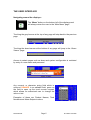
1
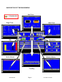
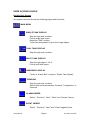
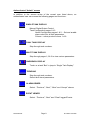
VMaC – 310 TANK MONITORING SYSTEM Site Operation and Maintenance Manual V1.02.02 PWO …………….. (Generic Issue) PAWCO Ltd, Unit J, Alanbrooke Industrial Park, Station Road, Topcliffe, Thirsk, Y07 3SB. Tel.01347 838080 Fax.01845 577800 WEB: www.pawco.co.uk, Email: [email protected] © PAWCO Ltd 2008 Table of Contents 1. INTRODUCTION 3 2. NORMAL OPERATION 4 3. FUNCTIONALITY 5 4. THE USER INTERFACE 6 5. NAVIGATION OF THE MAIN MENU 7 6. NAVIGATION OF THE SINGLE TANK DISPLAYS 8 7. USER ACCESS LEVELS 9 8. SYSTEM CONFIGURATION 11 9. SYSTEM TESTING AND MAINTENANCE 12 10. APPENDIX - TECHNICAL DATA SHEETS AND MANUALS 14 PWOXXXXXX Page 2 © PAWCO Ltd 2008 INTRODUCTION The VMaC–310 Tank Monitoring System provided by PAWCO Ltd, comprises of XX level probes, fitted in the top of the tanks 1 to 24. Dependent on your application these measuring devices can provide output of level, temperature and water level. They are manufactured to meet ATEX compliance (Certification EEx ia). Each of the tank probes is connected in series via a two pair cable to a data converter module inside the VMaC-310 enclosure. A local external isolator provides a 230v ac mains supply. A Beka 201 Ex unit may be fitted to provide galvanic separation between the power supply side of the system and a “Hazardous Area” (Zone 1) intrinsically safe BA484D Remote Display (Optional). No alteration, addition or connection of non EEx (ia) test equipment must be made to the Hazardous Area circuitry. Refer to the enclosed installation and operating manuals before any work or access to the system is undertaken. The 230v ac mains supply is protected by a local 30mA RCD and 6amp MCB inside the panel. A mains filter unit provides protection against mains born interference. All the internal devices, door indicators and switches are operated from an internal 24 volt dc power supply. The VMaC-310 unit drives a local alarm sounder and beacon via separate fused terminals. These are not ATEX approved units and are mounted outside the zoned area. (An ATEX option is available). A volt free relay interface is provided to enable connection to pump or valve control circuitry for each tank. PWOXXXXXX Page 3 © PAWCO Ltd 2008 NORMAL OPERATION Front Panel LED’s:Red “Power” LED indicating lamp:Should always be illuminated when the mains supply is switched on. This indicator shows the presence of 24 volt dc from the internal power supply unit. Yellow “Data” LED indicating lamps:Should be illuminated when the system is running; flashing when data is being read or written. Green “System” LED indicating lamps:Should be illuminated when the system is operational an running normally FUNCTIONALITY The Touch screen:When any of the tactile buttons along the left edge or the central display area is pressed the backlight will be activated to make the display visible. Note: A time out may be set that switches off the back light for the display panel after a period of inactivity. PWOXXXXXX Page 4 © PAWCO Ltd 2008 THE USER INTERFACE Navigating around the displays:- The “Menu” button on the bottom left of the display panel will always return the user to the “Main Menu” page. Touching the grey banner at the top of any page will step back to the previous page. Touching the alarm banner at the bottom of any page will jump to the “Alarm Viewer” page. Access to certain pages such as alarm and system configuration is restricted by entry of a user name and password. Any numeric or character string field which is coloured ORANGE is an editable field; press on the field to open up the touch screen keypad, which allows an authorised user to change the value or text. Examples of these are Product Names, Tank Numbers and Alarm Setpoint values. PWOXXXXXX Page 5 © PAWCO Ltd 2008 NAVIGATION OF THE MAIN MENU Dual Tank = A touch point Single Tank Multi Tank Bar Operations Active Alarms Historic Alarms Trending PWOXXXXXX Page 6 © PAWCO Ltd 2008 NAVIGATION OF SINGLE TANK DISPLAYS PWOXXXXXX Page 7 © PAWCO Ltd 2008 USER ACCESS LEVELS Default User Access Any system user can access the following pages and functions:MAIN MENU SINGLE TANK DISPLAY Step through tank numbers. Print a single tank report. Reset the “Shift” counter. Touch the tank graphic to go to the Large display. DUAL TANK DISPLAY Step through tank numbers. MULTI TANK DISPLAY Step through pages 1,2 & 3. Print a multi-tank report. BARGRAPH DISPLAY Touch on a tank “Bar” to jump to “Single Tank Display”. TRENDING Step through tank numbers. Select three trend parameters: Contents, Temperature, or Pressure. ALARM VIEWER Select: “Previous”, “Next”, “Mute” and “Accept” alarms. EVENT VIEWER Select: “Previous”, “Next” and “Clear” logged Events. PWOXXXXXX Page 8 © PAWCO Ltd 2008 Authenticated “Admin” access In addition to the access writes of the normal user listed above, an authenticated user can access the following pages and functions:- SINGLE TANK DISPLAY Manual Digital Output Control. Tank Configuration pages 1 & 2. Alarm Configuration pages 1 & 2. – Set and enable alarm values for all tank parameters Colours – select product colours 1 of 8 DUAL TANK DISPLAY Step through tank numbers. MULTI TANK DISPLAY Step through pages 1,2 & 3 to view various parameters. BARGRAPH DISPLAY Touch on a tank “Bar” to jump to “Single Tank Display”. TRENDING Step through tank numbers. Select three trend parameters. ALARM VIEWER Select: “Previous”, “Next”, “Mute” and “Accept” alarms. EVENT VIEWER Select: “Previous”, “Next” and “Clear” logged Events. PWOXXXXXX Page 9 © PAWCO Ltd 2008 Remote Access The VMaC-310 system can be remotely monitored or controlled when connected to a local network and/or internet access gateway. Using a standard Windows web browser the display unit can be accessed from a local or remote PC or internet enabled mobile phone. Use the mouse or pointer to navigate the displays as you would your finger directly on the real touch screen! The necessary network address will usually be assigned by the local IT department and set within the system by the system installer; usually as a “Favourite” or desktop icon on the PC. As well as direct access to the VMaC-310 displays, Log Data is available from the Main menu of the VMaC-310 web server; these can be opened with Excel to view historic data on many tank parameters. To access the Web browser on the VMaC-310 a username and password are required; these should only be allocated to necessary operational staff or maintenance personnel. PWOXXXXXX Page 10 © PAWCO Ltd 2008 SYSTEM CONFIGURATION Mechanical separation of the hazardous area wiring is maintained within the panel by use of a separate blue trunking and mechanical barrier. External “Hazardous Area” wiring to the tanks is identified by the use of blue steel wire armoured cable. Local Ticket Printer:A standard “Point of Sales” (POS) printer can be connected to the system to print a ticket report of the tank contents by pressing the “Print” button. An input terminal within the system enclosure provides the facility to produce an automatic print from a remote switch. This could be a gate switch, PIR sensor or push button, etc. Alarm notification by text or email:A GPRS modem module with an external aerial is connected to the main display panel and provides the facility of remote alarm notification by text alert or email. The details of designated recipient(s) can be programmed into the unit in the “System Configuration” page. Alarms which generate Text and/or email messages are:Tank Overfill, Hi alarm, Out of Hours Movement and Bund Level Alarms. The modem contains a standard SIM card and management of the SIM contract cost is the responsibility of the site. External Sounder:The external alarm sounder is a 24v dc multi-tone unit and can be set to produce alternative tones through various combinations of the DIP switch array inside the unit. The volume can also be adjusted. See the attached instruction leaflet for further details. External Beacon:The external flashing alarm beacon is a 24v dc xenon strobe type unit. There are no user adjustable parts. PWOXXXXXX Page 11 © PAWCO Ltd 2008 Internal Fuses:Any fuse that needs to be replaced should only be replaced with a fuse of the same type and rating. F1 = Protects the primary system components excluding the display. Master controller GPRS Modem Ethernet switch F2 = Protects the 310 display panel. F3 = Protects the Tank Probe circuits and interface modules. XX F4 = Protects the Remote Display components.(Option) BEKA 484D BEKA BA201 F5 = Protects the External output devices Alarm Sounder Alarm Beacon Output relay circuits Switch Input feed. Epson Printer (Option) SYSTEM TESTING AND MAINTENANCE The VMaC-310 system has an alarm test facility for the external alarm sounder and beacon. If a tank probe should go into fault mode or the system loses communication to any tank probe then the system will revert to a “Fail safe” mode and drive the indication for that tank to MAX – resulting in an alarm condition. PAWCO Ltd recommends that for maximum assurance, the system is checked annually and operation of the whole system verified and tank level accuracy confirmed against a series of check dips. PWOXXXXXX Page 12 © PAWCO Ltd 2008 Regular visual inspection of the panel, cabling and connections is recommended as part of a routine maintenance regime. Particular attention should be made to the mains electrical connections and protective earth conductors and connections as per BS 7671. The panel should be cleaned with a damp cloth only – Do not use solvents or abrasive cleaning materials, which may damage the unit. A protective screen overlay is fitted to the touch screen and replacements are available from PAWCO Ltd. For technical advice or assistance please contact PAWCO Ltd on 01347 838080 or via email: [email protected] PWOXXXXXX Page 13 © PAWCO Ltd 2008 APPENDIX PWOXXXXXX Page 14 © PAWCO Ltd 2008