1
MS20 GPS Receiver
User Manual
Issue: P03
Bulletin
Revision
Date
NS34-UM
P03
20 Jan 2011
2
1. DESCRIPTION............................................................................................................................................................3
1.1 Introduction.......................................................................................................................................... 3
1.2 MS20 Applications............................................................................................................................... 3
1.3 MS20 Features.................................................................................................................................... 3
2.
SPECIFICATION......................................................................................................................................................4-5
2.1 Performance ....................................................................................................................................... 4
2.2 Electrical Characteristics..................................................................................................................... 5
2.3 Absolute Maximum Ratings................................................................................................................. 5
2.4 Block Diagram..................................................................................................................................... 5
3. PHYSICAL CHARACTERISTICS............................................................................................................................6-8
3.1 Forms and Size................................................................................................................................... 6
3.2 Physical Interface Details.................................................................................................................... 7
3.3 Pin-Outs.............................................................................................................................................. 7
3.4 Solder Pad Size and Placement.......................................................................................................... 8
4.
SIGNAL DESCRIPTION.............................................................................................................................................9
4.1 Power Signal Descriptions................................................................................................................... 9
5.
SPECIAL CONSIDERATIONS.................................................................................................................................10
5.1 Power Enable....................................................................................................................................... 10
5.2 Reset.................................................................................................................................................... 10
5.3 Wake Up............................................................................................................................................... 10
5.4 Battery Supply...................................................................................................................................... 10
5.5 Firmware Updating............................................................................................................................... 10
6.
USER INTERFACE MESSAGES.........................................................................................................................11-22
6.1 NMEA Protocol.................................................................................................................................. 11
6.2 NMEA Extensions............................................................................................................................. 11
6.3 General NMEA Format...................................................................................................................... 11
6.4 $GPGGA........................................................................................................................................... 12
6.5 $GPGLL............................................................................................................................................ 13
6.6 $GPGSA............................................................................................................................................ 14
6.7 $GPGSV............................................................................................................................................ 15
6.8 $GPVTG............................................................................................................................................ 16
6.9 $GPZDA............................................................................................................................................ 16
6.10 $GPRMC........................................................................................................................................... 17
6.11 $PMST02.....................................................................................................................................17-18
6.12 $PMST100........................................................................................................................................ 18
6.13 $PMST200........................................................................................................................................ 19
6.14 $PMST12.....................................................................................................................................19-20
6.15 $PMST14.......................................................................................................................................... 20
6.16 $PMST10.......................................................................................................................................... 21
6.17 $PMST09.......................................................................................................................................... 22
7.
TAPE AND REEL SPECIFICATIONS.......................................................................................................................23
8.
SOLDER PROFILE...................................................................................................................................................24
9.
ORDERING INFORMATION.....................................................................................................................................24
10.
APPENDICES......................................................................................................................................................25-31
NS34-DS MS20 Data Sheet
Copyright ©2011 NavSync Ltd. All Rights Reserved
Rev P03
Date: 01/20/11
Specifications subject to change without notice.
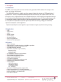
1. Description
1.1 Introduction
The MS20 uses the physical form factor of the earlier generation CW20 module with changes in the
power and voltage requirements.
The MS20 GPS module is a highly sensitive, compact single chip solution for GPS applications. It
includes an RF receiver, complete baseband processor, flash memory and a power control unit. The
RF receiver uses a single conversion low-IF digital architecture, with the high-level integration leaving a
few off-chip matching and decoupling components, minimizing system cost. The baseband processor
is controlled by adaptive signal processing, and the navigation firmware is optimized for execution
on a low power microprocessor. Optimal signal acquisition and tracking strategy are enabled by
sophisticated adaptive control algorithms.
Sophisticated adaptive control algorithms provide optimal signal acquisition/tracking strategy.
1.2 Applications
• PND
•
•
•
•
•
•
•
Mobile Phone
UMPC
Vehicle Tracking
Asset Tracking
Personnel Tracking
DSC and GPS Related
Marine and Timing Navigation
1.3 Features
• GPS L1 C/A code
• High sensitivity of -159 dBm in tracking & -144 dBm in acquisition
• Build in power-on-reset and calibration circuits
• Assisted/autonomous operation
• Fast TTFF in all modes ( a typical outdoor )
• hot-start in 1.5s,
• warm-start in 32s
• cold-start in 35s
• Up to 60,000 simultaneous search windows
• 48 acquisition & 12 tracking channels
• SBAS (WAAS/EGNOS/MSAS) capable
• Support standard NMEA-0183
• TCXO & RTC integrated
• Integrate a high-performance MIPS M4K CPU
• Integrated a 512 kB NOR flash memory
• Easy to integrate
• UART data interface
• 3.3V tolerant I/O pins
• 1 PPS (200 ns RMS)
• 3.2 - 5V Supply
• Operates at 1.2V/3.0V (core/IO), integrate LDO
• Battery backed RAM & RTC and direct connection
• 0.18um CMOS for RF and 0.11um CMOS for Baseband
• Avg current (33mA @ 3.3V, 29mA @ 5V)
• 21.0 x 16.44 x 2.82 mm
NS34-DS MS20 Data Sheet Rev P03
Copyright ©2011 NavSync Ltd. All Rights Reserved
Date: 01/20/11
Specifications subject to change without notice.
3
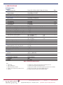
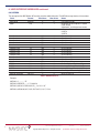
2. SPECIFICATIONS
2.1 Performance
Physical
Module Dimensions
Electrical
Supply Voltages
Operating Temperature Range
Storage Temperature Range
GPS Performance
GPS Channels
Frequency
TTFF Cold Start
TTFF Warm Start
TTFF Hot Start Re-acquisition time
Acquisition Sensitivity (fix not available) Acquisition Sensitivity (dBm)
Tracking Sensitivity (dBm)
Acquisition Sensitivity SBAS Satellites (dBm)
Tracking Sensitivity SBAS Satellites (dBm)
Static Accuracy (without SBAS)
Static Accuracy (with SBAS)
Maximum Horizontal Speed
Maximum Altitude
Maximum Acceleration, Jerk
Power
During acquisition (fully active) @ 3.3V
While tracking (fully active) @ 3.3V
During Sleep Mode (NVDD)
VBAT Current
Interfaces
I/O Port
Protocols
Antenna
Configuration Supported
Impedance
Voltage
21mm (D) x 16.44mm (W) x 2.82mm (H) ±.2mm
3V3 (NVDD), 2V5 (VBAT)
-30°C to 70°C
-40°C to 85°C
Notes
1
12 tracking (48 acquisition)
1575.42 MHz – L1 C/A Code
34 seconds
32 seconds
1.5 seconds
<1 seconds
TTFF (Hot) with all signals at -138 dBm: 30 s
-144 dBm
-159 dBm
TBD
TBD
50% Confidence (CEP)
1.7 m
95% Confidence
2.9 m
50% Confidence (CEP)
1.2 m
95% Confidence
2.4 m
515 m/s (1000 Knots)
18 Km (60000 feet)
4 g, 7 g/s
2, 8
2, 8
2, 8
3
4
5
6
7
7
8
9
10
10
145 mW
110 mW
TBD
25µa @ 3v
UART x 2 (9600 8N1)
NMEA 0183
Active or Passive
50Ω 2.8 - 3.1V
Table 1. Performance Specifications
4
Notes:
1. Typical listed
2. These are RMS values
3. Maximum Sensitivity -147 dBm
4. Simulator Test, all signals at specified power level.
5. Estimated
6.
7.
8.
9.
10.
Simulator Test, continuous fix with all signals at specified power level.
Simulator Test with signal at specified power level.
Open-sky, 24 hrs statistic, active antenna (signal range is between 30 to 49 dB/Hz).
Open sky, 24 hrs statistic, active antenna (WAAS signal used).
Limited by International Traffic in Arms Regulation (ITAR)
NS34-DS MS20 Data Sheet
Copyright ©2011 NavSync Ltd. All Rights Reserved
Rev P03
Date: 01/20/11
Specifications subject to change without notice.
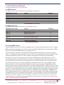
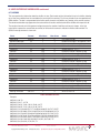
2.2 Electrical Characteristics
2.2.1 Absolute Ratings
Symbol
NVDD
VBAT
Notes:
Min
-0.2
-0.2
Typ
-
-
Max
5.5
5.5
Units
V
V
Notes
Units
°C
V
V
Notes
Max
Units
Notes
2.9 ±5%
-
V
1
1. Absent a battery, this should be connected to NVDD. Below minimum voltage module will not power up.
2.2.3 Recommended
Symbol
Temp
NVDD
VBAT
Notes:
Min
-30
3.2
2.2
Typ
25
3.6
3.6
Max
+70
5.0
5.0
1
1. Absent a battery, this should be connected to NVDD. Below minimum voltage module will not power up.
2.2.3 CMOS Interface Levels
Symbol
Min
VCC30
-
VOH
VCC30 -0.1
-
-
V
1
VOL
-
-
0.1
V
1
Output Current
-
-
4.0
mA
VIH
2.5
-
-
V
VIL
-
0.8 V
1
Input Capacitance
-
5
-
pF
Input current
-
-
1.0
uA
Notes: Typ
1
1. Digital Inputs and Outputs are 3V CMOS.
Tables 2. Electrical Characteristics
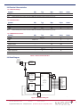
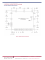
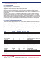
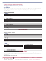
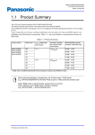
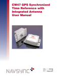
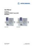
2.3 Block Diagram
Antenna
Connection
RF GND 15
16
RF IN
RF GND 17
Antenna
Power
LNA
SAW
GPS RF
Front End
& LNA
GPS IF
Interface
Main
Clock
TCXO
RTC
Clock
32 kHz
XTAL
GPS
Baseband
Processor
MS20
Memory
Interface
Flash
8MBit
AVDD 3.0V
DVDD 1.2V
Digital I/O
1. NVDD
2. TX
3. RX
4. GND
5. RESET #
6. VBAT
7. NC
8. 1PPS
9. RX
10. TX
11. POWERON
12. EVENTIN
13. GPIO
14. WAKEUP
Volt
Reg
Figure 1. MS20 Block Diagram
NS34-DS MS20 Data Sheet Rev P03
Copyright ©2011 NavSync Ltd. All Rights Reserved
Date: 01/20/11
Specifications subject to change without notice.
5
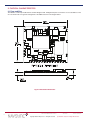
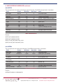
3. PHYSICAL CHARACTERISTICS
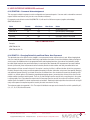
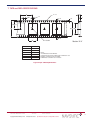
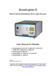
3.1 Form and Size
The MS20 is a multi-chip module built on an FR4 fiberglass PCB. All digital and power connections are via castellations on the
21 x 16.44 mm PCB. The general arrangement of the MS20 is shown in the diagram below.
Figure 2: Mechanical Dimensions
6
NS34-DS MS20 Data Sheet
Copyright ©2011 NavSync Ltd. All Rights Reserved
Rev P03
Date: 01/20/11
Specifications subject to change without notice.
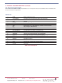
3. PHYSICAL CHARACTERISTICS continued
3.2 Physical Interface Details
The interface to the MS20 is via 0.90 mm castellations on a 1.27 mm pitch. There are 25 castellations in all. The details of the
interface connections are given below.
3.3 Pin Out
1
NVDD
Primary Supply (3.2 - 5.0V)
2
TX (PRIMARY)
Serial Data Transmit from Module (NMEA Output 9600 8N1)
3
RX (PRIMARY)
Serial Data Receive to Module
4
GND
5
RESET#
6
VBAT
7
NC
8
1PPS
9
RX (SECONDARY) Serial Data Receive to Module (CW20:DSU_RX)
10
TX (SECONDARY)
Serial Data Transmit from Module (CW20:DSU_TX)
11
POWERON
Ground to Turn Internal Regulators Off (CW20:DSUEN)
12
EVENTIN
13
GPIO
14
WAKEUP
Pull High to Suspend.
15
RF GND
RF Ground
16
RF IN
17
RF GND
Ground
Active Low Device Reset
Backup Supply (2.2 - 5.0V) Required, if no battery connect to primary
Not Connected (CW20:DSUMUX)
One Pulse Per Second
Event Input with Custom Firmware (CW20:DSUBRE)
General Purpose IO with Custom Firmware (CW20:DSUACT)
RF Input, with ~3.0V DC Bias for Active Antenna
RF Ground
Table 3. Pin-Out Descriptions
NS34-DS MS20 Data Sheet Rev P03
Copyright ©2011 NavSync Ltd. All Rights Reserved
Date: 01/20/11
Specifications subject to change without notice.
7
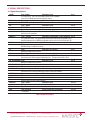
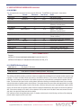
3. PHYSICAL CHARACTERISTICS continued
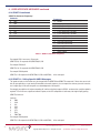
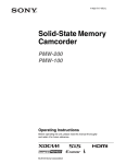
3.4 Solder Pad Size and Placement
.176766
(4.48986mm)
.3001979
(7.62503mm)
.300196
(7.62498mm)
.05844
(1.48438mm)
.076798
(1.95067mm)
.75616
(1.92065mm)
.19882
(5.05003mm)
.198818
(5.04998mm)
.150786
(3.82996mm)
.25197
(6.40004mm)
.130778
(3.32176mm)
.128414
(3.26172mm)
.05844
(1.48438mm)
.12716
(3.22986mm)
Figure 3: Solder Pad Size and Placement
8
NS34-DS MS20 Data Sheet
Copyright ©2011 NavSync Ltd. All Rights Reserved
Rev P03
Date: 01/20/11
Specifications subject to change without notice.
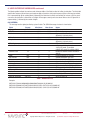
4. SIGNAL DESCRIPTIONS
4.1 Signal Descriptions
NVDD
Type: Power
Direction: Input
Pin 1
The supply input. This 3.3V input supplies power to RF and digital
sections of the MS20 and should be properly filtered.
TX
Type: Signal
Direction: Output
Pin 2
The UART transmit signal for the MS20.
RX
Type: Signal
Direction: Input
Pin 3
The UART receive signal for the MS20.
GND
Type: Power
Direction: Input/Output
Pin 4
The ground pin for the MS20. The return path of the NVDD and ground
reference for all signal pins.
RESET #
Type: Control
Direction: Input/Output - Open Collector Pin 5
The system reset signal. This asynchronous signal must be held low for a minimum of 1ms
following valid power on the NVDD pin to generate a device reset. Internal 47k pull-up to 3V
VBAT
Type: Power
Direction: Input
Pin 6
The backup battery supply input. Minimum voltage of 2.2V required to maintain
NVRAM settings, and power on device.
nc
Type: Direction: No connect
Pin 7
Debug and programming interface.
GPIO <4>
Type: Signal
Direction: Input/Output
Pin 8
Blinks for 1ms every time traffic is generated on the UART interface. May be
left unconnected. General purpose input/output pin. The signal return path is Pin 4.
RX_SECONDARYType: Direction: Input
Pin 9
Debug and programming interface.
TX_SECONDARY Type: Direction: Output
Pin 10
Debug and programming interface.
POWER_ON
Type: Direction: Input - Open Collector
Pin 11
Ground to turn off, normally pulled high. Internal 47k pull-up to NVDD
EVENT_IN
Type: Direction: Input
Pin 12
Event input with custom firmware
GPIO
Type: Direction: Output
Pin 13
General Purpose IO with custom firmware..
WAKEUP
Type: Power
Direction: Input
Pin 14
Pull high to suspend. Internal 47k pull-down to GND
GND
Type: Power
Additional GND Pins for the MS20
Pins 15, 17-25
ANT
Type: Antenna
Primary Antenna Connection
Pin 16
~ 3V DC Bias
Table 4. Signal Descriptions
NS34-DS MS20 Data Sheet Rev P03
Copyright ©2011 NavSync Ltd. All Rights Reserved
Date: 01/20/11
Specifications subject to change without notice.
9
5. SPECIAL CONSIDERATIONS
5.1 Power Enable
The POWERON (11) pin is pulled high internally and gates the enable of the internal regulators. When high, the regulators will
be enabled. The user may clamp this pin to ground to disable the internal regulator. A side effect of this, and to effectively perform a Power-On-Reset (POR), the Reset pin will be clamped to zero during the time POWERON is low, and for at least 100 ms
after POWERON is high as the regulator resumes normal operation. The POR circuit is monitoring the output from the internal
regulators, not the NVDD supply.
Holding POWERON will cause the least amount of power to be consumed by the MS20 via the NVDD pin. The CPU, flash, RF
front end and TCXO will be powered down. The RTC and its oscillator will continue to be powered from the VBAT pin.
5.2 Reset
The RESET# (5) pin is an open collector pin designed to be clamped low by external circuitry when a reset is required. It will
also be clamped low internally by the MS20 when the output from the internal regulator is less than 2.7V. This clamping will
persist for at least 100ms after the supply has recovered. This behavior is designed to ensure the correct startup of the receiver. Be aware that connecting RESET# to other external reset inputs will result in the device resetting as well, or be held in
reset, when the power to the MS20 is removed or disabled. This situation may occur in several ways: NVDD is currently below
the drop out threshold of the regulator, which is below the minimum input voltage specification; NVDD or VDD30 (2.9V) has
browned out because the supply has drooped or otherwise failed to provide enough current on demand; the POWERON pin has
been, or is, pulled low; or external circuitry, either a POR or GPIO, is initiating or holding the device in reset.
Note: The internal supplies on the MS20 are not exposed to the user of the device.
5.3 Wake Up
The WAKEUP (14) Pin is pulled low internally, driving this pin high will cause the MS20 to enter the sleep/suspend state. The
MS20 will exit the sleep/suspend state when the pin is released or driven low.
5.4 Battery Supply
GPS receivers use batteries to maintain time and non-volatile memory. In order to speed up reacquisition, GPS receivers want
to maintain time/date/location information along with almanac data. The satellite constellation is in constant motion so in order
to predict which satellites will be visible, you need to know what time it is, where you are (approximately), and have a way to
compute the orbital position of all the satellites within the constellation. Using this information the receiver can commit correlators to search for satellites that are in-view, and improve the time to first fix (TTFF). That said, today’s receivers can search the
signal space for the satellite signals much more rapidly than when the system was initially conceived. Non-volatile memory can
also hold ephemeris and almanac information which would otherwise have to be demodulated from the slow data signal. The
GPS receiver will still be able to function without this information at startup. It will just have to do more work and will typically
take longer to do so.
Given the separation of the supplies, and to permit the greatest flexibility in application circuits, power needs to be present on
VBAT for the MS20 to function. Without power, the MS20 will not start.
In some implementations it is not desirable to have a battery or super capacitor in the receiver sub-system. In these situations
VBAT and NVDD should be connected together. When the main supply is lost, any time, location and associated data previously
held will be lost. The receiver can regenerate and reacquire this data, although it will take longer.
With a battery (primary cell, or rechargeable) or super capacitor, the voltage at VBAT should be 2.2 V or higher for the MS20 to
function.
5.5 Firmware Updating
In order to perform firmware updates, or apply custom firmware, the secondary RX (9) and TX (10) pins should be exposed to
a header. The software to update the device runs on a PC. These pins are not RS-232 compatible so direct connection to a PC is
not possible, although there are several level converters and USB type adapters to achieve this. It is suggested that the header
match off-the-shelf or other converters you are currently using.
10
NS34-DS MS20 Data Sheet
Copyright ©2011 NavSync Ltd. All Rights Reserved
Rev P03
Date: 01/20/11
Specifications subject to change without notice.
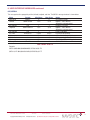
6. USER INTERFACE MESSAGES
The following application protocols are implemented
6.1 NMEA Protocol
The MS20 software is capable of supporting the following NMEA message formats:
NMEA Message Prefix $GPRMC $GPGGA $GPGLL $GPGSA $GPGSV $GPVTG $GPZDA Format Recommended minimum specific GNSS data
GPS fix data
Geographic position latitude / longitude
GNSS DOP and active satellites
Satellites in view
Velocity and track over ground
Date and time
Direction
Out
Out
Out
Out
Out
Out
Out
Table 5 NMEA Messages Summary
6.2 NMEA Extensions
The MS20 software is capable of supporting the following NMEA extensions:
NMEA Extension Prefix Format Direction
$PMST02 Software reset In
$PMST12
NMEA message rate control
In
$PMST10
NMEA Baud rate control
In
$PMST09
Non-voltatile settings
In
$PMST14
Polling specific NMEA messages
$PMST100
Software version information
Out
$PMST200
Command acknowledgement
Out
In
Table 6 Extended Messages
6.3 General NMEA Format
The general NMEA format consists of an ASCII string beginning with a ‘$’ character and terminated with a <CR><LF> sequence.
NMEA standard GPS messaged begin with ‘GP’ then a 3 letter message identifier. MS20 specific messages being with ‘$PMST’
followed by a 2 digit number. NMEA proprietary message begin with a ‘P’.
The message header is followed by a comma delimited list of fields optionally terminated with a checksum consisting of an
asterisk ‘*’ and a 2 digit hex value representing the checksum. There is no comma preceding the checksum field. All messages
emitted by the MS20 have checksums, the checksum should be verified before using or relying on the data provided.
When present, the checksum is calculated as a byte wise exclusive OR (XOR) of the characters between the ‘$’ and the ‘*’.
As an ASCII representation, the number of digits in each number will vary depending on the number and precision, hence the
record length will vary. Certain fields may be omitted (blank) if they are not used or available. In this case the field position is
reserved using commas to ensure the correct interpretation of subsequent fields. There are no spaces in NMEA messages.
When parsing data, the routines should be robust and flexible to account for precision changes. The NMEA format was designed as a common interface to position reporting devices in the 1980’s including TRANSIT and LORAN. The format of latitude
and longitude was specifically designed for easy transfer to LED 7-segment type display devices with little translation by simple
processors. The format of degrees and minutes is not immediately intuitive and needs to be decomposed to arrive at a decimal
degrees form used in computer/software navigation applications. The NMEA messages report position in a DDDMM.mmmm
form. The MM.mmm portion needs to be divided by 60 to compute the fractional degrees and the DDDxx integer portion needs
to be divided by 100. The sign is then negated if the hemisphere is ‘S’outh of the Equator or ‘W’est of the Greenwich Meridian,
depending on the latitude or longitude. Incorrect decomposition will produce results with significant offsets. Example code is
available upon request. The validity field of the specific NMEA message should always be checked prior to using location information. The GPS constellation uses the WS85 datum.
NS34-DS MS20 Data Sheet Rev P03
Copyright ©2011 NavSync Ltd. All Rights Reserved
Date: 01/20/11
Specifications subject to change without notice.
11
6. USER INTERFACE MESSAGES continued
The following tables indicate the maximum and minimum widths of the fields to allow for buffer size allocation. The field width
specifications represent the minimum and maximum digits of precision which must be present. When a field may be omitted,
this is represented by (0) for omitted (blank), followed by the data when the field is not emitted. For instance, (0) 3 for checksum means the checksum is either blank, or 3 digits. All messages currently emit a checksum. When a value is signed this is
represented by (-) followed by the number of digits.
6.4 $GPGGA
This message transfers global positioning system fix data. The $GPGGA message structure is shown below:
Field
Format
Min Chars
Max Chars
Message ID
$GPGGA
6
6
UTC Time hhmmss.sss
2,2,2.3
2,2,2.3
Latitude
ddmm.mmmm
2,2.4
2,2.6
N/S Indicator
char
1
1
Longitude
dddmm.mmmm
3,2.4
3,2.6
E/W Indicator
char
1
1
Position Fix Indicator
int
1
1
Satellites Used
int
2
2
HDOP
float
1.1
3.1
MSL Altitude
float
1.1
5.1
Units
char
1
1
Geoid Separation
float
(0)1
4
Units
char 1
1
Age of Differential
int
(0)1
5
Corrections
Differential Reference
int
(0)4
4
Station ID
Checksum
*xx
(0)3
3
Message Terminator
<CR><LF>
2
2
Notes
GGA protocol header
Fix time to 1ms accuracy
Degrees * 100 + Minutes
(Nominally 4 decimal places)
N=North, or S=South
Degrees * 100 + Minutes
(Nominally 4 decimal places)
E=East, or W=West
0=Fix not available or invalid
1=GPS SPS mode. Fix available
2=DGPS SPS mode. Fix available (SBAS)
Number of satellites used to calculate fix
(00-12)
Horizontal Dilution of Precision
Altitude above Mean Sea Level
M Stands for Meters/Metres
Separation from Geoid (WGS84), can be blank
M Stands for Meters/Metres
Age in seconds, Blank (NULL) on MS20
SBAS operation reflected in fix indicator
Blank (NULL), Zero, or Station ID
2 Hex Digits, XOR sum of payload
ASCII 13, ASCII 10
Table 7. GPGGA Field List
Examples:
$GPGGA,215139.980,0000.0000,N,00000.0000,E,0,00,0.0,,M,,M,,0000*61
$GPGGA,215204.000,4147.9057,N,08816.2623,W,1,05,3.4,247.8,M,-43.5,M,,0000*65
$GPGGA,215253.000,4147.9055,N,08816.2649,W,2,08,1.2,242.1,M,-43.5,M,,0000*6F
12
NS34-DS MS20 Data Sheet
Copyright ©2011 NavSync Ltd. All Rights Reserved
Rev P03
Date: 01/20/11
Specifications subject to change without notice.
6. USER INTERFACE MESSAGES continued
6.5 $GPGLL
This message transfers geographic position, latitude, longitude, and time. The $GPGLL message structure is shown below:
Field
Format
Min Chars
Max Chars
Message ID
$GPGLL
6
6
Latitude
ddmm.mmmm
2,2.4
2,2.6
N/S Indicator
char
1
1
Longitude
dddmm.mmmm
3,2.4
3,2.6
E/W Indicator
char
1
1
UTC Time
hhmmss.sss
2,2,2.3
2,2,2.3
Status
char
1
1
Mode Indicator
char
1
1
Checksum
*xx
(0)3
3
Message Terminator
<CR><LF>
2
2
Notes
GLL protocol header
Degrees * 100 + Minutes
(Nominally 4 decimal places)
N=North, or S=South
Degrees * 100 + Minutes
(Nominally 4 decimal places)
E=East, or W=West
Fix time to 1ms accuracy
A=Data Valid, V=Data Invalid
A=Autonomous, N=Data Not Valid
2 Hex Digits, XOR sum of payload
ASCII 13, ASCII 10
Table 8. GPGLL Field List
Examples:
$GPGLL,0000.0000,N,00000.0000,E,215139.98,V,N*7D
$GPGLL,4147.9049,N,08816.2642,W,215207.00,A,A*7F
NS34-DS MS20 Data Sheet Rev P03
Copyright ©2011 NavSync Ltd. All Rights Reserved
Date: 01/20/11
Specifications subject to change without notice.
13
6. USER INTERFACE MESSAGES continued
6.6 $GPGSA
This message transfers DOP (Dilution Of Precision) and active satellite information. The $GPGSA message structure is shown below:
Field
Format
Min Chars
Max Chars
Message ID
$GPGSA
6
6
Mode
char
1
1
Mode
int
1
1
Satellites Used
int
(0)2
2
Satellites Used
int
(0)2
2
Satellites Used
int
(0)2
2
Satellites Used
int
(0)2
2
Satellites Used
int
(0)2
2
Satellites Used
int
(0)2
2
Satellites Used
int
(0)2
2
Satellites Used
int
(0)2
2
Satellites Used
int
(0)2
2
Satellites Used
int
(0)2
2
Satellites Used
int
(0)2
2
Satellites Used
int
(0)2
2
PDOP
float
(0)1.1
3.1
HDOP
float
(0)1.1
3.1
VDOP
float
(0)1.1
3.1
Checksum
*xx
(0)3
3
Message Terminator
<CR><LF>
2
2
Notes
GSA protocol header
M=Manual, forced to operate in selected
mode (2D/3D)
A=Automatic, switching between modes
1=Fix not available
2=2D Fix
3=3D Fix
SV on Channel 1
SV on Channel 2
SV on Channel 3
SV on Channel 4
SV on Channel 5
SV on Channel 6
SV on Channel 7
SV on Channel 8
SV on Channel 9
SV on Channel 10
SV on Channel 11
SV on Channel 12
Position Dilution of Precision (3D)
Horizontal Dilution of Precision (2D)
Vertical Dilution of Precision (Up/Down)
2 Hex Digits, XOR sum of payload
ASCII 13, ASCII 10
Table 9. GPGSA Field List
Examples:
$GPGSA,A,1,,,,,,,,,,,,,,,*1E
$GPGSA,A,2,02,04,05,,,,,,,,,,4.7,4.6,0.9*38
$GPGSA,A,3,01,04,13,16,20,23,24,25,,,,,1.8,1.2,1.4*3F
$GPGSA,A,3,05,06,09,10,15,18,21,22,27,29,51,,1.3,0.7,1.1*38
14
NS34-DS MS20 Data Sheet
Copyright ©2011 NavSync Ltd. All Rights Reserved
Rev P03
Date: 01/20/11
Specifications subject to change without notice.
6. USER INTERFACE MESSAGES continued
6.7 $GPGSV
This message transfers information about the satellites in view. (Each record contains information for up to 4 satellites, allowing
up to 16 or more satellites from the constellation that are visible to the receiver.) The list may include one or more geostationary
SBAS satellites. The data is not guaranteed to be tied to specific channels and satellites may come/go as the receiver searches.
The azimuth and elevation only appear when the receiver knows its location and the location of the satellites with respect to itself.
The number of records sent will expand and collapse based on the number of satellites and channels changes. In the final
record of the sequence the unused fields are omitted, or left blank with commas to indicate the field has been omitted. The
$GPGSV message structure is shown next:
Field
Message ID
Number of Messages
Message Number
Satellites in view
Satellite ID
Elevation
Azimuth
SNR
Satellite ID
Elevation
Azimuth
SNR
Satellite ID
Elevation
Azimuth
SNR
Satellite ID
Elevation
Azimuth
SNR
Checksum
Message Terminator
Format
$GPGSV
int
int
int
int
int
int
int
int
int
int
int
int
int
int
int
int
int
int
int
*xx
<CR><LF>
Min Chars
6
1
1
1
0(2)
0(1)
0(1)
0(1)
0(2)
0(1)
0(1)
0(1)
0(2)
0(1)
0(1)
0(1)
0(2)
0(1)
0(1)
0(1)
(0)3
2
Max Chars
6
1
1
2
2
2
3
2
2
2
3
2
2
2
3
2
2
2
3
2
3
2
Notes
GSV protocol header
Number of messages in the sequence 1 to 4
Sequence number of message in current burst
Number of satellites in view, this list
Satellite vehicle (1, 5, 9, ..)
Elevation of satellite in degrees (0..90)
Azimuth of satellite in degrees (0..360)
Signal to noise ratio in dB/Hz, null not tracking
Satellite vehicle (2, 6, 10, ..)
Elevation of satellite in degrees (0..90)
Azimuth of satellite in degrees (0..360)
Signal to noise ratio in dB/Hz, null not tracking
Satellite vehicle (3, 7, 11, ..)
Elevation of satellite in degrees (0..90)
Azimuth of satellite in degrees (0..360)
Signal to noise ratio in dB/Hz, null not tracking
Satellite vehicle (4, 8, 12, ..)
Elevation of satellite in degrees (0..90)
Azimuth of satellite in degrees (0..360)
Signal to noise ratio in dB/Hz, null not tracking
2 hex digits, XOR sum of payload
ASCII 13, ASCII 10
Table 10. GPGSV Field List
Examples:
$GPGSV,1,1,00*79
$GPGSV,1,1,01,17,,,41*7B
$GPGSV,2,1,08,01,,,51,02,,,50,12,,,50,04,,,49*7F
$GPGSV,2,2,08,05,,,51,13,,,46,18,,,23,10,,,50*7C
$GPGSV,3,1,12,21,63,309,51,27,17,133,46,26,04,206,45,18,47,271,50*7E
$GPGSV,3,2,12,05,19,068,47,22,13,260,47,29,34,197,49,06,09,322,41*79
$GPGSV,3,3,12,15,63,074,53,10,08,070,44,09,09,146,44,51,37,207,51*72
$GPGSV,4,1,14,20,70,191,51,23,59,339,50,16,47,078,50,13,30,305,50*7C
$GPGSV,4,2,14,24,23,264,49,01,17,091,49,25,16,052,49,27,14,245,25*7C
$GPGSV,4,3,14,04,11,304,49,11,04,200,,51,48,161,,48,47,205,*75
$GPGSV,4,4,14,35,42,218,,47,12,254,*74
NS34-DS MS20 Data Sheet Rev P03
Copyright ©2011 NavSync Ltd. All Rights Reserved
Date: 01/20/11
Specifications subject to change without notice.
15
6. USER INTERFACE MESSAGES continued
6.8 $GPVTG
This message transfers the velocity and tracking over ground information. The $GPVTG message format is shown below.
Field
Format
Min Chars
Max Chars
Message ID
$GPVTG
6
6
Course (True)
float
1.1
3.2
Reference
char
0(1)
1
Course (Magnetic)
blank
(0)
(0)
Reference
char
0(1)
1
Speed
float
1.1 4.2 Units
char
0(1)
1
Speed
float
1.1
4.2
Units
char
0(1)
1
K Stands for kilometers per hour
Mode Indicator
char
1
1
A=Autonomous, N=Data not valid
Checksum
*xx
(0)3
3
2 hex digits, XOR sum of payload
<CR><LF>
2
2
ASCII13, ASCII10
Message Terminator
Notes
VTG protocol header
Measured heading in degrees
T Stands for true heading
Not used – magnetic heading in degrees
M Stands for magnetic
Speed in knots
N stands for nautical (knots) miles per hour
Speed in KPH
Table 11 GPVTG Field List
Examples:
$GPVTG,0.0,T,,M,0.0,N,0.0K,N*02
$GPVTG,0.0,T,,M,0.0,N,0.0,K,A*0D
$GPVTG,179.98,T,,M,97.09,N,179.81,K,A*02
$GPVTG,315.03,T,,M,97.23,N,180.07,K,A*08
6.9 $GPZDA
This message transfers the internal timing information. The $GPZDA message format is shown below.
Field
Format
Min Chars
Max Chars
Message ID
$GPZDA
6
6
UTC Time
hhmmss.sss
2,2,2.3
2,2,2.3
UTC Day
dd
2
2
01 to 31, Day of Month
UTC Month
mm
2
2
01 to 12, Month of Year
UTC Year
constellation)
yyyy
4
4
1980-2079 (Likely to exceed viability of
int
(-)2
(-2)
Not used – 00
unsigned
2
2
Not used – 00
*xx
(0)3
3
2 hex digits, XOR sum of payload
<CR><LF>
2
2
ASCII 13, ASCII 10
Local Zone Hours
Local Zone Minutes
Checksum
Message Terminator
Notes
ZDA protocol header
Internal time to 1ms accuracy
Table 12. GPZDA Field List
Examples:
$GPZDA,215139.980,16,11,2009,00,00*56
16
NS34-DS MS20 Data Sheet
Copyright ©2011 NavSync Ltd. All Rights Reserved
Rev P03
Date: 01/20/11
Specifications subject to change without notice.
6. USER INTERFACE MESSAGES continued
6.10 $GPRMC
This message transfers recommend minimum specific GNSS data. The $GPRMC message format is shown below:
Field
Format
Min Chars
Max Chars
Message ID
$GPRMC
6
6
UTC Time
hhmmss.sss
2,2,2.3
2,2,2.3
Status
char
1
1
Latitude
ddmm.mmmm
2,2.4
2,2.6
N/S Indicator
char
1
1
Longitude
dddmm.mmmm
3,2.4
3,2.6
E/W Indicator
char
1
1
Speed Over Ground
float
1.1
5.3
Course Over Ground
float
1.1
3.2
Date
ddmmyy
2,2,2
2,2,2
Magnetic Variation
blank
(0)
(0)
E/W Indicator
blank
(0)
(0)
Mode Indicator
char
1
1
Checksum
*xx
(0)3
3
Message Terminator
<CR><LF>
2
2
Notes
RMC protocol header
Fix time to 1ms accuracy
A=Data Valid, V=Data Invalid
Degrees * 100 + Minutes
(Nominally 4 decimal places)
N=North, or S=South
Degrees * 100 + Minutes
(Nominally 4 decimal places)
E=East, or W=West
Speed Over Ground (SOG) in knots
(1 Knot = 1852 m)
Course Over Ground (COG) in degrees
Current Date, 1980-2079
Not Used
A=Autonomous, N=Data Not Valid
2 Hex Digits, XOR sum of payload
ASCII 13, ASCII 10
Table 13. GPRMC Field List
Examples:
$GPRMC,215139.980,V,0000.0000,N,00000.0000,E,0.0,0.0,161109,,,N*74
$GPRMC,215207.000,A,4147.9049,N,08816.2642,W,0.0,0.0,161109,,,A*76
6.11 $PMST02 Software Reset
$PMST02,0*04
HOT (Device is Restarted)
$PMST02,48*38
WARM (Device is restarted, invalidate ephemeris)
$PMST02,58*39
COLD (Device is restarted, invalidate ephemeris, and position)
Table 14. $PMST02 Software Reset
The satellite constellation provides a continuous stream of navigation data modulated on to the pseudo random sequence ranging signal. This data is encoded at 50 bits per second, as five 300 bit sub frames. Three of these subframes contain ephemeris
information, which expresses the position of the satellite at a given time, and coefficients to extrapolate the position into the
future. The other two sub frames contain a rolling index of other data including a constellation wide almanac that can roughly
estimate the location of satellites months into the future. If the receiver knows the current time and rough location it can make
approximations about visible satellites from that time/location, effectively halving the search space required to acquire satellite
signals. Once the receiver has aquired a satellite it will then attempt to demodulate the data signals and recover the ephemeris
data. If the receiver already has this data it will save between 18-36 seconds and will be able to make measurements immediately after it has signal and timing lock with the satellite.
Each subframe contains timing information, both in it’s header, and instrincally in the bit timings, and those of the underlying
pseudo random sequence and the carrier itself.
NS34-DS MS20 Data Sheet Rev P03
Copyright ©2011 NavSync Ltd. All Rights Reserved
Date: 01/20/11
Specifications subject to change without notice.
17
6. USER INTERFACE MESSAGES continued
6.11 $PMST02 continued
In this context the receiver can be reset in several ways.
A HOT reset is where all the hardware is restarted and the signal is then reacquired. Information about the current time, location
and ephemeris is retained in RAM to permit a quick re-establishment of a GPS fix.
A WARM reset is one where additional information is invalidated. Primarily, the ephemeris data providing information of the
current/future estimations of the satellites position. Once the receiver re-acquires the satellite(s), it will have to extract the
ephemeris data, which will add 18-36 seconds of additional delay in ideal conditions, before it can provide measurements into
the solution engine.
A COLD reset is similar to a hard start of the receiver when no supplemental data is available. The absence of position and/
or time means that the receiver must search the entire constellation signal space to determine which signals can be acquired.
Satellites which are not visible to the receiver will also be searched for and the receiver will cycle through all possible satellites,
skipping from one to the next until it finds signals it recognizes. The receiver has multiple correlators so much of this searching
will occur in parallel. Once the receiver has enough position and timing information it can utilize almanac data to refocus the
search on the most probably visible satellites. The searching algorithm is mostly transparent to the user and visible primarily as
the receiver dwelling and cycling through satellite numbers on uncommitted receiver channels.
6.12 $PMST100 – Software Version Information
This message is emitted at startup and reflects the version numbers of hardware and software portions of the implementation.
The receiver contains a boot ROM which either acts as a boot loader for an empty device or executes a program stored within
the flash memory of the receiver. Additional library code for high speed math is also contained within the ROM as this memory
is fast (single cycle) and tightly coupled to the internal 32-bit CPU.
The firmware flash memory is divided into multiple pieces, there is kernel code that takes control of the system from the boot
ROM, an area for storing non-volatile settings, and a large area to store the application code that implements the GPS solution.
The version numbers and build timestamps for the kernel and application code is provided in this message.
There is also a checksum for the settings burned into the flash memory.
The message may be polled at run time by using PMST14,8*OB
Field
Format
Min Chars
Max Chars
Message ID
$PMST100
8
8
HW Version Major
int
0
2
HW Version Minor
int
0
2
App Version Major
int
0
2
App Version Minor
int
0
2
Legacy Field
int
0
1
Legacy Field
int
0
1
Kernel Version Major
int
0
2
Kernel Version Minor
int
0
2
Settings Checksum
hex
0
4
Customer ID
int
0
3
Customer Version
int
0
3
Application Date
yymmddhh
2,2,2,2
2,2,2,2
Kernel Date
yymmddhh
2,2,2,2
2,2,2,2
Checksum
*xx
(0)3
3
Message Terminator
<CR><LF>
2
2
Notes
Startup header
Hardware version, nominally 00
Hardware version, nominally 01
Firmware application version, nominally
05 (5.12)
Firmware application version, nominally 12
Ignore, nominally 2
Ignore, nominally 1
Firmware kernel version, nominally 02 (2.01)
Firmware kernel version, nominally 01
Four digit hexadecimal checkum
Customer Id, nominally 000
Customer version, nominally 001
Application date
Firmware kernel date
2 hex digits, XOR sum of payload
ASCII 13, ASCII 10
Table 15. $PMST100 Field List
Examples:
$PMST100,01,00,05,12,2,1,02,01,F8CC,000,001,10041415,08030520*77
18
NS34-DS MS20 Data Sheet
Copyright ©2011 NavSync Ltd. All Rights Reserved
Rev P03
Date: 01/20/11
Specifications subject to change without notice.
6. USER INTERFACE MESSAGES continued
6.13 $PMST200 – Command Acknowledgement
This message is emitted in response to certain configuration and command requests. If an error code is returned the command
request failed to meet internal sanity checks or was otherwise malformed.
For example a reset without a control field $PMST02*18, will result in a 202 error response (negative acknowledge)
$PMST200,02,202*1A
Field
Format
Min Chars
Max Chars
Message ID
$PMST200
8
8
Acknowledge header
Command ID
int
0(1)
2
Command being acknowledged
Error Code
int
0
3
Blank or 0 for success, 202 for failure
Checksum
*xx
(0)3
3
2 hex digits, XOR sum of payload
<CR><LF>
2
2
ASCII 13, ASCII 10
Message Terminator
Notes
Table 16. $PMST200 Field List
Examples:
$PMST200,02,*2A
$PMST200,02,202*1A
6.14 $PMST12 – Changing Periodicity and Baud Rates, Non-Permanent
The speed and rates on the receiver can be changed in a non permanent manner until the receiver is reset. When changing baud
rates, one should be aware of the amount of data that is expected from the receiver. If more than 480 bytes of data are being sent
at each second, the 4800 baud rate is not appropriate. Before selecting lower baud rates, the sentences and periodicity should
be culled. Higher baud rates also permit lower latency in receiving the data. Remember GPS measurements are made at defined
intervals (one second), these measurements are then solved to provide a location solution and finally transmitted to the host.
(Measurements will have occured in the past. If the receiver is moving, it will be in a different location by the time you process
the data). Recognize that you may need to extrapolate/interpolate the location information using course-over-ground (direction)
and speed-over-ground (velocity), to estimate the location at a different time. One should also be aware that computing a GPS
solution is an iterative process of trilateration (expanding/overlapping spheres), measuring time-of-travel of the wave front for
multiple satellites traveling at orbital speeds. That is to say that although a receiver may be static, everything else in the system
is moving rapidly. Even if you reduce the output rate of the messages from the receiver, the receiver will continue to track the
satellite signals and update it’s internal measurements and solutions. Reducing the data output from the receiver will not significantly reduce power consumption beyond that used by the serial transmission circuitry.
The maximum output rate supported is 1 Hz. The output of individuals messages can be turned off or set with a periodicity of 1,
2, 3, 4, 5, 10, 15, 20, 30 or 60 seconds.
NS34-DS MS20 Data Sheet Rev P03
Copyright ©2011 NavSync Ltd. All Rights Reserved
Date: 01/20/11
Specifications subject to change without notice.
19
6 . USER INTERFACE MESSAGES continued
6.14 $PMST12 continued
$PMST12,Sentence,Frequency*
Sentence
0
RMC
1
GGA
2
GLL
3
GSA
4
GSV
6
VTG
7
ZDA
Frequency
0 Disable
4 1 Hz, Once every second
5 1/2 Hz, Once every 2 seconds
6 1/3 Hz, Once every 3 seconds
7 1/4 Hz, Once every 4 seconds
8 1/5 Hz, Once every 5 seconds
9 Once every 10 seconds
A Once every 15 seconds
B Once every 20 seconds
C Once every 30 seconds
D Once every 60 seconds
E Update Mode
F Request Mode
Table 17. $PMST12, Sentence, Frequency*
For example GPGLL once every 10 seconds.
$PMST12,2,9*12 responds with $PMST200,12,*2B
For example GPGGA off
$PMST12,1,0*18 responds with $PMST200,12,*2B
For example GPGGA polled
$PMST14,1*02 responds with $PMST200,14,*2D and $GPGGA,... in the next epoch
6.15 $PMST14 – Polling Specific NMEA Messages
The speed and rates on the receiver may be changed with the $PMST09 and $PMST12 commands. If these rates are not suitable for you application, or you need and immediate and current response, you can request the sentence you want to receive,
and a single copy will be sent along with an acknowledgement of the request.
For example you might turn all sentence reporting off, and then selectively request a $GPGLL sentence when a position update is
required. This will not save a significant amount of power, as the GPS computation is continuous, but might simplify parsing.
$PMST14,Sentence*
Sentence
0
RMC
1
GGA
2
GLL
3
GSA
4
GSV
6
VTG
7
ZDA
8
PMST100
For example GPGGA polled
$PMST14,1*02 responds with $PMST200,14,*2D and $GPGGA,... in the next epoch
20
NS34-DS MS20 Data Sheet
Copyright ©2011 NavSync Ltd. All Rights Reserved
Rev P03
Date: 01/20/11
Specifications subject to change without notice.
6. USER INTERFACE MESSAGES continued
6.16 $PMST10
The baud rates may also be changed on both of the serial ports. Slower baud rates should work, but their use is not recommended and such applications will not be supported. Specifically – it is hard to provide comprehensive data at a lower rate, as
the sentence’s periodicity must be reduced or completely culled to achieve the bytes per second budgets. This lack of information will make debugging and diagnostics difficult and will increase the latency between the taking of measurements and the
reception of results.
The two serial ports may be programmed to different speeds, however in standard software builds the data output by both will
be the same. The sentences and periodicity cannot be configured differently for different ports. The secondary output is designed to permit a debug/diagnostic connector to monitor the receiver externally to the system to which it is installed. Providing
a pin header to expose this debug port is strongly recommended.
$PMST10,Port,Baud,Stop,Flow,Bits,Parity*
Port
0
COM0 - Primary
1
COM1 - Debug
Stop
Baud
0
300 - Unsupported
1
600 - Unsupported
2
1200 - Unsupported
3
2400 - Unsupported
4
4800
5
9600
6
19200
7
38400
8
57600
9
115200
Flow
0
1 Stop Bit
1
2 Stop Bits
0
None
1
Xon/Xoff - Unsupported
2
RTS/CTS - Unsupported
Bits
0
8 Data Bits
1
7 Data Bits
Parity
0
No Parity
1
Odd Parity
2
Even Parity
Table 18. $PMST10, Port, Baud, Stop, Flow, Bits, Parity*
For example setting the NMEA output of the debug port to 19200 8N1
$PMST10,1,6,0,0,0,0*1C
NS34-DS MS20 Data Sheet Rev P03
Copyright ©2011 NavSync Ltd. All Rights Reserved
Date: 01/20/11
Specifications subject to change without notice.
21
6. USER INTERFACE MESSAGES continued
Changing periodicity and baud rates, permanent.
6.17 $PMST09
The setting within non-voltatile memory can be changed in a two step process. The initial step is to configure the desired
settings, and the second is to commit thoses setting to non-volatile (flash) memory and to start using them.
Serial Baud Rates
$PMST09,Parameter,Setting*
Parameter
1
COM0 - Primary
2
COM1 - Debug
Setting
0
2400 - Unsupported
1
4800
2
9600
3
14400 - Unsupported
4
19200
5
28800 - Unsupported
6
38400
7
57600
8
115200
Table 19. Serial Baud Rates
$PMST09, Parameter , Setting*
Parameter
8
RMC
9
GGA
10
GLL
11
GSA
12
GSV
14
VTG
15
ZDA
Setting
0
Disable
4
1 Hz, Once every second
5
1/2 Hz, Once every 2 seconds
6
1/3 Hz, Once every 3 seconds
7
1/4 Hz, Once every 4 seconds
8
1/5 Hz, Once every 5 seconds
9
A
B
C
D
Once every 10 seconds
Once every 15 seconds
Once every 20 seconds
Once every 30 seconds
Once every 60 seconds
Table 20. Message Rates
After one, or multiple changes in configuration are accumulated they can be committed, or “burned”, into flash memory with a
single operation.
$PMST09,0*0F Write to Flash Settings Area
22
NS34-DS MS20 Data Sheet
Copyright ©2011 NavSync Ltd. All Rights Reserved
Rev P03
Date: 01/20/11
Specifications subject to change without notice.
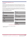
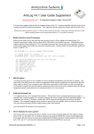
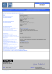
7. TAPE and REEL SPECIFICATIONS
P
1.5
4.00
+0.1
-0.0
2.00–0.10
Ko
x
T
1.75
14.20–0.10
28.40 Bo
W
x
Ao
2.00 Min
Section ’X-X’
DIMENSIONS
Ao
16.70 –0.10
Bo
21.80 –0.10
Ko
3.80 –0.10
P
24.00 –0.10
T
0.35 –0.05
W
32.00 –0.30
NOTES:
ALL DIMENSIONS IN MILLIMETERS
10 SPROCKET HOLE PITCH CUMULATIVE TOLERANCE – 0.20
MATERIAL: CONDUCTIVE POLYSTYRENE
CAMBER NOT TO EXCEED 1.0mm IN 250mm
Figure 4: Tape & Reel Specifications
NS34-DS MS20 Data Sheet Rev P03
Copyright ©2011 NavSync Ltd. All Rights Reserved
Date: 01/20/11
Specifications subject to change without notice.
23
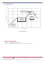
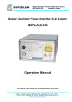
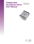
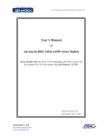
8. SOLDER PROFILE
300
Peak Temp.
245°-255°C for 15 sec Typ.
250
221°C
Temp (°C)
200
Reflow Zone
30/90 sec
(Min/Max)
150
Soaking Zone
60-90 sec Typ.
(2 min Max)
100
50
Ramp Slope not
to exceed
±3°C/sec
0
0
50
100
150
200
250
300
350
Time (sec)
Figure 5: Solder Profile
9. ORDERING INFORMATION
MS20
Standard Build, SBAS not supported.
Note: MSL3 per 1PC/JEDEC, J-STD-020C, J-STD-033B. Please use appropriate processing and handling techniques.
24
NS34-DS MS20 Data Sheet
Copyright ©2011 NavSync Ltd. All Rights Reserved
Rev P03
Date: 01/20/11
Specifications subject to change without notice.
10. APPENDICES
Appendix 1
//****************************************************************************
//
// Simple NMEA Checksum Tool - Copyright (C) 2007-2010 C Turvey, Navsync Ltd.
//
// Open Source - Licence Free - All Rights Reserved
//
// MSVC
cl -Ox nmeasum.c
//
//****************************************************************************
#include <windows.h>
#include <stdio.h>
#include <stdlib.h>
//****************************************************************************
//
// Win32 Console Application
//
// Compile with MSVC command line cl -Ox NMEASUM.c
//
// A NMEA command can be processed as a single argument, they do not contain spaces, and
// you do not need to provide the initial $ or trailing checksum, for example
//
//
NMEASUM PRTHS,U1OP,ALL=0,GSA=1,RMC=1
//
//
$PRTHS,U1OP,ALL=0,GSA=1,RMC=1*73
//
//
NMEASUM PNMRX111,COLD PNMRX111,HOT PNMRX600,INFO
//
//
$PNMRX111,COLD*40
//
$PNMRX111,HOT*17
//
$PNMRX600,INFO*4D
//
//****************************************************************************
static const char Hex[] = “0123456789ABCDEF”;
//****************************************************************************
NS34-DS MS20 Data Sheet Rev P03
Copyright ©2011 NavSync Ltd. All Rights Reserved
Date: 01/20/11
Specifications subject to change without notice.
25
10. APPENDICES continued
Appendix 1 continued
void NMEAMessage(unsigned char *s)
{
int i;
int j;
int Len;
BYTE Checksum;
BYTE Buffer[300];
Len = strlen(s);
j = 0;
Buffer[j++] = ‘$’; // Add Initial $
Checksum = 0; // Zero checksum
for(i=0; i<Len; i++) // Compute XOR checksum across body
{
Checksum ^= (unsigned char)s[i];
Buffer[j++] = s[i];
}
Buffer[j++] = Hex[(Checksum >> 4) & 0x0F]; // Add hexidecimal checksum
Buffer[j++] = Hex[(Checksum >> 0) & 0x0F];
Buffer[j++] = ‘\r’; // Add CR, LF
Buffer[j++] = ‘\n’;
Buffer[j++] = ‘*’; // Add * termination
Buffer[j++] = 0;
puts(Buffer);
}
//****************************************************************************
int main(int argc, char **argv)
{
int i;
for(i=1; i<argc; i++) // Process each argument as a NMEA sentence
NMEAMessage(argv[i]);
return(0);
}
//****************************************************************************
26
NS34-DS MS20 Data Sheet
Copyright ©2011 NavSync Ltd. All Rights Reserved
Rev P03
Date: 01/20/11
Specifications subject to change without notice.
10. APPENDICES continued
Appendix 2
//****************************************************************************
//
// Simple NMEA Parsing Tool - Copyright (C) 2007-2010 C Turvey, Navsync Ltd.
//
// Open Source - Licence Free - All Rights Reserved
//
// MSVC
cl -Ox parse.c
//****************************************************************************
#include <windows.h>
#include <stdio.h>
#include <stdlib.h>
#include <math.h>
//****************************************************************************
// Win32 Console Application
//
// Compile with MSVC command line cl -Ox PARSE.c
//
//
PARSE $GPGLL,4157.209646,N,08844.518354,W,153731.845,A,A*46
//
//
DecodeNMEA
//
$GPGLL,4157.209646,N,08844.518354,W,153731.845,A,A*46
//
Fields 08
//
#00 : $GPGLL
//
#01 : 4157.209646
//
#02 : N
//
#03 : 08844.518354
//
#04 : W
//
#05 : 153731.845
//
#06 : A
//
#07 : A
//
41 57.209646 -88 44.518354 [+41.9534941000 -88.7419725667] @ 15:37:31.845
//
//****************************************************************************
int Verbose = 1;
//****************************************************************************
// This code is provided for demonstational purposes, additional
// coding and testing would be required for more general use.
//
//****************************************************************************
// Parse $xxxxx,xx,..,xx*xx format sentences
NS34-DS MS20 Data Sheet Rev P03
Copyright ©2011 NavSync Ltd. All Rights Reserved
Date: 01/20/11
Specifications subject to change without notice.
27
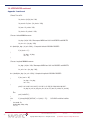
10. APPENDICES continued
Appendix 2 continued
#define FIELD_MAX 100
void DecodeNMEA(char *s)
{
char *field[FIELD_MAX];
int f;
int i;
char c;
int x;
if (Verbose)
{
puts(“DecodeNMEA”);
printf(“%s\n”,s);
}
// Check the line synchronization
if (s[0] != ‘$’)
return;
// Verify the line checksum integrity
c = 0;
// checksum
i = 1; // Xor bytes between $ and *, but not including those bytes
while((s[i] != 0) && (s[i] != ‘*’))
c ^= s[i++];
if (s[i] == 0)
return;
sscanf(&s[i + 1],”%x”,&x); // Checksum byte - Note sscanf needs this to be an int, rather than a single byte
if (c != (char)(x & 0xFF))
// Leave if checksum fails
return;
// Parse out fields on , and *
f = 0;
while(1)
{
28
NS34-DS MS20 Data Sheet
Copyright ©2011 NavSync Ltd. All Rights Reserved
Rev P03
Date: 01/20/11
Specifications subject to change without notice.
10. APPENDICES continued
Appendix 2 continued
field[f++] = s;
while((*s != 0) && (*s != ‘,’) && (*s != ‘*’) && (*s != 0x0D) && (*s != 0x0A))
s++;
if ((*s == 0) || (*s == ‘*’) || (*s == 0x0D) || (*s == 0x0A) || (f == (FIELD_MAX - 1)))
{
*s = 0;
field[f] = NULL;
break;
}
*s++ = 0;
}
if (Verbose)
{
printf(“Fields %02d\n”,f);
for(i=0; i<f; i++)
printf(“#%02d : %s\n”,i,field[i]);
}
// Process a couple of NMEA sentences for illustration
if ((strcmp(field[0],”$GPGLL”) == 0) && (f > 6)) // Geographic Position, Latitude, Longitude and Time
{
double lat, lon;
int lat_deg, lon_deg;
double lat_min, lon_min;
double fix_time;
int fix_hour, fix_minute;
double fix_second;
char lat_hemi, lon_hemi, valid;
// Field
// Field
// Field
// Field
// Field
// Field
// Field
1 Latitude DDMM.mmmmmm
2 Lat Hemi N/S
3 Longitude DDMMM.mmmmm
4 Lon Hemi E/W
5 UTC Time HHMMSS.SSS
6 Fix A=Valid, V=Not Valid
7 Mode A=Autonomous, D=Differential, E=Estimated, N=Not Valid [Optional] - Simulator Does not report this
sscanf(field[1],”%lf”,&lat);
lat_hemi = field[2][0];
sscanf(field[3],”%lf”,&lon);
lon_hemi = field[4][0];
sscanf(field[5],”%lf”,&fix_time);
valid = field[6][0];
if (valid == ‘A’)
{
NS34-DS MS20 Data Sheet Rev P03
Copyright ©2011 NavSync Ltd. All Rights Reserved
Date: 01/20/11
Specifications subject to change without notice.
29
10. APPENDICES continued
Appendix 2 continued
// Extract Time-of-Fix
fix_minute = (int)fix_time / 100;
fix_second = fix_time - (fix_minute * 100);
fix_hour = fix_minute / 100;
fix_minute = fix_minute % 100;
// Process Latitude DDMM.mmmmm
lat_deg = (int)lat / 100; // Decompose NMEA form ASCII into DEGREES and MINUTES
lat_min = lat - (lat_deg * 100);
lat = (double)lat_deg + (lat_min / 60.0); // Computed Latitude in DECIMAL DEGREES
if (lat_hemi == ‘S’)
{
lat_deg = -lat_deg;
lat = -lat;
}
// Process Longitude DDDMM.mmmmm
lon_deg = (int)lon / 100; // Decompose NMEA form ASCII into DEGREES and MINUTES
lon_min = lon - (lon_deg * 100);
lon = (double)lon_deg + (lon_min / 60.0); // Computed Longitude in DECIMAL DEGREES
if (lon_hemi == ‘W’)
{
lon_deg = -lon_deg;
lon = -lon;
}
printf(“%4d %9.6lf %4d %9.6lf [%+14.10lf %+14.10lf] @ %02d:%02d:%06.3lf\n”,
lat_deg, lat_min, lon_deg, lon_min, lat, lon, fix_hour, fix_minute, fix_second );
}
else
puts(“Invalid Fix”);
}
else if ((strcmp(field[0],”$GPGSA”) == 0) && (f > 17))
{
char mode, fix;
double pdop, hdop, vdop;
int i, sv;
30
// GPS DOP and Active Satellites
NS34-DS MS20 Data Sheet
Copyright ©2011 NavSync Ltd. All Rights Reserved
Rev P03
Date: 01/20/11
Specifications subject to change without notice.
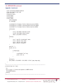
10. APPENDICES continued
Appendix 2 continued
// Field 1 A=Automatic(3D/2D), M=Manual
// Field 2 Fix 1=No Fix, 2=2D, 3=3D
// Field 3 SV List#1
// Field 14 SV List#12
// Field 15 PDOP
// Field 16 HDOP
// Field 17 VDOP
mode = field[1][0];
fix = field[2][0];
sscanf(field[15],”%lf”,&pdop); // Position Dilution of precision (PDOP)
sscanf(field[16],”%lf”,&hdop); // Horizontal Dilution of precision (HDOP)
sscanf(field[17],”%lf”,&vdop); // Vertical Dilution of precision (VDOP)
switch(mode)
{
case ‘A’ : puts(“Mode : Automatic”); break;
case ‘M’ : puts(“Mode : Manual”); break;
default : puts(“Mode : Unknown”);
}
switch(fix)
{
case ‘1’ : puts(“Fix : Not Available”); break;
case ‘2’ : puts(“Fix : 2D”); break;
case ‘3’ : puts(“Fix : 3D”); break;
default : puts(“Fix : Unknown”);
}
printf(“SV :”);
for(i=0; i<12; i++)
{
if (field[3+i][0])
{
sscanf(field[3+i],”%d”,&sv);
}
}
printf(“ %3d”, sv);
putchar(‘\n’);
printf(“PDOP : %5.2lf, HDOP : %5.2lf, VDOP : %5.2lf\n”, pdop, hdop, vdop);
}
}
//****************************************************************************
int main(int argc, char **argv)
{
int i;
for(i=1; i<argc; i++) // Process each argument as a NMEA sentence
DecodeNMEA(argv[i]);
return(0);
}
//****************************************************************************
NS34-DS MS20 Data Sheet Rev P03
Copyright ©2011 NavSync Ltd. All Rights Reserved
Date: 01/20/11
Specifications subject to change without notice.
31
MS20 GPS Receiver
User Manual
Revision
Revision Date
Notes
P00
P01
P03
05/18/10
08/19/10
01/20/11
User Manual Preliminary Release
Oscillator Update
Signal Description Updates
NavSync, Ltd. Europe
Bay 143
Shannon Industrial Estate
Shannon, Co. Clare, Ireland
Phone: +353 61 475 666
E-mail: [email protected]
North America
2111 Comprehensive Drive
Aurora, IL 60505, USA
Phone: 630.236.3026
E-mail: [email protected]
www.navsync.com