Download SECTION 2 INSTALLATION - Sea
Transcript
SECTION 2
INSTALLATION
________________________________________________________
2.7 HSL-WI5 SET-UP
The HSL-WI5 is shipped from the factory with the PLC program
“HSLWI5” loaded in the PLC section of the HSL-WI5 module and
the PLS channel set-point file “WI5TMG” loaded in the PLS section.
In most cases, the following user variables and timing channels may
have to be altered to tune the HSL-WI5 to the actual bodymaker it is
controlling.
Once the HSL-WI5 is installed and the control system is powered
back up, perform the following to set-up and tune the HSL-WI5. The
set-up is performed using the Display/Keypad or a PC running the
“HSLWI5” set-up program. See section 3 for a description of the
Keypad commands and menu displays of the HSL-WI5 Keypad/
Display. See section 4 for a description of the menus, variables and
how to use set-up program.
________________________________________________________
2.7.1 DEFAULT SET-UP VARIABLES
As shipped, the set-up variables for the M4500 main processor are set
to the following defaults:
Brake Wear Compensation:
Enabled
Desired BDC Stop Position (cont./single)
: Y
: 000°
Maximum Allowed Stopping Response
: 350°
Bodymaker Running Speeds:
Low Speed (SPM)
High Speed (SPM)
: 175
: 350
Number of Cupfeed Open/Initial Air Strip Strokes:
Number of Strokes Before Cupfeed Open
Number of Cans Made with Initial Air Strip
: 2
: 20
Trimmer Speed Reference:
Maximum Speed
Idle Speed (W/I stopped)
: 375
: 250
HSL-WI5 User’s Manual
SYSTEMS Electronics Group
- 19 -
SECTION 2
INSTALLATION
The “WI5TMG” timing channel file, as shipped, contains the
following default timing set points:
CHAN
ON - OFF
DESCRIPTION
CH00:
CH01:
CH02:
CH03:
CH04:
CH05:
CH06:
CH07:
150 – 170
200 – 220
155 – 175
110 – 130
150 – 350
150 – 200
120 – 190
180 – 000
BDC (Cont./Sing) timing
BDC (Inch) timing
Short Can Check timing
Sensor Check timing
Cupfeed timing
Air strip (Normal) timing
Air strip (Initial) timing
PLC Clock Timing
________________________________________________________
2.7.2 VERIFY MAIN CRANK RESOLVER
Using the Keypad/Display, press the “Set-up” key and select option 3
“Set Machine Timing” (see section 3.4.3). Verify that the main crank
resolver direction is correct and linear by barring or inching the
machine forward. The position (POS) should increment linearly
through the range of 0 to 359. If the direction is backwards, reverse
the S1 and S3 leads where the resolver cable connects to the M4500.
If the position is not linear (increments up then down or does not
increment through full range), verify that the resolver leads are all
connected and connected correctly. Refer to the electrical control
schematics at the back of the manual for wiring details.
HSL-WI5 User’s Manual
SYSTEMS Electronics Group
- 20 -
SECTION 2
INSTALLATION
________________________________________________________
2.7.3 SET BODYMAKER SET-UP PARAMETERS
The Bodymaker set-up parameters include:
1) Enabling or Disabling the Brake Wear Compensation
2) Setting the Desired Stopping Points (if the brake wear
compensation is enabled)
3) Setting the Maximum Allowed Stopping Response
4) Setting the Bodymaker Running Low and High Speeds
5) Setting the Number of Strokes before the Cupfeed Opens and
Number of Cans Made With Initial “Air Strip”
Brake Wear Compensation: If the brake wear compensation is to
be used, enable it by setting the “Brake Wear Compensation
Enable” to “Y” and set the “Desired BDC Stop Position
(cont./single)”. The desired BDC stop position is the desired
location of the ram when it comes to rest after a BDC stop. The
desired stopping position is generally set to 000 degrees. Enabling
the brake wear compensation allows the M4500 to automatically
adjust the BDC timing channel (CH00-Cont./Single) as necessary
such that the press will stop at the desired stopping position
regardless of the actual brake response.
If the brake wear compensation is not to be used, disable it by
setting the “Brake Wear Compensation Enable” to “N”. Disabling
the brake wear compensation requires the BDC timing (CH00)
signal to be set manually such that the press stops at BDC.
Note: If the brake response then changes, the press will not stop
at the desired position if the brake wear compensation is disabled.
Maximum Allowed Stopping Response: This parameter defines
the maximum allowed brake response before the “Brake Response
Too Long” alarm is generated. If the actual brake response
(number of degrees from when the brake is activated to the
position where the press ends up at rest) when a BDC stop is
performed is longer than this number, the alarm is generated. If
the actual brake response is less, the alarm is not generated. Set
this parameter to the value where the brake response is considered
too long and service to the brake should be performed (typically
270 to 350 degrees).
HSL-WI5 User’s Manual
SYSTEMS Electronics Group
- 21 -
SECTION 2
INSTALLATION
Bodymaker Running Speeds: Set the Bodymaker running “Low
Speed” and “High Speed” to the speeds that the bodymaker will
actually run at when the respective speed is selected.
Note: This is not a speed reference that will make the bodymaker
run at the speeds entered but is instead simply parameters used by
the M4500 to know when to switch between the “High” and
“Low” speed settings.
Number of Strokes before Cupfeed Open: This is the number
of strokes (plus 2) that the machine will make with air strip once
the cupfeed is enabled, before it actually opens. This allows
coolant to be blown from the ram to prevent “Hydraulic Lock”
(normally set to 2).
Number of Cans made with Initial Air Strip: This is the
number of cans made using the CH06 – “Initial Air Strip” timing
channel when the cupfeed is first opened before switching to
CH05 – “Normal Air Strip”. This allows the first cans to made
with more “Air Strip” while the tooling is cool.
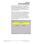
See section 3 “Using the Keypad/Display” or section 4 “HSLWI5 Setup Program Reference” for details on setting the above set-up
parameters.
HSL-WI5 User’s Manual
SYSTEMS Electronics Group
- 22 -
SECTION 2
INSTALLATION
________________________________________________________
2.7.4 SET TRIMMER SPEED REFERENCES
Set both the “Trimmer Maximum Speed” and “Trimmer Idle Speed”
as desired. These two parameters are used to control the speed
reference (0-10VDC) to the trimmer.
Trimmer Maximum Speed: The “Trimmer Maximum Speed”
parameter is used to scale the 0-10VDC analog output such that
when the bodymaker is running at the speed entered in “Trimmer
Maximum Speed”, the analog output will be at 10 volts.
Trimmer Idle (Minimum) Speed: This parameter determines the
speed the trimmer will run at when the bodymaker is stopped (declutched).
Note: When the bodymaker is running, the trimmer speed reference
is proportional (as set by the “Trimmer Maximum Speed” scaling) to
the speed of the bodymaker. This parameter is used to provide the
speed reference when the bodymaker speed is zero.
See section 3 “Using the Keypad/Display” or section 4 “HSLWI5 Setup Program Reference” for details on setting the above set-up
parameters.
________________________________________________________
2.7.5 SET MACHINE ZERO
Inch the main crank of the bodymaker to back dead center (BDC) and
set the M4500 offset using the D4591 Keypad/Display.
1) Press the “Set-up” key and select option 4 “Zero Machine (set
resolver offset)”, see section 3.4.4.
2) Enter “0” to set the resolver offset. The timing set-up menu will
then be displayed, showing the “POS:” at zero. The M4500
calculates the actual offset value required to make this the zero
position and displays this number in the offset field.
3) Return to the primary set-up menu by pressing <ESC>. Return to
the default screen by pressing <ESC> again.
HSL-WI5 User’s Manual
SYSTEMS Electronics Group
- 23 -
SECTION 2
INSTALLATION
________________________________________________________
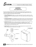
2.7.6 VERIFY LOCATION OF SHORT CAN TIMING (CH02)
Inch the machine and verify that the “Short Can” timing (CH02) of
the M4500 first turns ON when the short can sensor is over the nose
of the punch on the forward portion of the stroke. This would be
where the sensor would first “see” the can as it emerges from the die
set. Verify that the “Short Can” timing turns “off” right before the
sensor would quit seeing the lip of the can as the ram continues it's
forward motion. Adjust either or both of the ON or off locations of
CH02 until the above is achieved. Depending on the location of the
short can sensor, CH02 is typically set ON at 155 degrees and off at
175 degrees.
________________________________________________________________________________
Figure 2 – Short Can Check Timing Sequence
HSL-WI5 User’s Manual
SYSTEMS Electronics Group
- 24 -
SECTION 2
INSTALLATION
Note: The short can sensor must “see” can the entire time the “Short
Can” timing (CH02) is ON in order to pass the short can check,
otherwise the “Short Can” alarm will be generated.
Verify that the “Sensor Check” timing (CH03) is set correctly. This
timing signal should go ON for 20 degrees then off prior to the punch
emerging from the die set (typically 110 to 130 degrees). This signal
is used to verify that the short can sensor has not failed ON and
therefore the short can sensor must be off the entire time CH03 is ON
otherwise the “Die Sensor Fail” alarm is generated.
See section 3 “Using the Keypad/Display” or section 4 “HSLWI5 Setup Program Reference” for details on setting CH02 and CH03.
________________________________________________________
2.7.7 VERIFY SINGLE CUPFEED
With the machine running in continuous mode and the “Cupfeed Auto
Enable” off, feed a single cup through the machine by depressing the
“Cupfeed ON Manual” push-button. The cupfeed solenoid should
open for one cup and activate the air strip for three strokes prior to the
can being punched (can punched on fourth stroke). Verify the cupfeed
timing (CH04), air strip timing (CH05 and CH06), and short can
timing (CH02). Adjust as necessary to achieve smooth cupfeed
operation with no false short can shut downs.
HSL-WI5 User’s Manual
SYSTEMS Electronics Group
- 25 -
SECTION 2
INSTALLATION
________________________________________________________
2.7.8 VERIFY MACHINE OPERATION
Run the machine in normal production.
Verify Air Strip Timing: With the machine running and the cupfeed
open, adjust the respective “Air Strip” timing (CH05-Normal,
CH06-Initial) and verify that the cans are stripped without any
problems. See section 3 “Using the Keypad/Display” or section 4
“HSLWI5 Set-up Program Reference” for details on adjusting
CH05 and CH06.
Verify Short Can Timing: With the machine running and the
cupfeed open, verify that no false short can faults are occurring
(short can alarm occurs when full length can is made). If a false
short can alarm are occurs, narrow the short can timing window
one degree at a time until false short can alarms are no longer
generated.
Verify that the short can detection is working correctly by
generating a short can and verifying that the short can alarm is
generated. This can be done by stopping the press, removing one
of the die rings, then punching a cup in single stroke mode. The
short can alarm should be generated when the cup is punched.
Verify BDC Stop: If the brake wear compensation is enabled, verify
that the press does stop at the desired location.
Note: When the system is first installed, it will take a few
successive stops for the algorithm to program the BDC timing
channel to the correct position. The compensation is enabled after
the press has been running at a fixed speed in continuous. The
BDC timing channel will not be modified when single strokes are
made or if press is started in continuous and then immediately
stopped again. Wait about 5 seconds after the press is started
before performing the BDC stop to verify the stop position.
If the brake wear compensation is disabled, manually adjust both
the BDC (Cont./Single) timing (CH00) and the BDC (Inch) timing
(CH01) such that the press stops at back dead center at both
respective speeds. See section 3 “Using the Keypad/Display” or
section 4 “HSLWI5 Set-up Program Reference” for details on
adjusting CH00 and CH01.
HSL-WI5 User’s Manual
SYSTEMS Electronics Group
- 26 -
SECTION 2
INSTALLATION
Verify BDC Stop Sequence: Perform a normal manual BDC stop
while the cupfeed is open and verify that the cupfeed closes. The
machine should make two extra strokes processing the two
remaining cups in the cupfeed cam and stop at BDC with no cups
in the cup locator or cupfeed cam. This sequence should be true
for standby stops and BDC alarm stops as well.
The Machine is Now Set-Up and Ready to Run!
HSL-WI5 User’s Manual
SYSTEMS Electronics Group
- 27 -


