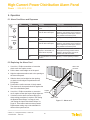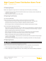
1
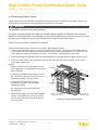
High-Current Power Distribution Alarm Panel
Power :: 009-6212-2100
User Manual
Applys to : 009-6212-2100
© Telect, Inc., All Rights Reserved, 117926-5 A0
1.509.926.6000 :: telect.com
High-Current Power Distribution Alarm Panel
Power :: 009-6212-2100
Table of Contents
1. System Description�����������������������������������������������������������������������������������������������������������1
1.1 General Description��������������������������������������������������������������������������������������������������������1
1.2 Electrical Specifications��������������������������������������������������������������������������������������������������1
1.3 Mechanical Specifications����������������������������������������������������������������������������������������������2
1.4 Physical Attributes����������������������������������������������������������������������������������������������������������3
1.5 Schematic diagram���������������������������������������������������������������������������������������������������������4
2. Before You Begin��������������������������������������������������������������������������������������������������������������5
2.1 Document Authority�������������������������������������������������������������������������������������������������������5
2.2 Tools�������������������������������������������������������������������������������������������������������������������������������5
2.3 Cables and Cabling Hardware����������������������������������������������������������������������������������������5
2.4 Safety Warnings��������������������������������������������������������������������������������������������������������������6
2.4.1 Clothing and Work Environment����������������������������������������������������������������������������� 6
2.4.2 Electrical Safety������������������������������������������������������������������������������������������������������6
2.4.3 In Case of Accident�������������������������������������������������������������������������������������������������6
3. Rack-Mounting������������������������������������������������������������������������������������������������������������������7
3.1 Planning Rack Location and Space�������������������������������������������������������������������������������� 7
3.2 Rack-Mounting and Labeling Procedure������������������������������������������������������������������������ 7
4. Connecting Cables�����������������������������������������������������������������������������������������������������������9
4.1 Cabling Guidelines����������������������������������������������������������������������������������������������������������9
4.2 Cable Conventions���������������������������������������������������������������������������������������������������������9
4.2.1 Polarity��������������������������������������������������������������������������������������������������������������������9
5. Installing Breakers����������������������������������������������������������������������������������������������������������10
5.1 General Guidelines for Installing Breakers������������������������������������������������������������������� 10
5.2 HCPDAP Circuit Breaker Capapcity����������������������������������������������������������������������������� 10
4.2.2 Color Conventions������������������������������������������������������������������������������������������������ 11
4.3 Power System Diagram������������������������������������������������������������������������������������������������ 11
4.4 Connecting Ground Cables������������������������������������������������������������������������������������������12
4.5 Connecting Input Power Cables�����������������������������������������������������������������������������������12
4.6 Connecting to the Power Bays�������������������������������������������������������������������������������������13
4.7 Supplying and Testing Input Power������������������������������������������������������������������������������ 14
4.8 Testing the Input Power Alarms Relays������������������������������������������������������������������������ 15
4.9 Connecting Output Cables��������������������������������������������������������������������������������������������16
5. Installing Breakers����������������������������������������������������������������������������������������������������������19
5.1 General Guidlines for Installing Breakers��������������������������������������������������������������������� 19
5.2 HCPDAP Circuit Breaker Capacity�������������������������������������������������������������������������������19
5.3 Calculating Circuit Breaker Ratings������������������������������������������������������������������������������ 20
5.4 Installing Circuit Breakers���������������������������������������������������������������������������������������������20
5.5 Testing HCPDAP Output Circuit Polarity���������������������������������������������������������������������� 21
5.6 Testing the Breaker Alarm Relays���������������������������������������������������������������������������������21
5.6.1 Breaker Alarm Relay Test��������������������������������������������������������������������������������������22
5.6.2. Breaker Alarm Visual Indicator Test��������������������������������������������������������������������� 22
5.7 Connecting and Testing External Alarms���������������������������������������������������������������������� 23
5.8 Labeling the Distribution Panel�������������������������������������������������������������������������������������24
5.9 Powering the Load Equipment��������������������������������������������������������������������������������������24
© Telect, Inc., All Rights Reserved, 117926-5 A0
1.509.926.6000 :: telect.com
ii
High-Current Power Distribution Alarm Panel
Power :: 009-6212-2100
6. Operation������������������������������������������������������������������������������������������������������������������������25
6.1 Alarm Conditions and Reponses���������������������������������������������������������������������������������� 25
6.2 Replacing the Alarm Card���������������������������������������������������������������������������������������������25
6.3 Resetting Breakers�������������������������������������������������������������������������������������������������������26
6.4 Replacing Circuit Breakers�������������������������������������������������������������������������������������������26
6.4.1 Power Considerations�������������������������������������������������������������������������������������������26
6.4.2 Circuit Breaker Replacement Guidelines�������������������������������������������������������������� 26
6.5 Replacing Breakers������������������������������������������������������������������������������������������������������26
7. Service����������������������������������������������������������������������������������������������������������������������������29
7.1 Owner Maintenance������������������������������������������������������������������������������������������������������29
7.2 In-Warranty Service������������������������������������������������������������������������������������������������������29
7.3 Out-of-Warranty Service�����������������������������������������������������������������������������������������������29
7.4 Repacking for Shipment�����������������������������������������������������������������������������������������������29
8. Accessories���������������������������������������������������������������������������������������������������������������������30
List of Figures
Figure 1 - Attributes and Dimensions������������������������������������������������������������������������������������ 3
Figure 2 - Schematic�������������������������������������������������������������������������������������������������������������4
Figure 3 - Mounting bracket��������������������������������������������������������������������������������������������������8
Figure 4 - Rack-mounting bracket����������������������������������������������������������������������������������������8
Figure 5 - Power System���������������������������������������������������������������������������������������������������� 11
Figure 6 - Input Power Hookup�������������������������������������������������������������������������������������������13
Figure 7 - Bus Bar Diagram������������������������������������������������������������������������������������������������14
Figure 8 - Test Input Polarity�����������������������������������������������������������������������������������������������14
Figure 9 - Test Power Alarm Relays�����������������������������������������������������������������������������������15
Figure 10 - Output Cable Hookup���������������������������������������������������������������������������������������16
Figure 11 - Installing the circuit breaker������������������������������������������������������������������������������ 20
Figure 12 - Securing the circuit breaker������������������������������������������������������������������������������ 21
Figure 13 - Test Equipment Polarity������������������������������������������������������������������������������������21
Figure 14 - Test Breaker Alarm Relays�������������������������������������������������������������������������������22
Figure 15 - Alarm leads�������������������������������������������������������������������������������������������������������23
Figure 16 - Breaker Designation Card��������������������������������������������������������������������������������24
Figure 17 - Alarm card��������������������������������������������������������������������������������������������������������25
Figure 18 - Installing the Circuit Breaker���������������������������������������������������������������������������� 27
© Telect, Inc., All Rights Reserved, 117926-5 A0
1.509.926.6000 :: telect.com
iii
High-Current Power Distribution Alarm Panel
Power :: 009-6212-2100
1. System Description
1.1 General Description
The Telect dual-feed High-Current Power Distribution Alarm Panel (HCPDAP, Model 009-6212-2100) accepts two
input power circuits of the same polarity up to 200 amps.
It distributes up to 200 amps load amperage per side (400 amps total). The distribution panel holds six “bullet
terminal” front-access circuit breakers per side (12 total). Each breaker position is capable of breakers rated up
to 100 amps.
Acceptable voltages are +20 to +30 VDC, or –20 to –60 VDC.
Features include:
• Dual-feed power inputs (Input A and Input B)
• Accepts circuit breakers rated up to 100 amps (see “Accessories” on Page 8-1)
• Breaker alarm with single visual and single remote dry contact indicator
• Visual A and B input power alarms with single remote dry contact indicator
• Replaceable alarm card
• Total rear access (TRA) for input and output power
• 009-6212-2100 is Listed by UL for USA and Canada
• 009-6212-2100 is NEBS and CE certified
1.2 Electrical Specifications
Electrical Specifications
Operating voltages
–20 to –60 VDC, +20 to +30 VDC
Maximum continuous input load rating
200A
Maximum input interruption device rating
250A
Maximum output interruption device rating
100A per circuit breaker
Maximum continuous output load rating
100A per circuit breaker
Alarm contact ratings, continuous
2A at 30 VDC 0.6A at 60 VDC 1A at 120 VAC
Alarm board power ratings (maximum power draw)
@20V: 32 mA (0.64 W)
@27V: 44 mA (1.19 W)
@42V: 54 mA (2.27 W)
@56V: 63 mA (3.53 W)
Max. operating temperature at max. load ratings
55° C (131° F)
Min. operating temperature at max. load ratings
–10° C (14° F)
Ambient operating temp. at half-load
Max. surface temperature of breakers at 26°C (79°F) ambient
Max. panel heat dissipation at full load
Percentage of full load heat dissipation
© Telect, Inc., All Rights Reserved, 117926-5 A0
1.509.926.6000 :: telect.com
@24V: 40 mA (0.96 W)
@30V: 46 mA (1.38 W)
@48V: 58 mA (2.78 W)
@60V: 66 mA (3.96 W)
60° C (140° F)
37° C (99° F)
20W per side at 9600W (200A x 48V) per side
Less than 0.5%
1
High-Current Power Distribution Alarm Panel
Power :: 009-6212-2100
1.3 Mechanical Specifications
Mechanical Specifications
Dimensions, with brackets
Weight, without breakers
Weight, shipping
Mounting capability:
(ETSI brackets sold separately)
Ground terminals
Input terminals
Output terminals
Alarm terminals
Width:
Height:
Depth:
19.065 lb (8.648 kg)
22 lb (10 kg)
EIA:
WECO:
ETSI:
19–inch (48.26 cm)
23–inch (58.42 cm)
Kits sold separately. See
“Accessories” on page 30).
Quantity:
Stud size:
Nut:
Socket size:
Cable:
2
1/4 inch
1/4–20 HEX
7/16 inch (12 mm)
Up to 1 AWG (depending on size of input
interruption device)
2-hole compression lug
Same as cable up to 1 AWG
5/8 inch
25 in-lb (2.83 N-m)
Lugs:
Size:
Center to center:
Maximum torque:
Quantity:
Stud size:
Nut:
Socket size:
Cable:
4: 2 BATT, 2 RTN
5/16 inch
5/16–18 KEPS
1/2 inch (13 mm)
#6 to 4/0 AWG (depending on size of
input interruption device)
2-hole compression lug
Same as cable up to 4/0 AWG; 1” width MAX.
1 inch
40 in-lb (4.52 N-m)
Lugs:
Size:
Center to center:
Maximum torque:
Quantity:
Stud size:
Nut:
Socket size:
Cable:
24: 12 BATT, 12 RTN
#10
#10–32 KEPS
3/8 inch (10 mm)
#6 to 2 AWG (depending on size of output
breaker)
2-hole compression lug
Same as cable up to 6 AWG; 0.6” width
5/8 inch
20 in-lb (2.27 N-m)
Lugs:
Size:
Center to center:
Maximum torque:
Quantity:
Stud size:
Cable:
© Telect, Inc., All Rights Reserved, 117926-5 A0
1.509.926.6000 :: telect.com
19.00 in. (48.26 cm)
4.97 in. (12.63 cm)
7.99 in. (20.31 cm)
6
#3–48
18–22 AWG
2
High-Current Power Distribution Alarm Panel
Power :: 009-6212-2100
1.4 Physical Attributes
Power alarm
indicator (Input A)
Alarm card
Cover plate
A
POWER
A
B
A
B
ALARM
POWER
B
6
5
4
3
1
2
1
MAX 100A BREAKER
MAX 200A CONFIGURATION
2
4
5
6
MAX 100A BREAKER
MAX 200A CONFIGURATION
SPOKANE, WA
800 551 4567
Captive screw
Breaker alarm indicator
3
Power alarm
indicator (Input B)
Mounting screw
Dimensions (L x W x D):
17.25 x 5 x 8 inches
[43.82 x 12.7 x 20.32 cm]
Lug width
0.60 [1.52]
B
BATT
Lug width
0.60 [1.52]
RTN
5/8
[1.59]
Breaker alarm and
power alarm relays
BATT
BATT
RTN
1
5/8
[1.59]
BATT
A
1
NO
C
NC
NC
C
NO
2
3
4
BREAKER
ALARM
2
POWER
FAIL
1.00
[2.54]
SPOKANE, W
A
3
4
800 551 4567
5
5
B INPUT 6
–48 — +24
200A
6
CHS CHS
GND GND
Earth-ground studs
Input power terminal
A INPUT
–48 — +24
200A
6
Output return
(RTN) terminal
Figure 1 - Attributes and Dimensions
© Telect, Inc., All Rights Reserved, 117926-5 A0
1.509.926.6000 :: telect.com
3
Output battery
(BATT) terminals
High-Current Power Distribution Alarm Panel
Power :: 009-6212-2100
1.5 Schematic diagram
A
BATT
INPUT
RTN
6
5
4
3
2
RTN
1
6
5
4
BATT
3
2
1
C GND
INPUT POWER A
GREEN
BREAKER ALARM
RED
POWER
ALARM
NO
C
NC
NC
C
NO
ALARM
CIRCUIT
INPUT POWER B
GREEN
BREAKER
FAIL
Note: Relays shown
in alarm condition
C GND
1
2
3
BATT
4
5
6
1
2
3
4
RTN
5
6
RTN
BATT
Figure 2 - Schematic
© Telect, Inc., All Rights Reserved, 117926-5 A0
1.509.926.6000 :: telect.com
4
B INPUT
High-Current Power Distribution Alarm Panel
Power :: 009-6212-2100
2. Before You Begin
2.1 Document Authority
Your operating company’s approved installation procedures take priority over this manual. Modify these
instructions accordingly.
This manual describes a best-practice method of DC distribution breaker panel installation and operation. It does
not attempt to specify a standard for engineering design and installation.
2.2 Tools
The following tools and terminals are needed to install this device:
• No. 1 and No. 2 Phillips head screwdrivers
• No. 2 flathead screwdriver
• 7/16–inch (12 mm), 1/2–inch (12 mm), and 3/8–inch (10 mm) torque wrenches or sockets
• Cable cutter and insulation stripping tool
• Approved wire-terminal crimping tools
• Lacing cord or nylon cable ties
• Voltmeter
• Ohmmeter
2.3 Cables and Cabling Hardware
The following cables and terminals are needed to install this device:
• Ground cable(s)
• 2 two-hole compression lugs for ground cable(s)
• Two BATT and two RTN input power cables
• 4 two-hole compression lugs for input power cables
• BATT and RTN output cables, as needed
• 2 two-hole compression lugs per output cables.
• 18 AWG to 26 AWG standard telecom hookup wire to connect remote alarms
© Telect, Inc., All Rights Reserved, 117926-5 A0
1.509.926.6000 :: telect.com
5
High-Current Power Distribution Alarm Panel
Power :: 009-6212-2100
2.4 Safety Warnings
2.4.1 Clothing and Work Environment
!
CAUTION
Do not work alone under potentially hazardous conditions.
Wear safety glasses. Do not wear loose clothing that may get caught in equipment. Roll up your sleeves,
and remove or fasten neckties and scarves. Remove jewelry such as rings, necklaces, and watches before
working on this equipment.
Eliminate potential hazards in your work area, such as wet floors, ungrounded power cables, cluttered
aisles, etc. Keep tools away from walkways, aisles, or places where people could trip over them. Provide
safety cones when saying equipment or cables on the floor.
Always secure loose cables to the cable racks.
2.4.2 Electrical Safety
!
WARNING
Only trained and qualified personnel should install, service, or replace this device.
Read all installation instructions before you connect this device to a power source.
Disconnect all power before you install or remove this device, or before you work near a power supply.
Never assume that circuit power is off-always verify.
This equipment must be grounded. Verify that it is connected to earth ground before applying power.
Never operate this equipment in the absence of an earth ground. Contact an authorized electrical inspection
authority or an electrician if you are uncertain that suitable grounding is available.
A readily accessible interruption device (breaker or fuse) must be incorporated in the fixed input wiring.
Do not work on the system or handle cables during periods of lightning activity.
Locate the emergency power-OFF switch in the room in which you are working in order to quickly shut
down power if an electrical accident occurs.
2.4.3 In Case of Accident
Should you witness an electrical accident, do the following:
1. Turn OFF power to the system.
2. When possible, stay with the victim and send another person to get medical assistance. Otherwise, determine
the condition of the victim, then call for help.
3. Determine if the victim needs CPR. If qualified, take appropriate action.
© Telect, Inc., All Rights Reserved, 117926-5 A0
1.509.926.6000 :: telect.com
6
High-Current Power Distribution Alarm Panel
Power :: 009-6212-2100
3. Rack-Mounting
3.1 Planning Rack Location and Space
The distribution panel’s mounting brackets provide mounting access to the following racks:
• 19–inch (48.26 cm) EIA racks
• 23–inch (58.42 cm) WECO racks.
Telect recommends the following mounting practices:
• Mount the panel to the upper-most rack position.
• Allow one rack unit of empty space (1.75 inches or 4.45 cm) below the panel to provide adequate ventilation.
3.2 Rack-Mounting and Labeling Procedure
!
WARNING
Do not supply power to the equipment rack or the distribution panel until the panel is securely mounted
and grounded.
Note that the distribution panel has three sets of mounting points—flush, three-inch offset, and four-inch offset.
The panel ships with brackets positioned for flush mounting to a 19” or 23” rack.
1. Decide if the distribution panel is to be mounted flush with the equipment rack, or if it is to be offset (extended)
from the rack.
2. If needed, move the mounting brackets to the desired position on the product’s chassis. Torque the screws to
25 in-lb (2.83 N•m).
3. Align the holes in the mounting brackets to the holes on the equipment rack. Then mount the distribution
panel to the equipment rack with the four mounting screws and star washers.
4. Torque the screws to 35 in-lb (4.29 N•m).
5. Label the front and the rear of the panel according to the labeling conventions specified in Telect 117995 Wire
Sizing and Labels.
See the illustration on the following page for rack-mounting procedure.
© Telect, Inc., All Rights Reserved, 117926-5 A0
1.509.926.6000 :: telect.com
7
High-Current Power Distribution Alarm Panel
Power :: 009-6212-2100
Distribution Panel
Chassis
Flush
Position
Mounting
Bracket
Offset
Position
#10 screw (116903)
25 in-lbs [2.83 N-m]
Figure 3 - Mounting bracket
Equipment
Rack
Torque Panhead screws
and star washers to
35 in-lbs [4.29 N-m]
Figure 4 - Rack-mounting bracket
© Telect, Inc., All Rights Reserved, 117926-5 A0
1.509.926.6000 :: telect.com
8
High-Current Power Distribution Alarm Panel
Power :: 009-6212-2100
4. Connecting Cables
4.1 Cabling Guidelines
NOTE: Cables and hook-up wires must conform to your operating company’s installation guidelines, as well as,
national, regional and local electrical codes.
Follow these guidelines when building cables:
• Account for the worst-case situation of your application when selecting materials for cable and hook-up
wire installations.
• Use properly rated cables and compression lugs approved by a nationally recognized test laboratory (NRTL)
for all power cables and ground cables.
• Crimp all terminals with tooling approved by the terminal’s manufacturer.
• Cover power cable compression lug barrels with UL94V0 rated heat shrink tube.
• Mark each cable end with its opposite termination destination and its polarity.
• Secure cables to the equipment rack to prevent loose, falling cables.
• At the BDFB and other equipment, attach power cables to the cable management system (CMS) with lacing
cord or nylon cable ties before terminating them.
• When installing power cables, do not strain or twist the cables. The cables must move smoothly and easily
into place.
• Install cables in a neat, uniform manner.
In most cases, your operating company’s installation procedures will provide you with the necessary guidelines
and wire charts necessary to determine the properly rated wires, cables, and compression lugs to perform this
installation. If this information is not provided, consult your engineer, or see Telect 117995 Wire Sizing and Labels.
4.2 Cable Conventions
4.2.1 Polarity
Use the following conventions when preparing cables:
Term:
Designation:
RTN
Return (RTN) refers to the plant polarity referenced to earth-ground.
BATT
Battery (BATT) refers to the power distribution source’s circuit-interrupt (fuse/breaker) polarity.
© Telect, Inc., All Rights Reserved, 117926-5 A0
1.509.926.6000 :: telect.com
9
High-Current Power Distribution Alarm Panel
Power :: 009-6212-2100
5. Installing Breakers
5.1 General Guidelines for Installing Breakers
Operating companies have guidelines to determine proper circuit breaker ratings. Telect recommends you follow
those guidelines where applicable.
Also follow the guidelines below when installing circuit breakers in the High Current Power Distribution Alarm
Panel (HCPDAP). These practices prevent injury to personnel, ensure proper distribution panel operation, and
prevent damage to the distribution panel and connected equipment.
• Install all output cabling and verify output cable polarities before permanently activating breakers.
• Always select a properly rated breaker for the circuit. Refer to your job specifications for maximum output load
ratings and corresponding circuit breaker ratings, or see “5.3 Calculating Circuit Breaker Ratings” on Page 5-2.
!
CAUTION
The maximum rated load current for each circuit breaker position must not exceed 100 amps.
The combined current for each output branch circuit (total A output or total B output) must not exceed 200
amps per side.
• Keep cover plates over all vacant breaker positions at all times during installation.
• Review the HCPDAP’s power requirements and corresponding cable gauges any time the you add or remove
equipment from the panel. This practice confirms proper breaker ratings for the modified circuits, and it ensures
that the panel load capacity is not exceeded.
• Read the installation guide provided with the circuit breaker.
• When using high-current breakers, try to leave at least one empty breaker position between breakers.
5.2 HCPDAP Circuit Breaker Capapcity
The HCPDAP maximum circuit breaker capacity is 200 amps per side (A and B) for a total of 400 amps. Do not
exceed a rating of 100 amps for any breaker position in the panel.
The sum of the circuit breaker ratings on either side (A or B) of the HCPDAP must not exceed that side’s
maximum rated input current.
Example:
If A and B input current is rated at 200 amps, then the sum of the panel’s circuit breaker ratings must be less than
or equal to 200 amps:
A–1 + A–2 + ... + A–6 ≤ 200 amps
B–1 + B–2 + ... + B–6 ≤ 200 amps
© Telect, Inc., All Rights Reserved, 117926-5 A0
1.509.926.6000 :: telect.com
10
High-Current Power Distribution Alarm Panel
Power :: 009-6212-2100
4.2.2 Color Conventions
When using colored cables, use the following color conventions:
Color:
Designation:
BLUE
Battery (BATT) polarity B
RED
Battery (BATT) polarity A
BLACK
Return (RTN)
GREEN
Earth-ground
4.3 Power System Diagram
AC MAINS
RECTIFIERS
BATTERIES
DC MAIN (A)
DC MAIN (B)
BATTERY DISTRIBUTION
FUSE/BREAKER BOARDS (BDFB)
BDFB
A
(Primary DC power
distribution sources)
INPUT A
HIGH CURRENT
POWER DISTRIBUTION
PANEL
INPUT B
EQUIPMENT
INPUT A
HIGH CURRENT
POWER DISTRIBUTION
PANEL
INPUT B
EQUIPMENT
Figure 5 - Power System
© Telect, Inc., All Rights Reserved, 117926-5 A0
1.509.926.6000 :: telect.com
11
BDFB
B
High-Current Power Distribution Alarm Panel
Power :: 009-6212-2100
4.4 Connecting Ground Cables
NOTE: The RTN and BATT terminals are completely isolated from the chassis ground. Earth-ground reference is
determined by plant polarity.
1. Determine the proper ground cable configuration by the BDFB output amperage that feeds the HCPDAP input
power terminals. Then, construct the ground cable(s). Use properly rated cables with two-hole compression
lugs. For assistance, refer to your operating company’s installation procedures, or see Telect 117995 Wire
Sizing and Labels.
2. Locate the earth-ground studs on the HCPDAP backplane (see drawing on next page).
3. Recommended: For improved surface contact, remove the paint from the HCPDAP chassis that surrounds the
earth-ground studs. Use appropriate paint removing tools, such as a wire brush or a Dremel® tool.
4. Clean the contact areas of the compression lugs and the mating surface of the HCPDAP chassis. Use a
coarse non-metallic cleaning pad.
5. Secure the compression lug to the grounding studs with the 1/4–20 HEX nuts provided. Torque the nuts to 25
in-lb (2.84 N•m) with a 7/16–inch (12 mm) socket.
NOTE: If required by the operating company’s installation procedures, use anti-oxidant compound between the
cable compression lugs and the corresponding grounding surfaces, such as the chassis, equipment rack, ground
relay rack, or ground bus.
6. Attach the ground cable(s) to the ground relay rack or ground bus according to the operating company’s
installation procedures.
4.5 Connecting Input Power Cables
Input power cables connect the HCPDAP to the BDFB. The cables must support 125% of the rated continuous
load current of the equipment powered by the HCPDAP breakers, up to 200 amps per side.
!
WARNING
Before connecting input power cables, shut down BDFB Power to the circuits feeding the HCPDAP.
Remove or lock out the BDFB circuit breakers, or verify that the BDFB fuse positions are open.
1. Construct BATT and RTN cables for both A and B input power circuits. Use properly rated cables and twohole compression lugs. Insulate the lug barrels with UL 94V-0 rated heat shrink tubing.
For assistance, refer to the operating company’s installation procedures, or see Telect 117995 Wire Sizing
and Labels.
© Telect, Inc., All Rights Reserved, 117926-5 A0
1.509.926.6000 :: telect.com
12
High-Current Power Distribution Alarm Panel
Power :: 009-6212-2100
INPUT POWER HOOKUP
2. Locate the two input power terminals (Input A and
Input B) on the HCDPAP backplane. Remove the
black plastic terminal covers.
3. Clean the contact areas of the compression lugs
and the input power terminal. Use a coarse
non-metallic cleaning pad.
Input power
terminal block
Heat shrink
tubing
BATT
RTN
Note: Clean all
contact surfaces
NOTE: If required by the operating company’s
installation procedures, use anti-oxidant compound
between the cable compression lugs and the input BATT
and RTN terminals.
4. Secure the BATT and RTN cables to the input
power terminal blocks with the 5/16–18 KEPS nuts,
as shown. Torque the nuts to 40 in-lb (4.52 N•m)
with a 1/2–inch (13 mm) socket.
A INPUT
MAX INPUT LOAD 200 AMP
Torque 5/16
to 40 in-lb [4.52 N-m]
–18 KEPS nuts
5. Reinstall the terminal block covers.
4.6 Connecting to the Power Bays
!
Compression
lug
Figure 6 - Input Power Hookup
WARNING
Use extreme caution! The DC power circuits surrounding the cable termination points are live!
Refer to the operating company’s installation procedures for connections to power bays. You may be
required to have power personnel on site when making these connections.
The power bays come in two basic configurations:
• The fuse/breaker battery (BATT) terminations and the return (RTN) bus are contained within the same bay.
• The fuse/breaker battery (BATT) terminations are contained within the bay, but the return (RTN) bus is located
outside the bay
NOTE: The 48 VDC BDFB must be electrically isolated from the AC power source, and must be reliably connected
to earth-ground.
1. Before making cable connections, remove the BDFB fuse/breaker for this circuit, and remove any signal
indicator fuses, when present.
2. Use a DC voltmeter to verify that no voltage is present at the BDFB output terminals.
3. Clean the contact areas of the cable compression lugs and the power bay output terminals. Use a coarse
non-metallic cleaning pad.
4. Carefully secure the BATT cables to the BDFB output terminals in a neat, uniform manner, according to the
operating company’s installation procedures. Provide only one BATT cable termination per fuse/breaker
position. Do not combine separate loads on the same fuse/breaker.
NOTES:
• If required by the operating company’s installation procedures, use anti-oxidant compound between the cable
compression lugs and the BDFB output BATT and RTN terminals.
• Do not connect the returns to any bus bars marked for CO grounds.
© Telect, Inc., All Rights Reserved, 117926-5 A0
1.509.926.6000 :: telect.com
13
High-Current Power Distribution Alarm Panel
Power :: 009-6212-2100
5. Carefully secure the RTN cables to the BDFB return bus in a neat, uniform manner, according to the operating
company’s installation procedures.
For two-cable arrangements, it is normally acceptable to connect the A and B return (RTN) cable lugs to the
return bus bar in a back-to-back arrangement so that they sandwich the bus bar, as shown.
Figure 7 - Bus Bar Diagram
4.7 Supplying and Testing Input Power
!
WARNING
DO NOT SUPPLY POWER to the HCPDAP until it is securely mounted and grounded!
Before supplying input power, verify that the HCPDAP has no circuit breakers installed! This measure
prevents power from reaching any output path.
1. At the BDFB fuse/breaker board, insert the properly
rated fuse or breaker for the circuit that feeds the
HCPDAP.
BATT
NOTE: The maximum allowable fuse or breaker rating
is 250 amps.
RTN
2. Carefully remove the plastic terminal block covers
from the input power terminals.
3. Verify your voltmeter’s lead designations and DC
range setting so that they correspond to the plant
operating voltage.
Red (+)
4. With the voltmeter, measure the HCPDAP Input A
and Input B voltages for proper polarity, as shown.
Black (–)
A INPUT
MAX INPUT LOAD 200 AMP
5. Carefully reinstall the terminal block covers.
Figure 8 - Test Input Polarity
If plant polarity is:
Voltmeter reads:
±24V
±26V to ±27.5V (typical), or plant operating voltage
–48V
© Telect, Inc., All Rights Reserved, 117926-5 A0
1.509.926.6000 :: telect.com
–52V to –54V (typical), or plant operating voltage
14
High-Current Power Distribution Alarm Panel
Power :: 009-6212-2100
4.8 Testing the Input Power Alarms Relays
It is recommended that you test the Power Alarm relay with an ohmmeter before installing any further cabling. The
alarm relays are located on the HCPDAP backplane. They are labeled according to their unpowered state.
Use the table and diagram below as a test guide.
When both A and B input power is ON...
Place the ohmmeter probes here:
Ohmmeter reads:
Black probe:
Red probe:
OPEN or OL (open load)
Black probe:
Red probe:
C
NC
0 ohm
C
NO
+ (Red)
NO
C
NC
NC
– (Black)
1
BREAKER
ALARM
C
NO
POWER
FAIL
2
Figure 9 - Test Power Alarm Relays
Input power for...
Input A
Input B
Relay closure
status is...
ON
OFF
C–NO
ON
OFF
OFF
Visual indicator (Power LED) is...
ON
C–NC
ON (GREEN)
ON
C–NO
OFF
Power A
Power B
ON (GREEN)
OFF
OFF
C–NO
OFF
ON (GREEN)
ON (GREEN)
OFF
To test the Breaker Alarm relay at this time, see “5.6 Testing the Breaker Alarm Relays” on Page 21.
© Telect, Inc., All Rights Reserved, 117926-5 A0
1.509.926.6000 :: telect.com
15
High-Current Power Distribution Alarm Panel
Power :: 009-6212-2100
4.9 Connecting Output Cables
Output cables connect the HCPDAP to equipment that is to be powered. The cables must support 125% of the
rated continuous load current of the equipment in the circuit, up to 100 amps.
!
WARNING
The HCPDAP is powered during this procedure!
It is highly recommended that you TURN OFF HCPDAP INPUT POWER at the BDFB for this procedure.
Remove or lock out the BDFB circuit breakers, or verify that the BDFB fuse positions are open. Also verify
that there are no breakers present in the HCPDAP for the output circuits being cabled.
Failure to do so can result in hazardous conditions!
Connect and test each circuit, one at time, according to the following procedure.
1. Construct BATT and RTN cables for both A and B output power circuits. Use properly rated cables and two
-hole compression lugs. Insulate the lug barrels with UL 94V-0 rated heat shrink tubing. For assistance, refer
to the operating company’s installation procedures, or see Telect 117995 Wire Sizing and Labels.
2. Locate the output power terminals on the HCPDAP backplane. Loosen and remove the plastic terminal covers.
3. Clean the contact areas of the compression lugs and the BATT and RTN output terminals. Use a coarse
non-metallic cleaning pad.
NOTES:
• Remove all power cards and equipment fuses
from equipment to be connected to and powered
by the HCPDAP.
Compression lug
• Install only one cable per termination point. Do
not connect more than one load (cable) to the
same breaker (BATT terminal) position.
• If required by the operating company’s
installation procedures, use anti-oxidant
compound between
1
2
Combination
nuts
• the compression lugs and the BATT and
RTN terminals.
4. Secure a BATT cable to the output BATT terminal
with the 10–32 KEPS nuts, as shown. Torque
the nuts to 20 in-lb (2.27 N•m) with a 3/8–inch
(10 mm) socket.
© Telect, Inc., All Rights Reserved, 117926-5 A0
1.509.926.6000 :: telect.com
Torque 10 32 KEPS nuts
to 20 in-lb [2.27 N-m]
Note: Clean all
contact surfaces
Figure 10 - Output Cable Hookup
16
High-Current Power Distribution Alarm Panel
Power :: 009-6212-2100
NOTE: To easily cable this device, connect to the output BATT terminal before you connect to the RTN terminal.
5. Secure a RTN cable to the output RTN terminal with the 10–32 KEPS nuts, as shown. Torque the nuts to
20 in-lb (2.27 N•m) with a 3/8–inch (10 mm) socket.
6. Attach the other ends of these cables to the corresponding BATT and RTN terminals of the equipment to be
powered by the HCPDAP. Secure the cables according to the equipment manuals or to the operating company’s standard installation procedures.
7. Repeat Steps 3 through 6 for each circuit, for both Side A and for Side B.
8. Reinstall the plastic terminal block covers.
9. Use designation labels to record output equipment connections A–1 through A–6 and B–1 through B–6 according to the operating company’s standard installation procedures.
© Telect, Inc., All Rights Reserved, 117926-5 A0
1.509.926.6000 :: telect.com
17
High-Current Power Distribution Alarm Panel
Power :: 009-6212-2100
This page was intentionally left blank
© Telect, Inc., All Rights Reserved, 117926-5 A0
1.509.926.6000 :: telect.com
18
High-Current Power Distribution Alarm Panel
Power :: 009-6212-2100
5. Installing Breakers
5.1 General Guidlines for Installing Breakers
Operating companies have guidelines to determine proper circuit breaker ratings. Telect recommends you follow
those guidelines where applicable.
Also follow the guidelines below when installing circuit breakers in the High Current Power Distribution Alarm
Panel (HCPDAP). These practices prevent injury to personnel, ensure proper distribution panel operation, and
prevent damage to the distribution panel and connected equipment.
• Install all output cabling and verify output cable polarities before permanently activating breakers.
• Always select a properly rated breaker for the circuit. Refer to your job specifications for maximum output load
ratings and corresponding circuit breaker ratings, or see “5.3 Calculating Circuit Breaker Ratings” on Page 20.
!
CAUTION
The maximum rated load current for each circuit breaker position must not exceed 100 amps.
The combined current for each output branch circuit (total A output or total B output) must not exceed
200 amps per side.
• Keep cover plates over all vacant breaker positions at all times during installation.
• Review the HCPDAP’s power requirements and corresponding cable gauges any time the you add or remove
equipment from the panel. This practice confirms proper breaker ratings for the modified circuits, and it
ensures that the panel load capacity is not exceeded.
• Read the installation guide provided with the circuit breaker.
• When using high-current breakers, try to leave at least one empty breaker position between breakers.
5.2 HCPDAP Circuit Breaker Capacity
The HCPDAP maximum circuit breaker capacity is 200 amps per side (A and B) for a total of 400 amps. Do not
exceed a rating of 100 amps for any breaker position in the panel.
The sum of the circuit breaker ratings on either side (A or B) of the HCPDAP must not exceed that side’s maximum rated input current.
Example:
If A and B input current is rated at 200 amps, then the sum of the panel’s circuit breaker ratings must be less than
or equal to 200 amps:
A–1 + A–2 + ... + A–6 ≤ 200 amps
B–1 + B–2 + ... + B–6 ≤ 200 amps
© Telect, Inc., All Rights Reserved, 117926-5 A0
1.509.926.6000 :: telect.com
19
High-Current Power Distribution Alarm Panel
Power :: 009-6212-2100
5.3 Calculating Circuit Breaker Ratings
Refer to your job specifications for equipment maximum output load ratings and corresponding circuit breaker
ratings. Use the following procedure to calculate the equipment’s recommended minimum and maximum circuit
breaker rating:
1. Determine the maximum output load rating of the equipment in the circuit.
2. Multiply the maximum output load rating by a factor of 1.25 to determine a minimum breaker rating.
3. Multiply the maximum output load rating by a factor of 1.5 to determine a maximum breaker rating.
Example:
If the equipment’s maximum output load rating is 20 amps, determine the minimum and maximum breaker ratings
for the circuit:
20 amps x 1.25 = 25 amps (lower limit)
20 amps x 1.5 = 30 amps (upper limit)
NOTES:
• Do not exceed a rating of 100 amps for any breaker position in the panel.
• Due to load current demand variances within the plant operating voltage range, Telect recommends that
equipment continuous output load during normal operation should not exceed 80% of the circuit breaker’s
rated value.
5.4 Installing Circuit Breakers
!
CAUTION
Do not install circuit breakers under equipment load. Doing so may damage breakers.
1. Unscrew the cover plate from the distribution
panel’s intended breaker position.
Cover plate
2. Confirm that the breaker is in the “OFF” position.
3. Inspect the breaker for any abnormalities and for
proper alarm contact pin alignment. Remove any
oxidation and debris from the breaker’s contact
surfaces.
4. Screw the cover plate to the circuit breaker.
5. Properly align the breaker to the slot in the
distribution panel, and firmly push the breaker
into position, as shown
Circuit
breaker
Mounting
screw
Breaker cover plate
Figure 11 - Installing the circuit breaker
© Telect, Inc., All Rights Reserved, 117926-5 A0
1.509.926.6000 :: telect.com
20
High-Current Power Distribution Alarm Panel
Power :: 009-6212-2100
6. Secure the breaker to the front of the panel with the
mounting screw.
7. Perform a cable polarity test on the circuit.
8. Repeat Steps 1 through 7 for each remaining circuit.
5.5 Testing HCPDAP Output Circuit Polarity
Test the polarity of each HCPDAP output circuit. Test
only one circuit at a time.
1. Verify that input power is ON.
2. Switch the circuit breaker to the “ON” position.
!
Figure 12 - Securing the circuit breaker
CAUTION
BATT and RTN cables from
HCPDAPoutput terminals
The circuit is now live.
3. With a voltmeter, test the equipment polarity by
probing the equipment’s input power terminal,
as shown.
BATT
RTN
4. Shut down power to the circuit by returning the
breaker to the “OFF” position. If the cable polarities
are reversed, correct the circuit cabling at this time.
5. One at a time, repeat Steps 1–3 for each HCPDAP
output circuit.
Red (+)
Black (–)
6. Confirm that all of the circuit breakers are in the
“OFF” position, then replace the plastic terminal
block covers.
Equipment BATT and RTN
input power terminals
5.6 Testing the Breaker Alarm Relays
The following tests verify that the HCPDAP Breaker
Alarm relay is functioning properly. The alarm relays
are located on the HCPDAP backplane. They are
labeled according to their unpowered state. The Breaker
Alarm relay is unpowered during normal operation.
Figure 13 - Test Equipment Polarity
Use the table and diagram below as a test guide.
!
CAUTION
Never use fault current to test circuit breakers or
the breaker alarm system! Doing so can cause
hazardous conditions, equipment damage, or
equipment service interruptions.
© Telect, Inc., All Rights Reserved, 117926-5 A0
1.509.926.6000 :: telect.com
21
High-Current Power Distribution Alarm Panel
Power :: 009-6212-2100
5.6.1 Breaker Alarm Relay Test
1
NO
1. Verify that one input power source is ON.
2. On the same input side of the HCPDAP, manually
turn a circuit breaker to the “OFF” position to
establish an alarm condition.
C
– (Black)
2
NC
Use an ohmmeter to test the Breaker Alarm relay, as
shown in the diagram and the table.
NC
POWER
FAIL
C
+ (Red)
BREAKER
ALARM
NO
Figure 14 - Test Breaker Alarm Relays
When the circuit breaker is OFF (alarm state)...
When the circuit breaker is ON (normal state)...
Black probe:
Red probe:
Black probe:
Red probe:
Place the ohmmeter
probes here:
Ohmmeter reads:
Black probe:
Red probe:
OPEN or OL (open load)
C
NO
C
NC
CLOSED
Place the ohmmeter
probes here:
Ohmmeter reads:
Black probe:
Red probe:
CLOSED
C
NO
C
NC
OPEN or OL (open load)
5.6.2. Breaker Alarm Visual Indicator Test
Observe the HCPDAP’s alarm card while performing the following test for breaker alarm
visual indicators:
1. Switch the circuit breaker to the “ON” position. The alarm card’s Alarm LED is off.
2. Switch the circuit breaker to the “OFF” position. The alarm card’s Alarm LED is on (RED).
POWER
A
3. Return the breaker to the “OFF” position.
If the Alarm LED does not illuminate:
a. Verify that the breaker is in the “OFF” position.
b. Replace the alarm card. See “6.2 Replacing the Alarm Card” on Page 6-1.
When the circuit
breaker is...
Relay closure status
is...
Visual indicator
(Alarm LED) is...
ON
C–NC
OFF
OFF
C–NO
© Telect, Inc., All Rights Reserved, 117926-5 A0
1.509.926.6000 :: telect.com
ON (RED)
22
ALARM
POWER
B
High-Current Power Distribution Alarm Panel
Power :: 009-6212-2100
5.7 Connecting and Testing External Alarms
This section applies to alarm systems that require a ground for activation. Follow this procedure to connect the
HCPDAP alarm relays to the central office alarm system.
To determine which hook-up wire size to use, refer to the operating company’s installation procedures; or use
18–22 AWG standard telecom hook-up wire.
1. Follow the operating company’s installation procedures when designating, connecting, labeling, and recording
alarm circuits.
2. Connect the Power Fail alarm relay leads to the external alarm leads, as shown in the diagram and the table below.
3. Connect the Breaker Alarm relay leads to the external alarm leads, as shown.
EXTERNAL ALARM
CONNECTIONS
HCPDAP RELAY
CONNECTIONS
NO
To external alarm
activation terminal
C
To external alarm
RTN/GND bus
NC
(No connection)
NC
C
To external alarm
RTN/GND bus
(No connection)
BREAKER
ALARM
POWER
FAIL
NO
Figure 15 - Alarm leads
Power Fail Alarm
Connect relay
terminal...
To external alarm
receiver...
C
Common terminal or alarm
RTN/ground bus
NC
NO
Do not connect
Alarm activation terminal
Breaker Alarm
Connect relay
terminal...
To external alarm
receiver...
C
Common terminal or alarm
RTN/ground bus
NC
NO
Do not connect
Alarm activation terminal
4. Switch an HCPDAP circuit breaker to the “OFF” position to test the external Breaker Alarm connection. See
“5.6 Testing the Breaker Alarm Relays” on page 3.
NOTE: If the external alarm boards are equipped with a reset function, reset the boards after each test.
5. TURN OFF input power to the HCPDAP to test the external Power Alarm connection. See “4.8 Testing the
Input Power Alarm Relays” on Page 4-6.
6. Restore input power to the HCPDAP.
© Telect, Inc., All Rights Reserved, 117926-5 A0
1.509.926.6000 :: telect.com
23
High-Current Power Distribution Alarm Panel
Power :: 009-6212-2100
5.8 Labeling the Distribution Panel
If required, use cable tags to label output cables. At each end of the cable, indicate the opposite end’s termination
point and the cable polarity. To assist service personnel, fill in the breaker designation
card, shown here. Include:
• Rack location
• Breaker position and
corresponding equipment location
• Breaker rating
RACK/BAY#
RACK/BAY#
FUSE TYPE
POS
FUSE
AMP
LOAD
AMP
FUSE TYPE
LOCATION
POS
FUSE
AMP
LOAD
AMP
LOCATION
• Equipment output load rating
Post the breaker designation card
near the distribution panel.
Figure 16 - Breaker Designation Card
5.9 Powering the Load Equipment
If you are required to test the functionality of the rack system, power up each circuit according to the following procedure:
NOTE: Begin with the first circuit of the High Current Power Distribution Panel’s output side A. Test only one circuit
at a time.
1. Activate the circuit’s equipment or equipment-shelf cards.
2. At the High Current Power Distribution Panel, switch this circuit’s breaker to the “ON” position.
3. Verify that power indicators light up on the cards and equipment. If they do not, troubleshoot the voltage and
polarity with a voltmeter, and correct the problem.
4. Watch for abnormalities such as arcing or smoking.
Should this occur, shut down the equipment immediately by switching the circuit breaker to the “OFF” position. Then, troubleshoot the voltage and polarity with a voltmeter, and correct the problem.
5. Repeat Steps 1 through 4 for each circuit—one circuit at a time—for the remaining circuits of output Side A,
and then for output Side B.
Upon completion of this process, the system is live and ready for operation.
© Telect, Inc., All Rights Reserved, 117926-5 A0
1.509.926.6000 :: telect.com
24
High-Current Power Distribution Alarm Panel
Power :: 009-6212-2100
6. Operation
6.1 Alarm Conditions and Reponses
POWER
LED
Status
Meaning
What to do
POWER A
ON (GREEN)
Side A is receiving input
power
Nothing—normal operating condition.
OFF
Input power to the panel’s A
side has been interrupted.
Examine all cable connections, fuses,
breakers, and switches at this panel and
at the original DC power supply. Correct
any problems and restore power.
ON (GREEN)
Side B is receiving input
power
Nothing—normal operating condition.
OFF
Input power to the panel’s B
side has been interrupted.
Examine all cable connections, fuses,
breakers, and switches at this panel and
at the original DC power supply. Correct
any problems and restore power.
ON (RED)
A output circuit breaker has
tripped, or turned OFF, on
either side of the panel.
Before resetting the breaker, examine
the equipment being powered and all
cabling to the equipment. Correct as
needed and reset the breaker.
OFF
All panel breakers are closed Nothing—normal operating condition.
or “ON.”
A
ALARM
POWER B
POWER
B
ALARM
6.2 Replacing the Alarm Card
1. Use a No. 1 Phillips screwdriver to loosen the
alarm card’s two captive screws.
Alarm card
connector
2. Pull the alarm card straight out of the panel.
3. Align the replacement alarm card to the opening on
the face of the panel.
4. Slide the alarm card straight into the opening,
so that the card’s edges are positioned in the
PCB guides.
5. Push until the card’s connector is firmly seated.
The alarm card’s front panel should sit against the
face of the distribution panel.
Alarm card
PCB
Captive
6. Use a No. 1 Phillips screwdriver to secure the
screws
card’s captive screws just beyond finger-tightness.
7. If desired, test the alarm card according to the
alarm testing procedures in sections “5.6 Testing
the Breaker Alarm Relays” on Page 21 and
“4.8 Testing the Input Power Alarm Relays” on
Page 15. Telect alarm cards are factory-tested.
Replacement testing may not be advisable if it
effects office system service.
© Telect, Inc., All Rights Reserved, 117926-5 A0
1.509.926.6000 :: telect.com
Alarm card
Figure 17 - Alarm card
25
High-Current Power Distribution Alarm Panel
Power :: 009-6212-2100
6.3 Resetting Breakers
Breakers are designed for a long service life. If a breaker trips to the “OFF” position, do the following:
1. Troubleshoot and correct the problem that caused the breaker to trip. If necessary, remove and replace any
equipment or equipment cards.
2. Reset the breaker by switching it to the “ON” position.
6.4 Replacing Circuit Breakers
6.4.1 Power Considerations
Review the following points before installing or replacing circuit breakers into the HCPDAP:
• The panel’s input current is limited to 200 amps per side (Input A and Input B), or 400 amps total.
• The panel’s total output current per side (Output A or Output B) is limited to 200 amps.
• Each of the panel’s twelve circuit breaker positions allow a maximum breaker rating of 100 amps.
6.4.2 Circuit Breaker Replacement Guidelines
• Always select a properly rated breaker for the circuit. Refer to your job specifications for maximum output load
ratings and corresponding circuit breaker ratings, or see “5.3 Calculating Circuit Breaker Ratings” on page 20.
• Read the installation guide provided with the circuit breaker.
• When using high-current breakers, try to leave at least one empty breaker position between breakers.
• Keep cover plates over all vacant circuit breaker positions at all times during installation.
• Replace circuit breakers with the exact same breaker size, type, and rating.
• In cases of nuisance tripping, it may be necessary to install a breaker with an increased time delay during the
powering of some equipment.
• If you increase a circuit breaker rating, verify that the corresponding output cables are of the proper gauge.
6.5 Replacing Breakers
!
CAUTION
This procedure is performed when this equipment is powered!
Failure to follow this procedure may damage equipment or cause equipment service interruptions.
1. Follow the operating company’s standard procedures for notifying the alarm center.
2. Place a warning tag on the equipment that says, in effect, “Warning: Service Personnel Working on Equipment.”
© Telect, Inc., All Rights Reserved, 117926-5 A0
1.509.926.6000 :: telect.com
26
High-Current Power Distribution Alarm Panel
Power :: 009-6212-2100
3. Verify that the breaker to be removed is in the
“OFF” position.
Cover plate
4. Remove the breaker’s mounting screw.
5. Pull or gently pry the breaker from the panel.
6. Install a cover plate over the vacancy during servicing.
NOTE: If you are permanently removing a breaker, always
install a cover plate over the vacant breaker position,
and secure the cover plate with a mounting screw.
Circuit
breaker
7. Inspect the replacement breaker. Verify that it is of the
correct physical type, size, and rating for the panel
position. Look for abnormalities and for proper alarm
contact pin alignment. Remove any oxidation and
debris from the contact surfaces.
Mounting
screw
8. Screw the breaker cover plate to the circuit breaker.
9. Make sure the breaker is in the “OFF” position.
Figure 18 - Installing the Circuit Breaker
10. Align the breaker to the slot in the panel and firmly
push it into position, as shown.
11. Secure the breaker to the front of the panel with the
mounting screw.
12. Switch the breaker to the “ON” position.
13. Verify that power is reaching the output equipment,
and that the breaker does not trip immediately.
14. Record the breaker replacement in the appropriate log.
© Telect, Inc., All Rights Reserved, 117926-5 A0
1.509.926.6000 :: telect.com
Breaker cover plate
27
High-Current Power Distribution Alarm Panel
Power :: 009-6212-2100
This page is left blank intentionally
© Telect, Inc., All Rights Reserved, 117926-5 A0
1.509.926.6000 :: telect.com
28
High-Current Power Distribution Alarm Panel
Power :: 009-6212-2100
7. Service
7.1 Owner Maintenance
Telect’s High-Current Fuse Panel does not require preventive maintenance.
7.2 In-Warranty Service
For assistance with installation, component identification, or missing parts, call Telect: 509-926-6000.
An application engineer will help you. Telect will repair or replace defective products. See “Repacking for
Shipping” in this section.
NOTE: Call Telect for a Return Material Authorization (RMA) before returning
any equipment.
7.3 Out-of-Warranty Service
The procedure for out-of-warranty service is the same as for in-warranty service, except that Telect charges a
processing fee, and you must submit a purchase order along with a Return Material Authorization (RMA) before
returning equipment. Call Telect at 1-509-926-6000 for help getting these forms.
The processing fee guarantees a repair estimate and is credited against actual material and labor costs.
7.4 Repacking for Shipment
1. Tag the equipment showing owner’s name, address, and telephone number, together with a detailed
description of the problem.
2. Use the original shipping container if possible. If you do not have it, package the equipment in a way to
prevent shipping damage. Include the RMA inside the container.
3. Insure the package.
NOTE: Telect is not liable for shipping damage.
© Telect, Inc., All Rights Reserved, 117926-5 A0
1.509.926.6000 :: telect.com
29
High-Current Power Distribution Alarm Panel
Power :: 009-6212-2100
8. Accessories
Item
Description
Part Number
Face plate
Circuit breaker face plate
090-0001-0002
Alarm card
Face plate blank
Circuit breakers:
Standard
Replacement face plate blank
10 amp long delay
20 amp long delay
30 amp long delay
40 amp long delay
50 amp long delay
60 amp long delay
70 amp long delay
80 amp long delay
90 amp long delay
Ground and input terminal
compression lugs:
Output terminal compression lugs:
100 amp long delay
1/0 AWG or #1 Weld Wire
2/0 AWG or 1/0 Weld Wire
3/0 AWG or 2/0 Weld Wire
2 AWG
4 AWG
400223
090-0001-0003
090-0052-0010
090-0052-0020
090-0052-0030
090-0052-0040
090-0052-0050
090-0052-0060
090-0052-0070
090-0052-0080
090-0052-0090
090-0052-0100
116108
116109
116110
114552
110516
6 AWG
101686
Telect assumes no liability from the application or use of these products. Neither does Telect convey any license
under its patent rights or the patent rights of others. This document and theproducts described herein are subject
to change without notice.
© Telect, Inc., All Rights Reserved, 117926-5 A0
1.509.926.6000 :: telect.com
30