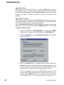
1
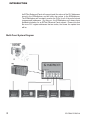
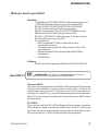
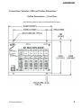
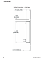
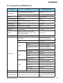
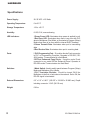
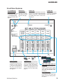
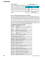
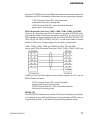
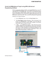
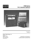
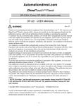
The Most Sensible Automation Products
Direct From the Factory
EZ Multiplexer User Manual
Manual Part Number EZ-MULTIDROP-M
WARNING!
Programmable control devices such as EZMultiplexer are not fail-safe devices and as such must not
be used for stand-alone protection in any application. Unless proper safeguards are used, unwanted
start-ups could result in equipment damage or personal injury. The operator must be made aware of
this hazard and appropriate precautions must be taken.
In addition, consideration must be given to the use of an emergency stop function that is independent
of the programmable controller.
The diagrams and examples in this user manual are included for illustrative purposes only. The
manufacturer cannot assume responsibility or liability for actual use based on the diagrams and
examples.
Trademarks
This publication may contain references to products produced and/or offered by other companies.
The product and company names may be trademarked and are the sole property of their respective
owners. EZAutomation disclaims any proprietary interest in the marks and names of others.
Manual P/N EZ-MULTIDROP-M
© Copyright 2005, EZAutomation
All Rights Reserved
No part of this manual shall be copied, reproduced, or transmitted in any way without the prior written consent of EZAutomation. EZAutomation retains the exclusive rights to all information included
in this document.
MANUFACTURED by AVG AUTOMATION
4140 Utica Ridge Rd. • Bettendorf, IA 52722-1327
MARKETED by EZAUTOMATION
4140 Utica Ridge Road • Bettendorf, IA 52722-1327
Phone: 1-877-774-EASY • Fax: 1-877-775-EASY • www.EZAutomation.net
EZ-MULTIDROP-M
INTRODUCTION
Introduction to the EZMultiplexer
The EZMultiplexer is a communication master unit and was designed to allow
up to 5 EZText Enhanced Panels to communicate with a single PLC. You may
connect 5 of any combination of EZText Enhanced Panels, including the EZ-SP
Set Point Panel. You will program each panel separately in your EZText Enhanced
Programming Software, Multi-Panel System project. After you select Multi-Panel
System in the programming software, you will select an EZText Enhanced
Panel — connected to Port 1, Port 2, Port 3, Port 4, or Port 5 — and configure it
individually. Each EZText Enhanced Panel in a Multi-Panel System may have a
unique configuration. Only the PLC settings are common to all five panels.
When creating a Multi-Panel Project, you can import a panel configuration from
an existing project file — or export it to another project file.
It is important to note that the EZMultiplexer will only read and write to PLC
registers that the panels are currently monitoring. This significantly increases
the speed and performance of a Multi-Panel System.
The same port (PLC/Programming Port) is used for connection to either the PLC or
a programming computer. A MODE switch on the front of the unit (see figure on
page xx) allows you to select PROGRAM (setup) Mode or MULTIPLEXER (run)
Mode. You will use PROGRAM Mode (MODE switch is ON) when Programming
(connected to a computer) and MULTIPLEXER Mode (MODE switch is OFF)
when connected to a PLC. You will use cable P/N EZTEXT-PGMCBL to connect
the Multiplexer to a programming computer. Above the PLC/PROG port are two
LEDs that indicate communication between the Multiplexer and PLC or between
the Multiplexer and a programming computer.
There are 5 panel ports used to connect to any of the EZText Enhanced Panel
models. Above each EZText Enhanced Panel port (COM1, COM2, COM3, COM4,
and COM5) are two LEDs that indicate communication between the Multiplexer
and the EZText Enhanced Panels.
The PLC Attribute settings are the same for each Panel. The baud rate to each
of the panels is fixed. The Multiplexer supports the same PLCs as the EZText
Enhanced Panel. All of the EZText Enhanced Panels in a project are configured
to use the same PLC driver to communicate with the Multiplexer, this is done
automatically by EZText Enhanced Programming Software. The software will
support downloading the PLC driver, retrieving information from the Multiplexer
(revision and PLC attributes), and setting the PLC Attributes.
EZ-EZMULTIDROP-M
1
INTRODUCTION
An EZText Enhanced Panel will request (read) the values of the PLC Addresses
stored in the EZMultiplexer and will write new values to the EZMultiplexer.
The EZMultiplexer will constantly monitor the PLCs for all of the active stored
(programmed) addresses. By doing so, the EZMultiplexer will always have
updated information for an EZText Enhanced Panel request. Please note that
the more PLC register addresses that are active, the slower the update time
will be.
Multi-Panel System Diagram
2
EZ-EZMULTIDROP-M
INTRODUCTION
What you need to get started
Hardware
•
•
•
•
•
•
•
1 EZMultiplexer, P/N EZ-MULTIDROP, master communication unit
1–5 EZText Enhanced Panels (choose from models EZ-220,
EZ-220L, EZ-420, EZ-220P, EZ-SP, EZ-220V, & EZ-220PV)
24 Volt DC Power Supply (FA-24PS recommended)
RS-232C Programming Cable (P/N EZTEXT-PGMCBL) and set
MODE switch to ON to select Program (setup) Mode.
RS-232C or RS-422A PLC Cable (see page 10 for part numbers)
Programmable Logic Controller (PLC)
PC requirements:
— IBM or compatible PC (486 or better) with a mouse
and separate serial port
— VGA display with at least 800 x 600 resolution (1024 x 768
recommended)
— Standard Windows 95/98 (Second Edition)/NT4.0/2000®
requirements
— CD ROM Drive
Software
•
Need HELP?
EZText Enhanced Programming Software (P/N EZ-TEXTEDIT-E)
PLEASE NOTE: The section on Troubleshooting at the end of this
manual should help you with most problems you might encounter.
Onscreen HELP
One of the most important features of the EZText Enhanced Panel Programming
Software is the availability of context sensitive onscreen help. To access the
Help windows, simply press the F1 function key while on the topic where you
need help. For example, if you need help while working with panel configuration,
hit the F1 function key when that dialog box is open and a pop-up HELP window
will be displayed.
PLC HELP
If you need help with the PLC to EZText Enhanced Panel Interface, consult the
EZText Enhanced Panel Programming Software Help. Each PLC Driver has a
Help Topic that lists the error messages and provides an explanation for each.
Also provided are PLC to EZText Enhanced Panel wiring diagrams.
EZ-EZMULTIDROP-M
3
INTRODUCTION
Technical Support
Although most questions can be answered with EZText Enhanced HELP or the
manuals, if you are still having difficulty with a particular aspect of installation
or system design, technical support is available at 1-877-774-EASY, Monday
through Friday, 6 a.m. to Midnight CST, or FAX us at 1-877-775-EASY. Visit
our website at www.EZAutomation.net.
4
EZ-EZMULTIDROP-M
HARDWARE
Connections, Switches, LEDs and Outline Dimensions
Outline Dimensions — Front View
(see following page for side view and depth dimensions)
EZ-EZMULTIDROP-M
5
HARDWARE
Outline Dimensions — Side View
6
EZ-EZMULTIDROP-M
HARDWARE
PLCs Supported by EZMultiplexer
PLC Brand
Allen Bradley
Model
Protocols Supported
MicroLogix 1000/1200/1500, SLC500,
5/01, /02, /03, /04, /05 and PLC5
DF1 Half Duplex; DF1 Full
Duplex
PLC 5
DF1
Aromat
Aromat
Mewtocol COM
Control Techniques
Unidrive 4-wire
Binary
Control Technology
Corporation (CTC)
CTC 2600, 2700, and 5100
CTC Binary
EZAutomation
EZPLC
EZ Protocol
General Electric
90/30 and 90/70 Versamax
SNPX
Idec
Idec
Computer Link
Mitsubishi
FX Series (all)
FX, Direct
Modicon
984 CPU, Quantum 113 CPU, AEG
Modicon Micro Series 110, CPU: 311-xx,
411-xx, 512-xx, 612-xx
Modbus RTU
Omron
C200, C500, CQM1, CPM1
Host Link
DL05, DL06
K-Sequence; DirectNet;
Modbus (Koyo addressing)
DL105
K-Sequence
D2-230
DL205
Direct Logic
DL305
DL405
K-Sequence
D2-240
K-Sequence; DirectNet
D2-250/D2-250 - 1/260
K-Sequence; DirectNet;
Modbus (Koyo addressing)
D2-240/250/260 w/DCM
DirectNet
D3-330/330P
DirectNet
D3-340
DirectNet
D3-350
K-Sequence; DirectNet;
Modbus (Koyo addressing)
D3-350 w/DCM
DirectNet
D4-430
K-Sequence; DirectNet
D4-440
K-Sequence; DirectNet
D4-450
K-Sequence; DirectNet;
Modbus (Koyo addressing)
All with DCM
DirectNet
Entivity (Think-n-Do)
Modbus RTU
Siemens
Siemens S7300/400 PLCs MPI Adaptor
3964R
Texas Instruments
TI5x5 series,TI505, TI545-1102, TI545-1104
TBP (Transparent Byte Protocol)
or NITP (Non-Intelligent Terminal
Protocol)
EZ-EZMULTIDROP-M
7
HARDWARE
Specifications
Power Supply:
20–30 VDC <2.5 Watts
Operating Temperature:
0 to 60 °C
Storage Temperature:
–20 to +60 °C
Humidity:
0–95% R.H, noncondensing
LED Indicators:
1 Green Power LED: Illuminates when power is applied to unit
1 Red Error LED: Illuminates when there is an error with PLC
when in Multiplexer (Run) Mode, or illuminates in Program (Setup)
Mode when there is an error with the internal EXEC firmware.
6 Green Transmit Data: Illuminates when port is transmitting
data
6 Red Receive Data: Illuminates when port is receiving data
Ports:
1 PLC/Programming Port: 15-position female D-sub connector
to PLC or Programming Computer. Operates in RS-232C, RS422A modes. Communicates at a fixed Baud.
5 EZText Enhanced Panel Ports: 9-position male D-sub
connector to any model EZText Enhanced Panel. Operates in
RS-422A mode. Communicates at a fixed Baud.
Switches:
1 Mode Switch: Used to switch panel between Program (Setup)
Mode and Multiplexer (Run) Mode.
1 PLC Terminator Resistor: Should be turned ON if the
Multiplexer is the first or last node on the network. Set to ON, the
RS-422 signal is terminated.
External Dimensions:
6.5” x 5.0” x 0.901” (165.097 x 126.995 x 22.885 mm); Depth
including connector 1.544” (39.210 mm)
Weight:
0.9 lbs.
8
EZ-EZMULTIDROP-M
HARDWARE
Front Panel Features
PLC TERMINATOR
RESISTOR Switch
Set to ON when unit is first
or last node on network
— the RS-422/RS-485
signal is terminated. See
page 12.
MODE Switch
Set to ON when programming, and set to
OFF when connected
to a PLC. See page
12.
ERROR LED
Illuminates in PROGRAM mode when
there is an error with the internal firmware
(EXEC). Illuminates in MULTIPLEXER
(run) Mode when there is a PLC error.
See page 11.
POWER LED
Illuminates when power
is applied to the EZMultiplexer. See page 12.
OR
Power Terminals
Connect (+) on the unit to the
(+) lead of your power source.
Connect (-) on the unit to the
(-) lead, and chassis GND (on
the unit) is connected to the
chassis ground of the cabinet.
See page 10.
EZ-EZMULTIDROP-M
PLC/PROG Port
15-position Male D-Sub Connector.
Connect programming PC to this
port using cable P/N EZTEXTPGMCBL or connect to PLC using
the PLC cable appropriate for your
type PLC. See PLC Cable table,
page 10.
COM1, COM2, COM3, COM4, and
COM5 Ports
Five 9-position Male D-Sub connectors. Connect up to 5 (any
model) EZText Enhanced Panels
using cable P/N EZ-MULTI-CBL.
See page 11.
TXD and RXD LEDs
Twelve LEDs that illuminate to
show transmit and receive data
activity for the port directly below.
See page 11.
9
HARDWARE
Power Terminal
It is recommended you use a regulated
power source isolated from relays,
valves, etc. Connect (+) on the unit
to the (+) lead of your power source.
Connect (-) on the unit to the (-) lead,
and chassis GND (on the unit) is
connected to the chassis ground of the
cabinet.
Power Connector
(P4, Phoenix 3-pin Header, 0.2 cntr)
PLC or Programming (Computer) Port: PLC/PROG
There is one 15-position female D-Sub Connector, operating in RS-232C, RS422A, or RS-485A modes, at a fixed Baud Rate. This port (PLC/Programming) is
used for connection to either a PLC or a programming computer. A switch on the
front of the unit (see MODE Switch, below) allows you to select Program (setup)
Mode or Multiplexer (run) Mode. You will use Program Mode when programming
(connected to a computer) and Multiplexer Mode when connected to a PLC. You
will use one of the PLC cables listed in the table below to connect to your type
PLC. For programming, use cable P/N EZTEXT-PGMCBL.
PLC/PROG Port LEDs: TXD and RXD
10
EZ-EZMULTIDROP-M
HARDWARE
Above the PLC/PROG port are two LEDs that indicate communication between the
Multiplexer and PLC or between the Multiplexer and a programming computer.
1 TXD (Transmit) Green LED - when illuminated
indicates that the port is sending data
1 RXD (Receive) Red LED - when illuminated indicates
that the port is receiving data
EZText Enhanced Panel Ports: COM1, COM2, COM3, COM4, and COM5
There are five 9-position male D-Sub Connectors, operating in RS-422A mode,
at a fixed Baud Rate. These ports are used for connection for up to five of any
EZText Enhanced Panel including the Set Point Panel (EZ-220, EZ-220V, EZ220L, EZ-420, EZ-220P, EZ-220PV, & EZ-SP). You will need a cable to connect
panels to COM ports. A wiring diagram for the cable is shown below.
COM1, COM2, COM3, COM4 and COM5 Port LEDs: TXD and RXD
Above each EZText Enhanced Panel port (COM1, COM2, COM3, COM4, and
COM5) are two LEDs that indicate communication between the PLC and the
EZText Enhanced Panels:
5 TXD (Transmit) Green LED - when illuminated
indicates that the port is sending data
5 RXD (Receive) Red LED - when illuminated indicates
that the port is receiving data
ERROR LED
The ERROR LED indicates an error with the PLC when in Multiplexer (run) Mode,
or it indicates an error with the Multiplexer’s internal firmware (EXEC) when in
Program (setup) Mode. It also flashes when switching between modes.
EZ-EZMULTIDROP-M
11
HARDWARE
•
When the EZMultiplexer enters the Multiplexer Mode the ERROR
LED will blink on for 100 Msec and off for 100 Msec 5 times.
•
When the EZMultiplexer enters the Program Mode the ERROR LED
will blink on for 400 Msec and off for 100 Msec 2 times.
•
While the EZMultiplexer is in Multiplexer Mode (Run Mode) the red
ERROR LED will illuminate to indicate an error with the PLC. The
ERROR LED will illuminate for 2 seconds and then turn off while the
PLC driver tries to communicate with the PLC again. If there was an
error with the PLC, the PLC message will be displayed on all of the
EZText Enhanced Panels that are connected and communicating with
the EZMultiplexer.
•
When the Multiplexer Panel is in Program Mode —either because the
EZText Enhanced Programming Software is sending new firmware,
or because on power up the Boot found that there is an invalid
EXEC— the ERROR LED will blink on for 1 second and off for 200
Msec continuously. YOU MUST reload the firmware, ensuring you
have the correct firmware.hex file.
POWER LED
The Power LED illuminates when power is applied to the unit.
Mode Switch
This switch allows you to switch the EZMultiplexer between Programming (setup)
Mode and Multiplexer (run) Mode.
PLC Terminator Resistor Switch
Used to switch the RS-422 termination resistor, ON or OFF. If the EZMultiplexer
is the first or last node on the network, set the switch to ON to prevent signal
distortion. Set to ON, the RS-422 signal is terminated.
12
EZ-EZMULTIDROP-M
CONFIGURATION
Create the EZMultiplexer Project using EZText Enhanced
Programming Software
With the programming software installed, connect the EZMultiplexer to your PC
using the P/N EZTEXT-PGMCBL cable. Set the MODE Switch on the front panel
of the Multiplexer to PROGRAM (ON). Connect from 1 to 5 EZText Enhanced
Panels to the COM1, COM2, COM3, COM4, and/or COM5 ports on the front
panel of the EZMultiplexer. Apply 24 VDC to the EZText Enhanced Panels and
EZMultiplexer power connectors. Click on the EZText Enhanced Programming
Software icon to start the program.
1.
From the Welcome screen, click on the New System button.
2.
The Create Project window will appear. Type in the name of your
project in the File name field. Click on Save. (If you don’t want your
project saved to the default “Project” folder, navigate to the directory
and/or folder where you want it to reside.)
In Step 1, select Multi-Panel System. When Multi-Panel System
is selected, Step 1a on the right hand side of the screen will become
available. You will also notice that two buttons at the bottom of the screen
will change to “Write to Multiplexer” and “Read from Multiplexer.” You
may program up to 5 panels connected to a Multiplexer. Click on the
Port 1, Port 2, Port 3, Port 4, or Port 5 button.
3.
Click here to open
this window
EZ-EZMULTIDROP-M
13
CONFIGURATION
a.
Under Step 1a, Select a Panel, you will choose the first panel that
you want to configure. There are three ways that you can choose
the panel type for each port. Click on Port 1 and then click on the
Select Panel Type button under Step 1, or double click on Port
1, or click on Port 1 and then right click your mouse to open the
popup menu and choose Select Panel. You may configure the
panel connected to Port 1, 2, 3, 4, or 5 in any order. They do not
have to be configured sequentially.
Right Click Menu —
choose Select Panel
4.
14
b.
The Select Panel dialog box will open. Under Panel Type, click on
the panel type that is connected to that port. A picture of the panel
will appear under Panel Preview, and key features of the panel
are displayed under Panel Attributes.
c.
Click on the OK button to select and close the dialog box. The Panel
type you have selected will appear above Port 1, 2, etc.
You may also import a panel configuration from another project. Click
on the Port/Panel that you want to copy the project to. Right click
EZ-EZMULTIDROP-M
CONFIGURATION
your mouse button to bring up the Right Click Menu. Select Import
Configuration.
5. The Open project dialog will open. You may select
either a Single Panel or a Multi-Panel project. Click
on the project you want to import to highlight it, and
then click on the Open button.
6. If you have selected a Multi-Panel project to import, the
dialog box to your right will open allowing you to select
the particular Port/Panel configuration that you want
to import into your current project. Click OK. In a Multi-Panel EZText
Enhanced project, you may only import one Port/Panel configuration
from an existing project into one Port/Panel in the current project with
each Import Configuration command.
EZ-EZMULTIDROP-M
15
CONFIGURATION
7.
In Step 2, Select PLC, you will choose
the type PLC you are using. You will only
be able to select one PLC type per project
(whether it is a Single Panel System
or a Multi-Panel System). If you need
more information on PLC configuration,
consult your EZText Enhanced Panel
User Manual or your EZText Enhanced
Programming Software Help Topics, or your
PLC Manual.
a.
Click on the DOWN arrow next to the Select PLC field to view
the drop down menu of available PLCs. Click on the PLC Type to
select.
b.
Click on the Press for communication configuration for Selected
PLC button.
c.
The PLC Communications Attributes window will appear for the
PLC you have selected. Set the appropriate attributes and Click on
the OK button.
During configuration, ensure that your address and communications
parameters match the PLC port settings. There will be a selection for
PLC timeout. When the panel sends a message to the PLC and does
not receive a response or does not understand the response, it will wait
the timeout period before sending the message again.
16
EZ-EZMULTIDROP-M
CONFIGURATION
8.
For Step 3, click on the Configure Panel System PLC Addresses
button. The Panel System PLC Address Setup window will appear.
Step 3 is the same whether you have a Single Panel System or a MultiPanel System. For each Port/Panel you have connected, follow the
instructions in the EZText Enhanced Panel User Manual that came with
your unit or consult the EZText Enhanced Programming Software Help
Topics.
EZ-EZMULTIDROP-M
17
CONFIGURATION
Right Click Menu — Items Unique to Multi-Panel System Configuration
To access the right click menu, put your cursor arrow in the Port 1, Port 2, Port
3, Port 4, or Port 5 box on the Main Configuration Screen and right click your
mouse (as shown below). The Right Click Menu will appear.
If you have not yet selected a panel
type to associate with the port, some
menu items will not be available
—they will appear as grayed out.
The Port currently
selected for configuration will appear in yellow. Those ports not
yet configured or without an EZText Enhanced Panel associated with it will appear in gray. Ports with an EZText Enhanced
Panel associated with it that is not selected for configuration
will appear in green.
The six menu items available on the Multi-Panel System’s Right
Click Menu are described below.
Select Panel
The Select Panel menu item allows you to select an EZText Enhanced Panel Type
to assign to the port you have
clicked on. You may click on a
port to reassign the panel type
at any time. If the Panel/Port
has already been configured,
and you choose another type
panel, you may lose information
when switching if the panel types
are not compatible. You may
also open this screen by double
clicking in the Port/Panel box
under Step 1a, Select Panel, or
click on the Select Panel button
under Step 1.
18
EZ-EZMULTIDROP-M
CONFIGURATION
Delete Panel
Click in the Panel/Port box that you want
to select on the Main Configuration Screen.
Right click to bring up the menu and then
click on the Delete Panel menu item. The
message to the right will appear. Click on
Yes to Delete the Panel configuration for
that Port or No to abort the operation.
Import Configuration
If you have an existing Single
Panel or Multi-Panel project that
has the panel configuration that
you want for your current project,
click on Import Configuration.
The window to the right will appear.
Click on the EZText Enhanced
Project where the configuration
that you want to import resides.
If you select a Multi-Panel project,
the window shown to the right will
appear allowing you to select the
particular Panel/Port to import. Click OK to import. The
following warning will appear.
Click on Yes to continue, No to abort the import.
Export Configuration
You may also export a Single Panel
or Multi-Panel Configuration. Click
on Export Configuration. The
Save As screen will appear. Type
in the name of the project where
you want to save the selected
panel configuration. Click on the
Save button to export.
EZ-EZMULTIDROP-M
19
CONFIGURATION
Information
Click on the panel you wish to receive information on and then click on
Information to access the Panel Status window for the Panel/Port you have
selected. A picture of the panel type, key features of the current panel, and Panel
and PLC information is provided (panel model, Firmware Revision, Memory Size,
PLC Driver, and PLC Driver Revision number are displayed).
Upgrade Firmware
Consult your EZText Enhanced Panel User Manual that came with your unit
before you upgrade your panel firmware!
Click on the panel you wish to upgrade, right click your mouse for the menu, and
then click on Upgrade Firmware. The following window will appear. Select the
correct firmware and click on the OK button.
20
EZ-EZMULTIDROP-M
CONFIGURATION
Main Menu Items Unique to Multi-Panel System Configuration
There are some differences in the Panel Menu in the Main Menu Bar when you
are configuring a Multi-Panel System.
Write Project/Read Project/Verify
The Write Project will write the current project to the EZMultiplexer and all
defined EZText Enhanced Panels, and Read Project will read the project from
the EZMultiplexer and save it to your current project. Verify will compare the
current open project with the program loaded in the EZMultiplexer. The Reading
from Panel (“Panel” in this instance refers to the EZMultiplexer) window will
appear, showing the progress of the verification. When complete, a message
will appear telling you if they are the same or if they are different. You can also
Write to Multiplexer and Read from Multiplexor by clicking on the buttons
so named at the bottom of the Main Configuration Screen.
Clear Memory
This will clear the entire project stored
in the EZMultiplexer memory and all
connected EZText Enhanced Panels’
Memory. Please be aware that this
means that you will clear all EZText
Enhanced Panel configuration. (In a
Multi-Panel project, the information for
all EZText Enhanced Panels is stored
in the Multiplexer.)
Information
If you click on Information from the Panel
Menu in a Multi-Panel Project, the Panel
Status window will open. You will receive
information about the Multiplexer instead of
a particular panel in the project. (If you want
information on a panel, use the right click
menu Information option.)
EZ-EZMULTIDROP-M
21
CONFIGURATION
Upgrade Firmware
Not available in a Multi-Panel Project. To upgrade EZMultiplexer firmware,
see paragraph below. To upgrade the firmware in an EZText Enhanced Panel
connected to the EZMultiplexer, use the Right Click Menu and click on Upgrade
Firmware (see Right Click Menu descriptions previously discussed in this
manual)/
Upgrade Mux Firmware
There may be occasional upgrades to the EZMultiplexer’s internal software, also
referred to as the Exec or Firmware. Check the EZAutomation website periodically
for information about software and firmware upgrades.
Click on Upgrade Mux Firmware to begin the upgrade process. (Mux stands for
Multiplexer.) Click on Browse to find for the EZMUXxy .hex file. Click on OK.
To Upgrade Mux Firmware:
1.
Place the EZMultiplexer in PROGRAM Mode. To do so, set the MODE
Switch on the front panel of the EZMultiplexer to PROGRAM (ON).
2.
Under the Panel Menu, click on Upgrade Mux Firmware. The following
screen will appear.
3.
Click on the Browse button. A window will open to the default folder,
Firmware (located in the EZText Enhanced Program directory). If the
firmware file has been downloaded from the EZAutomation website to
another location, navigate to the new firmware file (.hex file).
There is a specific file name for the EZMultiplexer firmware. Don’t
confuse it with EZText Enhanced Panel firmware (.hex) files. Look for
the file named EZMUXxy.hex. The “x” represents the major revision
of the firmware (e.g., A). “y” represents the minor revision (e.g., 1).
22
EZ-EZMULTIDROP-M
CONFIGURATION
Make sure that you select the correct firmware.hex file for your the
EZMultiplexer, and send the upgrade to the panel.
4.
Select the appropriate COM port under Port Selected (if necessary)
and click on the Start button to begin downloading the firmware to
the EZMultiplexer. A status bar will let you know when the upgrade is
complete. Click on Close when complete.
If the red ERROR LED is flashing you have loaded an invalid EXEC (firmware.
hex file). The ERROR LED will blink on for 1 second and off for 200 Msec
continuously. YOU MUST reload the firmware, ensuring you have the correct
firmware.hex file.
EZ-EZMULTIDROP-M
23
MAINTENANCE
Maintenance
Fuse Reset
The EZMultiplexer features an AUTO-RESET fuse (0.65 Amp polyfuse). It is reset
by removing power for 5 minutes and then reapplying power to the unit.
24
EZ-EZMULTIDROP-M
TROUBLESHOOTING
Troubleshooting
In this section we will explain how to isolate potential problems. If you cannot
isolate and remedy the problem using the procedures we have outlined below,
call technical support. For a list of EZText Enhanced Panel, EZText Enhanced
Programming Software, and PLC Driver Error Messages, see Appendix C in your
EZText Enhanced Panel User Manual.
Problem: Multiplexer doesn’t have power.
1. Check the green Power LED on the front of the panel. It will illuminate
when power is applied to the unit. If it is not illuminated, check to make
sure power is applied to the unit.
2. Check power supply or replace.
3 . Ensure that the power terminal connections on the front panel of the
multiplexer are wired correctly.
Problem: Multiplexer is not communicating with programming
computer.
1. Ensure that the MODE Switch on the front panel of the multiplexer is
set to PROGRAM (ON).
2. Check cable, ensure that it is the correct cable and that it is properly
connected at both ends.
3. Check multiplexer for power.
4. Check to ensure the correct PC COM port is selected in the EZText
Enhanced Programming Software and that it is available in the PC.
5 Check to ensure that EZText Enhanced Panels are in SETUP Mode.
Press the UP Arrow Pushbutton and hold while simultaneously
pressing the DOWN Arrow Pushbutton. The panels MUST be in setup
mode to communicate with the programming computer through the
Multiplexer.
6. Check the COM1 setting in Setup Mode on the EZText Enhanced
Panel.
Problem: Multiplexer is not communicating with PLC.
1. Ensure that the MODE switch on the front panel of the multiplexer is
set to MULTIPLEXER (OFF).
2. Check to ensure cable from PLC to Multiplexer is the right cable, and
connected properly.
3. If Multiplexer is the first or last node on a network, check to make sure
that the PLC TERMINATOR RESISTOR switch on the front panel of
the multiplexer is set to TERMINATED (ON).
4. Check PLC settings:
a. Is PLC system powered?
b. Is PLC COM Port properly configured?
c. If there is a RUN switch on PLC, is it in the term/remote mode?
EZ-EZMULTIDROP-M
25
TROUBLESHOOTING
Problem: Multiplexer is not communicating with one or more EZText
Enhanced Panels.
1.
2.
Check to ensure that the cable from the Multiplexer to the EZText
Enhanced Panel is the correct cable and connected properly.
Check to ensure that the MODE switch is set properly. To program the
panels the MODE switch must be ON — in the PROGRAM Mode. To
run the panels the MODE switch must be OFF — in the MULTIPLEXER
Mode.
Problem: ERROR LED is illuminated.
The ERROR LED indicates an error with the PLC when in Multiplexer (run) Mode,
or it indicates an error with the Multiplexer’s internal firmware (EXEC) when in
Program (setup) Mode. It also flashes when switching between modes.
•
When the EZMultiplexer enters the Multiplexer Mode the ERROR
LED will blink on for 100 Msec and off for 100 Msec 5 times. This is
normal.
•
When the EZMultiplexer enters the Program Mode the ERROR
LED will blink on for 400 Msec and off for 100 Msec 2 times. This is
normal.
•
While the EZMultiplexer is in Multiplexer Mode (Run Mode) the red
ERROR LED will illuminate to indicate an error with the PLC. The
ERROR LED will illuminate for 2 seconds and then turn off while the
PLC driver tries to communicate with the PLC again. If there was an
error with the PLC, the PLC message will be displayed on all of the
EZText Enhanced Panels that are connected and communicating
with the EZMultiplexer. See Problem: Multiplexer is not
communicating with PLC.
•
When the Multiplexer Panel is in Program Mode— either because the
EZText Enhanced Programming Software is sending new firmware,
or because on power up the Boot found that there is an invalid EXEC
— the ERROR LED will blink on for 1 second and off for 200 Msec
continuously. YOU MUST reload the firmware, ensuring you have the
correct firmware.hex file. See section on installation of new firmware,
this manual.
26
EZ-EZMULTIDROP-M
TROUBLESHOOTING
Still need Help?
Check the EZText Enhanced Panel Hardware Manual and/or EZText Enhanced
Programming Software Manual/Help Topics for additional troubleshooting
information. You also have two additional sources for more information other
than this manual.
Visit our website at www.EZAutomation.net
Our web site contains all of this information, any new feature releases, technical
support, plus much more.
Call our Technical Support Group Monday–Friday 6 a.m. to Midnight at 1-877774-EASY or FAX us at 1-877-775-EASY.
If you have any questions that you can’t find an answer to, give us a call at the
number above and we will be glad to assist you.
EZ-EZMULTIDROP-M
27
This page intentionally left blank.
28
EZ-EZMULTIDROP-M