1
EMPOWERMENT
SENIOR DESIGN II: EE-41440
FINAL DOCUMENTATION
SANTIAGO GARCÉS | XIFAN FRED HONG | ELIZABETH RUHL
4 MAY 2010
EMPOWERMENT:
FINAL DOCUMENTATION
PAGE 2
TABLE OF CONTENTS
1. Introduction
1.1 Problem and Solution
1.2 System Requirements
1.2.1 Overall System
1.2.2 Generation Subsystem Requirements
1.2.3 Monitoring Subsystem Requirements
1.2.4 Storage Subsystem Requirements
1.2.5 Load Subsystem Requirements
1.2.6 Future Enhancement Requirements
1.3 High Level Design
1.4 Expectations
2 Project Description
2.1 System Theory of Operation
2.2 System Block Diagram
2.3 Generation Description
2.3.1 Wind Power Generation
2.3.2 Solar Power Generation
2.3.3 Power Generation Testing
2.4 Monitoring and Control
2.4.1 Microcontroller
2.4.2 Hardware: Sensors
2.4.3 Hardware: LCD Display
2.4.4 Hardware: Data Storage
2.4.5 Software:
2.5 Storage
2.5.1 Battery
2.5.2 Relays
2.5.3 Switches
2.6 Load
2.7 System Housing and Construction
4
4
4
4
5
6
6
7
7
7
8
9
9
9
10
10
12
13
14
14
16
18
19
20
24
24
24
26
26
27
3 System Integration
29
4 User's Manual
31
3.1 Testing Methods
3.2 Fulfilling Requirements
4.1 System Installation and Set-up
4.1.1 Additional Hardware Selection
4.1.2 Connections
4.2 Everyday Use
4.3 Troubleshooting
5 Conclusions
5.1 Results
5.2 Future
http://seniordesign.ee.nd.edu/2010/Design%20Teams/Empowerment/Welcome.html
29
30
31
31
31
32
33
34
34
34
EMPOWERMENT:
FINAL DOCUMENTATION
PAGE 3
Appendix A: Schematics and Board Layouts
A1: Main Board Schematic
A2: Main Board Layout
A3: Sensor Board Schematic
A4: Sensor Board Layout
A5: Hall Effect Board Schematic
A6: Hall Effect Board Layout
Appendix B: Software
B1: A2D.h
B2: A2D.c
B3: Relay.h
B4: Relay.c
B5: RotSens.h
B6: RotSens.c
B7: RTClib.h
B8: RTClib.c
B9: spiLCD.h
B10: spiLCD.c
B11: main.c
Appendix C: Bill of Materials
http://seniordesign.ee.nd.edu/2010/Design%20Teams/Empowerment/Welcome.html
36
37
38
39
40
41
42
42
46
46
47
48
49
50
54
55
61
68
EMPOWERMENT:
FINAL DOCUMENTATION
PAGE 4
1 INTRODUCTION
1.1 Problem and Solution
People all over the world make do without electricity. Living without electricity in
many cases means living without hope of development. Lack of electricity keeps
people especially susceptible to disease, eliminates the possibility of studying or any
sort of income generation occurring after sunset, and keeps rural populations out of
touch with the rest of the world. However, for many developing countries, the
bureaucratic and technical difficulties associated with installing, much less maintaining,
effective infrastructure make those improvements out of the question. The solution lies
in providing low cost, robust, off-the-grid energy generation systems. We are hoping to
design a system that uses two renewable energy sources, solar and wind, to provide
power for a household. We plan for the system to power a useful appliance reliably, to
store excess energy, and to require minimal user maintenance.
For many people in the developing world, the only available energy sources are dirty,
unsustainable, and often expensive. Some of these sources include hard-to-find fossil
fuels that emit green house gasses. Other carbon-based fuels include animal waste or
firewood, both of which are time consuming to gather and give off unhealthy smoke
and particulates when burned. In addition, using wood as fuel leads to deforestation,
draughts, and further impoverishment. Living without electricity in many cases means
living without hope of development. Lack of electricity keeps people especially
susceptible to disease, eliminates the possibility of studying or any sort of income
generation occurring after sunset, and keeps rural populations out of touch with the rest
of the world. However, for many developing countries, the bureaucratic and technical
difficulties associated with installing, much less maintaining, effective infrastructure
make those improvements out of the question.
Off-grid small-scale power generation systems that rely on renewable fuels are a clear
answer. In addition, we would like to make use of readily available materials that can
be found or manufactured easily in many places around the world. Our design
harnesses energy from both the sun and wind. We plan to use inexpensive crystalline
silicon photovoltaic cells and a wind turbine connected to an old car alternator to first
produce the electricity. Then we will use circuitry to add the power together and
charge a 12V battery. The battery will then be used to power appliances.
1.2 System Requirements
1.2.1 Overall System
Our system has four main subsystems: energy generation, monitoring, storage, and
load.
Our generating subsystem consists of a small wind turbine connected to a car
alternator, and a set of monocrystalline silicon photovoltaic cells. The combined efforts
of these two power sources should be able to provide between 20-25 amps at 12 volts.
http://seniordesign.ee.nd.edu/2010/Design%20Teams/Empowerment/Welcome.html
EMPOWERMENT:
FINAL DOCUMENTATION
PAGE 5
The generation is dependent on mechanical design decisions and the environment; by
choosing the appropriate pulley system and by optimizing the direction of the solar
panels and the turbine, the generated power at full production levels should be around
240W-300W.
The monitoring subsystem consists of a variety of sensors feeding into a
microcontroller, which will monitor and control the behavior of the system according to
various threshold voltages. The microcontroller will read in the voltages from the
generation system and the battery, the current from the solar panels, the alternator, and
the battery, and the rpm of the turbine. The up-to-date results of these sensors will be
displayed to the user on an LCD display. Also included in this subsystem is an SD chip,
which will store the data being gathered by the sensors. Having this information,
especially in the early stages of the project, will enable us to analyze and optimize the
system.
The storage subsystem consists of a 12V lead acid battery, relays, and a passive deep
discharge protection circuit. The monitoring subsystem will keep the microcontroller
up-to-date on the voltage of the battery. If the battery voltage reaches above 14V, then
the microcontroller will signal the relay to disconnect the battery from the generating
subsystem in order to protect the battery from overcharging. If the battery falls below
10V, the microcontroller will signal another relay to disconnect the battery from the
load. As an extra safeguard, the inverter automatically disconnects when the battery
falls below 9.5V. These protection measures should extend the battery’s lifetime and
the usability of the system. The relay on the generation side plays an additional role.
The turbine will not be able to start moving if it starts off loaded. The microcontroller
needs to open the relay so that the turbine is disconnected from the battery until the
rotor gains speed. Then the connection can be made and the alternator can begin
generating energy.
On the load side we will have dual output. First we will have a 12 V DC ideal for
appliances designed for cars, RVs, or high efficiency LEDs. We will also have an
inverter that produces 110 VAC ideal for most standard appliances.
1.2.2 Generation Subsystem Requirements
Solar: The solar panels should output a little above 12V for safe charging. In any
scenario, the power output of the solar panels, due to budget and space restrictions, will
be much lower than the output of the alternator when it is running. However, to charge
a 12V battery on solar power alone within one day, approximately 40W is necessary.
This estimate is based on solar systems already used in the field and advice from
Professor Freeland. Therefore this subsystem requires enough solar cells to produce
around 40W.
Wind: Charging a battery safely requires a fairly stable voltage. Any alternator selected
needs to have a regulated 12V output, or the voltage from the alternator needs to be
http://seniordesign.ee.nd.edu/2010/Design%20Teams/Empowerment/Welcome.html
EMPOWERMENT:
FINAL DOCUMENTATION
PAGE 6
rectified in some way before reaching the battery.
We are anticipating wind speeds of around 15-20mph, which corresponds to 15-20A.
Wind speeds increase with vertical height, so the turbine can take better advantage of
wind if it is elevated significantly.
1.2.3 Monitoring Subsystem Requirements
Sensors: The voltages being monitored will hover around 12V, so the voltage sensors
need to be able to measure with some accuracy at that level. The current coming from
the solar panels will be less than 1.15A, the current from the alternator will hopefully be
around 30A, and the current from the battery will most likely be somewhere in
between. The current sensors need to be able to measure with some accuracy at these
varying levels. The average speed of our wind turbine, predicted by the plans, will be
around 600 rpm. We need a rotation sensor that can measure with some accuracy at
this speed. We also need some way to convert the signals from the sensor into an rpm
value using software.
Microcontroller: We have decided to run our board at 5V, so the microcontroller needs to
operate at that voltage. Many of our components will require SPI, so the
microcontroller must be able to handle that.
LCD Display and User Interface: This display is the main way the user will get to see what
kind of power the system is producing and what the current charge of the battery is,
especially if the user does not have a computer or any other way to read the SD card.
The interface and print-out to the screen should be intuitive and easy to interpret.
Data Storage: We want some way to record the outputs from the sensors over an
extended period of time. This feature will be particularly useful for optimizing the
system and determining what conditions produce the most power. In order for users to
make sense of the data recorded, the log should ideally also include some reference to
the date and time of each reading. This might require an additional Real Time Chip.
This also might require the user to input the starting date and time into the
microcontroller at the beginning of recording. This would require a user interface with
push buttons. The system needs to be large enough to store at least 30 days of data at a
time.
1.2.4 Storage Subsystem Requirements
Battery: The system requires a 12V battery. The system is intended for rough conditions
and continuous use, so a robust battery that is suited for float charging is optimal.
Ideally, the battery should also be able to withstand deep discharge without complete
failure, as the unpredictable nature of solar and wind energies might strand the system
without any fuel for unknown lengths of time.
Relays: The relays are responsible for either conducting or disconnecting the current
http://seniordesign.ee.nd.edu/2010/Design%20Teams/Empowerment/Welcome.html
EMPOWERMENT:
FINAL DOCUMENTATION
PAGE 7
between the generators, battery, and load. Therefore they must be robust enough to
handle the high amounts of current. They will be receiving a signal from the
microcontroller to switch, so they must respond to a signal of less than 5V. This system
is trying to conserve energy at every opportunity, so these relays should also ideally not
waste much, if any, power while engaged.
1.2.5 Load Subsystem Requirements
Inverter: Most easy to find appliances that a family would want to power run off of AC
power. The battery stores power in DC. Therefore, the system requires an inverter that
can take power from a 12V DC battery and create AC power appropriate for the
appliances that the user wants to power.
DC Output: The user might also have DC powered appliances, and the system should
be able to handle these too. The DC output should provide 12V of DC in a way that is
easy for the user to access and use.
1.2.6 Future Enhancement Requirements
An increase in power production could be achieved by optimizing the wind turbine
design. The mechanics of the turbine could easily be altered without affecting the
electronics of the system as long as the design uses an alternator with an internal
regulator that outputs 12V DC. More solar panels could also be added easily, provided
they are also around 12V and added in parallel.
The SD storage system and user interface have great opportunities to be enhanced in
the future. Our goals for this project are simply to have the real-time values of the
sensor being displayed on the LCD. In the future, the system could display more
calculated values and the user could perhaps search through past records on the LCD
screen. The possibilities for this expansion are limited by the processing power of the
microcontroller and the available space in the data storage system.
More batteries could be added in parallel and charged simultaneously to increase
power.
The current system will most likely only be able to generate enough power for one
appliance at a time. In the future, as the other energy generation and storage
enhancements are implemented, the system might be able to run multiple loads at once.
This could require additional outputs for the inverter.
1.3 High Level Design
Power will be generated by two sources, solar and wind. A monocrystalline silicon
photovoltaic cell will produce DC power. A wind turbine will drive a car alternator
with a built-in voltage regulator and rectifier to also produce DC power. The two
energy sources will be connected in parallel, and the combined power will begin to
charge the battery.
http://seniordesign.ee.nd.edu/2010/Design%20Teams/Empowerment/Welcome.html
EMPOWERMENT:
FINAL DOCUMENTATION
PAGE 8
Current, voltage, and rotation sensors monitor the power generation system to calculate
the amount of power being generated at all times. The voltage and current of the
battery is also measured at all times. The results of these sensors is received by the
microcontroller and then stored in a data storage system. We have chosen an SD Card
and are using an SPI interface to communicate with it. The results of these sensors will
also be displayed to the user on an LCD screen, also using an SPI interface.
To protect the battery from over- and undercharging, the system has a few safeguards.
In the first case, the microcontroller will monitor the battery voltage level. In the case of
over-charging, the microcontroller will open a relay connecting the generating systems
to the battery. In the case of undercharging, the microcontroller will open a relay
connecting the battery to the load. The inverter we have selected also automatically
disconnects when it detects a battery charge lower than 9.5V. In the case that the user
wants to override the microcontroller or the microcontroller fails, the system will also
include manual switches to control the connections between the battery and the rest of
the system.
Power from the battery will enter an inverter so that users may power their traditional
AC appliances. A DC power option will also be available by simply connecting the load
to the battery terminals, which will be easily accessed.
The energy generation components will be most likely operated outdoors, some
distance from the appliances needing to be powered. Cables carrying the power and
the rotational sensor signal will need to be run some distance before entering the main
system box. The main system box will house the main board, the monitoring system,
the relays, and the current sensor boards. The generated power is fed through the box,
monitored, controlled, and then delivered to the battery. The battery is connected
underneath the box. Then power from the battery is fed back into the box, and then out
to the inverter, housed on top of the main box.
1.4 Expectations
The idea for this project started out being very amorphous. The general goal of
producing renewable energy for remote locations existed, but the path of how to get
there was up for debate for a good part of the first semester. The project does meet our
initial requirements; for example, it does create power and charge a battery. However,
we were not able to implement some of the more complicated software features, like SD
card data storage, in time. Also, we were not able to install a more interactive user
interface, which is a feature we discussed.
Our wind turbine’s performance was also unexpected. We always intended to build a
smaller version of the wind turbine we would recommend for permanent installation of
our system. Our final prototype stood only four feet off the ground, but the blades and
nacelle were designed to be fully functional at around six meters off the ground. We
http://seniordesign.ee.nd.edu/2010/Design%20Teams/Empowerment/Welcome.html
EMPOWERMENT:
FINAL DOCUMENTATION
PAGE 9
were hoping that we would be able to witness the turbine operate, even if it only
produced a nominal amount of current. Unfortunately, the threshold wind speed for
the turbine blades is 8 mph, and with the large resistance of the alternator, it takes
speeds even higher to produce energy. It is very difficult to find those kinds of wind
speeds so close to the ground. We did experience some very high wind speeds towards
the end of the demo, but it was not consistent.
2 PROJECT DESCRIPTION
2.1 System Theory of Operation
The system receives electric power from two renewable sources. In our demonstration,
we are using a wind turbine and two 20W solar panels to produce electricity. These
two sources enter a central system box. The main microcontroller board, three current
sensor boards, three relays, and three switches are housed inside the system box. Inside
the system box, the current and voltage of the two energy sources is monitored and
stored. Power is provided to the box by the battery. From this power connection, the
microcontroller monitors and stores the charge level of the battery. If the battery charge
level is above 14V, or in danger of overcharging, a relay to each source disconnects the
battery from the power sources. If the battery charge level is below 10V, a third relay
disconnects the battery from the load. If the battery charge level is above 10V, the
battery remains connected to an inverter housed underneath the system box. The
inverter produces AC power convenient for powering everyday appliances. The
battery terminals remain easily accessible for DC appliances. An LCD communicates to
the user the present power generation levels, wind speed, the battery charge level, and
the amount of power being consumed in English and Spanish.
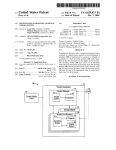
2.2 System Block Diagram
Figure 1. Block Diagram of System
http://seniordesign.ee.nd.edu/2010/Design%20Teams/Empowerment/Welcome.html
EMPOWERMENT:
FINAL DOCUMENTATION
PAGE 10
2.3 Generation Description
Figure 2: Generation Subsystem
2.3.1 Wind Power Generation
Current developments in wind generation have resulted in a progressive increase in
rotor size, resulting in growing and prohibitive initial cost. Since our primary focus is
low-cost, not high-efficiency, we'll instead build a low-tech wind turbine to harness the
wind. Our wind turbine has three components: blades, nacelle, and structure.
Blades: We managed to acquire a set of blades manufactured by Southwest Windpower
for the Air-X design from the ND AME Department that were left over from a previous
senior design project. We then bolted the blades to a wooden hub and attached the hub
to shaft using two flange bearings.
Nacelle: The nacelle consists of the pulley system connecting the spinning hub to the
generator. The rotor and alternator will be connected using a drive pulley with the
proper gear ratio to step up the wind speed to the RPM needed for the car alternator.
It's theoretically possible to salvage the pulley and belt from an abandoned automobile,
and a pulley system is considerably less expensive than a gearbox. For our purpose,
we'll be using aluminum V belts and pulleys to avoid corrosion and stress fractures.
To generate electricity, the kinetic source (blades) will drive electric machinery to
induce current flow through our charging circuit. The technologies available to us are
bike dynamos, DC generators, and car alternators. A DC generator is the most obvious
choice for a wind turbine, since it provides direct current that does not need to be
rectified to charge a battery. However, DC generators are not readily available in thirdworld communities. Bicycle dynamos are more plentiful and generally cheaper to
obtain. When building his windmill, William Kamkwamba used a bike dynamo
purchased under the sponsorship of a village chief. The main downside with bike
dynamos is that they usually only generate a few watts of power.
Our best option is using a car alternator for generation. All automobiles built after the
http://seniordesign.ee.nd.edu/2010/Design%20Teams/Empowerment/Welcome.html
EMPOWERMENT:
FINAL DOCUMENTATION
PAGE 11
1960s use alternators with build-in rectifiers and regulators. This means if we can
provide sufficient RPM to the alternator rotor, the output can immediately be used to
charge a 12V battery. More importantly, car alternators can be salvaged from
abandoned vehicles, potentially making this otherwise expensive component of a wind
turbine free. Even in the famine stricken Malawi, junkyards and landfills can be a
potential gold mine for alternators and other material needed for this project.
Car alternators are rated at 30 to 75 amps. Higher rating alternators need a lot of wind
before their output reaches what is required to charge their rotor field, so they would
not produce any electricity at lower wind. Small alternators (30 to 45 amps) will turn at
lower wind speeds, but will have lower output. For our purpose, the lower power
alternators have the advantage of higher fill factor and lower cost. The make and model
of the alternator is not a significant issue for our situation. We'll be purchasing
whichever car alternator is cheapest with a preference for those with low amperage.
After researching the market for cheap, regulated car generator, we purchased the 10IS
Delco-Remy Alternator (model 7127 AC). Originally used in GM vehicles, it is one of
the cheapest car alternators available in market with build in voltage regulators. It
reaches peak output of 63 Amps at 5000 RPM, but begins output power at 1000 RPM.
We plan to run it at 3000 RPM using 6:1 pulley ratio, which should output 30 Amps at
average wind speeds.
Pulley and Structure: We'll be building the overall structure of the windmill using
plywood. While steel provides a sturdier frame, its scarcity and cost makes it a poor
choice for rural communities. Wood structures can be reasonably replicated in most
poor communities. The blades we are using require a threshold wind speed of 8mph,
which is most easily found at some height off the ground. The blades are are
recommended to be placed at least 7 meters off the ground in an unobstructed area. For
our demo, we could not build a structure quite as large as recommended. Instead we
built a short prototype so that the workings of the nacelle could be more easily
observed. At this low to the ground, threshold wind speeds are hard to find. With
increased height the user will experience better results.
The EmPOWERment prototype turbine is pictured below in Figure 3.
http://seniordesign.ee.nd.edu/2010/Design%20Teams/Empowerment/Welcome.html
EMPOWERMENT:
FINAL DOCUMENTATION
PAGE 12
Figure 3: Completed Turbine
2.3.2 Solar Power Generation
After shopping online for appropriate panels, we concluded that most solar panels are
too expensive to fit within our budget. We contacted Professor Curt Freeland in the
CSE department who has a number of donated Koekraf 20W solar panels that he is not
currently using. We are borrowing two 20W panels for this project. The voltage at
rated power is 17V, and the open circuit voltage is 22V. The current at rated power is
1.15A.
Throughout the day and throughout the year, the angle of the sun’s rays changes. To
allow the user to adjust the solar panels for optimal power production, the
EmPOWERment prototype includes wooden stands for the two panels. The stands
have an adjustable angle and allow the user to prop the stands up off the ground. They
are pictured below in Figures 4 and 5.
http://seniordesign.ee.nd.edu/2010/Design%20Teams/Empowerment/Welcome.html
EMPOWERMENT:
FINAL DOCUMENTATION
PAGE 13
Figure 4: Stand Side View
Figure 5: Stand Front View
2.3.3 Power Generation Testing
It is important to know what kind of power the system will produce under various
conditions. To a certain extent we tried to conduct performance testing outside using
real wind and solar energy. We also needed to conduct testing under more controlled
circumstances. To investigate the production levels of the wind turbine, in the fall we
connected a 550-rpm motor to the alternator. The motor imitated wind speed, allowing
us to determine whether the pulley system we had decided on would be sufficient to
drive the alternator. To test the solar panels, we measured the voltage across the
terminals when the panels were in full sun. We then connected the panels to a slightly
discharged battery to measure the voltage and current being provided by the panels.
Our results backed up the Koekraf technical specifications.
http://seniordesign.ee.nd.edu/2010/Design%20Teams/Empowerment/Welcome.html
EMPOWERMENT:
FINAL DOCUMENTATION
PAGE 14
2.4 Monitoring and Control
Figure 6: Monitoring Subsystem
2.4.1 Microcontroller: We are using the PIC18F4620 by Microchip. This microcontroller
uses flash memory, has 64kBytes of memory, 36 I/O pins, 10-bit A/D, and SPI ability.
It has a total of 44 pins, making it simpler to solder than more complicated
microcontrollers. This microcontroller runs at 5V, so we have decided to run the entire
board that houses the microcontroller at 5V. The battery powers the board, which is
12V. The following table outlines each pin connection.
Table 1: Microcontroller Connections
Pin
A0
A1
A2
A3
A4
A5
A6
Type
A/D Input
A/D Input
A/D Input
A/D Input
TTL Output
TTL Output
Ext OSC
A7
Ext Osc
B0
B1
TTL Output
Digital Output
Function
Reading from the wind current sensor
Reading from the solar current sensor
Reading from the load current sensor
Reading from the battery voltage
Output to wind relay
Output to solar relay
Connected to external 20 MHz crystal
osc.
Connected to external 20 MHz crystal
osc.
Output to load relay
SPI SS for the SD card (through level
shift.)
http://seniordesign.ee.nd.edu/2010/Design%20Teams/Empowerment/Welcome.html
EMPOWERMENT:
FINAL DOCUMENTATION
PAGE 15
B2
B3
B4
B5
B6
B7
C0
C1
C2
C3
C4
C5
C6
C7
D0
D1
D2
D3
D4
D5
D6
D7
E0
E1
E2
E3
Vss
Vdd
Digital Output
Digital Output
Unimplemented
Unimplemented
Programmer
Programmer
Digital Input
Unimplemented
Unimplemented
Digital Output
Digital Input
Digital Output
Unimplemented
Unimplemented
Unimplemented
Unimplemented
Unimplemented
Unimplemented
Unimplemented
Unimplemented
Unimplemented
Unimplemented
Unimplemented
Unimplemented
Unimplemented
MCLR input
GND
+5V
SPI SS for the RTCLK
SPI SS for the LCD
ICSP programmer to Melabs programer
ICSP programmer to Melabs programer
Input to timer1, turbine rotation counter
SPI CLK signal
MISO, SPI input to the microcontroller
MOSI, SPI output to the slaves
Parallel display
Parallel display
Parallel display
Parallel display
Parallel display
Parallel display
Parallel display
Parallel display
Parallel display
Parallel display
Master Clear Signal
Ground reference voltage
High reference voltage and power
supply
The pin assignment for the analog to digital conversion dictated for the most part the
parameters for assigning the other pins. The first 4 AD channels are correspond to pins
A[0-3], and since AD pins must be continuous as determined by the AD configuration
register these pins were used for the current sensors and the voltage measurement.
Pin Assignments: AD conversion
Since our measurements are not time critical, the largest parameters for AD conversion
time and time division were used in the AD configuration register. Using these
parameters minimized noise in the readings. For the current sensor readings, when
accuracy depended on the lower bits of the AD output register, we implemented a
quasi twenty-bin FIR digital filter that averaged the signal through 20 iterations. The
http://seniordesign.ee.nd.edu/2010/Design%20Teams/Empowerment/Welcome.html
EMPOWERMENT:
FINAL DOCUMENTATION
PAGE 16
signal was then translated and scaled into a signed short in order to be able to detect
negative currents, making use of the sensor’s wide range.
Since a high resistance voltage divider was used, the signal tended to be more stable for
the voltage sensor; accordingly the digital filter was unnecessary.
Pin Assignments: Relays
Consecutive pins were chosen for controlling the relays in order to achieve consistency
in the design. Setting the tristate of the corresponding pins to 0, we set these pins as
outputs. Changing the value store in the latch associated with each pin changes the
value of the port.
Pin Assignments: SPI
There are six pins associated with the Serial Peripheral Interface to the LCD, SD card
and real time clock (RTCLK). Three signals are shared by all devices: the clock signal
from pin C3, master input slave output (MISO) in C4, and the master output slave input
(MOSI) in C5. All the devices connected in the SPI interface see these three signals, but
only become transparent when the slave select pin is set to the correct position in the
slave. Each slave device is connected to an individual slave select in the microcontroller.
The default settings for each device differ; accordingly, the code changes the
configuration of the master synchronous serial port (MSSP) every time it interfaces with
a different device.
Since the LCD has the lowest clock operation speed, a maximum of 400 kHz, we chose
the slowest setting for the microcontroller clock speed. By using the microcontroller
with the internal oscillator at 125kHz, and configuring the tuning and oscillator
registers, we ensured optimal operation of the display. Furthermore, in the MSSP
configuration register we divided the Fosc by 64 to make a 2 kHz SPI clock speed. Since
our application is not time sensitive these settings are appropriate. The LCD slave select
needs to be cleared in order to make the SPI signals transparent to this device. For the
other two devices the slave select must be 1.
Pin Assignments: Rotation Sensor
Pin C0 was selected to be the input of the Hall effect sensor, because it is already
connected in hardware to the timer1 counter registers. Using the timer1 configuration
registers, timer1 was set to be fed from an external input, and to have a 1:1 scale factor.
Timer0 was set to increment with a frequency of Fosc divided by 64. Accordingly, the
initial value after each counter overload is set to be 2000 counts less than the full
register. In other words, since it takes 2000 oscillations for the timer0 register to
overflow starting the interrupt routine that calculates the rotational speed of the
turbine, the register is set to 2000 counts less than the full value of the register. This
ensures that the counter sec in the code increments every second.
http://seniordesign.ee.nd.edu/2010/Design%20Teams/Empowerment/Welcome.html
EMPOWERMENT:
FINAL DOCUMENTATION
PAGE 17
2.4.2 Hardware: Sensors
Current: We are not anticipating having any current much higher than 30A, but the
alternator has the ability to produce up to 70A if driven too hard. To provide for that
case, we made sure to use current sensors with a wide range. We decided on a Tamura
Hall Effect current sensor that can measure +/- 100A. Figure 7 shows the sensor range.
Figure 8 is a schematic of the sensor; VCC in Figure 7 is 5V. We are running the power
wires through the hole in the current sensors, and the sensor measures the current
flowing in the wire. The sensor outputs the current measurement as a voltage between
1V-4V on pin 4, as shown in the diagram below. 2.5V corresponds to 0A, and each +/.1V corresponds to +/-10A.
Figure 7: Current Sensor Characteristics
Figure 8. Current Sensor Diagram
The output of the sensors is run through unity gain buffers made from op-amps. This is
in order to guarantee signal integrity, particularly since the signal had to travel from the
sensor boards to the main board. These sensors have a wider range than our expected
currents. This might seem as a disadvantage, however it makes the system more
versatile by allowing more powerful wind and solar generators to be connected to the
system.
Our system has three separate yet identical current sensor boards, one for the wind
cable, solar cable, and cable delivering power to the load. We decided to place each
sensor onto its own board to make spacing and wiring within our central system box
simpler. The wire carrying the power from the wind turbine and to the load is 10
gauge, making maneuvering difficult. Keeping the boards modular makes the
arrangements within the box possible.
Voltage: The voltage sensor uses a 100 k Ohm and 47 k Ohm voltage divider. This allows
for a sensing range from 16 to 0 volts, which correspond to 5 and 0 volts output voltages
respectively. The high resistance makes power dissipation minimal. Higher resistances
however might not provide enough current to the AD converter to work effectively. A
future improvement for this system could be a unity buffer between the voltage divider
http://seniordesign.ee.nd.edu/2010/Design%20Teams/Empowerment/Welcome.html
EMPOWERMENT:
FINAL DOCUMENTATION
PAGE 18
and the microcontroller. However, since the variance of this signal is so low and the
impedance of this channel so high the current implementation works fine.
RPM: To record wind speeds and rotor speed, we ordered an Infineon Hall effect
Sensor. This sensor requires 5V to operate. The alternator cannot consistently power
the sensor because when the relay is off, the alternator will not produce voltage. We
would like to measure RPM continuously, not just when we are charging the battery
with the energy produced by the turbine. Particularly, the sensor helps to establish if
the turbine is rotating above a threshold of minimum RPMs before powering the coils of
the alternator. This helps the turbine reach an optimal rotational speed before powering
the coils in the alternator. We plan to wire 5V, a GND, and a signal wire out from the
microcontroller board to the Hall effect sensor board. The hall effect sensor board will
be located out at the wind turbine.
We used a Schmitt triggered unipolar Hall effect sensor that responded only to the
presence of a north pole. The Schmitt trigger reduced the amount of noise in the output,
and prevented false-positives. The output of the sensor was an open drain connected to
a unity gain buffer that ensured signal integrity for the long journey to the system.
We have secured a powerful magnet, 1800 gauss, to a blade of the turbine. The Hall
effect sensor is mounted on a 1 inch2 board close to the rotor, so during each revolution
the magnet passes close to the sensor. Every time a magnet passes by the sensor, the
sensor triggers.
Testing Plan: The current and voltage sensing systems can be verified by using a
functional multimeter to double check the found values. The Hall effect sensor can be
checked by using a strobe light to measure the win turbine RPM.
2.4.3 Hardware: LCD Display/User Interface We are using an LCD screen with an SPI
Interface from Newhaven Displays. The screen has optional colored LED backlights
and runs at 5V, which is convenient for our board design. Our board includes the
capability to also run a parallel LCD. We left both options open, but ultimately decided
on SPI for our final prototype because it uses fewer pins. The simpler design was
attractive.
We considered including buttons to allow the user more interaction with the system. In
the end we did not include buttons because we wanted to keep the system simple. The
added user involvement seemed unnecessary given the philosophy behind our project.
http://seniordesign.ee.nd.edu/2010/Design%20Teams/Empowerment/Welcome.html
EMPOWERMENT:
FINAL DOCUMENTATION
PAGE 19
Figure 9: LCD Display
Testing Plan: We will display the values read from the sensors on the LCD screen.
Because the LCD displays only two lines at a time, the display will cycle through the
information.
2.4.4 Hardware: Data Storage
While it is nice for the users to see in real time the electric production and consumption
of their EmPOWERment system from the LCD display, the data will be lost without
having a storage option available to the microcontroller. If a storage option is available,
the data collected by the various sensors can be analyzed at a later date and evaluated
over a longer time range without the limitations inherent to a microprocessor system.
This benefit leads us to look into storage options that are available to us, and we
determined that the Secure Digital Card (SD Card) storage format is the best option for
our project.
As the most popular storage medium for consumer gadgets such as cameras, phones,
and music players, the SD Card offers a low cost, high capacity, and wide availability
option for data storage. Furthermore, the SD protocol is widely documented and offers
compatibility with the comparably simple SPI protocol. We also benefit from the fact
that our microprocessor has an MSSP module that has a hardware implementation SPI
protocol, which further reduces the software overhead required for storage.
Our controller receives data streams from six one-byte analog sensors, one two-byte
RPM sensor, and three sets of relay control. Therefore our controller generates data at
the maximum rate of about 150 bytes a second, or about 13 MB a day. We expect the
longest period we will collect to be no more than a month, thus a 512 MB SD Card
should be more than sufficient for our usage.
In order for the data we collect to be usable, we have to choose a file system that can be
read on a personal computer. We chose the FAT format since Windows, Macintosh,
and Linux OS support it. As an older file system, it is simpler to implement due to the
http://seniordesign.ee.nd.edu/2010/Design%20Teams/Empowerment/Welcome.html
EMPOWERMENT:
FINAL DOCUMENTATION
PAGE 20
lack of modern error correction system. Since our data are not critical in nature, that is
not a major issue, and the time saved can be utilized elsewhere to improve our project.
Since the SD card runs at 3.3V and the rest of the system logic runs at 5V, we had to
implement a 3.3V voltage regulator, and a voltage level shifter. The voltage regulator
was placed in cascade after the 5V regulator. This ensures that the input voltage is
above the minimum threshold specified by the LD1117 3.3 regulator. It also ensures that
the 3.3V regulator is protected by the 5V regulator. The Maxim3378 level shifter fit our
needs with a 5 line conversion: one for the slave select, one for the clock, one for the
MISO, and one for the MOSI. Since the SPI clock signal was at its lowest speed, and the
level shifter had a wide range of operational frequencies, speed was not an issue.
A real time clock was included in the design primarily to aid in data collection. The real
time clock works by receiving the oscillator frequency from a 33 MHz external ceramic
resonator. It interfaces with the microcontroller through the SPI interface. However, not
all of the functions of the RTCLK were implemented. Particularly, the it has alarms
which can set interrupts and change certain pins that can be connected in the
microcontroller. These could have been used to get the sunset and sunrise time in the
microcontroller code. However, the current implementation is more efficient with
regards to the pin distribution; furthermore, it allows a function to calculate the sunrise
and sunset times depending on the time of the month. We fixed two mistakes in the
schematics Vbat, the input voltage for a support battery, and Vdd2 were both
grounded. They were previously left unconnected and connected to Vdd respectively.
In the prototype we fixed these problems by severing the copper lines, and routing the
pins to the ground using a thin wire.
2.4.5 Software
The software interfaces with the user in both English and Spanish, extending the range
of locations where our system can be deployed. Other languages that can easily be
implemented include French, Portuguese, and Quechua, reaching 1.5 billion people all
around the globe
The software was developed in separate libraries that contained functions for the
different subsystems. These libraries include: an SPI LCD library based on the parallel
LCD library provided by Dr. Schafer, a RTCLK library, a relay library, an analog to
digital conversion library to handle the current sensors and the voltage sensor, and a
rotation sensor library. All of these libraries include initialization routines for the
different devices. The following is a brief overview of the flow of the code and a
description of the contents of each library. The full body of the software is available in
Appendix B or on the project website.
http://seniordesign.ee.nd.edu/2010/Design%20Teams/Empowerment/Welcome.html
EMPOWERMENT:
FINAL DOCUMENTATION
PAGE 21
Figure 10: Main Code Flow
RTCLK Library
The real time clock library defines a time struct that holds all of the data in binary
decimal coding. It has a primordial function writeSPIRTC that writes and reads
characters to the real-time clock. The init function sets the MSSP to the proper
parameters. Write and read functions use a write register function to get and set the
time in the real time clock. A function calculates the sunrise and sunset depending on
the month of the year. These values are based on the global averages available for South
Bend. In future implementations, a user interface using a keyboard could be used to set
the initial time, as well as communicate the latitude where the system is deployed. This
way the system can accurately operate the solar panels only during daytime. GPS could
be another possible addition; however, the price of the system will increase, making it
less accessible to impoverished communities.
http://seniordesign.ee.nd.edu/2010/Design%20Teams/Empowerment/Welcome.html
EMPOWERMENT:
FINAL DOCUMENTATION
PAGE 22
Relay Library
Setting the appropriate port tristates to outputs initializes the relays. The wind relay can
only be turned on when the velocity of the turbine is above 20 rpm. The solar relay can
only operate during daytime. The sunset, sunrise, and current time are passed onto this
function.
A2D Library
The parameters for AD conversion have been previously described. The initialization
function sets the appropriate values in the adcon register. The functions return the
values of the AD conversion after they are translated and re-scaled. The results short
signs; however, these functions print the values of these conversion to a decimal
accuracy.
Figure 11: Interrupt Routine
Rotation Sensor Library
The rotation sensor initializes the interrupt configuration registers and starts the timers:
timer1 and timer0. The actual calculation is performed by the interrupt routine,
pictured above in Figure 11.
http://seniordesign.ee.nd.edu/2010/Design%20Teams/Empowerment/Welcome.html
EMPOWERMENT:
FINAL DOCUMENTATION
PAGE 23
SPI LCD Library
The SPI LCD contains an initialization function that sets the MSSP to the correct
settings. Most of this library was constructed upon the parallel LCD library provided by
Dr. Schafer. There is also a function that reads the time struct pointers. This function
serves to print the current time.
Main code
The main code contains an initialization routine that checks the relays by switching
them on and off, letting the user know that they are operational. The sensors are read,
and depending on the values of current input and output and the voltage of the battery
the system enters into three main states.
1-Battery full
If the battery reaches 14 volts, but the current output is greater than the inputs, it will
turn on the inputs so the battery is not drained. Otherwise the battery can only provide
energy.
2- Battery OK
If the battery voltage is between 14 and 10 volts, all of the relays are on.
3- Battery Discharged
If the battery reaches 10 volts and the inputs are greater than the outputs, the outputs
are connected allowing critical applications to continue working while protecting the
battery from deep discharging. Otherwise the inputs are on and the outputs are off.
Nota bene: there are switches that the user can turn on to bypass the relays. Since this defies the
purpose of the system these switches are only accessible after opening the box.
Power Calculation and Display
The code calculates the power consumed and generated and displays it to the user. It
also displays the speed of the rotor and the current time.
http://seniordesign.ee.nd.edu/2010/Design%20Teams/Empowerment/Welcome.html
EMPOWERMENT:
FINAL DOCUMENTATION
PAGE 24
2.5 Storage
Figure 12: Storage Subsystem
2.5.1 Battery: Because we are looking for a cheap, easy-to-find battery, we are using a
12V lead acid battery. These batteries are very widespread since they are used in many
applications, most notably automobiles. These batteries also prefer to be float-charged,
which is how our system will do most of the charging. During testing, the likelihood of
deep discharge for the battery is very high. With a normal 12V lead acid battery, 5 or 6
deep discharges can irreparably damage the battery. To avoid this we invested in a
deep discharge battery designed for marine applications. Once testing is complete and
the danger for deep discharge has been mostly eliminated, a normal lead acid battery
could be substituted. We have purchased an Xtreme Batteries Plus 12V battery rated at
75 Amp-hours.
We have not fully determined the best method to connect the battery to the rest of the
system. Power cords from the generating subsystem run into the main system box,
where the voltage and current is monitored. Then it is delivered to the battery, which is
housed outside of the main box.
Testing Plan: We would like to investigate the capacity of our battery. The rated
capacity may not reflect the real physical behavior. This will be done by slowly
charging the battery to full charge. Then we will drain the battery at a constant load,
monitoring the current and voltage the entire time. We will time how long it takes the
battery to reach deep discharge. These practices will help us to determine the real
capacity.
2.5.2 Relays:
The main role of the relays is to protect the battery from over- or deep discharging.
These relays are designed for automotive use, so they are well equipped to be switching
http://seniordesign.ee.nd.edu/2010/Design%20Teams/Empowerment/Welcome.html
EMPOWERMENT:
FINAL DOCUMENTATION
PAGE 25
the voltage and current associated with charging a 12V lead acid battery. These relays
are capable of switching 40A, which is higher than our expected current for anywhere
in the system, and operate at voltages up to 12V. It should be noted that the relays are
the component that limit the amount of current the system is able to handle. If this
system is revised to include a more powerful alternator or wind turbine, the relays will
need to be updated. They also have a built-in surge-absorbing diode to protect the relay
from the large EMF that occurs when it is switched into the disconnected position. As
an additional protection, we soldered diodes across the coil terminals of each of the
relays. The packaging is conveniently compact, saving space within our system. We
have chosen the chassis mount model to allow for easy mounting within the system
box. The rated operating current is 117mA, making their operating power consumption
around 1.4W. This power will be consumed when the relays are driven by the
microcontroller. At extremely low battery voltage, the relays will go back to their
default connected position. However, the battery protection built into the inverter
should prevent the user from further damaging the battery.
To drive the relays, we are using Fairchild NDS355AN transistors as switches. One of
the main applications for these transistors is driving relays. For a VGS of 4.5V, they
produce an ID of 1.7A. The relays require 117mA to operate, so this ID is adequate. The
microcontroller will provide the VGS to the FET to then switch the relay. Each
transistor consumes .5W.
The relays are mounted separately from the rest of the components. We made this
decision because we want to keep the wires carrying the main power away from the
board with sensitive components on it, and also for greater flexibility during assembly
We are connecting the relays to the current boards using spade lugs. The connection is
necessary in order for the microcontroller to control the opening and closing of the
relays.
During the testing process we connected the battery using the wrong polarity, which
forced too much current through these protection diodes subsequently destroying
them. As a result we reverted to using unprotected relays to which we soldered some
protection diodes. This incident also led to the disabling of port A5. Accordingly we
had to route port D6 to the solar relay. In order to prevent this from happening in the
future, particularly as our intended clients are not technologically savvy, we placed a
protection diode between the input of the battery to the system and the switch that
turns on the system.
Testing Plan: To test this set-up, set the circuit up so that the relay connects a 12V battery
and the motor. A test program in the microcontroller sends a signal of 0V to the gate of
the driving MOSFET for ten seconds, and then sends a positive signal for 10 seconds,
switching back and forth. If the motor first runs, corresponding to a 0V signal, and
then stops for 10 seconds, corresponding to the positive signal, the relay system is
http://seniordesign.ee.nd.edu/2010/Design%20Teams/Empowerment/Welcome.html
EMPOWERMENT:
FINAL DOCUMENTATION
PAGE 26
working correctly. In the final system, the relays will be triggered if the battery falls
below 10V, goes above 14V, or when the alternator is just starting up.
2.5.3 Switches: In case the user would like to override the microcontroller and the relays,
three manual switches will allow the user connect and disconnect the battery to and
from the generating subsystem and the load. These switches will be connected in
parallel with the relays.
2.6 Load
DC-AC Inverter: Two main types of inverters are available on the market. Modified
sine-wave inverters are an inexpensive option, usually costing $.05-$.10/Watt. This
type of power has a total harmonic distortion (THD) of about 25%. A modified sinewave inverter works great for electronics like TV’s, most lights, microwaves, and many
tools. However, modified sine-wave inverters are unsuitable for sensitive electronics
like computers, stereo equipment, some kinds of fluorescent lights, and some medical
equipment. For average home use, a modified sine-wave inverter would suffice. If a
medical center, school, or business wants to use the system to power computers or
medical equipment, though, a pure sine-wave inverter is necessary. Because we are
operating under a small budget, we have decided to purchase a modified sine-wave
inverter for the prototype. If these systems went into production, emPOWERment
would most likely offer two product levels, one for home use and one for
office/medical use.
The inverter we have selected is the CPI-480 by Cobra. This inverter has 400W
continuous, with 800W surge. It has two AC outlets for the user to power appliances
with. It has a very low no-load current draw of <.5A. The efficiency is about 88%,
which is fair for its price range. It also has an automatic shutdown at a battery voltage
of 9.5V. Providing 400W to this inverter would require about 30A from the battery. A
fully charged battery with no contribution from the energy generation systems could
provide 400W for about .93 hours. Or, for a more realistic example, the system could
power a 100W 19” color TV for about 3.75 hours.
http://seniordesign.ee.nd.edu/2010/Design%20Teams/Empowerment/Welcome.html
EMPOWERMENT:
FINAL DOCUMENTATION
PAGE 27
Figure 13: Inverter
Pictured above in Figure 13 is the inverter in EmPOWERment’s prototype. The inverter
is mounted underneath the system box, above the battery.
2.7 System Housing and Construction
The main system box is a 10”x6”x3” Polycase box. This design was chosen for its large
size and durable material. We cut a rectangular opening in the lid of the box for the
LCD screen to fit through. The seam was weatherproofed with hot glue and covered in
electrical tape for a clean finish. The cover of the box is decorated with a traditional
Colombian design, shown in Figure 14.
http://seniordesign.ee.nd.edu/2010/Design%20Teams/Empowerment/Welcome.html
EMPOWERMENT:
FINAL DOCUMENTATION
PAGE 28
Figure 14: System Box, Top View
One side of the box contains the main connections between the power generation
sources, load, and rotation sensor board. These connections were made by drilling into
the side of the box. The two connectors for the high current carriers, or the positive
wind terminal and the positive load terminal, are aluminum splices from Lowe’s
Hardware. The other connectors are simply metal screws and washers. Figure 15
shows these connections.
Figure 15: System Box Side Connections
The battery connects to the board from below. The system box is designed to sit on a
frame that covers the battery. The prototype frame is made from wood. The power
from the battery connects to the box through an aluminum splice. The negative
terminal of the battery provides the common ground for the entire system, including
the negative terminals of the power generation and the load. All four negative/GND
leads connect to the box from beneath through an aluminum splice. Figure 16 shows
the main system box screwed onto its stand and connected to the battery from below.
http://seniordesign.ee.nd.edu/2010/Design%20Teams/Empowerment/Welcome.html
EMPOWERMENT:
FINAL DOCUMENTATION
PAGE 29
Figure 16: System Box with Stand
The Hall effect sensor board is housed out at the turbine by a recycled Coca-Cola plastic
bottle. The original polycase box we ordered for the housing interfered with the sensors
detection abilities, so we got creative. The thin plastic housing is secured to a piece of
balsa wood using a variety of adhesives.
All connectors in the side of the box were weatherproofed with hot glue. They were
also labeled and color-coded for the user. All connections were made with either Molex
connectors or crimp-on spade lugs that were then protected with heat shrink and
electrical tape, depending on what materials were available during the time of
construction.
3 SYSTEM INTEGRATION
3.1 Testing Methods
Testing procedures for individual components are included in the previous section as
each component is described. When putting the entire system together, we started
slowly, adding one component at a time until the system was complete.
Our first steps in testing centered around making sure our newly soldered boards
functioned as we expected. Initially we verified that our microcontroller and main
board was working. We did this by running a test program that displayed various test
values on the SPI LCD. Next we verified that the current sensor boards were
functioning by running wires with test currents through them and displaying the
output with the microcontroller and LCD. We double-checked the values found using
an ammeter. The next step was adding the relays to the circuitry and making sure the
microcontroller could control them. We simulated threshold battery voltage readings in
http://seniordesign.ee.nd.edu/2010/Design%20Teams/Empowerment/Welcome.html
EMPOWERMENT:
FINAL DOCUMENTATION
PAGE 30
the test code, and the relays opened and closed accordingly. Finally, we connected our
Hall effect sensor board to the main board and simulated the blades rotating by moving
a magnet across the sensor. The SPI LCD reported an approximate rpm for the
movement of the magnet.
Next we made sure our power sources were functioning. We had previously checked
the solar panels in the sun, and we knew that the panels’ performance followed the
technical specifications. We had checked the alternator’s performance in the fall demo
and knew that if the alternator could reach its threshold rpm it would produce
electricity. We could not simulate threshold wind speeds in the Learning Center or find
threshold wind speeds reliably outside, so we had difficulty testing the effectiveness of
the turbine. On the day of the demo the turbine reached high speeds and succeeded in
producing electricity, so we verified that with suitable wind speeds the system is fully
functional.
With the circuitry fully working and the power sources producing electricity, we had
great confidence in the functionality of the system. At this point we connected the
inverter to the system, and then connected an AC load. The load drew current,
displayed both by the LCD and the fact that the speaker system we had plugged in was
playing music. Our testing was complete.
3.2 Fulfilling Requirements
The finished prototype met most of the initial requirements. At full wind and sun, the
system produces 400W. The power produced by the power generation sources charges
the battery. The monitoring system protects the life of the battery through the use of
voltage detection and relays. The monitoring system also provides vital system
information to the user in both English and Spanish. Both DC and AC output are
available to the user, allowing the user to power a wide variety of useful devices.
The entire system is simple, and it is made from easily found and replaceable
components. For example, the wind turbine is made primarily from wood, with the
inner workings of the nacelle being constructed from a car alternator and a system of
pulleys instead of harder to find DC generators or a fixed gear system. 20W solar
panels are becoming increasingly popular and easy to find, even in developing
countries. Many solar panels can be found in developing countries, like Kenya and
India, which have been made locally, thereby dropping the price. The system remained
very modular, allowing the user to substitute in various power sources, battery types,
and inverter models.
One goal we did not meet was the use of an SD card. Our main board has the hardware
and connections necessary to at some point accommodate an SD card. EmPOWERment
could not finalize the necessary software to store the information being gathered by the
microcontroller. The final system box layout allows for access to the programmer
http://seniordesign.ee.nd.edu/2010/Design%20Teams/Empowerment/Welcome.html
EMPOWERMENT:
FINAL DOCUMENTATION
PAGE 31
pinheader so that the microcontroller could at some point be updated to use the SD
card.
4 USER’S MANUAL
At its most basic level, the final system that would be ready for distribution would
consist of the main system box with an inverter. The user would be responsible for
supplying the power sources, the 12V battery, and all appliances. As the organization
expands, more products would become available. For example, once it optimized a
design, EmPOWERment could start manufacturing small-scale wind turbines for use
with the systems. Alternately, EmPOWERment could sell photovoltaic cells or
batteries. Initially though, or at least until EmPOWERment could provide the elements
more cost effectively than the user could, EmPOWERment would provide only the
system box and encourage the user to find all other elements locally.
4.1 System Installation and Set-Up
4.1.1 Additional Hardware Selection
The system can take up to two power sources. Each power source needs to provide at
least 12V-DC for effective charging of the battery. The power source should not
provide more than 17V-DC. Too large of a voltage difference between the sources and
the battery could harm the battery, while too little of a voltage difference will take a
very long time to charge the battery. The power sources should also ideally be
regulated to protect the battery and the system.
The EmPOWERment prototype made use of two types of power generation, namely
two photovoltaic cells connected in parallel and a homemade wind turbine.
EmPOWERment recommends a similar set-up if possible. Using two power generation
sources greatly increases the capacity and improves the overall performance of the
system. Choosing the location for both wind turbines and solar panels is an important
decision. Placing these generation sources in areas that receive ample sun and wind is
key. Spend time considering the area available before breaking ground on any
construction.
The system is designed to charge a standard 12V lead acid battery. Lead Acid is ideal
because the embedded intelligence is designed to follow ideal lead acid charging
behavior. Other 12V battery types will function, but the system might not be as
effective at preserving battery life.
4.1.2 Connections
For visual reference, turn to Figure 15 on page 28.
When connecting the output of the power generation sources to the system box, make
sure to use an appropriately gauged wire. This will depend on the amount of current
each source is anticipated to produce. In general, DC current requires a thicker gauge
than AC current. In the EmPOWERment prototype, the wind turbine produces around
http://seniordesign.ee.nd.edu/2010/Design%20Teams/Empowerment/Welcome.html
EMPOWERMENT:
FINAL DOCUMENTATION
PAGE 32
30 Amps at average wind. The connection between the alternator in the turbine and the
system box was made with 10 gauge wire. The solar panels, on the other hand, produce
only 1.5 Amps, so their connection was made with 10 gauge wire. To connect the
power sources to the system box, connect one end of an appropriately sized wire to the
positive output of the power source, and then insert one stripped end into one of the
power source screw terminals and firmly secure using a flat-edge screwdriver. Connect
another wire of the same size to the negative output of the power source and connect
the other stripped end to the common ground screw terminal located on the underside
of the system box. Repeat these steps for the other power source.
The EmPOWERment prototype wind turbine had a Hall Effect Rotation Sensor installed
in order to measure wind speeds. The sensor receives power from the main
microcontroller board, and the signal from the sensor needs to be relayed back to the
board. To connect the sensor to the main board, use three small wires, ideally colorcoded red (power), black (ground), and white (signal). Connect one end of the wires to
a Molex 3-pin connector. The Molex connector latches to a matching piece on the Hall
Effect Sensor board. Run the wire back to the system box and insert the appropriate
stripped wire into the three provided screw terminals.
The positive lead from the inverter is color-coded red. It connects to the screw terminal
labeled “Load” on the connection panel of the system box. The negative lead is colorcoded black, and it connects to the common ground screw terminal located on the
underside of the system box.
The connections between the battery and the system box occur on the underside of the
box. Use a thick gauge wire to be safe. Connect the positive terminal of the battery to
the screw terminal color-coded red. Connect the negative terminal to the other screw
terminal. The polarity of the battery is very important; avoid wiring in the connections
to the battery backwards. Also take care to not short the battery, i.e. connecting the
negative directly to the positive terminal. This is dangerous and harmful to the battery.
It is recommended to connect the battery last. Once the battery is connected, the system
should begin to operate. The system box should arrive fully assembled and ready to
run as soon as all external connections are made.
4.2 Everyday Use
Once the external connections are made, the system is designed to continue to run
without repeated disconnections and connections. The LCD displays important
information to the user at all times. The microcontroller and relays control connections
between the battery, power sources, and load. Switches inside the system box exist as a
last resort for extreme circumstances.
The display cycles continuously through a set of important information in both English
and Spanish. The LCD displays the speed of the turbine blades, the power generated
http://seniordesign.ee.nd.edu/2010/Design%20Teams/Empowerment/Welcome.html
EMPOWERMENT:
FINAL DOCUMENTATION
PAGE 33
by the turbine, the power generated by the solar panels, the power consumed by the
load, the remaining charge on the battery, and the date and time.
By checking the LCD, users can keep track of the average power output of their system.
If a user checks consistently, then the user will notice quickly if the system is producing
less power than usual. The user can then promptly visit the power production sources
and perform maintenance or adjust position as necessary.
Checking the LCD often can also aid users in taking care of their battery. For example,
the display shows how much power different loads draw. A user can then budget their
battery life better, perhaps choosing to use a light for four hours instead of a power
intensive refrigerator for only two, depending on the initial battery charge. Familiarity
with usual battery life can also help a user to identify when a battery has reached the
end of its life and needs to be replaced.
The included inverter is ideal for any appliances requiring AC power. The inverter
included in the EmPOWERment prototype takes US plugs. However, the inverter
could easily be changed to be appropriate for whatever plugs are common to the user.
For appliances requiring DC power, the battery terminals remain exposed for easy
access. A simple set of leads from the positive and negative terminals of the battery
would be easy to build if DC appliances are common for this user.
4.3 Troubleshooting
In general, if any component in the system quits working, double-check all connections.
The system is designed to spread over a long distance connected only by wires, and it is
very likely that wires will become worked loose over time. Re-screwing wires and
checking connections will most likely go a long way in trouble-shooting any problems.
The rest of these troubleshooting tips assume that all connections have been secured.
If the LCD shows that one or both of the power sources is not producing energy when
they clearly should be (i.e., turbine turning, bright sunshine), or the load is not
consuming energy when it clearly is, check the energy production sources and the loads
themselves. If the sources appear to be in good working order, the problem could lie
within the system box. For example, the current sensor or microcontroller pin reading
the sensor could have broken. If this is the case, the system should continue to charge
the battery. The system will simply cease to display generation statistics for that power
source. The user should verify that the battery continues to appear charged over a
period of days.
The LCD refusing to light up could indicate either that the LCD is broken or that the
entire microcontroller and circuit is broken. One way to check is to first disconnect the
battery and open up the system box. Reconnect the battery and listen for the clicking of
the relays initializing. If the relays click, then only the LCD is broken and the rest of the
circuitry is working. The system remains operable, if a little inconvenient to use. If the
http://seniordesign.ee.nd.edu/2010/Design%20Teams/Empowerment/Welcome.html
EMPOWERMENT:
FINAL DOCUMENTATION
PAGE 34
relays are silent, then the entire board is likely broken. In this case, the user may
continue to use the system by manually connecting and disconnecting the switches
connecting the battery to the power sources and the load.
If the user notices the battery refusing to hold a charge, it could be time to reinvest in a
new battery. Batteries have a finite lifetime and will likely need to be replaced many
times over the lifetime of the system. If the user notices the power sources producing
poorly, the user should reanalyze the locations of the sources, or perhaps consider
upgrading to a higher efficiency solar panel or more sophisticated turbine design.
5 CONCLUSIONS
5.1 Results
Overall, we are pleased with the results of our system. By the final demo the system
met all of the initial requirements except for data storage capability, and that capability
remains a possibility for the future. At the demo all aspects of the project performed
smoothly. The only aspect of the demo that could have been improved was wind
speeds. Because our prototype turbine was so low to the ground, very high wind
speeds are required to start the alternator. The wind speeds were not often high
enough to generate electricity. The wind was often strong enough to turn the blades
without the alternator, and at one point was strong enough to turn the alternator.
5.2 Future
While we are pleased with the system’s performance, there is plenty of room for
improvement in our design. If we had another year to modify the prototype, we would
likely start with implementing the SD Card, improve the user interface, optimize
turbine design, and refine the business model of the system.
Our original goal of using the SD card to store power generation and usage data
remains. Analysis of that stored data is invaluable in optimizing the system. After
installing the SD card, we would ideally like to start some sort of long term testing
procedure to gather data over a period of weeks. This data would also help us
determine the overall usefulness of the system.
The way our system works now, the LCD scrolls constantly whenever the battery is
connected. This is a drain of energy. With an improved prototype, we would look into
adding buttons or a switch to turn the display on instead of having it on all the time.
With the added feature of buttons, the user interface could also become more
interactive. Users could select the value the want to view instead of waiting for it to
scroll through. With buttons the user could also reset the time and date of the real time
clock.
Throughout the design process, we debated how technologically advanced to make the
system. With greater complexity comes better performance, but also increased cost and
http://seniordesign.ee.nd.edu/2010/Design%20Teams/Empowerment/Welcome.html
EMPOWERMENT:
FINAL DOCUMENTATION
PAGE 35
greater chance of failure later on. However, one technical improvement whose
advantage could outweigh the risk is adding a GPS unit to the system. A GPS system
could calculate the sunrise and sunset times for any location in the world. The sunrise
and sunset times in the prototype are hardcoded for South Bend, IN. GPS capability
adds to the flexibility of the system. Another possible improvement is adding Zigbee
communication between the microcontroller and the rotation sensor in order to
minimize long, inconvenient wires stretching between the two systems. A power cable
will always be necessary, but reducing the number of wires could be convenient.
Our turbine as we built it is fairly primitive. It sits low to the ground and does not
rotate in order to always be facing the wind. We also decided to use manufactured
blades in order to save time. A second prototype would include a second approach to
building a turbine that is taller, that rotates, that produces at lower wind speeds, and
that uses hand-made blades instead of manufactured blades.
One of the things that got us the most excited about this project is the possibility of
refining the system and distributing it. The current prototype is far from being ready to
be manufactured or distributed, though. In addition to technical questions remaining
unanswered, there are many business-side decisions still to be made. For example,
while we have a general idea of what EmPOWERment would theoretically distribute,
the total system components have not been finalized. Perhaps it would make more
sense to sell the system box along with the power generation sources and a battery.
Our thoughts now are that users would be resourceful enough to find the remaining
components if they could only buy the system box, but perhaps the convenience of
buying a complete system would outweigh any cost savings. Determining what a
complete system would consist of is key before nailing down a cost estimate. Figuring
out the financials also involves deciding how the systems would be manufactured.
Another major missing piece of the plan is how the systems would be sold and
distributed. Before being pursued seriously, the venture would need to have solid
financial predictions and a possible plan for distribution.
Even with all of these unanswered questions, we think that we have come a long way
this semester toward reaching a tangible solution. The project has a lot of potential and
possibility for another group of students, either as a senior design project or simply an
independent research project. We hope that the work continues on, and that at some
point this project contributes to empowering homes around the world.
http://seniordesign.ee.nd.edu/2010/Design%20Teams/Empowerment/Welcome.html
EMPOWERMENT:
FINAL DOCUMENTATION
PAGE 36
APPENDIX A: SCHEMATICS AND BOARD LAYOUTS
Note: Full Eagle Files and Libraries included on project website.
A1. Main Board Schematic:
http://seniordesign.ee.nd.edu/2010/Design%20Teams/Empowerment/Welcome.html
EMPOWERMENT:
FINAL DOCUMENTATION
PAGE 37
A2. Main Board Layout:
http://seniordesign.ee.nd.edu/2010/Design%20Teams/Empowerment/Welcome.html
EMPOWERMENT:
FINAL DOCUMENTATION
PAGE 38
A3. Sensor Board Schematic:
http://seniordesign.ee.nd.edu/2010/Design%20Teams/Empowerment/Welcome.html
EMPOWERMENT:
FINAL DOCUMENTATION
PAGE 39
A4. Sensor Board Layout:
http://seniordesign.ee.nd.edu/2010/Design%20Teams/Empowerment/Welcome.html
EMPOWERMENT:
FINAL DOCUMENTATION
PAGE 40
A5. Hall Effect Board Schematic:
http://seniordesign.ee.nd.edu/2010/Design%20Teams/Empowerment/Welcome.html
EMPOWERMENT:
FINAL DOCUMENTATION
PAGE 41
A6. Hall Effect Sensor Board Layout:
http://seniordesign.ee.nd.edu/2010/Design%20Teams/Empowerment/Welcome.html
EMPOWERMENT:
FINAL DOCUMENTATION
PAGE 42
APPENDIX B: SOFTWARE
Note: All Software is also available on the project website.
B1: A2D.h
#ifndef _A2D_H_
#define _A2D_H_
#include <system.h>
#include <memory.h>
unsigned short adre@ADRESL;
unsigned short a2dRead(void);
short a2dReadBattery (void);
short a2dReadCSolar (void);
short a2dReadCLoad (void);
short a2dReadCWind (void);
void OscInit (void);
void a2dInit (void);
#endif
B2: A2D.c
#include "A2D.h"
#include "spiLCD.h"
void OscInit (void)
{
osccon = 0b10011110;
osctune = 0;
//125kHz clock
//disable PLL
}
void a2dInit (void)
{
adcon0.ADON = 1;
adcon1.5 = 0;
adcon1.4 = 0;
adcon1.3 = 1;
adcon1.2 = 0;
adcon1.1 = 1;
adcon1.0 = 1;
adcon2.7 = 0;
adcon2.5 = 1;
adcon2.4 = 1;
adcon2.3 = 1;
adcon2.2 = 1;
adcon2.1 = 0;
adcon2.0 = 1;
trisa.0
trisa.1
trisa.2
trisa.3
=
=
=
=
// Ref voltage is ground
// Ref voltage is Vdd
// A[0 .. 3] A2D conversion
//Left justified
// A2D conversion time 20 Tad
// A2D Conversion Clock Fosc/16
1;
1;
1;
1;
http://seniordesign.ee.nd.edu/2010/Design%20Teams/Empowerment/Welcome.html
EMPOWERMENT:
FINAL DOCUMENTATION
PAGE 43
}
short a2dReadBattery (void)
{
short voltage = 0;
short voltagedec =0;
//unsigned
adcon0.5 =
adcon0.4 =
adcon0.3 =
adcon0.2 =
short high = 0x00ff;
0; // AN3 (A3) pin channel selected
0;
1;
1;
adre = 0;
adcon0.1=1;
while (adcon0.1);
voltage = a2dRead();
voltagedec = voltage;
voltage = (voltage / 61); //only reads out as an integer
spiLCD_printf("Bat/Batt: ");
spiLCD_pos(2);
spiLCD_int(voltage);
spiLCD_printf(".");
voltagedec = ((voltagedec % 61)*100)/61 ;
spiLCD_int(voltagedec);
spiLCD_printf("V ");
return voltage;
}
short a2dReadCSolar (void)
{
char i;
short current = 0;
unsigned short currentdec;
unsigned short sample = 0;
//unsigned short high = 0x00ff;
adcon0.5 = 0; // AN1 (A1) pin channel selected
adcon0.4 = 0;
adcon0.3 = 0;
adcon0.2 = 1;
//Sample 20 times
for(i=0;i<19;i++)
{
adcon0.1=1; // set AD On bit
while (adcon0.1); //While AD is active do nothing
sample += a2dRead();
http://seniordesign.ee.nd.edu/2010/Design%20Teams/Empowerment/Welcome.html
EMPOWERMENT:
FINAL DOCUMENTATION
PAGE 44
}
//Average samples
sample = sample / 20;
spiLCD_printf("Solar Corr/Curr: ");
spiLCD_pos(2);
current = sample - 488;
current = (current)/3;
spiLCD_int(current);
spiLCD_printf(".");
currentdec = ((sample%3)*100)/3;
spiLCD_int(currentdec);
spiLCD_printf("A");
return current;
}
short a2dReadCWind (void)
{
char i;
short current = 0;
unsigned short currentdec;
unsigned short sample = 0;
//unsigned short high = 0x00ff;
adcon0.5 = 0; // AN0 (A0) pin channel selected
adcon0.4 = 0;
adcon0.3 = 0;
adcon0.2 = 0;
//Sample 20 times
for(i=0;i<19;i++)
{
adcon0.1=1; // set AD On bit
while (adcon0.1); //While AD is active do nothing
sample += a2dRead();
}
//Average samples
sample = sample / 20;
spiLCD_printf("Cor. Eolica/Wind:");
spiLCD_pos(2);
current = sample - 485;
current = (current)/3;
spiLCD_int(current);
spiLCD_printf(".");
currentdec = ((sample%3)*100)/3;
spiLCD_int(currentdec);
spiLCD_printf("A");
http://seniordesign.ee.nd.edu/2010/Design%20Teams/Empowerment/Welcome.html
EMPOWERMENT:
FINAL DOCUMENTATION
PAGE 45
return current;
}
short a2dReadCLoad (void)
{
char i;
short current = 0;
unsigned short currentdec;
unsigned short sample = 0;
//unsigned short high = 0x00ff;
adcon0.5 = 0; // AN2 (A2) pin channel selected
adcon0.4 = 0;
adcon0.3 = 1;
adcon0.2 = 0;
//Sample 20 times
for(i=0;i<19;i++)
{
adcon0.1=1; // set AD On bit
while (adcon0.1); //While AD is active do nothing
sample += a2dRead();
}
//Average samples
sample = sample / 20;
spiLCD_printf("Cor. Carga/Load:");
spiLCD_pos(2);
current = sample - 486;
current = (current)/3;
spiLCD_int(current);
//spiLCD_printf(" ");
spiLCD_printf(".");
currentdec = ((sample%3)*100)/3;
spiLCD_int(currentdec);
spiLCD_printf("A");
return current;
}
unsigned short a2dRead(void)
{
unsigned short out = 0;
unsigned short tmp = 0xffff;
tmp &= adresh;
out = ((tmp << 8)| (adresl & 0x00ff));
out = ((out >> 6) & 0x03ff);
return out;
http://seniordesign.ee.nd.edu/2010/Design%20Teams/Empowerment/Welcome.html
EMPOWERMENT:
FINAL DOCUMENTATION
PAGE 46
}
B3: Relay.h
#ifndef _RELAY_H_
#define _RELAY_H_
#include <system.h>
#include <memory.h>
void RelayInit (void);
void RelayWind_on(short);
void RelayWind_off(void);
void RelaySolar_on(unsigned char Sunset, unsigned char Sunrise, struct
CurrentTime *tp);
void RelaySolar_off(void);
void RelayLoad_on(void);
void RelayLoad_off(void);
#endif
B4: Relay.c
#include "Relay.h"
#include "spiLCD.h"
void RelayInit (void)
{
trisa.4 = 0; //wind relay
trisd.6 = 0; //solar relay
trisb.0 = 0; //load relay
RelayWind_off();
RelaySolar_off();
RelayLoad_off();
}
void RelayWind_on(short pmr)
{
if (pmr > 20)
{
lata.4 = 1;
}
else
{
lata.4 = 0;
spiLCD_clear();
spiLCD_printf("Viento");
spiLCD_pos(2);
spiLCD_printf("Insuficiente");
delay_s(1);
spiLCD_clear();
spiLCD_printf("Insufficient");
spiLCD_pos(2);
spiLCD_printf("Wind");
http://seniordesign.ee.nd.edu/2010/Design%20Teams/Empowerment/Welcome.html
EMPOWERMENT:
FINAL DOCUMENTATION
PAGE 47
delay_s(1);
spiLCD_clear();
}
}
void RelayWind_off(void)
{
lata.4 = 0;
}
void RelaySolar_on(unsigned char Sunset, unsigned char Sunrise, struct
CurrentTime *tp)
{
if (CurrentTime->hr >= Sunrise && CurrentTime->hr < Sunset)
{
latd.6 = 1;
spiLCD_clear();
spiLCD_printf("Dia/Day");
spiLCD_pos(2);
spiLCD_printf("Solar ON");
delay_s(1);
}
else
{
latd.6 = 0;
spiLCD_clear();
spiLCD_printf("Night/Noche");
spiLCD_pos(2);
spiLCD_printf("Solar OFF");
delay_s(1);
}
}
void RelaySolar_off(void)
{
latd.6 = 0;
}
void RelayLoad_on(void)
{
latb.0 = 1;
}
void RelayLoad_off(void)
{
latb.0 = 0;
}
B5: RotSens.h
#ifndef _ROTSENS_H_
#define _ROTSENS_H_
#include <system.h>
#include <memory.h>
unsigned short tmr0@TMR0L;
void RotSensInit(void);
#endif
http://seniordesign.ee.nd.edu/2010/Design%20Teams/Empowerment/Welcome.html
EMPOWERMENT:
FINAL DOCUMENTATION
PAGE 48
B6: RotSens.c
#include "RotSens.h"
void RotSensInit(void)
{
//Set the timer to provide an interrupt every second
/* t0con.7 ON turns on Timer0
t0con.6 OFF sets Timer0 as 16-bit timer
t0con.5 OFF to use internal clock0
t0con.4 ON to transit from low-to-high
t0con.3 OFF prescaler is assigned
t0con.2-0 set to 1:64
*/
t0con.7 = 1;
t0con.6 = 0;
t0con.5 = 0;
t0con.4 = 1;
t0con.3 = 0;
t0con.2 = 1;
t0con.1 = 0;
t0con.0 = 1;
// Set C0 to be an input
trisc.0 = 1;
/* t1con
7 16-bit register enabled
6 enables the internal osc
5-4 prescale value 1:1
3 Timer 1 osc enabled
2 External clock synchronize
1 External clock from pin c0
0 Timer 1 on
*/
t1con.7 = 0;
t1con.6 = 0;
t1con.5 = 0;
t1con.4 = 0;
t1con.3 = 0;
t1con.2 = 0;
t1con.1 = 1;
t1con.0 = 1;
0
0
00
0
0
1
1
//Enable interrupts for the microcontroller
//Enable Global Interrupt Enable
intcon.7 = 0b1;
//Enable Timer0 overflow interrupt
intcon.5 = 0b1;
//Preset overflow to 0
intcon.2 = 0b0;
//Peripheral interrupt enabled
intcon.6 = 0b1;
//Timer 1 interrupt disabled
pie1.0
= 0b0;
http://seniordesign.ee.nd.edu/2010/Design%20Teams/Empowerment/Welcome.html
EMPOWERMENT:
FINAL DOCUMENTATION
PAGE 49
//preset tmr0 to 0
tmr0h = 0xFE;
tmr0l = 0x18;
//LCD_printf("data begotten");
tmr1l = 0b00000000;
tmr1h = 0b00000000;
}
B7: RTClib.h
#ifndef _RTCLIB_H_
#define _RTCLIB_H_
#include<system.h>
struct time {
unsigned char sec10;
unsigned char sec1;
unsigned char sec;
// 10s place of seconds
// 1s place of seconds
// Decimal form of seconds
unsigned char min10;
unsigned char min1;
unsigned char min;
// 10s place of minutes
// 1s place of minutes
// Decimal form of minutes
unsigned char hr10;
// 10s place of hours
unsigned char hr1;
unsigned char hr;
unsigned char day;
unsigned char date10;
unsigned char date1;
unsigned char date;
unsigned char mon10;
unsigned char mon1;
unsigned char mon;
unsigned char yr10;
unsigned char yr1;
unsigned char yr;
};
// 1s place of hours
// Decimal form of hours
// Day of the week (Sun=1)
// 10s place of date
// 1s place of the date
// Decimal form of hours
// 10s place of the month
// 1s place of the month
// Decimal form of month
// 10s place of the year
// 1s place of the year
// Decimal form of year
unsigned char writeSPIRTC(unsigned char send);
void RTC_init(void);
char RTC_reg(char add, char input);
http://seniordesign.ee.nd.edu/2010/Design%20Teams/Empowerment/Welcome.html
EMPOWERMENT:
FINAL DOCUMENTATION
PAGE 50
void RTC_set(struct time *tp);
void RTC_get(struct time *tp);
unsigned char cSunrise(unsigned char month);
unsigned char cSunset(unsigned char month);
#endif
B8: RTClib.c
#include <system.h>
#include "RTClib.h"
// Team EmPOWERment recognizes the collaboration from team SmartWindows
// with the developement of this code
#include <system.h>
#include "RTClib.h"
// Global Volatile Bits
volatile bit [email protected];
// Chip Enable
void RTC_init(void){
// Reset
sspcon1 = 0b00000000;
sspstat = 0b00000000;
// SSPCON1
//bit7:
0:
write collision, clear in software
//bit6:
0:
receiver overflow, clear in software, avoid by
always reading buffer
//bit5:
1:
mssp1 enable bit
//bit4:
0:
CKP - idle state is 0 or 1
//bit3-0: 0010: Clock speed - Fos/64
sspcon1 = 0b00100010;
// Sets data in, data out, and clock ports
// BUT: must clear trisc.5 For data out
//
must clear trisc.3 For clock
// I/O Ports
/* Enable:D7 -->
SCK:
C3 -->
MISO: C4 -->
MOSI: C5 -->
trisc &= 11010111b;
trisb.2 = 0;
Output
Output
Input
Output
0
0
1
0
*/
// Set Default Output Values
rtc_en = 0;
// Set chip select high
http://seniordesign.ee.nd.edu/2010/Design%20Teams/Empowerment/Welcome.html
EMPOWERMENT:
FINAL DOCUMENTATION
PAGE 51
// Set up the initial parameters
// Control Register
// Bit 7:
Enable Oscillator (Low True)
// Bit 6:
Write Protect
// Bit 5-3: Reserved
// Bit 2:
Int Con (Use both Int Pins?)
// Bit 1:
Alarm Enable 1
// Bit 0:
Alarm Enable 0
char ans;
ans = RTC_reg(0x8F,0b01000100);
delay_ms(50);
0
1
000
1
0
0
}
unsigned char writeSPIRTC(unsigned char send)
{
//rtc_en = 1;
sspbuf=send;
while(!sspstat.BF);
//rtc_en = 0;
return sspbuf;
}
char RTC_reg(char add, char input){
char output = 0;
rtc_en = 1;
// Set the chip enable low
output = writeSPIRTC(add);
// Send an spi byte with address
output = writeSPIRTC(input); // Send an spi byte with the data/
rtc_en = 0;
// Set the chip enable low
rtc_en = 0;
return output;
}
void RTC_set(struct time* tp) {
char i;
// Loop variable
char ans;
// Temporary register placeholder
char time[7];
// The time information to be sent by SPI
time[0] = ((tp->sec10 <<4) & 0b01110000)
// See datasheet
time[1] = ((tp->min10 <<4) & 0b01110000)
time[2] = ((tp->hr10 <<4) & 0b00110000)
time[3] = tp->day & 0b00001111;
time[4] = ((tp->date10<<4) & 0b00110000)
time[5] = ((tp->mon10 <<4) & 0b00110000)
time[6] = ((tp->yr10 <<4) & 0b11110000)
ans = RTC_reg(0x8F,0b00000100);
rtc_en = 1;
(Burst Mode)
ans = writeSPIRTC(0x80);
for (i=0;i<7;i++) {
ans = writeSPIRTC(time[i]);
automatically)
}
| (tp->sec1
& 0b00001111);
| (tp->min1
| (tp->hr1
& 0b00001111);
& 0b00001111);
| (tp->date1 & 0b00001111);
| (tp->mon1 & 0b00001111);
| (tp->yr1
& 0b00001111);
// Disable write protect
// Send time bytes over SPI
// First address to write to
// Write the 7 bytes (address inc.
http://seniordesign.ee.nd.edu/2010/Design%20Teams/Empowerment/Welcome.html
EMPOWERMENT:
FINAL DOCUMENTATION
PAGE 52
rtc_en = 0;
// End burst mode
ans = RTC_reg(0x8F,0b01000100);
return;
}
// Enable write protect
void RTC_get(struct time* tp) {
char tmp;
// Temporary storage variable
struct time t;
// Structure to hold the output
tmp = RTC_reg(0x00,0);
register
tp->sec10 = (tmp>>4) & 0b00000111;
tp->sec1 = tmp & 0b00001111;
tp->sec
= 10*tp->sec10 + tp->sec1;
tmp = RTC_reg(0x01,0);
register
tp->min10 = (tmp>>4) & 0b00000111;
tp->min1 = tmp & 0b00001111;
tp->min
= 10*tp->min10 + tp->min1;
tmp = RTC_reg(0x02,0);
register
tp->hr10 = (tmp>>4) & 0b00000011;
tp->hr1
= tmp & 0b00001111;
tp->hr
= 10*tp->hr10 + tp->hr1;
tmp = RTC_reg(0x03,0);
register
tp->day
= tmp & 0b00001111;
tmp = RTC_reg(0x04,0);
register
tp->date10 = (tmp>>4) & 0b00000011;
tp->date1 = tmp & 0b00001111;
tp->date
= 10*tp->date10 + tp->date1;
tmp = RTC_reg(0x05,0);
register
tp->mon10 = (tmp>>4) & 0b00000011;
tp->mon1
= tmp & 0b00001111;
tp->mon
= 10*tp->mon10 + tp->mon1;
tmp = RTC_reg(0x06,0);
register
tp->yr10 = (tmp>>4) & 0b00001111;
tp->yr1
= tmp & 0b00001111;
tp->yr
= 10*tp->yr10 + tp->yr1;
return;
}
// Read the seconds
// Decode the 10s place
// Decode the 1s place
// The total seconds
// Read the minutes
// Decode the 10s place
// Decode the 1s place
// The total minutes
// Read the hours
// Decode the 10s place
// Decode the 1s place
// The total hour
// Read the days
// Decode the 1s place
// Read the date
// Decode the 10s place
// Decode the 1s place
// The total date
// Read the month
// Decode the 10s place
// Decode the 1s place
// The total month
// Read the year
// Decode the 10s place
// Decode the 1s place
// The total year
unsigned char cSunrise(unsigned char month)
{
unsigned char Sunrise;
http://seniordesign.ee.nd.edu/2010/Design%20Teams/Empowerment/Welcome.html
EMPOWERMENT:
FINAL DOCUMENTATION
PAGE 53
switch (month)
{
case 1:
Sunrise = 8;
return Sunrise;
case 2:
Sunrise = 8;
return Sunrise;
case 3:
Sunrise = 7;
return Sunrise;
case 4:
Sunrise = 7;
return Sunrise;
case 5:
Sunrise = 6;
return Sunrise;
case 6:
Sunrise = 6;
return Sunrise;
case 7:
Sunrise = 6;
return Sunrise;
case 8:
Sunrise = 6;
return Sunrise;
case 9:
Sunrise = 7;
return Sunrise;
case 10:
Sunrise = 8;
return Sunrise;
case 11:
Sunrise = 7;
return Sunrise;
case 12:
Sunrise = 8;
return Sunrise;
}
}
unsigned char cSunset(unsigned char month)
{
unsigned char Sunset;
switch (month)
{
case 1:
Sunset
return
case 2:
Sunset
return
case 3:
= 18;
Sunset;
= 18;
Sunset;
http://seniordesign.ee.nd.edu/2010/Design%20Teams/Empowerment/Welcome.html
EMPOWERMENT:
FINAL DOCUMENTATION
PAGE 54
case
case
case
case
case
case
case
case
case
Sunset
return
4:
Sunset
return
5:
Sunset
return
6:
Sunset
return
7:
Sunset
return
8:
Sunset
return
9:
Sunset
return
10:
Sunset
return
11:
Sunset
return
12:
Sunset
return
= 19;
Sunset;
= 20;
Sunset;
= 20;
Sunset;
= 21;
Sunset;
= 21;
Sunset;
= 21;
Sunset;
= 20;
Sunset;
= 19;
Sunset;
= 17;
Sunset;
= 17;
Sunset;
}
}
B9: spiLCD.h
#ifndef _SPILCD_H_
#define _SPILCD_H_
#include <system.h>
#include <memory.h>
#include "RTClib.h"
volatile bit [email protected]; // SPI SS LCD
void
etc.
void
void
void
void
void
void
void
void
void
void
spiLCDInit(void); // initializes the SPI LCD MSSP registers trisc, latc
spiLCD_clear(void); //clears spi LCD
spiLCD_pos(unsigned short); // spi LCD carriage return
spiLCD_printf( const char* text ); //sends ascii string to display
spiLCD_int(short dat);
spiLCD_int(char data);
spiLCD_dec(char data);
spiLCD_dec(unsigned short dat);
spiLCD_dec(short dat);
spiLCD_hex(char data);
spiLCD_hex(unsigned short
data);
http://seniordesign.ee.nd.edu/2010/Design%20Teams/Empowerment/Welcome.html
EMPOWERMENT:
FINAL DOCUMENTATION
PAGE 55
void
void
void
void
void
void
void
void
spiLCD_hex(short data);
spiLCD_bin(unsigned short data);
spiLCD_bin(char data);
spiLCD_time(struct time *tp);
spiLCD_shiftL(void); // shift 1 unit
spiLCD_shiftR(void); //shift 1 unit
spiLCD_exitL(void); // message exits
spiLCD_exitR(void); // message exits
to the left
to the right
left
right
unsigned char writeSPILCD(unsigned char);
#endif
B10: spiLCD.c
#include "spiLCD.h"
unsigned char writeSPILCD(unsigned char send)
{
LCDen = 0;
sspbuf=send;
while(!sspstat.BF);
LCDen = 1;
return sspbuf;
}
void spiLCDInit(void)
{
sspcon1.SSPEN=0;
sspstat = 0b00000000;
active)
sspcon1 = 0b00010010;
clock FOSC/64 (<400kHz)
sspcon1.SSPEN = 1;
//SMP(7)=0, CKE(6)=0 (clock edge idle to
//CKP(4)=1 clock polarity (idle high)
//SSPM3:SSPM0(3:0)=010 spi
//SSPEN(5)=1 enable SPI
trisb.3 = 0;
//latb.3 = 1;
trisc.5 = 0;
trisc.3 = 0;
//trisc = 0b00000000; //needs to be changed from C0 to the LCD SS
//latc = 1;
LCDen = 1 ;
delay_ms(50);
}
void spiLCD_clear(void)
{
writeSPILCD(0xFE); //clear flag for NewHaven Displays
writeSPILCD(0X51);
delay_ms(1);
http://seniordesign.ee.nd.edu/2010/Design%20Teams/Empowerment/Welcome.html
EMPOWERMENT:
FINAL DOCUMENTATION
PAGE 56
}
void spiLCD_printf(const char* text )
{
char i = 0;
while( *text != 0 )
{
writeSPILCD( *text++ );
//delay_ms(1);
}
return;
}
void spiLCD_pos(unsigned short pos)
{
if (pos == 1)
{
writeSPILCD(0xFE); //clear flag for NewHaven Displays
writeSPILCD(0X45);
writeSPILCD(0X00);
//delay_ms(5);
}
else
{
writeSPILCD(0xFE); //clear flag for NewHaven Displays
writeSPILCD(0X45);
writeSPILCD(0X40);
}
}
void spiLCD_dec(short dat)
{
unsigned short val;
// ascii results
unsigned short temp;
unsigned short div;
unsigned short data;
char i;
char digit;
data = dat; // make it unsigned
div = 10000;
for(i=0; i <= 4; ++i)
// get all 5 digits
{
val = data/div;
// get most signif. digit
writeSPILCD(val + '0');
// print digit
data -= val * div;
// what we’ve printed
div=div/10;
// adjust divisor
}
return;
}
void spiLCD_dec(unsigned short dat)
{
unsigned short val;
// ascii results
unsigned short temp;
unsigned short div;
unsigned short data;
char i;
char digit;
data = dat; // make it unsigned
div = 10000;
http://seniordesign.ee.nd.edu/2010/Design%20Teams/Empowerment/Welcome.html
EMPOWERMENT:
FINAL DOCUMENTATION
PAGE 57
for(i=0; i <= 4; ++i)
// get all 5 digits
{
val = data/div;
// get most signif. digit
writeSPILCD(val + '0');
// print digit
data -= val * div;
// what we’ve printed
div=div/10;
// adjust divisor
}
return;
}
/**********************************
* Display byte as decimal number *
**********************************/
void spiLCD_dec(char data)
{
writeSPILCD(((data /100) & 255) + 0x30);
data = data % 100;
writeSPILCD( ((data / 10) & 255) + 0x30 );
writeSPILCD( ((data % 10) & 255) + 0x30 );
return;
}
/*
* display char as a signed int
* */
void spiLCD_int(char data)
{
char val;
// ascii results
char temp;
char div;
char i;
bool dozero;
dozero = false;
div = 100;
if(data == 0) // always print 0
{
writeSPILCD('0');
return;
}
/*
* adjust for sign
* */
if(data & 10000000b)
{
writeSPILCD('-');
data = ~data + 1;
}
for(i=0; i <= 2; ++i)
// get all 3 digits
{
val = data/div;
// get most signif. digit
if(val != 0 || dozero)
{
writeSPILCD(val + '0');
// print digit
dozero = true;
}
temp = val * div;
// subtract off
data = data - temp;
// what we’ve printed
div=div/10;
// adjust divisor
}
http://seniordesign.ee.nd.edu/2010/Design%20Teams/Empowerment/Welcome.html
EMPOWERMENT:
FINAL DOCUMENTATION
PAGE 58
}
/*
* display unsigned short as a signed int
* */
void spiLCD_int(short dat)
{
short val;
// ascii results
short temp;
short div;
char i;
unsigned short data;
bool dozero;
dozero = false;
data = dat;
if(dat == 0) // always print 0
{
writeSPILCD('0');
return;
}
div = 10000;
/*
* adjust for sign
* */
if(dat < 0)
{
writeSPILCD('-');
data = ~data + 1;
}
for(i=0; i <= 4; ++i)
// get all 3 digits
{
val = data/div;
// get most signif. digit
if(val != 0 || dozero)
{
writeSPILCD(val + '0');
// print digit
dozero = true;
}
//
temp = val * div;
// subtract off
data -= val*div;
// what we’ve printed
div=div/10;
// adjust divisor
}
}
void spiLCD_hex(char data)
{
char n;
n = ((data >> 4) & 0x0F) + 0x30;
if (n > 0x39) n = n+7;
writeSPILCD(n);
n = (data & 0x0F) + 0x30;
if (n > 0x39) n = n+7;
writeSPILCD(n);
return;
}
/********************************
* Display unsigned short in HEX - format *
********************************/
void spiLCD_hex(unsigned short
data)
http://seniordesign.ee.nd.edu/2010/Design%20Teams/Empowerment/Welcome.html
EMPOWERMENT:
FINAL DOCUMENTATION
PAGE 59
{
char n;
n = ((data >> 12) & 0x0F) + 0x30;
if (n > 0x39) n = n+7;
writeSPILCD(n);
n = ((data >> 8) & 0x0F) + 0x30;
if (n > 0x39) n = n+7;
writeSPILCD(n);
n = ((data >> 4) & 0x0F) + 0x30;
if (n > 0x39) n = n+7;
writeSPILCD(n);
n = (data & 0x0F) + 0x30;
if (n > 0x39) n = n+7;
writeSPILCD(n);
return;
}
/********************************
* Display short in HEX - format *
********************************/
void spiLCD_hex(short data)
{
char n;
n = ((data >> 12) & 0x0F) + 0x30;
if (n > 0x39) n = n+7;
writeSPILCD(n);
n = ((data >> 8) & 0x0F) + 0x30;
if (n > 0x39) n = n+7;
writeSPILCD(n);
n = ((data >> 4) & 0x0F) + 0x30;
if (n > 0x39) n = n+7;
writeSPILCD(n);
n = (data & 0x0F) + 0x30;
if (n > 0x39) n = n+7;
writeSPILCD(n);
return;
}
void spiLCD_bin(char data)
{
char n;
char temp;
temp =0x80;
for( n=1; n<=8; ++n)
{
if(temp & data)
writeSPILCD(0x31);
else
writeSPILCD(0x30);
temp = temp >> 1;
}
return;
}
/********************************
* Display unsigned short in binary - format *
********************************/
void spiLCD_bin(unsigned short data)
{
char n;
unsigned short temp;
http://seniordesign.ee.nd.edu/2010/Design%20Teams/Empowerment/Welcome.html
EMPOWERMENT:
FINAL DOCUMENTATION
PAGE 60
temp =0x8000;
for( n=1; n<=16; ++n)
{
if(temp & data)
writeSPILCD(0x31);
else
writeSPILCD(0x30);
temp = temp >> 1;
}
}
void spiLCD_time(struct time *tp)
{
spiLCDInit();
spiLCD_clear();
spiLCD_int(tp->hr10);
spiLCD_int(tp->hr1);
spiLCD_printf(":");
spiLCD_int(tp->min10);
spiLCD_int(tp->min1);
spiLCD_printf(":");
spiLCD_int(tp->sec10);
spiLCD_int(tp->sec1);
spiLCD_pos(2);
spiLCD_int(tp->date);
spiLCD_printf(".");
spiLCD_int(tp->mon);
spiLCD_printf(".20");
spiLCD_int(tp->yr10);
spiLCD_int(tp->yr1);
return;
}
void spiLCD_shiftL(void)
{
writeSPILCD(0xFE); //clear flag for NewHaven Displays
writeSPILCD(0X55);
delay_ms(1);
}
void spiLCD_shiftR(void)
{
writeSPILCD(0xFE); //clear flag for NewHaven Displays
writeSPILCD(0X56);
delay_ms(1);
}
void spiLCD_exitL(void)
{
char i = 0;
for (i;i<15; i++)
{
spiLCD_shiftL();
delay_ms(500);
}
}
void spiLCD_exitR(void)
{
char i = 0;
http://seniordesign.ee.nd.edu/2010/Design%20Teams/Empowerment/Welcome.html
EMPOWERMENT:
FINAL DOCUMENTATION
PAGE 61
for (i;i<15; i++)
{
spiLCD_shiftR();
delay_ms(500);
}
}
B11: main.c
#include
#include
#include
#include
#include
#pragma
#pragma
#pragma
#pragma
#pragma
"spiLCD.h"
"A2D.h"
"Relay.h"
"RotSens.h"
"RTClib.h"
DATA
DATA
DATA
DATA
CLOCK_FREQ
_CONFIG1H,
_CONFIG2H,
_CONFIG4L,
_CONFIG3H,
125000 //125kH
_OSC_INTIO67_1H
_WDT_OFF_2H
_LVP_OFF_4L & _XINST_OFF_4L
_MCLRE_ON_3H
/////////////////////////
//
// Variables to calculate the wind turbine speed
// every second timer0 overloads and interrupts making sec++
// after 15 sec the interrupt rutine checks the count on timer1 (the
rotations)
// and multiplies it by 4, to find rpm
////////////////////////
short rot = 0;
short sec = 0;
short rpm = 0;
/////////////////////////
//
// Variables to calculate the sunrise and sunset
//
//
/////////////////////////
unsigned char Month;
unsigned char Sunset;
unsigned char Sunrise;
///////////////////////////
//
// Sensors and Power variables
//
//
///////////////////////////
short
short
short
short
short
short
Vbat;
CSolar;
CWind;
CLoad;
pIn; // Power In
pOut; //Power Out
http://seniordesign.ee.nd.edu/2010/Design%20Teams/Empowerment/Welcome.html
EMPOWERMENT:
FINAL DOCUMENTATION
PAGE 62
short pTot; // Total Power
void main (void){
///////////////////////////////
// Intitizalization Routine
//
///////////////////////////////
//Inits
//
///////////////////////////////
OscInit();
RTC_init();
a2dInit();
RelayInit();
RotSensInit();
spiLCDInit();
//Oscillator Init
//Real time Clock
//A2D Init
//Relay Init
//Rotation Sensor Init
//LCD Init
tmr0= 0xFDA8; //sets initial timer 2000 counts before int.
//Clear display
spiLCD_clear();
//Set Time
//Init. Time
struct time initTime, *pinitTime;
pinitTime = &initTime;
struct time CurrentTime, *pCurrentTime;
pCurrentTime = &CurrentTime;
initTime.sec10 = 0x00;
initTime.sec1 = 0x00;
// 10s place of seconds
// 1s place of seconds
initTime.min10 = 0x00;
initTime.min1 = 0x00;
// 10s place of minutes
// 1s place of minutes
initTime.hr10
= 0x01;
// 10s place of hours
initTime.hr1
= 0x03;
// 1s place of hours
initTime.day
= 0x05;
// Day of the week (Sun=1)
initTime.date10 = 0x02; // 10s place of date
initTime.date1 = 0x09;
// 1s place of the date
initTime.mon10
initTime.mon1
= 0x00;
= 0x04;
// 10s place of the month
// 1s place of the month
initTime.yr10
initTime.yr1
= 0x01;
= 0x00;
// 10s place of the year
// 1s place of the year
http://seniordesign.ee.nd.edu/2010/Design%20Teams/Empowerment/Welcome.html
EMPOWERMENT:
FINAL DOCUMENTATION
PAGE 63
RTC_init();
RTC_set(pinitTime) ;
delay_ms(30);
// Switch the Relays once each to indicate that the system works
spiLCDInit();
//Wind
spiLCD_printf("Eolica/Wind R");
RelayWind_on(rpm);
delay_s(1);
spiLCD_pos(2);
spiLCD_printf("^_^");
RelayWind_off();
delay_s(1);
//Solar
spiLCD_clear();
spiLCD_printf("Solar R");
RelaySolar_on(Sunset ,Sunrise, pCurrentTime);
delay_s(1);
spiLCD_pos(2);
spiLCD_printf("^_^");
RelaySolar_off();
delay_s(1);
//Load
spiLCD_clear();
spiLCD_printf("Carga/Load R");
RelayLoad_on();
delay_s(1);
spiLCD_pos(2);
spiLCD_printf("^_^");
RelayLoad_off();
while (1)
{
spiLCD_clear();
Vbat
= a2dReadBattery();
delay_s(2);
spiLCD_clear();
CWind = a2dReadCWind();
delay_s(2);
spiLCD_clear();
CSolar = a2dReadCSolar();
delay_s(2);
spiLCD_clear();
CLoad = a2dReadCLoad();
delay_s(2);
spiLCD_clear();
http://seniordesign.ee.nd.edu/2010/Design%20Teams/Empowerment/Welcome.html
EMPOWERMENT:
FINAL DOCUMENTATION
PAGE 64
//Geting Time
RTC_init();
RTC_get(pCurrentTime);
//Calculate Sunrise and Sunset
Month
= 10*CurrentTime.mon10 + CurrentTime.mon1;
// The total
month
Sunrise = cSunrise(Month);
Sunset = cSunset(Month);
spiLCDInit();
//Display Sunrise and Sunset
spiLCD_printf("Aman./S.Rise: ");
spiLCD_int(Sunrise);
spiLCD_pos(2);
spiLCD_printf("Sunset: ");
spiLCD_int(Sunset);
delay_s(1);
spiLCD_clear();
if
((Vbat >= 14) && ((CWind + CSolar) >= CLoad)
) //
Battery Full
{
//Inputs are off, Output on
RelayWind_off();
RelaySolar_off(); //Solar OFF
RelayLoad_on();
spiLCD_printf("Bateria");
spiLCD_pos(2);
spiLCD_printf("Battery");
delay_s(1);
spiLCD_clear();
spiLCD_printf("Full");
delay_s(1);
spiLCD_clear();
spiLCD_printf("Entradas/Inputs");
spiLCD_pos(2);
spiLCD_printf("OFF");
delay_s(1);
}
else if
((Vbat >= 14) && ((CWind + CSolar) < CLoad) ) //Battery
Full, O>I
{
//Inputs are on, Output on
RelayWind_on(rpm);
RelaySolar_on(Sunset, Sunrise, pCurrentTime); // Solar OFF
RelayLoad_on();
spiLCD_printf("Bateria");
spiLCD_pos(2);
spiLCD_printf("Battery");
http://seniordesign.ee.nd.edu/2010/Design%20Teams/Empowerment/Welcome.html
EMPOWERMENT:
FINAL DOCUMENTATION
PAGE 65
delay_s(1);
spiLCD_clear();
spiLCD_printf("Full");
delay_s(1);
spiLCD_clear();
spiLCD_printf("Entradas/Inputs");
spiLCD_pos(2);
spiLCD_printf("OFF");
}
else if (((Vbat < 14) && (Vbat > 10))&&(CurrentTime.hr >=Sunrise
&& CurrentTime.hr < Sunset ))// Battery OK, IO irrelevant, Daytime
{
RelayWind_on(rpm);
RelaySolar_on(Sunset,Sunrise,pCurrentTime);
RelayLoad_on();
spiLCD_printf("Bateria");
spiLCD_pos(2);
spiLCD_printf("Battery");
delay_s(1);
spiLCD_clear();
spiLCD_printf("OK");
delay_s(1);
spiLCD_clear();
spiLCD_printf("Salida/Outp.");
spiLCD_pos(2);
spiLCD_printf("ON");
delay_s(1);
}
else if ( (Vbat <= 10) && ((CWind + CSolar) <= CLoad)) // Battery
Dis. O Off,
{
RelayWind_on(rpm);
RelaySolar_on(Sunset,Sunrise,pCurrentTime);
RelayLoad_off();
spiLCD_printf("Bateria");
spiLCD_pos(2);
spiLCD_printf("Battery");
delay_s(1);
spiLCD_clear();
spiLCD_printf("Desc/Disch");
delay_s(1);
spiLCD_clear();
spiLCD_printf("Salida/Outp.");
spiLCD_pos(2);
spiLCD_printf("OFF");
delay_s(1);
}
else if ( (Vbat <= 10) && ((CWind + CSolar) > CLoad))// Battery
Disc. O. Off,
{
RelayWind_on(rpm);
RelaySolar_on(Sunset,Sunrise,pCurrentTime);
http://seniordesign.ee.nd.edu/2010/Design%20Teams/Empowerment/Welcome.html
EMPOWERMENT:
FINAL DOCUMENTATION
PAGE 66
RelayLoad_on();
spiLCD_printf("Bateria");
spiLCD_pos(2);
spiLCD_printf("Battery");
delay_s(1);
spiLCD_clear();
spiLCD_printf("Desc/Disch");
delay_s(1);
spiLCD_clear();
spiLCD_printf("Salida/Outp.");
spiLCD_pos(2);
spiLCD_printf("OFF");
delay_s(1);
spiLCD_clear();
}
else
{
RelayWind_off();
RelaySolar_off();
RelayLoad_off();
spiLCD_printf("ERROR!");
delay_s(1);
}
//Calculate Power
pIn = ((CWind+CSolar) * Vbat);
pOut = (CLoad * Vbat);
pTot= pIn - pOut;
spiLCD_clear();
spiLCD_printf("Poder/Power Gen.");
spiLCD_pos(2);
spiLCD_int(pIn);
spiLCD_printf(" W");
delay_s(1);
spiLCD_exitL();
spiLCD_clear();
spiLCD_printf("Poder/Power Cons.");
spiLCD_pos(2);
spiLCD_int(pOut);
spiLCD_printf(" W");
delay_s(1);
spiLCD_exitR();
spiLCD_clear();
spiLCD_printf("Poder/Power Net.");
spiLCD_pos(2);
spiLCD_int(pTot);
spiLCD_printf(" W");
delay_s(1);
spiLCD_exitL();
http://seniordesign.ee.nd.edu/2010/Design%20Teams/Empowerment/Welcome.html
EMPOWERMENT:
FINAL DOCUMENTATION
PAGE 67
spiLCD_clear();
spiLCD_printf("Vel. Turbina");
spiLCD_pos(2);
spiLCD_printf("Rot.Spd. ");
spiLCD_int(rpm);
spiLCD_printf("RPM");
delay_s(1);
spiLCD_exitL();
//Get Current Time
RTC_init();
RTC_get(pCurrentTime);
//Display Time
spiLCDInit();
spiLCD_time(pCurrentTime);
delay_s(1);
spiLCD_exitL();
}
}
void interrupt(void) {
tmr0= 0xFE18; // Pre fill the counter 2000 counts short
intcon.2 = 0b0; //Clear intterupt flag
if (sec == 15){
rot = ((tmr1h * 256) & (0xFF00))+ tmr1l; //rot = timer1
rpm = rot * 4;
tmr1l = 0;
tmr1h = 0;
sec = 0;
}
sec ++;
}
http://seniordesign.ee.nd.edu/2010/Design%20Teams/Empowerment/Welcome.html
EMPOWERMENT:
FINAL DOCUMENTATION
PAGE 68
APPENDIX C: BILL OF MATERIALS
Note: All technical specifications along with the bill of materials complete with web access information
can be found on the project website.
Part Desc.
MAIN BOARD
Microcontroller
Ceramic Resonator, 20 MHz
5V-3.3V Voltage Reg.
12V-5V Reg.
5V-3.3V Level Translator
SD Card Holder
SD Card 512MB
Real Time Clock
Crystal Oscillator for RTClk
SPI LCD Display
6x1 Header (SPI LCD)
6x1 Freehanging,
Sliding Switch
Reset Button
2x5 Pinheader (programmer)
Diode for Programmer
3-pin screw terminal (HEB)
2-pin screw terminal (Battert)
RELAY BOARD (3)
Relays, Chassis Mount
Power MOSFETS
Current Sensors
Op-Amp
Male Header, 5pin
Female Freehang, 5pin
2x1 Male Header
Power Switches
Manuf. Part #
Digikey #
PIC18F4620
CSTCE20M0V53Z-R0
LD1117#33
LD1117#50
MAX3378EUD+
Kyocera-5638
PIC18F4620-I/ML-ND
490-4717-1-ND
497-1236-2-ND
497-1237-1-ND
MAXIM DS1305-E+
ECS-.327-8-14X
NHD-0216K3Z-FS(RGB)-FBW
DS1305E+-ND
X1125-ND
EG1218
ESE-20C343
Learning Center Stock Parts
Indicator LEDs
Resistors
WM2715-ND
WM2616-ND
EG1903-ND
P12346S-ND
1N4148
1N4148WXTPMSCT-ND
A98167-ND
A98166-ND
CB1F-D-M-12V
NDS355AN
L01Z-100SO5
TC1034ECT
22-05-3051
22-01-2055
255-2729-ND
NDS355ANTR-ND
MT7174-ND
TC1034ECTTRCT-ND
WM4303-ND
WM2615-ND
HALL EFFECT BOARD
3-pin Screw Terminal (board and back)
Hall Effect Sensor
Magnet
478-4058-1-ND
TLE4905L
A98077-ND
TLE4905LE6433INCTND
469-1002-ND
100 Ohm
300 Ohm
1 kOhm
1.2 kOhm
5.1 kOhm
10 kOhm
http://seniordesign.ee.nd.edu/2010/Design%20Teams/Empowerment/Welcome.html
EMPOWERMENT:
FINAL DOCUMENTATION
PAGE 69
Cost per
unit
Supplier
Quantity
Total Cost
Manufacturer
Microchip Sample
Learning Center
Digikey
Digikey
Maxim Sample
Learning Center
Donated
Maxim Sample
Digikey
New Haven
Digikey
Digikey
Learning Center
Learning Center
LC
Learning Center
Digikey
Digikey
$8.12
$0.61
$0.22
$0.77
$0.00
$4.79
$0.00
$0.00
$0.63
$21.90
$2.16
$0.69
$0.73
$1.82
$0.00
$0.38
$0.85
$0.55
1
1
1
1
1
1
1
1
1
1
2
2
1
1
1
1
1
1
$8.12
$0.61
$0.83
$0.77
$0.00
$4.79
$0.00
$0.00
$0.63
$21.90
$4.32
$1.38
$0.73
$1.82
$0.00
$0.38
$0.85
$0.55
Microchip
Murata Electronics
ST
ST
MAXIM
Kyocera
SanDisk
Maxim
ECS
New Haven
Molex
Molex
E-Switch
Panasonic
Digikey
Digikey
Digikey
Digikey
Digikey
Digikey
LC
LC
$4.80
$0.13
$17.75
$0.74
$0.95
$0.53
$0.00
$0.00
3
3
3
3
6
6
3
4
$14.40
$0.40
$53.25
$2.22
$5.70
$3.18
$0.00
$0.00
Panasonic
Fairchild
Tamura
Microchip
Molex
Molex
Digikey
Digikey
Digikey
$0.60
$1.16
$0.60
2
1
8
$1.20
$1.16
$4.80
$0.00
$0.00
$0.00
$0.00
$0.00
$0.00
$0.00
9
1
15
1
4
6
4
$0.00
$0.00
$0.00
$0.00
$0.00
$0.00
$0.00
Micro Commercial Co
Tyco
Tyco
Tyco Electronics
Infineon
Radial Manet, Inc.
http://seniordesign.ee.nd.edu/2010/Design%20Teams/Empowerment/Welcome.html
EMPOWERMENT:
FINAL DOCUMENTATION
PAGE 70
Part Desc.
Manuf. Part #
20 kOhm
50 kOhm
15 pF
4.7 nF
.1 uF
1 uF
10 uF
Capacitors
Digikey #
Spade Lugs, Various Connectors
Housing
Polycase Box (10x6x3)
Polycase Box (2x2x1.5)
Box Cover
Aluminum Splices
Lumber, Hardware (Batt. stand)
Power Generation
Air-X Blades
Hub (wood, bolts)
8" Single Bore Pulley
V-belt
AC Delco Alternator
1/2" Dowel
2-Bolt Flange bearing, .5" bore
Lumber, Hardware
Koekraf Panels, 20W
Lumber, Hardware (Panel Stands)
Hinges, 3"
Hinges, 2"
Inverter
10 Gauge Wire (20 Ft)
14 Gauge Wire (10 Ft)
DC-96F
BF-020215
C-0202
Dayton
Cobra CPI 480
http://seniordesign.ee.nd.edu/2010/Design%20Teams/Empowerment/Welcome.html
EMPOWERMENT:
FINAL DOCUMENTATION
PAGE 71
Learning Center
Cost per
unit
$0.00
$0.00
$0.00
$0.00
$0.00
$0.00
$0.00
$0.00
Polycase
Polycase
Polycase
Lowe's
Learning Center
$12.04
$1.34
$0.00
$5.19
$0.00
1
1
1
4
$12.04
$1.34
$0.00
$20.76
$0.00
AME Dept.
LC
Grainger Industrial Supply
Auto Store
Auto Store
Lowe's
Grainger Industrial Supply
LC
ND CSE Dept.
LC
Lowe's
Lowe's
donrowe.com
Lowe's
EE Lab
$0.00
$0.00
$15.00
$3.00
$69.00
$1.44
$16.15
$0.00
$0.00
$0.00
$2.38
$1.13
$34.00
$2.22
$0.00
1
1
1
1
1
1
2
$0.00
$0.00
$15.00
$3.00
$69.00
$1.44
$32.30
$0.00
$0.00
$0.00
$11.78
$2.26
$34.00
$2.22
$0.00
Supplier
Quantity
6
1
2
2
6
6
4
30
Total Cost
$0.00
$0.00
$0.00
$0.00
$0.00
$0.00
$0.00
$0.00
2
4
2
1
1
1
Manufacturer
Southwest Wind Power
http://seniordesign.ee.nd.edu/2010/Design%20Teams/Empowerment/Welcome.html