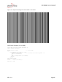
1
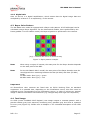
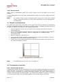
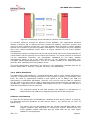
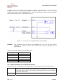
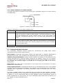
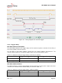
MV-D640 User’s Manual
4.6.3 Strobe Output
When using a CameraLink model, the strobe output must be provided by the frame
grabber.
For the USB models, there is an opto isolated strobe output on the power supply connector
available.
Note:
The strobe output needs a separate power supply due to the opto-coupled
output. Please see Section 5.1.4 for more information. For the configuration,
see [MAN025].
4.7 Black Level Adjustment
The black level offset (the mean value of the image when the lens aperture is completely
closed) is calibrated by factory for Gain=2 (default setting). Changing the gain may need
to adjust the black level offset with the following procedure:
1. Close the aperture of the lens, or close the lens opening of the camera with the
camera body cap.
2. In your frame grabber software, display a histogram of the captured black image. If
there is no histogram available, store the image and use a standard image
manipulation tool.
3. Open the camera in PFRemote 1.0.
4. In the 'Special' tab of PFRemote, change the value of 'Black Level Offset', until the
histogram of the black image looks as in Figure 7.
5. To save the current settings including the new black level offset in the camera, use
the "Store as defaults" button.
Figure 7: Histogram for a correct black level
Note:
For PFRemote version 0.65, refer to Chapter 12.
4.8 Configuration Interface
4.8.1 CameraLink Interface
A CameraLink camera can be controlled by the user via an RS232 compatible asynchronous
serial interface. This interface is contained within the CameraLink interface as shown in
Figure 8 and is physically not directly accessible. Instead, the serial communication is
usually routed through the frame grabber. For some frame grabbers it might be necessary
to connect a serial cable from the frame grabber to the serial interface of the PC.
REV: 2.0
Page 20