1
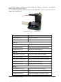
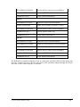
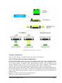
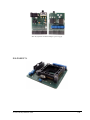
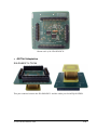
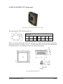
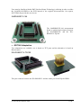
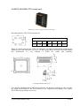
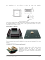
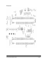
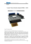
_ V2.2 Hardware Reference Renesas RH850/F1L Emulation Adapter RH850 Emulation Adapter System The RH850/F1L emulation adapter primary use case is providing the trace functionality (OnChip Trace Buffer, Software Trace, User Trace Port) for smaller RH850/F1L series packages (pincounts), where typically on-chip trace logic is not available. The emulation adapter is based on the 176-pin superset device and provides the adaptation to 48-pin, 64-pin, 80-pin and 100-pin QFP package. Second use case is a standalone operation. In this case customer can start developing and testing the application while his target may not be available yet. Renesas RH850/F1L emulation adapter is based on Renesas RH850/F1L R7F7010352 device in the QFP176 package. This is a superset device with 2MB program flash and can emulate all RH850/F1L devices. Complete emulation system is split into individual parts which makes the system flexible. A typical setup in conjunction with the target contains: IEA-RH850F1L (MCU part) Pin count conversion board either for TET or Renesas adaptation TET or Renesas solder part Optional measurement boards are available for each pin count and expose all microcontroller pins for measurement and inspection. Also optional is a power supply part, which can be used iSYSTEM, October 2014 1/24 for emulation adapter standalone operation (without the target) or when there are problems with the target supplying the power. For a standalone operation without the target the IEA-RH850F1L (MCU) and IEA-PS (Power Supply) are required only. Standalone operation – minimum setup Ordering Code: Description: IEA-RH850F1L Emulation Adapter IEA-PS Emulation Adapter Power Supply QFP144 IEA-RH850F1L-TQ144 TQ144 Pin Count Conversion Board IA144TQ-SOLDER Solder Part TQ144QFP (20 mm x20 mm) IAMRH850F1L144 144-pin Measurement Board QFP100 IEA-RH850F1L-TQ100 TQ100 Pin Count Conversion Board IA100TQ-SOLDER Solder Part TQ100QFP (14 mm x14 mm) IEA-RH850F1L-REN100 Renesas 100-Pin Count Conversion Board IAQB100GCTC01S Renesas QFP100 Solder Part IAMRH850F1L100 100-pin Measurement Board QFP80 IEA-RH850F1L-TQ80 TQ80 Pin Count Conversion Board IEA-RH850F1L-ATQ80W TQ80 Pin Count Conversion Flexible Board IA80ATQ-SOLDER Solder Part TQ80QFP (12 mm x 12 mm) iSYSTEM, October 2014 2/24 IEA-RH850F1L-REN80 Renesas 80-Pin Count Conversion Board IAQB80GKTC01S Renesas QFP80 Solder Part IAMRH850F1L80 80-pin Measurement Board QFP64 IEA-RH850F1L-TQ64 TQ64 Pin Count Conversion Board IA64ATQ-SOLDER Solder Part TQ64QFP (10 mm x 10 mm) IEA-RH850F1L-REN64 Renesas 64-Pin Count Conversion Board IAQB64GBTC01S Renesas QFP64 Solder Part IAMRH850F1L64 64-pin Measurement Board QFP48 IEA-RH850F1L-TQ48 TQ48 Pin Count Conversion Board IEA-RH850F1L-TQ48W TQ48 Pin Count Flexible Conversion Board IA48TQ-SOLDER Solder Part TQ48QFP (7 mm x 7 mm) IEA-RH850F1L-REN48 Renesas 48-Pin Count Conversion Board IAQB48GATC01S Renesas QFP48 Solder Part IAMRH850F1L48 48-pin Measurement Board The RH850/F1L emulation adapter is used in conjunction with iSYSTEM iC5000 debug and test tool. iC5000 connects to the ST1 connector on the emulation adapter through the 40-pin flat cable, which comes along the iC5000 unit. iSYSTEM, October 2014 3/24 RH850/F1L emulation adapter “ecosystem” Jumper configuration Note: On the PCB, pin 1 is marked with a white square around the pin. J0-J5: CPU port JP0 connection configuration Port JP0 signals JP0.0 to JP0.5 can operate in alternate modes. They can be configured either for one of the available debug interfaces or for standard I/O operation. When comparing to the JTAG debug interface (6 signals), LPD1 debug interface requires only one JP0 line and leaving remaining lines for the user respectively target usage. Similarly, LPD4 debug interface requires four JP0 line and leaving remaining line for the user (target) usage. Jumpers J0-J5 defines where JP0.0-JP0.5 signals connect, either to the debug connection on the emulation adapter or to the target. The JP0 port configuration is set through Option bytes (refer to the microcontroller reference manual for more details) and can be configured in 4 different ways. Position 1-2: JP0.x connected to the debug connector Position 2-3: JP0.x connected to the target iSYSTEM, October 2014 4/24 The following table reflects possible variations: Port Signal Jumper JTAG LPD4* LPD1 I/O (no debug) JP0.0 TDI J0 1-2 1-2 1-2 2-3 JP0.1 TDO J1 1-2 1-2 2-3 2-3 JP0.2 TCK J2 1-2 1-2 2-3 2-3 JP0.3 TMS J3 1-2 2-3 2-3 2-3 JP0.4 TRST J4 1-2 2-3 2-3 2-3 JP0.5 RDY J5 1-2 1-2 2-3 2-3 * default setting J6: User Trace configuration Jumper J6 is per default set in position 1-2 (manufacturing position) and must not be changed by the user. Position 2-3 is reserved for future debug extensions. Jumper User Trace Port Reserved J6 1-2 2-3 J7: target reset configuration Jumper J7 connects the reset line between the emulation device and the target. By default J7 is populated. In case when the debugger has problems connecting to the microcontroller or when the debugging is unpredictable, it is recommended removing the jumper for troubleshooting purpose since the target reset can be one of possible reasons preventing the debugger gaining full control over the microcontroller. iSYSTEM, October 2014 5/24 P2: power selection The P2 header row is used for power supply selection. Power supplies are organized in groups and the same voltage must be supplied for each group: POWER_1 = REG0VDD, REG1VDD, I0VDD, OSCVDD, E0VDD, E1VDD POWER_3 = REG2VDD POWER_5 = A0VDD GND = all VSS Refer to the microcontroller user manual for more details which power supply designation belongs to which power supply. Signal Signal Pin Pin Signal Signal direction direction target TPOWER_1 1 2 POWER_1 CPU target TPOWER_1 3 4 POWER_1 CPU target TPOWER_3 5 6 POWER_3 CPU target TPOWER_3 7 8 POWER_3 CPU target TPOWER_5 9 10 POWER_5 CPU target TPOWER_5 11 12 POWER_5 CPU NC 13 14 NC NC 15 16 NC NC 17 18 NC NC 19 20 NC GND 21 22 GND GND 23 24 GND GND 25 26 GND P4 signal description By default jumpers are set and connect target power supply coming from the target to the microcontroller residing on the emulation adapter. If a different power source is to be used (e.g. in case of standalone operation), jumpers must be removed, and power source must be applied to POWER_1 ( pins 2,4 ), POWER_3 ( pins 6,8 ), POWER_5 ( pins 10,12 ), and GND ( pins 22,24,26 ) signals. iSYSTEM power supply adapter can be ordered separately under the IEA-PS ordering code. It connects on top of the emulation adapter directly to the U3 header row and allows standalone usage of the emulation adapter. 3.3V or 5V voltage can be selected for each group with appropriate jumpers J0-J9. This is convenient when the target is not available or it’s not adjusted for the emulation adapter connection yet. iSYSTEM, October 2014 6/24 IEA-PS (optional emulation adapter power supply IEA-RH850F1L iSYSTEM, October 2014 7/24 Next picture shows a pinout of the four connectors on the bottom side of the IEA-RH850F1L. NC 142 144 146 148 150 152 154 156 158 160 162 164 166 168 170 172 174 176 NC NC 141 143 145 147 149 151 153 155 157 159 161 163 165 167 169 171 173 175 NC NC NC 140 138 136 134 132 130 128 126 124 122 120 118 116 114 112 110 108 106 104 102 100 98 96 94 92 90 NC NC NC NC 139 137 135 133 131 129 127 125 123 121 119 117 115 113 111 109 107 105 103 101 99 97 95 93 91 89 NC NC NC 87 85 83 NC 88 86 84 81 82 79 80 77 78 75 76 73 74 71 72 69 70 67 68 65 66 63 64 61 62 59 60 57 58 55 56 53 54 NC NC 1 3 5 7 9 11 13 15 17 19 21 23 25 27 29 31 33 35 37 39 41 43 45 47 49 51 NC NC NC NC NC – Not Connected A user target could also be designed for connecting the IEA-RH850F1L directly to the target board. Connectors being used on the IEA-RH850F1L are female Tyco Electronics connectors, part number 0-0104652-4 (40 pin) and 0-0104652-6 (60 pin). iSYSTEM, October 2014 8/24 NC NC 2 4 6 8 10 12 14 16 18 20 22 24 26 28 30 32 34 36 38 40 42 44 46 48 50 52 NC NC Bottom side of the IEA-RH850F1L QFP144 Adaptation IEA-RH850F1L-TQ144 This part connects between the IEA-RH850F1L and the solder part IA144TQ-SOLDER. iSYSTEM, October 2014 9/24 IA144TQ-SOLDER (TET solder part) Solder part, which is soldered down to the target. Recommended (by TET) PCB footprint size: (Unit: mm) A B C D E K L 22 1.125 23.0 23.0 2.15 25.05 25.05 When it’s meant soldering the solder part manually, it’s highly recommended prolonging the dimension E on the outer side (e.g. for 1.5-2 mm) during the PCB design. Note that without this modification it’s very difficult to solder the solder part manually. IA144TQ-SOLDER dimensions iSYSTEM, October 2014 10/24 User must be familiar with the SMT (Surface Mount Technology) soldering in order to solder the IA144TQ-SOLDER to the PCB instead of the original microcontroller. On request, iSYSTEM can provide this service too. IAMRH850F1L144 The IAMRH850F1L144 measurement board is optional and connects between the IEA-RH850F1L and the IEARH850F1L-TQ144. QFP100 Adaptation Two adaptations are available, one is based on TET parts and the alternative is based on Renesas parts. IEA-RH850F1L-TQ100 This part connects between the IEA-RH850F1L and the solder part IA100TQ-SOLDER. iSYSTEM, October 2014 11/24 IA100TQ-SOLDER (TET solder part) Solder part, which is being soldered to the target. Recommended (by TET) PCB footprint size: (Unit: mm) A B C D E K L 16.5 1.125 17.0 17.0 2.15 19.55 19.55 When it’s meant soldering the solder part manually, it’s highly recommended prolonging the dimension E on the outer side (e.g. for 1.5-2 mm) during the PCB design. Note that without this modification it’s very difficult to solder the solder part manually. IA100TQ-SOLDER dimensions User must be familiar with the SMT (Surface Mount Technology) soldering in order to solder the IA100TQ-SOLDER to the PCB instead of the original microcontroller. On request, iSYSTEM can provide this service too. iSYSTEM, October 2014 12/24 IEA-RH850F1L-REN100 This part connects between the IEA-RH850F1L and the solder part IAQB100GCTC01S from Renesas. IAQB100GCTC01S (Renesas solder part) User must be familiar with the SMT (Surface Mount Technology) soldering in order to solder the IAQB100GCTC01S to the PCB instead of the original microcontroller. On request, iSYSTEM can provide this service too. IAMRH850F1L100 The IAMRH850F1L100 measurement board is optional and connects between the IEARH850F1L and the IEA-RH850F1L-REN100 for Renesas adaptation and between the IEARH850F1L and the IEA-RH850F1L-TQ100 for TET adaptation. iSYSTEM, October 2014 13/24 QFP80 Adaptation Three adaptations are available, two are based on TET parts and the alternative is based on Renesas parts. IEA-RH850F1L-TQ80 This part connects between the IEA-RH850F1L and the solder part IA80ATQ-SOLDER. IEA-RH850F1L-ATQ80W This part connects between the IEA-RH850F1L and the solder part IA80ATQ-SOLDER. iSYSTEM, October 2014 14/24 IA80ATQ-SOLDER (TET solder part) Solder part, which is being soldered to the target Recommended (by TET) PCB footprint size: (Unit: mm) A B C D E K L 14.0 1.505 15.0 15.0 2.3 16.0 16.0 When it’s meant soldering the solder part manually, it’s highly recommended prolonging the dimension E on the outer side (e.g. for 1.5-2 mm) during the PCB design. Note that without this modification it’s very difficult to solder the solder part manually. IA80ATQ-SOLDER dimensions User must be familiar with the SMT (Surface Mount Technology) soldering in order to solder the IA80ATQ-SOLDER to the PCB instead of the original microcontroller. On request, iSYSTEM can provide this service too. iSYSTEM, October 2014 15/24 IEA-RH850F1L-REN80 This part connects between the IEA-RH850F1L and the solder part IAQB80GKTC01S from Renesas. IAQB80GKTC01S (Renesas solder part) User must be familiar with the SMT (Surface Mount Technology) soldering in order to solder the IAQB80GKTC01S to the PCB instead of the original microcontroller. On request, iSYSTEM can provide this service too. IAMRH850F1L80 The IAMRH850F1L80 measurement board is optional and connects between the IEARH850F1L and the IEA-RH850F1L-REN80 for Renesas adaptation and between the IEARH850F1L and the IEA-RH850F1L-TQ80 for TET adaptation. iSYSTEM, October 2014 16/24 QFP64 Adaptation Two adaptations are available, one is based on TET parts and the alternative is based on Renesas parts. IEA-RH850F1L-TQ64 This part connects between the IEA-RH850F1L and the solder part IA64ATQ-SOLDER. IA64ATQ-SOLDER (TET solder part) Solder part, which is being soldered to the target. Recommended (by TET) PCB footprint size: (Unit: mm) A B C D E K L 12 1.505 13.0 13.0 2.3 14 14 When it’s meant soldering the solder part manually, it’s highly recommended prolonging the dimension E on the outer side (e.g. for 1.5-2 mm) during the PCB design. Note that without this modification it’s very difficult to solder the solder part manually. iSYSTEM, October 2014 17/24 IA64ATQ-SOLDER dimensions User must be familiar with the SMT (Surface Mount Technology) soldering in order to solder the IA64ATQ-SOLDER to the PCB instead of the original microcontroller. On request, iSYSTEM can provide this service too. IEA-RH850F1L-REN64 This part connects between the IEA-RH850F1L and the solder part IAQB64GBTC01S from Renesas. IAQB64GBTC01S (Renesas solder part) User must be familiar with the SMT (Surface Mount Technology) soldering in order to solder the IAQB64GBTC01S to the PCB instead of the original iSYSTEM, October 2014 18/24 microcontroller. On request, iSYSTEM can provide this service too. IAMRH850F1L64 The IAMRH850F1L64 measurement board is optional and connects between the IEARH850F1L and the IEA-RH850F1L-REN64 for Renesas adaptation and between the IEA-RH850F1L and the IEA-RH850F1LTQ64 for TET adaptation. QFP48 Adaptation Three adaptations are available, two are based on TET parts and the alternative is based on Renesas parts. IEA-RH850F1L-TQ48 This part connects between the IEA-RH850F1L and the solder part IA48TQ-SOLDER. iSYSTEM, October 2014 19/24 IEA-RH850F1L-TQ48W This part connects between the IEA-RH850F1L and the solder part IA48TQ-SOLDER. IA48TQ-SOLDER (TET solder part) Solder part, which is being soldered to the target. Recommended (by TET) PCB footprint size (in mm): (Unit: mm) A B K L 9.0 1.005 12.0 12.0 When it’s meant soldering the solder part manually, it’s highly recommended prolonging the dimension E on the outer side (e.g. for 1.5-2 mm) during the PCB design. Note that without iSYSTEM, October 2014 20/24 this modification it’s very difficult to solder the solder part manually. IA48TQ-SOLDER dimensions User must be familiar with the SMT (Surface Mount Technology) soldering in order to solder the IA48TQ-SOLDER to the PCB instead of the original microcontroller. On request, iSYSTEM can provide this service too. IEA-RH850F1L-REN48 This part connects between the IEA-RH850F1L and the solder part IAQB48GATC01S from Renesas. IAQB48GATC01S (Renesas solder part) User must be familiar with the SMT (Surface Mount Technology) soldering in order to solder the IAQB48GATC01S to the PCB instead of the original microcontroller. On request, iSYSTEM can provide this service too. iSYSTEM, October 2014 21/24 IAMRH850F1L48 The IAMRH850F1L48 measurement board is optional and connects between the IEARH850F1L and the IEA-RH850F1L-REN48 for Renesas adaptation and between the IEARH850F1L and the IEA-RH850F1LTQ48(W) for TET adaptation. iSYSTEM, October 2014 22/24 Schematic iSYSTEM, October 2014 23/24 Disclaimer: iSYSTEM assumes no responsibility for any errors which may appear in this document, reserves the right to change devices or specifications detailed herein at any time without notice, and does not make any commitment to update the information herein. iSYSTEM. All rights reserved. iSYSTEM, October 2014 24/24