1
DIGITAL Laser Printer LN15
SERVICE MANUAL
&
PARTS CATALOG
EK-LN15X-SV.A01
CONTENTS
CHAPTER 1
GENERAL DESCRIPTION .................................................................................................. 1-1
1.1
INTRODUCTION ...................................................................................................................................... 1-1
1.2
EQUIPMENT CONSTRUCTION ............................................................................................................. 1-2
1.2.1
General ................................................................................................................................................. 1-2
1.2.2
Model Configuration ........................................................................................................................... 1-2
1.2.3
Structure ............................................................................................................................................... 1-4
(1)
Covers ........................................................................................................................................ 1-6
(2)
Laser unit.................................................................................................................................... 1-7
(3)
Printer mechanism...................................................................................................................... 1-8
(4)
Print unit (user replaceable) ....................................................................................................... 1-9
(5)
Cleaner assembly ....................................................................................................................... 1-9
(6)
Power supply unit..................................................................................................................... 1-10
(7)
Shield plate ............................................................................................................................... 1-11
(8)
Control board ........................................................................................................................... 1-11
(9)
Sensor board assembly ............................................................................................................. 1-12
(10) Paper tray ................................................................................................................................. 1-12
(11) Multi-function feeder ............................................................................................................... 1-12
CHAPTER 2
INSTALLATION .................................................................................................................... 2-1
2.1
GENERAL DESCRIPTION ....................................................................................................................... 2-1
2.2
INSTALLATION PRECAUTIONS ........................................................................................................... 2-1
2.3
UNPACKING ............................................................................................................................................. 2-2
2.4
INSPECTION AFTER UNPACKING ....................................................................................................... 2-3
CHAPTER 3
TROUBLESHOOTING ......................................................................................................... 3-1
3.1
WHEN THE POWER INDICATOR DOES NOT LIGHT ........................................................................ 3-3
3.2
WHEN PRINTING QUALITY IS ABNORMAL ...................................................................................... 3-4
(1)
When faint .................................................................................................................................. 3-5
(2)
When deep.................................................................................................................................. 3-6
(3)
Black vertical line ...................................................................................................................... 3-7
(4)
White vertical line ...................................................................................................................... 3-8
(5)
Lacking space at the top and bottom .......................................................................................... 3-9
(6)
Black point, white point ........................................................................................................... 3-10
(7)
Second printing (ghost printing) .............................................................................................. 3-11
(8)
Dirty back/edge ........................................................................................................................ 3-12
i
(9)
Black ........................................................................................................................................ 3-13
(10) White ........................................................................................................................................ 3-14
(11) Blur........................................................................................................................................... 3-15
(12) Smudge..................................................................................................................................... 3-16
3.3
ERROR AND STATUS MESSAGES ..................................................................................................... 3-17
3.3.1
Error Messages .................................................................................................................................. 3-17
3.3.2
Status Messages ................................................................................................................................. 3-18
3.4
RESETTING THE PRINT UNIT (FUSER UNIT) COUNTER .............................................................. 3-20
3.5
OTHERS ................................................................................................................................................... 3-22
CHAPTER 4
MAINTENANCE .................................................................................................................... 4-1
4.1
GENERAL .................................................................................................................................................. 4-1
4.2
GENERAL PRECAUTIONS ..................................................................................................................... 4-1
4.3
MAINTENANCE TOOLS ......................................................................................................................... 4-2
4.4
MAINTENANCE LEVELS ....................................................................................................................... 4-3
4.5
PREVENTIVE MAINTENANCE ............................................................................................................. 4-3
4.6
PARTS DRAWINGS ................................................................................................................................. 4-4
4.7
PARTS THAT MUST NOT BE DISASSEMBLED .................................................................................. 4-6
4.8
LEVEL 1 MAINTENANCE ...................................................................................................................... 4-7
4.8.1
Cleaning ............................................................................................................................................... 4-7
4.8.2
Consumables Replacement .................................................................................................................. 4-9
4.9
LEVEL 2 MAINTENANCE .................................................................................................................... 4-11
4.9.1
Replacement ...................................................................................................................................... 4-11
(1)
Upper cover replacement ......................................................................................................... 4-12
(2)
Control panel replacement ....................................................................................................... 4-15
(3)
Laser unit replacement ............................................................................................................. 4-18
(4)
Fuser unit replacement ............................................................................................................. 4-19
(5)
Power supply board replacement ............................................................................................. 4-21
(6)
FAN 1 replacement .................................................................................................................. 4-22
(7)
FAN 2 replacement .................................................................................................................. 4-23
(8)
Control board replacement ....................................................................................................... 4-24
(9)
High-voltage power supply board and sensor board replacement ........................................... 4-25
(10) Main motor replacement .......................................................................................................... 4-27
(11) Pick-up motor replacement ...................................................................................................... 4-28
(12) Pick-up roller replacement ....................................................................................................... 4-29
(13) Resist motor replacement ......................................................................................................... 4-31
(14) Paper feed roller replacement .................................................................................................. 4-32
(15) Transfer charger unit replacement ........................................................................................... 4-35
i i
(16) Cover-open switch replacement ............................................................................................... 4-36
(17) Volume board replacement ...................................................................................................... 4-37
(18) Stacker-full sensor board (SFS board) replacement ................................................................ 4-38
(19) Frame-2 assembly replacement ................................................................................................ 4-39
(20) Multi-function feeder board (MFF board) replacement ........................................................... 4-40
(21) Separator assembly (friction pad holder) replacement............................................................. 4-41
(22) Print unit disassembly .............................................................................................................. 4-42
4.9.2
Lubrication and Precautions .............................................................................................................. 4-43
(1)
Base frame assembly ................................................................................................................ 4-44
(2)
Frame L assembly .................................................................................................................... 4-45
(3)
Fuser unit.................................................................................................................................. 4-46
(4)
Main motor unit ....................................................................................................................... 4-47
(5)
Frame-2 assembly .................................................................................................................... 4-48
(6)
Guide assembly ........................................................................................................................ 4-49
(7)
Feed-2 assembly ....................................................................................................................... 4-50
(8)
Gear box assembly ................................................................................................................... 4-51
(9)
Gear box lever assembly .......................................................................................................... 4-52
(10) Developing unit ........................................................................................................................ 4-53
(11) Magnet roller bracket assembly ............................................................................................... 4-55
(12) Heat roller subunit .................................................................................................................... 4-56
(13) Heat roller base unit ................................................................................................................. 4-57
4.10 DIAGNOSTICS ........................................................................................................................................ 4-58
4.10.1 Printing the Status Report .................................................................................................................. 4-58
4.10.2 MarkVision, Printer Management Utility Program by Lexmark....................................................... 4-61
(1)
Installing MarkVision .............................................................................................................. 4-61
(2)
Menu bar functions .................................................................................................................. 4-62
4.10.3 PPMENU Program ............................................................................................................................ 4-63
(1)
Installing PPMENU ................................................................................................................. 4-63
(2)
Menu functions and items ........................................................................................................ 4-64
4.10.4 Special Functions for Maintenance ................................................................................................... 4-67
(1)
Maintenance modes.................................................................................................................. 4-67
(2)
How to execute a maintenance mode ....................................................................................... 4-68
(3)
Information printed in test print mode ..................................................................................... 4-69
(4)
EEPROM CLEAR and EEPROM CLEAR Extension ............................................................ 4-70
(5)
Re-entry of the serial number of printer ................................................................................... 4-70
iii
CHAPTER 5
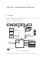
DESCRIPTION OF OPERATION ....................................................................................... 5-1
5.1
GENERAL .................................................................................................................................................. 5-1
5.2
MECHANICAL OPERATION .................................................................................................................. 5-2
5.3
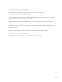
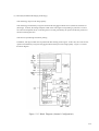
ELECTRICAL OPERATION .................................................................................................................... 5-6
5.3.1
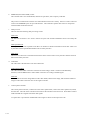
System Diagram................................................................................................................................... 5-6
5.3.2
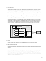
Main Controller ................................................................................................................................... 5-8
5.3.3
5.3.4
5.3.5
(1)
CPU .......................................................................................................................................... 5-10
(2)
RAM......................................................................................................................................... 5-10
(3)
ROM......................................................................................................................................... 5-10
(4)
Expansion interface .................................................................................................................. 5-11
(5)
LSI-1 ........................................................................................................................................ 5-11
(6)
Print density converter LSI ...................................................................................................... 5-13
(7)
Reset circuit.............................................................................................................................. 5-13
Engine Controller Block Diagram ..................................................................................................... 5-15
(1)
CPU .......................................................................................................................................... 5-17
(2)
ROM......................................................................................................................................... 5-18
(3)
LSI ............................................................................................................................................ 5-18
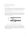
Interface Communication Method ..................................................................................................... 5-19
(1)
Centronics parallel interface .................................................................................................... 5-19
(2)
RS-232C interface (option) ...................................................................................................... 5-20
(3)
FEIT (Fujitsu Enhanced Imaging Technology) ....................................................................... 5-21
Printing Method ................................................................................................................................. 5-22
(1)
Print control process................................................................................................................. 5-22
(2)
Bit-map data generate .............................................................................................................. 5-22
(3)
Video data transfer ................................................................................................................... 5-23
(4)
LD unit ..................................................................................................................................... 5-23
(5)
Heat roller temperature control ................................................................................................ 5-23
(6)
Power saving control ................................................................................................................ 5-24
(7)
Alarm detect ............................................................................................................................. 5-24
5.3.6
Control Panel Control ........................................................................................................................ 5-25
5.3.7
Power Supply ..................................................................................................................................... 5-26
(1)
Overcurrent protection ............................................................................................................. 5-26
(2)
Overvoltage protection ............................................................................................................. 5-26
(3)
PW STOP signal ...................................................................................................................... 5-26
CHAPTER 6
i v
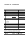
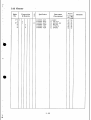
REPLACEMENT PARTS ..................................................................................................... 6-1
ILLUSTRATIONS AND TABLES
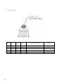
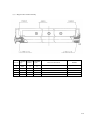
Figure 1-1 Digital Laser Printer LN15 ............................................................................................................... 1-3
Figure 1-2 Structure ............................................................................................................................................ 1-5
Figure 1-3 Laser Unit .......................................................................................................................................... 1-7
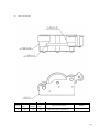
Figure 1-4 Printer Mechanism ............................................................................................................................ 1-8
Figure 1-5 Power Supply Unit .......................................................................................................................... 1-10
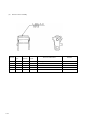
Figure 1-6 Control Board .................................................................................................................................. 1-11
Figure 2-1 Shipping Carton and Printer and its Accessories ............................................................................. 2-2
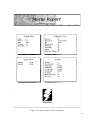
Figure 2-2 Status Report (FPS Emulation) ......................................................................................................... 2-6
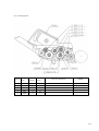
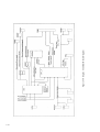
Figure 3-1 Printer Elements and Connections .................................................................................................... 3-2
Figure 3-2 Abnormal Print Quality .................................................................................................................... 3-4
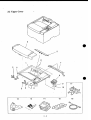
Figure 4-1 Basic Components ............................................................................................................................. 4-4
Figure 4-1 Basic Components - Continued ........................................................................................................ 4-5
Figure 4-2 Cleaning the Paper Path .................................................................................................................... 4-8
Figure 4-3 Cleaning the Corona Wire ................................................................................................................ 4-8
Figure 4-4 Cleaning the Precharger Wire ........................................................................................................... 4-9
Figure 4-5 Status Report (FPS Emulation) ....................................................................................................... 4-59
Figure 4-6 Front Report (FPS Emulation) ........................................................................................................ 4-60
Figure 4-7 MarkVision Main Screen (Initial Status) ....................................................................................... 4-62
Figure 4-8 MarkVision Status Screen (Cover Open) ....................................................................................... 4-63
Figure 4-9 PPMENU Main Menu (Concept) .................................................................................................... 4-64
Figure 4-10 Maintenance Mode Operation Flowchart ..................................................................................... 4-71
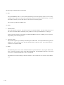
Figure 5-1 Printer Block Diagram ...................................................................................................................... 5-1
Figure 5-2 Picking, Printing, Fusing, and Ejecting Paper .................................................................................. 5-2
Figure 5-3 Structure of the Paper Feed Drive Unit ............................................................................................ 5-3
Figure 5-4 Process Drive Unit ............................................................................................................................ 5-4
Figure 5-5 Print Unit ........................................................................................................................................... 5-5
Figure 5-6 System Diagram ................................................................................................................................ 5-6
Figure 5-7 Connection Diagram ......................................................................................................................... 5-7
Figure 5-8 Main Controller Block Diagram ....................................................................................................... 5-9
Figure 5-9 Control Board Block Diagram ........................................................................................................ 5-14
Figure 5-10 Engine Controller Block Diagram ................................................................................................ 5-16
Figure 5-11 Centronics Parallel Interface Signal Timing Chart ...................................................................... 5-19
Figure 5-12 RS-232C Serial Interface Signal Timing Chart ............................................................................ 5-20
Figure 5-13 Block Diagram (Internal Configuration) ...................................................................................... 5-21
Figure 5-14 Print Process Block Diagram ........................................................................................................ 5-22
Figure 5-15 Video Data Transfer Block Diagram ............................................................................................ 5-23
Figure 5-16 Control Panel Block Diagram ....................................................................................................... 5-25
Figure 5-17 Power Supply Block Diagram ....................................................................................................... 5-27
v
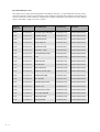
Table 3-1 Error Messages .................................................................................................................................. 3-17
Table 3-2 Action-required Status Messages ...................................................................................................... 3-18
Table 3-3 Printer Status Messages .................................................................................................................... 3-19
Table 4-1 Maintenance Tools .............................................................................................................................. 4-2
Table 4-2 Parts That Must Not be Disassembled ................................................................................................ 4-6
Table 4-3 Cleaning .............................................................................................................................................. 4-7
Table 4-4 PPMENU Factory Defaults When Emulation is PCL ...................................................................... 4-66
Table 4-5 Special Maintenance Modes ............................................................................................................. 4-67
v i
PREFACE
This manual is for maintenance engineers and discusses the operation, installation, and maintenance of the
DIGITAL Laser Printer LN15. The topics covered are:
Chapter 1: Printer specifications, performance, and configuration
Chapter 2: Installation precautions and unpacking
Chapter 3: Diagnosing mechanical and electronic problems
Chapter 4: Maintenance procedures (cleaning, lubrication, inspection, adjustment), procedures for replacing
parts, and list of tools
Chapter 5: Principles of operation (mechanical and electrical operations)
Chapter 6: Replacement parts
CHAPTER 1
GENERAL DESCRIPTION
1.1 INTRODUCTION
This manual is for maintenance service engineers. The DIGITAL Laser printer LN15 is based on the QMS
Desklaser 1400P printer that is manufactured by Fujitsu using the PrintPartner 14ADV printer engine. This
manual is customized for the DIGITAL Laser Printer LN15 from the PrintPartner 14ADV Service Manual &
Part Catalog. It covers maintenance and detailed information such as trouble-shooting and component replacement. Information unique to the DIGITAL Laser printer LN15 are documented.
DIGITAL Laser Printer LN15 Service Manual and Parts Catalog (EK-LN15X-SV)
There are two companion manuals for PrintPartner 14ADV maintenance service engineers:
PrintPartner 14ADV Page Printer Parts Catalogue (Order No. C145-G019)
PrintPartner 14ADV Page Printer Schematic Diagrams (Order No. C145-F038)
For the optional duplex unit, the following manual is available.
Duplex Unit Parts Catalogue (Order No. C145-G020)
Most information is covered in this manual. The other two manuals are mostly for reference. These three
manuals contain all the information necessary for LN15 laser printer maintenance.
The LN15 laser printer is a reliable machine with a simple mechanism that requires little maintenance.
1-1
1.2 EQUIPMENT CONSTRUCTION
1.2.1 General
This section outlines the construction and features of the LN15 laser printer .
1.2.2
Model Configuration
Model and input voltage
Printer
LN15P-AC : 220–240 VAC (for Europe), 11MB, No Network card +
central Europe power cord
LN15N-AC : 220–240 VAC (for Europe), 19MB, Ethernet Card
10-BASE-2 (BNC) + Central Europe power cord
LN15N-AB : 220–240 VAC (for Europe), 19MB, Ethernet Card
10-BASE-T (Twisted pair) + Central Europe power cord
Options
LN15X-TA Paper trays (tray 1; 550 sheets): A4, Letter, and Legal sizes
LN15X-TB Paper trays (tray 2; 500 sheets): A4, A5, Letter, Legal, and
Executive sizes
LN15X-TC Paper feeder (feeder unit + paper tray 2): A4 or Letter size
LN15X-DA Duplex unit (two-sided printing mechanism)
LN15X-SI Serial interface board RS-232C/422A (For LN15P)
LN15X-AT LocalTalk board: AppleTalk compatible (For LN15P)
LN15X-NA Ethernet board 10-BASE-2 (for LN15P)
LN15X-NB Ethernet board 10-BASE-T (for LN15P)
LNXXM-AE 8MB Memory expansion
LNXXM-AF 16MB Memory expansion
LNXXM-AG 32MB Memory expansion
LN15X-MF Multifunction Feeder paper tray
The entry model LN15P printer has 11 MegaBytes of RAM, HP LaserJet 4 (PCL5e) and PostScript level 2
emulations, and a Centronics parallel interface (bi-directional). Its paper tray size is A4 for Europe, Asia, and
Australia. The network printer models LN15N-AC and LN15N-BC have 19 MegaBytes HP LaserJet 4 (PCL5e)
and PostScript level 2 emulations, and a Ethernet card.
1-2
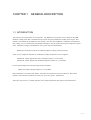
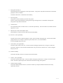
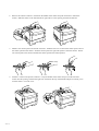
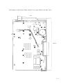
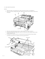
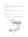
Shade cover
(cleaner assembly inside)
Stacker-full sensor
Top cover
(Paper stacker)
Control panel
Upper door
Paper guides
for manual feeding
Multi-function feeder
(MFF)
Slide cover
(Font/emulation card slot
and RAM card slots inside)
Front cover
(opened)
Paper guides
for stack feeding
Multi-function feeder
cable
Paper tray
[ Front and right side view]
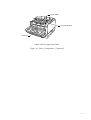
Rear stacker
Interface board
slot cover
Power switch
Centronics parallel
interface connector
Power cord
connector
[ Rear and left side view ]
Figure 1-1 LN15 Laser Page Printer
1-3
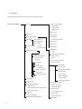
1.2.3 Structure
The standard printer without options has the following structure.
LN15 Laser printer
Upper cover assembly
Covers
Ozone filter
Control panel
Shade cover
Side cover L
Laser unit
Side cover R
Printer mechanism
Front frame
Print unit
OPC drum unit
Developing unit
Toner bottle
Cleaner assembly
Cleaner
Cleaner holder
Power supply unit
Toner empty sensor
Front cover
Back cover
Rear stacker
Metal frame
Fan 1
Process drive mechanism
Main power supply
Power switch
AC inlet
Fuser unit
Main motor
Gears
Paper pick-up mechanism
Pick-up motor
Cover
Paper guide
assembly 1
Paper eject sensor
Paper guide
Guide open switch
Base frame
Paper sensor
Paper feed mechanism
Resist motor
Resist roller
Paper feed roller
Pick-up roller
Fan 2
Shield plate
Control board
Sensor board assembly
Sensor boards
High-voltage power supply board
Paper empty sensor
Paper tray
Friction pad holder
Multi-function feeder (MFF)
1-4
Transfer charger unit
Paper guide assembly 2
Paper eject roller
Stack full sensor
Print unit guide
Cover open switch
Volume board
Print density dial
MFF board
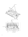
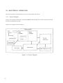
Printer + optional duplex unit + optional paper feeder
Print unit
Toner bottle
Laser unit
OPC drum
Heat roller
(fuser unit)
Cleaner assembly
Upper cover
assembly
Resist roller
Eject roller
Paper feed roller
Multi-Function
feeder (Option)
Pick-up roller
Paper tray 1
Duplex unit
(option)
Paper feeder
(feeder unit +
paper tray)
(option)
Paper tray 2
(option)
: Paper path
Transfer charger unit
Figure 1-2 Structure
1-5
(1) Covers
The covers consist of the following:
• Upper cover assembly
• Side cover L
• Side cover R
• Front frame
• Front cover
• Back cover
• Stacker
a.
Upper cover assembly
The upper cover assembly covers the top of the printer mechanism and stacks printed paper.
The upper cover assembly has a hinge to enable the front (upper door) to open. The print unit and toner
bottle can be replaced when the upper door is open.
The upper cover has a hinge to enable the shade cover to open. The cleaner can be replaced when the shade
cover is open.
The control panel is located at the top right and the ozone filter is inserted at the right rear. It consists of
four LED indicators, an LCD, and eight push-button switches, enabling communication between the user
and printer.
b.
Side cover L
This cover covers the left side of the printer mechanism.
c.
Side cover R
This cover covers the right side of the printer mechanism.
This cover is opened to add or replace optional cards (RAM card or emulation card).
d.
Front frame
This frame is secured to the front of the printer mechanism.
e.
Front cover
This cover is opened when paper is fed manually or the multi-function feeder is used.
f.
Back cover
This cover covers the rear of the printer mechanism.
g.
Rear stacker
The rear stacker can be opened or closed to select the output destination of printed paper. The rear stacker is
usually closed to eject paper to the upper cover side.
When envelopes, labels, or transparencies are used, the rear stacker must be opened to eject paper to the rear
and stack it.
Also when a paper jam occurs, the rear stacker is opened to remove the jammed paper.
1-6
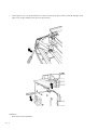
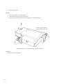
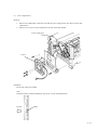
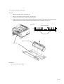
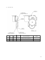
(2) Laser unit
The laser unit is provided in the upper cover.
Images are written on the photoconductive drum of the print unit by laser beams emitted from the laser unit.
Caution label
Figure 1-3 Laser Unit
! CAUTION
▲
: Do not look at a laser beam directly.
This label is put on the laser unit.
“
1-7
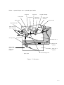
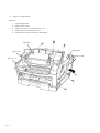
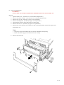
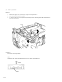
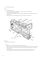
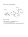
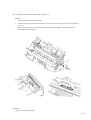
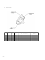
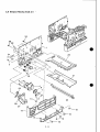
(3) Printer mechanism
Figure 1-4 Printer Mechanism
a.
Metal frame
This frame is the basic frame of the printer mechanism and made of sheet metals.
All parts are tightened with screws or snap-fitted to this frame.
The fan (FAN1) is installed on this frame.
b.
Process drive mechanism
This mechanism consists of the mechanism that drives the print unit and fuser unit, a DC motor, and drive
system (gears, etc.).
c.
Paper pick-up mechanism
This mechanism feeds paper loaded in the paper tray to the base frame of the printer mechanism sheet by
sheet.
This mechanism consists of a stepping motor and drive system (gears, etc.).
d.
Base frame
This frame is main part of the mechanism that transports paper and transfers toner to the paper.
• Sensor that detects the picked paper
• Transfer charger unit (service technicians replaceable)
• Paper feed mechanism
(A stepping motor, resist roller, paper feed roller, and pick-up roller are tightened with screws or snapfitted to this frame.)
1-8
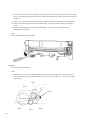
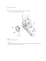
e.
Paper guide assembly 2
This guide transports printed paper to the output stacker. This guide is snap-fitted to the frame on which the
paper eject roller is installed.
The stacker-full sensor is installed on this assembly.
f.
Print unit guide
This guide is used to install the print unit in the printer.
The cover open switch that detects opening and closing of the upper door is installed on the left guide.
This guide is snap-fitted to the frame.
g.
Volume board
The volume board has a variable resistor to control the print density. The control dial is accessible when the
upper door is open.
h.
Multi-function feeder board (MFF board)
This board has a connector for the multi-function feeder (MFF).
(4) Print unit (user replaceable)
The print unit consists of a photoconductive (OPC) drum unit and a developing unit. It lasts about 30,000
pages printed at 5% coverage in continuous print mode at 25°C (77°F) and 50% RH.
It can be changed easily by the user.
a.
Toner bottle (user replaceable)
The toner bottle contains new toner. It lasts for about 5,000 pages printed at 5% coverage in continuous
print mode. However, the toner bottle installed on the new print unit has a shorter life. It can be changed
easily by the user.
(5) Cleaner assembly
The cleaner assembly consists of a cleaner and a cleaner holder..
a.
Cleaner (user replaceable)
The cleaner wipes the heat roller. It lasts for about 5,000 pages printed at 5% coverage in continuous print
mode. It must be replaced by the user when the toner bottle is empty and replaced.
b.
Cleaner holder (reusable)
The cleaner holder holds the cleaner. It locks the cleaner by a simple mechanism which can be easily
operated by the user.
1-9
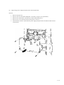
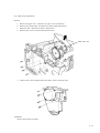
(6) Power supply unit
This unit consists of the following parts:
• Main power supply
- Power switch
- AC inlet
• Fuser unit
- Cover
- Paper guide assembly 1
- Paper eject sensor
- Paper guide
- Guide open switch
• Fan (FAN 2)
a.
Main power supply
The main power supply supplies +5 VDC and +24 VDC for the logic devices and printer mechanism.
There are two types of power supplies: one for input voltage of 120 VAC (not used on LN15) and the
other for 220 to 240 VAC.
The main power supply is equipped with a power switch and an AC inlet.
The main power supply is attached with screws to the cover of the fuser unit.
Figure 1-5 Power Supply Unit
b.
1-10
Fuser unit (service technicians replaceable)
The fuser unit has an aluminium heat roller and a pressure roller. It fixes the image of toner particles on the
paper using heat and pressure.
It has a temperature sensor and a thermal fuse for safety.
It lasts about for 100,000 pages printed at 5% coverage on A4 paper in continuous print mode. There are
two types: one for input voltage of 120 VAC (Not used on LN15) and the other for 220 to 240 VAC.
c.
Cover
This cover, classified as a component belonging under the fuser unit category, covers the main power
supply. It is attached on the bottom of the fuser unit and the power supply is installed under (inside) the
cover. The paper guide assembly 1 is also installed at the edge of the cover.
d.
Paper guide assembly 1
This assembly transports paper from the fuser unit to the eject roller.
When a paper jam occurs, the paper guide assembly can be drawn out to remove the jammed paper.
A guide open switch detects normal installation of the paper guide assembly.
e.
Fan (FAN 2)
This fan ventilates the power supply unit.
This fan is tightened with screws to the right side of the power supply unit.
(7) Shield plate
This plate covers the control board.
This plate is tightened with screws to the right side of the printer mechanism frame.
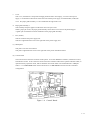
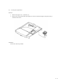
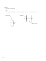
(8) Control board
The control board is the main controller of this printer. It has four ROMs for firmware, mechanism control,
and interface control. It has connectors for the Centronics interface cable and an optional interface board, an
optional memory expansion cards, and an emulation card of the future. The resident RAM is 3 MBytes.
There is 1 x 8 MB SIMMS board on the LN15P and 2 x 8 MB SIMMS board on LN15N as standard
configuration.
Figure 1-6 Control Board
1-11
(9) Sensor board assembly
a.
Sensor boards
There are two sensor boards.
They detect the presence of paper, the size of paper, paper empty, and paper ejection.
b.
High-voltage power supply board (HV board)
The high-voltage power supply, which supplies high voltage to the pre-charger and the transfer charger unit,
is tightened with screws to the left side of the sensor board assembly.
(10) Paper tray
The paper size is universal among A4, Letter, and Legal. The capacity of the paper tray (tray 1) is 550
sheets for 0.09 mm thick paper. An optional 500-sheet paper feeder (tray 2) is provided. Its paper size is
universal among A4, A5, Letter, Legal, and Executive.
(11)Multi-function feeder (Optional)
The multi-function feeder feeds envelopes, labels, transparencies, heavy paper, and nonstandard size paper.
The capacity is 100 sheets for 0.09 mm thick paper or 30 envelopes.
1-12
CHAPTER 2
INSTALLATION
2.1 GENERAL DESCRIPTION
The LN15 laser printer is well-packed for shipping, and can be unpacked easily.
After the printer is unpacked, it should be checked with a test printing prior to final installation. Installation
procedures are simple and require a minimum of time.
2.2
INSTALLATION PRECAUTIONS
Observe the following points when installing the printer:
• Install the printer on a level surface that does not have excessive vibration.
• Place the printer in a well-ventilated room, free of excessive dust.
• Do not place the printer in direct sunlight or near a heater.
• Do not expose the printer to high temperatures or high humidity. Temperature range is from 10°C to 35°C or
50°F to 95°F. Humidity range is between 20% (RH) and 80% (RH). The maximum wet-bulb temperature is
29°C or 84°F.
• Do not block the ventilation at the top and left sides of the printer.
• Use only the power cord supplied with the printer. Do not use an extension cord.
• Use a grounded AC power outlet supplying a stable voltage of the rated value marked on the nameplate at the
back of the printer ( 85 to 110 percent for 220 to 240 VAC)
• Avoid sharing power outlets with equipment that emits electrical noise or causes power degradation.
2 - 1
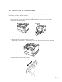
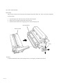
2.3
UNPACKING
If possible, retain the carton and packing materials should the printer be reshipped.
1.
Peel off the top tape to open the four flaps.
2.
Take the toner bottle package, the power cord package, the multi-function feeder (MFF) package, and the
package of user’s manual, floppy disks, cleaning brush, and paper size labels from the carton. Then, take
them from protective bags.
3.
Remove the two upper cushions and housing, then remove the printer out of the carton.
4.
Take the printer from the protective bag.
5.
Set the printer where it is to be installed.
Toner bottle
Upper right
cushion
Printer
Upper left
cushion
Lower left
cushions
Lower right
cushions
Multi-function
feeder (option)
Carton
Binder with :
installation guide,
warranty card and
CD-ROM including user guide and
drivers & NIC
SW)
Power cord
User’s manual
Cleaning
brush
Paper
size labels
Figure 2-1 Shipping Carton and Printer and its Accessories
2 - 2
2.4
INSPECTION AFTER UNPACKING
Visually check the printer exterior. Then, turn power on and check the print quality and printer performance.
See the user’s manual for details of procedures.
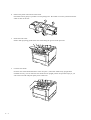
1.
Peel off adhesive tapes from the printer. Open the upper door and remove the two restraint cardboards..
Draw out the paper tray and remove the restraint cardboard and tapes securing the rear paper guide.
Visually check all parts for damage.
2.
Set up the print unit and install the toner bottle.
a.
Remove the protective materials from the print unit.
Remove the protective sheet q. Gently pull the narrow clear tape w until its blue end is visible and
remove it.
w
q
b.
Remove the toner bottle from its envelope.
c.
Fully shake the toner bottle.
2 - 3
2 - 4
d.
Remove the plastic seal from the toner bottle.
Pull off the seal as gently as possible to avoid spilling toner. Be careful not to stain yourself with toner
which is stuck to the seal.
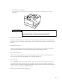
e.
Install the toner bottle.
Slide in both projecting guides of the toner bottle along the grooves of the print unit.
f.
Lock the toner bottle.
Press the toner bottle backward until it clicks into place. (The bottle stands nearly upright when
installed correctly.) Never rotate the toner bottle from an upright position except when empty or you
will cause toner leak and print quality issue could occur.
g.
Close the printer’s upper door.
Press down firmly on the front portion of the upper door and make sure the upper door is locked
completely.
! CAUTION
▲
Be sure to hold the toner bottle while removing the seal to avoid spilling toner.
If you have installed the toner bottle, never remove it from the print
unit until it has no toner, to avoid spilling toner inside the printer.
3.
Load paper in the paper tray.
If the front of the pressure plate is raised, push it down until the plate clicks into place. Fan a paper stack
both ways to prevent sheets from sticking together. Place the paper stack on the paper tray while sliding it
forwards.
4.
Connect the power cord.
Be sure the voltage stated on the manufacturer’s plate on the back of the printer is the voltage supplied in
your area, then connect the AC power cord between the printer and the AC power outlet.
5.
Turn on the power switch.
Make sure the POWER indicator on the control panel lights, printer initialization and warming-up occur,
then the message display indicates READY with the ONLINE indicator lit.
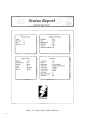
6.
Print a trial page.
Press the READY button to put the printer offline. Then, press the SELF TEST button for more than five
seconds to print the status report shown on the next page. The status report is printed for either the PCL
emulation or the FPS emulation according to the emulation used for last printing. FPS is selected when the
printer is turned on. See the user’s manual for details.
7.
Check the print quality and printer performance.
2 - 5
Figure 2-2 Status Report (FPS Emulation)
2 - 6
CHAPTER 3 TROUBLESHOOTING
This chapter helps you determine the causes and remedies of problems that might occur.
Sections 3.1 and 3.2 are troubleshooting diagrams. Follow the flowchart steps to remedy the problem.
Section 3.3 describes the meaning of the various indicator displays on the control panel. The indicators help
with troubleshooting.
Section 3.4 describes procedures to reset a counter which is used to estimate the life time of a consumable.
Section 3.5 describes miscellaneous printer operations.
Figure 3.1 shows the printer elements and their connections.
3-1
Figure 3-1 Printer Elements and Connections
3-2
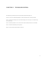
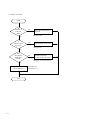
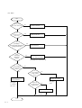
3.1 WHEN THE POWER INDICATOR DOES NOT LIGHT
Start
Is the
POWER lamp on
for a while after
power on?
No
Connect connector.
Yes
Is
connector
disconnected?
No
Yes
Is the
condition still
the same when the
motor connector is
disconnected?
Is
motor activation
sound generated?
Defective power,
controller board,
sensor board, or
control panel
Defective motor or
(and)
controller board
Defective power,
mechanism, or
controller board
See page 4-21 or 24
and other pages of
Section 4.9.1.
No
No
See page 4-21,
24, 25, or 15.
Yes
Yes
Defective
mechanism or
controller board
See page 4-24 and
other pages of
Section 4.9.1.
See page 4-27
or 24.
End
3-3
3.2 WHEN PRINTING QUALITY IS ABNORMAL
(1) Faint
(2) Deep
(3) Clear or blurred black vertical line
P
T
(4) White vertical line
(5) Lacking space at the
top and bottom
(6) Black point, white
point
F
(7) Second printing
(Ghost printing)
T
T
(8) Dirty back/edge
(9) Black
(10) White
P
P
(12) Smudge
P&T
T: Transfer charger unit faulty
P: Print unit faulty
F: Fuser unit expired
Figure 3-2 Abnormal Print Quality
3-4
(11) Blur
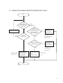
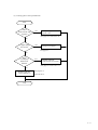
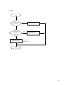
(1) When faint
Start
Is density dial
proper?
No
Adjust density dial.
See page 4-5.
Yes
Does
LCD display
TONER EMPTY?
Yes
Replace toner bottle.
See pages 2-3 to 4.
No
Is
transfer corona
wire dirty?
Yes
Clean transfer corona
wire.
See page 4-8.
No
Does
LCD display
REPLACE
PARTS?
Yes
Replace print unit.
(Unit is at the end of life)
See pages 2-3 and 3-20 to 21.
No
Replace print unit.
(Unit is defective.)
See pages 2-3
and 3-20 to 21.
End
3-5
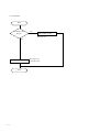
(2) When deep
Start
Is density dial
proper?
No
Adjust density dial.
See page 4-5.
Yes
Replace print unit.
End
3-6
See pages 2-3
and 3-20 to 21.
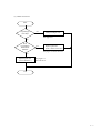
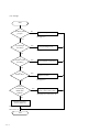
(3) Black vertical line
Start
Is precharger
wire dirty?
Yes
Clean precharger wire.
See page 4-9.
No
Does
LCD display
REPLACE
PARTS?
Yes
Replace print unit.
(Unit is at the end of life)
See pages 2-3 and 3-20 to 21.
No
Replace print unit.
(Unit is defective.)
See pages 2-3
and 3-20 to 21.
End
3-7
(4) White vertical line
Start
Is
window of
laser unit
dirty?
Yes
Clean the window glass of
laser unit.
See page 4-18.
No
Is
transfer corona
wire dirty?
Yes
Clean transfer corona wire.
See page 4-8.
No
Does
LCD display
REPLACE
PARTS?
Yes
Replace print unit.
(Unit is at the end of life)
See pages 2-3 and 3-20 to 21.
No
Replace print unit.
(Unit is defective.)
End
3-8
See pages 2-3
and 3-20 to 21.
(5) Lacking space at the top and bottom
Start
Within
5 mm from the edge
of paper?
Yes
Move printing to area
beyond 5 mm.
See pages 2-3 and 3-20 to 21.
No
Is paper damp
and waved?
Yes
Change to new paper.
See page 2-5.
No
Does
LCD display
REPLACE
PARTS?
Yes
Replace print unit.
(Unit is at the end of life)
See pages 2-3 and 3-20 to 21.
No
Replace print unit.
(Unit is defective.)
See pages 2-3
and 3-20 to 21.
End
3-9
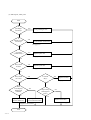
(6) Black point, white point
Start
Is
precharger
wire dirty?
Yes
Clean precharger wire.
See page 4-9.
No
Is
transfer corona
wire dirty?
Yes
Clean transfer corona wire.
See page 4-8.
No
Appeared
synchronously?
No
Replace print unit.
See pages 2-3 and 3-20 to 21.
Yes
Every about
94 mm?
Yes
Replace print unit.
See pages 2-3 and 3-20 to 21.
No
Every about
78.5 mm?
Yes
Is cleaner
dirty?
Yes
Replace cleaner.
See page 4-9.
No
No
Does
LCD display
REPLACE
PARTS?
Yes
Improved by
cleaning heat
roller?
No
Replace print unit.
(Unit is defective.)
Yes
Replace print unit.
(Unit is at the end of life.)
See pages 2-3 and 3-20 to 21.
End
3-10
No
Replace heat roller.
See page 4-19.
(7) Second printing (ghost printing)
Start
Is
transfer corona
wire dirty?
Yes
Clean transfer corona
wire.
See page 4-8.
No
Is
precharger
electrode apart from highvoltage electrode?
Yes
Attach electrode.
No
Is
cleaner dirty?
Yes
Replace cleaner.
See page 4-9.
No
Is
back-up roller
in the fuser unit
dirty?
Yes
No
Does
LCD display
REPLACE
PARTS?
Yes
Improved by
cleaning back-up
roller?
Yes
No
Replace back-up roller.
No
Replace print unit.
(Unit is defective.)
Replace print unit.
(Unit is at the end of life.)
See pages 2-3 and 3-20 to 21.
End
3-11
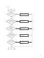
(8) Dirty back / edge
Start
Is paper guide
dirty?
Yes
Clean paper guide.
See pages 4-7 to 8.
No
Is
transfer corona unit
dirty?
Yes
Clean transfer corona unit.
See page 4-8.
No
Is precharger
wire dirty?
Yes
Clean precharger wire.
See page 4-9.
No
Does
LCD display
REPLACE
PARTS?
Yes
Replace print unit.
See pages 2-3 and 3-20 to 21.
No
Is
cleaner dirty?
Yes
Replace cleaner.
See page 4-9.
No
Is heat roller
dirty?
Yes
Clean heart roller in the
fuser unit.
Yes
Clean backup roller in the
fuser unit.
No
Is
backup roller dirty?
No
Replace printer
mechanism assembly.
End
3-12
Note:
If a large amount of toner is spilled or
collected in the paper path, the print unit or
transfer corrona unit may be defective.
(9) Black
Start
Is
precharger wire
dirty?
Yes
Clean precharger wire.
See page 4-9.
No
Is
precharger
electrode apart from highvoltage electrode?
Yes
Attach electrode.
See page 4-9.
No
Does
LCD display
REPLACE
PARTS?
Yes
Replace print unit.
See pages 2-3 and 3-20 to 21.
No
Is
–4 kV supplied
from high-voltage
power?
No
Replace high-voltage
power supply.
See page 4-25.
Yes
Improved by
replacing controller
board?
No
Replace laser unit.
See page 4-18.
Yes
End
3-13
(10) White
Start
Is
connector of
laser unit connected?
No
Connect connector.
See page 4-18.
Yes
Is
transfer corona
wire dirty?
Yes
Clean corona wire.
See page 4-8.
No
Is
precharger
electrode apart from highvoltage electrode?
Yes
Attach electrode.
No
Does
LCD display
REPLACE
PARTS?
Yes
Replace print unit.
(Unit is at the end of life)
See pages 2-3 and 3-20 to 21.
No
Is
+4 kV supplied
from high-voltage
power?
Yes
Replace print unit.
(Unit is defective.)
See pages
2-3 and 320 to 21.
No
Is
+24 V supplied
to high-voltage
power?
No
Yes
Replace main power.
Improved
by replacing highvoltage power.
Yes
No
Replace laser unit.
See page
4-18.
End
3-14
See page
4-21.
(11) Blur
Start
Is
transfer corona
wire dirty?
Yes
Clean corona wire.
See page 4-8.
No
Does
LCD display
REPLACE
PARTS?
Yes
Replace print unit.
(Unit is at the end of life)
See pages 2-3 and 3-20 to 21.
No
Replace print unit.
(Unit is defective.)
See pages 2-3
and 3-20 to 21.
End
3-15
(12) Smudge
Start
Is density dial
proper?
No
Adjust density dial.
See page 4-5.
Yes
Is precharger
wire dirty?
Yes
Clean precharger wire.
See page 4-9.
No
Is
transfer corona
wire dirty?
Yes
Clean transfer corona wire.
See page 4-8.
No
Is
cleaner dirty?
Yes
Replace cleaner.
See page 4-9.
No
Does
LCD display
REPLACE
PARTS?
Yes
Replace print unit.
(Unit is at the end of life)
See pages 2-3 and 3-20 to 21.
No
Replace print unit.
(Unit is defective.)
See pages 2-3
and 3-20 to 21.
End
3-16
3.3 ERROR AND STATUS MESSAGES
This printer displays error and status messages on the LCD of the control panel. 16 characters by 2 lines of
messages indicate information on errors and statuses in detail for maintenance personnel. The printer has also
four indicators to display basic statuses: power-on, online, data presence in buffer, and error occurrence. The
MarkVision and PPMENU utility programs can also indicate these messages on the computer’s monitor.
This section lists these messages into the following three groups.
• Error messages
• Action-required status messages
• Printer status messages
3.3.1
Error Messages
Errors refer to a problem or condition which requires maintenance personnel to take an action. The printer
shows errors by using the ERROR indicator and the message display of the control panel. Table 3-1 lists the
error messages, explains causes, and suggests solutions. However, a fatal error in the controller or mechanism
cannot be cleared by the user. Generally, other errors can be cleared by the user.
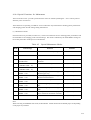
Table 3-1 Error Messages
Message
Causes and solutions
BD CYCLE ERROR
Cause: Malfunction in the laser unit
Solution: If the error recurs, consult your dealer for service.
Cause: Communication error
Solution: Press the CONT. button and select the correct settings of the serial
interface using the control panel setup mode.
Cause: Incomplete closing of upper door
Solution: Close the upper door.
Cause: Incomplete locking of paper guide inside the rear stacker
Solution: Lock the paper guide.
Cause: Incomplete closing of duplex unit
Solution: Close the duplex unit.
Cause: Malfunction in the fuser unit
Solution: If the error recurs, consult your dealer for service.
Cause: Incorrect SIMM card (optional emulation or font) installed
Solution: Press the CONT. button.
Cause: FPS job timeout
Solution: Press the CONT. button.
Cause: Paper mismatch occurred.
Solution: Set the specified tray to the correct paper size specified.
Cause: Paper was not inserted into the manual feed slot in the prescribed
time.
Solution: Press the CONT. button.
Cause: Memory overflow error
Solution: Press the CONT. button.
COMM.ERROR
COVER OPEN 1
COVER OPEN 2
COVER OPEN 3
FUSER FAILURE
INVALID SIMM
JOB TIMEOUT
LOAD MFF size or
LOAD TRAYn size
MANUAL TIMEOUT
MEMORY OVER FLOW
(To be continued)
3-17
Table 3-1 Error Messages (Continued)
Message
Causes and solutions
MEMORY SHORTAGE
Cause: Insufficient memory
Solution: Add RAM board.
Cause: No MFF installed
Solution: Install the MFF.
Cause: Malfunction in the feed motor, etc.
Solution: If the error recurs, consult your dealer for service.
Cause: No print unit is installed.
Solution: Install the print unit.
Cause: Incomplete in extracting compressed data
Solution: Press the CONT. button.
Cause: Paper jam in the specified position
Solution: Clear the jammed paper from the following area:
0: Pick roller, 1: Entry to paper path
2: Paper path, 3: Ejection from paper path, 4: Duplex unit
Cause: A PostScript error
Solution: If the error recurs, consult your dealer for service.
Cause: Paper out in the specified paper source
Solution: Supply paper.
Cause: Paper stacker full
Solution: Remove paper from the paper stacker.
Cause: A system error on the controller board
Solution: If the error recurs, consult your dealer for service.
Cause: Paper tray installed incorrectly
Solution: Install the paper tray.
Cause: Toner runs out.
Solution: Replace toner bottle and cleaner.
MFF NOT INSTALL
MOTOR FAILURE n
NO PROCESS UNIT
OVERRUN ERROR
PAPER JAMn
PS ERROR mn
Source PAPER OUT
STACKER FULL
SYSTEM ERROR n
TRAYn MISS SET
TONER EMPTY
3.3.2
Status Messages
Status messages in this section refer to normal conditions.
Table 3-2 lists status messages referring to conditions that require the user to take an action. It explains causes
and suggests solutions. Table 3-3 lists printer status messages referring to conditions which generally require no
action by the user, and explains their meaning. These tables do not include messages in menu mode.
Table 3-2 Action-required Status Messages
Message
Causes and solutions
INSERT size
Cause: Printer is ready for paper.
Solution: Put paper into manual feed slot.
Cause: Toner runs short.
Solution: Prepare new toner bottle and cleaner.
Cause: Print unit is near end.
Solution: Replace print unit.
Note: Enter menu mode and select Clear Warning. After replacement, be sure
to press ENTER to perform Clear Warning.
READY TONER LOW & PAD
READY REPLACE PARTS
3-18
Table 3-3 Printer Status Messages
Message
Meaning
FORM FEED
The printer displays this message when you press FORM FEED with the
DATA indicator off. The printer is printing data remaining in buffer.
The printer is initializing. This message appears whenever you turn on the
printer.
The printer displays this message when you press RESET MENU for five or
more seconds. This reset returns parameter settings in the menu to their
factory defaults except for interface settings as well as clears error latches,
buffered data, and temporary soft fonts.
The printer displays this message when you press PRINT FONT for five or
more seconds. The printer is printing the font report.
The printer is ready to print.
The printer displays this message when you press RESET for five or more
seconds. This reset clears error latches, buffered data, and temporary soft
fonts.
The printer displays this message when you press SELF TEST for five or more
seconds. The printer is printing the status report.
The printer is warming up to its operating temperature.
<<<INITIALIZE>>>
MENU RESET
PRINT FONT
READY
RESET
SELF TEST
WARMING UP
Warning Messages
This printer counts the number of the printed sheets to estimate the life of the consumables (print unit). The
printer displays the following warning message when and after the count reaches a predetermined value. Note
that this value does not necessarily indicate the actual life. The print quality may remain satisfactory to users for
some time after this warning appears.
READY
REPLACE PARTS
When the warning message is displayed, press the READY button to put the printer offline and press the MENU
button to enter menu mode. The Warning message appears, indicating the expired unit by an asterisk. When
the print unit is expired, the message is:
<CLEAR WARNING>
PRINT UNIT*
When the print unit is replaced, be sure to reset the counter according to Section 3.4.
3-19
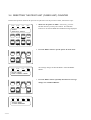
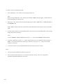
3.4 RESETTING THE PRINT UNIT (FUSER UNIT) COUNTER
Perform this operation whenever the print unit is replaced to reset the print unit counter, follow these steps:
POWER
ONLINE
DATA
ERROR
READY
REPLACE PARTS
READY
FORM
FEED
CONT.
TRAY
SELECT
ENTER
–
RESET
MFF
PAPER SIZE
SELF
TEST
PRINT
FONT
READY
FORM
FEED
MENU
+
CONT.
TRAY
SELECT
ENTER
–
RESET
MFF
PAPER SIZE
SELF
TEST
PRINT
FONT
ONLINE
DATA
1. Make sure the printer is offline. If necessary, press the
READY button to put the printer offline. The ONLINE
indicator is off with the REPLACE PARTS message displayed.
+
MENU
RESET
MENU
2. Press the MENU button to put the printer in menu mode.
RESET
MENU
POWER
ERROR
The message changes to SETUP MENU PAGE FORMAT
MENU.
SETUP MENU
PAGE FORMAT MENU
READY
FORM
FEED
CONT.
TRAY
SELECT
ENTER
–
RESET
MFF
PAPER SIZE
SELF
TEST
PRINT
FONT
ONLINE
DATA
MENU
+
RESET
MENU
POWER
SETUP MENU
CLEAR WARNING
3-20
ERROR
3. Press the MENU button repeatedly until the lower message
changes to CLEAR WARNING.
4. Press the ENTER button to select this function.
READY
FORM
FEED
CONT.
TRAY
SELECT
ENTER
–
RESET
MFF
PAPER SIZE
SELF
TEST
PRINT
FONT
+
MENU
RESET
MENU
POWER
ONLINE
DATA
ERROR
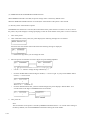
<CLEAR WARNING>
PRINT UNIT
*
READY
FORM
FEED
CONT.
TRAY
SELECT
ENTER
–
RESET
MFF
PAPER SIZE
SELF
TEST
PRINT
FONT
ONLINE
DATA
+
MENU
The message changes to <CLEAR WARNING> PRINT UNIT
*. The asterisk means that the print unit is expired.
5. Press the ENTER button again to execute the function. The
asterisk disappears, indicating the counter is reset.
RESET
MENU
POWER
ERROR
<CLEAR WARNING>
PRINT UNIT
READY
FORM
FEED
CONT.
TRAY
SELECT
ENTER
–
RESET
MFF
PAPER SIZE
SELF
TEST
PRINT
FONT
POWER
ONLINE
MENU
+
RESET
MENU
DATA
6. Press the READY button to return the printer online. The
ONLINE indicator lights up without the REPLACE PARTS
message
ERROR
READY
Important:
After the reset operation, check the status report or the PPMENU’s main menu to make sure that the
Warning Message is cleared.
3-21
3.5 OTHERS
The printer performs the following controls not under commands from the computer.
(1) Fan control
The fan 1 stops after three minute has elapsed since the last printing. The fan 2 stops after ten minutes has
elapsed since the last printing.
(2) Initial control of motor
At initialization, the motor rotates when the temperature of the heater reaches 100°C and stops when the
temperature reaches 170°C, then the printer goes ready to print.
(3) Heat roller temperature control
The heat roller temperature is reduced to 100°C from 170°C when printing does not occur for one minute.
Power supply to the heat roller is stopped after additional one minute has elapsed without printing.
3-22
CHAPTER 4
MAINTENANCE
This chapter covers the maintenance (cleaning, lubrication, inspection, and adjustment) required for levels 1
and 2 defined in Section 4.4.
4.1 GENERAL
Using the latest in electronic technology, the Laser Printer LN15 offers high reliability and ease of maintenance. The number of parts requiring lubrication and/or adjustment has been reduced.
The LN15 printer has a self diagnostic function which briefly indicates the type of error using the indicators on
the control panel if the printer malfunctions.
This printer has the status report function to help indicate whether an error is due to the printer or the host
computer. This function is useful for testing printer performance after an error recovery.
4.2 GENERAL PRECAUTIONS
The following precautions will help prevent damage to the LN15 page printer.
• Do not connect or disconnect connectors or printed circuit boards while the power is turned on.
• Use screwdrivers, pliers, and other tools appropriate to the parts to be replaced. Do not leave screws or parts
inside the printer.
• Use only the specified type of oil, grease, and cleaner.
• Power should be turned off before beginning any parts replacement.
• Be careful not to cause damage to the print unit by touching the surface of the OPC drum with fingers, metal,
or anything. Do not set the print unit in light for extended periods of time.
4-1
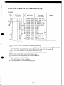
4.3 MAINTENANCE TOOLS
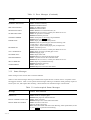
Table 4-1 lists the tools required for maintenance.
Table 4-1 Maintenance Tools
No.
4-2
Tool Name
Q’ty
Remarks
1
Screwdriver (Phillips)
1
For M3 and M4
2
Screwdriver (standard)
1
For M3
3
Screwdriver (standard)
1
For M4
4
Long-nose pliers
1
5
Diagonal cutting pliers
1
4.4 MAINTENANCE LEVELS
Maintenance for the LN15 page printer is divided into two levels.
Level 1
Level 1 maintenance can be done by the printer user. It includes cleaning and consumables replacement only.
Level 2
Level 2 maintenance includes level 1 items (cleaning) plus replacement of PC boards, electrical units, and
mechanical subassemblies.
4.5 PREVENTIVE MAINTENANCE
No scheduled maintenance is required. However, a clean printer has a longer service life and MTBF.
Note:
Clean the corona wire of the transfer charger unit and the precharger wire of the print unit whenever the
toner bottle or the print unit is replaced.
4-3
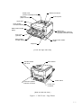
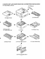
4.6 PARTS DRAWINGS
This section shows the locations of the basic components.
Shade cover
(cleaner assembly inside)
Stacker-full sensor
Top cover
(Paper stacker)
Control panel
Upper door
Paper guides
for manual feeding
Multi-function feeder
(MFF)
Slide cover
(Font/emulation card slot
and RAM card slots inside)
Front cover
(opened)
Paper guides
for stack feeding
Multi-function feeder
cable
Paper tray
Front and right side view
Rear stacker
Interface board
slot cover
Power switch
Centronics parallel
interface connector
Power cord
connector
Rear and Left Side View
Figure 4-1 Basic Components
4-4
Toner bottle
Print density dial
Print unit
Interior with the Upper Door Open
Figure 4-1 Basic Components—Continued
4-5
4.7 PARTS THAT MUST NOT BE DISASSEMBLED
Table 4-2 lists components that are not to be disassembled.
Table 4-2 Parts That Must Not be Disassembled
No.
4-6
Parts Name
Specification
Remarks
1
Print unit
CA02758-E400
LN15X-AB (OPC Drum)
Allowed only to separate OPC drum
from developing unit
2
Toner bottle
CA02758-E300
LN15X-AA
2 Bottles toner cartridges
3
Heat roller unit
CA04040-C941
LN15-AD (Fusing Unit)
4
Transfer charger unit
CA04040-F450
For 120 VAC model
4.8 LEVEL 1 MAINTENANCE
Level 1 maintenance includes only cleaning and consumables replacement that can be performed by the operator
without removing any cover.
4.8.1
Cleaning
First, check the inside of the printer for paper particles, dust, and other foreign matter. Remove them, if any, as
explained in the table shown below. If replacement is necessary, see the procedures explained in this chapter.
The areas to be cleaned and the procedures for cleaning are listed in Table 4-3.
Table 4-3 Cleaning
No.
Area to be cleaned
Specification
Remarks
1
Base frame
Remove paper particles, toner, and dust.
Use a damp cloth.
2
Pressure roller
Open the upper door . Then, wipe the roller
with a cloth dampened with ethyl alcohol or
equivalent while rotating it by hand.
Be careful not to damage the
roller. Be sure rollers are
dry before operation.
3
Paper path
Remove paper dust and fragments.
4
Corona wire
Remove toner from the tungsten wire and
chassis using the cleaning tool supplied. See
Figure 4-3.
Be careful not to break the
wire.
Replace the transfer charger unit if it is very
dirty.
5
Precharger wire
Remove toner from the tungsten wire and
chassis using the cleaning tool supplied. See
Figure 4-4.
Be careful not to break the
wire.
Replace the print unit if it is very dirty. See
Chapter 5 of the User’s Manual.
4-7
Figure 4-2 Cleaning the Paper Path
Cleaning tool
Figure 4-3 Cleaning the Corona Wire
4-8
Cleaning tool
Figure 4-4 Cleaning the Precharger Wire
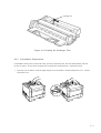
4.8.2
Consumables Replacement
Consumables of this printer are the toner bottle, print unit, and cleaner pad. The toner bottle and the print unit
are easy to replace. So, this section explains how to replace the cleaner pad only. Follow these steps:
1.
Open the cover as follows: Push the engraved portion on the stacker to unlock and open the cover. Lift the
front of the cover.
4-9
Remove the cleaner as follows: Push down the handle of the cleaner and push forward it to unlock the
cleaner. Slide the cleaner to the left and take its right end out of the opening, and then the left end.
3.
Mount a new cleaner pad on the cleaner as follows: Push the lock lever to unlock the cleaner pad to remove
the cleaner pad from the cleaner. Slide the cleaner pad to the right and separate it from the cleaner. Put the
new cleaner pad on the cleaner and slide the cleaner pad into the locked position.
4.
Install the cleaner in the printer as follows: Grasp the handle of the cleaner and put the left end of the
cleaner into the opening, and then the right end. Push down the top of the handle and pull it towards you to
lock the cleaner. Close the cover.
4-10
2.
4.9 LEVEL 2 MAINTENANCE
Level 2 maintenance includes maintenance such as lubrication and parts replacement. Level 1 maintenance
should also be performed when level 2 maintenance is performed.
4.9.1
Replacement
Precautions
a.
Keep assembly areas clean.
b.
Turn off the power to the printer and disconnect the power cord and interface cable before disassembly or
assembly.
c.
Follow the procedures carefully. Do not loosen any parts that are not to be disassembled.
d.
Store disassembled parts in a clean place where they will not get lost.
e.
Check parts for correct numbers and shape after replacement.
f.
Reassemble the printer in the reverse order of disassembly. Be sure that all connectors are connected
correctly.
g.
Do not stand the printer as shown below with the control board installed. If not so, the parallel interface
connector may be damaged.
Front
Top
Parallel interface
connector
4-11
(1)
Upper cover replacement
Removal
1. Open the upper door.
2. Remove three screws.
3. Remove one screw to remove the rear cover.
4. Remove side cover R and side cover L.
5. Remove three screws to remove the shield plate.
Upper door
Upper cover
Shield plate
Side cover R
Side cover L
4-12
Disconnect the control panel connector and the volume board connector.
Control panel connector
Volume board connector
6.
Bottom
Front
4-13
7.
Lift the upper cover in an upward direction to remove it while pressing four claws on the left and right of the
upper cover using a standard screw driver as shown below:
Installation
Reverse the removal procedure.
4-14
(2)
Control panel replacement
Removal
1. Remove the upper cover. (See Item (1))
2. Remove the control panel while pressing the two claws on the left and right of the panel, using a
standard screw driver.
Installation
Reverse the removal procedure.
4-15
FAN1 (Blue)
FAN2 (White)
Connectors and Cable Connections of the Control Board (Right Side View)
Bottom
Front
4-16
Cable Routes of the Pick-up Motor and the Cover-open Switch (Left Side View)
Front
Bottom
4-17
(3)
Laser unit replacement
Removal
1. Remove the upper cover. (See Item (1))
2. Disconnect the connector from the laser unit.
3. Remove three screws to remove the frame ground cover and the laser unit.
(There is a glass window
on the bottom of this side.)
(Frame ground cover is removed from the top of the laser unit)
Installation
Reverse the removal procedure.
4-18
(4)
Fuser unit replacement
WARNING :
WAIT 5 MINUTES AFTER POWER DOWN BEFORE REMOVING THE FUSER UNIT
Removal
1. Open the shade cover. (See Section 4.8.2 Consumables Replacement.)
2. Remove the cleaner assembly. (See Section 4.8.2 Consumables Replacement.)
3. Remove side cover R. (See Item (1) Upper cover replacement.)
4. Remove the shield plate. (See Item (1) Upper cover replacement.)
5. Disconnect the connector (for FAN2) from the control board.
6. Remove the rear cover. (See Item (1) Upper cover replacement.)
7. Remove four screws from the rear of the unit to draw out the subassembly of the power supply board
and the fuser unit.
Notes
1. The power supply board and the fuser unit are hot immediately after printing.
2. Remove the power supply board and the fuser unit carefully.
8.
Remove the rear stacker
4-19
9.
Disconnect the two connectors while pressing the connector lock with a standard screw driver as shown
below. (The following illustration shows the side that faced to the front of the printer when the unit was
installed.)
10. Remove two screws from the front of the unit to separate the fuser unit from the power supply board.
11. Remove the power supply board from the subassembly. (See Item (5) Power supply board replacement.)
12. Remove FAN2 and gears 1 to 6 from the subassembly. (See Item (7) FAN2 replacement.)
Remaining is the fuser unit.
Note:
Do not disassemble the fuser unit itself.
Installation
Reverse the removal procedure.
Notes:
1. Return gears 1 to 6 to the original positions and hold them by installing the FAN2 mounting plate.
2. Fasten FAN2 on the plate so that the air flow arrow is in the outward direction. (See Item (7) FAN2
replacement.)
Gear 5
Gear 4
Gear 6
Gear 1
4-20
Gear 2
Gear 3
(5)
Power supply board replacement
Removal
1. Remove side cover R and the shield plate. (See Item (1) Upper cover replacement.)
2. Disconnect the connector (for FAN2). (See Item (4) Fuser unit replacement.)
3. Remove the subassembly of the fuser unit and the power supply board. (See Item (4) Fuser unit
replacement.)
4. Turn the subassembly upside down
5. Remove six screws which fasten the cover.
6. Disconnect the two connectors (for the fuser unit) then the connector (for the sensor board) and remove
the power supply board.
Power supply board
Installation
Reverse the removal procedure.
4-21
(6)
FAN 1 replacement
Removal
1. Remove the upper cover. (See Item (1) Upper cover replacement.)
2. Disconnect the connector from FAN1.
3. To remove FAN1, lift it at an angle while pressing the lower mounting plate with a standard screw
driver as shown below.
FAN 1
Installation
Reverse the removal procedure.
Note:
Install the FAN1 so that the labelled air flow arrow is in the upward direction.
Air flow
Marks
4-22
(7)
FAN 2 replacement
Removal
1. Remove the subassembly of the fuser unit and the power supply board. (See Item (4) Fuser unit
replacement.)
2. Remove two screws to remove FAN2 from the side of the subassembly.
Power supply unit
FAN 2
Installation
Reverse the removal procedure.
Note:
Install the FAN2 so that the labelled air flow arrow is in the outward direction.
Air flow
Marks
4-23
(8)
Control board replacement
Removal
1. Remove the paper tray.
2. Remove side cover R and the shield plate. (See Item (1) Upper cover replacement.)
3. Disconnect the following all connectors:
CNFAN1, CNFAN2, CNERS, CNTN, OPT, CNMM, CNRMP, CNCSTA, CNMFF, CNPS1, CNOP,
and CNSTKF
4. Remove seven screws and disengage the lower hook to remove the control board.
Control board
Installation
Reverse the removal procedure.
Notes:
1. Engage the control board securely with the lower hook and screws.
2. There is a connector on the back side of the control board, which connects to the sensor boar connector.
When installing the control board, lift it into place so that the control board connector faces the sensor
board connector.
3. To CNFAN1 (left side), connect the connector with red and black cables from the upper fan. To
CNFAN2 (right side), connect the connector with blue and red cables from the lower fan.
4-24
(9)
High-voltage power supply board and sensor board replacement
Removal
1. Remove the paper tray.
2. Remove side cover R and the shield plate. (See Item (1) Upper cover replacement.)
3. Remove the control board. (See Item (8) Control board replacement.)
4. Remove four screws from the bottom of the printer to remove.
5. Disconnect the connector (cable from the power supply) and pull out the mechanism board from the
control board.
4-25
6.
7.
Remove five screws to remove the sensor board assembly.
Remove four screws to remove the high-voltage power supply board.
Sensor
board
High-voltage
power supply board
Installation
Reverse the removal procedure.
Notes:
1. When installing the sensor board, observe the order of fastening screws.
2. When installing the mechanism board, take care so that the cable does not overlap the four spring
electrodes on the bottom left of the printer mechanism.
3. After connecting the connector (cable from the power supply board), install the mechanism board while
matching the four screw positions.
4-26
(10) Main motor replacement
Removal
1. Remove the upper cover. (See Item (1) Upper cover replacement.)
2. Remove the control board. (See Item (8) Control board replacement.)
3. Remove FAN1. (See Item (6) FAN 1 replacement.)
4. Remove four screws to remove the main motor unit.
Main motor unit
5.
Remove four screws and disconnect the cable to remove the main motor.
Installation
Reverse the removal procedure.
4-27
(11) Pick-up motor replacement
Removal
1. Remove side cover L. (See Item (1) Upper cover replacement.)
2. Remove the subassembly of the sensor board and the high-voltage power supply board. (See Item (9)
High-voltage power supply board and sensor board replacement.)
3. Remove two screws to remove the pick-up motor.
Pick-up motor
Installation
Reverse the removal procedure.
4-28
(12) Pick-up roller replacement
Removal
1. Remove the paper tray.
2. Remove side cover L. (See Item (1) Upper cover replacement.)
3. Remove the screw from the pick-up roller shaft FG plate and remove the FG plate.
4. Remove the bearing using a standard screw driver.
5. Pull the pick-up roller shaft out approximately 50 mm to remove the pick-up roller.
Note:
Do not pull out the shaft completely.
FG plate
Pick-up roller
4-29
Installation
Reverse the removal procedure.
Note:
When putting the pick-up roller on the shaft, face the tapered rib of the roller toward the pick-up motor. The
following shows the relative position of pick-up roller and pick-up motor viewed from the bottom.
Pick-up motor
Tapered rib
Pick-up roller
4-30
(13) Resist motor replacement
Removal
1. Remove the control board. (See Item (8) Control board replacement.)
2. Remove two screws to pull out the resist motor.
Resist motor
Installation
Reverse the removal procedure.
Reference:
The resist motor derives from the resist roller (in contact with the feed roller) which momentarily blocks the
paper feed from the pick-up roller to align the paper.
4-31
(14) Paper feed roller replacement
Removal
1. Remove the upper cover and side covers L and R. (See Item (1) Upper cover replacement.)
2. Remove three screws, disengage three hooks, and disconnect the toner sensor connector to remove the
front frame.
Front frame
3.
4.
5.
Remove the right and left springs of the resist roller and lift the resist roller to remove it.
Peel off the two guide sheets (Mylar films). Be sure to clearly remove the remaining substance of the
double-sided adhesive tape.
Disengage the bearing phase shift levers at the both ends of the paper feed roller using a standard
screwdriver and raise the levers upwards to remove the paper feed roller.
Spring
Bearing
Resist roller
4-32
Guide sheets
6.
7.
Cut the hook of the gear at the right end of the paper feed roller using a diagonal cutting pliers.
Move the paper feed roller to the left and pull out the roller from the left end.
Paper feed roller
Bearing
Bearing
Gear
Hook
Installation
Reverse the removal procedure.
Notes:
1. When installing the paper feed roller:
a. Fit one bearing to the left end (end without a D-cut) of the paper feed roller.
b. Insert the right end D-cut of the paper feed roller into the hole of the other bearing then the hole of a
new gear until the gear is caught by the hook.
c. Insert the bearings into guide grooves on the base frame with the bearing phase shift levers set
upwards. Then, turn the bearing levers to the initial state positions to secure the bearings to the base
frame.
2. Adhere new guide sheets on the base frame: longer one to the left area and shorter one to the right area.
Make sure that there is no clearance between the adhesive tape and the positioning edge as shown on
the next page.
4-33
Guide sheets
Guide sheets
Rear
Positioning edge
Front
4-34
Positioning edges
(15) Transfer charger unit replacement
Removal
1. Open the upper door.
2. Remove the transfer charger unit holding block at the left side of the transfer charger unit using a screw
driver.
3. Open the claw on the left side of the base frame then lift the left side of the transfer charger unit using a
screw driver to pull out the transfer charger unit toward the left side.
Note:
Be careful not to break the wire.
Holding block
Transfer charger
unit
Installation
Reverse the removal procedure.
Note:
The inside is hot immediately after printing.
4-35
(16) Cover-open switch replacement
Removal
1. Remove the subassembly of the sensor board and the high-voltage power supply board. (See Item (9)
High-voltage power supply board and sensor board replacement.)
2. Disconnect the connector from the cover-open switch.
3. Disengage the two claws of the left guide (for the print unit) and pull the left guide out in an upward
direction to remove it.
4. Remove the cover-open switch.
Cover-open switch
Hooks
Installation
Reverse the removal procedure.
4-36
(17) Volume board replacement
Removal
1. Remove the control board. (See Item (8) Control board replacement.)
2. Remove the screw to remove the volume board from the bottom of the frame.
Note:
Use a short Phillips screwdriver.
Installation
Reverse the removal procedure.
4-37
(18) Stacker-full sensor board (SFS board) replacement
Removal
1. Remove the upper cover. (See Item (1) Upper cover replacement.)
2. Remove the cable from the stacker-full sensor.
3. Remove the screw at the rear of the board.
Installation
Reverse the removal procedure.
4-38
(19) Frame-2 assembly replacement
Removal
1. Remove the upper cover. (See Item (1))
2. Remove the stacker-full sensor board. (See Item (18))
3. From the rear of the printer, draw out the paper guide.
4. Push outward the two hooks on the bottom of the frame-2 assembly to disengage them from the frame
on which the laser unit is also mounted, and then lift the frame-2 assembly to remove it.
Rear view
Frame-2 assembly
! CAUTION
▲
Hook
Frame-2 assembly
Laser unit
Installation
Reverse the removal procedure.
4-39
(20) Multi-function feeder board (MFF board) replacement
Removal
1. Remove side cover R. (See Item (1) Upper cover replacement.)
2. Remove the cable from the MFF board.
3. Remove the screw at the top side of the board.
Installation
Reverse the removal procedure.
4-40
(21) Separator assembly (friction pad holder) replacement
Removal
1. Remove the paper tray from the printer.
2. Place the paper tray upside down and push in the four points of the lower paper guide to release and
remove it.
3. Push in the two hooks of the separator assembly (friction pad holder) to release and remove it.
Remember to keep the spring.
Installation
Reverse the removal procedure.
4-41
(22) Print unit disassembly
Disassembly
The print unit consists of two main parts, developing unit and OPC drum unit. They can be easily separated
from each other.
1.
2.
3.
Open the upper door and remove the print unit from the printer.
Remove the two clamps at both ends of the print unit.
Slide off the OPC drum unit along the grooves on the developing unit.
Developing unit
OPC drum unit
Clamp
Assembly
Connect the OPC drum unit to the developer unit by reversing the procedures for removal.
4-42
4.9.2
Lubrication and Precautions
This section describes the lubrication procedures. The lubrication code is as follows:
2–SG–C–Y
Lubrication cycle (every year)
Lubrication quantity (apply oil thin and evenly)
Lubricant type (Silicon grease)
Item number
1.
Item number
Serial number of lubrication point on the diagram
2.
“
“
“
“
“
3.
Lubricant type
SG:
FG:
SSG:
SSG:
MG:
Lubricant quantity
D:
S:
F:
C:
H:
4.
Silicon grease Molycoat EM30L (Dow Yuning)
Conductive grease FLOIL GE676 (Kanto Kasei)
Silicon grease KF-96H-10000CS (Shin-Etsu Silicon)
Silicon grease G501 (Shin-Etsu Silicon)
Grease Mobile oil + Albania EP grease (1:1 mixing ratio)
One drop
Several drops
Fill wick, case, etc.
Apply oil thin and evenly
One spray
Lubrication cycle
2:
4:
6:
8:
Y:
O:
Every 2 months
Every 4 months
Every 6 months
Every 8 months
Every year
At overhaul
4-43
(1)
Base frame assembly
1-S-GC-O
(Y611)
Item No. Lubricant Lubricant
type
quantity
1
4-44
SGG
C
Lubrication
cycle
O
Part to be lubricated
Y621 bearing sections with 8 mm
diameter of the paper feed roller
Remarks
Apply both bearings.
Do not apply to roller
surface and bearing
sections with 10 mm
diameter.
(2)
Frame L assembly
Item No.
1
2
3
4
5
6
Lubricant Lubricant
type
quantity
SGG
SGG
SGG
SGG
SGG
SGG
C
C
C
C
C
C
Lubrication
cycle
O
O
O
O
O
O
Part to be lubricated
-
Remarks
Y204 gear tooth surface and shaft
Y211 gear tooth surface and shaft
Y212 gear tooth surface and shaft
Y213 gear tooth surface and shaft
Y214 gear tooth surface and shaft
Y215 gear tooth surface and shaft
4-45
(3)
Fuser unit
Item No.
1
2
3
4
5
6
4-46
Lubricant Lubricant Lubrication
type
quantity
cycle
SGG
SGG
SGG
SGG
SGG
SGG
C
C
C
C
C
C
O
O
O
O
O
O
Part to be lubricated
-
Y651 gear tooth surface and shaft
Y662 gear tooth surface and shaft
Y663 gear tooth surface and shaft
Y664 gear tooth surface and shaft
Y665 gear tooth surface and shaft
Y692 gear tooth surface and shaft
Remarks
(4)
Main motor unit
All gear circumference
All gear circumference
All gear circumference
Item No.
1
Lubricant Lubricant
type
quantity
SG
C
Lubrication
cycle
O
Part to be lubricated
Remarks
- Gear tooth surface and shaft (2)
4-47
(5)
Frame-2 assembly
Item No.
1
2
3
4-48
Lubricant Lubricant Lubrication
type
quantity
cycle
SGG
SGG
SGG
C
C
C
O
O
O
Part to be lubricated
- Y684 gear tooth surface and shaft
- Y685 gear tooth surface and shaft
- Y692 gear tooth surface and shaft
Remarks
(6)
Guide assembly
Item No.
1
2
Lubricant Lubricant
type
quantity
SGG
SGG
C
C
Lubrication
cycle
O
O
Part to be lubricated
Remarks
- Y692 gear tooth surface
- Y692 shaft
4-49
(7)
Feed-2 assembly
Item No.
1
4-50
Lubricant Lubricant
type
quantity
SGG
C
Lubrication
cycle
Part to be lubricated
O
- Bearing and edge of CA02758-Y682
Remarks
(8)
Gear box assembly
Item No.
1
Lubricant Lubricant
type
quantity
SG
C
Lubrication
cycle
O
Part to be lubricated
Remarks
- Gear tooth surface and shaft (2)
4-51
(9)
Gear box lever assembly
Lubricant Lubricant Lubrication
Item No. type
quantity
cycle
1
4-52
SGG
C
O
Part to be lubricated
- Y272 gear shaft
Remarks
(10) Developing unit
Item No.
1
2
3
4
5
Lubricant Lubricant
type
quantity
SSG
SSG
SSG
SSG
SGG
C
C
C
C
C
Lubrication
cycle
O
O
O
O
O
Part to be lubricated
-
Remarks
Gear bore (Y336)
Gear bore (Y310)
Gear bore (Y311)
Gear bore (Y312)
Gear bore (Y307)
4-53
Item No.
6
4-54
Lubricant Lubricant Lubrication
type
quantity
cycle
SSG
C
O
Part to be lubricated
- Bearing slide (Y308)
Remarks
Two places
(11) Magnet roller bracket assembly
Item No.
1
Lubricant Lubricant
type
quantity
MG
C
Lubrication
cycle
O
Part to be lubricated
- Y322 bore
Remarks
Two places
4-55
(12) Heat roller subunit
Item No.
1
2
4-56
Lubricant Lubricant Lubrication
type
quantity
cycle
SGG
MG2
C
C
O
O
Part to be lubricated
- Y538 gear tooth surface
- Y538 gear shaft
Remarks
(13) Heat roller base unit
Item No. Lubricant Lubricant
type
quantity
1
SGG
C
Lubrication
cycle
O
Part to be lubricated
- G530 bearing (both sides)
Remarks
Do not apply to the
rubber roller.
4-57
4.10 DIAGNOSTICS
4.10.1 Printing the Status Report
This function prints a page that summarizes printer option settings and lists samples of resident fonts. The
option settings include information on interface parameters, available emulations, characteristics of the selected
font, and firmware and font versions. See Figure 4-5. The status report includes a warning message when some
of consumables reach their end of life.
The status report printing can be used in place of the test print mode (see Section 4.10.4). The method of
operation and sample of results are shown below.
Operation:
1.
Make sure that the message display indicates READY with the ONLINE and DATA indicators off.
2.
Press the SELF TEST button for five or more seconds.
The message changes to SELF TEST with the DATA indicator flashing and the status report begins
printing. After printing, the printer returns to the original state.
Status report printing can also be started by PPMENU. See the last section in this chapter.
Pressing the PRINT FONT button instead of the SELF TEST button starts printing the font report that lists all
available fonts. See Figure 4-6.
Note:
The status and font reports are printed for either the PCL emulation or the FPS emulation according to the
emulation used for last printing. FPS is selected when the printer is turned on. The FPS font report does
not include ESC sequences to print fonts.
4-58
Figure 4-5 Status Report (FPS Emulation)
4-59
Figure 4-6 Font Report (FPS Emulation)
4-60
4.10.4 Special Functions for Maintenance
The Laser Printer LN15 provides special functions which are started by holding the + and – buttons pressed
when the power is turned on.
These functions are specially provided for service technicians only and useful for checking printer performance
and changing printer internal settings during maintenance.
(1) Maintenance modes
Eleven functions are provided (see Table 4-5). The first four functions are for checking printer performance and
the remainder are for changing printer internal settings. The mode is indicated by the TEST PRINT message on
the control panel after normal power-on initialization.
Table 4-5
Mode
LCD message
Special Maintenance Modes
Function
Remarks
1
TEST PRINT
Start continuous self-test printing
2
EEPROM CLEAR
Clear EEPROM for controller
2-1
EEPROM CLEAR
Extension
Clear particular area of EEPROM for
controller
Factory use only
3
EEPROM CLEAR
(MECHA CONT. 1)
Clear EEPROM for engine 1
Factory use only
4
EEPROM CLEAR
(MECHA CONT. 2)
Clear EEPROM for engine 2
Factory use only
5
TOP ADJUST (TRAY)
PARA = XX
Adjust top edge of print area of paper
fed from paper tray
Factory use only
6
TOP ADJUST (MANU)
PARA = XX
Adjust top edge of print area of paper
fed from manual feed slot
Factory use only
7
RESIST ADJUST
PARA = XX
Adjust resist motor speed
Factory use only
8
LEFT ADJUST FACE
PARA = XX
Adjust left edge of print area of paper
face
Factory use only
9
LEFT ADJUST BACK
PARA = XX
Adjust left edge of print area of paper
back
Factory use only
10
ENGINE MODE
PARA = XX
Send engine command and display
return value from mechanism controller
Factory use only
11
ENGINE MAINTE.
Start maintenance mode
Factory use only
Note:
When executing an EEPROM clear mode, the PrintPartner 14ADV determines the default paper size depending
on the paper tray installed.
4-61
(2) How to execute a maintenance mode
1.
Press and hold the + and – buttons while turning the printer on.
Note:
Be sure to keep holding the + and – buttons until the TEST PRINT message appears. It takes about one
minute (depending on warm-up time).
2.
Release the + and – buttons when the message display shows TEST PRINT after <<<INITIALIZE>>>
and WARMING UP.
TEST PRINT is the first function in maintenance mode and indicates that the printer enters maintenance
mode .
3.
To select another function, press the MENU button. Each time you press the MENU button, the message
display shows the next function.
Note:
To select EEPROM CLEAR Extension, press the + or – button when EEPROM CLEAR is shown.
4.
To change a parameter, press the + or – button. Some functions involve a parameter which is shown as
PARA = XX in the bottom line of the message. Each time you press the + or – button, the value XX
increases or decreases.
5.
To execute a function, press the ENTER button when the desired function is shown.
Notes:
1.
To stop or quit the maintenance mode, turn power off.
2.
Never execute function modes 2-1 to 2-11 that are for factory use only. The user’s setup data or
mechanism-dependent adjustments will be lost.
4-62
(3) Information printed in test print mode
The first page of the test print in maintenance mode contains the following information in the second to eighth
lines of text before a continuous print of ASCII text.
VALUE 1
VALUE 3
VALUE 4
VALUE 5
VALUE 2
“#$%’()*+,/0123456789:;<=>?@ABCDEFGHIJKLMNOPQRSTUVWXYZ[\]^_`abcdefghijklmnopqrst
[00000001519] [0000000002]:;<=>?@ABCDEFGHIJKLMNOPQRSTUVWXYZ[\]^_`abcdefghijklmno
[DIGITAL Laser P] 56789:; <=>?@ABCDEFGHIJKLMNOPQRSTUVWXYZ[\]^_`abcdefghijklmnopq
[MFG: DIGITAL;] 3456789:;<=>?@ABCDEFGHIJKLMNOPQRSTUVWXYZ[\]^_`abcdefghijklmnop
[CMD: NDAP,PJL,PCL,PS;]<=>?@ABCDEFGHIJKLMNOPQRSTUVWXYZ[\]^_`abcdefghijklmnoqr
[MDL: Laser printer LN15 ]<=>?@ABCDEFGHIJKLMNOPQRSTUVWXYZ[\]^_`abcdefghijklmnoqr
[00008741] 2345678:;<=>?@ABCDEFGHIJKLMNOPQRSTUVWXYZ[\]^_`abcdefghijklmnopqrstuvw
)*+,-./0123456789:;<=>?@ABCDEFGHIJKLMNOPQRSTUVWXYZ[\]^_`abcdefghijklmnopqrstuvwxy
*+,-./0123456789:;<=>?@ABCDEFGHIJKLMNOPQRSTUVWXYZ[\]^_`abcdefghijklmnopqrstuvwxyz
+,-./0123456789:;<=>?@ABCDEFGHIJKLMNOPQRSTUVWXYZ[\]^_`abcdefghijklmnopqrstuvwxyz{
• [VALUE 1]: Total number of printed pages
Maximum = 16,777,216 (The maximum value returns to zero.)
• [VALUE 2]: Total time of rotation of the print unit’s drum. This value is 1/5120 of the actual time (second).
Maximum
= 63 (The maximum value remains unchanged.)
= 322,560 seconds
• [VALUE 3]: Printer name (used by PJL command)
DIGITAL Laser P ===> DIGITAL Laser Printer LN15
• [VALUE 4]: Device ID for bi-directional Centronics
DIGITAL Laser P
Device ID
[MFG:DIGITAL;]
[CMD: NDAP,PJL,PCL,PS;]
[MDL: Laser Printer LN15]
• [VALUE 5]: Serial number of printer
4-63
(4) EEPROM CLEAR and EEPROM CLEAR Extension
When EEPROM CLEAR is executed, the printer settings return to the factory default valves.
When the EEPROM CLEAR Extension is executed, the serial number of the printer is also cleared.
(5) Re-entry of the serial number of printer
If EEPROM Clear Extension is executed, the serial number of the printer must be re-entered. To do so, turn on
the printer; the printer displays a message prompting to enter the serial number of the printer. Enter it as follows:
1.
2.
Turn on the printer.
After initialization of the printer, the printer displays the following message for a second and
then enters the serial number enter mode where the following message is displayed.
“^” indicates the digit where you can change the value.
3.
4.
Enter the printer serial number of lower 8 digits except the leading alphabets.
•
Use the + or – button to change the digit indicated by “^”.
•
Press the ENTER button when the digit is decided; “^” moves to right. If you press the MENU button
instead, “^” moves to left.
•
Press the READY button after you have entered all digits; the printer displays “SELECTED” for a
second and saves the digits to EEPROM as the serial number.
Turn power off.
Note:
The serial number of the printer is cleared by EEPROM CLEAR Extension. To reset the menu settings to
the factory defaults, use normal EEPROM CLEAR after entering the serial number.
4-64
Turn power
POWER
SW ON
ON while
while
holding
ON
holding++and
and––buttons
SWs ON
Message display
<<<INITIALIZE>>>
TEST PRINT is the first function and means that the printer
enters the maintenance mode.
WARMING UP
2. Press the MENU button to select a function.
Press the + or – button to select EEPROM CLEAR Extension
as shown in flowchart.
TEST PRINT
MENU
EEPROM CLEAR
1. Turn on the power switch while pressing and holding down
the + and – buttons until the message display indicates
TEST PRINT. (It takes about one minute, but depends on
warming-up time.)
+ or –
EEPROM CLEAR
Extension
MENU
3. Press the + or – button to change the parameter.
EEPROM CLEAR
(MECHA CONT.1)
4. Press the ENTER button to execute the function.
MENU
EEPROM CLEAR
(MECHA CONT.2)
5. Turn off the power switch to exit the maintenance mode.
MENU
TOP ADJUST (TRAY)
PARA = XX
MENU
TOP ADJUST (MANU)
PARA = XX
MENU
RESIST ADJUST
PARA = XX
MENU
Use the + or – button
to change parameter.
LEFT ADJUST FACE
PARA = XX
MENU
LEFT ADJUST BACK
PARA = XX
MENU
ENGINE MODE
PARA = XX
MENU
ENGINE MAINTE.
MENU
ENTER
Function is executed
Power OFF
Mode OFF
Figure 4-10 Maintenance Mode Operation Flowchart
4-65
CHAPTER 5
DESCRIPTION OF OPERATION
5.1 GENERAL
This chapter explains the principles of operation of the LN15 laser page printer. A microprocessor controls all
basic functions: interface, printing, and paper feeding.
Figure 5-1 shows a block diagram of the laser printer LN15 .
Paper guideopen switch
Power
supply
Memory
expansion
card
•
Memory
expansion
card
•
Option
card
Control panel
Print density
dial
SIMM
connector
(top & middle: 2 slots)
Cover open
switch
Computer
Extended
interface
board
MarkVision/PPMENU
•
Controller
SIMM connector
(bottom: 1 slot)
reserved for font
or emulation card
Print unit
Bi-directional
parallel interface
Printer Driver
Computer
Manual feed slot
Paper tray (tray 1)
Face-down
output stacker
Printer
mechanism
Duplex unit
Paper feeder (tray 2)
Multifunction feeder
SIMM: Single inline memory module
: Option
Figure 5-1 Printer Block Diagram
The following explanation is divided into the two parts: mechanical operation and electrical operation.
5-1
5.2 MECHANICAL OPERATION
This printer uses three motors to feed the paper and to drive the print unit.
The pick-up motor drives the pick-up roller in the printer or in the multi-function feeder. The rotating direction
of the motor determines which roller will be selected.
The resist motor drives the paper feed roller.
The main motor drives the print unit, the heat roller, and the paper eject roller.
The printer operations are described below.
OPC drum
Heat roller
Fuser unit
Eject roller
Duplex unit
Pick-up roller
(multi-function
feeder)
Pick-up roller
Paper feed roller
Figure 5-2 Picking, Printing, Fusing, and Ejecting Paper
1.
When the printer receives a printing command, the main motor starts to rotate to initialize the print
unit (including photoconductive drum, developer, cleaning roller, and toner agitator) and to warm up
the heat roller.
2.
The pick-up motor (not shown in Figure 5-2) rotates clockwise to pick up paper from the paper tray.
To print using the multi-function feeder, the host sends a paper select command . When receiving it, the
pick-up motor rotates counterclockwise to drive the pick-up roller of the multi-function feeder.
3.
The pick-up motor and the main motor continue to rotate the paper feed roller, the print unit, the heat
roller, and the eject roller until the paper passes through.
4.
When the mechanism controller detects the bottom edge of the paper by the paper eject sensor, it stops
both motors. The printer then waits for the next command.
5-2
Detailed Description
(1) Paper feed drive mechanism
Figure 5-3 details the paper feed drive unit. The stepping motor and the gear train are mounted on the metal
frame.
•
The power of the pick-up motor gear is distributed to the pick-up roller of the paper tray or that of the
multi-function feeder. Selection is determined by the rotating direction of the motor.
•
The power of the resist motor gear is distributed to the paper feed roller.
Operation:
1.
When the pick-up motor rotates counterclockwise, the power is transmitted to the pick-up roller of the
paper tray through the center gear of the epicyclic gear train.
2.
When the pick-up motor rotates clockwise, the power is transmitted to the pick-up roller of the multifunction feeder through the circumferance gear of the epicyclic gear train.
3.
When the resist motor rotates counterclockwise, the power is transmitted to the paper feed roller.
Epicyclic gear train
Paper feed roller
Paper eject roller
Figure 5-3 Structure of the Paper Feed Drive Unit
5-3
For paper feeding by the optional duplex unit, the following functions are performed:
•
•
•
•
•
Switching single-/double-sided printing
Switching face-up/face-down ejection
Reversing paper for second printing
Centering paper for second printing
Keeping paper waiting in the unit to time second printing
(2) Process Drive Mechanism
Figure 5-4 shows the process drive unit. The DC motor and the gear train are mounted on the metal plate.
The power of the main motor is distributed to the print unit, the heat roller, and the paper eject roller.
The power of the motor is transmitted to the print unit through gears A, B, C, and D, and to the heat roller
through gears A, B, C, E, and F.
Figure 5-4 Process Drive Unit
5-4
(3) Fuser Unit
The fuser unit consists of the heat roller unit and the back-up roller (fuser pressure roller). The heat roller
unit has a halogen lamp, a heat roller, a temperature sensor, a thermal fuse, and supporting parts. The backup roller rotates with the heat roller. See Figure 5-4.
(4) Paper Ejection Unit
The paper ejection unit, which consists of the paper guide and the eject roller, is secured to the frame. Eject
gears receive power from the heat roller gear. See Figures 5-2 and 5-4.
(5) Print Unit
The print unit consists of a photoconductive drum (OPC drum), a pre-charger unit, a developer unit, a
recycle screw, and a toner agitator.
Gear A receives power from the process drive unit, transmitting the power to the photoconductive drum
gear, the magnet roll (gear B), the toner agitator (gear C), the recycle screw, and gear D.
Right side view
Left side view
Figure 5-5 Print Unit
5-5
5.3 ELECTRICAL OPERATION
This section provides a brief description of various circuits and how they operate.
5.3.1
System Diagram
Figure 5-6 is a diagram of the system. The Fujitsu MB86936 CPU (SPARC Lite) controls the entire printer and
the data received from the interface.
Figure 5-7 is a diagram of the connections.
Figure 5-6 System Diagram
5-6
Figure 5-7 Connection Diagram
5-7
5.3.2 Main Controller
Figure 5-8 shows a block diagram of the main controller of the laser printer LN15.
This controller provides the HP LaserJet emulation and the PostScript level 2 emulation.
The main controller uses a Fujitsu MB86936 processor. The standard amount of RAM is 3M bytes. The
program ROM is 4M bytes. The font ROM is 6M bytes. Up to 64M bytes of memory can be added by installing
optional memory cards.
There are three SIMM sockets for option cards. The upper two are for optional memory cards (DRAM modules)
and the bottom one is for an optional emulation card or font card of the future. Each DRAM module is up to
32M bytes.
The parallel interface is a Centronics type. The printer supports Compatible mode and Nibble mode (bi-directional mode).
An EEPROM of 4K bits is used to store user settings
The control panel driver/receiver controls or reads the LCD, four LEDs, and eight switches on the control panel.
The LCD displays messages (16 characters x two lines). The LEDs include POWER, ONLINE, DATA, and
ERROR. The switches execute many functions like self test, reset, and menu mode.
The laser printer LN15 has an expansion interface slot in which one of the three types of interface board can be
installed. Ethernet interface boards, RS-232C interface boards, and LocalTalk interface boards are available.
5-8
5-9
Figure 5-8 Main Controller Block Diagram
The following are additional block information.
(1) CPU
The Fujitsu MB86936 CPU is a 32-bit architecture RISC processor developed by Fujitsu. It uses on-chip
caching of codes (4K bytes), which allows prefetching of blocks of instructions from memory. It reduces
the number of memory accesses and improves the instruction execution pipeline.
The controller provides the 20 MHz clock.
(2) RAM
a.
Resident RAM
The resident RAM is 3M bytes. The devices consist of six 4M-bit DARMs. The data width of devices is 8
bits, and a 32-bit data width is obtained by using 512K bits x 8 bits type and 256K bits x 16 bits type.
Since the refresh operation is performed by the dedicated DRAM controller, the RISC processor operates
independently of the refresh operation.
b.
Expansion RAM
The controller supports up to 67M bytes including the resident RAM. The expansion RAM is supplied on
SIMM cards. The controller accepts 1M, 2M, 4M, 8M, 16M, or 32M-byte cards. The controller has two
connectors for expansion RAM.
(3) ROM
The ROM subsystem consists of the resident ROM and an optional ROM card. The program ROM is 4Mbytes. The devices typically consist of four 8M-bit flash ROMs. The font ROM is 6M-bytes. The devices
consist of two 16M-bit Mask-ROMs + 8M x 2 mask ROMs.
The ROM card is used for adding an alternate emulation. The controller has one connector for the ROM
card.
5-10
(4) Expansion interface
Several interface expansion boards are available such as the serial interface board. The controller has one
connector for an expansion interface. The interface controller communicates with the CPU through the
expansion board.
(5) LSI-1
a.
Host interface
The printer has the Centronics parallel interface as the standard configuration. Its connector is located at the
back of the printer. The RS-232C/422A serial interface is one of the optional interfaces. Its connector is
located at the back of the printer.
•
Parallel interface
The parallel interface is an industry-standard Centronics. This interface controlled by the processor,
LSI-1, and some drivers/receivers.
A host computer sets data and sends the *STROBE pulse. When the LSI-1 receives the data, it automatically turns on the BUSY signal and stores the data in FIFO memory. After storing the data, the
LSI-1 sends the *ACK signal and turns off the BUSY signal.
The controller has two types of data storing and signal returning systems. Normally, the FIFO system is
selected. When the host computer requires special communications with the printer, the FIFO system is
switched off. Host data is then stored in the data latch register and the return signals BUSY and ACK
are controlled by a processor in the controller.
According to the FCC Class B rule, the parallel interface cable should be 3 meters (10 feet) long or less.
•
Serial interface
The serial interface is an RS-232C/422A version, using a male D-SUB 25-pin connector. It is controlled by the LSI. The baud rate is selected by the control panel. The communication speed is from 1200
to 57,600 bits/second.
According to the FCC Class B rule, the serial interface cable should be 15 meters (50 feet) long or less.
5-11
b.
EEPROM (Nonvolatile RAM) control
The controller has a non-volatile RAM, X24C04 or equivalent, with a capacity of 4K bits.
The processor communicates with the non-volatile RAM via the LSI-1 serially. One bit is read or written at
a time to the EEPROM by the I/O port and firmware. The read/write speed is thus slower in comparison
with the RAM connected to the bus.
c.
Data processor
The LSI-1 has the following data processing circuits.
Data rotate
The data size of rotation is 32 x 32 bits. Data is set by the CPU and the rotated data can be soon read by the
CPU.
Data expand/shrink.
The expand/shrink circuit expands 16-bit data to 32-bit data or shrinks 64-bit data to 32-bit data. Data is set
by the CPU and the expanded/shrunk data can be read by the CPU.
Data mirror
The mirror circuit mirrors 32-bit data with each bit state inverted. Data is set by the CPU and the mirrored
data can be read by the CPU.
d.
Video data.
The video data is the data that is sent to the FEIT LSI.
Video transfer DMA.
The video transfer DMA in the LSI-1 transfers the actual image, which is created on the DRAM by
firmware, from the DRAM to the video buffer in the LSI-1 according to the BD signal.
FEIT LSI
The FEIT LSI receives the image data from the video buffer, enhances the image, and sends the enhanced
image as video data to the laser unit via the engine controller.
e.
Control panel controller
The control panel controller, a small LSI on the control panel board, controls the control panel LCD, LEDs,
and switches. The LSI on the controller board controls the interface to the above LSI. Serial data is used as
LCD and LED drive signals and switch read signals.
A separate line is provided for the READY button signal to allow an interrupt to the CPU.
5-12
(6) Print density converter LSI
This LSI enables the 600-dpi laser unit to print horizontally 2400-dpi print quality.
(7) Reset circuit
The reset circuit initializes the printer when power is turned on.
5-13
5-14
Figure 5-9 Control Board Block Diagram
5.3.3 Engine controller Block Diagram
Figure 5.10 shows a block diagram of the engine controller of the laser printer LN15.
The engine controller controls the engine mechanism.
The engine controller uses an 8-bit CPU. This CPU has a RAM and a timer unit. The timer has seven channels.
It also has several I/O lines and communication functions.
The CPU also has 32K bytes of built-in ROM memory. There is no external memory in the engine control
circuit.
An EEPROM of 2K bits is used to store printer status (number of printed pages, adjustment information, replace
parts information, etc).
The LSI-3 has three functions. That is a I/O expander , a bus controller and laser unit controller.
This controller can control two stepping motors.
The engine controller is controlled by a video interface from the main controller.
5-15
5-16
Figure 5-10 Engine Controller Block Diagram
The following are additional information on each block.
(1) CPU
The CPU is a one-chip micro processor (without built-in ROM).
Processor speed
Internal memory
Input ports
Output ports
Input/output ports
Registers
Timer and Counter
Serial interface
A/D converter
Interrupt signals
Package
10 MHz
RAM 512 bytes.
14
12
10
8 bits x 8 bits x 4 banks (memory mapped)
16-bit timer counter (2 channels)
8-bit timer counter 1 (2 channels)
8-bit timer counter 2 (1 channel)
8-bit timer counter 3 (1 channel)
CSI (3-wire serial I/O)
8 bits and 8 channels
internal: 12 and external: 7
64 pins plastic QFP (14 mm x 14 mm)
The external memory (ROM) , LSI, and I/O can be accessed through the multiplexed bus (AD0-AD7),
address bus (A15-A8), and *RD/*WR/ASTB signals.
The A/D converter in the CPU receives analog data from sensors and changes it to digital data. Sensors
include the temperature sensor and the toner empty sensor.
The motors are controlled by the CPU timer & IRQ. The firmware sets the time data and starts the timer.
When the timer has reached the setting time, IRQ is activated by the timer block. Then the firmware sets the
phase switch data and sets the next time data. Thus, the motor is fully controlled by the firmware, not by the
hardware.
The CPU can control the two sets of motors at the same time.
The control signals of the video interface lines are connected to the CPU I/O. If you get more information
about this interface, see the Video interface specifications.
But the video data and the synchronize data lines are connected with the LSI.
The controller has a non-volatile RAM, X24c02 or equivalent, with the capacity of 2K bits. The processor
communicates with the non-volatile RAM via the CPU by serial data. One bit is read or written at a time
using EEPROM by the I/O port and firmware. The read/write speed is thus slower in comparison with the
ROM connected to the bus.
The controller provides the 10 MHz clock for the CPU. However, the CPU divides the frequency to 5 MHz
for the internal clock.
5-17
(2) ROM
The ROM is 8-bit EPROM. It contains engine control programs and data tables.
(3) LSI
a.
I/O expander
The output ports are provided for controlling the high-voltage power supply, fan rotation, and eraser
LD.
The input ports are provided for receiving signals from sensors.
(stacker full, paper presence and paper size of paper trays 1 and 2, multi-function feeder status, etc.)
b.
Laser unit controller
The unit consists of two parts. One is the spindle motor, the other is the laser control.
[Spindle motor]
The spindle motor is a DC motor. So the control is very simple, there are only two control lines
(spindle start/stop and alarm detect).
The motor speed control is in the laser unit.
[Laser control]
First, the firmware turns on the laser unit. If the laser unit outputs the *BD="L" (indicating the start of
the print area), the LSI turned on the laser beam. If the laser beam is at the end of the print area, the LSI
turns off the laser beam. The LSI controls this sequence automatically. The power to the laser diode is
controlled by the laser unit, but the density is user adjustable with a density control dial located on the
control panel.
5-18
5.3.4
Interface Communication Method
This section describes the operation of the interface control.
(1) Centronics parallel interface
The received data, DATA1 through DATA8, is stored to the internal FIFO memory of the LSI just after the
falling edge of the *DSTB (Data Strobe) signal. At the same timing, the BUSY signal is turned on. A little
later the *ACK (Acknowledge) signal is sent to the host computer and the BUSY signal is turned off.
If the host computer has more data to be sent, it sends DATA1 through DATA8 with *DSTB, then the
controller repeats the above operations.
When the received data is stored to the FIFO memory, the memory control circuit changes the memory
empty flag. The controller CPU reads this flag and understands that the FIFO memory holds data. The
CPU reads the received data from the FIFO memory. If the CPU is busy and cannot read the received data,
the FIFO memory can store up to 512 bytes of data. When 512 bytes are stored, the memory full flag is
turned on as an interrupt signal to the CPU.
*DSTB
DATA1
to
DATA8
BUSY
*ACK
DATA to FIFO memory
Figure 5-11 Centronics Parallel Interface Signal Timing Chart
The main controller has another method of interface communication. If the host computer requires the
printer to use this special communication, the controller receives data without using the FIFO memory. The
received data, DATA1 through DATA8, is latched to the internal LSI at the falling edge of the *DSTB
signal and the BUSY signal is turned on. At the same timing, the interrupt signal is turned on to the
controller CPU. Then, the BUSY signal is turned off and the ACK signal is sent. This process is repeated
for each byte received by the printer.
5-19
(2) RS-232C interface (option)
The serial data sent to the input terminal of the interface circuit is converted to TTL level by the receiver IC
and is applied to the UART, PC16550D LSI. The PC16550D converts the serial data to parallel data, and
activates the *IRQ signal. The LSI controls the baud rate clock, some interface signals, and interrupt.
The main controller CPU recognizes that data has been received and determines what to do. Based on its
decision, the CPU saves the information in the receive buffer or processes it immediately. The *IRQ is then
set high. The CPU may send out certain information such as XON, XOFF, or ACK from the serial interface
output terminal if the selected protocol defines such response operations. In certain protocols, the CPU may
change the status of output signals such as DTR.
Received Data
(Printer) CD
(CPU) RD
ST
D0
D1
D2
D3
D4
D5
D6
D7
SP
ST
D0
D1
D2
D3
D4
D5
D6
D7
SP
(Printer) IRQ
(Printer) CD
(CPU) RTS
(Printer) CTS
(CPU) TD
Note: If signal lines CD, RTS, and CTS are open, the printer ignores any controls related to these signals.
Figure 5-12 RS-232C Serial Interface Signal Timing Chart
5-20
(3) FEIT (Fujitsu Enhanced Imaging Technology)
This technology improves the image quality.
This technology automatically recognizes and smooths the jagged outlines of text (characters) and line art
(drawings). In detail, the timing and pulse width of the video signal corresponding to print dots is controlled. FEIT accomplishes this by controlling the size of dots generated by the printer and the dot positions in
the main scanning direction.
This achieves pseudo high-resolution printing.
In addition, 300 dpi print data can be printed with this 600 dpi printer engine. In this case, the circuit for the
operation automatically recognizes the jagged outline and improves the image quality. Figure 5.13 shows
the block diagram.
Figure 5-13 Block Diagram (Internal Configuration)
5-21
5.3.5
Printing Method
(1) Print control process
The controller receives data from the host computer. The CPU inside the controller fetches the program
from the ROM and reads data sent from the host computer. The CPU manages and processes the data
according to the program. The CPU converts the data to bit-map data and stores it in the bit-map memory.
When the CPU recognizes that preparations for printing are complete, it starts the engine controller via the
video interface. If the print start is detected, the engine controller checks the mechanism status such as
paper position, heat roller temperature, etc. If the engine controller recognizes that preparations for printing
are complete, it starts the motor and transfers print data to the laser diode unit (LD unit).
Host
CPU
ROM
RAM
(Bit map memory)
LSI
LD unit
Controller
Mechanism
Motors
Figure 5-14 Print Process Block Diagram
(2) Bit-map data generate
The bit-map data is generated by the CPU. All data to be transferred to the FEIT LSI is stored in the bitmap memory. The bit-map memory uses parts of the resident RAM and expansion RAM.
The controller LSI has many auxiliary circuits to process data, such as rotate, expand, shrink, and mirror.
The CPU generates bit-map data by itself or by the auxiliary circuits. The generated bit-map data remains
until it is transferred to the FEIT LSI.
5-22
(3) Video data transfer
When the engine controller starts, the motor, and paper moves along the paper path. The engine controller
checks sensors on the paper path. When the paper reaches the position from which video data must be
prepared, the main controller starts the video data transfer from LSI-1. The LSI starts transferring bit-map
data from the bit-map memory to the buffer memory in the LSI-1 under control of the DMA in the LSI-1.
The stored data is transferred to the FEIT LSI in synchronization with the clock signals (CLD) which is
generated by the FEIT LSI. This controller generates other signals for the laser unit (LD unit), such as latch
pulses and strobe pulses. The timer circuit prepares the original times signal every raster, from which the
video timing controller generates the above three signals.
The FEIT circuit in the LSI receives the image data from the video buffer inside he LSI-1, and it calculates
the image data for enhancing the image. The calculated result is sent as video data to the LD unit synchronized with the BD signal. The BD signal detects that the laser beam is start position, and the video data
transfer is requested. The BD signal prepares the synchronization signal every raster from the LD unit.
CPU
RAM
Bit map memory
DMA
Controller
Part of LSI
Buffer
FEIT
Timer
Video
timing
Print
density
converter
LSI
DIN
LD unit
CLK
Figure 5-15 Video Data Transfer Block Diagram
(4) LD unit
The LD unit (laser diode unit) consists of the spindle motor control and the laser power control.
(5) Heat roller temperature control
The temperature of the heat roller is sensed by a thermistor. The controller senses the potential with an A/D
converter.
Whenever the temperature of the heat roller is higher than 170°C, printing can occur. After the heat roller
has been powered on for 115 seconds, the heat roller alarm is detected if the temperature is lower than
170°C. A high temperature check is made if the temperature exceeds 200°C. The controller board also has
hardware protection. If the temperature signal detects an abnormal condition ( more than 4.95 V), the power
supply unit is shutdown by the protection circuit.
5-23
(6) Power saving control
The laser printer LN15 saves power which is used for the heat roller in the fuser unit. It is done by
stopping temperature control or reducing the temperature. This control is canceled when the printer receives
print data from the host or issues the release command by firmware.
Auto stand-by mode
When printing does not occur for one minute, the heat roller temperature is reduced to 100°C (normal
operating temperature: 170°C). When the printer receives a printing command, this auto stand-by control is
canceled and the printing can start when the temperature reaches 170°C.
Auto sleep mode
When printing does not occur for nine minute in auto stand-by mode, temperature control is stopped and the
heat roller is powered off. When the printer receives a printing command, this auto sleep mode is canceled
and the printing can start when the temperature reaches 170°C.
(7) Alarm detect
The controller can detect dangerous conditions in the printer engine. If the controller detects this condition,
it indicates an alarm and shuts down the power supply without firmware control.
Heat roller temperature
The controller senses the temperature of the heat roller. If the temperature exceeds 195°C, the controller
activates an alarm.
Disconnected connector
The controller senses disconnected connectors. Actually, the connectors sensed are CNHT , CNPOW, and
CNMC. If these connectors are disconnected, the controller forcibly turns power off.
Motor current alarm
The controller senses the current flowing through the pick-up motor and the resist motor. If the main motor
draws excessive current, the controller activates an alarm immediately. If the pick-up motor draws excessive current, the controller also activates an alarm immediately. When the optional paper feeder (second
paper tray) or duplex unit is installed, the controller senses the current flowing through the second paper
tray’s motor or the duplex unit’s motor. If the motor draws excessive current, the controller also activates
an alarm immediately. These alarms cause the power supply to be shut down without firmware control.
5-24
5.3.6
Control Panel Control
The control panel has a push-button switch and four LED indicators.
The switch and indicators are connected to the controller board. Except for the “POWER” indicator, the switch
and indicators are directly controlled by the controller board. The “POWER” indicator is directly connected to
the +5 VDC line.
The print density dial is fastened to a variable resistor which is connected to the laser unit via the controller
board. The controller senses the potential of the variable resistor with an A/D converter.
Figure 5-16 is a block diagram of the control panel circuit.
+5V
R
+5V
SG
SG1
POWER
LED
+5V
R
LED
Not used
(BUZZER)
ERROR
DATA
ONLINE
Buzzer
LCD-1/LCD-2
SG
LCD
Display signals (OUT, SHIFT, EN, LOAD)
LSI1
LSI2
SDIN
RST (TEST)
FORM FEED
MENU
+
CONT.
TRAY SELECT
ENTER
–
+5V
Switch signals
R
Button
SG
SG
+5V
R
READY
ONLINE
Button
SG
SG
RV board
Print density dial signal
Variable resistor R
R
SG
Figure 5-16 Control Panel Block Diagram
5-25
5.3.7 Power Supply
There CA02451-4265. power supply is used for 220 to 240 VAC.
The power supply outputs +5 V for the logic circuits and +24 V for the printer mechanism drivers and the
high-voltage power supply. It also controls the AC input voltage for the fuser unit’s heater.
Figure 5-17 shows the block diagram of the power supply. AC input to this power supply via a power switch is
converted to DC by rectifier and filter circuits. The amount of inrush current is limited by a negative temperature coefficient thermistor. Next, the DC is converted to AC in a high-frequency switching circuit and its
voltage is reduced by a step-down transformer. Then, the AC is again rectified and smoothed before being
converted to DC. This power supply has a receiver of the input signal that turns the power supply off.
(1) Overcurrent protection
•
If +24 V overcurrent is detected, all output voltages are automatically shut down by the emergency
stop control.
(2) Overvoltage protection
•
If a +5 V overvoltage condition occurs, all output voltages are shut down by the +5 V overvoltage
protection circuit.
•
If a +24 V overvoltage condition occurs, all output voltages are shut down by the emergency stop
control.
(3) PW STOP signal
The PW STOP signal is sent from the controller to the power supply to forcibly turn power off if the
printer detects an alarm condition in the mechanism. This power stop condition is active unless the power
switch is turned off. It also active for about one minute after the power switch is turned off or the power
cord is disconnected.
5-26
Figure 5-17 Power Supply Block Diagram
5-27
CHAPTER 6 REPLACEMENT PARTS
No.
Recommended spare parts
Product number
Section
1
Upper cover subassembly
CA04040-G551
4.9.1 (1)
2
Pick-up roller assembly
CA02758-G600
4.9.1 (12)
3
Feed roller assembly
CA02758-G612
4.9.1 (14)
4
Cover-open switch
CA02758-G127
4.9.1 (16)
5
Main motor
CA02758-0251
4.9.1 (10)
6
Pick-up motor
CA02758-0201
4.9.1 (11)
7
Transfer charger unit
CA04040-F450
4.9.1 (15)
8
Fan 1
CA02758-0129
4.9.1 (6)
9
Fan 2
CA02758-G128
4.9.1 (7)
10
Power supply board
CA02951-4260
4.9.1 (5)
CA02951-4265
Remarks
Same as resist motor
For 120 VAC
For 220–240 VAC
11
High-voltage power supply
board
CA02951-4291
4.9.1 (9)
12
Separator assembly
(friction pad)
CA04040-G730
4.9.1 (21)
13
Stacker-full sensor assembly
(SF sensor board)
CA02758-F696
4.9.1 (18)
14
Operator panel
(control panel)
CA04040-0574
4.9.1 (2)
15
Volume board (print density
dial)
CA04040-G572
4.9.1 (17)
16
Multi-function feeder board
(MFF board)
CA02758-G181
4.9.1 (20)
17
Sensor board
CA04040-G595
4.9.1 (9)
18
Paper sensing switch
(PSS board)
CA02758-G182
4.9.1 (9)
19
ROM board
(control board and ROM)
CA04040-J500
4.9.1 (8)
20
Frame-2 assembly
CA02758-F680
4.9.1 (19)
Note: The section column indicates the item number of the procedure to replace the part.
The following must be replaced at the same time the transfer charger unit is replaced.
No.
1
Parts to be replaced periodically
Product number
Fuser unit
CA04040-C941
CA04040-C942
Section
Remarks
4.9.1 (4)
For 120 V model
For 220-240 V model
6 - 1
Recommended Spares List
Parts that are to be repaired will be designated on the RSL by Genicom. All repairable under warranty will be
returned to Genicom. Americas are instructed to return defective repairable parts to SR126 (Contoocook N.H.).
Europe is instructed to return defective repairable parts to SR821 (Nijmegan). AP operations to return defective
parts to either GSO - Singapore or GSO - Sydney.
6 - 2
OPTION
USED-ON
DIGITAL P/N
DESCRIPTION
VENDOR P/N
SOURCE
LN15
FD-81706-C1
COVER OPEN SWITCH
CA02758-G127
GENICOM/FUJITSU
LN15
FD-81711-C1
UPPER COVER
CA04040-G551
GENICOM/FUJITSU
LN15
FD-81718-C1
FAN BRACKET
CA02758-0129
GENICOM/FUJITSU
LN15
FD-81724-C1
PICK MOTOR
CA02758-0201
GENICOM/FUJITSU
LN15
FD-81733-C1
MAIN MOTOR
CA02758-0251
GENICOM/FUJITSU
LN15
FD-81735-C1
FRAME 2 ASSY
CA02758-F680
GENICOM/FUJITSU
LN15
FD-81737-C1
SF SENSOR BOARD
CA02758-F696
GENICOM/FUJITSU
LN15
FD-81738-C1
FAN
CA02758-G128
GENICOM/FUJITSU
LN15
FD-81741-C1
MFF BOARD
CA02758-G181
GENICOM/FUJITSU
LN15
FD-81742-C1
PSS BOARD
CA02758-G182
GENICOM/FUJITSU
LN15
FD-81743-C1
ROLLER ASSY
CA02758-G600
GENICOM/FUJITSU
LN15
FD-81745-C1
FEED ROLLER ASSY
CA02758-G612
GENICOM/FUJITSU
LN15
FD-81747-C1
POWER BOARD
CA02951-4265
GENICOM/FUJITSU
LN15
FD-81748-C1
HV BOARD
CA02951-4291
GENICOM/FUJITSU
LN15
FD-81749-C1
OPERATOR PANEL
CA04040-G574
GENICOM/FUJITSU
LN15
FD-81754-C1
TRCG UNIT
CA04040-F450
GENICOM/FUJITSU
LN15
FD-81756-C1
SEPARATION ASSY
CA04040-G128
GENICOM/FUJITSU
LN15
FD-81802-C1
VOLUME BOARD
CA04040-G572
GENICOM/FUJITSU
LN15
FD-81803-C1
MECH BOARD
CA04040-G595
GENICOM/FUJITSU
LN15
FD-81804-C1
ROM BOARD
CA04040-J660
GENICOM/FUJITSU
DIGITAL Laser Printer LN15
PARTS CATALOG
EK-LN15X-SV.A01
This document is used for maintenance purpose only.
The illustration of the part does not guarantee its availability
DIGITAL Laser Printer LN15
PARTS CATALOG
(PART 2
OF
2)
EK-LN15X-SV.A01
This document is used for maintenance purpose only.
The illustration of the part does not guarantee its availability