1
Cadena 2.0: Manual
Jesse Greenwald
Todd Wallentine
Cadena 2.0: Manual
Jesse Greenwald
Todd Wallentine
Copyright © 2007 The SAnToS Laboratory, K-State
Table of Contents
1. Overview ....................................................................................................................... 1
Cadena ..................................................................................................................... 1
Component Based Development .................................................................................... 1
Eclipse Overview ....................................................................................................... 2
Cadena Installation ..................................................................................................... 2
2. A Cadena Project ............................................................................................................ 3
Overview .................................................................................................................. 3
The New Project Wizard ............................................................................................. 3
Configuring a Project .................................................................................................. 3
Paths ................................................................................................................ 3
Project Dependencies .......................................................................................... 4
3. Style Tier ...................................................................................................................... 5
The New Style Wizard ................................................................................................ 5
The Style Editor ......................................................................................................... 5
Providing the Visual Style ........................................................................................... 5
Kinds ....................................................................................................................... 6
Interface Kinds .................................................................................................. 7
Component Kinds ............................................................................................... 7
Connector Kinds ................................................................................................ 8
Attributes ................................................................................................................ 10
Basic Property Types ......................................................................................... 10
User Defined Property Types .............................................................................. 11
Property Values ................................................................................................ 11
Inheritance ............................................................................................................... 12
4. Module Tier ................................................................................................................. 13
The New Module Wizard ........................................................................................... 13
The Module Editor .................................................................................................... 13
Providing the Visual Style .......................................................................................... 13
Types ...................................................................................................................... 14
Interface Types ................................................................................................. 15
Component Types ............................................................................................. 15
Imported Modules ..................................................................................................... 16
5. Scenario Tier ................................................................................................................ 17
The New Scenario Wizard .......................................................................................... 17
The Scenario Editor .................................................................................................. 17
Providing the Visual Style .......................................................................................... 17
Imported Modules ..................................................................................................... 18
Component Instances ................................................................................................. 18
Connections ............................................................................................................. 19
Tips on Navigating the Scenario Editor ......................................................................... 19
6. Python Scripting ........................................................................................................... 21
Background ............................................................................................................. 21
Environment .................................................................................................... 21
Usage ............................................................................................................. 21
Object Model ........................................................................................................... 22
Python Enhancements to Object Model ................................................................. 23
Modifying the Model ......................................................................................... 26
Putting it all Together ................................................................................................ 26
The Premise ..................................................................................................... 27
Procedure ........................................................................................................ 27
Running .......................................................................................................... 29
iv
Cadena 2.0: Manual
7. Plug-In to Cadena .........................................................................................................
Overview .................................................................................................................
Create a New Platform ..............................................................................................
Create the Style ................................................................................................
Create the Eclipse Plugin Project .........................................................................
Add the Style ...................................................................................................
Testing the Platform Plugin ................................................................................
Add the Visual Style .........................................................................................
Prototype the Generator .....................................................................................
Add a new Generator Action ..............................................................................
Continue to Develop .........................................................................................
Glossary ..........................................................................................................................
Bibliography ....................................................................................................................
v
30
30
30
30
33
35
37
37
37
41
41
42
45
List of Figures
1.1. The Cadena meta-modeling language ............................................................................... 1
3.1. Property Value Hierarchy ............................................................................................. 12
7.1. eNesC Interface Kinds ................................................................................................. 31
7.2. eNesC Connector Kinds ............................................................................................... 32
7.3. eNesC Connector Kinds in the Cadena Style Editor .......................................................... 32
7.4. eNesC Component Kinds in the Cadena Style Editor ......................................................... 33
7.5. Menus to create a new project ...................................................................................... 33
7.6. New Plugin Project: Name It ........................................................................................ 34
7.7. New Plugin Project: ID It ............................................................................................ 34
7.8. New Plugin Project: Complete It ................................................................................... 35
7.9. The New Style in the New Plugin Project ....................................................................... 36
7.10. Complete Style Extension point in Eclipse Plugin-in Manifest Editor .................................. 37
7.11. eNesC Example Module ............................................................................................. 38
7.12. eNesC Example Scenario ............................................................................................ 38
7.13. eNesC Example Scenario - Error Messages .................................................................... 39
7.14. eNesC Example Scenario - Properties ........................................................................... 39
7.15. eNesC Example Scenario - Python Script Results ............................................................ 41
vi
List of Tables
3.1. Visual Style Color Values .............................................................................................. 6
3.2. Meta-kind properties ..................................................................................................... 6
3.3. Kind properties ............................................................................................................ 7
3.4. Port-spec properties ...................................................................................................... 8
3.5. Port-spec binding properties ........................................................................................... 8
3.6. Role properties ............................................................................................................. 9
3.7. Interface type variable properties ..................................................................................... 9
3.8. Role/Interface type-variable binding properties ................................................................. 10
3.9. Attribute specification properties ................................................................................... 10
3.10. Basic Property Types ................................................................................................. 11
3.11. Typedef properties .................................................................................................... 11
4.1. Visual Style Color Values ............................................................................................ 14
4.2. Type properties .......................................................................................................... 14
4.3. Component Type properties .......................................................................................... 15
4.4. Component port properties ........................................................................................... 15
5.1. Visual Style Color Values ............................................................................................ 18
6.1. Supplementary Attributes in Python Environment ............................................................. 25
7.1. eNesC Interface Kinds ................................................................................................. 31
7.2. eNesC Connector Kinds ............................................................................................... 31
vii
Chapter 1. Overview
The Cadena 2.0: Manual was created as a complete reference manual for the Cadena development
environment. It has a feature-centric focus meaning that it describes features and how they are used. This
is slightly different than the Cadena tutorials which provide a task-centric focus meaning that it describes
tasks and how they can be accomplished using features available in the Cadena development environment.
Cadena
Cadena is an Eclipse-based extensible integrated modeling and development framework for componentbased systems. Cadena's models are type-centric in that multi-level type systems are used to specify and
enforce a variety of architectural constraints relevant to development of large-scale systems and software
product lines.
Cadena provides the following capabilities to system architects, infrastructure developers, and system
developers:
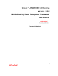
• Define modeling environments for widely-used component models: Cadena's meta-modeling
capabilities can be used to formally capture the definition of widely used component models such as
the CORBA Component Model (CCM), Enterprise Java Beans (EJB), and nesC (a component model
for sensor networks built on TinyOS). Meta-models can include attributes that represent settings and
parameters for underlying middleware frameworks on which systems will be deployed.
• Define domain-specific component models: Cadena meta-modeling can also be applied to specify new
component models, including domain-specific component models that are tailored to the characteristics
of a particular domain or underlying middleware capabilities.
• Flexibly combine and extend multiple component models in a single system: Cadena meta-models
(called styles) can be directly manipulated using style operations. This provides a variety of powerful
and useful capabilities to system architects.
• Styles can be extended through inheritance. This enables reuse of meta-model definitions, and
facilities refinement of platform definitions (multi-step platform-independent to platform-specific
model refinement).
• Multiple styles can be combined within the same architecture model environment to support
development of systems of systems that incorporate multiple component models.
• Define end-to-end model-driven development environments: Cadena's base set of capabilities can
be extended using plug-in mechanisms based on the Eclipse plug-in architecture. This enables
infrastructure developers to build end-to-end model-driven development environments that include
facilities for editing component implementations, model-level configuration of middleware capabilities,
code generation, simulation, verification, and creating system builds. Plug-ins can also be developed
to link other development tools including tools for requirements capture and down-stream class-level
modeling tools such as Rational Rose or Modeler or iLogix Rhapsody.
Figure 1.1. The Cadena meta-modeling language
Component Based Development
TODO: Give an overview of component based development here. Talk about how components provide
interfaces which are connected by connectors.
1
Overview
Eclipse Overview
TODO: A short description of Eclipse here
Cadena Installation
This manual assumes that you have Cadena installed properly. For more information on installing Cadena
please read the Cadena 2.0: Install Guide.
2
Chapter 2. A Cadena Project
Overview
A project serves as the basic organizational unit of Cadena. Related artifacts can be stored and grouped
within projects. Artifacts of one project may be made visible to another project by creating a project
dependency between the two projects.
The New Project Wizard
Before any Cadena artifacts can be created, a project must be created to contain them. To create a new
project:
• Select "File # New # Project..." from the main menu.
• The new project dialog should appear. From the tree on the left, select "Cadena # Cadena Project" and
then click the "Next" button.
• The Cadena Project page of the wizard should appear. To continue, a valid project name must be entered.
Once a valid project name has been entered, the "Finish" button may be clicked to create the project.
The new project should now show up within the resource navigator view.
Configuring a Project
Paths
Within a project, paths are used to specify what directories artifacts must be placed in to be visible to other
artifacts. Separate directory lists are maintained for each type of Cadena artifact. When a new project is
created, a default set of specification paths are configured: specification/style, specification/module, and
specification/scenario for styles, modules and scenarios respectively.
To view the specification paths for a project:
• Right-click on the project within the resource navigator view and select "Properties" from the main
menu.
• The project properties dialog should appear. From the tree on the left, select "Cadena Specification
Paths". The specification paths page should appear to the right.
There is a separate tab for each type of Cadena artifact. The specification path of each type of artifact can
be set through these tabs. The list within each tab shows the currently defined paths.
A path can be removed by selecting it from the list and clicking the "Remove" button. Clicking the "Add
Folder..." button will cause a folder selection dialog to be displayed which allows additional paths to be
added to the list.
If a path specified in Cadena configuration cannot be resolved it will still be listed. When this happens it
will be denoted in that dialog with a RED X. You can remove this path from the list by selecting it and
pressing the "Remove" button. You can also remove all bad (or errorneous) paths from the list using the
Cleanup button.
3
A Cadena Project
Project Dependencies
By default, artifacts within one project are not visible to artifacts within other projects. However, these
artifacts can be made visible by creating a project reference. Once a reference to a project is established,
artifacts that are contained within the referenced project will be visible within the project that created the
reference. 1.
To view a project's references:
• Right-click on the project within the resource navigator view and select "Properties" from the main
menu.
• The project properties dialog should appear. From the tree on the left, select "Project References". The
references page should appear to the right.
References to projects are indicated by the checkboxes located next to the name of each project. A reference
can be added or removed by clicking on the checkbox of a project.
1
For the artifacts of one project to be visible to the artifacts of a referencing project, the artifacts must be located on the referenced project's
specification paths.
4
Chapter 3. Style Tier
Inside a Cadena style, the shapes (or structures) of the architectural elements are described (i.e., the
vocabulary of a platform is introduced). Another way to look at this is that the style-tier is the factory for
the constituent parts of an architecture.
The New Style Wizard
To create a new style:
• Use the navigator view to browse to a folder within a Cadena project where the style will be placed.
The folder that is chosen should be a part of the style path for the project.
• Right click on the chosen folder and select " New # Other " from the pop-up menu.
• The new resource dialog should appear. From the tree on the left, select " Cadena # Cadena Style " and
then click the "Next" button.
• The Cadena Style wizard page of the wizard should appear. To continue, a valid style name must be
entered. Once a valid style name has been selected, click the "Finish" button to create the style.
If the style is succesfully created, a style editor for the new style will be opened.
The Style Editor
The style editor is used to view and modify Cadena styles. The editor has two tabs: the Overview tab, and
the Table tab. The Overview tab is used to view and modify general aspects of the style while the Table tab
provides a table based view for viewing and modifying the individual elements that comprise the model.
Providing the Visual Style
The Cadena Style editor allows the user to configure visual properties of the editor so that the user can
have a richer experience. The customizations are rudimentary at this time but should be sufficient for most
users. If more customizations are necessary, a plugin should be created for the style.
To make changes to the visual style a user must create a file with a name that follows this pattern:
<styleFileName>.visuals (where <styleFileName> is the name of the style file before the .style). This will
be a simple text file that uses the Java properties format. Each property provides the Style editor with
configurations that can enhance the look-n-feel of the editor to match user expectations. Therefore, the
property names and values are important.
The first configurable item is the icon used for interface kinds. The naming scheme that is used is
based upon the name of the kind followed by .icon. For example, if we have an interface kind named
testInterfaceKind, we can set the icon that is used to denote it by setting testInterfaceKind.icon=test.gif.
We suggest you use an icon that whose size is 16x16 (pixels).
The second configurable item is the color used for component kinds (as well as meta-kinds).
The naming scheme that is used is based upon the name of the kind followed by .color. For
example, if we have a component kind named testComponent, we can set the color that is used to
testComponent.color=red. The values that can be used must be in the set of Eclipse Draw2d color constants
(org.eclipse.draw2d.ColorConstants) or a proper HEX value (e.g., #FF0000 is red and #CCEEFF is bluish).
This set of colors is listed in Table 3.1, “Visual Style Color Values”.
5
Style Tier
Table 3.1. Visual Style Color Values
blue
darkBlue
lightBlue
gray
darkGray
lightGray
green
darkGreen
lightGreen
black
white
cyan
orange
red
yellow
Kinds
The starting point of a Cadena architectural specification is the definition of kinds (sometimes referred to
as platform types or architectural types) in a Cadena style to describe a meta-model of the architectural
elements that can be used in the construction of a system. The kinds available in Cadena fall into the
three categories fundamental to component-based systems: components, interfaces, and connectors. Each
kind definition (e.g., a component kind) in a Cadena style defines a language of types (e.g., a language of
component types) that can be used in the construction of a system.
For the construction of a kind for an architectural element, Cadena offers the concept of meta-kinds,
intuitively a toolkit to build shapes, or structures, which form the vocabulary for the types. Unlike concrete
kinds, meta-kinds are allowed to extend from one another. For one meta-kind to inherit from another means
that all of the features that are defined in the parent meta-kind are also present in the child meta-kind.
Three root meta-kinds are present in the core style: mComponent, mInterface, and mConnector. All kinds
and meta-kinds must inherit either directly or indirectly from the appropriate root meta-kind.
To create a kind or meta-kind:
• Change to the Table tab of the style editor.
• Right click within the main table to bring up the pop-up menu. To create a kind or meta-kind, select
one of the options from the "New * Kind" or "New * Meta-Kind" submenus, respectively. The "New
Kind" wizard should appear.
• A unique name that no other kind or meta-kind uses must be chosen. A parent meta-kind—either one
of the core meta-kinds, or another user- created meta-kind—must also be selected. Click the "Finish"
button to create the new kind or meta-kind.
If the kind or meta-kind was successfully created, it should now show up in the table. Double-clicking on
it will bring up the properties view allowing some of the item's properties to be manipulated.
Meta-kinds have the following properties that may be changed:
Table 3.2. Meta-kind properties
Name
Description
name
The name of the component meta-kind. It should be unique among kinds and
meta-kinds.
exposed
If set to true, it can be used as a parent meta-kind within styles that extend
from the containing style. See below for more information about meta-kind
inheritance.
parent
The parent of the meta-kind. See below for more information about metakind inheritance.
6
Style Tier
Kinds have the following properties that may be changed:
Table 3.3. Kind properties
Name
Description
name
The name of the component meta-kind. It should be unique among kinds and
meta-kinds.
ComponentMetaKind
/ InterfaceMetaKind /
ConnectorMetaKind
The meta-kind that the kind finalizes.
Interface Kinds
The first kind category is the interface-kinds category. Interface-kinds categorize interaction points of
platform components and check compatibility between component and connector.
Component Kinds
The second kind category is the component-kinds category. Component-kinds describe the software-unit
primitives of a platform. Each component kind may be instantiated as zero or more component types within
the module tier. Each of those component types may be further instantiated as component instances within
the scenario tier.
Component meta-kinds expose possible interaction-points through port-options. Port-options are used to
declare and constrain the kinds of ports that a component type may contain. Port-options are also used to
constrain the connections that are allowed to ports of a component instance. Port-options are declared in
component meta-kinds and then finalized within component kinds. To add a port-option to a component
meta-kind:
• Change to the Table tab of the style editor.
• Right click on the component meta-kind to bring up the pop-up menu. Select "Add Port-Option" from
the menu.
• A new port-option should now be present as a child to the component meta-kind and it should
automatically be selected. To complete the port option's specification, a few properties must be set. If
the properties view is not already visible, double-click on the port-option to make the properties-view
visible.
7
Style Tier
Table 3.4. Port-spec properties
Name
Description
name
A keyword to uniquely identify the kind of a port.
interfaceMetaKind
The interface meta-kind of the port-spec. When a component kind is created,
an interface kind needs to be specified for each port-spec that is present in
the component kind's meta-kind. The interface kind must inherit from the
interface meta-kind that is specified here.
parity
The parity of the port-spec. In order to connect the port of a component
instance to a connector, the parity of the port's port-spec must match the
parity of the connector's role. The parity can be set to either USES or
PROVIDES.
minimumMultiplicity
The minimum multiplicity of the port-spec. This property restricts the
minimum number of ports that a component type may contain of this portspec.
maximumMultiplicity
The maximum multiplicity of the port-spec. This property restricts the
maximum number of ports that a component type may contain of this portspec.
minimumMultiplexity
The minimum multiplexity of the port-spec. This property restricts the
minimum number of connections that may be made to a port of this kind
within a component instance.
maximumMultiplexity
The maximum multiplexity of the port-spec. This property restricts the
maximum number of connections that may be made to a port of this kind
within a component instance.
Within a concrete component kind, a port-option binding must be present for each of the port-options
present in the component kind's meta-kind. For each of these bindings, a concrete interface kind must
be chosen. The concrete interface kind must inherit from the interface meta-kind that was chosen for the
port-option.
When a component kind is created, bindings are automatically created for all of the port-specs. However,
if a component kind already exists and a port-spec is added to or removed from its meta-kind, the bindings
must manually be fixed by right-clicking on the component-kind and selecting "Fix Bindings" from the
pop-up menu.
Port-spec bindings have the following properties:
Table 3.5. Port-spec binding properties
Name
Description
interfaceKind
The interface kind that the port-spec is bound to. Only interface kinds that
inherit from the port-spec's chosen interface meta-kind may be used.
Connector Kinds
Connector-kinds are the final category of kinds. Connectors model the services provided by the
platform. The chosen platform may include a variety of middleware services, supporting inter-component
communication, distribution, persistence, and state-replication among others. These services are modeled
through connectors, where a connector represents a distinct service of the platform. Since connectors
represent services provided by the platform, there is no need to create connector types within the module
tier. Instead, connector kinds are instantiated directly as connections within the scenario tier.
8
Style Tier
Each connector definition consists of a number of role declarations, much like the port-options
in component-kinds. Single-role connectors abstract services such as timeout-generators; multi-role
connectors model inter-component communication-services. When a connector kind is instantiated as
a connection within the scenario tier, each of the connection's roles must be connected to a port of a
component instance.
Roles are created in the same way that port-options are created, by right-clicking on a connector meta-kind
and selecting "Add Role" from the pop-up menu. The role's properties can be modified by double clicking
on the role to display the properties view. A role has the following properties:
Table 3.6. Role properties
Name
Description
name
A keyword to uniquely identify the name of a role.
interfaceMetaKind
The interface meta-kind constrains the kinds, and possibly the types, of
interfaces that a role may be connected to. The value must be either an
interface meta-kind or an interface-type-variable.
If an interface meta-kind is used, the role must be bound to a concrete
interface kind when the connector meta-kind is finalized as a connector kind.
When a connector is instantiated as a connection in the scenario tier, the
role must be connected to a port of the same interface kind. This is useful
for single-role connectors where the compatibility of multiple roles does not
need to be enforced.
If an interface-type-variable is used instead, the role not only needs to be
connected to a port of the same interface kind as the type variable, but it must
also be connected to a port of the same interface type as all of the other roles
which share the interface-type-variable.
parity
The parity of the role constrains the kinds of ports that the role may be
connected to. Roles may only be connected to ports where the parity of the
role matches.
Connector meta-kinds may also contain interface-type-variables. Interface type-variables are used to insure
that a group of roles within a connection are all connected to ports of the same type. Interface type-variables
have the following properties:
Table 3.7. Interface type variable properties
Name
Description
name
A unique identifer of the interface-type-variable. The name must not be
reused by other interface-type-variables.
interfaceMetaKind
The interface meta-kind of the interface-type-variable. It is used to constrain
the interface kind of an interface type variable binding.
When a connector meta-kind is finalized as a connector kind, a binding must exist for each of the roles
and interface-type-variables contained in the parent meta kind. A binding has the following properties:
9
Style Tier
Table 3.8. Role/Interface type-variable binding properties
Name
Description
interfaceKind
The interface kind that this binding is bound to. (Note: this property is not
present if the binding is for a role and the role specified is an interface-typevariable as it's interface constraint). Only interface kinds that inherit from the
role's chosen interface meta-kind may be used.
Attributes
While kinds and kind features are useful for creating the functional aspects of a model, it is often useful
to attach non-functional data in the form of non-stateful attributes. Attributes are useful in configuring
the underlying middleware and service infrastructure of a system. The attribute values can then be
used for many things including schedulability analysis, code generation, configuration management, and
deployment configuration generation.
Attribute specifications may be attached to any meta-kinds. To add an attribute specification, right-click
on a meta-kind and select "Add Property Type". The new attribute specification should show up as a child
of the meta-kind. An attribute specification has the following properties:
Table 3.9. Attribute specification properties
Name
Description
name
The unique identifier of the attribute. Attribute values are named according
to their specification's name
kind
The binding time of the attribute. This binding time determines at what tier in
the model a value can be assigned to the attribute.
theType
The type of the attribute. The following attribute types are supported:
string, integer, boolean, enum, struct, and collection. The attribute types are
described in more detail below.
defaultValue
The default value of the attribute. This is an optional property. If no value is
specified for an attribute by the user, the value of the attribute is then equal to
the default value.
Basic Property Types
The following basic property types are supported:
10
Style Tier
Table 3.10. Basic Property Types
Name
Description
string
A sequence of characters.
integer
A numerical integer.
boolean
An enumerated domain corresponding to the usual notion of the
mathematical Boolean field. The two legal literals in this enumerated type
are true and false.
enum
A user defined enumerated value. To use this property, one or more
enum members need to be added. To add a member, expand the attribute
specification so that the "<enum-type>" child is visible. Right click on the
child and select "Add Enum Member" from the menu. The new member
should show up as a child of the "<enum-type>" child. Double-click on the
new enum member and set its name.
struct
A struct is a composite type that allows one more nested named child
properties (called struct members). To add a child struct member, expand
the attribute specification so that the "<struct-type>" child is visible. Right
click on the child and select "Add Struct Member" from the menu. The new
member should show up as a child of the "<struct-type>" child. Double-click
on the new struct member to set its name and type.
collection
A collection allows multiple values to be specified for an attribute value.
A collection type must specify the type of the elements it may contain,
the minimum and maximum number of elements it may contain, and the
collection type. The collection type may be either "BAG", "SEQUENCE", or
"SET". To set these properties, expand the attribute specification so that the
"<collection-type>" child is visible and double click on it.
User Defined Property Types
Reusable user defined types, or typedefs, may be created as well. Type defs may be used by multiple
attribute specifications. This feature can be especially useful when a complex struct needs to be reused.
To create a typedef, change to the table and right-click anywhere within the main table. Select "New
Type Def" from the pop-up menu. Double click on the typedef to change it's properties. A typedef has
the following properties:
Table 3.11. Typedef properties
Name
Description
name
The unique identifier of the typedef.
type
The type of the typedef. The type can be any one of the basic types described
above, or the type can be another typedef.
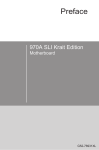
Property Values
Property values may be attached at several points along the Cadena model hierarchy. Properties remain
open along the hierarchy until a property value is attached. At the point that a value is specified for the
property, the property becomes finalized. Once a property is finalized, values can no longer be specified for
the property at a lower point in the hierarchy (meaning that values may not be overridden). See Figure 3.1,
“Property Value Hierarchy” for a diagram of the property value hierarchy.
11
Style Tier
Figure 3.1. Property Value Hierarchy
Inheritance
Cadena allows for structural inheritance in two different ways. The first way is meta-kind inheritance.
When one meta-kind inherits from another, all of the features (port-options, roles, & interface-typevariables) of the the parent meta-kind are present in the child meta-kind. It is also possible to refine, or
specialize features from the parent meta-kind within the child meta-kind. For instance, a child connector
meta-kind may refine an interface-type-variable such that it requires a more specialized interface metakind than was required by the parent connector meta-kind.
In the editor, these inherited features are shown with gray text to indicate that they are not declared within
the child meta-kind but at a higher level in the meta-kind's inheritance hierarchy. The feature can be
specialized by double clicking on it to display the properties view and then setting a value to one of the
properties. Once a feature has been specialized, it will be shown with green text.
The second form of structural inheritance Cadena allows is inheritance of styles. For one style to inherit
from another means that the contents of the parent style are also present in the child-style. Meta-kinds are
allowed to inherit from either meta-kinds declared within the same style, or meta-kinds that are declared
in parent styles. Combined, these two forms of inheritance allow not only for the meta-kinds of a single
platform to specialize each other, but meta-kinds of a platform to specialize meta-kinds of a parent platform
to create a specialized platform.
Furthermore, multiple inheritance of styles allows multiple unrelated styles to be bridged together as
a hybrid style. This hybrid style can then contain component kinds that act as translators between the
component kinds of the parent styles, thus allowing scenarios to be created containing interconnected
components from multiple unrelated platforms.
To add or remove a parent style:
• Change to the Overview tab of the style editor.
• To remove a parent style, select a style from the parent style list within the "Parent Styles" section and
click the "Remove..." button.
• To add a parent style, click on the "Add..." button within the "Parent Styles" section. A dialog should
appear which allows for the selection of the parent style.
12
Chapter 4. Module Tier
Once an architecture or platform has been described in a style (see Chapter 3, Style Tier ), a module
using that style can be created. Inside a module users can create component types and interface types
corresponding to the component kinds and interface kinds described within the style.
The New Module Wizard
To create a new module:
• Use the navigator view to browse to a folder within a Cadena project where the module will be placed.
The folder that is chosen should be a part of the module path for the project. The standard location for
this is in the specification/module folder.
• Right click on the chosen folder and select " New # Other " from the pop-up menu.
• The new resource dialog should appear. From the tree on the left, select " Cadena # Cadena Module "
and then click the "Next" button.
• The Cadena Module wizard page should appear. To continue, a valid module name must be entered.
The desired style of the module must also be selected. Once a valid module name and style have been
selected, the "Finish" button must be clicked to create the module.
If the module is succesfully created, a module editor for the new module will be opened.
The Module Editor
The module editor is used to view and modify Cadena modules. The editor has two tabs: the Overview tab,
and the Table tab. The Overview tab is used to view and modify general aspects of the module while the
Table tab provides a table based view for viewing and modifying the individual elements that comprise
the model.
Providing the Visual Style
The Cadena Module editor allows the user to configure visual properties of the editor so that the user can
have a richer experience. The customizations are rudimentary at this time but should be sufficient for most
users. If more customizations are necessary, a plugin should be created for the style.
To make changes to the visual style a user must create a file with a name that follows this pattern:
<moduleFileName>.visuals (where <moduleFileName> is the name of the style file before the .module).
This will be a simple text file that uses the Java properties format. Each property provides the Module editor
with configurations that can enhance the look-n-feel of the editor to match user expectations. Therefore,
the property names and values are important.
The first configurable item is the icon used for interface types. The naming scheme that is used is
based upon the name of the type followed by .icon. For example, if we have an interface type named
testInterfaceType, we can set the icon that is used to denote it by setting testInterfaceType.icon=test.gif.
We suggest you use an icon that whose size is 16x16 (pixels).
The second configurable item is the color used for component types. The naming scheme that is used is
based upon the name of the type followed by .color. For example, if we have a component kind named
testComponentType, we can set the color that is used to testComponentType.color=red. The values that
13
Module Tier
can be used must be in the set of Eclipse Draw2d color constants (org.eclipse.draw2d.ColorConstants) or
a proper HEX value (e.g., #FF0000 is red and #CCEEFF is bluish). This set of colors is listed in Table 4.1,
“Visual Style Color Values”.
Table 4.1. Visual Style Color Values
blue
darkBlue
lightBlue
gray
darkGray
lightGray
green
darkGreen
lightGreen
black
white
cyan
orange
red
yellow
The third configurable item is the location of the port on the component type. This is specified
using the component type name and the port name. For example, if we have a port named myPort
on a component type named myComponent you could specify the location using a property like
myComponent.myPort.side=top. The possible values are top, bottom, left, and right.
The fourth configurable item is the icon used for the port on the component. This is specified
using the component type name and port name. For example, if we have a port named myPort
and a component type named myComponent you could specify the icon using a property like
myComponent.myPort.icon=test.gif. We suggest you use an icon whose size is 16x16 (pixels).
You should note that inheritance of these properties will occur. So if you define a property in the style-tier,
it will be inherited at the module tier. For example, if you set the color of a kind at the style-tier, you will
get this color at the module tier if you don't override it with a more specific color.
Types
TODO: give some text describe the roles of types in a cadena model
To create a new type:
• Change to the Table tab of the module editor.
• Right click within either the "Component Types" or the "Interface Types" table to bring up the pop-up
menu. Either the "Add Interface Type" or "Add Component Type" submenu should appear as an option,
depending on which table was right clicked in. The submenu contains separate menu options for each
of the interface kinds or component kinds that are declared in the style. Select one of the options. The
new type wizard should appear.
• A unique name that no other type uses must be chosen. Once a name is chosen, click the "Finish" button
to create the new type.
If the type was succesfully created, it will now show up in the table. Double-clicking on it will bring up
the properties view allowing some of item's properties to be manipulated.
All types have the following properties that may be changed:
Table 4.2. Type properties
Name
Description
name
The name of the type. It should not be reused by any other type.
14
Module Tier
Interface Types
Each port of a component designates one interface type as the shape to which it conforms. A connector kind
may use the interface types of ports to insure that only ports of compatible interface types are connected
together by a connector.
If an interface type is selected, all of the ports of that interface type will be selected in the component
types table.
Component Types
Each component kind created within the module's style may be instantiated as zero or more component
types within the module. Each of these component types may be further instantiated as zero or more
component instances within the scenario tier.
Component types have the following additional properties:
Table 4.3. Component Type properties
Name
Description
parent
The parent component type of the component type. A child component type
of a parent component type inherits all of the ports of it's parent component
type.
abstract
If a component type is abstract, it can not be instantiated as a component
instance. The value is either true or false.
Component types may contain ports. Ports are used to expose concrete interaction-points. Each port must
be associated with a port-option declared by the style. Each port must also be associated with an interfacetype. The combination of the port-option and interface type of the port helps determine its compatibility
with roles of a connector within the scenario tier. To add a port to a component type:
• Change to the Table tab of the module editor.
• Right click on the component type to bring up the pop-up menu. Select the "Add Port" submenu. In the
submenu, there are separate options for each of the port-options that are declared in the style. Select
one and the new port wizard should appear.
• A unique name that no other port in this component type uses must be chosen. An interface-type
belonging to the port-option's kind must also be chosen. Once a name and interface type are chosen,
click the "Finish" button to create the new port. If the new port was successfully created, it should now
show up as a child of the component type.
Component ports have the following properties:
Table 4.4. Component port properties
Name
Description
name
The name of the port. The name should be unique with respect to the other
ports contained within the component type.
interface
The interface type of the component port. The port should belong to the same
interface kind as specified by the port's port-option.
15
Module Tier
Imported Modules
In order for a child component type to extend another parent component type, the parent component type
must be visible. In order for a component port to use an interface type as its type, the interface type must
also be visible. Types declared within a module are automatically visible to all of the other types within
the same module. To make a type declared in one module visible to types declared in another module, the
module where the type is declared must be imported by the other module. To view and modify a module's
import list:
• Change to the Overview tab of the module editor. The "Imported Modules" section of the overview
page shows the list of currently imported modules (by default, this list is empty).
• To add a module to the import list, click the "Add..." button to the right of the list. A dialog will appear
allowing modules to be selected for import. Select the modules for import and click the "OK" button.
The import list should now be updated to show the newly imported modules.
• To remove a module from the import list, select the module from the list and click the "Remove..."
button. The import list should now be updated.
16
Chapter 5. Scenario Tier
Once an architecture or platform has been described in a style (see Chapter 3, Style Tier) and a module
with component types has been created (see Chapter 4, Module Tier), a scenario can be created. Scenarios
contain instances of component types, instances of other scenarios (as nested scenarios), and connectors
which tie the instances together.
The New Scenario Wizard
To create a new scenario:
• Use the navigator view to browse to a folder within a Cadena project where the scenario will be placed.
The folder that is chosen should be a part of the scenario path for the project. The standard location for
this is in the specification/scenario folder.
• Right click on the chosen folder and select " New # Other " from the pop-up menu.
• The new resource dialog should appear. From the tree on the left, select " Cadena # Cadena Scenario
" and then click the "Next" button.
• The Cadena Scenario wizard page of the wizard should appear. To continue, a valid scenario name must
be entered. The desired style of the scenario must also be selected. Once a valid scenario name and style
have been selected, the "Finish" button may be clicked to create the scenario.
If the scenario is succesfully created, a scenario editor for the new scenario will be opened.
The Scenario Editor
The scenario editor is used to view and modify Cadena scenarios. The editor has three tabs: the Overview
tab, the Table tab, and the Graph tab. The Overview tab is used to view and modify general aspects of the
scenario. The Table tab provides a table based view for viewing and modifying the individual elements that
comprise the model. The Graph tab provides a graph based view for viewing and modifying the individual
elements of the model as well.
Providing the Visual Style
The Cadena Scenario editor allows the user to configure visual properties of the editor so that the user can
have a richer experience. The customizations are rudimentary at this time but should be sufficient for most
users. If more customizations are necessary, a plugin should be created for the style.
To make changes to the visual style a user must create a file with a name that follows this pattern:
<scenarioFileName>.visuals (where <scenarioFileName> is the name of the style file before the .scenario).
This will be a simple text file that uses the Java properties format. Each property provides the Scenario
editor with configurations that can enhance the look-n-feel of the editor to match user expectations.
Therefore, the property names and values are important.
The first configurable item is the color used for component instances. The naming scheme that is used is
based upon the name of the instance followed by .color. For example, if we have a component instance
named testComponent, we can set the color that is used to testComponent.color=red. The values that can
be used must be in the set of Eclipse Draw2d color constants (org.eclipse.draw2d.ColorConstants) or a
proper HEX value (e.g., #FF0000 is red and #CCEEFF is bluish). This set of colors is listed in Table 5.1,
“Visual Style Color Values”.
17
Scenario Tier
Table 5.1. Visual Style Color Values
blue
darkBlue
lightBlue
gray
darkGray
lightGray
green
darkGreen
lightGreen
black
white
cyan
orange
red
yellow
The second configurable item is the location of the port on the component instance. This is specified
using the component instance name and the port name. For example, if we have a port named myPort
on a component instance named myComponent you could specify the location using a property like
myComponent.myPort.side=top. The possible values are top, bottom, left, and right.
You should note that inheritance of these properties will occur. So if you define a property in the style- or
module-tier, it will be inherited in the scenario-tier. For example, if you set the color of a kind at the
style-tier, you will get this color at the scenario tier if you don't override it with a more specific color.
Imported Modules
Before any component instances can be created, component types must be made visible to the scenario.
This is done in the same way that modules must be imported by other modules in order to make types
visible to other modules. Modules must be imported by a scenario in order to make the module's types
visible within the scenario. To view and modify a scenario's import list:
• Change to the Overview tab of the scenario editor. The "Imported Modules" section of the overview
page shows the list of currently imported modules (by default, this list is empty).
• To add a module to the import list, click the "Add..." button to the right of the list. A dialog will appear
allowing modules to be selected for import. Select the modules for import and click the "OK" button.
The import list should now be updated to show the newly imported modules.
• To remove a module from the import list, select the module from the list and click the "Remove..."
button. The import list should now be updated.
Component Instances
Once one or more modules containing component types are imported by the scenario, instances of the
component types can be created. To create a new component instance:
• Switch to either the "Table" view, or the "Graph" view.
• If the table view is visible, right-click within the "Instances" table to make the pop-up menu visible.
If the graph view is visible right-click anywhere within the main editor area. The "Add Component
Instance" submenu should be available as an option within the pop-up menu. The submenu contains
separate menu options for each of the component kinds that are declared in the style. Select the desired
component kind. The new component instance wizard should appear.
• A unique name that no other instance uses must be chosen. A component type must also be chosen by
clicking on the "Browse..." button and selecting a component type from the dialog. Once a name and
component type have been chosen, click the "Finish" button to continue.
The new component should show up in both the "Graph" tab, and the "Table" tab. Within the graph view,
the component can be dragged around and dropped in a different location.
18
Scenario Tier
Connections
Once one or more instances have been created, connections may be created to connect the instances
together. Connections may be made a few different ways. The first way to make a connection is described
below:
• Switch to either the "Table" view, or the "Graph" view.
• If the table view is visible, right-click within the "Instances" or "Connections" tables to make the pop-up
menu visible. If the graph view is visible right-click anywhere within the main editor area. The "Add
Connector" submenu should be available as an option within the pop-up menu. The submenu contains
separate menu options for each of the connector kinds that are declared in the style. Select one of the
options. The new connection wizard should appear.
• The main table in the wizard displays each role of the selected connector kind. Each role must be bound
to a type-correct port. To bind a role, select the binding from the table and choose an instance and port
combination from the binding drop down box. Once a type-correct binding has been chosen for each
role, click the "Finish" button to create the connection.
The new connection should show up in both the "Graph" tab, and the "Table" tab. Within the graph view,
the connection can be dragged around and dropped in a different location.
To limit the available options displayed in the binding drop down box, multiple instances or ports may
be selected before opening the wizard. For instance if two separate instances are selected, only ports from
those two instances will be available as options in the bindings drop down. If an instance and a port from
another instance are selected, only ports from the selected instance, and the selected port will be displayed
in the drop down box.
Connections can also be created in the following way:
• Switch to the "Table" view.
• Right click on an instance's port within the "Instances" table to display the pop-up menu. The "New
Connection for Port" submenu should be available as an option within the pop-up menu. The submenu
contains separate menu options for each of the connector kind/role combinations that the port may be
bound to. Select the desired connector kind/role combination. The new connection wizard should be
displayed. The selected role should already be bound to the port that was right clicked on. The remaining
roles need to be bound to ports in the same way as above.
Once a connection has been created, the roles can be bound to different ports two different ways. The
first way is by using the properties view. The role must be selected either in the "Connections" table in
the "Table" view, or by selecting the role in the graphical view (the role is visualized as a line between
the connection and the component/port). Once the role is selected, it's "instanceRole" property may be
changed in the properties view.
The second way is by using the "Graph" view. If role is selected in the "Graph" view, drag points will
displayed on its two end points. The end of the role that is connected to a component's port can be dragged
to another component's port using this drag point. If the new component port can be bound to the role, a
cursor that looks like a "+" will be displayed. If the new component port can not be used, a circle with
a line through it will be displayed.
Tips on Navigating the Scenario Editor
There are many ways to use the Scenario Editor to get the job done. Below you will find a list of tips on
using the Scenario Editor in an efficient manner.
19
Scenario Tier
• When using scenario instances in a scenario the user can use the Ctl key along with double-clicking on
the instance to open up the sub-scenario in a new Scenario Editor.
• When using component instances in a scenario the user can use the Ctl key along with double-clicking
on the instance to open up the component type in a new Module Editor.
• For all instances in a scenario the user can double-click on the instance to open up the Propertiew View
that will show the properties associated with that instance.
• The Graph and Table views are connected in two ways: 1) the underlying model and 2) the graphical
user interface (GUI) state. Specicially, when you are in the Graph view and you have an instance or
connector selected you can switch to the Table view and see that instance of connector selected as well.
20
Chapter 6. Python Scripting
Background
Environment
Cadena includes a slightly modified version of the Jython [http://www.jython.org/] library to provide users
with a Python interpreter to facilitate rapid development and easily shareable units of business logic. This
interpreter allows the developer to exploit the very terse syntax of Python while still maintaining full access
to Java class libraries; the outcome is a powerfully expressive scripting framework.
A short example conveys the concept of using Java objects inside a Python environment:
# usual Python import syntax
from java.util import *
from java.math import BigInteger
# call constructor as usual in Python
list = LinkedList()
list.add(BigInteger.valueOf(1))
list.add(BigInteger.valueOf(2))
list.add(BigInteger.valueOf(3))
# native Python iteration across Java collections
for element in list:
print "%s (%s)" % (element, element.getClass())
Usage
Python scripts are launched by right-clicking inside the Table or Graph tabs of a Cadena editor, then
choosing " Jython # Run Jython Script ." A file selector dialog appears; after choosing the script (a file
ending with the .py extension), it is immediately executed. A short history of recently executed scripts
is maintained inside the Jython menu for easy repetitive launching.
When the interpreter for the script is initialized, the identifier selection is bound to the current set of
Cadena model objects selected/highlighted in the user interface. It is a Java object implementing the JFace
interface ISelection [http://help.eclipse.org/help31/topic/org.eclipse.platform.doc.isv/reference/api/org/
eclipse/jface/viewers/ISelection.html] . Each element (if selection is an IStructuredSelection ) is a
Cadena model object; that is, a CalmObject [http://cadena.projects.cis.ksu.edu/api/edu/ksu/cis/cadena/
core/specification/base/CalmObject.html] .
Thus, the usual idiom for a Python script to find the Java object for each current selection is as follows:
# Eclipse API imports
from org.eclipse.jface.viewers import IStructuredSelection
# Current set of objects selected in user interface is held
21
Python Scripting
# by "selection" container
if isinstance(selection, IStructuredSelection):
for selectedObject in selection.toList():
# do some work on the model element
print selectedObject
Object Model
A Cadena model is exposed to the Python interpreter simply as the underlying Java objects used to represent
the model inside Cadena (listed at http://cadena.projects.cis.ksu.edu/api/index.html ). The Cadena object
model itself is implemented using the Eclipse Modeling Framework [http://www.eclipse.org/emf/] ; as a
consequence, every Cadena model object ( CalmObject ) has extensive metadata available, including its
position in parent/child relationships (via the eContainer and eContents methods, respectively).
In general, a Python script writer will use these Javadoc references to learn what properties (bean-style
get / set pairs) and children are available on each Cadena model element. All methods available on the
public statement of the metamodel's API are callable from Python. For instance, displaying the name of
each component instance in a scenario could be done as follows:
# Core Cadena API imports
from edu.ksu.cis.cadena.specification.scenario import Scenario
from edu.ksu.cis.cadena.specification.scenario import ComponentInstance
# Eclipse API imports
from org.eclipse.jface.viewers import IStructuredSelection
#
# Main procedure; assumes that currently selected element
# is the top-level scenario container
#
if isinstance(selection, IStructuredSelection):
scenario = selection.getFirstElement()
# use the bean-style abbreviation of getComponentInstances()
for c in scenario.componentInstances:
assert isinstance(c, ComponentInstance)
print "Scenario %s contains component %s" % (
scenario.name,
c.name)
If the developer is interested only in running a script across the entire model (let us
suppose a
Scenario
[http://cadena.projects.cis.ksu.edu/api/edu/ksu/cis/cadena/core/specification/
scenario/Scenario.html] ), then it suffices to trace the containment relation from just the first selected
element:
# Eclipse API imports
from org.eclipse.emf.ecore import EObject
from org.eclipse.jface.viewers import IStructuredSelection
22
Python Scripting
# Iterate up through containment relation, eventually finding
# the top top of the model.
def findRoot(elem):
while not elem is None and not elem.eContainer() is None:
elem = elem.eContainer()
return elem
if not selection.isEmpty() and isinstance(selection, IStructuredSelection):
scenario = findRoot(selection.getFirstElement())
Python Enhancements to Object Model
Some common tasks for writers of scripts (for example, "fetch the value of an integer-typed attribute attr
on a ComponentInstance c ") are conceptually simple, but somewhat verbose to accomplish when directly
using the Java API to Cadena's metamodel. The Java code to accomplish this would look like the following:
public long getAttrValue(ComponentInstance c, String attrName)
{
for (PropertyDeclaration pd : c.getAllPropertyDeclarations())
{
if (pd.getName().equals("attr"))
{
DirectProperty value = c.getPropertyValue(pd, false);
if (value != null)
{
return ((IntegerValue) value.getValue())
.getValue();
}
Property defaultValue = pd.getDefaultValue();
if (defaultValue != null)
{
return ((IntegerValue) defaultValue.getValue())
.getValue();
}
return null;
}
}
throw new NoSuchElementException(
"No such property declared on component");
}
This is somewhat disappointing, given that the concept encoded would normally be written in a
specification language as this elegant fragment:
23
Python Scripting
c.attr
To avoid requiring script authors to essentially translate the Java code listing above into Python functions
which then are invoked using the style x = getAttrValue(c, "attr") , the Cadena Python
interpreter has been enhanced to attach "helper" functions at several points in the Cadena metamodel
API. These helper functions are accessed simply by requesting a particular field name on the metamodel
object. For example, the ComponentInstance object is augmented to invoke a helper method very similar
to getAttrValue above whenever some attribute analogous to attr is requested. Thus one can simply
write c.attr in Cadena-Python to fetch the value of a property named "attr" on a component instance.
Table 6.1, “Supplementary Attributes in Python Environment” gives a full listing of all these various
syntax-sugar attributes.
24
Python Scripting
Table 6.1. Supplementary Attributes in Python Environment
Java Type
Additional Attribute
Description
ComponentInstance
any port option name n
If n is the name of a port-option on the component
kind from which the ComponentInstance derives,
then the attribute n yields a map whose keys are
the names of the ports declared inside that port
option, and whose values are PortProxy instances
(detailed below). If no such port-option n exists,
then a NameError is raised.
any property name n
If n is the name of a property declared to exist
on the kind or type from which the component
instance is derived, then the value of that property.
If no such property is declared, then a NameError
is raised.
any port name n
A PortProxy (detailed below) representing the port
named n on the subassembly instance. If no port
named n exists, then a NameError is raised.
any property name n
If n is the name of a property declared to exist on
the subassembly from which the ScenarioInstance
is derived, then the value of that property. If no
such property is declared, then a NameError is
raised.
instance
The instance (either ComponentInstance or
ScenarioInstance) which owns the port.
port
The port as declared inside the component type
from which the instance is instantiated.
connectors
Fetches a java.util.Collection whose elements are
the Connectors hooked onto the instance's port.
any property name n
If n is the name of a property declared on either
the port or the port option from which it is derived,
then the value of that property. If no such property
is declared, then a NameError is raised.
any role name r
If the connector has a role named r, then r
evaluates to the PortBinding for that role;
otherwise a NameError is raised.
any property name p
If p is the name of a property declared on the
connector's kind, then the value of that property. If
no such property is declared, then a NameError is
raised.
instance
The instance (either ComponentInstance or
ScenarioInstance to which the connector's role is
attached.
port
The port (itself either located on a
ComponentInstance or a ScenarioInstance) to
which the connector's role is attached.
any property name p
If p is the name of a property declared on the
connector, then the value of that property. If no
such property exists, then a NameError is raised.
ScenarioInstance
PortProxy (not in the
core object model)
Connector
PortBinding
25
Python Scripting
Modifying the Model
Because the Java types which implement the Cadena metamodel are built using the Eclipse Modeling
Framework, the pattern and style of methods used to change features of a model is very predictable: if
an object has some attribute attr , then a method setAttr will exist on its Java class. Modifications
to the model usually consist of nothing more than calling this mutator method with the new value passed
as an argument.
Cadena imposes one extra requirement on changes to a model, though: all changes must be performed
by a dedicated thread. One requests the model-change thread to execute a change by submitting a worker
object into a queue, then optionally blocking until the modification has been finished.
The model-change queue requires that changes executed by the run method of an IModelChangeAction
[http://cadena.projects.cis.ksu.edu/api/edu/ksu/cis/cadena/core/queue/IModelChangeAction.html] object.
The usual practice (in the Java universe) is to use instances of anonymous extensions of the adapter
AbstractModelChangeAction class.
CadenaEclipsePlugin.enqueueModelChangeAction(
new AbstractModelChangeAction() {
public void run() {
element.setAttr(newValue)
}
});
A similar thing can be done in the Python environment:
# Cadena API imports
from edu.ksu.cis.cadena.core.queue import AbstractModelChangeAction
from edu.ksu.cis.cadena.eclipse import CadenaEclipsePlugin
class SomeModelChangeAction(AbstractModelChangeAction):
def __init__(self, element, newValue)
self.__element = element
self.__newValue = newValue
def run(self):
self.__element.setAttr(self.__newValue)
element = .... # fetch object to be modified
action = SomeModelChangeAction(element, newValue)
CadenaEclipsePlugin.enqueueModelChangeAction(action)
Putting it all Together
To this point, various idioms for accomplishing isolated tasks inside a Cadena Python script have been
introduced. This section will present an example stitching all these techniques together, to accomplish a
real task.
26
Python Scripting
The Premise
Suppose that a given Cadena scenario exists which has undergone incremental changes over an extended
time. As component instances have been added and removed, the component integrators have not been
careful always to remove those connectors which have unbound roles. This leaves a scenario which is
probably malformed. Although this sort of misconfiguration will probably already be reported as illegal by
the system type-checker, a script capable of excising the offending (not-fully-attached) connectors could
be useful.
Procedure
To begin, create a new file to hold the Python script:
• Choose " File # New # File " from the menu.
• Create a new file cleanConnectors.py inside the project containing the scenario. In principle, this
script could exist anywhere on the filesystem. It is convenient, however, to include it inside a folder
managed by Eclipse; by doing so, one can share scripts over version control and keep the script in close
proximity to the artifact on which it operates.
In general, complete Cadena script will need to accomplish the following tasks: extract the current selection
from the JFace ISelection wrapper object; (possibly) trace the selection backward to find the root model
element; iterate across the contents of the model; and perform some modifications on the model.
cleanConnectors.py will begin by importing some libraries needed (1) to interrogate the current
JFace selection and (2) to make the Java typenames of various Cadena metamodel elements visible:
# Cadena API imports
from edu.ksu.cis.cadena.core.specification.scenario import Connector
from edu.ksu.cis.cadena.core.queue import AbstractModelChangeAction
from edu.ksu.cis.cadena.eclipse import CadenaEclipsePlugin
# Eclipse API imports
from org.eclipse.jface.viewers import IStructuredSelection
After this, a utility function to find the root container (in the present case, a Scenario ) is added just as
before:
# Iterate up through containment relation, eventually finding
# the top top of the model.
def findRoot(elem):
while not elem is None and not elem.eContainer() is None:
elem = elem.eContainer()
return elem
Because the main task of the script is to repeatedly ask whether a proferred connection is fully attached,
it will prove convenient to define a Python function which returns this verdict:
# Check whether every role on a connector is attached to some port
def isFullyAttached(connection):
27
Python Scripting
# sanity check on parameter
assert isinstance(connection, Connector)
# the metakind lists all the roles on the connector
metakind = connection.kind.connectorMetaKind
# make sure that each role has a corresponding binding
# on the connector instance
for ps in metakind.getAllPortSpecs(True):
found = False
for pb in connection.getPortBindings():
if pb.portSpec != ps:
continue
if pb.instanceRole is None:
continue
if pb.instanceRole.instance is None:
continue
if pb.instanceRole.port is None:
continue
found = True
if not found:
return False
return True
Next, an IModelChangeAction object will be needed to encapsulate the work of removing malformed
connectors from the scenario:
# Implementation of IModelChangeAction used to remove the specified
# connector from the specified scenario
class RemoveConnectorJob(AbstractModelChangeAction):
def __init__(self, scenario, connector):
self.__scenario = scenario
self.__connector = connector
def run(self):
self.__scenario.getConnectors().remove(self.__connector)
Finally, some driver code will iterate across the model and submit model-change jobs for each bad
connector:
#
# Main procedure
#
if not selection.isEmpty() and isinstance(selection, IStructuredSelection):
scenario = findRoot(selection.getFirstElement())
28
Python Scripting
connsToRemove = []
for c in scenario.connectors:
if not isFullyAttached(c):
connsToRemove.append(c)
for c in connsToRemove:
job = RemoveConnectorJob(scenario, c)
CadenaEclipsePlugin.enqueueModelChangeAction(job)
Running
After entering all the Python code listings from the section called “Procedure” into the file
cleanConnectors.py , the script is ready to execute:
• Open the model to be cleaned.
• Switch to the Table or Graph tab of the model's editor.
• Right-click and choose " Jython # Run Jython Script ."
• Browse to and select cleanConnectors.py .
As the script runs (parsing and loading it may take a few moments; please be patient), the model will shrink
as any connectors having roles not attached to some port are progressively removed.
29
Chapter 7. Plug-In to Cadena
Overview
Cadena is built using the Eclipse environment and framework. Because of that, it is very easy to enhance
and extend the features that Cadena currently has. This is done through the use of Eclipse plugins.
This section will try to explain and show how a developer can plug into Cadena using the Eclipse plugin
framework. This section is not complete but should give developers a start.
In addition to this section of the manual, developers should also look into the sample projects that are
available with each Cadena release. For example, we release the source for the OpenCCM/CCM and nesC
platform plugins for Cadena. In those two plugins, developers will find examples of styles, visual styles,
actions, wizards, code generators, and much more.
Create a New Platform
One of the ways that Cadena can be extended is by developing plugins for new platforms. For example,
if a developer wants to deploy his application to a J2EE/EJB platform, a platform plugin would need
to be written to facilitate that. The following section will provide some details on how this could be
accomplished.
This section will walk through creating a platform independent model (PIM) for use with sensor networks.
The details of the language are as follows:
• There is a single component kind which has a single property named location.
• Each component instance will have a location associated with it.
• nesC Code will be generated that uses the location.
• There are three kinds of connectors.
• There are three kinds of interfaces.
• The PIM is very closely related to the nesC model so that it is easily translated to nesC.
With that in mind, we will walk through the following steps:
• Create a style that represents the specifications detail above.
• Create an Eclipse plugin for the platform.
• Add the style to the platform plugin.
• Add a visual style to the platform plugin.
• Prototype the code generation with a Jython script.
• Add an action to the platform plugin that will generate nesC code.
Create the Style
The first step in creating a new Cadena platform is to create a style that describes the possibilities. Put
another way, you must describe the kinds of things available in this platform. This is done by describing
what component, connector, and interface kinds that make up this platform. As mentioned before, we are
30
Plug-In to Cadena
trying to stay as close to the nesC model as possible so we will have 1 component kind, 3 connector kinds,
and 3 interface kinds.
As you create the kinds keep in mind that Cadena expects each kind to have a meta-kind as a parent.
Therefore, you should create the meta-kinds first and then create the kinds.
The details of how to create a new style are available in Chapter 3, Style Tier. Using that as a guide, create
the following interface kinds listed in Table 7.1, “eNesC Interface Kinds”.
Table 7.1. eNesC Interface Kinds
Name
Parent
MetaKind?
mMyCommandInterface
mInterface
Y
MyCommandInterface
mMyCommandInterface
N
mMyEventInterface
mInterface
Y
MyEventInterface
mMyEventInterface
N
mMyBundleInterface
mInterface
Y
MyBundleInterface
mMyBundleInterface
N
Figure 7.1. eNesC Interface Kinds
Once the interface kinds are created you should move on to create the connector kinds listed in Table 7.2,
“eNesC Connector Kinds”.
Table 7.2. eNesC Connector Kinds
Name
Parent
MetaKind?
mMyCommandConnector
mConnector
Y
MyCommandConnector
mMyCommandConnector
N
mMyEventConnector
mConnector
Y
MyEventConnector
mMyEventConnector
N
mMyBundleConnector
mConnector
Y
MyBundleConnector
mMyBundleConnector
N
When creating the connector kinds, create two role-options. One role-option should be a USES and be
named client while the other role-option should be a PROVIDES and be named server. Use the appropriate
31
Plug-In to Cadena
interface kinds (for the MyEventConnector kind, use the MyEventInterface kind). A graphical view of
these can be seen in Figure 7.2, “eNesC Connector Kinds”. And a view of them in the Cadena Style Editor
can be see in Figure 7.3, “eNesC Connector Kinds in the Cadena Style Editor”.
Figure 7.2. eNesC Connector Kinds
Figure 7.3. eNesC Connector Kinds in the Cadena Style Editor
Once the connector kinds are created you should move on to create the component kind and name it
MyComponent. It will need 6 port options for the 6 types of connections that it can make.
• usesBundle
• providesBundle
• usesEvent
• providesEvent
• usesCommand
• providesCommand
The MyComponent will also have a single property type named location with an integer type.
32
Plug-In to Cadena
Figure 7.4. eNesC Component Kinds in the Cadena Style Editor
The style is now created and should be saved. To save, open the File menu and select Save Cadena Model.
To continue the journey of creating a new platform for use in Cadena move on to the next section, the
section called “Create the Eclipse Plugin Project”.
Create the Eclipse Plugin Project
Anytime you want to create a new Eclipse plugin you will likely follow the same steps. For more detail
on this, please see the Eclipse documentation that is available online (help.eclipse.org) or in Eclipse (Help
| Help Contents).
In short, you will use a New Project Wizard to create a new plugin project where your style, visual style,
and other extensions will be stored. To start the wizard, select the File menu then the New sub-menu and
finally the Project menu item. A new dialog will be shown and you should select Plugin-in Project and
press Next.
Figure 7.5. Menus to create a new project
At this point you should name it and accept the rest of the defaults on this page (unless you
know better already). We suggest naming it similar to our naming convention. The name starts
33
Plug-In to Cadena
with your domain name in reverse (in our case, edu.ksu.cis) and you append cadena.platform
so that it is obviously a plugin for Cadena and that it is a platform. Finally, append a name
for the platform. In this case, we will name our platform sensorNetwork. This results in a
plugin named edu.ksu.cis.cadena.platform.sensorNetwork. Althought it might be something like
com.wallentine.cadena.platform.sensorNetwork or net.tinyos.cadena.platform.sensorNetwork.
Figure 7.6. New Plugin Project: Name It
The next screen allows you to configure some plugin options that describe the plugin to users. Feel free to
accept the defaults or change them as you see fit. We suggest you at least leave the Plug-in ID and Plug-in
Version alone. This can be seen in Figure 7.7, “New Plugin Project: ID It”. After you are satisfied with
your changes, click Next to continue the wizard.
Figure 7.7. New Plugin Project: ID It
34
Plug-In to Cadena
The next screen provides an easy way to create certain types of plugins using project templates. In this
case, we don't want to use any of the templates so you should unselect the checkbox for "Create a plug-in
using one of the templates". This can be seen in Figure 7.8, “New Plugin Project: Complete It”. Once you
unselect click Finish and the new project will be created for you.
Figure 7.8. New Plugin Project: Complete It
The new plugin project is now created and ready for the style, the visual style, and the new generator.
To continue the journey of creating a new platform for use in Cadena move on to the next section, the
section called “Add the Style”.
Add the Style
Once you have created the style and the plugin project you are ready to move the style into the plugin.
This involves changes to the file system as well as changes to the plugin.
First, you will need to create a location in the file system where the style will reside. The Cadena team
typically uses a single directory name specification in the root of the plugin project. There are many ways
to create a new folder in Eclipse so choose one and create the specification folder. Then copy the new
style file from the Cadena project created in the section called “Create the Style” into the newly created
specification folder. An example of this can be seen in Figure 7.9, “The New Style in the New Plugin
Project”.
35
Plug-In to Cadena
Figure 7.9. The New Style in the New Plugin Project
Now that the plugin project contains the style file, you can tell Cadena about this. This means that you will
need to declare an extension to Cadena using the edu.ksu.cis.cadena.core.specifications extension point.
To do this, open the plugin.xml file using the Eclipse Plug-in Manifest Editor. Once opened switch to the
Extensions view and add the extension (use the Add button to bring up the wizard dialog). In the dialog be
sure to un-select the checkbox labeled "Show only extension points from the required plug-ins". You can
then select the specified extension point and press Finish. This will bring you back to the Manifest Editor
and will add this extension to the list of All Extensions.
Now that the extension is added you will need to configure it. In this case, you will need to add a style
node and specify the URI and resource for that node. In this case, enter the relative path to the style file
(e.g., specification/eNesC.style) in the resource text field (or click Browse to locate it on the file system).
Next, you will need to enter a URI that will provide a unique identifier for this style. The Cadena team uses
a naming scheme similar to the one we use for plugin names. First, we use http as the protocol (so each
URI starts with http://). Next, we use the main web site URL, cadena.projects.cis.ksu.edu. Finally, we use
the name of the style file. In this case, the style is named eNesC.style. So your URI might look something
like http://cadena.projects.cis.ksu.edu/eNesC.style or even http://cadena.wallentine.com/eNesC.style. An
example of this completed can be seen in Figure 7.10, “Complete Style Extension point in Eclipse Plugin-in
Manifest Editor”.
36
Plug-In to Cadena
Figure 7.10. Complete Style Extension point in Eclipse Plugin-in Manifest Editor
Once you have added the URI and resource you can save the changes. You have now added your new
style to your new platform plugin. You are now ready to add the visual style which is described in the
section called “Add the Visual Style”.
Testing the Platform Plugin
Now that you have a platform plugin you may want to test to make sure you have done everything correct
up to this point. This is very easy using Eclipse's built-in facilities for debugging Eclipse plug-ins. You
simply need to run it as an Eclipse Application (a.k.a., a runtime workbench).
Once you start up the new Eclipse instance you can create a new Cadena project. In that new project, you
can create a new Module. When creating that module, you should be able to select your newly create style
from the list. If it isn't available, you have a problem that needs to be debugged.
You can now continue the development of this plugin by developing a visual style, prototyping a code
generator, or building a code generator as an Eclipse action.
Add the Visual Style
This section is not yet complete, please continue on to the section called “Prototype the Generator”.
Prototype the Generator
You now have a working platform plugin that uses your new style. One way to start using that style is
to prototype the code generator that we described before. This can be done using the Cadena scripting
functionality (which is described in Chapter 6, Python Scripting).
To do this, you should start up a runtime workbench with your platform plugin. Once it is started you
should create a new Cadena project. Within that project, you should create new Cadena modules and
scenarios. Those modules and scenarios will be used to demonstrate the scripting capabilities. In this case,
we will walk you through creating 1 Cadena module and 1 Cadena scenario.
You first task is creating a Cadena module (for details on this see Chapter 4, Module Tier). In this new
Module you should create 1 Interface Type and 1 Component Type. You should name the Interface Type
MyServices and make it a MyBundleInterface. Further, name the Component Type MyServer. MyServer
should now use and provide this interface by adding ports (useBundle and providesBundle) and naming
37
Plug-In to Cadena
them usesMyServices and providesMyServices. An example of what the Module Editor would look like
(as well as what the Outline view) is shown in Figure 7.11, “eNesC Example Module”.
Figure 7.11. eNesC Example Module
Now that you have created the Module you should create a new Scenario (details on this can be found in
Chapter 5, Scenario Tier). In this Scenario, you should make sure to import the module you just created.
Once that is done, switch to the Graph or Table view and create 2 instances of the MyServer component
type. And to make it slightly more interesting, connect them. You can see an example of this in Figure 7.12,
“eNesC Example Scenario”.
Figure 7.12. eNesC Example Scenario
If you had the Problems view open you should have seen 2 errors show up (as seen in Figure 7.13, “eNesC
Example Scenario - Error Messages”). This is a reminder that you have not set the location property which
is required. To do this, switch to the Properties view and select an instance. This will populate the Properties
view with the properties associated with that instance. You should notice that the location property is unset
(as seen in Figure 7.14, “eNesC Example Scenario - Properties”). To set it, double-click it and then set
a valid value. Do this for each instance and the errors should disappear. This is important for this demo
since we will be using the value of this location to generate code.
38
Plug-In to Cadena
Figure 7.13. eNesC Example Scenario - Error Messages
Figure 7.14. eNesC Example Scenario - Properties
Now that you have created the module and scenario you are prepared to write the prototype script. To do
this, you will need to familiar with Python and the Cadena core API. For this demo, it should be enough
that you copy-n-paste and follow the directions.
To start, create a new File in the scenario sub-directory named generate.py. Make sure to open it in the
Eclipse Text Editor (depending on what plug-ins you have installed and how you have it configured, it
may open up an external application - like emacs, vi, or notepad). Once opened, enter the following code
which prints the names of the instances and the associated location.
# User Interface API imports
from edu.ksu.cis.cadena.eclipse import CadenaEclipsePlugin
from edu.ksu.cis.cadena.core.queue import AbstractModelChangeAction
39
Plug-In to Cadena
# Eclipse API imports
from org.eclipse.emf.ecore import EObject
from org.eclipse.jface.viewers import IStructuredSelection
# Miscellaneous Java library imports
from java.lang import Runnable, Thread
#
# Fetch the root EObject from the JFace current selection
#
def fetchRoot(selection):
if selection is None or selection.isEmpty():
return None
elif not isinstance(selection, IStructuredSelection):
return None
elif isinstance(selection.firstElement, EObject):
root = selection.firstElement
while not root is None and not root.eContainer() is None:
root = root.eContainer()
return root
# Get the location property value from the given instance. It is
# assumed that the name of the property is location and it has
# a type of IntegerValue. Therefore, the return type is Long (java.lang).
def getLocation(instance):
propertyDeclaration = fetchPropertyDeclaration(instance, "location")
if(propertyDeclaration != None):
directProperty = instance.getPropertyValue(propertyDeclaration, 0)
if(directProperty != None):
propertyValue = directProperty.getValue()
if(propertyValue != None):
return propertyValue.getValue()
return None
# Fetch the property declaration from the given instance that has
# the given property name. The type of the returned object will
# a PropertyDeclaration (edu.ksu.cis.cadena.core.specification.property).
def fetchPropertyDeclaration(instance, name):
for propertyDeclaration in instance.getAllPropertyDeclarations():
if name == propertyDeclaration.getName():
return propertyDeclaration
return None
# Main Logic: Walk through the scenario and print the name of the instance
# and what location it should be deployed to.
# first, we need to get the scenario
scenario = fetchRoot(selection)
# next, we will collect up the component and scenario instances
for instance in scenario.allInstances:
location = getLocation(instance)
40
Plug-In to Cadena
print 'Instance: %(name)s, Location: %(location)d' % \
{'name': instance.name, 'location': location}
Once you have entered the text into the new Python script you should save it. Once saved you can use
it from within the Scenario. Switch to the Scenario Editor that has your Scenario open. If you are in the
Table or Graph view, right-click to bring up the context menu. In that menu there is a Jython sub-menu
that has a menu item named Run Jython Script. Select it and use the dialog to select your newly created
Python script. It should run and print the instance names and locations to the console view (see Figure 7.15,
“eNesC Example Scenario - Python Script Results” for an example of what this should look like).
Figure 7.15. eNesC Example Scenario - Python Script Results
You have now created your first Python script that works with the Cadena API. You can continue to
experiment in this way to query, modify, and create model elements. Once you complete your experiments,
you can transition this logic into a part of your platform plugin (so everyone can use your code generation
when they use your platform). For more on that see the section called “Add a new Generator Action”.
Add a new Generator Action
This section is not yet complete, please continue on to the section called “Continue to Develop”.
Continue to Develop
You have now completed the creation of a platform plugin for Cadena. You can now explore the Eclipse
documentation to see how you can extend Eclipse more as well as how to distribute this plugin to others.
41
Glossary
Cadena
An Eclipse-based extensible integrated modeling and development framework for
component-based systems.
TinyOS
An open-source operating system designed for wireless embedded sensor
networks. It features a component-based architecture which enables rapid
innovation and implementation while minimizing code size as required by the
severe memory constraints inherent in sensor networks.
nesC
An extension to the C programming language designed to embody the structuring
concepts and execution model of TinyOS.
Eclipse
An open source community whose projects are focused on building an open
development platform comprised of extensible frameworks, tools and runtimes for
building, deploying and managing software across the lifecycle.
When we refer to Eclipse it is usually as an IDE or platform and not the project
or community.
workspace
An Eclipse term that refers to the central hub for all user data. This is a specific
folder/directory. A good quote from the Eclipse website is "you can think of the
platform workbench as a tool that allows the user to navigate and manipulate the
workspace".
project
An Eclipse term that refers to a specific type of resource in the workspace. To
be more specific, a workspace contains a collection of projects. Projects contain
files and folders.
Module File
A Cadena term that refers to a file that contains a Cadena Module.
Scenario File
A Cadena term that refers to a file that contains a Cadena Scenario.
Scenario
A Cadena term that refers to a collection of instances (component, scenario, and
connector) that define a modeled application.
Module
A Cadena term that refers to the description of the types available in the model
which will be used at the Scenario tier. Modules contain definitions of Types that
are used to define Scenario instances.
Style
A Cadena term that refers to the description of the platform that will be modeled
at the other tiers of Cadena (module and scenario tiers). In other words, the style
helps define a language to use in the Module tier. Styles contain definitions of
Kinds (and Meta-Kinds) that are used to define Module Types.
nesC Interface
A TinyOS/nesC term that refers to a collection of methods (or method signatures)
with a name. In nesC, components (modules and configurations) provide and use
interfaces.
nesC Module
A TinyOS/nesC term that refers to a component that holds logic. This uses and
provides interfaces, commands, and events. It also holds the logic that maps to the
defined interfaces, commands, and events.
nesC Configuration
A TinyOS/nesC term that refers to a component that does not hold logic. A
configuration defines a collection of components (modules and configurations)
42
Glossary
and connectors as well as an optional collection of interfaces, commands, and
events that it uses and provides. This holds no logic.
Nature
An Eclipse term that refers to flags set on Eclipse projects. These flags help
Eclipse behave in a prescribed way. For example, certain actions, features, and
builders are only available in projects with certain natures. For example, the
Cadena Specification Path can only be defined in a project with a Cadena nature.
Specification Path
A Cadena term that refers to the path Cadena uses to find the model specifications
available in a project. This includes three distinct paths for styles, modules, and
scenarios.
Interface Type
...
Component Type
...
Component Instance
...
Scenario Instance
...
TinyOS Module
A Cadena/nesC term that refers to a Cadena Module that is set to use the nesC
style.
TinyOS Scenario
A Cadena/nesC term that refers to a Cadena Scenario that is set to use the nesC
style.
Architectural
Language (ADL)
Definition
...
Product-Line Development
...
Software Product Lines (SPL)
...
Middleware
...
Type
...
Service
...
Meta Model
...
Component
...
Interface
...
Connector
...
Meta Kind
...
Kind
...
Platform
...
Port Option
...
Role
...
Interface Kind
...
43
Glossary
Component Kind
...
Connector Kind
...
Instance
...
Level
...
Layer
...
Assembly
...
44
Bibliography
[Eclipse:URL] Eclipse . “{Eclipse} Website”. 2001.
[nesC:URL] “nesC Web Site”.
[TinyOS:URL] “TinyOS Web Site”.
[Cadena:URL] “{\sc Cadena} Web Site”.
45