1
Probing
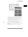
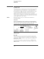
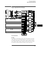
Oscilloscope probes
Oscilloscope probes
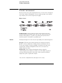
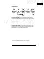
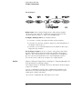
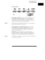
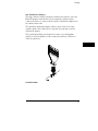
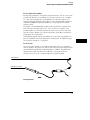
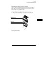
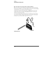
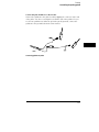
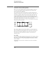
The two oscilloscope probes supplied with the logic analyzer are HP 10430A
Miniature Passive Probes. These small, lightweight probes allow
measurements that were previously very difficult in densely populated
circuits.
For complete information on the operation, maintenance, and adjustments of
the miniature passive probes, be sure to read the operating note that is
packaged with the probes.
Probe Inputs
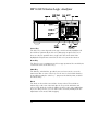
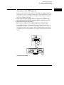
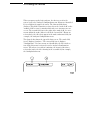
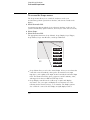
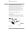
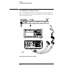
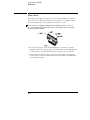
Probe inputs are located on the front panel to the right of the line switch.
Input 1 is on the left. The probes may be connected directly to the BNC
input connectors. The signal is dc-coupled to the oscilloscope.
BNC cables can be connected directly to the BNC connectors. A BNC-to
BNC cable is not provided with the instrument, but you can order it
separately.
Maximum Probe Input Voltage
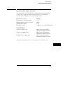
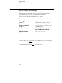
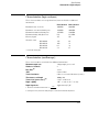
The maximum input voltage of each logic analyzer probe is ±40 volts peak.
The maximum input voltage of the oscilloscope is ±250 volts dc at 1MΩ
setting and ±5 volts rms at 50Ω setting.
Calibration Outputs
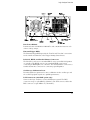
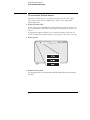
There are two calibration output BNCs located on the rear panel. One is the
dc calibration signal source and the other is the ac calibration signal source.
Both of these signals are used during calibration of the oscilloscope. The dc
calibration signal can also be used for probe compensation adjustment (see
your operating note).
7-11