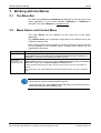
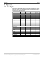
1
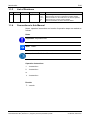
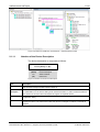
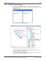
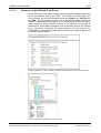
Operating Instruction Manual netDevice and netProject FDT Container Device Catalog Network View Hilscher Gesellschaft für Systemautomation mbH www.hilscher.com DOC040401OI11EN | Revision 11 | English | 2013-09 | Released | Public Table of Contents 2/44 Table of Contents 1 INTRODUCTION.........................................................................................................4 1.1 About this Manual .......................................................................................................4 1.1.1 1.1.2 1.1.3 1.1.4 1.2 Legal Notes.................................................................................................................6 1.2.1 1.2.2 1.2.3 1.2.4 1.2.5 1.2.6 2 netDevice....................................................................................................................9 2.1.1 2.1.2 2.2 netDevice - Graphical Network View..................................................................10 netDevice - Device Catalog................................................................................12 netProject - Network .................................................................................................15 WORKING WITH THE MENUS.................................................................................16 3.1 The Menu Bar ...........................................................................................................16 3.2 Menu Device and Context Menu ..............................................................................16 3.3 Online Functions via the Context Menu ....................................................................19 3.3.1 3.3.2 3.3.3 3.3.4 3.3.5 3.3.6 3.3.7 3.4 Debug Mode .......................................................................................................19 Cut/Copy/Paste ..................................................................................................20 Network Scan .....................................................................................................20 Additional Functions ...........................................................................................21 Additional Functions > Service > Start /Stop Communication ...........................21 Delete .................................................................................................................22 Change Symbolic Name.....................................................................................22 Menu Network...........................................................................................................23 3.4.1 3.4.2 4 Copyright ..............................................................................................................6 Important Notes ....................................................................................................6 Exclusion of Liability .............................................................................................7 Warranty ...............................................................................................................7 Export Regulations ...............................................................................................8 Registered Trademarks........................................................................................8 NETDEVICE AND NETPROJECT ..............................................................................9 2.1 3 Overwiew..............................................................................................................4 Online Help...........................................................................................................4 List of Revisions ...................................................................................................5 Conventions in this Manual ..................................................................................5 netDevice Network Toolbar ................................................................................24 netDevice Debug Toolbar...................................................................................24 WORKING WITH NETDEVICE AND NETPROJECT................................................25 4.1 Getting Started - Configuration Steps.......................................................................25 4.2 The Device Catalog ..................................................................................................27 4.2.1 4.2.2 4.2.3 4.3 Load Device Catalog ..........................................................................................27 Reload Device Catalog.......................................................................................27 Devices of other Vendors ...................................................................................28 Installing Slave DTM or adding Device Description ..................................................29 netDevice and netProject | FDT Container DOC040401OI11EN | Revision 11 | English | 2013-09 | Released | Public © Hilscher, 2004-2013 Table of Contents 4.4 PROFINET IO Device Instance ................................................................................30 4.5 Insert Device in Project.............................................................................................31 4.6 Cutting, copying, pasting Slave Devices...................................................................32 4.6.1 Delete Device from Project .......................................................................................33 4.8 Working with Buslines...............................................................................................34 Description of the Buslines.................................................................................34 Add / Remove Busline........................................................................................35 Arrange Elements in the Graphical Network View .............................................36 Multiselection......................................................................................................37 CONFIGURATION ....................................................................................................38 5.1 Online/Offline Configuration......................................................................................38 5.2 Connect/disconnect Device ......................................................................................39 5.2.1 5.2.2 6 Enlarging Project Configuration..........................................................................32 4.7 4.8.1 4.8.2 4.8.3 4.8.4 5 3/44 Download to Device............................................................................................40 Upload from Device ............................................................................................40 APPENDIX ................................................................................................................41 6.1 User Rights ...............................................................................................................41 6.2 List of Figures ...........................................................................................................42 6.3 List of Tables ............................................................................................................42 6.4 Glossary....................................................................................................................43 6.5 Contacts....................................................................................................................44 netDevice and netProject | FDT Container DOC040401OI11EN | Revision 11 | English | 2013-09 | Released | Public © Hilscher, 2004-2013 Introduction 1 4/44 Introduction 1.1 About this Manual netDevice is a FDT Container for the configuration of field devices of different manufacturers. 1.1.1 Overwiew The table below gives an overview of the descriptions provided in this manual: Chapter Section Manual Page netDevice and netProject netDevice 9 netProject - Network 15 Working with the Menus The Menu Bar 16 Menu Device and Context Menu 16 Menu Network 23 Getting Started - Configuration Steps 25 The Device Catalog 27 Installing Slave DTM or adding Device Description 29 Insert Device in Project 31 Cutting, copying, pasting Slave Devices 32 Delete Device from Project 33 Working with Buslines 34 Online/Offline Configuration 38 Connect/disconnect Device 39 Working with netDevice and netProject Configuration Table 1: Overview 1.1.2 Online Help netDevice contains an integrated online help facility. To open the online help, select Help > Content and Index or press the F1 key. netDevice and netProject | FDT Container DOC040401OI11EN | Revision 11 | English | 2013-09 | Released | Public © Hilscher, 2004-2013 Introduction 1.1.3 5/44 List of Revisions Index Date Version Component Chapter Revision 11 1.1203.x.x AxSyconu.ocx 1.2.6, 2.1.2.1, 2.1.2.2, 4.2.3, 4.4 1.1.4 13-09-06 Section Registered Trademarks updated. Section Search Function in the Device Catalog added. Section Notations to the DTM and to the Device updated, Section Devices of other Vendors added. Section PROFINET IO Device Instance added. Conventions in this Manual Notes, operation instructions and results of operation steps are marked as follows: Notes Important: <important note> Note: <note> <note, where to find further information> Operation Instructions 1. <instruction> 2. <instruction> or <instruction> Results <result> netDevice and netProject | FDT Container DOC040401OI11EN | Revision 11 | English | 2013-09 | Released | Public © Hilscher, 2004-2013 Introduction 1.2 1.2.1 6/44 Legal Notes Copyright © Hilscher, 2004-2013, Hilscher Gesellschaft für Systemautomation mbH All rights reserved. The images, photographs and texts in the accompanying material (user manual, accompanying texts, documentation, etc.) are protected by German and international copyright law as well as international trade and protection provisions. You are not authorized to duplicate these in whole or in part using technical or mechanical methods (printing, photocopying or other methods), to manipulate or transfer using electronic systems without prior written consent. You are not permitted to make changes to copyright notices, markings, trademarks or ownership declarations. The included diagrams do not take the patent situation into account. The company names and product descriptions included in this document may be trademarks or brands of the respective owners and may be trademarked or patented. Any form of further use requires the explicit consent of the respective rights owner. 1.2.2 Important Notes The user manual, accompanying texts and the documentation were created for the use of the products by qualified experts, however, errors cannot be ruled out. For this reason, no guarantee can be made and neither juristic responsibility for erroneous information nor any liability can be assumed. Descriptions, accompanying texts and documentation included in the user manual do not present a guarantee nor any information about proper use as stipulated in the contract or a warranted feature. It cannot be ruled out that the user manual, the accompanying texts and the documentation do not correspond exactly to the described features, standards or other data of the delivered product. No warranty or guarantee regarding the correctness or accuracy of the information is assumed. We reserve the right to change our products and their specification as well as related user manuals, accompanying texts and documentation at all times and without advance notice, without obligation to report the change. Changes will be included in future manuals and do not constitute any obligations. There is no entitlement to revisions of delivered documents. The manual delivered with the product applies. Hilscher Gesellschaft für Systemautomation mbH is not liable under any circumstances for direct, indirect, incidental or follow-on damage or loss of earnings resulting from the use of the information contained in this publication. netDevice and netProject | FDT Container DOC040401OI11EN | Revision 11 | English | 2013-09 | Released | Public © Hilscher, 2004-2013 Introduction 1.2.3 7/44 Exclusion of Liability The software was produced and tested with utmost care by Hilscher Gesellschaft für Systemautomation mbH and is made available as is. No warranty can be assumed for the performance and flawlessness of the software for all usage conditions and cases and for the results produced when utilized by the user. Liability for any damages that may result from the use of the hardware or software or related documents, is limited to cases of intent or grossly negligent violation of significant contractual obligations. Indemnity claims for the violation of significant contractual obligations are limited to damages that are foreseeable and typical for this type of contract. It is strictly prohibited to use the software in the following areas: for military purposes or in weapon systems; for the design, construction, maintenance or operation of nuclear facilities; in air traffic control systems, air traffic or air traffic communication systems; in life support systems; in systems in which failures in the software could lead to personal injury or injuries leading to death. We inform you that the software was not developed for use in dangerous environments requiring fail-proof control mechanisms. Use of the software in such an environment occurs at your own risk. No liability is assumed for damages or losses due to unauthorized use. 1.2.4 Warranty Although the hardware and software was developed with utmost care and tested intensively, Hilscher Gesellschaft für Systemautomation mbH does not guarantee its suitability for any purpose not confirmed in writing. It cannot be guaranteed that the hardware and software will meet your requirements, that the use of the software operates without interruption and that the software is free of errors. No guarantee is made regarding infringements, violations of patents, rights of ownership or the freedom from interference by third parties. No additional guarantees or assurances are made regarding marketability, freedom of defect of title, integration or usability for certain purposes unless they are required in accordance with the law and cannot be limited. Warranty claims are limited to the right to claim rectification. netDevice and netProject | FDT Container DOC040401OI11EN | Revision 11 | English | 2013-09 | Released | Public © Hilscher, 2004-2013 Introduction 1.2.5 8/44 Export Regulations The delivered product (including the technical data) is subject to export or import laws as well as the associated regulations of different counters, in particular those of Germany and the USA. The software may not be exported to countries where this is prohibited by the United States Export Administration Act and its additional provisions. You are obligated to comply with the regulations at your personal responsibility. We wish to inform you that you may require permission from state authorities to export, re-export or import the product. 1.2.6 Registered Trademarks Windows® XP, Windows® Vista, Windows® 7 and Windows® 8 are registered trademarks of Microsoft Corporation. CANopen® is a registered trademark of CAN in AUTOMATION International Users and Manufacturers Group e.V (CiA), Nürnberg. CC-Link is a registered trademark of Mitsubishi Electric Corporation, Tokyo, Japan. CompoNet™, DeviceNet™ and EtherNet/IP™ are trademarks of ODVA (Open DeviceNet Vendor Association, Inc). EtherCAT® is a registered trademark and a patented technology of Beckhoff Automation GmbH, Verl, Germany, formerly Elektro Beckhoff GmbH. Modbus is a registered trademark of Schneider Electric. POWERLINK is a registered trademark of B&R, Bernecker + Rainer Industrie-Elektronik Ges.m.b.H, Eggelsberg, Austria PROFIBUS® und PROFINET® are registered trademarks of PROFIBUS International, Karlsruhe. sercos and sercos interface are registered trademarks of sercos international e. V., Suessen, Germany. All other mentioned trademarks are property of their respective legal owners. netDevice and netProject | FDT Container DOC040401OI11EN | Revision 11 | English | 2013-09 | Released | Public © Hilscher, 2004-2013 netDevice and netProject 2 2.1 9/44 netDevice and netProject netDevice Figure 1: netDevice - Network View and Device Catalog (Principle) The netDevice window is divided in two different areas: Graphical Network View The left side of the netDevice window shows the actual configuration as graphical network view. In the graphical network view you can arrange the single elements (devices and bus lines). A detailed description of the network view you find in section netDevice - Graphical Network View on page 10. Device Catalog The right side of the netDevice window displays the installed devices as tree structure. Further information about this you find in section netDevice Device Catalog on page 10. Figure 2: Example for netDevice - Network View and Device Catalog netDevice and netProject | FDT Container DOC040401OI11EN | Revision 11 | English | 2013-09 | Released | Public © Hilscher, 2004-2013 netDevice and netProject 2.1.1 10/44 netDevice - Graphical Network View The graphical network view displays the actual project as graphical network structure. Devices can be added by drag and drop from the device catalog and they are displayed as an icon in the network view. For further information refer to section Insert Device in Project on page 31 or to section Arrange Elements in the Graphical Network View on page 36. Device Symbol and Device Description Above or below the device icon the name of the device with the device address are displayed and for master devices a continuous number, the network ID. The position of the text depends on the direction of the connection line. Context Menu By a right mouse click on a device icon, the context menu is opened. The context menu contains all entries of the menu Device from the menu bar of the frame application. The context menu contains further entries for configuration and diagnostic. A detailed description about the Device menu and the context menu you find in section Menu Device and Context Menu on page 16. Configuration Dialog For most of the DTM the configuration dialog of the appropriate device opens by a double click on a device icon. Otherwise the context menu is opened. In the configuration dialog all device and bus-specific settings can be made. The possibilities of the configuration are manufacturer specific. Closer information for device configuration can be taken from the technical manual of the manufacturer. Figure 3: netDevice and netProject - Graphical Network View (Principle) The graphical network view in the netDevice window is synchronized with the netProject window. That means devices which you insert in the graphical network view, are also displayed automatically in the netProject window. in the netProject window, are shown in the graphical network view of the netDevice window. netDevice and netProject | FDT Container DOC040401OI11EN | Revision 11 | English | 2013-09 | Released | Public © Hilscher, 2004-2013 netDevice and netProject 11/44 Figure 4: Example for netDevice and netProject - Graphical Network View 2.1.1.1 Notation of the Device Description The device description is composed as follows: YYYYY [XXXX] <1> (#1) YYYYY Symbolic Name [XXXX] Device Description <1> Station Address (#1) Network ID Figure 5: Notation of the Device Description Term Description Symbolic Name In the Symbolic Name dialog optionally a symbolic name can be entered. For further information refer to section Change Symbolic Name on page 22. Device Description The Device Description indicates the name of the device and can not be edited. Station Address The Station Address is the device address on the bus and can be changed in the Master DTM configuration dialog. Network ID The Network ID is the network address of the Master and it is provided automatically when inserting the device. The network ID is static and cannot be changed. For Slaves no network ID appears. For PROFINET IO in the device catalog under ‚Stand-Alone-Slave’ or ‚Slave’ all device instances that derive from the same device description file, appear as separate devices. Table 2: Notation of the Device Description netDevice and netProject | FDT Container DOC040401OI11EN | Revision 11 | English | 2013-09 | Released | Public © Hilscher, 2004-2013 netDevice and netProject 2.1.2 12/44 netDevice - Device Catalog The device catalog displays a list of devices of all DTM installed on this PC. If the device catalog is loaded, it is shown as tree structure in the netDevice window. Figure 6: netDevice - Device Catalog (Principle) Figure 7: Example for netDevice - Network View and Device Catalog Selecting a register card, the devices are arranged by different criteria, e. g. by Vendor, Fieldbus or DTM Class. Further information about working with the device catalog you find in section The Device Catalog on page 27. netDevice and netProject | FDT Container DOC040401OI11EN | Revision 11 | English | 2013-09 | Released | Public © Hilscher, 2004-2013 netDevice and netProject 2.1.2.1 13/44 Search Function in the Device Catalog Using the search function in the device catalog, you can search for devices. You can search by device name or any combination of characters. Note: Do not use wildecards. Select the Found tab. Figure 8: Search Function in the Device Catalog Enter the search text in the search window, for example "COMX". Press Return. All devices that contain the code "COMX" in the name are displayed. Figure 9: Search Function in the Device Catalog – Search Result netDevice and netProject | FDT Container DOC040401OI11EN | Revision 11 | English | 2013-09 | Released | Public © Hilscher, 2004-2013 netDevice and netProject 2.1.2.2 14/44 Notations to the DTM and to the Device In the lower part of the device catalog window appears detailed information about the selected device and DTM. This includs the DTM Name, the Device Name as well as information about the Vendor, the Version and the Date. This information will help you to distinguish Master devices of different manufacturers that appear in the device catalog under the same name, based on their hardware revision or in reference to the date of manufacture. Under Info information such as firmware version, the feature set or the device description file name appears, you will need for the PROFINET IO ,Stand-Alone Slave' (Device) and ,Slave' (Generic Device) to select the device instance. Figure 10: netDevice - Device Catalog - Notations to the DTM and to the Device (Principle) Figure 11: Example for netDevice - Device Catalog netDevice and netProject | FDT Container DOC040401OI11EN | Revision 11 | English | 2013-09 | Released | Public © Hilscher, 2004-2013 netDevice and netProject 2.2 15/44 netProject - Network In the netProject the actual configuration is displayed as project tree. Besides the device icon the name of the device and the device address are shown. For Master devices additionally a continuous number is displayed, the network ID. The context menu of a device is opened by a right mouse click on the device icon. Here via Configuration the configuration dialog of the DTM can be accessed. Via a double click on a device icon the configuration dialog of the DTM is opened, if supported by the DTM. In the configuration dialog then the parameter and general settings can be made. Devices which are inserted in the graphical network view are also displayed in the netProject and the other way, too. Figure 12: netProject (Principle) (left side), Example (right side) The actual selection in the netProject window is synchronized with the graphical network view. More about multiselection you find in section on page 37. netDevice and netProject | FDT Container DOC040401OI11EN | Revision 11 | English | 2013-09 | Released | Public © Hilscher, 2004-2013 Working with the Menus 3 3.1 16/44 Working with the Menus The Menu Bar The both menus Device and Network are displayed in the menu bar of the frame application, if one of the windows netProject or netDevice is activated. The menu Network is a dynamic menu. 3.2 Menu Device and Context Menu The menu Device can be selected via the menu bar of the frame application. The context menu can be opened via right click on the device icon in the netDevice network view. Both menus contain several entries in common. Entries which are greyed out are disabled for the selected device. Possibly some entries are not supported by the device. Selecting via Description Menu Device The menu Device in the menu bar of the frame application includes the entries Connect/Disconnect, Download/Upload, Configuration, Measured Value, Simulation and Diagnostic* (*only Master and/or Gateway/Stand-Alone Slaves). Context menu (Right mouse click on the device icon) Additionally to the entries in the menu Device the context menu contains the entries Cut/Copy/Paste (enabled only for Slave devices), Additional Functions, Delete and Symbolic Name and for Master devices Start Debug Mode and Network Scan … . Further descriptions about this you find in section Online Functions via the Context Menu on page 19. The context menu can contain additional manufacturer specific entries. They are not specified here. Table 3: Menu Device and Context Menu For further information to the configuration and diagnosis possibilities of a certain device, open the device specific help file. To open the help file, select Help in the DTM dialog or press the F1 key or refer to the manual of the installed DTM. netDevice and netProject | FDT Container DOC040401OI11EN | Revision 11 | English | 2013-09 | Released | Public © Hilscher, 2004-2013 Working with the Menus 17/44 Figure 13: Menu Device (left), Example Context Menu for Master or Slave (right) Note: The context menu can have additional or less entries as described here, depending by software variant. In the following table you find a description of the entries of the menu Device and the further entries of the context menu. Menu Meaning Connect 1 Via Connect a connection to the device is built up. In case of a Master device, only this device will be connected. If the user connects a Slave device, the device will be connected via the communication channel of the Master. So in this case the Master is connected online, too. When a connection is built up, in netDevice the name of the device is displayed on a green background. Dead times during the connection is established are displayed yellow. This depends from the system speed and is not visible permanently. Disconnect 1 If a device is connected and it should be disconnected, Disconnect has to be selected. When a Master is disconnected, the Slaves of this network get also disconnected. The name of the device is displayed without green background, if the device is disconnected. 1 Start Debug Mode Download 1 You first must assign the device to the Master DTM, configure the Master or the Slave device parameters and download the configuration to the Master. Then via context menu > Start Debug Mode the status of the cyclical communications between a Master and Slave devices can be identified based on the colors of the bus lines as well as the debug icons. With the Download menu, the actual configuration is loaded down into this device. Hardware must be assigned to make a download of the configuration. Upload 1 Selecting Upload a configuration stored in this device is loaded in the DTM. For this menu it is necessary that a configuration is stored in the device and this function in the DTM. A connection to the device is needed to make an upload. 1 Cut/Copy/Paste Via Cut/Copy/Paste in the netDevice network view one or multiple Slave devices can be cut or copied at the Master bus line and pasted at this or at an other Master bus line. The Slave device configuration remains maintained and further configuration is not required Network Scan … Via Network Scan … the actual bus configuration is read back from the Slave devices. If e.g. the master is configured at first without a Slave, Slaves already available at the bus then can be inserted in the project via Network Scan …. netDevice and netProject | FDT Container DOC040401OI11EN | Revision 11 | English | 2013-09 | Released | Public © Hilscher, 2004-2013 Working with the Menus 18/44 Menu Meaning Configuration Via Configuration the device parameters of the actual device are displayed. The device parameters are manufacturer specific and cannot be specified here. Also the view of the menu can vary depending by the DTM. For further details about the device parameters of the used device refer to the manufacturer documentation. Measured Value Via Measured Value the measurement values of the device are shown, if supported by the DTM. For further details about Measured Value refer to the manufacturer documentation. Simulation Via Simulation an offline simulation for this device is displayed, when supported by the DTM. For further details about the simulation refer to the manufacturer documentation. Diagnostics With the Diagnostics menu, the Diagnostic functions for this device are shown, if supported by the DTM. The diagnostic functions are manufacturer specific. For further details about the device diagnosis refer to the manufacturer documentation. Additional Functions For information to Additional Functions refer to section Online Functions via the Context Menu on page 19. Delete Delete removes the selected device. Symbolic Name Here an arbitrary name can be assigned to the device. This name is displayed in netDevice and netProject as the first part of the device description. Table 4: Menu Device 1 Note: The entries Connect/Disconnect, Start Debug Mode, Download/Upload and Cut/Copy/Paste are selectable for many devices. If these functions are supported by the selected device can only be seen after activating this menu. If they are not supported, an error will be reported. netDevice and netProject | FDT Container DOC040401OI11EN | Revision 11 | English | 2013-09 | Released | Public © Hilscher, 2004-2013 Working with the Menus 3.3 19/44 Online Functions via the Context Menu The context menu of the device contains all entries of the Device menu in the menu bar. Additionally there are further entries in the context menu: 3.3.1 Debug Mode Note: Depending by the software variant of the DTM the debug mode is available or not. The debug mode allows to identify the status of the cyclical communication between a Master device and its Slave devices on a network based on the colors of the bus lines as well as the debug icons. For the Master device or the Master bus line this is valid: Master device in operation, cyclical communication runs. (Bus line light green) Master device not operable. (Bus line blue) Master in STOP state. (Bus line red) For the Slave device or the bus line from the Master bus line to the Slave device this is valid: Slave device in operation, cyclical communication to the Master device runs. (Bus line light green) Diagnosis message available at the Master device. (Bus line yellow (yellow)) Slave device not found during boot up. (Bus line blue) Error in the Slave-to-Master communication. (Bus line red) Slave device is not configured. (Bus line gray) For details to the debug mode refer to the Operating Instruction Manual of the Master DTM. netDevice and netProject | FDT Container DOC040401OI11EN | Revision 11 | English | 2013-09 | Released | Public © Hilscher, 2004-2013 Working with the Menus 3.3.2 20/44 Cut/Copy/Paste Via the context menu entries Cut, Copy or Paste one or more Slave devices can be cut or copied in the netDevice network view at a Master bus line and then can be inserted at the same Master bus line or at another one. I. e. the Slave devices can be cut or copied at a Master bus line by selecting the Slave devices and using the Cut or Copy command from the context menu. Then the Slave devices can be inserted at the Master bus line by using the Paste command from the context menu. The configuration for the pasted Slave devices remains maintained. A detailed description for the context menu entries Cut, Copy or Paste is given in section Cutting, copying, pasting Slave Devices on page 32. 3.3.3 Network Scan The menu entry Network Scan...is displayed or not depending by the device. With Network Scan... it is possible to find out automatically which types of Slave devices are attached to the Master device and how these devices are configured. To scan the network structure, proceed as follows: 1. Select Network Scan... from the context menu (right mouse click). A window with data of the found devices is displayed. 2. Select the Create Devices button. Note: For further information to Network Scan refer to the Operating Instruction Manual of the respective Master DTM. netDevice and netProject | FDT Container DOC040401OI11EN | Revision 11 | English | 2013-09 | Released | Public © Hilscher, 2004-2013 Working with the Menus 3.3.4 21/44 Additional Functions Menu Entry Meaning Service In the submenu Service you can start or stop the communication. Refer to section Additional Functions > Service > Start /Stop Communication on page 21. Export In the submenu Export the actual project data like project name, the fieldbus command structure and the device parameter are exported as CSV, DBM or XML file. Print The submenu Print contains the printing options of the DTM. Table 5: Additional Functions Depending by the software variant the context menu > Additional Functions can contain additional or less entries as described here. Further information to this is given in the help of the corresponding DTM. 3.3.5 Additional Functions > Service > Start /Stop Communication You can manually start or stop the communication between a Master and Slaves. Start Communication is enabled, if the communication has been stopped before or if the configuration requires this (Controlled release of communication). Stop Communication is enabled, if the communication has been started. To start or to stop the communication, proceed as follows: Start Communication 1. Connecting Device: Note: To start the communication of the device at the bus manually, an online connection from the Master DTM to the Master device is required. Further information can be found in section Connect/disconnect Device on page 39. 2. Select Additional Functions > Service > Start Communication from the context menu (right mouse click). The device communicates at the bus. Stop Communication 3. Select Additional Functions > Service > Stop Communication from the context menu (right mouse click). The communication of the device at the bus is stopped. netDevice and netProject | FDT Container DOC040401OI11EN | Revision 11 | English | 2013-09 | Released | Public © Hilscher, 2004-2013 Working with the Menus 3.3.6 22/44 Delete With the delete function a device is removed from the project. For further information see section Delete Device from Project on page 33. 3.3.7 Change Symbolic Name Generally the Device Description as described under section Notation of the Device Description on page 11 is used as device name. Via Symbolic Name an additional name for the devices can be set. Right click on the device icon and select Symbolic Name. The Change Symbolic Name dialog is displayed. Figure 14: Change Symbolic Name Enter a symbolic name. The used name then is displayed in the windows netDevice and netProject as name of the device. The Device Description is always displayed in squared brackets behind the symbolic name. YYYYY [XXXX] <1> (#1) YYYYY Symbolic Name [XXXX] Device Description <1> Station Address (#1) Network ID Figure 15: Notation of the Device Description netDevice and netProject | FDT Container DOC040401OI11EN | Revision 11 | English | 2013-09 | Released | Public © Hilscher, 2004-2013 Working with the Menus 3.4 23/44 Menu Network The menu Network includes the network depending entries Add Busline/Delete last Busline, Start/Stop Project Debug Mode, Device Catalog, Import Device Descriptions, Print Project Data. Note: The menu entries Add Busline and Remove last Busline are independent from the connected hardware; it affects only the graphical view of the network created in the netDevice window. It does not affect the real hardware configuration. Figure 16: Menu Network Menu Meaning Add Busline Adds a busline to the selected bus in the netDevice window. A Master or a Master line must be selected. Delete last Busline Deletes the last added busline. A Master or a Master line must be selected. Start Project Debug Via the Start Project Debug Mode / Stop Project Debug Mode function the debug mode for Mode / Stop Project the entire project can be started or stopped. In the Project Debug Mode the status of the Debug Mode cyclical communication between the Master and Slave devices is displayed based on the colors of the bus lines as well as the debug icons. Device Catalog Selecting the Device Catalog function, the dialog of the device catalog opens. The device catalog can be loaded or if necessary reloaded. For more information about the device catalog refer to section The Device Catalog on page 27. Import Device Descriptions … Via the Import Device Descriptions … dialog a device can be added using a device description file. For more information refer to section Installing Slave DTM or adding Device Description on page 29. Print Project Data With the function Print Project Data the actual project data like project name, the fieldbus command structure and the device parameters are printed out. Table 6: Menu Network netDevice and netProject | FDT Container DOC040401OI11EN | Revision 11 | English | 2013-09 | Released | Public © Hilscher, 2004-2013 Working with the Menus 3.4.1 24/44 netDevice Network Toolbar The network toolbar is faded in and faded out via View > Device. This toolbar contains the entries (from the left to the right): Network > Add busline, Network > Delete Last busline and Network > Device Catalog Figure 17: netDevice Toolbar Network Note: The Network toolbar is enabled, if the focus is put on the netDevice or netProject window. 3.4.2 netDevice Debug Toolbar Note: The menu entries for the debug mode are only available, if the debug mode is supported by the frame application. Also, if Start Project Debug Mode is enabled, possibly some or all Master DTM in the project do not support the debug mode. The debug toolbar is faded in and faded out via View > Debug. This toolbar contains the entries (from the left to the right): Debug > Start Project Debug Mode, Debug > Stop Project Debug Mode Figure 18: netDevice Debug Toolbar - Start Project Debug Mode Figure 19: netDevice Debug Toolbar - Stop Project Debug Mode netDevice and netProject | FDT Container DOC040401OI11EN | Revision 11 | English | 2013-09 | Released | Public © Hilscher, 2004-2013 Working with netDevice and netProject 4 4.1 25/44 Working with netDevice and netProject Getting Started - Configuration Steps The following table describes the steps to configure a Master device as it is typical for many cases. It is presupposed that the hardware installation was done. The configuration for Master devices of different manufacturers may differ for some of the configuration steps of this example. # Step Short Description For detailed information see Page section 1 Start Program - Open the configuration software via Start > Programs, - enter the user name and password in the dialog. (See Operating Instruction Manual of the Frame Application) - 2 Add Slave in the Device Catalog Add the Slaves in the Device Catalog by importing the device description files to the Device Catalog. - Network > Import Device Descriptions. Installing Slave DTM or adding Device Description 29 3 Load device catalog - select Network > Device Catalog, - select button Reload Catalog. The Device Catalog is loaded automatically when the configuration software is opened. The Device Catalog 27 4 Create new project Depending of the frame application. For the configuration software: - select File > New or File > Open. (See Operating Instruction Manual of the Frame Application) - 5 Create Project Configuration Insert Master or Slave into configuration: - In the Device Catalog click to the Master, - and insert the device via drag and drop to the line in the network view, - in the Device Catalog click to the Slave, - and insert the device via drag and drop to the Master bus line in the network view. Insert Device in Project 31 6 Scan Network Structure Alternatively scan the network structure: - Create the project configuration via context menu Additional Functions > Network Scan. - Download the configuration to the Master device. Network Scan 20 7 Enlarge Project Configuration If necessary enlarge project configuration: - Therefore select Slave devices for enlargement. - Select context menu Cut and/or Copy. - Add Slave devices via context menu Paste. - Adapt Slave device address in the Master DTM configuration dialog. Multiselection, Cutting, copying, pasting Slave Devices, depends from device (See help of the device manufacturer) 32 37 8 Open the Master DTM configuration dialog Open the Master DTM configuration dialog. depends from device - Double click to the device icon of the Master. (See help of the device - The Master DTM configuration dialog is manufacturer) displayed. - 9 Select driver In the Master DTM configuration dialog: - select Settings > Driver, - select a driver. - if necessary, configure the driver settings. depends from device (See help of the device manufacturer) - 10 Assign Master device (with or without firmware) Assign the device to this driver. In the Master DTM configuration dialog: - select Settings > Device Assignment, - select a Master device, - select the button Apply. depends from device (See help of the device manufacturer) - netDevice and netProject | FDT Container DOC040401OI11EN | Revision 11 | English | 2013-09 | Released | Public © Hilscher, 2004-2013 Working with netDevice and netProject 26/44 For detailed information see Page section # Step Short Description 11 Select and download firmware If not yet a firmware was loaded to the device. depends from device In the Master DTM configuration dialog: (See help of the device - select Settings > Firmware Download, manufacturer) - select the button Browse.., - select a firmware file, - select the button Open, - select the buttons Download and Yes. - 12 Assign Master device once more (with firmware and system chanal) In the Master DTM configuration dialog: - select Settings > Device Assignment, - select Scan, - select the Master device (with loaded and defined system channel), - therefore check the appropriate checkbox, - select Apply, - close the Master DTM configuration dialog via OK. depends from device (See help of the device manufacturer) - For repeated download this step is omitted. 13 For the Slave device with device assignment set driver settings and assign device - Double click to the device icon of the Slave. - The Slave DTM configuration dialog is displayed. In the Slave DTM configuration dialog: - select Settings - Set the driver and assign the device. depends from device (See help of the device manufacturer) - 14 Configure Slave device Configure the Slave device. depends from device - Double click to the device icon of the Slave. (See help of the device - The Slave DTM configuration dialog is manufacturer) displayed. In the Slave DTM configuration dialog: - configure the Slave device - close the Slave DTM configuration dialog via OK. - 15 Configure Master device Configure the Master device. depends from device - Double click to the device icon of the Master. (See help of the device - The Master DTM configuration dialog is manufacturer) displayed. In the Master DTM configuration dialog: - configure the Master device - close the Master DTM configuration dialog via OK. - 15 Arrange Project The project can be arranged in the graphical network view by use of the mouse. Arrange Elements in the Graphical Network View 36 16 Save project - select File > Save or - select File > Save As (See Operating Instruction Manual of the Frame Application) - 17 Connect Master device - Right click to the device icon of the Master, - select context menu entry Device > Connect. Connect/disconnect Device 39 18 Download Configuration - Right click to the device icon of the Master, - select context menu Device > Download. Download to Device 40 19 Diagnosis - Right click to the device icon of the Master, - select context menu Diagnosis. - The Master DTM diagnosis dialog is displayed. - Continue with further device diagnosis, - close the Master DTM diagnosis dialog via OK. depends from device (See help of the device manufacturer) - 20 Disconnect - Right click to the device icon of the Master, - select Device > Disconnect. Connect/disconnect Device 39 Table 7: Getting Started - Configuration Steps netDevice and netProject | FDT Container DOC040401OI11EN | Revision 11 | English | 2013-09 | Released | Public © Hilscher, 2004-2013 Working with netDevice and netProject 4.2 27/44 The Device Catalog The device catalog lists all devices, for which a DTM is installed on the used PC. A DTM represents one or more devices. Before the devices can be used in the configuration, the DTM installed on this PC needs to be loaded in the device catalog. This is done automatically during the first start of the configuration software. 4.2.1 Load Device Catalog Via the menu Network > Device Catalog the device catalog is opened and information like name of the device and manufacturer for the individual DTM is displayed. If a new DTM is installed, the device catalog has to be reloaded, to use the new devices for the configuration. Further information about reloading the device catalog you find in section Reload Device Catalog on page 27. If the Device Catalog is loaded, the installed devices are displayed in the device catalog depiction of the netDevice window. The devices can be inserted in the project via drag and drop from the device catalog depiction in the netDevice window. A detailed description about the device catalog depiction in the netDevice window you find in section netDevice - Device Catalog on page 12. 4.2.2 Reload Device Catalog If new DTM are installed on the PC or device descriptions are imported, the device catalog must be reloaded to use the new devices in the configuration. Via the menu Network > Device Catalog the device catalog opens and selecting the Reload button, it is searched for installed DTM on the PC. Note: In order to reload the device catalog the, the current user must have administrative rights. Otherwise the Reload button is grayed out and the device catalog cannot be loaded. The DTM are started and some information like device name, bus system, manufacturer and device type are read in when loading the device catalog. With this information the configuration software creates the device catalog. The tree structure shows the actual installed devices. Now the devices can be inserted in the project and configured there. netDevice and netProject | FDT Container DOC040401OI11EN | Revision 11 | English | 2013-09 | Released | Public © Hilscher, 2004-2013 Working with netDevice and netProject 4.2.3 28/44 Devices of other Vendors In order to select the desired device in the device catalog, note the details about the DTM and the device at the bottom of the window. When sorting by Fieldbus multiple devices with identical names by different vendors can be displayed. The following figure shows the device catalog sorted by Vendor. Figure 20: Device Catalog – Sorted by Vendor (Example) The following figure shows the device catalog sorted by Fieldbus. Figure 21: Device Catalog – Sorted by Fieldbus (Example) For this sorting additional DTMs of other vendors can be displayed. netDevice and netProject | FDT Container DOC040401OI11EN | Revision 11 | English | 2013-09 | Released | Public © Hilscher, 2004-2013 Working with netDevice and netProject 4.3 29/44 Installing Slave DTM or adding Device Description In order to insert further Slave devices to the device catalog: 1. First check, if the Slave manufacturer provides a DTM. 2. Install this DTM. Alternatively or if no DTM for the Slave is available use the device description file of the device specified by the manufacturer. Bus System Real-Time Ethernet Fieldbus File Type File Extension EtherCAT DDF *.xml EtherNet/IP EDS *.eds PROFINET GSDML *.xml sercos SDDML *.xml AS-Interface EDS *.eds PROFIBUS-DP GS, GSD, GSE, GSF *.gs, *.gsd,*.gse,*.gsf CANopen EDS *.eds DeviceNet EDS *.eds Table 8: Device Description File Types by System 1. Select Network > Import Device Descriptions …. The file selection dialog Import Device Description opens. Figure 22: netDevice – Import Device Description 2. Select in the File of type list the bus system for which you intend to import device description files. 3. Select the path for the device description file. 4. Possibly select the path for the device icon. 5. Reload the device catalog (see section Reload Device Catalog on page 27). netDevice and netProject | FDT Container DOC040401OI11EN | Revision 11 | English | 2013-09 | Released | Public © Hilscher, 2004-2013 Working with netDevice and netProject 4.4 30/44 PROFINET IO Device Instance For PROFINET IO ,Stand-Alone Slave' (Device) and ,Slave' (Generic Device) in the device catalog all device instances of one device description file appear as separate devices. To distinguish the device instances originating from the same device description file, the device name is followed by the firmware version or the range of the firmware versions the device instance is valid for, as shown in the following figure. Figure 23: PROFINET IO Device Instance (Example Stand-Alone Slave) Under Device > Info additional information is given about the selected device instance, such as the firmware version, the feature set or the name of the device description file. Note: If a device instance appears in the device catalog twice with the same range for the firmware version, you can check under Info on which state of the device description file the device instance is referenced. netDevice and netProject | FDT Container DOC040401OI11EN | Revision 11 | English | 2013-09 | Released | Public © Hilscher, 2004-2013 Working with netDevice and netProject 4.5 31/44 Insert Device in Project Devices from the device catalog are added by drag and drop in the configuration area. With this action a DTM-Instance will be created. Important! Only devices with the same Fieldbus or Real-time Ethernet system can be connected to the same network. In order to select the desired device in the device catalog, note the details about the DTM and the device at the bottom of the window. When sorting by Fieldbus multiple devices with identical names by different vendors can be displayed. Insert Master To insert a Master device in a project, the Master has to be selected in the depiction of the device catalog in the netDevice window. Via drag and drop the device is inserted in the project. The device can be inserted in both windows, in the graphical network view of the netDevice and in the project tree of the netProject. These two windows are synchronized; the device is displayed in both windows. It is possible to have more than one network in a project and therefore more than one Master. Please note: In the netDevice window the Master device has to be inserted on the Root busline (green line). Each inserted communication channel of the Master is displayed at least by one fixed out-bound busline. In the netProject window the Master needs to be inserted on the project folder directly. Insert Slave Note: A Slave or Gateway device can be connected to a bus, if it supports the same bus system. To insert a Slave device in a project, the device has to be selected in the depiction of the device catalog in the netDevice window. The device is inserted into the project via drag and drop to the busline of the communication channel of the Master. If in the netDevice device catalog view devices are displayed repeatedly under the same name, this devices can be differentiated via their revision or the date (see section Notations to the DTM and to the Device on page 14). Please note: In the netProject window the Slave device must be inserted on the master icon directly. Note: The Master busline or the busline between the Master busline and the Slave device symbol are always displayed in the same fieldbus or protocol specific color. netDevice and netProject | FDT Container DOC040401OI11EN | Revision 11 | English | 2013-09 | Released | Public © Hilscher, 2004-2013 Working with netDevice and netProject 4.6 32/44 Cutting, copying, pasting Slave Devices In the netDevice network view Slave devices in a project including all of its configuration settings can be cut or copied and then be pasted. This way the project configuration can be enlarged by Slave devices the device configuration of which is identical or similar to that of Slave devices already existing in the project. Via the context menu > Cut, Copy and Paste Slave devices in one or more networks can be cut or copied and pasted at a Master bus line. To allow pasting, the Master must support the fieldbus protocols of all Slaves. If, for example DPV0-PROFIBUS Slaves and PROFIBUS-DPV1 Slaves have been copied, they can be pasted only to a Master which supports DPV0 and DPV1. By this way the configuration needs to be made only once. The newly added Slave devices do not need to be parameterized and configured once more. Important: Only devices of the same fieldbus or Real-time Ethernet system can be connected in a network. Note: If Slave devices are added in a network via the context menu Cut, Copy and Paste, respectively the user needs to reset the device or station address for these devices in the Master configuration dialog. 4.6.1 Enlarging Project Configuration To enlarge the project configuration via Cut, Copy or Paste, proceed as follows: 1. In the netDevice network view in one or more networks select the Slave devices to be added (see also section Multiselection on page 37). 2. Cut or copy the Slave devices via context menu Cut or Copy. 3. Via the context menu Paste paste these Slave devices at the Master bus line in the same or another network. 4. In the Master DTM configuration dialog adapt the device or station address of these Slave devices, device dependent also via the Master DTM context menu Additional Functions. netDevice and netProject | FDT Container DOC040401OI11EN | Revision 11 | English | 2013-09 | Released | Public © Hilscher, 2004-2013 Working with netDevice and netProject 4.7 33/44 Delete Device from Project To remove a device from the project configuration: First select the device by a mouse click. Then press the Del button on the keyboard. Or select Delete in the context menu of the device. A security question appears, if the device really shall be deleted. Figure 24: Security Question Delete Device Note: If a device is deleted, all settings for this device get lost. Answer to the request by Yes. The device is removed from the project configuration. If a communication channel should be deleted that has connected Slaves, another security question appears: Figure 25: Security Question Delete entire Network Note: If a device is deleted, which has additional devices assigned to; the entire network is also deleted. This might include Gateways with Sub networks. Answer to the request by Yes. The device is removed from the project configuration. netDevice and netProject | FDT Container DOC040401OI11EN | Revision 11 | English | 2013-09 | Released | Public © Hilscher, 2004-2013 Working with netDevice and netProject 4.8 4.8.1 34/44 Working with Buslines Description of the Buslines Significance of the colors for the bus lines: Root-bus line: The gray bus line is the root bus line. All Masters are connected to this line. Master Busline or Branch Line of the Slave device: These bus lines are always in the respective specific fieldbus or protocol color. Colors of the Bus Line Meaning gray Root Bus line yellow (dark) fieldbus specific for AS-Interface Master magenta fieldbus specific for PROFIBUS Master dark green fieldbus specific for CANopen Master orange yellow fieldbus specific for DeviceNet Master bottle green protocol specific for PROFINET IO Controller darkgold protocol specific for EtherNet/IP Scanner yellow protocol specific for EtherCAT Master red protocol specific for sercos Master Table 9: Colors of the Bus Lines netDevice and netProject | FDT Container DOC040401OI11EN | Revision 11 | English | 2013-09 | Released | Public © Hilscher, 2004-2013 Working with netDevice and netProject 4.8.2 35/44 Add / Remove Busline In the graphical network view in the netDevice window the project can be arranged and edited graphically. That means, buslines can be added and removed. Note: The changes add / remove busline in the graphical network view have no effect to the real hardware configuration. Add Busline To add a busline: Select the busline. Select Network > Add Busline. Or Select in the toolbar. Or Right click on the busline and select Add Busline. A busline is added on the active bus. If more than one bus is selected, the busline is added only at the first selected bus. Delete Last Busline To remove a busline: Select a busline. Select Network > Delete Last Busline. Or Select in the toolbar. Or Right click on the busline and select Delete Last Busline. The lastly added busline of this bus is removed. If more than one bus is selected, only the busline of the first bus is deleted. netDevice and netProject | FDT Container DOC040401OI11EN | Revision 11 | English | 2013-09 | Released | Public © Hilscher, 2004-2013 Working with netDevice and netProject 4.8.3 36/44 Arrange Elements in the Graphical Network View Figure 26: Buslines Buslines and device icons can be selected and moved to arrange them in the graphical configuration. To move a busline or an icon it is necessary to select it by clicking on it. A selected busline or device is displayed with a blue colored frame around the icon. Move Device Icon Each device icon in the project can be moved by clicking and holding the left mouse button. The fixed buslines move with the icons and the built configuration persists. Another possibility to move the selected device icons consists in using the cursor keys. If the SHIFT key is pressed, the icons are moved faster. Move Buslines Busline A is the Root Busline and it can be positioned by holding the mouse button. Busline B is the Branch Line of the Master device and can not be moved. If the Master Icon is moved, the busline moves with this icon automatically. Busline C is the basic line of the Fieldbus or the Real-time Ethernet system (Master bus line) inherently. It also can not be moved singly, but it is moved with the device icons automatically. Busline D and E are variable added buslines (part of the Master bus line) of the Fieldbus. They can be selected and moved or resized. Busline F is the branch line of the Slave device (bus line between the Master bus line and the Slave device icon). It is the connection line from the Slave to the bus. This line is moved automatically (like busline B) with the device icon. This line can not be moved independently. netDevice and netProject | FDT Container DOC040401OI11EN | Revision 11 | English | 2013-09 | Released | Public © Hilscher, 2004-2013 Working with netDevice and netProject 4.8.4 37/44 Multiselection Multiselection makes it possible to select more than one device and/or busline. This is helpful if more than one element should be arranged at the same time. Two possibilities are available for multiselection: Only with the Mouse Click in the configuration window. Hold the mouse button and draw a frame around the elements you want to select. With Mouse and the SHIFT Key Select the first element with a left mouse click (busline or device icon). Hold the SHIFT key on the keyboard and click on the next elements you want to select. Note: Only buslines, which can be changed manually, can be selected. Descriptions of the single buslines you find in section Arrange Elements in the Graphical Network View on page 36. netDevice and netProject | FDT Container DOC040401OI11EN | Revision 11 | English | 2013-09 | Released | Public © Hilscher, 2004-2013 Configuration 5 5.1 38/44 Configuration Online/Offline Configuration The configuration of a device is done in the DTM configuration dialog of the device. This one can be opened via double click to the device in the netDevice network view, via the context menu Configuration or via Device > Configuration. A distinction is made between offline configuration and online configuration: Offline Configuration If a device is parameterized offline in the application, the configuration has to be loaded into the device via the download to transfer the parameter data into the device. When a configuration already exists in the device, this configuration is overwritten by the download of the new parameter. If a parameter data is already stored in the device and has to be loaded into the configuration, you have to make an upload. Online Configuration Requirement for the online configuration is that the hardware is installed and can be activated by the communication DTM. In case of online configuration, the parameter data set in the application is transferred into the device automatically without a download. If the device contains parameter data and supports the online Configuration, the stored parameter data is transferred to the application without an upload from the device. Note: It is manufacturer specific, if the used device supports an online Configuration. For further information about the used device please ask the hardware manufacturer or see the help file of the device when device dialog is open. Note: Upload and Download are not available for each device. If a device supports these functions is manufacturer specific. For further information about the used device please ask the hardware manufacturer or see the help file of the device when device dialog is open. More information about the Download you find in section Download to Device on page 40. More information about the Upload you find in section Upload from Device on page 40. netDevice and netProject | FDT Container DOC040401OI11EN | Revision 11 | English | 2013-09 | Released | Public © Hilscher, 2004-2013 Configuration 5.2 39/44 Connect/disconnect Device Note: Several DTM functions require an online connection from the DTM to the device, e. g. Diagnosis or the configuration download in the FDT Framework. More information about the Download you find in section Download to Device on page 40. More information about the Upload you find in section Upload from Device on page 40. A device can be connected by marking the device in the netDevice network view and by selecting the menu Device > Connect or via the context menu of the device and Connect. If a Master is selected and then Connect, only the Master device is connected. If Connect is selected in case of a marked Slave device, the device is connected via the parent communication channel. That means the Master is connected, too. Now the device is online. This is displayed by a green background of the device description. If the device should be disconnected from the bus, the menu Device > Disconnect or the context menu of the device has to be selected and Disconnect. In case of a Master the Slaves of this network will be disconnected, too. That means the Master is connected to the bus automatically, if a Slave is connected; and the Slaves are automatically disconnected, if the Master is disconnected. For more information on how to connect or disconnect a DTM to the device, refer to the device specific help. netDevice and netProject | FDT Container DOC040401OI11EN | Revision 11 | English | 2013-09 | Released | Public © Hilscher, 2004-2013 Configuration 5.2.1 40/44 Download to Device Note: It is manufacturer depending if the device supports the Download function. Look up in the manufacturer specific manual for further information. If a device is parameterized offline in the DTM (application program), a download to the device has to be made to transfer the configuration with the parameter data to the device. The download is made via the menu Device > Download or via the context menu of the device and then Download. Now the actual configuration in the application program is loaded down into the device. netDevice Message: Download If the download is started as long as the Slave devices are connected to the Master device, the following message is displayed: If you attempt to download during bus operation, communication between master and Slaves is stopped. Do you really want to download? Important: If the communication between the Master and the Slave devices is stopped, the data exchange between the Master device and the Slave devices is stopped. Click to Yes, if you intend to download the configuration, otherwise click to No. 5.2.2 Upload from Device Note: It is manufacturer depending if the device supports the Upload function. Look up in the manufacturer specific manual for further information. If a device contains parameter data and this parameter data should be loaded into the DTM (application program), an upload from the device has to be made. Then you have to select the menu Device > Upload to make an Upload from the device. The actual configuration in the device is loaded into the application program. netDevice and netProject | FDT Container DOC040401OI11EN | Revision 11 | English | 2013-09 | Released | Public © Hilscher, 2004-2013 Appendix 6 6.1 41/44 Appendix User Rights Apart from the administrator, which has full rights of access, there are four further user levels, which have different rights of access in each case for parameterization and configuration: Action Observer Operator Maintenance Planning Engineer Menu Device and Context Menu Connect Yes Yes Yes Yes Disconnect Yes Yes Yes Yes Upload No Yes Yes Yes Download No No Yes Yes Cut No No Yes Yes Copy No No Yes Yes Paste No No Yes Yes Configuration Yes Yes Yes Yes Measured Value Yes Yes Yes Yes Simulation Yes Yes Yes Yes Diagnostic Yes Yes Yes Yes No No Yes Yes Menu Network Add Busline Remove last Busline No No Yes Yes Start Project Debug Mode Yes Yes Yes Yes Stop Project Debug Mode Yes Yes Yes Yes Device Catalog Yes Yes Yes Yes Import Device Descriptions … No No Yes Yes Print Project Data Yes Yes Yes Yes Table 10: User Levels netDevice and netProject | FDT Container DOC040401OI11EN | Revision 11 | English | 2013-09 | Released | Public © Hilscher, 2004-2013 Appendix 6.2 42/44 List of Figures Figure 1: netDevice - Network View and Device Catalog (Principle) Figure 2: Example for netDevice - Network View and Device Catalog Figure 3: netDevice and netProject - Graphical Network View (Principle) Figure 4: Example for netDevice and netProject - Graphical Network View Figure 5: Notation of the Device Description Figure 6: netDevice - Device Catalog (Principle) Figure 7: Example for netDevice - Network View and Device Catalog Figure 8: Search Function in the Device Catalog Figure 9: Search Function in the Device Catalog – Search Result Figure 10: netDevice - Device Catalog - Notations to the DTM and to the Device (Principle) Figure 11: Example for netDevice - Device Catalog Figure 12: netProject (Principle) (left side), Example (right side) Figure 13: Menu Device (left), Example Context Menu for Master or Slave (right) Figure 14: Change Symbolic Name Figure 15: Notation of the Device Description Figure 16: Menu Network Figure 17: netDevice Toolbar Network Figure 18: netDevice Debug Toolbar - Start Project Debug Mode Figure 19: netDevice Debug Toolbar - Stop Project Debug Mode Figure 20: Device Catalog – Sorted by Vendor (Example) Figure 21: Device Catalog – Sorted by Fieldbus (Example) Figure 22: netDevice – Import Device Description Figure 23: PROFINET IO Device Instance (Example Stand-Alone Slave) Figure 24: Security Question Delete Device Figure 25: Security Question Delete entire Network Figure 26: Buslines 6.3 9 9 10 11 11 12 12 13 13 14 14 15 17 22 22 23 24 24 24 28 28 29 30 33 33 36 List of Tables Table 1: Overview Table 2: Notation of the Device Description Table 3: Menu Device and Context Menu Table 4: Menu Device Table 5: Additional Functions Table 6: Menu Network Table 7: Getting Started - Configuration Steps Table 8: Device Description File Types by System Table 9: Colors of the Bus Lines Table 10: User Levels netDevice and netProject | FDT Container DOC040401OI11EN | Revision 11 | English | 2013-09 | Released | Public 4 11 16 18 21 23 26 29 34 41 © Hilscher, 2004-2013 Appendix 6.4 43/44 Glossary Master Master devices determine the data traffic on the bus. A master may send messages without external request, if it is in the possession of the token (bus access authorization). Slave Slave devices are peripheral devices, like for example I/O devices or drives. Slave devices are also called passive participants. They do not receive the bus access authorization. That means, they may only accept received messages from the Master or send a message to the Master after enquiry of the Master. Device Instance According to the version of the PROFINET IO Slave device firmware the device instance specifies, which features the device has. The device instance is a module of the GSDML to describe the device parameters device specific. In netDevice for PROFINET IO in the device catalog under ‚Stand-AloneSlave’ or ‚Slave’ all device instances that derive from the same device description file, appear as separate devices. DTM Device Type Manager. The Device Type Manager (DTM) is a software module with graphical user interface for the configuration or for diagnosis of device. FDT Field Device Tool FDT specifies an interface, in order to be able to use DTM (Device Type Manager) in different applications of different manufacturers. netDevice and netProject | FDT Container DOC040401OI11EN | Revision 11 | English | 2013-09 | Released | Public © Hilscher, 2004-2013 Appendix 6.5 44/44 Contacts Headquarters Germany Hilscher Gesellschaft für Systemautomation mbH Rheinstrasse 15 65795 Hattersheim Phone: +49 (0) 6190 9907-0 Fax: +49 (0) 6190 9907-50 E-Mail: [email protected] Support Phone: +49 (0) 6190 9907-99 E-Mail: [email protected] Subsidiaries China Japan Hilscher Systemautomation (Shanghai) Co. Ltd. 200010 Shanghai Phone: +86 (0) 21-6355-5161 E-Mail: [email protected] Hilscher Japan KK Tokyo, 160-0022 Phone: +81 (0) 3-5362-0521 E-Mail: [email protected] Support Support Phone: +86 (0) 21-6355-5161 E-Mail: [email protected] Phone: +81 (0) 3-5362-0521 E-Mail: [email protected] France Korea Hilscher France S.a.r.l. 69500 Bron Phone: +33 (0) 4 72 37 98 40 E-Mail: [email protected] Hilscher Korea Inc. Seongnam, Gyeonggi, 463-400 Phone: +82 (0) 31-789-3715 E-Mail: [email protected] Support Phone: +33 (0) 4 72 37 98 40 E-Mail: [email protected] India Hilscher India Pvt. Ltd. New Delhi - 110 065 Phone: +91 11 26915430 E-Mail: [email protected] Switzerland Hilscher Swiss GmbH 4500 Solothurn Phone: +41 (0) 32 623 6633 E-Mail: [email protected] Support Phone: +49 (0) 6190 9907-99 E-Mail: [email protected] Italy USA Hilscher Italia S.r.l. 20090 Vimodrone (MI) Phone: +39 02 25007068 E-Mail: [email protected] Hilscher North America, Inc. Lisle, IL 60532 Phone: +1 630-505-5301 E-Mail: [email protected] Support Support Phone: +39 02 25007068 E-Mail: [email protected] Phone: +1 630-505-5301 E-Mail: [email protected] netDevice and netProject | FDT Container DOC040401OI11EN | Revision 11 | English | 2013-09 | Released | Public © Hilscher, 2004-2013