1
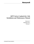
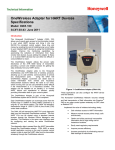
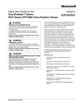
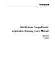
OneWireless Gauge Reader User's Manual 34-XY-25-31 Revision 1 April 2009 Notices and Trademarks Copyright 2009 by Honeywell International Inc. Revision 1 April 2009 While this information is presented in good faith and believed to be accurate, Honeywell disclaims the implied warranties of merchantability and fitness for a particular purpose and makes no express warranties except as may be stated in its written agreement with and for its customers. In no event is Honeywell liable to anyone for any indirect, special or consequential damages. The information and specifications in this document are subject to change without notice. Honeywell and OneWireless are registered trademarks of Honeywell International Inc. Other brand or product names are trademarks of their respective owners. Copyrights Copyright 2009 by Honeywell. All rights reserved. The information in this document is subject to change without notice. While reasonable precautions have been taken, Honeywell assumes no responsibility for any errors that may appear in this document. No part of this document may be copied or reproduced in any form or by any means without the prior written consent of Honeywell. Disclaimer HONEYWELL MAKES NO WARRANTY OF ANY KIND, EXPRESS OR IMPLIED, WITH REGARD TO THIS MATERIAL, INCLUDING, BUT NOT LIMITED TO, THE IMPLIED WARRANTIES OF MERCHANTABILITY AND FITNESS FOR A PARTICULAR PURPOSE. Honeywell reserves the right to make changes without further notice to the materials described herein. Honeywell does not assume any liability arising out of the application or use of any product described herein. Honeywell does not authorize its products for use in mission or safety critical systems or where a malfunction or failure may reasonably be expected to result in significant injury to the user, property damage or economic loss. The inclusion of Honeywell product in mission or safety critical system applications implies that the user assumes all risk of such use and in doing so indemnifies Honeywell and its supplier(s) against all charges. In no event is Honeywell liable to anyone for any indirect, special or consequential damages. Patents The products and technologies described in this document have patents pending. Honeywell Process Solutions 2500 West Union Hills Phoenix, AZ 85027 1-800 343-0228 ii OneWireless Gauge Reader User's Manual April 09 Notices and Trademarks References About This Document This document describes Safety, Operation and Maintenance of the OneWireless Gauge Reader. Full mounting, installation and wiring are covered in the Installation Manual. There is also the OneWireless Gauge Reader Application Gateway manual that covers the collection of data, the setup of the system. Honeywell does not recommend using devices for critical control where there is a single point of failure or where single points of failure result in unsafe conditions. OneWireless is targeted at open loop control, supervisory control, and controls that do not have environmental or safety consequences. As with any process control solution, the end-user must weigh the risks and benefits to determine if the products used are the right match for the application based on security, safety, and performance. Additionally, it is up to the end-user to ensure that the control strategy sheds to a safe operating condition if any crucial segment of the control solution fails. Disclaimer and Patent Protection DISCLAIMER. Products are not designed, intended, or authorized for use in weapons systems, nuclear installations, life-support or other medical systems, pollution control, hazardous substance management, or other systems in which malfunction could be reasonably expected to cause significant bodily harm, property damage, or economic loss. The use of Honeywell products in such systems implies that the user assumes all risks of such use. Protected by Patents Pending in the United States and other countries by Honeywell. Reference Information Document Name OneWireless Gauge Reader User Manual Document ID Revision Number Publication Date 34-XY-25-31 1 April 09 References The following list identifies all documents that may be sources of reference for material discussed in this publication. Document Name Document Part Number OneWireless Gauge Reader Specification 34-XY-03-37 OneWireless Gauge Reader Installation Manual 34-XY-25-32 OneWireless Gauge Reader Application Gateway Manual 34-XY-25-33 OneWireless Gauge Reader Model Selection Guide 34-XY-16-80 World Wide Web Honeywell Solution Support Online: http://www.honeywell.com/ps Elsewhere Call your nearest Honeywell office. Training Classes Honeywell Automation College: http://www.automationcollege.com April 09 OneWireless Gauge Reader User's Manual iii Symbol Definitions The following table lists those symbols used in this document to denote certain conditions. Symbol Definition ATTENTION: Identifies information that requires special consideration. TIP: Identifies advice or hints for the user, often in terms of performing a task. CAUTION Indicates a situation which, if not avoided, may result in equipment or work (data) on the system being damaged or lost, or may result in the inability to properly operate the process. CAUTION: Indicates a potentially hazardous situation which, if not avoided, may result in minor or moderate injury. It may also be used to alert against unsafe practices. CAUTION symbol on the equipment refers the user to the product manual for additional information. The symbol appears next to required information in the manual. WARNING: Indicates a potentially hazardous situation, which, if not avoided, could result in serious injury or death. WARNING symbol on the equipment refers the user to the product manual for additional information. The symbol appears next to required information in the manual. WARNING, Risk of electrical shock: Potential shock hazard where HAZARDOUS LIVE voltages greater than 30 Vrms, 42.4 Vpeak, or 60 VDC may be accessible. ESD HAZARD: Danger of an electro-static discharge to which equipment may be sensitive. Observe precautions for handling electrostatic sensitive devices. Protective Earth (PE) terminal: Provided for connection of the protective earth (green or green/yellow) supply system conductor. Functional earth terminal: Used for non-safety purposes such as noise immunity improvement. NOTE: This connection shall be bonded to Protective Earth at the source of supply in accordance with national local electrical code requirements. Earth Ground: Functional earth connection. NOTE: This connection shall be bonded to Protective Earth at the source of supply in accordance with national and local electrical code requirements. Chassis Ground: Identifies a connection to the chassis or frame of the equipment shall be bonded to Protective Earth at the source of supply in accordance with national and local electrical code requirements. continued iv OneWireless Gauge Reader User's Manual April 09 Symbol Description For radio equipment used in the European Union in accordance with the R&TTE Directive the CE Mark and the notified body (NB) identification number is used when the NB is involved in the conformity assessment procedure. The alert sign must be used when a restriction on use (output power limit by a country at certain frequencies) applies to the equipment and must follow the CE marking. April 09 OneWireless Gauge Reader User's Manual v vi OneWireless Gauge Reader User's Manual April 09 Table of Contents 1) INTRODUCTION ..................................................................................................... I 2) SAFETY PRECAUTIONS ....................................................................................... I 3) WGR OVERVIEW ................................................................................................... I 4) LCD DISPLAY AND PUSH BUTTONS.................................................................. 2 4.1 Data Sampling ...............................................................................................................................3 5) MONITORING SYSTEM OVERVIEW .................................................................... 4 6) INSTALLATION CONSIDERATIONS.................................................................... 5 6.1 WGR Installation............................................................................................................................5 6.1.1 6.1.2 6.2 7) Verify gauge functionality........................................................................................................................8 Considerations for Mounting the WGR ...................................................................................................9 WGR Application Gateway Installation .....................................................................................10 WGR CONFIGURATION, CALIBRATION, AND COMMISSIONING .................. 10 7.1 8) WGR Node Identification ............................................................................................................10 WGR OPERATION .............................................................................................. 10 8.1 Turning the WGR On and Off .....................................................................................................12 8.2 Setting the Sampling Rate of the WGR .....................................................................................12 8.2.1 8.2.2 8.2.3 Manual instantaneous reading..............................................................................................................12 Normal Sample Mode ...........................................................................................................................12 Default short term data collection intervals. ..........................................................................................12 Accessing Informative Data Parameters in the WGR.........................................................................13 8.3.1 8.3.2 8.3.3 MAC Address .......................................................................................................................................13 IP Address ............................................................................................................................................13 All other Data Menu Items ....................................................................................................................13 Configuration and Setup Menus...........................................................................................................14 9) WGR APPLICATION GATEWAY OPERATION .................................................. 14 10) CARE AND MAINTENANCE ............................................................................... 14 10.1 Calibration ................................................................................................................................14 10.2 Battery Life ...............................................................................................................................14 April 09 OneWireless Gauge Reader User's Manual vii 11) TROUBLESHOOTING ......................................................................................... 15 11.1 The WGR screen is blank and will not turn on. ................................................................... 15 11.2 The WGR display shows ERROR in the upper left corner.................................................. 15 12) PRODUCT DISPOSAL......................................................................................... 15 13) WARRANTY INFORMATION............................................................................... 15 14) SUPPORT SERVICES / CONTACT INFORMATION........................................... 16 viii OneWireless Gauge Reader User's Manual April 09 1) Introduction Thank you for purchasing the Honeywell OneWireless Gauge Reader (WGR). Please read this guide thoroughly before using the WGR. The WGR is not a stand-alone product. 2) Safety Precautions Do not immerse the WGR in water. Always wear personal protective equipment appropriate to the system on which the WGR is being installed. Do not try to repair the WGR yourself as it contains no user-serviceable parts. Contact a qualified service technician for repairs. See the Support section below for details. 3) WGR Overview The OneWireless Gauge Reader (WGR) is designed to read manual gauges, is battery-powered and transmits measurement data to a data acquisition system. The WGR is designed to be noninvasive. It is attached over the face of an existing analog gauge, as shown in Figure 1. Each WGR comes with an adapter that is sized for the gauge it is reading. Adapters range in size to fit over gauge faces that are 1.5 to 4.5 inches in diameter. Figure 1 : OneWireless Gauge Reader The WGR optically reads the gauge face and wirelessly transmits the reading. This value is also displayed locally on the LCD. A representation of the LCD is shown in Figure 2. April 09 OneWireless Gauge Reader User's Manual 1 4) LCD Display and Push Buttons Figure 2 : WGR LCD Display and Control Buttons A. B. C. D. E. F. G. H. I. J. SAMPLE Icon ERROR Icon: Bar Graph Numeric Display Antenna Icon Battery Level Alpha-numeric Display Left Button Center Button Right Button Displayed when a new reading is being captured and converted Displayed when an error condition is detected Indicates percent of full-scale reading Displays the converted reading value Displayed when a wireless connection has been established Displays percentage of battery life remaining Displays the reading units or diagnostic messages Left or escape button, depending on menu context Select/Enter/Sample button, depending on menu context Right button to navigate through LCD menus The WGR is specifically configured to the gauge that it is reading. During installation, the WGR is positioned per the customer specifications. The WGR can be positioned at an offset to the gauge. For example, a gauge could be mounted at an angle for a gas bottle monitoring system, but the WGR could be positioned upright for easier reading. Refer to Figure 3 as an example. Once the WGR is in position, it is secured in place for calibration. The range of the gauge, units of measure, and any offsets are entered into the WGR. The WGR is calibrated by a trained installer, and ready for use. 2 OneWireless Gauge Reader User's Manual April 09 4.1 Data Sampling The WGR samples the gauge reading in one of three specified intervals. Figure 3 : WGR being placed horizontally on gauge that is mounted at an angle 1) Manual instantaneous reading. a) The user can request an instant reading, by pressing the center button of the WGR. 2) Routine data collection. a) The WGR is programmed by the installer to sample the gauge reading at a regular interval, usually between 5 minutes and one hour. b) This is referred to as Normal Sample Mode. 3) Short-term data collection. a) The WGR supports an increased sample rate for short term high resolution data collection or for diagnostics. b) These modes are referred to as Fast Sample Mode and Medium Sample Mode. i) Fast Sample Mode takes a reading every 5 seconds for a duration of 5 minutes. The WGR then goes back into Normal Sample Mode. ii) Medium Sample Mode takes a reading every 30 seconds for a duration of 8 hours. The WGR then goes back into Normal Sample Mode. c) Refer to the Operation section below for details on enabling each of these short-term modes. April 09 OneWireless Gauge Reader User's Manual 3 5) Monitoring System Overview The OneWireless Gauge Reader is part of an overall monitoring system, and integrates seamlessly with other OneWireless components. The WGR Application Gateway collects the data from all of the WGRs in the system. The WGR Application Gateway is connected to the plant network, and the data can be accessed through the Web Server or OPC Server functionality included on the WGR Application Gateway. Refer to Figure 4 for a high level system connection diagram. Figure 4 : OneWireless System Diagram Including WGRs and the WGR Application Gateway The WGR normally communicates through one or more Multinodes in order to send data to the WGR Application Gateway. The data on the WGR Application Gateway can be accessed by any other device on the plant Ethernet using either the supported OPC interface or the Web Server interface. During installation, the installer will use a Handheld Configuration Tool to calibrate and commission each WGR. The Handheld Tool can talk directly to the WGR, and can also talk through the Multinode if desired, for additional functionality and data access. 4 OneWireless Gauge Reader User's Manual April 09 6) Installation Considerations 6.1 WGR Installation The WGR mounts to a gauge using one of several different size and type of mounting adapter. The installer will determine the proper adapter required for each gauge, and the WGR will be ordered with the adapter pre-mated to the WGR main body. Please refer to Figues 6-9 for examples of mounting adapter kits that allow the WGR to support a wide variety of gauges. April 09 OneWireless Gauge Reader User's Manual 5 Figure 5 : WGR Mounting Adapters 6 OneWireless Gauge Reader User's Manual April 09 Figure 6 shows an example of a special additional adapter that is used for Magnehelic and Photohelic gauges, due to their unique shape. Figure 6 : Exploded View of Magnehelic/Photohelic Mounting Adapter Figure 7 shows an example of a special adapter that is used to mount to process gauges, since they have a sloped surface along their circumference that would normally be difficult for a standard style adapter to grasp. Figure 7 : Exploded View of a Process Gauge Mounting Adapter March 09 OneWireless Gauge Reader User's Manual 7 Figure 8 shows an exploded view of a large adapter mating with a special panel mount adapter. This adapter is used when the gauge is mounted flush in a panel, and there is no way for the regular adapter to grasp the outside of the gauge. The panel mount adapter uses a ring of 3M Dual-Lock Fastener material with VHB (very high bond) adhesive to adhere to the panel surrounding the gauge. Figure 8 : Exploded View of Panel Mount Adapter 6.1.1 Verify gauge functionality 1) Prior to installation, ensure that there are no visual obstructions between the WGR and gauge face (stickers, marks, etc.). a) Use an appropriate cleaning agent, such as isopropyl alcohol to clean the gauge face prior to installing the WGR. b) Also, make sure there are no deep scratches on the gauge window that could affect the WGR’s imaging system. c) For liquid filled gauges, please make sure the gauge is filled as completely as possible, so that the liquid level line does not obscure the needle, and so there are no liquid droplets on the gauge face. Figure 9 : Examples of a Clean Gauge and Two Visually Impaired Gauges 2) Calibrate the mechanical gauge itself, if required. a) The WGR reading is only as accurate as the gauge it is reading, since the WGR views the gauge needle position. 8 OneWireless Gauge Reader User's Manual April 09 6.1.2 Considerations for Mounting the WGR 1) Determine if the gauge is a free-standing gauge or a panel mounted gauge, since this will determine the type of mounting adapters and mounting method required. 2) For a panel mounted gauges, there are a few options depending on the size and type of panel mounted gauge. a) For Magnehelic and Photohelic panel mounted gauges, a special adapter is provided to securely fasten to these gauges. i) The gauge will need to be loosened slightly from its current mount in order to provide room to fasten the mounting adapter to the font lip of the gauge. b) For other panel mounted gauges, different adapters are provided that adhere to the panel surface around the circumference of the gauge. i) Make sure that the panel surface is clean (use isopropyl alcohol), smooth, and that there is enough available surface area for the adapter without interference from neighboring gauges or other objects. ii) Generally an area of at least 5/8 in. (16mm) wide is required around the gauge’s outside circumference. (1) Consult with your installer for specific mechanical information for the panel mount adapter. 3) For normal free-standing gauges, there are a variety of WGR mounting adapters available a) Refer to the sizing chart below to determine if the desired gauge falls between the Min and Max Outside Diameter specified in the table. b) The adapters are able to flex to accommodate minor variations in diameter for each adapter size. c) Silicone shim bands can also be used by the installer to help create a proper fit. d) Silicone shim bands can also be used on gauges that have a very narrow lip, in order to provide a larger surface area for the adapter to grasp. Figure 10 : Table of Gauge Adapter Sizes March 09 OneWireless Gauge Reader User's Manual 9 6.2 1) 2) 3) 4) 5) WGR Application Gateway Installation Application Gateway location a) The WGR Application Gateway will need to be located in a climate controlled room, preferably where other servers are housed. b) The Application Gateway can be mounted on the wall with an optional wall mounting bracket, or it can be placed on a sturdy horizontal surface. The Application Gateway will need access to a power outlet and an Ethernet connection. The WGR Application Gateway requires a static IP Address assignment from the IT department, so that the Application Gateway can be easily accessed by both the WGRs and by any clients retrieving data from the Application Gateway. You can optionally connect the Application Gateway to an uninterruptable power source (UPS) in order to ensure that there is no loss or corruption of data in the event of a facilities power outage. Please refer to the Installation Guide and OneWireless Gauge Reader Application Gateway User's Manual for additional installation and operating instructions. 7) WGR Configuration, Calibration, and Commissioning After the WGR is properly mounted to a gauge, it must be configured, calibrated, and commissioned. These steps must be performed by a qualified service technician, and are not covered in this manual. Please see the Support section below for contact information. 7.1 WGR Node Identification Each WGR has various identifiers used for different purposes. • • • The MAC (Media Access Control) Address can be considered a unique identification number for each WGR. o The MAC address is shown in the LCD Data menu, and is also printed on a label on the bottom of the WGR. The IP (Internet Protocol) Address, is another identifier for the WGR, but it is not guaranteed to be universally unique. o It is used to address network messages to the WGR. There is also a NodeID which is only used on the WGR Application Gateway, and is a short and simple ID number that is assigned to reference each unique MAC Address for more convenient data access. o The NodeID can only be viewed on the Application Gateway, and is not used on the WGR itself. 8) WGR Operation There are various functions that can be performed both through the web interface and at the WGR using the push-buttons and LCD. This section describes how to perform functions at the WGR. Please refer to Figure 11 for information about navigating through the WGR’s LCD Menus. 10 OneWireless Gauge Reader User's Manual April 09 Figure 11 : WGR LCD Menu Navigation April 09 OneWireless Gauge Reader User's Manual 11 8.1 Turning the WGR On and Off After installation, the WGR should never be turned off. The off state is only provided to save additional battery power during shipping and before the WGR is installed on a gauge. Please consult with your authorized installer for powering the WGR on and off. 8.2 Setting the Sampling Rate of the WGR 8.2.1 1) 2) 3) Manual instantaneous reading To request a one-time instant reading, press the “●” button on the WGR. The WGR will show SAMPLE in the top left corner briefly. Then SAMPLE disappears, then the reading on the LCD will be updated with the latest value. 8.2.2 Normal Sample Mode Whenever the WGR is on and operating in Normal Sample Mode, it samples based on the routine data collection rate. This rate is between 0 and 65535 seconds (approximately 18 hours). This value is defined by the installer or user, and can be changed at the WGR. 1) 2) 3) 4) 5) 6) 7) 8) 8.2.3 Press “►” to access the WGR menu. Press “►” until the bottom right side of the display reads DATA. Press “●” to select this option. a) Press “◄” if you need to cancel and return to the main screen. Once in the DATA menu, press “►” until you reach the UPDTE submenu. Press “●” to edit the update rate. a) ** This feature is password protected. ** Enter the WGR user password sequence: “◄,►,◄,●,►”. The bottom right side of the display should now read UPDTE? Use the “◄” and “►” buttons to change the update rate and press “●” to save the change and return to the UPDTE menu. Default short term data collection intervals. In addition to the routine data collection rate, there are two pre-programmed short term data collection intervals associated with the WGR: FAST and MED (medium). 8.2.3.1 FAST The FAST sample mode collects data at a 5-second interval for a 5-minute duration. While the WGR is in the FAST sample mode, the units of data will have an “*” at the end. 1) Press “►” to access the WGR menu. a) The bottom right side of the display should read FAST. 2) Press “●” to select this option. a) Press “◄” to cancel and return to the main screen. 3) Press “◄” at any time during this modified sample mode to cancel and return to the normal sample mode. 4) Otherwise, the mode will timeout after 8 hours and automatically return to normal sample mode. 12 OneWireless Gauge Reader User's Manual April 09 8.2.3.2 MED The MED sample mode collects data at a 30-second interval for an 8-hour duration. While the WGR is in the MED sample mode, the units of data will have an “m” at the end. 1) Press “►” to access the WGR menu. 2) Press “►” again. a) The bottom right side of the display should read MED. 3) Press “●” to select this option. a) Press “◄” to cancel and return to the main screen. 4) Press “◄” at any time during this modified sample mode to cancel and return to the normal sample mode. 5) Otherwise, the mode will timeout after 8 hours and automatically return to normal sample mode. Accessing Informative Data Parameters in the WGR Several data parameters can be viewed, but not edited in the WGR’s DATA menu. The following parameters are available: • • • • • • • Receive Signal Strength Indicator (RSSI) WGR MAC Address WGR IP Address Internal Temperature Firmware Version Serial Number Hardware Version 8.3.1 MAC Address 1) Press “►” to access the WGR menu. 2) Press “►” until the bottom right side of the display reads DATA. 3) Press “●” to select this option. 4) Press “►” until the bottom right side of the display reads MAC. 5) Press “●” to view the MAC Address 6) Use the “►” button to scroll through the 6 screens of MAC Address digits. 7) Press “◄” at any time to return to the DATA menu. 8.3.2 IP Address 1) Press “►” to access the WGR menu. 2) Press “►” until the bottom right side of the display reads DATA. 3) Press “●” to select this option. 4) Press “►” until the bottom right side of the display reads IP Ad. 5) Press “●” to view the IP Address 6) Use the “►” button to scroll through the 4 screens of IP Address digits. 7) Press “◄” at any time to return to the DATA menu. 8.3.3 All other Data Menu Items Follow these steps in order to access all of the other parameters available in the DATA menu: 1) 2) 3) 4) 5) 6) 7) Press “►” to access the WGR menu. Press “►” until the bottom right side of the display reads DATA. Press “●” to select this option. Press “►” to scroll through different data parameters until you reach the desired parameter. The value of the parameter will appear on the LCD display. Press “◄” to exit the menu and return to the normal operating display screen. If no button is pressed for 10 seconds, the WGR will automatically return to the normal operating display screen April 09 OneWireless Gauge Reader User's Manual 13 Configuration and Setup Menus The CONFG and SETUP menus are primarily restricted and for use by qualified service technicians to configure and install the WGR. 9) WGR Application Gateway Operation Please refer to the WGR Application Gateway ver User Manual for information about accessing the data from the WGR Application Gateway using the Web or OPC interface. 10) Care and Maintenance 10.1 Calibration Calibration is performed when the WGR is configured during installation. Calibration is performed based on the position of the WGR with respect to the gauge face. Re-calibration is not required if the WGR is not removed from gauge or the position of the WGR with respect to the gauge face has not shifted. If the WGR is removed from gauge face, contact a service technician to re-calibrate the WGR. Simply repositioning the WGR on the gauge may result in erroneous readings. See the Support section below for contact information. 10.2 Battery Life Each WGR comes with two lithium batteries. Battery status can be monitored on the LCD of the WGR, or through the OPC or Web interface connected to the WGR Application Gateway. Battery change-out must be performed by a qualified service technician, since calibration must be verified after the batteries are replaced to ensure reliable operation. See the Support section below for contact information. The battery life of the WGR is dependent on the sampling frequency and operating environment. Typical ranges for room temperature applications are listed below. Extended operation at cold temperatures will reduce the expected battery life. Sampling Frequency Estimated Battery Life Internal Battery Voltage 2.0V 3.0V 1 sample per minute 0.3 years (@ -20C) 0.6 years 1 sample per 5 minutes 0.5 years (@ -20C) 1 year 1 sample per 15 minutes 1 year (@ -20C) 2 years 1.5 years (@ -20C) 3 years 1 sample per 18 hours 14 OneWireless Gauge Reader User's Manual April 09 11) Troubleshooting The most common problems with the WGR are listed below: 11.1 The WGR screen is blank and will not turn on. Please contact a qualified service technician. See the Support section below for contact information. 11.2 The WGR display shows ERROR in the upper left corner. The ERROR message appears on the LCD when the WGR is having a problem obtaining a reading from the gauge. Common causes for this are: 1) The WGR has been moved from its configured position. a. If you think the WGR has been moved or knocked out of place, contact a qualified service technician to re-calibrate the WGR. b. If the WGR is installed on equipment that is prone to vibration, the WGR may have slipped out of place. Contact a qualified service technician to re-secure and re-calibrate the WGR. 2) There WGR is having difficulty reading the gauge due to obstruction or vibration a. If the gauge is installed outdoors, condensate buildup inside the gauge itself may impact the WGR from obtaining a good reading. If possible, install a liquid-filled gauge and have the WGR reinstalled and re-calibrated. b. If the gauge has multiple needles, the WGR may have an issue identifying which needle to read. Try to install a gauge with only one needle. This issue should be raised by the service technician during installation. c. If the gauge only has one needle, but there is nothing to distinguish one end of the needle from the other, the WGR may have problems obtaining a reading. If possible, install a gauge that has a different type of pointer. This issue should be raised by the service technician during installation. d. If the equipment that the gauge is monitoring causes the gauge needle to vibrate very rapidly (such as some compressors), then the WGR may have difficulty capturing a clean reading from the gauge. In this case, please replace the gauge with a dampened or liquid-filled gauge to slow the motion of the needle. Then have the WGR re-installed and re-calibrated by a qualified service technician. 3) The pointer of the gauge has broken. a. In some cases, gauges that are installed on equipment that are prone to vibration can break needles. If you suspect this is the problem, contact a qualified service technician. If you remove the WGR yourself to determine if this is the issue, you will still need to have the WGR re-calibrated. 4) The wireless connectivity of the WGR to the Application Gateway is weak. a. In some cases, the wireless signal strength of a WGR to the Application Gateway is affected by facility changes. Weak connectivity from the WGR to the Application Gateway will cause an error message. The ERROR message should also be associated with a missing ANTENNA icon in the lower right hand corner of the LCD. Contact a qualified service technician if this problem occurs. If you have additional problems, please contact us. See the Support section below for contact information. 12) Product Disposal The WGR is recycled by Honeywell. See the Support section below for contact information. 13) Warranty Information Every product comes with a full one-year parts and labor warranty. April 09 OneWireless Gauge Reader User's Manual 15 14) Support Services / Contact Information For application assistance, current specifications, pricing, or name of the nearest Authorized Distributor, contact one of the offices below. ASIA PACIFIC Control Products Asia Pacific Headquarters Phone: +(65) 6355-2828 Fax: +(65) 6445-3033 Asia Pacific Global Technical Support Field Instruments Phone: +65 6580 3156 Fax: +65 6445-3033 Process Instruments Phone: (603) 76950 4777 Fax: (603) 7958 8922 Australia Honeywell Limited Phone: +(61) 7-3846 1255 FAX: +(61) 7-3840 6481 Toll Free 1300-36-39-36 Toll Free Fax: 1300-36-04-70 China – PRC - Beijing Honeywell China Inc. Phone: +(86-10) 8458-3280 Fax: +(86-10) 8458-4650 China – PRC - Shanghai Honeywell China Inc. Phone: (86-21) 5257-4568 Fax: (86-21) 6237-2826 China – PRC - Chengdu Honeywell China Inc. Phone: +(86-28) 8678-6348 Fax: +(86-28) 8678-7061 China – PRC - Xi’an Honeywell China Ltd - Xi’an. Phone: +(86-29) 8833-7490 Fax: +(86-29) 8833-7489 China – PRC - ShenzhenHoneywell China Inc. Phone: +(86) 755-2518-1226 Fax: +(86) 755-2518-1221 Indonesia PT Honeywell Indonesia Phone: +(62) 21-535-8833 FAX: +(62) 21-5367 1008 India Automation India Ltd. Honeywell Ltd. Phone:+(91) 5603-9400 Fax: +(91) 5603-9600 Japan Honeywell Inc. Phone: +(81) 3 6730 7150 Fax: +(81) 3 6730 7228 Malaysia Honeywell Engineering Sdn Bhd Phone: +(60-3) 7950-4776 Fax: +(60-3) 7958-8922 New Zealand Honeywell Limited Phone: +(64-9) 623-5052 Fax: +(64-9) 623-5060 Toll Free (0800) 202-088 Philippines Honeywell Systems (Philippines) Inc. Phone: +(63-2) 633-283031/ 636 1661-62 Fax: +(63-2) 638-4013 Singapore Honeywell Pte Ltd. Phone: +(65) 6580 3278 Fax: +(65) 6445-3033 South Korea Honeywell Korea Co Ltd Phone: +(822) 799 6315 Fax: +(822) 792 9015 Thailand Honeywell Systems (Thailand) Ltd. Phone: +(662) 693-3099 FAX: +(662) 693-3089 Taiwan R.O.C. Honeywell Taiwan Ltd. Phone: +(886-2) 22451000 FAX: +(886-2) 2245-3241 SE Asia Countries see Honeywell Pte Ltd (Singapore) for: Pakistan, Cambodia, Guam, Laos, Myanmar, Vietnam, East Timor SE Asia Countries see Honeywell Automation India Ltd for: Bangladesh Nepal Sri Lanka EUROPE Austria Honeywell Austria GmbH Phone: +43 (316)400123 FAX: +43 (316)40017 Belgium Honeywell SA/NV Phone: +32 (0) 2 728 24 07 FAX: +32 (0) 2 728 22 45 Bulgaria Honeywell EOOD Phone: +(359) 2 40 20 900 FAX: +(359) 2 40 20 990 Honeywell Process Solutions Honeywell 2500 W. Union Hill Drive Phoenix, Arizona 85027 Czech Republic Honeywell spol. s.r.o. Phone: +420 242 442 232 FAX: +420 242 442 131 Slovak Republic Honeywell s.r.o. Phone: +421-2-58247 410 FAX: +421-2-58247 415 Denmark Honeywell A/S Phone: +(45) 39 55 55 55 FAX: +(45) 39 55 55 58 Spain Honeywell S.A. Phone: +34 (0)91313 61 00 FAX: +34 (0)91313 61 30 Finland Honeywell OY Phone: +358 (0)20752 2753 FAX: +358 (0) 20752 2751 Sweden Honeywell AB Phone: +(46) 8 775 55 00 FAX: +(46) 8 775 56 00 France Honeywell SA Phone: +33 (0)1 60198075 FAX: +33 (0)1 60198201 Germany Honeywell AG Phone: +49 (69)8064-299 FAX: +49 (69)806497336 Hungary Honeywell Kft. Phone: +36-1-451 4300 FAX: +36-1-451 4343 Italy Honeywell S.p.A. Phone:+390292146307 FAX: +39 0292146377 The Netherlands Honeywell B.V. Phone: +31 (0) 20 5656200 FAX: +31 (0) 20 5656210 Norway Honeywell A/S Phone: (45) 39 55 55 55 Poland Honeywell Sp. zo.o Phone: +48-22-6060900 FAX: +48-22-6060901 Portugal Honeywell Portugal Lda Phone: +351 21 424 5000 FAX: +351 21 424 50 99 Romania Honeywell Bucharest Phone: +40 (0) 21 2316437 FAX: +40 (0) 21 2316439 Russian Federation (RF), ZAO "Honeywell" Phone: +7 (095) 796 98 00 FAX: +7 (495) 797 99 64 Switzerland Honeywell AG Phone: +41 18552448 FAX: +(41) 1 855 24 45 Turkey Honeywell Turkey A.S. Phone: +90 216 578 71 00 FAX: +90 216 575 66 35 Ukraine Honeywell Tel: +380-44-201 44 74 Fax: +380-44-201-44-75 United Kingdom Honeywell Control Systems Ltd. Phone: +44 (0)1344 655251 FAX: +44 (0) 1344 655554 MIDDLE EAST Abu Dhabi U A E Middle East Headquarters Honeywell Middle East Ltd. Phone: +971 2 4041246 FAX: +971 2 4432536 Sultanate of Oman Honeywell & Co Oman LLC Phone: +968 24 701153/ Ext.33 FAX +968 24 787351 AFRICA Mediterranean & African Distributors Honeywell SpA Phone: +39 (02) 250 10 604 FAX: +39 (02) 250 10 659 South Africa (Republic of) and sub saharan Honeywell Southern Africa Honeywell S.A. Pty. Ltd. Phone: +27 11 6958000 FAX +27 118051504 NORTH AMERICA Canada Honeywell LTD Phone: 1-800-737-3360 FAX: 1-800-565-4130 USA Honeywell Process Solutions, Phone: 1-800-343-0228 FAX: 1-717-771-8251 Email:sc-cp-appssales@ honeywell.com LATIN AMERICA Argentina Honeywell S.A.I.C. Phone: +(54-11) 4383-3637 FAX: +(54-11) 4325-6470 Brazil Honeywell do Brasil & Cia Phone: +(55-11) 7266-1900 FAX: +(55-11) 7266-1905 Chile Honeywell Chile, S.A. Phone: +(56-2) 233-0688 FAX: +(56-2) 231-6679 Mexico Honeywell S.A. de C.V. Phone: +(52) 55 5259-1966 FAX: +(52) 55 5570-2985 Saudia Arabia Honeywell Turki Arabia Ltd Jubail Office Phone: +966-3-341-0140 Fax: +966-3-341-0216 Honeywell - ATCO Dammam Office Phone: 0096638304584 Fax: 0096638338059 Puerto Rico Honeywell Inc. Phone: +(809) 792-7075 FAX: +(809) 792-0053 Kuwait Honeywell Kuwait KSC Phone:+965 242 1327 to 30 Fax: +965 242 8315 And Phone: +965 326 2934/1821 Fax: +965 326 1714 Venezuela Honeywell CA Phone: +(58-2) 238-0211 FAX: +(58-2) 238-3391 34-XY-25-31 Rev.1 April 2009 ©2009 Honeywell International Inc. Trinidad Honeywell Inc. Phone: +(868) 624-3964 FAX: +(868) 624-3969