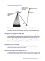
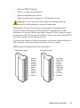
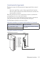
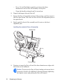
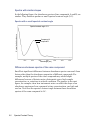
1
2998 Photodiode Array Detector Operator’s Guide 71500121902/Revision C Copyright © Waters Corporation 2010 All rights reserved Copyright notice © 2010 WATERS CORPORATION. PRINTED IN THE UNITED STATES OF AMERICA AND IN IRELAND. ALL RIGHTS RESERVED. THIS DOCUMENT OR PARTS THEREOF MAY NOT BE REPRODUCED IN ANY FORM WITHOUT THE WRITTEN PERMISSION OF THE PUBLISHER. The information in this document is subject to change without notice and should not be construed as a commitment by Waters Corporation. Waters Corporation assumes no responsibility for any errors that may appear in this document. This document is believed to be complete and accurate at the time of publication. In no event shall Waters Corporation be liable for incidental or consequential damages in connection with, or arising from, its use. Trademarks Waters and Alliance are registered trademarks of Waters Corporation, and Empower, MassLynx, SAT/IN, TaperSlit, and “THE SCIENCE OF WHAT’S POSSIBLE.” are trademarks of Waters Corporation. Tygon is a registered trademark of Saint-Gobain Ceramics & Plastics, Inc. Other registered trademarks or trademarks are the sole property of their owners. ii Customer comments Waters’ Technical Communications department invites you to tell us of any errors you encounter in this document or to suggest ideas for otherwise improving it. Please help us better understand what you expect from our documentation so that we can continuously improve its accuracy and usability. We seriously consider every customer comment we receive. You can reach us at [email protected]. Contacting Waters ® Contact Waters with enhancement requests or technical questions regarding the use, transportation, removal, or disposal of any Waters product. You can reach us via the Internet, telephone, or conventional mail. Waters contact information Contacting medium Information Internet The Waters Web site includes contact information for Waters locations worldwide. Visit www.waters.com. Telephone and fax From the USA or Canada, phone 800 252-HPLC, or fax 508 872 1990. For other locations worldwide, phone and fax numbers appear in the Waters Web site. Conventional mail Waters Corporation 34 Maple Street Milford, MA 01757 USA Safety considerations Some reagents and samples used with Waters instruments and devices can pose chemical, biological, and radiological hazards. You must know the potentially hazardous effects of all substances you work with. Always follow iii Good Laboratory Practice, and consult your organization’s safety representative for guidance. Safety advisories Consult Appendix A for a comprehensive list of warning and caution advisories. Operating this instrument When operating this instrument, follow standard quality-control (QC) procedures and the guidelines presented in this section. Applicable symbols Symbol Definition Manufacturer Authorized representative of the European Community Confirms that a manufactured product complies with all applicable European Community directives Australia C-Tick EMC Compliant Confirms that a manufactured product complies with all applicable United States and Canadian safety requirements Consult instructions for use Audience and purpose This guide is intended for personnel who install, operate, and maintain the Waters 2998 Photodiode Array (PDA) detector. iv Intended use of the 2998 Photodiode Array detector Waters designed the 2998 Photodiode Array detector to analyze and monitor various types of compounds. The 2998 PDA detector is for research use only. Calibrating To calibrate LC systems, follow acceptable calibration methods using at least five standards to generate a standard curve. The concentration range for standards should include the entire range of QC samples, typical specimens, and atypical specimens. When calibrating mass spectrometers, consult the calibration section of the operator’s guide for the instrument you are calibrating. In cases where an overview and maintenance guide, not operator’s guide, accompanies the instrument, consult the instrument’s online Help system for calibration instructions. Quality-control Routinely run three QC samples that represent subnormal, normal, and above-normal levels of a compound. Ensure that QC sample results fall within an acceptable range, and evaluate precision from day to day and run to run. Data collected when QC samples are out of range might not be valid. Do not report these data until you are certain that the instrument performs satisfactorily. ISM classification ISM Classification: ISM Group 1 Class B This classification has been assigned in accordance with CISPR 11 Industrial Scientific and Medical (ISM) instruments requirements. Group 1 products apply to intentionally generated and/or used conductively coupled radio-frequency energy that is necessary for the internal functioning of the equipment. Class B products are suitable for use in both commercial and residential locations and can be directly connected to a low voltage, power-supply network. v EC authorized representative Waters Corporation (Micromass UK Ltd.) Floats Road Wythenshawe Manchester M23 9LZ United Kingdom vi Telephone: +44-161-946-2400 Fax: +44-161-946-2480 Contact: Quality manager Table of Contents Copyright notice ................................................................................................... ii Trademarks ............................................................................................................ ii Customer comments ............................................................................................ iii Contacting Waters ............................................................................................... iii Safety considerations .......................................................................................... iii Safety advisories ................................................................................................. iv Operating this instrument ................................................................................. iv Applicable symbols ............................................................................................. iv Audience and purpose......................................................................................... iv Intended use of the 2998 Photodiode Array detector......................................... v Calibrating ........................................................................................................... v Quality-control ..................................................................................................... v ISM classification .................................................................................................. v ISM Classification: ISM Group 1 Class B .......................................................... v EC authorized representative ........................................................................... vi 1 2998 PDA Detector Optics Principles ................................................ 1-1 Detector optics ................................................................................................... 1-2 Calculating absorbance ................................................................................... 1-3 Flow cell operating principles ....................................................................... 1-4 Resolving spectral data ................................................................................... 1-5 Measuring light at the photodiode array .................................................... Optimizing the signal-to-noise ratio ............................................................... Optimizing filter constants ............................................................................. Selecting the appropriate sampling rate ........................................................ 1-6 1-7 1-7 1-7 Computing absorbance data points .............................................................. 1-9 Dark current .................................................................................................... 1-9 Table of Contents vii Reference spectrum ......................................................................................... 1-9 Data averaging................................................................................................. 1-9 Filtering data ................................................................................................. 1-12 Reference wavelength compensation ............................................................ 1-13 2 Setting Up the Detector ........................................................................ 2-1 Before you begin ............................................................................................... 2-2 Unpacking and inspecting .............................................................................. 2-2 Laboratory site selection ................................................................................ 2-3 Detector dimensions ........................................................................................ 2-4 Connecting to the electricity source ............................................................ 2-4 Making signal connections ............................................................................. Connecting the Ethernet cable........................................................................ Network installation guidelines...................................................................... Connecting to other instruments .................................................................... 2-5 2-6 2-7 2-8 Plumbing the detector ................................................................................... 2-16 Making the gas supply connection................................................................ 2-18 Starting up and shutting down the detector ............................................ Starting up the detector ................................................................................ Monitoring detector LEDs ............................................................................. Shutting down the detector ........................................................................... 2-18 2-19 2-20 2-21 Using a cuvette ................................................................................................ 2-21 3 Maintaining the Detector ..................................................................... 3-1 Contacting Waters technical service ............................................................ 3-2 Maintenance considerations .......................................................................... 3-2 Safety and handling......................................................................................... 3-2 Spare parts ....................................................................................................... 3-3 Routine Maintenance ....................................................................................... 3-3 Maintaining the flow cell ................................................................................ 3-4 Flushing the flow cell....................................................................................... 3-4 viii Table of Contents Replacing the flow cell ..................................................................................... 3-5 Replacing the lamp ........................................................................................... 3-7 Replacing the fuses ......................................................................................... 3-10 4 Diagnostic Tests and Troubleshooting ............................................. 4-1 Diagnostic tests ................................................................................................. Verifying detector calibration ......................................................................... Reading lamp energy ....................................................................................... Performing the erbium calibration ................................................................. Reading the calibration constants .................................................................. Displaying PDA detector rear panel interface connections........................... Changing the rear panel interface connections.............................................. 4-2 4-2 4-3 4-3 4-4 4-4 4-5 General troubleshooting ................................................................................. Power surges .................................................................................................... Clearing bubbles from the flow cell ................................................................ Detector troubleshooting ................................................................................. 4-6 4-6 4-7 4-7 5 Spectral Contrast Theory ..................................................................... 5-1 Comparing absorbance spectra ..................................................................... 5-2 Representing spectra as vectors ................................................................... 5-2 Vectors derived from two wavelengths ........................................................... 5-3 Vectors derived from multiple wavelengths................................................... 5-4 Spectral contrast angles .................................................................................. 5-4 Undesirable effects ........................................................................................... Detector noise................................................................................................... Photometric error............................................................................................. Solvent changes ............................................................................................... Threshold angle ............................................................................................... 5-7 5-8 5-8 5-8 5-8 A Safety Advisories .................................................................................. A-1 Warning symbols ............................................................................................... A-2 Task-specific hazard warnings........................................................................ A-2 Specific warnings ............................................................................................. A-3 Table of Contents ix Caution symbol .................................................................................................. A-5 Warnings that apply to all Waters instruments ......................................... A-6 Electrical and handling symbols ................................................................. A-12 Electrical symbols .......................................................................................... A-12 Handling symbols .......................................................................................... A-13 B Specifications ........................................................................................ B-1 C Solvent Considerations ....................................................................... C-1 Introduction ...................................................................................................... Clean solvents .................................................................................................. Solvent quality ................................................................................................. Preparation checklist....................................................................................... Water ................................................................................................................ Using buffers .................................................................................................... Tetrahydrofuran .............................................................................................. C-2 C-2 C-2 C-2 C-2 C-2 C-3 Solvent miscibility ........................................................................................... C-3 How to use miscibility numbers...................................................................... C-5 Buffered solvents ............................................................................................. C-6 Head height ....................................................................................................... C-6 Minimum tubing bend radius recommendations ..................................... C-6 Solvent viscosity ............................................................................................... C-7 Mobile phase solvent degassing ................................................................... C-7 Gas solubility ................................................................................................... C-7 Solvent degassing methods ............................................................................ Sparging ........................................................................................................... Vacuum degassing ........................................................................................... Solvent degassing considerations ................................................................... C-8 C-9 C-9 C-9 Wavelength selection .................................................................................... C-10 UV cutoffs for common solvents.................................................................... C-10 Mixed mobile phases...................................................................................... C-12 x Table of Contents Wavelength selection for chromophore detection......................................... C-13 Mobile phase absorbance............................................................................... C-14 Index ..................................................................................................... Index-1 Table of Contents xi xii Table of Contents 1 2998 PDA Detector Optics Principles To use the 2998 PDA detector effectively, you should understand the principles that underlie operation of the detector’s optics and electronics. Contents: Topic Page Detector optics 1-2 Flow cell operating principles 1-4 Resolving spectral data 1-5 Measuring light at the photodiode array 1-6 Computing absorbance data points 1-9 1-1 Detector optics The detector is an ultraviolet/visible light (UV/Vis) spectrophotometer. With a photodiode array of 512 photodiodes and an optical resolution of 1.2 nm, the detector operates within a range of 190 to 800 nm. The figure below illustrates the light path through the optics assembly of the detector. Optics assembly light path Grating Order filter Photodiode array Window Slit M1 mirror Spectrograph mirror and mask Lamp Filter flag/shutter Flow cell TP02819 The following table describes the optics assembly components. Optics assembly components 1-2 Component Function Lamp Deuterium source lamp. M1 mirror Focuses light from the deuterium source lamp. 2998 PDA Detector Optics Principles Optics assembly components (Continued) Component Function Window Used to help minimize air infiltration into the lamp housing. Filter flag/shutter Flag positions for measuring open (sample) and blocked (dark) beam energies and a third for wavelength verification. Flow cell Houses the segment of the flow path (containing eluent and sample) through which the polychromatic light beam passes. Spectrograph mirror and mask The mirror focuses light transmitted through the flow cell onto the slit at the entrance to the spectrographic portion of the optics. The mirror mask defines the size of the beam at the grating. Slit Determines wavelength resolution and intensity of light striking the photodiodes. The width of the slit is 50 µm. Grating Disperses light into bands of wavelengths and focuses them onto the plane of the photodiode array. Order filter Reduces the contribution of second-order diffraction of UV light (less than 370 nm) to the light intensity observed at visible wavelengths (greater than 370). Photodiode array A linear array of 512 photodiodes. The diode width (50 µm), together with a 50-µm slit, yields single wavelength resolution of 1.2 nm. Calculating absorbance The detector computes absorbance by subtracting the dark current (see “Dark current” on page 1-9) from the reference spectrum (reference energy) and the acquired spectrum (sample energy). Absorbance is based on the principles of Beer’s law. Beer’s law The Beer-Lambert law (commonly called Beer’s law) describes the relationship between the quantity of light of a particular wavelength arriving Detector optics 1-3 at the photodiode and the concentration of the sample passing through the flow cell. Beer’s law is expressed as A = εlc where A = dimensionless quantity measured in absorbance units ε = constant of proportionality known as the molar absorptivity l = path length in centimeters (1.0 cm in the detector’s normal flow cell) c = concentration in moles per liter Beer’s law applies only to well-equilibrated dilute solutions. It assumes that the refractive index of the sample remains constant, that the light is monochromatic, and that no stray light reaches the detector element. As concentration increases, the chemical and instrumental requirements of Beer’s law are sometimes violated, resulting in a deviation from (absorbance versus concentration) linearity. The absorbance of mobile phase can reduce the linear range. Absorbance as a function of concentration Ideal Absorbance Actual Linear range for analyte Concentration Flow cell operating principles The Waters TaperSlit™ flow cell used in the 2998 detector renders the detector baseline essentially insensitive to changes in mobile phase refractive index (RI). RI changes occur during gradient separations or result from temperature or pump-induced pressure fluctuations. To achieve RI immunity, a combination of a spherical mirror, a lens at the entrance of the flow cell, and a taper to the internal bore of the flow cell 1-4 2998 PDA Detector Optics Principles prevents light rays from striking the internal walls of the flow cell. The Waters TaperSlit flow cell, so-called because of the shape of the flow cell exit face, matches the shape of the spectrograph slit. Compared to a conventional flow cell with a cylindrical shape, the 2998 detector achieves higher light throughput for a given spectral resolution with the TaperSlit cell design. Comparison of flow cell characteristics Conventional flow cell: Window UV light Window TaperSlit analytical flow cell: Window UV light Lens Resolving spectral data Together with photodiode spacing, the detector’s 50-µm slit determines the intensity and bandwidth of the light that strikes the photodiode array. Reducing the bandwidth increases the resolving power of the detector. As a result, similar spectra are more effectively distinguished. The grating images the slit onto the photodiode array. The angle of diffraction from the grating determines the wavelength that strikes a particular photodiode in the array. The following figure shows an absorbance spectrum of benzene. Note that the wavelength resolution is sufficient to resolve five principal absorption peaks. Resolving spectral data 1-5 Benzene spectrum at different resolutions 3.6 nm Absorbance 1.2 nm 230.00 250.00 270.00 nm Measuring light at the photodiode array The detector measures the amount of light striking the photodiode array to determine the absorbance of the sample in the flow cell. The array consists of a row of 512 photodiodes. Each photodiode acts as a capacitor initially holding a fixed amount of charge. Light striking a photodiode discharges the diode. The magnitude of the discharge depends on the amount of light striking the photodiode. 1-6 2998 PDA Detector Optics Principles Photodiodes discharged by light Sample in flow cell absorbs at specific wavelengths. Grating Deuterium lamp Flow cell Light from grating dispersed onto diodes. Slit Mirror The detector measures the amount of charge required to recharge each photodiode. The charge is proportional to the amount of light transmitted through the flow cell over the interval specified by the diode exposure time. Optimizing the signal-to-noise ratio To optimize signal-to-noise ratios, choose an acquisition wavelength range that includes only the wavelengths of interest. Ensure that the range is one in which the mobile phase absorbs only minimally (see Appendix C). You can further improve the signal-to-noise ratio by increasing the bandwidth parameter. For example, you can choose to operate at 3.6 nm instead of at 1.2 nm resolution. See page 1-10 for more information. Optimizing filter constants The filtering constant you select affects the peak intensity. To increase sensitivity, decrease the filter time constant. Selecting the appropriate sampling rate A sufficient number of points must fall across a peak to define its shape. Thus, the definition between peaks is lost at very low sampling rates. Empower uses Measuring light at the photodiode array 1-7 the end time minus the start time, to calculate the Points Across Peak value for each integrated peak in the chromatogram. Tip: The Points Across Peak value appears in the Peaks table, at the bottom of the Review Main window. If the Points Across Peak field is not visible, right-click anywhere in the table, and then click Table Properties. Click the Columns tab, and then scroll down to find the Points Across Peak field. Clear the check box, and then click OK. If the Points Across Peak value for the narrowest peak of interest is less than 25, you should specify a higher sampling rate in the instrument method. If the value is greater than 50, you should specify a lower sampling rate in the instrument method. Example of how baseline noise increases with higher sampling rates 5 Hz 10 Hz 20 Hz 40 Hz 1-8 2998 PDA Detector Optics Principles Computing absorbance data points The absorbance data points are calculated by the detector and then transmitted to the database (MassLynx or Empower). The absorbance calculation is Rλ – Dλ Absorbance t, λ = Log 10 ----------------------S t, λ – D λ where S = sample energy D = dark energy R = reference energy t = elapsed time after start of injection λ = wavelength This value is then filtered as specified. Dark current Photodiodes discharge even when they are not exposed to light. This discharge is called dark current. The dark current is updated by closing the shutter to take a dark current reading for each diode. After updating, the detector opens the shutter and then subtracts the dark current values as shown in the above equation. Reference spectrum The reference spectrum is a measure of lamp intensity and mobile phase absorbance at initial conditions. The detector records a reference spectrum at the start of each injection. The reference spectrum value is calculated using the same filter time constant as the absorbance data. Data averaging The data the detector reports to the database (Empower or MassLynx) can be the average of a number of data points. After calculating absorbance, the detector averages absorbance values based on the requested spectral resolution. Computing absorbance data points 1-9 Averaging spectral resolution The detector can simultaneously collect two types of data channels: spectra (3D) and chromatograms (2D). For best results in library matching and peak purity analysis, set the 3D resolution to 1.2 nm. For chromatograms (2D data), select a resolution to optimize signal amplitude, baseline noise, and linear dynamic range. When the monitoring wavelength for an analyte corresponds to a peak’s lambda max, increasing bandwidth tends to decrease peak height while reducing baseline noise and linear dynamic range. Tip: A resolution of 3.6 nm is effective for many analytes. 1-10 2998 PDA Detector Optics Principles Resolution comparison for anthracene 0.55 0.50 0.45 0.40 0.35 Absorbance 0.30 0.25 0.20 0.15 0.10 0.05 0.00 3.20 3.30 3.40 3.50 3.60 3.70 3.80 3.90 4.00 4.10 4.20 252 nm at 1.2 nm, height 0.53 252 nm at 6.0 nm, height 0.45 252 nm at 12.0 nm, height 0.35 Averaging chromatographic sampling rate Sample rate is the number of data points acquired per second. The number of times a given pixel is read during the sample rate interval depends on its exposure time. For example, if exposure time is 25 msec and sample rate is 20 Hz, then exposures per sample is 20 samples/second = (1000 msec/second) (20 samples/second)(25 msec/exposure) = 2 exposures/sample Computing absorbance data points 1-11 The readings are averaged and reported as a single data point. The baseline noise decreases as the number of exposures/sample increases. Tip: The amount of data stored is based on wavelength range, spectral resolution, runtime, and sample rate. Specify these parameter values in the General tab of the PDA Instrument Method Editor. For details, refer to the Empower or MassLynx online Help. Filtering data In the General tab of the PDA Instrument Method Editor (for details, refer to the Empower or MassLynx online Help) you can apply an optional noise filter (via the Digital Filtering parameter) to the data acquired. The following table lists the digital filter settings for the allowable data rates. Digital filter settings for data rates Data Rate (Hz) Slow (sec) Normal (sec) Fast (sec) 1 4.000 2.000 1.000 No filter, 0.100 to 5.000 0.100 2 2.000 1.000 0.500 No filter, 0.100 to 5.000 0.100 5 0.800 0.400 0.200 No filter, 0.100 to 2.000 0.100 10 0.400 0.200 0.100 No filter, 0.100 to 1.000 0.100 20 0.200 0.100 0.050 No filter, 0.050 to 0.500 0.050 40 0.100 0.050 0.025 No filter, 0.025 to 0.250 0.025 80 0.050 0.025 0.0125 No filter, 0.0125 to 0.100 0.0125 Range (sec) Increment (sec) Tip: For best chromatography resolution, choose Fast to avoid peak broadening. 1-12 2998 PDA Detector Optics Principles Reference wavelength compensation A compensated reference wavelength collects wide-band absorbance data in a region of the spectra where no known analytes exist. It is used to reduce detector drift and wander, which can affect integration quality. The detector calculates the compensation value by averaging the absorbance values within a range of wavelengths that you select. It then subtracts that value from the absorbance value: Abs-Comp(t) = Abs(t) - CRef(t) where Abs-Comp = absorbance-compensated Abs = absorbance CRef = compensation reference t = elapsed time after start of injection A starting and ending wavelength defines the compensation reference. CRef bandwidth must be ≥40 nm and ≤100 nm, and fall within a range of 190 to 800 nm. Tip: Select a compensation reference range where no analytes are expected to appear. Since responses are subtracted from the absorbance value, any responses within the compensation reference range can erroneously affect quantitative data. Computing absorbance data points 1-13 1-14 2998 PDA Detector Optics Principles 2 Setting Up the Detector The chapter provides the information necessary to set up the detector. Contents: Topic Page Before you begin 2-2 Unpacking and inspecting 2-2 Laboratory site selection 2-3 Connecting to the electricity source 2-4 Making signal connections 2-5 Plumbing the detector 2-16 Starting up and shutting down the detector 2-18 Using a cuvette 2-21 2-1 Before you begin Requirement: To install the 2998 PDA detector, you should know how, in general, to set up and operate laboratory instruments and computer-controlled devices and also how to handle solvents. Before installing the detector, ensure that • the required components are present. • none of the shipping containers or unpacked items are damaged. Unpacking and inspecting The detector shipping carton contains: • Certificate of Structural Integrity • 2998 PDA detector • Waters 2998 PDA Detector Operator’s Guide (this document) • Startup kit • Release notes To unpack the detector and flow cell: 1. Check the contents of the shipping cartons against the packing lists to ensure that you received all items. 2. Save the shipping cartons for future transport or shipment. If you discover any damage or discrepancy when you inspect the contents of the cartons, immediately contact the shipping agent and your local Waters representative. Customers in the USA and Canada should report damage and discrepancies to Waters Technical Service (800 252-4752). Others should phone their local Waters subsidiary or Waters corporate headquarters in Milford, Massachusetts (USA), or visit http://www.waters.com and click Offices. For complete information on reporting shipping damages and submitting claims, see Waters Licenses, Warranties, and Support Services. Make sure the instrument serial number on the rear panel nameplate or inside the front panel corresponds to the number on the instrument validation certificate. 2-2 Setting Up the Detector Laboratory site selection To ensure the reliable operation of your detector: • do not situate it under a heating or cooling vent • connect it to a power supply that is grounded AC, 100 to 240 VAC • provide clearance of at least 15 cm (6 inches) on the back side for ventilation Caution: To avoid damaging the detector, the weight of items stacked on top of it should not exceed 18.1 kg (40 pounds). The dimensions shown in the figure “Detector dimensions” on page 2-4 indicate that the detector is a stackable unit and does not require extra bench space. Place the detector close to the outlet of the column to minimize band broadening, which will reduce the resolution of the chromatogram. Requirement: Mount the detector on a level surface to allow proper function of the drip management system (drain tube), to which you can connect a waste reservoir that diverts solvent leaks from the flow cell. Laboratory site selection 2-3 Detector dimensions The following figure shows the dimensions of the detector. Detector dimensions 61 cm (24 inches) 19.1 cm (7.64 inches) 34.3 cm (13.5 inches) TP02753 Connecting to the electricity source The 2998 PDA detector requires a separate, grounded electricity source. The ground connection in the electrical outlet must be common and connected near the system. Warning: Avoid electrical shock: • Use power cord SVT-type in the United States and HAR-type or better in Europe. For other countries, contact your local Waters distributor. • Power-off and unplug the detector before performing any maintenance on the instrument. • Connect the detector to a common ground. 2-4 Setting Up the Detector To connect to the electricity source: Recommendation: Use a line conditioner or an uninterruptible power supply (UPS) for optimum long-term input voltage stability. 1. Place the Off/On ( ) switch in the Off ( ) position. 2. Connect the female end of the power cord to the receptacle on the rear panel of the detector. 3. Connect the male end of the power cord to a suitable wall outlet. Important: Do not turn the detector on at this time. Making signal connections See also: Waters Ethernet Instrument Getting Started Guide. The following figure shows the rear panel location of the connectors used to operate the detector with external devices. 2998 PDA Detector rear panel External device inputs and outputs NITROGEN PURGE ! B A Serial # B 1 2 3 4 5 6 7 8 9 10 + Analog 1 (Out) Ground + Analog 2 (Out) Switch 1 (Out) Ground Switch 2 (Out) A 1 2 3 4 5 6 7 8 9 10 + Inject Start Ground + Lamp Off + Chart Mark Ground + Auto Zero Made in USA (In) (In) (In) (In) RS 232 ACN 065444751 EXHAUST - 15 cm (6 inch) CLEARANCE REQUIRED ! ETHERNET V ~ 100 - 240 Hz 50 - 60 VA 185 F 3.15A/250V Making signal connections 2-5 The signal connections you need to make to your detector depend on the signal connections available on the other instruments in your HPLC system. Connecting the Ethernet cable A Waters instrument communicates with the acquisition computer through the dedicated local area network (LAN). At the acquisition computer, the instrument network card provides the interface that makes communication possible. You must install the Waters instrument software driver in the acquisition computer so that the computer can control the instrument. See the software installation instructions that accompany the instrument control software. Single Waters instrument connection In a single Waters instrument system configuration, the connection hardware requires only one standard Ethernet cable provided in the startup kit. Single Waters instrument connection Instrument LAN network card Waters instrument Acquisition computer Ethernet cable Multiple Waters instrument connections System configurations with many Waters Ethernet instruments require an Ethernet switch to communicate multiple signals among Waters instruments and the acquisition computer. Connection hardware requires one standard Ethernet cable per Waters instrument and a standard Ethernet cable to connect the network switch and the acquisition computer. You must install the Waters instrument control software in the acquisition computer so that the computer can control the Waters instrument. See the software installation instructions that accompany the software instrument driver disk. 2-6 Setting Up the Detector Network installation guidelines Configurations for multiple Waters instruments use a dedicated LAN, which requires a design based on the following guidelines: • Ethernet cable • A maximum distance of 100 meters (328 feet) Requirement: You must use a network switch for multiple Ethernet instruments. Network hubs are not supported. Waters Ethernet instrument connections Ethernet cable Network switch IEEE card Instrument LAN network card TP02075 IEEE-488 cable Chromatography manager Inject start cable Ethernet cable Chromatographic system PDA detector Mass spectrometer Making inject start signal connections When you are using an Ethernet data system with the detector, the data system or controller must receive an inject-start signal from the autosampler or manual injector to initiate the data collection and time-based programs. Making signal connections 2-7 The following table summarizes the inject start connections for different system configurations. Detector inject start connections Inject start output source Inject start input connection (on the 2998 PDA detector, connector A) Waters Alliance Separations Module Inject Start + / – Waters 717 Autosampler Inject Start + / – Waters manual injector, or third-party manual injector or autosampler Inject Start + / – Tip: If the injector is an e2695 separations module running in Ethernet mode or a 2707 autosampler, then the inject start cable should not be connected. However, if the injector is an e2695 separations module running in IEEE mode, then the inject start cable should be connected. Connecting to a manual injector If you are using a manual injector with your system, connect the signal cables from the rear panel connector on the detector to the injector as shown in the following table. Detector connections to a manual injector 2998 PDA detector (connector A) Manual injector Inject Start + (red) One set of spade lug Inject Start terminals Inject Start – (black) For information on injection trigger signals from a manual injector, see page 2-15. Connecting to other instruments This section describes signal connections between the detector’s rear panel and these items: 2-8 • Waters Alliance Separations Module • Waters 1500-series pump Setting Up the Detector • Waters SAT/IN™ Module • Waters, or other, manual injector • Waters autopurification system • Other manufacturers’ integrator or A/D interface device Warning: To avoid electrical shock, power-off instruments being connected before making any electrical connections. Requirement: To meet the regulatory requirements of immunity from external electrical disturbances that can affect the performance of this instrument, do not use cables longer than 3 meters (9.8 feet) when you make connections to the I/O connectors. In addition, ensure you connect the shield of the cable to ground at one instrument only. To connect the detector to other instruments, use the two analog-out/event-in (I/O) connectors and their mating connectors on the rear panel. 2998 rear panel analog-out/event-in connectors Connector B (outputs) Connector A (inputs) 1 2 3 4 5 6 7 8 9 10 + Analog 1 − Analog 1 Ground + Analog 2 − Analog 2 + Switch 1 − Switch 1 Ground + Switch 2 − Switch 2 1 2 3 4 5 6 7 8 9 10 + Inject Start − Inject Start Ground + Lamp Off − Lamp Off + Chart Mark − Chart Mark Ground + Auto Zero − Auto Zero Making signal connections 2-9 The following table describes the detector I/O connections. Detector analog-out/event-in connections Signal connections Description Inject start Activates timed events by triggering the run-time clock to start. Lamp off When the input is enabled, the lamps is turned off. The lamp can only be turned on by sending a new method to the detector, using the lamp button, or rebooting the detector. Chart mark Adds a chart mark (at 10% of full scale) to either or both analog output channels (Signal Out 1 and Signal Out 2) and is configurable. Auto zero Calculates an offset value that, when added to the sample signal, makes the resulting baseline signal zero. Analog 1 and Analog 2 Method programmable analog output. Minimum output voltage range: –0.1 to 2.1 VDC For sample rates of 10, 20, 40, or 80 Hz, this output runs at the selected data rate. For sample rates of 1, 2, or 5 Hz, this output runs at 10 Hz. Switch 1 Controls a timed event or threshold level and is a user-programmable auxiliary output. Switch 2 Controls a timed event or threshold level and is a user-programmable auxiliary output. Generating inject start To generate the inject start function on the detector at the start of an injection from the Alliance Separations Module, make the connections shown in the following table and figure. 2-10 Setting Up the Detector Tip: The firmware defaults to auto zero on inject. Detector connections to an Alliance separations module Alliance separations module (connector B) 2998 PDA detector (connector A) Pin 1 inject start (red) Pin 1 inject start + (red) Pin 2 inject start (black) Pin 2 inject start − (black) Inject start connections between the Alliance separations module and the detector 2998 PDA detector connector A Waters Alliance connector B Red Inject Start Inject Start Ground Stop Flow Stop Flow Hold Inject 1 Hold Inject 1 Hold Inject 2 Hold Inject 2 Ground Chart Out Chart Out + − + − + − + − 1 2 3 4 5 6 7 8 9 10 11 12 Black 1 2 3 4 5 6 7 8 9 10 + Inject Start − Inject Start Ground + Lamp Off − Lamp Off + Chart Mark − Chart Mark Ground + Auto Zero − Auto Zero Generating stop flow Warning: Fire and explosion hazard. Failure to connect the stop flow output could cause the detector to flood. The detector has a programmable switch output, that can be controlled by threshold or timed events. Making signal connections 2-11 To generate stop flow, make the connections shown in the following table and figure. Requirement: To automatically stop the chromatographic flow to the system in the event of an error condition or hardware failure, the stop flow signal must be connected to the chromatographic pump. Detector connections to an Alliance separations module Alliance separations module (connector B) 2998 PDA detector (connector B) Pin 4 stop flow + (red) Pin 6 switch 1 + (red) Pin 5 stop flow – (black) Pin 7 switch 1 – (black) Stop flow connections between the Alliance separations module and the detector 2998 PDA detector connector B Waters Alliance connector B Inject Start Inject Start Ground Stop Flow Stop Flow Hold Inject 1 Hold Inject 1 Hold Inject 2 Hold Inject 2 Ground Chart Out Chart Out 2-12 + − + − + − + − 1 2 3 4 5 6 7 8 9 10 11 12 Setting Up the Detector Red Black 1 + 2 − 3 4 + 5 − 6 + 7 − 8 9 + 10 − Analog 1 Analog 1 Ground Analog 2 Analog 2 Switch 1 Switch 1 Ground Switch 2 Switch 2 Connecting to a chart recorder or external analog data collection device To send an analog output signal from the detector to a chart recorder, make the connections shown in the following table and figure. Analog output connections to a chart recorder Chart recorder connectors 2998 PDA detector (connector B) Pen 1 + Pin 1 signal out + (red) Pen 1 – Pin 2 signal out – (black) Tip: For this connection, do not use the cable shield. Analog output connections to a chart recorder 2998 PDA detector connector B Red Black + – + – Y2 Y1 Chart recorder connectors 1 2 3 4 5 6 7 8 9 10 + Analog 1 − Analog 1 Ground + Analog 2 − Analog 2 + Switch 1 − Switch 1 Ground + Switch 2 − Switch 2 Making signal connections 2-13 Connecting to an Empower or MassLynx data system using an eSAT/IN module To send an integrator analog output signal (–0.1 to +2.1 V) from the detector to an Empower or MassLynx system (through a two-channel SAT/IN Module), make the connections shown in the following table and figure. Detector connections to the eSAT/IN module SAT/IN module connector 2998 PDA detector (connector B) CHANNEL 1 Pin 1 signal out + (white) Pin 2 signal out – (black) Analog output connections to the eSAT/IN module 2998 PDA detector connector B eSAT/IN module Red Black Shield Injector 2-14 Setting Up the Detector 1 2 3 4 5 6 7 8 9 10 + Analog 1 − Analog 1 Ground + Analog 2 − Analog 2 + Switch 1 − Switch 1 Ground + Switch 2 − Switch 2 Connecting injection trigger signals The detector accepts the following injection trigger signals from a manual injector: • Inject start signal from a contact closure signal with each injection • Auto zero signal to adjust the zero offset of the detector each time the injector makes an injection Each time the detector receives a signal from an injector, it performs the corresponding auto zero or inject start function. To send an auto zero or chart mark signal from an injector to the detector, make the connections shown in the following tables and figures. Tip: The firmware defaults to auto zero on inject. Inject start connections to an injector (pulse duration 0 to 10 seconds) 2998 PDA detector (connector A) Injector connector Pin 1, inject start + (red) Two spade lug (or similar) terminal connectors. Pin 2, inject start – (black) Inject start connections to an injector 2998 PDA detector connector A 1 2 3 4 5 6 7 8 9 10 Injector + Inject Start − Inject Start Ground + Lamp Off − Lamp Off + Chart Mark − Chart Mark Ground + Auto Zero − Auto Zero Making signal connections 2-15 Plumbing the detector See also: “Minimum tubing bend radius recommendations” on page C-6. Warning: • To avoid chemical hazards, always observe Good Laboratory Practices when operating your system. Refer to the Material Safety Data Sheets shipped with solvents for handling information. • Using incompatible solvents can cause severe damage to the instrument and injury to the operator. Caution: To prevent contamination, wear powder-free, nonlatex gloves when plumbing the detector. Required Materials • 5/16-inch open-end wrench • 0.009-inch (0.23 mm) ID stainless steel tubing (included in the Startup Kit) • Stainless steel tubing cutter or scribing file • Pliers, plastic-, or cloth-covered • Compression screw assemblies (3) To make plumbing connections to the detector: Caution: To avoid damaging the flow cell, never cut the 1/32-inch stainless steel flow cell tubing. 1. Measure the length of tubing needed to connect the column outlet to the detector inlet. Tip: Keep the length of this tubing as short as possible to prevent band broadening. 2. Measure the length of tubing needed to connect the detector outlet to a waste collection bottle. Tip: Ensure the length of this tubing is at least 30 to 60 cm (1 to 2 feet) to prevent air bubbles from forming in the flow cell. 3. 2-16 Cut the two lengths of tubing as follows: Setting Up the Detector 4. a. Use a Waters 1/16-inch stainless steel tubing cutter or a file with a cutting edge to scribe the circumference of the tubing at the desired break point. b. Grasp the tubing on both sides of the scribed mark with cloth- or plastic-covered pliers (to prevent marring the surface), then gently work the tubing back and forth until it separates. c. File the tubing ends smooth and straight to minimize dead volume and band broadening. Assemble a reusable finger-tight fitting at both ends of the column outlet line and at one end of the detector outlet line. Reusable finger-tight fitting assembly Reusable compression fitting TP02872 Ferrule Tubing End must be straight and smooth to prevent dead volume Distance determined by the union or column fitting 5. Seat one end of the column outlet tubing in the fitting of the column outlet, finger-tighten the reusable finger-tight fitting until it is snug, and then add a quarter-turn. 6. Seat the other end of the tubing in the fitting of the detector inlet, then tighten the reusable finger-tight fitting as in step 5. 7. Seat the end of the detector outlet tubing with the reusable finger-tight fitting in the detector outlet fitting, finger-tighten the fitting until it is snug, and then add a quarter-turn. Insert the other end of the tubing in the waste container. Caution: To avoid damage to the flow cell, avoid pressures approaching its maximum allowable pressure, 6895 kPa (69 bar, 1000 psi) (70 kg/cm2). Plumbing the detector 2-17 8. ® Slide the 3/8-inch OD Tygon tubing, supplied in the startup kit, over the barbed drain fitting located on the drip tray and route it to a suitable waste container. Making the gas supply connection The detector can be connected to a nitrogen source to improve operation at lower wavelengths. Requirement: Only use a constant supply 28 to 41 kPa (.28 to .41 bar, 4 to 6 psi) of dry, oil-free, filtered nitrogen. Warning: Do not use gases that would allow the combustion of combustible solvents. Always use inert gases. To make the gas supply connection: 1. Connect one end of the plastic tubing to the nitrogen source. Tip: The nitrogen source may require an adapter in order to fit the plastic tubing. 2. Connect the other end of the nitrogen fitting on the rear panel of the detector. Starting up and shutting down the detector Warning: • Always observe Good Laboratory Practices when you use this equipment and when you work with solvents and test solutions. Know the chemical and physical properties of the solvents and test solutions you use. See the Material Safety Data Sheet for each solvent and test solution in use. • Using incompatible solvents can cause severe damage to the instrument and injury to the operator. The detector startup procedure takes less than one minute. Once completed, you should allow the detector to warm up for at least one hour before running an analysis. Follow the procedures in this section to ensure reliable detector performance. 2-18 Setting Up the Detector Starting up the detector To start up the detector: 1. In your instrument method, set the solvent delivery system or pump to deliver 10 mL of HPLC-grade water. For details, refer to the Empower or MassLynx online Help. Guidelines: • Use only thoroughly degassed HPLC-grade solvents. Gas in the mobile phase may form bubbles in the flow cell and cause the detector to fail the reference energy diagnostic test. • Ensure that the priming solvent is correctly composed and that it is of high quality and miscible with any other solvents used in your system. Use filters in all solvent reservoirs, and ensure the volumes of solvents are sufficient for priming. 2. Press the Off/On ( On ( ) position. ) switch on the front panel of the detector to the 3. Observe the Lamp and Power indicator LEDs on the front panel of the detector. The power and lamp LEDs change as follows: • The power LED shows green. • During initialization, the power LED flashes green. • After the detector has successfully powered-on, the power and lamp LEDs show steady green. Starting up and shutting down the detector 2-19 4. Wait 1 hour for the detector to stabilize before acquiring data. If the detector fails to stabilize, see Chapter 4. Detector indicator lights On/off switch Lamp indicator Power indicator TP02757 Monitoring detector LEDs Light-emitting diodes on the detector indicate its state of functioning. Power LED The power LED, on the detector’s front panel, indicates when the instrument is powered-on or powered-off. It is steady green when the instrument is working properly. Lamp LED The lamp LED, to the left of the power LED, indicates the lamp status. Warning: To avoid electric shock, do not touch the lamp connector if the lamp LED is flashing red. Power-off and unplug the detector before touching the lamp connector. 2-20 Setting Up the Detector The following table identifies each LED mode with its corresponding detector lamp state. Lamp LED indications LED mode and color Description Unlit Indicates the detector lamp is extinguished. Constant green Indicates the detector lamp is ignited. Flashing green Indicates the detector is initializing or verifying calibration. Flashing red Indicates that an error stopped the detector. Refer to the console for information regarding the error. Constant red Indicates a detector failure that prevents further operation. Power-off the detector, and then power-on. If the LED is still steady red, contact your Waters service representative. Shutting down the detector To shut down the detector: 1. If the mobile phase contains buffers, set the solvent delivery system or pump to deliver 10 mL of HPLC-grade water. Otherwise, set the solvent delivery system or pump to deliver 10 mL of degassed methanol. 2. Press the Off/On ( Off ( ) position. ) switch on the front panel of the detector to the Using a cuvette The detector cuvette option allows for ease of use in: • Sample handling • Instrument verification and qualification The detector uses a standard 10-mm path length spectrophotometric cell (quartz cuvette). You insert the cuvette with a frosted side facing up in the cuvette holder, which you then place in the detector flow cell assembly. Using a cuvette 2-21 2998 PDA Detector cuvette holder with the cuvette inserted Frosted sides of cuvette facing up and down Restriction: Because the measurement is actually a composite of both the contents of the cuvette and the flow cell, you need to perform cuvette measurements under identical flow cell conditions. If you store spectra and acquire new spectra for subtraction, you need to be aware of differences, if any, in flow cell conditions. Ideally, you should perform both the zero and sample measurements using the cuvette when the HPLC instruments are in the idle or static state and operating under identical flow cell conditions. Caution: Handle the cuvette gently and on the frosted sides only. Fingerprints on the clear quartz interfere with the light path and compromise the integrity of cuvette measuring operations. Before you begin Recommendation: To ensure accurate results, use a 10-mm path length quartz cuvette and matched pairs (from the same manufacturing lot) of quartz cuvettes for your zero and sample measurements. Before beginning a measurement using the cuvette: 2-22 1. Fill the flow cell by flushing with 10 mL of the same mobile phase that you are going to use with the cuvette measurement. 2. To ensure a clear and clean cuvette, wipe the clear portion of the cuvette with low-lint, nonabrasive tissue wipes. Setting Up the Detector Cuvette measuring procedure To begin a cuvette measurement: 1. Remove the detector front left panel cover. 2. To remove the cuvette holder, slide it toward you. Cuvette holder 3. With the spring guide facing you, gently insert the cuvette (containing eluent) up and under the guide, with the cap facing upward (into the holder) and a frosted side of the cuvette facing up. Refer to the figure on page 2-22. Recommendations: 4. • Ensure that you have enough liquid (3 mL) in the cuvette so that, when it is inserted into the holder, you can see liquid through the cuvette holder aperture (that is, the liquid completely covers the aperture). • Because the cuvette holder is angled, use your thumb or forefinger to ensure the cuvette is secure in the slot and does not slide forward. • Ensure that it does not become dislodged when you are replacing the cuvette holder. Gently guide the cuvette holder back into the flow cell assembly until it sits in position securely. Using a cuvette 2-23 5. 2-24 Reinstall the detector front left panel cover: • To prevent invalid subsequent chromatographic results, remove the cuvette from the detector, and replace the empty holder after running your cuvette measurements. • To maintain optimum system performance, replace the front left panel cover before resuming normal operation of the detector. 6. Insert a reference cuvette containing the mobile phase standard, and run a zero measurement. 7. Replace the reference cuvette with a cuvette containing your analyte dissolved in mobile phase solvent, and run a sample measurement. 8. Use the storage, review, subtract and review, and replay functions to analyze the data obtained. Setting Up the Detector 3 Maintaining the Detector This chapter describes the routine maintenance procedures you should perform on the detector. Contents: Topic Page Contacting Waters technical service 3-2 Maintenance considerations 3-2 Routine Maintenance 3-3 Maintaining the flow cell 3-4 Replacing the lamp 3-7 Replacing the fuses 3-10 3-1 Contacting Waters technical service If you are located in the USA or Canada, report malfunctions or other problems to Waters Technical Service (800 252-4752). Otherwise, phone the Waters corporate headquarters in Milford, Massachusetts (USA) or contact your local Waters subsidiary. Our Web site includes phone numbers and e-mail addresses for Waters locations worldwide. Go to www.waters.com, and click About Waters > Worldwide Offices. When you contact Waters, be prepared to provide this information: • Nature of the symptom • Instrument serial number • Solvent(s) • Method parameters (sensitivity and wavelength) • Type and serial number of column(s) • Sample type • Empower or MassLynx software version and serial number For complete information on reporting shipping damages and submitting claims, see Waters Licenses, Warranties, and Support Services. Maintenance considerations Safety and handling Observe these warning and caution advisories when you perform maintenance on your detector. Warning: To prevent injury, always observe Good Laboratory Practices when you handle solvents, change tubing, or operate the system. Know the physical and chemical properties of the solvents you use. See the Material Safety Data Sheets for the solvents in use. 3-2 Maintaining the Detector Warning: Avoid electric shock: • Do not open the detector cover. The detector does not contain user-serviceable components. • Power-off and unplug the detector before performing any maintenance on the instrument. Caution: To avoid damaging electrical parts, never disconnect an electrical assembly while power is applied to the detector. To interrupt power to the detector, set the power switch to Off, and then unplug the power cord from the AC outlet. Wait 10 seconds before you disconnect an assembly. Spare parts Waters recommends that you replace only parts mentioned in this document. For spare parts details, see the Waters Quality Parts Locator on the Waters web site’s Services/Support page or the 2998 PDA Detector spare parts list (part number 71500121906). Routine Maintenance The 2998 PDA detector requires minimal routine maintenance. To achieve optimal performance, follow these steps: 1. Replace solvent reservoir filters in your HPLC system regularly. 2. Filter and degas solvents to prolong column life, reduce pressure fluctuations, and decrease baseline noise. 3. Flush buffered mobile phases out of the detector with HPLC-grade water followed by a 5 to 10% methanol solution each time the detector is shut down. This process prevents: • Plugging of the solvent lines and flow cell • Damage to the components • Microbial growth Routine Maintenance 3-3 Maintaining the flow cell The flow cell requires maintenance when • the reference spectrum changes. • the cell fluid leaks out of the drain tube. • the detector cannot initialize but the lamp is in good condition. • the detector causes high backpressure. Tip: Conditions other than a dirty flow cell can cause decreased lamp intensity. For more information, refer to Chapter 4. Flow cell maintenance consists of • flushing the flow cell. • removing the flow cell. • disassembling and cleaning the flow cell. • installing the flow cell assembly. Flushing the flow cell Required Materials • HPLC-grade water • HPLC-grade methanol If the flow cell requires cleaning, first try flushing it with solvent. To flush the flow cell: 1. Select a solvent compatible with the samples and mobile phases that you have been using. If you have been using buffers, flush with 10 mL of HPLC-grade water, then flush with 10 mL of a low-surface-tension solvent such as methanol. Tip: Ensure that the solvent is miscible with the previous mobile phase. 2. Test the lamp energy by performing the Read energy diagnostic test (see page 4-3). If the lamp diagnostic test fails and the lamp has not been used more than 2000 hours or 1 year from date of purchase (whichever comes first), call Waters Technical Service (see page 3-2). 3-4 Maintaining the Detector Replacing the flow cell Required materials • 1/4-inch flat-blade screwdriver • Flow cell To replace the flow cell: 1. Power-off the detector. 2. Stop the solvent flow. 3. Lift up the detector front cover and pull the front cover from the detector chassis. 4. Disconnect the detector’s inlet tubing from the column outlet connection. 2998 PDA detector analytical flow cell Lamp Flow cell handle Thumbscrews TP02754 Flow cell Tip: The optional auto-purification flow cell has three fittings − inlet analytical, inlet prep, and outlet. 5. Remove the flow cell: Maintaining the flow cell 3-5 • Use a 1/4-inch flat-blade screwdriver to loosen the three thumbscrews on the flow cell assembly’s front plate. • Grasp the handle and gently pull it toward you. 6. Unpack and inspect the new flow cell. 7. Square the flow cell assembly in front of the opening, and then insert it into the optics bench. Note that the flow cell uses the alignment pins on the optics bench. 8. Gently push the front of the assembly until it seats on the front alignment pins. Installing the analytical flow cell assembly Alignment pin TP02755 Flow cell handle 9. Continue to insert the flow cell until the three thumbscrews align with their holes in the bulkhead. Caution: To prevent the flow cell from binding and ensure that it is properly seated in the bulkhead, alternate between tightening the captive screws and pushing the flow cell forward. 3-6 Maintaining the Detector 10. Hand tighten the thumbscrews, and then tighten them snug with the 1/4-inch flat-blade screwdriver. 11. Connect the inlet tubing to the column outlet connection and flow cell inlet. 12. Replace the front panel cover. 13. Before you power-on the detector, prime the system to fill the flow cell with solvent and remove any air. Replacing the lamp Change the lamp when it repeatedly fails to ignite or when the detector fails to calibrate. The 2998 detector source lamp is warranted to light and pass startup diagnostic tests for 2000 hours or 1 year from the date of purchase, whichever comes first. Warning: To prevent burn injuries, allow the lamp to cool for 30 minutes before removing it. The lamp housing gets extremely hot during operation. Warning: To avoid eye injury from ultraviolet radiation exposure, • power-off the detector before changing the lamp. • wear eye protection that filters ultraviolet light. • keep the lamp in the housing during operation. To remove the lamp: 1. Power-off the lamp. 2. Power-off the detector and disconnect the power cable from the rear panel. 3. Allow the lamp to cool for 30 minutes. Warning: The lamp and lamp housing can be hot. Wait 30 minutes after powering off the detector for these components to cool before touching them. 4. Lift up the front panel cover and pull it away from the chassis. Replacing the lamp 3-7 5. Detach the lamp power connector from the detector. Removing the lamp Alignment pin Captive screw Captive screw Lamp base TP02754 Lamp power connector Warning: Lamp gas is under slight negative pressure. To prevent shattering the glass, use care when disposing of the lamp. Waters suggests that you adequately cushion an old lamp by containing it in the packaging of its replacement before you dispose of it. 6. Loosen the two captive screws in the lamp base. Gently withdraw the lamp from the lamp housing. To install the lamp: Caution: Do not touch the glass bulb of the new lamp. Dirt or fingerprints adversely affect detector operation. If the bulb needs cleaning, gently rub it with ethanol and lens tissue. Do not use abrasive tissue. Do not apply excessive pressure. 1. 3-8 Unpack the new lamp from its packing material without touching the bulb. Maintaining the Detector 2. Inspect the new lamp and lamp housing. 3. Position the lamp so that the cut-out on the lamp base plate is at the 1 o’clock position, in line with the alignment pin on the lamp housing, and then gently push the lamp forward until it bottoms into position. Ensure that it is flush to the optics bench. Caution: To prevent the lamp from binding and ensure that it is properly seated in the lamp housing, alternate between tightening the captive screws and pushing the lamp forward. 4. Tighten the two captive screws, and then reconnect the lamp power connector. 5. Replace the front panel cover. 6. Power-on the detector, and then wait 1 hour for the lamp to warm before resuming operations. Tip: Cycling power to the detector (that is, powering-off and then powering-on the instrument) initiates the verification procedures. 7. In the console, select Maintain > Change Lamp. Change Lamp dialog box 8. Click New Lamp. Replacing the lamp 3-9 New Lamp dialog box 9. Type the serial number for the new lamp (see the label attached to the lamp connector wire), and then click OK. Replacing the fuses Warning: To avoid electric shock, power-off and unplug the 2998 PDA detector before examining the fuses. For continued protection against fire, replace fuses with those of the same type and rating only. The detector requires two 100 to 240 VAC, 50 to 60-Hz, F 3.15-A, 250-V (fast-blow), 5 × 20 mm (IEC) fuses. Suspect a fuse is open or otherwise defective when • the detector fails to power-on. • the fan does not operate. To replace the fuses: Requirement: Replace both fuses, even when only one is open or otherwise defective. 3-10 1. Power-off the detector and disconnect the power cord from the power entry module. 2. Pinch the sides of the spring-loaded fuse holder, located above the power entry module on the rear panel of the detector. 3. With minimum pressure, withdraw the spring-loaded fuse holder. Maintaining the Detector Removing the fuseholder Fuses Power entry module Fuse holder TP02523 4. Remove and discard the fuses. 5. Make sure that the new fuses are properly rated for your requirements, and then insert them into the holder and the holder into the power entry module, gently pushing until the assembly locks into position. 6. Reconnect the power cord to the power entry module. Replacing the fuses 3-11 3-12 Maintaining the Detector 4 Diagnostic Tests and Troubleshooting Consult this chapter when troubleshooting problems with the 2998 PDA detector. However, bear in mind that the detector measures only the bulk properties of a system. Therefore, the cause of an apparent detector problem may actually originate with the chromatography or other system instruments. Contents: Topic Page Diagnostic tests 4-2 General troubleshooting 4-6 4-1 Diagnostic tests The 2998 PDA detector automatically runs a series of internal diagnostic tests upon start up. The indicator LEDs on the front of the detector and messages at the Empower workstation show the results of the start up internal diagnostic tests. If you need to determine the cause of a problem during operation of the detector, you can run the same internal diagnostic tests from the Empower workstation. Additional information about the performance of the detector is also available through the PDA Calibration window, accessed from Run Samples in the Empower software. Verifying detector calibration Verify the PDA detector calibration after removing and replacing a flow cell. Before you power-on the detector, prime the system to fill the flow cell with solvent and remove any air. Recommendation: Impurities in the flow cell may affect wavelength verification results. Ensure that the flow cell is clean before you calibrate. Caution: To ensure the detector is properly aligned and calibrated, the flow cell must be filled with solvent before you power-on the detector. An empty flow cell will cause a calibration error. To verify detector calibration: 1. Select a solvent compatible with the samples and mobile phases that you have been using. If you have been using buffers, flush with 10 mL of HPLC-grade water, then flush with 10 mL of a low-surface-tension solvent such as methanol. Tip: Ensure that the solvent is miscible with the previous mobile phase. 4-2 2. In the console, select 2998 PDA Detector from the system tree. 3. In the PDA detector information window, click Maintain > Verify calibration > Start. The test time appears in the Run Time bar graph. 4. When the test ends, the Results pane appears. Verify that the detector passed the test. Diagnostic Tests and Troubleshooting Rule: The maximum deviation must be within +/−1 nm of the standard calibration to pass. Tip: If the test fails, flush the flow cell and run the verify detector calibration procedure again. 5. Click Close. Reading lamp energy Recommendation: Impurities in the flow cell may affect reading lamp energy. Ensure that the flow cell is clean before you read lamp energy. To read the lamp energy: 1. In the console, select 2998 PDA Detector from the system tree. 2. In the PDA detector information window, click Maintain > Read energy > Read. The Read Energy dialog box appears. 3. Click Close. Performing the erbium calibration Recommendation: Impurities in the flow cell may affect wavelength calibration. Ensure that the flow cell is clean before you perform calibration. Before you begin this procedure, your detector must be set up and configured as described in Chapter 2. During the start-up verification sequence, the PDA detector performs an erbium calibration. You can also start this procedure manually. To start a manual erbium verification: 1. In the console, select 2998 PDA Detector from the system tree. 2. In the PDA detector information window, click Troubleshoot > Erbium calibration. The Erbium Calibration dialog box appears. 3. Click Optimize Exposures. 4. Click Start. Result: The detector moves the filter into the erbium position, locates the 256.5, 378.9, and 521.4 nm erbium absorbance peaks, and locates the 656.1 and 486.1 nm deuterium emission lines. Diagnostic tests 4-3 Rule: The maximum deviation must be within +/−1 nm to pass. 5. Click Stop. The erbium filter moves back to original position. Caution: • This procedure can affect spectral library matching and peak purity calibrations. • You might need to reacquire spectral libraries each time you perform any calibration procedure. See Chapter 5 for more information. 6. Click Save > OK > Close. Reading the calibration constants To read the calibration constants: 1. In the console, select 2998 PDA Detector from the system tree. 2. Click Troubleshoot > Calibration constants. The Calibration Constants dialog box appears. 3. Click Read. 4. Click Close. Displaying PDA detector rear panel interface connections You can use the console to determine the status of input/output signal connections or contact closures on the rear panel of the 2998 PDA detector. This display gives you a real-time status of the instrument’s signal connections. A green LED symbol indicates a signal cable is connected to the terminal. A red LED symbol indicates no signal cable is connected to the terminal. To display 2998 PDA detector rear panel interface connections: 4-4 1. In the console, select 2998 PDA Detector from the system tree. 2. In the PDA detector information window, click Troubleshoot > Rear panel. The PDA Detector Rear Panel dialog box appears. Diagnostic Tests and Troubleshooting The following table describes the PDA detector I/O connections. PDA detector analog-out/event-in connections Signal connections Description Analog 1 (Out) Method programmable analog output. Analog 2 (Out) Method programmable analog output. Switch 1 (Out) Controls a timed event or threshold level and is a user-programmable auxiliary output. Switch 2 (Out) Controls a timed event or threshold level and is a user-programmable auxiliary output. Inject Start (In) Activates timed events by triggering the run-time clock to start. Lamp Off (In) When the input is triggered, the lamp is turned off. Chart Mark (In) Adds a chart mark (at 10% of full scale) to either or both analog output channels (Signal Out 1 and Signal Out 2) and is configurable. Auto Zero (In) Calculates an offset value that, when added to the sample signal, makes the resulting baseline signal zero. Changing the rear panel interface connections Via the rear panel display, you can open and close certain output connections. Opening or closing output connections can be useful when you need to start or stop an injection or troubleshoot system connectivity. To change PDA detector rear panel interface connections: 1. In the console, select 2998 PDA Detector from the system tree. 2. In the PDA detector information window, click Troubleshoot > Rear Panel. 3. In the PDA Detector Rear Panel dialog box, locate a signal connection with an Out label, and then click the red or green LED symbol. The output signal for the selected signal connection indicates whether it is opened or closed . Diagnostic tests 4-5 General troubleshooting This section suggests possible causes of errors and recommends troubleshooting actions. Keep in mind that the source of apparent detector problems can actually be the chromatography, or it can involve other system components. Most detector problems are relatively easy to correct. If, after running the diagnostic functions applicable to your problem and troubleshooting the detector, you cannot correct an error condition, contact Waters’ Technical Service department. Power surges Power surges, line spikes, and transient energy sources can adversely affect detector operations. Be sure that the electrical supply used for the detector is properly grounded and free from any of these conditions. Power LED The power LED, on the detector’s front panel, indicates when the instrument is powered-on or powered-off. It is constant green when the instrument is working properly. Lamp LED The lamp LED, to the left of the power LED, indicates the lamp status. Lamp LED indications 4-6 LED mode and color Description Unlit Indicates the detector lamp is extinguished. Constant green Indicates the detector lamp is ignited and the detector has passed power-up wavelength verification. Flashing green Indicates the detector is initializing or verifying wavelength calibration. Diagnostic Tests and Troubleshooting Lamp LED indications (Continued) LED mode and color Description Flashing red Indicates an error stopped the detector. Information regarding the error that caused the failure can be found in the console log. See also: 2998 PDA Detector online Help Constant red Indicates a detector failure that prevents further operation. Power-off the detector, and then power-on. If the LED is still steady red, contact your Waters service representative. Clearing bubbles from the flow cell To clear bubbles from the flow cell: Establish liquid flow through the detector flow cell with degassed acetonitrile or methanol at a flow rate that is anticipated to be used for subsequent analysis. Detector troubleshooting The following table contains general hardware troubleshooting for the detector. PDA detector troubleshooting Symptom Possible cause Corrective action Both LEDs unlit No power 1. Inspect line cord connections. 2. Test electrical outlet for power. Open (spent) or defective fuse Replace fuse (see page 3-10. General troubleshooting 4-7 PDA detector troubleshooting (Continued) Symptom Possible cause Corrective action Change in reference spectrum Mobile phase contains gas or is contaminated Prepare fresh mobile phase and degas thoroughly. Air bubbles trapped in flow cell Reseat and check alignment of flow cell. Flush the flow cell (see page 3-4), or apply slight backpressure of 207 to 345 kPa (2 to 3 bar, 30 to 50 psi) on the detector waste outlet. For example, connect a 1- to 2-foot (30- to 60-cm) length of 0.009-inch (0.23-mm) ID tubing connected to the detector waste outlet. Continuous audible tone Detector failure Power the PDA detector off and on again. Detector not responding to console Bad or disconnected cable Inspect cable connections, tighten connectors, or replace cable. Configuration problem Check Ethernet configuration. For details, see Empower online Help. The detector is initializing. No corrective action required. Wait until initialization completes (both lights constant green). Lamp light flashes green and power light constant green 4-8 Diagnostic Tests and Troubleshooting PDA detector troubleshooting (Continued) Symptom Possible cause Corrective action Lamp light flashes red and power light constant green Failed startup diagnostic tests Reseat and check alignment of flow cell (see page 3-5). Flush the flow cell (see page 3-4). Dirty flow cell causing shutter diagnostic test to fail Flush the flow cell (see page 3-4). Insufficient energy reaching photodiode array because of air bubble Flush the flow cell (see page 3-4), or apply slight backpressure of 207 to 345 kPa (2 to 3 bar, 30 to 50 psi) on the detector waste outlet. For example, connect a 1- to 2-foot (30- to 60-cm) length of 0.009-inch (0.23-mm) ID tubing connected to the detector waste outlet. Weak lamp Replace the lamp (see page 3-7). Shutter failure message Shutter failed 1. Clear bubbles from the flow cell (see page 4-7). 2. Power the PDA detector off and on again. General troubleshooting 4-9 PDA detector troubleshooting (Continued) 4-10 Symptom Possible cause Corrective action Solvent in drain line Leak from flow cell gasket Replace the flow cell (see page 3-5). Leak from flow cell inlet and outlet fittings Check fittings for overtightening or undertightening, and replace fittings if necessary. Diagnostic Tests and Troubleshooting 5 Spectral Contrast Theory The spectral contrast algorithm compares the UV/Vis absorbance spectra of samples the detector collects. This chapter describes the theory on which the algorithm is based, explaining how it exploits differences in the shapes of the absorbance spectra. It also explains how spectral contrast represents those spectra as vectors, determining whether differences among them arise from the presence of multiple compounds in the same peaks (coelution) or from nonideal conditions like noise, photometric error, or solvent effects. Contents: Topic Page Comparing absorbance spectra 5-2 Representing spectra as vectors 5-2 Spectral contrast angles 5-4 Undesirable effects 5-7 5-1 Comparing absorbance spectra When measured at specific solvent and pH conditions, the shape of a compound’s absorbance spectrum characterizes the compound. The varying extent of UV/Vis absorbance occurring at different wavelengths produces a unique spectral shape. The following figure shows the absorbance spectra for two compounds, A and B. The ratio of the absorbance at 245 nm to that at 257 nm is about 2.2 for compound A and 0.7 for compound B. Note that this comparison of a single wavelength pair’s absorbance ratios yields little information about a compound. For more information, you must compare the ratios of multiple wavelength pairs. Comparing spectra of two compounds Ab 245 Compound A: --------------- = 2.2 Ab 257 0.40 Compound B: 245 nm 257 nm Compound B AU Compound A Ab 245 -------------- = 0.7 Ab 257 0.20 0.00 220.00 240.00 260.00 280.00 300.00 320.00 340.00 nm TP02838 Representing spectra as vectors The spectral contrast algorithm uses vectors to quantify differences in the shapes of spectra, converting baseline-corrected spectra to vectors and then comparing the vectors. Spectral vectors have two properties: 5-2 Spectral Contrast Theory • Length – Proportional to analyte concentration. • Direction – Determined by the relative absorbance of the analyte at all wavelengths (its absorbance spectrum). Direction is independent of concentration for peaks that are less than 1.0 absorbance units (AU) across the collected wavelength range. Vector direction contributes to the identification of a compound, because the direction is a function of the absorbance compound’s spectrum. The ability of spectral vectors to differentiate compounds depends on the resolution of spectral features. As both wavelength range and spectral resolution increase, the precision of a spectral vector for the resultant spectrum increases. A detector-derived vector can include absorbances in the range of 190 to 800 nm. To enhance spectral sensitivity, set the bench resolution to 1.2 nm. Tip: Do not include wavelengths where there is no analyte absorbance. Vectors derived from two wavelengths The spectral contrast algorithm uses vectors to characterize spectra. To understand the vector principle, consider two vectors, in the figure below, which are based on the spectra depicted in the previous figure. Plotting vectors for two spectra 0.4 Compound B AU at 257 nm 0.3 0.2 Compound A 0.1 θ 0 0.1 0.2 AU at 245 nm 0.3 0.4 TP02836 In this figure, the axes reflect the absorbance units of the two wavelengths used to calculate the absorbance ratio of the previous figure. The head of the vector for Compound A lies at the intersection of the absorbance values (for Representing spectra as vectors 5-3 Compound A), at the two wavelengths represented by each axis. The remaining vector is similarly derived from the spectrum of Compound B. Compound B’s vector points in a direction different from Compound A’s. Expressed by the spectral contrast angle (θ ), this difference reflects the difference between the two compounds’ absorbance ratios at wavelengths 245 nm and 257 nm. A spectral contrast angle greater than zero indicates a shape difference between spectra (see “Spectral contrast angles” on page 5-4). Finally, note that the length of the vectors is proportional to concentration. Vectors derived from multiple wavelengths When absorbance ratios are limited to two wavelengths, the chance that two different spectra share the same absorbance ratio is greater than if comparison is made using absorbance ratios at many wavelengths. Therefore, the spectral contrast algorithm uses absorbances from multiple wavelengths to form a vector in an n-dimensional vector space, where n is the number of wavelengths from the spectrum. To compare two spectra, the spectral contrast algorithm forms a vector for each spectrum in an n-dimensional space. The two spectral vectors are compared mathematically to compute the spectral contrast angle. As with the two-wavelength comparison, a spectral contrast angle of zero in n-dimensional space means that all ratios of absorbances at corresponding wavelengths match. Conversely, if any comparison of ratios does not match, the corresponding vectors point in different directions. Spectral contrast angles Spectra of identical shape have vectors that point in the same direction. Spectra of varying shapes have vectors that point in different directions. The angle between the two vectors of any two spectra, the spectral contrast angle, expresses the difference in direction between the spectral vectors of two spectra. A spectral contrast angle can vary from 0° to 90°. A spectral contrast angle approaching 0° indicates little shape difference between the compared spectra. Matching a spectrum to itself produces a spectral contrast angle of exactly 0°. The maximum spectral contrast angle, 90°, indicates that the two spectra do not overlap at any wavelength. 5-4 Spectral Contrast Theory To illustrate the relationship between the spectral contrast angle and spectral shape differences, consider the pairs of spectra shown in the next three figures. Spectra with different shapes In the following figure, the absorbance spectra of two compounds, A and B, are distinctly different. They therefore produce a large spectral contrast angle (62.3°). Spectra that produce a large spectral contrast angle Spectral contrast angle: 62.3× Normalized absorbance Compound A Compound B Wavelength (nm) Spectral contrast angles 5-5 Spectra with similar shapes In the following figure, the absorbance spectra of two compounds, A and B, are similar. They therefore produce a small spectral contrast angle (3.0°). Spectra with a small spectral contrast angle Normalized absorbance Spectral contrast angle: 3.0° Compound A Compound B Wavelength (nm) Differences between spectra of the same compound Small but significant differences between absorbance spectra can result from factors other than the absorbance properties of different compounds. For example, multiple spectra of the same compound may exhibit slight differences because of detector noise, photometric error, high sample concentration, or variations in solvent conditions. The spectra in the next figure, for example, show how instrument noise can affect the shape of an absorbance spectrum of one compound at two concentrations, one high and one low. Note that the spectral contrast angle between these absorbance spectra of the same compound is 3.4°. 5-6 Spectral Contrast Theory Normalized absorbance spectra of a compound at two concentrations Normalized spectra of a compound at different concentrations Normalized absorbance Spectral contrast angle: 3.4° Region of little or no analyte absorption Wavelength (nm) Undesirable effects Shape differences between absorbance spectra can be caused by one or more of the following undesirable effects: • Detector noise • Photometric error caused by high sample concentration • Variation in solvent composition These sources of spectral variation can cause chemically pure, baseline-resolved peaks to exhibit a small level of spectral inhomogeneity. You can assess the significance of spectral inhomogeneity by comparing a spectral contrast angle to a threshold angle (see page 5-8). Undesirable effects 5-7 Detector noise Statistical and thermal variations add electronic noise to the detector’s absorbance measurements. The noise, which manifests itself as fluctuations in the baseline, is known as baseline noise. The magnitude of any absorbance differences caused by statistical and thermal variations can be predicted from the instrument noise in the baseline region of a chromatogram. Photometric error At high absorbances (generally those greater than 1 AU), a combination of effects can produce slight departures (about 1%) from Beer’s law because of photometric error. Although photometric errors at this level can negligibly affect quantitation, they can nevertheless be a significant source of spectral inhomogeneity. To minimize the effects of photometric error for all spectral contrast operations, the maximum spectral absorbance of a compound should be less than 1 AU. Keep in mind that the absorbance of the mobile phase reduces the working linear dynamic range by the amount of mobile phase absorbance at each wavelength. For examples of mobile phase absorbance, see Appendix C. See also: For more information about the effects of the photometric error curve, refer to Principles of Instrumental Analysis, 3rd. ed., by Douglas A. Skoog, Saunders College Publishing, 1985, pp. 168–172. Solvent changes As long as solvent concentration and composition do not change (isocratic operation), background absorbance, if any, by the solvent remains constant. However, change in solvent pH or composition, such as that which occurs in gradient operation, can affect the intrinsic spectral shape of a compound. (See the figure “Effects of pH on the absorbance spectrum of p-aminobenzoic acid” on page 5-9). Threshold angle In addition to computing spectral contrast angles, the spectral contrast algorithm also computes a threshold angle. The threshold angle is the maximum spectral contrast angle between spectra that can be attributed to nonideal phenomena. 5-8 Spectral Contrast Theory Comparison of a spectral contrast angle to its threshold angle can help determine whether the shape difference between spectra is significant. In general, a spectral contrast angle less than its threshold angle indicates that shape differences are attributable to nonideal phenomena alone and that no evidence exists for significant differences between the spectra. A spectral contrast angle greater than its threshold angle indicates that the shape differences arise from significant differences between the spectra. When automating the spectral contrast comparison, the maximum absorbance of the spectra must not exceed 1 AU. Effects of pH on the absorbance spectrum of p-aminobenzoic acid Effect of pH Absorbance pH 6.9 pH 5.1 pH 3.1 Wavelength (nm) Undesirable effects 5-9 5-10 Spectral Contrast Theory A Safety Advisories Waters instruments display hazard symbols designed to alert you to the hidden dangers of operating and maintaining the instruments. Their corresponding user guides also include the hazard symbols, with accompanying text statements describing the hazards and telling you how to avoid them. This appendix presents all the safety symbols and statements that apply to the entire line of Waters products. Contents Topic Page Warning symbols A-2 Caution symbol A-5 Warnings that apply to all Waters instruments A-6 Electrical and handling symbols A-12 A-1 Warning symbols Warning symbols alert you to the risk of death, injury, or seriously adverse physiological reactions associated with an instrument’s use or misuse. Heed all warnings when you install, repair, and operate Waters instruments. Waters assumes no liability for the failure of those who install, repair, or operate its instruments to comply with any safety precaution. Task-specific hazard warnings The following warning symbols alert you to risks that can arise when you operate or maintain an instrument or instrument component. Such risks include burn injuries, electric shocks, ultraviolet radiation exposures, and others. When the following symbols appear in a manual’s narratives or procedures, their accompanying text identifies the specific risk and explains how to avoid it. Warning: (General risk of danger. When this symbol appears on an instrument, consult the instrument’s user documentation for important safety-related information before you use the instrument.) Warning: (Risk of burn injury from contacting hot surfaces.) Warning: (Risk of electric shock.) Warning: (Risk of fire.) Warning: (Risk of sharp-point puncture injury.) Warning: (Risk of hand crush injury.) Warning: (Risk of exposure to ultraviolet radiation.) Warning: (Risk of contacting corrosive substances.) Warning: (Risk of exposure to a toxic substance.) Warning: (Risk of personal exposure to laser radiation.) A-2 Safety Advisories Warning: (Risk of exposure to biological agents that can pose a serious health threat.) Warning: (Risk of tipping.) Warning: (Risk of explosion.) Warning: (Risk of eye injury.) Specific warnings The following warnings can appear in the user manuals of particular instruments and on labels affixed to them or their component parts. Burst warning This warning applies to Waters instruments fitted with nonmetallic tubing. Warning: Pressurized nonmetallic, or polymer, tubing can burst. Observe these precautions when working around such tubing: • Wear eye protection. • Extinguish all nearby flames. • Do not use tubing that is, or has been, stressed or kinked. • Do not expose nonmetallic tubing to incompatible compounds like tetrahydrofuran (THF) and nitric or sulfuric acids. • Be aware that some compounds, like methylene chloride and dimethyl sulfoxide, can cause nonmetallic tubing to swell, which significantly reduces the pressure at which the tubing can rupture. Warning symbols A-3 Mass spectrometer flammable solvents warning This warning applies to instruments operated with flammable solvents. Warning: Where significant quantities of flammable solvents are involved, a continuous flow of nitrogen into the ion source is required to prevent possible ignition in that enclosed space. Ensure that the nitrogen supply pressure never falls below 690 kPa (6.9 bar, 100 psi) during an analysis in which flammable solvents are used. Also ensure a gas-fail connection is connected to the LC system so that the LC solvent flow stops if the nitrogen supply fails. Mass spectrometer shock hazard This warning applies to all Waters mass spectrometers. Warning: To avoid electric shock, do not remove the mass spectrometer’s protective panels. The components they cover are not user-serviceable. This warning applies to certain instruments when they are in Operate mode. Warning: High voltages can be present at certain external surfaces of the mass spectrometer when the instrument is in Operate mode. To avoid non-lethal electric shock, make sure the instrument is in Standby mode before touching areas marked with this high voltage warning symbol. A-4 Safety Advisories Biohazard warning This warning applies to Waters instruments that can be used to process material that might contain biohazards: substances that contain biological agents capable of producing harmful effects in humans. Warning: Waters instruments and software can be used to analyze or process potentially infectious human-sourced products, inactivated microorganisms, and other biological materials. To avoid infection with these agents, assume that all biological fluids are infectious, observe Good Laboratory Practices, and consult your organization’s biohazard safety representative regarding their proper use and handling. Specific precautions appear in the latest edition of the US National Institutes of Health (NIH) publication, Biosafety in Microbiological and Biomedical Laboratories (BMBL). Chemical hazard warning This warning applies to Waters instruments that can process corrosive, toxic, flammable, or other types of hazardous material. Warning: Waters instruments can be used to analyze or process potentially hazardous substances. To avoid injury with any of these materials, familiarize yourself with the materials and their hazards, observe Good Laboratory Practices (GLP), and consult your organization’s safety representative regarding proper use and handling. Guidelines are provided in the latest edition of the National Research Council's publication, Prudent Practices in the Laboratory: Handling and Disposal of Chemicals. Caution symbol The caution symbol signifies that an instrument’s use or misuse can damage the instrument or compromise a sample’s integrity. The following symbol and its associated statement are typical of the kind that alert you to the risk of damaging the instrument or sample. Caution: To avoid damage, do not use abrasives or solvents to clean the instrument’s case. Caution symbol A-5 Warnings that apply to all Waters instruments When operating this device, follow standard quality control procedures and the equipment guidelines in this section. Attention: Changes or modifications to this unit not expressly approved by the party responsible for compliance could void the user’s authority to operate the equipment. Important: Toute modification sur cette unité n’ayant pas été expressément approuvée par l’autorité responsable de la conformité à la réglementation peut annuler le droit de l’utilisateur à exploiter l’équipement. Achtung: Jedwede Änderungen oder Modifikationen an dem Gerät ohne die ausdrückliche Genehmigung der für die ordnungsgemäße Funktionstüchtigkeit verantwortlichen Personen kann zum Entzug der Bedienungsbefugnis des Systems führen. Avvertenza: qualsiasi modifica o alterazione apportata a questa unità e non espressamente autorizzata dai responsabili per la conformità fa decadere il diritto all'utilizzo dell'apparecchiatura da parte dell'utente. Atencion: cualquier cambio o modificación efectuado en esta unidad que no haya sido expresamente aprobado por la parte responsable del cumplimiento puede anular la autorización del usuario para utilizar el equipo. 注意:未經有關法規認證部門允許對本設備進行的改變或修改,可能會使使用者喪失操作該設 備的權利。 注意:未经有关法规认证部门明确允许对本设备进行的改变或改装,可能会使使用者丧失操 作该设备的合法性。 주의: 규정 준수를 책임지는 당사자의 명백한 승인 없이 이 장치를 개조 또는 변경할 경우, 이 장치를 운용할 수 있는 사용자 권한의 효력을 상실할 수 있습니다. 注意:規制機関から明確な承認を受けずに本装置の変更や改造を行うと、本装置のユー ザーとしての承認が無効になる可能性があります。 A-6 Safety Advisories Warning: Use caution when working with any polymer tubing under pressure: • Always wear eye protection when near pressurized polymer tubing. • Extinguish all nearby flames. • Do not use tubing that has been severely stressed or kinked. • Do not use nonmetallic tubing with tetrahydrofuran (THF) or concentrated nitric or sulfuric acids. • Be aware that methylene chloride and dimethyl sulfoxide cause nonmetallic tubing to swell, which greatly reduces the rupture pressure of the tubing. Attention: Manipulez les tubes en polymère sous pression avec precaution: • Portez systématiquement des lunettes de protection lorsque vous vous trouvez à proximité de tubes en polymère pressurisés. • Eteignez toute flamme se trouvant à proximité de l’instrument. • Evitez d'utiliser des tubes sévèrement déformés ou endommagés. • Evitez d'utiliser des tubes non métalliques avec du tétrahydrofurane (THF) ou de l'acide sulfurique ou nitrique concentré. • Sachez que le chlorure de méthylène et le diméthylesulfoxyde entraînent le gonflement des tuyaux non métalliques, ce qui réduit considérablement leur pression de rupture. Vorsicht: Bei der Arbeit mit Polymerschläuchen unter Druck ist besondere Vorsicht angebracht: • In der Nähe von unter Druck stehenden Polymerschläuchen stets Schutzbrille tragen. • Alle offenen Flammen in der Nähe löschen. • Keine Schläuche verwenden, die stark geknickt oder überbeansprucht sind. • Nichtmetallische Schläuche nicht für Tetrahydrofuran (THF) oder konzentrierte Salpeter- oder Schwefelsäure verwenden. • Durch Methylenchlorid und Dimethylsulfoxid können nichtmetallische Schläuche quellen; dadurch wird der Berstdruck des Schlauches erheblich reduziert. Warnings that apply to all Waters instruments A-7 Attenzione: fare attenzione quando si utilizzano tubi in materiale polimerico sotto pressione: • Indossare sempre occhiali da lavoro protettivi nei pressi di tubi di polimero pressurizzati. • Spegnere tutte le fiamme vive nell'ambiente circostante. • Non utilizzare tubi eccessivamente logorati o piegati. • Non utilizzare tubi non metallici con tetraidrofurano (THF) o acido solforico o nitrico concentrati. • Tenere presente che il cloruro di metilene e il dimetilsolfossido provocano rigonfiamenti nei tubi non metallici, riducendo notevolmente la pressione di rottura dei tubi stessi. Advertencia: se recomienda precaución cuando se trabaje con tubos de polímero sometidos a presión: • El usuario deberá protegerse siempre los ojos cuando trabaje cerca de tubos de polímero sometidos a presión. • Si hubiera alguna llama las proximidades. • No se debe trabajar con tubos que se hayan doblado o sometido a altas presiones. • Es necesario utilizar tubos de metal cuando se trabaje con tetrahidrofurano (THF) o ácidos nítrico o sulfúrico concentrados. • Hay que tener en cuenta que el cloruro de metileno y el sulfóxido de dimetilo dilatan los tubos no metálicos, lo que reduce la presión de ruptura de los tubos. 警告:當在有壓力的情況下使用聚合物管線時,小心注意以下幾點。 • • • • • A-8 當接近有壓力的聚合物管線時一定要戴防護眼鏡。 熄滅附近所有的火焰。 不要使用已經被壓癟或嚴重彎曲管線。 不要在非金屬管線中使用四氫呋喃或濃硝酸或濃硫酸。 要了解使用二氯甲烷及二甲基亞楓會導致非金屬管線膨脹,大大降低管線的耐壓能力。 Safety Advisories 警告:当有压力的情况下使用管线时,小心注意以下几点: • 当接近有压力的聚合物管线时一定要戴防护眼镜。 • 熄灭附近所有的火焰。 • 不要使用已经被压瘪或严重弯曲的管线。 • 不要在非金属管线中使用四氢呋喃或浓硝酸或浓硫酸。 • 要了解使用二氯甲烷及二甲基亚枫会导致非金属管线膨胀,大大降低管线的耐压能力。 경고: 가압 폴리머 튜브로 작업할 경우에는 주의하십시오. • 가압 폴리머 튜브 근처에서는 항상 보호 안경을 착용하십시오. • 근처의 화기를 모두 끄십시오. • 심하게 변형되거나 꼬인 튜브는 사용하지 마십시오. • 비금속(Nonmetallic) 튜브를 테트라히드로푸란(Tetrahydrofuran: THF) 또는 농축 질산 또는 황산과 함께 사용하지 마십시오. • 염화 메틸렌(Methylene chloride) 및 디메틸술폭시드(Dimethyl sulfoxide)는 비금속 튜브를 부풀려 튜브의 파열 압력을 크게 감소시킬 수 있으므로 유의하십시오. 警告:圧力のかかったポリマーチューブを扱うときは、注意してください。 • 加圧されたポリマーチューブの付近では、必ず保護メガネを着用してください。 • 近くにある火を消してください。 • 著しく変形した、または折れ曲がったチューブは使用しないでください。 • 非金属チューブには、テトラヒドロフラン(THF)や高濃度の硝酸または硫酸などを流 さないでください。 • 塩化メチレンやジメチルスルホキシドは、非金属チューブの膨張を引き起こす場合が あり、その場合、チューブは極めて低い圧力で破裂します。 Warnings that apply to all Waters instruments A-9 Warning: The user shall be made aware that if the equipment is used in a manner not specified by the manufacturer, the protection provided by the equipment may be impaired. Attention: L’utilisateur doit être informé que si le matériel est utilisé d’une façon non spécifiée par le fabricant, la protection assurée par le matériel risque d’être défectueuses. Vorsicht: Der Benutzer wird darauf aufmerksam gemacht, dass bei unsachgemäßer Verwenddung des Gerätes die eingebauten Sicherheitseinrichtungen unter Umständen nicht ordnungsgemäß funktionieren. Attenzione: si rende noto all'utente che l'eventuale utilizzo dell'apparecchiatura secondo modalità non previste dal produttore può compromettere la protezione offerta dall'apparecchiatura. Advertencia: el usuario deberá saber que si el equipo se utiliza de forma distinta a la especificada por el fabricante, las medidas de protección del equipo podrían ser insuficientes. 警告:使用者必須非常清楚如果設備不是按照製造廠商指定的方式使用,那麼該設備所提供 的保護將被消弱。 警告:使用者必须非常清楚如果设备不是按照制造厂商指定的方式使用,那么该设备所提供 的保护将被削弱。 경고: 제조업체가 명시하지 않은 방식으로 장비를 사용할 경우 장비가 제공하는 보호 수단이 제대로 작동하지 않을 수 있다는 점을 사용자에게 반드시 인식시켜야 합니다. 警告: ユーザーは、製造元により指定されていない方法で機器を使用すると、機器が提供 している保証が無効になる可能性があることに注意して下さい。 A-10 Safety Advisories Warning: To protect against fire, replace fuses with those of the type and rating printed on panels adjacent to instrument fuse covers. Attention: pour éviter tout risque d'incendie, remplacez toujours les fusibles par d'autres du type et de la puissance indiqués sur le panneau à proximité du couvercle de la boite à fusible de l'instrument. Vorsicht: Zum Schutz gegen Feuer die Sicherungen nur mit Sicherungen ersetzen, deren Typ und Nennwert auf den Tafeln neben den Sicherungsabdeckungen des Geräts gedruckt sind. Attenzione: per garantire protezione contro gli incendi, sostituire i fusibili con altri dello stesso tipo aventi le caratteristiche indicate sui pannelli adiacenti alla copertura fusibili dello strumento. Advertencia: Para evitar incendios, sustituir los fusibles por aquellos del tipo y características impresos en los paneles adyacentes a las cubiertas de los fusibles del instrumento. 警告 : 為了避免火災,更換保險絲時,請使用與儀器保險絲蓋旁面板上所印刷之相同類 型與規格的保險絲。 警告 : 为了避免火灾,应更换与仪器保险丝盖旁边面板上印刷的类型和规格相同的 保险丝。 경고: 화재의 위험을 막으려면 기기 퓨즈 커버에 가까운 패널에 인쇄된 것과 동일한 타입 및 정격의 제품으로 퓨즈를 교체하십시오. 警告 : 火災予防のために、ヒューズ交換では機器ヒューズカバー脇のパネルに記 載されているタイプおよび定格のヒューズをご使用ください。 Warnings that apply to all Waters instruments A-11 Electrical and handling symbols Electrical symbols These can appear in instrument user manuals and on the instrument’s front or rear panels. Electrical power on Electrical power off Standby Direct current Alternating current Protective conductor terminal Frame, or chassis, terminal Fuse Recycle symbol: Do not dispose in municipal waste. A-12 Safety Advisories Handling symbols These handling symbols and their associated text can appear on labels affixed to the outer packaging of Waters instrument and component shipments. Keep upright! Keep dry! Fragile! Use no hooks! Electrical and handling symbols A-13 A-14 Safety Advisories B Specifications This appendix contains product specifications for the 2998 PDA detector. Physical specifications Attribute Specification Height 19.4 cm (7.64 inches) Depth 61 cm (24.0 inches) Width 34.3 cm (13.5 inches) Weight 12.6 kg (27.75 pounds) Environmental specifications Attribute Specification Operating temperature 4 to 40 °C (39.2 to 104 °F) Operating humidity <95%, noncondensing Shipping and storage temperature −30 to 60 °C (−22 to 140 °F) Shipping and storage humidity 20 to 85%, noncondensing Acoustic noise (instrument generated) <50 dBA Electrical specifications Attribute Specification Class I a Protection class b Overvoltage category c Pollution degree II 2 B-1 Electrical specifications (Continued) Attribute Specification Normal (IPXO) d Moisture protection Line voltages, nominal Grounded AC Voltage range 100 to 240 VAC nominal Frequency 50 to 60 Hz Fuse Two fuses, 100 to 240 VAC, 50 to 60-Hz, F 3.15-A, 250-V (fast-blow), 5 × 20 mm (IEC) Power consumption 185 VA nominal a. Protection Class I – The insulating scheme used in the instrument to protect from electrical shock. Class I identifies a single level of insulation between live parts (wires) and exposed conductive parts (metal panels), in which the exposed conductive parts are connected to a grounding system. In turn, this grounding system is connected to the third pin (ground pin) on the electrical power cord plug. b. Overvoltage Category II – Pertains to instruments that receive their electrical power from a local level such as an electrical wall outlet. c. Pollution Degree 2 – A measure of pollution on electrical circuits, which may produce a reduction of dielectric strength or surface resistivity. Degree 2 refers only to normally nonconductive pollution. Occasionally, however, expect a temporary conductivity caused by condensation. d. Moisture Protection – Normal (IPXO) – IPXO means that no Ingress Protection against any type of dripping or sprayed water exists. The X is a placeholder that identifies protection against dust, if applicable. Performance specifications B-2 Attribute Specification Wavelength range 190 to 800 nm Optical resolution 1.2 nm Photodiodes 512 Digital resolution 1.2 nm/pixel Wavelength accuracy ±1.0 nm Wavelength repeatability ±0.1 nm Digital filter Variable with data rate Second-order filter Fixed 371 nm to 800 nm Specifications Performance specifications (Continued) Attribute Specification Noise – UV (dry) 10 µAU peak to peak Filter = 1 second, 30-second segments Wavelength = 254 nm Bandwidth = 3.6 nm (3-pixel bunch) Flow cell = analytical, 10 mm Data rate = 2 Hz Noise – UV (wet ) a 10 µAU peak to peak Filter = 1 second, 30-second segments Wavelength = 254 nm Bandwidth = 3.6 nm (3-pixel bunch) Flow cell = analytical, 10 mm Data rate = 2 Hz Flow rate = 0.5 mL/min Solvent = water/acetonitrile, 90/10 Drift – UV (dry) 1000 µAU/hr Filter = 1 second, 30-second segments Wavelength = 254 nm Bandwidth = 3.6 nm (3-pixel bunch) Warm-up time = 60 minutes Environmental stability = ±2 °C/hr Flow cell = analytical, 10 mm Data rate = 2 Hz Linearity < 5% at 2.0 AU, propylparaben series at 257 nm, analytical flowcell Data rate 1, 2, 5, 10, 20, 40, and 80 a. Wet testing should be done with water/acetonitrile, 90/10, to minimize the effects of oxygen at 230 nm. Water/methanol, 90/10, can be substituted with appropriate solvent conditioning. B-3 Waters 2998 PDA flow cell specifications B-4 Description Volume (μL) Pathlength (mm) Tubing internal Pressure diameter rating (inches) (bar/psi) Inlet Outlet Analytical 9.3 10 0.010 0.010 69/1000 Auto-purification • analytical • prep 12.4 0.5 0.010 0.040 0.040 138/2000 Microbore 4.1 8.0 0.005 0.005 69/1000 Semi-preparative 18.3 3.0 0.020 0.020 69/1000 Cuvette N/A 10.0 N/A N/A N/A Specifications C Solvent Considerations This appendix contains certain solvent considerations you must take into account when operating or maintaining the 2998 PDA Detector. Contents: Topic Page Introduction C-2 Solvent miscibility C-3 Buffered solvents C-6 Head height C-6 Minimum tubing bend radius recommendations C-6 Solvent viscosity C-7 Mobile phase solvent degassing C-7 Solvent degassing methods C-8 Wavelength selection C-10 Warning: To avoid chemical hazards, always observe Good Laboratory Practices when operating your system. C-1 Introduction Clean solvents Clean solvents provide reproducible results and permit you to operate with minimal instrument maintenance. A dirty solvent can cause baseline noise and drift. It can also block the solvent filters with particulate matter. Solvent quality Use HPLC-grade solvents for the best possible results. Filter solvents through 0.45-µm filters before their use. Solvents distilled in glass generally maintain their purity from lot to lot; use them to ensure the best possible results. Preparation checklist The following solvent preparation guidelines help to ensure stable baselines and good resolution: • Filter solvents with a 0.45-µm filter. • Degas and/or sparge the solvent. • Stir the solvent. • Keep in a place free from drafts and shock. Water Use water only from a high-quality water purification system. If the water system does not deliver filtered water, filter it through a 0.45-µm membrane filter before use. Using buffers When you use buffers, dissolve salts first, adjust the pH, then filter to remove insoluble material. C-2 Solvent Considerations Tetrahydrofuran When using unstabilized tetrahydrofuran, ensure that your solvent is fresh. Previously opened bottles of tetrahydrofuran contain peroxide contaminants, which cause baseline drift. Warning: Tetrahydrofuran contaminants (peroxides) are potentially explosive if concentrated or taken to dryness. Solvent miscibility Before you change solvents, refer to the table below to determine the miscibility of the solvents to be used. When you change solvents, be aware that • changes involving two miscible solvents may be made directly. Changes involving two solvents that are not totally miscible (for example, from chloroform to water), require an intermediate solvent (such as isopropanol). • temperature affects solvent miscibility. If you are running a high-temperature application, consider the effect of the higher temperature on solvent solubility. • buffers dissolved in water can precipitate when mixed with organic solvents. When you switch from a strong buffer to an organic solvent, flush the buffer out of the system with distilled water before you add the organic solvent. Solvent miscibility Solvent Boiling Viscosity Point °C CP, 20 °C (1 atm) Miscibility λ Cutoff Number (nm) (M) –0.3 N-decane 0.92 174.1 29 –– –0.4 Iso-octane 0.50 99.2 29 210 0.0 N-hexane 0.313 68.7 29 –– 0.0 Cyclohexane 0.98 80.7 28 210 1.7 Butyl ether 0.70 142.2 26 –– 1.8 Triethylamine 0.38 89.5 26 –– Polarity Index Solvent miscibility C-3 Solvent miscibility (Continued) C-4 Polarity Index Solvent Boiling Viscosity Point °C CP, 20 °C (1 atm) Miscibility λ Cutoff Number (nm) (M) 2.2 Isopropyl ether 0.33 68.3 –– 220 2.3 Toluene 0.59 100.6 23 285 2.4 P-xylene 0.70 138.0 24 290 3.0 Benzene 0.65 80.1 21 280 3.3 Benzyl ether 5.33 288.3 –– –– 3.4 Methylene chloride 0.44 39.8 20 245 3.7 Ethylene chloride 0.79 83.5 20 –– 3.9 Butyl alcohol 3.00 117.7 ––- –– 3.9 Butanol 3.01 177.7 15 –– 4.2 Tetrahydrofuran 0.55 66.0 17 220 4.3 Ethyl acetate 0.47 77.1 19 260 4.3 1-propanol 2.30 97.2 15 210 4.3 2-propanol 2.35 117.7 15 ––- 4.4 Methyl acetate 0.45 56.3 15, 17 260 4.5 Methyl ethyl ketone 0.43 80.0 17 330 4.5 Cyclohexanone 2.24 155.7 28 210 4.5 Nitrobenzene 2.03 210.8 14, 20 –– 4.6 Benzonitrile 1.22 191.1 15, 19 –– 4.8 Dioxane 1.54 101.3 17 220 5.2 Ethanol 1.20 78.3 14 210 5.3 Pyridine 0.94 115.3 16 305 5.3 Nitroethane 0.68 114.0 –– –– 5.4 Acetone 0.32 56.3 15, 17 330 5.5 Benzyl alcohol 5.80 205.5 13 –– 5.7 Methoxyethanol 1.72 124.6 13 –– 6.2 Acetonitrile 0.37 81.6 11, 17 190 6.2 Acetic acid 1.26 117.9 14 –– 6.4 Dimethylformamide 0.90 153.0 12 –– Solvent Considerations Solvent miscibility (Continued) Polarity Index Solvent Boiling Viscosity Point °C CP, 20 °C (1 atm) Miscibility λ Cutoff Number (nm) (M) 6.5 Dimethylsulfoxide 2.24 189.0 9 –– 6.6 Methanol 0.60 64.7 12 210 7.3 Formamide 3.76 210.5 3 –– 9.0 Water 1.00 100.0 –– –– How to use miscibility numbers Use miscibility numbers (M-numbers) to predict the miscibility of a liquid with a standard solvent (see page C-3.) To predict the miscibility of two liquids, subtract the smaller M-number value from the larger M-number value. • If the difference between the two M-numbers is 15 or less, the two liquids are miscible in all proportions at 15 °C. • A difference of 16 indicates a critical solution temperature from 25 °C to 75 °C, with 50 °C as the optimal temperature. • If the difference is 17 or greater, the liquids are immiscible or their critical solution temperature is above 75 °C. Some solvents prove immiscible with solvents at both ends of the lipophilicity scale. These solvents receive a dual M-number: • The first number, always lower than 16, indicates the degree of miscibility with highly lipophilic solvents. • The second number applies to the opposite end of the scale. A large difference between these two numbers indicates a limited range of miscibility. For example, some fluorocarbons are immiscible with all the standard solvents and have M-numbers of 0, 32. Two liquids with dual M-numbers are usually miscible with each other. A liquid is classified in the M-number system by testing for miscibility with a sequence of standard solvents. A correction term of 15 units is then either added or subtracted from the cutoff point for miscibility. Solvent miscibility C-5 Buffered solvents When using a buffer, use a good quality reagent and filter it through a 0.45-µm filter. Do not leave the buffer stored in the system after use. Flush all fluid line pathways with HPLC-quality water before shutting the system down and leave distilled water in the system (flush with 90% HPLC-quality water: 10% methanol for shutdowns scheduled to be more than one day). Use a minimum of 15 mL for sparge-equipped units, and a minimum of 45 mL for in-line vacuum degasser-equipped units. Head height Position the solvent reservoirs at a level above the HPLC equipment or on top of the pump or detector (with adequate spill protection). Minimum tubing bend radius recommendations When bending tubing, consult the following table. The bend radius on your tubing should not be less than the arc shown in the table. The scale is 1:1 so that the diagram can be used as a template. Minimum bend radius for stainless steel tubing Tubing size (OD) Minimum bend radius 1/16-inch or smaller tubing 1/4-inch R C-6 Solvent Considerations Minimum bend radius for stainless steel tubing (Continued) Tubing size (OD) Minimum bend radius 1/8-inch tubing 1/2-inch R Solvent viscosity Generally, viscosity is not important when you are operating with a single solvent or under low pressure. However, when you are running a gradient, the viscosity changes that occur as the solvents are mixed in different proportions can result in pressure changes during the run. For example, a 1:1 mixture of water and methanol produces twice the pressure of either water or methanol alone. If the extent to which the pressure changes will affect the analysis is not known, monitor the pressure during the run using the Chart Out terminal. Mobile phase solvent degassing Mobile phase difficulties account for 70% or more of all liquid chromatographic problems. Using degassed solvents is important, especially at wavelengths below 220 nm. Degassing provides • stable baselines and enhanced sensitivity. • reproducible retention times for eluting peaks. • reproducible injection volumes for quantitation. • stable pump operation. Gas solubility Only a finite amount of gas can be dissolved in a given volume of liquid. This amount depends on Solvent viscosity C-7 • the chemical affinity of the gas for the liquid. • the temperature of the liquid. • the pressure applied to the liquid. Changes in the composition, temperature, or pressure of the mobile phase can all lead to outgassing. Effects of intermolecular forces Nonpolar gases (N2, O2, CO2, He) are more soluble in nonpolar solvents than in polar solvents. Generally, a gas is most soluble in a solvent with intermolecular attractive forces similar to those in the gas (like dissolves like). Effects of temperature Temperature affects the solubility of gases. If the heat of solution is exothermic, the solubility of the gas decreases when you heat the solvent. If the heat of solution is endothermic, the solubility increases when you heat the solvent. For example, the solubility of He in H2O decreases with an increase in temperature, but the solubility of He in benzene increases with an increase in temperature. Effects of partial pressure The mass of gas dissolved in a given volume of solvent is proportional to the partial pressure of the gas in the vapor phase of the solvent. If you decrease the partial pressure of the gas, the amount of that gas in solution also decreases. Solvent degassing methods This section describes the solvent degassing techniques that will help you to attain a stable baseline. Degassing your solvent also improves reproducibility and pump performance. You can use either of the following methods to degas solvents: C-8 • Sparging with helium • Vacuum degassing Solvent Considerations Sparging Sparging removes gases from solution by displacing dissolved gases in the solvent with a less soluble gas, usually helium. Well-sparged solvent improves pump performance. Helium sparging brings the solvent to a state of equilibrium, which may be maintained by slow sparging or by keeping a blanket of helium over the solvent. Blanketing inhibits reabsorption of atmospheric gases. Sparging can change the composition of mixed solvents. Vacuum degassing The in-line vacuum degasser operates on the principle of Henry’s Law to remove dissolved gases from the solvent. Henry’s Law states that the mole fraction of a gas dissolved in liquid is proportional to the partial pressure of that gas in the vapor phase above the liquid. If the partial pressure of a gas on the surface of the liquid is reduced, for example, by evacuation, then a proportional amount of that gas comes out of solution. Vacuum degassing can change the composition of mixed solvents. Solvent degassing considerations Select the most efficient degassing operation for your application. To remove dissolved gas quickly, consider the following. Sparging Helium sparging gives stable baselines and better sensitivity than sonication in a detector, and prevents reabsorption of atmospheric gases. Use this method to retard oxidation when you are using tetrahydrofuran or other peroxide-forming solvents. Solvent degassing methods C-9 Vacuum Degassing The longer the solvent is exposed to the vacuum, the more dissolved gases are removed. Two factors affect the amount of time the solvent is exposed to the vacuum: • Flow rate – At low flow rates, most of the dissolved gas is removed as the solvent passes through the vacuum chamber. At higher flow rates, lesser amounts of gas per unit volume of solvent are removed. • Surface area of the degassing membrane – The length of the degassing membrane is fixed in each vacuum chamber. To increase the length of membrane, you can connect two or more vacuum chambers in series. The in-line degasser is available as an option or factory-installed in the ® Waters 2695 Separations Module, XE model. Wavelength selection This section includes UV cutoff ranges for • common solvents. • common mixed mobile phases. • chromophores. UV cutoffs for common solvents The table below shows the UV cutoff (the wavelength at which the absorbance of the solvent is equal to 1 AU) for some common chromatographic solvents. Operating at a wavelength near or below the cutoff increases baseline noise because of the absorbance of the solvent. UV cutoff wavelengths for common chromatographic solvents C-10 Solvent UV Cutoff (nm) Solvent UV Cutoff (nm) 1-Nitropropane 380 Ethylene glycol 210 2-Butoxyethanol 220 Iso-octane 215 Acetone 330 Isopropanol 205 Acetonitrile 190 Isopropyl chloride 225 Solvent Considerations UV cutoff wavelengths for common chromatographic solvents (Continued) Solvent UV Cutoff (nm) Solvent UV Cutoff (nm) Amyl alcohol 210 Isopropyl ether 220 Amyl chloride 225 Methanol 205 Benzene 280 Methyl acetate 260 Carbon disulfide 380 Methyl ethyl ketone 330 Carbon tetrachloride 265 Methyl isobutyl ketone 334 Chloroform 245 Methylene chloride 233 Cyclohexane 200 n-Pentane 190 Cyclopentane 200 n-Propanol 210 Diethyl amine 275 n-Propyl chloride 225 Dioxane 215 Nitromethane 380 Ethanol 210 Petroleum ether 210 Ethyl acetate 256 Pyridine 330 Ethyl ether 220 Tetrahydrofuran 230 Ethyl sulfide 290 Toluene 285 Ethylene dichloride 230 Xylene 290 Wavelength selection C-11 Mixed mobile phases The table below contains approximate wavelength cutoffs for some other solvents, buffers, detergents, and mobile phases. The solvent concentrations represented are those most commonly used. If you want to use a different concentration, you can determine approximate absorbance using Beer’s Law, because absorbance is proportional to concentration. Wavelength cutoffs for different mobile phases C-12 Mobile Phase UV Cutoff (nm) Mobile Phase UV Cutoff (nm) Acetic acid, 1% 230 Sodium chloride, 1 M 207 Ammonium acetate, 10 mM 205 Sodium citrate, 10 mM 225 Ammonium bicarbonate, 10 mM 190 Sodium dodecyl sulfate 190 BRIJ 35, 0.1% 190 Sodium formate, 10 mM 200 CHAPS, 0.1% 215 Triethyl amine, 1% 235 Diammonium phosphate, 50 mM 205 Trifluoracetic acid, 0.1% 190 EDTA, disodium, 1 mM 190 TRIS HCl, 20 mM, pH 7.0, 202, 212 pH 8.0 HEPES, 10 mM, pH 7.6 225 Triton-X™ 100, 0.1% Hydrochloric acid, 0.1% 240 190 ® Waters PIC Reagent A, 1 vial/liter 200 MES, 10 mM, pH 6.0 215 Waters PIC Reagent B-6, 1 vial/liter 225 Potassium phosphate, monobasic, 10 mM dibasic, 10 mM 190 190 Waters PIC Reagent B-6, low UV, 1 vial/liter 190 Sodium acetate, 10 mM 205 Waters PIC Reagent D-4, 1 vial/liter 190 Solvent Considerations Wavelength selection for chromophore detection Certain functional groups found in most compounds absorb light selectively. These groups, known as chromophores, and their behavior can be used to categorize the detection of sample molecules. The table below lists some common chromophores, and their detection wavelengths (λmax), as well as the molar absorptivity (εmax) of each group. Use this information as a guide to select the optimal operating wavelength for a particular analysis. Because of the diversity possible within a given sample, scanning over a range of wavelengths may be necessary to determine the best wavelength for a particular analysis. Electronic absorption bands of representative chromophores * Chromophore Chemical Configuration λmax (nm) ∈max (L/m/cm) Ether —O— 185 1000 Thioether —S— 194 4600 Amine —NH2 195 2800 Thiol —SH 195 1400 Disulfide —S—S— 194 5500 Bromide —Br 208 300 Iodide —I 260 400 Nitrile —C≡N 160 — Acetylide —C≡C— 175-180 6000 Sulfone —SO2 — 180 — Oxime —NOH 190 5000 Azido >C=N— 190 5000 Ethylene —C=C— 190 8000 Ketone >C=O 195 1000 Thioketone >C=S 205 strong Esters —COOR 205 50 Aldehyde —CHO 210 strong Carboxyl —COOH 200-210 50-70 Sulfoxide >S—O 210 1500 λmax (nm) ∈max (L/m/cm) 215 1600 255 400 270-285 18-30 280-300 11-18 Wavelength selection C-13 Electronic absorption bands of representative chromophores (Continued)* Chromophore Chemical Configuration λmax (nm) ∈max (L/m/cm) Nitro —NO2 210 strong Nitrile —ONO 220-230 1000-2000 Azo —N=N— 285-400 3-25 Nitroso —N=O 302 100 Nitrate —ONO2 270 (shoulde r) 12 Allene —(C=C)2— 210-230 21,000 λmax (nm) ∈max (L/m/cm) 300-400 10 (acyclic) Allene —(C=C)3— 260 35,000 Allene —(C=C)4— 300 52,000 Allene —(C=C)5— 330 118,000 Allene —(C=C)2— 230-260 3000-8000 (alicyclic) Ethylenic/ Acetylenic C=C—C≡C 219 6,500 Ethylenic/ Amido C=C—C=N 220 23,000 Ethylenic/ Carbonyl C=C—C=O 210-250 10,00020,000 Ethylenic/ Nitro C=C—NO2 229 9,500 *Willard, H. H. and others. Instrumental Methods of Analysis, 6th ed. Litton Educational Publishing, Inc., 1981. Reprinted by permission of Wadsworth Publishing Co., Belmont, California, 94002. Mobile phase absorbance This section lists the absorbances at several wavelengths for frequently used mobile phases. Choose the mobile phase carefully to reduce baseline noise. The best mobile phase for your application is one that is transparent at the chosen detection wavelengths. With such a mobile phase, ensure that any C-14 Solvent Considerations absorbance is due only to the sample. Absorbance by the mobile phase also reduces the linear dynamic range of the detector by the amount of absorbance the autozero function cancels, or “autozeroes,” out. Wavelength, pH, and concentration of the mobile phase affects its absorbance. Examples of several mobile phases are given in the table below. Tip: The absorbances in the table below are based on a 10-mm pathlength. Mobile phase absorbance measured against air or water Absorbance at specified wavelength (nm) 200 205 210 215 220 230 Acetonitrile 0.05 0.03 0.02 0.01 0.01 Methanol (not degassed) 2.06 1.00 0.53 0.37 Methanol (degassed) 1.91 0.76 0.35 Isopropanol 1.80 0.68 Unstablized 2.44 tetrahydrofuran (THF), fresh Unstablized >2.5 tetrahydrofuran (THF), old 240 250 260 280 <0.01 — — — — 0.24 0.11 0.05 0.02 <0.01 — 0.21 0.15 0.06 0.02 <0.01 — — 0.34 0.24 0.19 0.08 0.04 0.03 0.02 0.02 2.57 2.31 1.80 1.54 0.94 0.42 0.21 0.09 0.05 >2.5 >2.5 >2.5 >2.5 >2.5 >2.5 >2.5 2.5 1.45 Solvents Wavelength selection C-15 Mobile phase absorbance measured against air or water (Continued) Absorbance at specified wavelength (nm) 200 205 210 215 220 230 240 250 260 280 2.43 2.17 0.87 0.14 0.01 <0.01 — Acids and bases Acetic acid, 1% 2.61 2.63 2.61 Hydrochloric acid, 0.1% 0.11 0.02 <0.01 — — — — — — — Phosphoric acid, 0.1% <0.01 — — — — — — — — — Trifluoroacetic acid 1.20 0.78 0.54 0.34 0.22 0.06 <0.02 <0.01 — — Diammonium phosphate, 50 mM 1.85 0.67 0.15 0.02 <0.01 — — — — — Triethylamine, 1% 2.33 2.42 2.50 2.45 2.37 1.96 0.50 0.12 0.04 <0.01 1.88 0.94 0.53 0.29 0.15 0.02 <0.01 — — — Ammonium 0.41 bicarbonate, 10 mM 0.10 0.01 <0.01 — — — — — — EDTA, disodium, 1 mM 0.11 0.07 0.06 0.04 0.03 0.03 0.02 0.02 0.02 0.02 HEPES, 10 mM, pH 7.6 2.45 2.50 2.37 2.08 1.50 0.29 0.03 <0.01 — MES, 10 mM, pH 6.0 2.42 2.38 1.89 0.90 0.45 0.06 <0.01 — Buffers and Salts Ammonium acetate, 10 mM C-16 Solvent Considerations — — — Mobile phase absorbance measured against air or water (Continued) Absorbance at specified wavelength (nm) 200 205 Potassium phosphate, monobasic (KH2PO4), 10 mM 0.03 Potassium phosphate, dibasic, (K2HPO4), 10 mM 210 215 220 230 240 250 260 280 <0.01 — — — — — — — — 0.53 0.16 0.05 0.01 <0.01 — — — — — Sodium acetate, 10 mM 1.85 0.96 0.52 0.30 0.15 <0.01 — — — Sodium chloride, 1M 2.00 1.67 0.40 0.10 <0.01 — — — — — Sodium citrate, 10 mM 2.48 2.84 2.31 2.02 1.49 0.54 0.12 0.03 0.02 0.01 Sodium formate, 10 mM 1.00 0.73 0.53 0.33 0.20 0.03 <0.01 — — — Sodium 1.99 phosphate, 100 mM, pH 6.8 0.75 0.19 0.06 0.02 0.01 0.01 0.01 0.01 <0.01 Tris HCl, 20 1.40 mM, pH 7.0 0.77 0.28 0.10 0.04 <0.01 — — — — Tris HCl, 20 1.80 mM, pH 8.0 1.90 1.11 0.43 0.13 <0.01 — — — — Wavelength selection C-17 0.03 Mobile phase absorbance measured against air or water (Continued) Absorbance at specified wavelength (nm) 200 ® 205 210 215 220 230 240 250 260 280 0.02 <0.01 ® Waters PIC reagents PIC A, 1 vial/L 0.67 0.29 0.13 0.05 0.03 0.02 0.02 0.02 PIC B6, 1 vial/L 2.46 2.50 2.42 2.25 1.83 0.63 0.07 <0.01 — — PIC B6, low UV, 1 vial/L 0.01 <0.01 — — — — — — — — PIC D4, 1 vial/L 0.03 0.03 0.03 0.03 0.02 0.02 0.02 0.02 0.02 0.01 BRI J 35, 1% 0.06 0.03 0.02 0.02 0.02 0.01 <0.01 — — — CHAPS, 0.1% 2.40 2.32 1.48 0.80 0.40 0.08 0.04 0.02 0.02 0.01 SDS, 0.1% 0.02 0.01 <0.01 — — — — — — — 2.48 2.50 2.43 2.42 2.37 2.37 0.50 0.25 0.67 1.42 Tween™ 20, 0.21 0.1% 0.14 0.11 0.10 0.09 0.06 0.05 0.04 0.04 0.03 Detergents ® Triton X-100, 0.1% C-18 Solvent Considerations Index A absorbance calculating 1-3 maximum 5-8 photometric error 5-8 spectra, comparing 5-2 absorbance data points, computing 1-9 acids C-16 analog signals 2-8, 2-13 audience and purpose iv averaging chromatographic sampling rate 1-11 spectral resolution 1-10 external analog data collection device 2-13 inject start 2-7 injection trigger signals 2-15 input and output 2-9 manual injector 2-8 MassLynx data system 2-14 signal cables 2-5 cooling time, lamp 3-7 cuvette holder, illustrated 2-22 removing 2-24 replacing holder 2-24 using 2-21 B D Beer’s law 1-4, 5-8 benefits of degassing C-9 biohazard warning A-5 buffered solvents C-6 burst warning A-3 C calibration constants, reading 4-4 verifying 4-2 caution symbol A-5 chart recorder, connecting 2-13 chemical hazard warning A-5 chromatographic sampling rate, averaging 1-11 clearing bubbles, from flow cell 4-7 connecting chart recorder 2-13 electricity source 2-5 Empower data system 2-14 Ethernet cable 2-6 dark current 1-9 data filtering 1-12 rates 1-12 degassing benefits C-9 considerations C-9–C-10 derived vectors 5-3, 5-4 detector dark current 1-9 dimensions 2-4 installing 2-2 noise 5-8 optics, overview 1-2 plumbing 2-16 rear panel interface connections changing 4-5 displaying 4-4 serial number 2-2 site selection 2-3 starting up 2-19 Index-1 unpacking 2-2 detergents C-18 dimensions 2-4 E EC Authorized Representative vi electrical specifications B-1 electrical symbols A-12 electricity source, connecting 2-5 Empower data system, connecting 2-14 environmental specifications B-1 equipment guidelines iv, A-6 erbium verification, performing 4-3 error messages 4-1 eSAT/IN module 2-14 Ethernet cable, connecting 2-6 external analog data collection device, connecting 2-13 F flammable solvents A-4 flow cell clearing bubbles 4-7 comparison 1-5 conditions 2-22 flushing 3-4 installing 3-6 maintaining 3-4 removing 3-5 replacing 3-5 specifications B-4 TaperSlit 1-4 unpacking 2-2 flushing, flow cell 3-4 fuses, replacing 3-10 G gas requirements 2-18 Index-2 solubility C-7–C-8 generating inject start 2-10 stop flow 2-12 H handling symbols A-13 hardware, preparing 3-1 I inject start connection 2-7 generating 2-10 signal 2-7 injection trigger signals, connecting 2-15 input and output connectors 2-9 installing detector 2-2 lamp 3-8 network guidelines 2-7 intended use v interface connections, detector 4-4 ISM classification v L lamp cooling time 3-7 installing 3-8 LED 2-20, 4-6 removing 3-7 replacing 3-7 lamp energy, reading 4-3 LED lamp 2-20, 4-6 monitoring 2-20 power 2-20, 4-6 light path, optics assembly 1-2 line spikes 4-6 network, installation guidelines 2-7 noise effects 5-7 changing 4-5 displaying 4-4 reference spectrum 1-9 wavelength 1-13 removing cuvette 2-24 flow cell 3-5 lamp 3-7 replacing cuvette holder 2-24 flow cell 3-5 fuses 3-10 lamp 3-7 reservoirs, positioning C-6 resolution comparison 1-11 spectral 1-9 O S M maintaining, flow cell 3-4 maintenance considerations 3-2 routine 3-3 mass spectrometer shock hazard A-4 MassLynx data system, connecting 2-14 match angle, photometric error effects 5-8 maximum absorbance 5-8 miscibility of solvents C-3–C-5 mobile phase, wavelengths C-14 monitoring, detector LEDs 2-20 N operational specifications B-2 optics assembly, light path 1-2 P photodiode array, measuring light 1-6 photometric error 5-8 physical specifications B-1 plumbing connections, making 2-16 power LED 2-20, 4-6 power surges 4-6 purity angle, photometric error effects 5-8 purpose and audience iv R reading calibration constants 4-4 lamp energy 4-3 reagents C-18 rear panel interface connections I safety advisories A-1 safety considerations, maintenance 3-2 sampling rate comparison 1-8 selecting 1-7 serial number, locating 2-2 shutting down 2-21 signal cables, connecting 2-5 connections inject start 2-7 injection trigger 2-15 input and output 2-9 manual injector 2-8 signal-to-noise ratio, optimizing 1-7 solvent buffered solvents C-6 general considerations C-2–C-3 guidelines C-2 Index-3 miscibility C-3–C-5 reservoirs C-6 UV cutoff C-10–C-12 viscosity considerations C-7 solvent angle, photometric error effects 5-8 solvent changes 5-8 spare parts 3-3 sparging C-9 specifications electrical B-1 environmental B-1 flow cell B-4 operational B-2 physical B-1 spectra absorbance,comparing 5-2 derived vectors 5-4 differences between 5-6 different shapes 5-5 representing as vectors 5-2 similar shapes 5-6 spectral shape differences 5-7 vectors 5-2 spectral contrast angle 5-4 derived vectors 5-4 spectral shape differences 5-7 vectors 5-2 data, resolving 1-5 resolution, averaging 1-10 spectrum match, spectral shape differences 5-7 startup procedure 2-19 stop flow, generating 2-12 symbols caution A-5 electrical A-12 Index-4 handling A-13 warning A-2 T TaperSlit flow cell 1-4 threshold angle 5-8 transient energy 4-6 troubleshooting contacting Waters 4-6 detector 4-7 diagnostic functions 4-1 tubing bend radius, minimum C-6 cutting 2-16 U undesirable effects, shape differences 5-7 V vacuum degassing. See degassing vectors derived from multiple wavelengths 5-4 derived from two wavelengths 5-3 spectra, representing 5-2 spectral contrast 5-2 verifying calibration 4-2 W warning symbols A-2, A-6 wavelength derived vectors 5-4 mobile phase absorbances C-14 reference 1-13 selection C-10–C-12