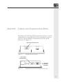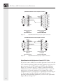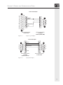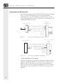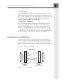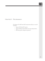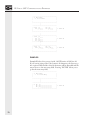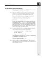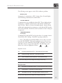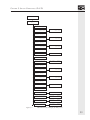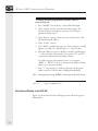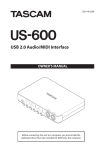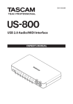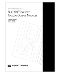
1
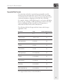
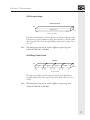
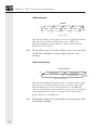
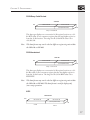
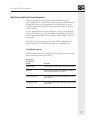
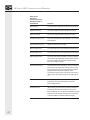
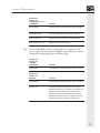
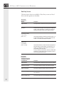
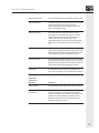
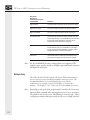
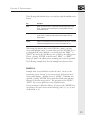
Publication 0300164-01 Rev. A
GE FANUC SNP
Communications Reference
NOTICE
The products and services described in this manual are useful in a wide variety of applications.
Therefore, the user and others responsible for applying the products and services described herein are
responsible for determining their acceptability for each application. While efforts have been made to
provide accurate information within this manual, Spectrum Controls assumes no responsibility for
the accuracy, completeness or usefulness of the information contained herein.
Under no circumstances will Spectrum Controls be responsible or liable for any damages or losses,
including indirect or consequential damages or losses, arising out of either the use of any information
contained within this manual or the use of any product or service referenced herein.
No patent liability is assumed by Spectrum Controls with respect to the use of any of the information, products, circuits, programming or services referenced herein.
The information contained in this manual is subject to change without notice.
CAUTION
Spectrum Controls’ devices contain electronic components which are susceptible to damage from
electrostatic discharge. A static charge can accumulate on the surface of ordinary plastic wrapping or
cushioning material. If any Spectrum Controls’ device must be returned to Spectrum Controls, the
following packaging instruction must be followed:
PREFERRED: Use the original packaging material as supplied by Spectrum Controls. Place
the device inside the conductive plastic bag.
ACCEPTABLE: Wrap the device in some type of antistatic material. Antistatic plastic material
can be identified by its pink color, and can be obtained in sheet or bag form.
UNACCEPTABLE: Do not use ordinary plastic film, foam, or styrene chips (“popcorn” or
“peanuts”). These materials can accumulate charges in excess of 10,000 volts, resulting in
possible damage to the Spectrum Controls electronic device.
Antistatic (metallized plastic) bags can be obtained from the following manufacturers:
3M Company
Static, Inc.
Charles Water
(800-328-1368)
(800-782-8424)
(617-964-8370)
Type 2100 bag
8000 Series bag
CP-303 bag
i
LIMITED WARRANTY
Spectrum Controls warrants that its products are free from defects in material and workmanship
under normal use and service, as described in Spectrum Controls literature covering this product, for
a period of 1 year. Spectrum Controls’ obligations under this warranty are limited to replacing or
repairing, at its option, at its factory or facility, any product which shall, in the applicable period
after shipment, be returned to Spectrum Controls’ facility, transportation charges prepaid, and which
after examination is determined, to the satisfaction of Spectrum Controls, to be thus defective.
This warranty shall not apply to any such equipment which shall have been repaired or altered except
by Spectrum Controls or which shall have been subject to misuse, neglect or accident. In no case
shall Spectrum Controls’ liability exceed the purchase price. The aforementioned provisions do not
extend the original warranty period of any product which has either been repaired or replaced by
Spectrum Controls.
Copyright and Trademark information
SOI, SOI-SPS, and SOI-PRO are trademarks of Spectrum Controls, Inc.
IBM is a registered trademark of International Business Machines Corporation.
MS-DOS is a registered trademark of Microsoft Corporation.
All other trademarks belong to their respective owners.
ii
CONTENTS
PREFACE
...................................................................... 1
Who Should Use this Reference...................................... 1
Related Documents ........................................................ 2
CHAPTER 1: CABLING
AND
COMMUNICATION PORTS ... 3
Uploading and Downloading Application Programs ....... 4
Connecting to the GE Fanuc Series PLC ........................ 8
Outputting Printer Forms (SOI-260 only) ..................... 9
Accepting ASCII Input (SOI-260 only) ........................ 10
CHAPTER 2: PROGRAMMING .......................................... 11
Supported GE Fanuc PLC Registers ............................. 12
Supported Data Formats............................................... 13
Data Display and Entry Screen Parameters................... 19
Multiple Entry.............................................................. 24
GE Fanuc-Specific Configuration Parameters ............... 27
CHAPTER 3: TROUBLESHOOTING ................................... 28
CHAPTER 4: TERMINAL MODE ...................................... 30
“Arcade” Entry of ASCII Characters ............................. 30
Direct ASCII Code Entry (SOI-260 only) .................... 31
iii
CHAPTER 5: SPECIAL OPERATIONS (P-A/D) ............... 32
Point-Access/Display on the SOI-120 ..........................32
Point-Access/Display on the SOI-260 ..........................34
iv
PREFACE
PREFACE
Read this preface to familiarize yourself with the rest of this Reference.
This preface covers:
•
who should use this guide
•
related documents
This Reference covers the information needed to use an SOI-120 or
-260 operator interface product with a GE Fanuc Programmable Logic
Controller. The Reference contains the information you need to install,
program, troubleshoot, and use your SOI.
Please read all the information in this reference before you install or use
your SOI.
Who Should Use this Reference
Use this Reference if you design, install, program, or maintain a control
system that uses a GE Fanuc programmable controllers which support
the SNP protocol.
This reference assumes a full working knowledge of the relevant
programmable controller.
You should have a basic understanding of computer products. If you do
not, contact your local distributor for the proper training before using
these products.
OMRON HOST LINK COMMUNICATIONS REFERENCE
Related Documents
The following table lists related documents that may help you as you
install and use these products:
Publication Number
Title
0300050
SOI-260 Operator Interface User Manual
0300051
SOI-120 Operator Inferface User Manual
0300054
SOI-SPS Programming Software Manual
0300063
Upload/Download Cable For SOI-120 and SOI-260
CHAPTER 1: CABLING
CHAPTER 1:
AND
COMMUNICATION PORTS
CABLING AND COMMUNICATION PORTS
This chapter of the GE Fanuc SNP Communications Reference covers the
cabling needed to use the SOI-120’s RS-232 communications port (see
Figure 1.1) and the SOI-260’s communications port and optional
printer port (see Figure 1.2).
RS-232/485 Communications Port
Figure 1.1
SOI-120 Communications Port.
Optional RS-232
Printer Port (male)
RS-232/485
Communications
Port (female)
Figure 1.2
SOI-260 Communications Port and Optional Printer Port.
3
GE FANUC SNP COMMUNICATIONS REFERENCE
Use the communication ports to...
•
upload or download application programs from a personal
computer
•
connect your SOI-120 or SOI-260 to the programmable
controller
On the SOI-260, you can also use the optional RS-232 printer port to...
•
output Printer Forms to a printer or other serial device, such as a
large ASCII display unit
•
accept data from an ASCII input device (such as a bar code
scanner)
Uploading and Downloading Application Programs
On the SOI-260, you may use either the communications port or the
optional printer port to upload or download application programs from
a personal computer.
On the SOI-120, you must use the communications port.
The following subsections describe the cabling needed.
Upload/Download via Communications Port (RS-232 communications
selected)
Figures 1.3 and 1.4 show the cable pin connections (9-pin to 25-pin
and 9-pin to 9-pin, respectively) when using the SOI-120’s or SOI260’s communications port (RS-232 selected) to upload or download
applications from a personal computer. The figures indicate the required
connections when building your own cable.
4
CHAPTER 1: CABLING
AND
6
7
8
9
COMMUNICATION PORTS
Upload/Download Cable for 25-Pin Computer Connections
(identical to the Spectrum Controls SCC-3 cable)
1
1 2
1
Data Out
2 3
2
Data In
Data In
3 4
3
Data Out
5 4
4 5
4 5
5 6
Signal Ground
3 6
6 7
2 7
7 8
1 8
8 9
25 10
9
Shield
11
12
13
DB-9 Connector (male)
to SOI-120 or SOI-260
Comm. Port
(RS-232 selected)
Figure 1.3
14
15
16
17
18
19
20
21
22
23
24
25
DB-25 Connector (female)
to Computer
Serial Port (COM1, COM2)
Upload/Download cable for 25-pin computer connections.
Upload/Download Cable for 9-Pin Computer Connections
5
4
3
2
1
6
7
8
9
1
2
3
4
5
6
7
8
9
Data In
Data Out
Signal Ground
Shield
DB-9 Connector (male)
to SOI-120 or SOI-260
Comm. Port
(RS-232 selected)
Figure 1.4
Data Out
Data In
1
2
3
4
5
6
7
8
9
1
2
3
4
5
9
8
7
6
DB-9 Connector (female)
to Computer
Serial Port (COM1, COM2)
Upload/Download cable for 9-pin computer connections.
Upload/Download via Optional Printer Port (SOI-260 only)
Figures 1.5 and 1.6 show the cable pin connections (9-pin to 25-pin
and 9-pin to 9-pin, respectively) when using the SOI-260’s optional
printer port to upload or download applications from a personal
computer. The figures indicate the required connections when building
your own cable.
5
GE FANUC SNP COMMUNICATIONS REFERENCE
Upload/Download Cable for 25-Pin Computer Connections
5
4
3
2
1
6
7
8
9
1
2
3
4
5
6
7
8
9
Data In
Data Out
Signal Ground
Shield
DB-9 Connector (male)
to SOI-260
Optional Printer Port
Figure 1.5
Data Out
Data In
1
2
3
4
5
6
7
8
25
1
2
3
4
5
6
7
8
9
10
11
12
13
14
15
16
17
18
19
20
21
22
23
24
25
DB-25 Connector (female)
to Computer
Serial Port (COM1, COM2)
Upload/Download cable for 25-pin computer connections.
Upload/Download Cable for 9-Pin Computer Connections
5
4
3
2
1
6
7
8
9
1
2
3
4
5
6
7
8
9
Data In
Data Out
Signal Ground
Shield
DB-9 Connector (female)
to SOI-260
Optional Printer Port
Figure 1.6
Data In
Data Out
1
2
3
4
5
6
7
8
9
1
2
3
4
5
9
8
7
6
DB-9 Connector (female)
to Computer
Serial Port (COM1, COM2)
Upload/Download cable for 9-pin computer connections.
Upload/Download with the Spectrum Controls SCC-3 Cable
If you don’t want to build your own cable, Spectrum Controls offers the
SCC-3 cable for uploading and downloading application programs. The
pin connections for the SCC-3 cable are identical to those shown in
Figure 1.2. You may use the SCC-3 cable to connect the SOI-120’s
communications port or SOI-260’s communications port or optional
printer port to a personal computer. If your computer has a 9-pin
communications port, you need a 25-to-9 pin adapter, shown in Figure
1.7. If you want to use the SOI-260’s optional printer port for
uploading and downloading applications, you also need a 9-pin female
adapter, shown in Figure 1.8.
6
CHAPTER 1: CABLING
AND
COMMUNICATION PORTS
25-Pin to 9-Pin Adapter
13
12
11
10
9
8
7
6
5
4
3
2
1
14
15
16
17
18
19
20
21
22
23
24
25
1
2
3
4
5
6
7
8
20
1
2
3
4
5
6
7
8
9
Data Out
Data In
Signal Ground
DTR
DB-25 Connector (male)
to SCC-3 Cable
Figure 1.7
1
2
3
4
5
9
8
7
6
DB-9 Connector (female)
to Computer
Serial Port (COM1, COM2)
25-pin to 9-pin adapter.
9-Pin Female Adapter
5
4
3
2
1
6
7
8
9
1
2
3
4
5
6
7
8
9
Data In
Data Out
Signal Ground
Shield
DB-9 Connector (female)
to SOI-260
Optional Printer Port
Figure 1.8
1
2
3
4
5
6
7
8
9
1
2
3
4
5
9
8
7
6
DB-9 Connector (female)
to SCC-3 Cable
9-pin female adapter.
7
GE FANUC SNP COMMUNICATIONS REFERENCE
Connecting to the GE Fanuc PLC
The SOI may be connected to the GE Fanuc PLC via the programming
port or one of the SNP capable ports in an optional GE Fanuc
Communications Coprocessor Module as shown in Figures 1.9 and
1.10. (Contact Spectrum Controls for information on interfacing to the
CMM using Modbus protocol.)
GE Fanuc
Programming Port
DB15
SOI-120 / SOI-260
DB9
120Ω
***
Figure 1.9
1
2
3
4
9
5
RD
RD
SD
SD
(A’)
(B’)
(A)
(B)
Differential Receive Data
Differential Receive Data
Differential Send Data
Differential Send Data
** Cable Shield
Signal Ground
Resistor Termination
RTS (A)
CTS (A’)
RTS (B’)
CTS (B)
10
11
12
13
1
7
9
6
15
14
8
Connecting to the PLC Programming Port 2
SOI-120/SOI-260
DB9
1
2
3
4
9
5
Figure 1.10
Series 90-30 CMM 311
Port 2
DB25
RD (A’) Differential Receive Data
RD (B’) Differential Receive Data
SD (A) Differential Send Data
SD (B) Differential Send Data
** Cable Shield
Signal Ground
* Resistor Termination
RTS (A)
CTS (A’)
RTS (B)
CTS (B)
13
25
9
21
1
7
24
10
11
22
23
Connecting to the CMM Port 2 (RS485/422)
* Series 90-30 Resistor Termination:
The PLC communnication port Receive Data differential pair must be
terminated as indiated if the PLC is either the first or last drop on the
SNP bus. This is always the case in a point-to-point configuration.
However, PLCs may be connected as multiple drops. Do not connect
the termination resistor if the PLC is not the first or last drop on the
SNP bus.
8
CHAPTER 1: CABLING
AND
COMMUNICATION PORTS
** Shield Ground:
The shield must be grounded at the first drop on the SNP bus. If the
SOI is the first drop on the bus, connect the SOI communication port
pins 5 and 9. If the PLC is the first drop on the bus, connect pins 1 and
7 on the PLC port. Do not connect the shield to gorund on more
than one unit (SOI or PLC) on the SNP bus.
*** SOI Resistor Termination:
The SOI communication port Receive Data differential pair must be
terminated as indicated if the SOI is either the first or last drop on the
SNP bus. This is always the case in a point-to-point configuration.
However, multiple PLCs may be connected to the SNP bus. Do not
connect the termination resistor if the SOI is not the first or last drop
on the SNP bus. The SOI will only connect to and communicate with
one PLC regardless of how many are attached to the SNP bus.
Outputting Printer Forms (SOI-260 only)
You can use the SOI-260’s optional printer port to output Printer
Forms to a printer or other serial device, such as a large ASCII display
unit. Printer forms are created in the SOI-SPS programming software
and may include production reports, alarm messages, instructional text,
etc.
Figure 1.11 illustrates the cabling needed.
Printer Port Cable
5
4
3
2
1
6
7
8
9
1
2
3
4
5
6
7
8
9
Data In
Data Out
Signal Ground
Req. to Send
Clear to Send
Shield
DB-9 Connector (female)
to SOI-260
Printer Port
Figure 1.11
Req. to Send
Clear to Send
1
2
3
4
5
6
7
8
9
1
2
3
4
5
9
8
7
6
DB-9 Connector (male)
to Printer
or other serial device
Printer port cable.
9
GE FANUC SNP COMMUNICATIONS REFERENCE
Accepting ASCII Input (SOI-260 only)
The SOI-260’s optional RS-232 printer port may also be used to accept
ASCII data from a variety of devices, including bar code scanners.
When using a scanner to read a bar code, the ASCII data is entered
directly from the device into a standard data entry screen (created using
the SOI-SPS programming software) on the SOI-260.
Note: If the SOI-260 recieves an odd number of characters from the scanner,
the SOI-260 adds a Null character to create an even byte count. This
facilitates word writes to the controller.
If keypad entry is enabled, the operator may also use the 0–9 and
decimal point keys to enter numeric data into the data entry field. The
SOI-260 writes data to the controller when any of the following occurs:
•
the SOI-260 receives an ASCII carriage return character
•
the operator presses the SOI-260’s RETURN key
•
the SOI-260 receives the maximum number of characters
For example, an operator can manually enter 2 characters and then scan
a bar code containing 8 characters, with the last character being an
ASCII carriage return. The SOI-260 then writes all 10 characters to the
controller and moves to the next entry field.
10
CHAPTER 2: PROGRAMMING
CHAPTER 2:
PROGRAMMING
This chapter of the GE Fanuc SNP Communications Reference covers the
following:
•
supported GE Fanuc PLC registers
•
supported SOI-120 and SOI-260 screen types and parameters
•
GE Fanuc-specific configuration parameters
11
GE FANUC SNP COMMUNICATIONS REFERENCE
Supported GE Fanuc PLC Registers
The SOI-120 and SOI-260 support the following registers:
Type Name
Size
1
R
Registers
16 bit word
Read/Write
1-16,384
AI
Analog Inputs
16 bit word
Read/Write
1-8,192
AQ
Analog Outputs
16 bit word
Read/Write
1-8,192
I
Discrete Inputs
bit
byte
Read/Write
1-12,288
1-1,536
Q
Discrete Outputs
bit
byte
Read/Write
1-12,288
1-1,536
T
Discrete Temporaries
bit
byte
Read/Write
1-256
1-32
M
Discrete Internals
bit
byte
Read/Write
1-12,288
1-1,536
SA
Discretes
bit
byte
Read/Write
1-128
1-16
SB
Discretes
bit
byte
Read/Write
1-128
1-16
SC
Discretes
bit
byte
Read/Write
1-128
1-16
S
Discretes
bit
byte
Read/Write
1-128
1-16
G
Genius Global
Data
bit
byte
Read/Write
1-7,680
1-960
1
Access
1
Range
Your PLC may not support all the access methods and addresses listed
here. Attempting to acheive access not allowed by the PLC or to an
address not supported by the PLC will result in a communications fault
while using the SOI.
12
CHAPTER 2: PROGRAMMING
Supported Data Formats
The data format selected for a particular programmable controller
memory location must reflect the correct format for the data actually
stored in that location. This is the only way you can ensure that correct,
consistent information is displayed on the SOI-120 or SOI-260.
For example, selecting a 16-Bit Hex format for one location will display
data in one way. Selecting a 16-Bit Signed Integer format for the same
location will display the data in another way. It is important to
understand each data format and its characteristics.
The following table lists all supported data formats and the ranges
applicable to each:
Data Format
Range
Scalable to Engineering Units
Bit
0, 1
No
16-bit signed integer
-32,768 to +32,767
Yes
16-bit unsigned integer
0 to +65,535
Yes
16-bit BCD
0 to 9,999
Yes
16-bit hexadecimal
0 to FFFF
No
32-bit unsigned integer
0 to +4,294,967,295
No
32-bit BCD
0 to +99,999,999
No
32-bit hexadecimal
0 to FFFF FFFF
No
ASCII display
0 to 20 characters
No
ASCII input (SOI-260 only)
0 to 32 characters
No
The supported data formats are described below.
13
GE FANUC SNP COMMUNICATIONS REFERENCE
Bit
Bit Data
MSB
15
14 13 12 11 10
9
8
7
6
5
4
3
2
1
0
LSB
16 individual bits
(One 16-bit location)
The programmable controller stores a binary (0 or 1) status for a bit
location. The SOI will read a programmable controller bit location and
determine whether the operational status of the bit is ON (1) or OFF
(0). You can customize the text to be displayed on the screen of the
SOI-120 or SOI-260 for either state of a specified bit. This text can be
up to twenty characters.
For example, the OFF (0) state of a bit might display “Pump is OFF,”
and the ON (1) state “Pump is ON.” SOI-SPS allocates enough screen
characters for the longest of the two text strings. In this example, 12
characters would be allocated to display “Pump is OFF.”
Note: The fewer characters used, the less memory is required. In the example
above, displaying "OFF" (given the appropriate context) conveys the
same information in 3 characters as "Pump is OFF" does with 11
characters.
16-Bit Signed Integer
16-Bit Signed Integer
MSB
15-Bit Data Field
Bit 15
(sign bit)
LSB
Bit 0
Range = -32768 to +32767
This data type displays a 16-bit register as a signed Integer (two’s
complement) value. The 16th bit of the register is the sign bit and is set
(1) for a negative and cleared (0) for a positive number. The 16-bit
signed integer values have a range of -32768 to +32767.
Note: This data format may be scaled within the SOI-120 or SOI-260 to
different engineering units.
14
CHAPTER 2: PROGRAMMING
16-Bit Unsigned Integer
16-Bit Unsigned Integer
MSB
16-Bit Data Field
LSB
Bit 15
Bit 0
Range = 0 to +65535
This data format displays a 16-bit register as an Unsigned Integer value.
It represents a positive number by using the 16th bit as a data bit rather
than a sign bit. The 16-bit Unsigned Integer values have a range of 0 to
+65,535.
Note: This data format may also be scaled to different engineering units
within the SOI-120 or SOI-260.
16-Bit Binary Coded Decimal
16-Bit BCD
MSB
Digit 4
Bit
15
Digit 3
Bit
12
Bit
11
Digit 2
Bit
8
Bit
7
Digit 1
Bit
4
Bit
3
LSB
Bit
0
Range = 0 to 9999
This data type displays a 16-bit register location as a 4-digit Binary
Coded Decimal value. The range for the 16 bit BCD selection is 0 to
+9999.
Note: This data format may also be scaled to different engineering units
within the SOI-120 or SOI-260.
15
GE FANUC SNP COMMUNICATIONS REFERENCE
16-Bit Hexadecimal
16-Bit HEX
MSB
Digit 4
Bit
15
Digit 3
Bit
12
Bit
11
Digit 2
Bit
8
Bit
7
Digit 1
Bit
4
Bit
3
Bit
0
LSB
Range = 0 to FFFF
This data type displays a 16-bit register location as a 4-digit hexadecimal
value. The range for the 16-bit Hex format is 0 to +FFFF. The
Hexadecimal number system is defined as a base of 16 (0-9 and the
characters A, B, C, D, E, F).
Note: This data format may not be scaled to different engineering units within
the SOI-120 or SOI-260. It is used for display-only (non-entry)
operations.
32-Bit Unsigned Integer
32-Bit Unsigned Integer
MSB
16-Bit Location #1
16-Bit Location #2
(next sequential location)
Range = 0 to 4,294,967,295
This data format displays data located in two consecutive 16-bit register
locations as a 32-bit Unsigned Integer. It uses a memory register plus
the next higher register to form the 32-bit location. The High data
value is stored in the first register and the Low data value is stored in the
next sequential register location. The range for the 32-bit unsigned
Integer value is 0 to +4,294,967,295.
Note: This data format may not be scaled to different engineering units within
the SOI-120 or SOI-260.
16
LSB
CHAPTER 2: PROGRAMMING
32-Bit Binary Coded Decimal
32-Bit BCD
MSB
16-Bit Location #1
16-Bit Location #2
(next sequential location)
LSB
Range = 0 to 99,999,999
This data type displays two consecutive 16-bit register locations as a 32bit BCD value. It uses a memory register plus the next higher register to
form the 32 bit location. The range for the 32 bit BCD value is 0 to
+99,999,999.
Note: This data format may not be scaled to different engineering units within
the SOI-120 or SOI-260.
32-Bit Hexadecimal
32-Bit HEX
MSB
16-Bit Location #1
16-Bit Location #2
(next sequential location)
LSB
Range = 0 to FFFF FFFF
This data type displays two consecutive 16-bit register locations as a 32bit Hex value. It uses a memory register plus the next higher register to
form the 32-bit location. The range for the 32-bit HEX value is 0 to
FFFF FFFF.
Note: This data format may not be scaled to different engineering units within
the SOI-120 or SOI-260. This data format is used for display-only
(non-entry) operations.
ASCII
ASCII Data Field
MSB
8-Bit Location #1
8-Bit Location #2
(next sequential location)
CHR #1
LSB
CHR #2
17
GE FANUC SNP COMMUNICATIONS REFERENCE
Each 16-bit location may contain two ASCII characters (1 byte each).
By default, the most significant byte of the base address stores the first
character, the least significant byte stores the second character, the first
byte of the next sequential location stores the third character, and so on.
The data held in this range of address locations is expected to be in
ASCII data format.
Note: The ASCII data format is very useful for programmable controller
applications reading ASCII data from bar code readers or data
collection terminals.
Note: This data format may not be scaled to different engineering units within
the SOI-120 or SOI-260.
18
CHAPTER 2: PROGRAMMING
Data Display and Entry Screen Parameters
When programming Data Display and Data Entry fields and
positioning them on an SOI-120 or SOI-260 screen, each field must be
defined according to its programmable controller memory location
(address), data format, and other data parameters specific to the data
format selected.
You are prompted for the register definitions at the Control Window.
Each register definition is somewhat different, depending on the data
format selected and whether the data field is a Data Display or Data
Entry field.
The tables in the following two subsections list the applicable data
formats and the Control Window prompts associated with each.
Data Display Screens
The data format selections available for Data Display screens are listed
below and their parameters described.
Display Screen
Parameter for:
Bit Data
Description
Register Number
The programmable controller data location operand and address.
Bit Number
The Bit number if the register number designates a multiple bit
location (a 16 bit data address, for example).
Text when Bit is OFF (0)
The 20 character text description to be displayed when the bit is in
an OFF (0) state
Text when Bit is ON (1)
The 20 character text description to be displayed when the bit is in
an ON (1) state.
19
GE FANUC SNP COMMUNICATIONS REFERENCE
20
Display Screen
Parameter for:
16-Bit Unsigned Integer,
16-Bit Signed Integer &
16-Bit BCD Data
Description
Register Number
The programmable controller data location operand and address.
Digits Right of Decimal
The number of digits to be placed to the right of the decimal.
Digits Left of Decimal
The number of digits to be placed to the left of the decimal.
Leave Place for Sign (Y or N)
Leave a one character place for the polarity sign (+ or -) when the
data is displayed.
Show Leading Zeros (Y or N)
Display any zeros to the left of the data.
Minimum Register Value
The minimum data value of the programmable controller location.
Maximum Register Value
The maximum data value of the programmable controller location.
Minimum Displayed Value
The minimum data value to be displayed. This value is displayed
when the data in the programmable controller location is equal to
the minimum register value. See Maximum Displayed Value,
below, for a description of scaling.
Maximum Displayed Value
The maximum data value to be displayed. This value is displayed
when the data in the programmable controller location is equal to
the maximum register value. The range defined by the Minimum
Displayed Value and the Maximum Displayed Value is
proportionally scaled to the range of the minimum and maximum
register values. If both ranges are equal then the scaling ratio is
1:1.
Minimum Bar Value
(Bar Graph Only) The minimum value of data to be displayed in
the Bar Graph. This value must be greater or equal to the
Minimum Displayed Value.
Maximum Bar Value
(Bar Graph Only) The maximum value of data to be displayed in
the Bar Graph. This value must be less than or equal to the
Maximum Displayed Value. The Minimum and Maximum bar graph
values may be used to display a particular range or window of an
overall range (Minimum and Maximum Displayed Values).
CHAPTER 2: PROGRAMMING
Display Screen
Parameter for:
32-Bit Unsigned Integer &
32-Bit BCD Data
Description
Register Number
The programmable controller data location operand and address.
Digits Right of Decimal
The number of digits to be placed to the right of the decimal.
Digits Left of Decimal
The number of digits to be placed to the left of the decimal.
Show Leading Zeros (Y or N)
Display any zeros to the left of the data.
Note: For the 32-Bit BCD selections, scaling of data is not supported. The
selected register number and the next higher sequential register number
identify the locations defining the 32 bit data value.
Display Screen
Parameter for:
16 -Bit HEX,
32-Bit HEX Data
Description
Register Number
The programmable controller data location operand and address.
Display Screen
Parameter for:
ASCII Data:
Description
Register Number
The programmable controller data location operand and address.
Character Count
The number of characters (2 characters for each 16 bit data
location) to be displayed, up to a maximum of 20 characters. The
initial byte of the location identified by the register number is
displayed first, then the second byte, the first byte of the next
higher sequential location, and so on. To display 20 characters, a
sequential block of ten 16 bit locations is read by the SOI.
21
GE FANUC SNP COMMUNICATIONS REFERENCE
Data Entry Screens
The data format selections available for Data Entry screens are listed
below and their parameters described.
Entry Screen
Parameter for:
Bit Data
Description
Register Number
The programmable controller data location operand and address.
Bit Number
The Bit number if the register number designates a multiple bit
location (a 16 bit data address, for example). This selection is
irrelevant if the register number refers to a Bit type address.
Input Data by Pressing
‘1’/’0' or ‘Y’/’N’ ?
(Enter 1 or Y)
This parameter determines whether the operator will enter 1 or Y
to set the defined bit location. If 1 is entered, 0 will clear the bit
location. If Y is entered, N will clear the bit location.
Default Value ?
Z = No Default
(Enter 1,0,Y,N,Z)
22
This parameter defines the default value that is displayed at the
data entry position of the SOI display. If a default value of Y is
entered, a Y is displayed, and the operator is only required to
press ENTER to set the bit location.
An entry of Z defines no default value. If there is no default value
programmed, and the operator presses the ENTER, no data is
sent to the programmable controller.
Entry Screen
Parameter for:
16-Bit Unsigned Integer,
16-Bit Signed Integer &
16-Bit BCD Data
Description
Register Number
The programmable controller data location operand and address.
Digits Right of Decimal
The number of digits to be placed to the right of the decimal.
Digits Left of Decimal
The number of digits to be placed to the left of the decimal.
Leave Place for Sign (Y or N)
Leave a one character place for the polarity sign (+ or -) when the
data is displayed.
Minimum Register Value
The minimum data value of the programmable controller location.
CHAPTER 2: PROGRAMMING
Maximum Register Value
The maximum data value of the programmable controller location.
Minimum Entry Value
The minimum data value to be entered. When this value is entered
the minimum register value is entered to the defined
programmable controller location. See Maximum Entry Value,
below, for a description of scaling.
Maximum Entry Value
The maximum data value to be entered. When this value is
entered the maximum register value is entered to the defined
programmable controller location. The range defined by the
minimum entry value and the maximum entry value is
proportionally scaled to the range of the minimum and maximum
register values. If both ranges are equal then the scaling ratio is
1:1.
Low User Input Limit
The minimum entry value that an operator may enter. This value
must be within the minimum and maximum entry values. If a value
lower than this limit is entered the SOI will display an “Input Error”
screen displaying the minimum and maximum entry limits.
High User Input Limit
The maximum entry value that an operator may enter. This value
must be within the minimum and maximum entry values. If a value
higher than this limit is entered the SOI will display an “Input Error”
screen displaying the minimum and maximum entry limits.
Default Value
This parameter defines a default value that is displayed at the
entry location of the display. An entry of Z defines no default value.
Entry Screen
Parameter for:
ASCII Data
Description
Register Number
The programmable controller data location operand and address.
Character Count
The number of characters (2 characters for each 16 bit data
location) to be displayed, up to a maximum of 32 characters. The
initial byte of the location identified by the register number is
displayed first, then the second byte, the first byte of the next
higher sequential location, and so on.
23
GE FANUC SNP COMMUNICATIONS REFERENCE
Entry Screen
Parameter for:
32-Bit Unsigned Integer &
32-Bit BCD Data
Description
Register Number
The programmable controller data location operand and address.
Digits Right of Decimal
The number of digits to be placed to the right of the decimal.
Digits Left of Decimal
The number of digits to be placed to the left of the decimal.
Low User Input Limit
The minimum entry value that an operator may enter. This value
must be within the range of 0 to +99,999,999. If a value lower than
this is entered, the SOI will display an “Input Error” screen
displaying the minimum and maximum entry limits.
High User Input Limit
The maximum entry value that an operator may enter. This value
must be within the range of 0 to +99,999,999. If a value higher
than this is entered, the SOI will display an “Input Error” screen
displaying the minimum and maximum entry limits.
Default Value
This parameter defines a default value that is displayed at the
entry location of the display. An entry of Z defines no default.
Note: For the 32-Bit BCD selections, scaling of data is not supported. The
defined register number and the next higher sequential number locations
will define the data value.
Multiple Entry
The SOI-120 and SOI-260 with the GE Fanuc SNP communications
protocol can now accept and display multiple entries per screen. The
recommended limits are 4 entries/displays per screen (in any
combination: for example 3 entries & 1 display or 2 entries & 2
displays). The display is “live” unless you are in the middle of an entry.
Note: Depending on the speed of the programmable controller, the cursor may
appear to flash erratically when moving from screen to screen or between
entry fields on the current screen. This flashing is consmetic only. This is
a temporary condition which goes away once the screen is fully refreshed.
24
CHAPTER 2: PROGRAMMING
The following table decribes how to use the keys with the multiple entry
feature.
Key
Description
NEXT
Moves you to the next screen. Cursor will be at the first (top left) entry of each
screen. If at end of a series of linked screens, pressing “NEXT” moves the
cursor between entries.
PREV
Moves you up the list of linked screens. Cursor will be at the first (top left) entry
of each screen. If at start of a series of linked screens, “PREV” moves you
between entries.
ENTER
Allows you to send data and move to next entry within an entry screen. If no data
is entered, pressing ENTER moves you from one entry field to the next.
When using the function keys on the SOI-120 to jump to an entry
screen with multiple entries, you must either press the “ENTER” key to
go through all the entries defined, or your must press the “PREV’” or
“NEXT” key, before the SOI allows you to go back to the calling screen.
That is, pressing “ENTER” at the last entry, “PREV”, or “NEXT”
brings you back to the calling screen (assuming auto-return is specified).
The following examples show how the multiple entry feature works:
EXAMPLE A
Example A has 4 screens linked one after the other. Screen 1 is the
main menu screen. Screens 2–4 are entry screens. Each screen has 4
entries and 0 displays. Defaults are set to “NONE”. If defaults were
specified, pressing “ENTER” always sends the default value and then
advances to the next entry position. The user must use the “PREV”/
”NEXT” key to move up/down a series of linked screens.
Cursor movement is defined as follows: If you press the “ENTER” key
several times, the cursor moves in the following order: (1), (2), (3) and
(4) then back to (1).
25
GE FANUC SNP COMMUNICATIONS REFERENCE
——————————————————————————————————————————
| 1) Main Screen
|
| 1. Go to Screen 2
|
|
|
|
|
|————————————————————————————————————————|
|
|
——————————————————————————————————————————
| 2) R0: _(1)_____
R1: _(2)_____
|
|
R2: _(3)_____
R3: _(4)_____
| <— Screen #2
|
|
|
|
|————————————————————————————————————————|
|
|
——————————————————————————————————————————
| 3) R4: _(1)_____
|
|
R5: _(2)_____
| <— Screen #3
|
R6: _(3)_____
|
|
R7: _(4)_____
|
|————————————————————————————————————————|
|
|
——————————————————————————————————————————
| 4) R8: _(1)_____
R9: _(2)_____
|
|
R10: _(3)_____
R11: _(4)_____
| <— Screen #4
|
|
|
|
|————————————————————————————————————————|
EXAMPLE B
Example B below show screen 2 with 3 ASCII entries of field size 10.
If you scan in (using a Bar Code Scanner) 20 characters, the first ten go
into register DM0 and the other 10 characters will be discarded and the
cursor moves to the next entry field. Pressing “ENTER” allows you to
go the the next entry field.
——————————————————————————————————————————
| 1) Main Screen
|
| 1. Go to ASCII Entry
|
|
|
|
|
|————————————————————————————————————————|
|
|
|
——————————————————————————————————————————
| 2) R0: _(1)____________________
|
|
R1: _(2)____________________
| <— Screen #2
|
R2: _(3)____________________
|
|
|
|————————————————————————————————————————|
26
CHAPTER 2: PROGRAMMING
GE Fanuc-Specific Configuration Parameters
This section describes the GE Fanuc-specific PLC hardware parameters
that the SOI-SPS programming software supports.
Note: Refer to the SOI-SPS programming software manual for complete
details on programming and additional information regarding the
parameters accessible from the SOI Configuration Data menu.
Select the PLC Hardware Parameters menu option from the SOI
Configuration Data menu to modify the PLC Address,
Communications Port Setup, or Advisor Update Rate.
PLC CPU ID:
<default = blank>
The PLC CPU ID may be blank or any combination from one to six
ASCII characters of the ‘0’ - ‘9’ or ‘A’ - ‘F’ upper case only. If blank,
the SOI will assume it is in a point-to-point connection and broadcast
with a NULL CPU ID. The CPU ID must match the CPU ID of the
PLC with which the SOI is to connect. The PLC must be configured
with the GE Fanuc PLC programming software.
Note: Do not use a blank CPU ID in a multidrop configuration. If you do,
communications on all units on the bus is likely to fail.
Communications Baud Rate:
<default = 19,200>
Data Bits: <default = 8>
Parity
<default = odd>
The communications must match those in the PLC as configured with
the GE Fanuc PLC programming software.
The default Advisor Update Rate is: 2.00.
Note: SPS and the SOI do not support PLC passwords. The PLC must be
operating at an access level three (3) or higher with no password for the
SOI to establish a connection.
27
GE FANUC SNP COMMUNICATIONS REFERENCE
CHAPTER 3:
TROUBLESHOOTING
This chapter of the GE Fanuc SNP Communications Reference provides
solutions to possible problems with the SOI-120 and SOI-260 and their
use with the GE Fanuc SNP communications protocol.
Typically, any problems that occur involve communications between
the SOI-120 or SOI-260 and the PLC. The communications software
used to communicate with the PLC has passed critical compliance tests,
usually eliminating the software as a possible source of a problem.
The only other possible sources are the cabling and the communication
port parameters involved (baud rate, etc.). The communication parameters must be identical for both the SOI-120 or SOI-260 and the PLC.
The cabling and the communications port parameters are always the
first things to check.
Note: You can check the communications port parameters either from the SOI
(see “Chapter 4: Special Operations (P-A/D)”) or from the SOI-SPS
programming software (see “Chapter 2: Programming”).
If the cabling and communications parameters are correct, put the SOI120 or SOI-260 in Self-Test mode to rule out any non-functioning
features of the SOI.
Note: Refer to the SOI-260 User’s Manual for detailed information about the
Self-Test Mode.
28
CHAPTER 3: TROUBLESHOOTING
The following screens appear on the SOI to indicate a problem:
Establishing Comm
Attempting to communicate to PLC. Action: None. Normal display
when initiating communications with the PLC.
* <PLC ERR MJ/MN:0000>
Communications not established with the PLC. This is displayed after
attempting to establish communications with the PLC and fails after
three (3) tries). (Refer to footnote for further details.) Action: Check
cabling and communications parameters to verify that the PLC matches
those of the SOI-200. Perform the Self-Test function if the Comm port
is suspected.
*
COMM ERROR MJ/MN:0000
Press Any Key
Communication with the PLC was lost after three (3) attempts. Action:
Check SOI-to-PLC cabling. Check PLC operating conditions.
* = Note: The SOI reports the Major/Minor errors codes as received
from the GE SNP PLC. If the major and minor error codes are nonzero the error code is defined by the GE SNP. Otherwise, if zero, the
SOI did not detect a response from the PLC. The PLC Major and
00
00
Minor error codes are displayed as follows:
Major
Minor
Major Error Codes:
00h
No response detected from the PLC. Check cabling and comm settings.
02h
Insufficient Privilege to access PLC. Check minor error code.
05h
The PLC detected a Service Request Error. Check minor error code.
Any other Check cabling and comm settings before calling your service rep.
Minor Error Codes:
FEh
No privilege for the attempted operation. The SOi requires access level 3 or higher
F5h
Invalid password. The SOI does not support passwords.
F9h
Task address out of range. Verify register address is valid for your CPU
Any other Check cabling and comm settings before calling your service rep.
29
GE FANUC SNP COMMUNICATIONS REFERENCE
CHAPTER 4:
TERMINAL MODE
Read this chapter of the GE Fanuc SNP Communications Reference to
become familiar with the SOI-120’s and SOI-260’s Terminal Mode of
operation. This chapter covers:
•
“arcade” entry of ASCII characters
•
direct ASCII code entry (SOI-260 only)
In terminal mode, the SOI operates as a simple terminal: each key
pressed on the SOI’s keypad causes a character to be sent out the SOI’s
communications port. Displayable ASCII characters sent into its
communications port are displayed on the SOI’s screen.
“Arcade” Entry of ASCII Characters
The arcade entry method uses the PREV/NEXT keys to scroll through a
set of ASCII characters.
If a character was selected via PREV/NEXT but not entered via
ENTER and some other key is pressed, the new key press overrides the
Arcade entry.
The following character set is provided:
‘ ABCDEFGHIJKLMNOPQRSTUVWXYZ=#?*:%/,$’
The above set includes a space, uppercase A through Z, the equal sign,
the pound sign, the question mark, the asterisk, the colon, the percent
sign, the forward slash, the comma, and the dollar sign.
30
CHAPTER 4: TERMINAL MODE
Direct ASCII Code Entry (SOI-260 only)
The Direct ASCII code entry method allows the user to press the EXP
key followed by a decimal value from 32 through 254 to enter an ASCII
code directly.
31
GE FANUC SNP COMMUNICATIONS REFERENCE
CHAPTER 5:
SPECIAL OPERATIONS (P-A/D)
After pressing “MODE” (the mode key) on the SOI-120 or “F” (the
function key) on the SOI-260, one of the menu items is labelled “Special”. This item provides access to the Point-Access/Display (P-A/D)
feature.
The P-A/D feature gives you access to all unrestricted programmable
controller addresses. With this access, addresses may be displayed and/or
modified. This feature is extremely useful in start-up or debugging
sessions of programs or regular programmable controller operations.
!
CAUTION: The Point-Access/Display feature is a powerful
tool. Its access should be restricted solely to authorized
personnel. When using this feature, it is possible to change
programmable controller data that may alter critical
process control operations.
Note: After pressing “MODE” (SOI-120) or “F” (SOI-260), a Special
Security Screen may be displayed (it has to be created with the SOI-SPS
Programming Software). You must enter one of the three programmed
security codes to continue to the Special Operations menu screen.
Point-Access/Display on the SOI-120
Figure 5.1 shows the Point-Access/Display screens and the key presses
linking them:
32
CHAPTER 5: SPECIAL OPERATIONS (P-A/D)
ID:
GE SNP ID
Select data type
I
BIT
I 00001
Status: OFF (0)
I 00001 Decimal Hex
00000 0000
I
00001
0000
Binary
0000
Q 00001
Status: OFF (0)
Q 00001 Decimal Hex
00000 0000
Q
00001
Binary
0000 0000
T 00001
Status: OFF (0)
T 00001 Decimal Hex
0000 0000
T
00001
Binary
0000 0000
M
00001
Binary
0000 0000
M 00001
Status: OFF (0)
M 00001 Decimal Hex
00000 0000
SA 00001
Status: OFF (0)
SA 00001 Decimal Hex
00000 0000
SA
00001
Binary
0000 0000
SB 00001
Status: OFF (0)
SB
00001 Decimal Hex
00000 0000
SB 00001
Binary
0000 0000
SC
Binary
0000 0000
SC 00001
Status: OFF (0)
SC
00001 Decimal Hex
00000 0000
00001
S 00001
Status: OFF (0)
S 00001 Decimal Hex
00000 0000
S
00001
Binary
0000 0000
G 00001
Status: OFF (0)
G 00001 Decimal Hex
00000 0000
00001 Binary
0000 0000
AI 00001 Decimal Hex
00000 0000
AI 00001
Binary
0000 0000 0000 0000
AQ 00001 Decimal Hex
00000 0000
AQ 00001
Binary
0000 0000 0000 0000
R 00001 Decimal Hex
00000 0000
Figure 5.1
G
R 00001
Binary
0000 0000 0000 0000
SOI-120 Point-Access/Display (P-A/D) screens
33
GE FANUC SNP COMMUNICATIONS REFERENCE
To display or modify programmable controller addresses
from the SOI-120:
1. Press “MODE” (the mode key) on the SOI-120 keypad.
2. Select “Special” (item 3) from the menu that appears. If a
Special Security Screen appears, enter any one of the programmed security codes.
3. Select “Bypass” (item 0), unless you want to Edit (item 1) the
GE Fanuc network address.
4. Select “P-A/D” (item 1).
5. Press “NEXT” until the data type you want to display or modify
appears (see Table 5.1), and then press “↵” (the enter key).
6. Enter the address you want to display or modify, and then press
“↵” (the enter key). Alternatively, you can press “F1” and “F2”
to decrement and increment the address shown.
For 16-bit registers with read/write access, you can press
“PREV” or “NEXT” to move you between the address and data
fields so you can enter new data.
7. Press “↵” (the enter key) to load new data into the programmable controller. This new data is displayed immediately.
Note: At any point, pressing “MENU” returns you to the main menu.
Table 5.1
Supported OMRON registers.
Point-Access/Display on the SOI-260
Figure 5.2 shows the Point-Access/Display screens and the key presses
linking them:
34
CHAPTER 5: SPECIAL OPERATIONS (P-A/D)
GE SNP ID
ID:
Input ID # then
Press “ENTER”
Select data type:
I
BIT
“NEXT” to change
“ENTER” to select
I 00001
Status: OFF (0)
“ENTER“ to change
Point# Decimal Hex
I 00001 00000 0000
15.... Binary ....0
0000 0000
Q 00001
Status: OFF (0)
“ENTER” to change
Point# Decimal Hex
Q 00001 00000 0000
15.... Binary ....0
0000 0000
T 00001
Status: OFF (0)
“ENTER” to Change
Point# Decimal Hex
T 00001 00000 0000
15.... Binary ....0
0000 0000
M 00001
Status: OFF (0)
“ENTER” to change
Point# Decimal Hex
M 00001 0000 0000
15.... Binary ....0
0000 0000
SA 00001
Status: OFF (0)
“ENTER” to change
Point# Decimal Hex
SA 00001 0000 0000
15.... Binary ....0
0000 0000
SB 00001
Status: OFF (0)
“ENTER” to change
Point# Decimal Hex
SB 00001 0000 0000
15.... Binary ....0
0000 0000
SC 00001
Status: OFF (0)
“ENTER” to change
Point# Decimal Hex
SC 00001 0000 0000
15.... Binary ....0
0000 0000
S 00001
Status: OFF (0)
Point# Decimal Hex
S 00001 0000 0000
15.... Binary ....0
0000 0000
G 00001
Status: OFF (0)
“ENTER” to change
Point# Decimal Hex
G 00001 0000 0000
15.... Binary ....0
0000 0000
Point# Decimal Hex
AI 00001 0000 0000
15.... Binary ....0
0000 0000 0000 0000
Point# Decimal Hex
AQ 00001 0000 0000
15.... Binary ....0
0000 0000 0000 0000
Point# Decimal Hex
R 00001 0000 0000
15.... Binary ....0
0000 0000 0000 0000
Figure 5.2
SOI-260 Point-Access/Display (P-A/D) screens
35
GE FANUC SNP COMMUNICATIONS REFERENCE
To display or modify programmable controller addresses
from the SOI-260:
1. Press “F” (the function key) on the SOI-260 keypad.
2. Select “Special” (item 5) from the menu that appears. If a
Special Security Screen appears, enter any one of the programmed security codes.
3. Select “Bypass” (press “N”), unless you want to Edit (press “Y”)
the GE Fanuc network address.
4. Press “1” to use the P-A/D function.
5. Press “PREV” or “NEXT” until the file type you want to display
or modify appears (see Table 5.1), and press “↵” (the enter key).
6. Enter the address you want to display or modify, and then press
“↵” (the enter key). Alternatively, you can press “N” or “Y” to
decrement and increment the address shown.
For 16-bit registers with read/write access, you can press
“PREV” or “NEXT” to move you between the address and data
fields so you can enter new data.
7. Press “↵” (the enter key) to load the new data into the programmable controller. The new data that was loaded into the programmable controller is immediately displayed.
Note: At any point, pressing “MAIN MENU” returns you to the main
menu.
36
CHAPTER 5: SPECIAL OPERATIONS (P-A/D)
APPENDIX A: CONFIGURATION CHANGES
This appendix is intended to inform the user that the GE SNP time
sync format differs from that in the core user’s manual and uses the
format indicated below. The time sync uses the format below for both
the Time Sync Read and Time Sync Write.
Register
Number
Utilization by the SOI
Example
1
R101
Year
2
R102
Month
3
R103
Day
4
R104
Hour
5
R105
Minutes
6
R106
Seconds
In the example either the time sync read or time sync write register is
defined to be R101. From that register the year is read. The following
consecutive registers (increasing by address) will read the Month, Day,
Hour, Minutes and Seconds in that order.
37
GE FANUC SNP COMMUNICATIONS REFERENCE
38
CHAPTER 5: SPECIAL OPERATIONS (P-A/D)
39
Copyright © 1997 Spectrum Controls Inc. All rights reserved.
Specifications subject to change without notice. Printed in USA.
Publication 0300164-01 Rev. A September 1997
U.S.A. Headquarters
Spectrum Controls, Inc.
P.O. Box 5533, Bellevue, WA 98006
Fax: (425) 641-9473 • Tel: (425) 746-9481
Midwestern/Northeastern U.S.A. Sales Office
Spectrum Controls, Inc.
48945 Van Dyke, Suite 4B, Utica, MI 48317
Fax: (810) 731-2715 • Tel: (810) 731-2715
Southeastern U.S.A. Sales Office
Spectrum Controls, Inc.
5300 Regency Lake Ct, Sugar Hill, GA 30518
Fax: (770) 614-5886 • Tel: (770) 614-5885
Web Site: http://www.spectrumcontrols.com
E-mail: [email protected]