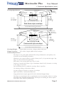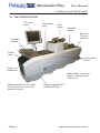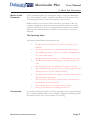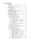
1
Maximailer Plus
1.
Page
Safety Notes
2
Technical Specification
3
2.
Machine Layout Guide
2.1 Description of Machine
2.2 Parts Identification
7
7
8
3.
About this Document
9
4.
The Run Screen
To Change the User or Job
To Adjust Envelope Inserter
To Adjust Document Inserter
10
12
13
15
5.
5.6
5.7
5.8
The Setup Screen
Explanation
The List Box
The OMR Code Screen
The Barcode/Label Screen
The Documents Screen
The Envelopes Screen
The Configuration Screen
Configuring the Inserter
Inserter Options for Inserter Unit
Document Options for Feed Unit
Feed Options for Feed Unit
Postage Options
Output Options (Batching)
Miscellaneous Options
The Job Screen
The Users Screen
The Statistics Screen
17
17
18
19
21
23
25
27
27
28
29
30
32
33
34
35
36
37
6.
Running the Job
41
7.
Setting up the Machine
Loading the Paper & Env. Hoppers
Setting the Separator Gap
42
42
43
8.
Operator Maintenance
44
5.1
5.2
5.3
5.4
5.5
MAXIMAILER PLUS OPERATING INSTRUCTIONS
Part Number K1216A Issue 2 December 2006
Contents
User Manual
Page 1
Maximailer Plus
User Manual
Safety Precautions
Observe the following safety precautions at all times when running the Maximailer
Plus
•
Be sure you know how to switch the machine off in the event of an emergency. This
should be done by opening any of the covers.
•
Do not try to use this machine until you have read these Operating Instructions and are fully
conversant with its operation.
•
Keep loose clothing, long hair and jewellery clear of all moving parts.
•
Do not touch any moving parts. When opening the covers, ensure that all moving parts have
come to a halt before touching them.
•
Do not attempt to dismantle any part of the machine, or remove any fixed covers - this could
result in risk of electric shock or fire. If service attention is required, call a PFE authorised
Service Engineer.
•
When cleaning sensors, use only non-flammable airdusters, such as supplied by PFE (part
number E0070A). Other types may use flammable propellants, which could result in fire or
explosion.
•
If damage to any cover has occurred, it must be replaced by a PFE authorised Service Engineer.
•
If any access cover safety switch fails allowing the machine to continue operating when the
cover is opened, call a PFE authorised Service Engineer immediately.
•
Do not cover any vents or openings, or overheating may result.
•
Avoid placing piles of stationery or other objects on top of the machine - they could topple
off and create a hazard.
•
Do not attempt to operate the machine with stationery outside the limits shown in the specifications.
•
Ensure you have free access all round the machine for loading paper hoppers etc. Do not
place surrounding furniture or other objects where your path may be obstructed.
PUT SAFETY FIRST!
Page 2
MAXIMAILER PLUS OPERATING INSTRUCTIONS
Maximailer Plus
User Manual
1. Technical Specification
SECTION 1
TECHNICAL SPECIFICATION
Form Sizes
Insert Feeder Unit
Insert Sizes - Single Hopper
Depth:
76mm (3”) min. for module 1
89mm (31/2”) min. for following modules
152mm (6”) max.
Width:
165mm (61/2”) min.
241mm (91/2”) max.
Thickness:
60 gsm (16lbs bond) min.
4mm (5/32”) booklets max.
See also notes on following page.
Hopper
capacity:
Up to 300 reply-paid envelopes or 150 2mm booklets.
Insert Sizes - Dual Hopper & OMR Feeder
Depth:
76mm (3”) min. for module 1 (either or both hoppers & OMR)
89mm (31/2”) min. for following modules
152mm (6”) max.
Width:
165mm (61/2”) min.
241mm (91/2”) max.
Thickness:
60 gsm (16lbs bond) min.
4mm (5/32”) booklets max. (lower hopper)
2mm (5/64”) booklets max. (upper hopper)
See also notes on following page.
Hopper
capacity:
Up to 200 reply-paid envelopes or 100 2mm booklets.
Datacard Turnover Interface Unit
Document Sizes
Width:
222mm (8.75”) max. (min. as for insert feeder)
Folded length: 150mm (5 7/8”)
Thickness:
MAXIMAILER PLUS OPERATING INSTRUCTIONS
3mm (1/8”) max.
Page 3
Maximailer Plus
User Manual
1. Technical Specification (cont.)
Minimum clearance of insert pack inside envelope:
Up to 3mm
thick pack:
Depth 6mm (1/4”)
Width 14mm (9/16”)
3-6mm
thick pack:
Depth 10mm (3/8”)
Width 19mm (3/4”)
Total Pack thickness for insertion:
6mm (1/4”) max.
NOTE: – Insert Requirements for Optimum Running
Inserts should be sufficiently flexible to suit the transport path restraints.
The maximum allowable width difference between inserts is 32mm (1¼”). If this difference in
width is exceeded the insertion fingers will not cover the side edges of the narrow insert and cause
an insertion problem.
Sandwiching a narrow insert between two wider ones may resolve this.
Inserts should be dimensionally symmetrical for optimum running. Asymmetric inserts (eg. thicker
on one side than the other) will not seat well in the feed hopper and this can affect feed and
separation. Part loading of the hopper can overcome this but it will require more frequent loading.
Inserts should be flat and free from distortion. Care must be taken in the storage of inserts –
inadequate stacking by a supplier can result in curved edges and spines, causing inserts to seat
poorly in the feed hopper. Feeding of booklets can be particularly adversely affected by distortion.
Booklets require a spine to edge thickness ratio of less than 1.25:1 for optimum running. This can
have a major effect on how well booklets load into a feed hopper and consequently the feeding
efficiency.
A minimum overlap or clearance of 5mm (3/16") is required between an insert edge and the
innermost edge of the carrier envelope side seam. If the edge of an insert runs close to the edge
of the side seam it is liable to catch, making it twist. This will cause insertion problems.
Non-standard feed wheels are available in different materials and geometries. These can prove
effective to overcome slow feeding on some inserts – contact Technical Support for details.
Page 4
MAXIMAILER PLUS OPERATING INSTRUCTIONS
Maximailer Plus
User Manual
1. Technical Specification (cont.)
Envelope Specification
Flap Shoulder Angle
50°Min. 90°Max.
Body Depth
Max.165mm(61 2")
Min. 89mm(31 2")
Min.
10mm
13
( 32")
Minimum open
throat area
Min. 10mm
(13 32")
Throat angle
5°Min. 20°Max.
Min.70mm (23 4")
Horizontal portion of throat
Max. = Envelope Width - 75mm(3")
Flap Length
Max.50mm( 2")
Min.32mm(11 4")
Throat Depth
Max.22mm(7 8")
Min.10mm(13 32")
Side Seam style envelope
Envelope Width Max.264mm(103 8") Min.178mm(7")
Flap Shoulder Angle
50°Min. 90°Max.
Min.
10mm
(13 32")
Minimum open
throat area
Throat angle
5°Min. 20°Max.
Min.70mm (23 4")
Body Depth
Max.165mm(61 2")
Min. 89mm(31 2")
Horizontal portion of throat
Max. = Envelope Width - 75mm(3")
Min. 10mm
Flap Length
(13 32")
Max.50mm( 2")
Min.32mm(11 4")
Throat Depth
Max.22mm(7 8")
Min.10mm(13 32")
Commercial style envelope
Envelope Width Max.264mm(103 8") Min.178mm(7")
Envelope Weight:
70gsm (18lbs bond) min., 100gsm (26lbs bond) max.
Hopper Capacity:
Up to 400 of 80gsm (20lbs bond) envelopes.
General Requirements
Envelopes to be good quality machine-fill envelope. Dimensions and quality to be
consistent across manufacture batches.
Windows to be securely affixed to within 1.5mm (1/16") of top and side edges. Top
edge to be flat and free from puckering.
Side seams to be securely glued up to top of seam.
Position of internal side seams to give a minimum 5mm (3/16") clearance or overlap
to the edge of any insert.
Pre-scored flap crease to enable the envelope flap to open flat.
No twisting, curling or distortion evident.
No glue seepage on interior or exterior of envelope.
Paper smoothness: 100-200 Sheffield units.
Large printed areas require approval from the Technical Support Dept.
Envelopes not meeting the above requirements may be acceptable, subject to testing
and approval by Technical Support Dept. Envelopes not meeting the above requirements may affect machine performance.
MAXIMAILER PLUS OPERATING INSTRUCTIONS
Page 5
Maximailer Plus
User Manual
1. Technical Specification (cont.)
General Specification
Speed:
Variable up to:
3000 filled envelopes per hour (any fold).
Noise level:
Less than 75dbA (3 x feeders, 1 x DTI, measured at 1.6m height, 1m
from nearest cover) - excludes noise level of Card Processor.
Heat Output (BTU/Hour):
Rated current x rated volts x 3.412 (eg. 2354 BTU/Hour for typical configuration of 3 x feeders + DTI) - excludes heat output of Card Processor.
Heat Output (Watts):
Rated current x rated volts (eg. 690W for typical configuration of 3 x feeders +
DTI) - excludes heat output of Card Processor.
Electrical:
230VAC
115VAC
Frequency
50Hz
60Hz
Input Current
Head: 1A
Head: 2A
Feeder: 0.5A
Feeder: 0.5A
Dual Feeder: 0.5A
Dual Feeder: 0.5A
OMR Feeder: 0.5A
OMR Feeder: 0.5A
DTI: 0.5A
DTI: 0.5A
T6.3A
T10A
Fuse Rating
(Insert Head)
Weights (nett):
Page 6
Inserter Head
56Kg
Feeder
25Kg
Dual Feeder
44Kg
DTI
25Kg
MAXIMAILER PLUS OPERATING INSTRUCTIONS
Maximailer Plus
User Manual
2. Machine Layout Guide
2.1 DESCRIPTION OF MACHINE
The function of the Maximailer Plus is to feed forms from a Datacard Card Processor and/
or a number of hoppers, fold them in either 'C', 'Z', 'V' or double forward fold (where required)
and insert them into an envelope which is then sealed and ejected. The folded card carrier is
supplied from the Card Processor via an interface which turns it over before feeding it onto the
track; the document will then be orientated correctly for the address position. Further inserts
(cards, cheques etc.) may optionally be collated with the card carrier by collating on the track. All
documents are then gathered in the collation pocket at the inserter head for insertion as one pack
into the envelope.
Forms may be inserted without sealing the envelope, eg. for subsequent hand insertion of card,
gift etc. Multiple insertions may also be used, ie. a preset number of forms are separately fed onto
the insert track each time the feed unit is called. There is a batch processing facility, allowing a
preset number of cycles to be completed before the machine automatically stops.
The machine consists of a number of modules, depending upon the build ordered - these
modules are briefly described below:
a)
b)
c)
Inserter head - Collates all documents in a pocket before insertion, feeds the envelope, inserts the pack and seals the flap.
Insert Feeder - Feeds shortform inserts (cards, cheques, booklets etc.) onto the track
for subsequent insertion. Available as a single feeder with one feed hopper or a tower
feeder with two feed hoppers. An OMR/Barcode version (with one feed hopper) is
also available.
Datacard Turnover Interface - Receives a folded card carrier from a Card Processor,
turns it over to orientate the address correctly and feeds it onto the track for subsequent insertion.
The Maximailer Plus is equipped with PC controlled operating software from where jobs can be
programmed and run. Jobs can be quickly switched from the main screen, and can also be ‘fine-tuned’
to accommodate a small change in job requirement. The number of jobs that can be programmed is
limited only by the capacity of the PC. Input is via touch-screen monitor or keyboard/mouse.
No manual setting of the fold plates or envelope closer is required, these being adjusted
automatically according to the settings in the selected program.
MAXIMAILER PLUS OPERATING INSTRUCTIONS
Page 7
Maximailer Plus
User Manual
2. Machine Layout Guide (cont.)
2.2 PARTS IDENTIFICATION
PC control
panel
Insert/collate
area
Dual
feeder
Standard
feeder
Datacard
Turnover
Interface
Envelope
hopper
Closer
area
Opening side
covers
Output
(see below)
Note: Station 1 is the first
feed unit after the insert/
collate area.
Filled envelopes may be output
into a receiving tray or onto an
optional conveyor.
Page 8
Storage cupboards (PC
under insert head)
MAXIMAILER PLUS OPERATING INSTRUCTIONS
Maximailer Plus
User Manual
3. About this Document
What’s in this
Document
This User Manual guides you through the stages of using the Maximailer
Plus. The machine is entirely software controlled, with all operator functions being performed on the touch-sensitive control screen.
Different levels of user access can be allocated to personnel so that, for
example, configuration operations can be restricted to Supervisors, while
operators will only have access to straightforward running of the machine.
The sections of this document that relate to restricted access are clearly
indicated.
The Operating Steps
The functions described in this document are:
•
The Run Screen from which you control the running of the
machine.
•
The Setup Screen where you select items that need setting up.
•
The OMR Code Screen to allow you to define OMR marks for
up to four reader heads.
•
The Bar Code Screen to allow you to define Barcode characters.
•
The Documents Screen for defining the forms or inserts to be
used.
•
The Envelopes Screen for defining the envelope to be used.
•
The Configuration Screen where you set up the envelope inserter
and feeder units to use the selected stationery.
•
The Job Screen to allow you to define a job name and associate it
with a machine configuration.
•
The User Screen for creating operator names, and allocating a
password and access permissions.
On-line Help
•
The Statistics Screen for viewing production data.
•
Setting up the machine for loading stationery etc.
To provide assistance through the various operating screens, there will always
be a ? symbol available. Click on this to display a popup box detailing further
information for the area of the software you are using.
MAXIMAILER PLUS OPERATING INSTRUCTIONS
Page 9
Maximailer Plus
User Manual
4. The Run Screen
Starting the
Operating
Program
When you first start the operating program, you will be presented with the
Run Screen, shown below and described in detail on the following page.
The program will start with the last used operator and configuration, as
shown at the top of the screen. To log on as another user. press the ‘User’
button and select one from the list. Enter the password, either by typing it
in, or use the on-screen keyboard and press return (note that the password
is case-sensitive). Assuming the correct password has been entered, the Run
Screen will be available for use, as shown on the following page.
User button
Note: New operators and passwords can be only be entered or edited by
authorised personnel with Supervisor access. This is detailed in section
5.5 ‘The Configuration Screen’ on page 27.
Page 10
MAXIMAILER PLUS OPERATING INSTRUCTIONS
Maximailer Plus
User Manual
4. The Run Screen
The Run screen
explained
From this screen, you run and stop the machine and control the speed. It is
also possible to change the selected user, change the selected job and enter
Edit Configuration (authorised personnel only).
Current time
and date
Select user
Machine
graphic
Reset
count
Output rate
indicator
Speed control
and indicator
Select
job
Autoend
Double
document
calibrate
Exit to setup
screen
Flush
Process
one cycle
Exit
software
Run
button
Stop
button
To change the current user or job, click on the buttons and you will be presented with a list of all
those that have been created, and allow you to select any one. Note that to change to a different
user will require the appropriate password to be entered. To view and adjust the settings for the
envelope and document inserters, click on the relevant part of the machine graphic (see the following page for details).
MAXIMAILER PLUS OPERATING INSTRUCTIONS
Page 11
Maximailer Plus
User Manual
4. The Run Screen (contd.)
To change the
User
To change the
Job
Page 12
Click on the Select User in the logon box
to view the list of user. To change to a
different user, click on the name and enter
the password - you cannot change the user
unless you know their password (note that
the password is case-sensitive). When
changed, you will see the new user name at
the top of the Run screen. To create a new
user, The Setup Screen must be entered
(see page 17).
Click on the Select Job button to view the
list of jobs. To change to a different job,
click on the name and you will see the new
job name at the top of the Run screen. To
create a new job, The Setup Screen must
be entered (see page 17).
MAXIMAILER PLUS OPERATING INSTRUCTIONS
Maximailer Plus
User Manual
4. The Run Screen (contd.)
To adjust the Envelope
Inserter settings
Click on the ‘Unit’ button in the top left corner to
) Note:
toggle between fine tuning for unit and hopper.
Unit Fine Tuning
Click on the envelope inserter
on the machine graphic to
display the fine tuning screen.
Click on Hardware Fine
Tuning to display further
information. You can select:
a: The width of the collate
pocket guides.
b: The overall width of the
insert fingers.
c: The time allowed for the
flap to seal before the envelope
is ejected.
d: Adjustment of the point at which the wetter beam drops to wet the flap.
+ve increases wetting in 1mm steps (moves start point towards insertion
area).
e: Adjustment of the point at which the wetter beam lifts. +ve increases
duration, ie. a greater length of flap is wetted befor the beam is lifted.
f. Adjustment of the amount of envelope travel into the sealing rollers. +ve
= further forward, away from exit direction.
g. Adjustment of the envelope stop position for insertion. +ve = further
forwards, towards exit direction.
h. Adjustment of the amount of insertion of the insert pack into the envelope. +ve = further forwards past the flap crease.
i. Adjustment of the amount of envelope foward travel after flap wetting,
before reversing to enter the sealing rollers. +ve = further forward into the
output rollers, towards the exit direction.
When all adjustments are complete, click on the ‘Unit’ button for
hopper settings, as described opposite.
Important: All fine adustments apply only to the current job and will
not affect any other jobs.
Î
MAXIMAILER PLUS OPERATING INSTRUCTIONS
Page 13
Maximailer Plus
User Manual
4. The Run Screen (contd.)
Hopper Fine Tuning
From here you can adjust
hopper settings. Click on the
inserter hopper, then Document Fine Tuning to display
further information. You can
select:
a: Whether or not the envelope
is sealed. Select ‘Off ’ if, for
example, later hand insertion
of an insert or other item will be required.
b: The setting of the amount of envelope deskew required. Note a higher
level will slow the machine more.
c: Click on the button and adjust width and depth if actual envelope varies
from the settings shown.Warning: if the same document is used on
other jobs as well, the same settings will be applied.
Important: All fine adustments apply only to the current job and will
not affect any other jobs.
Page 14
MAXIMAILER PLUS OPERATING INSTRUCTIONS
Maximailer Plus
User Manual
4. The Run Screen (contd.)
To adjust the
Document
Inserter settings
Click on the ‘Unit’ button in the top left corner to
) Note:
toggle between fine tuning for unit(shown here) and
hopper (shown overleaf). The settings available will
vary between feeders and folders.
Click on the feeder or folder
on the machine graphic to
display the fine tuning screen.
Feeder
No fine tuning of the unit part
of the feeder is available
Î
MAXIMAILER PLUS OPERATING INSTRUCTIONS
Page 15
Maximailer Plus
User Manual
4. The Run Screen (contd.)
Hopper Fine Tuning
(Feeder and Dual Feeder)
From here you can adjust
hopper settings. Click on the
‘Unit’ button and select the
appropriate hopper, and on
Document Fine Tuning to
display further information.
You can select:
a: Whether the unit is turned
on or off. Select ‘Off ’ if, for
example, you wish to leave the
hopper loaded, but temporarily disable it for the job.
b: Whether or not doubles detect is enabled. Select ‘Off ’ if, for example,
the documents being run are substantially different from the calibration
document, such as abnormally dark with heavy printing.
c: Separator Position: if you select a different setting from the one displayed
(as calculated by the software) ensure the physical separator is set to the
same setting, or a warning will be flagged with the first insertion cycle only.
Note: this setting is duplicated in the ‘Configuration’ screen (see page 30).
Whichever is set most recently takes precedence.
d: The setting of the amount of document deskew required. Note a higher
level will slow the machine more.
e: Calibrate Reader: Only available if OMR head is fitted. Click the button
and follow the instructions for calibration.
f: Reader On/Off: Only available if a barcode head is fitted. Switching the
reader on or off is required when aligning.
g: Click on the button and adjust width and depth if actual document varies
from the settings shown.Warning: if the same document is used on
other jobs as well, the same settings will be applied.
Important: All fine adustments apply only to the current job and will
not affect any other jobs.
Page 16
MAXIMAILER PLUS OPERATING INSTRUCTIONS
Maximailer Plus
User Manual
5. The Setup Screen
The Setup
screen explained
From this screen, you make changes to the machine setup. Changes can
then be saved and will remain until they are changed again. To enter the
screen, click the setup button
on the Run screen.
OMR Code
Allows OMR mark settings to be created, viewed or altered.
Bar Code
Allows Bar Code settings to be created, viewed or altered.
Documents
Allows form and insert settings to be defined or altered.
Envelopes
Allows envelope settings to be defined or altered.
Configuration
Configure the machine for all settings to use with the selected stationery.
Job
Create a new job, or alter an existing one.
Users
Allows a new user to be added, and a password and permissions to be set.
These can be also be altered for existing operators.
Statistics
Displays information on current machine settings, production run data etc.
Engineering
Allows testing of various parts of the machine. Only available to personnel
with engineer access, and described in detail in the Automailer 5 Service Manual.
Admin
Allows administration of various machine functions.
Run Screen
Click on this to take you back to the Run Screen.
MAXIMAILER PLUS OPERATING INSTRUCTIONS
Page 17
Maximailer Plus
User Manual
5. The Setup Screen (contd.)
The List Box
Click on any of the buttons on
the Setup screen to display a list
box. Shown left is the list box
for the Document, and is similar
for all of the buttons on the
Setup screen. The list box
shows all of the setups that
have been defined so far. Select
any of the setups shown and
this can then be edited, copied
or deleted by clicking on the
appropriate button at the bottom of the box. New setups can
also be created by clicking on
the New button, and the newly
created item can then be edited
as required. Note that each
name is allocated an ID number
by the software, this being
appended to the name. You can
sort the list by ID or name, and
if the list is long and a scroll bar appears, you can also search the list by name or ID using the
buttons at the bottom. A filter can also be applied, to list only names or IDs containing criteria,
such as a keyword or a part of it.
When either the New or Edit buttons are clicked, the edit screen for that particular setup is displayed. These are explained in detail on the page indicated below:
List Box
OMR Code:
Page 19
Bar Code:
Page 21
Documents:
Page 23
Envelopes:
Page 25
Configuration:
Page 27
Job:
Page 35
Users:
Page 36
If any changes are made to the list box (ie. if an existing item is copied or deleted), the Save button
will be active. Click on this to save the changes, and click Exit. Note that if an item is edited, any
changes will be saved on that particular edit screen, and the Save button will remain dimmed.
Warning!!
For the ‘OMR Code’, ‘Bar Code’, ‘Documents’ and ‘Envelopes’ list boxes, do not delete a
setup that is currently used in any configuration. If you do, the configuration that uses the
setup will be substituted with the factory configuration named ‘Default Config’, which
cannot be deleted or edited (for further details of Configurations, see page 27).
Page 18
MAXIMAILER PLUS OPERATING INSTRUCTIONS
Maximailer Plus
User Manual
5.1 The OMR Code Screen
From this screen you can edit the OMR setup selected in the list box (see page 18), or click on
‘New’ if creating a new setup. The setup name and all OMR settings can be changed as required.
Editing the
setup name.
Click on OMR Name and edit the name as required, either by typing it or
by using the on-screen keyboard. Any changes made here will be reflected
in the OMR Code list box when the OMR screen is saved and exited.
Warning! Do not delete an existing setup if it is used in a current job.
If you do, the factory default will be substituted.
Editing the
settings.
Set the Number of marks, Direction, Parity, First mark position according
to the marks you are using and their printing on the stationery, Security
Count direction and Security Count start (whether 0 or 1). Note that
‘Fixed’ is currently the only available option for pitch.
Also set the Pitch, Read channel (see below), Gate position from TOF,
Leading & Trailing margins (allowable tolerance for printed mark set to
‘drift’ and still be read), Mark threshold (decrease if print quality of marks
is poor, increase if background is dark), Divert oversize group (Y/N),
Divert blank sheet (Y/N), Address on every page (Y/N) and Invisible Gate
Mark (Y/N) – this allows use of a single mark as End of Group.
Channel number: this is assigned to the OMR head according to its
connection on the machine’s PCB. Ensure you are using a channel number
for which has a connection exists (default for 1 head is channel 1).
MAXIMAILER PLUS OPERATING INSTRUCTIONS
Page 19
Maximailer Plus
User Manual
5.1 The OMR Code Screen (cont.)
Now click on each OMR mark position button and enter the type of mark for each position,
according to the marks you are using.
Note: Prior to running a new or edited OMR setup, the machine must first be calibrated
using a calibration sheet (see note below). The results of the calibration will be shown on the
screen for each selected OMR unit.
After making any changes, click the Save button at the bottom of the screen, and then the Exit
button to return to the list box.
Note: For full details of OMR specifications and calibration, see PFE document ‘Specifications
for Maximailer Plus’.
Page 20
MAXIMAILER PLUS OPERATING INSTRUCTIONS
Maximailer Plus
User Manual
5.2 The Barcode/Label Screen
From this screen you can edit the barcode or other ID label setup selected in the list box (see page
18) or click on ‘New’ if creating a new setup. The setup name and all label settings can be changed
as required.
Editing the
setup name.
Click on Barcode name and edit the name as required, either by typing it
or by using the on-screen keyboard. Any changes made here will be reflected in the Barcode list box when the Barcode screen is saved and exited.
Editing the
settings for
non-BCS characters.
The buttons below Name relate to label settings and other non-BCS character functions. These are briefly described below:
Number of characters in label: Up to max. 20 for PFE BCS system.
Label machine control: Available control systems are PFE BCS (default),
and any other available Custom Control. For all except PFE BCS, PFE
Technical Support department must be consulted.
Grouping: Select whether the group mark is End of group, First of group
or Label on first page only (label printed on first page of group, but not
subsequent pages).
Good decode reads: Set the maximum number of good reads required
before label is accepted. Set to low number if print quality is poor.
Security check: Used as a further method of security checking, additional
to, or instead of using security BCS character. Select the character type to
be used for checking.
Î
MAXIMAILER PLUS OPERATING INSTRUCTIONS
Page 21
Maximailer Plus
User Manual
5.2 The Barcode/Label Screen (contd.)
Data log enabled: If selected, a record of the movements of each group
will be retained in a log file which can be viewed later in the Statistics
screen. This data can then be used to compare the original number of
documents with the number of processed envelopes. Choose whether to log
from the label on the first page of a group, or the last. For details of Data
Logging and the Statistics screen, see page 37.
Divert oversize group: If set to ‘Yes’, groups that are too large to fold
will be fed into the divert tray (if fitted) without stopping the machine. If
no tray is fitted, the machine will stop with the group in the accumulator.
Divert blank sheet: As above, but applying to sheets with no label.
Data logging characters: If data logging is being used, click on and enter
the start character position and number of characters. See also page 37.
Customer ID characters: Customer ID can be used for grouping, as an
alternative to the Grouping character. Each form within a group is printed
with the same character(s), with each group using a different character(s).
Editing the
settings for
BCS characters.
Click on and enter the start position and character length of each function,
either by typing it in the ‘Enter Value’ box, or by using the on-screen
keypad. Number 1 is the first mark from the leading edge. ‘0’ (zero) means
that character is not used. Note: a minimum of 4 characters must be used.
See also ‘Barcode Specification for Maximailer Plus’.
Security
Form sequence within a Job: This is used to ensure that forms are
processed through the inserter in the same order that they were printed, and
that there are no missing forms. This is achieved by coding each form as it
is printed with the alphabetic characters A,B,C......Z. The sequence then
restarts at A again. When the forms are read by the barcode reader any
deviation from the correct order is detected and an error produced.
Set the start character position, and whether Incrementing (A - Z), or
decrementing (Z - A).
Form sequence within a Group: As above, but A,B,C.....Z are printed on
each form within the group, then repeated for the next group. Note: if both
Job and Group security are used, Direction must the same for each.
After making any changes, click the Save button at the bottom of the
screen, and then the Exit button to return to the list box.
Page 22
MAXIMAILER PLUS OPERATING INSTRUCTIONS
Maximailer Plus
User Manual
5.3 The Documents Screen
From this screen you can edit the Form/Insert setup that was selected in the list box (see page 18)
or click on ‘New’ if creating a new setup. The setup name and all form or insert parameters can be
changed as required.
Editing the
setup name.
Click on Name and edit the name as required, either by typing it or by
using the on-screen keyboard. Any changes made here will be reflected in
the Documents list box when the above screen is saved and exited.
Warning! Do not edit the name for a Document currently used in any
configuration. If you do, the factory default document ‘A4’ will be used
instead.
Editing the
settings.
Icon: Select the icon from a preset list - this icon that will then appear in the
graphic on the Configuration screen (see page 27).
Form type: Select the form type from a preset list. Select ‘Card Carrier’ for
all documents from a Card Processor.
Width/Depth/Paper Weight: Click on the appropriate button and enter
the required setting for the form or insert width, depth and weight (in the
units shown) - see also Thickness & True Weight on the following page.
Note: width and depth apply to finished (ie. folded) card carrier.
Thickness: If the insert is a booklet or other thick material, click the ‘Computed’ button to uncheck the box, and then click the ‘Thickness’ button.
Enter the required figure in mm. Note that if this function is used Paper
Weight will not be active.
MAXIMAILER PLUS OPERATING INSTRUCTIONS
Page 23
Maximailer Plus
User Manual
5.3 The Documents Screen (contd.)
Editing the
settings (contd.)
True Weight: This shows the weight of the document or insert in the units
shown, and is linked to Thickness above. To enter a known weight, click
the ‘Computed’ button to uncheck the box, and then click the ‘True Weight’
button. Enter the required figure in the units shown. Note that if this
function is used Paper Weight will not be active. The true weight need
only be entered if Postage Rates are being used (see page 33).
Pre-Folded Leaves: If the insert consists of more than one leaf (eg. a ‘Z’
folded flyer), click the button and enter the number of leaves.
OMR Name: Click this button if you are using OMR, then click the
Name button and select an OMR setup (see page 19 for defining OMR
setups).
Label Name: Click this button if you are using barcodes or other labels,
then click the Name button and select a label setup (see page 21 for defining barcode setups).
Document ID: Used to verify that the correct stationery is loaded into the
correct feed unit. If using this feature, set ‘Doc ID Mode’ to ON and define
the alpha-numeric characters being used for the ID. Note that the start
position and length of the characters must be set in the Barcode/Label
screen. See also ‘Barcode Specification for Maximailer Plus’ for a full description of Document ID.
Document Address: If this is the address document, click the ‘Address
Position’ button and select the position that best describes the location of
the address - this will be used by the software to determine the type of fold
and orientation of stationery. Note that the left/right location of the address is not stated, as this will be determined by the printed address matching the lateral position of the envelope window. If it is not the address
document, click ‘None’.
Click the ‘Save as Default’ button if you wish this to be the setup that new
documents will default to.
When all editing is complete, click the Save button at the bottom of the
screen, and then the Exit button to return to the list box.
Notes:
1.
Minimum document width in the pack (including inserts) must be no smaller
than the maximum document width by more than the following: Minimum document width = (Maximum document width/2) + 58mm. eg. if maximum document =
210mm, minimum document width = (210/2) + 58 = 163mm minimum.
Page 24
MAXIMAILER PLUS OPERATING INSTRUCTIONS
Maximailer Plus
User Manual
5.4 The Envelopes Screen
From this screen you can edit the Envelope setup that was selected in the list box (see page 18) or
click on ‘New’ if creating a new setup. The setup name and all envelope parameters can be changed
as required.
Editing the
setup name.
Click on Name and edit the name as required, either by typing it or by using
the on-screen keyboard. Any changes made here will be reflected in the
Documents list box when the Documents screen is saved and exited.
Warning! Do not edit the name for an Envelope currently used in any
configuration. If you do, the factory default document ‘DL’ will be
used instead.
Editing the
settings.
Icon: Select the icon from a preset list - this icon that will then appear in the
graphic on the Configuration screen (see page 27).
Width/Depth/Paper Weight/Flap: Click on the appropriate button and
enter the required setting for the envelope’s width, depth, weight (in the units
shown) and flap length - see also Thickness below.
Thickness: If the envelope is of very thick material or of unknown weight,
click the ‘Computed’ button to uncheck the box, and then click the ‘Thickness’ button. Enter the required figure in mm. Note that if this function is
used Paper Weight above will not be active.
MAXIMAILER PLUS OPERATING INSTRUCTIONS
Page 25
Maximailer Plus
User Manual
5.4 The Envelopes Screen (contd.)
Editing the
settings (contd.)
True Weight: This shows the weight of the envelope in the units shown,
and is linked to Thickness described on the previous page. To enter a
known weight, click the ‘Computed’ button to uncheck the box, and then
click the ‘True Weight’ button. Enter the required figure in the units shown.
Note that if this function is used Paper Weight will not be active. The true
weight need only be entered if Postage Rates are being used (see page 33).
Amount of wetting required: Different envelope types may require a
greater or lesser amount of wetting for an effective seal. If you wish to
change from the default setting of 3, click the appropriate button where
setting 1 is the least, 4 is the greatest.
OMR Name: This function is not available for envelopes.
Label Name: Click this button if you are using barcodes or other labels for
verification checking at output, then click the Name button and select a label
setup (see page 21 for defining barcode setups). Note that the label can be
printed either on the document (for reading through the window), or on the
envelope.
Click the ‘Save as Default’ button if you wish this tp be the setup that new
documents will default to.
When all editing is complete, click the Save button at the bottom of the
screen, and then the Exit button to return to the list box.
Page 26
MAXIMAILER PLUS OPERATING INSTRUCTIONS
Maximailer Plus
User Manual
5.5 The Configuration Screen
From this screen you edit configurations that were created in the List Box after clicking the ‘Configuration’ button in the Setup screen (see page 17) or click on ‘New’ if creating a new configuration. A configuration applies the settings to be used for the envelope inserter and all the stations
fitted, which is then associated with a Job (see page 35). You can rename a new configuration by
clicking on the Name button and editing as required, either by typing or by using the on-screen
keyboard. Warning! Do not change the name of an existing configuration that is associated
with a current job. If you do, the factory configuration ‘Default Config’ will be substituted.
Configuring the
inserter.
Click the upper icon on the ‘Head’ part of the graphic (showing the envelope icon). This displays the list of available envelopes to allow you to
select one (see page 25 for creating Envelopes). If the machine has more
than 6 stations, use the scroll arrows to move sideways.
Select the required
envelope and click ‘Ok’.
An error will occur if an
) Note:
envelope that is used in any
configuration has been deleted
from the list box in the Setup
screen (see page 18).
MAXIMAILER PLUS OPERATING INSTRUCTIONS
Page 27
Maximailer Plus
User Manual
5.5 The Configuration Screen (contd.)
Setting the
inserter options
for the Inserter
unit
Click on the bottom section of the Inserter (showing the unit icon), and the
following dialog box appears:
‘Save as
) Select
Default’ to make
this the default for all
new setups. These
settings then apply to
‘Load Default’
Seal Mode:
Options are Off / Always / Unseal OMR Select /
Off Flap Open (if ‘Off ’ is selected, flap is closed without sealing).
Deskew:
The setting of the amount of envelope deskew
required. Note a higher level will slow the machine more.
Item ID:
Page 28
If available for setting. must be set to Item ID 1.
MAXIMAILER PLUS OPERATING INSTRUCTIONS
Maximailer Plus
User Manual
5.5 The Configuration Screen (contd.)
Setting the
document options for the
Feed unit
Click the upper icon on one of the numbered units (showing the document
icon. This displays the list of available documents to select (see page 23 for
creating documents). If the list is long, a ‘Find’ box will appear to enable
you to search the list using keywords. If more than one incidence of the
search result occurs, the ‘Next’ and ‘Previous’ buttons will be active.
Select the required
document and click ‘Ok’.
)
Note: An error will occur if a document that is
used in any configuration has been deleted from
the list box in the Setup screen (see page 18).
MAXIMAILER PLUS OPERATING INSTRUCTIONS
Page 29
Maximailer Plus
User Manual
5.5 The Configuration Screen (contd.)
Setting the feed
options for the
Feed unit
Click on the lower icon of the numbered feed unit (showing the unit icon),
and the following dialog box appears:
Note that the
)
options in the dialog
box may vary from
those shown, depending on whether
the unit is a feeder
or a folder.
‘Save as
) Select
Default’ to make
this the default for all
new setups. These
settings then apply to
‘Load Default’
Address Carrier:
Select whether or not this is the address document.
Note: this can also be selected from ‘Miscellaneous’ (see page 35). Whichever is set the later takes precedence.
Feed Control Mode: Options are: Off / Feed Always / OMR or
Barcode Select (the latter only available if unit is OMR/Barcode enabled).
Fold Mode:
(3-plate folder only) Options are: Singly / Together
/ Via accumulator (the latter is only available if the unit has an accumulator fitted: if so, forms will group in accumulator first before folding.only).
Form Count:
Only available if ‘Mark reading’ is Off. If multiple
forms are required, set this to the required quantity. Note: ensure that the
maximum fold capacity is not exceeded.
Mark Reading:
Only available if unit is OMR/Barcode and a
marked document is selected. Options are: Off / OMR marks / Barcode
labels / 2D Datamatrix / OCR.
Thickness Doubles: Set to ‘Off ’ if, for example, the documents being
run are substantially different from the calibration document, such as
abnormally dark with heavy printing.
Set the amount of envelope deskew required. Note a higher
level will slow the machine more.
Deskew:
Options are: Auto / Nos. 2 - 17. Use ‘Auto’ unless select feed
marks are being read; ‘Item ID’ then allows a number to be assigned to each
unit to identify with the select feed mark.
Item ID:
Page 30
MAXIMAILER PLUS OPERATING INSTRUCTIONS
Maximailer Plus
User Manual
5.5 The Configuration Screen (contd.)
Default Separator Position: Only available on feeder or dual feeder and
is a read-only display. Indicates the separator position calculated by the
software. If the physical separator is set differently from this, a warning will
be flagged for the first insertion cycle only.
Only available on feeder or dual feeder. If you
select a different setting from the one displayed in ‘Default Separator
Position’ (see above) ensure the physical separator is set to the same setting,
or a warning will be flagged with the first insertion cycle only. Note: this
setting is duplicated in the ‘Fine Tuning’ screen (see page 16). Whichever is
set most recently takes precedence.
Separator Position:
Feeds from previous or next unit if feeder runs out of
inserts. Settings available will depend upon hardware fitted and location of
hopper. ‘Above’ and ‘Below’ apply to multi-hopper units. ‘Left’ and ‘Right’
apply to single-hopper units as viewed from the operator standpoint.
Cascading:
MAXIMAILER PLUS OPERATING INSTRUCTIONS
Page 31
Maximailer Plus
User Manual
5.5 The Configuration Screen (contd.)
Setting the
postage options
Ensure that the Postage tab in the configuration screen is selected. This
section allows you to define weight groups for setting different postage rates.
The filled envelopes can then be diverted to different locations, according to
the weight range that they fall within. If you will not be using postage rates,
these settings can be ignored. Note: This screen will only be available to
personnel with Supervisor access.
)
Select ‘Save as
Default’ to make
this the default for
all new postage
setups
Setting the
weight group
thresholds
There are four weight groups, each one defining a range with a lower and
upper weight, and a postage rate to be set for that range. The upper weight
that you set for each group will automatically appear as the lower weight for
the following group, enabling an ascending scale of postage rates to be set
for the four groups.
To set the threshold for the first group, click the Weight Group 1 button
and enter the upper weight of the range in grams. Press ‘Enter’.
Setting the
postage rates
To set the postage rate for Group 1, click the Postage button, and enter the
rate for that group. Press ‘Enter’.
Repeat the above steps for the remaining groups (if required).
Note: The weight of the filled envelope is determined by the weight of each
inserted document, and the envelope. These are set in the Document and
Envelope options in the Setup screen (see pages 23 & 25).
Page 32
MAXIMAILER PLUS OPERATING INSTRUCTIONS
Maximailer Plus
User Manual
5.5 The Configuration Screen (contd.)
Setting the
output options
Ensure that the Output tab in the configuration screen is selected. This
section allows you to set up batching on the output conveyor (where fitted).
Note: This screen will only be available to personnel with Supervisor
access.
This op)
tion is only
available if a
conveyor is
fitted.
Select ‘Save
)
as Default’ to make
this the default for
all new setups
Envelope
batching
If batching is used, the machine will either stop, or wait for a predetermined
time period to allow removal of envelopes before restarting.
To use batching, press the Output Conveyor button and select ‘Batch on’.
Press the Control button to display the settings dialog, as shown above.
The only Quantity mode available is ‘Envelopes count’. Set the required
quantity either by typing it in or using the on-screen keyboard.
For Control mode, select ‘Auto-restart’ (machine will pause for a set length
of time and then restart - see below for ‘Pause time’) or ‘Pause’ (machine
will stop and will only restart when the Run button is pressed).
Jog step allows a gap between envelope batches to be set on the conveyor.
The units shown are multiples of the envelope overlap, as adjusted by the
knob on the conveyor. This means a suitable gap can be set without disturbing the knob.
Pause time is the number of seconds before the machine auto-restarts.
After making any changes, click the Save button at the bottom of the
screen, and then the Exit button to return to the list box.
MAXIMAILER PLUS OPERATING INSTRUCTIONS
Page 33
Maximailer Plus
User Manual
5.5 The Configuration Screen (contd.)
Setting the
miscellaneous
options
Ensure that the Miscellaneous tab in the configuration screen is selected.
This section allows you to select the required station for data logging
(where used), and also for the address carrying document. Note: This
screen will only be available to personnel with Supervisor access.
Setting the
datalog unit
If you are using datalogs, set the unit you wish to use to record the log from
by pressing ‘Logging from’. By default, this will be the prime unit. See page
39 for further details of datalogs.
Address Carrier
This allows you to select the unit that carries the address document (usually
the prime unit). Note: this can also be selected from ‘Feed options for feed
unit’ (see page 30). Whichever is set the later takes precedence.
Confirm
calibration
Select ‘No’ if you wish the machine to continue running after a calibration
cycle is performed (by defaut, machine will stop and await confirmation of
envelope contents.
After making any changes, click the Save button at the bottom of the screen,
and then the Exit button to return to the list box.
Page 34
MAXIMAILER PLUS OPERATING INSTRUCTIONS
Maximailer Plus
User Manual
5.6 The Job Screen
From this screen you can edit the job that was selected in the list box (see page 18), or click on
‘New’ if creating a new job. The job name can be changed and/or a different configuration associated with it.
Editing the job
name.
Click on Job Name and edit the job name as required, either by typing it or
by using the on-screen keyboard. Any changes made here will be reflected
in the Job list box when the Job screen is saved and exited.
Selecting a
configuration.
Click on Configuration and select an existing one from the list, if any. To
create a new configuration, see ‘The Configuration Screen’ on page 27.
Note: A configuration can be associated with as many jobs as you wish.
Logging OCR
data
Click on Log OCR data if you are using an OCR scanner on the output
and need to log the data gathered. Select ‘On (CommPort)’ if you wish to
log data via the PC port. Select ‘Display verification read’ to display data on
the Run screen as well as log to file. The file will be stored in the
Data\DataLogs directory on the hard disk, and will take the format
ocr_<Jobname>_<Date>.txt (‘ocr’ will vary for different data types).
Late divert
Set this to ‘Yes’ to use customer’s own data file to divert using the ID field
label instead of the Divert BCS Character. Set to ‘On’ to divert for this job
only, or set to ‘All’ to divert on occurrence of label in any job. Note that the
Divert BCS character can also be used in conjunction with ID field label.
Checking
Not currently used.
MAXIMAILER PLUS OPERATING INSTRUCTIONS
Page 35
Maximailer Plus
User Manual
5.7 The Users Screen
Note: This screen will only be available to personnel with Supervisor access.
From this screen you can edit the user that was selected in the list box (see page 18), or click on
‘New’ if creating a new user. The user name, password and access levels can be changed.
Editing the
password.
Click on Password and edit the password as required, either by typing it or
by using the on-screen keyboard. This is the password that must be entered
when the user is selected from the Run screen. Note: the password is casesensitive
Editing the user
name.
Click on User name and edit the name as required, either by typing it or by
using the on-screen keyboard. Any changes made here will be reflected in
the User list box when the Users screen is saved and exited.
Setting the
roles
Check the boxes as required to set the roles (access levels) that are to be
allocated the user. To provide access to all roles, select ‘Superuser’.
For further explanation of the roles, contact PFE Technical Support.
After making any changes, click the Save button at the bottom of the
screen, and then the Exit button to return to the list box.
Page 36
MAXIMAILER PLUS OPERATING INSTRUCTIONS
Maximailer Plus
User Manual
5.8 The Statistics Screen
Note: This screen will only be available to personnel with Supervisor access.
From this screen you can view information for each event that took place for every job run to date,
back to the last archive (see page 40 for details of archives).
Your first action should be to filter out data relevant only to what you wish to know, as decribed
below:
Filter
Press the ‘Filter’ button and set the filter criteria by date, and also by
specific job and/or operator, if required (by default, all jobs and operators
will be assumed). Select ‘Custom’ to choose any start/end date, or weekly/
monthly start date. Press the date buttons for a calendar.
When the required criteria have been set, select OK. Press the ‘Show event
data’ button for a list of events similar to that shown in the Event Data
screen above. Note that the button toggles between ‘show’ and ‘hide’. You
can also view a summary of this information, as described on the following
page:
MAXIMAILER PLUS OPERATING INSTRUCTIONS
Page 37
Maximailer Plus
User Manual
5.8 The Statistics Screen (contd.)
View Summary
Press the ‘Summary’ button to view the filtered data. Note that only valid
events will be shown, ie. those that involved documents being fed (a machine
configuration event, for example, would not be shown).
Select an event and press ‘OK’ to view the summary, as shown above. Note
that you can also select more than one event by selecting the first in a range,
holding down the shift key and then selecting the last in the range.
Alternatively, all events can be selected by pressing the ‘Select All’ button.
If a printer is connected, the summary can be printed by pressing the ‘Print’
button. The data will be collated and printed in portrait format.
Current & Previous sessions
Press the ‘Current’ button to view only the events that have occurred since
last logging on. The ‘Previous’ button shows events up to the last new logon.
If a new archive is opened (see page 40), the ‘Previous’ button will restore
the events that were displayed prior to its opening.
continued overleaf
Page 38
MAXIMAILER PLUS OPERATING INSTRUCTIONS
Maximailer Plus
Data Logs
User Manual
Data Logs are created automatically whenever the machine is run. A
separate log is created for Events, Document Outputs, Errors, OCR data
(where applicable, Postage and Others (as yet undefined). These are text
files and are named according to their type, followed by the jobname and
date (see example below). If a job is finished, then returned to later, the
same log files will be added to, even if another job had been run between
the two runs.
To view the logs, press the ‘Data Log’ button and select the required log, as
shown below:
Points to note
1.
Data is logged using only the barcode characters selected in the
Barcode screen (see page 21). This can be all of the characters.
2.
Data Log files are created on the computer disk in the following
location:
C:\Program Files\Pfe\Maximailer Plus\Data\DataLogs
For full details of analysing Data Logs, see PFE document ‘Data
Logging for Automailer 5’.
MAXIMAILER PLUS OPERATING INSTRUCTIONS
Page 39
Maximailer Plus
User Manual
5.8 The Statistics Screen (contd.)
Open Archive
Select ‘Open Archive’ on the Statistics Diagnostics screen to display the
details of archives, selected by date. Archives are automatically created for
each session and are saved on the computer until the end of the current
month. At the end of the month, all session archives are collected into one
archive and named as that month and the year. For example, on the first day
of June, all session archives for April will be available in a single archive
named ‘Apr’, followed by the year. All data up until the end of the month
can be seen from the main Statistics screen by pressing ‘Show events data’,
as previously described. Archives are stored on the PC of the Maximailer
Plus at:
C:\Program Files\Pfe\Maximailer Plus\Data\Archives\*.DB
archives
) Monthly
are shown - see
text below for
archive format.
After selecting the archive, press the ‘View event data’ button to display its
contents. To return to the data being displayed before the archive was
selected, press the ‘Current Session’ button and then the ‘Filter’ button
again - the dates originally entered will still be in place.
Archives are created daily monthly (in the format Mmm_yyyy), and for
faults (in the format F_mmddyy_n).
‘All Other Archives’ refers to any older or legacy archives remaining on the
PC that may be required for later examination.
‘All Archives’ provides access to all of the above, shown in one list.
Page 40
MAXIMAILER PLUS OPERATING INSTRUCTIONS
Maximailer Plus
User Manual
6. Running the Job
Using the Configuration.
Now that you have finished defining a configuration, it can be associated
with a Job. Click on Job in the Setup screen and select the configuration, as
described in the ‘The Job Screen’ on page 35.
Running the
Job.
When you have associated the configuration with a Job, click on Run
Screen in the Setup screen shown above. This will return you to the Run
screen, where you can commence operating, as described in ‘The Run Screen’
on page 10. Before running the job, ensure that the machine is loaded with
stationery, and is properly set up - see ‘Setting up the Machine’ on page 42.
Note: A configuration can be associated with as many jobs as you
wish.
MAXIMAILER PLUS OPERATING INSTRUCTIONS
Page 41
Maximailer Plus
User Manual
7. Setting up the Machine
7.1 LOADING THE PAPER HOPPERS
Insert Feeder (Single, Dual, OMR/Barcode)
Slacken the locklever and adjust
the side guides to
give 1 - 2mm
clearance across
the width of the
inserts. Tighten
the lock lever.
Pull the weighted roller back and load the
inserts, ensuring they are fully down.
Release the weighted roller so that it ‘tips’
the inserts into the pickup roller.
An alternative heavier roller is also available (part no. C3656A) which can improve
feeding of thick booklets. This must be
fitted by a PFE Service Engineer.
Note: A single feeder is
shown – if the unit is a
dual or OMR/Barcode
feeder, the method of
loading is identical, but
the hopper capacities are
different; see ‘Technical
Specification’ on page 3.
7.2 LOADING THE ENVELOPE HOPPER
Slacken the locklever and adjust
the side guides to
give 1 - 2mm
clearance across
the width of the
envelopes.
Tighten the lock
lever.
Page 42
Pull the weighted roller back and load the envelopes, ensuring they are
fully down - flaps must be facing forwards. Release the weighted roller
so that it ‘tips’ the envelopes into the pickup roller.
An alternative heavier roller is also available (part no. C3656A) which
can improve feeding of thick booklets. This must be fitted by a PFE
Service Engineer.
MAXIMAILER PLUS OPERATING INSTRUCTIONS
Maximailer Plus
User Manual
7. Setting up the Machine (contd.)
7.3 SETTING THE SEPARATOR GAP
The feeder separator has 4 settings, marked A to C on the slide. Before running the job, the gap
must be set to suit the thickness of material being processed - this prevents more than one item
being fed at a time. Note that there is an intermediate setting between each marked position,
allowing finer adjustment.
Lower the side
cover and move
the slide to suit
the thickness of
the insert.
Slide positions:
A = 0 to 0.75mm
B = 0.75 to 1.5mm
C = 1.5 to 2.5mm
D = 2.5 to 4.0mm
(A - C only on Tower
Feeder)
)
MAXIMAILER PLUS OPERATING INSTRUCTIONS
Most jobs will use
position A. If you
use the wrong
setting, an error
will appear on the
control panel.
Page 43
Maximailer Plus
User Manual
8. Operator Maintenance
8.1 CLEARING PAPER CRASHES
If a paper crash occurs, the machine will stop and indicate the position of the crash on the screen.
Clear the crash as shown below, then press the Run button to resume operating.
Insert head and feeder
Raise the top perspex cover and small
feeder cover. Lift the green latch bars
as shown to access the paper paths
below. Carefully withdraw any
jammed paper, taking care not to tear
it. To clear a crash in the feeder,
lower the feeder side cover and swing
the green handles upwards to access
the paper paths. If necessary, use the
green knob to turn the shafts for
‘winding out’ jammed paper.
If a jam occurs at the input of the
envelope or feeder hoppers, remove
all material and withdraw the jammed
item. For feeders, ensure that the
separator gap is correctly set (see page 43). For the envelope hopper, if jams occur frequently,
contact the Service Department.
Dual feeder & OMR Feeder
If a paper crash occurs, this is most
likely to be at the eject sensor at the
exit. To clear the jam, it can be awkward
to pull the paper out if raising the roller
carrier at the exit. An easier method is
described below:
1.
Lower the operator side cover of
the dual feeder, and of the feed
unit in front (if the unit in front is
the insert head, raise the perspex
cover).
2.
Use the green knob on the feed
unit in front to swing down the lower conveyor, or raise the rearmost clam assembly if the
unit in front is the insert head.
3.
Turn the green knobs on the dual feeder to wind the crashed document into the cavity ahead
– it can then be easily removed.
Page 44
MAXIMAILER PLUS OPERATING INSTRUCTIONS
Maximailer Plus
User Manual
8. Operator Maintenance (contd.)
8.2 CLEANING ROLLERS AND SENSORS
Periodically, all rollers, feed wheels and sensors should be cleaned, especially if a long run is
envisaged. Use only PFE Rubber Riller Restorer Fluid (part no. E0483A), except for the pick-up
rollers on the feed and envelope hoppers - these must be cleaned using only a cloth dampened with water. Clean the full circumference of rubber rollers, feed wheels and conveyors in the
area of:
a)
Feeder and envelope hoppers
b)
Insert area at the head end
c)
Closer area at the head end
Ensure the machine is switched off before cleaning rollers or sensors.
To access rollers in the insert area, raise the perspex cover and lift the green handles to reach the
paper path. Rotate rollers by hand when cleaning.
To access feeder rollers, lower the LH side cover and lift the infill cover in front of the hopper.
Use the green knob to rotate the rollers for cleaning. Note: after a long period of time, some
inserts can cause a jam with the insert stuck between the rollers - this may especially occur on
coated material. If this happens, open the upper roller plate with the green latch and using a cloth
dampened with Roller Cleaning Fluid, clean all the rollers, both upper and lower. Use the green
knob to help rotate them.
Clean all 12 rollers
Cleaning sensors
When cleaning the rollers, the sensors should also be cleaned by blowing away dust and debris
using the supplied airduster. It is important that sensors are regularly cleaned, or operating
errors may occur. Locations are shown on the following page - note that each sensor is in two
halves, receiver and transmitter. Both halves must be cleaned.
Use only non-flammable airdusters, such as supplied by PFE (part no. A0070A).
MAXIMAILER PLUS OPERATING INSTRUCTIONS
Page 45
Maximailer Plus
User Manual
8. Operator Maintenance (contd.)
Cleaning sensors (contd.)
Insert and collate area
For all positions shown, direct the jet of air onto the sensors, indicated by arrows in the following
views. Note that sensors are in two halves, receiver & transmitter - both halves must be cleaned.
Open the perspex cover and front feeder
cover, then lift the front-most green handle to
raise the mechanism - this is held in the raised
position by a latch.
For the sensor pairs, liberally spray the
air jet in the gap between them.
Feeders
Lower the feeder side cover and raise
the top cover. Swing the green latch
upwards to raise the roller platten.
Note: station 1 feeder is shown others are similar.
Page 46
MAXIMAILER PLUS OPERATING INSTRUCTIONS
Maximailer Plus
User Manual
8. Operator Maintenance (contd.)
Dual Feeder
Open the cover in front of the feeder trays and direct a jet of air onto the sensors shown by the
arrows in the diagram below. Ensure that all sensors, including those inside the pivoting cover are
thoroughly cleaned as some sensors are located deep behind the apertures.
Closer area
Open the closer cover below the envelope hopper and direct the jet of air onto the sensors, indicated by arrows in the following view. For the sensor pairs, liberally spray the air jet in the gap
between them.
MAXIMAILER PLUS OPERATING INSTRUCTIONS
Page 47
Maximailer Plus
User Manual
9. Operator Maintenance (contd.)
Datacard Turnover Interface
On the DTI, there are sensors on the cassette and conveyor.
To access the conveyor sensors, raise the top cover and lift the upper conveyor.
The cassette down and cassette exit sensors are located low down at the cassette side plates. They
are of the forked type – before cleaning rotate the flag clear of the sensor.
Page 48
MAXIMAILER PLUS OPERATING INSTRUCTIONS
Maximailer Plus
User Manual
9. Operator Maintenance (contd.)
9.3 MAINTAINING THE WETTING SYSTEM
The wetter tank supplies the fluid for wetting the envelope flaps and needs topping up from
time to time. It is located on the left hand side of the machine, below the closer area at the
output. To gain access, lower the side cover on the insert head. Fill the tank through the
spout until the level reaches the indicator visible inside - be careful not to overfill.
Note: Use only PFE Envelope Sealing Fluid A0276A, as this has been specially
formulated for greatly enhanced sealing and antibacterial qualities.
Fill through the spout
as shown, up to the
level indicator.
Withdraw the tank by
using the green tab
Check the condition of the sponge at regular intervals and clean off gum residues as required. Remove the wetter tank to do this by lifting the end slightly using the green tab, then
withdraw it. Note: use a piece of absorbent material to under the drain tube to catch
any drips. Clean the sponge under running water and replace the tank, ensuring it is fully
located. After cleaning, or if the sponge has dried out, it should be primed by immersing it
in Envelope Sealing Fluid.
If the machine is to be left unattended for more than a week, it is advisable to remove the
tank and drain it. Wipe dry after washing to prevent contamination.
The tank must also be removed if the machine is moved, and the reservoir
drained. The reservoir can be drained by pulling out the plastic drain tube tucked underneath it and pulling out the bung to drain into a suitable receptacle.
MAXIMAILER PLUS OPERATING INSTRUCTIONS
Page 49
Maximailer Plus
User Manual
Blank Page
Page 50
MAXIMAILER PLUS OPERATING INSTRUCTIONS