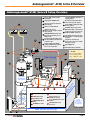
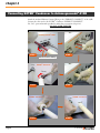
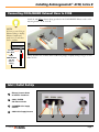
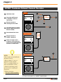
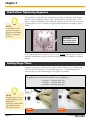
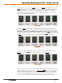
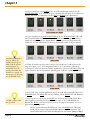
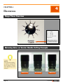
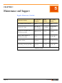
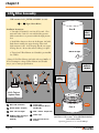
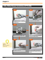
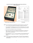
1
TABLE
OF
CONTENTS
Chapter 1
Automegasamdri®-915B, Series B Overview
Automegasamdri®-915B, Series B CPD Dryer
2
Automegasamdri®-915B, Series B Setup Overview
3
Chapter 2
Installing Automegasamdri®-915B, Series B
Preparation of Installation Site
4
Installation of the Automegasamdri®-915B, Series B
4
Chapter 3
Operating Automegasamdri®-915B, Series B
Operating Automegasamdri®-915B, Series B
Chapter 4
11
Illustrations
Purge Timer Overview
16
Metering Valve w/ Vernier Handle Setting Example
16
HF Compatible Insert View
17
Chapter 5
Maintenance and Support
Regular Maintenance Schedule
18
Chamber Care
19
LCO2 Filter Assembly
20
LCO2 T-filter Element Installation
22
FAQ
23
Spare Parts List
27
Warranty
28
Repackaging for Shipment
28
Appendix
A. Backing Ring and Chamber O-Ring Installation
29
B. Leak Correction Protocol
32
C. Purge Line Filter Maintenance
38
Illustration Index
41
User's Notes
42
Check Out Data Sheet
Warranty
CHAPTER 1
®
Automegasamdri -915B, Series B Overview
1
Automegasamdri®-915B, Series B CPD Dryer CLEAN ROOM UNIT
Automegasamdri®- 915B, Series B System includes Automegasamdri®-915B, Series B Dryer,
SOTER™ Condenser, HF Compatible Wafer/Chip Holders, Chamber Inserts, and the LCO2 Filter.
tousimis® Catalog #8785C (Automegasamdri®- 915B)
Page 2
© 2006
Automegasamdri®-915B, Series B Overview
Automegasamdri®-915B, Series B Setup Overview
1 Remote LCD readout of LCO2
relocationg SOTER™ Condenser or
emptying Carboy
Tank Weight
2 LCO2 Cylinder ON/OFF Valve
1
Waste Alcohol Clear Drain Tube
9 routed to Carboy (1/4” ID), 3ft
®
External tousimis Combination
Filter (#8784)
3
10 Carboy VENT to Exhaust Conduit,
Hood or Outdoor.
4 T-Filter w/ 0.5µm Element
High Pressure Hoses
5 (10ft long, other lengths available
upon request)
11 120V/60Hz Properly Grounded
Outlet (from Wall or Transformer)
12 Surge Protection™Power Strip for
915B and SOTER Condenser
6 COOL/BLEED Exhaust Tube (1/4”
ID) to Exhaust Conduit, Hood or
Outdoor, 10ft
13 Tare Weight Varies (Consult your
LCO2 supplier or usually stamped
on tank)
Condenser CO2 Vent Outlet Tube
(1/4” ID) to Exhaust Conduit, Hood 14 Tank Heater Controlled by
Thermostat next to base of LCO2
or Outdoor, 10ft
tank (If necessary)
Condenser Drain Valve. Always
8
15 Syphon(Dip) Tube
maintain “OPEN” position during
process run, except when
16 LCO2 Tank Scale (trc# 8770-54)
7
3
4
∗ NOTE:
Chamber LCO2 Supply
2
5
COOL LCO2 Supply
12
At room temp (20°C 24°C), tank pressure
Avg. ~ 800 psi (± 5%)
6
∗
13
a
∗
7
11
SOTER™
Condenser
8
9
LCO2 Tank
Approximately
50% Usable
b
c
d
14
e
h
i
f
CO2 Gas
CO2 Liquid
a Purge Timer Adjust
f
Purge Line Filter (0.5µm)
b COOL Meter Valve
g
Exhaust Connect to
SOTER™ Condenser
c FILL Meter Valve
d PURGE/VENT Meter
h Power ON/OFF Switch and
5A Fuse
Valve
e BLEED Meter Valve
i
120V/60Hz AC Power
Connector
TA
(7 BL
6c E
m TO
)D P
ep 30
th in
10
g
Carboy
for Waste Alcohol
Collection
(Recommended
5 gal capacity)
TABLE TOP 42in (107cm) Length
15
© 2006
16
Page 3
CHAPTER 2
®
Installing Automegasamdri -915B, Series B
2
PREPARATION OF INSTALLATION SITE
NOTE:
Always order LCO2 tanks
with Siphon (Dip) tubes.
BOC gas suppliers refer to
99.8% purity grade as
“2.8” grade.
Air Products gas suppliers
refer to 99.8% purity
grade as “CP” grade.
Insist on clean surfaces. Minimum table top space requirement of approximately 42"(107cm)
width x 30"(76cm) depth should be allotted for the Automegasamdri®-915B, Series B and
SOTER™ Condenser. An additional 24"(61cm) x 36"(92cm) of floor space for the LCO2
tanks and ceramic heater (if necessary) needs to be designated at install site (See p.3).
Use bone-dry LCO2 with a Siphon (Dip) Tube tank only. Never use pressurized LCO2 with
Helium or any other high pressure head substitute gas tanks. Use only LCO2 with minimum
99.8% purity.
Secure LCO2 tank according to your facility’s safety protocol.
Tank pressure typically reads 800psi (±5%) at room temperature. The amount of LCO2 in
tank is best monitored with a LCO2 tank scale (See p.3).
Typical nominal LCO2 tank weights for Net / 50lb (23kg) LCO2 tanks:
• Full tank: 140-170lbs (63.5-77kg) / Tare of tank: 90-120lbs (41-54.5kg)
• Most of the time, you may use 50% of the net LCO2 weight within the tank.
• It is good practice to have spare LCO2 tanks stored in reserve in case a tank runs
out of LCO2 during mid process.
• A properly grounded 120V / 50-60Hz outlet should be located within 4ft of install site.
NOTE:
It is best to route Exhaust
Tubing to facility Exhaust
Conduit and attach via
1/4in male hose barb to
conduit.
Exhaust Conduit
1/4in Male
Hose Barb
• Two 1/4” male hose barbs should be installed into the exhaust conduit within 10ft of
installation site to connect CO2 gas exhaust lines. One exhaust line is from the COOL /
BLEED Exhaust, while the other is from the SOTER™ Condenser Vent Exhaust.
INSTALLATION OF THE AUTOMEGASAMDRI® -915B, Series B
• Attach the HIGH PRESSURE HOSE with the pre-installed #8784 LCO2 Filter Assembly
onto the CHAMBER SUPPLY LCO2 Inlet Connect. No Teflon® tape is required.
• Next, attach the HIGH PRESSURE HOSE without the LCO2 Filter Assembly onto the
COOL SUPPLY LCO2 connect. No teflon tape is required.
• Gently tighten the High Pressure Female Connector using the two open-end wrenches
supplied (one on the hose and the other on the Inlet). Stop at the feel of first resistance;
re-tighten if necessary, should it leak.
(See “Connecting High Pressure Hose to Automegasamdri®-915B, Series B” on p.5)
Page 4
© 2006
Installing Automegasamdri®-915B, Series B
Automegasamdri®-915B, Series B Inlet / Outlet Connect
1 Exhaust Connect
™
Chamber LCO2 Supply
to SOTER Condenser
Cool LCO2 Supply
2 COOL / BLEED CO2 Exhaust
Outlet
3 LCO2 Supply Connects
1
2
3
Connecting High Pressure Hose to Automegasamdri®-915B
9/16" open-end wrench
NOTE:
To attach LCO2 highpressure hose end fittings
to the 915B LCO2
connects, you will need
the 9/16” and a 1/2”
open-end wrenches
supplied.
First, slide 1/2” wrench
over 1/2” fitting as shown
in the photo. The 1/2”
wrench will be used to
hold the connect assembly
steady as you gently
tighten the high pressure
hose end fitting snugly
onto each of the LCO2
Supply Connects using the
9/16” wrench.
DO NOT
OVER-TIGHTEN
1/2" open-end wrench
High Pressure Hose
LCO2 Supply Connects
Insert the Filter Element (#8784A) into the tousimis® Combination Filter (#8784) before you
open the LCO2 tank valve. The 0.5µm filter has been pre-installed.
(See schematic furnished, p.17, 18)
© 2006
Page 5
Chapter 2
Connecting SOTER™ Condenser to Automegasamdri®-915B
Attach the insulated Exhaust Connect Tubing to the “EXHAUST CONNECT” of the 915B.
Connect the other end to the SOTER™ Condenser “EXHAUST CONNECT”.
Use 7/16” open-end wrench provided to make these connections (Steps 1-6)
DO NOT OVER-TIGHTEN.
Automegasamdri®-915B
STEP 1
5B
91
i® r
d
m
sa
a
eg
om
t
Au
STEP 2
Exhaust Connect Tubing
SOTER™ Condenser
5B
91
i
dr
am
s
a
eg
m
to
Au
®
STEP 4
STEP 3
SOTER™ Condenser
STEP 5
Page 6
SOTER™ Condenser
STEP 6
© 2006
Installing Automegasamdri®-915B, Series B
Connecting COOL/BLEED Exhaust Hose to 915B
Attach the 10ft White exhaust tubing provided to the COOL/BLEED Exhaust outlet on the
Automegasamdri®-915B, Series B.
NOTE:
Automegasamdri®-915B
Automegasamdri®-915B
It is best to route CO2 gas
Exhaust Tubing to facility
Exhaust Conduit and
attach via 1/4” male hose
barb to conduit.
Facility
Exhaust Conduit
1/4” Male
Hose Barb
White
COOL/BLEED
1/4” ID
Exhaust
Tubing
STEP 1
STEP 2
Tubing should be free of kinks which could block passage of rapidly exiting noisy gas or solid
flakes of CO2.
Inlet / Outlet Set-Up
1
Exhaust Connect Outlet
to SOTER™ Condenser
2
COOL / BLEED
CO2 Exhaust Outlet
3
CHAMBER LCO2 Supply
Connect
4
COOL LCO2 Supply Connect
1
© 2006
2
3
4
Page 7
Chapter 2
SOTER™ Condenser Exhaust Connect Overview
1 120V Power Cord
2 Power ON / OFF Switch
STEP 1
1
Automegasamdri®-915B
psi
2
°C
for SOTER™ Condenser
and 2A Fuse
SOTER™
Condenser
5
3
3 Exhaust Connect ®to
4
Automegasamdri -915B
6
4 Vent Outlet (Attach 10' White
Exhaust Tubing and route to
Exhaust Conduit)
6 Exhaust Connect to
SOTER™ Condenser
L-Bend Setup
Automegasamdri®-915B
psi
SOTER™
Condenser
5 Waste Alcohol Drain Valve
°C
7 Attach 3ft length of clear
Condenser drain tubing and
lead to waste alcohol collection
container or solvent drain.
7
S-Curve Setup
NOTE:
• Do not make any hard 90° Bends
in Exhaust Connect.
Automegasamdri®-915B
psi
°C
SOTER™
Condenser
• Either a gradual "S" curve or a
gradual “L” bend is desirable.
• Do not over-tighten fittings on
either end of Exhaust Connect.
• Check for leaks during initial
process run after completing all
connections.
• Tighten as necessary.
DO NOT OVER-TIGHTEN
U.S. Patent #6,493,964 covers SOTER™ CONDENSER
Page 8
© 2006
Installing Automegasamdri®-915B, Series B
Connecting SOTER™ Condenser Exhaust Tubing
• Connect the white 10ft length of ‘Condenser Exhaust Tubing’ to the Condenser ‘Vent
Outlet’ (Step 1) and cover the ‘Vent Outlet’ with the provided ‘Vent Outlet Insulate’ (Step 2).
Secure VENT Insulate with 2 x 8in wire ties and cut excess (Step 3-4)
Condenser
Exhaust Tubing
VENT
Insulate
SOTER™ Condenser
STEP 1
SOTER™ Condenser
STEP 2
8in Wire
Tie
SOTER™ Condenser
STEP 4
SOTER™ Condenser
STEP 3
Connecting SOTER™ Condenser Drain Tubing
The 3’ length of clear Tygon ‘Condenser Drain Tubing’ should be placed onto the condenser’s
drain hose barb. The clear hose will allow you to visually see the alcohol draining into your
waste alcohol collection container or solvent drain.
NOTE:
The drain tubing may be
routed to either a waste
alcohol collection container
or solvent drain, as per
your facility guidelines.
Drain valve may be left
open during process run if
drain tubing routed to
proper collection system.
Drain Hose Barb
STEP 1
© 2006
Condenser
Drain Tubing
STEP 2
Page 9
Chapter 2
Automegasamdri®-915B, Series B Power Panel
1
ON / OFF
SWITCH
2
5 AMP
SLO-BLOW FUSE
3
AC (WHITE)
NEUTRAL
4
GROUND (GREEN)
120AC/50-60HZ
(test your ground
5
AC (BLACK)
HOT
Locate the Power ON (1) / OFF (0) socket switch on the right hand side panel of the 915B
(near 5A fuse) make certain it is in the OFF (0) position (down).
1
2
3
4
5
Plugging Power of Automegasamdri®-915B, Series B
NOTE:
In winter months it may
be beneficial to use a small
heater (ceramic type only)
near the base of the LCO2
tank to ensure proper flow
of liquid CO2 (See
illustration on p.3). LCO2
tank temperature should
be between 65º-75ºF. Low
tank temperature (due to
external tank storage
during winter months)
will result in lower tank
pressure.
Page 10
Surge Protector
The Surge Protector switch is used to protect both the SOTER™ Condenser and the
Automegasamdri®-915B from any voltage surges.
• Plug the Surge Protector power strip into a 120V properly grounded outlet.
• Plug both the 915B and SOTER™ Condenser into Surge Protector power strip.
© 2006
CHAPTER 3
®
Operating Automegasamdri -915B, Series B
3
1. Turn power switch “ON”. “ON/OFF” power switch is located on right side panel (See
p.10). Green LED on VENT button will illuminate. This indicates the power is ON and the
unit is in standing by in the VENT mode.
VENT MODE
2. Let 915B stand for 3-5 minutes. This initial wait period will allow all internally heated
plumbing components to “warm-up”.
3. Open process chamber by carefully lifting Chamber Lid and placing aside onto soft surface
(Lint free wipes provide a convenient surface to place chamber lid).
4. Now, press the VENT button once. The VENT LED will begin to blink. This indicates
that the VENT solenoid is closed and in the “STAND-BY” mode. You may now introduce
ultra-pure alcohol into the chamber.
5. At this point, fill the process chamber with enough high purity alcohol (I.P.A., Methanol,
or Ethanol) to cover your wafer(s) or die.
NEVER EXPOSE CHAMBER TO ANY ACIDS!
6. Carefully and quickly transfer your wafer(s) from your wafer container into the 915B
process chamber. For best results, minimize any exposure time to air.
7. Carefully align and place the chamber lid on top of the chamber.
© 2006
Page 11
Chapter 3
Star-Pattern Tightening Sequence
NOTE:
Use your hand to evenly tighten the 8-knurl nuts around the circumference of the chamber
lid. Then, use the spanning wrench provided, uniformly tighten each knurl nut in a “Star
Pattern”. Tighten the knurl nuts in the numbered sequence as shown in the photo in previous
page. Repeat this rotation “Star Pattern” sequence until the knurl nuts are unable to tighten
further.
A “Star-Pattern” is the
sequence necessary to
properly secure chamber
lid prior to initiating a
process run
Begin gradual
tightening of knurl nuts
with spanning wrench
at starting position #1
8. Once the chamber lid is secured, it is time to set the PURGE timer located to the right of
the push button switches (See p.16). Positions on the purge timer are calibrated at 5-minute
intervals.
Setting Purge Timer
Setting the “purge timer” indicator arrow to the #1 position will give you a 5-minute purge
time. The #2 position will give you a 10-minute purge time… Correspondingly, the #9
position will give you the maximum purge time capable of 45 minutes.
The “Purge Time” setting is best determined by the individual process engineer. General Purge
Time guidelines for various chamber alcohol levels are the following:
• ¼ chamber = 10 minute purge time.
• ½ chamber = 15 minute purge time
• ¾ chamber = 20 minute purge time
NOTE:
Actual purge time can vary
greatly depending on your
sample type in
combination with the FILL
and PURGE metering
value adjust positions.
STEP 1
Page 12
STEP 2
© 2006
Operating Automegasamdri®-915B, Series B
9. After initial warm up, press the COOL button. The COOL LED light will go on, and the
VENT light will turn off. The chamber will begin to COOL. As the chamber temperature
slowly begins to drop, you may hear LCO2 circulating through the unit. The 915B will
automatically continue cooling until the chamber temperature reaches 0°C (±5°C). At this
point, the cooling will automatically stop.
COOL MODE
10. Press the FILL button and the 915B will begin to fill the process chamber with LCO2.
From this point forward, the Automegasamdri®-915B, Series B will automatically advance
through all process modes sequentially until completion. During the FILL mode, the LCO2
will enter and fill the chamber for 8 minutes. You may hear the COOL cycle ON/OFF during
the FILL mode as the chamber temperature is automatically maintained below 10°C.
FILL MODE
11. After the 8 minute FILL mode expires, the 915B will automatically advance into the
PURGE mode. This will be indicated by the illumination of the PURGE LED.
PURGE MODE
12. At this point of the cycle, the 915B will remain in the PURGE mode for the duration of
the Purge time pre-set by the operator via the PURGE TIMER (See p.16). The waste alcohol
exiting the 915B Chamber Exhaust connect hose will be routed directly into the SOTER™
Condenser. The exiting solid CO2 collected into the SOTER™ Condenser will sublime into
CO2 gas and exit via SOTER™ Condenser VENT outlet into facility exhaust conduit.
© 2006
Page 13
Chapter 3
13. Upon Completion of the PURGE mode, the 915B automatically advances into the
POST-PURGE-FILL mode in which the process chamber fills with LCO2 for an additional 4
minutes. This mode is visualized by both the FILL and PURGE LED’s illumination.
POST-PURGE-FILL MODE
14. Upon completion of the POST-PURGE-FILL mode, the PURGE and FILL LEDs will
turn off and the HEAT LED will illuminate. The HEAT mode is the stage in which the
samples are carried through the “Critical Point”. Both the pressure and temperature will
steadily rise. (Consult Check-Out Data Sheet in the appendix of this 915B User Manual)
'tousimis equilibrium' is
the point during the
critical point passage in
which both the pressure
and temperature are
maintained above the
critical point within the
chamber for a period of 4
minutes prior to advancing
into the BLEED mode.
HEAT MODE
15. When the chamber pressure reaches and goes beyond 1072 psi, it will stabilize in the
range of 1350 psi (± 5%). As the temperature achieves 31ºC, the unit has achieved the
“critical point” and this is where the ‘tousimis equilibrium*’ cycle starts. The HEAT LED will
begin to blink for the next four minutes indicating your 915B is in ‘tousimis equilibrium.
BLEED MODE
16. At the end of the ‘tousimis equilibrium’ period, the 915B will automatically advance into
the BLEED mode. The HEAT LED will stop blinking and the BLEED LED will illuminate.
* SCFH = Square Cubic
Feet per Hour
17. At this point, you can measure the BLEED rate (if desired) via the 100 SCFH* Flow
Meter supplied, by attaching the Flow Meter to the outlet of the COOL/BLEED CO2
Exhaust. The BLEED rate has been factory pre-set to decompress the chamber at a rate of
approximately 100-150psi/min.
The flow rate should read 85-90 SCFH at the onset of the BLEED cycle. This setting
should yield an average of approximately 100-150psi/min reduction in pressure. This
pressure reduction flow rate is the desired decompression rate between 1300psi to 480psi.
Page 14
© 2006
Operating Automegasamdri®-915B, Series B
18. At approximately 380-480 psi, the 915B will automatically advance from BLEED mode to
the VENT mode. The BLEED LED will turn off, while the VENT LED will illuminate.
VENT MODE
19. It is not necessary to readjust the PURGE-VENT metering valve flow rate. The chamber
should then come to atmospheric pressure in approximately 5 minutes in this VENT mode.
20. At this point, the chamber lid may be removed by alternatively and evenly loosening all of
the knurl nuts using the spanning wrench in a "Reverse Star Pattern".
(Pressure Gauge should be in the 0 psi range, Never attempt to 'force' opening)
Pressure Gauge (0 psi)
800
1200
1600
400
2000
0
A
B
psi
A = Minimal residual pressure still remaining
B = Chamber pressure drop to 0 psi. Chamber is safe to open
21. The wafer(s) or chip(s) can then be removed from the chamber for further processing. Seal
the chamber with the lid to help keep it clean and moisture free.
22. Turn the 915B power off using the ON/OFF SWITCH located on the right-hand side of
the tool (See p.10). You will notice that it will take a few seconds for the VENT LED to turn
off.
23. Turn the power strip power switch into the OFF position when finished processing your
samples. This will shut down the power to both the SOTER™ Condenser and the 915B.
© 2006
Page 15
CHAPTER 4
4
Illustrations
Purge Timer Overview
PURGE Timer:
#1 … 5 min
#2 … 10 min
#3 … 15 min
etc. to 45 min at the
#9 position.
Each position refers to
a 5-minute increment.
Metering Valve w/ Vernier Handle Setting Example
NOTE:
The numerical markings
are arbitrary numerals for
the sole purpose of meter
valve adjustment position
reference.
0.00 Setting
Page 16
0.50 Setting
1.00 Setting
© 2006
Illustrations
Chamber Inserts
STEP 1
STEP 2
NOTE:
The chamber inserts
provide wafer size process
flexibility. They also hold
the wafer(s) or chip(s) in
place during the process
run.
FULL SIZE 6" CHAMBER
STEP 4
STEP 3
3" CHAMBER
STEP 5
STEP 6
2" CHAMBER
© 2006
4" CHAMBER
1.25" CHAMBER
Page 17
CHAPTER 5
5
Maintenance and Support
Regular Maintenance Schedule
Maintenance Activity
Recommended
Frequency
Manual
Reference
trc® Catalog
Number
Keep Chamber Clean and Dry
Always
p. 19
N/A
Replace LCO2 Tank
After 50% net
p. 23 (FAQ)
tank consumption
Contact local
supplier
Replace LCO2 Oil/Water Filter on
LCO2 Filter Assembly
500lb LCO2 Use
p. 20-21
# 8784A
Replace T-Filter Element on
LCO2 Filter Assembly
1 Year*
p. 22
# 8770-83B
Chamber O-Ring
3 Months*
p. 29-31
# 8770-51T/915B
External Purge Line 0.5µm Filter
6 Months*
p. 38-40
# 8770-83B
* Depends on usage.
Page 18
© 2006
Maintenance and Support
Chamber Care
NOTE:
* Use Ultrapure Alcohols
only! (i.e. I.P.A.,
Methanol, Ethanol).
Use minimum 99.5%
purity Alcohols for best
results.
* Ult
rapure Alcohol
Us
e only
hol
high purity alco
LINT FREE WIPES
99.5%+
NOTE:
Do not expose chamber to
HF or any other Acids.
Do not use Acetone.
Please consult tousimis
before using any nonrecommended intermediate
fluids or process any nontraditional CPD application
material(s)
NOTE:
BE SURE TO KEEP
CHAMBER O-RING
GROVE AND FACE
CLEAN AND DRY AT
ALL TIMES.
© 2006
ACETONE
HF
VACUUM
GREASE
NEVER INTRODUCE ACIDS INTO CHAMBER
Page 19
Chapter 5
LCO2 Filter Assembly
THE tousimis® LCO2 FILTER ASSEMBLY (# 8784)
( 4 + 5 Figure Shown Below)
Part B
Installation Instructions
1. Uncouple CGA-320 S.S. nut from LCO2 tank. Close
main tank valve. Crack S.S. nut and bleed line pressure.
Make certain there is no pressure within the high pressure
hose.
Tighten
Hole if
Needed
2. Install filter element as shown in the diagram. (#8784A)
Push element steadily into upper housing orifice until
slight resistance is felt. Screw housing (Part B) onto upper
housing (Part A). Be sure that teflon® O-Ring is in place.
Rotate to Tight
3. The 0.5 µm T-Filter Element (# 8770-83B) is pre-installed
into T-Filter.
* Change LCO2 Filter Element (#8784A) with every 500 lbs of
LCO2 consumption, change T-Filter Element (#8770-83B)
every 1 year to insure proper filtration.
1
2
LCO2 Tank w/
Syphon Tube
4
3
Main LCO2 Tank Valve
2
Gasket (Teflon® or Nylon)
3
CGA - 320 S.S. Nipple
4
Oil/Water Filter Housing w/
LCO2 Filter Element
(#8784A)
Page 20
5
Oil/Water
Filter
Housing
6
1
LCO2 Filter
Element
#8784A
7
5
8
T-Filter with
T-Filter Element (0.5 µm,
#8770-83B)
6
CGA - 320 S.S. Coupler Nut
7
Teflon® tape
8
O-Ring
#8784B
High Pressure Hose to
Samdri®
IN
OUT
Part A
CAUTION: USE tousimis® LCO2 FILTER ELEMENT
(trc# 8784A) ONLY.
Operating pressure not to exceed 1000 psi
© 2006
Maintenance and Support
LCO2 Filter Element Installation (#8784A)
STEP 1
After all of the pressure is safely bled
from high pressure line, unscrew
Oil/Water Filter Housing by hand.
STEP 4
Place new LCO2 Filter Element (#8784A)
into lower Oil/Water Filter Housing. Let
gravity hold element in place.
STEP 5
Carefully lower Oil/Water Filter Housing
over replacement element (#8784A).
© 2006
STEP 2
Remove Oil/Water Filter Housing.
STEP 3
Position LCO2 Filter Element (#8784A)
into center of lower Oil/Water Filter
Housing.
STEP 6
Hand tighten the housing body together
firmly. O-Ring seats properly. Open
main tank valve and check for leaks.
Page 21
Chapter 5
LCO2 T-Filter Element Installation (#8770-83B)
STEP 1
After all of the pressure is safely bled
from high pressure line, unscrew T-Filter
cap using wrench.
STEP 4
Top view of correctly installed T-Filter.
STEP 5
STEP 2
Carefully remove T-filter element.
STEP 3
Install a new T-filter element (#8770-83B)
into center of T-filter housing.
STEP 6
NOTE:
Do not over-tighten
T-Filter Cap.
Hand tighten T-filter cap.
Page 22
Use wrench to tighten the T-filter cap
firmly. Open LCO2 tank valve and check
for leaks.
© 2006
Maintenance and Support
FAQ
Are the Metering Valves pre-set from the factory?
YES. All Metering Valves (See p.16) are factory set during the final check-out. However,
should you wish to change the rate of flow, feel free to readjust the valves to suit your
particular parameters. Keep in mind that the incoming LCO2 into the chamber controlled by
the FILL adjust; should always be greater than the outlet of LCO2 (controlled by the PURGE
/ VENT adjust) during the PURGE mode.
The BLEED rate needs to average no more than 100-150 psi/minute in chamber pressure
reduction. A Flow Meter has been provided for occasional BLEED rate adjustment.
Do I need to open / close the Metering Valves?
NO. There is no need to “Close” or “Open” the Metering Valves. These functions are carried
out by the Internal Solenoid Valves. The Metering Valves are only for adjusting the Flow Rate
of LCO2 or gaseous CO2.
Should the LCO2 tanks be secured?
YES. It is recommended that:
The LCO2 Tanks be placed onto LCO2 Tank Scales (trc #8770-54) and secured as per your
facility safety regulations. Monitor the net LCO2 used. When you approach 50% LCO2
consumption, it is recommended that you replace the LCO2 tank with a new one. Always
keep several spare tanks of LCO2 in reserve.
Do I need an In-line regulator between the tank and the 915B?
NO. A regulator is not needed between the LCO2 tank and the 915B. The 915B is designed
to simply operate from LCO2 direct tank pressure.
Is the chamber heated during BLEED?
YES. During the BLEED cycle as well as the VENT cycle, the 915B will maintain the
chamber temperature automatically above 31ºC.
How do I replace the #8784A filter elements?
To replace #8784A filter element, loosen and remove lower part B by turning counter
clockwise. Remove old element and replace with new (See illustration p.17-18).
How do I secure the chamber lid?
Hand-tighten the chamber lid with the 8 Knurled Nuts supplied using the “Spanning
Wrench”. Use even and steady pressure on all Knurl Nuts alternatively. Never use a non
compatible tool or excessive force.
What should I do if a leak occurs during the FILL mode from the chamber lid?
Please reference appendix section “Automegasamdri®-915B, Series B Leak Correction Protocol”.
© 2006
Page 23
Chapter 5
Should I use “High-Pressure Head” tanks such as Helium or other high-pressure
gases?
NO. Never use high-pressure tanks. Typical proper pressure range for LCO2 tanks are between
750 – 900 psi. Higher pressures may damage Automegasamdri®-915B, Series B and / or cause
failures.
Can I use lower purity alcohol or acid in chamber?
NO. only use ultrapure alcohol (ethanol, methanol, I.P.A., etc.) in chamber.
NEVER ANY ACID!
Contact tousimis® prior to using any other intermediate liquids.
What should I do if all the LED’s begin to blink during a process run?
This indicates a CRITICAL POINT PASSAGE FAILURE due to either non-sufficient
temperature or pressure. Typically this results from LCO2 running out mid process. Turn
“Chamber Power” OFF. Replace empty LCO2 cylinder with a new tank, turn “Chamber
Power” back ON and initiate new run as per normal.
Why can I only use 50% of the net amount of LCO2 and not 100% of the net
LCO2 within a new LCO2 tank?
LCO2 is lost during the process for 2 reasons:
1) As the liquid level drops in the LCO2 tank, the gaseous head space created as the
liquid level drops is taken up via gaseous CO2 molecules.
2) Siphon (aka: dip-tubes) does not reach the absolute bottom of the LCO2 tank.
What should I do if the initial COOL time is suddenly much slower than normal?
The majority of the time, the reason is lack of Liquid CO2. The SAMDRI® is designed to
COOL the process chamber via Liquid CO2 and not gaseous CO2.
Reasons that typically explain gaseous CO2 delivery:
1) The Liquid CO2 level has dropped below LCO2 tank siphon (aka: dip tube) and only
gaseous CO2 is being delivered. [Note: The best way to monitor LCO2 is via weight and not
pressure. It is best to monitor tank weight via a "LCO2 tank scale (trc#8770-54)”]
2) Gas supplier has delivered Gaseous rather than Liquid CO2 by mistake. This can happen as
the 2 tank types may look identical and the delivery/loading Gas Company staff accidentally
delivered the wrong tank type to your site.
The simple solution is to replace the existing LCO2 supply tank with a new LCO2 tank and
initiate COOL mode. If the same problem persists; please contact customer service at
tel. #301-881-2450 or via email at [email protected].
How frequently should the LCO2 filter Element (trc# 8784A) be replaced?
The Filter Element #8784A should be replaced with every 500lbs (230kg) of LCO2
consumption
Page 24
© 2006
Maintenance and Support
What can I do to check that the BLEED rate is properly set should it appear
unusually slow?
The flow rate should read 85-90 SCFH at the onset of the BLEED cycle. This setting should
yield at average of approximately 100-150 psi/min reduction in pressure. This pressure
reduction flow rate is the desired decompression rate between 1300 → 480 psi to avoid
condensation.
You may periodically measure the BLEED rate (if desired) via the Flow Meter supplied by
attaching the Flow Meter to the CO2 exhaust outlet via a short (approximately 2’) piece of
Tygon tubing.
Flow Meter
100 SCFH Flow Meter with 2ft tygon® tubing
The Flow Meter is provided to periodically check BLEED onset flow rate. This rate
should be 85-90 SCFH at onset of BLEED mode immediately after
‘tousimis equilibrium’ period.
This does not have to be measured with each process run. The 915B has had the BLEED
rate adjusted during final check-out prior to shipment. Periodic BLEED rate adjustment
necessary only if either faster or slower than normal BLEED rate suspected by operator.
Consult tousimis® at tel #301-881-2450 or via email at [email protected] with
any questions.
How much LCO2 will be consumed during a typically process run?
The LCO2 consumption will vary depending upon the PURGE Time setting. You should be
able to use either Pos#2 (10min) or Pos# 3 (15min) on the PURGE Timer for most sample
processing. The typical consumption rate to PURGE - 150ml of alcohol at PURGE Timer
Position #2 (10 min) would be the following:
COOL LCO2 Consumption
~ 3.5lbs (1.6kg) / process run
CHAMBER LCO2 Consumption ~ 4.0lbs (1.8kg) / process run
© 2006
Page 25
Chapter 5
What is the purpose of the SOTER™ Condenser?
A. The SOTER™ Condenser quietly captures and separates the exiting waste Alcohol and CO2
from the process chamber. The SOTER™ Condenser vents CO2 gas via the VENT OUTLET.
This is ideally routed into your facility exhaust conduit. The waste alcohol is routed out of the
SOTER™ Condenser's drain valve into either a waste alcohol collection container or a solvent
drain.
SOTER™ Condenser
CO2 Gas Vent Outlet
Drain Valve
Waste Alcohol
Drain
CO2 Gas Vent Outlet
2A Fuse
Power Switch
Power Cord
Exhaust Connect
to 915B
Page 26
© 2006
Maintenance and Support
OPTIONAL ACCESSORIES
Catalog #
Description
8760-02
Knurl Nut for Automegasamdri®-915B
8760-40
5 AMP Fuse
8770-10
Lamp, 120/60Hz volt
8770-32
High Pressure Hose, 5 ft
8770-33
High Pressure Hose, 10 ft
8770-HPS
High Pressure Hose, Custom Length Up To 10m (33ft)
8784
LCO2 Filter Housing for 8784A Filter Element
8784A
Replacement LCO2 Filter Element for 8784 Filter Housing
8784B
O-Ring for 8784 Filter Housing Seal
8784-05
Gasket for LCO2 Tank Connect
8783
LCO2 Filter Adapter Kit
8770-51T/915B
Teflon® O-Ring for Automegasamdri®-915B
8770-53
Power Cable, three prong, 120V/60Hz
8770-54
LCO2 Tank Scale, w/ Remote LCD Display (400lb capacity)
8770-55
LCO2 Tank Heater
8770-56
Step-Down Transformer, 220V → 110V
8770-57
Step-Up Transformer, 100V → 120V
8770-70
Chamber Lid for tousimis Automegasamdri®-915B, Series B
8770-83A
Internal 0.5µm 316SS Particulate Line Filter
8770-83B
0.5µm Particulate Filter Element for LCO2 T-Filter or External
Purge Line Filter
8768A
HF Compatible Wafer Holder for 6” Diameter Wafers
8768F
HF Compatible Wafer Holder for 5” Diameter Wafers
8768B
HF Compatible Wafer Holder for 4” Diameter Wafers
8768C
HF Compatible Wafer Holder for 3” Diameter Wafers
8768D
HF Compatible Wafer Holder for 2” Diameter Wafers
8768G
HF Compatible Wafer Holder for 1” Diameter Wafers
8768E
HF Compatible Chip Holder for 5 x 10mm Square Die
Contact tousimis at tel.# 301-881-2450 or [email protected] for current pricing and availability.
© 2006
Page 27
Chapter 5
WARRANTY
The Automegasamdri®-915B, Series B is warranted to the original purchaser for two years
from date of purchase against any defect in materials or workmanship. Should you have any
questions, please feel free to contact us. If it is determined that the unit should be returned
for repairs to our Service Department, we will send a written authorization for shipment.
Parts and labor are free of charge; shipping charges are to be paid by customer (insure
instrument at current list price).
DO NOT ship instrument via U.S. Mail. Use UPS, FedEx or other qualified shippers only.
Our mailing address:
tousimis research corporation
2211 Lewis Avenue
Rockville, Maryland 20851
USA
Our shipping address:
tousimis research corporation
Attention: Instrument Service Department
2211 Lewis Avenue
Rockville, Maryland 20851
USA
Telephone # 301-881-2450
Fax #301-881-5374
Email: [email protected]
REPACKAGING FOR SHIPMENT
After authorization for repairs is received (see warranty), this general rule may be followed in
repackaging a tousimis® instrument for shipment:
a) Attach identification tag to instrument. Tag should indicate owner name, the
model and 4-digit serial number of the instrument, and the type of the service or
repair desired.
b) Secure chamber lid over a properly seated O-ring and tighten 8-knurl nuts evenly.
Do not send the high-pressure hose or electrical power cord.
c) Place instrument in original container, if available. If original container and
packaging material is not available, new packaging may be purchased from tousimis
If original container is not used,
d) Wrap the instrument in bubble plastic.
e) Protect panel faces and instrument sides with foam or appropriate non-abrasive
cushioning material. Use sufficient shock-absorbing packing material around all sides
of the instrument. A minimum of two double walled boxes are required for
shipment; BOX-WITHIN-A-BOX AT 350LBS. TEST STRENGTH.
f ) Use heavy duty shipping tape or metal bands to seal container.
g) Mark shipping container with "Delicate Instrument, Fragile", etc. and insure it.
Page 28
© 2006
APPENDIX A
Backing Ring and Chamber O-Ring Installation
A
Backing Ring and Chamber O-Ring Overview
Backing Ring for
Automegasamdri®-915B, Series B
Cat.# 8770-51T/915B-BR
Chamber O-Ring for
Automegasamdri®-915B, Series B
Cat.# 8770-51T/915B
Chamber Seal Installation
STEP 1
Automegasamdri®-915B Chamber with
no seals.
© 2006
STEP 2
Install Backing Ring into the
Automegasamdri®-915B chamber gland.
Page 29
APPENDIX A
Chamber Seal Installation
STEP 3
STEP 4
Automegasamdri®-915B Chamber with
Backing Ring.
Next, carefully install a new Chamber
O-Ring on top of the Backing Ring.
STEP 5
Automegasamdri®-915B Chamber with
O-Ring installed on top of Backing Ring.
Page 30
© 2006
Backing Ring and Chamber O-Ring Installation
Chamber Seal Removal
STEP 1
Lift O-Ring and Backing Ring from the
chamber gland using a razor blade
edge. Be careful to prevent any
scratching of metal chamber surface
with razor blade.
STEP 4
STEP 2
Carefully lift both Rings from the
chamber gland.
STEP 3
NOTE:
* DO NOT DISCARD
BACKING RING
Separate Backing Ring from O-Ring.
The Backing Ring is reusable*. Only ORing needs to be replaced.
STEP 5
Re-Install Backing Ring into
Automegasamdri®-915B chamber gland.
© 2006
Completely remove Backing Ring and ORing from the Automegasamdri®-915B
chamber.
STEP 6
Install a new O-Ring into the
Automegasamdri®-915B chamber gland
on top of Backing Ring.
Page 31
APPENDIX B
B
Leak Correction Protocol
1. If a leak is detected during initial FILL mode; it will typically be noticed between the 400600 psi range.
2. Turn OFF the Power Switch located on right hand side of Automegasamdri®-915B. This
will isolate the chamber from any liquids coming in or out by immediately closing all
solenoid.
3. Wait 15 seconds and then simultaneously push BLEED switch while turning Power Switch
“ON” as shown below. This is how the Automegasamdri®-915B can be placed into a “Manual
Mode” of operation.
Page 32
© 2006
Leak Correction Protocol
4. Hold finger on BLEED switch for 15 seconds.
5. Release the BLEED switch and press again.
BLEED switch LED will go ON
6. Now the Automegasamdri®-915B is in the “Manual Mode”. Open the BLEED meter valve
to accelerate the decrease in chamber pressure to “0 psi” (See illustration p.15). This decreases
the wait prior to opening the chamber lid.
BLEED Meter Valve
© 2006
0 psi
Page 33
APPENDIX B
7. Carefully remove the chamber lid from Automegasamdri®-915B. It is normal to see little
bubbles in the intermediate fluid (i.e.: I.P.A., methanol). This is due to carbonization.
8. Carefully replace chamber o-ring as shown below (Step #1 – Step #6).
Replacing Chamber O-Ring
STEP 1
Lift O-Ring and Backing Ring from the
chamber gland using a razor blade
edge. Be careful to prevent any
scratching of metal chamber surface
with razor blade.
STEP 4
NOTE:
* DO NOT DISCARD
BACKING RING
Page 34
Separate Backing Ring from O-Ring.
The Backing Ring is reusable*. Only ORing needs to be replaced.
STEP 2
Carefully lift both Rings from the
chamber gland.
STEP 3
Completely remove Backing Ring and ORing from the Automegasamdri®-915B
chamber.
© 2006
Leak Correction Protocol
Replacing Chamber O-Ring
1
Thoroughly dry all chamber surfaces
and gland prior to installing a new
chamber o-ring.
1 Gland
2 Face Surface
2
STEP 5
Re-Install Backing Ring into
Automegasamdri®-915B chamber gland.
STEP 6
Install a new O-Ring into the
Automegasamdri®-915B chamber gland
on top of Backing Ring.
9. Close chamber lid to the Automegasamdri®-915B and secure it as per normal.
© 2006
Page 35
APPENDIX B
10. Turn Power Switch “OFF”. This will take the Automegasamdri®-915B back out of the
“Manual Mode”.
11. Wait 15 seconds prior to turning Power Switch back “ON”. This will power the
Automegasamdri®-915B back up into the normal “Auto Mode” of operation.
12. The VENT switch LED will illuminate.
Page 36
© 2006
Leak Correction Protocol
13. Press the VENT switch once as soon as the VENT LED is illuminates when the power is
turned ON. This will initiate the VENT LED to blink, ON and OFF. This is the “Standby
Mode” prior to initiating a run.
14. Prior to initiating another process run, remember to reset the BLEED metering valve to its
original Pre-Set position. Reference Checkout Data Sheet BLEED Meter valve setting.
15. Press the COOL Switch to initiate another process run. Operate as per nominal from this
point forward.
© 2006
Page 37
APPENDIX C
C
Purge Line Filter Maintenance
1. Turn the power switch “OFF” and unplug 120V power cord from the Automegasamdri®915B.
NOTE:
The Purge Line Filter
may fill with downstream
MEMS device debris from
the process chamber. It is
recommended to replace
filter element with a new
one every 3-6 months
depending on usage.
2. Locate the External Purge Line Filter on the right side of the Automegasamdri®-915B.
3. Using an adjustable wrench, carefully un-tighten the Purge Line Filter Cap. Upon loosing
Cap, unscrew with your hand to remove.
Purge Line Filter Cap
Page 38
© 2006
Purge Line Filter Maintenance
4. There is a metallic gasket enabling the seal (see picture below). Please be careful not to drop
the Gasket to the floor.
Metallic Gasket
0.5µm Filter Element
5. Carefully remove old Purge Line Filter and discard. Slight “side-to-side” motion may be
necessary to “unseat” Filter Element.
6. Install a new Purge Line Filter Element (Cat# 8770-83B) paying attention to relocate the
existing Metallic Gasket to insure a leak-free seal.
Metallic Gasket
0.5µm Filter Element
© 2006
Page 39
APPENDIX C
Purge Line Filter Element
1
Purge Line Filter
Metallic Gasket
1
2
Purge Line 0.5µm
Filter Element
(Cat. # 8770-83B)
2
7. Place Filter Cap back onto filter housing and begin to re-assemble by hand. Tighten Purge
Line Filter Cap with an adjustable wrench. DO NOT OVER-TIGHTEN.
NOTE:
Snug Filter Cap without
excessive force as
mounting bracket damage
could result.
It is recommended that the "Purge Line 0.5µm Filter Element" be replaced every 3-6
months with regular use. Change more frequently with heavy use.
Please contact tousimis Technical Support with any questions:
Tel.# 301.881.2450, 9am-5pm EST (M-F)
Fax # 301.881.5394
Email: [email protected]
Page 40
© 2006
ILLUSTRATION INDEX
Automegasamdri®-915B, Series B
COOL/BLEED Exhaust Hose, Connect, 7
Dryer, 2
High Pressure Hose Connect, 5
Inlet/Outlet Connect, 5
Inlet/Outlet Set-Up, 7
Metering Valve w/ Vernier Handle Setting Example, 16
Overview, 2
Plugging Power, 10
Power Panel, 10
Purge Timer Overview, 16
Setting Purge Timer, 12
Setup Overview, 3
Star-Pattern, 12
Automegasamdri®-915B, Series B Operational Mode
BLEED Mode, 14
COOL Mode, 13
FILL Mode, 13
HEAT Mode, 14
PURGE Mode, 13
POST-PURGE-FILL Mode, 14
VENT Mode, 11, 15
Backing Ring
Overview, 29
Chamber Care, 20
Chamber Inserts, 19
Chamber O-Ring
Overview, 29
Replacing, 34
Chamber Seal
Installation, 29
Removal, 31
Connecting Automegasamdri®-915B, Series B and SOTER™ Condenser, 6
Flow Meter, 25
LCO2 Filter Assembly, 17, 18 / LCO2 T-Filter Element Installation, 22
Pressure Gauge
0 psi, 15
Purge Line Filter
Element, 40
Installation, 39-40
Removing, 38-39
™
SOTER Condenser
Exhaust Connect Overview, 8
Connecting Exhaust Tubing, 9
Connecting Drain Tubing, 9
© 2006
Page 41
User’s Notes
Page 42
© 2006