1
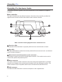
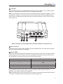
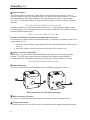
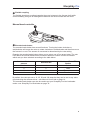
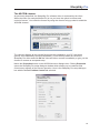
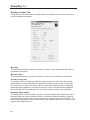
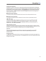
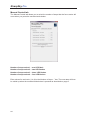
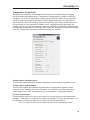
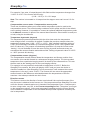
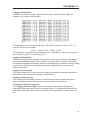
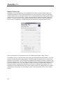
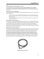
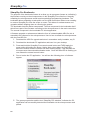
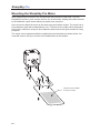
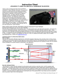
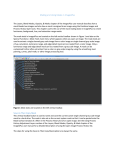
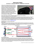
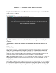
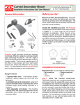
SharpSky Pro digital focuser and dew control system user manual V1.1 SharpSky Pro Contents Introduction ...........................................................................................................4 SharpSky Pro Driver Installation..........................................................................5 SharpSky Pro Hardware Guide.............................................................................6 Main controller . ............................................................................................................................6 Motor enclosure.............................................................................................................................8 Manual hand controller..................................................................................................................9 SharpSky Pro Software Guide............................................................................10 ASCOM, Drivers, Clients.............................................................................................................10 The ASCOM chooser.................................................................................................................. 11 Position Control Tab....................................................................................................................12 Manual Control tab......................................................................................................................14 Temperature Control tab..............................................................................................................15 Heater Control tab.......................................................................................................................18 SharpSky Pro Bootloader............................................................................................................20 Mounting the SharpSky Pro Motor.....................................................................22 SharpSky Pro Change Record Date Version Author Reason for change 1/1/2013 1.0 D. Trewren Initial version 1/3/2013 1.1 M. O’Neill Review and edit SharpSky Pro Introduction Thank you for purchasing the SharpSky Pro digital focus and dew control system. The purpose of the product to is provide an ASCOM-compliant digital telescope focusing solution combined with a four channel dew controller. The product is designed to be robust and rugged while at the same time look stylish and in keeping with the type of equipment many modern astro-photographers are using in the field. SharpSky Pro consists of three main components. The most tangible component is the physical hardware, (i.e. the main controller, motor enclosure etc.). The second and equally important component is the ASCOM software driver (available for download at www.sharpsky.net/). The software driver provides the interface between the standardised ASCOM platform and the physical hardware. The third component is the embedded firmware running on the microprocessor which is housed in the controller enclosure. Both the ASCOM driver and the embedded firmware can be updated by the user should future enhancements be produced. Components supplied : • SharpSky Pro digital focus and dew main control box • Motor enclosure and temperature sensor • Motor enclosure fitting bracket • Manual control box • Motor connection lead • USB connection lead • 12V power connection lead (fused) • Optional temperature probe SharpSky Pro SharpSky Pro Driver Installation Correct driver installation is critical to the correct operation of the focuser under PC control. You must install the driver before connecting the hardware to the PC. Before installing the driver, you must install the latest ASCOM 6SP1 platform. This is especially important if your PC is running a 64-bit operating system. Driver installation is as follows : • Before installing the driver ensure all ASCOM clients (Maxim DL, ImagesPlus etc.) applications are closed. This is especially important if you are updating a currently installed driver with a newer version. • If a previous SharpSky Pro driver is installed, uninstall it using the add/remove programs option in the Windows control panel before installing the new driver. Once again, ensure all ASCOM clients are closed. • Download the SharpSky Pro driver installer “SharpSkyProSetup.exe” from the website (www.sharpsky.net/) then run it by double clicking it. • Follow the simple on-screen instructions. Once the driver software is installed, connect your SharpSky Pro hardware to a PC USB port and connect the 12V power connector to a 12V DC power supply (note that the centre pin is positive). The very first time the controller is connected to the PC or to a new USB port there might be a small delay while Windows detects your SharpSky Pro as a new generic HID device. Once Windows has detected SharpSky Pro the red ‘Link’ LED will go out to indicate that the USB link has been established. SharpSky Pro SharpSky Pro Hardware Guide This section provides a guide to the main components of the SharpSky Pro supplied hardware. Main controller The main controller has two distinct functions. One side of the controller provides the digital focuser function and the other side the dew controller function. Rate Manual Direction Motor Link USB Main controller showing digital focuser connections etc. Direction LEDs The direction LEDs illuminate in sympathy with the focus motor direction of travel. Rate LED The Rate LED flashes to show the currently selected focus movement rate—see Manual hand controller on page 9. Manual hand control/temperature probe connector This socket is used to connect the manual hand controller. This socket is also used to connect the optional temperature probe. Motor connector The motor connector socket connects to the motor using the supplied lead. It provides signals to the stepper motor and returns information from the temperature sensor. The motor connector is pin compatible with focusers from MoonLite and RoboFocus. USB connector Provides the USB connection to the host computer via the supplied lead. SharpSky Pro y Link LED The Link LED shows the current USB connection status. By default, if the LED is ON the USB is not connected. If the LED is OFF, the USB is connected. Note: It is possible to reverse the way the Link LED works by using the software. You can, for example, configure it so that once the communication link has been established the LED comes on and therefore effectively acts as a power indicator—see Position Control tab on page 14. Power Select 4 3 12V 2 1 H1 H2 H3 H4 Main controller showing digital dew controller switches, connectors, etc. 12V connector Connect to your 12V DC power supply using the supplied lead. The centre pin is positive. Reverse polarity protection is provided. Power LEDs The four Power LEDs show the output power that has been set for the currently selected heater channel (H1-H4). Power levels are selected by moving the selector switch to the left. By default, the power levels are set to the following levels: Power LED Power level All off 0% 1 25% 2 50% 3 75% 4 100% It is possible to set the power levels to any percentage output required using the software—see Heater Control tab on page 18. Note: A flashing power LED shows either no heater is connected to the selected channel or that the connected heater is faulty and not consuming power. SharpSky Pro Selector switch The selector switch is a two-way switch with a centrally biased ‘off’ position. To use it, move the switch to the left or right then allow it to return to the central position. The switch has a dual function. Moving the switch to the right will select a heater output channel (H1 – H4). The selected channel is shown by its LED. Each movement selects a different channel: H1 > H2 > H3 > H4 > Off > H1 > H2 > H3 > etc. Moving the switch to the left will select a power level (1 – 4) for whichever heater output is currently active. The selected power level is shown by the Power LED. Each movement selects a different power level: Off > 1 > 2 > 3 > 4 > Off >1 > 2 > 3 > etc. Example: Selecting a dew heater and setting its power level. Let’s assume we want to select the dew heater that is connected to channel H3 and set its output power to 75%. 1. Move the selector switch to the right three times until the LED above heater output H3 is lit. 2. Move the switch to the left four times until Power LED number 4 is lit. Heater connectors and LEDs Connectors H1 to H4 provide standard RCA-type connections for four strap-type dew heaters. The LED above each connector indicates which heater output channel is currently selected. Channels are selected by moving the selector switch to the right. H1 > H2 > H3 > H4> H1 > H2 > H3 > etc. Motor enclosure The motor enclosure houses the stepper motor and digital temperature sensor. ro SharpSky P r Stepper Moto Temperature sensor Motor enclosure rear (left) and front (right) Main controller connector The motor is connected to the main controller connector using the supplied lead Temperature sensor The silver dome on the rear of the motor enclosure houses the digital temperature sensor. SharpSky Pro Flexible coupling The flexible aluminium coupling transmits the motor’s torque to the focuser shaft while accommodating a degree of misalignment between the focuser shaft and the motor. Manual hand controller Encoder/mode button The encoder/mode button has several functions. Turning the button clockwise or anticlockwise will cause the motor to rotate clockwise or anticlockwise and therefore move the focuser in or out. The amount of movement is determined by the rate setting. Pressing the encoder/mode button allows you to select one of four preset rates. The rate LED above the manual hand control connector flashes a number of times to indicate which rate you have selected according to the table below. Number of button presses 1 2 3 4 Selected rate 1 2 3 4 Number of Rate LED flashes Once Twice Three times Four times By default, the rates are set to 10, 25, 50 and 100 steps but they can be set to any value required using the software driver—see Manual Control tab on page 14. The encoder/mode button can also be used to put your SharpSky Pro into bootloader mode—see SharpSky Pro Bootloader on page 19. SharpSky Pro SharpSky Pro Software Guide This section provides information regarding the SharpSky Pro ASCOM compliant software driver. The driver is a piece of software that once installed is invoked by a client. I have found that sometimes, the concept of clients, drivers and ASCOM in general can be a little confusing for some. Therefore, as in introduction to the software section a short discussion and illustration is presented just to clarify the architecture and terminology. If you already know all about ASCOM or are not interested please feel free to skip the following introduction as it is for information and interest only. ASCOM A software platform that is designed to allow other pieces of software to communicate using a standardised message set or API (Application Programming Interface). DRIVER A piece of software that acts as an interface between the ASCOM API and the physical hardware. CLIENT A third-party piece of software which communicates with the driver via the ASCOM API. Such software clients are MaxIm DL, ImagesPlus, Sequence Generator Pro, etc. FIRMWARE Embedded software usually running on a microprocessor which forms the control centre for a piece of hardware such as a focuser, dome controller, etc. ASCOM, Drivers, Clients.... This all sounds complicated and you may ask yourself “Why bother with ASCOM? Why not just design the hardware and then design some dedicated software to control it?” The key to ASCOM is that it is a ‘standard’ and this is the beauty of using it. Using ASCOM, someone can design something like a focuser without the need to know anything about how the client works. They simply design a software driver which talks to their hardware and also talks to the standardised ASCOM API. Similarly, the client designer doesn’t need to know anything about the physical focuser hardware they simply design their client to talk to the ASCOM API. So, commands from the client are passed to the software driver via the ASCOM API. The driver interprets the commands and controls the hardware in the appropriate way. In a similar way messages are passed from the hardware to the software driver and on to the client via the ASCOM API. So how does the hardware on your telescope talk to the software driver which is running on your PC? At the heart of the hardware is a microprocessor running embedded software called firmware. The firmware communicates with the PC driver software via an interface. Historically, interfaces used to be serial RS232 but SharpSky Pro uses USB like most modern hardware. The microprocessor monitors the buttons and drives LEDs and motors. All the actions are turned into messages which are sent back and forth between the microprocessor and the PC driver over the USB link. 10 SharpSky Pro The ASCOM chooser As previously described, the SharpSky Pro software driver is accessed by the client. When the client (for example MaxIm DL) is run you have the option to choose and control a focuser. You select the focuser by using the client to bring up what is called the ‘ASCOM chooser’. The chooser displays all the current focuser drivers installed on your PC (and some generic ones installed by the ASCOM platform). From the drop down list, select the SharpSky Pro driver and click OK the client will either connect immediately or give you the chance to connect as a separate step. Notice the Properties button on the ASCOM chooser dialogue box. Clicking Properties opens the SharpSky Pro setup dialogue window which allows you to customise and control many aspects of the focuser operation. Here is the SharpSky Pro setup dialogue box with the default Position Control tab selected: 11 SharpSky Pro Position Control Tab The Position Control tab mainly controls aspects of hardware motor control, limits and some miscellaneous options. Max Step The maximum number of steps the focuser can travel. Travel beyond this point will be prevented by the driver. Max Increment The maximum number of steps the focuser can travel in one continuous movement. Period per step (ms) The period of time in milliseconds that the motor is driven for each step. This setting allows different motors with different mechanical properties to be driven. The general rule of thumb is to reduce this value until the motor starts missing steps or chattering. When this starts happening, increase the value by 10% for smooth but fast operation. Increasing the value by more than 10% will simply result in slower motor operation. Backlash adjust (steps) The SharpSky Pro motor contains a gearbox. All motor gearboxes exhibit some fixed backlash when the motor reverses direction. This field selects the number of steps to be introduced when the motor reverses direction in order to remove the backlash. The default value provides the best performance for the supplied motor but you may need to adjust it for a different motor. 12 SharpSky Pro Initial focuser position Irrespective of where the focuser is physically positioned this field allows the displayed absolute position to be set to any value required (between the Minimum focuser position and Maximum focuser position values). The field displays the current absolute position but if you enter a new value and press the set position button this will become the new absolution position. Note: the value cannot be changed if the motor is moving and a warning will be displayed. Minimum focuser position The minimum step value below which the focuser will not be permitted to travel. Maximum focuser position The maximum step value above which the focuser will not be permitted to travel. USB LED sense Clicking the Clear, off on connect checkbox inverts the way the USB status LED operates (from the default “LED off when USB connected” to “LED on when USB connected”). This effectively allows the USB status LED to be used as a power on indicator when the USB is connected. Client direction reverse Checking this feature reverses the motor direction sense with respect to way the client controls it. The motor direction might have to be reversed depending on which side of the focuser the motor is mounted or possibly due to the coupling mechanism. Versions These two fields show the current driver version being used and the current PIC microprocessor firmware version. The PIC version is read directly from the PIC microprocessor. Focuser connect The OK button connects the driver to the focuser hardware and causes setup data to be transferred to the PIC microprocessor. The Cancel button closes the window without any changes being made. 13 SharpSky Pro Manual Control tab The Manual Control tab allows you to select the number of steps that the focus motor will move when you press the encoder/mode button. Number of steps select 1 – one LED flash Number of steps select 2 – two LED flashes Number of steps select 3 – three LED flashes Number of steps select 4 – four LED flashes Enter values for each rate (1 to 4) in the Number of steps...” box. The new rates will then be called up when the encoder/mode button is pressed as described on page 9. 14 SharpSky Pro Temperature Control tab SharpSky Pro is capable of performing both temperature compensation and logging functions within the software driver. Temperature compensation is used to counteract changes in focus due to temperature changes of the telescope body. This is especially useful for large metal bodied telescopes found in Newtonian design. As temperature falls over the course of an imaging session the telescope will contract and therefore the focuser needs to move outward to maintain focus. Logging functions help profile the change of focal point with temperature in order to calculate the expansion coefficient and subsequently compensation functionality can counteract the effect of temperature change over time. Temperature sampling is performed every ten seconds. Compensation available yes/no This function informs the client whether temperature compensation is available or not. Compensation enable/disable This function enables and disables the temperature compensation algorithm which executes in the SharpSky Pro driver. Therefore, it is possible to perform temperature compensation even if the client doesn’t have a temperature compensation feature. Focuser steps/degree This parameter instructs the driver how much to move the focuser as the temperature changes. Temperature is calculated in degrees centigrade ºC to two decimal places. So the minimum movement in steps for any given entry of this parameter is : 0.01 x P (where P is the value entered in the Focuser steps/degree field) 15 SharpSky Pro For example, if we enter 10 steps/degree in this field and the temperature changes from 11.89°C to 10.27°C the focuser will move by: (11.89 – 10.27) x 10 = 16.2 steps Note: The number is truncated to 16 steps since the stepper motor can’t move 0.2 of a step. Compensation source motor / Compensation source probe These two checkboxes allow you to select which temperature probe is used as the compensation source. The motor housing contains a built-in probe and this is the default source setting. However, it is possible to connect an optional additional temperature probe to the Manual connector in place of the manual hand controller. Select which is used (one or both) using the checkboxes. Temperature hysteresis (degrees) The temperature hysteresis parameter tells the driver how much the temperature must change before a correction is applied. Consider the previous example where the temperature change was (11.89 – 10.27) = 1.62°C. With a default hysteresis setting of 0.50°C this would have resulted in a correction taking place (since 1.62 is greater than the 0.50 value set). The purpose of introducing hysteresis is to stop the focuser motor ‘hunting’. It is not desirable to have the motor moving by small increments every ten seconds as this causes vibration and achieves little. Setting a hysteresis value of 0.50ºC or 1.00ºC prevents this hunting. Compensation resume (degrees) The compensation resume feature allows the temperature and focuser position from one session to be carried forward to a subsequent imaging session. The last recorded temperature from a particular imaging session is stored by the software driver. This can then be used as the starting point for the new imaging session. For example, let’s say session A ended with a temperature of 4.20°C. Before the SharpSky Pro connects, the driver will display 4.20°C and you have the choice to check the enable box. After SharpSky Pro has connected, it will measure the current temperature. Let’s say it’s now 10.40°C. The focuser will now move the appropriate amount based on the difference calculated between the temperatures of the two sessions—the telescope should now be in focus. Direction reverse This feature reverses the direction of motor travel should it be required because of the way the motor is attached to the focuser etc. If the temperature drops SharpSky Pro must move the focuser outwards and move it inwards if the temperature rises. A simple test is to enter a large value, say 100, in the Focuser steps/degree field. Then place your finger on the temperature sensor. At the next temperature sampling point the focuser should move inwards to compensate for the simulated telescope tube expansion caused by the rise in temperature. 16 SharpSky Pro Logging enable/disable If enabled, this feature creates a log file of temperature, position and time/date. An example of the output is shown below: The steps/degree in this example was set to 100 and the hysteresis set to 0.50°C. To verify the test run top to bottom : ((27.81 – 14.62) x 100) + 25839 = 27158 The logging file is generated in the following format : SharpSky_templog_dd-mm-yyyy.txt and is output to your PC’s root directory (C:\). Logging enable/disable Temperature logging as described in the previous section can be enabled independently from the compensation feature. This is useful if you simply want to monitor temperature and position throughout the imaging session for profiling purposes without actually running compensation. Obviously, any position changes recorded will be as a result of user manual intervention. Logging timer/onchange This feature allows you to choose between logging temperature and position based on a periodic timer tick or based on a change in temperature. Logging period (seconds) If the Logging timer/onchange feature is checked this parameter specifies the period between logging events in seconds with a minimum period of 10 seconds. Temperature hysteresis (degrees) If the Logging timer/onchange feature is unchecked this parameter specifies the temperature hysteresis used to drive the logging feature. The temperature change must exceed this hysteresis value in order to generate an event that will be written to the log file. 17 SharpSky Pro Heater Control tab SharpSky Pro is equipped with a four channel dew heater controller. Rather than use traditional analogue rotary controls SharpSky Pro uses four preset values of output per channel which can be customised by the user. As shown below the default power output values are 25, 50, 75 and 100%. Simply use the sliders to preset the power output you require. On connection the values are transferred to the control box and remembered. Even if no PC connection is available the preset values last configured will be used. Here is the reason for the departure from the traditional analogue rotary control: Personally I have no real idea how much heat is generated by the dew heaters I use. The amount of heat delivered is dependent on the dew heater’s resistance, the surface area and many other factors. As a result with a traditional dew heater controller I tended to set the rotary control to 25, 50, 75 or 100% and leave it there. If the dew looked heavy I might turn it up a quarter turn or if it was lighter, I might turn it down a quarter turn. Basically, the rotary control is essentially redundant other than for adjustments of about 25%. So SharpSky Pro has dispensed with the rotary control in favour of a digital selection via the software driver still giving you percentage control over each preset value—best of both worlds. 18 SharpSky Pro Differential mode temperature control This mode allows you to control a single heater output by switching it on or off using the difference in temperature between the ambient temeprature and the temperature measured by the external probe to switch the heater on or off. Only heater output H1 has this feature. Differential mode enable/disable This checkbox enables or disables differential mode temperature control. If the differential mode is enabled: • The H1 heater connector LED will flash to show that you are in differential mode. Note: it may take a few seconds to start flashing once a temperature reading has been performed • The power level LED will be solid on if the heater is switched on or will flash if the heater is switched off Differential mode delta (degrees) Use this field to set the temperature difference (delta) required to switch the heater output H1. The ambient temperature is measured by the probe in the motor housing. The optional temperature probe can be mounted wherever you like to measure the temperature in a specific location. When the temperature recorded by the external probe exceeds the temperature recorded by the motor housing sensor by delta degrees the heater is switched off otherwise the heater is switched on. Differential mode offset (degrees) The sensor in the motor housing and the and external probe sensor are of a different type and may show slightly different absolute temperature values. The differential mode offset field is provided to align the two absolute readings. To calibrate them, allow the motor housing sensor and the external probe to settle by placing the external probe close to the motor housing and leaving them both for around ten minutes. Select each probe in turn and note any difference in temperature between them, enter the difference into the offset field. The field can be adjusted either positive or negative and is with reference to the motor housing sensor. For example, if the motor housing sensor reads 10.40 and the external probe reads 11.60 the offset should be set to -1.20 to align the two readings. External temperature probe 19 SharpSky Pro SharpSky Pro Bootloader The purpose of the bootloader feature is to allow you to reprogram (known as ‘reflashing’) the firmware running on the microprocessor in the SharpSky Pro control box. Normally reflashing the microprocessor would require specialised programming hardware. The bootloader allows reflashing to take place over the USB connection without even needing to remove SharpSky Pro from the scope or mount. This allows for enhancements and upgrades without stripping down or returning the product. The bootloader has two distinct components. The first component is the bootloader itself which forms part of the firmware executing on the microprocessor in the main control box. The second component is the bootloader PC client application. A firmware upgrade or enhancement takes the form of a downloadable HEX file, this is essentially the software for the microprocessor. Here is how to reflash the microprocessor with the new HEX file: 1. Download the HEX file upgrade and store it somewhere easily locatable, say C:\ 2. Download the bootloader PC application and save it on your desktop. 3. Press and hold the SharpSky Pro manual control button and THEN apply the power while still holding the button. Notice after a short delay the Rate LED above the manual control connector will start flashing rapidly – this indicates the microprocessor has entered bootloader mode. Once the Rate LED is flashing you can release the manual control button. 4. Run or invoke the PC application. You will see the following piece of software appear: 5. The green progress bar and the text “SharpSky PIC attached” indicates the PC application has successfully detected the bootloader on the microprocessor and paired. 20 SharpSky Pro 6. Click the 1. Open Hex file button and navigate to where you previously stored the downloaded HEX file. 7. Click the 2. Program/Verify button. 8. Once the Program/Verify is successful click the 3. Reset Device button. After a few seconds the new upgrade/enhancement will execute and SharpSky Pro will reconnect to the PC running its new firmware. The bootloader PC application can now be closed. 21 SharpSky Pro Mounting the SharpSky Pro Motor Most crayford-style focusers have a shaft fitted with a knob on either side. To fit the SharpSky Pro motor, you’ll need to remove one of the knobs. Usually the knobs are held to the shaft with a grub screw which just needs to be loosened. Once removed, attach the motor to the shaft using the flexible coupler. The motor has a 5mm diameter shaft with a flattened face on it. The end of the coupler which attaches to the focuser is drilled to accept a 3mm diameter shaft and has two grub screws for fixing purposes. The motor can be supported with the supplied two piece bracket as shown below. You must drill holes to suit your focuser in the shaded area of the bracket. This area can be drilled to suit your scope. 22 SharpSky Pro SharpSky Pro SharpSky Pro user manual_Rev 1.1_03/13 ©DaveTrewren 23