1
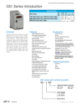
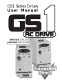
GS1 Series Drives
User Manual
115V Input: 0.25 - 0.5 hp
230V Input: 0.25 - 2.0 hp
WARNING Thank you for purchasing automation equipment from Automationdirect.com®, doing business as
AutomationDirect. We want your new automation equipment to operate safely. Anyone who installs
or uses this equipment should read this publication (and any other relevant publications) before
installing or operating the equipment.
To minimize the risk of potential safety problems, you should follow all applicable local and national
codes that regulate the installation and operation of your equipment. These codes vary from area to
area and usually change with time. It is your responsibility to determine which codes should be
followed, and to verify that the equipment, installation, and operation is in compliance with the
latest revision of these codes.
At a minimum, you should follow all applicable sections of the National Fire Code, National
Electrical Code, and the codes of the National Electrical Manufacturer's Association (NEMA). There
may be local regulatory or government offices that can also help determine which codes and
standards are necessary for safe installation and operation.
Equipment damage or serious injury to personnel can result from the failure to follow all applicable
codes and standards. We do not guarantee the products described in this publication are suitable for
your particular application, nor do we assume any responsibility for your product design,
installation, or operation.
Our products are not fault-tolerant and are not designed, manufactured or intended for use or resale
as on-line control equipment in hazardous environments requiring fail-safe performance, such as in
the operation of nuclear facilities, aircraft navigation or communication systems, air traffic control,
direct life support machines, or weapons systems, in which the failure of the product could lead
directly to death, personal injury, or severe physical or environmental damage ("High Risk
Activities"). AutomationDirect specifically disclaims any expressed or implied warranty of fitness for
High Risk Activities.
For additional warranty and safety information, see the Terms and Conditions section of our catalog.
If you have any questions concerning the installation or operation of this equipment, or if you need
additional information, please call us at 770-844-4200.
This publication is based on information that was available at the time it was printed. At
AutomationDirect we constantly strive to improve our products and services, so we reserve the right
to make changes to the products and/or publications at any time without notice and without any
obligation. This publication may also discuss features that may not be available in certain revisions
of the product.
Trademarks
This publication may contain references to products produced and/or offered by other companies.
The product and company names may be trademarked and are the sole property of their respective
owners. AutomationDirect disclaims any proprietary interest in the marks and names of others.
Copyright 2002, 2011, Automationdirect.com® Incorporated
All Rights Reserved
No part of this manual shall be copied, reproduced, or transmitted in any way without the prior,
written consent of Automationdirect.com® Incorporated. AutomationDirect retains the exclusive
rights to all information included in this document.
w–1
AVERTISSEMENT Nous vous remercions d'avoir acheté l'équipement d'automatisation de Automationdirect.com®, en
faisant des affaires comme AutomationDirect. Nous tenons à ce que votre nouvel équipement
d'automatisation fonctionne en toute sécurité. Toute personne qui installe ou utilise cet équipement
doit lire la présente publication (et toutes les autres publications pertinentes) avant de l'installer ou
de l'utiliser.
Afin de réduire au minimum le risque d'éventuels problèmes de sécurité, vous devez respecter tous
les codes locaux et nationaux applicables régissant l'installation et le fonctionnement de votre
équipement. Ces codes diffèrent d'une région à l'autre et, habituellement, évoluent au fil du temps. Il
vous incombe de déterminer les codes à respecter et de vous assurer que l'équipement, l'installation
et le fonctionnement sont conformes aux exigences de la version la plus récente de ces codes.
Vous devez, à tout le moins, respecter toutes les sections applicables du Code national de
prévention des incendies, du Code national de l'électricité et des codes de la National Electrical
Manufacturer's Association (NEMA). Des organismes de réglementation ou des services
gouvernementaux locaux peuvent également vous aider à déterminer les codes ainsi que les normes
à respecter pour assurer une installation et un fonctionnement sûrs.
L'omission de respecter la totalité des codes et des normes applicables peut entraîner des dommages
à l'équipement ou causer de graves blessures au personnel. Nous ne garantissons pas que les produits
décrits dans cette publication conviennent à votre application particulière et nous n'assumons aucune
responsabilité à l'égard de la conception, de l'installation ou du fonctionnement de votre produit.
Nos produits ne sont pas insensibles aux défaillances et ne sont ni conçus ni fabriqués pour
l'utilisation ou la revente en tant qu'équipement de commande en ligne dans des environnements
dangereux nécessitant une sécurité absolue, par exemple, l'exploitation d'installations nucléaires, les
systèmes de navigation aérienne ou de communication, le contrôle de la circulation aérienne, les
équipements de survie ou les systèmes d'armes, pour lesquels la défaillance du produit peut
provoquer la mort, des blessures corporelles ou de graves dommages matériels ou
environnementaux («activités à risque élevé»). La société AutomationDirect nie toute garantie
expresse ou implicite d'aptitude à l'emploi en ce qui a trait aux activités à risque élevé.
Pour des renseignements additionnels touchant la garantie et la sécurité, veuillez consulter la section
Modalités et conditions de notre documentation. Si vous avez des questions au sujet de l'installation
ou du fonctionnement de cet équipement, ou encore si vous avez besoin de renseignements
supplémentaires, n'hésitez pas à nous téléphoner au 770-844-4200.
Cette publication s'appuie sur l'information qui était disponible au moment de l'impression. À la
société AutomationDirect, nous nous efforçons constamment d'améliorer nos produits et services.
C'est pourquoi nous nous réservons le droit d'apporter des modifications aux produits ou aux
publications en tout temps, sans préavis ni quelque obligation que ce soit. La présente publication
peut aussi porter sur des caractéristiques susceptibles de ne pas être offertes dans certaines versions
révisées du produit.
Marques de commerce
La présente publication peut contenir des références à des produits fabriqués ou offerts par d'autres
entreprises. Les désignations des produits et des entreprises peuvent être des marques de commerce
et appartiennent exclusivement à leurs propriétaires respectifs. AutomationDirect nie tout intérêt
dans les autres marques et désignations.
Copyright 2002, 2011, Automationdirect.com® Incorporated
Tous droits réservés
Nulle partie de ce manuel ne doit être copiée, reproduite ou transmise de quelque façon que ce soit
sans le consentement préalable écrit de la société Automationdirect.com® Incorporated.
AutomationDirect conserve les droits exclusifs à l'égard de tous les renseignements contenus dans le
présent document.
WARNING WARNING: Read this manual thoroughly before using GS1 Series AC Motor Drives.
WARNING: AC input power must be disconnected before performing any maintenance.
Do not connect or disconnect wires or connectors while power is applied to the
circuit. Maintenance must be performed only by a qualified technician.
WARNING: There are highly sensitive MOS components on the printed circuit boards,
and these components are especially sensitive to static electricity. To avoid damage to
these components, do not touch these components or the circuit boards with metal
objects or your bare hands.
WARNING: A charge may still remain in the DC-link capacitor with hazardous
voltages, even if the power has been turned off. To avoid personal injury, do not
remove the cover of the AC drive until all "DISPLAY LED" lights on the digital keypad
are off. Please note that there are live components exposed within the AC drive. Do
not touch these live parts.
WARNING: Ground the GS1 AC Drive using the ground terminal. The grounding
method must comply with the laws of the country where the AC drive is to be
installed. Refer to “Basic Wiring Diagram” in CHAPTER 2.
WARNING: The mounting enclosure of the AC drive must comply with EN50178. Live
parts shall be arranged in enclosures or located behind barriers that meet at least the
requirements of the Protective Type IP20. The top surface of the enclosures or barrier
that is easily accessible shall meet at least the requirements of the Protective Type
IP40. Users must provide this environment for GS1 Series AC Drive.
WARNING: The AC drive may be destroyed beyond repair if incorrect cables are
connected to the input/output terminals. Never connect the AC drive output
terminals T1, T2, and T3 directly to the AC main circuit power supply.
w–3
GS1 SERIES AC DRIVE
USER MANUAL
Please include the Manual Number and the Manual Issue, both shown below, when
communicating with Technical Support regarding this publication.
Manual Number:
GS1-M
Issue:
Second Edition
Issue Date:
July, 2011
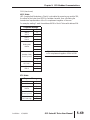
Publication History
Issue
Date
Description of Changes
First Edition
06/07/2002 Original
Numerous changes throughout; especially:
Ch2 (Installation and Wiring) – storage conditions and circuit protection
Ch4 (AC Drive Parameters) – parameter descriptions and explanations
Ch5 (GS1 Modbus Communications) – PLC connections, programming, and
Second Edition 07/06/2011
communications delays
Ch6 (Maintenance and Troubleshooting) – recharge capacitors
AppxA (Accessories) – new accessories
AppxB (Using GS1 AC Drives with AutomationDirect PLCs) – CLICK PLCs
TABLE OF CONTENTS
Chapter 1: Getting Started . . . . . . . . . . . . . . . . . . .1–1
Manual Overview . . . . . . . . . . . . . . . . . . . . . . . . . . . . . . . . . .1–2
Overview of this Publication . . . . . . . . . . . . . . . . . . . . . . . . . . . . . .1–2
Who Should Read This Manual . . . . . . . . . . . . . . . . . . . . . . . . . . . .1–2
Supplemental Publications . . . . . . . . . . . . . . . . . . . . . . . . . . . . . . .1–2
Technical Support . . . . . . . . . . . . . . . . . . . . . . . . . . . . . . . . . . . . . .1–2
Special Symbols . . . . . . . . . . . . . . . . . . . . . . . . . . . . . . . . . . . . . . .1–2
GS1 AC Drive Introduction . . . . . . . . . . . . . . . . . . . . . . . . . . .1–3
Purpose of AC Drives . . . . . . . . . . . . . . . . . . . . . . . . . . . . . . . . . . .1–3
Drive Package Contents . . . . . . . . . . . . . . . . . . . . . . . . . . . . . . . . .1–3
Nameplate Information . . . . . . . . . . . . . . . . . . . . . . . . . . . . . . . . . .1–3
Model Explanation . . . . . . . . . . . . . . . . . . . . . . . . . . . . . . . . . . . . .1–3
External Parts and Labels . . . . . . . . . . . . . . . . . . . . . . . . . . . . . . . . .1–4
GS1 AC Drive Specifications . . . . . . . . . . . . . . . . . . . . . . . . . .1–5
(Table of Contents continued next page)
Table of Contents
Chapter 2: Installation and Wiring . . . . . . . . . . . . . .2–1
Ambient Conditions . . . . . . . . . . . . . . . . . . . . . . . . . . . . . . . .2–2
Storage Conditions . . . . . . . . . . . . . . . . . . . . . . . . . . . . . . . . .2–2
Installation . . . . . . . . . . . . . . . . . . . . . . . . . . . . . . . . . . . . . . .2–3
Minimum Clearances and Air Flow . . . . . . . . . . . . . . . . . . . . . . . . .2–3
GS1 AC Drive Dimensions . . . . . . . . . . . . . . . . . . . . . . . . . . . .2–4
GS1 Circuit Connections . . . . . . . . . . . . . . . . . . . . . . . . . . . . .2–5
Danger! . . . . . . . . . . . . . . . . . . . . . . . . . . . . . . . . . . . . . . . . . .2–5
Wiring Notes: PLEASE READ PRIOR TO INSTALLATION. . . . . . . . . . .2–5
Motor Operation Precautions . . . . . . . . . . . . . . . . . . . . . . . . . . . . .2–6
Short Circuit Withstand . . . . . . . . . . . . . . . . . . . . . . . . . . . . . . . . . .2–6
Applicable Codes . . . . . . . . . . . . . . . . . . . . . . . . . . . . . . . . . . . . . .2–7
Circuit Protection Devices . . . . . . . . . . . . . . . . . . . . . . . . . . . .2–7
Maximum Recommended Circuit Protection Devices . . . . . . . . . . .2–7
Main Circuit Wiring . . . . . . . . . . . . . . . . . . . . . . . . . . . . . . . . .2–8
Input Power Connections . . . . . . . . . . . . . . . . . . . . . . . . . . . . . . . .2–9
Output Power Connections . . . . . . . . . . . . . . . . . . . . . . . . . . . . . .2–10
Control Terminal Wiring . . . . . . . . . . . . . . . . . . . . . . . . . . . . . . . .2–11
Basic Wiring Diagram . . . . . . . . . . . . . . . . . . . . . . . . . . . . . . . . . .2–12
External Wiring and Accessories . . . . . . . . . . . . . . . . . . . . . . . . . .2–13
(Table of Contents continued next page)
ii
GS1 Series AC Drive User Manual
2nd Edition
07/06/2011
Table of Contents
Chapter 3: Keypad Operation and Quickstart . . . . .3–1
The GS1 Digital Keypad . . . . . . . . . . . . . . . . . . . . . . . . . . . . .3–2
LED Display . . . . . . . . . . . . . . . . . . . . . . . . . . . . . . . . . . . . . . . . . . .3–2
Function Keys . . . . . . . . . . . . . . . . . . . . . . . . . . . . . . . . . . . . . . . . .3–2
Displaying the Status of the GS1 AC Drive . . . . . . . . . . . . . . . . . . .3–3
Programming the GS1 AC Drive . . . . . . . . . . . . . . . . . . . . . . . . . . .3–4
GS1 Quickstart . . . . . . . . . . . . . . . . . . . . . . . . . . . . . . . . . . . .3–5
Example 1: Constant torque (e.g. conveyors, compressors, etc.) . .3–5
Example 2: Variable torque (e.g. fans, centrifugal pumps, etc.) . . .3–9
Chapter 4: AC Drive Parameters . . . . . . . . . . . . . . .4–1
GS1 Parameter Summary . . . . . . . . . . . . . . . . . . . . . . . . . . . .4–2
Detailed Parameter Listings . . . . . . . . . . . . . . . . . . . . . . . . . . .4–9
Motor Parameters . . . . . . . . . . . . . . . . . . . . . . . . . . . . . . . . . . . . . .4–9
Ramp Parameters . . . . . . . . . . . . . . . . . . . . . . . . . . . . . . . . . . . . .4–11
Volts/Hertz Parameters . . . . . . . . . . . . . . . . . . . . . . . . . . . . . . . . .4–17
Digital Parameters . . . . . . . . . . . . . . . . . . . . . . . . . . . . . . . . . . . . .4–20
Analog Parameters . . . . . . . . . . . . . . . . . . . . . . . . . . . . . . . . . . . .4–29
Presets Parameters . . . . . . . . . . . . . . . . . . . . . . . . . . . . . . . . . . . .4–38
Protection Parameters . . . . . . . . . . . . . . . . . . . . . . . . . . . . . . . . . .4–39
Display Parameters . . . . . . . . . . . . . . . . . . . . . . . . . . . . . . . . . . . .4–47
Communication Parameters . . . . . . . . . . . . . . . . . . . . . . . . . . . . .4–48
(Table of Contents continued next page)
2nd Edition
07/06/2011
GS1 Series AC Drive User Manual
iii
Table of Contents
Chapter 5: GS1 Modbus Communications . . . . . . .5–1
Communication Parameters Summary . . . . . . . . . . . . . . . . . .5–2
GS1 Parameter Memory Addresses . . . . . . . . . . . . . . . . . . . . .5–4
GS1 Status Addresses . . . . . . . . . . . . . . . . . . . . . . . . . . . . . . .5–8
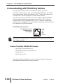
Communicating with AutomationDirect PLCs . . . . . . . . . . . .5–11
Step
Step
Step
Step
1:
2:
3:
4:
Choose the Appropriate CPU . . . . . . . . . . . . . . . . . . . . . .5–11
Make the Connections . . . . . . . . . . . . . . . . . . . . . . . . . . .5–11
Set AC Drive Parameters . . . . . . . . . . . . . . . . . . . . . . . . .5–16
Configure the PLC CPU . . . . . . . . . . . . . . . . . . . . . . . . . .5–16
CLICK Modbus Ladder Programming . . . . . . . . . . . . . . . . . .5–20
Separate Run Command Write Instruction . . . . . . . . . . . . . . . . . .5–20
Block Transfer Parameters for Modbus Programs . . . . . . . . . . . . . .5–20
CLICK Communication Program – (for CLICK PLCs) . . . . . . . . . . .5–21
DirectLOGIC Modbus Ladder Programming . . . . . . . . . . . . .5–35
Separate Run Command Write Instruction . . . . . . . . . . . . . . . . . .5–35
Block Transfer Parameters for Modbus Programs . . . . . . . . . . . . . .5–35
DirectLOGIC Basic Communication Program
– start with this code . . . . . . . . . . . . . . . . . . . . . . . . . . . . . . . . . .5–36
Programming Differences for DirectLOGIC PLCs . . . . . . . . . . . . . .5–37
DL MRX/MWX Communication Program
– for DL06 & D2-260 PLCs . . . . . . . . . . . . . . . . . . . . . . . . . . . . .5–38
DL RX/WX Communication Program
– for DL05, D2-250(-1), D4-450 . . . . . . . . . . . . . . . . . . . . . . . . .5–51
Communicating with Third-Party Devices . . . . . . . . . . . . . . .5–64
Common Third-Party MODBUS RTU Masters . . . . . . . . . . . . . . . .5–64
Using Modbus ASCII . . . . . . . . . . . . . . . . . . . . . . . . . . . . . . . . . . .5–65
Comm Delay – Optimizing Communications . . . . . . . . . . . .5–71
Optimizing Communications to GS Drives . . . . . . . . . . . . . . . . . .5–71
Types of Messages Sent to GS Drives . . . . . . . . . . . . . . . . . . . . . .5–72
Additional Message Delay Times . . . . . . . . . . . . . . . . . . . . . . . . . .5–73
Communication Delay Summary . . . . . . . . . . . . . . . . . . . . . . . . .5–75
(Table of Contents continued next page)
iv
GS1 Series AC Drive User Manual
2nd Edition
07/06/2011
Table of Contents
Chapter 6: Maintenance and Troubleshooting . . . . .6–1
Maintenance and Inspection . . . . . . . . . . . . . . . . . . . . . . . . . .6–2
Monthly Inspection: . . . . . . . . . . . . . . . . . . . . . . . . . . . . . . . . . . . .6–2
Annual Inspection . . . . . . . . . . . . . . . . . . . . . . . . . . . . . . . . . . . . . .6–2
Recharge Capacitors (for unused drives) . . . . . . . . . . . . . . . . . . . . .6–2
Troubleshooting . . . . . . . . . . . . . . . . . . . . . . . . . . . . . . . . . . .6–3
Fault Codes . . . . . . . . . . . . . . . . . . . . . . . . . . . . . . . . . . . . . . . . . . .6–3
Warning Messages . . . . . . . . . . . . . . . . . . . . . . . . . . . . . . . . . . . . .6–5
Appendix A: Accessories . . . . . . . . . . . . . . . . . . . . .A–1
Accessories Part Numbering . . . . . . . . . . . . . . . . . . . . . . . . . .A–2
Line Reactors . . . . . . . . . . . . . . . . . . . . . . . . . . . . . . . . . . . . . .A–2
Line Reactors – LR Series . . . . . . . . . . . . . . . . . . . . . . . . . . . . . . . . .A–3
Line Reactors – Legacy GS Series (do not use for new installations) A–4
Line Reactor Dimensions – LR Series . . . . . . . . . . . . . . . . . . . . . . . .A–5
Line Reactor Dimensions – Legacy GS Series (not for new installations)
. . . . . . . . . . . . . . . . . . . . . . . . . . . . . . . . . . . . . . . . . . . . . . . . . . . .A–8
Line Reactor Applications and Connections . . . . . . . . . . . . . . . . . . .A–9
RF Filter . . . . . . . . . . . . . . . . . . . . . . . . . . . . . . . . . . . . . . . . .A–12
RF Filter Dimensions . . . . . . . . . . . . . . . . . . . . . . . . . . . . . . . . . . .A–12
RF Filter Wiring . . . . . . . . . . . . . . . . . . . . . . . . . . . . . . . . . . . . . . .A–12
Fuses and Fuse Kits . . . . . . . . . . . . . . . . . . . . . . . . . . . . . . . .A–13
Fuse Block Dimensions . . . . . . . . . . . . . . . . . . . . . . . . . . . . . . . . .A–13
Ethernet Interface . . . . . . . . . . . . . . . . . . . . . . . . . . . . . . . . .A–14
ZIPLink™ Cables for RS-485 Modbus RTU . . . . . . . . . . . . . . .A–15
GS Drive Configuration Software . . . . . . . . . . . . . . . . . . . . .A–16
System Requirements . . . . . . . . . . . . . . . . . . . . . . . . . . . . . . . . . .A–16
Configuration Cable . . . . . . . . . . . . . . . . . . . . . . . . . . . . . . . . . . .A–16
(Table of Contents continued next page)
2nd Edition
07/06/2011
GS1 Series AC Drive User Manual
v
Table of Contents
Appendix B: Using GS1 AC Drives with
AutomationDirect PLCs . . . . . . . . . . . . . . . . . . . . . .B–1
Compatible AutomationDirect PLCs and Modules . . . . . . . . . .B–2
Typical PLC Connections to GS1 Series AC Drives . . . . . . . . . .B–6
CLICK CPU and DC Output Modules (Sinking) . . . . . . . . . . . . . . . .B–6
CLICK CPU Modules with Non-isolated Analog Outputs . . . . . . . . .B–7
DirectLOGIC DC Output Modules (Sinking) . . . . . . . . . . . . . . . . . .B–8
DirectLOGIC Isolated Analog Output Modules . . . . . . . . . . . . . . . .B–9
DirectLOGIC Non-isolated Voltage or Sourcing Current
Analog Output Modules . . . . . . . . . . . . . . . . . . . . . . . . . . . . . . .B–10
Index . . . . . . . . . . . . . . . . . . . . . . . . . . . . . . . . . . . . .I–1
vi
GS1 Series AC Drive User Manual
2nd Edition
07/06/2011
GETTING STARTED
CHAPTER
1
Contents of this Chapter...
Manual Overview . . . . . . . . . . . . . . . . . . . . . . . . . . . . . . . . . . . . .1–2
Overview of this Publication . . . . . . . . . . . . . . . . . . . . . . . . . . . . . . . . . .1–2
Who Should Read This Manual . . . . . . . . . . . . . . . . . . . . . . . . . . . . . . .1–2
Supplemental Publications . . . . . . . . . . . . . . . . . . . . . . . . . . . . . . . . . . .1–2
Technical Support . . . . . . . . . . . . . . . . . . . . . . . . . . . . . . . . . . . . . . . . .1–2
Special Symbols . . . . . . . . . . . . . . . . . . . . . . . . . . . . . . . . . . . . . . . . . . .1–2
GS1 AC Drive Introduction . . . . . . . . . . . . . . . . . . . . . . . . . . . . . .1–3
Purpose of AC Drives . . . . . . . . . . . . . . . . . . . . . . . . . . . . . . . . . . . . . . .1–3
Drive Package Contents . . . . . . . . . . . . . . . . . . . . . . . . . . . . . . . . . . . . .1–3
Nameplate Information . . . . . . . . . . . . . . . . . . . . . . . . . . . . . . . . . . . . .1–3
Model Explanation . . . . . . . . . . . . . . . . . . . . . . . . . . . . . . . . . . . . . . . . .1–3
External Parts and Labels . . . . . . . . . . . . . . . . . . . . . . . . . . . . . . . . . . . .1–4
GS1 AC Drive Specifications . . . . . . . . . . . . . . . . . . . . . . . . . . . . .1–5
Chapter 1: Getting Started
Manual Overview
Overview of this Publication
The GS1 AC Drive User Manual describes the installation, configuration, and
methods of operation of the GS1 Series AC Drive.
Who Should Read This Manual
This manual contains important information for those who will install, maintain,
and/or operate any of the GS1 Series AC Drives.
Supplemental Publications
The National Electrical Manufacturers Association (NEMA) publishes many
different documents that discuss standards for industrial control equipment.
Global Engineering Documents handles the sale of NEMA documents. For more
information, you can contact Global Engineering Documents at:
15 Inverness Way East
Englewood, CO 80112-5776
1-800-854-7179 (within the U.S.)
303-397-7956 (international)
www.global.ihs.com
NEMA documents that might assist with your AC drive systems are:
• Application Guide for AC Adjustable Speed Drive Systems
• Safety Standards for Construction and Guide for Selection, Installation, and
Operation of Adjustable Speed Drive Systems.
Technical Support
By Telephone: 770-844-4200
(Mon.-Fri., 9:00 a.m.-6:00 p.m. E.T.)
On the Web: www.automationdirect.com
Our technical support group is glad to work with you in answering your questions.
If you cannot find the solution to your particular application, or, if for any reason
you need additional technical assistance, please call technical support at
770-844-4200. We are available weekdays from 9:00 a.m. to 6:00 p.m. Eastern
Time.
We also encourage you to visit our web site where you can find technical and
non-technical information about our products and our company. Visit us at
www.automationdirect.com.
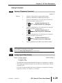
Special Symbols
When you see the “notepad” icon in the left-hand margin, the paragraph to its
immediate right will be a special note.
When you see the “exclamation mark” icon in the left-hand margin, the paragraph to
its immediate right will be a WARNING. This information could prevent injury, loss
of property, or even death (in extreme cases).
1–2
GS1 Series AC Drive User Manual
2nd Edition
07/06/2011
Chapter 1: Getting Started
GS1 AC Drive Introduction
Purpose of AC Drives
AC drives are generally known by many different names: Adjustable Frequency
Drives (AFD), Variable Frequency Drives (VFD), and Inverters. Drives are used
primarily to vary the speed of three phase AC induction motors, and they also
provide non-emergency start and stop control, acceleration and deceleration, and
overload protection. By gradually accelerating the motor, drives can reduce the
amount of motor startup inrush current.
AC drives function by converting incoming AC power to DC, which is then
synthesized back into three phase output power. The voltage and frequency of
this synthesized output power is directly varied by the drive, where the frequency
determines the speed of the three phase AC induction motor.
Drive Package Contents
After receiving the AC motor drive, please check for the following:
• Make sure that the package includes an AC drive, the GS1 Series AC Drive User
Manual, and the GS1 Series AC Drive Quick Reference.
• Inspect the unit to insure it was not damaged during shipment.
• Make sure that the part number indicated on the nameplate corresponds with the
part number of your order.
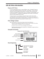
Nameplate Information
Example of 0.5 hp 115 VAC drive
AC Drive Model
Input Specification
Output Specification
Output Frequency Range
Barcode
Serial Number
Model Explanation
GS1 - 1 0P5
Applicable Motor Capacity
0P2: 1/4HP
1P0: 1HP
0P5: 1/2HP
2P0: 2HP
Input Voltage
1: 100–120VAC
2: 200–240VAC
Series Name
2nd Edition
07/06/2011
GS1 Series AC Drive User Manual
1–3
Chapter 1: Getting Started
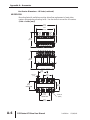
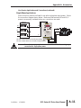
External Parts and Labels
�
�
�
� Digital Keypad
� Ventilation Slots
� Mounting Screw Holes
� Nameplate Label
� Input Power Terminals
�
�
� Control Input/Output Terminals
� Output Power Terminals
�
�
�
1–4
GS1 Series AC Drive User Manual
2nd Edition
07/06/2011
Chapter 1: Getting Started
GS1 AC Drive Specifications
115V Class
Model Name
Motor Rating
HP
kW
Rated Input Voltage
Maximum Output Voltage
Rated Input Current (A)
Rated Output Current (A)
Short Circuit Withstand
(A, rms symmetrical)
Watt Loss 100% I (W)
Weight (lb)
Dimensions (HxWxD)
GS1-10P2
GS1-10P5
1/4 hp
1/2 hp
0.2 kW
0.4 kW
Single-phase: 100–120 VAC ±10%, 50/60 Hz, ±5%
Three-phase: 200–240 VAC ( x2 of input voltage)
6
9
1.6
2.5
5kA @ 120 VAC
19.2
19.2
2.16
2.24
132.0 mm [5.20 in] x 68.0 mm [2.68 in] x 128.1 mm [5.04 in]
230V Class
Model Name
Motor Rating
GS1-20P2 GS1-20P5 GS1-21P0
HP
kW
Rated Input Voltage
Maximum Output Voltage
Rated Input Current (A)
Rated Output Current (A)
Short Circuit Withstand
(A, rms symmetrical)
Watt Loss 100% I (W)
Weight (lb)
Dimensions (HxWxD)
2nd Edition
07/06/2011
GS1-22P0
1/4 hp
1/2 hp
1 hp
2 hp
0.2 kW
0.4 kW
0.7 kW
1.5 kW
Single/three-phase:
Three-phase:
200–240 VAC ±10%, 50/60 Hz ±5% 200–240VAC ±10%, 50/60Hz ±5%
Three-phase: 200–240VAC (proportional to input voltage)
4.9/1.9
6.5/2.7
9.7/5.1
9
1.6
2.5
4.2
7.0
5kA @ 240 VAC
18.4
26.8
44.6
73
2.06
2.2
2.26
2.2
132.0 mm [5.20 in] x 68.0 mm [2.68 in] x 128.1 mm [5.04 in]
GS1 Series AC Drive User Manual
1–5
Chapter 1: Getting Started
General Specifications
Control Characteristics
Control System
Rated Output Frequency
Output Frequency Resolution
Overload Capacity
Torque Characteristics
Sinusoidal Pulse Width Modulation, carrier frequency 3–10 kHz
1.0 to 400.0 Hz
0.1 Hz
150% of rated current for 1 minute
Includes auto-slip compensation and starting torque 150% @ 5.0 Hz
Operation frequency: 0 to 60 Hz, 0–30% rated voltage.
Start time 0.0–5.0 seconds. Stop time 0.0–25.0 seconds
DC Braking
Acceleration/Deceleration Time 0.1 to 600 seconds (can be set individually)
Voltage/Frequency Pattern
V/F pattern adjustable. Settings available for
Constant Torque - low and high starting torque,
Variable Torque - low and high starting torque,
and user configured
Stall Prevention Level
20 to 200% or rated current
Operation Specifications
Keypad
Frequency
External
Setting
Signal
Potentiometer - 3 to 5kΩ, 0.5W; 0 to 10 VDC (input impedance
10 kΩ); 0 to 20 mA / 4 to 20 mA (input impedance 250Ω);
Multi-function inputs 3 and 4 (3 steps, JOG, UP/DOWN command);
RS-485 communication setting
Keypad
Operation
External
Setting
Signal
Setting by <RUN>, <STOP> buttons
Inputs
DI1, DI2, DI3, DI4 can be combined to offer various modes of
operation, RS-485 communication port
Digital
4 user-programmable: FWD/STOP, REV/STOP, RUN/STOP,
REV/FWD, RUN momentary (N.O.), STOP momentary (N.C.),
External Fault (N.O./N.C.), External Reset, Multi-Speed Bit
(1and 2), Jog, External Base Block (N.O./N.C.), Second Accel/Decel
Time, Speed Hold, Increase Speed, Decrease Speed, Reset Speed to
Zero, Input Disable
Analog
1 user-configurable, 10 bit resolution
0 to 10 VAC, (input impedance 10 kΩ),
0 to 20 mA, (input impedance 250Ω)
4 to 20 mA, (input impedance 250Ω)
Input
Terminals
Output
Digital
Terminals
1 user programmable: AC drive Running, AC drive Fault,
At Speed, Zero Speed, Above Desired Frequency (P 3-16), Below
Desired Frequency (P 3-16), At Maximum Speed,
Over-torque Detected, Above Desired Current (P3-17),
Below Desired Current (P 3-17)
Operating Functions
Automatic voltage regulation, S-curve, Over-voltage stall prevention,
DC braking, Fault records, Adjustable carried frequency, Starting
frequency setting of DC braking, Over-current stall prevention,
Momentary power loss restart, Reverse inhibition, Frequency limits,
Parameter lock/reset
Outputs
1–6
Setting by <UP> or <DOWN> buttons or potentiometer
GS1 Series AC Drive User Manual
2nd Edition
07/06/2011
Chapter 1: Getting Started
General Specifications (continued)
Protective Functions
Operator Devices
Programming
Operator
Interface
5-key, 4-digit, 7-segment LED, 4 status LEDs, potentiometer
Parameter values for setup and review, fault codes
Status Display
Master Frequency, Output Frequency, Scaled Output Frequency,
Output Voltage, DC Bus Voltage, Output Direction, Trip Event
Monitor, Trip History Monitor
Key Functions
RUN/STOP, DISPLAY/RESET, PROGRAM/ENTER, <UP>,
<DOWN>
Enclosure Rating
Ambient Temperature
Environment Ambient Humidity
Vibration
Installation Location
2nd Edition
Overcurrent, Overvoltage, Undervoltage, Electronic thermal
motor overload, Overheating, Overload, Self testing
07/06/2011
Protected chassis, IP20
-10° to 40°C (14°F to 104°F) w/o derating
0 to 90% RH (non-condensing)
9.8 m/s2(1G), less than 10 Hz; 5.88 m/s2 (0.6G) 20 to 50 Hz
Altitude 1000m or lower above sea level, keep from corrosive
gas, liquid and dust
GS1 Series AC Drive User Manual
1–7
Chapter 1: Getting Started
1–8
GS1 Series AC Drive User Manual
2nd Edition
07/06/2011
INSTALLATION
AND WIRING
CHAPTER
2
Contents of this Chapter...
Ambient Conditions . . . . . . . . . . . . . . . . . . . . . . . . . . . . . . . . . . .2–2
Storage Conditions . . . . . . . . . . . . . . . . . . . . . . . . . . . . . . . . . . . .2–2
Installation . . . . . . . . . . . . . . . . . . . . . . . . . . . . . . . . . . . . . . . . . . .2–3
Minimum Clearances and Air Flow . . . . . . . . . . . . . . . . . . . . . . . . . . . . .2–3
GS1 AC Drive Dimensions . . . . . . . . . . . . . . . . . . . . . . . . . . . . . . .2–4
GS1 Circuit Connections . . . . . . . . . . . . . . . . . . . . . . . . . . . . . . . .2–5
Danger! . . . . . . . . . . . . . . . . . . . . . . . . . . . . . . . . . . . . . . . . . . . . .2–5
Wiring Notes: PLEASE READ PRIOR TO INSTALLATION. . . . . . . . . . . . . .2–5
Motor Operation Precautions . . . . . . . . . . . . . . . . . . . . . . . . . . . . . . . . .2–6
Short Circuit Withstand . . . . . . . . . . . . . . . . . . . . . . . . . . . . . . . . . . . . .2–6
Applicable Codes . . . . . . . . . . . . . . . . . . . . . . . . . . . . . . . . . . . . . . . . . .2–7
Circuit Protection Devices . . . . . . . . . . . . . . . . . . . . . . . . . . . . . . .2–7
Maximum Recommended Circuit Protection Devices . . . . . . . . . . . . . . .2–7
Main Circuit Wiring . . . . . . . . . . . . . . . . . . . . . . . . . . . . . . . . . . . .2–8
Input Power Connections . . . . . . . . . . . . . . . . . . . . . . . . . . . . . . . . . . . .2–9
1-phase Input Power Connections . . . . . . . . . . . . . . . . . . . . . . . . . . . . . . . . . .2–9
3-phase Input Power Connections . . . . . . . . . . . . . . . . . . . . . . . . . . . . . . . . . .2–9
Output Power Connections . . . . . . . . . . . . . . . . . . . . . . . . . . . . . . . . .2–10
Control Terminal Wiring . . . . . . . . . . . . . . . . . . . . . . . . . . . . . . . . . . . .2–11
Basic Wiring Diagram . . . . . . . . . . . . . . . . . . . . . . . . . . . . . . . . . . . . . .2–12
External Wiring and Accessories . . . . . . . . . . . . . . . . . . . . . . . . . . . . . .2–13
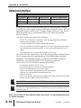
Chapter 2: Installation and Wiring
Ambient Conditions
Ambient environmental conditions for use:
Ambient Conditions
Ambient Temperature
Storage Temperature
Relative Humidity
Atmosphere Pressure
Vibration
-10° to 40°C (14°F to 104°F) w/o derating
-20° to 60 ° C (-4°F to 140°F) during short-term transportation period)
0 to 90% RH (non-condensing)
86 kPA to 106 kPA
9.8 m/s2(1G) @ less than 10 Hz; 5.88 m/s2 (0.6G) @ 10 to 50 Hz
Installation Location
Altitude 1000m or lower above sea level, keep from corrosive gas,
liquid and dust
Enclosure Rating
Protected chassis, IP20
Storage Conditions
GS1 AC drives should be kept in their shipping carton or crate until they are
installed. In order to retain their warranty coverage, they should be stored as
described below if they are not to be installed and used within three months.
• Store in a clean and dry location free from direct sunlight and corrosive fumes.
• For storage of longer than 3 months, store within an ambient temperature range of
-20 °C to 30 °C (-4°F to 86°F).
• For storage of 3 months or less, store within an ambient temperature range of
-20 °C to 60 °C (-4°F to 140°F).
• Store within a relative humidity range of 0% to 90% and non-condensing
environment.
• Store within an air pressure range of 86 kPA to 106 kPA.
• DO NOT store in an area with rapid changes in temperature.
(It may cause condensation and frost.)
• DO NOT place directly on the ground.
If the drive is stored or is otherwise unused for more than a year, the drive’s internal DC
link capacitors should be recharged before use. Otherwise, the capacitors may be
damaged when the drive starts to operate. We recommend recharging the capacitors
of any unused drive at least once per year. (Refer to Chapter 6, “Maintenance and
Troubleshooting” for information about recharging DC link capacitors.)
2–2
GS1 Series AC Drive User Manual
2nd Edition
07/06/2011
Chapter 2: Installation and Wiring
Installation
Install the AC drive in an enclosure that is specifically designed to house electrical
and electronic control equipment. Provide proper spacing within the enclosure to
allow the dissipation of heat produced by the drive and any other included
electrical and electronic equipment. Ventilation or air conditioning may also be
required, depending upon the application.
Improper installation of the AC drive will greatly reduce its life. Be sure to
observe the following precautions when selecting a mounting location:
• Do not mount the AC drive near heat-radiating elements or in direct sunlight.
• Do not install the AC drive in a place subjected to high temperature, high
humidity, excessive vibration, corrosive gases or liquids, or airborne dust or
metallic particles.
• Mount the AC drive vertically and do not restrict the air flow to the heat sink fins.
WARNING: Failure to observe these precautions may damage the drive and void the
warranty!
WARNING: AC drives generate a large amount of heat which may damage the AC
drive. Auxiliary cooling methods are typically required in order not to
exceed maximum ambient temperatures.
Minimum Clearances and Air Flow
Fan
6 in [150mm] min.
MAXIMUM AMBIENT TEMPERATURES
MUST NOT EXCEED 40°C (104°F)!
2 in
[50mm]
min.
2 in
[50mm]
min.
Air Flow
6 in
[150mm]
min.
Input
Power
2nd Edition
07/06/2011
To
Motor
GS1 Series AC Drive User Manual
2–3
Chapter 2: Installation and Wiring
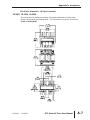
GS1 AC Drive Dimensions
68.0 (2.68)
)
20
56.0 (2.20)
.
dia
0.
0(
5.
STOP
RUN
FWD
REV
0
PROG
ENTER
100
132.0 (5.20)
RUN
STOP
120.0 (4.72)
DISPL
RESET
V
I
R1 R1O+ 10V AI DI1 DI2 DI3 DI4 CM
2–4
128.1 (5.04)
123.4 (4.86)
128.1 (5.04)
GS1 Series AC Drive User Manual
Unit: mm (in)
2nd Edition
07/06/2011
Chapter 2: Installation and Wiring
GS1 Circuit Connections
DANGER!
HAZARDOUS VOLTAGE!
Before making any connection to the AC drive, disconnect
all power to the AC drive, and wait five minutes for DC bus capacitors to discharge.
WARNING: Any electrical or mechanical modification to this equipment without prior
written consent of AutomationDirect.com Inc. will void all warranties, may result in a
safety hazard, and may void the UL listing.
Wiring Notes: PLEASE READ PRIOR TO INSTALLATION.
WARNING: Do not connect the AC input power to the T1, T2, and T3 output terminals.
This will damage the AC drive.
WARNING: Tighten all screws to the proper torque rating. See “Main Circuit Wiring”
later in this chapter.
1. During installation, follow all local electrical, construction, and safety codes for
the country in which the AC drive is to be installed.
2. Make sure the appropriate protective devices (circuit breaker or fuses) are
connected between the power supply and AC drive.
3. Make sure that the leads are connected correctly and the AC drive is properly
grounded.
4. Use ground leads that comply with AWG/MCM standards and keep them as
short as possible.
5. Use of contactors or disconnect switches for run/stop control of the AC drive
and motor will reduce the operating life cycle of the AC drive. Cycling a
power circuit switching device while the AC drive is in run mode should be
done only in emergency situations.
The installation of contactors or disconnects to isolate the motor during
maintenance, though permissible, is not recommended. Opening contactors or
disconnects while the drive is running will reduce the life cycle of the drive and
may immediately damage the inverter section of the drive!
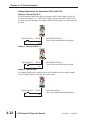
6. Multiple GS1 units can be installed in one location. All the units should be
grounded directly to a common ground terminal. The GS1 ground terminals
may also be connected in parallel, as shown in the figure below. Make sure
there are no ground loops.
Correct
Incorrect
Forward
running
2nd Edition
07/06/2011
GS1 Series AC Drive User Manual
2–5
Chapter 2: Installation and Wiring
7. When the AC drive output terminals T1, T2, and T3 are connected to the motor
terminals T1, T2, and T3, respectively, the motor will rotate counterclockwise
(as viewed from the shaft end of the motor) when a forward operation
command is received. To reverse the direction of motor rotation, switch the
connections of any of the two motor leads.
8. Make sure that the power source is capable of supplying the correct voltage
and required current to the AC drive.
9. Do not attach or remove wiring when power is applied to the AC drive.
10. Do not monitor the signals on the circuit board while the AC drive is in operation.
11. For single-phase, 115V class AC drives, AC power must be connected to
terminals L1 and L2. For the single-phase, 230V class AC drives, the AC
power can be connected to any two of the three input terminals L1, L2, or L3.
This AC drive is not intended for use with single-phase motors.
12. Route the power and control wires separately, or at 90 degree angle to each other.
13. When using a GFCI (Ground Fault Circuit Interrupt), select current sensor with sensitivity
of 200mA, and not less than 0.1-second detection to avoid nuisance tripping.
Motor Operation Precautions
1. When using the AC drive to operate a standard 3-phase induction motor, the
energy loss is greater than for an inverter duty motor.
2. Avoid running a standard induction motor at low speed, which may cause the
motor temperature to exceed the motor rating due to limited airflow produced
by the motor's fan.
3. When the standard motor operates at low speed, the output load must be decreased.
4. If 100% output torque is desired at low speed, it may be necessary to use a
special "inverter-duty" rated motor.
Short Circuit Withstand
Suitable for use on a circuit capable of delivering not more than 5,000 rms
symmetrical amperes. For all 115V models, the maximum is 120 Volts. For all
230V Models, the maximum is 240 Volts.
2–6
GS1 Series AC Drive User Manual
2nd Edition
07/06/2011
Chapter 2: Installation and Wiring
Applicable Codes
All GS1 Series AC drives are Underwriters Laboratories, Inc. (UL) and Canadian
Underwriters Laboratories (cUL) listed, and therefore comply with the
requirements of the National Electrical Code (NEC) and the Canadian Electrical
Code (CEC).
Installation intended to meet the UL and cUL requirements must follow the
instructions provided in "Wiring Notes" as a minimum standard. Follow all local
codes that exceed UL and cUL requirements. Refer to the technical data label
affixed to the AC drive and the motor nameplate for electrical data.
The "Fuses and Fuse Kits" section in Appendix A lists the recommended fuse part
number for each GS1 Series part number. These fuses (or equivalent) must be
used on all installations where compliance with U.L. standards is required.
Circuit Protection Devices
Short-circuit and ground-fault protection devices are essential to prevent costly
damage to your AC Drive. Fuse kits, which include fuses and fuse blocks, are
available from AutomationDirect for the GS1 Series AC Drives.
Maximum Recommended Circuit Protection Devices
The chart below gives the maximum recommended fuses and circuit breakers for
short-circuit and ground-fault protection of GS1 Series AC Drives. Fuses and
circuit breakers smaller than those shown are permitted.
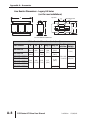
Maximum Recommended Circuit Protection Devices
Drive
Part #
V/HP/kW
Input
Phases
Input
Current
Time-Delay Fuse
Inverse-Time
Circuit Breaker
GS1-10P2
115 / 0.25 / 0.2
1
6A
20A type A3T (300V)
20A
GS1-10P5
115 / 0.5 / 0.4
1
9A
30A type A3T (300V)
30A
GS1-20P2
230 / 0.25 / 0.2
1
4.9A
15A type A3T (300V)
15A
3
1.9A
10A type A3T (300V)
10A
GS1-20P5
230 / 0.5 / 0.4
1
6.5A
25A type A3T (300V)
25A
3
2.7A
10A type A3T (300V)
10A
GS1-21P0
230 / 1 / 0.7
1
9.7A
45A type A3T (300V)
45A
3
5.1A
20A type A3T (300V)
20A
GS1-22P0
230 / 2 / 1.5
3
9.0A
25A type A3T (300V)
25A
Recommended fuses are required for UL applications, and the specific fuses are available as
shown in “Appendix A: Accessories”.
Recommended maximum fuses and circuit breakers are for protection of the AC drive.
They may or may not also provide required motor branch circuit protection, depending
upon the electrical code applicable to the installation.
2nd Edition
07/06/2011
GS1 Series AC Drive User Manual
2–7
Chapter 2: Installation and Wiring
Main Circuit Wiring
Main Circuit Terminals
Terminal
Description
L1, L2, L3 Input Power
T1, T2, T3 AC Drive Output
Ground
Main Circuit Wiring Specifications
AC Drive Model
GS1-10P2
GS1-10P5
GS1-20P2 (1-phase)
GS1-20P2 (3-phase)
GS1-20P5 (1-phase)
GS1-20P5 (3-phase)
GS1-21P0 (1-phase)
GS1-21P0 (3-phase)
GS1-22P0
Max. Current
(Input/Output)
Wire Gauge
Torque
12–16 AWG
5.5 kgf·cm
12–14 AWG
5.5 kgf·cm
6A / 1.6A
9A / 2.5A
4.9A / 1.6A
1.9A / 1.6A
6.5A / 2.5A
2.7A / 2.5A
9.7A / 4.2A
5.1A / 4.2A
9A / 7.0A
Wire Type: 75°C, copper only
2–8
GS1 Series AC Drive User Manual
2nd Edition
07/06/2011
Chapter 2: Installation and Wiring
Input Power Connections
1-phase Input Power Connections* **
L1 L2
1-phase Input Power*
115V Class**
230V Class**
Single-phase: 100–120VAC ±
10%, 50/60Hz, ±5%
Single-phase: 200–240VAC ±
10%, 50/60Hz ±5%
* Only models GS1-10P2, GS1-10P5,
GS1-20P2, GS1-20P5, and GS1-21P0
are rated for single-phase input power.
** For 115V class single phase drives,
AC power must be connected to terminals
L1 and L2.
For 230V class single phase drives,
AC power can be connected to any two of
the three terminals L1, L2 or L3.
GS1 Top View
3-phase Input Power Connections
L1 L2 L3
3-phase Input Power
GS1 Top View
2nd Edition
07/06/2011
230V Class
Three-phase: 200–240VAC
±10%, 50/60Hz ±5%
GS1 Series AC Drive User Manual
2–9
Chapter 2: Installation and Wiring
Output Power Connections
GS1 Bottom View
T1 T2 T3
Output Power
115V Class Max Output Voltage
230V Class Max Output Voltage
2–10
Three phase 200–240VAC (input voltage x2)
Three phase 200–240VAC (proportional to input voltage)
GS1 Series AC Drive User Manual
2nd Edition
07/06/2011
Chapter 2: Installation and Wiring
Control Terminal Wiring (Factory Settings)
GS1 Bottom View
Control Circuit Terminals
Terminal Symbol
R1
R1O
+10V
Description
AI
Analog Input
DI1
Digital Input 1
DI2
Digital Input 2
DI3
Digital Input 3
DI4
Digital Input 4
CM
Common
Remarks
Relay Output Common
120VAC/24VDC @5A,
Relay Output Normally Open 230VAC @2.5A
Internal Power Supply
+10VDC (10mA maximum load)
0 to +10 V (Max. Output Frequency) Input
0 to 20mA (Max. Output Frequency) Input
4 to 20mA (Max, Output Frequency) Input
Input voltage: Internally supplied (see Warning below)
Maximum ON Voltage: 6V
Minimum OFF Voltage: 11V
Minimum ON Current: 2.5 mA
Maximum OFF Current: 1mA
(See “Basic Wiring Diagram” on next page.)
Control Terminal Wire Range: 24–12 AWG
Control Terminal Tightening Torque: 5kgf·cm [4lbf·in]
Use twisted-shielded, twisted-pair or shielded-lead wires for the control signal wiring.
Run all signal wiring in a separate steel conduit. The shield wire should only be
connected at the AC drive. Do not connect shield wire on both ends.
WARNING: Do NOT connect external voltage sources to the Digital Inputs.
Permanent damage may result.
2nd Edition
07/06/2011
GS1 Series AC Drive User Manual
2–11
Chapter 2: Installation and Wiring
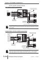
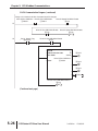
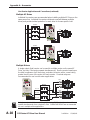
Basic Wiring Diagram
Users must connect wiring according to the circuit diagram shown below.
WARNING: Do not plug a modem or telephone into the GS1 RJ-12 Serial Comm Port,
or permanent damage may result. Terminals 1 and 2 must not be used as a power
source for your communication connection.
Power Source 3-phase*
100-120V±10%
(50/60Hz ±5%)
200-240V±10%
(50/60Hz±5%)
AC Motor
L1
L2
GS1-xxxx
T1
IM
T2
T3
L3
* Use terminals L1 and L2 for 115V, or
select any two of the power terminals
for 230V single-phase models
Grounding resistance
less than 0.1⏲
Forward/Stop
Reverse/Stop
External Fault (N.0)
DI1
R1O
Multi-function output contacts
120VAC/24VDC @5A
230VAC @2.5A
R1
Fault Indication
DI2
RJ-12 (6P6C)
DI3
6
1
DI4
Jog
Common Signal
Communication Port
CM
Analog voltage
0-10VDC
Potentiometer
3~5k⏲
Analog current
0-20mA; 4-20mA
RJ-12 Serial Comm Port
RS-485
1: +17V
2: GND
3: SG4: SG+
5: +5V
+10V 10mA
(max)
AI
CM
Factory default setting
Factory default source of frequency command is via the keypad potentiometer
Main circuit (power) terminals
2–12
Control circuit terminal
GS1 Series AC Drive User Manual
Shielded leads
2nd Edition
07/06/2011
Chapter 2: Installation and Wiring
External Wiring and Accessories
Warning: The installation of contactors or disconnects to isolate the motor during
maintenance, though permissible, is NOT recommended. Opening contactors or
disconnects while the drive is running will reduce the life cycle of the drive and may
immediately damage the inverter section of the drive!
Warning: We strongly recommend that you do NOT use a contactor between the AC
drive and the motor, unless there is an interlock to open the contactor when the drive
is not running.
1
Power Supply
From power supply
Please follow the specific power supply requirements
shown in CHAPTER 1.
Disconnect
Switch
2
Fuses
Input fuses protect the AC drive from excessive input
current due to line surges, short circuits, and ground
faults. They are recommended for all installations and
may be required for UL-listed installations.
Contactor (Optional)
3
Do NOT use a contactor or disconnect switch for
run/stop control of the AC drive and motor. This will
reduce the operating life cycle of the AC drive. Cycling
a power circuit switching device while the AC drive is in
run mode should be done only in emergency situations.
4
5
AC Line Reactor – Input Side (Optional)
L1
L2
L3
GS1-xxxx
AC Drive
T1
T2
T3
5
Input line reactors protect the AC drive from transient
overvoltage conditions typically caused by utility
capacitor switching, and reduce the available short circuit
current. Input line reactors also reduce harmonics
associated with AC drives, and are recommended for all
installations.
RF Filter (Optional)
RF filters reduce the radio frequency interference or noise
on the input or output side of the inverter.
AC Line Reactor – Output Side (Optional)
6
Motor
Motor grounding
terminal
Output line (load) reactors protect the motor insulation
against AC drive short circuits and IGBT reflective wave
damage, and also “smooth” the motor current waveform,
allowing the motor to run cooler. They are recommended
for operating “non-inverter-duty” motors, and when the
length of wiring between the AC drive and motor exceeds
75ft.
Please refer to APPENDIX A for specifications on GS1 AC Drive Accessories.
2nd Edition
07/06/2011
GS1 Series AC Drive User Manual
2–13
Chapter 2: Installation and Wiring
2–14
GS1 Series AC Drive User Manual
2nd Edition
07/06/2011
KEYPAD OPERATION
AND QUICKSTART
CHAPTER
3
Contents of this Chapter...
The GS1 Digital Keypad . . . . . . . . . . . . . . . . . . . . . . . . . . . . . . . .3–2
LED Display . . . . . . . . . . . . . . . . . . . . . . . . . . . . . . . . . . . . . . . . . . . . . .3–2
Function Keys . . . . . . . . . . . . . . . . . . . . . . . . . . . . . . . . . . . . . . . . . . . .3–2
Displaying the Status of the GS1 AC Drive . . . . . . . . . . . . . . . . . . . . . . .3–3
Programming the GS1 AC Drive . . . . . . . . . . . . . . . . . . . . . . . . . . . . . .3–4
GS1 Quickstart . . . . . . . . . . . . . . . . . . . . . . . . . . . . . . . . . . . . . . .3–5
Example 1: Constant torque
(e.g. conveyors, compressors, etc.) . . . . . . . . . . . . . . . . . . . . . . . . . . .3–5
Application Needs . . . . . . . . . . . . . . . . . . . . . . . . . . . . . . . . . . . . . . . . . . . . . .3–5
Parameter Setup . . . . . . . . . . . . . . . . . . . . . . . . . . . . . . . . . . . . . . . . . . . . . . . .3–6
Example 2: Variable torque
(e.g. fans, centrifugal pumps, etc.) . . . . . . . . . . . . . . . . . . . . . . . . . . .3–9
Application Needs . . . . . . . . . . . . . . . . . . . . . . . . . . . . . . . . . . . . . . . . . . . . . .3–9
Parameter Setup . . . . . . . . . . . . . . . . . . . . . . . . . . . . . . . . . . . . . . . . . . . . . . . .3–9
Chapter 3: Keypad Operation and Quickstart
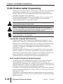
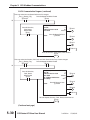
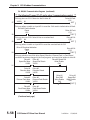
The GS1 Digital Keypad
The digital keypad includes a 4-digit LED display, 4 LED indicators, 5 function
keys, and a potentiometer. The diagram below shows all of the features of the
digital keypad and an overview of their functions.
LED Display with
RUN, FWD, REV, &
STOP Indicators
Down Key
Display/Reset Key
Up Key
Program/Enter Key
Potentiometer
RUN/STOP Key
LED Display
The LED Display shows the operation values and parameter settings of the AC drive.
The display also has four LED Indicators that show the RUN, STOP, FWD, and REV
status of the AC drive.
Function Keys
Program/Enter Key
Press the PROGRAM/ENTER key to view parameters and store parameter settings.
Display/Reset Key
Press the DISPL/RESET key to cycle through the operational values (Status Display)
of the AC drive. This key will also reset the AC drive when a fault has occurred.
Run/Stop Key
Press the RUN/STOP key to start or stop the AC drive operation.
Up/Down Keys
Press the UP/DOWN keys to scroll through the parameter set or to change
parameter settings. Press the “Up” or “Down” key momentarily to change the
parameter settings in single-unit increments. To quickly run through the range of
settings, press and hold the “Up” or “Down” key.
Potentiometer
The potentiometer is used to set the AC drive operation frequency.
3–2
GS1 Series AC Drive User Manual
2nd Edition
07/06/2011
Chapter 3: Keypad Operation and Quickstart
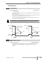
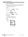
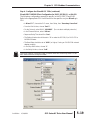
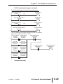
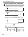
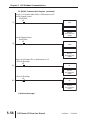
Displaying the Status of the GS1 AC Drive
Press the DISPL/RESET button on the keypad repeatedly to cycle through the status
messages on the AC drive. The diagram below shows the order of the status
messages and their definitions. The status of the AC drive can be shown in RUN
or STOP mode.
00
X60.0
01
!750
02
90.0
03
A 0.9
04
o!8.0
05
U230
06
d328
07
F60.0
2nd Edition
07/06/2011
00 Actual Operating Frequency
Displays the actual operating frequency present at the
T1, T2, and T3 terminals. Example: 60.0Hz
01 RPM
Displays the present estimated speed of the motor.
Example: 1750 RPM
02 Scaled Frequency
Displays the result of output frequency x P8.01.
Example: 60Hz x 1.5 = 90.0
03 Amps
Displays the output current present at the T1, T2, and T3
terminals. Example: 0.9A
04
% Load
Displays the amount of load on the AC drive.
Example: (Output Current 쐦 Drive Rated Current) x 100
05 Output Voltage
Displays the output voltage present at the T1, T2, and T3
terminals. Example: 230V
06 DC Bus Voltage
Displays the DC Bus Voltage. Example: 328 VDC
07 Setpoint Frequency
Displays the frequency setting of the AC drive.
Example: 60.0 Hz
GS1 Series AC Drive User Manual
3–3
Chapter 3: Keypad Operation and Quickstart
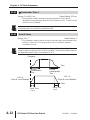
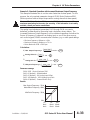
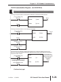
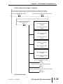
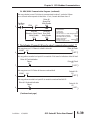
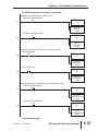
Programming the GS1 AC Drive
The GS1 AC Drive parameters are organized into 10 different groups according to their
functions. The illustration below shows you how to navigate through the parameter
groups and parameter settings. For a complete list of parameters, see CHAPTER 4.
Program
Mode
Press the PROG/ENTER key to enter program mode.
Only the parameter
groups will be displayed.
Use the UP/DOWN keys to cycle through the available parameter
groups. Press the PROG/ENTER key to select the desired parameter
group.
Select
Use the UP/DOWN keys to cycle through the parameters in the
Parameter
Group
selected parameter group.
When you reach your desired parameter, press the
0-
PROG/ENTER key to select the parameter.
Use the UP/DOWN keys to select the desired parameter setting.
Press the PROG/ENTER key to store the parameter setting into
!-
memory. “End” will display on the digital display to signal that
the parameter value has been changed.
After the parameter value has been set, the AC drive will cycle
2-
to the next parameter in the selected group. Repeat steps 3
through 6 to change another parameter setting.
3-
Select
Press the DISPL/RESET key if you need to
change from the parameter selection
menu to the parameter group menu.
Parameter
4-
0-00
5-
0-0!
Select
Parameter
Value
0-02
6-
8-
9-
3–4
50
0-03
60
0-04
400
GS1 Series AC Drive User Manual
end
2nd Edition
07/06/2011
Chapter 3: Keypad Operation and Quickstart
GS1 Quickstart
The following examples will help you quickly set up your GS1 AC Drive for two
common applications. The first example applies to an application that requires
constant torque, and the second example requires variable torque in its
application.
For a complete list and description of the parameters for the GS1 Series AC drives, refer
to CHAPTER 4, AC DRIVE PARAMETERS.
Example 1: Constant torque (e.g. conveyors, compressors, etc.)
In this example, the AC drive needs to operate a motor that is connected to a conveyor.
In order to decide which parameters need modifications, we will make a list of the needs
for the application.
Application Needs
• The AC drive must control a 230V, 1hp motor. The AC drive model that we
will use for this application is a GS1-21P0. An example of the motor
nameplate is shown below.
INVERTER DUTY MOTOR
HP
1
Volts
230
PHASE 3
TYPE
P
RPM
1725
AMPS
4.2
HZ
SF
1.15
60
DESIGN B
AMB
40°C
INSUL CLASS F
DUTY
ENCL
TEFC
CODE
CONT
K
• The maximum speed for the motor is 2000 rpm.
• The motor should accelerate to maximum speed in 5 seconds.
• The motor should decelerate from maximum speed in 5 seconds.
• The motor will require a high torque when starting.
• The operation of the motor (start, stop, etc.) will be controlled by external
control terminals. All keys on the GS1 keypad should be disabled.
• The frequency of the AC drive will be determined by a remote
potentiometer that provides a 0 to +10V signal.
• The display of the AC drive should show the motor speed (rpm) when
running.
2nd Edition
07/06/2011
GS1 Series AC Drive User Manual
3–5
Chapter 3: Keypad Operation and Quickstart
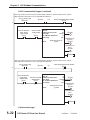
Parameter Setup (for example 1)
In order to meet the needs of this application, the parameters should be set as follows:
P0.00
Motor Nameplate Voltage
Setting: 230
Range: 200V series: 200/208/220/230/240
Default Setting: 240
This parameter setting is determined by the motor nameplate.
P0.01
Motor Nameplate Amps
Range: Drive Rated Amps x 0.3 to
Drive Rated Amps x 1.0
Setting: 4.2
Default Setting: Drive Rating (A)
This parameter setting is determined by the motor nameplate..
P0.02
Motor Base Frequency
Range: 50/60/400
Setting: 60
Default Setting 60
This parameter setting is determined by the motor nameplate.
P0.03
Motor Base RPM
Range: 375 to 9999 RPM
Setting: 1725
Default Setting: 1750
This parameter setting is determined by the motor nameplate.
P0.04
Motor Maximum RPM
Range: P0-03 to 9999 rpm
Setting: 2000
Default Setting: P0-03
This parameter setting is determined by the needs of the application.
WARNING: The Motor Maximum RPM parameter (P0.04) should never exceed the
maximum RPM rating for the motor you are using. If this information is not readily
available, consult your motor manufacturer.
P1.00
Stop Methods
Range: 0 - Ramp to Stop
1 - Coast to stop
Setting: 0
Default Setting: 0
The application requires that this parameter be set to Ramp to Stop
because the motor needs to stop under power. If the AC drive was set
for Coast to Stop, the AC drive would ignore the Deceleration Time
setting.
WARNING: If the Stop Method for the GS1 AC drive is set for Coast to Stop, the AC
drive will ignore any setting you have for Deceleration Time (P1.02).
3–6
GS1 Series AC Drive User Manual
2nd Edition
07/06/2011
Chapter 3: Keypad Operation and Quickstart
P1.01
Acceleration Time
Setting: 5.0
Range: 0.1 to 600 sec
Default Setting: 10 sec
The motor should accelerate from 0 rpm to Base RPM (P0.03) in
5 seconds.
P1.02
Deceleration Time
Setting: 5.0
Range: 0.1 to 600 sec
Default Setting: 30 sec
The motor should decelerate from Maximum RPM (P0.04) to 0 rpm in
5 seconds.
P2.00
Volts/Hertz Settings
Range: 0
1
2
3
–
–
–
–
General Purpose
High Starting Torque
Fans and Pumps
Custom
Setting: 1
Default Setting: 0
The GS1 Series AC drive has some predefined torque settings that meet
the needs of most applications. A custom setting is available if needed.
In this example, the application requires a high starting torque.
P3.00
Source of Operation Command
Setting: 2
Default Setting: 0
Settings
0
Operation Determined by Digital Keypad.
1
Operation determined by external control terminals.
Keypad STOP is enabled.
2
Operation determined by external control terminals.
Keypad STOP is disabled.
3
Operation determined by RS-485 interface.
Keypad STOP is enabled.
4
Operation determined by RS-485 interface.
Keypad STOP is disabled.
The AC drive operation will be determined by external control
terminals and the keypad stop will be disabled.
2nd Edition
07/06/2011
GS1 Series AC Drive User Manual
3–7
Chapter 3: Keypad Operation and Quickstart
P4.00
Source of Frequency Command
Setting: 2
Default: 0
Settings:
0
Frequency determined by keypad potentiometer.
1
Frequency determined by digital keypad up/down.
2
Frequency determined by 0 to +10V input on AI
terminal. AI switch must be set to “V”.
AI switch must be set to “V”
in order to use 0 to +10V input.
3
Frequency determined by 4 to 20mA input on AI
terminal. AI switch must be set to “I”.
4
Frequency determined by 0 to 20mA input on AI
terminal. AI switch must be set to “I”.
5
Frequency determined by RS-485 communication
interface.
The frequency of the AC drive will be determined by an external
potentiometer with a 0 to +10V signal.
P8.00
User Defined Display Function
Setting: 1
Default Setting: 0
Settings:
0
1
2
3
4
5
6
9
Output Frequency (Hz)
Motor Speed (rpm)
Output Frequency x P8.01
Output Current (A)
Motor Output Current (%)
Output Voltage (V)
DC Bus Voltage (V)
Frequency Setpoint
The AC drive display will show motor speed (rpm) when running.
3–8
GS1 Series AC Drive User Manual
2nd Edition
07/06/2011
Chapter 3: Keypad Operation and Quickstart
Example 2: Variable torque (e.g. fans, centrifugal pumps, etc.)
In this example, the AC drive needs to operate a motor that is connected to a centrifugal
pump. As in Example 1, we will make a list of the needs for the application in order to
decide which parameters need modifications.
Application Needs
• The AC drive must control a 208V, 1/2hp motor. The AC drive model we
will be use for this application is a GS1-20P5. An example of the motor
nameplate is shown below.
INVERTER DUTY MOTOR
HP
0.5
Volts
208
PHASE 3
TYPE
P
RPM
3525
AMPS
2.5
HZ
SF
1.15
60
DESIGN B
AMB
40°C
INSUL CLASS F
DUTY
ENCL
TEFC
CODE
CONT
K
• The maximum speed for the motor is 3600 rpm.
• The motor should accelerate to maximum speed in 20 seconds.
• The motor should coast to stop when operation is terminated.
• The motor will be turning a centrifugal pump.
• The operation of the motor (start, stop, etc.) will be controlled by the GS1
digital keypad.
• The frequency of the AC drive will be determined by the GS1 keypad
potentiometer.
• The display of the AC drive should show output current (A) when running.
Parameter Setup (for example 2)
In order to meet the needs of this application, the parameters should be set as follows:
P0.00
Motor Nameplate Voltage
Setting: 208
Range: 200V series: 200/208/220/230/240
Default Setting: 240
This parameter setting is determined by the motor nameplate.
P0.01
Motor Nameplate Amps
Range: Drive Rated Amps x 0.3 to
Drive Rated Amps x 1.0
Setting: 2.5
Default Setting: Drive Rating (A)
This parameter setting is determined by the motor nameplate.
2nd Edition
07/06/2011
GS1 Series AC Drive User Manual
3–9
Chapter 3: Keypad Operation and Quickstart
P0.02
Motor Base Frequency
Range: 50/60/400
Setting: 60
Default Setting: 60
This parameter setting is determined by the motor nameplate.
P0.03
Motor Base RPM
Range: 375 to 9999 RPM
Setting: 3525
Default Setting: 1750
This parameter setting is determined by the motor nameplate.
P0.04
Motor Maximum RPM
Setting: 3600
Range: P0.03 to 9999 RPM
Default Setting: P0.03
This parameter setting is determined by the needs of the application.
WARNING: The Motor Maximum RPM parameter (P0.04) should never exceed the
maximum rpm rating for the motor you are using. If this information is not readily
available, consult your motor manufacturer.
P1.00
Stop Methods
Range: 0 - Ramp to Stop
1 - Coast to stop
Setting: 1
Default Setting: 0
The application requires that this parameter be set to Coast to Stop.
WARNING: If the Stop Method for the GS1 AC drive is set for Coast to Stop, the AC
drive will ignore any setting you have for Deceleration Time (P1.02).
P1.01
Acceleration Time
Setting: 20.0
Range: 0.1 to 600 sec
Default Setting: 10 sec
The motor should accelerate from 0 rpm to Base RPM (P0.03) in 20
seconds.
P2.00
Volts/Hertz Settings
Range: 0
1
2
3
–
–
–
–
General Purpose
High Starting Torque
Fans and Pumps
Custom
Setting: 2
Default Setting: 0
The GS1 Series AC drive has some predefined torque settings that meet
the needs of most applications. A custom setting is available if needed.
In this example, the motor will be running a pump.
3–10
GS1 Series AC Drive User Manual
2nd Edition
07/06/2011
Chapter 3: Keypad Operation and Quickstart
P3.00
Source of Operation Command
Setting: 0
Default Setting: 0
Settings:
0
Operation Determined by Digital Keypad.
1
Operation determined by external control terminals.
Keypad STOP is enabled.
2
Operation determined by external control terminals.
Keypad STOP is disabled.
3
Operation determined by RS-485 interface.
Keypad STOP is enabled.
4
Operation determined by RS-485 interface.
Keypad STOP is disabled.
The AC drive operation will be determined by the digital keypad.
P4.00
Source of Frequency Command
Setting: 0
Default Setting: 0
Settings:
0
Frequency determined by keypad potentiometer.
1
Frequency determined by digital keypad up/down.
2
Frequency determined by 0 to +10V input on AI
terminal. AI switch must be set to “V”.
3
Frequency determined by 4 to 20mA input on AI
terminal. AI switch must be set to “I”.
4
Frequency determined by 0 to 20mA input on AI
terminal. AI switch must be set to “I”.
5
Frequency determined by RS-485 communication
interface.
The frequency of the AC drive will be determined by keypad
potentiometer.
P6.00
Electronic Thermal Overload Relay
Range: 0 – Constant Torque
1 – Variable Torque
2 – Inactive
Setting: 1
Default Setting: 0
• This function is used to limit the output power of the AC drive when
powering a “self-cooled” motor at low speed.
2nd Edition
07/06/2011
GS1 Series AC Drive User Manual
3–11
Chapter 3: Keypad Operation and Quickstart
P8.00
User Defined Display Function
Setting: 03
Default Setting: 00
Settings:
00
01
02
03
04
05
06
09
Output Frequency (Hz)
Motor Speed (rpm)
Output Frequency x P8.01
Output Current (A)
Motor Output Current (%)
Output Voltage (V)
DC Bus Voltage (V)
Frequency Setpoint
The AC drive display will show output current (A) when running.
For a complete list and description of the parameters for the GS1 Series AC drives, refer
to CHAPTER 4, AC DRIVE PARAMETERS.
3–12
GS1 Series AC Drive User Manual
2nd Edition
07/06/2011
AC DRIVE
PARAMETERS
CHAPTER
4
Contents of this Chapter...
GS1 Parameter Summary . . . . . . . . . . . . . . . . . . . . . . . . . . . . . . .4–2
Detailed Parameter Listings . . . . . . . . . . . . . . . . . . . . . . . . . . . . . .4–9
Motor Parameters . . . . . . . . . . . . . . . . . . . . . . . . . . . . . . . . . . . . . . . . .4–9
Ramp Parameters . . . . . . . . . . . . . . . . . . . . . . . . . . . . . . . . . . . . . . . . .4–11
Volts/Hertz Parameters . . . . . . . . . . . . . . . . . . . . . . . . . . . . . . . . . . . . .4–17
Digital Parameters . . . . . . . . . . . . . . . . . . . . . . . . . . . . . . . . . . . . . . . .4–20
Setting Explanations for Parameters P3.02 and P3.03 . . . . . . . . . . . . . . . . . . .4–22
Analog Parameters . . . . . . . . . . . . . . . . . . . . . . . . . . . . . . . . . . . . . . . .4–29
Analog Input Examples . . . . . . . . . . . . . . . . . . . . . . . . . . . . . . . . . . . . . . . . . .4–31
Presets Parameters . . . . . . . . . . . . . . . . . . . . . . . . . . . . . . . . . . . . . . . .4–38
Protection Parameters . . . . . . . . . . . . . . . . . . . . . . . . . . . . . . . . . . . . .4–39
Display Parameters . . . . . . . . . . . . . . . . . . . . . . . . . . . . . . . . . . . . . . . .4–47
Communication Parameters . . . . . . . . . . . . . . . . . . . . . . . . . . . . . . . . .4–48
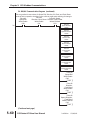
Chapter 4: AC Drive Parameters
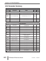
GS1 Parameter Summary
Parameter Summary
GS1
Parameter
Description
Range
Default User
Setting Setting
Motor Parameters
P0.00
Motor Nameplate Voltage
200/208/220/230/240
240
P0.01
Motor Nameplate Amps
Drive Rated Amps x 0.3 to 1.0
Drive
Rated
Amps
x 1.0
P0.02
P0.03
P0.04
Motor Base Frequency
50/60/400
60
Motor Base RPM
375 to 9999 RPM
1750
Motor Maximum RPM
P0.03 to 9999 RPM
P0.03
Ramp Parameters
P1.00
P1.01
P1.02
P1.03
P1.04
P1.05
P1.06
P1.07
P1.08
P1.09
Stop Methods
0: Ramp to Stop
1: Coast to Stop
0
Acceleration Time 1
0.1 to 600.0 sec
10.0
Deceleration Time 1
0.1 to 600.0 sec
30.0
Accel S-curve
0 to 7
0
Decel S-curve
0 to 7
0
Acceleration Time 2
0.1 to 600.0 sec
10.0
Deceleration Time 2
0.1 to 600.0 sec
30.0
Select method to use
2nd Accel/Decel
0: RMP2 from terminal
1: Transition Frequencies
P1.08 & P1.09
0
0.0 to 400.0 Hz
0.0
0.0 to 400.0 Hz
0.0
0.0 to 400.0 Hz
0.0
0.0 to 400.0 Hz
0.0
0.0 to 400.0 Hz
0.0
0.0 to 20.0 Hz
0.0
0 to 30%
0
0.0 to 5.0 sec
0.0
0.0 to 25.0 sec
0.0
0.0 to 60.0 Hz
0.0
Accel 1 to Accel 2
frequency transition
Decel 1 to Decel 2
frequency transition
Skip Frequency 1
P1.10
Skip Frequency 2
P1.11
Skip Frequency 3
P1.12
Skip Frequency Band
P1.17
DC Injection Voltage Level
P1.19
DC Injection during Start-up
P1.20
DC Injection during Stopping
P1.21
Start-point for DC Injection
P1.22
Parameter can be set during RUN Mode.
4–2
GS1 Series AC Drive User Manual
2nd Edition
07/06/2011
Chapter 4: AC Drive Parameters
Parameter Summary (continued)
GS1
Parameter
Description
Range
Default User
Setting Setting
Volts/Hertz Parameters
0:
1:
2:
3:
General Purpose
High Starting Torque
Fans and Pumps
Custom
P2.00
Volts/Hertz Settings
P2.01
P2.03
P2.04
P2.05
P2.06
P2.07
P2.08
Slip Compensation
0.0 to 10.0
0.0
Manual Torque Boost
0 to 10%
1
Mid-point Frequency
1.0 to 400 Hz
1.5
Mid-point Voltage
2.0 to 255V
10.0
Min. Output Frequency
1.0 to 20.0 Hz
1.5
Min. Output Voltage
2.0 to 50V
10.0
PWM Carrier Frequency
03 to 10 kHz
10
0
Digital Parameters
P3.00
P3.01
Source of Operation
Command
Multi-function Inputs 1 & 2
(DI1 - DI2)
P3.02
Multi-function Input 3 (DI3)
P3.03
Multi-function Input 4 (DI4)
0: Operation determined by digital keypad
1: Operation determined by external control
terminals, keypad STOP is enabled
2: Operation determined by external control
terminals, keypad STOP is disabled
3: Operation determined by RS-485
interface, keypad STOP is enabled
4: Operation determined by RS-485
interface, keypad STOP is disabled
0
0: DI1 - FWD / STOP, DI2 - REV / STOP
1: DI1 - RUN / STOP, DI2- REV / FWD
2: DI1 - RUN momentary (N.O.)
DI2 - REV / FWD
DI3 - STOP momentary (N.C.)
0
0: External Fault (N.O.)
1: External Fault (N.C.)
2: External Reset
3: Multi-Speed Bit 1
4: Multi-Speed Bit 2
9: Jog
10: External Base Block (N.O.)
11: External Base Block (N.C.)
12: Second Accel/Decel Time
13: Speed Hold
14: Increase Speed
15: Decrease Speed
16: Reset Speed to Zero
99: Input Disable
0
3
Parameter can be set during RUN Mode.
2nd Edition
07/06/2011
GS1 Series AC Drive User Manual
4–3
Chapter 4: AC Drive Parameters
Parameter Summary (continued)
GS1
Parameter
Description
Default User
Setting Setting
Range
Digital Parameters (continued)
P3.11
P3.16
P3.17
0: AC Drive Running
1: AC Drive Fault
2: At Speed
3: Zero Speed
4: Above Desired Frequency (P3.16)
5: Below Desired Frequency (P3.16)
6: At Maximum Speed (P0.04)
7: Over torque detected
8: Above Desired Current (P3.17)
9: Below Desired Current (P3.17)
Multi-Function Output
Terminal
0
Desired Frequency
0.0 to 400Hz
0.0
Desired Current
0.0 to Drive Rated Amps
0.0
Analog Parameters
P4.00
Source of Frequency
Command
P4.01
Analog Input Offset Polarity
P4.02
P4.03
0: Frequency determined by keypad
potentiometer
1: Frequency determined by digital keypad
up/down
2: Frequency determined by 0 to +10V
input on AI terminal (switch set to “V”)
3: Frequency determined by 4 to 20mA
input on AI terminal (switch set to “I”)
4: Frequency determined by 0 to 20mA
input on AI terminal (switch set to “I”)
5: Frequency determined by RS-485
communication interface
0: No Offset
1: Positive Offset
2: Negative Offset
0
0
Analog Input Offset
0.0 to 100.0%
0.0
Analog Input Gain
0.0 to 300.0%
100.0
P4.04
Analog Input Reverse
Motion Enable
P4.05
Loss of ACI Signal (4-20mA)
0: Forward Motion Only
1: Reverse Motion Enable
0: Decelerate to 0Hz
1: Stop immediately and display error
code “EF”
2: Continue operation by the last frequency
command
0
0
Presets Parameters
Jog
P5.00
Multi-Speed 1
P5.01
Multi-Speed 2
P5.02
Multi-Speed 3
P5.03
Parameter can be set during RUN Mode.
4–4
GS1 Series AC Drive User Manual
0.0 to 400Hz
6.0
0.0 to 400Hz
0.0
0.0 to 400Hz
0.0
0.0 to 400Hz
0.0
2nd Edition
07/06/2011
Chapter 4: AC Drive Parameters
Parameter Summary (continued)
GS1
Parameter
Description
Range
Default User
Setting Setting
Protection Parameters
P6.00
0: Constant Torque
(inverter/vector duty motors)
Electronic Thermal Overload
1: Variable Torque
Relay
(fan cooled standard motors)
2: Inactive
0
P6.01
Auto Restart after Fault
0
P6.02
Momentary Power Loss
P6.03
Reverse Operation Inhibit
P6.04
Auto Voltage Regulation
P6.05
Over-Voltage Trip Prevention
P6.06
Auto Adjustable Accel/Decel
P6.07
Over-Torque Detection Mode
P6.08
P6.09
Over-Torque Detection Level
P6.10
P6.11
P6.12
P6.13
P6.14
P6.15
P6.16
2nd Edition
Over-Torque Detection Time
Over-Current Stall Prevention
during Acceleration
Over-Current Stall Prevention
during Operation
Maximum Allowable
Power Loss Time
Base-Block Time
for Speed Search
Maximum Speed
Search Current Level
Upper Bound of
Output Frequency
Lower Bound of
Output Frequency
07/06/2011
0 to 10
0: Stop operation after momentary
power loss
1: Continue operation after momentary
power loss, speed search from Speed
Reference
2: Continue operation after momentary
power loss, speed search from
Minimum Speed
0: Enable Reverse Operation
1: Disable Reverse Operation
0: AVR enabled
1: AVR disabled
2: AVR disabled during decel
3: AVR disabled during stop
0: Enable Over-voltage Trip Prevention
1: Disable Over-voltage Trip Prevention
0: Linear Accel/Decel
1: Auto Accel, Linear Decel
2: Linear Accel, Auto Decel
3: Auto Accel/Decel
4: Auto Accel/Decel Stall Prevention
(limited by P1-01, P1-02, P1-05 and P1-06)
0: Disabled
1: Enabled during constant speed operation
2: Enabled during acceleration
30 to 200%
150
0.1 to 10.0
0.1
20 to 200%
130
20 to 200%
130
0.3 to 5.0 sec
2.0
0.3 to 5.0 sec
0.5
30 to 200%
150
0.1 to 400.0Hz
400.0
0.0 to 400.0Hz
0.0
0
0
0
0
0
0
GS1 Series AC Drive User Manual
4–5
Chapter 4: AC Drive Parameters
Parameter Summary (continued)
GS1
Parameter
Description
Default User
Setting Setting
Range
Protection Parameters (continued)
P6.30 *
P6.31
P6.32
P6.33
P6.34
P6.35
P6.36
00: Enable Line Start Lockout
01: Disable Line Start Lockout
Line Start Lockout
00
0: No Fault occurred
1: Over-current (oc)
2: Over-voltage (ov)
3: Overheat (oH)
Second Most Recent
4: Overload (oL)
Fault Record
5: Overload 1 (oL1)
6: Overload 2 (oL2)
Third Most Recent
7: External Fault (EF)
Fault Record
8: CPU failure 1 (CF1)
9: CPU failure 2 (CF2)
Fourth Most Recent
10: CPU failure 3 (CF3)
Fault Record
11: Hardware Protection Failure (HPF)
12: Over-current during accel (OCA)
Fifth Most Recent Fault Record 13: Over-current during decel (OCd)
14: Over-current during steady state (OCn)
18: External Base-Block (bb)
Sixth Most Recent Fault Record 19: Auto Adjust accel/decel failure (cFA)
20: Software protection code (codE)
Present Fault Record
00
00
00
00
00
00
* This parameter is available only with AC drive firmware v1.07 or higher.
Display Parameters
P8.00
0: Output Frequency (Hz)
1: Motor Speed (RPM)
2: Output Freq. X 8-01
3: Output Current (A)
User Defined Display Function
4: Motor Output Current (%)
5: Output Voltage (V)
6: DC Bus Voltage (V)
9: Frequency Setpoint
Frequency Scale Factor
P8.01
Parameter can be set during RUN Mode.
4–6
GS1 Series AC Drive User Manual
0.1 to 160.0
0
1.0
2nd Edition
07/06/2011
Chapter 4: AC Drive Parameters
Parameter Summary (continued)
GS1
Parameter
Description
Range
Default User
Setting Setting
Communications Parameters
P9.00
Communication Address
P9.01
Transmission Speed
P9.02
Communication Protocol
P9.03
0: 4800 baud
1: 9600 baud
2: 19200 baud
0: MODBUS ASCII mode, 7 data bits,
no parity, 2 stop bits
1: MODBUS ASCII mode, 7 data bits,
even parity, 1 stop bit
2: MODBUS ASCII mode, 7 data bits,
odd parity, 1 stop bit
3: MODBUS RTU mode, 8 data bits,
no parity, 2 stop bits
4: MODBUS RTU mode, 8 data bits,
even parity, 1 stop bit
5: MODBUS RTU mode, 8 data bits,
odd parity, 1 stop bit
0: Display fault and continue operating
1: Display fault and RAMP to stop
Transmission Fault Treatment
2: Display fault and COAST to stop
3: No fault displayed and continue operating
P9.04
Time Out Detection
P9.05
Time Out Duration
P9.07
1 to 254
Parameter Lock
0: Disable
1: Enable
07/06/2011
1
0
0
0
0.1 to 60.0 seconds
0: All parameters can be set and read
1: All parameters are read-only
99: Restores all parameters to factory defaults
P9.08
Restore to Default
Block Transfer Parameter 1
Parameters 0.00 to 8.01, 9.99
P9.11
Block Transfer Parameter 2
Parameters 0.00 to 8.01, 9.99
P9.12
Block Transfer Parameter 3
Parameters 0.00 to 8.01, 9.99
P9.13
Block Transfer Parameter 4
Parameters 0.00 to 8.01, 9.99
P9.14
Block Transfer Parameter 5
Parameters 0.00 to 8.01, 9.99
P9.15
Block Transfer Parameter 6
Parameters 0.00 to 8.01, 9.99
P9.16
Block Transfer Parameter 7
Parameters 0.00 to 8.01, 9.99
P9.17
Block Transfer Parameter 8
Parameters 0.00 to 8.01, 9.99
P9.18
Block Transfer Parameter 9
Parameters 0.00 to 8.01, 9.99
P9.19
Block Transfer Parameter 10
Parameters 0.00 to 8.01, 9.99
P9.20
Parameter can be set during RUN Mode.
2nd Edition
1
0.5
0
0
9.99
9.99
9.99
9.99
9.99
9.99
9.99
9.99
9.99
9.99
GS1 Series AC Drive User Manual
4–7
Chapter 4: AC Drive Parameters
Parameter Summary (continued)
GS1
Parameter
Description
Default User
Setting Setting
Range
Communications Parameters (continued)
P9.26
P9.27
Serial Comm Speed Reference
P9.28
Serial Comm Direction
Command
P9.29
P9.30
P9.31
P9.39 *
Serial Comm External Fault
P9.41
P9.42
0.0 to 400.0 Hz
Serial Comm RUN Command 0: Stop
Serial Comm Fault Reset
60.0
1: Run
0
0: Forward
1: Reverse
0
0: No fault
1: External fault
0
0: No action
1: Fault Reset
0
1: Jog
0
Serial Comm JOG Command 0: Stop
Firmware Version
#.##
#.##
GS Series Number
1:
2:
3:
4:
GS1
GS2
GS3
GS4
##
Manufacturer Model
Information
0:
1:
2:
3:
4:
5:
GS1-10P2 (120V, 1ph, 0.25HP)
GS1-10P5 (120V, 1ph, 0.5HP)
GS1-20P2 (230V, 1ph/3ph, 0.25HP)
GS1-20P5 (230V, 1ph/3ph, 0.5HP
GS1-21P0 (230V, 1ph/3ph, 1HP)
GS1-22P0 (230V, 3ph, 2HP)
##
* This parameter is available only with AC drive firmware v1.07 or higher.
Parameter can be set during RUN Mode.
4–8
GS1 Series AC Drive User Manual
2nd Edition
07/06/2011
Chapter 4: AC Drive Parameters
Detailed Parameter Listings
Parameter
Number
Parameter
Name
Motor Nameplate Voltage
P0.00
Range: 115V/230V series: 200/208/220/230/240
Default Setting: 240
• This parameter determines the Maximum Output Voltage of the AC drive. The Maximum Output
Voltage setting must be less than or equal to the rated voltage of the motor as indicated on the
motor nameplate. The setting value must be equal to or greater than the Mid-Point Voltage
(P2.05).
Parameter Setting
Range
Parameter
Description
Parameter Default
Setting
If the symbol is found next to the parameter name, the parameter can be edited
when the AC drive is in RUN Mode.
Motor Parameters
P0.00
Motor Nameplate Voltage
Range: 115/230V series: 200/208/220/230/240
Default Setting: 240
• This parameter determines the Maximum Output Voltage of the AC drive. The
Maximum Output Voltage setting must be less than or equal to the rated voltage of
the motor as indicated on the motor nameplate. The setting value must be equal
to or greater than the Mid-Point Voltage (P2.05).
P0.01
Motor Nameplate Amps
Range: Drive Rated Amps x 0.3 to
Drive Rated Amps x 1.0
Default Setting: Drive Rating (A)
• This parameter sets the output current to the motor. The value is determined by the
value found on the motor nameplate.
2nd Edition
07/06/2011
GS1 Series AC Drive User Manual
4–9
Chapter 4: AC Drive Parameters
P0.02
Motor Base Frequency
Range: 50/60/400
Default Setting: 60
• This value should be set according to the base frequency of the motor as indicated
on the motor nameplate. It sets the Maximum Voltage Frequency and determines
the volts per hertz ratio.
P0.03
Motor Base RPM
Range: 375 to 9999 RPM
Default Setting: 1750
• This value should be set according to rated Base RPM of the motor as indicated on
the motor nameplate.
P0.04
Motor Maximum RPM
Range: P0-03 to 9999 RPM
Default Setting: P0-03
• This value should be set according to the desired maximum speed of the motor.
WARNING: The Motor Maximum RPM parameter (P0.04) should never exceed the
maximum safe RPM rating for the motor you are using. If this information is not
readily available, consult your motor manufacturer.
• This value cannot be set lower than Motor Base RPM (P0.03).
This parameter, along with P 0.02 and P 0.03, determines the Maximum Output
Frequency of the AC Drive. The Maximum Output Frequency is can be calculated
as follows:
Max. Output Frequency =
Motor Max. RPM (P0.04)
x Base Frequency (P0.02)
( Motor
Base RPM (P0.03) )
If an output limit based on Maximum Output Frequency is desired, use the
following equation to determine the corresponding value for Motor Maximum
RPM:
Motor Maximum RPM =
4–10
( Motor Base Frequency (P0.02) ) x Motor Base RPM (P0.03)
Max. Output Frequency
GS1 Series AC Drive User Manual
2nd Edition
07/06/2011
Chapter 4: AC Drive Parameters
Ramp Parameters
Stop Methods
P1.00
Range: 0 Ramp to Stop
1 Coast to stop
Default Setting: 0
• This parameter determines how the motor is stopped when the AC drive receives a
valid stop command.
• Ramp: The AC drive decelerates the motor to Minimum Output Frequency (P2.06)
according to the deceleration time set in P1.02 or P1.06.
• Coast: The AC drive stops output instantly upon command, and the motor free
runs until it comes to a complete stop.
The drive application or system requirements will determine which stop method is needed.
Hz
Hz
Frequency
Frequency
Stops according to
deceleration time
Motor
Speed
Motor
Speed
Free running to stop
time
Operation
Command
?
decel
time
ON
OFF
Ramp
P1.01
time
ON
OFF
Coast
Acceleration Time 1
Range: 0.1 to 600.0 sec
Default Setting: 10 sec
• This parameter is used to determine the rate of acceleration for the AC drive to
reach Maximum Motor RPM (P0.04). The rate is linear unless S-Curve is
"Enabled."
2nd Edition
07/06/2011
GS1 Series AC Drive User Manual
4–11
Chapter 4: AC Drive Parameters
P1.02
Deceleration Time 1
Range: 0.1 to 600.0 sec
Default Setting: 30.0 sec
• This parameter is used to determine the time required for the AC drive to
decelerate from the Maximum Motor RPM (P0.04) down to 0Hz. The rate is linear
unless S-Curve is “Enabled.”
Bus over-voltage trips may be caused by motor regeneration during rapid deceleration.
If this tripping occurs, increase the deceleration time.
P1.03
Accel S-Curve
Range: 0 to 7
Default Setting: 0
• This parameter is used whenever the motor and load need to be accelerated more
smoothly. The Accel S-Curve may be set from 0 to 7 to select the desired
acceleration S Curve.
From the diagram shown below, the original setting accel/decel time will be for
reference when the function of the S-curve is enabled. The actual accel/decel time will
be determined based on the S-curve selected (1 to 7).
Frequency
Time
S-curve
characteristics
Time
S-curve
characteristics
Time
1-04 = 0
"Decel S curve Disabled"
1-03 = 0
"Accel S curve Disabled"
Time
Accel Time
1 or 2
4–12
GS1 Series AC Drive User Manual
Decel Time
1 or 2
2nd Edition
07/06/2011
Chapter 4: AC Drive Parameters
P1.04
Decel S-Curve
Range: 0 to 07
Default Setting: 0
• This parameter is used whenever the motor and load need to be decelerated more
smoothly. The Decel S-Curve may be set from 0 to 7 to select the desired
deceleration S-Curve.
From the diagram shown below, the original setting accel/decel time will be for
reference when the function of the S-curve is enabled. The actual accel/decel time will
be determined based on the S-curve selected (1 to 7).
Frequency
1-04
1-03
(1)
(2)
(4)
(3)
Time
(1)
(2)
(3)
(4)
S curve is disabled in (1), (2)
1-03 sets S curve for (3)
1-04 sets S curve for (4)
P1.05
Acceleration Time 2
Range: 0.1 to 600.0 sec
Default Setting: 10.0
• The Second Acceleration Time determines the time for the AC drive to accelerate
from 0 RPM to Maximum Motor RPM (P0.04). Acceleration Time 2 (P1.05) can be
selected using a multi-function input terminal or frequency transition (P1.07).
P1.06
Deceleration Time 2
Range: 0.1 to 600.0 sec
Default Setting: 30 sec
• The Second Deceleration Time determines the time for the AC drive to decelerate
from Maximum Motor RPM (P0.04) to 0 RPM. Deceleration Time 2 (P1.06) can be
selected using a multi-function input terminal or frequency transition (P1.07).
2nd Edition
07/06/2011
GS1 Series AC Drive User Manual
4–13
Chapter 4: AC Drive Parameters
P1.07
Select method for 2nd Accel/Decel
Range: 0: Second Accel/Decel from terminal
1: Frequency Transition
P1.08 & P1.09
Default Setting: 0
• The second set of acceleration and deceleration times P1.05 and P1.06 can be
selected either with a multi-function input terminal programmed to Second
Accel/Decel or by the values of the transition frequencies P1.08 and P1.09
Second Accel/Decel Times selected with Multi-Function Input Terminal
Frequency
Maximum Output
Frequency (0-04)
Accel 1
1-01
Accel 2
1-05
Decel 2
1-06
Decel 1
1-02
Time
Multi-function
Input Terminal
P1.08
On
Off
Accel 1 to Accel 2 Frequency Transition
Range: 0.0 to 400.0 Hz
Default Setting: 0.0
Second Accel/Decel Times selected with Frequency Transition
Frequency
Maximum Output
Frequency (0-04)
Accel 1 to Accel 2
Frequency Transition
(1-08)
Accel 2
1-05
Accel 1
1-01
P1.09
Decel 2
1-06
Decel 1
1-02
Decel 2 to Decel 1
Frequency Transition
(1-09)
Time
Decel 1 to Decel 2 Frequency Transition
Range: 0.0 to 400.0 Hz
Default Setting: 0.0
Refer to the P1.08 diagram.
4–14
GS1 Series AC Drive User Manual
2nd Edition
07/06/2011
Chapter 4: AC Drive Parameters
P1.10
Skip Frequency 1
Range: 0.0 to 400.0Hz
P1.11
Skip Frequency 2
Range: 0.0 to 400.0Hz
P1.12
Default Setting: 0.0
Default Setting: 0.0
Skip Frequency 3
Range: 0.0 to 400.0 Hz
Default Setting: 0.0
• P1.10, P1.11, and P1.12 determine the location of the frequency bands that will
be skipped during AC drive operation.
P1.17
Skip Frequency Band
Range: 0.0 to 20.0 Hz
Default Setting: 0.0
• This parameter determines the frequency band for a given Skip Frequency (P1.10,
P1.11, or P1.12). Half of the Skip Frequency Band is above the Skip Frequency
and the other half is below. Programming this parameter to 0.0 disables all skip
frequencies.
Output frequency
Skip Frequency 3
P1.12
Skip Frequency 2
P1.11
Skip Frequency 1
P1.10
Skip Frequency
Set Point
2nd Edition
07/06/2011
Skip Frequency Band
P1.17
GS1 Series AC Drive User Manual
4–15
Chapter 4: AC Drive Parameters
P1.19
DC Injection Voltage Level
Range: 0 to 30%
Default Setting: 0
• This parameter determines the amount of DC Braking Voltage applied to the motor
during start-up and stopping. When setting DC Braking Voltage, please note that
the setting is a percentage of the rated voltage of the drive. It is recommended to
start with a low DC Braking Voltage Level and then increase until proper holding
torque has been attained.
P1.20
DC Injection during Start-up
Range: 0.0 to 5.0 sec
Default Setting: 0.0
• This parameter determines the duration of time that the DC Braking Voltage will be
applied to the motor during the AC drive start-up. DC Braking will be applied for
the time set in this parameter until the Minimum Frequency is reached during
acceleration.
P1.21
DC Injection during Stopping
Range: 0.0 to 25.0 sec
Default Setting: 0.0
• This parameter determines the duration of time that the DC braking voltage will be
applied to the motor during stopping. If stopping with DC Braking is desired, then
P1.00 must be set to Ramp to Stop (00).
P1.22
Start-point for DC Injection
Range: 0.0 to 60.0 Hz
Default Setting: 0.0
• This parameter determines the frequency when DC Braking will begin during
deceleration.
Master
Frequency
Min. Output
Frequency
Operation
Command
Start-Point for DC Braking
P1.22
time
P1.21
P1.20
ON
OFF
DC Injection Voltage Level
P1.19
4–16
GS1 Series AC Drive User Manual
2nd Edition
07/06/2011
Chapter 4: AC Drive Parameters
Volts/Hertz Parameters
P2.00
Volts/Hertz Settings
Range: 0
1
2
3
-
General Purpose (constant torque)
High Starting Torque
Fans and Pumps (variable torque)
Custom
Default Setting: 0
P2.04 through P2.07 are only used when the Volts/Hertz parameter (P2.00) is set to 3.
P2.00 = 0: General Purpose (constant torque)
P2.00 = 3: Custom
Voltage
Volts
Volts
P0.00
P0.00
P0.00
P2.05
10
Hz
1.5
1.5
60/400
60/400Hz Base Frequency
P2.07
10
50
Hz
50Hz Base Frequency
P2.06 P2.04
Frequency
P2.02 P0.04
x P0.02
P0.03
P2.00 = 1: High Starting Torque
Volts
Volts
P0.00
P0.00
23
18
14
23
Hz
60/400
1.5 3
60/400Hz Base Frequency
1.3 2.2
50
Hz
50Hz Base Frequency
P2.00 = 2: Fans and Pumps (variable torque)
Volts
Volts
P0.00
P0.00
50
10
50
10
1.5
30
Hz
60/400
60/400Hz Base Frequency
2nd Edition
07/06/2011
1.3
25
50
Hz
50Hz Base Frequency
GS1 Series AC Drive User Manual
4–17
Chapter 4: AC Drive Parameters
P2.01
Slip Compensation
Range: 0.0 to 10.0
Default Setting: 0.0
• When controlling an asynchronous induction motor, an increase in load on the
motor will result in an increase in slip within the motor. This parameter may be
used to compensate the nominal slip within a range of 0 to 10. When the output
current of the AC drive is greater than 40% of the Motor Nameplate Amps (P0.01),
the AC drive will adjust its output frequency according to this parameter.
P2.03
Manual Torque Boost
Range: 0 to 10%
Default Setting: 1
• This parameter provides a gain that increases the output voltage command to
enhance output torque.
P2.04 through P2.07 are used only when the Volts/Hertz parameter (P2.00) is set to 3.
P2.04
Mid-point Frequency
Range: 1.0 to 400 Hz
Default Setting: 1.5
• This parameter sets the Mid-Point Frequency of V/F curve. With this setting, the
V/F ratio between Minimum Frequency and Mid-Point frequency can be
determined.
• This parameter must be greater than or equal to the Minimum Output Frequency
(P2.06) and less than or equal to the Maximum Voltage Frequency (P0.02).
P2.05
Mid-point Voltage
Range: 2.0 to 255.0V
Default Setting: 10.0
• This parameter sets the Mid-Point Voltage of any V/F curve. With this setting, the
V/F ratio between Minimum Frequency and Mid-Point Frequency can be
determined.
• This parameter must be equal to or greater than the Minimum Output Voltage
(P2.07) and equal to or less than the Maximum Output Voltage (P0.00).
4–18
GS1 Series AC Drive User Manual
2nd Edition
07/06/2011
Chapter 4: AC Drive Parameters
P2.06
Minimum Output Frequency
Range: 1.0 to 20.0 Hz
Default Setting: 1.5
• This parameter sets the Minimum Output Frequency of the AC drive.
• This parameter must be less than or equal to the Mid-Point Frequency (P2.04).
P2.07
Minimum Output Voltage
Range: 2.0 to 50.0V
Default Setting: 10.0
• This parameter sets the Minimum Output Voltage of the AC drive.
• This parameter must be equal to or less than Mid-Point Voltage (P2.05).
P2.08
PWM Carrier Frequency
Range: 3 to 10 kHz
Default Setting: 10
• This parameter sets the carrier frequency of PWM (Pulse-Width Modulated) output.
• In the table below, we see that the carrier frequency of PWM output has a
significant influence on the electromagnetic noise, leakage current, heat
dissipation of the AC drive and the acoustic noise to the motor.
2nd Edition
Carrier
Frequency
Acoustic Noise
3kHz
significant
minimal
minimal
10kHz
minimal
moderate
moderate
07/06/2011
Electromagnetic Noise,
Heat Dissipation
Leakage Current
GS1 Series AC Drive User Manual
4–19
Chapter 4: AC Drive Parameters
Digital Parameters
P3.00
Source of Operation Command
Default Setting: 0
Settings
0
Operation Determined by Digital Keypad
1
Operation determined by external control terminals.
Keypad STOP is enabled.
2
Operation determined by external control terminals.
Keypad STOP is disabled.
3
Operation determined by RS-485 interface.
Keypad STOP is enabled.
4
Operation determined by RS-485 interface.
Keypad STOP is disabled.
• This parameter sets the input source for the AC drive operation commands.
• Refer to P3.01 and P3.03 for more details.
P3.01
Multi-function Inputs 1 & 2(DI1-DI2)
Default Setting: 0
Settings
0
DI1 - FWD/STOP
DI2 - REV/STOP
1
DI1 - RUN/STOP
DI2 - REV/FWD
2
DI1 - RUN (N.O. latching input)
DI2 - REV/FWD
DI3 - STOP (N.C. latching input)
Multi-function Input Terminals DI1 and DI2 do not have separate parameter
designations. DI1 and DI2 must be used in conjunction with one another to operate
two and three wire control.
P3.01: Setting 0
FWD/STOP
REV/STOP
4–20
DI1
DI1
DI2
Result
OFF
OFF
STOP
ON
OFF
FWD
DI2
OFF
ON
REV
CM
ON
ON
STOP
GS1 Series AC Drive User Manual
2nd Edition
07/06/2011
Chapter 4: AC Drive Parameters
P3.01: Setting 1
P3.01: Setting 2
DI1- RUN command
Latching input (N.O.)
Runs when closed
STOP
RUN/STOP
FWD/REV
DI1
DI2
CM
P3.02
DI1- RUN/STOP select
"Open" : Stop
"Close" : Run
DI2- FWD/REV select
"Open" : FWD
"Close" : REV
RUN
DI1
DI3
FWD/REV
DI2
CM
DI2- FWD/REV select
"Open" : FWD
"Close" : REV
DI3- STOP command
Latching input (N.C.)
Stops when open
The external STOP and RUN pushbuttons are momentary.
The circuit latches as does a typical 3-wire control circuit.
Multi-Function Input 3 (DI3)
Default Setting: 0
Settings same as for P3.03, except when P3.01 = 2.
P3.02 automatically sets to 99 when P3.01=2.
P3.03
Multi-Function Input 4 (DI4)
Settings for P3.02 and P3.03
Settings
2nd Edition
07/06/2011
0
1
2
3
4
9
10
11
12
13
14
15
16
99
Default Setting: 3
External Fault (N.O.)
External Fault (N.C.)
External Reset
Multi-Speed Bit 1
Multi-Speed Bit 2
Jog
External Base Block (N.O.)
External Base Block (N.C.)
Second Accel/Decel Time
Speed Hold
Increase Speed (P4.00 must be set to 1)
Decrease Speed (P4.00 must be set to 1)
Reset Speed to Zero (P4.00 must be set to 1)
Input Disable
GS1 Series AC Drive User Manual
4–21
Chapter 4: AC Drive Parameters
Setting Explanations for Parameters P3.02 and P3.03
Setting 0: External Fault (N.O.)
When an External Fault input signal is received, the AC drive output will turn off,
the drive will display “EF” on the LED Display, and the motor will Coast to Stop.
To resume normal operation, the external fault must be cleared, and the drive must
be reset.
External Fault (N.O)
DI3-DI4
DI3-DI4: External Fault (N.O.)
"Close": Drive receives external fault input signal
CM
Setting 1: External Fault (N.C.)
External Fault (N.C)
DI3-DI4
DI3-DI4: External Fault (N.C.)
"Open": Drive receives external fault input signal
CM
Setting 2: External Reset
An External Reset has the same function as the Reset key on the digital keypad.
Use an External Reset to reset the drive after a fault.
External Reset (N.O.)
DI3-DI4
DI3-DI4: External Reset
"Close": Drive receives external reset input signal
CM
4–22
GS1 Series AC Drive User Manual
2nd Edition
07/06/2011
Chapter 4: AC Drive Parameters
Settings 3 and 4: Multi-Speed Bits 1 and 2
The three Multi-Speed Bits are used to select the multi-speed settings defined by
parameters P5.01 to P5.03.
Multi-Speed Bits
03: Mult-speed Bit 1
DI3-DI4
04: Mult-speed Bit 2
DI3-DI4
CM
Speed Selection
Bit 2
Bit 1
OFF
OFF
4-00: Source of Frequency
OFF
ON
5-01: Multi-Speed 1
ON
OFF
5-02: Multi-Speed 2
ON
ON
5-03: Multi-Speed 3
(DI3 or DI4 can be assigned as Multi-Speed Bit 1 or as Multi-Speed Bit 2.)
In order to use the Multi-Speed settings, parameters P5.01 to P5.03 must be set.
When all multi-speed inputs are off, the AC drive reverts back to the Command
Frequency (P4.00).
Setting 9: Jog Command
This setting configures a Multi-function Input Terminal to give the Jog Command
when activated. P5.00 sets the Jog Speed.
Jog Command
DI3-DI4
DI3-DI4: Jog Command
"Close": Drive receives Jog Command signal
CM
The Jog Command cannot be used when the motor is running.
The motor must be stopped to initiate this command.
2nd Edition
07/06/2011
GS1 Series AC Drive User Manual
4–23
Chapter 4: AC Drive Parameters
Setting 10 and 11: External Base Block (N.O.) and External Base Block (N.C.)
Value 10 is for a normally open (N.O) input and value 11 is for a normally closed
(N.C.) input.
DI3-DI4: Base Block Input
Base Block (N.O.)
DI3-DI4
Base Block (N.C)
CM
DI3-DI4
CM
When an External Base Block is activated, the LED display shows bb, the AC
drive stops all output, and the motor will free run. When the External Base Block
is deactivated, the AC drive will start the speed search function and synchronize
with the motor speed. The AC drive will then accelerate to the Master Frequency
6-13
Refer also to P6.13 (Base-Block Time for Speed Search) and P6.14 (Maximum
Speed Search Current Level).
4–24
GS1 Series AC Drive User Manual
2nd Edition
07/06/2011
Chapter 4: AC Drive Parameters
Setting 12: Second Accel/Decel Time
Multi-function Input Terminals DI3 and DI4 can be set to select between
Accel/Decel times 1 and 2. Parameters 1.01 and 1.02 set Accel 1 and Decel 1
times. Parameters 1.05 and 1.06 set Accel 2 and Decel 2 times.
Accel/Decel 2
DI3-DI4
DI3-DI4: Accel/Decel Time 2 Command
"Close": Drive receives Accel/Decel 2 Command signal
CM
Frequency
Maximum Output
Frequency (0-04)
Accel 2
1-05
Accel 1
1-01
Decel 2
1-06
Decel 1
1-02
Time
Multi-function
Input Terminal
On
Off
Setting 13: Speed Hold
When the Speed Hold command is received, the drive acceleration or
deceleration is stopped and the drive maintains a constant speed.
Freqency
Master Freqency
Accel inhibit
Decel inhibit
Actual Operation Freq.
Accel inhibit
Decel inhibit
Actual Operation Freqency
Time
Speed Hold
Run
Command
2nd Edition
07/06/2011
ON
ON
ON
ON
ON
OFF
GS1 Series AC Drive User Manual
4–25
Chapter 4: AC Drive Parameters
Settings 14 and 15: Increase and Decrease Speed
(Electronic Motor Operated Potentiometer)
Settings 14 and 15 allow the Multi-function terminals to be used to increase or
decrease speed incrementally. Each time an increase/decrease speed input is
received the Master Frequency will increase/decrease by one unit.
Setting 14: Increase
Setting 15: Decrease
DI3-DI4
DI3-DI4: Increase or Decrease Frequency
"Close": Drive receives Increase or Decrease Frequency Input
DI3-DI4
CM
In order to use these settings, P4.00 must be set to 1.
Setting 16: Reset Speed to Zero
Reset Speed to Zero
DI3-DI4
DI3-DI4: Reset Speed to Zero
"Close": Drive receives Reset Speed to Zero signal
CM
Setting 99: Multi-Function Input Disable
Setting a Multi-Function Input to 99 will disable that input. The purpose of this
function is to provide isolation for unused Multi-Function Input Terminals. Any
unused terminals should be programmed to 99 to make sure they have no effect
on drive operation.
Any unused terminals should be programmed to 99
to make sure they have no effect on drive operation.
4–26
GS1 Series AC Drive User Manual
2nd Edition
07/06/2011
Chapter 4: AC Drive Parameters
P3.11
Multi-function Output Terminal
Default Setting: 0
Settings:
0
1
2
3
4
5
6
7
8
9
AC Drive Running
AC Drive Fault
At Speed
Zero Speed
Above Desired Frequency (P3.16)
Below Desired Frequency (P3.16)
At Maximum Speed (P0.04)
Over Torque Detected
Above Desired Current (P3.17)
Below Desired Current (P3.17)
Function Explanations:
Setting 0: AC Drive Running – The terminal will be activated when there is an
output from the drive.
Setting 1: AC Drive Fault – The terminal will be activated when one of the faults
listed under parameters P6.31 through P6.36 occurs.
Setting 2: At Speed – The terminal will be activated when the AC drive attains the
Command Frequency (P4.00).
Setting 3: Zero Speed – The output will be activated when Command Frequency
(P4.00) is lower than the Minimum Output Frequency (P2.06).
Setting 4: Above Desired Frequency – The output will be activated when the AC
drive is above the Desired Frequency (P3.16).
Setting 5: Below Desired Frequency – The output will be activated when the AC
drive is below the Desired Frequency (P3.16).
Setting 6: At Maximum Speed – The output will be activated when the AC drive
reaches Motor Maximum RPM (P0.04).
Setting 7: Over Torque Detected – The output will be activated when the AC drive
reaches the Over-torque Detection Level (P6.08) and exceeds this level
for a time greater than the Over-torque Detection Time (P6.09).
Setting 8: Above Desired Current – The output will be activated when the AC drive
is above the Desired Current (P3.17).
Setting 9: Below Desired Current – The output will be activated when the AC drive
is below the Desired Current (P3.17).
2nd Edition
07/06/2011
GS1 Series AC Drive User Manual
4–27
Chapter 4: AC Drive Parameters
P3.16
Desired Frequency
Range: 0.0 to 400.0Hz
Default Setting: 0.0
• If the Multi-function output terminal is set to function as Desired Frequency
Attained (P3.11 = 04 or 05), then the output will be activated when the
programmed frequency is attained.
Frequency
Maximum Output
Frequency
Desired Frequency
P3.16
Time
Desired Frequency
Attained Indication
P3.11
Max. Output Frequency =
P3.17
ON
OFF
Motor Max. RPM (P0.04)
x Base Frequency (P0.02)
( Motor
Base RPM (P0.03) )
Desired Current
Range: 0.0 to <Drive Rated Amps>
Default Setting: 0.0
• If the Multi-function output terminal is set to function as Desired Current Attained
(P3.11 = 08 or 09), then the output will be activated when the programmed
current is attained.
Current
Maximum Output
Current
Desired Current
P3.17
Time
Desired Current
Attained Indication
P3.11
4–28
GS1 Series AC Drive User Manual
ON
OFF
2nd Edition
07/06/2011
Chapter 4: AC Drive Parameters
Analog Parameters
P4.00
Source of Frequency Command
Default: 0
Settings:
0
Frequency determined by keypad potentiometer.
1
Frequency determined by digital keypad up/down.
2
Frequency determined by 0 to +10V input on AI terminal.
Analog input switch must be set to “V”.
AI switch must be set to “V”
in order to use a 0 to +10V input.
3
Frequency determined by 4 to 20mA input on AI terminal.
Analog input switch must be set to “I”.
AI switch must be set to “I”
in order to use a 4 to 20mA input.
4
Frequency determined by 0 to 20mA input on AI terminal.
Analog input switch must be set to “I”.
AI switch must be set to “I”
in order to use a 0 to 20mA input.
5
Frequency determined by RS-485 communication interface.
P4.01 to P4.04 are used when the source of frequency command is the analog signal
(0 to +10VDC, 4 to 20mA, or 0 to 20mA).
Refer to the Analog Input Examples later in this section.
P4.01
Analog Input Offset Polarity
Range: 0 Offset disabled
1 Positive Offset
2 Negative Offset
Default Setting: 0
• This parameter sets the potentiometer Bias Frequency to be positive or negative.
• The Analog Input Offset calculation will also define the Offset Polarity. See the
note after P4.02.
• P4.01 to P4.04 are used when the source of frequency command is the analog
signal (0 to +10VDC, 4 to 20mA, or 0 to 20mA).
2nd Edition
07/06/2011
GS1 Series AC Drive User Manual
4–29
Chapter 4: AC Drive Parameters
P 4.02
Analog Input Offset
Range: 0.0 to 100%
This parameter can be set during the operation.
Default Setting: 0.0
• This parameter provides a frequency offset for an analog input.
• Use the equation below to determine the Analog Input Offset. For this equation,
you will need to know the necessary Minimum and Maximum Frequency
References needed for your application.
Analog Offset % =
(
Min. Frequency Reference
Max. Frequency Reference
) x 100
The result of the Analog Input Offset calculation will also define the Analog Input Offset
Polarity (P4.01). A positive answer means you should have a positive offset. A
negative answer means you should have a negative offset.
• P4.01 to P4.04 are used when the source of frequency command is the analog
signal (0 to +10VDC, 4 to 20mA, or 0 to 20mA).
P4.03
Analog Input Gain
Range: 0.0 to 300.0%
This parameter can be set during the operation.
Default Setting: 100.0
• This parameter sets the ratio of analog input vs frequency output.
• Use the equation below to calculate the Analog Input Gain. For this equation, you
will need to know the minimum and maximum set-point frequencies needed for
your application.
Analog Gain % =
Reference – Min. Frequency Reference
( Max. FrequencyMaximum
) x 100
Output Frequency
• P4.01 to P4.04 are used when the source of frequency command is the analog
signal (0 to +10VDC, 4 to 20mA, or 0 to 20mA).
P4.04
Analog Input Reverse Motion Enable
Range: 0 Forward Motion Only
1 Reverse Motion Enable
Default Setting: 0
• P4.01 to P4.04 are used when the source of frequency command is the analog
signal (0 to +10VDC, 4 to 20mA, or 0 to 20mA).
P4.05
Loss of ACI Signal (4–20mA)
Range: 0 - Decelerate to 0Hz
Default Setting: 0
1 – Stop immediately and display “EF”.
2 – Continue operation by the last frequency command
• This parameter determines the operation of the drive when the ACI frequency
command is lost.
4–30
GS1 Series AC Drive User Manual
2nd Edition
07/06/2011
Chapter 4: AC Drive Parameters
Analog Input Examples
Use the equations below when calculating the values for the Maximum Output
Frequency, Analog Input Offset, Analog Input Gain, and the Mid-point Frequency.
A) Max. Output Frequency =
Motor Max. RPM (P0.04)
x Base Frequency (P0.02)
( Motor
Base RPM (P0.03) )
The Maximum Output Frequency is not a parameter setting, but is needed in order to
calculate the Analog Gain. The default Maximum Output Frequency for the GS1 drive is
60 Hz. If parameters P0.02, P0.03, or P0.04 are changed, then the Maximum Output
Frequency will change.
B) Analog Offset % =
(
Min. Frequency Reference
Max. Frequency Reference
) x 100
C) Analog Gain % =
Reference – Min. Frequency Reference
( Max. FrequencyMaximum
) x 100
Output Frequency
D) Mid-point Freq. =
( Max. Freq. Reference 2– Min. Freq. Reference ) + Min. Freq. Reference
The Mid-point Frequency calculation shows the frequency reference of the drive when
the potentiometer or other analog device is at its mid-point.
2nd Edition
07/06/2011
GS1 Series AC Drive User Manual
4–31
Chapter 4: AC Drive Parameters
Example 1: Standard Operation
This example illustrates the default operation of the drive. The example is given to
further illustrate the use of the analog calculations. The full range of the analog
input signal corresponds to the full forward frequency range of the AC drive.
• Minimum Frequency Reference = 0Hz
• Maximum Frequency Reference = 60 Hz
Calculations
A) Max. Output Frequency =
B) Analog Offset % =
C) Analog Gain % =
( 1750 rpm ) x 60Hz = 60Hz
1750 rpm
( 60Hz ) x 100 = 0%
0Hz
– 0Hz
( 60Hz60Hz
) x 100 = 100%
D) Mid-point Frequency =
( 60Hz2– 0Hz ) + 0Hz = 30Hz
Parameter Settings
P4.01: 00 (default) – Offset disabled
P4.02: 00 (default) – 0% Analog Input Offset
P4.03: 100 (default) – 100% Analog Input Gain
P4.04: 00 (default) – Forward Motion Only
Results
Maximum
Output
60Hz
Frequency
30Hz
0Hz
0V
0mA
4mA
4–32
5V
10mA
12mA
GS1 Series AC Drive User Manual
10V
20mA
20mA
2nd Edition
07/06/2011
Chapter 4: AC Drive Parameters
Example 2: Standard Operation with Increased Maximum Output Frequency
This example illustrates how to run the motor faster than its base speed. For this
purpose, the only required parameter change is P0.04, Motor Maximum RPM.
(Motors produce reduced output torque when running above their base speed.)
WARNING: The Motor Maximum RPM parameter (P0.04) should never exceed the
maximum speed rating for the motor you are using. If this information is not readily
available, consult your motor manufacturer.
The analog input adjustment parameters P4.01 through P4.04 can remain
defaulted, as determined by the analog input calculations shown below. The
increased Maximum Output Frequency can be obtained regardless of whether the
Source of Frequency Command is an analog input or one of the other sources,
such as the keypad, RS-485 communication interface, jog, or multi-speed settings.
• Minimum Frequency Reference = 0Hz
• Maximum Frequency Reference = 70 Hz
• Motor Maximum RPM = 2042 rpm
Calculations
A) Max. Output Frequency =
B) Analog Offset % =
C) Analog Gain % =
(
RPM
x 60Hz = 70Hz
( 2042
1750 RPM )
0Hz
( 70Hz
) x 100 = 0%
70Hz – 0Hz
70Hz
D) Mid-point Frequency =
(
) x 100 = 100%
70Hz – 0Hz
2
) + 0Hz = 35Hz
Parameter Settings
P0.04: 2042 – Motor Maximum RPM
P4.01: 00 (default) – Offset disabled
P4.02: 00 (default) – 0% Analog Input Offset
P4.03: 100 (default) – 100% Analog Input Gain
P4.04: 00 (default) – Forward Motion Only
Results
Max. Output Frequency 70Hz
Motor Base Frequency 60Hz
Mid-Point Frequency 35Hz
0Hz
0V
0mA
4mA
2nd Edition
07/06/2011
5V
10mA
12mA
10V
20mA
20mA
GS1 Series AC Drive User Manual
4–33
Chapter 4: AC Drive Parameters
Example 3: Positive Offset
In this example, the Analog Input will have a positive offset while still using the
full scale of the potentiometer or other analog signal device. When the analog
signal is at its lowest value (0V, 0mA, or 4mA), the set-point frequency will be at
10Hz. When analog signal is at its maximum value (10V or 20mA), the set-point
frequency will be 60 Hz.
• Minimum Frequency Reference = 10 Hz
• Maximum Frequency Reference = 60 Hz
Calculations
A) Max. Output Frequency =
B) Analog Offset % =
C) Analog Gain % =
( 1750 rpm ) x 60Hz = 60Hz
1750 rpm
( 60Hz ) x 100 = 16.7%
10Hz
– 10Hz
( 60Hz60Hz
) x 100 = 83.3%
D) Mid-point Frequency =
( 60Hz 2– 10Hz ) + 10Hz = 35Hz
Parameter Settings
P4.01: 01 – Positive Input Offset Polarity
P4.02: 16.7 – 16.7% Analog Input Offset
P4.03: 83.3 – 83.3% Analog Input Gain
P4.04: 00 (default) – Forward Motion Only
Results
Maximum Output 60Hz
Frequency
35Hz
10Hz
Positive Offset
0Hz
4–34
0V
0mA
4mA
5V
10mA
12mA
GS1 Series AC Drive User Manual
10V
20mA
20mA
2nd Edition
07/06/2011
Chapter 4: AC Drive Parameters
Example 4: Forward and Reverse Operation
In this example, the potentiometer (or other analog signal device) is programmed
to run a motor full-speed in both forward and reverse directions. The frequency
reference will be 0Hz when the potentiometer is positioned at mid-point of its
scale. Parameter P4.04 must be set to enable reverse motion.
When calculating the values for the Analog Input using reverse motion, the reverse
frequency reference should be shown using a negative (-) number. Pay special
attention to signs (+/-) for values representing reverse motion.
• Minimum Frequency Reference = -60 Hz (reverse)
• Maximum Frequency Reference = 60 Hz
Calculations
A) Max. Output Frequency =
B) Analog Offset % =
( 1750 rpm ) x 60Hz = 60Hz
1750 rpm
( 60Hz ) x 100 = -100%
-60Hz
The negative (-) value for the Analog Offset % shows that a negative offset is needed
for P4.01.
C) Analog Gain % =
– (-60Hz)
(60Hz60Hz
) x 100 = 200%
D) Mid-point Frequency =
( 60Hz –2(-60Hz) ) + (-60Hz) = 0Hz
Parameter Settings
P4.01: 02 – Negative Input Offset Polarity
P4.02: 100 – 100% Analog Input Offset
P4.03: 200 – 200% Analog Input Gain
P4.04: 01 – Reverse Motion Enable
Results
Maximum Output
Frequency
60Hz
Forward
0Hz
-60Hz
0V
0mA
4mA
2nd Edition
07/06/2011
Reverse
5V
10mA
12mA
10V
20mA
20mA
GS1 Series AC Drive User Manual
4–35
Chapter 4: AC Drive Parameters
Example 5: Forward Run/Reverse Jog
This example shows an application in which the drive runs full-speed forward and
jogs in reverse. The full scale of the potentiometer (or other analog signal device)
will be used.
When calculating the values for the Analog Input using reverse motion, the reverse
frequency reference should be shown using a negative (-) number. Pay special
attention to signs (+/-) for values representing reverse motion.
• Minimum Frequency Reference = -15 Hz (reverse)
• Maximum Frequency Reference = 60 Hz
Calculations
A) Max. Output Frequency =
B) Analog Offset % =
( 1750 RPM )
1750 RPM
x 60Hz = 60Hz
( 60Hz ) x 100 = -25%
-15Hz
The negative (-) value for the Analog Offset % shows that a negative offset is needed
for P4.01.
C) Analog Gain % =
– (-15Hz)
(60Hz60Hz
) x 100 = 125%
D) Mid-point Frequency =
( 60Hz –2(-15Hz) ) + (-15Hz) = 22.5Hz
Parameter Settings
P4.01: 02 – Negative Input Offset Polarity
P4.02: 25 – 25% Analog Input Offset
P4.03: 125 – 125% Analog Input Gain
P4.04: 01 – Reverse Motion Enable
Results
Maximum Output
Frequency
60Hz
22.5Hz
Forward
0Hz
-15Hz
0V
0mA
4mA
4–36
Reverse
5V
10mA
12mA
GS1 Series AC Drive User Manual
10V
20mA
20mA
2nd Edition
07/06/2011
Chapter 4: AC Drive Parameters
Example 6: Reduced Analog Gain
This example shows how to limit the Maximum Frequency Reference by reducing
the Analog Input Gain. When the Analog Input is at its maximum value (10V or
20mA), the set-point frequency will be 50Hz. However, this reduced maximum
frequency applies only to an Analog Input Source of Frequency Command. The
Maximum Output Frequency can still can still go to 60 Hz if controlled from the
Keypad, RS-485 interface, Jog Command, or Multi-Speed settings.
• Minimum Frequency Reference = 0Hz
• Maximum Frequency Reference = 50 Hz
Calculations
A) Max. Output Frequency =
B) Analog Offset % =
C) Analog Gain % =
rpm
x 60Hz = 60Hz
( 1750
1750 rpm )
0Hz
( 50Hz
) x 100 = 0%
– (0Hz)
( 50Hz60Hz
) x 100 = 83.3%
D) Mid-point Frequency =
( 50Hz –2 (0Hz) )+ (0Hz) = 25Hz
Parameter Settings
P4.01: 00 (default) – Offset disabled
P4.02: 00 (default) – 0% Analog Input Offset
P4.03: 83.3 – 83.3% Analog Input Gain
P4.04: 00 (default) – Forward Motion Only
Results
Max. Output Frequency 60Hz
Max. Frequency Reference 50Hz
25Hz
0Hz
0V
0mA
4mA
2nd Edition
07/06/2011
5V
10mA
12mA
10V
20mA
20mA
GS1 Series AC Drive User Manual
4–37
Chapter 4: AC Drive Parameters
Presets Parameters
P5.00
Jog
Range: 0.0 to 400.0 Hz
Default Setting: 6.0
• The Jog Command is selected by a Multi-Function Input Terminal
(P3.02 and P3.03) set to the Jog Function (9).
Frequency
Jog Frequency
P5.00
Jog Operation
Command
DIx = 9
(P3.02 - P3.03)
P5.01
Multi-Speed 1
P5.02
Multi-Speed 2
P5.03
Multi-Speed 3
Time
Accel
Decel
P1.01 / P1.05
P1.02 / P1.06
OFF
ON
Range for P5.01 to P5.03: 0.0 to 400.0 Hz
Default Setting: 0.0
• The Multi-Function Input Terminals are used to select one of the AC drive MultiStep speeds. (DI3 or DI4 can be assigned as Multi-Speed Bit 1 or as Multi-Speed
Bit 2; refer to P3.02 and P3.03) The speeds (frequencies) are determined by P5.01
to P5.03.
Multi-Speed Bits
Speed Selection
Bit 2
Bit 1
OFF
OFF
P4.00: Source of Frequency
OFF
ON
P5.01: Multi-Speed 1
ON
ON
OFF
P5.02: Multi-Speed 2
ON
P5.03: Multi-Speed 3
When all multi-speed inputs are off, the AC drive reverts to the Command Frequency
P4.00.
4–38
GS1 Series AC Drive User Manual
2nd Edition
07/06/2011
Chapter 4: AC Drive Parameters
Protection Parameters
P6.00
Electronic Thermal Overload Relay
Default Setting: 00
Settings:
00
Constant Torque (Recommended for inverter/vector duty motors)
Use this setting when using
the drives with motors
designed specifically for AC
drive outputs and for running
at low speeds with high
currents. Motor currents will
be 100% throughout the
speed range, and can be up
to 150% for one minute.
01
I
100%
Output (Hz)
Variable Torque (Recommended for fan-cooled standard motors)
Use this setting when using
the drives with motors which
are NOT designed
specifically for AC drive
outputs. Motors with shaft
mounted fans offer poor
cooling at low speeds;
therefore the output can be
derated at lower output
frequencies. This derated
current is for protecting the
motor at lower speeds.
I
100%
70%
40%
25
50
Output (Hz)
The output current is derated as follows:
• Ioutput (%) = [ ƒoutput (Hz) x 1.2 (% / Hz) ] + 40%
Example:
If the rated motor current is 5A, and the output frequency is 25Hz, the
derating will be 70%, and the overload will be 5.25A (150%) for one
minute.
• Ioutput (%) = [ (25Hz) (1.2 %/Hz) ] + 40% = 70%
• 5A x 70% = 3.5A
• 3.5A x 150% = 5.25A
02
Inactive
This parameter determines the drive’s motor overload protection characteristic.
The Variable Torque setting (01) allows less motor current at lower speeds than
does the Constant Torque setting (00).
2nd Edition
07/06/2011
GS1 Series AC Drive User Manual
4–39
Chapter 4: AC Drive Parameters
P6.01
Auto Restart after Fault
Range: 0 to 10
Default Setting: 0
• After fault occurs (allowable faults: over-current OC, over-voltage OV), the AC
drive can be reset/restarted automatically up to 10 times. Setting this parameter to
0 will disable the reset/restart operation after any fault has occurred. When
enabled, the AC drive will restart with speed search, which starts at the previous
Frequency. To set the fault recovery time after a fault, please see (P6.13) baseblock time for speed search.
P6.02
Momentary Power Loss
Default Setting: 0
Settings:
0
Stop operation after momentary power loss.
1
Continue operation after momentary power loss, speed search
from Speed Reference.
2
Continue operation after momentary power loss, speed search
from Minimum Speed.
This parameter will only work if the Source of Operation (P3.00) is set to something
other than 0 (Operation determined by digital keypad).
Refer also to P6.12 (Maximum Allowable Power Loss Time).
P6.03
Reverse Operation Inhibit
Default Setting: 0
Settings:
0
Enable Reverse Operation
1
Disable Reverse Operation
This parameter determines whether the AC Motor Drive can operate in the reverse
direction.
4–40
GS1 Series AC Drive User Manual
2nd Edition
07/06/2011
Chapter 4: AC Drive Parameters
P6.04
Auto Voltage Regulation
Default Setting: 0
Settings:
0
AVR enabled
1
AVR disabled
2
AVR disabled during decel
3
AVR disabled during Stop
• AVR function automatically regulates the AC drive output voltage to the Maximum
Output Voltage (P0.00). For instance, if P0.00 is set at 200 VAC and the input
voltage is at 200V to 264VAC, then the Maximum Output Voltage will
automatically be regulated to 200 VAC.
• Without AVR function, the Maximum Output Voltage may vary between 180V to
264VAC, due to the input voltage varying between 180V to 264 VAC.
• Selecting program value 2 enables the AVR function, but also disables the AVR
function during deceleration. AVR improves regulation of the DC bus voltage.
With lower DC bus voltage, regeneration and overvoltage faults are reduced,
therefore allowing quicker deceleration.
P6.05
Over-Voltage Trip Prevention
Settings: 0 Enable Over-voltage Trip Prevention
1 Disable Over-voltage Trip Prevention
Default Setting: 0
• During deceleration, the AC drive DC bus voltage may exceed its Maximum
Allowable Value due to motor regeneration. When this function is enabled, the AC
drive will stop decelerating, and maintain a constant output frequency. The drive
will resume deceleration when the voltage drops below the factory-preset value.
DC bus voltage
Over-voltage
Detection Level
time
Output Frequency
time
With moderate inertial loads, over-voltage during deceleration will not occur. For
applications with high inertia loads, the AC drive will automatically extend the
deceleration time.
2nd Edition
07/06/2011
GS1 Series AC Drive User Manual
4–41
Chapter 4: AC Drive Parameters
P6.06
Auto Adjustable Accel/Decel
Default Setting: 0
Settings:
0
Linear Accel/Decel
1
Auto Accel, Linear Decel
2
Linear Accel, Auto Decel
3
Auto Accel/Decel
4
Auto Accel/Decel Stall Prevention
If the auto accel/decel is selected, the AC drive will accel/decel in the fastest and
smoothest means possible by automatically adjusting the time of accel/decel.
This parameter provides five modes to choose:
• 0 Linear Acceleration and deceleration (Operation by P1.01,
P1.02 or P1.05, P1.06 acceleration/deceleration time).
• 1 Automatic acceleration, linear deceleration (Operation by automatic
acceleration time, P1.02 or P1.06 deceleration time).
• 2 Linear acceleration and automatic deceleration (Operation by automatic
deceleration time, P1.01 or P1.05 acceleration time).
• 3 Automatic acceleration, deceleration (Operation by AC drive auto adjustable
control).
• 4 Auto acceleration, deceleration. The auto accel/decel will not be quicker than
the settings for acceleration (P1.01 or P1.05) or deceleration (P1.02 or P1.06).
The operation is specific to preventing a stall.
P6.07
Over-Torque Detection Mode
Default Setting: 0
Settings:
P6.08
0
Disabled
1
Enabled during constant speed operation
2
Enabled during acceleration
Over-Torque Detection Level
Range: 30 to 200%
Default Setting: 150
• A setting of 100% is proportional to the Rated Output Current of the drive.
• This parameter sets the Over-Torque Detection level in 1% increments. (The AC
drive rated current is equal to 100%.)
P6.09
Over-Torque Detection Time
Range: 0.1 to 10.0
Default Setting: 0.1
This parameter sets the Over-Torque Detection Time in units of 0.1 seconds.
4–42
GS1 Series AC Drive User Manual
2nd Edition
07/06/2011
Chapter 4: AC Drive Parameters
P6.10
Over-current Stall Prevention during Acceleration
Range: 20 to 200%
Default Setting: 130
A setting of 100% is equal to the Rated Output Current of the drive.
• Under certain conditions, the AC drive output current may increase abruptly, and
exceed the value specified by P6.10. This is commonly caused by rapid
acceleration or excessive load on the motor. When this function is enabled, the
AC drive will stop accelerating and maintain a constant output frequency. The AC
drive will only resume acceleration when the current drops below the maximum
value.
P6.11
Over-current Stall Prevention during Operation
Range: 20 to 200%
Default Setting: 130
• During steady-state operation with motor load rapidly increasing, the AC drive
output current may exceed the limit specified in P6.11. When this occurs, the
output frequency will decrease to maintain a constant motor speed. The drive will
accelerate to the steady-state output frequency only when the output current drops
below the level specified by P6.11.
Output Current
Output Current
Over-current
detection level
P6.10
Over-current
detection level
P6.11
Time
Time
Output
frequency
Output
frequency
Time
Time
Over-current Stall Prevention
during Acceleration
2nd Edition
07/06/2011
Over-current Stall Prevention
during Operation
GS1 Series AC Drive User Manual
4–43
Chapter 4: AC Drive Parameters
P6.12
Maximum Allowable Power Loss Time
Range: 0.3 to 5.0 sec
Default Setting: 2.0
• During a power loss, if the power loss time is less than the time defined by this
parameter, the AC drive will resume operation. If the Maximum Allowable Power
Loss Time is exceeded, the AC drive output is turned off.
P6.13
Base-Block Time for Speed Search
Range: 0.3 to 5.0 sec
Default Setting: 0.5
• When a momentary power loss is detected, the AC drive turns off for a specified
time interval determined by P6.13 before resuming operation. This time interval is
called Base-Block. This parameter should be set to a value where the residual
output voltage due to regeneration is nearly zero, before the drive resumes
operation.
• This parameter also determines the searching time when performing external BaseBlock and Fault Reset (P6.01).
P6.14
Maximum Speed Search Current Level
Range: 30 to 200%
Default Setting: 150
• Following a power failure, the AC drive will start its speed search operation only if
the output current is greater than the value determined by P6.14. When the output
current is less than that of P6.14, the AC drive output frequency is at a "speed
synchronization point". The drive will start to accelerate or decelerate back to the
operating frequency at which it was running prior to the power failure.
Max. Allowable Power Loss Time
Input
Power
Output
Frequency
Output
Voltage
Max. Allowable Power Loss Time
P6-12
P6-12
speed synchronization
detection
P6-02 = 1
P6-02 = 2
Speed Search starts with
Minimum Output Frequency
Speed Search starts with
the previous Frequency
Baseblock
Time
P6-13
Baseblock
Time
P6-13
Speed Search
4–44
GS1 Series AC Drive User Manual
2nd Edition
07/06/2011
Chapter 4: AC Drive Parameters
P6.15
Upper Bound of Output Frequency
Range: 0.1 to 400 Hz
Default Setting: 400.0
This parameter must be equal to or greater than the Lower Bound of Output
Frequency (P6.16).
• The Upper/Lower Bound is to prevent operation error and machine damage.
• If the Upper Bound of Output Frequency is 50 Hz and the Maximum Output
Frequency is 60 Hz, then any command frequency above 50 Hz will generate a
50 Hz output from the drive.
• The Output Frequency is also limited by the Motor Maximum RPM (P0.04).
(Refer to diagram with P6.16.)
P6.16
Lower Bound of Output Frequency
Range: 0.0 to 400 Hz
Default Setting: 0.0
This parameter must be less than or equal to the Upper Bound of Output
Frequency (P6.15).
• The Upper/Lower Bound is to prevent operation error and machine damage.
• The Lower Bound of Output Frequency must be less than or equal to the Upper
Bound of Output Frequency (P6.15).
• If the Lower Bound of Output Frequency is 10 Hz, and the Minimum Output
Frequency (P2.06) is set at 1.0 Hz, then any Command Frequency between
1-10 Hz will generate a 10 Hz output from the drive.
Maximum Output Frequency
P6-15
P6-16
Input frequency
2nd Edition
07/06/2011
GS1 Series AC Drive User Manual
4–45
Chapter 4: AC Drive Parameters
P6.30
Line Start Lockout
Default Setting: 00
Settings:
00
01
Enable Line Start Lockout
Disable Line Start Lockout
When this parameter is enabled, the AC Drive will not start the motor when
powered up with a RUN command already applied. The drive must see the RUN
command change from STOP to RUN before it will start.
When this parameter is disabled, the AC Drive will start the motor when powered
up with a RUN command already applied.
• This parameter is available only with AC drive firmware v1.07 or higher.
Refer to P9.39 to determine the drive’s firmware version.
P6.31
Present Fault Record
P6.32
Second Most Recent Fault Record
P6.33
Third Most Recent Fault Record
P6.34
Fourth Most Recent Fault Record
P6.35
Fifth Most Recent Fault Record
P6.36
Sixth Most Recent Fault Record
Default Setting: 0
Settings for P6.31 - P6.36:
0
1
2
3
4
5
6
7
8
9
10
11
12
13
14
18
19
20
4–46
No Fault occurred
Over-current (oc)
Over-voltage (ov)
Overheat (oH)
Overload (oL)
Overload 1 (oL1)
Overload 2 (oL2)
External Fault (EF)
CPU failure 1 (CF1)
CPU failure 2 (CF2)
CPU failure 3 (CF3)
Hardware Protection Failure (HPF)
Over-current during accel (OCA)
Over-current during decel (OCd)
Over-current during steady state (OCn)
External Base Block (bb)
Auto Adjust Accel/decel failure (cFA)
Software protection code (co)
GS1 Series AC Drive User Manual
2nd Edition
07/06/2011
Chapter 4: AC Drive Parameters
Display Parameters
P8.00
User Defined Display Function
Default Setting: 0
Settings:
P8.01
0
1
2
3
4
5
6
9
Output Frequency (Hz)
Motor Speed (RPM)
Output Frequency x P8.01
Output Current (A)
Motor Output Current (%)
Output Voltage(V)
DC Bus Voltage (V)
Frequency Setpoint
Frequency Scale Factor
Range: 0.1 to 160.0
Default Setting: 1.0
• The coefficient K determines the multiplying factor for the user-defined unit.
• The display value is calculated as follows:
Display value = output frequency x K
• The display window is only capable of showing four digits, but
P8.01 can be used to create larger numbers. The display window uses decimal
points to signify numbers up to three digits as explained below:
DISPLAY
2nd Edition
NUMBER REPRESENTED
9999
The absence of a decimal point indicates a four digit integer.
999.9
A single decimal point between the middle and the right-most
numbers is a true decimal point; it separates ones and tenths
as in “30.5 (thirty and one-half).”
9999.
A single decimal point after the right-most number is not a
true decimal point; instead it indicates that a zero follows the
right-most numbers. For example, the number 1230 would
be displayed as “123.”
07/06/2011
GS1 Series AC Drive User Manual
4–47
Chapter 4: AC Drive Parameters
Communication Parameters
P9.00
Communication Address
Range: 1 to 254
Default Setting: 1
• If the AC drive is controlled by RS-485 serial communication, the communication
address must be set via this parameter.
RS–485
Modbus Master Device
0V
G
LG
Y0
Y2
C1
Y5
Y7 Y10 Y12
C3 Y15 Y17
AC(L) AC(N) 24V C0
Y1
Y3
Y4
Y6
C2
Y11 Y13 Y14 Y16 N.C.
OUTPUT: 6-240V
Y
X
0
1
2
50 - 60Hz
3
INPUT: 12 - 24V
4
5
2.0A, 6 - 27V
6
7
10
2.0A
11
12
PWR: 100-240V
13
14
15
16
20
D0-06DR
21 22
23
3 - 15mA
LOGIC
C0
06
X3
X2
X4
C1
X6
X5
X7
C2 X11 X13 X14 X16 C4 X21 X23 N.C.
X15 X17 X20 X22 N.C.
X10 X12 C3
TERM
PORT1
P9.01
03
K oyo
X1
X0
02
PWR
RUN
CPU
TX1
RX1
TX2
RX2
50-60Hz 40VA
17
01
...
PORT2
RUN STOP
Transmission Speed
Default Setting: 1
Setting
0: 4800 baud data transmission speed
1: 9600 baud data transmission speed
2: 19200 baud data transmission speed
• Users can set parameters and control the operation of the AC drive via the RS-485
serial interface of a Modbus master. This parameter is used to set the transmission
speed between the master and AC drive.
P9.02
Communication Protocol
Default Setting: 0
Settings:
0
MODBUS ASCII mode.
<7 data bits, no parity, 2 stop bits>
1
MODBUS ASCII mode
<7 data bits, even parity, 1 stop bit>
MODBUS ASCII mode
<7 data bits, odd parity, 1 stop bit>
MODBUS RTU mode
<8 data bits, no parity, 2 stop bits>
MODBUS RTU mode
<8 data bits, even parity, 1 stop bit>
2
3
4
5
4–48
MODBUS RTU mode
<8 data bits, odd parity, 1 stop bit>
GS1 Series AC Drive User Manual
2nd Edition
07/06/2011
Chapter 4: AC Drive Parameters
P9.03
Transmission Fault Treatment
Default Setting: 0
Settings:
0 - Display fault and continue operating
1 - Display fault and RAMP to stop
2 - Display fault and COAST to stop
3 - No fault displayed and continue operating
P9.04
Time Out Detection
Settings: 0 - Disable
1 - Enable
Default Setting: 0
• When this parameter is set to 01, the communications Time Out Detection is
Enabled. If a delay in communications for more than the Time Out Duration
(P9.05) is detected, the action selected by the Transmission Fault Treatment (P9.03)
will be used.
P9.05
Time Out Duration
Range: 0.1 to 60.0 seconds
P9.07
Default Setting: 0.5
Parameter Lock
Settings: 0 - All parameters can be set and read
1 - All parameters are read-only
P9.08
Restore to Default
Range: 0 to 99
•• Setting 99 restores all parameters to factory defaults. ••
P9.11
Default setting: 0
Default Setting: 0
Block Transfer Parameter 1
Range: P0.00 to P8.01, and 9.99
Default Setting: 9.99
• Setting 9.99 disables the parameter.
The block transfer parameters (P9.11~P9.20) are used to read and write to and
from non-consecutive drive addresses via Modbus.
P9.12
Block Transfer Parameter 2
Range: P0.00 to P8.01, and 9.99
Default Setting: 9.99
• Setting 9.99 disables the parameter. (Refer to P9.11 for description.)
2nd Edition
07/06/2011
GS1 Series AC Drive User Manual
4–49
Chapter 4: AC Drive Parameters
P9.13
Block Transfer Parameter 3
Range: P0.00 to P8.01, and 9.99
Default Setting: 9.99
• Setting 9.99 disables the parameter. (Refer to P9.11 for description.)
P9.14
Block Transfer Parameter 4
Range: P0.00 to P8.01, and 9.99
Default Setting: 9.99
• Setting 9.99 disables the parameter. (Refer to P9.11 for description.)
P9.15
Block Transfer Parameter 5
Range: P0.00 to P8.01, and 9.99
Default Setting: 9.99
• Setting 9.99 disables the parameter. (Refer to P9.11 for description.)
P9.16
Block Transfer Parameter 6
Range: P0.00 to P8.01, and 9.99
Default Setting: 9.99
• Setting 9.99 disables the parameter. (Refer to P9.11 for description.)
P9.17
Block Transfer Parameter 7
Range: P0.00 to P8.01, and 9.99
Default Setting: 9.99
• Setting 9.99 disables the parameter. (Refer to P9.11 for description.)
P9.18
Block Transfer Parameter 8
Range: P0.00 to P8.01, and 9.99
Default Setting: 9.99
• Setting 9.99 disables the parameter. (Refer to P9.11 for description.)
P9.19
Block Transfer Parameter 9
Range: P0.00 to P8.01, and 9.99
Default Setting: 9.99
• Setting 9.99 disables the parameter. (Refer to P9.11 for description.)
P9.20
Block Transfer Parameter 10
Range: P0.00 to P8.01, and 9.99
Default Setting: 9.99
• Setting 9.99 disables the parameter. (Refer to P9.11 for description.)
4–50
GS1 Series AC Drive User Manual
2nd Edition
07/06/2011
Chapter 4: AC Drive Parameters
P9.26
Serial Comm Speed Reference
Range: 0.0 to 400.0 Hz
Default Setting: 60.0
This parameter is used to set the Master Frequency when the AC drive is
controlled by communication interface.
In order for this parameter to function, the Source of Frequency Command
(P4.00) must be set to 5.
P9.27
Serial Comm RUN Command
Settings: 0 - Stop
1 - Run
Default Setting: 0
• Do not attempt to both Run and Jog (P9.27 & P9.31) in one Modbus write
command.
P9.28
Serial Comm Direction Command
Settings: 0 - Forward
1 - Reverse
P9.29
Default Setting: 0
Serial Comm External Fault
Settings: 0 - No fault
1 - External fault
P9.30
Default Setting: 0
Serial Comm Fault Reset
Settings: 0 - No action
1 - Fault Reset
P9.31
Default Setting: 0
Serial Comm JOG Command
Settings: 0 - Stop
1 - Jog
Default Setting: 0
• Do not attempt to both Run and Jog (P9.27 & P9.31) in one Modbus write
command.
P9.39
Firmware Version
Settings: Read Only
Default Setting: Factory Set
• This parameter is available only with AC drive firmware v1.07 or higher.
2nd Edition
07/06/2011
GS1 Series AC Drive User Manual
4–51
Chapter 4: AC Drive Parameters
P9.41
GS Series Number
Default Setting: ##
Settings:
P9.42
1
2
3
4
GS1
GS2
GS3
GS4
Manufacturer Model Information
Default Setting: ##
Settings:
4–52
0
GS1-10P2 (115V, 1ph, 0.25hp)
1
GS1-10P5 (115V, 1ph, 0.5hp)
2
GS1-20P2 (230V, 1ph/3ph, 0.25hp)
3
GS1-20P5 (230V, 1ph/3ph, 0.5hp)
4
GS1-21P0 (230V, 1ph/3ph, 1hp)
5
GS1-22P0 (230V, 3ph, 2hp)
GS1 Series AC Drive User Manual
2nd Edition
07/06/2011
CHAPTER
GS1 MODBUS
COMMUNICATIONS
5
Contents of this Chapter...
Communication Parameters Summary . . . . . . . . . . . . . . . . . . . . .5–2
GS1 Parameter Memory Addresses . . . . . . . . . . . . . . . . . . . . . . . .5–4
GS1 Status Addresses . . . . . . . . . . . . . . . . . . . . . . . . . . . . . . . . . .5–8
Communicating with AutomationDirect PLCs . . . . . . . . . . . . . . .5–11
Step 1: Choose the Appropriate CPU . . . . . . . . . . . . . . . . . . . . . . . . .5–11
Step 2: Make the Connections . . . . . . . . . . . . . . . . . . . . . . . . . . . . . .5–11
GS1 RS-485 Serial Comm Port . . . . . . . . . . . . . . . . . . . . . . . . . . . . . . . . . . . .5–11
RS-485 Connections For Multiple Drives . . . . . . . . . . . . . . . . . . . . . . . . . . . . .5–12
RS-232C to RS-485 Conversion . . . . . . . . . . . . . . . . . . . . . . . . . . . . . . . . . . . .5–13
Ethernet Connection using GS-EDRV . . . . . . . . . . . . . . . . . . . . . . . . . . . . . . .5–15
Step 3: Set AC Drive Parameters . . . . . . . . . . . . . . . . . . . . . . . . . . . . .5–16
Step 4: Configure the PLC CPU . . . . . . . . . . . . . . . . . . . . . . . . . . . . .5–16
Configure the CLICK PLC . . . . . . . . . . . . . . . . . . . . . . . . . . . . . . . . . . . . . . . .5–16
Configure the DirectLOGIC CPUs . . . . . . . . . . . . . . . . . . . . . . . . . . . . . . . . . .5–18
CLICK Modbus Ladder Programming . . . . . . . . . . . . . . . . . . . . .5–20
Separate Run Command Write Instruction . . . . . . . . . . . . . . . . . . . . . .5–20
Block Transfer Parameters for Modbus Programs . . . . . . . . . . . . . . . . .5–20
CLICK Communication Program – (for CLICK PLCs) . . . . . . . . . . . . . . .5–21
(Table of Contents continued next page)
5–1a
Chapter 5: GS1 Modbus Communications
Contents of this Chapter (continued from previous page)...
DirectLOGIC Modbus Ladder Programming . . . . . . . . . . . . . . . .5–35
Separate Run Command Write Instruction . . . . . . . . . . . . . . . . . . . . . .5–35
Block Transfer Parameters for Modbus Programs . . . . . . . . . . . . . . . . .5–35
DirectLOGIC Basic Communication Program – start with this code . . .5–36
Programming Differences for DirectLOGIC PLCs . . . . . . . . . . . . . . . . . .5–37
RX/WX Instructions for DL05, D2-250(-1), D4-450 . . . . . . . . . . . . . . . . . . . . .5–37
MRX/MWX Instructions for DL06, D2-260 . . . . . . . . . . . . . . . . . . . . . . . . . . .5–37
DL MRX/MWX Communication Program – for DL06 & D2-260 PLCs .5–38
DL RX/WX Communication Program – for DL05, D2-250(-1), D4-450 5–51
Communicating with Third-Party Devices . . . . . . . . . . . . . . . . . .5–64
Common Third-Party MODBUS RTU Masters . . . . . . . . . . . . . . . . . . . .5–64
Using Modbus ASCII . . . . . . . . . . . . . . . . . . . . . . . . . . . . . . . . . . . . . .5–65
Data Format . . . . . . . . . . . . . . . . . . . . . . . . . . . . . . . . . . . . . . . . . . . . . . . . . .5–65
Communication Protocol . . . . . . . . . . . . . . . . . . . . . . . . . . . . . . . . . . . . . . . .5–66
Comm Delay – Optimizing Communications . . . . . . . . . . . . . . .5–71
Optimizing Communications to GS Drives . . . . . . . . . . . . . . . . . . . . . .5–71
Types of Messages Sent to GS Drives . . . . . . . . . . . . . . . . . . . . . . . . . .5–72
Format of “Read Registers” Messages: . . . . . . . . . . . . . . . . . . . . . . . . . . . . . .5–72
Format of “Write Multiple Registers” Messages: . . . . . . . . . . . . . . . . . . . . . . .5–72
Format of “Write Single Register” Messages: . . . . . . . . . . . . . . . . . . . . . . . . .5–72
Example Message: . . . . . . . . . . . . . . . . . . . . . . . . . . . . . . . . . . . . . . . . . . . . .5–72
Additional Message Delay Times . . . . . . . . . . . . . . . . . . . . . . . . . . . . .5–73
Modbus-specified Delays Between Messages . . . . . . . . . . . . . . . . . . . . . . . . .5–73
Other Delays . . . . . . . . . . . . . . . . . . . . . . . . . . . . . . . . . . . . . . . . . . . . . . . . . .5–74
Communication Delay Timing Diagram . . . . . . . . . . . . . . . . . . . . . . . . . . . . .5–74
Communication Delay Summary . . . . . . . . . . . . . . . . . . . . . . . . . . . . .5–75
5–1b
GS1 Series AC Drive User Manual
2nd Edition
07/06/2011
Chapter 5: GS1 Modbus Communications
2nd Edition
07/06/2011
GS1 Series AC Drive User Manual
5–1c
Chapter 5: GS1 Modbus Communications
Communication Parameters Summary
A summary of the GS1 Communications Parameters is listed below. For a
complete listing of the GS1 Parameters, refer to CHAPTER 4.
Communications Parameter Summary
GS1
Parameter
P9.00
Description
Range
Default
Communication Address
1 to 254
1
P9.01
Transmission Speed
P9.02
Communication Protocol
P9.03
Transmission Fault Treatment
P9.04
Time Out Detection
P9.05
Time Out Duration
쏆 P9.07
Parameter Lock
P9.08
Restore to Default
Block Transfer Parameter 1
쏆 P9.11
Block Transfer Parameter 2
쏆 P9.12
Block Transfer Parameter 3
쏆 P9.13
Block Transfer Parameter 4
쏆 P9.14
Block Transfer Parameter 5
쏆 P9.15
Block Transfer Parameter 6
쏆 P9.16
Block Transfer Parameter 7
쏆 P9.17
Block Transfer Parameter 8
쏆 P9.18
Block Transfer Parameter 9
쏆 P9.19
Block Transfer Parameter 10
쏆 P9.20
쏆 Parameter can be set during RUN Mode.
5–2
0: 4800 baud
1: 9600 baud
2: 19200 baud
0: MODBUS ASCII mode, 7 data bits,
no parity,2 stop bits
1: MODBUS ASCII mode, 7 data bits,
even parity,1 stop bit
2: MODBUS ASCII mode, 7 data bits,
odd parity,1 stop bit
3: MODBUS RTU mode, 8 data bits,
no parity,2 stop bits
4: MODBUS RTU mode, 8 data bits,
even parity,1 stop bit
5: MODBUS RTU mode, 8 data bits,
odd parity,1 stop bit
1
0
0: Display fault and continue operating
1: Display fault and RAMP to stop
2: Display fault and COAST to stop
3: No fault displayed and continue operating
0
0: Disable
1: Enable
0
0.1 to 60.0 seconds
0.5
0: All parameters can be set and read
1: All parameters are read-only
0
99: Restores all parameters to factory defaults
0
P0.00 to P8.01, P9.99
P9.99
P0.00 to P8.01, P9.99
P9.99
P0.00 to P8.01, P9.99
P9.99
P0.00 to P8.01, P9.99
P9.99
P0.00 to P8.01, P9.99
P9.99
P0.00 to P8.01, P9.99
P9.99
P0.00 to P8.01, P9.99
P9.99
P0.00 to P8.01, P9.99
P9.99
P0.00 to P8.01, P9.99
P9.99
P0.00 to P8.01, P9.99
P9.99
GS1 Series AC Drive User Manual
2nd Edition
07/06/2011
Chapter 5: GS1 Modbus Communications
Communication Parameters Summary (continued)
Communications Parameter Summary (continued)
GS1
Parameter
쏆 P9.26
쏆 P9.27
쏆 P9.28
쏆 P9.29
쏆 P9.30
쏆 P9.31
P9.39
P9.41
P9.42
Description
Serial Comm Speed Reference
Range
Default
0.0 to 400.0 Hz
60.0
Serial Comm RUN Command
0: Stop
1: Run
0
Serial Comm Direction Command
0: Forward
1: Reverse
0
Serial Comm External Fault
0: No fault
1: External fault
0
Serial Comm Fault Reset
0: No action
1: Fault Reset
0
Serial Comm JOG Command
0: Stop
1: Jog
0
Firmware Version
GS Series Number
#.##
#.##
1: GS1
2: GS2
3: GS3
4: GS4
##
0: GS1-10P2 (120V, 1ph, 0.25hp)
1: GS1-10P5 (120V, 1ph, 0.5hp)
2: GS1-20P2 (230V, 1ph/3ph, 0.25hp)
Manufacturer Model Information
3: GS1-20P5 (230V, 1ph/3ph, 0.5hp)
4: GS1-21P0 (230V, 1ph/3ph, 1hp)
5: GS1-22P0 (230V, 3ph, 2hp)
##
쏆 Parameter can be set during RUN Mode.
2nd Edition
07/06/2011
GS1 Series AC Drive User Manual
5–3
Chapter 5: GS1 Modbus Communications
GS1 Parameter Memory Addresses
The octal address also can be used in the WX / RX instruction of the DL-250-1, DL-450,
and DL05.
Parameter Memory Addresses
GS1
Parameter
Description
Hexadecimal
Modbus
Decimal *
Octal
Motor Parameters
P0.00
P0.01
P0.02
P0.03
P0.04
Motor Nameplate Voltage
0000
40001
0
Motor Nameplate Amps
0001
40002
1
Motor Base Frequency
0002
40003
2
Motor Base RPM
0003
40004
3
Motor Maximum RPM
0004
40005
4
0100
40257
400
0101
40258
401
0102
40259
402
0103
40260
403
0104
40261
404
0105
40262
405
0106
40263
406
0107
40264
407
0108
40265
410
0109
40266
411
010A
40267
412
010B
40268
413
010C
40269
414
0111
40274
421
0113
40276
423
0114
40277
424
0115
40278
425
0116
40279
426
Ramp Parameters
Stop Methods
P1.00
Acceleration Time 1
쏆 P1.01
Deceleration Time 1
쏆 P1.02
Accel S-curve
P1.03
Decel S-curve
P1.04
Acceleration Time 2
쏆 P1.05
Deceleration Time 2
쏆 P1.06
Select method to use – 2nd Accel/Decel
P1.07
Accel 1 to Accel 2 frequency transition
P1.08
Decel 2 to Decel 1 frequency transition
P1.09
Skip Frequency 1
P1.10
Skip Frequency 2
P1.11
Skip Frequency 3
P1.12
Skip Frequency Band
P1.17
DC Injection Voltage Level
P1.19
DC Injection during Start-up
P1.20
DC Injection during Stopping
P1.21
Start-point for DC Injection
P1.22
쏆 Parameter can be set during RUN Mode.
* For Modbus Decimal addresses used with CLICK PLCs,
insert another zero as the next-to-most-significant digit, e.g., 402333 instead of 42333.
5–4
GS1 Series AC Drive User Manual
2nd Edition
07/06/2011
Chapter 5: GS1 Modbus Communications
Parameter Memory Addresses (continued)
GS1
Parameter
Description
Modbus
Decimal *
Octal
0200
40513
1000
0201
40514
1001
0203
40516
1003
0204
40517
1004
0205
40518
1005
0206
40519
1006
0207
40520
1007
0208
40521
1010
0300
40769
1400
0301
40770
1401
0302
40771
1402
0303
40772
1403
030B
40780
1413
0310
40785
1420
0311
40786
1421
0400
41025
2000
0401
41026
2001
0402
41027
2002
0403
41028
2003
0404
41029
2004
0405
41030
2005
0500
41281
2400
0501
41282
2401
0502
41283
2402
0503
41284
2403
Hexadecimal
Volts/Hertz Parameters
Volts/Hertz Settings
P2.00
Slip Compensation
쏆 P2.01
Manual Torque Boost
쏆 P2.03
Mid-point Frequency
P2.04
Mid-point Voltage
P2.05
Minimum Output Frequency
P2.06
Minimum Output Voltage
P2.07
PWM Carrier Frequency
P2.08
쏆 Parameter can be set during RUN Mode.
Digital Parameters
Source of Operation Command
P3.00
Multi-function Input Terminals 1 & 2 (DI1 – DI2)
P3.01
Multi-function Input Terminal 3 (DI3)
P3.02
Multi-function Input Terminal 4 (DI4)
P3.03
Multi-Function Output Terminal 1 (Relay Output)
P3.11
Desired Frequency
쏆 P3.16
Desired Current
쏆 P3.17
쏆 Parameter can be set during RUN Mode.
Analog Parameters
Source of Frequency Command
P4.00
Analog Input Offset Polarity
쏆 P4.01
Analog Input Offset
쏆 P4.02
Analog Input Gain
쏆 P4.03
Analog Input Reverse Motion Enable
P4.04
Loss of ACI Signal (4-20 mA)
P4.05
쏆 Parameter can be set during RUN Mode.
Presets Parameters
Jog
쏆 P5.00
Multi-Speed 1
쏆 P5.01
Multi-Speed 2
쏆 P5.02
Multi-Speed 3
쏆 P5.03
쏆 Parameter can be set during RUN Mode.
* For Modbus Decimal addresses used with CLICK PLCs,
insert another zero as the next-to-most-significant digit, e.g., 402333 instead of 42333.
2nd Edition
07/06/2011
GS1 Series AC Drive User Manual
5–5
Chapter 5: GS1 Modbus Communications
Parameter Memory Addresses (continued)
Parameter
Description
Hexadecimal
Modbus
Decimal *
Octal
Protection Parameters
Electronic Thermal Overload Relay
0600
41537
P6.00
Auto Restart after Fault
0601
41538
P6.01
Momentary Power Loss
0602
41539
P6.02
Reverse Operation Inhibit
0603
41540
P6.03
Auto Voltage Regulation
0604
41541
P6.04
Over-Voltage Trip Protection
0605
41542
P6.05
Auto Adjustable Accel/Decel
0606
41543
P6.06
Over-Torque Detection Mode
0607
41544
P6.07
Over-Torque Detection Level
0608
41545
P6.08
Over-Torque Detection Time
0609
41546
P6.09
Over-Current Stall Prevention during Acceleration
060A
41547
P6.10
Over-Current Stall Prevention during Operation
060B
41548
P6.11
Maximum Allowable Power Loss Time
060C
41549
P6.12
Base-Block Time for Speed Search
060D
41550
P6.13
Maximum Speed Search Current Level
060E
41551
P6.14
Upper Bound of Output Frequency
060F
41552
P6.15
Lower Bound of Output Frequency
0610
41553
P6.16
Over-Voltage Stall Prevention Level
0611
41554
P6.17
Braking Voltage Level
0612
41555
P6.18
061E
41567
P6.30 † Line Start Lockout
Present Fault Record
061F
41568
P6.31
Second Most Recent Fault Record
0620
41569
P6.32
Third Most Recent Fault Record
0621
41570
P6.33
Fourth Most Recent Fault Record
0622
41571
P6.34
Fifth Most Recent Fault Record
0623
41572
P6.35
Sixth Most Recent Fault Record
0624
41573
P6.36
† - This parameter available only with firmware v1.07 or higher (refer to P9.39)
3000
3001
3002
3003
3004
3005
3006
3007
3010
3011
3012
3013
3014
3015
3016
3017
3020
3021
3022
3036
3037
3040
3041
3042
3043
3044
Display Parameters
User Defined Display Function
쏆 P8.00
Frequency Scale Factor
쏆 P8.01
쏆 Parameter can be set during RUN Mode.
0800
42049
4000
0801
42050
4001
* For Modbus Decimal addresses used with CLICK PLCs,
insert another zero as the next-to-most-significant digit, e.g., 402333 instead of 42333.
5–6
GS1 Series AC Drive User Manual
2nd Edition
07/06/2011
Chapter 5: GS1 Modbus Communications
Parameter Memory Addresses (continued)
Parameter
Description
Hexadecimal
Modbus
Decimal *
Octal
42305
4400
42306
4401
42307
4402
42308
4403
42309
4404
42310
4405
42312
4407
42313
4410
42316
4413
42317
4414
42318
4415
42319
4416
42320
4417
42321
4420
42322
4421
42323
4422
42324
4423
42325
4424
42331
4432
42332
4433
42333
4434
42334
4435
42335
4436
42336
4437
42344
4447
42346
4451
42347
4452
Communications Parameters
Communication Address
0900
P9.00
Transmission Speed
0901
P9.01
Communication Protocol
0902
P9.02
Transmission Fault Treatment
0903
P9.03
Time Out Detection
0904
P9.04
Time Out Duration
0905
P9.05
Parameter Lock
0907
쏆 P9.07
Restore to Default
0908
P9.08
Block Transfer Parameter 1
090B
쏆 P9.11
Block Transfer Parameter 2
090C
쏆 P9.12
Block Transfer Parameter 3
090D
쏆 P9.13
Block Transfer Parameter 4
090E
쏆 P9.14
Block Transfer Parameter 5
090F
쏆 P9.15
Block Transfer Parameter 6
0910
쏆 P9.16
Block Transfer Parameter 7
0911
쏆 P9.17
Block Transfer Parameter 8
0912
쏆 P9.18
Block Transfer Parameter 9
0913
쏆 P9.19
Block Transfer Parameter 10
0914
쏆 P9.20
Serial Comm Speed Reference
091A
쏆 P9.26
Serial Comm RUN Command
091B
쏆 P9.27
Serial Comm Direction Command
091C
쏆 P9.28
Serial Comm External Fault
091D
쏆 P9.29
Serial Comm Fault Reset
091E
쏆 P9.30
Serial Comm JOG Command
091F
쏆 P9.31
0927
P9.39 † Firmware Version
GS Series Number
0929
P9.41
Manufacturer Model Information
092A
P9.42
† - This parameter is available only with firmware v1.07 or higher.
쏆 Parameter can be set during RUN Mode.
* For Modbus Decimal addresses used with CLICK PLCs,
insert another zero as the next-to-most-significant digit, e.g., 402333 instead of 42333.
2nd Edition
07/06/2011
GS1 Series AC Drive User Manual
5–7
Chapter 5: GS1 Modbus Communications
GS1 Status Addresses
The GS1 Series AC drive has status memory addresses that are used to monitor the
AC drive. The status addresses and value definitions are listed below.
Status Addresses (Read Only)
GS1 Status Addresses
Description
Status Monitor 1
Status Monitor 2
Frequency Command F
Output Frequency H
Output Current A
DC Bus Voltage d
Output Voltage U
Motor RPM
Scale Frequency (Low Word)
Scale Frequency (High Word)
% Load
Firmware Version
Hexadecimal
Modbus Decimal
Octal
2100
48449
20400
2101
48450
20401
2102
48451
20402
2103
48452
20403
2104
48453
20404
2105
48454
20405
2106
48455
20406
2107
48456
20407
2108
48457
20410
2109
48458
20411
210B
48460
20413
2110
48465
20420
Status Monitor 1
h2100
Error Codes:
00: No fault occurred
01: Over-current(oc)
02: Over-voltage(ov)
03: Overheat (oH)
04: Overload (oL)
05: Overload 1 (oL1)
06: Overload 2 (oL2)
07: External Fault (EF)
08: CPU Failure 1 (cF1)
09: CPU Failure 2 (cF2)
10: CPU Failure 3 (cF3)
11: Hardware Protection Failure (HPF)
12: Over-current during accel (ocA)
13: Over-current during decel (ocd)
14: Over-current during steady state (ocn)
16: Low Voltage (Lv)
18: External Base-Block (bb)
19: Auto Adjust accel/decel Failure (cFA)
20: Software Protection Code (codE)
Some error codes will not display under status address if only a warning message. The
drive must have a hard trip. To manually check this, set “External Fault” to Terminal
Control, and trip. This will simulate the result of a hard trip.
5–8
GS1 Series AC Drive User Manual
2nd Edition
07/06/2011
Chapter 5: GS1 Modbus Communications
Status Monitor 2
GS1 Memory Data (binary)
0
0
0
0
1
0
0
0
1
0
10
20
81
1
0
2
0
4
0
8
0
16
0
32
0
64
1
8
2
6
3
12
4
2
5
25
6
51
7
24
8
48
9
96
10
4
8
11
38
76
12
16
32
13
92
0
14
40
GS1 Memory Address
(hexadecimal) 15
2101
h2101
Bits
Bit Values
(decimal)
Status Monitor 2 - Memory Address h2101
Address
Bit(s) Value
AC Drive Status
Bit(s) Binary (Decimal)
0 and 1
2
00 (0)
Drive operation stopped (STOP)
01 (1)
Run to Stop transition
10 (2)
Standby
11 (3)
Drive operation running (RUN)
1 (4)
JOG active
00 (0)
Rotational direction forward (FWD)
01 (8)
REV to FWD transition
10 (16)
FWD to REV transition
11 (24)
Rotational direction reverse (REV)
1 (32)
Source of frequency determined by serial comm interface (P4.00 = 5)
6
1 (64)
Source of frequency determined by AI terminal (P4.00 = 2, 3, or 4)
7
1 (128)
Source of operation determined by serial comm interface (P3.00 = 3 or 4)
8
1 (256)
Parameters have been locked (P9.07 = 1)
9 ~ 15
N/A
3 and 4
5
Reserved
Frequency Command F (xxx.x)
h2102
Status location for the frequency setting of the AC drive.
Output Frequency H (xxx.x)
h2103
Status location for the actual operating frequency present at terminals T1, T2, and
T3.
Output Current A (xxx.x)
h2104
Status location for the output current present at terminals T1, T2, and T3.
2nd Edition
07/06/2011
GS1 Series AC Drive User Manual
5–9
Chapter 5: GS1 Modbus Communications
DC-BUS Voltage d (xxx.x)
h2105
Status location for the DC Bus Voltage.
Output Voltage U (xxx.x)
h2106
Status location for the output voltage present at terminals T1, T2, and T3.
(This is the RMS voltage between phases.)
Motor RPM
h2107
Status location for the present estimated speed of the motor.
Scale Frequency (Low word)
h2108
Status location for result of output frequency x P8.01 (low word).
Scale Frequency (High word)
h2109
Status location for result of output frequency x P8.01 (high word).
% Load
h210B
Status location for the amount of load on the AC drive. (Output Current ÷ Drive
Rated Current) x 100.
Firmware Version
h2110
Status location for firmware version of the AC drive.
5–10
GS1 Series AC Drive User Manual
2nd Edition
07/06/2011
Chapter 5: GS1 Modbus Communications
Communicating with AutomationDirect PLCs
The following steps explain how to connect and communicate with GS1 AC drives
using AutomationDirect PLCs.
GS1 drives have a provision for shutting down control or power to the inverter in the
event of a communications time out. This feature can be set up through parameters
P9.03, P9.04, and P9.05.
Step 1: Choose the Appropriate CPU
The GS1 AC drives will communicate with the following AutomationDirect PLCs
using Modbus communications.
• Modbus control is easier to accomplish from a DirectLOGIC PLC with an RS485 port and MRX/MWX, or from a CLICK PLC using Send/Receive instructions.
Choose Your CPU
CLICK Analog CPU with Send/Receive instructions & RS-485 comm port
D2-260 or DL06 with MRX / MWX instructions & RS-485 comm port
CLICK Basic CPU with Send/Receive instructions & RS-232 comm port
Secondary Choices DL05, D2-250(-1), or D4-450 with RX / WX instructions & RS-232 comm port
Primary Choices
Step 2: Make the Connections
GS1 RS-485 Serial Comm Port
GS1 Serial Comm Port
RS-485 Interface
RJ12 (6P4C)
6
1
1:
2:
3:
4:
5:
6:
+17V
GND
SGSG+
nc
reserved
The GS1 Comm Port requires an RS-485 input. RS-232 signals can be converted
to RS-485 by using a separate converter.
PLC Connections for RS-485 Modbus RTU Control of GS1 Drive
Drive
GS1
PLC *
PLC Port *
Communication
Direct Cable
Length
CLICK
3
RS-485
ZL-RJ12-CBL-2P ***
2m [6.6 ft] ***
DL05
2 **
RS-232 – RS-485 **
DL06
D0-DCM
2
RS-485
D2-DCM
D2-250(-1)
2 **
RS-232 – RS-485 **
D2-260
2
RS-485
D4-450
3 **
RS-232 – RS-485 **
N/A **
GS-485HD15-CBL-2 ***
2m [6.6 ft] ***
N/A **
GS-485HD15-CBL-2 ***
2m [6.6 ft] ***
N/A **
* If a PLC type or port is not listed in this chart, it cannot function as a Modbus RTU master.
** Requires RS-232–RS-485 converter & generic cabling options described later in this chapter.
*** Termination resistors not required due to short cable length.
2nd Edition
07/06/2011
GS1 Series AC Drive User Manual
5–11
Chapter 5: GS1 Modbus Communications
RS-485 Connections For Multiple Drives
ZIPLink™ RS-485 communication boards (ZL-CDM-RJ12X4 or ZL-CDM-RJ12X10)
provide an easy means to break out the RS-485 signal to several drives at one
location, which creates a star configuration. However, the transmission errors are
negligible, so this configuration is acceptable for proper operation of the VFDs.
RS-485 Direct Connections
Termination Resistors are required on both ends of RS-485 networks; especially on long
runs.
Select resistors that match the impedance rating of the cable (between 100 and 500Ω).
Recommended RS-485 cable: Belden 9842 or equivalent.
CLICK C0-02: RS-485 Connection Wiring
120⏲ Termination Resistor
at both ends of network
1
+
2
–
3
LG
TXD+ / RXD+
4 SG +
TXD– / RXD–
Signal GND
3 SG 2 GND
GS1
Comm Port
Node 1
CLICK C0-02
CPU Port 3
Connect shield
to signal ground
at one end only
4 SG +
GS1
Comm Port
3 SG 2 GND
Node 2
D0-DCM/DL06/DL260: RS-485 Connection Wiring
120⏲ Termination Resistor
at both ends of network
Signal GND
RXD–
1
6
TXD+ / RXD+
4 SG +
TXD– / RXD–
3 SG 2 GND
GS1
Comm Port
Node 1
11
4 SG +
RTS+
0V
TXD+ RXD+
GS1
Comm Port
3 SG 2 GND
RTS–
CTS+
Node 2
10
5
15
CTS–
TXD–
Connect shield
to signal ground
at one end only
D0-DCM/DL06/DL260 Port 2
5–12
GS1 Series AC Drive User Manual
2nd Edition
07/06/2011
Chapter 5: GS1 Modbus Communications
RS-232C to RS-485 Conversion
An RS-485 network cable can span up to 1000 meters (4000 feet). However, most
DirectLOGIC PLCs have only RS-232C communication ports, and require an
FA-ISOCON (RS-232C to RS-422/485 network adapter) in order to make an RS-485
connection.
If an FA-ISOCON module is used, set the module dipswitches as required.
Refer to the FA-ISOCON manual for more detailed information.
FA-ISOCON RJ-12 Serial Comm Port A
RS-232 Input Port
FA-ISOCON Switch Settings:
S21~S23
S24~S27
Terminate
Bias (2)
1/2 DPX (2)
OFF, ON, ON (19200 baud)
OFF (Automatic Network Transmit Enable)
ON (end of run term resistors)
ON (end of run bias resistors)
ON (RS-485 TXD/RXD jumpers)
6
1
1:
2:
3:
4:
5:
6:
Signal Ground
CTS (input)
RXD (input)
TXD (output)
+5VDC in
Signal Ground
Use the following wiring diagrams to connect DirectLOGIC RS-232C PLCs to a
GS1 Series AC drive with an FA-ISOCON network adapter module:
Recommended cable for RS-232: Belden 8102 or equivalent.
Recommended cable for RS-485: Belden 9842 or equivalent.
2nd Edition
07/06/2011
GS1 Series AC Drive User Manual
5–13
Chapter 5: GS1 Modbus Communications
RS-232C to RS-485 Conversion (continued)
DL05: RS-232C to RS-485 Connection Wiring
120⏲ Termination Resistor
at both ends of network
C
DL05
PORT 2
1
2
3
4
5
6
0V
5V
RXD
TXD
RTS
0V
6
5
4
3
2
1
COM A
+5VDC
TXD
RXD
CTS
COM A
+V
COM A
A
D
No connection
(for DL05)
TXD+
TXD-
4 SG +
3 SG -
RXDRXD+
2 GND
COM B
Node 1
FA-ISOCON
RS-232 to RS-485 converter with ANTE
Connect shield
to signal ground
at one end only
GS1
Comm Port
4 SG +
GS1
Comm Port
3 SG 2 GND
Connect shield
to signal ground
at one end only
Node 2
120⏲ Termination Resistor at both ends of network
A cable (ZL-RJ12-CBL-2) is available that will connect the DL05 to the FA-ISOCON.
A cable can also be constructed using the FA-15HD adapter and RJ12-6P6C cable from
the FA-CABKIT.
D0-DCM/DL250(-1): RS-232C to RS-485 Connection Wiring
120⏲ Termination Resistor
at both ends of network
D0-DCM/DL250
PORT 2
1
6
2
3
5
4
7
TXD
RXD
CTS
RTS
GND
C
3 RXD
4 TXD
A
+V
COM A
D
TXD+
TXD-
2 CTS
6 GND
RXDRXD+
15
24VDC +
24VDC -
COM B
4 SG +
3 SG 2 GND
Node 1
FA-ISOCON
RS-232 to RS-485 converter with ANTE
Connect shield
to signal ground
at one end only
4 SG +
Connect shield
to signal ground
at one end only
GS1
Comm Port
GS1
Comm Port
3 SG 2 GND
Node 2
120⏲ Termination Resistor at both ends of network
A cable that will connect the D0-DCM or DL250 to the FA-ISOCON can be
constructed using the FA-15HD adapter and the D0-CBL cable. A cable can also be
constructed using the FA-15HD adapter and RJ12-6P6C cable from the FA-CABKIT.
5–14
GS1 Series AC Drive User Manual
2nd Edition
07/06/2011
Chapter 5: GS1 Modbus Communications
RS-232C to RS-485 Conversion (continued)
DL350/DL450: RS-232C to RS-485 Connection Wiring
120⏲ Termination Resistor
at both ends of network
DL350 PORT 2
DL450 PORT 1
C
1
2
3
5
4
7
TXD
RXD
CTS
RTS
GND
25
3 RXD
4 TXD
A
+V
COM A
D
TXD+
TXD-
2 CTS
6 GND
24VDC +
24VDC -
RXDRXD+
COM B
4 SG +
3 SG 2 GND
Node 1
FA-ISOCON
RS-232 to RS-485 converter with ANTE
4 SG +
Connect shield
to signal ground
at one end only
GS1
Comm Port
GS1
Comm Port
3 SG 2 GND
Node 2
120⏲ Termination Resistor at both ends of network
A cable that will connect the DL450 to the FA-ISOCON can be constructed using the
DB25-pin-male-to-RJ12 adapter and the RJ12-6P6C cable from the FA-CABKIT.
Ethernet Connection using GS-EDRV
The GS-EDRV provides an Ethernet link between a control system and a GS1 AC
drive. It mounts on DIN rail and connects a drive to an Ethernet hub/switch or
PC. The GS-EDRV processes signals to and from the drive. It formats the signals
to conform with the Ethernet standard to the H2-ERM or H4-ERM, KEPdirect EBC
I/O server, or independent controller with a MODBUS TCP/IP driver. This Ethernet
interface allows for great connectivity to many control system architectures. An
additional feature is the built-in web browser which allows users to configure and
control the drive from any web browser via the IP address of the GS-EDRV card.
2nd Edition
07/06/2011
GS1 Series AC Drive User Manual
5–15
Chapter 5: GS1 Modbus Communications
Step 3: Set AC Drive Parameters
The following parameters need to be set as shown in order to communicate
properly.
P3.00:
03 or 04
Operation Determined by RS-485 interface.
Keypad STOP is enabled (03) or disabled (04).
P4.00:
05
Frequency determined by RS-485 communication
interface.
P9.00:
xx
Communication address 1-254
(unique for each device, see P9.00).
P9.01:
01
9600 baud data transmission speed
(higher baud rate setting may be required with
FA-ISOCON network adapter; set adapter DIP switches
accordingly).
P9.02:
05
MODBUS RTU mode
<8 data bits, odd parity, 1 stop bit>.
This list of parameter settings is the minimum required to communicate with a
DirectLOGIC PLC. There may be other parameters that need to be set to meet the
needs of your particular application.
Step 4: Configure the PLC CPU
The PLC CPUs must be configured to communicate with the GS1 AC drives. This
configuration includes setting up the communication port and adding instructions
to your logic program.
The set up for all of the AutomationDirect PLC CPUs is very similar, although
there are some subtle differences between CPUs. Refer to the appropriate CPU
User Manual for the specifics on your specific PLC CPU if more details are
needed.
For instructions on Modbus Configuration for your specific PLC CPU, refer to the
appropriate PLC User Manual.
Configure the CLICK PLC
Configure the CLICK CPU communication port before writing communication
instructions into your logic program.
For more detailed instructions on Modbus Configuration for your CLICK, refer to the
CLICK PLC Hardware User Manual, C0-USER-M, or to the CLICK software help file.
5–16
GS1 Series AC Drive User Manual
2nd Edition
07/06/2011
Chapter 5: GS1 Modbus Communications
CLICK Port 3 MODBUS Configuration for RS-485
The following configuration example is specific for CLICK PLC CPUs.
• Configure the communication port before writing communication instructions into
the logic program.
• In CLICK programming software, open the “Comm Port Details Setup” dialog box
by choosing the Setup menu, then Comm Port Setup, then Port 2 Setup.
• From the “Port:” list box, choose “Port 3”.
• For the “Protocol:” list box, select “Modbus”.
• Set the “Node Address” to “1” to make the CLICK PLC a MODBUS master.
• Set the “Baud Rate” to “19200”
• Set the “Parity” to “Odd”.
• Set the “Stop Bit” to “1”.
• Set the “Time-out Setting” to “500ms”.
• Set the “Response Delay Time” to “0ms”.
The communication port settings are saved in the project file. The project must be
transferred to the CLICK PLC in order for any port setting changes to take effect.
2nd Edition
07/06/2011
GS1 Series AC Drive User Manual
5–17
Chapter 5: GS1 Modbus Communications
Configure the DirectLOGIC CPUs
DirectLOGIC MODBUS Port Configuration for D2-260 and DL06
The following configuration example is specific to the D2-260 and DL06. Refer to
the appropriate CPU User Manual for the specifics on your DirectLOGIC CPU.
• In DirectSOFT, choose the PLC menu, then Setup, then ”Secondary Comm Port”.
• From the Port number list box at the top, choose “Port 2”.
• For the Protocol, select ONLY “MODBUS”. (Do not select multiple protocols.)
• Response Delay Time should be “0ms”. Both RTS on and off delay times must be
set to 0ms .
• The Station Number should be set to “1” to make the D2-260 or DL06 CPU a
MODBUS master.
• The Baud Rate should be set at “9600”.
• In the Stop Bits list box, Choose “1”.
• In the Parity list box, choose “Odd”.
5–18
GS1 Series AC Drive User Manual
2nd Edition
07/06/2011
Chapter 5: GS1 Modbus Communications
Step 4: Configure the DirectLOGIC CPUs (continued)
DirectLOGIC MODBUS Port Configuration for DL05, D2-250(-1), or D4-450
The following configuration example is specific to the D2-250(-1) and DL05.
Refer to the appropriate CPU User Manual for the specifics on your DirectLogic
CPU.
• In DirectSOFT, choose the PLC menu, then Setup, then “Secondary Comm Port”.
• From the Port list box, choose “Port 2”.
• For the Protocol, select ONLY “MODBUS”. (Do not select multiple protocols.)
• In the Timeout list box, select “800 ms”.
• Response Delay Time should be “0ms”.
• The Station Number should be set to “1” to make the D2-250(-1) or DL05 CPU a
MODBUS Master.
• The Baud Rate should be set at “9600” (or higher, if using an FA-ISOCON network
adapter module).
• In the Stop Bits list box, choose “1”.
• In the Parity list box, choose “Odd”.
The DL250 network instructions used in Master mode will access only slaves 1 to 90.
Each slave must have a unique number.
2nd Edition
07/06/2011
GS1 Series AC Drive User Manual
5–19
Chapter 5: GS1 Modbus Communications
CLICK Modbus Ladder Programming
The set up for all of the CLICK CPUs is very similar. However, there may be some
subtle differences between CPUs, or for the requirements of your particular
program. Refer to the CLICK programming software internal help file for more
information regarding CLICK programming.
The following ladder program shows some examples of how to control the GS1
AC drive through Modbus RTU. The drive should be set up and tested for
communications before it is connected to a load.
WARNING: A drive should never be connected to a load until any applicable
communication programs have been proven.
WARNING: Write programs in such a way that the program does not erroneously
overwrite a remote Stop command with a Run command, such as when P3.00 is set
to 03. This example program prevents such an accidental overwrite.
These programs are for illustrational purposes only,
and are not intended for a true application.
Separate Run Command Write Instruction
Why do we write the Run Command with a separate write instruction? If we
write the Run Command to the drive along with the Speed Reference, Direction,
External Fault, and Fault Reset Commands, we can keep the parameter addresses
in sequence, and we can update all five of the commands with one write
instruction. This method is valid only if we disable the drive’s keypad STOP
button (P3.00 = 04).
Typically, the keypad STOP button will be enabled (P3.00 = 03), and we need to
prevent a change in one of the other commands from overriding a keypad Stop
Command by causing a previous Run Command to be rewritten to the drive. By
using a separate Run Command write instruction, only a deliberate Run
Command change by the program will run the drive again after a stop.
Block Transfer Parameters for Modbus Programs
For writing to any of the parameters from P0.00 to P8.01, a group of 10 block
transfer parameters (P9.11 to P9.20) is available in the GS1 AC drive. This
sequential block of parameters can be used to "group" various miscellaneous nonsequential parameters, so that you can update the parameters in one programming
write block instead of having to use multiple write commands.
For example, it would typically take three different write commands to change the
three non-sequential parameters Accel Time 1 (P1.01), Accel S-curve (P1.03), and
Multi-speed 1 (P5.01).
However, you could make the same three changes using one write command by
setting P9.11 to P1.01, P9.12 to P1.03, and P9.13 to P5.01, so that the parameters
become sequential.
5–20
GS1 Series AC Drive User Manual
2nd Edition
07/06/2011
Chapter 5: GS1 Modbus Communications
CLICK Communication Program – (for CLICK PLCs)
This program is for illustrational purposes only, and is not intended for a true application.
This rung counts the number of times the PLC attempts to communicate with the drives.
Counter
_Port_3_Ready_Flag
bSC102
1
CT1
bCT1
Up
bCT1
SetPoint
i9999
Current
ICTD1
Complete
Reset
This rung counts the number of comm attempts that failed.
Counter
_Port_3_Error_Flag
bSC103
CT2
bCT2
2
Up
bCT2
SetPoint
i9999
Current
ICTD2
Complete
Reset
Read Drive #1 Error
bC202
Read Drive #2 Error
bC205
This rung acts as an alternator, allowing the following logic to alternate between Drive #1 and
Drive #2. If there were additional drives, the Setpoint for the counter would simply be increased to
match the number of drives.
(Coordinates the
Counter
CT3 Receive boxes, so they
_Port_3_Ready_Flag
toggle back and forth.)
bSC102
3
(Coordinates the Receive boxes,
so they toggle back and forth.)
Up
Comm Interlock Counter
bCT3
SetPoint
i2
Current
ICTD3
Comm Interlock
Counter
bCT3
Complete
Reset
(Continued next page)
2nd Edition
07/06/2011
GS1 Series AC Drive User Manual
5–21
Chapter 5: GS1 Modbus Communications
CLICK Communication Program (continued)
This rung checks to see if it is time to communicate to Drive #1, and also if there are no current
Write requests to that drive. If not, it reads data from Drive #1.
4
_Port_3_Ready_Flag
bSC102
Drive #1 Direction,
Fault, Reset,
Write-Enable
bC11
ICTD3
Drive #1 CMD
Write-Enable
bC12
i0
Drive #1 Speed Ref Write-Enable
bC10
MODBUS
Receive (Port3)
1
Slave ID
bC200
03
Modbus Function Code
408449 Receiving
Slave Addr
12
NO. of Master Addresses
OFF
Word Swap
Read Drive #1
Success
Status from Drive #1
bC201
iDS1
Master
Success
Read Drive #1
Error
bC202
Error
ErrC...
iDS100
This rung checks to see if it is time to communicate to Drive #2, and also if there are no current
Write requests to that drive. If not, it reads data from Drive #2.
5
_Port_3_Ready_Flag
bSC102
ICTD3
Drive #2 Direction,
Fault, Reset,
Drive #2 Run CMD
Write-Enable
Write-Enable
bC31
bC32
i1
Drive #2 Speed Ref Write Enable
bC30
MODBUS
Receive (Port3)
2
Slave ID
bC203
03
Modbus Function Code
408449 Receiving
Slave Addr
12
NO. of Master Addresses
OFF Read Drive #2
Word Swap
Success
Status from Drive #2
bC204
iDS20
Master
Success
Read Drive #2
Error
bC205
Error
ErrC...
iDS103
(Continued next page)
5–22
GS1 Series AC Drive User Manual
2nd Edition
07/06/2011
Chapter 5: GS1 Modbus Communications
CLICK Communication Program (continued)
6
This rung resets all the Receive status coils if either comm event is successful.
Read Drive #1 Success
bC201
bC200
bC206
RST
Read Drive #2 Success
bC204
** The following rungs are used for Drive #1 communications, through rung #27 **
7
Status from Drive #1
iDS1
i1
Drive #1 Fault Indication
bC100
8
9
10
11
Status from Drive #1
iDS1
i4
Drive #1 Overload Indicator
bC101
Drive #1 Fault
bC1
SET
Drive #1 Fault
bC1
RST
Drive #1 Overload
bC2
SET
Drive #1 Overload
bC2
SET
This rung determines if the Speed, Direction, Ext Fault, or Fault Reset
words have changed and need to be written.
Drive #1 Speed
Drive #1 Speed
Drive #1 Speed Ref Write Enable
Ref New
Ref Retain
bC10
iDS300
iDS310
Drive #1
Direction New
iDS302
Drive #1
Direction Retain
iDS312
Drive #1 Ext
Fault New
iDS303
Drive #1 Ext
Fault Retain
iDS313
Drive #1 Fault
Reset New
iDS304
Drive #1 Fault
Reset Retain
iDS314
Drive #1 Run CMD
Write Enable
bC12
Drive #1 Speed
Ref Write Enable
bC10
SET
(Continued next page)
2nd Edition
07/06/2011
GS1 Series AC Drive User Manual
5–23
Chapter 5: GS1 Modbus Communications
CLICK Communication Program (continued)
This rung writes the new Speed Reference if it changes.
12
_Port_3_Ready_Flag
bSC102
Drive #1 Direction,
Fault, Reset
Write-Enable
bC11
Drive #1 Speed Ref Write Enable
bC10
Send(Port3)
Slave ID
Modbus Function Code
Slave Addr
Master
MODBUS
1
bC206
06
402331 Sending
Drive #1 Speed Ref New
iDS300
bC207
Success
bC208
Error
iDS106
ErrC...
Drive #1 Direction, Fault, Reset Write-Enable
bC11
SET
13
This rung writes the Direction, Ext Fault, and Fault Reset words if any of them changes.
_Port_3_Ready_Flag
Drive #1 Speed Ref Write Enable
bSC102
bC10
Drive #1 Direction,
Fault, Reset
Write-Enable
bC11
MODBUS
Send(Port3)
1
Slave ID
bC209
16
Modbus Function Code
402333 Sending
Slave Addr
3
NO. of Master Addresses
Word Swap
OFF
Master
Drive #1 Direction New
iDS302
bC210
Success
bC211
Error
ErrC...
iDS109
Drive #1 Speed, Direction, Fault, Reset writes finished
bC13
SET
(Continued next page)
5–24
GS1 Series AC Drive User Manual
2nd Edition
07/06/2011
Chapter 5: GS1 Modbus Communications
CLICK Communication Program (continued)
14
This rung writes the new values for Speed Ref, Direction, Ext Fault, and Fault Reset
words to their comparison locations so the code can again start watching for changes.
Drive #1 Speed Ref Write Enable
Drive #1 Direction, Fault, Reset Write-Enable
bC10
bC11
Drive #1 Speed, Direction, Fault,
Reset, writes finished
bC13
Copy
Single
Src
Drive #1 Speed Ref New
iDS300
Des
Drive #1 Speed Ref Retain
iDS310
Copy
Single
Src
Drive #1 Direction New
iDS302
Des
Drive #1 Direction Retain
iDS312
Copy
Single
Src
Drive #1 Ext Fault New
iDS303
Des
Drive #1 Ext Fault Retain
iDS313
Copy
Single
Src
Drive #1 Fault Reset New
iDS304
Des
Drive #1 Fault Reset Retain
iDS314
Drive #1 Speed Ref Write Enable
bC10
RST
Drive #1 Direction, Fault, Reset Write Enable
bC11
RST
Drive #1 Speed Direction, Fault, Reset writes finished
bC13
RST
(Continued next page)
2nd Edition
07/06/2011
GS1 Series AC Drive User Manual
5–25
Chapter 5: GS1 Modbus Communications
CLICK Communication Program (continued)
Rungs 15 & 16 write to the Run Command word if it changes.
Drive #1 Run CMD New
iDS301
Drive #1 Run CMD Retain
iDS311
Drive #1 Speed Ref Write Enable
bC10
15
Drive #1 Run CMD Write-Enable
bC12
16
_Port_3_Ready_Flag
bSC102
Drive #1 Speed Ref Write-Enable
bC12
SET
Drive #1 Run CMD Write-Enable
bC12
Send(Port3)
Slave ID
Modbus Function Code
Slave Adder
Master
MODBUS
1
16
402332
bC212
Sending
Drive #1 Run CMD New
iDS301
bC213
Success
bC214
Error
ErrC...
iDS112
Drive #1 Run CMD Write finished
bC14
SET
(Continued next page)
5–26
GS1 Series AC Drive User Manual
2nd Edition
07/06/2011
Chapter 5: GS1 Modbus Communications
CLICK Communication Program (continued)
This rung writes the new value for the Run Command word to its comparison location
so the code can again start watching for changes.
17
Drive #1 Run CMD Write-Enable
bC12
Drive #1 Run CMD Write finished
bC14
Copy
Single
Src
Drive #1 Run CMD New
iDS301
Des
Drive #1 Run CMD Retain
iDS311
Drive #1 Run CMD Write-Enable
bC12
RST
Drive #1 Run CMD Write finished
bC14
RST
Rungs 18 & 19 select either 30Hz or 60Hz based on C102.
Drive #1 Speed Control 60/30 Hz
bC102
18
Drive #1 Speed Control 60/30 Hz
bC102
19
Copy
Single
Src
i300
Des
Drive #1 Speed Ref New
iDS300
Copy
Single
Src
i600
Des
Drive #1 Speed Ref New
iDS300
Rungs 20 & 21 select Run or Stop based on C103.
Drive #1 Run Stop
Copy
bC103
Src
20
Des
Drive #1 Run Stop
bC103
21
Single
i1
Drive #1 Run CMD New
iDS301
Copy
Single
Src
i0
Des
Drive #1 Run CMD New
iDS301
(Continued next page)
2nd Edition
07/06/2011
GS1 Series AC Drive User Manual
5–27
Chapter 5: GS1 Modbus Communications
CLICK Communication Program (continued)
Rungs 22 & 23 select Direction based on C104.
Drive #1 Fwd Rev
bC104
22
Drive #1 Fwd Rev
bC104
23
Copy
Single
Src
i1
Des
Drive #1 Direction New
iDS302
Copy
Single
Src
i0
Des
Drive #1 Direction New
iDS302
Rungs 24 & 25 select Ext Fault or no fault based on C105.
Drive #1 Fault
bC105
24
Drive #1 Fault
bC105
25
Copy
Single
Src
i1
Des
Drive #1 Ext Fault New
iDS303
Copy
Single
Src
i0
Des
Drive #1 Ext Fault New
iDS303
Rungs 26 & 27 select Fault Reset or no reset based on C106.
Drive #1 Ext Fault Reset
Copy
bC106
i1
Src
26
Des
Drive #1 Ext Fault Reset
bC106
27
Single
Drive #1 Fault Reset New
iDS304
Copy
Single
Src
i0
Des
Drive #1 Fault Reset New
iDS304
(Continued next page)
5–28
GS1 Series AC Drive User Manual
2nd Edition
07/06/2011
Chapter 5: GS1 Modbus Communications
CLICK Communication Program (continued)
** The remaining rungs are for Drive #2 communications. **
28
Status from Drive #2
iDS20
i1
Drive #2 Fault Indication
bC107
29
Status from Drive #2
iDS20
i4
30
Drive #2 Overload Indicator
bC108
31
Drive #2 Fault
bC20
SET
Drive #2 Fault
bC20
RST
Drive #2 Overload
bC21
SET
Drive #2 Overload
bC21
SET
This rung determines if the Speed, Direction, Ext Fault, or Fault Reset
words have changed and need to be written.
Drive #2 Speed Drive #2 Speed
Drive #2 Speed Ref
Ref Retain
Ref New
Write Enable
iDS330
iDS320
bC30
32
Drive #2
Direction New
iDS322
Drive #2
Direction Retain
iDS332
Drive #2 Ext
Fault New
iDS323
Drive #2 Ext
Fault Retain
iDS333
Drive #2 Fault
Reset New
iDS324
Drive #2 Fault
Reset Retain
iDS334
Drive #2 Run CMD
Write Enable
bC32
Drive #2 Speed Ref
Write Enable
bC30
SET
(Continued next page)
2nd Edition
07/06/2011
GS1 Series AC Drive User Manual
5–29
Chapter 5: GS1 Modbus Communications
CLICK Communication Program (continued)
33
This rung writes the new Speed Reference if it changes.
_Port_3_Ready_Flag
Drive #2 Speed Ref Write Enable
bSC102
bC30
Drive #2 Direction,
Fault, Reset,
Write Enable
bC31
Send(Port3)
Slave ID
Modbus Function Code
Slave Addr
Master
MODBUS
2
bC215
06
402331 Sending
Drive #2 Speed Ref New
iDS320
bC216
Success
bC217
Error
ErrC...
iDS115
Drive #2 Direction, Fault, Reset, Write Enable
bC31
SET
34
This rung writes the Direction, Ext Fault, and Fault Reset words if any of them changes.
_Port_3_Ready_Flag
Drive #2 Speed Ref Write Enable
bSC102
bC30
Drive #2 Direction,
Fault, Reset,
Write-Enable
bC31
MODBUS
Send(Port3)
2
Slave ID
bC218
16
Modbus Function Code
402333
Slave Addr
Sending
3
NO. of Master Addresses
OFF
Word Swap
Master
Drive #2 Direction New
iDS322
bC219
Success
bC220
Error
ErrC...
iDS118
Drive #2 Speed, Direction, Fault, Reset, writes finished
bC33
SET
(Continued next page)
5–30
GS1 Series AC Drive User Manual
2nd Edition
07/06/2011
Chapter 5: GS1 Modbus Communications
CLICK Communication Program (continued)
This rung writes the new values for Speed Ref, Direction, Ext Fault, and Fault Reset
words to their comparison locations so the code can again start watching for changes.
Drive #2 Direction, Fault, Reset, Write-Enable
Drive #2 Speed Ref Write Enable
bC31
bC30
35
Drive #2 Speed, Direction, Fault,
Reset, writes finished
bC33
Copy
Src
Single
Drive #2 Speed Ref New
iDS320
Des
Drive #2 Speed Ref Retain
iDS330
Copy
Src
Drive #2 Direction Retain
iDS332
Des
Copy
Src
Copy
Des
Single
Drive #2 Ext Fault New
iDS323
Drive #2 Ext Fault Retain
iDS333
Des
Src
Single
Drive #2 Direction New
iDS322
Single
Drive #2 Fault Reset New
iDS324
Drive #2 Fault Reset Retain
iDS334
Drive #2 Speed Ref Write Enable
bC30
RST
Drive #2 Direction, Fault, Reset Write-Enable
bC31
RST
Drive #2 Speed, Direction, Fault, Reset writes finished
bC33
RST
(Continued next page)
2nd Edition
07/06/2011
GS1 Series AC Drive User Manual
5–31
Chapter 5: GS1 Modbus Communications
CLICK Communication Program (continued)
Rungs 36 & 37 write to the Run Command word if it changes.
36
Drive #2 Run
CMD New
iDS321
Drive #2 Run
CMD Retain
iDS331
Drive #2 Speed Ref Write Enable
bC30
Drive #2 Run CMD
Write-Enable
bC32
37
Drive #2 Run CMD
Write-Enable
bC32
SET
_Port_3_Ready_Flag
bSC102
Drive #2 Run CMD Write-Enable
bC32
Send(Port3)
Slave ID
Modbus Function Code
Slave Adder
Master
MODBUS
2
06
402332
bC221
Sending
Drive #2 Run CMD New
iDS321
bC222
Success
bC223
Error
ErrC...
iDS121
Drive #2 Run CMD Write finished
bC34
SET
This rung writes the new value for the Run Command word to its comparison location
so the code can again start watching for changes.
Drive #2 Run CMD
Drive #2 Run CMD
Copy
Single
Write-Enable
Write finished
bC32
bC34
Drive #2 Run CMD New
38
Src
iDS321
Des
Drive #2 Run CMD Retain
iDS331
Drive #2 Run CMD Write-Enable
bC32
RST
Drive #2 Run CMD write finished
bC34
RST
(Continued next page)
5–32
GS1 Series AC Drive User Manual
2nd Edition
07/06/2011
Chapter 5: GS1 Modbus Communications
CLICK Communication Program (continued)
Rungs 39 & 40 select either 30Hz or 60Hz based on C109.
Drive #2 Speed Control 60/30 Hz
bC109
39
Drive #2 Speed Control 60/30 Hz
bC109
40
Copy
Single
Src
i300
Des
Drive #2 Speed Ref New
iDS320
Copy
Single
Src
i600
Des
Drive #2 Speed Ref New
iDS320
Rungs 41 & 42 select Run or Stop based on C110.
Drive #2 Run Stop
Copy
bC110
Src
41
Des
Drive #2 Run Stop
bC110
42
Drive #2 Run CMD New
iDS321
Single
Src
i0
Des
Drive #2 Run CMD New
iDS321
Des
44
i1
Copy
Rungs 43 & 44 select Direction based on C111.
Drive #2 Fwd Rev
Copy
bC111
Src
43
Drive #2 Fwd Rev
bC111
Single
Single
i1
Drive #2 Direction New
iDS322
Copy
Single
Src
i0
Des
Drive #2 Direction New
iDS322
(Continued next page)
2nd Edition
07/06/2011
GS1 Series AC Drive User Manual
5–33
Chapter 5: GS1 Modbus Communications
CLICK Communication Program (continued)
Rungs 45 & 46 select Ext Fault or no fault based on C112.
Drive #2 Fault
Copy
bC112
Src
45
Des
Drive #2 Fault
bC112
46
Single
i1
Drive #2 Ext Fault New
iDS323
Copy
Single
Src
i0
Des
Drive #2 Ext Fault New
iDS323
Rungs 47 & 48 select Fault Reset or no reset based on C113.
Drive #2 Ext Fault Reset
Copy
bC113
Src
47
i1
Des
Drive #2 Ext Fault Reset
bC113
48
Drive #2 Fault Reset New
iDS324
Copy
Single
Src
i0
Des
Drive #2 Fault Reset New
iDS324
49
5–34
Single
GS1 Series AC Drive User Manual
END
2nd Edition
07/06/2011
Chapter 5: GS1 Modbus Communications
DirectLOGIC Modbus Ladder Programming
The set up for all of the DirectLOGIC CPUs is very similar. However, there may
be some subtle differences between CPUs. Refer to the appropriate CPU User
Manual for the specifics on your DirectLOGIC CPU.
The following ladder program shows some examples of how to control the GS1
AC drive through Modbus RTU. The drive should be setup and tested for
communications before it is connected to a load.
WARNING: A drive should never be connected to a load until any applicable
communication programs have been proven.
WARNING: Write programs in such a way that the program does not erroneously
overwrite a remote Stop command with a Run command, such as when P3.00 is set
to 03. This example program prevents such an accidental overwrite.
These programs are for illustrational purposes only,
and are not intended for a true application.
Separate Run Command Write Instruction
Why do we write the Run Command with a separate write instruction? If we
write the Run Command to the drive along with the Speed Reference, Direction,
External Fault, and Fault Reset Commands, we can keep the parameter addresses
in sequence, and we can update all five of the commands with one write
instruction. This method is valid only if we disable the drive’s keypad STOP
button (P3.00 = 04).
Typically, the keypad STOP button will be enabled (P3.00 = 03), and we need to
prevent a change in one of the other commands from overriding a keypad Stop
Command by causing a previous Run Command to be rewritten to the drive. By
using a separate Run Command write instruction, only a deliberate Run
Command change by the program will run the drive again after a stop.
Block Transfer Parameters for Modbus Programs
For writing to any of the parameters from P0.00 to P8.01, a group of 10 block
transfer parameters (P9.11 to P9.20) is available in the GS1 AC drive. This
sequential block of parameters can be used to "group" various miscellaneous nonsequential parameters, so that you can update the parameters in one programming
write block instead of having to use multiple write commands.
For example, it would typically take three different write commands to change the
three non-sequential parameters Accel Time 1 (P1.01), Accel S-curve (P1.03), and
Multi-speed 1 (P5.01).
However, you could make the same three changes using one write command by
setting P9.11 to P1.01, P9.12 to P1.03, and P9.13 to P5.01, so that the parameters
become sequential.
2nd Edition
07/06/2011
GS1 Series AC Drive User Manual
5–35
Chapter 5: GS1 Modbus Communications
DirectLOGIC Basic Communication Program – start with this code
We recommend starting with the following program code, and using it to test
communication to each of your drives before adding more advanced code for
your application.
To target different drives, change the value Kf201 to Kf202 for slave 2, Kf203 for
slave 3, etc.
This program is for illustrational purposes only, and is not intended for a true application.
This rung counts the number of times the PLC attempts to communicate to the drive.
SP116
CNT
1
CT0
2
This rung counts the number of times an attempted communication to the drive fails.
CNT
SP117
CT1
3
CT0
K9999
CT1
K9999
This rung reads the ‘Status Addresses’ information from the drive.
Use this code to test communication to each of your drives before writing more
advanced code that polls multiple drives. To target different drives, change the
value ‘Kf201’ to ‘Kf202’ for slave 2, ‘Kf203’ for slave 3, etc.
SP116
LD
Kf201
LD
K24
LDA
O2000
RX
V20400
( END )
4
SP116 is a special relay in the DirectLOGIC CPUs that monitors the PLC’s
communications. SP116 is on when Port 2 is communicating with another device.
SP117 is a special relay in the DirectLOGIC CPUs that monitors the PLC’s
communications. SP117 is on when Port 2 has encountered a communication error.
5–36
GS1 Series AC Drive User Manual
2nd Edition
07/06/2011
Chapter 5: GS1 Modbus Communications
Programming Differences for DirectLOGIC PLCs
Different types of DirectLOGIC PLCs can be programmed differently, depending
upon the types of network read and write instructions they can perform. There are
two different types of these instructions, and this User Manual shows
programming examples of both types.
RX/WX Instructions for DL05, D2-250(-1), D4-450
PLCs with DL05, D2-250, D2-250-1, and D4-450 CPUs can read from and write
to networks using RX (Read from Network) and WX (Write to Network)
programming instructions.
MRX/MWX Instructions for DL06, D2-260
In addition to the RX and WX instructions listed above, PLCs with DL06 and D2260 CPUs can also read from and write to networks using MRX (Modbus Read
from Network) and MWX (Modbus Write to Network) programming instructions.
The MRX and MWX instructions are simpler and easier to use than are the RX and
WX instructions. Therefore, we recommend that you use DL06 or D2-260 with
MRX and MWX instructions if you have a choice.
2nd Edition
07/06/2011
GS1 Series AC Drive User Manual
5–37
Chapter 5: GS1 Modbus Communications
DL MRX/MWX Communication Program – for DL06 & D2-260 PLCs
This program is for illustrational purposes only, and is not intended for a true application.
1
This rung counts the number of times the PLC attempts to communicate to the drive.
Port Busy
CNT
SP116
CT0
K9999
CT0
2
This rung counts the number of times an attempted communication to the drive fails.
Port Comm Fail
CNT
SP117
CT1
K9999
CT1
3
This rung acts as an alternator, allowing the following logic to alternate between
communicating to slave 1 or slave 2. If there were additional slaves, the ‘K’ number
for the counter would simply be increased to match the number of slaves in the system.
Port Busy
CNT
SP116
CT2
K2
CT2
4
This rung checks to see if it is time to communicate to slave 1, and also if there
are no current write requests to that drive. If not, it reads data from slave 1.
Drive #1
Speed Ref
Port Busy
Write Enable
SP116
C10
CTA2
K0
=
Drive #1
Drive #1
Direction, Fault, Reset Run CMD
Write Enable
Write Enable
C12
C11
MRX
CPU/DCM Slot:
CPU
Port Number:
K2
Slave Address:
K1
Function Code: 03 - Read Holding Registers
Start Slave Memory Address:
K48449
Start Master Memory Address:
V2000
Number of Elements:
K12
Modbus Data type:
584/984 Mode
Exception Response Buffer:
V5000
(Continued next page)
5–38
GS1 Series AC Drive User Manual
2nd Edition
07/06/2011
Chapter 5: GS1 Modbus Communications
DL MRX/MWX Communication Program (continued)
5
This rung checks to see if it is time to communicate to slave 2, and also if there
are no current write requests to that drive. If not, it reads data from slave 2.
Drive #2
Speed Ref
Port Busy
Write Enable
SP116
C40
CTA2
K1
=
MRX
Drive #2
Drive #2
Direction, Fault, Reset Run CMD
Write Enable
Write Enable
C42
C41
CPU/DCM Slot:
CPU
Port Number:
K2
Slave Address:
K2
Function Code: 03 - Read Holding Registers
Start Slave Memory Address:
K48449
Start Master Memory Address:
V2020
Number of Elements:
K12
Modbus Data type:
584/984 Mode
Exception Response Buffer:
V5003
*** The following 21 rungs (6–26) are for slave 1 communications control. ***
6
This rung turns on C1 if there is a fault in drive #1.
V2000
K1
욷
Drive #1 Fault
C1
( SET )
This rung allows a switch on input X1 to reset the C bit used to indicate a drive #1 fault.
Drive #1 Fault Indication
Reset
X1
7
8
9
Drive #1 Fault
C1
( RST )
This rung turns on C2 if drive #1 has an overload fault.
V2000
K4
=
This rung allows a switch on input X2 to reset the overload fault bit C2.
Drive #1 Overload Indication
Reset
X2
Drive #1 OL
C2
( SET )
Drive #1 OL
C2
( RST )
(Continued next page)
2nd Edition
07/06/2011
GS1 Series AC Drive User Manual
5–39
Chapter 5: GS1 Modbus Communications
DL MRX/MWX Communication Program (continued)
10
This rung checks to see if the drive Speed, Direction, External Fault, or Fault Reset
conditions have been changed in the local program, and need to be written to drive #1.
Drive #1 Speed Ref
Drive #1
Drive #1
Write Enable
Speed Ref New
Speed Ref Retain
C10
V3000
V3010
=
Drive #1
Direction New
V3002
Drive #1
External Fault New
V3003
Drive #1
Fault Reset New
V3004
11
=
=
=
Drive #1
Direction Retain
V3012
Drive #1
Ext Fault Retain
V3013
Drive #1
Run CMD
Write Enable
C12
Drive #1
Speed Ref
Write Enable
C10
( SET )
Drive #1
Fault Reset Retain
V3014
This rung writes the new Speed Reference if it changes.
Drive #1
Drive #1
Direction, Fault, Reset
Speed Ref
Write Enable
MWX
Port Busy
Write Enable
CPU/DCM Slot:
C11
SP116
C10
CPU
Port Number:
K2
Slave Address:
K1
Function Code: 06 - Preset Single Register
Start Slave Memory Address:
K42331
Start Master Memory Address:
V3000
Number of Elements:
n/a
Modbus Data type:
584/984 Mode
Exception Response Buffer:
V5006
Drive #1
Direction, Fault, Reset
Write Enabled
C11
( SET )
12
This rung writes the Direction, Ext Fault, and Fault Reset words if any of them changes.
Drive #1
Drive #1
Direction, Fault, Reset
Speed Ref
Write Enable
MWX
Port Busy
Write Enable
CPU/DCM Slot:
CPU
C11
SP116
C10
Port Number:
K2
Slave Address:
K1
Function Code: 16 - Preset Multiple Registers
Start Slave Memory Address:
K42333
Start Master Memory Address:
V3002
Number of Elements:
K3
Modbus Data type:
584/984 Mode
Exception Response Buffer:
V5011
Drive #1, Speed,
Direction, Fault, Reset
Writes Finished
C13
( SET )
(Continued next page)
5–40
GS1 Series AC Drive User Manual
2nd Edition
07/06/2011
Chapter 5: GS1 Modbus Communications
DL MRX/MWX Communication Program (continued)
13
This rung writes the new values for Speed Ref, Direction, Ext Fault, and Fault Reset
words to their comparison locations so the code can again start watching for changes.
Drive #1
Drive #1, Speed,
Drive #1
Direction, Fault, Reset Direction, Fault, Reset
Speed Ref
Write Enable
Writes Finished
Write Enable
LD
C11
C13
C10
Drive #1
Speed Ref New
V3000
OUT
Drive #1
Speed Ref Retain
V3010
LD
Drive #1
Direction New
V3002
OUT
Drive #1
Direction Retain
V3012
LD
Drive #1
Ext Fault New
V3003
OUT
Drive #1
Ext Fault Retain
V3013
LD
Drive #1
Fault Reset New
V3004
OUT
Drive #1
Fault Reset Retain
V3014
Drive #1
Speed Ref
Write Enable
C10
( RST )
Drive #1
Direction,
Fault Reset
Write Enable
C11
( RST )
Drive #1
Speed, Direction,
Fault Reset
Writes Finished
C13
( RST )
(Continued next page)
2nd Edition
07/06/2011
GS1 Series AC Drive User Manual
5–41
Chapter 5: GS1 Modbus Communications
DL MRX/MWX Communication Program (continued)
14
15
Rungs 14 & 15 write to the Run Command word if it changes.
Drive #1
Drive #1
Drive #1
Drive #1
Speed Ref
Run CMD
Run CMD
Run CMD
Write Enable
Write Enable
New
Retain
C10
C12
V3001
V3011
Drive #1
Run CMD
Write Enable
C12
( SET )
=
Port Busy
SP116
Drive #1
Run CMD
Write Enable
C12
MWX
CPU/DCM Slot:
CPU
Port Number:
K2
Slave Address:
K1
Function Code: 06 - Preset Single Register
Start Slave Memory Address:
K42332
Start Master Memory Address:
V3001
Number of Elements:
n/a
Modbus Data type:
584/984 Mode
Exception Response Buffer:
V5014
Drive #1
Run CMD
Writes Finished
C14
( SET )
16
This rung writes the new value for the Run Command word to its comparison location
so the code can again start watching for changes.
Drive #1
Drive #1
Run CMD
Run CMD
Write Finished
Write Enable
LD
C14
C12
Drive #1
Run CMD New
V3001
OUT
Drive #1
Run CMD Retain
V3011
Drive #1
Run CMD
Write Enable
C12
( RST )
Drive #1
Run CMD
Write Finished
C14
( RST )
(Continued next page)
5–42
GS1 Series AC Drive User Manual
2nd Edition
07/06/2011
Chapter 5: GS1 Modbus Communications
DL MRX/MWX Communication Program (continued)
17
Rungs 17 & 18 select either 30Hz or 60Hz based on X3.
Drive #1 Speed Control
bit 60/30Hz
X3
LD
K300
BIN
OUT
18
Drive #1
Speed Ref New
V3000
Drive #1 Speed Control
bit 60/30Hz
X3
LD
K600
BIN
OUT
Drive #1
Speed Ref New
V3000
19
Rungs 19 & 20 select Run or Stop based on X5.
Drive #1 Run/Stop
X5
LD
K1
OUT
20
Drive #1 Run/Stop
X5
Drive #1
Run CMD New
V3001
LD
K0
OUT
Drive #1
Run CMD New
V3001
(Continued next page)
2nd Edition
07/06/2011
GS1 Series AC Drive User Manual
5–43
Chapter 5: GS1 Modbus Communications
DL MRX/MWX Communication Program (continued)
21
Rungs 21 & 22 select Direction based on X6.
Drive #1 Forward/Reverse
X6
LD
K1
OUT
22
Drive #1 Forward/Reverse
X6
Drive #1
Direction New
V3002
LD
K0
OUT
Drive #1
Direction New
V3002
23
Rungs 23 & 24 select Ext Fault or no fault based on X7.
Drive #1 Ext Fault
X7
LD
K1
OUT
24
Drive #1 Ext Fault
X7
Drive #1
Ext Fault New
V3003
LD
K0
OUT
Drive #1
Ext Fault New
V3003
25
Rungs 25 & 26 select Fault Reset or no reset based on X10.
Drive #1 Ext Fault Reset
X10
LD
K1
OUT
26
Drive #1 Ext Fault Reset
X10
Drive #1
Ext Fault Reset New
V3004
LD
K0
OUT
Drive #1
Ext Fault Reset New
V3004
(Continued next page)
5–44
GS1 Series AC Drive User Manual
2nd Edition
07/06/2011
Chapter 5: GS1 Modbus Communications
DL MRX/MWX Communication Program (continued)
*** The following 21 rungs (27–47) are for slave 2 communications control. ***
27
This rung turns on C31 if there is a fault in drive #2.
V2020
K1
Drive #2 Fault
C31
( SET )
욷
This rung allows a switch on input X21 to reset the C bit used to indicate drive #2 fault.
Drive #2 Fault Indication
Reset
X21
28
29
Drive #2 Fault
C31
( RST )
This rung turns on C32 if drive #2 has an overload fault.
V2020
K4
Drive #2 OL
C32
( SET )
=
This rung allows a switch on input X22 to reset the overload fault bit C32.
30
Drive #2 Overload Indication
Reset
X22
Drive #2 OL
C32
( RST )
This rung checks to see if the drive Speed, Direction, External Fault, or Fault Reset
conditions have been changed in the local program, and need to be written to drive #2.
Drive #2
Speed Ref New
V3020
31
Drive #2
Direction New
V3022
Drive #2
External Fault New
V3023
Drive #2
Fault Reset New
V3024
=
=
=
=
Drive #2
Speed Ref Retain
V3030
Drive #2 Speed Ref
Write Enable
C40
Drive #2
Direction Retain
V3032
Drive #2
External Fault Retain
V3033
Drive #2
Run CMD
Write Enable
C42
Drive #2
Speed Ref
Write Enable
C40
( SET )
Drive #2
Fault Reset Retain
V3034
(Continued next page)
2nd Edition
07/06/2011
GS1 Series AC Drive User Manual
5–45
Chapter 5: GS1 Modbus Communications
DL MRX/MWX Communication Program (continued)
32
This rung writes the new Speed Reference if it changes.
Drive #2
Drive #2
Direction, Fault, Reset
Speed Ref
Write Enable
MWX
Port Busy
Write Enable
CPU/DCM Slot:
C41
SP116
C40
CPU
Port Number:
K2
Slave Address:
K2
Function Code: 06 - Preset Single Register
Start Slave Memory Address:
K42331
Start Master Memory Address:
V3030
Number of Elements:
n/a
Modbus Data type:
584/984 Mode
Exception Response Buffer:
V5017
Drive #2
Direction, Fault, Reset
Write Enabled
C41
( SET )
33
This rung writes the Direction, Ext Fault, and Fault Reset words if any of them changes.
Drive #2
Drive #2
Direction, Fault, Reset
Speed Ref
MWX
Write Enable
Port Busy
Write Enable
CPU/DCM Slot:
CPU
C41
SP116
C40
Port Number:
K2
Slave Address:
K2
Function Code: 16 - Preset Multiple Registers
Start Slave Memory Address:
K42333
Start Master Memory Address:
V3032
Number of Elements:
K3
Modbus Data type:
584/984 Mode
Exception Response Buffer:
V5022
Drive #2, Speed,
Direction, Fault, Reset
Writes Finished
C43
( SET )
(Continued next page)
5–46
GS1 Series AC Drive User Manual
2nd Edition
07/06/2011
Chapter 5: GS1 Modbus Communications
DL MRX/MWX Communication Program (continued)
34
This rung writes the new values for Speed Ref, Direction, Ext Fault, and Fault Reset
words to their comparison locations so the code can again start watching for changes.
Drive #2
Drive #2, Speed,
Drive #2
Direction, Fault, Reset Direction, Fault, Reset
Speed Ref
Write Enable
Writes Finished
Write Enable
LD
C41
C43
C40
Drive #2
Speed Ref New
V3020
OUT
Drive #2
Speed Ref Retain
V3030
LD
Drive #2
Direction New
V3022
OUT
Drive #2
Direction Retain
V3032
LD
Drive #2
Ext Fault New
V3023
OUT
Drive #2
Ext Fault Retain
V3033
LD
Drive #2
Fault Reset New
V3024
OUT
Drive #2
Fault Reset Retain
V3034
Drive #2
Speed Ref
Write Enable
C40
( RST )
Drive #2
Direction,
Fault Reset
Write Enable
C41
( RST )
Drive #2
Speed, Direction,
Fault Reset
Writes Finished
C43
( RST )
(Continued next page)
2nd Edition
07/06/2011
GS1 Series AC Drive User Manual
5–47
Chapter 5: GS1 Modbus Communications
DL MRX/MWX Communication Program (continued)
35
36
Rungs 35 & 36 write to the Run Command word if it changes.
Drive #2
Drive #2
Drive #2
Drive #2
Speed
Ref
Run
CMD
Run CMD
Run CMD
Write Enable
Write Enable
New
Retain
C40
C42
V3021
V3031
Drive #2
Run CMD
Write Enable
C42
( SET )
=
Port Busy
SP116
Drive #2
Run CMD
Write Enable
C42
MWX
CPU/DCM Slot:
CPU
Port Number:
K2
Slave Address:
K2
Function Code: 06 - Preset Single Register
Start Slave Memory Address:
K42332
Start Master Memory Address:
V3031
Number of Elements:
n/a
Modbus Data type:
584/984 Mode
Exception Response Buffer:
V5025
Drive #2
Run CMD
Writes Finished
C44
( SET )
37
This rung writes the new value for the Run Command word to its comparison location
so the code can again start watching for changes.
Drive #2
Drive #2
Run CMD
Run CMD
Write Finished
Write Enable
LD
C44
C42
Drive #2
Run CMD New
V3021
OUT
Drive #2
Run CMD Retain
V3031
Drive #2
Run CMD
Write Enable
C42
( RST )
Drive #2
Run CMD
Write Finished
C44
( RST )
(Continued next page)
5–48
GS1 Series AC Drive User Manual
2nd Edition
07/06/2011
Chapter 5: GS1 Modbus Communications
DL MRX/MWX Communication Program (continued)
38
Rungs 38 & 39 select either 30Hz or 60Hz based on X23.
Drive #2 Speed Control
bit 60/30Hz
X23
LD
K300
BIN
OUT
Drive #2
Speed Ref New
V3020
39
Drive #2 Speed Control
bit 60/30Hz
X23
LD
K600
BIN
OUT
Drive #2
Speed Ref New
V3020
Rungs 40 & 41 select Run or Stop based on X25.
Drive #2 Run/Stop
X25
40
LD
K1
OUT
Drive #2
Run CMD New
V3021
41
Drive #2 Run/Stop
X25
LD
K0
OUT
Drive #2
Run CMD New
V3021
(Continued next page)
2nd Edition
07/06/2011
GS1 Series AC Drive User Manual
5–49
Chapter 5: GS1 Modbus Communications
DL MRX/MWX Communication Program (continued)
42
Rungs 42 & 43 select Direction based on X26.
Drive #2 Forward/Reverse
X26
LD
K1
OUT
Drive #2
Direction New
V3022
43
Drive #2 Forward/Reverse
X26
LD
K0
OUT
Drive #2
Direction New
V3002
Rungs 44 & 45 select Ext Fault or no fault based on X27.
44
Drive #2 Ext Fault
X27
LD
K1
OUT
Drive #2
Ext Fault New
V3023
45
Drive #2 Ext Fault
X27
LD
K0
OUT
Drive #2
Ext Fault New
V3023
Rungs 46 & 47 select Fault Reset or no reset based on X30.
46
Drive #2 Ext Fault Reset
X30
LD
K1
OUT
Drive #2
Ext Fault Reset New
V3024
47
Drive #2 Ext Fault Reset
X30
LD
K0
OUT
Drive #2
Ext Fault Reset New
V3024
( END )
48
5–50
GS1 Series AC Drive User Manual
2nd Edition
07/06/2011
Chapter 5: GS1 Modbus Communications
DL RX/WX Communication Program – for DL05, D2-250(-1), D4-450
This program is for illustrational purposes only, and is not intended for a true application.
1
This rung counts the number of times the PLC attempts to communicate to the drive.
Port Busy
CNT
SP116
CT0
K9999
CT0
2
This rung counts the number of times an attempted communication to the drive fails.
Port Comm Fail
CNT
SP117
CT1
K9999
CT1
3
This rung acts as an alternator, allowing the following logic to alternate between
communicating to slave 1 or slave 2. If there were additional slaves, the ‘K’ number
for the counter would simply be increased to match the number of slaves in the system.
Port Busy
CNT
SP116
CT2
K2
CT2
4
This rung checks to see if it is time to communicate to slave 1, and also if there
are no current write requests to that drive. If not, it reads data from slave 1.
Drive #1
(Slave #1)
Speed Ref
Port Busy
LD
Write Enable
Kf201
SP116
C10
CTA2
K0
=
LD
Drive #1
Drive #1
Direction, Fault, Reset Run CMD
Write Enable
Write Enable
C12
C11
LDA
RX
K24
O2000
V20400
(Continued next page)
2nd Edition
07/06/2011
GS1 Series AC Drive User Manual
5–51
Chapter 5: GS1 Modbus Communications
DL RX/WX Communication Program (continued)
5
This rung checks to see if it is time to communicate to slave 2, and also if there
are no current write requests to that drive. If not, it reads data from slave 2.
Drive #2
(Slave #2)
Speed Ref
Port Busy
LD
Write Enable
Kf202
SP116
C40
CTA2
K1
=
Drive #2
Drive #2
Direction, Fault, Reset Run CMD
Write Enable
Write Enable
C42
C41
LD
K24
LDA
RX
O2020
V20400
*** The following 21 rungs (6–26) are for slave 1 communications control. ***
6
This rung turns on C1 if there is a fault in drive #1.
V2000
K1
Drive #1 Fault
C1
( SET )
욷
This rung allows a switch on input X1 to reset the C bit used to indicate a drive #1 fault.
Drive #1 Fault Indication
Drive #1 Fault
Reset
C1
X1
7
( RST )
8
9
This rung turns on C2 if drive #1 has an overload fault.
V2000
K4
Drive #1 OL
C2
( SET )
=
This rung allows a switch on input X2 to reset the overload fault bit C2.
Drive #1 Overload Indication
Reset
X2
Drive #1 OL
C2
( RST )
(Continued next page)
5–52
GS1 Series AC Drive User Manual
2nd Edition
07/06/2011
Chapter 5: GS1 Modbus Communications
DL RX/WX Communication Program (continued)
This rung checks to see if the drive Speed, Direction, External Fault, or Fault Reset
conditions have been changed in the local program, and need to be written to drive #1.
10
Drive #1
Speed Ref New
V3000
Drive #1
Direction New
V3002
Drive #1
External Fault New
V3003
Drive #1
Fault Reset New
V3004
11
=
=
=
=
Drive #1
Speed Ref Retain
V3010
Drive #1 Speed Ref
Write Enable
C10
Drive #1
Direction Retain
V3012
Drive #1
Run CMD
Write Enable
C12
Drive #1
Ext Fault Retain
V3013
Drive #1
Speed Ref
Write Enable
C10
( SET )
Drive #1
Fault Reset Retain
V3014
This rung writes the new Speed Reference if it changes.
Drive #1
Drive #1
Direction, Fault, Reset
Speed Ref
Write Enable
Port Busy
Write Enable
C11
SP116
C10
LD
LD
LDA
WX
Kf201
K2
O3000
V4432
Drive #1
Direction, Fault, Reset
Write Enabled
C11
( SET )
12
This rung writes the Direction, Ext Fault, and Fault Reset words if any of them changes.
Drive #1
Drive #1
Direction, Fault, Reset
Speed Ref
Write Enable
Port Busy
Write Enable
C11
SP116
C10
LD
Kf201
LD
LDA
WX
K6
O3002
V4434
Drive #1 Speed,
Direction, Fault, Reset
Writes Finished
C13
( SET )
(Continued next page)
2nd Edition
07/06/2011
GS1 Series AC Drive User Manual
5–53
Chapter 5: GS1 Modbus Communications
DL RX/WX Communication Program (continued)
13
This rung writes the new values for Speed Ref, Direction, Ext Fault, and Fault Reset
words to their comparison locations so the code can again start watching for changes.
Drive #1
Drive #1, Speed,
Drive #1
Direction, Fault, Reset Direction, Fault, Reset
Speed Ref
Write Enable
Writes Finished
Write Enable
LD
C11
C13
C10
Drive #1
Speed Ref New
V3000
OUT
Drive #1
Speed Ref Retain
V3010
LD
Drive #1
Direction New
V3002
OUT
Drive #1
Direction Retain
V3012
LD
Drive #1
Ext Fault New
V3003
OUT
Drive #1
Ext Fault Retain
V3013
LD
Drive #1
Fault Reset New
V3004
OUT
Drive #1
Fault Reset Retain
V3014
Drive #1
Speed Ref
Write Enable
C10
( RST )
Drive #1
Direction,
Fault Reset
Write Enable
C11
( RST )
Drive #1
Speed, Direction,
Fault Reset
Writes Finished
C13
( RST )
(Continued next page)
5–54
GS1 Series AC Drive User Manual
2nd Edition
07/06/2011
Chapter 5: GS1 Modbus Communications
DL RX/WX Communication Program (continued)
14
15
Rungs 14 & 15 write to the Run Command word if it changes.
Drive #1
Drive #1
Drive #1
Drive #1
Speed Ref
Run CMD
Run CMD
Run CMD
Write Enable
Write Enable
New
Retain
C10
C12
V3001
V3011
Drive #1
Run CMD
Write Enable
C12
( SET )
=
Port Busy
SP116
Drive #1
Run CMD
Write Enable
C12
LD
Kf201
LD
K2
LDA
WX
O3001
V4433
Drive #1
Run CMD
Writes Finished
C14
( SET )
16
This rung writes the new value for the Run Command word to its comparison location
so the code can again start watching for changes.
Drive #1
Drive #1
Run CMD
Run CMD
Write Finished
Write Enable
LD
C14
C12
Drive #1
Run CMD New
V3001
OUT
Drive #1
Run CMD Retain
V3011
Drive #1
Run CMD
Write Enable
C12
( RST )
Drive #1
Run CMD
Write Finished
C14
( RST )
(Continued next page)
2nd Edition
07/06/2011
GS1 Series AC Drive User Manual
5–55
Chapter 5: GS1 Modbus Communications
DL RX/WX Communication Program (continued)
17
Rungs 17 & 18 select either 30Hz or 60Hz based on X3.
Drive #1 Speed Control
bit 60/30Hz
X3
LD
K300
BIN
OUT
Drive #1
Speed Ref New
V3000
18
Drive #1 Speed Control
bit 60/30Hz
X3
LD
K600
BIN
OUT
Drive #1
Speed Ref New
V3000
19
Rungs 19 & 20 select Run or Stop based on X5.
Drive #1 Run/Stop
X5
LD
K1
OUT
Drive #1
Run CMD New
V3001
20
Drive #1 Run/Stop
X5
LD
K0
OUT
Drive #1
Run CMD New
V3001
(Continued next page)
5–56
GS1 Series AC Drive User Manual
2nd Edition
07/06/2011
Chapter 5: GS1 Modbus Communications
DL RX/WX Communication Program (continued)
21
Rungs 21 & 22 select Direction based on X6.
Drive #1 Forward/Reverse
X6
LD
K1
OUT
Drive #1
Direction New
V3002
Drive #1 Forward/Reverse
X6
22
LD
K0
OUT
Drive #1
Direction New
V3002
23
Rungs 23 & 24 select Ext Fault or no fault based on X7.
Drive #1 Ext Fault
X7
LD
K1
OUT
Drive #1
Ext Fault New
V3003
Drive #1 Ext Fault
X7
24
LD
K0
OUT
Drive #1
Ext Fault New
V3003
25
Rungs 25 & 26 select Fault Reset or no reset based on X10.
Drive #1 Ext Fault Reset
X10
LD
K1
OUT
Drive #1
Ext Fault Reset New
V3004
26
Drive #1 Ext Fault Reset
X10
LD
K0
OUT
Drive #1
Ext Fault Reset New
V3004
(Continued next page)
2nd Edition
07/06/2011
GS1 Series AC Drive User Manual
5–57
Chapter 5: GS1 Modbus Communications
DL RX/WX Communication Program (continued)
*** The following 21 rungs (27–47) are for slave 2 communications control. ***
27
This rung turns on C31 if there is a fault in drive #2.
V2020
K1
Drive #2 Fault
C31
( SET )
욷
This rung allows a switch on input X21 to reset the C bit used to indicate drive #2 fault.
Drive #2 Fault Indication
Drive #2 Fault
Reset
C31
X21
28
( RST )
29
Drive #2 OL
C32
( SET )
This rung turns on C32 if drive #2 has an overload fault.
V2020
K4
=
This rung allows a switch on input X22 to reset the overload fault bit C32.
Drive #2 Overload Indication
Drive #2 OL
Reset
C32
X22
30
( RST )
31
This rung checks to see if the drive Speed, Direction, External Fault, or Fault Reset
conditions have been changed in the local program, and need to be written to drive #2.
Drive #2 Speed Ref
Drive #2
Drive #2
Write Enable
Speed Ref New
Speed Ref Retain
C40
V3020
V3030
=
Drive #2
Direction New
V3022
Drive #2
External Fault New
V3023
Drive #2
Fault Reset New
V3024
=
=
=
Drive #2
Direction Retain
V3032
Drive #2
External Fault Retain
V3033
Drive #2
Run CMD
Write Enable
C42
Drive #2
Speed Ref
Write Enable
C40
( SET )
Drive #2
Fault Reset Retain
V3034
(Continued next page)
5–58
GS1 Series AC Drive User Manual
2nd Edition
07/06/2011
Chapter 5: GS1 Modbus Communications
DL RX/WX Communication Program (continued)
32
This rung writes the new Speed Reference if it changes.
Drive #2
Drive #2
Direction, Fault, Reset
Speed Ref
Write Enable
Port Busy
Write Enable
C41
SP116
C40
LD
LD
LDA
WX
Kf202
K2
O3000
V4432
Drive #2
Direction, Fault, Reset
Write Enabled
C41
( SET )
33
This rung writes the Direction, Ext Fault, and Fault Reset words if any of them changes.
Drive #2
Drive #2
Direction, Fault, Reset
Speed Ref
Write Enable
Port Busy
Write Enable
C41
SP116
C40
LD
Kf202
LD
LDA
WX
K6
O3002
V4434
Drive #2, Speed,
Direction, Fault, Reset
Writes Finished
C43
( SET )
(Continued next page)
2nd Edition
07/06/2011
GS1 Series AC Drive User Manual
5–59
Chapter 5: GS1 Modbus Communications
DL RX/WX Communication Program (continued)
34
This rung writes the new values for Speed Ref, Direction, Ext Fault, and Fault Reset
words to their comparison locations so the code can again start watching for changes.
Drive #2
Drive #2, Speed,
Drive #2
Direction, Fault, Reset Direction, Fault, Reset
Speed Ref
Write Enable
Writes Finished
Write Enable
LD
C41
C43
C40
Drive #2
Speed Ref New
V3020
OUT
Drive #2
Speed Ref Retain
V3030
LD
Drive #2
Direction New
V3022
OUT
Drive #2
Direction Retain
V3032
LD
Drive #2
Ext Fault New
V3023
OUT
Drive #2
Ext Fault Retain
V3033
LD
Drive #2
Fault Reset New
V3024
OUT
Drive #2
Fault Reset Retain
V3034
Drive #2
Speed Ref
Write Enable
C40
( RST )
Drive #2
Direction,
Fault Reset
Write Enable
C41
( RST )
Drive #2
Speed, Direction,
Fault Reset
Writes Finished
C43
( RST )
(Continued next page)
5–60
GS1 Series AC Drive User Manual
2nd Edition
07/06/2011
Chapter 5: GS1 Modbus Communications
DL RX/WX Communication Program (continued)
35
36
Rungs 35 & 36 write to the Run Command word if it changes.
Drive #2
Drive #2
Drive #2
Drive #2
Speed Ref
Run CMD
Run CMD
Run CMD
Write Enable
Write Enable
New
Retain
C40
C42
V3021
V3031
Drive #2
Run CMD
Write Enable
C42
( SET )
=
Port Busy
SP116
Drive #2
Run CMD
Write Enable
C42
LD
Kf202
LD
K2
LDA
WX
O3001
V4433
Drive #2
Run CMD
Writes Finished
C44
( SET )
37
This rung writes the new value for the Run Command word to its comparison location
so the code can again start watching for changes.
Drive #2
Drive #2
Run CMD
Run CMD
Write Finished
Write Enable
LD
C44
C42
Drive #2
Run CMD New
V3021
OUT
Drive #2
Run CMD Retain
V3031
Drive #2
Run CMD
Write Enable
C42
( RST )
Drive #2
Run CMD
Write Finished
C44
( RST )
(Continued next page)
2nd Edition
07/06/2011
GS1 Series AC Drive User Manual
5–61
Chapter 5: GS1 Modbus Communications
DL RX/WX Communication Program (continued)
38
Rungs 38 & 39 select either 30Hz or 60Hz based on X23.
Drive #2 Speed Control
bit 60/30Hz
X23
LD
K300
BIN
OUT
Drive #2
Speed Ref New
V3020
39
Drive #2 Speed Control
bit 60/30Hz
X23
LD
K600
BIN
OUT
Drive #2
Speed Ref New
V3020
40
Rungs 40 & 41 select Run or Stop based on X25.
Drive #2 Run/Stop
X25
LD
K1
OUT
Drive #2
Run CMD New
V3021
41
Drive #2 Run/Stop
X25
LD
K0
OUT
Drive #2
Run CMD New
V3021
(Continued next page)
5–62
GS1 Series AC Drive User Manual
2nd Edition
07/06/2011
Chapter 5: GS1 Modbus Communications
DL RX/WX Communication Program (continued)
42
Rungs 42 & 43 select Direction based on X26.
Drive #2 Forward/Reverse
X26
LD
K1
OUT
Drive #2
Direction New
V3022
43
Drive #2 Forward/Reverse
X26
LD
K0
OUT
Drive #2
Direction New
V3002
44
Rungs 44 & 45 select Ext Fault or no fault based on X27.
Drive #2 Ext Fault
X27
LD
K1
OUT
Drive #2
Ext Fault New
V3023
45
Drive #2 Ext Fault
X27
LD
K0
OUT
Drive #2
Ext Fault New
V3023
46
Rungs 46 & 47 select Fault Reset or no reset based on X30.
Drive #2 Ext Fault Reset
X30
LD
K1
OUT
Drive #2
Ext Fault Reset New
V3024
47
Drive #2 Ext Fault Reset
X30
LD
K0
OUT
Drive #2
Ext Fault Reset New
V3024
( END )
48
(Continued next page)
2nd Edition
07/06/2011
GS1 Series AC Drive User Manual
5–63
Chapter 5: GS1 Modbus Communications
Communicating with Third-Party Devices
The GS1 Serial Comm Port will accommodate an RS-485 connection.
An RS-485 network cable can span up to 1000 meters (3280 feet). The GS1 AC
drive communication address is specified by P9.00. The third party device then
controls each AC drive according to its communication address.
The GS1 series AC drive can be set up to communicate on standard MODBUS
networks using the following transmission modes: ASCII or RTU. Using the
Communication Protocol parameter (P9.02), you can select the desired mode,
data bits, parity, and stop bits. The mode and serial parameters must be the same
for all devices on a MODBUS network.
GS1 RS-485 Serial Comm Port
GS1 Serial Comm Port
RS-485 Interface
RJ12 (6P4C)
6
1
1:
2:
3:
4:
5:
6:
+17V
GND
SGSG+
nc
reserved
GS1 drives have a provision for shutting down control or power to the inverter in the
event of a communications time out. This feature can be set up through parameters
P9.03, P9.04, and P9.05.
Common Third-Party MODBUS RTU Masters
• MODSCAN from www.wintech.com
• KEPSERVER EX 4.0 from www.kepware.com
• Entivity Studio 7.2
• Think & Do Live 5.5.1
For additional technical assistance, go to our Technical support home page at:
http://support.automationdirect.com/technotes.html
5–64
GS1 Series AC Drive User Manual
2nd Edition
07/06/2011
Chapter 5: GS1 Modbus Communications
Using Modbus ASCII
Data Format
ASCII Mode: 10-bit character frame (For 7-bit character):
P9.02 = 00 (7 data bits, no parity, 2 stop bits)
Start
bit
0
1
2
3
4
5
6
Stop Stop
bit
bit
7-bit character
10-bit character frame
P9.02 = 01 (7 data bits, even parity, 1 stop bit)
Start
bit
0
1
2
3
4
5
6
Even Stop
parity bit
5
6
Odd Stop
parity bit
7-bit character
10-bit character frame
P9.02 = 02 (7 data bits, odd parity, 1 stop bit)
Start
bit
0
1
2
3
4
7-bit character
10-bit character frame
RTU Mode: 11-bit character frame (For 8-bit character):
P9.02 = 03 (8 data bits, no parity, 2 stop bits)
Start
bit
0
1
2
3
4
5
6
7
Stop
bit
Stop
bit
6
7
Even Stop
parity bit
6
7
Odd Stop
parity bit
8-bit character
11-bit character frame
P9.02 = 04 (8 data bits, even parity, 1 stop bit)
Start
bit
0
1
2
3
4
5
8-bit character
11-bit character frame
P9.02 = 05 (8 data bits, odd parity, 1 stop bit)
Start
bit
0
1
2
3
4
5
8-bit character
11-bit character frame
2nd Edition
07/06/2011
GS1 Series AC Drive User Manual
5–65
Chapter 5: GS1 Modbus Communications
Communication Protocol
ASCII Mode:
STX
Start Character: (3AH)
ADR 1
ADR 0
CMD 1
Communication Address: 8-bit address consists of 2 ASCII codes
CMD 0
DATA (n-1)
.......
DATA 0
LRC CHK 1
LRC CHK 0
END 1
END 0
Contents of data: n x 8-bit data consists of 2n ASCII codes.
n ≤ 25 maximum of 50 ASCII codes
LRC check sum: 8-bit check sum consists of 2 ASCII codes
END characters: END 1 = CR (0DH); END 0 = LF (0AH)
RTU Mode:
START
A silent interval of more than 10 ms
ADR
Communication Address: 8-bit address
CMD
Command Code: 8-bit command
DATA (n-1)
Contents of data: n x 8-bit data, n ≤ 25
.......
DATA 0
CRC CHK Low
CRC CHK High
CRC check sum: 16-bit check sum consists of 2 8-bit characters
END
A silent interval of more than 10 ms
ADR (Communication Address)
Valid communication addresses are in the range of 0 to 254. A communication
address equal to 0 means broadcast to all AC drives, in which case the drives will
not reply any message to the master device.
For example, communication to AC drive with address 16 decimal:
ASCII mode: (ADR 1, ADR 0)='1','0' => '1'=31H, '0'=30H
RTU mode: (ADR)=10H
5–66
GS1 Series AC Drive User Manual
2nd Edition
07/06/2011
Chapter 5: GS1 Modbus Communications
CMD (Command code) and DATA (data characters)
The format of data characters depends on the command code. The available
command codes are described as follows: Command code: 03H, read N words.
The maximum value of N is 12. For example, reading continuous 2 words from
starting address 2102H of the AC drive with address 01H.
ASCII mode:
Command Message
Response Message
STX
':'
STX ':'
':'
ADR 1
ADR 0
'0'
ADR 1
ADR 0
'0'
CMD 1
CMD 0
'0'
CMD 1
CMD 0
'0'
Number of data
(Count by byte)
'0'
'1'
'3'
'2'
Starting data
address
'1'
'0'
'3'
'4'
'1'
Content of starting
data address
2102H
'2'
'0'
Number of data
(Count by word)
'1'
'7'
'7'
'0'
'0'
'0'
'0'
'2'
LRC CHK 1
LRC CHK 0
'D'
END 1
END 0
CR
Content data
address 2103H
'7'
'0'
'0'
'0'
LF
LRC CHK 1
LRC CHK 0
'7'
END 1
END 0
CR
'1'
LF
RTU mode:
Command Message
2nd Edition
07/06/2011
Response Message
ADR
01H
ADR
01H
CMD
03H
CMD
03H
Starting data
address
21H
Number of data
(Count by byte)
04H
Number of data
(Count by word)
00H
Content of data
address 2102H
17H
CRC CHK Low
CRC CHK High
6FH
Content of data
address 2103H
00H
CRC CHK Low
CRC CHK High
FEH
02H
02H
F7H
'0'
70H
02H
5CH
GS1 Series AC Drive User Manual
5–67
Chapter 5: GS1 Modbus Communications
Command code: 06H, write 1 word
For example, writing 6000(1770H) to address 0100H of the AC drive with address
01H.
ASCII mode:
Command Message
Response Message
STX
':'
STX ':'
':'
ADR 1
ADR 0
'0'
ADR 1
ADR 0
'0'
CMD 1
CMD 0
'0'
CMD 1
CMD 0
'0'
'1'
'6'
'0'
'1'
'0'
Data Address
'1'
'6'
'0'
Data Address
'1'
'0'
'0'
'0'
'1'
'1'
'7'
'7'
Data Content
'0'
LRC CHK 1
LRC CHK 0
'7'
END 1
END 0
CR
'1'
LF
'7'
'7'
'0'
LRC CHK 1
LRC CHK 0
'7'
END 1
END 0
CR
'1'
LF
RTU mode:
This is an example of using function code 16 for writing to multiple registers.
Command Message
ADR
01H
ADR
01H
CMD
10H
CMD
10H
Starting data
address
20H
Starting data
address
20H
Number of data
(Count by word)
00H
CRC CHK Low
CRC CHK High
4AH
Number of registers
5–68
Response Message
00H
00H
02H
Byte count
04H
Content of data
address 2000H
00H
Content of data
address 2001H
02H
CRC CHK Low
CRC CHK High
CBH
00H
02H
08H
02H
58H
34H
GS1 Series AC Drive User Manual
2nd Edition
07/06/2011
Chapter 5: GS1 Modbus Communications
CHK (check sum)
ASCII Mode:
LRC (Longitudinal Redundancy Check) is calculated by summing up module 256,
the values of the bytes from ADR1 to last data character, then calculating the
hexadecimal representation of the 2's-complement negation of the sum.
For example, reading 1 word from address 0401H of the AC drive with address 01H.
Command Message
STX
':'
ADR 1
ADR 0
'0'
CMD 1
CMD 0
'0'
'1'
'3'
'0'
Starting data
address
'4'
'0'
'1'
'0'
Number of data
(Count by word)
'0'
01H+03H+04H+01H+00H+01H=0AH;
the 2's complement negation of 0AH is F6H.
'0'
'1'
LRC CHK 1
LRC CHK 0
END 1
END 0
'F'
'6'
CR
LF
RTU Mode:
Response Message
2nd Edition
ADR
01H
CMD
03H
Starting data
address
21H
Number of data
(Count by word)
00H
CRC CHK Low
CRC CHK High
6FH
07/06/2011
02H
02H
F7H
GS1 Series AC Drive User Manual
5–69
Chapter 5: GS1 Modbus Communications
CRC (Cyclical Redundancy Check) is calculated by the following steps:
Step 1: Load a 16-bit register (called CRC register) with FFFFH.
Step 2: Exclusive OR the first 8-bit byte of the command message with the low order
byte of the 16-bit CRC register, putting the result in the CRC register.
Step 3: Shift the CRC register one bit to the right with MSB zero filling. Extract and
examine the LSB.
Step 4: If the LSB of CRC register is 0, repeat step 3; else Exclusive OR the CRC
register with the polynomial value A001H.
Step 5: Repeat step 3 and 4 until eight shifts have been performed. When this is
done, a complete 8-bit byte will have been processed.
Step 6: Repeat steps 2 to 5 for the next 8-bit byte of the command message.
Continue doing this until all bytes have been processed. The final contents of the
CRC register are the CRC value.
When transmitting the CRC value in the message, the upper and lower bytes of the
CRC value must be swapped; i.e., the lower-order byte will be transmitted first.
The following is an example of CRC generation using C language. The function
takes two arguments:
Unsigned char* data ← a pointer to the message buffer
Unsigned char length ← the quantity of bytes in the message buffer
The function returns the CRC value as a type of unsigned integer.
Unsigned int crc_chk(unsigned char* data, unsigned char length){
int j;
unsigned int reg_crc=0xFFFF;
while(length--){
reg_crc ^= *data++;
for(j=0;j<8;j++){
if(reg_crc & 0x01){ /* LSB(b0)=1 */
reg_crc=(reg_crc>>1) ^ 0xA001;
}else{
reg_crc=reg_crc >>1;
}
}
}
return reg_crc;
}
RTU mode is preferred. Limited support is available to ASCII users.
5–70
GS1 Series AC Drive User Manual
2nd Edition
07/06/2011
Chapter 5: GS1 Modbus Communications
Comm Delay – Optimizing Communications
Optimizing Communications to GS Drives
In most cases, optimizing communications to GS Drives MAY NOT BE NECESSARY.
If you are only communicating to one or two drives and reading or writing only a
few parameters, the communication speed will most likely be sufficient for your
application.
However, in the case that the communication speed (reaction time from reading
or writing an event to a given drive) is too slow, you may need to take a more
detailed look at how your code is designed to communicate to the GS Drives in
your application.
To properly design the system, it is necessary to understand all of the propagation
delays that are incurred when triggering the event to send a Modbus message to
the point of receiving the data or status of the reply into the PLC or Modbus
master.
To determine the time necessary to transmit a message from the Master to the
Slave and vice versa, we must first determine the “Bit Time” and the “Character
Time”. This is calculated by using the following formulas:
• Bit Time:
The value one divided by the baud rate. A baud rate of 19,200 equals a bit rate of
0.0000528 (1/19200) or 52 µs (microseconds).
• Character Time:
Bit Time multiplied by the number of bits. With Modbus this is typically 10–12
bits per character [1 start bit (fixed), 1 or 2 stop bits (usually configurable), 0 or 1
parity bit (Odd & Even = 1 bit; None = 0), & 8 data bits]. For a setting of Odd
parity and 1 Stop bit, this would be 11 bits. So at 19200, Odd parity and 1 stop
bit, a character time would be 0.000573 or 573 µs (0.0000528 · 11).
Now that we know the byte time, we can multiply that time by the number of
characters in each message.
2nd Edition
07/06/2011
GS1 Series AC Drive User Manual
5–71
Chapter 5: GS1 Modbus Communications
Types of Messages Sent to GS Drives
There are three different types of messages typically be sent to GS Drives:
1) Read Registers (Function Code 3).
2) Write Multiple Registers (Function Code 16).
3) Write Single Register (Function Code 6).
Format of “Read Registers” Messages:
Request:
XX = Node Address (1 Char)
03 = Function Code (1 Char)
XXXX = Starting Address to read (2 Chars)
XXXX = Number of Registers to read (2 Chars)
XXXX = 16 Bit CRC (2 Chars)
Reply:
XX = Node Address (1 Char)
03 = Function Code (1 Char)
XX = Byte count of data being sent from Slave
(1 Char)
XXXX… = Depends upon Request
(2 Chars per Register requested)
XXXX = 16 Bit CRC (2 Chars)
Format of “Write Multiple Registers” Messages:
Request:
XX = Node Address (1 Char)
10 = Function Code (Hex format) (1 Char)
XXXX = Starting Address to write to (2 Chars)
XXXX = Number of Registers to write to
(2 Chars)
XX = Number of bytes of data to write
(1 Char)
XXXX… = Depends upon Request
(2 Chars per Register requested)
XXXX = 16 Bit CRC (2 Chars)
Reply:
XX = Node Address (1 Char)
10 = Function Code (Hex format)(1 Char)
XXXX = Starting Address to write to (2 Chars)
XXXX = Number of Registers to write to
(2 Chars)
XXXX = 16 Bit CRC (2 Chars)
Format of “Write Single Register” Messages:
Request:
XX = Node Address (1 Char)
06 = Function Code (1 Char)
XXXX = Register to Write to (2 Chars)
XXXX = Data to Write (2 Chars)
XXXX = 16 Bit CRC (2 Chars)
Reply:
XX = Node Address (1 Char)
06 = Function Code (1 Char)
XXXX = Register to Write to (2 Chars)
XXXX = Data to Write (2 Chars)
XXXX = 16 Bit CRC (2 Chars)
Example Message:
Write a value of 60Hz to P9.26 and a value of 1 to P9.27 =
01 10 09 1b 00 02 04 02 58 00 01 5a 66
We receive a good reply = 01 10 09 1b 00 02 a3 9f
Sending message (13 characters from above) = 7.4 ms (0.00744796)
Reply message (8 characters from above) = 4.6 ms (0.004583)
For more specific information on how Modbus messages are formed, refer to the
Modbus specifications found at www.modbus.org.
5–72
GS1 Series AC Drive User Manual
2nd Edition
07/06/2011
Chapter 5: GS1 Modbus Communications
Additional Message Delay Times
So we have the total transmission time for sending a message and receiving a
reply but this does not include all of the delays for a given message. The
receiving device must have time to process the receipt of a message and formulate
a reply. The amount of time that the receiving device needs will vary greatly
depending upon the hardware platform and other processes that the device is
running.
For the previous example message, the GS Drive responds in 4ms when the drive
is stopped and will respond in 5ms when the drive is running. This may vary
somewhat depending upon the specific parameter values and the size of the
request.
Modbus-specified Delays Between Messages
There is one additional time delay required in the Modbus protocol. The protocol
specifies at least a 3.5 character delay between messages. For the settings above,
a 3.5 character time in our example would be about 2ms.
So the total time required for the message sent above would be:
7.4 ms (Transmission time for sending message)
5.0 ms (response delay from GS Drive when drive running)
4.6 ms (Transmission time for reply message)
+ 2.0 ms (Modbus message wait delay)
19.0 ms (approximately)
Remember from our description, this is purely the time from when the message
leaves the serial port to when the reply is received back in to the serial port.
2nd Edition
07/06/2011
GS1 Series AC Drive User Manual
5–73
Chapter 5: GS1 Modbus Communications
Other Delays
Depending upon the master device, there may be additional delays. For example:
In the DirectLogic PLC, the serial communications are serviced in the
housekeeping portion of the PLC scan. So if the communications instruction is in
rung #1 of a ladder program, the serial communications message does not get
sent until the end of the total PLC scan. Likewise, if the reply message was
received into the serial port at the beginning of the PLC scan, it would not be
serviced until the end of the PLC scan.
So you would need to add an additional possible two PLC scan times to the
number above to truly calculate the time necessary to read or write an event to
the GS drive.
These delays are shown in the following Communication Delay Timing Diagram.
Communication Delay Timing Diagram
Modbus Master
(typically PLC)
GS AC
Drive
Total Delay for Reading/Writing an Event
Communications
Instruction Enabled
t1
t2
t3
t4
t5
t6
5–74
Data Processed and
Available to Logic
t1 = Scan delay from the point of turning on a
communications instruction to when it actually goes
out of the serial port.
t2 = Transmission time to send Message request
(read or write).
t3 = Response delay from GS drive to receive the reply
and formulate the response.
t4 = Transmission time to send Reply message.
t5 = Scan delay from the point of receiving reply,
processing it and placing in PLC memory for Logic
usage.
t6 = Wait time required by Modbus spec (3.5 byte times).
This may or may not be present depending upon the
Scan delay, but safer to factor in.
GS1 Series AC Drive User Manual
2nd Edition
07/06/2011
Chapter 5: GS1 Modbus Communications
Communication Delay Summary
Now that you know how to calculate the time required for one message to one
GS drive, you would simply multiply this value per message to each GS drive on
the network, since only one message can be sent at a time.
As you can deduce from the statement above, the more messages being sent to
GS drives, the longer it takes to communicate to an individual drive as each
message has to take its turn.
So how do you optimize your communications to get messages faster to your GS
drives?
There is no way to make a message go faster than what is specified above, but
what you can affect is the amount of messages being sent to any given GS drive in
two ways.
1) Group together messages into Block requests whenever possible. For example, if
you wanted to read Status Monitor 1 and the Output Frequency status register
from the drive, read the two together as a block (Status Monitor 1, Status Monitor
2, Frequency Command and Output Frequency), and ignore the other two status
registers that you don’t need instead of sending two separate read commands. If
you do the calculations above, you will see that is much faster to take the
additional hit from four extra bytes in the reply message than it would be to send
a separate message. NOTE that you cannot read across non-contiguous Modbus
addresses, so this typically only works when reading within the Status registers or
in a Parameter category (P9.xx, P1.xx, etc…).
2) Only send a write message when the value changes in the Master device. It is
simpler to setup your communications instructions to read and write all the time,
but it wastes precious network time to write the same value to the GS drive over
and over if that value is not changing. Write some simple logic that only triggers a
write command when the value to be sent has changed.
For more specific instructions on how to configure and/or interlock, in detail, the
individual communications instructions, consult your PLC or Modbus Master
Device user manual. If using DirectLogic PLCs as the Modbus Master, consult the
Dx-USER-M manuals for specifics on configuring the individual communications
instructions and look at the Hx-ECOM-M manual for information on interlocking
communications instructions.
2nd Edition
07/06/2011
GS1 Series AC Drive User Manual
5–75
Chapter 5: GS1 Modbus Communications
5–76
GS1 Series AC Drive User Manual
2nd Edition
07/06/2011
MAINTENANCE AND
TROUBLESHOOTING
CHAPTER
6
Contents of this Chapter...
Maintenance and Inspection . . . . . . . . . . . . . . . . . . . . . . . . . . . . .6–2
Monthly Inspection . . . . . . . . . . . . . . . . . . . . . . . . . . . . . . . . . . . . . . . .6–2
Annual Inspection . . . . . . . . . . . . . . . . . . . . . . . . . . . . . . . . . . . . . . . . .6–2
Recharge Capacitors (for unused drives) . . . . . . . . . . . . . . . . . . . . . . . .6–2
Troubleshooting . . . . . . . . . . . . . . . . . . . . . . . . . . . . . . . . . . . . . .6–3
Fault Codes . . . . . . . . . . . . . . . . . . . . . . . . . . . . . . . . . . . . . . . . . . . . . .6–3
Warning Messages . . . . . . . . . . . . . . . . . . . . . . . . . . . . . . . . . . . . . . . . .6–5
Chapter 6: Maintenance and Troubleshooting
Maintenance and Inspection
Modern AC drives are based on solid state electronics technology. Preventive
maintenance is required to operate the AC drive in its optimal condition, and to
ensure a long life. We recommend that a qualified technician perform a regular
inspection of the AC drive. Some items should be checked once a month, and
some items should be checked yearly. Before the inspection, always turn off the
AC input power to the unit, and wait at least two minutes after all display lamps
have turned off.
If the drive is stored or is otherwise unused for more than a year, the drive’s internal DC
link capacitors should be recharged before use. Otherwise, the capacitors may be
damaged when the drive starts to operate. We recommend recharging the capacitors
of any unused drive at least once per year.
WARNING! Disconnect AC power and ensure that the internal capacitors have fully
discharged before inspecting the AC drive!
Monthly Inspection:
Check the following items at least once a month.
1. Make sure the motors are operating as expected.
2. Make sure the installation environment is normal.
3. Make sure the cooling system is operating as expected.
4. Check for irregular vibrations or sounds during operation.
5. Make sure the motors are not overheating during operation.
6. Check the input voltage of the AC drive and make sure the voltage is within the
operating range. Check the voltage with a voltmeter.
Annual Inspection
Check the following items once annually.
1. Tighten and reinforce the screws of the AC drive if necessary. They may loosen
due to vibration or changing temperatures.
2. Make sure the conductors and insulators are not corroded or damaged.
3. Check the resistance of the insulation with a megohmmeter.
4. Check the capacitors and relays, and replace if necessary.
5. Clean off any dust and dirt with a vacuum cleaner. Pay special attention to
cleaning the ventilation ports and PCBs. Always keep these areas clean.
Accumulation of dust and dirt in these areas can cause unforeseen failures.
6. Recharge the capacitors of any drive that is in storage or is otherwise unused.
Recharge Capacitors (for unused drives)
Recharge the DC link before using any drive that has not been operated within a
year:
1. Disconnect the motor from the drive.
2. Apply input power to the drive for 2 hours.
6–2
GS1 Series AC Drive User Manual
2nd Edition
07/06/2011
Chapter 6: Maintenance and Troubleshooting
Troubleshooting
Fault Codes
The AC drive has a comprehensive fault diagnostic system that includes several
different alarms and fault messages. Once a fault is detected, the corresponding
protective functions will be activated. The fault codes are then displayed on the
digital keypad display. The six most recent faults can be read on the digital keypad
display by viewing P 6-31 to P 6-36.
NOTE: Faults can be cleared by a reset from the keypad or input terminal.
Fault Codes
Fault Name Fault Descriptions
Corrective Actions
oc
The AC drive detects an abnormal
increase in current.
1. Check whether the motor's horsepower corresponds
to the AC drive output power.
2. Check the wiring connections between the AC drive
and motor for possible short circuits.
3. Increase the Acceleration time (P 1-01 or P 1-05).
4. Check for possible excessive loading conditions at
the motor.
5. If there are any abnormal conditions when operating
the AC drive after short-circuit is removed, the AC
drive should be sent back to the manufacturer.
ou
The AC drive detects that the DC
bus voltage has exceeded its
maximum allowable value.
1. Check whether the input voltage falls within the
rated AC drive input voltage.
2. Check for possible voltage transients.
3. Bus over-voltage may also be caused by motor
regeneration. Increase the decel time.
4. Check whether the required braking power is within
the specified limits.
oX
The AC drive temperature sensor
detects excessive heat.
1. Ensure that the ambient temperature falls within the
specified temperature range.
2. Make sure that the ventilation holes are not
obstructed.
3. Remove any foreign objects on the heat sinks and
check for possible dirty heat sink fins.
4. Provide enough spacing for adequate ventilation.
Lu
The AC drive detects that the DC
bus voltage has fallen below its
minimum value.
Check whether the input voltage falls within the AC
drive’s rated input voltage.
oL
The AC drive detects excessive
1. Check whether the motor is overloaded.
drive output current.
2. Reduce torque compensation setting as set in P 2-03.
Note: The AC drive can withstand 3. Increase the AC drive’s output capacity.
up to 150% of the rated current for
a maximum of 60 seconds.
2nd Edition
07/06/201
GS1 Series AC Drive User Manual
6–3
Chapter 6: Maintenance and Troubleshooting
Fault Codes (continued)
Fault Name Fault Descriptions
Corrective Actions
oL1
Internal electronic overload trip
1. Check for possible motor overload.
2. Check electronic thermal overload setting.
3. Increase motor capacity.
4. Reduce the current level so that the AC drive output
current does not exceed the value set by the Motor
Rated Current P 0-01.
oL2
Motor overload. Check the
parameter settings (6-07 to 6-09)
1. Reduce the motor load.
2. Adjust the over-torque detection setting to an
appropriate level.
ocR
Over-current during acceleration:
1. Short-circuit at motor output.
2. Torque boost too high.
3. Acceleration time too short.
4. AC drive output capacity is too
small.
1. Check for possible poor insulation at the output line.
2. Decrease the torque boost setting in P 2-03.
3. Increase the acceleration time.
4. Replace the AC drive with one that has a higher
output capacity (next HP size).
ocd
Over-current during deceleration:
1. Short-circuit at motor output.
2. Deceleration time too short.
3. AC drive output capacity is too
small.
1. Check for possible poor insulation at the output line.
2. Increase the deceleration time.
3. Replace the AC drive with one that has a higher
output capacity (next HP size).
ocn
Over-current during steady state
1. Check for possible poor insulation at the output line.
operation:
2. Check for possible motor stall.
1. Short-circuit at motor output.
3. Replace the AC drive with one that has a higher
2. Sudden increase in motor loading.
output capacity (next HP size).
3. AC drive output capacity is too
small.
cF1
Internal memory IC cannot be
programmed.
1. Switch off power supply.
2. Check whether the input voltage falls within the AC
drive's rated input voltage.
3. Switch the AC drive back on.
cF2
Internal memory IC can not be read.
1. Check the connections between the main control
board and the power board.
2. Reset drive to factory defaults.
XPF
Hardware protection failure
Return to the factory.
Software protection failure
Return to the factory.
AC Drive’s internal circuitry
abnormal.
1. Switch off power supply.
2. Check whether the input voltage falls within the
rated AC drive input voltage. Switch on the AC
drive.
The external terminal EF-CM goes
from OFF to ON.
When external terminal EF-CM is closed, the output
will be turned off (under N.O. E.F.).
codE
cF3
EF
6–4
GS1 Series AC Drive User Manual
2nd Edition
07/06/2011
Chapter 6: Maintenance and Troubleshooting
Fault Codes (continued)
Fault Name Fault Descriptions
cFR
bb
Corrective Actions
Auto accel/decel failure
Don’t use the function of auto acceleration/
deceleration.
External Base Block:
AC drive output is turned off.
1. When the external input terminal (base-block) is
active, the AC drive output will be turned off.
2. Disable this connection and the AC drive will begin
to work again.
Warning Messages
There are several Warning Messages that the GS1 AC Drive may give. The GS1 AC
Drive allows you to decide how it should respond to these messages. The
descriptions of the Warning Messages are listed below.
Warning Messages
Warning
Name
Warning Descriptions
Corrective Actions
Ce0!
Communications Warning:
Illegal command code - The
command code received in the
command message is not
available for the AC drive.
Ce02
Communications Warning:
Illegal data address - The data
The corrective action can be set with the Transmission
address received in the command
Fault Treatment parameter (P 9-03). The available
message is not available for the
settings are:
AC drive.
0 - Display fault and continue operating
Communications Warning:
1 - Display fault and RAMP to stop
Illegal data value - The data value
2 - Display fault and COAST to stop
received in the command
3 - No fault displayed and continue operating
message is not available for the
The default setting is 0.
AC drive.
Ce03
Ce04
Communications Warning:
Slave device failure - The AC drive
is unable to perform the requested
action.
Ce!0
Communications Warning:
Communication Time Out
2nd Edition
07/06/201
GS1 Series AC Drive User Manual
6–5
Chapter 6: Maintenance and Troubleshooting
6–6
GS1 Series AC Drive User Manual
2nd Edition
07/06/2011
ACCESSORIES
APPENDIX
A
Contents of this Appendix...
Accessories Part Numbering . . . . . . . . . . . . . . . . . . . . . . . . . . . . .A–2
Line Reactors . . . . . . . . . . . . . . . . . . . . . . . . . . . . . . . . . . . . . . . . .A–2
Line
Line
Line
Line
Line
Reactors – LR Series . . . . . . . . . . . . . . . . . . . . . . . . . . . . . . . . . . . .A–3
Reactors – Legacy GS Series (do not use for new installations) . . . .A–4
Reactor Dimensions – LR Series . . . . . . . . . . . . . . . . . . . . . . . . . . .A–5
Reactor Dimensions – Legacy GS Series (not for new installations) A–8
Reactor Applications and Connections . . . . . . . . . . . . . . . . . . . . . .A–9
Input Side of AC Drive . . . . . . . . . . . . . . . . . . . . . . . . . . . . . . . . . . . . . . . . . . .A–9
Output Side of AC Drive . . . . . . . . . . . . . . . . . . . . . . . . . . . . . . . . . . . . . . . . . .A–9
Multiple AC Drives . . . . . . . . . . . . . . . . . . . . . . . . . . . . . . . . . . . . . . . . . . . . .A–10
Multiple Motors . . . . . . . . . . . . . . . . . . . . . . . . . . . . . . . . . . . . . . . . . . . . . . .A–10
Single-Phase Applications . . . . . . . . . . . . . . . . . . . . . . . . . . . . . . . . . . . . . . . .A–11
RF Filter . . . . . . . . . . . . . . . . . . . . . . . . . . . . . . . . . . . . . . . . . . . .A–12
RF Filter Dimensions . . . . . . . . . . . . . . . . . . . . . . . . . . . . . . . . . . . . . . .A–12
RF Filter Wiring . . . . . . . . . . . . . . . . . . . . . . . . . . . . . . . . . . . . . . . . . .A–12
Fuses and Fuse Kits . . . . . . . . . . . . . . . . . . . . . . . . . . . . . . . . . . .A–13
Fuse Block Dimensions . . . . . . . . . . . . . . . . . . . . . . . . . . . . . . . . . . . . .A–13
Ethernet Interface . . . . . . . . . . . . . . . . . . . . . . . . . . . . . . . . . . . .A–14
ZIPLink™ Cables for RS-485 Modbus RTU . . . . . . . . . . . . . . . . . .A–15
GS Drive Configuration Software . . . . . . . . . . . . . . . . . . . . . . . . .A–16
System Requirements . . . . . . . . . . . . . . . . . . . . . . . . . . . . . . . . . . . . . .A–16
Configuration Cable . . . . . . . . . . . . . . . . . . . . . . . . . . . . . . . . . . . . . .A–16
Appendix A: Accessories
Accessories Part Numbering
With the exception of EMI filters, RF filters, and LR series line reactors, each
accessory part number begins with GS, followed by the AC Drive rating, and then
the relevant accessory code. Following the accessory code, you will find a
description code when applicable. The diagram below shows the accessory part
numbering system.
GS - 22P0 - LR - 3PH
Description Code (optional)
1PH: Single phase 3PH: Three phase
Blank: For reactor, blank = 3-phase
ENC: Enclosure
Accessory Code
BR: Braking resistor BZL: Bezel CBL: Cable
DBU: Dynamic Brake Unit EDRV: Ethernet board
FB: Feedback board FKIT: Fuse Kit
FUSE: Replacement fuses for FKIT KPD: Keypad
LR: Line reactor (legacy) RS: Recommended Standard
Horsepower Rating
Example: 2P0 = 2.0 hp
7P5 = 7.5 hp
010 = 10 hp
Voltage Rating
1: 115V
2: 230V
4: 460V
5: 575V
Series
GS: All GS and DURApulse Series Drives
GS1: GS1 Series GS2: GS2 Series
GS3: DURApulse Series
LR: Newer line reactor series
Line Reactors
Input line reactors protect the AC drive from transient overvoltage conditions
typically caused by utility capacitor switching. Input line reactors also reduce the
harmonics associated with AC drives, and are recommended for all installations.
Output line (load) reactors protect the motor insulation against AC drive short
circuits and IGBT reflective wave damage, and also allow the motor to run cooler
by “smoothing” the motor current waveform. They are recommended for
operating “non-inverter-duty” motors, and for any motors when the length of
wiring between the AC drive and motor exceeds 75 feet.
There are two types of AutomationDirect line reactors that can be used with GS1
AC Drives; the original GS series reactors (legacy) and the newer LR series
reactors.
LR series reactors have universal mounting feet with multiple mounting slots, and
they can replace most reactors using the existing mounting holes. Use four bolts
to mount the reactors to the mounting panel.
A–2
GS1 Series AC Drive User Manual
2nd Edition
07/06/2011
Appendix A: Accessories
Line Reactors – LR Series
Line Reactors – LR Series
Rated Imped
Watt System Phase GS1 Drive Drive
Inductance
Amps -ance
Loss Voltage – Use * Model
HP
Part Number
LR-10P2-1PH **
LR-10P5-1PH **
5.8
1.58 mH
8.0
9.8
0.93 mH
11.7
LR-20P5-1PH **
4.9
3.74 mH
11.2
120
1 – In
240
1 – In
3 – Out
LR-20P5
2.4
3%
4.2 mH
7
208/240
3 – I/O
LR-21P0-1PH **
LR-21P0
LR-22P0-1PH **
LR-22P0
8
2.29 mH
15.9
240
1 – In
4.6
2.46 mH
11
208/240
3 – I/O
12
1.53 mH
24.3
240
1 – In
7.5
1.35 mH
21
208/240
3 – I/O
GS1-10P2
0.25
GS1-10P5
0.5
GS1-20P2
0.25
GS1-20P5
0.5
GS1-10P2
0.25
GS1-10P5
0.5
GS1-20P2
0.25
GS1-20P5
0.5
GS1-21P0
1
GS1-22P0
2
* Use (side of drive): In = input only; Out = output only; I/O = input or output.
** Single phase line reactors should NOT be installed on the output side of the AC drive.
Line Reactors – LR Series – Additional Specifications
Part Number
LR-10P2-1PH
LR-10P5-1PH
LR-20P5-1PH
LR-20P5
LR-21P0-1PH
LR-21P0
LR-22P0-1PH
LR-22P0
2nd Edition
Wire
Range
Temperature Range
Terminal
Fasteners
Environment
Torque
Operating Storage
#12–#18 AWG
10 lb·in
#12–#18 AWG
10 lb·in
#12–#18 AWG
10 lb·in
#12–#18 AWG
10 lb·in
#12–#18 AWG
10 lb·in
#12–#18 AWG
10 lb·in
#12–#18 AWG
20 lb·in
#12–#18 AWG
10 lb·in
07/06/2011
#6-32x5/16in
flathead screw
NEMA: open
-40 – 104 °F -40 – 149 °F
[-40
– 40 °C] [-40 – 65 °C]
#6-32x5/16in
flathead screw
IP00
no corrosive
gases
GS1 Series AC Drive User Manual
A–3
Appendix A: Accessories
Line Reactors – Legacy GS Series (do not use for new installations)
Part Number
115V Single Phase Input Line Reactors *
Rated
Watt GS1 Drive Model and
Impedance Inductance
Amps
Loss
Side / Phase / Volts
GS-10P2-LR
GS-10P5-LR
Drive
hp
18
3%
0.80 mH
19
GS1-10P2 (input) / 1ph / 115V
0.25
25
3%
0.50 mH
23
GS1-10P5 (input) / 1ph / 115V
0.5
*NOTE: Single phase line reactors should NOT be installed on the output side of the AC drive.
Part Number
GS-20P5-LR-1PH
GS-21P0-LR-1PH
230V Single Phase Input Line Reactors *
Rated Imped
Induct Watt GS1 Drive Model and
Amps -ance
-ance
Loss
Side / Phase / Volts
Drive
hp
8
3%
6.50 mH
13
GS1-20P5 (input) / 1ph / 230V
0.5
12
3%
6.50 mH
13
GS1-21P0 (input) / 1ph / 230V
1
*NOTE: Single phase line reactors should NOT be installed on the output side of the AC drive.
Part Number
230V Three Phase Input / Output Line Reactors
Rated Imped
Induct Watt GS1 Drive Model and
Amps -ance
-ance
Loss
Side / Phase / Volts
Drive
hp
GS-20P5-LR-3PH
4
3%
6.50 mH
13
GS1-10P5 (output) / 3ph / 230V
GS1-20P5 (in/out) / 3ph / 230V
0.5
GS-21P0-LR-3PH
GS-22P0-LR-3PH
4
3%
3.00 mH
7
GS1-21P0 (in/out) / 3ph / 230V
1
8
3%
1.50 mH
11
GS1-22P0 (in/out) / 3ph / 230V
2
A–4
GS1 Series AC Drive User Manual
2nd Edition
07/06/2011
Appendix A: Accessories
Line Reactor Dimensions – LR Series
LR-10P2-1PH, LR-10P5-1PH, LR-20P5-1PH, LR-21P0-1PH
Mounting feet with multiple mounting slots allow replacement of most other
reactors using existing mounting holes. Use four bolts to mount the LR reactors.
(Units = inches [mm])
4.18
[106.2]
3.75
[95.3]
3.75
[95.3]
A1
B1
A2
B2
4.00
[101.6]
3.05
[77.5]
1.44
[36.6]
2.00
[50.8]
MOUNTING
1.44
[36.6]
2.00
[50.8]
MOUNTING
1.64
[41.7]
4X Ø0.25
[Ø6.4]
0.88
[22.4]
2nd Edition
07/06/2011
0.31
[7.9]
GS1 Series AC Drive User Manual
A–5
Appendix A: Accessories
Line Reactor Dimensions – LR Series (continued)
LR-22P0-1PH
Mounting feet with multiple mounting slots allow replacement of most other
reactors using existing mounting holes. Use four bolts to mount the LR reactors.
(Units = inches [mm])
6.00
[152.4]
4.81
[122.2]
4.00
[101.6]
A1
B1
A2
B2
5.00
[127.0]
2.50
[63.5]
2.50
[63.5]
12X 0.31
[7.9]
2.50
[63.5]
MOUNTING
3.19
[81.0]
2.00
[50.8]
MOUNTING
4X Ø0.25
[Ø6.4]
3.20
[81.3]
A–6
GS1 Series AC Drive User Manual
2nd Edition
07/06/2011
Appendix A: Accessories
Line Reactor Dimensions – LR Series (continued)
LR-20P5, LR-21P0, LR-22P0
Mounting feet with multiple mounting slots allow replacement of most other
reactors using existing mounting holes. Use four bolts to mount the LR reactors.
(Units = inches [mm])
2nd Edition
07/06/2011
GS1 Series AC Drive User Manual
A–7
Appendix A: Accessories
Line Reactor Dimensions – Legacy GS Series
(not for new installations)
W
Top View
MTG
W
H
Mounting Holes
MTG
D
Label
D
AC Line Reactor Dimensions
Part Number
GS-10P2-LR
GS-10P5-LR
GS-20P5-LR-1PH
GS-20P5-LR-3PH
GS-21P0-LR-1PH
GS-21P0-LR-3PH
GS-22P0-LR-3PH
A–8
AC Line Reactor Dimensions (inches[mm])
Mtg Slot Weight
H
W
D
Mtg. D Mtg. W
Hole Size (lb[kg])
4.80
[121.9] 6.00
5.70 [152.4]
[144.8]
3.40
[86.4]
4.40
[111.8]
3.30
[83.8]
3.09
[78.5]
2.83
[71.9]
GS1 Series AC Drive User Manual
2.09
[53.1]
1.77
[45.0]
2.00
[50.8]
3.00
[76.2]
1.44
[36.6]
7 [3.2]
0.28 x 0.63
[7.1 x 16.0]
2.80 [1.3]
2.30 [1.0]
2.00 [50.8]
2.80 [1.3]
2nd Edition
07/06/2011
Appendix A: Accessories
Line Reactor Applications and Connections
Input Side of AC Drive
When installed on the input side of the AC Drive, line reactors will reduce line
notching, and limit current and voltage spikes and surges from the incoming line.
The line reactors will also reduce harmonic distortion from the AC Drive onto the
line. Units are installed in front of the AC Drive as shown.
Reactor
C2 L3
C1
T3
B2
B1
L2
T2
1.0HP
230V 3PH
T1
A2
A1
L1
Output Side of AC Drive
When installed on the output side of the AC Drive, line (load) reactors protect the
drive from short circuits at the load. Voltage and current waveforms from the
drive are enhanced, reducing motor overheating and noise emissions.
Reactor
1.0HP
230V 3PH
T3
C1
C2
T2
B1
B2
T1
A1
A2
Single-phase line reactors should NOT be installed on the output of the AC Drive. Use
only three-phase reactors on drive outputs, and only for three-phase motors.
2nd Edition
07/06/2011
GS1 Series AC Drive User Manual
A–9
Appendix A: Accessories
Line Reactor Applications and Connections (continued)
Multiple AC Drives
Individual line reactors are recommended when installing multiple AC Drives on the
same power line. Individual line reactors eliminate cross-talk between multiple
drives, and provide isolated protection for each drive for its own specific load.
Reactor
C1
C2
L3
B1
B2
L2
T3
1.0HP
230V 3PH
T2
T1
A1
A2
L1
C1
C2
L3
B1
B2
L2
A1
A2
L1
Reactor
T3
1.0HP
230V 3PH
T2
T1
Multiple Motors
A single output (load) reactor can be used for multiple motors on the same AC
Drive, but only if the motors operate simultaneously. Size the reactor based upon
the total horsepower of all the motors, and select a reactor with a current rating
greater than the sum of the motor full-load currents. Overload relays are
recommended for use in multi-motor applications.
OL1
Reactor
1.0HP
230V 3PH
T3 C1
C2
OL2
T2 B1
B2
T1 A1
A2
A single reactor should be used with multiple motors ONLY when the motors will
operate simultaneously from a single AC drive. OVERLOAD RELAYS are recommended
for use in multiple motor applications.
A–10
GS1 Series AC Drive User Manual
2nd Edition
07/06/2011
Appendix A: Accessories
Line Reactor Applications and Connections (continued)
Single-Phase Applications
Some of the line reactors are listed for use with single-phase input power. Follow
the connection diagram shown below. Make sure that terminals B1 and B2, if
present, are properly insulated before any connections are made.
Reactor
C2
C1
L2
T3
B2*
B1*
0.5HP
115V 1PH
T2
T1
A2
A1
L1
*GS series 1-phase reactors include a B-phase winding.
*LR series 1-phase reactors do not include a B-phase winding.
WARNING: Ensure that you properly insulate terminals B1 and B2 before making any
connections to single-phase power.
2nd Edition
07/06/2011
GS1 Series AC Drive User Manual
A–11
Appendix A: Accessories
RF Filter
RF Filter Part #: RF220X00A
RF Filters are used to reduce the radio
frequency interference or noise on the input
or output side of the drive. RF Filter
RF220X00A can be used with all GS model
drives.
RF Filter Dimensions
1.38 [35.0]
0.98 [25.0]
1.42 [36.0]
2.70 [68.5]
Units: inches[mm]
3.54 [90.0]
3.15 [80.0]
RF Filter Wiring
Wind each wire four times around the core. The RF filter should be located as
close as possible to the output side of the drive.
AC Drive
Power
Supply
A–12
L1
T1
L2
T2
L3
T3
GS1 Series AC Drive User Manual
MOTOR
2nd Edition
07/06/2011
Appendix A: Accessories
Fuses and Fuse Kits
Short-circuit and ground fault protection devices are essential to prevent costly
damage to your AC Drive application equipment. Fuse kits are available from
AutomationDirect for the 115V and 230V GS1 Series AC Drives.
Warning: The fuse kits provide protection only for the semiconductor components
inside the AC drive. Motor branch circuit overcurrent protection should be separately
provided using applicable local codes.
The following fuse kits consist of one fuse block and fuses sized to match each
GS1 Series AC Drive. Replacement fuses are also available, and their part
numbers are listed in the table below.
Fuse Kit Specifications (for 115V & 230V GS1 drive models)
Drive Model Fuse Wire Fuse Dimen
Fuse
Replacement
Part Number
/ Phase
Block Size Type -sions Rating
Fuses
Figure 1 300V@20A GS-10P2-FUSE-1P
GS-10P2-FKIT-1P GS1-10P2 / 1 2 pole
Figure 1 300V@30A GS-10P5-FUSE-1P
GS-10P5-FKIT-1P GS1-10P5 / 1 2 pole
Figure 1 300V@15A GS-20P2-FUSE-1P
GS-20P2-FKIT-1P GS1-20P2 / 1 2 pole
Figure 2 300V@10A GS-20P2-FUSE-3P
GS-20P2-FKIT-3P GS1-20P2 / 3 3 pole
Al/Cu
GS-20P5-FKIT-1P GS1-20P5 / 1 2 pole #2-14 A3T Figure 1 300V@20A GS-20P5-FUSE-1P
Figure 2 300V@10A GS-20P5-FUSE-3P
GS-20P5-FKIT-3P GS1-20P5 / 3 3 pole
Figure 1 300V@30A GS-21P0-FUSE-1P
GS-21P0-FKIT-1P GS1-21P0 / 1 2 pole
Figure 2 300V@20A GS-21P0-FUSE-3P
GS-21P0-FKIT-3P GS1-21P0 / 3 3 pole
Figure 2 300V@25A GS-22P0-FUSE-3P
GS-22P0-FKIT-3P GS1-22P0 / 3 3 pole
Fuse Block Dimensions
Figure 1 ( units = in [mm] )
07/06/2011
0.22 [5.6]
0.60 [15.2]
2.73 [69.3]
1.47 [37.3]
0.60 [15.2]
1.47 [37.3]
1.85 [47.0]
2nd Edition
1.75 [44.6]
3.21 [81.5]
0.22 [5.6]
0.49 [12.4]
3.65 [92.7]
0.88 [22.4]
3.21 [81.5]
3.65 [92.7]
0.49 [12.4]
Figure 2 ( units = in [mm] )
GS1 Series AC Drive User Manual
A–13
Appendix A: Accessories
Ethernet Interface
GS-EDRV(xxx) Specifications
Part Number
Input Voltage
Input Current Ethernet Communiation
GS-EDRV
GS-EDRV100
10-33 VDC
90-135 mA
10BaseT
10-36 VDC
50-220 mA
10/100Mbps
Can be used with all GS and DURAPULSE AC drives.
GS-EDRV(xxx) Ethernet Interfaces provide low-cost, high-performance Ethernet
links between control systems and any GS/DURAPULSE-series AC Drives. With the
appropriate cable connections and, if needed, Ethernet switches or hubs, the GSEDRV(xxx) allows you to communicate with your AC drives over qualified
Ethernet networks.
The control systems can be any of the following:
• DL205 CPU, DL405 CPU, or a WinPLC, with the appropriate Ethernet Remote
Master module (H2-ERM or H4-ERM).
• A Productivity3000 CPU using the onboard Ethernet port.
• A PC running Entivity’s ThinknDo software, a PC using a custom device driver that
was developed using our Ethernet SDK, or a PC running KEPDirect EBC or OPC
Server.
• Any independent I/O controller with a Modbus TCP/IP driver.
The control function is performed by one of the control systems mentioned above.
The I/O mapping function is performed by an H2(4)-ERM module (purchased
separately). The H2(4)-ERM module is configured with the ERM Workbench
Utility which is part of the DirectSOFT PLC programming software.
The functions of the GS-EDRV(xxx) interface are as follows:
• process input signals from the AC drive.
• format these signals to conform to the Ethernet standard.
• transmit converted signals to the control system.
• receive and translate output signals from the control system.
• distribute the output signals to the appropriate drive.
• DIN-rail mounting.
• built-in web browser allows users to configure and control the drive from any web
browser via the IP address of the GS-EDRV(xxx).
The GS-EDRV(xxx) requires an external 24 VDC power supply.
The GS series drives have a provision for shutting down control or power to the drive in
the event of a communications time-out. This function can be set up through the drive
parameter group 9.
Refer to the “GS Series AC Drive Ethernet Interface User Manual” or www.AutomationDirect.com
for detailed information.
A–14
GS1 Series AC Drive User Manual
2nd Edition
07/06/2011
Appendix A: Accessories
ZIPLink™ Cables for RS-485 Modbus RTU
ZIPLink communication cables make it very easy to set up RS-485 Modbus RTU
control of a single GS1 AC drive from a DirectLOGIC DL06 or D2-260 PLC.
GS-485HD15-CBL-2
PLC Connections for RS-485 Modbus RTU Control of GS1 Drive
Drive
GS1
PLC *
PLC Port * Communication
Direct Cable
Length
ZL-RJ12-CBL-2P ***
2m [6.6 ft] ***
CLICK
3
RS-485
DL05
2 **
RS-232 – RS-485 **
N/A **
DL06
D0-DCM
2
RS-485
GS-485HD15-CBL-2 *** 2m [6.6 ft] ***
D2-DCM
D2-250(-1)
2 **
RS-232 – RS-485 **
N/A **
D2-260
2
RS-485
GS-485HD15-CBL-2 *** 2m [6.6 ft] ***
D4-450
3 **
RS-232 – RS-485 **
N/A **
* If a PLC type or port is not listed in this chart, it cannot function as a Modbus RTU master.
** Requires RS-232–RS-485 converter & generic cabling options described later in this chapter.
*** Termination resistors not required due to short cable length.
In addition to these GS-specific cables, the ZIPLink product line also includes other
components which can be useful for Modbus wiring.
Refer to Ch5 “GS1 Modbus Communications” for more information.
2nd Edition
07/06/2011
GS1 Series AC Drive User Manual
A–15
Appendix A: Accessories
GS Drive Configuration Software
GSoft is the optional configuration software for the AutomationDirect GS family of
drives. It allows you to connect a personal computer to GS1 drives via RS-485,
and perform a variety of functions:
• Upload/download drive configurations
• Create new drive configurations using Quick Start, Detailed, or Schematic Views
• Edit drive configurations
• Archive/store multiple drive configurations on your PC
• Trend drive operation parameters
• Tune the drive PID loop (PID not applicable for GS1 drives)
• View real time key operating parameters
• Start/Stop drive and switch directions, provided drive is set up for remote operation
• View drive faults
• Print a schematic representation of the drive configuration
• Print a tabular report of the current drive configuration.
GS Series AC Drive Software
Part Number Description
GSOFT
GS-232CBL
GS drives configuration software
GSOFT programming cable (3m [9.8 ft])
GSoft includes an integral help file with software instructions.
System Requirements
GSoft will run on PCs that meet the following requirements:
• Windows 95, 98, Me, NT, 2000, XP, Vista (32-bit), and 7 (32-bit)
• Internet Explorer 4.0 or higher (for HTML help support)
• 24 MB of available memory
• 8MB hard drive space
• Available RS-232 serial port
Configuration Cable
USB-485M serial adapter cable (sold separately)
A–16
GS1 Series AC Drive User Manual
2nd Edition
07/06/2011
USING GS1
AC DRIVES WITH
AUTOMATIONDIRECT
PLCS
APPENDIX
B
Contents of this Appendix...
Compatible AutomationDirect PLCs and Modules . . . . . . . . . . . . .B–2
Typical PLC Connections to GS1 Series AC Drives . . . . . . . . . . . . .B–6
CLICK CPU and DC Output Modules (Sinking) . . . . . . . . . . . . . . . . . . .B–6
CLICK CPU Modules with Non-isolated Analog Outputs . . . . . . . . . . . .B–7
DirectLOGIC DC Output Modules (Sinking) . . . . . . . . . . . . . . . . . . . . . .B–8
DirectLOGIC Isolated Analog Output Modules . . . . . . . . . . . . . . . . . . . .B–9
DirectLOGIC Non-isolated Voltage or Sourcing Current Analog
Output Modules . . . . . . . . . . . . . . . . . . . . . . . . . . . . . . . . . . . . .B–10
Appendix B: Using GS1 AC Drives with AutomationDirect PLCs
Compatible AutomationDirect PLCs and Modules
The following tables show which AutomationDirect PLCs and modules can be
used with the GS1 Series AC Drive.
AutomationDirect PLC Modules for Use with GS1 AC Drives
CLICK PLCs *
CLICK CPU, 8 DC in / 6 sinking DC out; 24 VDC power supply; RS-232C Modbus/ASCII
comm port. Discrete Inputs: 8 DC inputs, 24 VDC sink/source, 2 isolated commons.
C0-00DD1-D Discrete Outputs: 6 DC outputs, 5-27 VDC sinking, 0.1A/pt, 2 isolated commons.
Removable I/O terminal block.
CLICK CPU, 4 DC in / 4 sinking DC out; 2 channels analog in / 2 channels analog out
(current/voltage selectable); 24 VDC power supply; RS-232C Modbus/ASCII comm port,
3-wire RS-485 Modbus/ASCII comm port. Discrete Inputs: 4 DC inputs, 5-27 VDC
C0-02DD1-D sink/source, 1 common. Discrete Outputs: 4 DC outputs, 24 VDC sinking, 0.1A/point,
1 common. Analog Inputs: 2 channels 4-20 mA or 0-5 VDC. Analog Outputs: 2 channels
4-20 mA or 0-5 VDC. Removable I/O terminal block.
CLICK PLC CPU, 4 DC in / 4 sourcing DC out, 2 channels analog in / 2 channels analog out
(current / voltage selectable); 24 VDC power supply; RS-232C Modbus/ASCII comm port,
3-wire RS-485 Modbus/ASCII comm port. Discrete Inputs: 4 DC inputs, 24 VDC sink/source,
C0-02DD2-D 1 common. Discrete Outputs: 4 DC outputs, 24 VDC sourcing, 0.1A/point, 1 common.
Analog Inputs: 2 channels 4-20 mA or 0-5 VDC. Analog Outputs: 2 channels 4-20 mA or
0-5 VDC. Removable I/O terminal block.
C0-02DR-D
CLICK PLC CPU, 4 DC in / 4 relay out, 2 channels analog in / 2 channels analog out
(current / voltage selectable); 24 VDC power supply; RS-232C Modbus/ASCII comm port,
3-wire RS-485 Modbus/ASCII comm port. Discrete Inputs: 4 DC inputs, 24 VDC sink/source,
1 common. Discrete Outputs: 4 relay outputs, 6-240 VAC / 6-27 VDC Form A (SPST) relays,
1.0A/point, 1 common. Analog Inputs: 2 channels 4-20 mA or 0-5 VDC. Analog Outputs:
2 channels 4-20 mA or 0-5 VDC. Removable I/O terminal block.
CLICK DC Output Modules
8-pt. 3.3-27 VDC current sinking output, 2 isolated commons, 0.3A/pt., removable terminals.
C0-08TD1
16-pt. 5-27 VDC current sinking output, 2 isolated commons, 0.1A/pt., removable terminals.
C0-16TD1
DL05 PLCs
D0-05AR
D0-05DR
D0-05DD
D0-05DD-D
D0-05DR-D
DL05 CPU, 8 AC in / 6 Relay out, 110/220VAC Power Supply. Inputs: 8 AC inputs,
90-120 VAC, 2 isolated commons. Outputs: 6 Relay outputs, 6-27 VDC, 6-240 VAC, 2A/pt.
max., 2 isolated commons
DL05 CPU, 8 DC in / 6 Relay out, 110/220VAC Power Supply. Inputs: 8 DC inputs,
12-24 VDC current sinking/sourcing, 2 isolated commons. Outputs: 6 Relay outputs,
6-27 VDC, 6-240 VAC, 2A/pt. max., 2 isolated commons
DL05 CPU, 8 DC in / 6 DC out, 110/220VAC Power Supply. Inputs: 8 DC inputs, 12-24 VDC
current sinking/sourcing, 2 isolated commons. Outputs: 6 DC outputs, 6-27 VDC current
sinking, 1.0A/pt. max.
DL05 CPU, 8 DC in / 6 DC out, 12/24VDC Power Supply. Inputs: 8 DC inputs, 12-24 VDC
current sinking/sourcing, 2 isolated commons. Outputs: 6 DC outputs, 6-27 VDC current
sinking, 1.0A/pt. max.
DL05 CPU, 8 DC in / 6 Relay out, 12/24VDC Power Supply. Inputs: 8 DC inputs, 12-24 VDC
current sinking/sourcing, 2 isolated commons. Outputs: 6 Relay outputs, 6-27 VDC,
6-240 VAC, 2A/pt. max., 2 isolated commons
* “Brick” PLCs may contain some I/O that are not compatible with GS1 drives.
Refer to “Typical Connections...” section to determine specifically which I/O are compatible.
B–2
GS1 Series AC Drive User Manual
2nd Edition
07/06/2011
Appendix B: Using GS1 AC Drives with AutomationDirect PLCs
AutomationDirect PLC Modules for Use with GS1 AC Drives (continued)
DL06 PLCs
D0-06DD1
DL06 CPU, 20 DC in / 16 DC out, 110/220VAC Power Supply, with 0.3A 24VDC Auxiliary
Device Power Supply. Inputs: 20 DC inputs, 12-24 VDC current sinking/sourcing, 5 isolated
commons (4 inputs per common). Outputs: 16 DC outputs, 12-24 VDC current sinking,
1.0A/pt. max., 4 commons non-isolated (4 pt/common).
D0-06DR
DL06 CPU, 20 DC in / 16 Relay out, 110/220VAC Power Supply, with 0.3A 24VDC
Auxiliary Device Power Supply. Inputs: 20 DC inputs, 12-24 VDC current sinking/sourcing,
5 isolated commons (4 inputs per common). Outputs: 16 Relay outputs, 6-27 VDC,
6-240 VAC, 2A/pt. max., 4 isolated commons (4 pt/common).
D0-06AR
DL06 CPU, 16 AC in / 20 Relay out, 110/220VAC power supply, with 0.3A 24VDC auxiliary device
power supply. Inputs: 20 AC inputs, 90-120 VAC, 5 isolated commons (4 inputs per common).
Outputs: 16 Relay outputs, 6-27 VDC, 6-240 VAC, 2A/pt. max., 4 isolated commons (4 pt/common).
DL06 CPU, 20 DC in / 16 DC out, 12/24VDC Power Supply. Inputs: 20 DC inputs, 12-24
D0-06DD1-D VDC current sinking/sourcing, 5 isolated commons (4 inputs per common). Outputs: 16 DC
outputs, 12-24 VDC current sinking, 1.0A/pt. max., 4 commons non-isolated (4 pt/common).
D0-06DR-D
DL06 CPU, 20 DC in / 16 Relay out, 110/220VAC Power Supply. Inputs: 20 DC inputs,
12-24 VDC current sinking/sourcing, 5 isolated commons (4 inputs per common). Outputs: 16
Relay outputs, 6-27 VDC, 6-240 VAC, 2A/pt. max., 4 isolated commons (4 points per common).
DL05/DL06 DC Input/Output Module
D0-08CDD1
4 pt. 12-24VDC current sinking/sourcing input, 1 common, 4 pt. 12-24VDC sinking output,
0.3A/point, 1.2A/module, removable terminal, no fuse
DL05/DL06 DC Output Modules
D0-10TD1
10 pt. 12-24 VDC current sinking output module, 2 commons non-isolated (5 pts. per
common), 0.3A/point, 1.5A/common, removable terminal, no fuse
D0-16TD1
16 pt. 12-24 VDC current sinking output module, 2 commons non-isolated (5 pts. per
common), 0.3A/point, 1.5A/common, removable terminal, no fuse.
DL05/DL06 Analog Module
F0-2AD2DA-2 2 channel in, 2 channel out voltage analog option card; 0-5V, 0-10V.
F0-4AD2DA-2 4 channel in, 2 channel out voltage analog option card; 0-5V, 0-10V.
F0-4AD2DA-1 4 channel in, 2 channel sourcing out current analog option card; 4-20mA.
DL105 PLCs
F1-130DR
DL06 CPU, 20 DC in / 16 DC out, 110/220VAC Power Supply, with 0.3A 24VDC Auxiliary
Device Power Supply. Inputs: 20 DC inputs, 12-24 VDC current sinking/sourcing, 5 isolated
commons (4 inputs per common). Outputs: 16 DC outputs, 12-24 VDC current sinking,
1.0A/pt. max., 4 commons non-isolated (4 points per common).
F1-130DD-D
DL130 CPU, 10 DC in / 8 DC out, 12/24VDC Power Supply. Inputs: 10 DC inputs, 12-24
VDC current sinking/sourcing, 3 isolated commons. Outputs: 8 DC outputs, 5-30VDC
current sinking, 0.5A/pt. max, 3 internally connected commons.
F1-130DR-D
DL130 CPU, 10 DC in / 8 Relay out, 12/24VDC Power Supply. Inputs: 10 DC inputs, 12-24
VDC current sinking/sourcing, 3 isolated commons. Outputs: 8 relay outputs, 12-30 VDC,
12-250VAC, 7A/pt. max., 4 isolated commons.
F1-130DD-D
DL130 CPU, 10 DC in / 8 DC out, 12/24VDC Power Supply. Inputs: 10 DC inputs, 12-24
VDC current sinking/sourcing, 3 isolated commons. Outputs: 8 DC outputs, 5-30VDC
current sinking, 0.5A/pt. max, 3 internally connected commons.
2nd Edition
07/06/2011
GS1 Series AC Drive User Manual
B–3
Appendix B: Using GS1 AC Drives with AutomationDirect PLCs
AutomationDirect PLC Modules for Use with GS1 AC Drives (continued)
DL205 DC Output Module
D2-16TD1-2
16 pt. 12-24 VDC current sinking output module, 1 common (2 common terminals),
0.1A/point, 1.6A/module, no fuse, European type removable terminal.
D2-32TD1
32 pt. 12-24 VDC current sinking output module. 1 common (4 common terminals),
0.1A/point, 3.2A/module, no fuse.
DL205 Relay Output Modules
D2-04TRS
4-pt. 5-30 VDC or 5-240 VAC isolated relay output module, 4 Form A (SPST) relays, 4
commons, 4A/point, 8.0A/module, replaceable fuse, removable terminal.
D2-08TR
8-pt. 5-30 VDC or 5-240 VAC output module, 8 Form A (SPST) relays, 1 common (2
common terminals), 1A/point, 4.0A/module, replaceable fuse, removable terminal.
F2-08TR
8-pt relay output, 10A/common, 5-30VDC or 5-240VAC.
F2-08TRS
8-pt. 12-28 VDC or 12-240 VAC output module, 5 Form A (SPST) relays, 3 Form C (SPDT)
relays, 8 isolated commons, 7A/point max., no fuses, removable terminal.
D2-12TR
12 pt. 5-30 VDC or 5-240 VAC relay output module, 12 Form A (SPST) relays, 2 commons,
1.5A/point max., 3.0A/common, 2 replaceable fuses, removable terminal.
DL205 DC Input/Output Modules
D2-08CDR
4 pt. 24VDC sinking/sourcing input, 1 common, 4 pt. relay output, 1A/pt., 4A/module, 1
common, replaceable fuse.
DL205 Analog Output Module
F2-02DAS-1
2 channel, 16-bit resolution, Isolated 4-20mA sourcing (2 isolated commons). Designed to
operate with 24 VDC user-supplied power supply.
F2-02DAS-2
2 channel analog output, 16 bit resolution, isolated, range: 0-5V, 0-10V (2 isolated
commons). Designed to operate with 24 VDC user-supplied power supply.
F2-08DA-1
8 channel analog output module, 12 bit resolution, range: 4-20mA, sink or source output
configurable. Designed to operate with 24 VDC user-supplied power supply.
F2-02DA-2
2 channel analog output module, 12 bit resolution, ranges: 0-5V, 0-10V, -5 to +5V, -10 to
+10V. Designed to operate with 24 VDC user-supplied power supply.
F2-08DA-2
8 channel analog output module, 12 bit resolution, ranges: 0-5V, 0-10V. " Designed to
operate with 24 VDC user-supplied power supply.
DL305 Relay Output Modules
D3-08TR
8 pt. 5-30 VDC or 5-220 VAC output module, 5A/point DC or 4A/point AC, 8 Form A relays
(SPST), 2 commons (isolated), non-removable terminal, 2 user replaceable fuses
D3-16TR
16 pt. 5-30 VDC or 5-220 VAC output module, 2A/point,16 Form A relays (SPST),
2 commons (isolated), removable terminal, no internal fuses
DL305 Analog Output Modules
F3-04DAS
B–4
4 channel isolated analog output module, 12 bit resolution, ranges: 0 to 5V, 0 to 10V, -5 to
+5V, -10 to +10V, 4 to 20mA, 0 to 20mA. -750 to +750 VDC channel to channel isolation
GS1 Series AC Drive User Manual
2nd Edition
07/06/2011
Appendix B: Using GS1 AC Drives with AutomationDirect PLCs
AutomationDirect PLC Modules for Use with GS1 AC Drives (continued)
DL405 DC Output Modules
D4-08TD1
8 pt. 12-24 VDC current sinking output module, 2 commons (internally connected),
2A/point, 5A/common, removable terminal
D4-16TD1
16 pt. 5-24 VDC current sinking output module, 2 commons (internally connected),
0.5A/point, 3A/common, removable terminal
D4-32TD1
32 pt. 5-24 VDC current sinking output module, 4 commons (isolated), 0.2A/point,
1.6A/common. Requires one connector, sold separately.
DL405 Relay Output Modules
D4-08TR
8 pt. 5-30 VDC or 5-250 VAC output module, 8 Form A (SPST) relays, 2 commons
(isolated), 2A/point, 5A/common, removable terminal
F4-08TRS-1
8 pt. 12-30 VDC or 12-250 VAC isolated output module, 4 Form A (SPST) and 4 Form C
(SPDT) relays, 8 commons (isolated), 10A/point, 40A/module, removable terminal.
F4-08TRS-2
8 pt. 12-30 VDC or 12-250 VAC isolated output module, 4 Form A (SPST) relays and 4 Form C
(SPDT) relays, 8 commons (isolated), 5A/point, 40A/module, replaceable fuses, removable terminals.
D4-16TR
16 pt. 5-30 VDC or 5-250 VAC output module, 8 Form A (SPST) relays, 2 commons
(isolated), 1A/point, 5A/common, removable terminals.
DL405 Analog Output Modules
F4-04DAS-1 4 channel analog output module, 16 bit resolution, isolated, range: 4 to 20mA current sourcing.
F4-04DAS-2 4 channel analog output module, 16 bit resolution, isolated, range: 0-5V, 0-10V.
8 channel analog output module, 12 bit resolution, range: 0-5V or 0-10V.
F4-08DA-2
16 channel analog output module, 12 bit resolution, range: 0-5V or 0-10V.
F4-16DA-2
Terminator I/O DC Output Modules
T1K-08TD1
8 pt. 12-24 VDC current sinking output module, 4 points per common, 1.0A/point, 2
replaceable fuses (T1K-FUSE-1). (use with T1K-08B or T1K-08B-1 terminal base)
T1K-16TD1
16 pt. 12-24 VDC current sinking output module, 4 points per common, 1.0A/point, 4
replaceable fuses (T1K-FUSE-1). (use with T1K-16B or T1K-16B-1 terminal base)
Terminator I/O Relay Output Modules
T1K-08TR
8 pt. 5-30 VDC or 5-240 VAC output module, 8 Form A (SPST) relays, 4 points per
common, 2.0A/point max., 2 replaceable fuses (T1K-FUSE-2). (use with T1K-08B or
T1K-08B-1 terminal base)
T1K-16TR
16 pt. 5-30 VDC or 5-240 VAC output module, 16 Form A (SPST) relays, 4 points per
common, 2.0A/point max., 4 replaceable fuses (T1K-FUSE-2). (use with T1K-16B or
T1K-16B-1 terminal base)
T1K-08TRS
8 pt. 5-30 VDC or 5-240 VAC isolated relay output module, 8 Form A (SPST) relays, 1 point
per common, 7.0A/point max., 8 replaceable fuses (T1K-FUSE-3). (isolation requires use of
T1K-16B or T1K-16B-1 terminal base)
Terminator I/O Analog Output Modules
T1F-08DA-2
8 channel analog output, 12 bit resolution, range: 0-5VDC, 0-10VDC, +/-5VDC,
+/-10VDC. (use with T1K-08B or T1K-08B-1 terminal base)
T1F-16DA-2
16 channel analog output, 12 bit resolution, range: 1-5VDC, 1-10VDC, +/-5VDC,
+/-10VDC. (use with T1K-16B or T1K-16B-1 terminal base)
2nd Edition
07/06/2011
GS1 Series AC Drive User Manual
B–5
Appendix B: Using GS1 AC Drives with AutomationDirect PLCs
Typical PLC Connections to GS1 Series AC Drives
The following drawings show some typical connections between the GS1 Series
AC Drive and AutomationDirect PLCs and modules.
CLICK CPU and DC Output Modules (Sinking)
• C0-00-DD1-D
• C0-02-DD1-D
L1
L2
• C0-08-TD1
• C0-16-TD1
GS1-xxxx
T1
T2
T3
L3
R1O
R1
Sinking CLICK
DC Output Module
+V
+24 VDC
Main circuit (power) terminals
B–6
�
DI1
�
DI2
�
DI3
�
DI4
C
CM
Control circuit terminals
GS1 Series AC Drive User Manual
6
1
+10V 10mA
(max)
AI
CM
Shielded leads
2nd Edition
07/06/2011
Appendix B: Using GS1 AC Drives with AutomationDirect PLCs
Typical PLC Connections to GS1 Series AC Drives (continued)
CLICK CPU Modules with Non-isolated Analog Outputs
• C0-02DD1-D
• C0-02DD2-D
L1
L2
GS1-xxxx
• C0-02DR-D
T1
T2
T3
L3
R1O
R1
DI1
6
1
DI2
DI3
+10V 10mA
(max)
DI4
AI
CM
CM
Main circuit (power) terminals
2nd Edition
07/06/2011
CLICK
Analog Output
I(+)
I(–)
Control circuit terminal
0 – +5VDC
or
4 – 20mA
Shielded leads
GS1 Series AC Drive User Manual
B–7
Appendix B: Using GS1 AC Drives with AutomationDirect PLCs
Typical PLC Connections to GS1 Series AC Drives (continued)
DirectLOGIC DC Output Modules (Sinking)
•
•
•
•
•
•
•
•
•
•
D0-05DD
D0-05DD-D
D0-06DD1
D0-06DD1-D
D0-10TD1
• D4-32TD1
• T1K-08TD1
• T1K-16TD1
D0-16TD1
D2-16TD1-2
D2-32TD1
D4-08TD1
D4-16TD1
L1
L2
GS1-xxxx
T1
T2
T3
L3
R1O
R1
Sinking DirectLOGIC
DC Output Module
+V
+24 VDC
Main circuit (power) terminals
B–8
�
DI1
�
DI2
�
DI3
�
DI4
C
CM
Control circuit terminals
GS1 Series AC Drive User Manual
6
1
+10V 10mA
(max)
AI
CM
Shielded leads
2nd Edition
07/06/2011
Appendix B: Using GS1 AC Drives with AutomationDirect PLCs
Typical PLC Connections to GS1 Series AC Drives (continued)
DirectLOGIC Isolated Analog Output Modules
• F2-02DAS-1
• F2-02DAS-2
• F4-04DAS-1
• F4-04DAS-2
L1
L2
GS1-xxxx
T1
T2
T3
L3
R1O
R1
DI1
6
1
DI2
DI3
+10V 10mA
(max)
DI4
AI
CM
CM
Main circuit (power) terminals
2nd Edition
07/06/2011
DirectLOGIC
Isolated Analog
Output Module
I(+)
I(–)
Control circuit terminal
0 – +10V
or
4 – 20mA
Shielded leads
GS1 Series AC Drive User Manual
B–9
Appendix B: Using GS1 AC Drives with AutomationDirect PLCs
Typical PLC Connections to GS1 Series AC Drives (continued)
DirectLOGIC Non-isolated Voltage or
Sourcing Current Analog Output Modules
•
•
•
•
•
•
•
•
•
•
F0-02AD2DA-2
F0-04AD2DA-1
F0-04AD2DA-2
F2-02DAS-1
F2-02DAS-2
L1
GS1-xxxx
L2
• T1F-08DA-2
• T1F-16DA-2
• T1F-8AD4DA-1
• T1F-8AD4DA-2
F2-08DA-1
F2-02DA-2
F2-08DA-2
F4-08DA-2
F4-16DA-2
T1
T2
T3
L3
R1O
R1
DI1
6
1
DI2
DI3
+10V 10mA
(max)
DI4
AI
CM
CM
Main circuit (power) terminals
B–10
Non-Isolated Voltage
or Sourcing Current
Analog Output Module
Control circuit terminal
GS1 Series AC Drive User Manual
+I/+V
OV
0 – +10V
or
4 – 20mA
Shielded leads
2nd Edition
07/06/2011
INDEX
A
C
AC Drive Introduction:
. . . . . . . . . . . .1–3
Cables (communication):
AC Drives, Purpose of:
. . . . . . . . . . . .1–3
Cables (configuration/programming):
Accessories: . . . . . . . . . . . . . . .2–13, A–1
Accessories Part Numbering: .........A–2
Cables (communication): .............A–15
Cables (configuration/programming): ...
.....................................................A–16
Configuration Software: ...............A–16
Ethernet Interface: ........................A–14
Fusing: .........................................A–13
Reactors, Line (GS Series): .....A–2, A–4
Reactors, Line (LR Series): .....A–2, A–3
RF Filter: ......................................A–12
Addresses (Parameter Memory): . . . . . .5–4
Addresses (Status):
Air Flow:
. . . . . . . . . . . . . . . .5–8
. . . . . . . . . . . . . . . . . . . . . . .2–3
Ambient Conditions:
. . . . . . . . . . . . . .2–2
Capacitors, Recharge:
Centrifugal Pumps:
Circuit Breakers:
. . . . . . . . .A–15
. . . . . . . . . . . . .6–2
. . . . . . . . . . . . . . .3–9
. . . . . . . . . . . . .2–5, 2–7
Circuit Protection Devices:
Clearance:
. . . . . . . . .2–7
. . . . . . . . . . . . . . . . . . . . . .2–3
Communicating with AutomationDirect
PLCs: . . . . . . . . . . . . . . . . . . . . . . . . .5–11
Communicating with Third-party Devices:
. . . . . . . . . . . . . . . . . . . . . . . . . . . . . .5–64
Communication Protocol: ............5–66
Data Format: ................................5–65
Entivity Studio: .............................5–64
KEPSERVER: .................................5–64
MODSCAN: .................................5–64
Think & Do Live: .........................5–64
Analog Input Examples: . . . . . . . . . . .4–31
Communication Connections:
Applicable Codes:
Communication Delay:
. . . . . . . . . . . . . . . .2–7
ASCII, Modbus: . . .5–2, 5–64, 5–65, 5–66,
. . . . . . . . . . . . . . .5–67, 5–68, 5–69, 5–70
A–16
. . . . . .5–11
. . . . . . . . . . .5–71
Communication Parameters Summary:
5–2
Communications, Optimizing: . . . . . .5–71
Compressors: . . . . . . . . . . . . . . . . . . . .3–5
Constant Torque:
2nd Edition
07/06/2011
. . . . . . . . . . . . . . . . .3–5
Contactors:
. . . . . . . . . . . . . . . .2–5, 2–13
Conveyors:
. . . . . . . . . . . . . . . . . . . . .3–5
GS1 Series AC Drive User Manual
I–1
Index
D
G
Default, Restore Parameter to:
. . . . . .4–49
GFCI: . . . . . . . . . . . . . . . . . . . . . . . . . .2–6
Dimensions, GS Accessories
Cables (Communication): ............A–15
Cables (Configuration): ................A–16
Fuse Blocks: .................................A–13
Reactors (GS Series): ......................A–8
Reactors (LR Series): ......................A–5
RF Filter: ......................................A–12
Ground:
Dimensions, GS1 AC Drive:
High Risk Activities:
Disconnect Switches:
Display:
. . . . . . . .2–4
. . . . . . . . . . . . .2–5
. . . . . . . . . . . . . . . . . . . . . . . .3–2
Drive Model Information
Firmware Version (P9.39): ............4–51
GS Series Number (P9.41): ..........4–52
Manufacturer Model Information
(P9.42): ........................................4–52
E
. . . . . . . . .2–2
Error Codes: . . . . . . . . . . . . . . . . . . . . .5–8
Ethernet Connection:
Ethernet Interface:
. . . . . . . . . . . . .5–15
. . . . . . . . . . . . . . .A–14
Examples, Configuration Quickstart: . . . . .
. . . . . . . . . . . . . . . . . . . . . . . . . . .3–5, 3–9
FA-ISOCON Network Adapter:
Fail-safe:
. . . . .5–13
. . . . . . . . . . . . . . . . . . . . . . .w–1
. . . . . . . . . . . . . . . . . . . . . . . . . .3–9
Fault Codes:
Fault-tolerant:
. . . . . . . . . . . . . . . . . . . .6–3
. . . . . . . . . . . . . . . . . . .w–1
Function Keys: . . . . . . . . . . . . . . . . . . .3–2
Fuses:
. . . . . . . . . . . . . . . .2–5, 2–7, 2–13
Fuses & Fuse Kits:
I–2
. . . . . . . . . . .2–7
GS-EDRV Ethernet Interface:
. . . . . . .5–15
GSoft Drive Configuration Software:
. . . . . . . . . . . . . . .A–13
GS1 Series AC Drive User Manual
.A–16
H
Hazardous Voltage Warning:
. . . . . . .w–3
. . . . . . . . . . . . . .w–1
I
Inspection: . . . . . . . . . . . . . . . . . . . . . .6–2
Annual: ..........................................6–2
Monthly: ........................................6–2
Installation:
. . . . . . . . . . . . . . . . . . . . .2–3
K
. . . . . . . . . . . . . . . . . . . . . . . .3–2
L
LED Display:
. . . . . . . . . . . . . . . . . . . .3–2
M
Maintenance:
. . . . . . . . . . . . . . . . . . .6–2
Memory Addresses (Parameter):
F
Fans:
Ground-fault Protection:
Keypad:
Environmental Conditions:
. . . . . .2–5, 2–6, 2–8, 2–13, w–3
. . . . . .5–4
MODBUS Configuration (PLC): . . . . .5–16
MODBUS Config (CLICK PLC): ....5–17
MODBUS Config (DL PLC): 5–18, 5–19
Modbus Programming (CLICK PLC):
Modbus Programming (DL PLC):
Model Explanation:
.5–20
. . . .5–35
. . . . . . . . . . . . . . .1–3
Motor Branch Circuit Overcurrent
Protection: . . . . . . . . . . . . . . . . . . . .A–13
Mounting Enclosure: . . . . . . . . . .2–3, w–3
2nd Edition
07/06/2011
Index
N
Programming GS1 AC Drives:
Nameplate Information: . . . . . . . . . . . .1–3
National Electrical Code (NEC):
. . . . .w–1
National Electrical Manufacturers
Association (NEMA): . . . . . . . . . .1–2, w–1
National Fire Code:
. . . . . . . . . . . . . .w–1
Protective Devices:
. . . . . . .3–4
. . . . . . . . . .2–5, A–13
Purpose of AC Drives:
. . . . . . . . . . . . .1–3
Q
Quickstart: . . . . . . . . . . . . . . . . . . . . . .3–5
R
O
Optimizing Communications:
. . . . . .5–71
Overcurrent Protection: . . . . . . . . . . .A–13
Overload: 1–6, 3–11, 4–39, 4–46, 5–8, 6–3
P
Package Contents:
. . . . . . . . . . . . . . . .1–3
Parameter Groups
Analog Parameters - Group 4: ......4–29
Communication Parameters - Group 9:
......................................................4–48
Digital Parameters Group 3: .........4–20
Display Parameters - Group 8: .....4–47
Motor Parameters - Group 0: ..........4–9
Presets Parameters - Group 5: ......4–38
Protection Parameters - Group 6: .4–39
Ramp Parameters - Group 1: ........4–11
Volts/Hertz Parameters - Group 2: 4–17
Reactor: . . . . . . . . . . . . . . . . . . .2–13, A–2
Reactors, Line:
. . . . . . . . . . . . . . . . . .A–2
Recharge Capacitors: . . . . . . . . . . . . . .6–2
Restart AC Drive
Auto Restart after Fault (P6.01): ....4–40
Line Start Lockout (P6.30): ...........4–46
Momentary Power Loss (P6.02): ...4–40
Restore Parameters to Defaults:
RF Filter:
. . . . .4–49
. . . . . . . . . . . . . . . . .2–13, A–12
RS-232C Communication: . . . . . . . . . . . . .
. . . . . . . . . . . . . . . . . . . .5–13, 5–14, 5–15
RS-485 Communication: . . . . . . . . . . . . . .
5–11, 5–12, 5–13, 5–14, 5–15, 5–16, 5–17,
5–64
RTU, Modbus: . . . . . . . . . . . . . . . . . . . . . .
5–2, 5–11, 5–16, 5–20, 5–35, 5–64, 5–65,
5–66, 5–67, 5–68, 5–69, 5–70
Parameter Listings
Detailed Listings: ...........................4–9
Summary Listings: ..........................4–2
Parameter Memory Addresses: . . . . . . .5–4
Parameters, Drive Information
Firmware Version: ........................4–51
GS Series Number: .......................4–52
Manufacturer Model Information: 4–52
Parameters, Restore to Defaults:
. . . .4–49
Part Number Explanation:
. . . . . .1–3, A–2
PLC Connections to GS1:
. . . . . . . . . .B–6
PLCs Compatible with GS1:
Precautions, Motor Operation:
Precautions, Mounting:
2nd Edition
07/06/2011
. . . . . . . .B–2
. . . . . .2–6
. . . . . . . . . . . .2–3
GS1 Series AC Drive User Manual
I–3
Index
S
W
Safety Codes: . . . . . . . . . . . . . . . . . . .w–1
National Electrical Code (NEC): ....w–1
National Electrical Manufacturers
Association (NEMA): .....................w–1
National Fire Code: .......................w–1
Warning: . . . . . . . . . . . . . . . . . . . . . . . . . .
1–2, 2–3, 2–5, 2–11, 2–12, 2–13, 3–6,
3–10, 4–10, 4–33, 5–8, 5–20, 5–35, 6–2,
A–11, A–13
Safety Information: . . . . . . . . . . .w–1, w–3
Warnings:
Serial Communication Port: . . .5–11, 5–64
Warranty Information:
Short Circuit Withstand: . . . . . . . .1–5, 2–6
Wiring:
Short-circuit Protection:
Wiring Diagram:
. . . . . . . . . . . . . . . .2–12
Wiring Warnings:
. . . . . . . . . . . . . . . .w–3
. . . . . .2–7, A–13
Software, GS Drive Configuration:
. .A–16
Specifications, GS Accessories
Cables (Communication): ............A–15
Configuration Software: ...............A–16
Ethernet Interface: ........................A–14
Fusing: .........................................A–13
Reactors (GS Series): ......................A–4
Reactors (LR Series): ......................A–3
Specifications, GS1 AC Drive: . . . . . . . . . .
. . . . . . . . . . . . . . . . . . .1–5, 1–6, 1–7, 2–2
Specifications, GS1 Terminals and Wiring:
. . . . . . . . . . . . . . . . .2–8, 2–9, 2–10, 2–11
Status Addresses:
. . . . . . . . . . . . . . . . .5–8
Status Monitors:
. . . . . . . . .5–8, 5–9, 5–75
Storage Conditions:
Warning Messages:
. . . . . . . . . . . . . . .6–5
. . . . . . . . . . . . . . . . .w–1, w–3
. . . . . . . . . . . .w–1
. . . . . . . . . . . . . . . .2–8 thru 2–13
Wiring, Control Circuit:
. . . . . . . . . . .2–11
Wiring, External Accessories: . . . . . . .2–13
Wiring, GS Accessories
Reactors: .......................A–9 thru A–11
RF Filter: ......................................A–12
Wiring, Main Circuit: . . . . . . . . . . . . . .2–8
Wiring, PLC I/O to GS1:
. . . .B–6 thru B10
Z
ZL-CDM-RJ12Xxx Communications Board:
. . . . . . . . . . . . . . . . . . . . . . . . . . . . . .5–12
. . . . . . . . . . . . . . .2–2
Supplemental Publications:
. . . . . . . . .1–2
T
Technical Support: . . . . . . . . . . . . . . . .1–2
Terminals: . . . . . . . . . . . . . . . . . . . . . . . . .
. . . .2–5, 2–6, 2–8, 2–9, 2–10, 2–11, 2–12
Terminals, Control Circuit: . . . . . . . . .2–11
Terminals, Main Circuit :
Troubleshooting:
. . . . . . . . . . .2–8
. . . . . . . . . . . . . . . . .6–3
V
Variable Torque:
I–4
. . . . . . . . . . . .3–9, 4–17
GS1 Series AC Drive User Manual
2nd Edition
07/06/2011