1
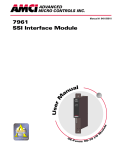
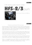
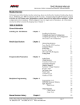
User Manual
2541
High Speed
Programmable Limit
Switch Module
Allen-Bradley
SLC 500 I/O
Module
Manual: 940-05071
GENERAL INFORMA
TION
INFORMATION
Important User Information
The products and application data described in this manual are useful in a wide variety of different applications.
Therefore, the user and others responsible for applying these products described herein are responsible for
determining the acceptability for each application. While efforts have been made to provide accurate information
within this manual, AMCI assumes no responsibility for the application or the completeness of the information
contained herein.
Throughout this manual the following two notices are used to highlight important points.
WARNINGS tell you when people may be hurt or equipment may be damaged if the
procedure is not followed properly.
CAUTIONS tell you when equipment may be damaged if the procedure is not followed
properly.
No patent liability is assumed by AMCI, with respect to use of information, circuits, equipment, or software
described in this manual.
The information contained within this manual is subject to change without notice.
UNDER NO CIRCUMSTANCES WILL ADVANCED MICRO CONTROLS, INC. BE RESPONSIBLE OR
LIABLE FOR ANY DAMAGES OR LOSSES, INCLUDING INDIRECT OR CONSEQUENTIAL DAMAGES
OR LOSSES, ARISING FROM THE USE OF ANY INFORMATION CONTAINED WITHIN THIS
MANUAL, OR THE USE OF ANY PRODUCTS OR SERVICES REFERENCED HEREIN.
Standard Warranty
ADVANCED MICRO CONTROLS, INC. warrants that all equipment manufactured by it will be free from
defects, under normal use, in materials and workmanship for a period of [1] year. Within this warranty period,
AMCI shall, at its option, repair or replace, free of charge, any equipment covered by this warranty which is
returned, shipping charges prepaid, within one year from date of invoice, and which upon examination proves to be
defective in material or workmanship and not caused by accident, misuse, neglect, alteration, improper installation or
improper testing.
The provisions of the “STANDARD WARRANTY” are the sole obligations of AMCI and excludes all other
warranties expressed or implied. In no event shall AMCI be liable for incidental or consequential damages or for
delay in performance of this warranty.
Returns Policy
All equipment being returned to AMCI for repair or replacement, regardless of warranty status, must have a Return
Merchandise Authorization number issued by AMCI. Call (860) 585-1254 with the model and serial numbers
along with a description of the problem. A “RMA” number will be issued. Equipment must be shipped to AMCI
with transportation charges prepaid. Title and risk of loss or damage remains with the customer until shipment is
received by AMCI.
24 Hour Technical Support Number
24 Hour technical support is available on this product. For technical support, call (860) 583-7271. Your call will be
answered by the factory during regular business hours, Monday through Friday, 8AM - 5PM EST. During nonbusiness hours, an automated system will ask you to leave a detailed message and the telephone number that you
can be reached at. The system will page one of two engineers on call. Please have your product model number and
a description of the problem ready before you call.
ADVANCED MICRO CONTROLS INC
ABOUT THIS MANUAL
Introduction
This manual explains the operation, installation, and programming of the 2541 High Speed
Programmable Limit Switch for Allen-Bradley SLC 500™ systems. It is strongly recommended that
you read the following instructions. If there are any unanswered questions after reading this
manual, call the factory. An applications engineer will be available to assist you.
AMCI is a registered trademark of Advanced Micro Controls Inc.
The AMCI is a trademark of Advanced Micro Controls Inc.
SLC and SLC 500 are trademarks of Allen-Bradley Company.
This product incorporates technology which is licensed by Allen-Bradley Company, Inc. AllenBradley has not technically approved, nor does it support this product. All warranty and support for
this product and its application is provided solely by Advanced Micro Controls Inc.
Manuals at AMCI are constantly evolving entities. Your questions and comments on this manual
and the information it contains are both welcomed and necessary if this manual is to be improved.
Please direct all comments to: Technical Documentation, AMCI, 20 Gear Drive, Plymouth Industrial Park, Terryville CT 06786, or fax us at (860) 584-1973.
Revision Record
The following is the revision history for this manual. In addition to the information listed here,
revisions will fix any known typographical errors and clarification notes may be added.
This manual, 940-05071, supersedes 940-05070. The changes reflect the change to the limit switch
output connector from an eight pin green connector to a nine pine black connector. This hardware
change was made to distinguish the LS output connector from the transducer input connector. The
revision was first released April 14, 1999.
Past Revisions
940-05070: Initial Release, 3/31/1999
20 Gear Drive, Plymouth Ind. Park, Terryville, CT 06786
Tel: (860) 585-1254 Fax: (860) 584-1973
1
ABOUT THIS MANUAL
Notes
2
ADVANCED MICRO CONTROLS INC
1
2541 INTRODUCTION
Overview
Until the introduction of AMCI’s PLS modules, interfacing
a high speed programmable limit switch to a SLC 500
programmable controller was a difficult task. Additional
I/O wiring, separate panel mounting, and perhaps even a
custom serial protocol were needed to interface the PLS
and SLC together. A 2541 Resolver PLS module eliminates all of these difficulties. The 2541 plugs into the SLC
500 I/O rack and is under the complete control of processor. All programming is accomplished over the backplane
using the I/O data tables and two M files.
The many features of the 2541 makes it the most advanced
PLS module on the market today.
!
!
!
!
!
!
!
!
!
!
!
Uses a brushless resolver based transducer for position
feedback.
Programmable position resolution from 2 to 4,096 counts
per turn.
Programmable position offset.
Position preset function
Tachometer Scalars allow you to scale the tachometer
value to any meaningful unit of measure, not just RPM.
Six limit switch outputs:
! 100µS update time.
! 100mA @ 28Vdc rated drivers.
! Eight on/off setpoint pairs per output.
Figure 1.1 2541 Module
! Separate on/off automatic advances for speed
compensation.
! Can be programmed as position, timed, or pulsed limit switches
A limit increment/decrement function that allows you to ‘tweak’ limit switch settings on the fly.
Four 30Vdc inputs that allow you to disable the first four outputs based on external conditions.
Two programmable motion detectors that allow you to independently disable any of the outputs
based on machine speed.
Programmable on/off force bits that allow you to set an output to a given state regardless of
programming and conditions.
Extensive fault detection routines continuously monitor the integrity of the module, transducer,
and transducer cabling.
20 Gear Drive, Plymouth Ind. Park, Terryville, CT 06786
Tel: (860) 585-1254 Fax: (860) 584-1973
3
1
INTRODUCTION
Overview (continued)
The 2541 is programmed for the backplane using a combination of I/O data words and two M files.
You can easily read back any data sent to the module. Also, all of the data generated by the module
is reported to the processor. This includes the Position, position offset, and tachometer values as
well as the status of the limit switches, the inputs, and the motion detectors. Therefore you can
report this data to an operator using a remote display, generate other limit switches in ladder logic,
or use this data in any other way appropriate to your machine.
With the use of M files, the SLC processor in the system must be a 5/02 or above.
Fixed SLC systems and 5/01 processors cannot be used. The use of M files also
restricts the 2541 to local or local extended racks. The 2541 cannot be used in a
remote rack.
Programmable Parameters
You configure the 2541 by setting its Programmable Parameters. The programmable parameters
are broken down in the following three groups:
4
!
Module Setup Parameters – Parameters that setup the tachometer, motion detectors, and
active state of the inputs. The output on/off force values are also included in these
parameters.
!
Transducer Setup Parameters – Parameters that affect the position data.
!
Limit Switch Parameters – Parameters that program the type of limit switch and any ANDing
with the motion detectors as well as setpoint and on/off advances.
ADVANCED MICRO CONTROLS INC
1
INTRODUCTION
Module Setup Parameters
Tachometer Response
A bit value that sets how often the 2541 updates the tachometer data to the processor. With a
default of 504 mS, the two choices are 504 mS and 120 mS. Internally, the tachometer updates
every 24 mSec. This update time is used when calculating the limit switch on/off advance values.
Tachometer Scalars
The 2541 allows you to scale the tachometer value reported to the processor. Therefore you can
have the module report a tachometer value scaled to boxes per minute, inches per minute, or any
other meaningful value instead of revolutions per minute. The tachometer is scaled with three
values, Tach Multiplier, Tach Divisor, and Tach Decimal Point. The tachometer reports the rounded
off integer value of the equation:
!
(((Speed[RPM] * Tach Multiplier) / Tach Divisor ) / Tach Decimal Point).
The Tach Multiplier can be any integer between 0 and 1,100. The Tach Divisor can be any integer
between 1 and 63. The Tach Decimal Point can be 1, 10, 100, or 1000. As an example, assume a
speed of 100 RPM, a multiplier of 2, a divisor of 3. The table below shows the different tachometer
values based on the Tach Decimal Point value.
DECIMAL POINT VALUE
1
10
100
1000
Calculated Tach
66.67
6.67
0.67
0.067
Reported Tach
67
7
1
0
Table 1.1 Effect of Tachometer Scalars
When programming the Tach Decimal Point, you will enter a value of 0, 1, 2, or 3 into your
programming data. This corresponds to a Tach Decimal Point value of 1, 10, 100, or 1,000.
Input Active State
These four bit values program the active state of the four inputs on the front of the module. When
an Active State bit is set to its default value of zero, the corresponding input works like a normally
closed relay. The input must have current flowing through it to be deactivated. When an Active
State bits is set to one, the corresponding input works like a normally open contact. The input must
have current flowing through it to be active.
!
If you are not using the inputs, leave the Input Active State bits in their default reset state. The
outputs will then fire without anything attached to the inputs.
Input Forces
You can force any of the four inputs on or off by setting the appropriate bit in the output image
table. A Force OFF bit take precedence over the corresponding Force ON bit.
20 Gear Drive, Plymouth Ind. Park, Terryville, CT 06786
Tel: (860) 585-1254 Fax: (860) 584-1973
5
1
INTRODUCTION
Module Setup Parameters (continued)
Output Forces
You can force any output on or off by setting the appropriate bit in the output image table. A Force
OFF bit take precedence over the corresponding Force ON bit.
!
If your application does not require six limit switch outputs, you can use any uncommitted
limit switch output as a standard DC output by referencing the Force ON bit.
Motion Detector ON/OFF setpoints
The 2541 has two motion detectors, MD1 and MD2, that function as speed based limit switches.
You program a low speed setpoint and a high speed setpoint for each motion detector. If the low
speed setpoint is less than the high speed setpoint then the output will be on when the velocity is
between the two setpoints and off at all other speeds. If the low speed setpoint is greater than the
high speed setpoint then the output will be off when the velocity is between the two setpoints and
on at all other speeds. You can logically AND any limit switch output with either motion detector.
This disables the limit switch unless the machine is running within the programmed range. The
motion detector setpoints are always programmed in RPM, regardless of the values of the Tachometer Scalars. The motion detector setpoints have a range of zero to 32,767 RPM.
The state of the motion detectors is updated when the tachometer value is calculated. Therefore, the motion detectors update every 102 or 504 mS, based on the
value of the Tachometer Response parameter. If you are using the motion detectors
to disable limit switch outputs on a machine that accelerates quickly, you may
have to change the Tachometer Response parameter from its default of 502 mS to
120 mS. This insures that the limit switches will be enabled as quickly as possible
once the machine is at operating speed.
6
ADVANCED MICRO CONTROLS INC
INTRODUCTION
1
Transducer Setup Parameters
Count Direction
A bit value that sets the direction the transducer shaft must rotate to increase the position value. It
defaults to clockwise and can be set to clockwise or counter-clockwise. Note that it is also possible
to reverse the count direction by switching one of the pairs in the transducer cable.
Scale Factor
Sets the position resolution of the 2541 module. It defaults to 4,096 counts per turn and is programmable to any value between 2 and 4,096.
PresetValue
The value that the position data will be set to when you preset it from the backplane. With a default
of zero, it is programmable to any value between 2 and (Scale Factor - 1). See Position Offset below
for more information on how the Preset Value works.
Position Offset
This number is added to the absolute resolver position to calculate the position value of the 2541.
With a default of zero, it is programmable to any value between 2 and (Scale Factor - 1). The
Position Offset give you the ability to set the Position value to any value without rotating the
transducer shaft.
1) Presetting the position forces the module to recalculate the Machine Offset.
2) The 2541 does not store the Position Offset in non-volatile memory but the
value is placed in its M0 file and available to the processor as a data word. In
order to keep the position value absolute, you must store the Position Offset in
an integer file and write it down to the 2541 every time you configure the
module. If you do not do this, you will have to reset the machines position
every time you cycle power.
20 Gear Drive, Plymouth Ind. Park, Terryville, CT 06786
Tel: (860) 585-1254 Fax: (860) 584-1973
7
1
INTRODUCTION
Limit Switch Parameters
Limit Switch Type Parameter
Programs the type of limit switch the output channel will be. The three choices are Normal, Timed,
and Pulse. Normal outputs turn on and off based on position. Timed outputs function like a timing
relay, turning on at a programmed position and remaining on for a programmed length of time.
Pulse outputs generate a pulse train between two position values.
Motion ANDing Parameter
You can disable the a limit switch output by ANDing it with one of the two motion detectors. This
prevents the output from firing until the machine is running within the range set by the motion
detector. This parameter specifies which motion detector is ANDed with the limit switch output.
You can also choose not to AND the output with either motion detector.
Limit Switch ON / OFF Setpoints
Limit switch setpoints are pairs of position values that set where the outputs turn on and off.
Setpoints can be programmed to any value between zero and (Scale Factor - 1).
Normal Limit Switch – Eight pairs of ON / OFF setpoints that give you the ability to turn the
output on and off eight times per turn. If the ON setpoint is less than the
OFF setpoint, the output is on when the position value is between the two
limits and off when outside the limits. If the ON setpoint is greater than the
OFF setpoint, the output is off when the position value is between the two
limits and on when outside the limits.
Pulse Limit Switch – One ON / OFF setpoint pair that sets the leading edge of the first pulse in the
train and the trailing edge of the last pulse in the train. Two additional
parameters set the total number of pulses in the train and the number of
counts that each pulse is on.
Timed Limit Switch – One ON / OFF setpoint pair that sets the ON position and off position of the
limit. A third parameter sets the amount of time the output is on. Usually,
the output will turn on at the ON setpoint and remain on for the specified
length of time. However, if the OFF setpoint is reached before the output
times out, then the output will turn off. The maximum length of time an
output can be on is 9.999 seconds.
Limit Switch ON / OFF Advances
Two parameters that allow the limit switch channel to compensate for fixed delays in the system by
turning on or off before or after the actual programmed setpoint. The maximum compensation is
±99.9 mSec. Setting the Advance to a positive value will force the output to turn on at an earlier
position. Setting the Advance to a negative value will force the output to turn on at a later position.
8
ADVANCED MICRO CONTROLS INC
2
INSTALLATION
This chapter describes how to install a Series 8500 system. It covers module, transducer,
and relay board installation and the cabling needed to connect the components together.
System Requirements
Processor Requirements
A 2541 uses a M0 and M1 files to communicate with the processor. Therefore the processor used in
your system must be a 5/02 or greater. Fixed SLC and 5/01 processors cannot be used with the 2541
module.
Rack Requirements
A 2541 must be installed in a local or expanded local rack. Note that the 2541 cannot be installed
the processor slot of the expanded local rack. The module cannot be installed in a remote rack
because of the use of the M files.
Power Requirements
A 2541 module draws its power from the I/O rack +5Vdc
and +24Vdc supplies. The maximum current draw from
the +5Vdc supply is 0.195 amps, (0.98 W). The maximum
current draw from the +24Vdc supply under normal
operating conditions is 0.035 mA, (0.84 W). If the
reference voltage generated by the module is shorted, the
current draw from the +24Vdc supply rises to 0.15A,
(3.6W) while the power draw on the +5Vdc supply
remains the same. Add these power requirements to the
requirements of all the other modules in the rack when
sizing the power supply.
2541 Connectors
Figure 4.1 shows the placement of the I/O and Transducer
Input Connectors on the 2541.
Status LEDs
Shows output and
module status.
Input LEDs
RESOLVER
PLS
1
4
2
5
3
6
2541
Shows active state
of the four inputs.
DC Input
Connector
For the output
disable inputs.
Pin 1 on Top
LS Output
Connector
Pin 1 on Top
Transducer Input
Connector
The mates of the Transducer Input and LS
Pin 1 on Bottom
Output Connectors can be plugged into
Figure 4.1 2541 Connectors
the wrong connector. Crossing these
connections can damage the module if DC
power for the limit switches is instead applied
to the Transducer Input Connector. Check all
wiring before applying power to the 2541.
20 Gear Drive, Plymouth Ind. Park, Terryville, CT 06786
Tel: (860) 585-1254 Fax: (860) 584-1973
9
2
INSTALLATION
Installing the Module
Remove system power before removing or installing any module in an I/O
rack. Failure to observe this warning may result in damage to the module’s
circuitry and/or undesired operation with possible injury to personal.
1) Align the modules’ right circuit board with the top and bottom card guides in the rack.
2) Gently slide the module into the rack until the top and bottom latches secure the module in place.
To remove the module, depress the top and bottom latches and slide the module out of the rack.
Module ID Code
All 2541s have an ID Code of 9935. This reserves 8 Input and 8 Output words for the module.
When configuring the slot you must also enter the ‘SPIO CONFIG’ menu and specify a M0 File size
of 120 words and a M1 File size of 650 words. If you do not configure the M files correctly you will
get an error message when you switch the processor to Run Mode. The error message is “M1/M0
File Configuration Error, slot X” were “X” is the slot the 8500 plugs into. If you are using AI
software, you must use version 8.15+ to program the M file lengths correctly.
Status LED’s
The front display has a total of eight LED’s. The six that are numbered are status LED’s for the six
outputs. When external power is supplied, these LED’s will light when the corresponding output is
on. The other two, labeled ‘RUN’ and ‘FLT’ indicate the operating status of the module.
RUN
FLT
OFF
ON
COMMENT
MODULE FAULT
The module failed its power-up diagnostics. Cycle power to the module. If the error
still exists, the module must be returned to AMCI for repair.
ON
ON
NON CLEARABLE TRANSDUCER FAULT
There is a transducer fault that the module cannot clear. There are six major causes
of this fault.
!"Broken or intermittent transducer cable
!"Non-compatible transducer
!"Improper wiring of the transducer cable
!"Improper installation of the transducer cable
!"Faulty transducer
!"Faulty module
ON
FLASHING
CLEARABLE TRANSDUCER FAULT
There is a transducer fault that can be cleared with a Clear Errors command from the
backplane. A transducer fault of this type is most often caused by a burst of electrical
noise, an intermittent connection, or a mis-wired transducer cable.
ON
OFF
MODULE OK
The module is operating without any faults. The transducer is operating properly.
Table 2.1 Status LED’s
10
ADVANCED MICRO CONTROLS INC
2
INSTALLATION
Transducer Input Connector
The Transducer Input Connector has eight contacts. The mating connector for the 2541 is not
supplied with the module. It comes as part of an AMCI pre-assembled transducer cable or it can be
ordered as a separate item. See figure 2.3, C1TP-(x) Wiring Diagram below for the mating connector
part numbers.
Figure 2.2 shows the connector pin out to industry standard wire designations.
8
7
6
5
4
3
2
1
! R1/R2 – Reference Winding
S3
S1
! S1/S3 – COS Winding
S4
! S2/S4 – SIN Winding
S2
All Shields
No Connection
R2
R1
Figure 2.2 Transducer Input Connector
Transducer Cable Installation
Pre-assembled and tested cables are available from AMCI under the part number C1TP-(x), where (x)
is the length in feet. Figure 2.3 is a wiring diagram of the C1TP-(x) cable.
1) Resolvers are low voltage, low power devices. If you are using A-B guidelines
for cabling installation, treat the transducer cable as a Category 2 cable. It can
be installed in conduit along with other low power cabling such as communication cables and low power ac/dc I/O lines. It cannot be installed in conduit
with ac power lines or high power ac/dc I/O lines.
2) The shields of the transducer cable must be grounded at the 2541 module
only! When installing the cable, treat the shield as a signal conductor. Do not
connect the shield to ground at any junction box or the transducer. This will
eliminate ground loops that could damage the module or SLC.
Transducer
Connector
BLK
WHT
S3
S1
S4
6
S2
5
Shields
4
8
7
GRN
E
AMCI Part #: MS-16
Bendix #:
MS3106A16S-1S
D
BLK
F
G
C
SHIELDS
A
3
R2
1 R1
RED
BLK
2
B
Module Connector
Mates to all Single Channel Resolver Input
and Limit Switch Modules.
AMCI Part #: MS-8P
Phoenix #: MC1.5/8-ST-3.81
1803633
BELDEN 9873 Cable
For Cable lengths greater than
100’ (30 meters) use BELDEN 9730.
Figure 2.3 C1TP-(x) Wiring Diagram
20 Gear Drive, Plymouth Ind. Park, Terryville, CT 06786
Tel: (860) 585-1254 Fax: (860) 584-1973
11
2
INSTALLATION
Transducer Specifications
The following table contains mechanical and environmental specifications for all of the AMCI
rotary position transducers that are compatible with the 2541.
Specification
Shaft Diameter
Radial Shaft Loading
Axial Shaft Loading
Starting Torque
Moment of Inertia
Weight
Enclosure
All HT-20 s
All H25 s
0.625"
0.375"
40 lbs. Max.
400 lbs. Max.
200 lbs. Max.
HT-6
0.188"
8 lbs. Max.
4 lbs. Max.
20 lbs. Max.
8 oz.in. @ 25 C
1.5 oz.in. @ 25 C
20 oz-in-sec†
4 oz-in-sec
2.1 x 10 oz-in-sec†
4 lbs.
1 lb.
0.7 lb.
NEMA 13 or 4X
NEMA 4
NEMA 13
2
0.5 oz.in. @ 25 C
-4
Environmental (All Transducers)
Operating Temp
-20 to 125 C
Shock
50G s for 11 mSec
Vibration
5 to 2000 Hz @ 20 G s
Table 2.2 Transducer Specifications
F
A
G
E
D
B
C
All of the AMCI transducers that are compatible with the
S1 (RED)
S3 (BLK)
2541 have the same connector. The connector pin out to
R1 (RED/WHT) industry standard wire designations is given in figure 2.4.
R2 (BLK/WHT)
S2 (YEL)
S4 (BLU)
Figure 2.4 Transducer Connector Pin Out
Transducer Mounting
All AMCI resolver based transducers are designed to operate in the industrial environment and
therefore require little attention. However, there are some general guidelines that should be
observed to ensure long life.
!
Limit transducer shaft loading to the following maximums:
Radial Load
Axial Load
All HT-20 Transducers
100 lbs. (445 N)
50 lbs. (222 N)
All H25 Transducers
30 lbs. (133 N)
15 lbs. (66.7 N)
All Other Transducers
4 lbs. (17.8 N)
2 lbs. (8.9 N)
Table 2.3 Transducer Bearing Loads
12
ADVANCED MICRO CONTROLS INC
2
INSTALLATION
Transducer Mounting (continued)
!
Minimize shaft misalignment when direct coupling shafts. Even small misalignments produce
large loading effects on front bearings. It is recommended that you use a flexible coupler
whenever possible.
!
The transducer housing must be connected to Earth Ground. This is usually accomplished
through its mounting. If not properly grounded through its mounting, run a heavy guage wire
from the transducer housing to an Earth Ground point as close as possible to the transducer.
Transducer Outline Drawings
AMCI offers a broad line of resolver based transducers for use with the 2541 module. Outline
drawings of selected transducer are included here in the manual. Listed below are the transducer
outline drawings that are not included. Contact AMCI if you need one of these outline drawings.
They will be faxed to you upon request.
!
!
!
!
!
R11X-J10/7 ............
R11X-J12/7 ............
HT-6 .......................
HT-20C ...................
H25FL & H25SL ....
NEMA 1 Size 11 Resolver, 0.120” Shaft
NEMA 1 Size 11 Resolver, 0.188” Shaft
NEMA 13 R11X-J12/7 Resolver
NEMA 4X Stainless Steel Transducer
NEMA 4 Size 25 Transducers, Integral Cable
HT-20: Anodized Aluminum Body, 1070 Steel Shaft, NEMA 13
2.500"
4.75"
(63.5)
(120.7)
KEYWAY
2.000"
(50.8)
.106(2.69)
.1885(4.79)
DEEP X 1.0(25.4)
X
.108(2.74)
.1895(4.81)
1.000"
0.750"
3.250"
(19.05)
(82.6)
0.500"
(12.7)
KEY
(25.4)
.187(4.75)
SQ. X 1.0(25.4)
.188(4.78)
1.000"
(25.4)
2.500" 2.000"
(63.5)
(50.8)
1.180 Dia.
1.500"
(30)
(38.1)
0.250"
(6.35)
0.6247" (15.87)
0.6237" (15.84)
0.250"
0.150"
(6.35)
(3.81)
1/4-20 UNC-2B
0.500"(12.7) DEEP
8 PLACES
1.25"
(31.8)
MS3102E16S-1P
CONNECTOR
0.700" (17.78) MAX.
TOTAL CLEARANCE OF 3.5"(89)
NEEDED FOR REMOVAL OF
MATING CONNECTOR
Figure 2.5 HT-20 Outline Drawing
20 Gear Drive, Plymouth Ind. Park, Terryville, CT 06786
Tel: (860) 585-1254 Fax: (860) 584-1973
13
2
INSTALLATION
AMCI Transducer Outline Drawings (continued)
HT-20S: Anodized Aluminum Body, 1070 Steel Shaft, NEMA 13
2.500"
4.75"
(63.5)
(120.7)
0.600" (15.24)
MAX.
2.000"
(50.8)
KEYWAY
1.000"
.1885(4.79)
.106(2.69)
DEEP X 1.0(25.4)
X
.1895(4.81)
.108(2.74)
(25.4)
0.750"
3.250"
(19.05)
(82.6)
0.500"
(12.7)
KEY
.187(4.75)
SQ. X 1.0(25.4)
.188(4.78)
1.000"
(25.4)
2.500" 2.000"
(63.5)
(50.8)
0.250"
1.180 Dia.
1.500"
(30)
(38.1)
(6.35)
0.6247" (15.87)
0.6237" (15.84)
0.250"
0.150"
(6.35)
(3.81)
MS3102E16S-1P CONNECTOR
TOTAL CLEARANCE OF 3.5"(89) NEEDED
FOR REMOVAL OF MATING CONNECTOR
1/4-20 UNC-2B
0.500"(12.7) DEEP
8 PLACES
1.25"
(31.8)
Figure 2.6 HT-20S Outline Drawing
HT-20K: Hard Coat Anodized Aluminum Body, Stainless Steel Shaft, NEMA 4X
2.500"
(63.5)
HT-20K SUPPLIED WITH VITON SHAFT SEAL
HT-20L SUPPLIED WITH NITRILE SHAFT SEAL
4.75"
(120.7)
KEYWAY
2.000"
(50.8)
.106(2.69)
.1885(4.79)
DEEP X 1.0(25.4)
.1895(4.81) X .108(2.74)
1.000"
0.750"
3.250"
(19.05)
(82.6)
0.500"
(12.7)
KEY
(25.4)
.187(4.75)
SQ. X 1.0(25.4)
.188(4.78)
1.000"
(25.4)
2.500" 2.000"
(63.5)
(50.8)
1.180 Dia.
1.500"
(30)
(38.1)
0.250"
(6.35)
0.6247" (15.87)
0.6237" (15.84)
MS3102E16S-1P
CONNECTOR
0.250"
(6.35)
1/4-20 UNC-2B
0.500"(12.7) DEEP
8 PLACES
1.25"
(31.8)
0.700" (17.78) MAX.
TOTAL CLEARANCE OF 3.5"(89)
NEEDED FOR REMOVAL OF
MATING CONNECTOR
Figure 2.7 HT-20K Outline Drawing
14
ADVANCED MICRO CONTROLS INC
2
INSTALLATION
Transducer Outline Drawings (continued)
H25SE & H25FE: Anodized Aluminum Body, 1070 Steel Shaft, NEMA 4
#8-32 UNF 2B THD X
0.18 (4.57) MIN DEPTH 6 PLACES
60 APART ON A 1.875 ( 47.63) B.C.
0.300
MS3102E16S-1P
CONNECTOR
(7.62)
0.3747 (9.52)
0.3744 (9.51)
2.31 (58.7)
DIA
H25SE
Servo Mount
End Connector
0.875 –0.025
(22.23–0.64)
0.100 (2.54)
0.100 (2.54)
1.250 (31.75)
1.249 (31.72)
2.50 (63.5)
3.20 (81.3) MAX
Additional 3.5 (89) clearance
needed for mating connector
removal.
2.65 (67.3)
0.250 (6.35)
1.032 (26.21)
TYP
1.032 (26.21)
TYP
0.300
MS3102E16S-1P
CONNECTOR
(7.62)
2.65 (67.3)
0.3747 (9.52)
0.3744 (9.51)
H25FE
Flange Mount
End Connector
1.250 (31.75)
1.249 (31.72)
0.875 –0.025
(22.23–0.64)
0.218 (5.54) DIA
4 PLACES
Figure 2.8 H25FE and H25SE Outline Drawing
20 Gear Drive, Plymouth Ind. Park, Terryville, CT 06786
Tel: (860) 585-1254 Fax: (860) 584-1973
15
2
INSTALLATION
Transducer Outline Drawings (continued)
H25SS & H25FS: Anodized Aluminum Body, 1070 Steel Shaft, NEMA 4
MS3102E16S-1P
CONNECTOR
#8-32 UNF 2B THD X
0.18 (4.57) MIN DEPTH 6 PLACES
60 APART ON A 1.875 ( 47.63) B.C.
2.65 (67.3) MAX
0.300
Additional 3.5 (89)
clearance needed
for mating connector
removal.
(7.62)
0.3747 (9.52)
0.3744 (9.51)
2.31 (58.7)
DIA
H25SS
Servo Mount
Side Connector
0.875 –0.025
(22.23–0.64)
0.100 (2.54)
0.100 (2.54)
1.250 (31.75)
1.249 (31.72)
2.50 (63.5)
2.70 (68.6) MAX
MS3102E16S-1P
CONNECTOR
2.65 (67.3) MAX
Additional 3.5 (89)
clearance needed
for mating
connector
removal.
0.300
(7.62)
2.65 (67.3)
0.3747 (9.52)
0.3744 (9.51)
H25FS
Flange Mount
Side Connector
1.250 (31.75)
1.249 (31.72)
1.032 (26.21)
TYP
0.875 –0.025
(22.23–0.64)
1.032 (26.21)
TYP
2.65 (67.3)
0.218 (5.54) DIA
4 PLACES
0.250 (6.35)
2.65 (67.3) MAX
Figure 2.9 H25SS and H25SS Outline Drawing
16
ADVANCED MICRO CONTROLS INC
2
INSTALLATION
Input Wiring
Input Connector
Figure 2.10 shows the pin out of the Input Connector and a simplified schematic of the Input 1. The
schematics for the other inputs is identical. Note that pin one is at the top of the connector when
plugged into the module, not at the bottom as it is with the Transducer Input Connector.
Input LED’s
GRN
RED
Optocoupler
1
2
3
4
5
Input 1
Input 2
Input 3
Input 4
Input Common
Figure 2.10 Input Connector Pin Out
Input LED’s
There are eight LED’s above the Input Connector that show the on/off status of the inputs. There are
two LED’s for each input. The LED that lights is dependent on how the inputs are wired, either as
sinking or sourcing inputs.
Because the inputs share a single common, they must be all wired as the same type
of input, either sinking or sourcing.
Sinking Inputs (Red)
Input 1 ON
Input 2 ON
Input 3 ON
Input 4 ON
Sourcing Inputs (Green)
Input 1 ON
Input 2 ON
Input 3 ON
Input 4 ON
Figure 2.11 Input LED’s
20 Gear Drive, Plymouth Ind. Park, Terryville, CT 06786
Tel: (860) 585-1254 Fax: (860) 584-1973
17
2
INSTALLATION
Input Wiring (continued)
Connector Wiring
Figure 2.12 shows how to wire the inputs as sourcing inputs. Wiring them as sinking inputs only
involves switching the positive and negative power supply leads. Note that you cannot wire one
input as a sourcing input and another as a sinking input. Because they share a common pin, they
must all be wired as the same type.
The figure assumes that relays are used to activate the inputs. The note on setting the Input Active
State parameters assumes that you want the limit switch output active when the relay is in it unpowered state. If you want the limit switch outputs active when the relays are powered, use the
other state of the bit when programming the Input Active state parameters.
Shielded cable should be used to help with noise immunity. Treat the shield as a
signal carrying conductor and ground it only at the power supply. Do not ground
the shield at junction boxes or the 2541 module. This will help to eliminate
potential ground loops in your system.
Shield
1
POWER
SUPPLY
8-24 Vdc
Input requires a minimum of
5mA to activate.
+
Input Electrical Specs
Voltage Differential
(Common to Input or
Input to Common)
Logic 0 = 0 to 2Vdc
Logic 1 = 8 to 30 Vdc
2
3
4
5
When using a Normally Open contact to activate the input,
program the corresponding Input Active State bit to ’0’.
to enable the output when the relay is off.
When using a Normally Closed contact to activate the input,
program the corresponding Input Active State to ’1’
to enable the output when the relay is off.
Figure 2.12 Input Wiring
18
ADVANCED MICRO CONTROLS INC
2
INSTALLATION
Output Wiring
Output Connector
Figure 2.13 shows the pin out of the LS Output Connector and a simplified schematic of Output 1.
The schematic for the other outputs is identical. Note that pin one is at the top of the connector, not
at the bottom as it is with the Transducer Input Connector.
1 No Connection
2 +Vdc IN
Flyback
3 COMMON
Diode
Output Voltage: 8 to 28 Vdc
4 Output 1
5 Output 2
Output Current: 150 mA per
6 Output 3
output @ 60°C
7 Output 4
8 Output 5
Status
9 Output 6
LED
Figure 2.13 LS Output Connector Pin Out
The Flyback Diode is built-in protection for the driver againist voltage spikes from mechanical
relays or other inductive loads. However, you should still install a surge suppression device across
any inductive load attached to the 2541. This will greatly decrease the amount of electrical noise
generated by the load when it turns on and off. Note that your power supply must be attached to the
+Vdc IN and COMMON terminals of the connector for the Flyback Diode to work properly.
The Status LED is one of the six numbered LED’s on the front panel. It will turn on when the LS
Output is on and your power supply is attached to the +Vdc IN and COMMON terminals of the
connector.
Connector Wiring
Figure 2.14 shows how to wire an output. The other five outputs are wired identically. Note that a
single power supply must be used to power all of the outputs because they share power supply
connections.
All power suppluy connections to the loads must be
Power Supply
8-24 Vdc
+
If the power supply is
to be earth grounded,
make the connection
as close to the supply
as possible.
Use 14 AWG min. wire
for the power supply
connections.
made as close to the power supply as possible. This
limits the amount of electrical noise induced from one
load into another.
1 No Connection
1
2
2 +Vdc IN
3
3 COMMON
4
4 Output 1
LOAD 1
5
5 Output 2
6
6 Output 3
7
7 Output 4
LOAD 2
8
8 Output 5
9
9 Output 6
All inductive loads must have surge surge suppression
devices installed across thier terminals. This limits the
amount of electrical noise generated by the load.
20 Gear Drive, Plymouth Ind. Park, Terryville, CT 06786
Tel: (860) 585-1254 Fax: (860) 584-1973
Figure 2.14 Limit Switch Output Wiring
19
2
INSTALLATION
Notes
20
ADVANCED MICRO CONTROLS INC
3
BACKPLANE PROGRAMMING
A 2541 module communicates with the SLC processor through two ‘M’ files as well as
the Output and Input Image Tables. The 2541 is configured with data stored in its M0
and M1 data files. The Output Image Table is used to quickly adjust limit switch
setpoints and force the module’s I/O on or off. The Input Image Table is used to
transmit position, tachometer, and limit switch status as well as global error information.
This chapter details how to use this data to configure and run the 2541 module.
File Addressing
In this chapter, file addresses are defined in the following manner:
I:X.n
O:X.n
M0:X.n
M1:X.n
Input Image Table
Output Image Table
M0 file
M1 file
Where: ‘X’ is the slot number of the 2541 and ‘n’ is the word number in the file. When referring to
a specific bit in a word, the characters “/bb” will be appended where ‘bb’ is the bit address.
The M0 file has a total lenght of 120 words, and the M1 file has a total length of 650 words. If you
are using AI software, you must use version 8.15+ to program the M file lengths correctly.
Programming Cycle
Programming changes are written to the module with a Programming Cycle. All parameters, except
for I/O Forces, are programmed through Programming Cycles. Programming Cycles are controlled
with a Transmit Bit and associated Acknowledge Bit. In order to simplify programming, the
Programmable Parameters are broken down into two groups. Therefore, there are two Transmit /
Acknowledge Bit pairs that control the three Programming Cycle that setup the module. A third
Transmit / Acknowledge Bit pair controls the Limit Switch Increment / Decrement Programming
Cycle.
A Programming Cycle consists of six steps.
1) Write the new data in the correct memory locations. The programming data is stored in one
of the two M files or the Output Image Table.
2) Set the appropriate Transmit Bit. The 2541 will not act on the new programming data until
the Transmit bit is set.
3) Once the 2541 is done with the programming data it will set the appropriate Acknowledge Bit
and any necessary error bits.
4) Once your ladder logic sees the Acknowledge Bit set, check for any errors.
5) Reset the Transmit Bit after you’ve responded to any errors.
6) The 2541 responds by resetting the Acknowledge Bit. The Programming Cycle is complete.
20 Gear Drive, Plymouth Ind. Park, Terryville, CT 06786
Tel: (860) 585-1254 Fax: (860) 584-1973
21
3
PROGRAMMING
Programming Groups
I/O Forces
I/O Forces are stored in the Output Image Table. The 2541 acts on these bits continuously. If one of
these bits is set, the module will force the associated input or output within one processor scan time.
Setup Data: M0:X.0 – M0:X.19
All Transducer Setup Parameters and all Module Setup Parameters except for I/O Forces are stored
in the M0 file between addresses M0:X.0 and M0:X.19. M0:X.0/15 is the Transmit Bit for this
programming group. I:X.0/13 is the Acknowledge bit for this programming group.
Limit Switch Data: M1:X.0 – M0:X.629
All Limit Switch Setup Parameters are stored in the M1 file between addresses M1:X.0 and
M1:X.629. M1:X.0/15 is the Transmit Bit for this programming group. I:X.0/15 is the Acknowledge bit for this programming group.
LS Increment / Decrement Data: O:X.0
This word in the Output Image Table give you the ability to increment or decrement limit switch
setpoints while the machine is running to fine tune limit switch settings. O:X.0/15 is the Transmit
Bit for the LS Increment / Decrement Data. I:X.0/12 is the Acknowledge Bit for the LS Increment /
Decrement Data.
Error Handling
The 2541 stops accepting new parameters once it sets a programming error bit. How you respond to
the error depends on your application. However, to reset the programming error in the 2541 you
must go through a Programming Cycle with a Clear Errors bit set. Each programming group has a
Clear Error bit that acts globally. Setting any of these bits will clear all of the errors in the module.
Consider using the Clear Error bit in the Output Image Table. You do not need to write down any
additional programming data when using this Clear Errors bit which give you the ability to write a
single “Clear Errors” Programming Cycle that can be used at any time.
22
ADVANCED MICRO CONTROLS INC
3
PROGRAMMING
Input Image Table
Figure 3.1 shows the format of the Input Image Table data. I:X.0 contain Error and Acknowledge
Bits. The other data words contain position and tachometer data as well as limit switch and Real
Input status data.
Input Image Table
Word 1
Machine Position Data
Word 2
Tachometer Data (Scaled Value)
Word 3
Word 4
Word 5
RESERVED: Set to zero.
0
SUFlt
LSFlt
I/DSet
I/DNum
MsgIgn
TrFlt
ModErr
MD1
MD2
0
TachOv
I/DAck
0
SUAck
Word 0
LSAck
15 14 13 12 11 10 09 08 07 06 05 04 03 02 01 00
LS Output Status
LS6 LS1
RESERVED: Set to zero.
RESERVED: Set to zero.
Input Status
IN4 IN1*
Word 6
RESERVED: Set to zero.
Word 7
RESERVED: Set to zero.
Bit 0 = LS1, Bit 1 = LS2,
Bit 4 = LS5, Bit 5 = LS6
* Bit 0 = IN1, Bit 1 = IN2, Bit 2 = IN3, Bit 3 = IN4
Figure 3.1 Input Image Table Data Format
Status Bits
SUErr: Setup Error, I:X.0/00. Because parameter values are not stored in non-volatile memory,
this bit is set on every power up. It is also set if there is an error in the setup programming
data, M0:X.0 – M0:X.19, after a Programming Cycle tries to set these parameters. If this bit
is set after a Programming Cycle, status bits in M0:X.100 – M0:X.109 show the exact error.
LSErr: Limit Switch Error, I:X.0/02. This bit is set if there is an error in the limit switch programming data, M1:X.0 – M1:X.629, after a Programming Cycle tries to set these parameters.
Status bits in M1:X.630 – M0:X.649 show the exact error.
I/DNum: Inc/Dec Output Number Error, I:X.0/03. Set when the number of the Limit Switch
output being incremented or decremented is invalid. Also set if you do not specify which
setpoint, or both, of the setpoint pair you wish to change.
I/DSet: Inc/Dec Output Setpoint Error, I:X.0/04. Set when the limit switch output setpoint
being incremented or decremented is invalid.
20 Gear Drive, Plymouth Ind. Park, Terryville, CT 06786
Tel: (860) 585-1254 Fax: (860) 584-1973
23
3
PROGRAMMING
Input Image Table (continued)
Status Bits (continued)
MsgIgn: Message Ignored, I:X.0/05. Set when you attempt to program any parameter, except I/O
Forces, and a programming error exists.
ModFlt: Module Fault, I:X.0/06. The 2541 failed its power up self test. Cycle power to the
module. If the fault remains, the 2541 must be returned to AMCI for repairs.
TrFlt:
Transducer Fault, I:X.0/07. Set when there is a transducer fault. Most common causes
are the transducer not being attached or faulty transducer cabling.
MD1:
Motion Detect 1, I:X.0/08. Set when the transducer velocity, in RPM, is within the
setpoints programmed into Motion Detector 1.
MD2:
Motion Detect 2, I:X.0/09. Set when the transducer velocity, in RPM, is within the
setpoints programmed into Motion Detector 2.
TachOv: Tachometer Overflow, I:X.0/10. Set when the scaled tachometer data in I:X.2 exceeds
32,767. Above this value, the SLC interprets the data as a negative value.
I/DAck: Limit Switch Increment /Decrement Acknowledge Bit, I:X.0/12.
SUAck: Setup Programming Acknowledge Bit, I:X.0/13.
LSAck: Limit Switch Programming Acknowledge Bit, I:X.0/15.
Output Image Table
The Output Image Table data is used to do the following:
24
!
Word O:X.0 is used to increment or decrement limit switch setpoints. This gives you the
ability to fine tune the setpoints while the machine is running.
!
Words O:X.1 and O:X.3 are used to force any limit switch output on or off. You force an
output by setting the appropriate bit. Force OFF bits take precedence over Force ON bits. For
normal operation, these two words should equal 0000h.
!
Words O:X.6 and O:X.7 are used to force the Real Inputs on or off. You force an input by
setting the appropriate bit. Force OFF bits take precedence over Force ON bits. For normal
operation, these two words should equal 0000h.
ADVANCED MICRO CONTROLS INC
3
PROGRAMMING
Output Image Table (continued)
Figure 3.2 shows the format of the Output Image Table data.
Output Image Table
Word 1
Word 2
Word 3
CgON
I/DSP
CgOFF
ClrErr
I/DTMT
15 14 13 12 11 10 09 08 07 06 05 04 03 02 01 00
INC/DEC
INC/DEC
Setpoint
0
0 0 0 LS
Word 0
Number
Number
RESERVED: Set to zero.
Force ON Bits
LS6 LS1
RESERVED: Set to zero.
RESERVED: Set to zero.
Force OFF Bits
LS6 LS1
Word 4
RESERVED: Set to zero.
Word 5
RESERVED: Set to zero.
Word 6
RESERVED: Set to zero.
Word 7
RESERVED: Set to zero.
Force OFF
IN4 IN1
Force ON
IN4 IN1
Figure 3.2 Output Image Table Data Format
Status Bits
INC/DEC LS Number: O:X.0/02 – O:X.0/00. These three bits make up a binary number that is
the number of the limit switch whose setpoints you want to change. The min/max. values
are one and six. Setting these bits to a limit switch number that does not exist will result
in an error. The error bit set is I/DNum, I:X.0/03.
INC/DEC Setpoint Number: O:X.0/09 – O:X.0/06. These four bits make up binary number that is
the number of the setpoint pair you wish to adjust. Range of values is 1 to 9. Set these
bits to 9 to change all of the setpoint pairs programmed on the output. Setting this
number to 0, or greater than 9, or to a setpoint pair that is not programmed, will generate
an error. The error bit set is I/DSet, I:X.0/04.
CgON:
Change ON Setpoint, O:X.0/10. Set this bit to change the ON setpoint of the selected
ON/OFF setpoint pair(s). This bit and the CgOFF bit can be set at the same time.
CgOFF: Change OFF Setpoint, O:X.0/11. Set this bit to change the OFF setpoint of the selected
ON/OFF setpoint pair(s). This bit and the CgON bit can be set at the same time.
I/DSP:
INC/DEC Setpoint, O:X.0/12. Set this bit to ‘0’ to increment the selected setpoint(s).
Set this bit to ‘1’ to decrement the selected setpoint(s).
ClrErr:
Clear Error Bit, O:X.0/14. When set to ‘1’, the 2541 will clear all programming errors. It
will also attempt to clear the transducer fault if one exists.
I/DTMT: Increment / Decrement Transmit Bit, O:X.0/15.
20 Gear Drive, Plymouth Ind. Park, Terryville, CT 06786
Tel: (860) 585-1254 Fax: (860) 584-1973
25
3
PROGRAMMING
M0 File
The M0 File is broken down into two sections.
Setup Programming Data: M0:X.0 to M0:X.19. Used to preset the Machine Position as well as
program all Transducer Setup Parameters and Module Setup Parameters except for the I/O Forces.
Setup Status Data: M0:X.100 to M0:X.109. Contains status data on the last Setup Programming
Cycle.
M0 File / Setup Programming Data
Figure 3.3 shows the format of the Setup Programming Data. Word M0:X.0 contains bit value
parameters, a Clear Errors bit and a transmit bit. The other words in the data contain the rest of the
programmable parameters.
M0 File / Setup Data
Word 1
Scale Factor (2 to 4,096)
Word 2
Preset Value (0 to SF-1)
Word 3
Machine Offset (0 to SF-1)
Word 4
Motion Detector 1 Low RPM (0 to 32,767)
Word 5
Motion Detector 1 High RPM (0 to 32,767)
Word 6
Motion Detector 2 Low RPM (0 to 32,767)
Word 7
Motion Detector 2 High RPM (0 to 32,767)
Word 8
RESERVED: Must equal 000h
Word 9
Tach Multiplier (0 to 1,100)
Input Active
State
Word 10
Tach Divisor (0 to 63, 0 only if Tach Mul. = 0
Word 11
Tach Decimal Point (0 to 3, Divide by 10(DP))
Words 12 19
ClrErr
0 0
Preset
CDir
0 0 0 0 0 0 0 0 0
TRsp
Word 0
SDTMT
15 14 13 12 11 10 09 08 07 06 05 04 03 02 01 00
RESERVED: Must equal 0000h
In order to keep the Machine Position absolute, the Machine
Offset must be set equal to the value stored in M0:X.101 before
setting the Setup Data Transmit Bit.
Bit 0 = IN1, Bit 1 = IN2, Bit 2 = IN3, Bit 3 = IN4
Resetting the bit to ’0’ makes the input act like a normally closed relay.
Setting the bit to ’1’ makes the input act like a normally open relay.
Figure 3.3 Setup Programming Data Format
26
ADVANCED MICRO CONTROLS INC
3
PROGRAMMING
M0 File / Setup Programming Data (continued)
Status Bits
ClrErr: Clear Errors, M0:X.0/00. When set to ‘1’, the 2541 will clear all programming errors. It
will also attempt to clear the transducer fault if one exists.
Preset: Preset Machine Position, M0:X.0/01. Set to ‘1’ to preset the Machine Position to the
Preset Value in word M0:X.2.
CDir:
Count Direction, M0:X.0/04. Set to ‘0’ for CW increasing position count when the
transducer cable is wired as specified in this manual. Set to ‘1’ for CCW increasing
position count. Note that is also possible to reverse count direction by reversing a pair of
wires in the transudcer cable.
TResp: Tach Response, M0:X.0/05. Set to ‘0’ for 504 mSec update time. Set to ‘1’ for 120
mSec update time. This update time applies to the tachometer data reported over the
backplane and the ON/OFF status of the motion detectors.
SDTMT: Setup Data Transmit, M0:X.0/15.
M0 File / Setup Status Data
Figure 3.4 shows the format of the Setup Status Data. Word M0:X.100 contains detailed status bits
of the last Setup Programming Cycle. A general error bit in the Input Image Table, SUErr,
I:X.0/00, is set on any error in the Setup Programming Data. Your ladder logic should check this
error bit first. If it is set, word M0:X.100 will set bits that help you pinpoint the error.
Word M0:X.101 is the calculated Machine Offset. This value changes every time the machine
Position is preset. In order to keep the Machine Position absolute, you must copy this value into
the Machine Offset word, M0:X.3, in the Setup Programming Data before performing a Setup
Programming Cycle.
M0 File / Setup Status
Word 101
Word 102 109
SFErr
OFErr
PSTErr
MD1Err
TSErr
0 0 0 0 0 0 0 0
MD2Err
SCWErr
Word 100
MsgIgn
15 14 13 12 11 10 09 08 07 06 05 04 03 02 01 00
Calculated Machine Offset from last Preset
RESERVED: Set equal 0000h
Figure 3.4 Setup Status Data Format
20 Gear Drive, Plymouth Ind. Park, Terryville, CT 06786
Tel: (860) 585-1254 Fax: (860) 584-1973
27
3
PROGRAMMING
M0 File / Setup Status Data (continued)
Status Bits
SFErr: Scale Factor Error, M0:X.100/00. Set when the Scale Factor value is outside the range
of 2 to 4,096.
PSTErr: Preset Value Error, M0:X.100/01. Set when the Preset Value is outside the range of 0 to
(SF-1).
OFErr:
Machine Offset Error, M0:X.100/02. Set when the Machine Offset value is outside the
range of 0 to (SF-1).
MD1Err: Motion Detector 1 Error, M0:X.100/03. Set if one or both Motion Detector 1 setpoints
are outside the range of 0 to 32,767 or if the setpoint are equal but not zero.
MD2Err: Motion Detector 2 Error, M0:X.100/04. Set if one or both Motion Detector 2 setpoints
are outside the range of 0 to 32,767 or if the setpoint are equal but not zero.
TSErr:
Tachometer Scalars Error, M0:X.100/05. Set if the Tach Multiplier, Tach Divisor, or
Tach Decimal Point are outside their programmable ranges.
MsgIgn: Message Ignored, M0:X.100/14. Set when you attempt to program any parameter,
except I/O Forces, and a programming error exists.
SCWErr: Setup Command Word Error, M0:X.100/15. One or more of the reserved bits in M0:X.0
are set to’1’. These bits must always equal ‘0’.
28
ADVANCED MICRO CONTROLS INC
3
PROGRAMMING
M1 File / Limit Switch Programming Data
Figure 3.5 shows the format of the Limit Switch Programming Data. Word M1:X.0 contains a Clear
Errors bit and the Limit Switch Transmit bit. The rest of the words are split into six blocks of
nineteen words each. Each block programs one of the limit switch outputs.
Status Bits
ClrErr: Clear Errors, M1:X.0/00. When set to ‘1’, The 2541 will clear all programming errors. It
will also attempt to clear the transducer fault if one exists.
LSTMT: Limit Switch Transmit bit, M1:X.0/15.
M1 File / Limit Switch Data
Word 1
Word 2-20
Word 21-39
Word 40-58
Word 59-77
Word 78-96
Word 97-115
Word 116-629
0 0 0 0 0 0 0 0 0 0 0 0 0 0
ClrErr
Word 0
LSTMT
15 14 13 12 11 10 09 08 07 06 05 04 03 02 01 00
RESERVED: Must equal 0000h
Limit Switch 1 Programming Block
Limit Switch 2 Programming Block
Limit Switch 3 Programming Block
Limit Switch 4 Programming Block
Limit Switch 5 Programming Block
Limit Switch 6 Programming Block
RESERVED: Must equal 0000h
Figure 3.5 Limit Switch Programming Data
20 Gear Drive, Plymouth Ind. Park, Terryville, CT 06786
Tel: (860) 585-1254 Fax: (860) 584-1973
29
3
PROGRAMMING
M1 File / Limit Switch Programming Data (continued)
Limit Switch Programming Block
The six blocks program the six limit switch outputs. The format of each block is identical. A single
block is shown in figure 3.6.
M1 File / Limit Switch Data
Word N+1
Word N+2
Word N+3
Word N+4
Word N+5
Word N+6
Word N+7
Word N+8
Word N+9
Word N+10
Word N+11
Word N+12
Word N+13
Word N+14
Word N+15
Word N+16
Word N+17
Word N+18
0
0 0 0 0 0 0 0 0 0 0 0
LS
Type
Word N
Motion
ANDing
15 14 13 12 11 10 09 08 07 06 05 04 03 02 01 00
ON Advance (–99.9 mS max. 0.1 mS Steps)
OFF Advance (–99.9 mS max. 0.1 mS Steps)
Normal: ON Setpoint 1
Normal: OFF Setpoint 1
Normal: ON Setpoint 2
Normal: OFF Setpoint 2
Normal: ON Setpoint 3
Normal: OFF Setpoint 3
Normal: ON Setpoint 4
Normal: OFF Setpoint 4
Normal: ON Setpoint 5
Normal: OFF Setpoint 5
Normal: ON Setpoint 6
Normal: OFF Setpoint 6
Normal: ON Setpoint 7
Normal: OFF Setpoint 7
Normal: ON Setpoint 8
Normal: OFF Setpoint 8
OR Timed: ON Setpoint 1
OR Pulsed: Leading Edge
Timed: OFF Setpoint 1
Timed: Duration in mS
Timed: Not Used
Timed: Not Used
Timed: Not Used
Timed: Not Used
Timed: Not Used
Timed: Not Used
Timed: Not Used
Timed: Not Used
Timed: Not Used
Timed: Not Used
Timed: Not Used
Timed: Not Used
Timed: Not Used
Pulsed: Trailing Edge
Pulsed: Pulse Quantity
Pulsed: ON Count
Pulsed: Not Used
Pulsed: Not Used
Pulsed: Not Used
Pulsed: Not Used
Pulsed: Not Used
Pulsed: Not Used
Pulsed: Not Used
Pulsed: Not Used
Pulsed: Not Used
Pulsed: Not Used
Pulsed: Not Used
Pulsed: Not Used
Figure 3.6 LS Programming Block Format.
Parameter Values
LS Type, M1:X.N/01 & M1:X.N/00. Sets the Limit Switch Type Parameter for the output.
Bit 1
0
0
1
1
Bit 0
0
1
0
1
LS Output not used.
Pulse LS Output
Timed LS Output
Normal LS Output
Motion ANDing, M1:X.N/14 & M1:X.N/13. Sets the Motion ANDing Parameter for the output.
Bit 14 Bit 13
30
0
0
1
0
1
0
Motion ANDing not used
AND with MD1
AND with MD2
1
1
RESERVED, Do not use.
ADVANCED MICRO CONTROLS INC
PROGRAMMING
3
M1 File / Limit Switch Programming Data (continued)
Parameter Values (continued)
ON Advance, M1:X.N+1. Sets the value of the outputs ON Advance. Range is ±99.9 mSec
with 0.1 mSec resolution (±999 counts)
OFF Advance, M1:X.N+2. Sets the value of the outputs OFF Advance. Range is ±99.9 mSec
with 0.1 mSec resolution. (-999 to +999)
The meaning of the remaining words depends on the type of output being programmed.
All ON / OFF Setpoints are programmable from 0 to SF-1.
Timed Output Duration, M1:X.N+5. Programmable to 9.999 seconds with 1 mSec resolution. (0
to 9,999)
Pulsed Leading/Trailing Edges, M1:X.N+3 & N+4. Setpoints that set the leading edge and
trailing edge of the pulse train. Programmable from 0 to SF-1.
Pulsed Pulse Number, M1:X.N+5. The number of pulses in the pulse train.
Pulsed ON Count, M1:X.N+6. The number of counts each pulse is on. The difference between
the Leading and Trailing Edge setpoints must be greater than or equal to ((Pulse Qty * ON
Count) + (Pulse Qty -1)).
20 Gear Drive, Plymouth Ind. Park, Terryville, CT 06786
Tel: (860) 585-1254 Fax: (860) 584-1973
31
3
PROGRAMMING
M1 File / Limit Switch Status Data
Figure 3.7 show the format of the Limit Switch Status Data. Word M1:X.630 contains detailed
status bits on the last LS Programming Cycle. A general error bit in the Input Image Table, LSErr,
I:X.0/02, is set on any error in the LS Programming Data. Your ladder logic should check this error
bit first. If it is set, M1:X.630 will set bits that help you pinpoint the error.
When the error involves a limit switch, Word M1:X.631 contains the LS Number that has the error.
If the error involves limit switch setpoints, Word M1:X.632 contain the number of the setpoint pair
that has the error.
M1 File / LS Status Data
Word 631
Words 632
Words 633-649
OnErr
OffErr
AdvErr
NTErr
TmdErr
0 0
POErr
0 0 0 0 0
LSDis
LCWErr
Word 630
MsgIgn
15 14 13 12 11 10 09 08 07 06 05 04 03 02 01 00
Output Error Number
Setpoint Error Number
RESERVED: Set equal to 0000h
Figure 3.7 LS Status Data
Status Bits
OnErr: ON Setpoint Error, M1:X.630/00. Set when an ON setpoint is outside the range of (0 to
SF-1). Check Words M1:X.631 & 632 for Output and Setpoint numbers.
OffErr: OFF Setpoint Error, M1:X.630/01. Set when an OFF setpoint is outside the range of (0
to SF-1). Check Words M1:X.631 & 632 for Output and Setpoint numbers.
AdvErr: Advance Error, M1:X.630/02. Set when an Advance is outside the range of ±999.
Check Word M1:X.631 for the Output number.
TmdErr: Timed Duration Error, M1:630/03. Set when an Timed Duration is outside the range of
(0 to 9999). Check Word M1:X.631 for the Output number.
NTErr: Number of Timed Outputs Exceeded, M1:X.630/04. Set when you try to program
more than four Timed outputs. Word M1:x.631 contains the Output number of the fifth
limit switch programmed as a Timed output.
POErr: Pulsed Output Error, M1:X.630/05. There is an error with one or more of your Pulsed
Output Parameters. The difference between the Leading and Trailing Edge setpoints is
less than ((Pulse Qty * ON Count) + (Pulse Qty -1)).
LSDis: LS Disabled, M1:X.630/08. Set to ‘1’ when the outputs are disabled because the 2541
has not been configured or a transducer fault exists.
32
ADVANCED MICRO CONTROLS INC
PROGRAMMING
3
M1 File / Limit Switch Status Data (continued)
Status Bits (continued)
MsgIgn: Message Ignored, M1:X.630/14. Set when you attempt to program LS Setup Parameters while an error exists.
LCWErr: LS Command Word Error, M1:X.630/15. Set under three conditions:
1) One of more if the reserved bits in M1:X.0 are set to ‘1’. They must always equal zero.
2) You set both Motion ANDing bits in the Limit Switch Programming Block to ‘1’. You
cannot assign both motion detectors to a single limit switch.
20 Gear Drive, Plymouth Ind. Park, Terryville, CT 06786
Tel: (860) 585-1254 Fax: (860) 584-1973
33
ADVANCED MICRO CONTROLS INC.
20 GEAR DRIVE, TERRYVILLE, CT 06786 T: (860) 585-1254 F: (860) 584-1973
amcicontrols.com
LEADERS IN ADVANCED CONTROL PRODUCTS