1
User's
Manual
Model PH400G
Intelligent Outdoor pH Converter
IM 12B7C1-02E
IM 12B7C1-02E
Yokogawa Electric Corporation
6th Edition
INTRODUCTION
The intelligent outdoor pH Converter (Model PH400G) is a converter with a pH sensor
diagnosis function. This converter can configure any measurement system to satisfy a
wide range of applications when combined with various pH sensors, as doing so enables
highly reliable pH measurement in general solutions, pure water and fermented food.
This instruction manual describes all intelligent outdoor pH converter operations from
installation to inspection and maintenance. In order to display and maintain their
performance completely, read the instruction manual thoroughly.
Note also that, this instruction manual does not describe each device configuring the
"EXA PH Intelligent outdoor pH converter System", so if more information is required,
refer to the appropriate instruction manual.
Instruction Manual
IM No.
PH8ERP KCl Refillable pH sensor
PH8EFP KCl Filling type pH sensor
PH8TBG Terminal box
PH8HG Guide-pipe
PH8HS Submersion type holder
IM 12B7K1-02E
IM 12B7J1-01E
IM 12B07W01-01E
IM 12B7M2-01E
IM 12B07M01-01E
PH8HF Flow-through type holder
IM 12B07N01-01E
HH350G Well bucket type holder
PB350G Float type holder
PB360G Vertical type float holder
PUS400G Ultrasonic oscillator
IM 19H1B1-01E
IM 19H1E1-01E
IM 19H1E2-01E
IM 19C1B3-01E
PH8PU1 Cleaning tank/pump
PH8AX Accessory for pH meter
IM 19C1E1-01E
IM 12B07W03-01E
Equipment descibed
PH8ERP: KCl Refillable type pH sensor
PH8EFP: KCl Filling type pH sensor
PH8TBG: Terminal box
PH8HG: Guide-pipe
PH8HS, PH8HSF: Submersion type holder
(PH8MV, PH8MVF: Solenoid Valve)
PH8HF, PH8HFF: Flow-through type holder
(PH8MV, PH8MVF: Solenoid Valve)
HH350G: Well bucket type holder
PB350G: Float type holder
PB360G: Vertical type float holder
PUS400G: Ultrasonic oscillator
: (Non-explosionproof type)
PH8PU1: Cleaning tank/pump assembly
PH8AX: Accessory
PH8EHP pH sensor for pure water IM 12B7J2-01E
PH8HH Holder for pure water
IM 12B07P01-01E
PH8EHP: pH sensor for pure water
PH8HH : Holder for pure water
Auto Cleaning Type pH
Measurement System
PH8SM3 Auto Cleaning Unit
PH8HS3 Holder
PH8SM3: Auto Cleaning Unit
PH8HS3: Holder
IM 12B7W1-01E
Ftable-1E.eps
6th Edition: Apr. 2011 (YK)
All Rights Reserved, Copyright © 1992, Yokogawa Electric Corporation
IM 12B7C1-02E
i
r
After-sales Warranty
d Do not modify the product.
d During the warranty period, for repair under warranty carry or send the product to
the local sales representative or service office. Yokogawa will replace or repair any
damaged parts and return the product to you.
d Before returning a product for repair under warranty, provide us with the model
name and serial number and a description of the problem. Any diagrams or data
explaining the problem would also be appreciated.
d If we replace the product with a new one, we won’t provide you with a repair report.
d Yokogawa warrants the product for the period stated in the pre-purchase quotation.
Yokogawa shall conduct defined warranty service based on its standard. When the
customer site is located outside of the service area, a fee for dispatching the maintenance engineer will be charged to the customer.
d In the following cases, customer will be charged repair fee regardless of warranty
period.
• Failure of components which are out of scope of warranty stated in instruction
manual.
• Failure caused by usage of software, hardware or auxiliary equipment, which
Yokogawa Electric did not supply.
• Failure due to improper or insufficient maintenance by user.
• Failure due to modification, misuse or outside-of-specifications operation which
Yokogawa does not authorize.
• Failure due to power supply (voltage, frequency) being outside specifications or
abnormal.
• Failure caused by any usage out of scope of recommended usage.
• Any damage from fire, earthquake, storms and floods, lightning, disturbances,
riots, warfare, radiation and other natural changes.
d Yokogawa does not warrant conformance with the specific application at the user
site. Yokogawa will not bear direct/indirect responsibility for damage due to a
specific application.
d Yokogawa Electric will not bear responsibility when the user configures the product
into systems or resells the product.
d Maintenance service and supplying repair parts will be covered for five years after
the production ends. For repair for this product, please contact the nearest sales
office described in this instruction manual.
ii
IM 12B7C1-02E
Table of Contents
INTRODUCTION ................................................................................................................ i
r After-sales Warranty .................................................................................................... ii
1. INTELLIGENT OUTDOOR pH CONVERTER SYSTEM ................................. 1-1
1.1 General Purpose pH Measurement System ......................................................... 1-1
1.1.1 Application Examples ................................................................................. 1-1
1.1.2 General Purpose pH Measurement System, Configuration Equipments ... 1-2
1.2 pH Measurement System for High Purity Water ................................................ 1-3
1.2.1 Application Examples ................................................................................. 1-3
1.2.2 pH Measurement System for High Purity Water, Configuration Equipments
................................................................................................................. 1-3
1.3 Fermentation pH Measurement System .............................................................. 1-3
1.3.1 Application Examples ................................................................................. 1-3
1.3.2 Fermentation pH Measurement System, Configuration Equipments ......... 1-3
1.4 Restriction Based on pH sensors ......................................................................... 1-4
2. SPECIFICATION ...................................................................................................... 2-1
2.1 Standard Specification and Reference Performance ........................................... 2-1
2.2 Model and Codes ................................................................................................. 2-6
2.3 Dimensional Outline Drawing ............................................................................. 2-7
3. INSTALLATION AND WIRING ............................................................................ 3-1
3.1 Installation ............................................................................................................
3.1.1 Unpacking and Specification Check ...........................................................
3.1.2 Installation Location ....................................................................................
3.1.3 Preparation for Installation ..........................................................................
3.1.4 Converter Mounting ....................................................................................
3.2
Wiring ..............................................................................................................
3.2.1 Outline of Wiring ........................................................................................
3.2.2 Wiring for Power Circuit ............................................................................
3.2.3 Wiring for Contact Output ..........................................................................
3.2.4 Wiring for Output Signal and Remote Contact Input ................................
3.2.5 Sensor Cable Connection ............................................................................
3.2.6 Wiring to Terminal Box ..............................................................................
3.2.7 Grounding Conductor Connection ..............................................................
3-1
3-1
3-1
3-2
3-3
3-4
3-4
3-6
3-7
3-7
3-8
3-8
3-9
4. FUNCTIONAL DESCRIPTION .............................................................................. 4-1
4.1 Name of Each Section .........................................................................................
4.2 Intelligent Outdoor pH Converter Operation ......................................................
4.2.1 Mode Details in the Operation Level .........................................................
4.2.2 Mode Details in the Setting Level ..............................................................
4.2.3 Mode Details in the Service Level .............................................................
4-1
4-2
4-2
4-3
4-3
5. OPERATION AND DISPLAY ................................................................................. 5-1
5.1 Operation Key ...................................................................................................... 5-1
IM 12B7C1-02E
iii
5.2 Display Details ..................................................................................................... 5-2
5.3 Basic Operation .................................................................................................... 5-3
5.3.1 Operation When the YES and NO Displays Flash ................................. 5-3
5.3.2 Operation When the
,
and ENT Displays Flash ........................ 5-3
5.3.3 Mode Selection Operations at the Operation Level ................................... 5-4
5.3.4 Switching Operation to Setting Level ......................................................... 5-5
5.3.5 Switching Operation to Service Level ........................................................ 5-6
5.4 Level and Mode Selection Procedures ................................................................ 5-7
5.4.1 Mode Selection in the Operation Level ...................................................... 5-7
5.4.2 Mode and Setting Item Selection in the Setting / Service level .............. 5-12
6. OPERATION .............................................................................................................. 6-1
6.1 Operation Preparation .......................................................................................... 6-1
6.1.1 Wiring Inspection ........................................................................................ 6-1
6.1.2 Intelligent Outdoor pH Converter Operation .............................................. 6-1
6.1.3 Data Setting ................................................................................................. 6-1
6.1.4 Calibration Using Buffer Solutions .......................................................... 6-20
6.1.5 Reserve Tank Pressurization ..................................................................... 6-20
6.1.6 Solution Characteristic and Submerged Sensor Status Inspections ......... 6-21
6.1.7 Ultrasonic Oscillator ................................................................................. 6-22
6.1.8 Cleaning Utility Supply ............................................................................. 6-22
6.1.9 System Trial Operation ............................................................................. 6-22
6.2 Steady State Operation ....................................................................................... 6-23
6.3 Operation Suspension and Re-open ................................................................... 6-23
7. CALIBRATION ......................................................................................................... 7-1
7.1 Automatic Calibration Using Buffer Solution ..................................................... 7-2
7.1.1 Preparation ................................................................................................... 7-2
7.1.2 Procedure for Automatic Calibration using Buffer Solution
When Temperature is Automatically Compensated ............................... 7-3
7.1.3 Procedure for Automatic Calibration using Buffer Solution
When Temperature is Manually Compensated ....................................... 7-4
7.2 Manual Calibration using Buffer Solution .......................................................... 7-6
7.2.1 Preparation ................................................................................................... 7-6
7.2.2 Procedure for Manual Calibration using Buffer Solution
When Temperature is Automatically Compensated ............................... 7-6
7.2.3 Procedure for Manual Calibration using Buffer Solution
When Temperature is Manually Compensated ....................................... 7-8
7.3 90% Response Time Check ................................................................................. 7-9
7.3.1 90% Response Time Check Procedure ..................................................... 7-10
7.4 Remedis When an Error Occurs During Calibration using Buffer Solution .... 7-11
8. MAINTENANCE ....................................................................................................... 8-1
8.1 Periodic Maintenance ...........................................................................................
8.1.1 Electrode Washing ......................................................................................
8.1.2 Calibration ...................................................................................................
8.1.3 Refilling the pH Sensor with KCl Solution ................................................
8.2 Inspection and Maintenance to Prevent Trouble .................................................
8.2.1 Inspection of Intelligent pH Converter Drying Status ................................
8.2.2 Inspection of Intelligent pH Converter Window ........................................
8.2.3 Wetted Part Sealing O-ring Inspection .......................................................
iv
8-1
8-1
8-1
8-1
8-2
8-2
8-2
8-2
IM 12B7C1-02E
8.2.4 Ultrasonic Washing Element Corrosion Inspection ................................... 8-2
8.2.5 Inspections of the KCl Reserve Tank and KCl Solution Refilling Tube .. 8-2
9. TROUBLESHOOTING ............................................................................................ 9-1
9.1 Error Display ........................................................................................................ 9-1
9.2 Remedis ................................................................................................................ 9-2
9.2.1 "Err. 0" (Buffer Solution Temperature Range out of Range
during Automatic Calibration) ................................................. 9-2
9.2.2 "Err. 1" (Stability Insufficient during Automatic Calibration) ............... 9-2
9.2.3 "Err. 2" (Asymmetry Potential out of Range) ........................................ 9-2
9.2.4 "Err. 3" (E.m.f. Slope out of Range) ...................................................... 9-2
9.2.5 "Err. 4" (Glass Electrode Impedance Failure:LOW) .............................. 9-3
9.2.6 "Err. 5"(Glass Electrode Impedance Failure: HIGH) ............................. 9-3
9.2.7 "Err. 6" (Reference Electrode Impedance Failure) ................................. 9-3
9.2.8 "Err. 7" (Temperature Mearuring Range out of Range: HIGH) ............ 9-3
9.2.9 "Err. 8" (Temperature Measuring Range out of Range: LOW) ............. 9-3
9.2.10 "Err. 9" (pH value Measuring Range out of Range) .............................. 9-3
9.2.11 "Err. 10" (EEPROM Abnormal) ............................................................. 9-4
9.2.12 "Err. 11" (Half-value Recovery Time Abnormal) .................................. 9-4
9.2.13 "Err. 16" (90% Response Time Abnormal) ............................................ 9-4
9.2.14 "Err. 17" (mA Output or mV Output Range Setting Failure) ................ 9-4
9.2.15 "Err. 19" (Input Data Setting Range Abnormal) .................................... 9-4
9.2.16 "Err. 20" (Initial Adjustment Value Abnormal) ..................................... 9-4
Customer Maintenance Parts List ..................................................... CMPL 12B7C1-02E
Revision Record .................................................................................................................... i
IM 12B7C1-02E
v
vi
IM 12B7C1-02E
1. Intelligent Outdoor pH Converter System
1.
INTELLIGENT OUTDOOR pH CONVERTER SYSTEM
The basic "Intelligent Outdoor pH Converter System" configuration can be roughly
divided into general purpose pH measurement system, pH measurement system for high
purity water, and pH measurement system for fermentation.
1.1 General Purpose pH Measurement System
1.1.1 Application Examples
d Water solution pH control in various production processes.
d Water solution pH measurement and recording in water purification plants.
d lndustrial water pH measurement.
d Steel surface treatment process plating line pH measurement and control.
d The pH measurement in fuel gas desulfurizationlwaste gas treatment precesses.
d The pH measurement in factory waste water and drainage treatment precesses.
IM 12B7C1-02E
1-1
1. Intelligent Outdoor pH Converter System
1.1.2 General Purpose pH Measurement System, Configuration Equipments
Table 1.1 General purpose pH measurement system, configuration equipments
pH sensor
KCI refilling type
PH8ERP
Holder, Holder with Cleaning System
Xerolyte
HA405/HA406/HA485
Guide Pipe
PH8HG
Suspension Type Holder
HH350G
<No Cleaning>
<With Jet Claening>
pH converter
4-wire pH Converter
PH400G
pH
NO
MODE
>
>
MEASURE
AUT CAL
MAN CAL
TCMP
DISP
HOLD
YES
ENT
CONTACTS
S1
S2
S3
FAIL
for Chemical
DPA405/DPA406/DPA485
Submersion Type Holder
PH8HS
KCl filling type
PH8EFP
Angled Floating Ball Holder
PB350G
Hydrofluoric
Acid-resistive
HF405
Vertical Floating Ball Holder
PB360G
pH/ORP sensor
FU20
Flow type Holder
PH8HF
Accessories
Cleaning Devices
Ultrasonic Oscillator
PUS400G
PH8AX
Sensor Stand
Calibration Reagent
and KCl solution
No Cleaning
Ultrasonic Cleaning
Jet Cleaning
Brush Cleaning
Table1-1E.eps
1-2
IM 12B7C1-02E
1. Intelligent Outdoor pH Converter System
1.2 pH Measurement System for High Purity Water
1.2.1 Application Examples
Drum water pH measurement of general purpose and thermal power generation boiler
1.2.2 pH Measurement System for High Purity Water, Configuration Equipments
Table 1.2 pH measurement system for high purity water, configuration equipment
pH Sensor
Holder
For high purity
water
Holder for high
purity water
PH8EHP
PH8HH
Terminal Box
Terminal box
pH Converter
Intelligent outdoor
pH converter PH400G
PH8AX Accessory
Sensor stand
PH8TBG
pH
NO
MODE
>
>
MEASURE
AUT CAL
MAN CAL
TCMP
DISP
HOLD
YES
ENT
CONTACTS
S1
S2
S3
FAIL
Calibration Reagent
and KCl
T1-2E.eps
1.3 Fermentation pH Measurement System
1.3.1 Application Examples
Medium in fermentation tank
1.3.2 Fermentation pH Measurement System, Configuration Equipments
Table 1.3 Fermentation pH measurement system, configuration equipment
pH Sensor
Fermentation
pH sensor
Y/465
Fermentation pH
sensor
(Removable type)
Y/465
Terminal Box
Terminal box
PH8TBG
pH converter
Intelligent outdoor
pH converter
PH400G
pH
NO
MODE
>
>
MEASURE
AUT CAL
MAN CAL
TCMP
DISP
HOLD
YES
ENT
CONTACTS
S1
S2
S3
FAIL
Table1-3E.eps
IM 12B7C1-02E
1-3
1. Intelligent Outdoor pH Converter System
1.4 Restriction Based on pH sensors
To achieve high-level functions and stability, as a rule, the intelligent outdoor pH
converter is to be combined with a general-use type (PH8EFP/PH8ERP), high purity
water type (PH8EHP), or (Y/465 ).
Other combination than the above is possible such as pH sensors (PH8EFG/PH8ERG /
PH8EHG). There are pH sensors that can be combined other than the above.
However, in these cases, non-standard and specially ordered PH400G intelligent outdoor
pH converter is required. Further, in these combinations, functions and characteristic are
slightly different from standard measurement system. Refer to Table 1.1 "Characteristic
Comparison Table". The temperature sensor setting of the pH converter is also to be
changed corresponding to the sensor to be used as Pt1000 V which is selected as its
setting during factory calibration before shipment.
(1) When PHo pH sensor (PH8EFG/PH8ERG/PH8EHG) is used:
Temperature sensor of 5.1 kV is incorporated in PHS pH sensor. Prior to operation,
select "5.1 kV" using service code 02 and make one-point temperature calibration at
room temperature.
Note: One-point temperature calibration is also required when the pH sensor is
replaced.
(2) When fermentation type pH sensor (Y/465) is used:
Fermentation type pH sensor (Y/465) is not equipped with a temperature sensor.
When operating, set a temperature at TEMP (temperature parameter setting mode) on
operation level, referring to 6.1.3.
(3) When other pH sensor is used:
Other usable pH sensors, enabling the pH converter to compensate temperature
automatically, are limited to pH sensors having built-in 350 V or 5.1 kV , or 6.8 kV
temperature sensor. Prior to operation, select a suitable temperature sensor using
service code 02 and make one-point temperature calibration at room temperature.
Prior to operation, select a suitable temperature sensor using service code 02 and make
one-point temperature calibration at room temperature.
Note: One-point temperature calibration is also required when the pH sensor is replaced.
Table 1.4 Characteristic Comparison Table (1/2)
Combined
pH sensor
Temperature sensor
incorporated in pH
sensor
Temperature
coefficient of
temperature sensor
Process temperature
measurement error
7.58C max at 1008C
2.58C max at 508C
(EXA PH)
PH8EFP
PH8ERP
Pt1000 V
(1000 V at 08C)
(PHS)
PH8EFG
PH8ERG
5.1 kV
(5.1 kV at 258C)
0.360 %/8C
350 V
(350 V at 258C)
0.335 %/8C
5.1 kV
(5.1 kV at 258C)
0.360 %/8C
6.8 kV
(6.8 kV at 258C)
0.360 %/8C
*: When one-point calibration is made at 25 8C
1-4
*
Temperature
compensation
error
0.19pH at pH14
0.08pH at pH10
(1008C)
T1-4E.eps
IM 12B7C1-02E
1. Intelligent Outdoor pH Converter System
Table 1.5 Characteristic Comparison Table (2/2)
Combined pH sensor
Temperature sensor
Process temperature
measurement error*
(EXA PH)
PH8EFP
PH8ERP
Pt1000 V
(PHS)
PH8EFG
PH8ERG
5.1 kV
7.58C maximum
at 1008C
2.58C maximum
at 508C
Calibration error
Temperature compensation error
Temperature display
mA Output
mV Output
e.m.f. display
Asymmetric potential
Slope display
RE impedance display
Response time display
Automatic calibration
Manual calibration
Automatic temperature compensation
Manual temperature compensation
Standard temperature conversion
AUTO cleaning
GE self diagnosis
RE self diagnosis
Half value width check
Response time check
*: When one-point calibration is made at 25 8C
0.02pH
0.19pH at pH14
0.08pH at pH10
(1008C)
s
s
s
s
s
s
s
s
s
s
s
s
s
s
s
s
s
s
n
s
s
s
s
s
s
s
s
s
n
s
n
s
s
s
s
s
T1-5E.eps
s, n: Executable function (n:Indicates accuracy is worse than that of Pt1000V)
IM 12B7C1-02E
1-5
1. Intelligent Outdoor pH Converter System
1-6
IM 12B7C1-02E
2. Specification
2.
SPECIFICATION
The Model PH400G Intelligent Outdoor pH Converter is used when configuring the
"EXA PH Intelligent Outdoor pH Converter System".
<Features>
d Various kinds of built-in alarm contact output functions make control appropriate for
each applicable system.
d Electrode characteristic deterioration can be automatically checked during automatic
calibration using buffer solutions. Thus, the electrode replacement period, which has
so far relied on intuition can be determined.
d Operation panel is very easy to use. Daily maintenance can be performed keeping the
case closed, eliminating insulation deterioration due to humidity intrusion, etc.
2.1 Standard Specification and Reference Performance
Measuring Range
pH
: - 2 to15 pH
Temperature : -10 to 130 8C
Display Method:
Digital display
Display Range
pH
Temperature
: -2 to 15 pH
: -10 to 130 8C
Output Signal (pH or temperature can be freely set.)
4 to 20 mA DC : isolated transmission output, Max. load 600 V
0 to 1 V DC : isolated transmission output, Minimum load 1 kV
(However, the above current (4 to 20 mA) output signal and the voltage (0 to 1 V)
output signal are not isolated from each other.)
Output Signal Range
pH
: Freely adjustable to any desired range of 1 pH span or greater
(set at 0 to14 pH when shipped).
Temperature
IM 12B7C1-02E
: Freely settable to any desired range of 50 8C span or greater
(set to 0 to 1008C when shipped).
2-1
2. Specification
Contact Output
?Contact output function that can be set
Contact
Function
Setting (free selectable)
Operation (free selectable)
OFF, low limit, high limit,
HOLD
ON/OFF, Proportional duty pulses *1
Proportional frequency pulses *2
S2
OFF, low limit, high limit,
HOLD
Ditto
OFF, low limit, high limit,
HOLD, Cleaning timer,
Hi - Hi limit, Lo - Lo limit
Ditto
S3
Failure
ON/OFF
S1
FAIL
T2.1E.EPS
(*1) and (*2) are effective when the low high limit contact output is to be used.
(*1) Proportional duty pulse
Control output [%]
10%
90%
100
tON
tOFF
50%
50%
50
tON
tOFF
0
h
Pulse cycle
Relay contact
OFF
Control range
Set point
pH
10%
90%
tON
tOFF
Time
F2.1E.eps
(*2) Proportional frequency pulse example of high limit alarm (control) output
t
Control output [%]
100
t3
100
X
Maximum pulse frequency
X
0.3s (Fixed)
50
2t
50% pulse frequency
h
No pulse
0
Relay contact
OFF
Proportional range pH
Set point
2-2
Settable parameters
? pH alarm point
? Control range
? Maximum pulse frequency
Time
F2.2E.eps
IM 12B7C1-02E
2. Specification
Contact ON/OFF
S1, S2, S3
FAIL
Power
ON
ON Closed
Action
OFF
Open
Power
OFF
Open
ON
ON Closed
Action
OFF Open
OFF
Closed
T2.2E.EPS
When closed, each indicator lamp is lit corresponding to each contact status.
?Contact Type: Relay contact output (dry contact)
?Contact Rating:
250 V AC, 2 A, Max. 100 VA
220 V DC, 2 A, Max. 50 W
Contact Input: Dry contact for manual start for automatic cleaning
Ambient Temperature: -10 to 55 8C
Storage Temperature: -30 to 70 8C
Ambient Humidity:
10 to 90% RH
Construction: Watertight complying with JIS C0920 equivalent to NEMA 4
waterproof construction
Material:
Case ;
Aluminum alloy casting
Cover and window ; Polycarbonate
Finish :
Baked polyurethane resin coating
Colors:
Cover ; Deep sea moss green (Munsell 0.6GY3.1/2.0)
Case ; Frosty white (Munsell 2.5Y8.4/1.2)
Mounting:
Pipe mounting, wall mounting or rack mounting, Panel mounting
Power Supply Voltage:
88 to 132 V AC, 50 / 60 Hz
176 to 264 V AC, 50/60 Hz
Power Consumption:
Approx. 8.5 VA
Electrical Connection:
pH sensor:
Watertight plastic gland equivalent to JIS A8 attached to pH sensor
side, f13.5 hole
Others:
Watertight plastic gland equivalent to JIS A15
(for cable OD. 9 to 12 mm) attached, f21 hole
Weight:
Body :
Mounting bracket :
Approx. 2.5 kg
Approx. 0.4 kg
Dimensions:
144 (W) x 144 (H) x 135 (D) mm
IM 12B7C1-02E
2-3
2. Specification
Function Specifications
Input Impedance: 1012 V or more
Tip
Use a electrode with solution earth electrode because of differential amplifier (that uses
two high impedance amplifiers).
Asymmetry Potential Adjustable Range: pH 7 6 2 pH
Slope Adjusting Range: Adjustable in the range from 70 % to 110 % of the theoretical
value.
Automatic Temperature Compensation Range:
-10 to 130 8C (manual compensation is also available)
Reference Temperature Conversion Coefficient (Reference Temperature 258C):
On shipment
:0
Adjustable range : -1.00 to 1.00 pH / 108C
Conversion to the reference temperature is used only for high-purity water or when
the measured solution temperature coefficient is known.
Standard Performance (performance when combined with a pH sensor)
Repeatability : 0.05 pH (electrode submerged 3 times in the same buffer solution)
Response Time: 10 sec (90 % response, using pH sensor and buffer solution both at
temperature equilibrium at 20 8C, with adequate agitation)
Accuracy:
60.1 pH (using KCl filling type pH sensor or high-purity water pH
sensor )
60.15 pH (using KCl refillable pH sensor)
Temperature Repeatability: 1 8C
Operating Functions
Display:
3-1/2 digit digital display (data display)
Six digit alphanumerics (message or data display)
Display function:
pH value, Temperature value, mA output, mV output, Reference electrode impedance,
The e.m.f. slope, Asymmetry potential, mV (e.m.f.), 90% response time,
Error display (at error occurrence), Hold display (when holding),
Manual temperature compensation display (in manual temperature compensation
setting), Interactive message, Key operation requesting display
Functions that can be set or executed at operation level:
One-touch calibration (Buffer selection is manual but indication stability check is
automatic.), Measurement of electrode 90 % response time, Manual calibration,
Selection of message area display contents, Temperature coefficient setting,
Auto / manual temperature compensation selection, Manual temperature setting,
Hold set / reset
2-4
IM 12B7C1-02E
2. Specification
Functions that can be set or executed at setting level:
pH value setting for contacts (S1, S2, and S3),
Output range setting (mA and mV outputs)
Hold parameter setting : Hold provided / no selection,
Selection of holding either the value immediately before or the preset value,
Preset value setting (mA and mV outputs)
Cleaning parameter setting : Auto / manual cleaning selection, Manual cleaning start /
stop selection, Automatic cleaning ON / OFF selection
Cleaning period : Setting range 0.1 to 36 hours
Relaxation time : Setting range 0.1 to 10 min
Cleaning time : Setting range 0.1 to 10 mim
Functions that can be set or executed at service level:
8C / 8F selection
Use / no use of conversion to reference temperature
Temperature sensor selection
Checking item setting (asymmetry potential, e.m.f. slope, reference electrode impedance)
Setting of reference electrode impedance high limit value
Setting of response time high limit value
One-point temperature calibration
Electrode type selection (glass electrode or antimony electrode)
Error reset
pH display value selection (0.1 pH / 0.01 pH)
Half value recovery time check ON / OFF
Half value recovery time setting (0.1 to 10 min)
Burn-up or burn-down ON/OFF
Response stabilization judging parameter setting
Auto-return (approx. 60 min) ON/OFF
pH buffer solution temperature characteristics setting
Temperature sensor cable length correction
Output signal selection
4 to 20mA DC
OFF, pH Temperature
0 to 1V DC
OFF, pH Temperature
T2.3E.EPS
Contact (S1, S2, or S3) output selection
Setting of contact output delay time (0.1 to 20 sec) and hysteresis (0.01 pH to 0.2 pH)
Setting of proportional duty pulse contact output period (5 to 100 sec)
Setting of maximum frequency (50 to 120 pulses /min) at the proportional frequency
pulse contact output
Control range (0 to 10 pH)
IM 12B7C1-02E
2-5
2. Specification
Details of failure detection by self-diagnosis function:
Response time error during calibration (time until pH value is settled)
Asymmetry potential failure
e.m.f. slope failure
Temperature range failure
pH range failure
Glass electrode impedance failure (measured solution must be 50 mS/cm or more, and
temperature 60 8C or less)
Reference electrode impedance failure (measured solution must be 50 mS/cm or more)
Half value recovery time failure
90% response time failure
Calibrating solution temperature failure
2.2 Model and Codes
Model
Option
Suffix Code Code
PH400G
Power
Supply
Description
4-wire pH Converter
-1
-2
100/110 V AC, 50/60 Hz
200/220 V AC, 50/60 Hz
Japanese
English
Language for -J
warning, etc -E
Mounting
hardware
Hood
A
Always A
*B
Style B
/U
/PM
/H3
/H4
Options
/X1
Tag plate
/SCT
Conduit Adapter /AFTG
/ANSI
/SPS
Pipe, wall mounting bracket (stainless steel)
Panel mounting bracket (stainless steel)
Awning hood (carbon steel)
Awning hood (stainless steel)
Baked epoxy resin
Stainless steel tag plate
G1/2
1/2 NPT
Teflon coated SUS steel screws
T2.4E.eps
2-6
IM 12B7C1-02E
2. Specification
2.3 Dimensional Outline Drawing
? PH400G pH Converter
Unit: mm
Hood (optional)
Option code : /Hh
Four M6 screws, 8 deep
220
184
80
72
20
144
80
23
144
112
Adaptor for conduit work
(option code : /AFTG, /ANSI)
Cable inlet port (13.5 dia. holes)
For JIS A8 cable gland
36
Cable inlet port (21 dia. holes)
equivalent to JIS A15 cable gland
A
B
36
C
D
36
36
E
A:
B:
C:
D:
E:
For output signal / contact input
For sensor cable
For power supply
For contact output (S1 and S2)
For contact output (S3 and FAIL)
Weight: Approx. 2.9 kg
38
F2.3E.eps
Ground terminal
(M4 screw)
? Adaptor for conduit work (option code: /AFTG, /ANSI)
Adaptor
G 1/2 female ( / AFTG)
1/2 NPT female ( / ANSI)
IM 12B7C1-02E
49
Approx. 55
Unit : mm
F2.4E.eps
2-7
2. Specification
? Pipe Mounting Bracket / Wall Mounting Bracket (option code :/U)
d
Example of bracket used for pipe mounting
188
Unit : mm
M6, 4 screws
174
200
50
Nominal 50mm (O.D 60.5mm)
mounting pipe
d
100
Example of bracket used for wall mounting
135
13
M6, 4 screws
224
200
35
15
70
10mm dia., 3 holes
100
F2.5E.eps
? Panel Mounting Bracket (option code : /PM)
23
12 max.(panel thickness)
Unit :mm
M6, 4 screws
137 +20
100
137 +20
178
Panel cutout dimensions
F2.6E.eps
2-8
IM 12B7C1-02E
3. Installation and Wiring
3.
INSTALLATION AND WIRING
3.1 Installation
3.1.1 Unpacking and Specification Check
The intelligent outdoor pH converter is carefully packed after strict inspection at the
factory so as to prevent damage during transportation.
Carefully handle the converter during unpacking, and when it has been unpacked, check
it visually to confirm that there is no damage. Also, see if the converter is as ordered by
checking it against the description on the nameplate.
MODEL
SUFFIX
-1-E A*B
PH400G
SUPPLY
OUTPUT
No.
88-132 V AC
4-20 mA DC/0-1 VDC
Made in Japan
Figure 3.1 Nameplate Indication Example
3.1.2 Installation Location
Although the intelligent outdoor pH converter is of waterproof construction, install it as
much as possible where:
?Corrosive gas concentrations are low,
?Mechanical vibration is low.
?At ambient temperature and where temperature change is small.
?A humidity of between 45 and 85% RH is maintained.
(Extremely high or low humidity is bad for the converter.)
Also, if the temperature inside the converter is likely to exceed the operation limit due to
exposure to direct sunlight, it is recommended that a hood (Optional) be installed.
IM 12B7C1-02E
3-1
3. Installation and Wiring
3.1.3 Preparation for Installation
[Incorporation of Separate Attachments]
Optional parts specified with the option codes (hood, mounting bracket, adaptor for
conduit connection, etc.) are delivered as separate attachments. To avoid losing these
parts, it is recommended that you attach them before installation,
[Installation Provisions]
Make provisions to fix the PH400G intelligent outdoor pH converter so that it is
installed in a position for easy operation.
(1) Pipe Mounting
The PH400G is fixed to a stanchion (pipe) with a U-bolt. Provide a rigid vertical
pipe with an OD of 60.5 mm (a horizontal pipe is also acceptable).
(2) Wall Mounting
Fix the PH400G with three M8 bolts (not supplied), Carry out drilling on the
mounting surface as shown in Figure 3.2.
Unit: mm
144
102
35
Center of the PH400G
F3.1E.eps
70
Three M8 screw-holes, or three 10-dia. through-holes
Figure 3.2 Drilling for Wall Mounting
(3) Panel Mounting
Make a panel cutout as shown in Figure 3.3 in the mounting position.
178
Unit: mm
Width of the mounting bracket
137
+2
0
137 +20
F3.2E.eps
Figure 3.3 Cutout for Panel Mounting
3-2
IM 12B7C1-02E
3. Installation and Wiring
3.1.4 Converter Mounting
(1) Pipe Mounting
Figure 3.4 shows the pipe mounting bracket and the mounting procedure.
Bracket mounting screws
Note : If a hood (see 2.3) is to be
attached, fix it making use of the
two upper bracket mounting screws.
Converter
Bracket
Pipe mounting bracket
Nut (2 pcs)
U-bolt
Washers (2 pcs)
F3.3E.eps
Stanchion(f60.5 mm pipe)
Figure 3.4 Pipe Mounting Procedure
(2) Wall Mounting
Figure 3.5 illustrates the wall mounting procedure.
Converter
Mounting hole (3 places)
M8 bolts (not supplied)
Provide bolts of a length suitable
for the mounting holes.
Note:
Wall mounting bracket is the same as pipe
mounting bracket. Only the bracket is used
for wall mounting.
Bracket
F3.4E.eps
Figure 3.5 Wall Mounting Procedure
(3) Panel Mounting
Figure 3.6 illustrates the panel mounting procedure.
Panel
Converter
Bracket
Mount the PH400G after inserting it
into the panel cut opening.
Fixing screws (2 pcs)
F3.5E.eps
Figure 3.6 Panel Mounting Procedure
IM 12B7C1-02E
3-3
3. Installation and Wiring
3.2
Wiring
3.2.1 Outline of Wiring
Wiring to be connected to the intelligent outdoor pH converter
(1)
(2)
(3)
(4)
(5)
(6)
Wiring
Wiring
Wiring
Wiring
Wiring
Wiring
for
for
for
for
for
for
power supply
contact outputs (S1, S2)-if necessary
contact outputs (S3, FAIL)-if necessary
output signal and for remote contact input
pH sensor
grounding
*3
PH400G
pH converter
*5
Output signal
(4 to 20mA DC)
Output signal
(0 to 1V DC)
Contact input
PH8TBG *1 (cleaning start
Terminal box command)
+ mA
+
mV
R1
R2
L1
L2
Power supply
*5
S1
Contact
output S1
S2
Contact
output S2
High and low
alarms
*5
PH8ERP
PH8EFP
PH8EHP
pH sensor
S
GE
T1
T2
RE
SE
*2
RE
T1
T2
SE
GE
S
S3
Contact output S3 (cleaning
or high and low alarms)
FAIL
Contact output FAIL (failure)
Note : External wiring connection terminal size is for M3 screw.
*4
Grounding terminal (M4 screw)
Grounding (100 or less)
*1: Terminal box is used only where pH converter is installed some distance from pH sensor (ordinary not needed).
*2: This cable is specified in the option code for the PH8TBG.
*3: Use only shielded cable with an outside diameter of 9 to 12 mm.
*4: Be sure to ground pH converter case grounding terminal (grounding resistance; 100 or less).
Only when the above grounding is impossible, ground at power cable side. But be sure to avoid two point-grounding.
*5: Be sure to use cable with the outside diameter of 9 to 12 mm.
F3.6E.EPS
Figure 3.7 Cables to be Connected to Intelligent Outdoor pH Converter
3-4
IM 12B7C1-02E
3. Installation and Wiring
The pH converter has five lead-in inlets for cables as shown in Figure 3.8.
Wiring is to be done using one cable each for each wiring channel.
CAUTION
On the unused lead-in inlets for cables, do not fail to put cable glands with blank plugs.
Cable inlet port (13.5 dia. holes)
For JIS A8 cable gland
36
Cable inlet port (21 dia. holes)
equivalent to JIS A15 cable gland
A
B
36
C
D
36
36
E
A:
B:
C:
D:
E:
For output signal / contact input
For sensor cable
For power supply
For contact output (S1 and S2)
For contact output (S3 and FAIL)
38
Ground terminal
(M4 screw)
F3.7E.eps
Figure 3.8 Intelligent Outdoor pH Converter Lead-In lnlets for Cables
The outline of wiring is as shown below.
(1) Loosen the 4 screws on the pH converter front, and remove the case cover.
(2) Pull the knob located near the bottom on the right and open the inner part of the
converter.
(3) Loosen one screw in the middle, remove the shield plate covering the terminals for
power circuit and contact output.
(4) Connect the power circuit and contact output cables to the terminals.
(5) Restore the removed shield plate (at the above step(3)) to the previous place.
(6) Connect the sensor, output signal and remote contact input cables to the terminals.
(7) Fasten the pH converter case cover after wiring is finished. Exercise care to fasten it
tightly so as to keep moisture out.
IM 12B7C1-02E
3-5
3. Installation and Wiring
3.2.2 Wiring for Power Circuit
A power cable is to be wired for supplying power with adequate voltage and frequency
conforming to the specifications to the intelligent outdoor pH converter.
Use a 2-conductor cable with a finished O.D. of 9 to 12 mm to connect the power circuit
with terminals L1 and L2 of the pH converter.
It is recommended to provide a 2-pole switch in the power line, because the converter is
not equipped with power switch.
The power cable is connected to the converter according to the procedure shown below.
(1) Treat the cable end. First strip the insulation covering off the cable to approx. 40 mm
from each end. And then fasten solderless terminal lugs suitable for M3 screws to the
uncovered part.
(2) Connect the cable to each terminal. First remove the cap of cable gland, body of
cable gland, nut and retaining nail, and pass the cable through them. And then lead
the cable into the converter and connect each conductor to the proper terminal
without fail. When a conduit is used to protect the cable, replace the cap of cable
gland with an adapter. Conduit connection is shown in Figure 3.9.
(3) Fasten the cap of cable gland, packing and retaining nail into the cable gland planted
in the converter. Exercise care to firmly secure the cap of cable gland (or adapter) to
prevent moisture intrusion into the case.
Adaptor
49
G 1/2 female ( / AFTG)
1/2 NPT female ( / ANSI)
Approx. 55
Unit : mm
F3.8E.eps
Figure 3.9 Conduit Connection Adapter
3-6
IM 12B7C1-02E
3. Installation and Wiring
3.2.3 Wiring for Contact Output
Contact output cables are to be wired to output optional contact signals such as abnormal, hold, upper/lower limit alarm, etc. from the pH converter. Use a cable with a
finished O.D. of 9 to 12mm (select suitable conductor numbers for the number of
contact outputs to be used).
Contact rating for the contact output relay is shown in Table 3.1 below. Equipment and
devices to be connected must meet the ratings shown in Table 3.1.
Table 3.1 Contact Rating of the Contact Output Relay
DC
Maximum alIowable voltage
Maximum allowable current
Maximum allowable power
220V
2A
50W
AC
250V
2A
100VA
T3-1E.eps
Connect each conductor of the cable to terminals S1, S2, S3 (optionally settable contact
output) and FAIL (Abnormal contact output). The connection procedure is to follow the
statement in 3.2.2.
3.2.4 Wiring for Output Signal and Remote Contact Input
This wiring is for transmitting 4 to 20 mA DC/ 0 to 1 V DC output signals to receiving
instruments such as recorders, or for using remote contact input to the pH converter. Use
a shielded cable with a finished O.D. of f 9 mm to f 12 mm (select a shielded cable of
2, 4, or 6 conductors depending on the numbers of signals to be used).
Connect the cable to the intelligent outdoor pH converter following the procedure
described below,
(1) Treat the cable end.
Strip the insulation covering off the cable to approx. 40 mm from each end, cut the
uncovered shield at its root, solder a grounding lead at this point, and then protect
the soldered part by wrapping it with insulation tape. Note that the opposite shield
end of the cable (on the receiving side such as recorder etc.) is to be connected
nowhere.
Next, have the leadwire cut to be of the same length as the conductors and fasten a
solderless terminal suitable for M3 screw to each end of the lead wire and the
conductors,
(2) Connect the cable to each terminal.
First remove the cable packing gland, packing and retaining nail, and pass the cable
through them. And then lead the cable in the converter and connect each conductor
to the proper terminal without fail.
When a conduit is used to protect the cable, replace the cable packing gland with an
adapter. Conduit connection is shown in Figure 3.9.
(3) Fasten the cable packing gland, packing and retaining nail into the cable gland
planted in the converter. Exercise care to firmly secure the packing gland (or adapter)
to prevent moisture intrusion into the case.
IM 12B7C1-02E
3-7
3. Installation and Wiring
3.2.5 Sensor Cable Connection
This sub-section describes how to connect a pH sensor cable directly to the intelligent
outdoor pH converter. When the cable is to be connected to a terminal box, refer to the
separately prepared instruction manual "PH8TBG Terminal Box (IM 12B07W01-01E)".
When pH sensors other than EXA PH pH sensors are used, connect the sensor cable
conforming to the wiring procedure described here (unless specified instrument manuals
for the sensor are prepared),
(1) Lead the sensor cable in the converter and connect to each terminal. The inlet for the
sensor cable is the cable gland on the right viewed from the front of the converter.
Remove the nut from the cable gland and pass the cable through the wiring hole in
the in the converter case.
After inserting the cable in the nut, confirm the markings on each cable lug. Connect
each wire to the corresponding terminal.
(2) Install the cable gland to the wiring hole. With the cable gland inserted in the wiring
hole, tighten the gland nut. See Figure 3.10. After securing the gland nut, install the
gland packing to keep out moisture. Do not apply excessive force to it, as the
packing may be damaged.
Attach the nut in the direction shown here
(so that it engages the detent groove).
Nut
Gasket
Main unit
Cap
Figure 3.10 Sensor Cable Connection
3.2.6 Wiring to Terminal Box
Terminal Box is used only when the intelligent outdoor pH converter is installed at a
distance exceeding 5 m (up to 20 m max,) away from a pH sensor.
In this case, special cables attached to Terminal Box are used for connecting Terminal
Box to the intelligent outdoor pH converter.
The wiring procedure for connecting pH sensors to Terminal Box requires referral to
another instruction manual : "PH8TBG Terminal Box (IM 12B07W01-01E)".
Cable connection should be in accordance with the procedure described in 3.2.5.
3-8
IM 12B7C1-02E
3. Installation and Wiring
3.2.7 Grounding Conductor Connection
Use a sufficiently thick conductor (nominal cross section : 2 mm2 or more) for grounding use and ground the grounding terminal at the lower part of the intelligent outdoor pH
converter case (ground to earth, grounding resistance : 100 V or less). Refer to Figure
3.11 below.
In addition, confirm that the connection is made by inserting the conductor between the
screw head and washer.
CAUTION
If the grounding terminal on the pH converter case cannot be used, connect the grounding conductor to another terminal (M4 screw) inside the converter and make grounding
on the power circuit side, using a 3-conductor (or 2-conductor) shielded cable for power
supply.
Screw
Toothed lock washer
Grounding conductor
F3.11E.eps
Figure 3.11 Grounding Conductor Connection Procedure
IM 12B7C1-02E
3-9
3. Installation and Wiring
3-10
IM 12B7C1-02E
4. Functional Description
4.
FUNCTIONAL DESCRIPTION
4.1 Name of Each Section
Figures 4.1 and 4.2 show the functional description of the intelligent outdoor pH
converter.
Case cover
Operation level can be operated
with case cover closed.
Setscrew
PH
Operation level
display unit
Display unit
Contact output
indicator lamp
Operation key
Figure 4.1 Functional Description of Intelligent Outdoor pH Converter (with the
Cover Closed)
PH
Setting level / operation level
display panel
Display unit
Setting level / operation level
selection switch
Figure 4.2 Functional Description of Intelligent Outdoor pH Converter (with the
Cover Open)
IM 12B7C1-02E
4-1
4. Functional Description
4.2 Intelligent Outdoor pH Converter Operation
Can operate with case cover closed
Need to open case cover to operate
Operation Level
*
Measurement mode
key
Setting Level
MODE
key
AUT.CAL
(Automatic calibration mode)
NO
key
MAN. CAL
(Manual calibration mode)
NO
key
*OUTPU
(Output range setting mode)
NO
key
*SET. HD
(Hold parameter setting mode)
key
TEMP
(Temperature parameter setting mode)
NO
NO
key
DISP
(Message display selection mode)
NO
*SETP
(Alarm point setting mode)
NO
key
*WASH (Washing mode)
key
NO
key
Service Level
HOLD
(Hold ON/OFF mode)
NO
*SERVC (Service mode)
key
NO
key
?Select desired mode and press YES key.
?The MODE key is also used as a "Cancel and Return to Measurement Mode" escape key.
PH400G Status Transition Diagram
The intelligent outdoor pH converter operation is determined by the following three
handling levels.
(1) Operation level
ln the daily inspection and maintenance operation level, it can be operated with the
cover closed, while function selection and data setting are done in the setting and
service levels.
(2) Setting level
(3) Service level
These levels are functions which are not usually used and are masked with a cover.
Remove the cover to change these functions.
These three levels are composed of several modes respectively.
4.2.1 Mode Details in the Operation Level
The MODE key is used to enter and exit the operation level. In the operation level, the
following modes are available.
(1) c MEASURE (Measurement mode):
pH display and auxiliary display.
(2) c AUT. CAL (Automatic calibration mode):
Automatic (one-touch) calibration, and selection of standard solutions pH4, pH7
or pH9.
(3) c MAN. CAL (Manual calibration mode):
Manual calibration and standard solution pH value setting.
4-2
IM 12B7C1-02E
4. Functional Description
(4) c DISP (Message display selection mode):
Selection of message area display details
Temperature / mA (current) output / mV (voltage) output / e.m.f/Asym / Slope /
Reference electrode impedance/90% response time
(5) c TEMP (Temperature parameter setting mode):
Automatic temperature compensation / manual temperature compensation
selection, manual temperature setting, temperature coefficient setting at the time
of conversion to the reference temperature (25 8C)
(6) c HOLD (Hold mode):
Hold ON/OFF selection.
CAUTION
If *HLD OFF is set in the setting level, it is impossible to enter the hold mode.
4.2.2 Mode Details in the Setting Level
The
*
key enables entry to the setting level, while the
MODE
(sometimes the
* key also is effective) enables exit from the same level. In the setting level, the
following modes are included.
(1) c *SETP (Alarm point setting mode):
pH value alarm point setting for contact output (S1, S2, S3)
(2) c *OUTPU (Output range setting mode):
Range setting (setting of pH value or temperature for mA output and mV
output)
(3) c *SET. HD (hold parameter setting mode):
Hold ON/OFF selection, output selection (value just before hold/fixed value) at
HOLD, and fixed value setting
(4) c *WASH (Washing mode):
Automatic washing/Manual washing selection, automatic washing ON/OFF
selection, and washing cycle, washing time, and relaxation time setting
4.2.3 Mode Details in the Service Level
The
*
key enables entry to the service level, while the
MODE
(sometimes the
* key also is effective) enables exit from the same level. In the service level, the
service mode for setting various kinds of data is included which consists of the codes
shown below.
(1) c *SERVC (Service mode)
<Code>
01 * TEMP
: Selection of reference temperature conversion ON/ OFF
and 8C/ 8F
02 * T.SENS
: RTD selection for temperature compensation Pt1000 V/ 5.1 kV/
350 V/6.8 kV
* TP.ADJ
: One-point-temperature calibration
IM 12B7C1-02E
4-3
4. Functional Description
03
04
05
06
07
08
09
10
11
12
13
14
15
16
17
18
19
20
21
22
23
24
25
4-4
* CHECK
: Selection of asymmetry potential ON/ OFF, Slope ON/ OFF,
and glass electrode impedance ON/ OFF.
* IMP. LT : Reference electrode impedance upper limit setting
* DISP
: Selection of display digit 0.01/ 0.1
* BURN
: ON/OFF selection on burn up or burn down
* D T. SEC : Discrimination parameter Dt setting during automatic
calibration.
* D PH
: Discrimination parameter DpH setting during automatic
calibration
* RET.
: Auto return ON/ OFF selection
* BUF.
: pH-temperature characteristics input during automatic calibration
(for pH7 when shipped)
* BUF.
: pH-temperature characteristics input during automatic calibration
(for pH4 when shipped)
* BUF.
: pH-temperature characteristics input during automatic calibration
(for pH9 when shipped)
* CABLE
: Selection of temperature sensor cable length compensation
of 5 m/3 m/others.
Note: To be used when Pt1000 V is selected in service code 02.
* LNGTH : Temperature sensor cable length setting.
* mA. COD : 4 to 20 mA output selection on OFF/ pH value/ Temperature.
* mV. COD : 0 to 1 V output selection on OFF/ pH value/ Temperature.
* S1
: Contact output S1 function selection (OFF/ lower limit/ upper
limit/ hold)and output method selection. (status contact output/
proportional duty pulse contact output/ proportional frequency
contact output)
* S2
: Contact output S2 function selection (OFF/ lower limit/ upper
limit/ hold) and output method selection. (status contact output/
proportional duty pulse contact output/ proportional frequency
pulse contact output)
* S3
: Contact output S3 function selection (OFF/ lower limit/ upper
limit/ hold/ washing/ high-high limit or low-low limit) and
output method selection. (status contact output/proportional duty
pulse contact output/ proportional frequency pulse contact
output)
* D.TIME : Contact output delay time setting,
* HYST.
: Contact output hysteresis (pH) setting.
* RANGE : Range setting of proportional duty pulse contact output or
proportional frequency pulse contact output.
* PER.
: Proportional duty pulse contact output cycle setting.
* FREQ.
: Proportional frequency pulse contact output maximum frequency
setting.
* HT.CHK : Selection of half-value recovery time check ON/OFF when
washing is completed.
* HT.min
: Half-value recovery time setting when washing is completed.
* Sb. SEN : Glass electrode/antimony electrode selection.
REL x.x
: Software version No. display.
* RES. LT : Measurement of 90% response time of sensor
* Err. OF
: Error reset.
IM 12B7C1-02E
5. Operation and Display
5.
OPERATION AND DISPLAY
All key-operations on the intelligent pH converter are performed on an interactive basis,
and thus each operation is easily carried out in accordance with messages, mode pointer,
and the operation key indicator.
5.1 Operation Key
HOLD
TEMP.MAN.
FAIL
MODE
pH
YES NO
ENT
1
YES
NO
MODE
1
3
ENT
3
MEASURE
AUT.CAL
MAN. CAL
DISPLAY
TEMP
HOLD
SETPOINTS
OUTPUT
SET HOLD
WASH
SERVICE
CONTACTS
S1
S2
S3
FAIL
5
2
1
YES
2
MODE
NO
4
F5.1E.eps
:Used when replying YES/NO to a message.
:Used when the mode is selected.
:Used when data setting is made.
3
4
ENT
5
*
:Set an input value when pressed this key.
:Used when seitching between setting level and measurement level
is desired.
IM 12B7C1-02E
5-1
5. Operation and Display
5.2 Display Details
2
3
4
TEMP.MAN
HOLD
FAIL
5
6
MODE
pH
1
YES NO
ENT
7
8
MEASURE
AUT.CAL
MAN. CAL
DISPLAY
TEMP
HOLD
CONTACTS
S1
S2
S3
FAIL
1
9
10
F5.2E.eps
Data area: Displays measured data, set data, etc.
2
HOLD
3
TEMP. MAN
4
FAIL
:
Displayed during hold.
:
Displayed during manual temperature compensation.
:
Displayed when trouble occurs.
6
Indicates the mode selected. When this pointer lights up, it
indicates that the mode has been selected. When the pointer
flashes, this indicates that a different mode has been selected.
Mode in operation level
7
Message area :
5
Mode pointer:
8
Displays a message necessary for data other than pH measured
value and interactive operation.
Note :
When * is displayed at the head of a message, this indicates that the
level is the setting/ service level.
Operation key indicator: Indicates the key to be pressed for operation.
9
Contact output lamps:
10
5-2
SETPOINTS
OUTPUT
SET HOLD
WASH
SERVICE
Lit when each contact output works or abnormality occurs.
Mode in setting level/ service level.
IM 12B7C1-02E
5. Operation and Display
5.3 Basic Operation
5.3.1 Operation When the
When
YES
YES
or
YES
and
and
NO
NO
NO
Displays Flash
flash on the operation key indication (as in example 2 ), press the
key to respond to the message (example
3
).
(Example)
pH
AUT.CAL
1 When this flashes, it indicates the mode
is other than the AUT. CAL mode.
2 This means that the YES or NO
key requested.
3 This asks whether the AUT. CAL mode
is to be entered.
YES NO
5.3.2 Operation When the
,
and
ENT
F5.3E.eps
Displays Flash
When
,
and ENT flash on the operator key indicator, it means that data entry
for the message displayed in the message area is requested. Move the digit in the data
area by pressing the
key, increment the flashing digit by pressing the
key,
and then press the ENT key to set it.
(Example)
pH
OUTPUT
ENT
1 When this does not flashes, it means
the mode is the *OUTPU mode.
2 Data entry is requested.
3 pH value entry with respect to 20 mA
output is requested.
IM 12B7C1-02E
F5.4E.eps
5-3
5. Operation and Display
5.3.3 Mode Selection Operations at the Operation Level
Press the MODE key when entering another mode from the measurement mode or
returning to the latter from the former. If in the hold status ( HOLD is lit), first enter the
hold mode and then return to the measurement mode.
(Example)
MODE
YES
AUT. CAL
YES NO
pH
NO
or
pH
MODE
or
HOLD
pH
MEASURE
YES NO
HOLD
pH
MODE
AUT. CAL
YES NO
MODE
5-4
(when hold status)
F5.6E.eps
IM 12B7C1-02E
5. Operation and Display
5.3.4 Switching Operation to Setting Level
Loosen the 4 screws and remove the case cover from the intelligent pH converter. Press
*
key to change to the setting level.
When returning to the measurement mode in the operation level from the setting level,
press the MODE key.
The
* key also is effective when any one of *SETP, *OUTPU, *SET.HD, *WASH
is displayed in the message area.
However if in the hold status when returning to the measurement mode, return via the
hold mode as direct return to the measurement mode is not possible.
(Example)
p
MODE
or
MODE
or
p
(when hold status)
p
YES
NO
or
MODE
or
OUTPUT
HOLD
YES NO
pH
pH
MEASURE
YES NO
HOLD
pH
MODE
OUTPUT
ENT
IM 12B7C1-02E
MODE
(when hold status)
F5.7E.eps
5-5
5. Operation and Display
5.3.5 Switching Operation to Service Level
First switch to the setting level using
*SERVC, and press
Press
YES
key. Then, using
*
key to enter the service mode.
NO
key select
key when returning from the service level to the measurement mode in the
MODE
operation level.
key also is effective when *SERVC is displayed in the message
*
area.
If in the hold mode when returning to the measurement mode, return via the hold mode
as switching to the measurement mode is not available.
(Example)
p
MODE
or
MODE
or
p
YES
(when hold status)
p
NO
or
MODE
or
OUTPUT
HOLD
YES NO
pH
pH
NO
MEASURE
YES NO
HOLD
MODE
MODE
YES NO
SERVICE
p
or
(when hold status)
YES
pH
MODE
ENT
SERVICE
MODE
(when hold status)
ENT
MODE
SERVICE
MODE
(when hold status)
5-6
F5.8E.eps
IM 12B7C1-02E
5. Operation and Display
5.4 Level and Mode Selection Procedures
5.4.1 Mode Selection in the Operation Level
, Operation level .
pH
MEASURE
d Is automatic standard solution
calibration to be conducted?
MODE
pH
AUT. CAL
YES NO
MODE
YES
A
To 1
NO
d Set the temperature
parameter?
pH
Automatic calibration
mode
YES NO
d Is aumanual standard solution
calibration to be conducted?
TEMP
MODE
YES
NO
pH
MAN.CAL
Temperature parameter
setting
YES NO
MODE
YES
d Set / release the hold
status ?
NO
pH
Manual calibration
mode
YES NO
HOLD
d Select the message display?
MODE
YES
NO
pH
HOLD mode
YES NO
MODE
YES
DISP
NO
Message display
selection
F5.9E.eps
1
To A
(1) MEASURE (Measurement mode)
pH display and message display (any one of temperature, mA output, mV output, e.m.f,
asymmetry potential, e.m.f. slope, reference electrode impedance, and 90% response
time) are performed.
IM 12B7C1-02E
5-7
5. Operation and Display
(2) AUT.CAL (Automatic calibration mode)
1
2
3
4
5
6
NO
Using YES
key, select a value for buffer solution calibration; pH7, pH4 or
pH9.
When selected, data display flashes and automatic calibration is performed.
When finished, the message display turns to CAL.END.
If one point calibration is required, press the YES key to finish the calibration.
In the case of two point calibration, press the NO key to do a second calibration.
After finishing two point calibration, press YES key to proceed to the 90% response time check.
pH values of the first and second buffer solutions to be used for 90% response time
check are displayed.
Remove the pH sensor from the first buffer solution.
As soon as the pH sensor is dipped into the second buffer solution, start measuring
the response time.
8 When finished, RES.END is displayed.
7
AUT.CAL
NO
YES
(Note1)
1’
1
CAL 7
(Example)
2
MAN.CAL
NO
YES
1"
CAL 4
YES
NO
CAL 9
YES
NO
CAL.END
NO
YES
pH
7. 02
CAL 7
MEASURE or HOLD
3
NO
(Note 2)
CAL.END
YES
4
NO
RES.CHK
(Example)
YES
5
NO
4}7
YES
6
Note 1 : When calibrating the second point, another
buffer solution pH value menu is automatically
set.
When conducting the second point calibration,
be sure to press the NO key with the pH sensor
dipped in the buffer solution used for the first
point calibration.
WAIT
7
WAIT
Note 2 : In one point calibration, 90% response time
check can not be performed.
8
NO
RES.END
YES
MEASURE or HOLD
5-8
F5.10E.eps
IM 12B7C1-02E
5. Operation and Display
(3) MAN.CAL(Manual calibration mode)
1
When START display is ON, press
2
Set a pH value using
and
key, and enter it by pressing ENT key to
perform calibration.
When CAL.END is displayed, press the YES key to end (WAIT is displayed for
two to three seconds).
When two point calibration is required, press the NO key.
3
YES
key to enable manual calibration.
DISP
MAN.CAL
YES
1
NO
START
YES
2
pH
7. 00
ENT
3
NO
CAL.END
YES
After WHAT is displayed,
MEASURE or HOLD is displayed.
IM 12B7C1-02E
F5.11E.eps
5-9
5. Operation and Display
(4) DISP (Message display selection mode)
Press the MODE key, then the
YES
and
NO
keys to select DISP.
Temperature (8C/ 8F), current output (mA), voltage output (mV), display e.m.f (mV),
asymmetric potential (AS), slope (SL), impedance (RZ) and 90% response time(RES)
can be displayed.
NO
DISP
TEMP
YES
25.08C
YES
Temperature display (8C / 8F)
NO
mA 12.0
YES
Current output display (mA)
NO
mV 250
YES
Voltage output display (mV)
NO
0 mV
YES
E.m.f. display (mV)
NO
-10 AS
YES
Asymmetric potential display (AS)
NO
1.00SL
YES
Slope display (SL)
NO
20 RZ
YES
Impedance display (RZ)
* ---RZ is displayed when power is ON.
YES
90% response time display
* RES--- is displayed when 90% response time
is not checked.
NO
NO
RES 10
MEASURE
5-10
F5.12E.eps
IM 12B7C1-02E
5. Operation and Display
(5) TEMP(Temperature parameter setting mode)
1 Select either automatic temperature compensation or manual temperature compensation.
2 When manual temperature compensation is selected, measure the buffer solution
temperature and set the value.
3 Set the temperature coefficient at the time of conversion to the reference temperature
(25 8C). However, if conversion function to the reference temperature is set to OFF
in service code 01, ignore this step.
HOLD
NO
TEMP
YES
(Note)
Automatic temperature
compensation
NO
Manual temperature
compensation
25.0
1
T.AUTO
NO
T.MAN
YES
TEMP 8C
2
YES
ENT
3
0. 01
f.COEFF
Note :
ENT
The status selected
previously is displayed first.
END
NO
YES
MEASURE
F5.13E.eps
(6) HOLD (hold ON/OFF mode)
When HOLD.ON is displayed, select either setting or release. Press the YES key to set
and the NO key to release. If the MODE key is pressed during HOLD.ON display, the
NO
key is deemed to have been pressed. When HOLD is set or during the hold status,
HOLD is displayed.
Note: HOLD mode is skipped unless *HLD.ON is set at the hold parameter setting
mode in the setting level.
AUT.CAL
HOLD
NO
YES
HOLD.ON
Hold setting
YES
MEASURE
IM 12B7C1-02E
NO
Hold release
1
F5.14E.eps
5-11
5. Operation and Display
5.4.2 Mode and Setting Item Selection in the Setting / Service level
<Setting Level>
<Service Level>
d Set the pH alarm point ?
C
d Enter the service code No.
SET POINTS
SERVICE
YES NO
ENT
MODE
NO
YES
or
MODE
ENT
Alarm point setting mode
ENT
d Set the output range ?
MODE
ENT
ENT
OUTPUT
pH
YES NO
MODE
MEASURE
ENT
MODE
NO
YES
ENT
or
HOLD
MODE
pH
Output range setting mode
ENT
ENT
YES NO
HOLD
d Set the HOLD parameter?
MODE
( When hold status)
ENT
ENT
YES NO
SET HOLD
MODE
ENT
MODE
NO
YES
ENT
or
HOLD parameter setting mode
MODE
ENT
d Is washing mode set ?
ENT
MODE
ENT
ENT
YES NO
WASH
MODE
NO
YES
or
WASH mode
d Is service level set ?
As to code No. details,
refer to items 5.4.2 (5) or Table 6.1
YES NO
SERVICE
MODE
YES
NO
or
To C
F5.15E.eps
5-12
IM 12B7C1-02E
5. Operation and Display
(1) *SETP (Alarm point setting mode)
Only when at least one upper or lower limit alarm (high-high limit or low-low limit
alarm is included in the case of S3) of S1, S2 or S3 contact output is set in service code
14, 15, 16, is the corresponding alarm point set in pH values.
When the contact output is not set for alarming, this mode is skipped.
1
Set alarm point of contact S1
2
Set alarm point of contact S2
3
Set alarm point of contact S3
p SETP
NO
*OUTPU
YES
YES
p SETP.1
pH
14. 00
p SETP.1
ENT
NO
YES
p SETP.2
pH
1. 00
p SETP.2
ENT
NO
YES
p SETP.3
pH
7. 00
p SETP.3
ENT
NO
(Note)
pH
0. 50
p S3.LOW
ENT
pH
14. 50
p S3.HIGH
ENT
F5.16E.eps
Note:
Set each high-high (low-low) alarm point respectiveiy only when contact S3 is set
for high-high (low-low) alarm in the service code 16.
IM 12B7C1-02E
5-13
5. Operation and Display
(2) *OUTPU (output range setting mode)
Press the
*
key to enter setting level, then the
,
ENT
keys to select
*OUTPU.
Set a pH value (1pH span or more) or a temperature value (50 8C or more span) corresponding to 4 to 20 mA output and 0 to 1V output. Selection of either pH value or
temperature-matching mA output and mV output is set in the service code 12. 13. If mA
output and mV output are set to OFF, this mode is skipped.
1
Set the pH value or temperature at 4 mA and 20 mA for mA output.
2
Set the pH value or temperature at 0 V and 1 V for mV output.
p OUTPU
p SET.HD
NO
YES (Note)
pH
0. 00
0 0.0
p 4mA
p T. 4mA
ENT
ENT
pH
1 0 0.0
1 4. 00
p 20mA
(Note)
p T. 20mA
ENT
ENT
0 0.0
p T. 0V
pH
0. 00
p 0V
ENT
ENT
1 0 0.0
p T. 1V
ENT
1
pH
2
1 4 .00
p 1V
ENT
F5.17E.eps
Note: The menu automatically appears according to the setting in the service level.
5-14
IM 12B7C1-02E
5. Operation and Display
(3) *SET. HD (Hold parameter setting mode)
Set parameter for mA output and mV output hold.
1
2
3
Select Hold ON/OFF (*HLD.ON or *HLD.OF). If *HLD.ON is selected, output is
hold (output is in the hold status) when the automatic calibration mode or manual
calibration mode is started in the operation level. When the setting level or service
level is initiated, or automatic washing is being performed the output holds automatically and shifts to the hold status. Hold mode in the operation level holds the output
manually. If *HLD.OF is selected, the output will not be held.
When *HLD.ON is selected, set the value just before hold (*HD.LST) or the preset
value (*HD. FIX) as the hold output value.
As a preset value, set mA output (*HLD.mA) and mV output (*HLD. mV). If mA
output or mV output is left OFF in the service level, the preset value will be ineffective for the OFF output.
p WASH
NO
p SET.HD
(Note)
YES
To be hold
1
p HLD.ON
(Note) : Status selected previously
is displayed first.
Not to be hold
NO
NO
p HLD.OF
YES
(Note)
YES
Value just before hold
2
p HD.LST
Fixed value
NO
NO
p HD.FIX
YES
YES
1 2.0
3
Example
p HLD.mA
ENT
5.00
p HLD.mV
ENT
IM 12B7C1-02E
F5.18E.eps
5-15
5. Operation and Display
(4) *WASH (Washing mode)
Only when S3 contact out is set "WASH" in the service code 16, this mode is effective.
In other settings, the washing mode is skipped.
1
Select either automatic washing or manual washing.
2
Manual washing starts with *START
3
In automatic washing, the timer function can be OFF (*T.OFF).
4
When the timer function is set ON (*T.ON), set the washing cycle *INT.H (in
hours), washing time *WT. min (in minutes), and relaxation time *RT. min (in
minutes ).
p WASH
NO
YES
Automatic
Washing
1
p AUTO
YES
and stops with *STOP
NO
.
p SERVC
Manual washing
NO
NO
p MAN
YES
NO
p START
YES
YES
2
(Note)
Timer OFF
3
p T.OFF
Timer ON
NO
NO
YES
p STOP
p T.ON
YES
1 0.0
p INT .H
NO
YES
(Note) : Status selected previously
is displayed first.
ENT
4
0. 0 1
p WT. min
ENT
0. 0 2
p RT. min
ENT
F5.19E.eps
5-16
IM 12B7C1-02E
5. Operation and Display
(5) *SERVC (service mode)
Service mode in the service level is composed of the following code. Enter the code No.
needed to set the various parameters by pressing
,
,and ENT keys.
CAUTION
Never enter a code No. other than 01 to 25. If entered by mistake, press the MODE key
immediately, as entering a code No. other than 01 to 25 may cause a malfunction.
d 01 *TEMP
0 . 0
*TEMP
{
{
0 ...... 8C
1 ...... 8F
0 ...... Reference temperature conversion OFF
1 ...... Reference temperature conversion ON
F5-4-2-5aE.eps
d 02 *T.SENS
YES
ENT
0
*T.SENS
*TP.ADJ
*TP.ADJ
{
0
1
2
3
25.0
d One-point temperature compensation
d One-point temperature compensation is
unnecessary when 0 (Pt1000 V) is selected
Pt1000 V
5.1 kV
350 V
6.8 kV
d To be used when selecting a temperature sensor for temperature.
F5-4-2-5bE.eps
d 03 *CHECK
1 . 1 . 0
ENT
* CHECK
*IMP. LT
{01
{01
{01
IM 12B7C1-02E
5 0 0
Impedance check
OFF
Impedance check
ON
Slope check
OFF
Slope check
ON
Asymmetry potential check OFF
Asymmetry potential check ON
d Reference electrode impedance
upper limit (kV) setting
d To be skipped when impedance
check OFF in the preceeding step
F5-4-2-5cE.eps
5-17
5. Operation and Display
d 04 *DISP
0
*DISP
{
0 ... 0.01 pH display
1 ... 0.1 pH display
F5-4-2-5d1E.eps
d 05 *BURN
0
*BURN
0 ... BURN OFF
1 ... BURN UP
2 ... BURN DOWN
{
F5-4-2-5d2E.eps
d 06 *DT.SEC
05
0.02
ENT
* DPH
* DT.SEC
d Judging parameter (time Dt) setting
for automatic calibration
F5-4-2-5eE.eps
d Judging parameter (DpH) setting
for automatic calibration
d 07 *RET.
1
* RET.
0 ... Auto-return
1 ... Auto-return
{
5-18
OFF
ON
F5-4-2-5fE.eps
IM 12B7C1-02E
5. Operation and Display
d 08 *BUF.
d pH value temperature characteristic(0 to 80 8C,
in 5 8C steps) setting when automatically calibrated
(can be entered into 3 tables totally using code 08,
09 or 10).
07
* BUF.
ENT
(Note):
pH 6.98
YES
* 0 8C
* 0 8C
NO
pH 6.95
pH 6.98
pH value to be entered is 0 to 14, which is
equivalent to the value marked by 1
in the figure of the previous item 5.4.1 (2).
pH7 temperature characteristics (JIS Z8802)
are input when shipped.
ENT
YES
pH 6.95
* 5 8C
* 5 8C
ENT
NO
pH 6.92
* 10 8C
pH 6.86
* 80 8C
NO
YES
pH 6.86
* 80 8C
ENT
F5-4-2-5gE.eps
* SERVC
IM 12B7C1-02E
5-19
5. Operation and Display
d 09 *BUF.
d pH value temperature characteristic (0 to 80 8C,
in 5 8C steps) setting when automatically calibrated
(can be entered into 3 tables totally using code 08,
09 or 10).
04
* BUF.
ENT
(Note):
pH 4.01
YES
* 0 8C
* 0 8C
NO
pH 4.01
pH 4.01
pH value to be entered is 0 to 14, which is
equivalent to the value marked by 1
in the figure of the previous item 5.4.1 (2).
pH4 temperature characteristics (JIS Z8802)
are input when shipped.
ENT
YES
pH 4.01
* 5 8C
* 5 8C
ENT
NO
pH 4.00
* 10 8C
pH 4.16
* 80 8C
NO
YES
pH 4.16
* 80 8C
ENT
F5-4-2-5hE.eps
* SERVC
5-20
IM 12B7C1-02E
5. Operation and Display
d 10 *BUF.
d pH value temperature characteristic (0 to 80 8C,
in 5 8C steps) setting when automatically calibrated
( can be entered into 3 tables totally using code 08,
09 or 10).
09
* BUF.
ENT
(Note):
pH 9.46
YES
pH 9.46
* 0 8C
* 0 8C
NO
pH value to be entered is 0 to 14, which is
equivalent to the value marked by 1
in the figure of the previous item 5.4.1 (2).
pH9 temperature characteristics (JIS Z8802)
are input when shipped.
ENT
pH 9.39
YES
pH 9.39
* 5 8C
* 5 8C
ENT
NO
pH 9.33
* 10 8C
pH 8.89
* 80 8C
YES
pH 8.89
* 80 8C
ENT
NO
F5-4-2-5iE.eps
* SERVC
d 11 *CABLE
05
1
ENT
* CABLE
* LNGTH
0 ...... Temperature sensor cable 5 m
1 ...... Temperature sensor cable 3 m
2 ...... Temperature sensor cable
with length other than above
{
d Set cable length within the range of 5 to 50 m
(Cable length is to be compensated based on
2-way resistance of 0.24 V per meter.)
F5-4-2-5jE.eps
d 12 *mA.COD
1
* mA.COD
{
0 .... 4 to 20 mA output
1 .... 4 to 20 mA output
2 .... 4 to 20 mA output
IM 12B7C1-02E
OFF ( Output is fixed at 3.6 mA when OFF is selected.)
pH value
F5-4-2-5kE.eps
Temperature
5-21
5. Operation and Display
d 13 *mV.COD
2
* mV.COD
{
0 .... 0 to 1 V output
1 .... 0 to 1 V output
2 .... 0 to 1 V output
OFF (Output is fixed at 0 V when OFF is selected.)
pH value
F5-4-2-5lE.eps
Temperature
d 14 *S1
3 . 0
* S1
{
0 ..... Status contact output
1 ..... Proportional duty pulse contact output
2 ..... Proportlonal frequency pulse contact output
{
0
1
2
3
......
......
......
......
Contact output S1
Contact output S1
Contact output S1
Contact output S1
}
Effective only when low alarms or
high alarm is set.
OFF
Low alarm (LOW)
High alarm (HIGH)
Hold (HOLD)
F5-4-2-5mE.eps
d 15 *S2
0 . 0
* S2
0 ..... Status contact output
1 ..... Proportional duty pulse contact output
2 ..... Proportlonal frequency pulse contact output
{
{
0
1
2
3
......
......
......
......
Contact output S2
Contact output S2
Contact output S2
Contact output S2
}
Effective only when low alarms or
high alarm is set.
OFF
Low alarm (LOW)
High alarm (HIGH)
Hold (HOLD)
F5-4-2-5nE.eps
d 16 *S3
0 . 0
* S3
{
{
0 ..... Status contact output
1 ..... Proportional duty pulse contact output
2 ..... Proportlonal frequency pulse contact output
0
1
2
3
4
5
5-22
......
......
......
......
......
......
Contact output S3
Contact output S3
Contact output S3
Contact output S3
Contact output S3
Contact output S3
}
Effective only when low alarms or
high alarm is set.
OFF
Low alarm (LOW)
High alarm (HIGH)
Hold (HOLD)
Washing (WASH)
Alarm (HIGH?HIGH & LOW?LOW)
F5-4-2-5pE.eps
IM 12B7C1-02E
5. Operation and Display
d 17 *D.TIME
00.2
ENT
* D. TIME
d Contact output delay time (sec) setting
0.10
* HYST.
F5-4-2-5rE.eps
d Contact output hysteresis (pH value) setting
d 18 *RANGE
pH
1.00
* RANGE
d Control range (of pH) setting in proportional duty pulse contact
output and proportional frequency pulse contact output
F5-4-2-5sE.eps
d 19 *PER.
10.0
* PER.
d Proportional duty pulse contact output cycle (sec) setting
F5-4-2-5tE.eps
d 20 *FREQ.
070
* FREQ.
d Proportional frequency pulse contact output
maximurn frequency (pulse/min) setting
F5-4-2-5uE.eps
d 21 *HT.CHK
00.1
0
* HT. CHK
{
IM 12B7C1-02E
0 HaIf-value recovery time check selection
in washing OFF
1 Half-value recovery time check selection
in washing ON
* HT.min
d Half-value recovery time
(min) setting in washing
F5-4-2-5vE.eps
5-23
5. Operation and Display
d 22 *Sb.SEN
0
* Sb .SEN
{
0 ..... Glass electrode selection
1 ..... Antimony electrode selection
(Code No.03 is skipped when antimony electrode is selected.)
F5-4-2-5wE.eps
d 23 REL x.x
(Example)
REL 1.0
d Software version No. display
F5-4-2-5xE.eps
d 24 * RES.LT
99
* RES. LT
d 90% response time upper limit (sec) setting
F5-4-2-5yE.eps
d 25 *Err .OF
(Example)
11
* Err. OF
d Error reset (If a specific error occurs, it can be reset
using this code otherwise this code will be skipped.)
5-24
F5-4-2-5zE.eps
IM 12B7C1-02E
6. Operation
6.
OPERATION
6.1 Operation Preparation
6.1.1 Wiring Inspection
Confirm if all the wiring throughout the system is properly connected (Refer to section
3.2).
When a ultrasonic oscillator is used, refer to the relevant instruction manual for wiring
procedure. Also set the commands and data necessary for steady-state operation in the
operation level.
6.1.2 Intelligent Outdoor pH Converter Operation
The intelligent outdoor pH converter is operated by turning the power ON. Supply
power meeting the specifications. (It is clearly indicated on the nameplate.)
6.1.3 Data Setting
First set various data in the setting and service level so that operating conditions suitable
for each individual process pH control are achieved. First set the service level data, then
the setting level data, and finally the operation level data. Do not fail to keep the setting
order.
Table 6.1 shows the setting item selection range and the status set at the time of
shipment.
Tip
For key operation and display, refer to chapter 5 "Operation and Display ".
IM 12B7C1-02E
6-1
6. Operation
Table 6.1 Setting Items List (Set-value and setting range prior to shipment) (No. 1)
Initial value
(prior to shipment)
Selection and setting Range
Temperature display
Process temperature, mA current, mV
current, e.m.f., asymmetric potential,
slope, reference electrode impedance,
90% response time
Automatic (T. AUTO)
25.0 [8C]
0.00 [(pH/ 8C)x10 ]
Automatic (T. AUTO ),
Manual ( T. MAN)
-10.0 to 130.0 (8C)
- 1.00 to 1.00 [(pH/ 8C)x10 ]
14.00 [pH]
1.00 [pH]
7.00 [pH]
-2.00 to 15.00 [pH]
-2.00 to 15.00 [pH]
-2.00 to 15.00 [pH]
low-low
0.50 [pH]
-2.00 to 15.00 [pH]
high-high
14.50 [pH]
-2.00 to 15.00 [pH]
0.00 [pH]
-2.00 to 15.00 [pH]
or -10.0 to 130.0 [8C]
-2.00 to 15.00 [pH]
or -10.0 to 130.0 [8C]
-2.00 to 15.00 [pH]
or -10.0 to 130.0 [8C]
-2.00 to 15.00 [pH]
or -10.0 to 130.0 [8C]
Setting item
DISP (Message display selection mode)
d Message area display detail selection
Operation
TEMP (temperature parameter setting mode)
level
d Automatic/manual
temperature compensation selection
d Manual temperature setting
d Temperature coefficient setting
(converted to reference temperature 25 8C)
*SETP(Alarm point setting mode)
d Contact output S1 alarm point
d Contact output S2 alarm point
d Contact output S3 alarm point
d Contact output S3 alarm
point setting when high-high
alarm or low-low alarm is set.
*OUTPU (output range setting mode)
d pH value or temperature setting
corresponding to 4 mA transmission output
d pH value or temperature setting
corresponding to 20 mA transmission output
d pH value or temperature setting
corresponding to 0 mV transmission output
d pH value or temperature setting
corresponding to 1000 mV transmission output
Setting
*SET.HD (hold parameter setting mode)
level
d Selection of ON / OFF
at transmission output hold
d Hold output value selection
d Fixed value (*HD. FIX)
setting
mA output
(*HLD.mA)
mV output
(*HLD.mV)
14.00 [p H]
0.0 [8C]
100 [8C]
ON (*HLD.ON)
ON (*HLD.ON)
OFF (*HLD.OF)
Value just before hold
(*HD.LST)
Value just before hold (*HD. LST),
Fixed value (*HD. FIX)
12.0 [mA]
4.0 to 20.5 [mA]
500 [mV]
0 to 1025 [mV]
*WASH (washing mode)
d Automatic/manual washing selection
Automatic (*AUTO)
Autotmatic (*AUTO ),
Manual (*MAN)
d Automatic washing ON/OFF selection
Automatic washing
Automatic washing OFF (*T.OFF),
OFF (*T.OFF)
Automatic washing ON (*T.ON)
d Washing Interval setting (*INT. H)
10.0 [hour]
0.1 to 36.0 [hour]
d Washing time setting (* WT. min)
0.1 [min]
0.1 to 10.0 [min]
d Relaxation time setting (*RT. min)
0.2 [min]
0.1 to 10.0 [min]
T6.1E-1.eps
6-2
IM 12B7C1-02E
6. Operation
Table 6.1 Setting Items List (Set-value and setting range prior to shipment) (No.2)
Setting item
Initial value
(prior to shipment)
Selection and setting Range
Code No. 01 (*TEMP)
d Reference temperature conversion
OFF (0)
OFF (0 ), ON (1)
8C (0)
8C (0), 8F (1)
Pt 1000 V (0)
Pt1000V (0), 5.1kV (1),
350 V (2), 6.8 kV (3)
d Asymmetric potential check ON/OFF selection
ON (1)
OFF (0), ON (1)
d Slope check ON/OFF selection
ON (1)
OFF (0), ON (1)
d Impedance check ON/OFF selection
OFF (0)
OFF (0), ON (1)
d Reference electrode impedance high limit setting
500 [kV]
50 to 1999 [kV]
0.01 pH display (0)
0.01 pH display (0), 0.1 pH display (1)
OFF (0)
OFF (0), UP (1 ), DOWN (2)
5 [s]
5 to 30 [s]
0.02 [pH]
0.01 to 1.00 [pH]
ON (1)
OFF (0), ON (1)
ON/OFF selection
d Temperature unit selection
Code No. 02 (*T. SENS )
d Temperature Sensor selection
Code No. 03 (*CHECK, *IMP. LT )
Code No. 04 (*DISP )
d pH value display digit selection
Code No. 05 (*BURN )
d Output signal overflow OFF/UP/DOWN selection
Code No. 06 (* DT. SEC, * DPH )
d Judging parameter(time Dt) setting
Service
level
(at the time of automatic calibration)
d Judging parameter(time DpH) setting
(at the time of automatic calibration)
Code No. 07 (*RET. )
d Auto-return ON/OFF selection
Code No. 08 (* BUF. )
d pH value temperature characteristics input
(at the time of automatic calibration)
Temperature characte- Temperature characteristics input in
ristics at pH 7
every 5 8C step over the range of
according to JIS
0 to 80 8C
Code No. 09 (* BUF. )
d pH value temperature characteristics input
(at the time of automatic calibration)
Temperature characte- Temperature characteristics input in
every 5 8C step over the range of
ristics at pH 4
according to JIS
0 to 80 8C
Code No. 10 (* BUF.)
d pH value temperature characteristics input
(at the time of automatic calibration)
Temperature characte- Temperature characteristics input in
every 5 8C step over the range of
ristics at pH 9
according to JIS
0 to 80 8C
Code No. 11 (* CABLE, *LNGTH )
d Temperature sensor cable length
compensation selection
d Temperature sensor cable length
compensation setting
5 m (0)
5 m (0), 3 m (1), Others (2)
5 [m]
5 to 50 [m]
pH value (1)
OFF (0), pH value (1), Temperature (2)
Temperature (2)
OFF (0), pH value (1), Temperature (2)
Hold (3)
Status contact
output (0)
OFF (0),Low (1), High (2), Hold (3)
Status contact output (0), Proportional duty
pulse contact output (1), Proportional
frequency pulse contact output (2)
Code No. 12 (* mA.COD )
d 4 to 20 mA output selection
Code No. 13 (* mV.COD )
d 0 to 1 V output selection
Code No. 14 (* S1 )
d Contact output S1 Selection (types)
d Contact output S1 selection (Output form)
T6.1E.-2eps
IM 12B7C1-02E
6-3
6. Operation
Table 6.1 Setting Items List (Set-value and setting range prior to shipment (No.3)
Setting item
Initial value
(prior to shipment)
Selection and setting Range
Code No. 15 (* S2 )
d Contact output S2 Selection (types)
d Contact output S2 selection (Output form)
OFF (0)
Status contact output (0)
OFF (0),Low (1), High (2), Hold (3)
Status contact output (0), Proportional duty
pulse contact output (1), Proportional
frequency pulse contact output (2)
d Contact output S3 Selection (types)
OFF (0)
d Contact output S3 selection (Output form)
Status contact output (0)
OFF (0), Low (1), High (2), Hold (3),
Washing (4), High-high Low-low (5)
Status contact output (0), Proportional duty
pulse contact output (1), Proportional
frequency pulse contact output (2)
d Contact output delay time setting
0.2 [s]
0.1 to 20.0 [s]
d Contact output hysteresis setting
0.10 [pH]
0.01 to 0.20 [pH]
1.00 [pH]
0.00 to 10.00 [pH]
Code No. 16 (* S3)
Code No. 17 (* D.TIME, *HYST.)
Code No. 18 (* RANGE )
Service
level
d Control range setting in proportional duty
pulse contact output and proportional
frequency pulse contact output
Code No.19 (* PER.)
d Proportional duty pulse contact output pulse 10 .0 [s]
cycle setting
5.0 to 100.0 [s]
Code No. 20 (* FREQ. )
d Proportional frequency pulse contact output 70 [pulse/min]
maximum frequency setting
50 to 120 [pulse/min]
Code No. 21(* HT.CHK, * HT.min )
d Half-value recovery time check selection
in washing
d Half-value recovery time setting in washing
OFF(0)
OFF (0), ON (1)
0.1 [min]
0.1 to 10.0 [min]
Glass electrode (0)
Glass electrode (0),
Antimony electrode (1)
99 [s]
1 to 99 [s]
Code No. 22 (* Sb.SEN)
d Glass electrode or antimony electrode
selection
Code No. 23 (REL x.x )
d Software version No. display
Code No. 24 (*RES. LT )
d 90% response time upper limit setting
Code No. 25 (*Err. OF)
d Error reset
T6.1E.-3eps
6-4
IM 12B7C1-02E
6. Operation
(1) Setting at the operation level
(a) AUT. CAL (automatic calibration mode) and MAN. CAL (manual calibration mode)
No setting is required for AUT.CAL (automatic calibration mode) and MAN.CAL
(manual calibration mode ), in which calibration using buffer solutions is made.
Also refer to "7. Calibration" for details.
(b) DISP (message display selection mode)
Select the display detail on the message area in steady-state operation (measurement
mode) from the following items :
When shipped, the measured solution temperature display ( 8C) is set.
d The measured solution temperature ( 8C/ 8F)
The measured solution temperature is displayed. But the set temperature is displayed
when manual temperature compensation is set in TEMP (temperature parameter
setting mode).
d mA output display (mA)
The output signal value (mA) being transmitted currently is displayed.
d mV output display (mV)
The output signal value (mV) being transmitted currently is displayed,
d e.m.f. display (mV)
The current pH sensor glass electrode e.m.f (mV) is displayed.
d Asymmetry potential display (AS)
The current asymmetry potential (for e.m.f. at pH7) is displayed.
d e.m.f. slope display (SL)
Ratio of the current slope compared with the theoretical slope (electric potential
gradient).
d Reference electrode impedance display (RZ)
The current reference electrode impedance is displayed in a resistance value (kV)
Note1: ---RZ display appears for some time after power ON.
Note2: 0 RZ is displayed for pH sensors to which solution earth is not applied,
such as fermentation pH sensors.
d 90% response time display (RES)
90% response time is displayed when pH sensor 90% response time is checked in
AUT.CAL (automatic calibration mode).
Note: RES-- is displayed when 90% response time is not yet checked.
IM 12B7C1-02E
6-5
6. Operation
(c) TEMP(Temperature parameter setting mode)
d Automatic temperature compensation/Manual temperature compensation
selection
Set T.AUTO when automatic temperature compensation is performed, i.e., when a pH
sensor equipped with RTD is used. Set T.MAN when manual temperature compensation
is performed or a pH sensor not having RTD is used. Then TEMP. MAN is displayed.
Set T. MAN for pH sensors not equipped with RTD such as fermentation pH sensor (Y/
465 ). At the time of shipment, T. AUTO (automatic temperature compensation) is set.
d Manual temperature setting (when T.MAN is selected)
Measure the process temperature and set it when manual temperature compensation
setting is selected. The setting range is from -10.0 8C to 130.0 8C. 25 8C is set at the
time of shipment.
d Temperature coefficient (T.COEFF) setting at the time of conversion to
reference temperature
This is settable only when conversion to reference temperature is set to 1 (ON) at
service code 01. If turned to 0 (OFF), this menu will be skipped.
For conversion to reference temperature (reference temperature : 25 8C ), set the coefficient between -1.00 and 1.00 [(pH/ 8C) 310]. The coefficient is set 0.00 ((pH/ 8C)310]
at the time of shipment. Calculate the solution temperature coefficient using the following equation by measuring the pH values of a measured constant-solute concentration
liquid at different temperatures. That is, the temperature coefficient to be entered in the
pH converter is the value expressed in [DpH/ DT]310. This value matches the pH value
which varies in proportion to the measured solution temperature change of 10 8C.
(pH value at the higher temp.) 2 (pH value at the lower temp.)
DpH
3 10
310 =
DT
(the higher temp.) 2 (the lower temp.)
= Temp. coefficient a [(pH / 8C)310]
Equation 6-1E.eps
For example, if the pH value is 9.20 at 20.0 8C, and pH 8.92 at 30.0 8C, the temperature
coefficient will be as calculated below.
a=
8.92 [pH] 2 9.20 [pH]
3 10 = -0.28 [(pH / 8C)310]
30.0 [8C] 2 20.0 [8C]
Equation 6-1E.eps
Besides the pH value displayed in the data area when conversion to reference temperature is performed is as shown below using the set temperature coefficient a.
(Displayed pH value) = (Measured pH value) 2 a 3 (T-25 )/10
Note : pH measurement of measured solution (pure water) is impossible with an
ordinary pH meter as the liquid easily absorbs CO2 gas and therefore, is
inappropriate as a means of measuring pH value by sampling the liquid.
Therefore, it is necessary to measure pH in the actual process. However, the
disadvantage of this measurement is that it is impossible to determine whether
changes in pH are caused by a change isolate density or process temperature.
Therefore, when measuring, pay a close attention to the above.
Although the actual measurement procedure varies with individual process conditions,
refer to the following example as guidance.
(Example)
When liquid density has stabilized, change the measured process temperature by turning
the sample line cooler ON and OFF. Measure pH value and process temperature after
the process temperature has completely stabilized. Then, obtain the temperature
coefficient from the above equation.
6-6
IM 12B7C1-02E
6. Operation
(d) HOLD (Hold mode)
When *HLD. ON is selected in *SET.HD (Hold parameter setting mode) in the setting
level, manual hold or release on mA or mV output is enabled.
To hold output, press the YES key on the HOLD. ON display to enter into the hold
status (then HOLD is displayed)
To release hold, press the NO
deemed to have been pressed.
key. At the time of pressing
MODE
key,
NO
key is
The value set in *SET.HD (Hold parameter setting mode) will be the hold value.
Note: This hold mode will be skipped if *HLD.OF is set in *SET. HD (Hold
parameter setting mode).
(2)Setting at the setting level
(a) *SETP (Alarm point setting mode)
When an upper alarm (HIGH) or a lower alarm (LOW) (high-high or low-low alarm is
included in the case of S3) is set as the contact output function of S1, S2 & S3 contact
outputs at service code 14, 15 & 16, enter the corresponding alarm points in all values.
If these functions are not selected for each contact output S1, S2 or S3, this alarm
setting mode will be skipped. Moreover, in the alarm setting mode menu other than
necessary one is not displayed.
dContact output S1 alarm point setting
Set the alarm point ranging from -2.00 to 15.00 [pH]. 14.00 [pH] is set at the time of
shipment.
dContact output S2 alarm point setting
Set the alarm point ranging from -2.00 to 15.00 [pH]. 1.00 [pH] is set at the time of
shipment.
dContact output S3 alarm point setting
Set the alarm point ranging from -2.00 to 15.00 [pH]. 7.00 [pH] is set at the time of
shipment. If high-high or low-low alarm is selected, however, low-low alarm point will
be 0.50 [pH] and high-high alarm will be 14.50 [pH] when shipped.
(b)*OUTPU (Output range setting mode)
Set the pH value or temperature corresponding to 4 to 20 mA output or 0 to 1 V output.
If both service code 12 and 13 are set to 0 (OFF), the output range setting mode will be
skipped. Also, menu other than the necessary one is not displayed even within the output
range setting mode.
dOutput range setting corresponding to 4 to 20 mA output
Set the pH value or temperature corresponding to 4 to 20 mA output. Set pH values or
temperatures at transmission output 4 mA and 20 mA within the range of - 2.00 to 15.00
[pH] or -10.0 to 130.0 8C. The span is to be 1.00 [pH] or more or 50.0 [8C] or more. At
the time or shipment, the output range is set 0.00 to 14.00 [pH] corresponding to 4 to 20
mA output.
dOutput range setting corresponding to 0 to 1 V output
Set pH values or temperatures at transmission output 0 mV and 1V within the range of 2.00 to 15.00 [pH] or -10.0 to 130.0 8C. The span is to be 1.00 [pH] or more or 50.0
[8C] or more. At the time of shipment, the output range is set to 0.00 to 100.0 [8C]
corresponding to 0 to 1 V output.
IM 12B7C1-02E
6-7
6. Operation
(c)*SET. HD(Hold parameter setting mode)
Set each parameter on mA output and mV output hold
dTransmission output hold ON/OFF selection
Select *HLD. OF when transmission output hold is unnecessary. Select *HLD. ON
when transmission output hold is necessary for maintenance etc. Once *HLD.ON
selected, on entering the automatic calibration mode or manual calibration mode in the
operation level, on performing automatic washing, or ON pressing
* to enter the
setting level, the transmission output is automatically held and enters into the hold status
where HOLD lamp is lit.
Moreover the hold mode in the operation level enables manual transmission output hold.
*HLD.ON is set at the time of shipment.
Note: The hold mode in the operation level is skipped if *HLD.OF is selected in the
setting level.
dHold output value selection (when *HLD.ON is selected)
Select *HD.LST when the hold output value is set at the output value just before hold.
Select *HD. FIX when the hold output value is set at the preset value.
*HD.LST is set at the time of shipment.
dThe preset value setting (when *HD.FIX is selected)
The preset value is set as follows :
mA output(*HLD. mA) : Selectable between 4.0 and 20.5 [mA]
mV output (*HLD. mV) : Selectable between 0 and 1025 [mV]
If mA or mV output is set OFF at the service mode, the preset value set here will be
ineffective for the set OFF transmission output. The newly entered value will be
effective after the time of re-entry into the hold status. The value is set at 12.0 [mA] and
500 [mV] at the time of shipment.
6-8
IM 12B7C1-02E
6. Operation
(d) *WASH (Washing mode)
Only when contact output S3 is set at "washing (WASH)" in the service mode, does this
washing mode work. Otherwise this mode is skipped. In this mode each parameter on
washing is set.
d Automatic/ Manual washing selection
Select *AUTO when automatic selection is selected to set each parameter on the
washing timer. Press the NO key to select *MAN when Manual washing is required.
In performing manual washing press the YES key at *START display to start the
washing operation and press the YES key once again at *STOP display to stop the
washing operation.
d Automatic washing (washing timer) ON/OFF selection
When automatic washing (the washing timer) is not used, always select *T.OFF. Select
*T. ON only when the washing timer is used. Set the washing cycle tINT, the washing
time tW, relaxation time tR as shown in Figure 6.1 when *T. ON is selected. At the time
of shipment *T. OFF is set.
*WASH* (flashing) is displayed in the message area when automatic washing is
performed (contact output S3 is working) or during relaxation time. At that time, if
MODE
key is pressed, the operation in action will be cancelled.
Note 1: In Automatic/ Manual washing, the operation keeps working even if abnormal
condition occurs and FAIL lamp is lit during the washing operation.
Note 2: Even in the abnormal condition the automatic washing and the manual washing
operation is also usable.
Note 3: If the pH converter is in other mode than the measurement mode when the
washing timer has counted the washing cycle tINT to start automatic washing
operation, the washing operation will not be carried out.
tINT
tW
tINT
tW
tR
:Washing cycle
:Washing time
:Relaxation time
Contact ON (closed)
Contact output S3
(Washing)
Contact OFF (open)
tR
Contact ON (closed)
Contact output S1 or S2
(Hold)
Contact OFF (open)
F6.1E.eps
Figure 6.1 Contact Output when Washing Timer is used (Contact Output at the
Time of Automatic Washing)
d Washing cycle setting (when *T.ON is selected)
Set the washing cycle (*INT.H) between 0.1 (hour) and 36.0 (hour).
0.0 (hour) is set at the time of shipment.
d Washing time setting (when *T.ON is selected)
Set the washing time (*WT.min) between 0.1 (min) and 10.0 (min ).
0.1 (min) is set at the time of shipment.
IM 12B7C1-02E
6-9
6. Operation
d Relaxation time setting (when *T.ON is selected)
The relaxation time is to be set considering the time during which pH value fluctuation
affected by washing liquid is stabilized after the washing operation is finished. Usually,
as shown in Figure 6.1, the washing output contact is used with the hold output contact,
and the hold output contact shifts from ON (closed) to OFF (open) after having passed
this relaxation time counted from the time of the washing operation finish. Set the
relaxation time (*RT. min) between 0.1 [min] and 10.0 [min]. 0.2 [min] is set at the
time of shipment.
<Remote contact input >
The washing timer is driven by using the pH converter remote contact input when
*AUTO and *T. ON are selected to perform automatic washing. R1 and R2 terminals
on the pH converter terminal board are used for the remote contact input. In the following description, call "ON" when short-circuited between R1 and R2 and call "OFF"
when opened between R1 and R2.
When automatic washing is performed with the washing cycle tINT set at *INT. H as
shown in Figure 6.2, the status between R1 and R2 becomes ON before the next
washing begins, and the pH converter regards it as a manual start signal from outside
and starts automatic washing after 0.25 sec. At that time the washing timer is non-reset.
However, "ON" status between R1 and R2 must continue for more than 0.25 sec. just
after the "OFF" status has continued for more than 0.25 sec. Otherwise the pH converter
does not regard it as the manual start signal.
Washing timer is not reset
tINT
tINT
tINT
tW
0.25 s
tINT
tW
tR
:Washing cycle
:Washing time
:Relaxation time
Contact ON(closed)
Contact output S3
(Washing)
Contact OFF(open)
tR
Contact ON(closed)
Contact output S1 or S2
(Hold)
Contact OFF(open)
ON
Remote contact input
R1
R2
R1
R2
OFF
> 0.25 s
F6.2E.eps
Figure 6.2 Contact Output when Washing Timer is Used (Contact Output with
Remote Contact Input at the Time of Automatic Washing)
Note 1: Remote contact input is acceptable only when the pH converter is in the
measurement mode and *AUTO and *T.ON is selected at the washing mode.
Note 2: In the same as the usual automatic washing, the automatic washing operation
initiated by the remote contact input can be cancelled by pressing MODE key
during the washing or relaxation time period. The washing operation initiated by
the remote contact input continues working even if entered during abnormal
status and the FAIL lamp is lit during the washing operation.
Note 3: Even if in the abnormal status (
remote contact input.
6-10
FAIL
lamp is lit), the pH converter accepts the
IM 12B7C1-02E
6. Operation
(3) Setting in the service level
Enter code No. and set each parameter in the service level.
(a) Code 01:
Temperature unit and conversion to reference temperature selection (*TEMP)
d Temperature unit ( 8C/ 8F) selection
Set 0 when using 8C as the temperature unit, and set 1 when using 8F.
0 is set at the time of shipment.
d Conversion to reference temperature ON/OFF
Set 0 (OFF) unless otherwise required. At the time of shipment, 0 (OFF) is also set.
When constituting a high purity water pH measuring system or conversion to reference
temperature is required based on the definite measured process temperature coefficient,
set 1 (ON ). If 1 (ON) is set, conversion to reference temperature is automatically
calculated from the set temperature coefficient with the reference temperature of 25 8C
at TEMP (temperature parameter setting mode) in the operation level.
(b) Code 02: Selection of RTD for temperature compensation, and one-point temperature calibration
(*T.SENS)
Select the type of the temperature sensor for pH electrode temperature compensation. At
the time of shipment, "Pt1000 V " (RTD) is set enabling combination with EXA PH
general use pH sensor PH8EFP KCl filling type, PH8ERP KCl refillable type or EXA
PH high purity water pH sensor PH8EHP.
Select 1 (5.1 kV ) when using pH pH sensor (PH8EFG, PH8ERG, PH8EHG), 2 (350 V
) when using D602 pH sensor or 350 V RTD, or 3 (6.8 kV) when using 6.8 kV RTD.
However, note that sensors other than those having the RTD temperature coefficient
shown in Table 1.4 must not be used.
Make one-point temperature calibration at the process temperature normally operated
without fail. When the type of the temperature sensor is selected, then perform the onepoint temperature calibration at the process temperature normally operated.
However, only if 0 (Pt1000 V ) is selected, can one-point temperature calibration be
omitted,
The one-point temperature calibration procedure is as follows.
(1) Press YES key at *TP. ADJ display.
(2) Pour city water or the like into a fairly large container and dip the pH sensor to be
calibrated into it.
(3) After confirming that the process temperature is sufficiently stabilized, read out the
process temperature using the thermometer.
(4) Enter the above temperature reading using the YES key after setting using the
,
keys,
IM 12B7C1-02E
6-11
6. Operation
(c) Code 03:
ON/OFF selection of Asymmentry potenial, Slope, Impedance each function (*CHECK)
Select use/no-use of each pH sensor self-diagnostic function check item.
Note : If 1 (antimony electrode) is set at service code 22, this code will be skipped.
d Asymmetry potential check ON/OFF selection
Set 1 if asymmetry potential (e.m.f. at pH7) confirmation is required when the buffer
solution is used for calibration. Set 0 if it is not required. When the asymmetry potential
exceeds the range 6120 mV as a result of calibration using buffer solution after 1
(asymmetry potential check ON) is set, FAIL display appears. 1 (ON) is set at the time
of shipment.
d Slope check ON/OFF selection
Set 1 when the slope (electric potential gradient) confirmation is required when the
calibration is performed using buffer solution. Set 0 when the slope check is not required. When the slope exceeds the range 70 to 110% of the theoretical value as a result
of calibration using buffer solution after 1 (ON) is set, FAIL display appears. 1 (ON) is
set at the time of shipment.
d Impedance check ON/OFF selection
Use or no-use of glass and reference electrode impedance checks under normal measurement (measurement mode) is selected. Set 1 when impedance check is required, and
otherwise set 0.
When the glass electrode is damaged, disconnected or the reference electrode impedance
exceeds the set value (arbitrarily set value) after 1 (ON) is set, FAIL display appears.
Note 1: Set the impedance check OFF when the measured solution conductivity is less
than 50 mS/cm.
Note 2: When a pH sensor without solution earth, such as the fermentation pH sensor
(Y/465), is used, impedance cannot be measured correctly. Set the impedance
check OFF without fail.
Note 3: If the process temperature exceeds 60 8C, no impedance check on the glass
electrode will be conducted, even if the impedance check ON is set.
d Reference electrode impedance upper limit setting (when impedance check
1 (ON) is set)
Set the reference electrode impedance upper limit in the range of 50 [kV] to 1999 [kV].
It is set at 500 [kV] at the time of shipment.
Note:
6-12
Reference electrode impedance varies with application, Therefore the reference
electrode impedance upper limit is required to be set for each application after
having observed the impedance change with time.
IM 12B7C1-02E
6. Operation
(d) Code 04:
pH value display digit selection (*DISP)
Select the pH value digit displayed in the data area. When displaying 0.01 (2 decimal
places), set 0, and when displaying 0.1 (1 decimal place ), set 1.
0 (2 decimal places) is set at the time of shipment.
Note : Even if the pH value display digit is set at 1 (1 decimal place), the pH value in
the mode where data-settings are required, such as MAN.CAL. (manual calibra
tion mode) and *OUTPU (output range setting mode), is displayed down to 0.01
(2 decimal places).
(e) Code 05:
Output signal burn up/burn down/OFF selection (*BURN)
Select the transmission output signal status at the time of abnormality (
occurrence.
FAIL
display)
If 1 (burn up) is selected, mA output will be 22 mA and mV output will be 1100 mV
when abnormality occurs. If 2 (burn down) is selected, mA output will be 3.6 mA and
mV output will be 0 mV. 0 (OFF) is set at the time of shipment.
Note1: When mA output OFF is set at service code 12 or mV output OFF is set at
service code 13, the transmission output signal set to OFF always turns to a
constant value and burn up/down is not performed.
Note2: When burn down is selected for mV output (0 to 1000 mV), the lowest output
range limit value and the burn down value are the same (0 mV). Thus use
caution.
(f) Code 06:
Automatic calibration determination parameter setting (*DT.SEC, *DPH)
Set the parameter (time DT and pH value change allowance DpH) by determining
whether the pH value measured is stabilized when the buffer solution is calibrated.
If the pH value varies exceeding the 6 DpH range for DT sec. after elapse of 3
minutes, an error message issues. (This time FAIL display does not appear. Refer to
item 7.4 for details.)
d DT (time) setting
Set the stability check time between 5 [sec] and 30 [sec]. 5[sec] is set at the time of
shipment.
d DpH (pH value change allowance) setting
Set the pH value change allowance between 0.01 [pH] and 1.00 [pH ]. 0.02 [pH] is set
at the time of shipment.
(g) Code 07:
IM 12B7C1-02E
Auto-return ON/OFF selection (*RET.)
Auto-return function enables the pH converter to return automatically to the measurement mode (or in some cases the hold mode) when the pH converter is left without any
key operation in a mode other than measurement mode. Auto-return time is approx. 60
minutes.
1 (ON) is set at the time of shipment.
6-13
6. Operation
(h) Code 08:
pH value temperature characteristics setting at the time of automatic calibration (*BUF.)
pH value temperature characteristic at the time of automatic calibration is settable every
5 8C ranging from 0 8C to 80 8C. At the time of shipment, pH value temperature
characteristic for pH7 buffer solution is set. (Refer to Table 7.1)
(i) Code 09:
pH value temperature characteristics entry at the time of automatic calibration (*BUF.)
pH value temperature characteristic at the time of automatic calibration is settable every
5 8C ranging from 0 8C to 80 8C. At the time of shipment, pH value temperature
characteristic for pH4 buffer solution is set. (Refer to Table 7.1)
(j) Code 10:
pH value temperature characteristic entry at the time of automatic calibration (*BUF.)
pH value temperature characteristic at the time of automatic calibration is settable every
5 8C ranging from 0 8C to 80 8C. At the time of shipment, pH value temperature
characteristic for pH9 buffer solution is set (Refer to Table 7.1)
(k) Code 11:
Temperature sensor cable length compensation selection and setting
(*CABLE, *LENGTH)
Set the temperature sensor cable length to improve temperature measurement accuracy.
Only when 0 (Pt1000 V) is selected at service code 02, can one-point temperature
calibration be omitted and the temperature sensor used by setting only sensor cable
length. This cable length compensation is to be made based on 0.24 (V) per 1 m of
cable length (two-way ).
d Temperature sensor cable length selection
When Pt 1000 V is selected, set 0 if the temperature sensor cable length is 5 m, set 1 if
it is 3 m and set 2 in other cases. 0 (5 m) is set at the time of shipment.
d Temperature sensor cable length setting
When 2 (other length) is selected, the temperature sensor cable length is settable
between 5 m and 50 m. 5 [m] is set at the time of shipment.
(l) Code 12:
4 to 20 mA output type selection (*mA.COD)
Select 0 when 4 to 20 mA output is turned to OFF, select 1 when it represents pH value,
and select 2 when it represents temperature. When 0 (OFF) is selected, the output holds
the fixed value (3.6 mA) even if the pH converter shifts to the hold status or abnormality
occurs and the FAIL lamp is lit. 1 (pH value) is set at the time of shipment.
(m) Code 13: 0 to 1000 mV output type selection (*mV.COD)
Select 0 when 0 to 1000 mV output is turned to OFF, select 1 when it represents pH
value, and select 2 when it represents temperature. When 0 (OFF) is selected, the output
holds the fixed value (0 mV) even if the converter shifts to the hold status or abnormality occurs and the FAIL lamp is lit. 2 (temperature) is set at the time of shipment.
6-14
IM 12B7C1-02E
6. Operation
(n) Code 14:
Contact output S1 function selection and output method (*S1)
d Contact output function selection
Select 0 when contact output S1 is turned to OFF, select 1 when it is used as lower limit
alarm (LOW), select 2 when it is used as upper limit alarm (HIGH), and select 3 when it
is used as hold (HOLD). When contact output S1 is not used, select 0 (OFF) without
fail. 0 (OFF) is set at the time of shipment.
d Contact output method selection
Select 0 when contact output S1 method is status contact output, select 1 when it is
proportional duty pulse contact output, and select 2 when it is proportional frequency
pulse contact output. 0 (status contact output) is set at the time of shipment.
Note 1: Status contact output
Status contact output is a general output method which closes (ON) the contact
output when the value exceeds the alarm point, hold status occurs or marks
relay contact output during washing operation. Otherwise, opens (OFF) the
contact output. (Refer to Figure 6.3)
The pH converter has the relay contact output of S1, S2, S3 and FAIL, but the
FAIL relay contact output is always status output contact.
Control output [%]
100
Contact output alwaws ON [closed]
Settable parameter
*pH Alarm point
50
Contact output alwaws OFF [open]
0
Alarm point
pH
Time
F6.3E.eps
Figure 6.3 Example of Status Contact Output (in the case of upper limit alarm)
IM 12B7C1-02E
6-15
6. Operation
Note 2: Proportional duty pulse contact output
Proportional duty pulse contact output is an output method which sets ON/OFF
action by controlling relay contact output duty ratio in proportion to the pH
value change within the set control range. This proportional duty pulse contact
output function is effective only when the lower limit alarm (LOW) or the upper
limit alarm (HIGH) is selected. An example is shown in Figure 6.4. When the
pH value is lower than the alarm point, the relay contact is always OFF (open ).
As the pH value increases and reaches the alarm point the relay contact starts
ON/OFF action with the set duty ratio of 0.1 : 0.9 pulse cycle as shown in
Figure 6.4 (a).
As the pH value increases more and reaches the pH value which is obtained by
adding 50% of the set control range to the alarm point, it takes ON/OFF action
with a 0.5 : 0.5 ratio as shown in Figure 6.4 (b). As the pH value increases even
further to reach or exceed the value which is obtained by adding 100% of the
set control range to the alarm point, it takes ON/OFF action with a 0.9 : 0.1
ratio as shown in Figure 6.4 (g).
Control output [%]
10%
90%
(g)
100
tON
50%
50%
(b)
tOFF
50
tON
Settable parameters
? pH alarm point
? Control range
? Pulse maximum frequency
tOFF
Pulse cycle
10%
90%
tON
tOFF
(a)
h
0
Relay contact
OFF
Control range
pH
Time
F6.4E.eps
Alarm point
Figure 6.4 An Example of Proportional Duty Pulse Contact Output(in the Case of
Upper Limit Alarm)
6-16
IM 12B7C1-02E
6. Operation
Note 3: Proportional frequency pulse contact output
Proportional frequency pulse contact output is an output method which performs
ON/OFF action by controlling relay contact output fixed pulse (0.3 sec.)
occurrence time (t), or occurrence frequency (1/t), in proportion to the pH value
change within the set control range.
This proportional frequency pulse contact output function is effective only when
the lower limit 1 alarm (LOW) or the upper limit alarm (HIGH) is selected.
An example is shown in Figure 6.5. As (a) in the figure shows, while the pHvalue is below the alarm point, the relay contact is always OFF (open). As the
pH value increases to reach or exceed the value which is obtained by adding
100% of the set control range to the alarm point, a fixed pulse occurs with the
cycle(t) in proportion to the maximum frequency of the set pulse(1/t) as (b)
shows. The relay contact is ON (closed) for 0.3 sec during the fixed pulse
occurrence. The fixed pulse cycle within the set control range is given below as
shown in Figure 6.5.
t3(100/x) (0< x %100%)
Here pH value is expressed in x% or control range (0 to 100%) starting from
the alarm point. (Refer to Figure 6.5)
t
Control output [%]
t3
(g)
100
X
100
X
0.3s (Fixed)
(b)
50
2t
No pulse
(a)
0
Control range
Alarm point
Settable parameters
? pH alarm point
? Control range
? Pulse maximum frequency
pH
Time
F6.5E.eps
Figure 6.5 An Example of Proportional Frequency Pulse Contact Output
(in the Case of Upper Limit Alarm)
Note 4: When using relay contact output (S1, S2, S3, FAIL), be sure to use them within
the contact rating allowance.
Note 5: If the pH converter is in hold status ( HOLD lamp lit.) or in abnormality
occurrence ( FAIL lamp lit) when the upper alarm( HIGH) or lower alarm
(LOW) (in the case of S3, includes high-high or low-low alarm) is selected as
the relay contact output (S1, S2, S3) function, these contact outputs will be
temporarily ineffective, whichever contact output method is selected.
(o) Code 15:
IM 12B7C1-02E
Contact output S2 function selection (*S2)
d Contact output function selection
Select 0 when contact output S2 is turned to OFF, select 1 when lower alarm (LOW) is
required, select 2 when upper alarm (HIGH) is required and select 3 when hold (HOLD)
is required. Set 0 (OFF) without fail when contact output S2 is not used. 0 (OFF) is set
at the time of shipment.
6-17
6. Operation
d Contact output method selection
Select 0 when contact output S2 output method is status contact output, select 1 when it
is proportional duty pulse contact output and select 2 when it is proportional frequency
pulse contact output.
0 (status contact output) is set at the time of shipment.
(p) Code 16:
Contact output S2 function selection (*S3)
d Contact output function selection
Select 0 when contact output S3 is turned to OFF, select 1 when lower alarm (LOW) is
required, select 2 when upper alarm (HIGH) is required, select 3 when hold (HOLD) is
required, select 4 when washing (WASH) is required, and select 5 when high-high alarm
(HIGH.HIGH) or low-low alarm (LOW.LOW) is required. Set 0 (OFF) without fail
when contact output S3 is not used. 0 (OFF) is set at the time of shipment.
d Contact output method selection
Select 0 when contact output S3 output method is status contact output, select 1 when it
is proportional duty pulse contact output and select 2 when it is proportional frequency
pulse contact output.
0 (status contact output) is selected at the time of shipment.
(q) Code 17:
Contact output delay time and contact output hysteresis setting (*D.TIME,*HYST)
Set the delay time and hysteresis when upper limit alarm (HIGH) or lower limit alarm
(LOW) (high-high and low-low alarm (HIGH.HIGH & LOW.LOW) are included for S3)
is selected as a contact output function of S1, S2 or S3, and status contact output is set
as a contact output method. An example is shown in Figure 6.6.
pH value
Alarm point
Hysteresis
Delay
time
Relay contact output OFF
Delay
time
ON
Relay contact output OFF
F6.6E.eps
Time
Figure 6.6 Delay Time and Hysteresis in Status Contact Output (in Case of Upper
Limit Alarm)
d Delay time setting
Set the delay time between 0.1 [sec] and 20.0 [sec].
0.2 [sec] is set at the time of shipment.
d Hysteresis setting
Set the hysteresis between 0.01 [pH] and 0.20 [pH].
0.10 [pH] is set at the time of shipment.
6-18
IM 12B7C1-02E
6. Operation
(r) Code 18:
Control range setting in proportional duty pulse contact output and proportional
frequency pulse contact output (*RANGE)
Set the control range between 0.00 [pH] and 10.00 [pH] when proportional duty pulse
contact output or proportional frequency pulse contact output is set as a contact output
function (Refer to Figure 6.4 & Figure 6.5). 1.00 [pH] is set at the time of shipment.
(s) Code 19:
Pulse cycle setting in proportional duty pulse contact output (*PER.)
Set the pulse cycle between 5.0 [sec] and 100.0 [sec] when proportional duty pulse
contact output is set as a contact output function (Refer to Figure 6.4). 10.0 [sec] is set
at the time of shipment.
(t) Code 20:
Maximum frequency setting in proportional frequency pulse contact output (*FREQ.)
The fixed pulse occurrence cycle within the control range varies in proportion to the pH
value as shown in Figure 6.5 when proportional frequency pulse contact output is set as
a contact output function. It is used to set the fixed pulse occurrence cycle at 100% of
the control range, or maximum frequency. But actually for convenience enter in terms of
pulse number per minute. The setting range is from 50 [pulse/min] to 120 [pulse/min].
70 [pulse/ min] is set at the time of shipment.
(u) Code 21:
Half-value recovery time check ON/OFF selection and half-value recovery time setting
after washing (*HT.CHK)
Half-value recovery time in washing pH sensor is the time needed for the pH value to
recover to the intermediate value ((A+B)/2) between the pH value before washing (A)
and the pH value during washing (B) from the time point when the washing is complete
as shown in Figure 6.7. When half-value recovery time check is performed, confirm
whether the pH value recovers to the intermediate ((A+B)/2) after having passed thalf, If
it does not reach ((A+B)/2), an error (Err.11) occurs and FAIL display is lit.
Note: Confirm this half-value recovery time check only when washing liquid pH value
differs widely from the measured solution pH value, such as chemical or acid
cleaning, etc.
pH value
t half
A
Error does not occur
A+B
2
Error occurs
A2B
2
B
tR
tW
Time
t half : Half-value recovery time
t W : Washing time
tR
: Relaxation time
F6.7E.eps
Figure 6.7 Half-Value Recovery Time after Washing
d Half-value recovery time check selection after washing
Set 1 when the half-value recovery time check is required in the washing the pH
sensor; otherwise set 0. 0 (OFF) is set at the time of shipment.
d Half-value recovery time setting after washing
The half-value recovery time to be checked is settable between 0.1 [min] and 10.0
[min]. 0.1 [min] is set at the time of shipment.
IM 12B7C1-02E
6-19
6. Operation
(v) Code 22:
Glass electrode or antimony electrode selection (*Sb.SEN)
Set 0 when using glass electrode as pH measuring electrode. Set 1 when using antimony
electrode. 0 (glass electrode) is set at the time of shipment. Turn to 1 if antimony
electrode is used.
Note: When antimony electrode is set, asymmetry potential check and slope check are
not performed, i.e., service code 03 is skipped.
(w) Code 23: Software version No. display (REL x.x)
The software version No. currently being used is displayed and can be confirmed.
(x) Code 24:
90% response time upper limit value setting (*RES.LT)
Set 90% response time upper limit value between 1 [sec] and 99 [sec]. If exceeding the
alarm point, FAIL display is lit entering into abnormal status. Refer to item 7.3 for
details. 99 [sec] is set at the time of shipment.
(y) Code 25:
Error reset (*Err.OF)
The error Err.11 can be cancelled and the abnormal status is released.
Note: This code will be skipped if an error does not occur.
6.1.4 Calibration Using Buffer Solutions
Each glass electrode has its own slightly different e.m.f. Thus be sure to conduct
calibration using buffer solution AUT.CAL (automatic calibration mode) or MAN.CAL
(manual calibration mode) before entering into steady-state operation. The e.m.f. of a
glass electrode also changes gradually as it soils or as its own deterioration proceeds.
Therefore the calibration using buffer solution must be performed
Therefore the calibration using buffer solution must be performed periodically and
within a sufficient cycle to ensure that measuring errors do not exceed the tolerances.
Also, refer to "7. Calibration" for calibration procedure using buffer solution.
6.1.5 Reserve Tank Pressurization
This applies when a pH sensor with a medium pressure reserve tank built into the flow
through holder is used.
Pay attention to the following when setting reserve tank air pressure.
(1) Make sure that the measured solution doesn't flow backward in the reserve tank.
(2) KCl solution consumption should be as small as possible.
For details, see "reserve tank pressurization" in the pH sensor instruction manual.
6-20
IM 12B7C1-02E
6. Operation
6.1.6 Solution Characteristic and Submerged Sensor Status Inspections
Prior to starting steady-state operation, re-check the holder installation status along with
the following.
(1) The solution characteristic during measurement should satisfy the conditions required
by the pH sensor and holder specifications.
(2) When an immersion sensor guide and submersion holders are used, the sensor tip
should always be immersed in the measured solution, even if the liquid level
changes.
In addition, confirm the following points.
(1) Solution temperature
The PH8EFP KCl filling type pH sensor can be used with measured solution between -5
and 105 8C only when the sensor tip is immersed, (for the PH8ERP KCl refillable type
pH sensor : -5 to 80 8C), or between -5 and 80 8C when the section down to the sensor
cable is immersed. Note, however, that maximum solution temperature is restricted by
holder type, wetted part material and measured pressure.
d Maximum measured temperature is 50 8C when sensor suspension a guide holder
made of hard chloride vinyl resin is used.
d The maximum solution temperature is 80 8C when the polypropylene resin
sensor suspension guide holder is used.
d The maximum solution temperature is 100 8C or allowable maximum sensor
operating temperature whichever is smaller, when the polypropylene resin submersion
type holder is used.
d When the SUS316 flow-through type holder is used, maximum measured solution
temperature corresponds to the maximum sensor limitation temperature
d When the polypropylene flow-through type holder is used, measured solution
temperature is up to 80 8C at measured solution pressure of up to 100 kPa. It should
be reduced in steps of 2 8C every time the pressure increases by 10 kPa.
d If a washing device is attached to the holder, the maximum measured solution
temperature is 80 8C.
d When the PH8EHP pH sensor for high-purity water is used, take into account the fact
that measured process temperature in the PH8HH pure water holder becomes less
than 50 8C.
(2) Solution pressure
d When using the sensor suspension guide holder or submersion type holder, measured
solution pressure is atmospheric. When the PH8ERP KCl refillable type pH sensor
built into the flow-through type holder is used, pressure can be increased up to
200 kPa.
d When a general purpose pH sensor with a reserve tank is used with the sensor built
into the flow-through type holder, pressure can be increased up to 10 kPa, but as a
rule it should be atmospheric.
d Maximum solution pressure when general purpose a pH sensor with a reserve tank is
used with the sensor built into the flow-through holder is 500 kPa. However, when a
polypropylene resin holder is used, the pressure is restricted to that lower than 500
kPa in accordance with measured process temperature and ambient temperature. Also,
measured solution pressure should be less than the air pressure at which the reserve
tank is pressurized.
IM 12B7C1-02E
6-21
6. Operation
d When pH measurement is conducted using the holder for high-purity water, the
pressure shown be atmospheric in the holder.
(3) Sensor immersion depth
When even the sensor cable is immersed in the measured solution, as happens when the
sensor is installed on the sensor. suspension guide holder, sensor immersion depth is
limited to 3 m.
(4) Measured Solution flow velocity
Flow velocity at a measured point when the submersion sensor guide holder and
submersion holder are used is as a rule, limited to up to 2m/s. Also avoid remarkable
turbulence flow and pulsation flow.
(5) Measured Solution flow rate
Measured solution flow rate passing through the flow-through holder should be between
3 to 11 l/min. When the holder for high-purity water is used, set the relationship
between measured solution flow rate and conductivity as shown in Figure 6.8.
Measured solution
flow rate (ml/min)
700
600
500
400
300
Usable Range
200
100
0
0.1
0.2
0.3
0.4
0.5
0.6 50
Measured solution conductivity (mS/cm)
Figure 6.8 Measured Solution Conductivity and Flow Rate when High Purity
Water Sensor is Used
6.1.7 Ultrasonic Oscillator
This applies when ultrasonic cleaning is done. First made sure that the power supply
satisfies the ultrasonic oscillator specification, then turn the power switch on.
6.1.8 Cleaning Utility Supply
This applies when brush or jet water cleaning is done. During cleaning, be sure to
supply cleaning water or air to the cleaning device at the specified pressure.
6.1.9 System Trial Operation
After having confirmed that the intelligent outdoor pH converter is operating normally,
observe the operation status for a while to see if there are any problems.
6-22
IM 12B7C1-02E
F6.8E.eps
6. Operation
6.2 Steady State Operation
For data display, manual temperature setting and buffer solution calibration in the
operation level, it is not necessary to operate this instrument other than when charging
the set value in the setting and service levels.
Maintain good operation by carrying out the daily maintenance inspection described in
chapter "8. Maintenance".
When an error display appears, a contact signal at abnormality occurrence is output and/
or the signal overscales, check the cause in accordance with " 9. Troubleshooting", then
take the appropriate steps immediately.
6.3 Operation Suspension and Re-open
Data set to this instrument is reserved even with the power turned off. Also, there is no
limitation on power-off timing.
When suspending operation, stop supplying power to this instrument. If power is
supplied to re-start this instrument, the instrument starts from the initial operation by
resetting the status at operation stop. Therefore, if automatic cleaning is to be down, do
it after the lapse of cleaning time.
IM 12B7C1-02E
6-23
6. Operation
6-24
IM 12B7C1-02E
7. Calibration
7.
CALIBRATION
It is normal for the pH sensor e.m.f. characteristic to differ from the reference value due
to manufacturing dispersion and secular changes. This is especially the ease if the sensor
has been used once, as the characteristic widely differs with operating conditions, even
after a short period of time. Therefore, it is necessary to make correction on the electric
circuit to ensure that the correct pH value is indicated.
The pH converter calibration using buffer solution is performed in the following two
modes:
(1) AUT.CAL (automatic calibration mode)...Calibrates using buffer solutions of pH4,
pH7 and pH9.
(2) MAN.CAL (manual calibration mode).... Calibrates using buffer solutions other
than the above.
There are 2-types of calibration. One is two-point calibration (asymmetry potential and
slope adjustment) using 2 kinds of buffer solution ; the other is one-point calibration (
asymmetry adjustment only) using one kind of buffer solution. The latter (one-point
calibration) is a simplified calibration method usable when measuring a solution showing almost the same pH value as the buffer solution used for calibration. Accordingly,
two-point calibration is to be performed normally.
Be careful of the following points regarding calibration using buffer solution.
(1) Use the buffer solution showing the correct pH value. If it becomes degraded and its
actual pH value is changed, correct calibration is not possible.
(2) If the buffer solution temperature changes, the measured value is not stabilized.
Keep the buffer solution temperature constant during calibration.
(3) Do not switch operation between AUT. CAL (automatic calibration mode) and
MAN. CAL (manual calibration mode) unless otherwise required, as the data value
obtained from calibration might be altered by such switching.
(4) A pH sensor not equipped with RTD for temperature compensation, such as
fermentation pH sensor, is required to measure the buffer solution temperature and
the data entered into the pH converter.
(5) When using antimony electrode, keep the temperature of the buffer solution and the
measured solution equal, because the pH converter does not make temperature
compensation and correct calibration becomes impossible if the temperatures of both
differ.
IM 12B7C1-02E
7-1
7. Calibration
7.1 Automatic Calibration Using Buffer Solution
This instrument executes calibration automatically on the basis of the buffer solution
data shown in Table 7.1 if any of the buffer solution values (pH4, pH7 and pH9) are
selected in the automatic calibration (AUT. CAL) mode.
Table 7.1
Buffer Solution for pH Calibration vs. Temperature Characteristic
(JIS Z8802)
Temperature
(8C)
0
5
10
15
20
25
30
35
40
45
50
55
60
70
80
90
95
Buffer solution
pH4
(Phthalic acid base)
pH7
(Neutral phosphate base)
pH9
(Boric acid base)
4.01
4.01
4.00
4.00
4.00
4.01
4.01
4.02
4.03
4.04
4.06
4.08
4.10
4.12
4.16
4.20
4.23
6.98
6.95
6.92
6.90
6.88
6.86
6.85
6.84
6.84
6.83
6.83
6.84
6.84
6.85
6.86
6.88
6.89
9.46
9.39
9.33
9.27
9.22
9.18
9.14
9.10
9.07
9.04
9.01
8.99
8.96
8.93
8.89
8.85
8.83
T7-1E.EPS
7.1.1 Preparation
Prepare pH4 buffer solution (Note 1), pH7 buffer solution, two clean approx. 200 ml
containers and pH sensor washing water such as high purity water. Also, in automatic
calibration using buffer solution at manual temperature compensation, prepare a thermometer to measure buffer solution temperature,
Note:
More accurate measured values can be obtained for sensors used for alkalic
solution measurement if calibration is done with a buffer solution or pH9
instead of pH4. For 1-point calibration, prepare either of these buffer
solutions. Buffer solution is included in optional accessory PH8AX. When
powder is used, dissolve one pack in pure water so that the total solution
volume becomes 500 ml.
When a sensor stand (for PH8EFP or PH8ERP sensor) is delivered, mount it on a pipe
(50 mm nominal O.D.) as shown in Figure 7.1.
Figure 7.1 Example of Using Sensor Stand
7-2
IM 12B7C1-02E
7. Calibration
7.1.2 Procedure for Automatic Calibration using Buffer Solution When
Temperature is Automatically Compensated
(1) First press MODE key at the measurement mode.
Then "AUT.CAL YES NO " is displayed in the message area. Press YES key to
go to AUT.CAL (automatic calibration mode), and HOLD is displayed in the display
holding the transmission output.
Note: If *HLD. OF is selected in the setting level *SET.HD (hold parameter setting
mode), the transmission output will not be held.
(2) At this time point, remove the pH sensor from the installation condition for
operation.
(3) Clean the removed pH sensor tip using water and wipe away any water drops.
(4) Pour approx. 50 to 100 ml of the buffer solution for the first calibration into the
container.
(5) Dip the pH sensor tip into the buffer solution in the container.
(6) "CAL7 YES NO " is displayed in the message area. Press YES key if the buffer
solution for calibration is pH7 buffer solution. Otherwise press NO key to reach
the same pH value display as the buffer solution used for calibration ; on confirming
the right pH value display, press YES key.
Note: By pressing NO key, the display in the message area changes in following
order ; "CAL7"
"CAL4"
" CAL9"
"CAL.END" "CAL7 ".
(7) At this time point, the pH value in the display flashes to detect automatically the
measured pH value stability. When the pH value display stops flashing, the first
automatic one-point calibration is performed and the calibration pH value is displayed. Then "CAL. END YES NO " is displayed to show that the first point
calibration is completed.
Note: The measured pH value stability automatic detection determination parameter
is settable at service code 06.
(8) Press YES key to finish calibration when one-point calibration is required; press
NO
key to enter into the second calibration when two-point calibration is required.
(9) Pour approx. 50 to 100 ml of the buffer solution for the second calibration into the
container.
(10) Clean the pH sensor tip using water and wipe away any water drops.
(11) Dip the pH sensor tip into the buffer solution for the second calibration.
(12) "CAL4 YES NO " is displayed in the message area if the first buffer solution is
for pH7. "CAL7 YES NO " will be displayed if the first buffer solution is not for
pH7. Press YES key if the buffer solution for calibration has the same pH value
as the value displayed in the message area. Otherwise press NO key to reach the
same pH value display as the buffer solution used for calibration ; press YES key.
In the same way as the first calibration when the measured pH value is detected to
be stabilized, "CAL. END YES NO " is displayed to show that the second
calibration is completed. Now two-point calibration has been performed.
Note: When an error occurs during calibration, error No. is displayed in the
message area. But, even if abnormal events on automatic calibration may
occur during calibration, FAIL display (abnormal status) is not invoked. In
this case, take action referring to "7.4 Remedies When an Error Occurs
During Calibration using Buffer Solution".
IM 12B7C1-02E
7-3
7. Calibration
(13) Press
key to finish the buffer solution calibration. Then "RES. CHK YES
" is displayed to query whether the pH sensor 90% response time check is
NO
required or not. Press NO key to exit AUT.CAL(automatic calibration mode);
press YES key to move forward if a pH sensor 90% response time check is
required. For this method, refer to "7.3 90% Response Time Check".
(14) Return the pH sensor to the installation condition for operation.
(15) "HOLD.ON YES NO " is displayed in the message area. Press NO key to
release the transmission signal hold status and return to the measurement status
(measurement mode).
YES
Note 1: If YES key is pressed, the converter returns to the measurement mode
holding the transmission signal.
Note 2: If *HLD.OF is selected in the setting level *SET.HD (hold parameter
setting mode), "HOLD.ON YES NO " is not displayed in the message area
and the converter returns automatically to the measurement mode directly
without passing the hold mode.
7.1.3 Procedure for Automatic Calibration using Buffer Solution When
Temperature is Manually Compensated
(1) First select hold mode and press YES key on "HOLD.ON YES NO " display to
hold transmission output.
Note 1: This operation is unnecessary if transmission output hold is not required.
Note 2: If *HLD.OF is selected in the setting level *SET.HD (hold parameter
setting mode), the hold mode will be skipped and unavailable.
(2) At this time point, remove the pH sensor from the installation condition for operation.
(3) Clean the removed pH sensor tip using water and wipe away any water drops.
(4) Pour approx. 50 to 100 ml of buffer solution for the first calibration into the container.
(5) Dip the pH sensor tip into the buffer solution in the container.
(6) Measure the buffer solution temperature using a thermometer.
(7) Next select TEMP (temperature parameter setting mode) and press YES key on the
"T.MAN YES NO " display to set the measured temperature.
(8) After these operations are over, select AUT.CAL (automatic calibration mode).
(9) "CAL7 YES NO " is displayed in the message area. Press YES key if the buffer
solution for calibration is pH7 buffer solution; otherwise (for pH4 or pH9 solution)
press NO key to get the same pH value display as the buffer solution used for
calibration and eventually press YES key after reaching the right pH value display.
Note: By pressing NO key, the display in the message area changes in the
following order; "CAL7" "CAL4" "CAL9" "CAL.END" "CAL7".
(10) At this time point, pH value in the display flashes to detect automatically the
measured pH value stability. When the pH value is detected to be stabilized, the
pH value flashing stops and the first point automatic calibration is performed and
the calibrated pH value is displayed. Then "CAL. END YES NO " is displayed to
show that the first point calibration is completed.
Note: The measured pH value stability automatic detection discrimination
parameter is settable at service code 06.
(11) Press YES
press NO
required.
7-4
key to finish calibration when one-point calibration is required ;
key to enter into the second calibration when two-point calibration is
IM 12B7C1-02E
7. Calibration
(12) Pour approx. 50 to 100 ml of the buffer solution for the second calibration into the
container.
(13) Clean the pH sensor tip using water and wipe away any water drops.
(14) Dip the pH sensor tip into the buffer solution for the second calibration.
(15) "CAL4 YES NO " is displayed in the message area if the first buffer solution is
for pH7. If the first buffer solution is not for pH7, "CAL7 YES NO "will be
displayed. Press YES key if the buffer solution for calibration has the same
pH value as that displayed in the message area. Otherwise press NO key to reach
the same pH value display as the buffer solution used for calibration ; press YES
key after reaching the right selection. In the same way as the first calibration, when
the measured pH value is detected to be stabilized, "CAL.END YES NO " is
displayed to show that the second calibration is completed.
Note: When an error occurs during calibration, an error No. is displayed in the
message area. But, even if abnormal events on automatic calibration may
occur during calibration, FAIL display (abnormal status) is not invoked.
In this case, take action referring to "7.4 Remedies When an Error Occurs
During Calibration Using Buffer Solution".
(16) Press YES key to finish the calibration using buffer solution. Then "RES. CHK
NO
" is displayed to query whether the pH sensor 90% response time check
YES
is required or not. Press NO key to exit AUT. CAL(automatic calibration mode);
press YES to move forward if a pH sensor 90% response time check is required.
For this method, refer to "7.3 90% Response Check".
(17) Return the pH sensor to the installation condition for operation (measurement
mode ).
(18) "HOLD.ON YES NO " is displayed in the message area. Press NO key to
release the transmission signal hold status and return to the measurement status
(measurement mode).
Note 1: If YES key is pressed, the converter returns to the measurement mode
holding the transmission output.
Note 2: If *HLD.OF is selected in the setting level *SET.HD (hold parameter
setting mode), "HOLD.ON YES NO " is not displayed in the message area
and the converter returns automatically to the measurement mode directly
without passing the hold mode.
Note 3: Remember to make manual temperature setting of the measured solution
when the buffer solution calibration is completed.
IM 12B7C1-02E
7-5
7. Calibration
7.2 Manual Calibration using Buffer Solution
Select MAN. CAL (manual calibration mode) when using buffer solution other than
pH4, pH7 and/or pH9 buffer solution.
Note:
It is possible to perform manual calibration using pH4, pH7 and pH9 buffer
solution, but, normally automatic calibration is recommended in the case of
using these buffer solutions, because of much easier operation.
7.2.1 Preparation
Prepare two kinds of buffer solution, two approx. 200 ml clean containers and cleaning
water for pH sensor such as high purity water. Also prepare a thermometer to measure
buffer solution temperature for manual calibration using buffer solution when temperature is to be compensated manually.
7.2.2 Procedure for Manual Calibration using Buffer Solution When
Temperature is Automatically Compensated
(1) First press MODE key in measurement mode and select MAN.CAL (manual calibraNO
key. HOLD is displayed on the display and the
tion mode) using YES
transmission output is held.
Note:
If *HLD.OF is selected in the setting level *SET.HD (hold parameter setting
mode), the transmission output will not be held.
(2) At this time point, remove the pH sensor from the installation condition for operation.
(3) Clean the removed pH sensor tip using water and wipe away any water drops.
(4) Pour approx.50 to 100 ml of buffer solution for the first calibration into the container.
(5) Dip the pH sensor tip into the buffer solution in the container.
(6) " START YES NO " is displayed in the message area to request calibration start.
After confirming that the pH value displayed in the display is stabilized sufficiently,
press YES key.
Note: In manual calibration mode, automatic pH value stability detection is not
performed and the pH sensor e.m.f. at the moment, when YES key is
pressed, is calibrated.
(7) The buffer solution temperature is displayed in the message area and "
" flashes to request pH value data setting. Set the pH value using
ENT
key and enter it using ENT key.
(8) When ENT key is pressed, the first calibration is over, performing one-point
calibration. "CAL.END YES NO " is displayed in the message area. Press YES
key to complete calibration if one-point calibration is required, press NO key if
two-point calibration is required.
(9) Pour approx. 50 to 100 ml of buffer solution for the second calibration into the
container.
(10) Wash the removed pH sensor tip using water and wipe away any water drops. Then
perform the same operation as the first calibration following steps (5) through (7)
above.
7-6
IM 12B7C1-02E
7. Calibration
(11) When ENT key is pressed, the second calibration is completed, performing twopoint calibration. "CAL.END YES NO " is displayed in the message area. Press
YES
key to finish the calibration using buffer solutions.
Note: When an abnormal event occurs during calibration, an error No. is displayed in
the message area. However, even if an abnormal event on manual calibration
may occur during calibration, FAIL display (abnormal status) is not invoked.
In this case, take action referring to "7.4 Remedies When an Error Occurs
During Calibration Using Buffer Solution".
(12) Return the pH sensor to the installation condition for operation.
(13) "HOLD.ON YES NO " is displayed in the message area. Press NO key to
release the transmission output hold status and return to the measurement status
(measurement mode).
Note 1: If YES key is pressed, the converter returns to the measurement mode
holding the transmission output.
Note 2: If *HLD.OF is selected in the setting level *SET.HD (hold parameter
setting mode), "HOLD.ON YES NO " is not displayed in the message area
and the converter returns automatically to the measurement mode directly
without passing the hold mode.
IM 12B7C1-02E
7-7
7. Calibration
7.2.3 Procedure for Manual Calibration using Buffer Solution When
Temperature is Manually Compensated
(1) First select the hold mode to display "HOLD.ON YES NO ". Press YES key to
hold the transmission output. HOLD is displayed on the display and the transmission
output is held.
Note 1: This operation is unnecessary when holding transmission output is not
required.
Note 2: If *HLD.OF is selected in the setting level *SET.HD (hold parameter setting
mode), the hold mode will be skipped and be unavailable.
(2) At this time point, remove the pH sensor from the installation condition for operation.
(3) Wash the removed pH sensor tip using water and wipe away any water drops.
(4) Pour approx. 50 to 100 ml of buffer solution for the first calibration into the container.
(5) Dip the pH sensor tip into the buffer solution in the container.
(6) Measure the buffer solution temperature using a thermometer.
(7) Next select TEMP (temperature parameter setting mode) and press YES key on the
"T.MAN YES NO " display to set the measured temperature.
(8) After these operations are over, press MODE key and select MAN.CAL (manual
calibration mode) using YES , NO key.
(9) "START YES NO " is displayed in the message area to prompt calibration start.
Press YES key after confirming that the pH value displayed on the display is
stabilized sufficiently.
Note: The automatic pH value stability detection is not made in the manual
calibration mode, so the pH sensor e.m.f. at the moment when YES key is
pressed is the calibration object.
(10) The buffer solution temperature is displayed in the message area and "
and
ENT " flashes to request pH value data setting. Set the pH value using
keys and enter it using ENT key.
(11) When ENT key is pressed, the first calibration is completed, performing one-point
calibration. "CAL.END YES NO " is displayed in the message area. Press YES
key to finish calibration if one-point calibration is required ; press NO key if
two- point calibration is required.
(12) Pour approx. 50 to 100 ml of buffer solution for the second calibration into the
container.
(13) Wash the removed pH sensor tip using water and wipe away any water drops. Then
perform the same operation as the first calibration following steps (9) through (10)
above.
(14) When ENT key is pressed, the second calibration is completed, performing twopoint calibration. "CAL.END YES NO " is displayed in the message area.
Press YES key to finish the calibration using buffer solutions.
Note: When an abnormal event occurs, an error No. is displayed in the message
area. However, even if an abnormal event on manual calibration may occur
during calibration, FAIL display (abnormal status) is not invoked. In this
case, take action referring to "7.4 Remedies When an Error Occurs During
Calibration using Buffer Solution".
(15) Return the pH sensor to the installation condition for operation.
7-8
IM 12B7C1-02E
7. Calibration
(16) "HOLD.ON YES NO " is displayed in the message area. Press NO key to
release the transmission output hold status and return to the measurement status
(measurement mode).
Note 1: If YES key is pressed, the converter returns to the measurement mode holding
the transmission output.
Note 2: If *HLD.OF is selected in the setting level *SET.HD (hold parameter setting
mode), "HOLD.ON YES NO " is not displayed in the message area and the
converter returns automatically to the measurement mode directly without
passing the hold mode.
Note 3: Remember to set the measured process temperature manually after the
calibration using buffer solution is completed.
7.3 90% Response Time Check
90% response time check aims at determining the degree of the pH sensor aging
deterioration by measuring the pH sensor 90% response time using two kinds of buffer
solution (to be referred to as A and B hereinafter) in AUT. CAL (automatic calibration
mode). The 90% response time herein called is to be defined as the time required for the
pH value to change from 100% to 90% of the full span (A-B) shown in Figure 7.2
below.
A 100%
90%
pH value
10%
B
0%
90% response time
F7.2E.eps
Time
Figure 7.2 90% Response Time
This 90% response time check can be performed using the same two type of buffer
solution only after two-point calibration is performed using two types of buffer solution
among pH4, pH7 and pH9 buffer solutions in AUT. CAL (automatic calibration mode).
Note 1: Abnormal status ( FAIL lamp is lit) will be invoked if the 90% response time
exceeds the value set by the service code 24.
Note 2: The latest 90% response time check result can be viewed in DISP (message
display selection mode). However, "RES.--" will be displayed if 90% response
time check is not performed.
IM 12B7C1-02E
7-9
7. Calibration
7.3.1 90% Response Time Check Procedure
Perform the following operations as soon as the two-point calibration described in "7.1.2
Procedure for Automatic Calibration using Buffer Solution When Temperature is
Automatically Compensated" or "7.1.3 Procedure for Automatic Calibration using Buffer
Solution When Temperature is Manually Compensated" is finished.
(1) "CAL.END YES NO " is displayed. Press YES key to finish the second buffer
solution calibration thus ending two-point calibration. Then "RES. CHK YES NO "
is displayed in the message area. Press YES key to perform the pH sensor 90%
response time check.
(2) If the first buffer solution used for the two-point calibration is A and the second one
is B, "B2A YES NO " will be displayed in the message area, indicating to measure
90% response time when the pH sensor is moved from buffer solution B to A. Press
NO
key to exit AUT. CAL (automatic calibration mode) when 90% response time
check is cancelled.
(3) Press YES key to invoke "WAIT" display in the message area, with the pH
converter waiting for the pH sensor to be moved from the buffer solution B to A.
Accordingly, remove the pH sensor from the buffer solution B used for the second
calibration and dip the sensor immediately into the buffer solution A used for the
first calibration without cleaning the pH sensor tip.
(4) 90% response time measurement start automatically and the response time is counted
in seconds in the data area while the "WAIT" display flashes in the message area.
(5) As the measured pH value reaches the specified buffer solution pH value, counting
automatically stops and "RES.END YES NO " is displayed in the message area.
(6) Press NO key to perform 90% response time check once again ; press YES key
to complete it.
(7) Return the pH sensor to the installation condition for operation, if YES key is
pressed.
(8) "HOLD.ON YES NO " is displayed in the message area. Press NO
key to return
the converter to the measurement status (measurement mode) to release the transmission output hold status.
Note 1: If YES key is pressed, the converter returns to the measurement mode
holding the transmission output.
Note 2: If *HLD.OF is selected in the setting level *SET.HD (hold parameter setting
mode), "HOLD.ON YES NO " is not displayed in the message area and the
converter returns automatically to the measurement mode directly without
passing the hold mode.
Note 3: When the two-point calibration is performed according to "7.1.3 Procedure
for Automatic Calibration using Buffer Solution When Temperature is
Manually Compensated" and further, the 90% response time check is
implemented, be sure to manually set the measured process temperature after
checking is completed.
7-10
IM 12B7C1-02E
7. Calibration
7.4 Remedies When an Error Occurs During Calibration
Using Buffer Solution
Errors that occur during calibration operations using buffer solution are shown in Table
7.2 below.
Table 7.2 Errors Occurring during Calibration Operation using Buffer Solution
Error No.
Error detail
AUT.CAL
MAN.CAL
(Automatic calibration mode)
(Manual calibration mode)
s
2
Err. 0
Abnormal buffer solution
temperature
Err. 1
Abnormal stability
s
2
Err. 2
Abnormal asymmetric potential
s
s
Err. 3
Abnormal slope
s
s
Err. 19
Input data setting out of range
2
s
T7.2E.eps
When these errors occur, each error is displayed in the message area. However, FAIL
lamp is not lit even if an error occurs during the calibration operations using buffer
solution. Accordingly, the contact output for FAIL does not operate.
When an error occurs, take the following measures.
(1) If with the error display, YES NO lamps flash, press YES or NO key to
perform recalibration and confirm whether the error is reproduced or not.
(2) Remove the cause of the error referring to "9. TROUBLESHOOTING" if the error is
reproduced during the recalibration.
Note: If the converter is returned to the measuring mode without removing the cause
of the error, the pH value reflects the calibration data before entering into the
calibration using buffer solution. That is, the calibration data is not updated
when an abnormal event occurs.
IM 12B7C1-02E
7-11
7. Calibration
7-12
IM 12B7C1-02E
8. Maintenance
8.
MAINTENANCE
8.1 Periodic Maintenance
8.1.1 Electrode Washing
Stains on the pH sensor glass membrane and/or liquid junction may cause measuredvalue instability and drift and reduce response speed. Therefore, it is essential that the
electrode be washed periodically as part of regular maintenance.
However, when the pH sensor is used and automatic continuous (for ultrasonic cleaning)
or intermittent (cleaning with a water jet or brush) washing is done, most stains are
removed. Therefore, usually it is not necessary to perform manual washing in addition to
the above automatic washing. Even if acid washing becomes necessary to remove
chemical stains caused by metal attachments, the maintenance man-hours required are
very small compared with if no automatic washing is done.
For the actual washing procedure, see item "Maintenance of IM for pH sensor".
8.1.2 Calibration
pH sensor e.m.f. varies with electrode deterioration and staining of the electrode both of
which may cause measurement error. Therefore, do calibration using buffer solution
periodically to maintain accurate pH measurement.
Calibration intervals vary widely with operating conditions. At the initial stage of
operation, do calibration once a week to gather data to be used in determining
calibration intervals.
Note : For calibration execution procedure using buffer solution see
"7. CALIBRATION ".
8.1.3 Refilling the pH Sensor with KCl Solution
When the PH8EFP KCl refillable type pH Sensor or PH8EHP pH sensor for high-purity
water is used, refill it with KCl solution if the reserve tank gets empty. Also, when the
fermentation pH sensor is used, pour the solution directly into the electrode if the inner
solution level has fallen when viewed through the holder window.
For the KCl solution top up procedure, see item Maintenance of IM for the relevant pH
sensor.
IM 12B7C1-02E
8-1
8. Maintenance
8.2 Inspection and Maintenance to Prevent Trouble
8.2.1 Inspection of Intelligent pH Converter Drying Status
If the GE terminal is not isolated with a resistance value of more than 1012 V, an
abnormal measured-value may be displayed.
Once or twice a year, check to see if the inside of the intelligent outdoor pH converter is
wet, as moisture may cause insulation resistance deterioration. When closing the front
cover after inspection, check to see if there is any dust on the gasket sealing surface.
Note : However, the front cover should not be removed frequently.
8.2.2 Inspection of Intelligent pH Converter Window
Wipe any stains off the intelligent pH converter window (polycarbonate weather-proofed
sheet) with soft paper such as tissue paper, etc. When the window is badly stained,
neutral detergent may be used, but not organic solvent. If stains and scratches greatly
kinder key operation and display checking, replace the window. (Part No. : K9313DW)
8.2.3 Wetted Part Sealing O-ring Inspection
When the KCl refillable type pH sensor is used, wetted part sealing O-rings are used at
the glass electrode, liquid junction and sensor installation section when the sensor is
installed on the immersion holder or flow-through holder. They are also used for the
fermentation pH sensor at the holder electrode contact and fermentator holder insertion
holes.
Check to see if the O-ring sealing characteristic has deteriorated. Note, however, that
frequent O-ring checks may damage the O-ring sealing characteristic.
Note 1 : As a rule, use the replacement O-ring recommended by us.
Note 2 : When inspecting KCl refillable type pH sensors the glass electrode O-ring,
do not wet the mounting hold.
Note 3 : It is recommended that the seal O-ring be replaced at fixed intervals. Pay close
attention to this, especially when measured solution is strongly influenced by
faulty O-ring seals (for example, when the fermentation pH sensor is used,
the medium in the fermentation process may be greatly influenced).
8.2.4 Ultrasonic Washing Element Corrosion Inspection
This applies when the holder with as ultrasonic washing device (refillable KCl pH
sensor) is used. Ultrasonic washing element material is selected so as to resist corrosion
by the measured solution, but sometimes corrosion may occur. If this happens, the
element should be replaced before the measured solution penetrates into the ultrasonic
washing element.
8.2.5 Inspections of the KCl Reserve Tank and KCl Solution Refilling Tube
These apply when the KCl refillable type pH sensor or pH sensor for high-purity water
is used. If the KCl solution leaks because of cracks in the reserve tank or damage to the
KCl solution refilling tube, grounding connections will be made at two points. This may
cause unstable readings or measurement errors. Periodically check the reserve tank for
cracks and the KCl solution refilling tube for damage or deterioration to ensure that no
leakage of KCl solutions occurs. It is recommended that the reserve tank or refilling tube
be replaced with a new one if the potential for leakage, damage, or deterioration exists.
8-2
IM 12B7C1-02E
9. Troubleshooting
9.
TROUBLESHOOTING
9.1 Error Display
The pH converter indicates an error (error No. flashes) in the message area when it
detects an abnormal event, and at the same time FAIL is displayed.
As FAIL display is associated with the contact output for FAIL, the contact output for
FAIL is turned ON to show that the converter is abnormal as soon as FAIL is lit. Also
mA output and mV output can vary at the time of abnormal status (when FAIL is lit) by
setting the service code 05 to burn-up or burn-down.
Exceptionally, however, when an error occurs during the calibration operation using
buffer solution or the input data are improper (Err.17 and Err.19), error display only is
presented.
Note 1: Even if the converter is in abnormal status, it is possible to transfer from the
measurement mode to other mode. Also error display can be observed only in
the measurement mode.
Note 2: In the case of simultaneous multierror occurrence, the error Nos. display in
sequence.
Note 3: If upper limit alarm, lower limit alarm, high-high or low-low alarm is selected
to be used as the contact output function, this contact output is temporarily
inoperative at the time of the abnormal status (when FAIL is lit) as well as the
time of the hold status (when HOLD is lit).
Error No. and its error details are shown in Table 9.1 .
Table 9.1 Error No. and its detail
Error No.
Err. 0
Err. 1
Abnormality details
Buffer solution temperature range (0 to 80 8C) out of range during automatic calibration
Stability insufficient during automatic calibration using buffer solution
(when not stabilized in three minutes)
Err. 2
Asymmetry potential out of range (when exceeding 6120 mV range)
Err. 3
E.m.f. slope out of range (when exceeding 70 to 110% of theoretical value)
Err. 4
Glass electrode impedance failure (LOW : broken glass electrode etc.)
Err. 5
Glass electrode impedance failure (HIGH :glass electrode lead wire disconnection, etc.)
Err. 6
Reference electrode impedance failure (when exceeding the set upper limit)
Err. 7
Temperature measuring range out of range (when exceeding 140 8C )
Err. 8
Temperature measuring range out of range (when lower than -20 8C)
Err. 9
pH value measuring range out of range (when exceeding pH -2 to 15 range)
Err. 10
EEPROM abnormal (in writing to data holding IC )
Err. 11
Half-value recovery time abnormal during automatic washing (when exceeding the setpoint)
Err. 16
Err. 17
90% response time abnormal (when exceeding the upper limit setpoint)
mA output or mV output range setting failure (when the range is set to a narrower
span than 1 pH or 50 8C)
Err. 19
Input data setting range abnormal
Err. 20
lnitial adjustment value abnormal
T9-1E.eps
IM 12B7C1-02E
9-1
9. Troubleshooting
9.2 Remedis
When an error occurs, check the error No. and take the following measures in each case.
The error No. display will not be erased until the cause of the error is removed.
9.2.1
"Err. 0" (Buffer Solution Temperature Range out of Range
during Automatic Calibration)
"Err. 0" status is for the error message displayed when the buffer solution temperature
exceeds the 0 to 80 8C range during the automatic calibration using buffer solution. Then
the calibration data are not updated.
Press YES or NO key to perform automatic calibration using buffer solution once
again using buffer solution the temperature of which is within the 0 to 80 8C range.
9.2.2
"Err. 1" (Stability Insufficient during Automatic Calibration)
"Err. 1" is displayed when a pH value is not stabilized in three minutes during automatic
calibration. Then the calibration data are not updated. First check if there is any attached
soiling or the performance does not recover after acid cleaning. Also check if the
judging parameter DT and DpH, set forth at the service code 06, are proper. If no
problem is found, in principle replace the glass electrode or liquid junction with a new
one, because the error may be caused by electrode response performance deterioration.
9.2.3
"Err. 2" (Asymmetry Potential out of Range)
"Err. 2" stands for an error when the asymmetry potential exceeds the 6120 mV range
as a result of asymmetry potential check in computation during the calibration using
buffer solution. Then the calibration data are not updated.
First check if there is any attached soiling and/or if normal status is recovered after acid
cleaning. Also consider whether the buffer solution used for the calibration is old and
degraded beyond the pH value allowance. Or if it might be attributed to improper
manual pH value input in the manual calibration mode.
If the error is displayed again even during the recalibration using buffer solution after
acid cleaning, the glass electrode or the liquid junction must be replaced.
Note: Asymmetry potential check is performed when asymmetry potential check ON
is set at the service code 03.
9.2.4
"Err. 3" (E.m.f. Slope out of Range)
"Err. 3" stands for an error when the e.m.f. slope exceeds 70 to 110% range of the
theoretical value as a result of e.m.f. slope check during the calibration using buffer
solution. Then the calibration data are not updated.
First check if there is any attached soiling and/or if normal status is recovered after acid
cleaning. Also consider whether the buffer solution used for the calibration is old and
degraded beyond the pH value allowance. Or if it might be attributed to the improper
manual pH value input in the manual calibration mode.
If the error message is displayed again even during the re-calibration using buffer
solution after acid cleaning, the glass electrode or the liquid junction must be replaced.
Note: The slope check is performed when slope check ON is set at the service
code 03.
9-2
IM 12B7C1-02E
9. Troubleshooting
9.2.5
"Err. 4" (Glass Electrode Impedance Failure:LOW)
"Err. 4" stands for an error when the glass electrode impedance shows an abnormally
low value as a result of impedance check. The error is mainly caused by the glass
electrode breakage. Check the glass electrode and replace it when broken.
Note:
9.2.6
The glass electrode impedance check is performed when impedance check ON
is set at the service code03 ; however, if the measured solution exceeds 60 8C,
the glass electrode impedance check is not conducted even if impedance check
is ON.
"Err. 5"(Glass Electrode Impedance Failure: HIGH)
"Err. 5" stands for an error when the glass electrode impedance shows an abnormally
high value as a result of impedance check.
The error is mainly caused by a shortage of measured solution which keeps the electrode
away from the measured solution surface or a disconnected glass electrode lead wire.
Check both possibilities and replace the glass electrode if the lead wire is disconnected.
Note:
9.2.7
The glass electrode impedance check is performed when the impedance check
ON is set at the service code03 ; however, if the measured solution temperature
exceeds 60 8C, the glass electrode impedance check is not conducted even if
impedance check is ON.
"Err. 6" (Reference Electrode Impedance Failure)
"Err. 6" stands for an error when the reference electrode impedance exceeds the upper
limit setpoint at the service code03 as a result of impedance check. The error is mainly
caused by clogging in the liquid junction ; check if the clogging is removed by cleaning
; replace the liquid junction if it is unrecoverable. In addition, confirm whether or not
the upper limit value is properly set.
Note: The liquid junction impedance check is performed when impedance check ON
is set at the service code 03.
9.2.8
"Err. 7" (Temperature Mearuring Range out of Range: HIGH)
"Err. 7" stands for an error when the measured solution temperature exceeds 140 8C.
Keep the measured solution temperature below 140 8C. If the error display is not cleared
even after the solution temperature falls lower than 140 8C, check the pH sensor cable
connection to verify an RTD failure. In this case, replace the pH sensor.
9.2.9
"Err. 8" (Temperature Measuring Range out of Range: LOW)
"Err. 8" stands for an error when the measured solution temperature falls below -20 8C.
Keep the solution temperature above -20 8C. If the error display is not cleared even after
the solution temperature rises to exceed -20 8C, an RTD failure is very probable. If
failed, replace the pH sensor.
9.2.10 "Err. 9" (pH value Measuring Range out of Range)
"Err. 9" stands for an error when the measured solution pH value exceeds -2 to 15 pH
range. Usually the error is caused by sensor system problems rather than actual
measured solution pH value ; therefore check the sensor after confirming that no soiling
or moisture is adhering to the sensor cable connecting part to cause insulation
deterioration.
IM 12B7C1-02E
9-3
9. Troubleshooting
9.2.11 "Err. 10" (EEPROM Abnormal)
"Err. 10" stands for an error when a writing error to the data holding IC is detected.
"Err. 10" is caused by the intelligent outdoor pH converter failure, contact Yokogawa
Service Office or the Yokogawa Sales Office Representative.
9.2.12 "Err. 11" (Half-value Recovery Time Abnormal)
"Err. 11" stands for an error when the limit time set at the service code 21 is exceeded
as a result of half-value recovery time check during automatic washing. First confirm if
the set time limit is proper. Also observe if the glass/reference electrode is contaminated.
If the error display is not cleared even after checking the half-value recovery time once
again using acid-cleaned glass/reference electrode, replace the glass electrode or the
liquid junction because of their possible deterioration.
Note:
The half-value recovery time check is performed when half-value recovery time
check ON is set at the service code 21.
9.2.13 "Err. 16" (90% Response Time Abnormal)
"Err. 16" stands for an error when the set limit time is exceeded as a result of 90%
response time check. First check if the glass/reference electrode is contaminated. If the
error display is not cleared even after checking the 90% response time once again using
acid-cleaned glass/reference electrode, replace the glass electrode or the liquid junction
because of their possible deterioration.
9.2.14 "Err. 17" (mA Output or mV Output Range Setting Failure)
"Err. 17" stands for an error when the range of 4 to 20 mA output or 0 to 1 V output is
set with a narrower range span than 1 pH or 50 8C at the setting level *OUTPU (output
setting mode ).
When this error No. is displayed, data updating is not conducted. Press YES key or
NO
key to clear this error display: re-enter the proper span wider than 1 [pH] or
50 [ 8C].
9.2.15 "Err. 19" (Input Data Setting Range Abnormal)
"Err. 19" stands for an error when the set values exceed the settable range in setting the
data in the operation level, setting level or service level. When this error No. is displayed, data updating is not conducted. Press YES key or NO key to clear the error
display ; re-enter the proper set values.
9.2.16 "Err. 20" (Initial Adjustment Value Abnormal)
"Err. 20" stands for an error when an abnormality of the basic set value adjusted in the
pH converter fabrication is detected. Contact Yokogawa Service Office or the Yokogawa
Sales Office Representative.
9-4
IM 12B7C1-02E
Customer
Maintenance
Parts List
Model PH400G
Intelligent Outdoor pH Converter
12
13
11
2
1
5
3
6
7
4
9
10
Item
8
Part No.
Qty
Description
5
A1103EF
B1002JZ
K9334CN
K9141TX
K9311KQ
K9313BK
1
4
3
4
4
1
Fuse (100mATime Lag Fuse)
Cable Gland
Insert
Fitting (for Option Code: /AFTG)
Adapter (for Option Code: /ANSI)
Bracket
6
7
8
9
10
Y9405LU
K9313BL
K9313DW
K9221US
Y9420LU
1
1
1
4
4
Screw
Shield
Cover Assembly
O-Ring
Screw
11
12
13
K9313BM
L9813UT
K9313DX
1
1
1
Plate
Rivet
Screw
1
2
3
4
All Rights Reserved, Copyright © 1997, Yokogawa Electric Corporation.
Subject to change without notice.
CMPL 12B7C1-02E
1st Edition : Apr. 1992 (YK)
3rd Edition : Mar. 2011 (YK)
2
Pipe/Wall Mounting Hardware
(Option Code : /U)
Panel Mounting Hardware
(Option Code : /PM)
7
2
8
3
3
6
9
4
5
1
3
Sun Protection Cover
(Option Code: /H3, /H4)
10
Item
1
2
3
4
5
Part No.
K9171SS
Y9608KU
D0117XL-A
K9171SY
K9171SX
Qty
1
4
1
1
1
Description
Mounting Set (/U)
Screw
U-Bolt Assembly
Plate
Bracket
6
7
8
9
K9171ST
Y9520LU
K9171SW
Y9608KU
1
2
2
4
Mounting Set (/PM)
Screw
Bracket
Screw
K9664CA
K9664CC
1
1
Sun Protection Cover
Cabon steel (/H3)
Stailess steel (/H4)
10
3rd Edition : Mar. 2011
CMPL 12B7C1-02E
Revision Record
Manual Title : Model PH400G Intelligent Outdoor pH Converter
Manual Number : IM 12B7C1-02E
Edition
Date
Remark (s)
1st
1992
Newly published
2nd
3rd
Sep. 1995
4th
July. 2006
IM Style & Format is renewed.
Revised and Corrected all over. ("After sales warranty" added, etc.)
5th
Aug. 2007
p.i, Revisions of IM No. to be refered; p.2-7, Additions of option code /H3 and /H4 for awning
hood, deletion of /H; p.2-8, Revisions of PH400G external dimensions for /H3 and /H4 awning
hood; p.3-3, Revisions of Figure 3.4; p.8-2, Caution for KCl solution leakage of reserve tank added
to 8.2.5 Inspections of the KCl Reserve Tank and KCl Solution Refilling Tube.
6th
Apr. 2011
Over all revised.
User's
Manual
Model PH400G
Intelligent Outdoor pH Converter
Supplement
Thank you for selecting our Model PH400G Intelligent Outdoor pH Converter.
The Instruction Manual IM 12B7C1-02E 6th edition supplied with this product has been amended as follows, please make a
note in your copy.
On p.2-6, Additions of accessories.
On p.6-9, Some revisions of Figure 6.1
On p.6-10, Some revisions of Figure 6.2
All Rights Reserved, Copyright © 2006, 2ndt Edition: Apr. 2013 (YK)
Subject to change without notice.
IM 12B7C1-02E
6th Edition
2. Specification
Details of failure detection by self-diagnosis function:
Response time error during calibration (time until pH value is settled)
Asymmetry potential failure
e.m.f. slope failure
Temperature range failure
pH range failure
Glass electrode impedance failure (measured solution must be 50 mS/cm or more, and
temperature 60 8C or less)
Reference electrode impedance failure (measured solution must be 50 mS/cm or more)
Half value recovery time failure
90% response time failure
Calibrating solution temperature failure
2.2 Model and Codes
Model
Option
Suffix Code Code
PH400G
Power
Supply
Description
4-wire pH Converter
-1
-2
100/110 V AC, 50/60 Hz
200/220 V AC, 50/60 Hz
Japanese
English
Language for -J
warning, etc -E
Mounting
hardware
Hood
A
Always A
*B
Style B
/U
/PM
/H3
/H4
Options
/X1
Tag plate
/SCT
Conduit Adapter /AFTG
/ANSI
/SPS
Pipe, wall mounting bracket (stainless steel)
Panel mounting bracket (stainless steel)
Awning hood (carbon steel)
Awning hood (stainless steel)
Baked epoxy resin
Stainless steel tag plate
G1/2
1/2 NPT
Teflon coated SUS steel screws
T2.4E.eps
Accessories
Item
Label for contact signals
Spare fuse
Pipe/wall mounting bracket
Panel mounting bracket
Shading hood
Shading hood
Tag plate
Conduit adpter
Conduit adpter
Part Number
K9313PC
K9313PS
K9171SS
K9171ST
K9664CA
K9664CC
Y9412NP
Y9313PN
Y9313PW
Remarks
For display on the operation panel
0.1 A (for either a 100V or 200V power line)
Attached when option code "/U" is specified
Attached when option code "/PM" is specified
Attached when option code "/H3" is specified
Attached when option code "/H4" is specified
Attached when option code "/SCT" is specified
Attached when option code "/AFTG" is specified
Attached when option code "/ANSI" is specified
T2.5E.eps
2-6
IM 12B7C1-02E
6. Operation
(d) *WASH (Washing mode)
Only when contact output S3 is set at "washing (WASH)" in the service mode, does this
washing mode work. Otherwise this mode is skipped. In this mode each parameter on
washing is set.
d Automatic/ Manual washing selection
Select *AUTO when automatic selection is selected to set each parameter on the
washing timer. Press the NO key to select *MAN when Manual washing is required.
In performing manual washing press the YES key at *START display to start the
washing operation and press the YES key once again at *STOP display to stop the
washing operation.
d Automatic washing (washing timer) ON/OFF selection
When automatic washing (the washing timer) is not used, always select *T.OFF. Select
*T. ON only when the washing timer is used. Set the washing cycle tINT, the washing
time tW, relaxation time tR as shown in Figure 6.1 when *T. ON is selected. At the time
of shipment *T. OFF is set.
*WASH* (flashing) is displayed in the message area when automatic washing is
performed (contact output S3 is working) or during relaxation time. At that time, if
MODE
key is pressed, the operation in action will be cancelled.
Note 1: In Automatic/ Manual washing, the operation keeps working even if abnormal
condition occurs and FAIL lamp is lit during the washing operation.
Note 2: Even in the abnormal condition the automatic washing and the manual washing
operation is also usable.
Note 3: If the pH converter is in other mode than the measurement mode when the
washing timer has counted the washing cycle tINT to start automatic washing
operation, the washing operation will not be carried out.
tINT
tW
tINT
tW
tR
:Washing cycle
:Washing time
:Relaxation time
Contact ON (closed)
Contact output S3
(Washing)
Contact OFF (open)
tR
Contact ON (closed)
Contact output S1 or S2
(Hold)
Contact OFF (open)
F6.1E.eps
Figure 6.1 Contact Output when Washing Timer is used (Contact Output at the
Time of Automatic Washing)
d Washing cycle setting (when *T.ON is selected)
Set the washing cycle (*INT.H) between 0.1 (hour) and 36.0 (hour).
0.0 (hour) is set at the time of shipment.
d Washing time setting (when *T.ON is selected)
Set the washing time (*WT.min) between 0.1 (min) and 10.0 (min ).
0.1 (min) is set at the time of shipment.
IM 12B7C1-02E
6-9
6. Operation
d Relaxation time setting (when *T.ON is selected)
The relaxation time is to be set considering the time during which pH value fluctuation
affected by washing liquid is stabilized after the washing operation is finished. Usually,
as shown in Figure 6.1, the washing output contact is used with the hold output contact,
and the hold output contact shifts from ON (closed) to OFF (open) after having passed
this relaxation time counted from the time of the washing operation finish. Set the
relaxation time (*RT. min) between 0.1 [min] and 10.0 [min]. 0.2 [min] is set at the
time of shipment.
<Remote contact input >
The washing timer is driven by using the pH converter remote contact input when
*AUTO and *T. ON are selected to perform automatic washing. R1 and R2 terminals
on the pH converter terminal board are used for the remote contact input. In the following description, call "ON" when short-circuited between R1 and R2 and call "OFF"
when opened between R1 and R2.
When automatic washing is performed with the washing cycle tINT set at *INT. H as
shown in Figure 6.2, the status between R1 and R2 becomes ON before the next
washing begins, and the pH converter regards it as a manual start signal from outside
and starts automatic washing after 0.25 sec. At that time the washing timer is non-reset.
However, "ON" status between R1 and R2 must continue for more than 0.25 sec. just
after the "OFF" status has continued for more than 0.25 sec. Otherwise the pH converter
does not regard it as the manual start signal.
Washing timer is not reset
tINT
tINT
tINT
tW
0.25 s
tINT
tW
tR
:Washing cycle
:Washing time
:Relaxation time
Contact ON(closed)
Contact output S3
(Washing)
Contact OFF(open)
tR
Contact ON(closed)
Contact output S1 or S2
(Hold)
Contact OFF(open)
ON
Remote contact input
R1
R2
R1
R2
OFF
> 0.25 s
F6.2E.eps
Figure 6.2 Contact Output when Washing Timer is Used (Contact Output with
Remote Contact Input at the Time of Automatic Washing)
Note 1: Remote contact input is acceptable only when the pH converter is in the
measurement mode and *AUTO and *T.ON is selected at the washing mode.
Note 2: In the same as the usual automatic washing, the automatic washing operation
initiated by the remote contact input can be cancelled by pressing MODE key
during the washing or relaxation time period. The washing operation initiated by
the remote contact input continues working even if entered during abnormal
status and the FAIL lamp is lit during the washing operation.
Note 3: Even if in the abnormal status (
remote contact input.
6-10
FAIL
lamp is lit), the pH converter accepts the
IM 12B7C1-02E


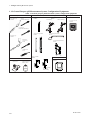

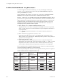
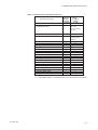

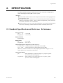
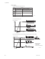
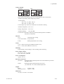


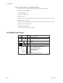
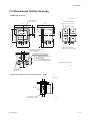
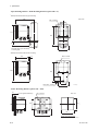
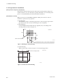
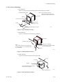
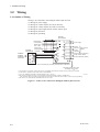

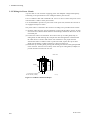
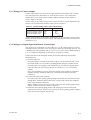
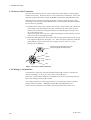
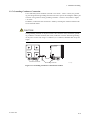

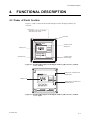


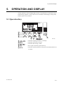
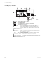
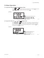
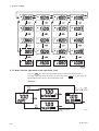
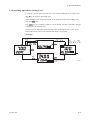

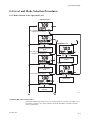

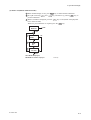
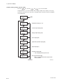
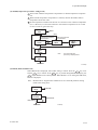


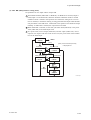

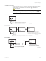

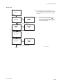

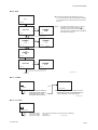
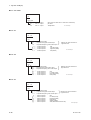
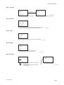

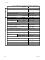


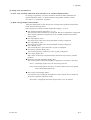

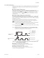
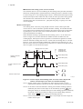


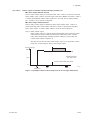
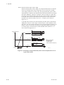

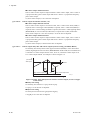
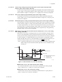

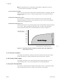
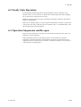


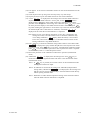

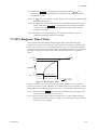
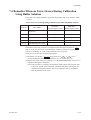


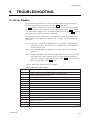
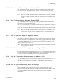
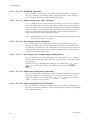
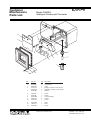
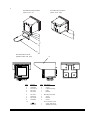

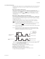


![Model DO402G Dissolved Oxygen Converter [Style: S3]](http://vs1.manualzilla.com/store/data/005725233_1-bd7e4c5bf258da59a958f30153ff00ea-150x150.png)


![Model ISC450G [Style: S2] Inductive Conductivity](http://vs1.manualzilla.com/store/data/005904832_1-e9e6bdf8409b6fd37a184b6e2701b530-150x150.png)
![SS400G MLSS Converter [Style:S2.2]](http://vs1.manualzilla.com/store/data/005726371_1-b873ef07ceb169a0226d293b313a67fd-150x150.png)