1
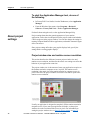
Performance and Visibility
FactoryTalk® View Machine Edition User's
Guide
User's Guide
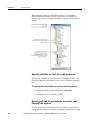
Table of contents
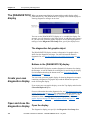
About the documentation .................................................................... 29
Find the information you need ............................................................ 29
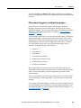
Try the User's Guide and Help first .............................................. 29
Find information on the Internet ................................................... 30
Contact Rockwell Automation Technical Support ....................... 30
Legal Notices ...................................................................................... 31
Preface
Chapter 1
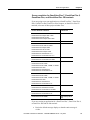
Review operating system requirements .............................................. 35
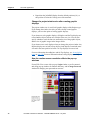
The parts of FactoryTalk View Machine Edition ............................... 36
Additional software ....................................................................... 36
The FactoryTalk View Machine Edition tools.................................... 36
FactoryTalk View Studio tools ..................................................... 36
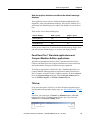
Diagnostics Viewer ....................................................................... 38
FactoryTalk tools .......................................................................... 38
FactoryTalk Activation Manager .................................................. 38
Get Started
Chapter 2
Explore FactoryTalk
View Studio
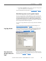
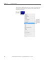
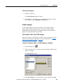
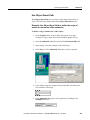
Start and exit FactoryTalk View Studio.............................................. 39
Start FactoryTalk View Studio ..................................................... 39
Exit FactoryTalk View Studio ...................................................... 39
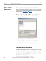
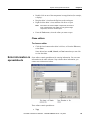
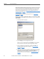
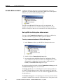
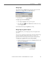
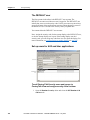
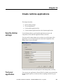
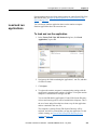
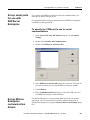
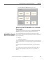
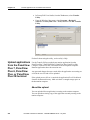
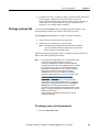
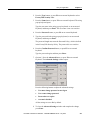
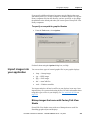
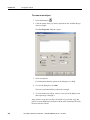
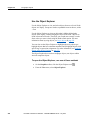
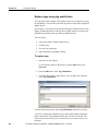
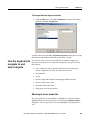
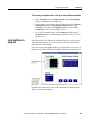
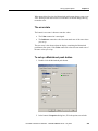
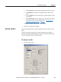
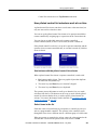
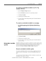
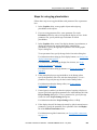
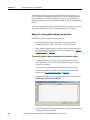
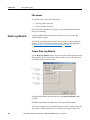
Open sample applications ................................................................... 40
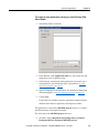
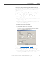
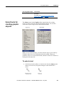
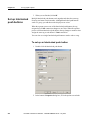
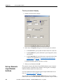
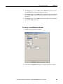
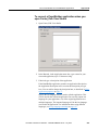
To open the InstantFizz_ME sample application.......................... 40
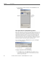
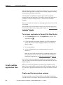
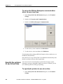
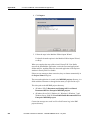
Problems opening applications ..................................................... 40
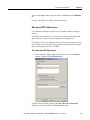
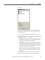
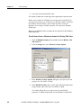
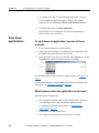
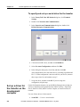
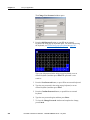
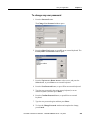
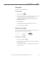
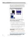
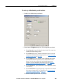
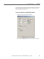
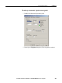
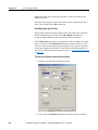
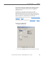
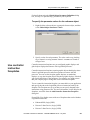
To set up write access for any Windows Security Group ............. 41
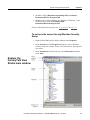
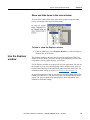
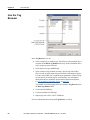
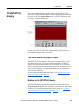
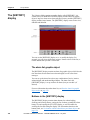
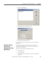
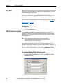
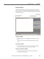
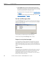
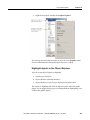
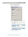
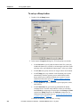
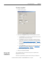
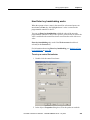
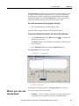
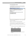
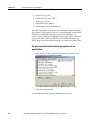
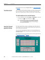
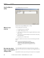
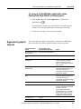
Explore the FactoryTalk View Studio main window ......................... 41
The menu bar ................................................................................ 42
The toolbar .................................................................................... 42
The Explorer window ................................................................... 42
The workspace .............................................................................. 42
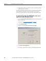
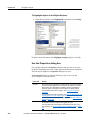
The Diagnostics List ..................................................................... 43
The status bar ................................................................................ 44
Workbook tabs .............................................................................. 44
Show and hide items in the main window .................................... 45
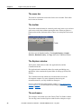
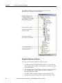
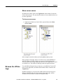
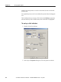
Use the Explorer window.................................................................... 45
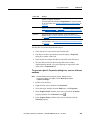
View the Explorer window ........................................................... 46
Move and resize the Explorer window ......................................... 47
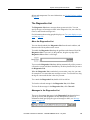
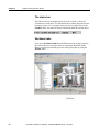
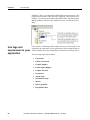
Work with editors ............................................................................... 47
Locate editors ................................................................................ 47
View an editor's components ........................................................ 48
Open editors .................................................................................. 48
Rockwell Automation Publication - VIEWME-UM004K-EN-E – July 2015
3
Table of contents
Close editors.................................................................................. 49
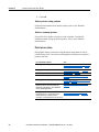
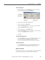
Enter information in spreadsheets ....................................................... 49
To enter information in a cell in a spreadsheet ............................. 50
To move to the next cell in the row .............................................. 50
To move to the first cell in the next row ....................................... 50
To delete a cell’s contents ............................................................. 50
To delete rows ............................................................................... 51
Print ..................................................................................................... 51
To print an editor’s contents ......................................................... 51
Select a printer .............................................................................. 51
Print at run time ............................................................................ 52
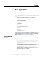
Chapter 3
Plan applications
Understand the process ....................................................................... 53
Collect data ......................................................................................... 54
Design an HMI tag database ............................................................... 54
Collect information ....................................................................... 54
Organize tags ................................................................................ 54
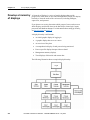
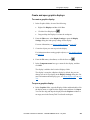
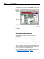
Plan graphic displays .......................................................................... 55
Develop a hierarchy of displays .................................................... 55
Create a template to ensure consistency ....................................... 56
Design displays ............................................................................. 56
Plan languages .................................................................................... 57
Plan alarms .......................................................................................... 58
Provide information for the operator .................................................. 58
Local and information messages ................................................... 58
Diagnostics messages.................................................................... 58
Plan trends ........................................................................................... 58
Plan recipes ......................................................................................... 59
Design a secure system ....................................................................... 59
Chapter 4
Work with
applications
4
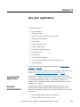
What is an application? ....................................................................... 61
Application versus project ............................................................ 61
HMI project file ............................................................................ 62
Runtime application file ................................................................ 62
Component files ............................................................................ 62
External folders ............................................................................. 63
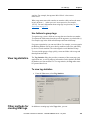
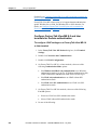
Default log file locations for PanelView Plus 7, PanelView Plus 6,
PanelView Plus, or PanelView Plus CE applications ................... 63
Name files ..................................................................................... 64
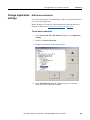
Creat, import, open, and close applications ........................................ 64
Creat applications.......................................................................... 64
Rockwell Automation Publication - VIEWME-UM004K-EN-E – July 2015
Table of contents
Import applications ....................................................................... 66
Open applications.......................................................................... 67
Open multiple applications ........................................................... 70
Open and edit applications from earlier versions of RSView or
FactoryTalk View ME .................................................................. 70
Close applications ......................................................................... 71
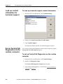
Rename, copy, delete, back up, and restore applications.................... 71
To start the Application Manager tool, do one of the following .. 72
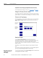
About project settings ......................................................................... 72
Project window size and runtime screen resolution ...................... 72
PanelView Plus 7 Standard applications and Compact Machine
Edition applications ...................................................................... 75
Title bar ......................................................................................... 75
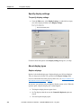
Specify project settings ....................................................................... 76
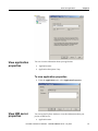
View application properties ................................................................ 77
To view application properties...................................................... 77
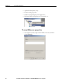
View HMI server properties ............................................................... 77
To view HMI server properties ..................................................... 78
Chapter 5
Set up
communications
About data servers............................................................................... 79
About OPC communications .............................................................. 79
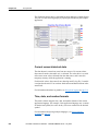
Create data servers .............................................................................. 80
Set up RSLinx Enterprise data servers.......................................... 80
Set up an OPC data server ............................................................ 81
Update data server caches ............................................................. 82
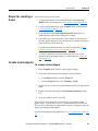
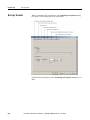
Steps for transferring applications to a PanelView Plus terminal....... 82
To set up communications .................................................................. 82
Chapter 6
Work with tags
Types of tags ....................................................................................... 85
Data server tags ............................................................................. 85
HMI tags ....................................................................................... 86
The data source ............................................................................. 86
Basic steps for using tags .............................................................. 86
When to use data server tags ............................................................... 87
Eliminate duplication .................................................................... 87
Use complex data .......................................................................... 87
Steps for using data server tags ........................................................... 87
When to use HMI tags ........................................................................ 88
Scale, offset, or provide a range for data ...................................... 88
Store values in FactoryTalk View memory .................................. 89
Steps for using HMI tags .................................................................... 89
Rockwell Automation Publication - VIEWME-UM004K-EN-E – July 2015
5
Table of contents
Browse for tags ................................................................................... 89
To open the Tag Browser .............................................................. 89
Use the Tag Browser ........................................................................... 90
Show server names ....................................................................... 91
Browse for off-line tags ...................................................................... 91
Use tags and expressions in your application ..................................... 92
Assign tags .................................................................................... 93
Assign tags to graphic objects....................................................... 93
Use expressions to manipulate tag values ..................................... 94
Substitute tag names used in graphic objects ................................ 95
Log tag values ..................................................................................... 95
Use macros to assign values to tags .................................................... 95
Chapter 7
Use HMI tags
6
HMI tag types ..................................................................................... 97
Analog tags that use floating-point values .................................... 98
How values are rounded................................................................ 98
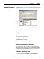
Use the Tags editor ............................................................................. 99
Update the contents of the Tags editor ......................................... 99
Search for HMI tags .................................................................... 100
Data sources ...................................................................................... 102
The data source ........................................................................... 102
Device ......................................................................................... 102
Memory ....................................................................................... 102
Address syntax for device tags ......................................................... 103
Example: Logix5000 addressing................................................. 103
Organize HMI tags ............................................................................ 104
Name tags.................................................................................... 104
Use folders to group tags ............................................................ 105
View tag statistics ............................................................................. 105
To view tag statistics ................................................................... 105
Other methods for creating HMI tags ............................................... 105
Create tags as needed in other FactoryTalk View editors........... 106
Create tags as needed in the Data Log Models editor ................. 106
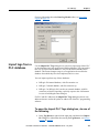
Import tags from a PLC database...................................................... 107
To open the Import PLC Tags dialog box, do one of the following
..................................................................................................... 107
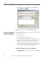
Use the Tag Import and Export Wizard ............................................ 108
To start the wizard, do one of the following ............................... 108
Rockwell Automation Publication - VIEWME-UM004K-EN-E – July 2015
Table of contents
Chapter 8
Set up global
connections
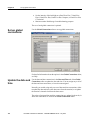
About global connections ................................................................. 111
Set up global connections ................................................................. 112
Update the date and time................................................................... 112
Update the date and time at the data source from the terminal ... 113
Update the date and time at the terminal from the data source ... 113
Change displays ................................................................................ 114
Control display changes remotely............................................... 114
Remote display changes and security ......................................... 114
Set up remote display changes .................................................... 114
Print displays ..................................................................................... 115
Close On Top displays ...................................................................... 116
Apply parameters to changed displays ............................................. 116
Run macros ....................................................................................... 116
Set up backlight intensity remotely .................................................. 117
Monitor runtime RAM usage ............................................................ 117
Chapter 9
Set up alarms
About alarms ..................................................................................... 119
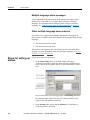
Multiple language alarm messages ............................................. 120
Other multiple language alarm features ...................................... 120
Steps for setting up alarms ................................................................ 120
Prepare to set up alarms .................................................................... 121
The data source ........................................................................... 121
Tags and expressions .................................................................. 121
Identify alarm conditions ............................................................ 122
Import and export alarm setup files ............................................ 122
How alarms work .............................................................................. 122
Alarm triggers and trigger values ............................................... 122
Filter alarm triggers in multiple languages ................................. 123
Alarm notification methods ........................................................ 124
Show alarm information ............................................................. 124
Interact with alarms..................................................................... 125
The alarm log file ........................................................................ 129
Alarm trigger data types.................................................................... 129
The Value trigger type ................................................................ 129
The Bit trigger type ..................................................................... 130
The Least Significant Bit (LSBit) trigger type ........................... 132
Tips for using array tags ................................................................... 133
Equivalent data types .................................................................. 134
RSLinx Enterprise tag syntax ..................................................... 134
KEPServer Enterprise tag syntax ................................................ 135
Create alarm messages in multiple languages .................................. 135
Rockwell Automation Publication - VIEWME-UM004K-EN-E – July 2015
7
Table of contents
Language switching alarm messages in FactoryTalk View ME
Station 4.00 ................................................................................. 135
Optional alarm connections .............................................................. 135
Connections that work with a specific alarm trigger ........................ 136
How the Handshake connection works ....................................... 136
How the Ack connection works .................................................. 137
How the Remote Ack connection works .................................... 137
How the Remote Ack Handshake connection works .................. 139
Ensure alarm messages are read by the data source before sending new
messages ........................................................................................... 139
Methods of alarm message handshaking .................................... 139
Hold the message for a specific period of time........................... 140
Hold the message until the data source acknowledges that it has
read the message ......................................................................... 140
How messages are queued .......................................................... 141
How the Message connection works........................................... 141
How the Message Notification connection works ...................... 141
How the Message Handshake connection works ........................ 142
Connections that apply to all alarms ................................................. 142
How the Silence connection works ............................................. 142
How the Remote Silence connection works ............................... 143
How the Remote Ack All connection works .............................. 143
How the Status Reset connection works ..................................... 143
How the Remote Status Reset connection works ....................... 143
How the Close Display connection works .................................. 144
How the Remote Close Display connection works..................... 144
The [ALARM] display...................................................................... 144
The alarm banner graphic object................................................. 145
Buttons in the [ALARM] display ............................................... 145
The [ALARM BANNER] display .................................................... 145
The alarm banner graphic object................................................. 145
Buttons in the [ALARM BANNER] display .............................. 145
The [ALARM MULTI-LINE] display.............................................. 146
The alarm list graphic object....................................................... 146
Buttons in the [ALARM MULTI-LINE] display ....................... 146
The [STATUS] display ..................................................................... 147
The alarm status list graphic object ............................................ 147
Buttons in the [STATUS] display ............................................... 147
The [HISTORY] display ................................................................... 148
The alarm list graphic object....................................................... 148
Buttons in the [HISTORY] display............................................. 148
Use displays from the library in your application ............................. 149
Create your own alarm display ......................................................... 149
Open and close the alarm display ..................................................... 149
Open the display ......................................................................... 149
Close the display ......................................................................... 150
8
Rockwell Automation Publication - VIEWME-UM004K-EN-E – July 2015
Table of contents
How the alarm list graphic object works .......................................... 150
What is shown ............................................................................. 151
How the list scrolls...................................................................... 152
How the alarm banner graphic object works .................................... 152
What is shown ............................................................................. 152
How the alarm status list graphic object works ................................ 153
What is shown ............................................................................. 153
What happens when the display is opened ................................. 154
Use buttons with the alarm history and alarm objects ...................... 154
Alarm buttons.............................................................................. 154
Link alarm buttons to objects ...................................................... 155
Key buttons ................................................................................. 156
Use alarm buttons to acknowledge, silence, clear, and delete alarms
........................................................................................................... 156
Acknowledge the selected alarm ................................................ 156
Acknowledge all alarms .............................................................. 157
Silence alarms ............................................................................. 158
Clear and delete messages .......................................................... 158
Use alarm buttons to sort alarms and reset alarm status ................... 158
Sort alarms .................................................................................. 158
Reset alarm status ....................................................................... 158
Retain alarm status ...................................................................... 159
Change the alarm status shown in the alarm status list ............... 159
Chapter 10
Set up FactoryTalk
Diagnostics
About FactoryTalk Diagnostics ........................................................ 161
Browse diagnostics messages ..................................................... 161
How to set up FactoryTalk Diagnostics ...................................... 162
Destinations................................................................................. 162
Message routing .......................................................................... 163
Categories ................................................................................... 164
Message severities ...................................................................... 164
Audiences .................................................................................... 165
Show diagnostics messages during application development .......... 165
To show the Diagnostics List ...................................................... 165
If you don’t want to show diagnostics messages ........................ 165
View FactoryTalk Diagnostics log files ........................................... 166
To open the FactoryTalk Diagnostics Viewer, do one of the
following ..................................................................................... 166
Use the Diagnostics Setup tool ......................................................... 166
To open the FactoryTalk Diagnostics Setup tool, do one of the
following ..................................................................................... 166
Log to an ODBC database .......................................................... 167
Route messages ........................................................................... 168
Rockwell Automation Publication - VIEWME-UM004K-EN-E – July 2015
9
Table of contents
Receive messages from a PanelView Plus 7, PanelView Plus 6,
PanelView Plus, or PanelView Plus CE terminal ....................... 168
Show and print diagnostics messages at run time............................. 169
Use the Diagnostics List Setup editor ......................................... 169
Set up how messages are shown and printed at run time ............ 171
The [DIAGNOSTICS] display ......................................................... 172
The diagnostics list graphic object .............................................. 172
Buttons in the [DIAGNOSTICS] display ................................... 172
Create your own diagnostics display ................................................ 172
Open and close the diagnostics display ............................................ 172
Open the display ......................................................................... 172
Close the display ......................................................................... 173
How the diagnostics list graphic object works ................................. 173
What is shown ............................................................................. 173
Use buttons with the diagnostics list........................................... 173
Chapter 11
Set up security
10
Use security with your application ................................................... 175
If you do not create additional FactoryTalk View user accounts 176
If you use FactoryTalk View user accounts ................................ 176
Steps for setting up security .............................................................. 177
Create FactoryTalk Security users .............................................. 177
Create FactoryTalk Security user groups .................................... 178
Work with the Runtime Security editor ............................................ 179
How user accounts and security codes work .................................... 179
The DEFAULT user ................................................................... 180
Set up users for 4.00 and later applications ................................ 180
To remove a FactoryTalk Security user or group from FactoryTalk
View ............................................................................................ 182
To migrate RSView 3.20 and earlier users to FactoryTalk View182
Set up users for 3.20 and earlier applications ............................. 183
Change RSView 3.20 and earlier user passwords ...................... 183
Add 3.20 and earlier users or groups from a Windows domain . 183
Remove 3.20 and earlier users or groups .................................... 185
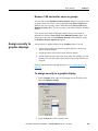
Assign security to graphic displays................................................... 185
To assign security to a graphic display ....................................... 185
Provide a way for users to log in and log out ................................... 186
Log in .......................................................................................... 186
Log out ........................................................................................ 186
Log out automatically ................................................................. 187
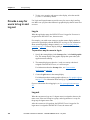
Application examples........................................................................ 187
Example: Assign security codes to prevent access to graphic
displays ....................................................................................... 187
Example: Use security codes to control the visibility of the
shutdown button .......................................................................... 188
Rockwell Automation Publication - VIEWME-UM004K-EN-E – July 2015
Table of contents
Example 3: Assign visibility animation to the Goto display button
..................................................................................................... 189
Example 4: Assign visibility animation to the shutdown button 190
Example 5: Assign visibility animation to the shutdown button 190
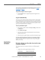
Example 6: Prevent unauthorized users from stopping the
application ................................................................................... 190
Set up FactoryTalk Security for your application ............................. 191
Specify activities to track for audit purposes .............................. 192
Specify policies for passwords, accounts, and FactoryTalk sign-on
..................................................................................................... 192
Uncommon security permissions ................................................ 193
Set up security access to the FactoryTalk Directory ................... 193
Set up security access to the application ..................................... 194
Set up security access to System policies, groups, and users ..... 194
Set up security access to networks and devices .......................... 194
Chapter 12
Set up language
switching
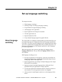
About language switching................................................................. 197
The default language ................................................................... 198
Steps for setting up language switching............................................ 199
Set up Windows for language switching .......................................... 200
Install Windows languages ......................................................... 200
Set up Windows fonts ................................................................. 200
Windows locale settings ............................................................. 201
Add languages to the application ...................................................... 201
To add languages to an application ............................................. 201
Remove languages ...................................................................... 201
Export application text strings for translation ................................... 202
Export text in Unicode format .................................................... 202
Export text to a Microsoft Excel spreadsheet ............................. 203
Excel spreadsheet file name format ............................................ 203
Exported language string file locations....................................... 204
Problems exporting ..................................................................... 204
Translate application text in Excel spreadsheet files ........................ 205
Translate application text in Unicode files ....................................... 205
File name and format .................................................................. 205
Open the text file in Microsoft Excel .......................................... 206
Save the text file in Microsoft Excel........................................... 206
Differences in file format for files saved in Excel ...................... 207
Save the Unicode text file in Notepad ........................................ 207
File schema ................................................................................. 207
Work with pairs of double quotes ............................................... 208
Work with backslashes and new line characters ......................... 209
Import text ......................................................................................... 209
To import text into your application from a text file .................. 210
Rockwell Automation Publication - VIEWME-UM004K-EN-E – July 2015
11
Table of contents
Problems importing........................................................................... 210
Cancel importing ......................................................................... 210
Set up multiple language support for graphic libraries ..................... 211
To turn on support for multiple languages in a graphic library .. 211
Use graphic libraries that support multiple languages ................ 211
Chapter 13
About display navigation .................................................................. 213
Develop a hierarchy of displays ........................................................ 214
Test display navigation ..................................................................... 215
Use graphic objects to navigate ........................................................ 215
Switch languages ........................................................................ 215
Display type ................................................................................ 216
Goto display buttons ................................................................... 216
Goto configure mode buttons...................................................... 216
Return to display buttons ............................................................ 217
Close display buttons .................................................................. 218
Display list selectors ................................................................... 218
Shutdown buttons........................................................................ 219
Control display changes remotely..................................................... 220
Set up display
navigation
Chapter 14
Specify startup settings ..................................................................... 221
Test your application......................................................................... 221
To test your application in FactoryTalk View Studio ................. 222
Create runtime application files ........................................................ 222
Create .mer files for previous versions ....................................... 222
Convert .mer files to development applications ......................... 223
Convert runtime application files to development applications ....... 226
To convert a runtime application to a development application . 226
Create runtime
applications
Chapter 15
Run applications on
a personal computer
12
Steps for transferring applications to a PanelView Plus terminal..... 229
Install hardware and software on the runtime computer ............. 230
Transfer the application .............................................................. 231
Set up options in FactoryTalk View ME Station ........................ 231
Move applications to the runtime computer ..................................... 232
Start FactoryTalk View ME Station ................................................. 232
To start FactoryTalk View ME Station....................................... 232
Load and run applications ................................................................. 233
To load and run the application .................................................. 233
Shut down applications ..................................................................... 234
Rockwell Automation Publication - VIEWME-UM004K-EN-E – July 2015
Table of contents
To shut down an application, use one of these methods ............. 234
What happens when the application shuts down ........................ 234
Change application settings .............................................................. 235
Edit device shortcuts ................................................................... 235
Look up contact information for technical support........................... 236
To look up technical support contact information ...................... 236
Set up FactoryTalk Diagnostics on the runtime computer................ 236
To set up FactoryTalk Diagnostics on the runtime computer ..... 236
Set up serial ports for use with KEPServer Enterprise ..................... 237
To specify the COM port to use for serial communications ....... 237
Set up RSLinx Enterprise communication drivers............................ 237
To set up the RSLinx Enterprise communication driver to use at
run time ....................................................................................... 238
Specify the printers to use at run time .............................................. 238
To specify the printers to use at run time .................................... 238
Specify startup options for FactoryTalk View ME Station .............. 239
To start FactoryTalk View ME Station and run an application
when Windows starts .................................................................. 240
To start FactoryTalk View ME Station without running an
application when Windows starts ............................................... 241
Use Windows Server 2012, Windows 8.1, Windows 8, Windows 7,
and Windows Server 2008 with ME Station............................... 243
Delete log files on the runtime computer.......................................... 243
Run a newer version of the application....................................... 243
Delete log files manually ............................................................ 244
Turn off the FactoryTalk Directory Server warning ......................... 244
To turn off the overwrite warning ............................................... 244
Specify time, date, and number formats ........................................... 244
Use the DeskLock tool ...................................................................... 245
To open the DeskLock tool ......................................................... 245
Chapter 16
Transfer applications
to a PanelView Plus
terminal
Steps for transferring applications to a PanelView Plus terminal..... 247
Install hardware and software on a PanelView Plus terminal..... 248
Install printers on a PanelView Plus terminal ............................. 248
Install hardware and software on a PanelView Plus 7 or PanelView
Plus 6 terminal ............................................................................ 249
Install printers on a PanelView Plus 7 or PanelView Plus 6
terminal ....................................................................................... 249
Transfer applications ................................................................... 250
Start FactoryTalk View ME Station ................................................. 250
To start FactoryTalk View ME Station on a PanelView Plus 7 or
PanelView Plus 6 terminal .......................................................... 250
Start FactoryTalk View ME Station on a PanelView Plus terminal
..................................................................................................... 251
Rockwell Automation Publication - VIEWME-UM004K-EN-E – July 2015
13
Table of contents
Specify the driver to use for the transfer ........................................... 251
To specify and set up a serial driver for the transfer................... 252
Set up a driver for the transfer on the development computer .......... 252
Download applications and Windows TrueType fonts ..................... 253
About the download .................................................................... 253
Serial downloads ......................................................................... 253
Upload applications from the PanelView Plus 7, PanelView Plus 6,
PanelView Plus, or PanelView Plus CE terminal ............................. 254
About the upload ......................................................................... 254
Serial uploads .............................................................................. 255
Compare applications........................................................................ 255
Chapter 17
Use your application
14
Log in to the application ................................................................... 257
Domain authentication ...................................................................... 257
Configure FactoryTalk View ME 8.0 and later terminals for
Domain authentication ................................................................ 258
Configure FactoryTalk View ME prior to 8.0 terminals for Domain
authentication .............................................................................. 262
Access network resources from a terminal ....................................... 263
To provide access to network resources when using a PanelView
Plus 7, PanelView Plus 6, PanelView Plus, or PanelView Plus CE
terminal ....................................................................................... 263
Log in to the application ................................................................... 263
4.00 and later applications .......................................................... 264
3.20 and earlier applications ....................................................... 264
What happens when a user logs in .............................................. 266
Problems with logging in ............................................................ 266
Change passwords ............................................................................. 267
To change your current password ............................................... 267
To change any user password ..................................................... 269
Log out .............................................................................................. 270
To log out .................................................................................... 270
Add a user or group........................................................................... 270
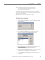
To add a FactoryTalk security user ............................................. 270
To add a Windows-linked user or group..................................... 272
Delete a user or group ....................................................................... 272
To delete a user or group ............................................................ 273
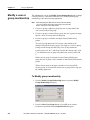
Modify a user or group membership ................................................. 274
To Modify group membership .................................................... 274
Unlock a user .................................................................................... 275
To unlock a user .......................................................................... 276
Disable a user .................................................................................... 276
To disable a user ......................................................................... 276
Enable a user ..................................................................................... 277
Rockwell Automation Publication - VIEWME-UM004K-EN-E – July 2015
Table of contents
To enable a user .......................................................................... 277
Change User Properties..................................................................... 277
To modify a user’s properties ..................................................... 277
Enter numeric values......................................................................... 278
Activate the cursor point ............................................................. 278
Ramp numeric values .................................................................. 279
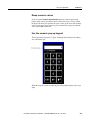
Use the numeric pop-up keypad ................................................. 279
Use the numeric pop-up scratchpad ............................................ 280
Use buttons and keys with the numeric pop-up windows........... 280
How values are ramped ............................................................... 281
How values are calculated .......................................................... 281
Problems with the numeric pop-up windows.............................. 282
Enter string values............................................................................. 282
Use the string pop-up keyboard .................................................. 283
Use the string pop-up character input ......................................... 283
Use the string pop-up scratchpad ................................................ 285
Use buttons and keys with the string pop-up windows............... 285
What is written to the Value connection ..................................... 286
Problems with the string pop-up windows.................................. 286
Change tag values ............................................................................. 287
View tag data .................................................................................... 289
Show the date and time ............................................................... 290
View alarms and messages ............................................................... 290
View information about runtime communication errors .................. 291
Change languages ............................................................................. 291
To change languages ................................................................... 291
Chapter 18
Work with
components
Editors that have components ........................................................... 293
To view a list of components for an editor ................................. 293
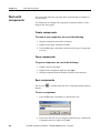
Work with components ..................................................................... 294
Create components ...................................................................... 294
Open components........................................................................ 294
Save components ........................................................................ 294
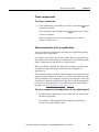
Close components ....................................................................... 295
Add components into an application........................................... 295
Delete components ...................................................................... 297
Remove components ................................................................... 297
Rename components ................................................................... 297
Duplicate components ................................................................. 298
Print components ........................................................................ 298
Rockwell Automation Publication - VIEWME-UM004K-EN-E – July 2015
15
Table of contents
Chapter 19
Use graphic displays
16
About graphic displays and graphic objects ..................................... 299
Before you begin ............................................................................... 300
Use the Graphics editor ..................................................................... 300
Create and open graphic displays ............................................... 301
Import and export graphic displays............................................. 302
Tools and tips for working in the Graphics editor ............................ 303
Use context menus ...................................................................... 303
Use the toolbars........................................................................... 305
Show displays in grayscale ......................................................... 306
Use the grid ................................................................................. 306
Zoom in and out .......................................................................... 307
Correct mistakes.......................................................................... 308
Test your displays as you work ................................................... 308
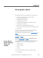
Set up graphic displays ..................................................................... 309
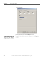
Specify display settings............................................................... 310
About display types..................................................................... 310
Resize displays ............................................................................ 311
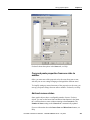
Create a background for your display ............................................... 312
To convert objects to wallpaper .................................................. 312
To unlock the wallpaper.............................................................. 313
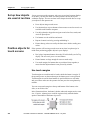
Use graphic libraries ......................................................................... 313
Work with Symbol Factory............................................................... 313
To open Symbol Factory............................................................. 313
To select a graphic: ..................................................................... 314
Manipulate the graphic: .............................................................. 314
Create graphic libraries ............................................................... 315
Use libraries as displays in your application............................... 316
Use libraries to store displays with multiple languages .............. 316
Location of library components .................................................. 318
Import images into your application ................................................. 319
Bitmap images that come with FactoryTalk View Studio .......... 319
Import bitmap, PNG, and JPEG images ..................................... 320
Use the Image Browser to import images ................................... 322
Use Symbol Factory.................................................................... 323
Tips for using images .................................................................. 324
Use local messages ........................................................................... 325
Local messages versus information messages ............................ 325
Steps for setting up local messages ............................................. 325
Use the Local Messages editor ................................................... 326
Prepare to set up local messages ................................................. 326
How local messages work ........................................................... 327
Local messages and trigger values .............................................. 328
Create local messages in multiple languages .............................. 329
How the local message display graphic object works ................ 329
Rockwell Automation Publication - VIEWME-UM004K-EN-E – July 2015
Table of contents
Print displays ..................................................................................... 329
Print displays at run time ............................................................ 330
Chapter 20
Use graphic objects
Types of graphic objects ................................................................... 331
Use the tables .............................................................................. 332
About connections ...................................................................... 332
Use graphic objects ........................................................................... 332
Illustrate your displays ................................................................ 332
Control the application ................................................................ 333
Start and control processes.......................................................... 335
Show processes and values graphically ...................................... 336
Work with lists, trends, alarm banners, and numeric input objects
..................................................................................................... 337
Enter and show numeric and string values ................................. 339
Show alarms and messages ......................................................... 340
Select tools for creating graphic objects ........................................... 341
To select a tool ............................................................................ 341
To deselect a tool, do one of the following ................................. 342
Before you begin creating objects..................................................... 342
To use the grid ............................................................................ 342
Create graphic objects ....................................................................... 342
To create a graphic object ........................................................... 342
Create drawing objects ...................................................................... 343
Create text ................................................................................... 343
Create images .............................................................................. 345
Create panels ............................................................................... 347
Create arcs and wedges ............................................................... 347
Create ellipses and circles ........................................................... 348
Create freehand shapes ............................................................... 349
Create lines.................................................................................. 349
Create polygons and polylines .................................................... 350
Create rectangles and squares ..................................................... 351
Create rounded rectangles and squares ....................................... 351
Use .wmf and .dxf files ............................................................... 352
Use ActiveX objects ................................................................... 353
Tools and tips for working with objects ........................................... 354
Select and deselect objects .......................................................... 355
Use the Object Explorer .............................................................. 356
Highlight objects in the Object Explorer .................................... 357
Use the Properties dialog box ..................................................... 358
Use the Property Panel ................................................................ 360
Set up properties ......................................................................... 361
Assign tags and expressions to an object’s connections ............. 361
Color objects using the color toolbars ........................................ 362
Rockwell Automation Publication - VIEWME-UM004K-EN-E – July 2015
17
Table of contents
Name objects ............................................................................... 364
Test how objects look in different states..................................... 365
Assign tags and expressions to graphic objects ................................ 366
Assign tags .................................................................................. 366
Use expressions to manipulate tag values ................................... 367
Replace tags using tag substitution ............................................. 368
Replace tags using Find and Replace.......................................... 369
Use tag placeholders ................................................................... 370
Perform basic operations on objects ................................................. 371
Move objects ............................................................................... 371
Copy objects................................................................................ 372
Duplicate objects ......................................................................... 374
Resize objects.............................................................................. 375
Reshape drawing objects............................................................. 377
Delete objects .............................................................................. 378
Work with groups of objects ............................................................. 378
Group and ungroup objects ......................................................... 378
Edit groups of objects ................................................................. 379
Edit objects within a group ......................................................... 380
Arrange objects ................................................................................. 381
Layer objects ............................................................................... 381
Align objects ............................................................................... 382
Space objects ............................................................................... 384
Flip drawing objects .................................................................... 385
Rotate drawing objects ................................................................ 386
Lock objects into position ........................................................... 387
Chapter 21
Set up graphic
objects
18
Set up objects’ spatial properties, names, and visibility ................... 389
Tips for setting up objects with states ............................................... 390
Copy and paste properties from one state to another .................. 391
Add and remove states ................................................................ 391
Set up how objects are used at run time ............................................ 392
Position objects for touch screens ..................................................... 392
Use touch margins....................................................................... 392
Assign function keys to buttons ........................................................ 393
Function key equivalents ............................................................ 394
Use the keyboard to navigate to and select objects........................... 395
What input focus looks like ........................................................ 395
Use the keys on the keyboard or keypad .................................... 396
Remove objects from and adding objects to the tab sequence.... 396
Link buttons to objects ...................................................................... 397
To link a button to a specific object using the button’s Properties
dialog box.................................................................................... 398
To link a button to a specific object using the Property Panel ... 398
Rockwell Automation Publication - VIEWME-UM004K-EN-E – July 2015
Table of contents
Repeat a button’s action by holding down the button....................... 399
To set up auto repeat for a button, use one of these methods ..... 399
Ensure values are read by the data source before sending new values
........................................................................................................... 400
Methods of Enter key handshaking............................................. 400
Hold the value for a specific period of time ............................... 400
Hold the value until it is acknowledged ...................................... 401
Time, date, and number formats for graphic objects ........................ 403
Set up buttons.................................................................................... 403
To set up a button ........................................................................ 405
Buttons described later in the chapter ......................................... 406
How to use push buttons ................................................................... 406
Set up Momentary push buttons ....................................................... 407
The error state ............................................................................. 407
To set up a Momentary push button ........................................... 408
Set up Maintained push buttons ........................................................ 408
The error state ............................................................................. 409
To set up a Maintained push button ............................................ 409
Set up Latched push buttons ............................................................. 410
The error state ............................................................................. 410
To set up a Latched push button ................................................. 411
Set up Multistate push buttons .......................................................... 412
The error state ............................................................................. 412
To set up a Multistate push button .............................................. 413
Set up Interlocked push buttons ........................................................ 414
To set up an Interlocked push button .......................................... 414
Set up Ramp buttons ......................................................................... 415
To set up a Ramp button ............................................................. 416
Set up numeric displays .................................................................... 417
How values are shown ................................................................ 417
Problems with showing values ................................................... 417
Set up Numeric Input Enable buttons ............................................... 418
To set up a Numeric Input Enable button ................................... 419
Set up numeric input cursor points ................................................... 420
To set up a numeric input cursor point ....................................... 421
Set up string displays ........................................................................ 422
How values are shown ................................................................ 422
Set up String Input Enable buttons ................................................... 423
To set up a String Input Enable button ..................................... 424
Set up Goto display buttons .............................................................. 425
To set up a Goto display button .................................................. 425
Set up close display buttons .............................................................. 426
To set up a Close Display button ................................................ 426
Set up display list selectors ............................................................... 427
To set up a display list selector ................................................... 427
How to use indicators........................................................................ 428
Rockwell Automation Publication - VIEWME-UM004K-EN-E – July 2015
19
Table of contents
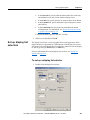
Set up multistate indicators ............................................................... 428
The error state ............................................................................. 428
To set up a multistate indicator ................................................... 429
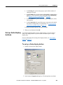
Set up symbols .................................................................................. 430
The error state ............................................................................. 430
To set up a symbol ...................................................................... 431
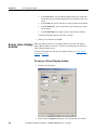
Set up list indicators .......................................................................... 431
To set up a list indicator .............................................................. 432
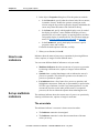
How to use bar graphs, gauges, and scales ....................................... 433
Bar graphs make it easy to compare values ................................ 433
Thresholds change a bar graph’s fill color .................................. 433
Use bar graphs with scales to show limits .................................. 434
Gauges make it easy to see limits ............................................... 434
Thresholds change a gauge’s fill color ....................................... 434
Set up bar graphs ............................................................................... 435
To set up a bar graph ................................................................... 435
Set up gauges .................................................................................... 436
To set up a gauge ........................................................................ 436
Set up scales ...................................................................................... 437
To set up a scale .......................................................................... 437
Set up control list selectors ............................................................... 438
Use buttons with the control list selector .................................... 438
How Enter key handshaking works ............................................ 439
Set up piloted control list selectors ................................................... 440
Choose between piloted control list selectors and control list
selectors....................................................................................... 440
How piloted control list selectors work at run time .................... 441
Set up local message displays ........................................................... 443
To set up a local message display ............................................... 444
Set up Macro buttons ........................................................................ 444
To set up a Macro button ............................................................ 445
Set up time and date displays ............................................................ 445
To set up a time and date display ................................................ 446
Set up Print Alarm History buttons ................................................... 446
To set up a Print Alarm History button ....................................... 447
Set up Print Alarm Status buttons ..................................................... 447
To set up a Print Alarm Status button ......................................... 448
Set up alarm lists ............................................................................... 448
To set up an alarm list ................................................................. 449
Set up alarm banners ......................................................................... 450
To set up an alarm banner ........................................................... 451
Set up alarm status lists ..................................................................... 451
To set up an alarm status list ....................................................... 452
Set up diagnostics lists ...................................................................... 453
To set up a diagnostics list .......................................................... 454
Set up information message displays ................................................ 454
20
Rockwell Automation Publication - VIEWME-UM004K-EN-E – July 2015
Table of contents
To set up an information message display .................................. 455
Chapter 22
Animate graphic
objects
Types of animation ........................................................................... 457
Which objects can have which types of animation? ................... 458
Use the Animation dialog box .......................................................... 458
To open the Animation dialog box, do one of the following ...... 458
About the Animation dialog box................................................. 460
Use Object Smart Path to visually set animation ........................ 460
Test animation ................................................................................... 460
To switch between test and edit modes....................................... 460
Use tag names and tag placeholders ................................................. 461
To create a tag placeholder ......................................................... 461
Use expressions ................................................................................. 461
Set minimum and maximum values .................................................. 462
Define a range of motion .................................................................. 462
Animation that does not use a range of motion .......................... 462
Use Object Smart Path ................................................................ 463
Set up the different types of animation ............................................. 464
Set up visibility animation .......................................................... 464
Set up color animation ................................................................ 465
Set up fill animation .................................................................... 468
Set up horizontal position animation .......................................... 469
Set up vertical position animation............................................... 469
Set up width animation ............................................................... 469
Set up height animation .............................................................. 470
Set up rotation animation ............................................................ 470
Set up horizontal slider animation .............................................. 470
Set up vertical slider animation................................................... 471
Apply animation to groups................................................................ 471
Check the animation on objects ........................................................ 472
To view the animation on an object using the Animation menu 472
To view the animation on an object using the Animation dialog
box............................................................................................... 472
Copy or duplicate objects with animation ........................................ 473
Copy animation without copying objects ......................................... 473
To copy and paste animation ...................................................... 473
Set up animation for global objects .................................................. 474
To set up animation for a reference object.................................. 474
Chapter 23
Use expressions
About expressions ............................................................................. 475
Expressions that result in floating-point values .......................... 475
Rockwell Automation Publication - VIEWME-UM004K-EN-E – July 2015
21
Table of contents
Expression components .............................................................. 476
Use the Expression editor ................................................................. 476
Use the Expression editor versus typing expressions directly .... 476
Where you can use expressions ........................................................ 477
Format expressions ........................................................................... 478
Use tag names and tag placeholders ................................................. 478
Use tag placeholders instead of tag names ................................. 479
Constants ........................................................................................... 479
Arithmetic operators ......................................................................... 480
String operands ........................................................................... 480
Relational operators .......................................................................... 481
How string operands are evaluated ............................................. 481
Logical operators .............................................................................. 481
Bitwise operators .............................................................................. 482
Use the left shift operator ............................................................ 483
Evaluation order of operators............................................................ 484
Mathematical functions ..................................................................... 485
Security functions ............................................................................. 486
Language function ............................................................................ 487
Language switching alarm, information, and local messages in
FactoryTalk View ME Station 4.00 ............................................ 487
If-then-else ........................................................................................ 488
Nested if-then-else ...................................................................... 489
Use write expressions ....................................................................... 490
To set up the Maintained push button ......................................... 491
To set up the Numeric Input Enable button ................................ 491
Chapter 24
Use embedded
variables
22
About embedded variables ................................................................ 493
Where you can create embedded variables ....................................... 494
Create embedded variables ............................................................... 494
To create an embedded variable in a graphic object’s caption ... 494
To create an embedded variable in an On Top display’s title bar
..................................................................................................... 495
To create an embedded variable in a message ............................ 495
Embedded variable syntax ................................................................ 495
Numeric embedded variable syntax ............................................ 495
String embedded variable syntax ................................................ 496
Time and date embedded variable syntax ................................... 497
How embedded variables are updated at run time ............................ 498
How embedded variables are shown at run time .............................. 499
Numeric embedded variables ...................................................... 499
String embedded variables .......................................................... 500
Time and date embedded variables ............................................. 500
Rockwell Automation Publication - VIEWME-UM004K-EN-E – July 2015
Table of contents
Chapter 25
Use parameters and
global objects
Use tag placeholders ......................................................................... 501
Steps for using tag placeholders ................................................. 503
Create parameter files ................................................................. 504
Use the Parameters editor ........................................................... 505
Use global objects ............................................................................. 509
Steps for setting up global objects .............................................. 510
Create global object displays and base objects ........................... 510
Create reference objects .............................................................. 511
Set up reference objects’ link properties ..................................... 513
Delete the base object ................................................................. 514
Use global object parameters ............................................................ 514
Difference between global object parameters and regular
parameters ................................................................................... 515
Use global object parameters with group objects ....................... 515
Steps for using global object parameters .................................... 516
Use controller instruction faceplates ................................................. 517
To add controllerinstruction faceplates to an application ........... 518
Chapter 26
Set up data logging
Steps for setting up data logging ....................................................... 519
Data log files ..................................................................................... 519
File names ................................................................................... 520
Data Log Models............................................................................... 520
Create Data Log Models ............................................................. 520
Data storage locations ................................................................. 521
Data logging methods ................................................................. 521
Tags in the data log model .......................................................... 522
Change the data log model used at run time ..................................... 522
To run a different data log model ............................................... 522
Show data logs using the trend graphic object.................................. 523
Problems with data logging .............................................................. 523
Chapter 27
Use information
messages
About information messages............................................................. 525
Information messages versus local messages ............................. 525
Steps for setting up information messages........................................ 525
Use the Information Messages editor ............................................... 526
Set up how information messages are shown ................................... 526
Prepare to set up information messages ............................................ 527
The data source ........................................................................... 527
Identify the tags and values to monitor ....................................... 527
Rockwell Automation Publication - VIEWME-UM004K-EN-E – July 2015
23
Table of contents
How information messages work...................................................... 527
Information messages and trigger values .................................... 529
Create information messages in multiple languages ......................... 529
Language switching information messages in FactoryTalk View
ME Station 4.00 .......................................................................... 529
The [INFORMATION] display ........................................................ 530
The information message display graphic object........................ 530
Buttons in the [INFORMATION] display .................................. 530
Use the information acknowledge button ................................... 531
Create your own information message display ................................. 531
Open and close the information message display ............................. 531
Open the display ......................................................................... 531
Close the display ......................................................................... 531
How the information message display graphic object works ........... 532
What is shown ............................................................................. 532
Change the message file used at run time ......................................... 532
Chapter 28
Set up trends
24
About trends ...................................................................................... 535
Current versus historical data...................................................... 536
Time, date, and number formats ................................................. 536
Steps for creating a trend .................................................................. 537
Create trend objects........................................................................... 537
To create a trend object ............................................................... 537
Set up trends ...................................................................................... 538
The parts of a trend ........................................................................... 539
Trend border................................................................................ 539
Trend window ............................................................................. 539
Chart ............................................................................................ 539
Y-axis .......................................................................................... 540
Vertical axis labels ...................................................................... 540
X-axis .......................................................................................... 540
Horizontal axis labels.................................................................. 540
Pens ............................................................................................. 540
Pen icons ..................................................................................... 541
Pen markers ................................................................................. 541
Chart types ........................................................................................ 541
Standard versus XY Plots ........................................................... 541
Isolated graphing ......................................................................... 542
Plot a value across the full width of the chart ............................. 542
Choose trend colors, fonts, lines, and markers ................................. 543
The trend border color ................................................................ 543
The trend window color .............................................................. 543
Test the trend..................................................................................... 544
To switch between test and edit modes....................................... 544
Rockwell Automation Publication - VIEWME-UM004K-EN-E – July 2015
Table of contents
Use the Trends graphic library.......................................................... 544
To use the Trends graphic library ............................................... 545
Use buttons to control the trend at run time ...................................... 545
Print trend data .................................................................................. 546
Improve clarity of the trend printout ........................................... 546
Runtime errors for the trend .............................................................. 546
Chapter 29
Set up RecipePlus
About recipes .................................................................................... 547
Steps for creating a recipe system ..................................................... 548
How the recipe system works ........................................................... 548
RecipePlus selector ..................................................................... 548
RecipePlus table .......................................................................... 548
RecipePlus button ....................................................................... 549
Number format ............................................................................ 550
Numeric limits ............................................................................ 550
Specify the runtime file location ....................................................... 550
Store files outside the HMI project ............................................. 551
Store recipe files with the HMI project....................................... 552
Set up recipe files .............................................................................. 552
Compare recipes................................................................................ 553
To compare recipes ..................................................................... 553
Time and date formats ................................................................ 555
Print recipes ...................................................................................... 555
Create RecipePlus objects ................................................................. 555
To create a recipe object ............................................................. 555
Test RecipePlus objects .................................................................... 556
To switch between test and edit modes....................................... 556
Use the RecipePlus_Components graphic library............................. 556
To use the RecipePlus_Components graphic library .................. 557
Use buttons with recipe objects ........................................................ 557
Example: Edit and downloading recipe values at run time......... 557
View data values that are saved at run time ...................................... 558
To view data values in modified recipe files .............................. 559
Chapter 30
Use macros
Use macros to assign values to tags .................................................. 561
Examples: Use macros to set tag values ..................................... 561
Use the Macros editor ....................................................................... 562
When to use macros .......................................................................... 562
Run macros when tags or expressions change value ........................ 562
Example: Use macros to reset tag values .................................... 563
Where to assign macros .................................................................... 563
Rockwell Automation Publication - VIEWME-UM004K-EN-E – July 2015
25
Table of contents
Appendix A
Convert PanelBuilder
1400e applications
Terminology...................................................................................... 565
Steps for converting PanelBuilder 1400e applications ..................... 566
Convert PanelBuilder 1400e application files .................................. 567
Steps to take in PanelBuilder 1400e before you convert the
application ................................................................................... 567
To convert a PanelBuilder 1400e application when you open
FactoryTalk View Studio ............................................................ 567
To convert a PanelBuilder 1400e application when FactoryTalk
View Studio is already open ....................................................... 569
Equivalent graphic objects ................................................................ 569
Unsupported graphic objects............................................................. 571
Unsupported settings and controls .................................................... 571
Controls for transferring runtime application files ..................... 571
Settings and controls for alarms .................................................. 572
Invalid characters in screen names ............................................. 572
Screen security settings ............................................................... 572
Block tags.................................................................................... 573
Convert non-RIO communications ................................................... 573
Unsupported tag data types ......................................................... 573
Unsupported initial values .......................................................... 574
Convert RIO communications .......................................................... 574
To convert an RIO application from PanelBuilder 1400e to
FactoryTalk View ....................................................................... 574
Unsupported PanelBuilder 1400e RIO tags ...................................... 575
Unsupported graphic object features ................................................ 576
Convert expressions .......................................................................... 578
To turn on an expression ............................................................. 578
Equivalent expression syntax ...................................................... 578
Unsupported expression syntax .................................................. 579
Order of precedence .................................................................... 580
Appendix B
Convert PanelBuilder
and PanelBuilder32
applications
26
Terminology...................................................................................... 581
Steps for converting PanelBuilder applications ................................ 582
Convert PanelBuilder application files ............................................. 582
Steps to take in PanelBuilder before you convert the application
..................................................................................................... 582
To convert a PanelBuilder application when you open FactoryTalk
View Studio ................................................................................ 583
To convert a PanelBuilder application when FactoryTalk View
Studio is already open ................................................................. 585
Equivalent graphic objects ................................................................ 585
Unsupported graphic objects............................................................. 586
Rockwell Automation Publication - VIEWME-UM004K-EN-E – July 2015
Table of contents
Unsupported settings and controls .................................................... 586
Settings and controls for alarms .................................................. 586
Invalid characters in screen names and tag names...................... 587
Time and date .............................................................................. 587
External fonts .............................................................................. 587
Screen security settings ............................................................... 587
Power-up options ........................................................................ 587
Convert non-RIO communications ................................................... 587
Tags for unsupported communication protocols......................... 588
Bit array tags ............................................................................... 588
Convert RIO communications .......................................................... 588
To convert an RIO application from PanelBuilder to FactoryTalk
View ............................................................................................ 589
Unsupported PanelBuilder RIO tags ................................................. 590
Unsupported graphic object features ................................................ 590
Appendix C
Alarms ............................................................................................... 593
Graphics ............................................................................................ 593
Time .................................................................................................. 593
User ................................................................................................... 594
System tags
Appendix D
FactoryTalk Diagnostics log table .................................................... 595
ODBC database
schema
Appendix E
Import and export
alarm XML files
About XML....................................................................................... 597
Create alarm XML files by exporting ............................................... 597
To export alarm information to an XML file .............................. 598
Edit XML files .................................................................................. 598
Save XML files in Notepad ........................................................ 598
Test XML files ............................................................................ 598
Import XML files .............................................................................. 599
Error log file ................................................................................ 599
To import alarm information from an XML file ......................... 599
Alarm setup XML file structure ........................................................ 599
Appendix F
RFC1766 names
Mapping languages to RFC1766 names ........................................... 601
Rockwell Automation Publication - VIEWME-UM004K-EN-E – July 2015
27
Table of contents
Appendix G
Features supported
in different versions
of FactoryTalk View
Which versions are supported ........................................................... 605
To check which version of FactoryTalk View ME Station you are
using: ........................................................................................... 605
Create runtime application files for previous versions ..................... 606
Features that are not supported in version 7.00 or earlier ................. 606
Features that are not supported in version 6.10 or earlier ................. 607
Features that are not supported in version 5.10 or earlier ................. 607
Features that are not supported in version 5.00 or earlier ................. 608
Features that are not supported in version 4.00 or earlier ................. 609
Features that are not supported in version 3.20 or earlier ................. 609
Features that are not supported in version 3.10 or earlier ................. 610
Appendix H
Import and export
graphics XML files
About XML....................................................................................... 613
Create graphics XML files by exporting .......................................... 613
To export graphic display information to an XML file .............. 614
Edit XML files .................................................................................. 614
Save XML files in Notepad ........................................................ 614
Test XML files ............................................................................ 615
Import XML files .............................................................................. 615
Error log file ................................................................................ 615
Import graphics XML files ......................................................... 615
Graphics XML file structure ............................................................. 616
Index
28
Rockwell Automation Publication - VIEWME-UM004K-EN-E – July 2015
Preface
About the
documentation
The FactoryTalk View Machine Edition documentation set includes:
Release Notes: Information to read before you begin installing or
working with the software.
The Release Notes are available on the FactoryTalk View installation
DVD, as well as from the Help menu in FactoryTalk View Studio.
FactoryTalk View Machine Edition Installation Guide: A guide to
installing and activating the various components of FactoryTalk View
Machine Edition.
The Installation Guide is available on the FactoryTalk View
installation DVD, as well as from the Help menu in FactoryTalk View
Studio.
FactoryTalk View Machine Edition User’s Guide: Comprehensive
information about FactoryTalk View Machine Edition, procedures for
creating and running an automation application, and reference
information.
The User’s Guide is also available on the FactoryTalk View
installation DVD, as well as from the Help menu in FactoryTalk View
Studio.
Help: Online procedures and reference information.
Help is available from the Help menu in FactoryTalk View Studio.
Find the information
you need
You have many options for finding information about how to use
FactoryTalk View, or how to solve problems with FactoryTalk View.
Try the User's Guide and Help first
The User’s Guide and Help provide comprehensive information about typical
uses of FactoryTalk View. Chances are, your question is answered in the
documentation.
To find the answer, use the table of contents and the index in the User’s
Guide and Help.
You can also perform a full-text search on both the Help and the User’s
Guide. For information about using Help, see Getting the information you
need in the FactoryTalk View Machine Edition Installation Guide.
For information about performing searches on the User’s Guide, see Adobe
Reader Help.
Rockwell Automation Publication - VIEWME-UM004K-EN-E – July 2015
29
Preface
Find information on the Internet
If you cannot find the answer to your question or problem in the User’s
Guide or Help, you can find information on the Internet.
You can connect to the Rockwell Automation web site from within
FactoryTalk View Studio. To do so, you must have a web browser installed
on your computer, and you must have an active Internet connection.
To connect to web sites from FactoryTalk View Studio
From the Help menu, select Rockwell Automation on the Web, and
then select the name of the web page you want to view.
The Rockwell Automation Knowledgebase
The Knowledgebase web page leads to a comprehensive, searchable database
of support information for all Rockwell Automation products.
Contact Rockwell Automation Technical Support
If you cannot find the answer to your question in the documentation or on the
Internet, contact Rockwell Automation Technical Support, using any of these
methods:
Telephone: 1-440-646-3434
Online: http://www.rockwellautomation.com/support
Support staff are available Monday to Friday from 8:00 a.m. through 5:00
p.m. local time (North America only), except on statutory holidays.
When you call Rockwell Automation Technical Support
When you call, it is recommended that you be at your computer and ready to
provide the following information:
30
The product’s serial number and product key, which are printed on the
Activation Certificate enclosed with the product software DVD
The FactoryTalk View product version number
FactoryTalk Services Platform version number
The Connectivity product(s) (RSLinx Enterprise or RSLinx Classic)
version number(s)
The type of hardware you are using
The names of other Rockwell Automation products installed on the
computer
Rockwell Automation Publication - VIEWME-UM004K-EN-E – July 2015
Preface
The exact wording of any messages shown on the computer
A description of what happened and what you were doing when the
problem occurred
A description of how you tried to solve the problem
To view the list of installed add-ons and updates
1. In FactoryTalk View Studio, select Help> About FactoryTalk View
Studio.
2. To view the list of installed add-ons, click Add-Ons.
Legal Notices
Copyright notice
© 2015 Rockwell Automation, Inc. All rights reserved. Printed in USA.
This document and any accompanying Rockwell Software products are
copyrighted by Rockwell Automation, Inc. Any reproduction and/or
distribution without prior written consent from Rockwell Automation, Inc. is
strictly prohibited. Please refer to the license agreement for details.
End User License Agreement (EULA)
You can view the Rockwell Automation End-User License Agreement
("EULA") by opening the License.rtf file located in your product's install
folder on your hard drive.
Trademark Notices
Allen-Bradley, ControlLogix, Data Highway Plus, DH+, Data Highway II,
FactoryTalk, Logix5000, PanelBuilder, PanelView, PLC-2, PLC-3, PLC-5,
Rockwell, Rockwell Automation, Rockwell Software, RSLinx, RSLogix,
RSNetWorx, RSView, SLC, Studio 5000, VersaView, and XM are
trademarks of Rockwell Automation, Inc.
Any Rockwell Automation software or hardware not mentioned here is also a
trademark, registered or otherwise, of Rockwell Automation, Inc.
Other Trademarks
ActiveX, Microsoft, Microsoft Access, SQL Server, Visual Basic, Visual
C++, Visual SourceSafe, Windows, Windows ME, Windows NT, Windows
2000, Windows Server, Windows 8.1, Windows 8, Windows 7, and
Windows XP are either registered trademarks or trademarks of Microsoft
Corporation in the United States and other countries.
Rockwell Automation Publication - VIEWME-UM004K-EN-E – July 2015
31
Preface
Adobe, Acrobat, and Reader are either registered trademarks or trademarks
of Adobe Systems Incorporated in the United States and other countries.
Oracle is a registered trademarks of Oracle Corporation.
ControlNet is a registered trademark of ControlNet International.
DeviceNet is a trademark of the Open DeviceNet Vendor Association, Inc.
(ODVA).
Ethernet is a registered trademark of Digital Equipment Corporation, Intel,
and Xerox Corporation.
OLE for Process Control (OPC) is a registered trademark of the OPC
Foundation.
All other trademarks are the property of their respective holders and are
hereby acknowledged.
Warranty
This product is warranted in accordance with the product license. The
product’s performance may be affected by system configuration, the
application being performed, operator control, maintenance, and other related
factors. Rockwell Automation is not responsible for these intervening factors.
The instructions in this document do not cover all the details or variations in
the equipment, procedure, or process described, nor do they provide
directions for meeting every possible contingency during installation,
operation, or maintenance. This product’s implementation may vary among
users.
This document is current as of the time of release of the product; however,
the accompanying software may have changed since the release. Rockwell
Automation, Inc. reserves the right to change any information contained in
this document or the software at any time without prior notice. It is your
responsibility to obtain the most current information available from Rockwell
when installing or using this product.
Environmental compliance
Rockwell Automation maintains current product environmental information
on its website at
http://www.rockwellautomation.com/rockwellautomation/about-us/sustainabi
lity-ethics/product-environmental-compliance.page
http://www.rockwellautomation.com/rockwellautomation/about-us/sustainabi
lity-ethics/product-environmental-compliance.page
32
Rockwell Automation Publication - VIEWME-UM004K-EN-E – July 2015
Preface
Contact Rockwell
Customer Support Telephone — 1.440.646.3434
Online Support — http://www.rockwellautomation.com/support/
http://www.rockwellautomation.com/support/
Rockwell Automation Publication - VIEWME-UM004K-EN-E – July 2015
33
Preface
34
Rockwell Automation Publication - VIEWME-UM004K-EN-E – July 2015
Chapter 1
Get Started
FactoryTalk View Machine Edition is software for developing and running
human-machine interface applications. FactoryTalk View Machine Edition is
designed for monitoring and controlling automated processes and machines.
For information about installing FactoryTalk View Machine Edition, see the
FactoryTalk View Machine Edition Installation Guide.
Review operating
system
requirements
FactoryTalk View ME software is supported on these Microsoft Windows
operating systems:
Operating System
32-bit
64-bit
Windows Server 2012 R2 Datacenter Edition
X
Windows Server 2012 R2 Standard Edition
X
Windows Server 2012 Datacenter Edition
X
Windows Server 2012 Standard Edition
X
Windows 8.1 Enterprise Edition
X
X
Windows 8.1 Professional
X
X
Windows 8 Professional
X
X
Windows 8 Enterprise Edition
X
X
Windows 7 Ultimate with Service Pack 1
X
Windows 7 Enterprise Edition with Service Pack 1
X
X
Windows 7 Professional with Service Pack 1
X
X
Windows 7 Professional
X
X
Windows Server 2008 R2 Standard Edition
X
Windows Server 2008 R2 Enterprise Edition with Service Pack 1
X
Windows Server 2008 R2 Standard Edition with Service Pack 1
X
Windows Server 2008 Standard Edition with Service Pack 2
X
Windows XP Professional with Service Pack 3
X
X
For the latest information regarding software platform support, refer to
http://www.rockwellautomation.com/compatibility/#/scenarios.
PanelView Plus and PanelView Plus CE terminals running Microsoft
Windows CE 4.1
PanelView Plus 6 terminals running Microsoft Windows CE 6.0
Rockwell Automation Publication - VIEWME-UM004K-EN-E – July 2015
35
Chapter 1
Get Started
PanelView Plus 7 terminals running Microsoft Windows CE 6.0
Tip:
FactoryTalk View Studio is tested and supported on
operating systems installed from original Microsoft media
only. For operating systems installed by the computer
vendor, please see Knowledgebase article 26842.
FactoryTalk View Machine Edition gives you all the tools you need to create
effective machine-level monitoring and control applications.
The parts of
FactoryTalk View
Machine Edition
FactoryTalk View Machine Edition includes the following products:
FactoryTalk View Studio is configuration software for developing
machine-level applications. This software runs on operating systems
such as Microsoft Windows Server 2012, Windows 8.1, Windows 8,
Windows 7, Windows Server 2008, and Windows XP operating
systems.
FactoryTalk View ME Station is a stand-alone runtime environment
for machine-level applications. Use FactoryTalk View ME Station to
run the applications you develop in FactoryTalk View Studio.
RSLinx Enterprise is a communication server built around
FactoryTalk technology to assist in developing and running your
FactoryTalk View ME applications.
You can run machine-level applications on the Windows CE 6.0 PanelView
Plus 7, Windows CE 6.0 PanelView Plus 6, Windows CE 4.1 PanelView
Plus, and PanelView Plus CE terminals, aswell as on personal computers.
Additional software
The FactoryTalk View installation DVD also includes two additional
software products:
The FactoryTalk
View Machine
Edition tools
RSLinx Classic is software that provides communications to a wide
range of communication drivers. RSLinx Classic is an OPC-compliant
data server. RSLinx Classic is available for personal computers only.
Adobe Reader 11.0.08 is software for reading the online FactoryTalk
View Machine Edition User’s Guide. If desired, you can also use the
software to print the User’s Guide.
FactoryTalk View Studio tools
These tools are installed with FactoryTalk View Studio:
36
Application Documenter is software that provides detailed
information about FactoryTalk applications.
Rockwell Automation Publication - VIEWME-UM004K-EN-E – July 2015
Get Started
Chapter 1
Application Manager is software for renaming, copying, deleting,
backing up, and restoring applications.
DeskLock is the software that prevents Microsoft Windows Server
2012, Windows 8.1, Windows 8, Windows 7, Windows Server 2008,
and Windows XP operating systems users from exiting the FactoryTalk
View application at run time. You can use this tool to set up a
customized desktop and to prevent access to Windows functions. You
cannot use DeskLock if you are running your application on a
PanelView Plus 7, PanelView Plus 6, PanelView Plus, PanelView Plus
Compact, or PanelView Plus CE terminal.
FactoryTalk View File Viewer is software for viewing the following
types of log files:
SE datalog files
ME datalog files
ME alarm log files
dBase files
ME RecipePlus files
The log information can be shown in the form of list views or trend
plots. You can save the files as CSV or dBase files so that it is easier to
do more analysis.
FTVIEWUSER Account Reset is software for resetting the
FTVIEWUSER account back to its default.
Legacy Tag Database Conversion is software for converting your
legacy tag database to a new format to work with Microsoft SQL
database.
ME Firmware Upgrade Wizard is software for installing new
firmware releases on PanelView Plus 7, PanelView Plus 6, PanelView
Plus, PanelView Plus Compact, and PanelView Plus CE terminals.
ME Transfer Utility is software for moving a runtime machine-level
application (.mer file) from the development computer to a PanelView
Plus 7, PanelView Plus 6, PanelView Plus, PanelView Plus Compact,
or PanelView Plus CE terminal.
Tag Import and Export Wizard is software for importing or
exporting the FactoryTalk View tag database.
To start FactoryTalk View Studio tools
From the Windows Start menu, select Programs > Rockwell
Software > FactoryTalk View > Tools, and then select the tool.
You can also select tool from the Tools menu in FactoryTalk View
Studio.
Rockwell Automation Publication - VIEWME-UM004K-EN-E – July 2015
37
Chapter 1
Get Started
Diagnostics Viewer
Diagnostics Viewer allows you to view FactoryTalk Diagnostics messages
using the FactoryTalk Diagnostics Viewer.
To start Diagnostics Viewer
From the Windows Start menu, select Programs > Rockwell
Software > FactoryTalk Tools > Diagnostics Viewer.
You can also select the tool from the Tools menu in FactoryTalk View
Studio.
FactoryTalk tools
FactoryTalk tools are installed when you install FactoryTalk Services
Platform.
To start FactoryTalk tools
From the Windows Start menu, select Programs > Rockwell
Software > FactoryTalk Tools, and then select the tool to start.
FactoryTalk Activation Manager
FactoryTalk Activation Manager is automatically installed when you install
FactoryTalk View.
To start FactoryTalk Activation Manager
38
From the Windows Start menu, select Programs > Rockwell
Software > FactoryTalk Activation > FactoryTalk Activation
Manager.
Rockwell Automation Publication - VIEWME-UM004K-EN-E – July 2015
Chapter 2
Explore FactoryTalk View Studio
This chapter describes:
Start and exit FactoryTalk View Studio
Open sample applications
Explore the FactoryTalk View Studio main window
Use the Explorer window
Work with editors
Enter information in spreadsheets
Print information in editors
For information about working with editors’ components, see Work with
components on page 294.
Start and exit
FactoryTalk View
Studio
FactoryTalk View Studio is configuration software for developing
machine-level applications. This software runs on Microsoft Windows
Server 2012, Windows 8.1, Windows 8, Windows 7, Windows Server 2008,
and Windows XP operating systems.
Start FactoryTalk View Studio
To start FactoryTalk View Studio, from the Windows Start menu, select
Programs, and then click FactoryTalk View Studio.
FactoryTalk View comes with several sample applications. We suggest you
open the InstantFizz_ME sample application now to use while you try out the
instructions in the remainder of this chapter. See Open sample applications
on page 40.
Exit FactoryTalk View Studio
To exit FactoryTalk View Studio, from the File menu, select Exit.
If there are any unsaved changes in open editors, FactoryTalk View Studio
asks you whether to save the changes before exiting the program.
Rockwell Automation Publication - VIEWME-UM004K-EN-E – July 2015
39
Chapter 2
Explore FactoryTalk View Studio
Open sample
applications
The sample application is designed for screen resolution 800 x 600.
When you first install FactoryTalk View, sample applications are accessible
to all users. For information about setting up users and granting them access
to applications, see Set up security on page 175.
To open the InstantFizz_ME sample application
1. Start FactoryTalk View Studio.
2. In the Existing tab, select InstantFizz_ME.
3. Specify a language for the application, and then click Open.
FactoryTalk View Studio shows the sample application in the Explorer
window.
Problems opening applications
If you have trouble opening an application in FactoryTalk View Studio, the
problem could be a Microsoft Windows security setting. You must have read
and write access to the folder that contains the HMI projects. For example, if
you belong to the Windows user group called Power Users, and the group
does not have write access to the HMI projects folder, you won’t be able to
open applications in FactoryTalk View.
The default location for the HMI projects folder is:
40
Rockwell Automation Publication - VIEWME-UM004K-EN-E – July 2015
Explore FactoryTalk View Studio
Chapter 2
(Windows XP) C:\Documents and Settings\All Users\Shared
Documents\RSView Enterprise\ME
(Windows Server 2012, Windows 8.1, Windows 8, Windows 7, and
Windows Server 2008) Users\Public\Public
Documents\RSViewEnterprise\ME
For more information about security, see Set up security on page 175.
To set up write access for any Windows Security
Group
1. Right-click the HMI projects folder, and then select Properties.
2. In the Security tab of the Properties dialog box, select a Windows
Security Group (for example, Power Users) from the list of groups and
user names.
3. In the Permissions box below the list, select Full Control, and then
select Allow.
Explore the
FactoryTalk View
Studio main window
Rockwell Automation Publication - VIEWME-UM004K-EN-E – July 2015
41
Chapter 2
Explore FactoryTalk View Studio
The menu bar
The menu bar contains the menu items for the active window. Each editor
has its own set of menus.
The toolbar
The toolbar contains buttons for commonly used menu items so you can have
quick access to the items without opening the menu. When you point to a
button on the toolbar, the button name is shown in a tooltip and in the status
bar.
All editors use the Standard toolbar. The Graphic Displays, Graphic
Libraries, Runtime Security, and Tags editors have additional toolbars.
The Explorer window
The Explorer window has two tabs: the Application tab, and the
Communications tab.
The Application tab contains the editors for creating and editing your
application. It also contains the System folder for setting up FactoryTalk
Security.
The Communications tab contains the communications tree for the
development computer. For more information about using the
communications tree, see Help for RSLinx Enterprise.
For more information about the Explorer window, see Use the Explorer
window on page 45. For information about setting up security, see Set up
security on page 175.
The workspace
The workspace is the blank area of the FactoryTalk View Studio window.
You can drag icons from the Explorer window to the workspace to open
42
Rockwell Automation Publication - VIEWME-UM004K-EN-E – July 2015
Explore FactoryTalk View Studio
Chapter 2
editors and components. For more information, see Use the Explorer window
on page 45.
The Diagnostics List
The Diagnostics List shows messages about system activities. You can
specify the types of messages to show in the Diagnostics List, move the list,
resize it, and clear the messages in it.
For information about testing graphic displays, see Test your displays as you
work on page 308.
Move the Diagnostics List
You can detach (undock) the Diagnostics List from the main window, and
then move the list anywhere on the screen.
To undock the Diagnostics List, drag the grab bars at the bottom left of the
Diagnostics List. If you can’t see the grab bars, drag the top edge of the
Diagnostics List to make it a bit larger.
To prevent the Diagnostics List from docking automatically while you move
it across the screen, hold down the Ctrl key on the keyboard while you move
the Diagnostics List.
When the Diagnostics List is undocked, you can make it any size you want,
for example to view more than one message at a time. To resize the bar, drag
an edge or corner until the bar is the size you want.
To re-attach the Diagnostics List, double-click its title bar.
To clear the selected message in the Diagnostics List, click Clear.
To clear all the messages in the Diagnostics List, click Clear All.
Messages in the Diagnostics List
The types of messages that appear in the Diagnostics List depend on how
you set up FactoryTalk Diagnostics on the development system. For
information about specifying the types of messages to show, see Message
routing on page 163.
Rockwell Automation Publication - VIEWME-UM004K-EN-E – July 2015
43
Chapter 2
Explore FactoryTalk View Studio
The status bar
The status bar shows information about the active window or about the
selected tool or menu item. The information that is shown depends on where
the mouse pointer is. For example, when you select a graphic object in the
Graphics editor, the status bar shows information about the selected object.
Workbook tabs
If you select Workbook Mode from the View menu, the workspace shows
tabs at the bottom for each open editor or component. Workbook Mode
allows you to bring forward an open item more quickly than by using the
Window menu.
44
Rockwell Automation Publication - VIEWME-UM004K-EN-E – July 2015
Explore FactoryTalk View Studio
Chapter 2
Show and hide items in the main window
You can show or hide all the items in the main window (except the menu
bar) by selecting the items from the View menu.
To hide or show the Explorer window
Use the Explorer
window
From the View menu, select Explorer Window, or click the Explorer
Window tool on the toolbar.
The Explorer window is the main tool for working with FactoryTalk View
Studio. It lists the editors you use to develop your application, as well as the
components, such as graphic displays, you created.
Use the Explorer window to set up security for your application. You can use
the window to set up users and user groups, and to assign security access to
FactoryTalk® Directory to the application, and to networks and devices. For
information about setting up security, see Set up security on page 175.
An application consists of one or more data servers and an HMI project (also
known as an HMI server). The data servers provide communications for the
project. The project consists of graphic displays, alarm information, user
information, and other settings.
Rockwell Automation Publication - VIEWME-UM004K-EN-E – July 2015
45
Chapter 2
Explore FactoryTalk View Studio
This manual generally uses the term application to refer to both
application-level and project-level procedures.
View the Explorer window
You can view the Explorer window in a number of ways:
46
As a docked window. When docked, the explorer is always on top of
other windows that it overlaps. You can dock the explorer to any edge
of the main window.
As a floating window. When floating, the explorer is always on top of
other windows that it overlaps, but you can move it to different
locations in the main window.
As a child window. When the explorer is in child mode, you can
minimize the explorer or position other windows in front of it. This
Rockwell Automation Publication - VIEWME-UM004K-EN-E – July 2015
Explore FactoryTalk View Studio
Chapter 2
mode is particularly useful when you are working in multiple editors or
working with the Help open.
To put the explorer in child mode, right-click the Explorer window title bar,
and then select MDI Child.
Move and resize the Explorer window
You can move the Explorer window in a number of ways:
Click the title bar and drag.
Right-click the title bar, then select a new docking location, floating, or
child mode.
You can resize the Explorer window by dragging its edges.
Work with editors
When developing an application, you will use many different editors, but
they have many similar features and often require similar information.
Knowing how to use these features saves time.
For information on working with particular editors, see the chapters later in
this guide.
Locate editors
The editors are grouped in folders in the Explorer window (see Use the
Explorer window on page 45). Each editor is shown with an icon to the left
of the editor name.
To open a folder in the Explorer window
Click the + symbol to the left of the folder icon, or double-click the
folder name.
Rockwell Automation Publication - VIEWME-UM004K-EN-E – July 2015
47
Chapter 2
Explore FactoryTalk View Studio
View an editor's components
With some editors you enter information in a single window or a tabbed
dialog box. Other editors allow you to create multiple components, such as
graphic displays or message files. Each component is stored in a separate
file, with its own name.
You can create components in these editors:
Graphics (components include graphic displays, global object
displays, and graphic libraries, each in their own folder)
Alarms
Parameters
Local Messages
Information Messages
Data Log Models
Macros
RecipePlus
The Explorer window lists the components you create under the icon for the
editor you used to create the component.
Use the Images editor to copy bitmap images into your application (but not to
create new images). Each image you copy is listed as a component under the
editor.
To view a list of components for an editor
Click the + symbol to the left of the editor icon, or double-click the
editor name.
For information about working with components, see Work with components
on page 294.
Open editors
Use the editors in FactoryTalk View Studio to create or modify application
components. Editors are represented by icons in the Explorer window, or by
items in menus.
To open an editor
Use one of these methods:
48
Rockwell Automation Publication - VIEWME-UM004K-EN-E – July 2015
Explore FactoryTalk View Studio
Chapter 2
Double-click on one of the components in an application (for example,
a display).
Drag the editor’s icon from the Explorer to the workspace.
Right-click the editor’s icon, and then click New or Open.
Note: If the editor can create multiple components, the shortcut
menu contains New. If the editor can only open a single
component, the menu contains Open.
From the Tools menu, select the editor you want to open.
Close editors
To close an editor
Click the close button on the editor’s title bar, or From the File menu,
select Close.
Some editors have an OK, Cancel, or Close button that you can click
to close the editor.
Enter information in
spreadsheets
Some editors contain spreadsheets for entering information. You can enter
information in the white columns. Gray columns show information; you
cannot enter information in them.
These editors contain spreadsheets:
Tags
Rockwell Automation Publication - VIEWME-UM004K-EN-E – July 2015
49
Chapter 2
Explore FactoryTalk View Studio
Runtime Security (formerly User Accounts)
Global Connections
Local Messages
Alarm Setup
Information Setup
Information Messages
Macros
RecipePlus Editor
In the Graphics editor, many of the Properties dialog boxes for setting up
graphic objects contain spreadsheets for assigning tags or expressions to the
objects.
To enter information in a cell in a spreadsheet
Click the cell, and then type the information. If the cell already
contains text, the new information is added after the current text.
In the Property Panel, double-click the cell and then type the
information. If the cell already contains text, double-clicking highlights
the text and typing replaces the highlighted text.
To move to the next cell in the row
Press Tab or Enter.
The method to use depends on which editor you’re working in.
To move to the first cell in the next row
Press Enter or Down Arrow.
The method to use depends on which editor you are working in.
To delete a cell’s contents
Click the cell, and then press Delete or Backspace. Pressing
Backspace removes the characters one by one.
The method to use depends on which editor you are working in.
50
Rockwell Automation Publication - VIEWME-UM004K-EN-E – July 2015
Explore FactoryTalk View Studio
Chapter 2
To delete rows
Print
Select one or more rows, right-click the selection, and then select
Delete Rows.
Each component has a Print item on its File menu.
To print an editor’s contents
1. Open the component.
2. From the File menu, select Print.
3. Click OK.
Select a printer
You must install a printer before you can select it. For information about
installing a printer, see your Windows documentation.
The Print Setup menu item in FactoryTalk View Studio applies to your
development computer only. To print at run time, set up a printer on the
computer or PanelView Plus terminal you use to run your application. For
more information about printing at run time, see Print at run time on page 52.
To select a printer
1. From the File menu in any editor or component, select Print Setup.
2. If you don’t want to use the default printer, specify another printer.
3. Choose the appropriate paper and orientation options.
Rockwell Automation Publication - VIEWME-UM004K-EN-E – July 2015
51
Chapter 2
Explore FactoryTalk View Studio
4. Click OK.
Select printer setup options
For detailed information about printer options, refer to your Windows
documentation.
Select a network printer
FactoryTalk View Studio can print to a network printer. For detailed
information about setting up network printers, refer to your Windows
documentation.
Print at run time
Print graphic displays at run time using the display print button or using a
remote display print. You can also send diagnostics and alarm messages to a
printer at run time.
For information about
See
Display print buttons
To print graphic displays at run time, use
one or both of these methods on page
330
Print graphic displays
Print displays at run time on page 330
Print displays remotely
Print displays on page 329
Print alarm messages
Methods for printing alarm information on
page 128
Print diagnostics messages
Show and print diagnostics messages at
run time on page 169
Specify the printers to use at run time for Specify the printers to use at run time on
page 238
Windows Server 2012, Windows 8.1,
Windows 8, Windows 7, and Windows
Server 2008 applications
The type of printer to use with a
Install hardware and software on a
PanelView Plus terminal on page 248
PanelView Plus 7, PanelView Plus 6,
PanelView Plus, PanelView Plus
Compact, or PanelView Plus CE terminal
52
Rockwell Automation Publication - VIEWME-UM004K-EN-E – July 2015
Chapter 3
Plan applications
A well-designed application requires planning. To help you plan, this chapter
describes:
Understand the machines and processes you’re automating
Collect data
Design an HMI tag database
Plan graphic displays and navigating between them
Plan languages
Plan alarms
Provide information for the operator
Plan trends
Plan recipes
Design a secure system
FactoryTalk View comes with several sample applications that can give you
guidance when planning your application. For instructions on opening the
sample applications, see Open sample applications on page 40.
Understand the
process
Gather information from a variety of sources so you have a complete and
detailed understanding of the machines and processes you’re automating.
To gather information:
Talk to machine operators and other experts who are going to use the
system. Find out what information they need to optimize machine
operations and processes.
Talk to management and management information systems staff to find
out what information they need to support planning decisions.
Break up each section of the process into its constituent parts.
Determine what type of communications you’ll be using — which
network types, data servers, and devices.
Determine which process variables you need to have access to and
identify their locations in the programmable controllers.
Rockwell Automation Publication - VIEWME-UM004K-EN-E – July 2015
53
Chapter 3
Plan applications
When planning data collection, design your system so only essential data is
collected. Limiting data collection is important because collection activities
require substantial processing power and generate a lot of traffic on the
network.
Collect data
Keep data collection requirements in mind when designing the layout of the
programmable controller data tables and the HMI tag database. Ideally, tag
addresses reference contiguous blocks of programmable controller data
tables to reduce highway traffic and optimize system response. If you’re
going to use data from an OPC server, read the server documentation to find
out how to optimize traffic.
Design an HMI tag
database
Take the time to plan your HMI tag database. A good design helps reduce
the time required for maintenance and can improve programmable
controller-to-FactoryTalk View response time.
For information about creating HMI tags, see Use HMI tags on page 97.
Note: If you are going to use direct referencing for all your tags, you
don’t need to create HMI tags in FactoryTalk View.
Data Server tags usually update faster than HMI tags. To
obtain the best system performance for your application, use
Data Server tags where possible.
For information about creating Data Servers to data server tags, see Work
with tags on page 85.
Collect information
Before you begin creating the tag database, collect:
Flowcharts of your processes (or process and instrument diagrams).
A list of programmable controller data table or register addresses your
application will have access to.
Machinery systems documentation.
Alarm requirements (for more information, see Plan alarms on page
58).
Organize tags
Before creating tags:
54
Develop naming conventions for tags, choosing names that are familiar
and logical to everyone. This makes troubleshooting easier.
Group related tags.
Rockwell Automation Publication - VIEWME-UM004K-EN-E – July 2015
Plan applications
Chapter 3
Group tags in the way that makes the most sense for your application.
For example, group all similar devices or group related areas of the
plant floor.
When creating tags, place related tags into folders. For greater
organization, nest folders.
Plan graphic
displays
When planning displays, determine the best way for users to navigate
through your displays and develop a template to establish a common look
and feel for your displays.
Also consider factors about the runtime terminal that affect how the
application is shown and used, such as:
Screen size
The maximum number of displays supported at run time
If the applications runs on a personal computer, the maximum number
of displays is based on the type of activation used
If the application runs on PanelView Plus, the maximum number of
displays is based on the amount of memory used by the application.
Applications run on a PanelView Plus can contain as many displays as
can fit in the memory of the PanelView Plus terminal.
PanelView Plus 7 Standard applications, and Compact Machine
Edition applications have a limit of 25 displays.
Whether the operator will be using a keyboard, touch screen, mouse, or
combination of navigation and data entry methods.
For information about creating graphic displays, see Use graphic displays on
page 299.
Develop a hierarchy of displays
A hierarchy of displays is a series of graphic displays that provide
progressively more detail as users move through them. Design your display
hierarchy to meet the needs of the various users, including managers,
supervisors, and operators.
Well-organized graphic displays present information clearly and consistently
and guide users through the system. Before designing individual graphic
displays, plan an overall display hierarchy and plan how users will navigate
through the hierarchy.
For information about navigation methods and developing a hierarchy of
displays, see Set up global connections on page 111.
Rockwell Automation Publication - VIEWME-UM004K-EN-E – July 2015
55
Chapter 3
Plan applications
Create a template to ensure consistency
It is possible to keep a consistent appearance among all the displays in an
application by presenting the same pieces of information in the same place
on each graphic display. To ensure uniformity, develop a display with
common elements that acts as a template. Each time you develop a new
display, start with a duplicate of the template.
For example, the template could contain:
Your company logo.
A title.
The date and time.
Navigational buttons.
Use global object displays to create template objects. You can copy the
objects into your graphic displays, and update all the objects at once by
updating the original object in the global object display. For information
about creating global object displays, see Create global object displays and
base objects on page 510.
Design displays
When designing displays, applying good visual design principles helps users
and increases their efficiency.
Remember these important design principles:
Consistency
Be consistent with your use of symbols and color.
Be consistent with button labels and button placement.
When you design several displays, place the same kinds of buttons in
the same positions. For example, if you have a Start button in a certain
position in one display, don’t put a Stop button in the same position in
the next display.
Clarity
56
Use symbols that are easily recognizable. For example, use the
conventional ISA symbols for tanks and valves.
Don’t overload the screen with information.
Use standard, clear terminology, and avoid abbreviations or acronyms
that the user might not understand.
Rockwell Automation Publication - VIEWME-UM004K-EN-E – July 2015
Plan applications
Chapter 3
Use colors with recognizable meanings. For example, in North
America the colors red and green usually mean stop and start. Keep
color meanings consistent by assigning red only to Stop buttons, and
green only to Start buttons.
Some people are color blind to red and green so don’t rely on color
alone to establish meaning.
Use high contrast color combinations, such as yellow on blue.
Display types
On Top display type is used to position the display in front of any other
display that is already open at runtime.
Replace display type is used to have the display close any open
displays on the screen at runtime. Replace displays do not close
displays of the type On Top that have the Cannot Be Replaced option
selected. Only one Replace display can be open at a time.
Usability
Plan languages
If you’re designing for a touch screen, don’t place important buttons
where they’ll be blocked by an On Top display. The user can’t press a
covered button. Also, ensure the button is large enough for users to
touch easily.
Ensure there is always a clear way to move between displays.
Keep the intended user in mind and design displays so they are easy to
understand and use. Ask the users to test the displays.
Before setting up languages, plan:
Which languages you need to use
Which Windows fonts support these languages
For applications running on a personal computer which Windows
fonts support these languages
For applications running on a PanelView Plus terminal which
languages the fonts resident on the terminal support
How different languages will affect design elements in your graphic
displays, such as object size and message length
Whether operators need to switch languages at run time, and if so,
under what conditions. This will help you determine where to locate
Language Switch buttons in your application
How to show operators which button to press to switch to their
languages. For example, by using a text label in French, or a French
flag, to alert a French operator
Rockwell Automation Publication - VIEWME-UM004K-EN-E – July 2015
57
Chapter 3
Plan applications
For information about setting up language switching, see Set up language
switching on page 197.
Before setting up alarms, plan:
Plan alarms
What conditions will trigger alarms
How operators will be notified of alarms
What information you want alarm messages to contain
How operators will respond to alarms
The maximum number of alarm messages supported at run time
For information about setting up alarms, see Set up alarms on page 119.
Provide information
for the operator
In addition to notifying the operator of alarm conditions, you can provide
information and instructions about plant processes, and inform the operator
about system activities.
Before setting up information notification, plan:
What system activity the operator needs to be informed about
What conditions will trigger information messages
What information you want the messages to contain
Local and information messages
Use local messages to give the operator information in a specific graphic
display while the display is open. Use information messages to give the
operator information no matter which display is open.
For information about setting up local messages, see Use local messages on
page 325. For information about setting up information messages, see Use
information messages on page 525.
Diagnostics messages
Set up diagnostics messages to notify the operator of system activity such as
tag reads and writes, running macros, communication problems, or problems
opening displays.
For information about setting up diagnostics messages, see Set up
FactoryTalk Diagnostics on page 161.
Plan trends
58
When planning trends, consider how they will be used. For example, will the
trend be used to:
Rockwell Automation Publication - VIEWME-UM004K-EN-E – July 2015
Plan applications
Chapter 3
Analyze process trends?
Monitor production efficiency?
Archive process variables to ensure compliance with government
regulations?
Based on such considerations, you can determine:
Which tags need to be plotted on the same trend.
Which tags need to be logged by using a data log model.
For information about setting up data logging, see Set up data logging on
page 519.
For information about creating trend graphic objects, see Set up trends on
page 535.
When planning recipes, consider how they will be used. For example, will
recipes be used to:
Plan recipes
Compare tag values to pre-set data values?
Upload tag values to existing or new data sets?
Download values from data sets to tags?
Archive tag values to ensure compliance with government regulations?
Based on such considerations, you can determine:
Which tag sets and data sets to pair together in a recipe file.
Which RecipePlus button actions to use with the RecipePlus selector
and RecipePlus table.
For information about using recipes and creating RecipePlus graphic objects,
see Set upi ReciplePlus on page 547.
Design a secure
system
When deciding on your security requirements, consider whether to:
Restrict access to every graphic display to prevent accidental changes.
Restrict access to certain graphic displays.
Have everyone log on.
Use passwords, and if so, whether to have a minimum length, and
whether to require that the passwords are changed periodically.
Allow only authorized users to shut down the application.
Use the DeskLock tool on Windows platforms to prevent users from
switching to another application at run time (for applications that will
Rockwell Automation Publication - VIEWME-UM004K-EN-E – July 2015
59
Chapter 3
Plan applications
run on personal computers). You can use this tool to set up a
customized desktop and to prevent access to Windows® functions.
Based on these considerations, you can set up security for individual users or
groups of users. For example, you might want to set up groups of users such
as a manager group and an operator group.
For more information about setting up security, see Set up security on page
175.
60
Rockwell Automation Publication - VIEWME-UM004K-EN-E – July 2015
Chapter 4
Work with applications
This chapter describes:
What is an
application?
Application files
Create, import, open, and close applications
Rename, copy, delete, back up, and restore applications
Specify project settings
View application properties
View HMI server properties
An application is the software application you create in FactoryTalk View
Studio to monitor and control your plant processes. An application consists
of one or more data servers and an HMI project (also known as an HMI
server). The data servers provide communications for the project. The project
or HMI server consists of graphic displays, alarm information, user
information, and other settings.
For information about viewing the application properties, see View
application properties on page 77. For information about viewing the HMI
server properties, see View HMI server properties on page 77.
Application versus project
This manual generally uses the term application to refer to both
application-level and project-level procedures. There is an exception on
using the Project Settings editor. See About project settings on page 72. In
that section, the term project is used.
When you create an application, FactoryTalk View creates folders and files
in various locations on the development computer. Some of the folders are
empty until you start setting up your application. When you finish
developing the application, FactoryTalk View uses the information in the
various folders and files to create the runtime application.
Rockwell Automation Publication - VIEWME-UM004K-EN-E – July 2015
61
Chapter 4
Work with applications
HMI project file
The HMI project file has the extension .med. The HMI project file is located
in this directory:
(Windows XP) C:\Documents and Settings\All Users\Shared
Documents\RSView Enterprise\ME\HMI projects
(Windows Server 2012, Windows 8.1, Windows 8, Windows 7, and
Windows Server 2008) C:\Users\Public\Public Documents\RSView
Enterprise\ME\HMI projects
Runtime application file
The runtime application consists of a file with the extension .mer. For
information about creating the runtime application, see Create runtime
applications on page 221.
Component files
Component files are located in folders in the HMI project folder, as described
in the following table. For example, graphic display component files (with
the extension .gfx) are stored in the Gfx folder. You might need to navigate
to the location of these files, for example if you are adding a component from
one application into another application.
62
This folder
Contains
File extensions
Application name
HMI project file and the folders described
below
.med
DLG
Data log models (component files)
.mdf
Gfx
Graphic display component files
.gfx
Global Objects
Global object display component files
.ggfx
Images
Image files
.bmp, .png, or
.jpg
Information
Information message component files
.ifm
Local
Local message component files
.loc
Macros
Macro component files
.mcr
PAR
Parameter component files
.par
RecipePlus
RecipePlus component files
.rpp
Rockwell Automation Publication - VIEWME-UM004K-EN-E – July 2015
Work with applications
Chapter 4
External folders
The following table lists some FactoryTalk View folders that are external to
the HMI project folder, and the types of files they contain.
The folders are located in this directory:
(Windows XP) C:\Documents and Settings\All Users\Shared
Documents\RSView Enterprise
(Windows Server 2012, Windows 8.1, Windows 8, Windows 7, and
Windows Server 2008) C:\Users\Public\PublicDocuments\RSView
Enterprise
This folder
Contains
File extensions
Images
Image files for use on graphic objects
.bmp
ME\Archives
ME archive application files
.apa
ME\Libraries
Graphic library component files and
image files used in the library displays
.gfx
.bmp
ME\Logs\Runtime
Data log files for applications that have
Application Name\
run on the development computer
Dlglog\Data Log Model
Name
.log
.tag
ME\Logs\Runtime
Application Name\
M_Alarms
Alarm log file for applications that have
run on the development computer
.alm
ME\Runtime
Runtime application files
.mer
ME\HMI projects
Sample application folders, including all
files and folders needed for the sample
ME\Faceplates
Graphic displays and global object
displays for Logix5000 faceplates
.gfx
.ggfx
.bmp
If desired, you can specify a different directory in which to store graphic
library component files. For more information, see Location of library
components on page 318.
Default log file locations for PanelView Plus 7,
PanelView Plus 6, PanelView Plus, or PanelView
Plus CE applications
On the PanelView Plus 7 or PanelView Plus 6 terminal, alarm and data log
folders are located by default in this directory:
\Windows\Logs
Rockwell Automation Publication - VIEWME-UM004K-EN-E – July 2015
63
Chapter 4
Work with applications
On the PanelView Plus or PanelView Plus CE terminal, the alarm and data
log folders are located by default in this directory
\Storage Card\Rockwell Software\RSViewME\Logs
Data log file locations
You can also store data log files in a different location on the runtime
computer, on a networked computer, or on a PC card. For more information,
see Set up data logging on page 519.
Name files
File names, including the path, can be up to 200 characters long (file names
can contain spaces). For example, the following path and file name contains
119 characters:
C:\Documents and Settings\All Users\Documents\RSView
Enterprise\ME\HMI projects\Malthouse Clgx
640x480\Gfx\Steeping.gfx
Creat, import, open,
Creat applications
and close
applications
You can create a new application when you start FactoryTalk View Studio,
or once FactoryTalk View Studio is already open.
64
Rockwell Automation Publication - VIEWME-UM004K-EN-E – July 2015
Work with applications
Chapter 4
To create a new application when you start FactoryTalk
View Studio
1. Start FactoryTalk View Studio.
2. In the New tab, in the Application name box, type a name for your
application, up to 32 characters long.
3. If desired, type a description of the application. If you don’t type a
description now, you can add one later, as described on To view
application properties on page 77.
4. Specify a language for the application. For information about using
different languages, see Set up language switching on page 197.
5. Click Create.
FactoryTalk View Studio creates the application’s folders and files,
and then shows the new application in the Explorer window.
The application is created in the ME\HMI projects directory, in a folder
with the same name as the application name.
This is the path to the ME\HMI projects directory:
(Windows XP) C:\Documents and Settings\All Users\Shared
Documents\RSView Enterprise\ME\HMI projects
Rockwell Automation Publication - VIEWME-UM004K-EN-E – July 2015
65
Chapter 4
Work with applications
(Windows Server 2012, Windows 8.1, Windows 8, Windows 7, and
Windows Server 2008) C:\Users\Public\Public Documents\RSView
Enterprise\ME\HMI projects
Once you create the application, the system automatically creates a display
called MAIN and sets the Projects Settings, startup Graphic to Main. These
settings determine the general appearance of your runtime application, and
affect how your graphic displays look. For more information, see Specify
project settings on page 76.
To create a new application when FactoryTalk View Studio
is already open
1. From the File menu, select New Application, or click the New
Application tool
.
If an application is already open, FactoryTalk View Studio asks you
whether to close the application that is currently open. Click Yes.
2. Follow steps 2 through 5 in the previous procedure.
Import applications
You can import PanelBuilder, PanelBuilder32, PanelBuilder 1400e, and
FactoryTalk View Machine Edition applications into FactoryTalk View
Studio.
PanelBuilder and PanelBuilder32 files can be in either development format
(*.pba) or runtime terminal format (*.pva). PanelBuilder 1400e files have the
file extension *.pvc.
When you import older application files, FactoryTalk View creates a copy of
the application for the current version of FactoryTalk View. The older
version is not altered.
You can use current version application files to create previous version
runtime files. For more information, see Open and edit applications from
earlier versions of RSView or FactoryTalk View ME on page 70.
If the application you are importing contains any direct driver nodes, the
import wizard will create one RSLinx topic for each direct driver node it
finds. All topics are then converted into device shortcuts, to run with RSLinx
Enterprise. You must have both RSLinx Classic and RSLinx Enterprise
installed to make this two-step conversion.
To create RSLinx topics after import, follow these steps in RSLinx before
importing the application.
66
Rockwell Automation Publication - VIEWME-UM004K-EN-E – July 2015
Work with applications
Chapter 4
To validate direct driver nodes in RSLinx
1. Create the appropriate RSLinx Classic drivers if not already created
(for example, AB_ETH-1).
2. For more information about creating RSLinx Classic drivers, see the
RSLinx Classic Help.
3. If it is an Ethernet driver (AB_ETH-1), add the IP address of each
direct driver node to the Ethernet driver setup.
4. Start RSWho and select each device associated with each direct driver
node (for example, 131.200.13.128).
5. If these steps are not followed in this order, the topics generated by the
import code will be invalid and will need to be fixed using the Topic
Editor in RSLinx.
To import an application
1. Start FactoryTalk View Studio
2. In the New tab, in the Application name box, type a name for the
imported application, up to 32 characters long.
3. If desired, type a description of the application. If you don’t type a
description now, you can add one later, as described on To view
application properties on page 77.
4. Specify a language for the application. For information about using
multiple languages, see Set up language switching on page 197.
5. Click Import. The Machine Edition Import Wizard opens.
6. Follow the directions in the Machine Edition Import Wizard.
7. For more information about importing PanelBuilder 1400e
applications, see Convert PanelBuilder 1400e applications on page
565.
For more information about importing PanelBuilder and
PanelBuilder32 applications, see Convert PanelBuilder and
PanelBuilder32 applications on page 581.
Open applications
You can open an application when you start FactoryTalk View Studio, or
once FactoryTalk View Studio is already open.
Rockwell Automation Publication - VIEWME-UM004K-EN-E – July 2015
67
Chapter 4
Work with applications
Older RSView Machine Edition application files are converted to the current
version of FactoryTalk View when you open them. However, you can still
use the current version of FactoryTalk View Studio to create older version
runtime files. For information about the features supported in different
versions of FactoryTalk View, see Features supported in different versions of
FactoryTalk View on page 605.
For information about opening a sample application, see Open sample
applications on page 40.
To open an existing application when you start FactoryTalk
View Studio
1. Start FactoryTalk View Studio.
2. In the Existing tab, select the application to open.
When you select an application from the Existing tab, the resolution
and version that was last used to open the application is shown.
3. Specify a language for the application, and then click Open. For
information about using different languages, see Set up language
switching on page 197.
4. If this is the first time you are opening an application that was created
in an earlier version of the software, you may be prompted to select a
default language. Select a language, and then click OK. For
information about the default language, see The default language on
page 198.
68
Rockwell Automation Publication - VIEWME-UM004K-EN-E – July 2015
Work with applications
Chapter 4
FactoryTalk View Studio shows the application in the Explorer
window.
To open an existing application when FactoryTalk View
Studio is already open
1. From the File menu, select Open Application, or click the Open
Application tool .
2. If an application is already open, FactoryTalk View Studio asks you
whether to close the application that is currently open. Click Yes.
3. Follow steps 2 through 4 in the previous procedure.
To open an application you used recently
1. From the File menu, select Recent Applications, and then click the
name of the application to open.
2. If an application is already open, FactoryTalk View Studio asks you
whether to close the application that is currently open. Click Yes.
The application opens. For applications with multiple languages, the
language you used most recently opens. For information about using
different languages, see Set up language switching on page 197.
Problems opening applications
If you have trouble opening an application in FactoryTalk View Studio, the
problem could be a Microsoft Windows security setting. You must have read
and write access to the folder that contains the HMI projects. For example, if
you belong to the Windows user group called Power Users, and the group
does not have write access to the HMI projects folder, you won’t be able to
open applications in FactoryTalk View.
The default location for the HMI projects folder is:
(Windows XP) C:\Documents and Settings\All Users\Shared
Documents\RSView Enterprise\ME
(Windows Server 2012, Windows 8.1, Windows 8, Windows 7, and
Windows Server 2008) C:\Users\Public\Public Documents\RSView
Enterprise\ME
For more information about security, see Set up security on page 175.
To set up write access for any Windows Security Group
1. Right-click the HMI projects folder, and then select Properties.
Rockwell Automation Publication - VIEWME-UM004K-EN-E – July 2015
69
Chapter 4
Work with applications
2. In the Security tab of the Properties dialog box, select a Windows
Security Group (for example, Power Users) from the list of groups and
user names.
3. In the Permissions box below the list, select Full Control, and then
select Allow.
Open multiple applications
To open two applications at the same time, for example to copy images and
graphic objects between applications, start two instances of FactoryTalk
View Studio.
Note: To view a graphic display in different languages at the same time, open
the application multiple times, selecting a different language each time you
open it.
Open and edit applications from earlier versions of
RSView or FactoryTalk View ME
You can open and edit applications from RSView 3.10, 3.20, and
FactoryTalk View 4.0, 5.0, 6.0, 6.10, 7.0, and 8.0. When you are finished
editing, you can create runtime application files for ME Station version 3.10,
3.20, 4.0,5.0, 5.10, 6.0, 6.10, 7.0, and 8.0. This allows you to continue
running your applications on existing terminals, without upgrading all your
software.
The application is converted to the current version of FactoryTalk View
when you import it, but when you create the runtime application file you can
save it back to the earlier version.
If the application uses a feature that is not supported by the runtime version,
you will not be able to create the runtime application file. The exceptions are
multiple languages, and global objects. When you create the runtime
application file, it uses the application’s current language. You can create as
many different runtime application files, in as many different languages, as
you want. However, the language switch feature is not available at run time
for version 3.10, and 3.20 applications. Global objects are converted to
regular objects in the runtime application file for versions 3.10, and 3.20.
For information about importing applications, see Import applications on
page 66.
For information about the features supported in different versions of
FactoryTalk View and RSView, see Features supported in different versions
of FactoryTalk View on page 605.
70
Rockwell Automation Publication - VIEWME-UM004K-EN-E – July 2015
Work with applications
Chapter 4
For information about using multiple languages, see Set up language
switching on page 197.
For information about using global objects, see Use graphic displays on page
299.Panel
Close applications
To close an application
From the File menu, select Close Application.
If there are any unsaved changes in open editors, FactoryTalk View
Studio asks you whether to save the changes before closing the
application.
To close an application and exit FactoryTalk View Studio at
the same time
Click the Close button at the right end of the FactoryTalk View Studio
title bar
.
If there are any unsaved changes in open editors, FactoryTalk View
Studio asks you whether to save the changes before closing.
Rename, copy,
delete, back up, and
restore applications
Use the Application Manager tool to:
Rename applications
Copy applications
Delete applications
Create a compressed backup copy of an application, with the file
extension .apa
Restore an application from the backup file, with the file extension .apa
Restore a legacy project backup file (with the file extension .mea) from
an earlier release of FactoryTalk View Studio, and convert it to the
current version
Restore a runtime application file, with the file extension .mer, to a
development application, with the file extension .med. For more
information, see Convert runtime application files to development
applications on page 226.
Rockwell Automation Publication - VIEWME-UM004K-EN-E – July 2015
71
Chapter 4
Work with applications
To start the Application Manager tool, do one of
the following
In FactoryTalk View Studio, from the Tools menu, select Application
Manager.
From the Windows Start menu, select Programs > Rockwell
Software > FactoryTalk View > Tools > Application Manager.
For details about using the tool, see the Application Manager Help.
About project
settings
Project settings determine the general appearance of your runtime
application, such as the size and position of the project window and whether
a title bar appears in the project window. You can also change the setting for
running Compact Machine Edition applications, and enable automatic logout
of the current user.
Since project settings affect how your graphic displays look, specify the
settings before creating graphic displays.
Project window size and runtime screen resolution
This section describes the difference between project window size and
runtime screen resolution, and describes how these two settings can affect the
behavior of your application at run time.
The project window size is the amount of room your application occupies on
the runtime terminal or computer screen, in pixels. The runtime screen
resolution is the actual size of the runtime terminal or computer screen, in
pixels. Therefore, the project window size must be less than or equal to the
runtime screen resolution.
Usually, an application is designed to completely fill the runtime terminal or
computer screen. If you want your application to do this, set the project
window size to the resolution of the screen in pixels. For information on
setting the project window size, see Specify project settings on page 76.
72
Rockwell Automation Publication - VIEWME-UM004K-EN-E – July 2015
Work with applications
Chapter 4
Screen resolution for PanelView Plus 7, PanelView Plus 6,
PanelView Plus, and PanelView Plus CE terminals
If you are going to run your application on a PanelView Plus 7, PanelView
Plus 6, PanelView Plus, PanelView Plus Compact, or PanelView Plus CE
terminal, select one of these project window sizes:
For this terminal or monitor
Select this project
window size
PanelView Plus 400 or 600
PanelView Plus Compact 400 or 600
PanelView Plus 6 400 or 600
PanelView Plus 6 Compact 400 or 600
320x240
PanelView Plus 7 Standard 4" Wide
480x272
PanelView Plus 700 or 1000
PanelView Plus CE 700H or 1000H
PanelView Plus Compact 1000
PanelView Plus 6 700 or 1000
PanelView Plus 6 Compact 1000
PanelView Plus 7 Standard 6" or 7"
PanelView Plus 7 Performance 6" or 7"
640x480
PanelView Plus 7 Standard 9" Wide
PanelView Plus 7 Performance 9" Wide
800x480
PanelView Plus 1250
PanelView Plus CE 1250H
PanelView Plus CE 1200P, 1200M, or 1200W
PanelView Plus 6 1250
PanelView Plus 7 Standard 10"
PanelView Plus 7 Performance 10"
800x600
PanelView Plus 1500
PanelView Plus CE 1500H
PanelView Plus CE 1500P, 1500M, or 1500W
PanelView Plus 6 1500
PanelView Plus 7 Standard 15"
PanelView Plus 7 Performance 15"
1024x768
MobileView
PanelView Plus 7 Standard 12" Wide
PanelView Plus 7 Performance 12" Wide
1280x800
PanelView Plus CE 1700M
PanelView Plus 7 Performance 19"
1280x1024
PanelView Plus CE 2000M
1600x1200 (Custom
size)
If you are creating an application for a PanelView Plus 7, PanelView Plus 6,
or PanelView Plus 400 or 600 terminal:
Resize the default message displays so that the entire message is
visible.
Rockwell Automation Publication - VIEWME-UM004K-EN-E – July 2015
73
Chapter 4
Work with applications
Reposition the [ALARM] display from the default position (0, 0), as
this position is below the viewing area of the terminals.
Change the project window size after creating graphic
displays
The project window size is used for all graphic displays of the Replace type.
If you change the window size after you have already created graphic
displays, you have the option of scaling graphic displays.
If you choose to scale graphic displays, all Replace and On Top displays are
resized and the objects in them are scaled to fit the new size. You can also
specify whether to scale the font size and border size of the graphic objects,
and the size of graphic images in the Images folder.
If you choose not to scale displays when you change the project window size,
Replace displays are resized, but any objects in the displays remain the same
size and in the same position as before. On Top displays are not resized.
For more information about Replace and On Top displays, see About display
types on page 310. For more information about scaling displays, see Help.
How the runtime screen resolution affects the pop-up
windows
FactoryTalk View comes with a pop-up Login window, as well as numeric
and string pop-up windows for runtime data entry, and a Change Password
window for changing user passwords at run time.
74
Rockwell Automation Publication - VIEWME-UM004K-EN-E – July 2015
Work with applications
Chapter 4
How the project window size affects the default message
displays
Your application comes with pre-configured, default graphic displays for
diagnostics, alarm, and information messages. If the project window size is
smaller than the default displays, the edges of the displays are cut off at run
time.
These are the sizes of the default displays:
Graphic Display
Width in pixels
Height in pixels
[DIAGNOSTICS]
640
160
[ALARM]
640
210
[INFORMATION]
640
80
If your project window size is smaller than the default message display sizes,
you can resize the default displays, or use your own displays instead.
PanelView Plus 7 Standard applications and
Compact Machine Edition applications
Applications intended for PanelView Plus 7 Standard, PanelView Plus 6
Compact, and PanelView Plus Compact terminals have certain restrictions,
such as the number of displays and alarm messages supported.
To change an application to a PanelView Plus 7 Standard application, or a
Compact Machine Edition application (application running on PanelView
Plus 6 Compact, or PanelView Plus Compact terminals), in the the General
tab of the Project Settings dialog box, from the Project window size list,
select a PVPlus Compact, or a PVPlus 7 Standard option.
Title bar
If you select this option, a title bar is used for all Replace graphic displays.
For information about graphic display types, see About display types on page
310.
If desired, you can also use a Control box, Minimize button, and Close
button on the title bar. The Close button appears only if you select the
Control box in the Project Settings editor.
Rockwell Automation Publication - VIEWME-UM004K-EN-E – July 2015
75
Chapter 4
Work with applications
If you plan to set up security for your application and want to prevent
unauthorized users from stopping the application, do not use a title bar.
For information about setting up security, see Set up security on page 175.
Change the Title bar or Border setting
If you change the Title bar or Border setting, you have the option of scaling
graphic displays to accommodate the new display size. For details, see Help.
Title bar for On Top displays
For On Top displays, you can specify a different name to use in the title bar.
Use the Display Settings dialog box to specify the name (for details, see
Help).
Enable auto logout
Use the Project Settings Runtime tab to log the current user out
automatically if the terminal is inactive for a specified period of time. You
can set up the terminal to open a particular graphic display after the
automatic logout, and you can apply a parameter file or parameter list to the
display you select.
If no display is selected, whatever display was open at logout will remain
open.
Note that this auto-logout feature that returns to a specific display applies to
ALL user accounts including the DEFAULT user account.
Specify project
settings
76
To specify project settings, use the Project Settings editor. For details about
selecting options in the editor, see Help.
Rockwell Automation Publication - VIEWME-UM004K-EN-E – July 2015
Work with applications
View application
properties
Chapter 4
You can view this information about your application:
Application name
Application description, if any
To view application properties
View HMI server
properties
From the Application menu, select Application Properties.
You can use the Explorer window to view this information about your
project or HMI server:
Application name
Rockwell Automation Publication - VIEWME-UM004K-EN-E – July 2015
77
Chapter 4
Work with applications
Application description, if any
Location of the project file
Number of graphic displays in the application
Maximum number of displays you’re licensed to use
To view HMI server properties
78
n the Explorer window, right-click the HMI server name, and then
select Properties.
Rockwell Automation Publication - VIEWME-UM004K-EN-E – July 2015
Chapter 5
Set up communications
This chapter describes:
About data servers
Data servers
OPC (OLE for Process Control) communications
Creating data servers and setting up communications
Data servers provide access to devices, on the network, making it possible to
browse, read, and write values from FactoryTalk View applications.
FactoryTalk View ME supports the following types of data servers:
Rockwell Automation Device Servers
RSLinx Enterprise is the recommended data server for all Rockwell
Automation devices and networks. RSLinx Enterprise does not require
activation or licensing and can be installed as often as needed in any
application.
OPC Data Servers are any data server that supports the
OPC-DataAccess Standard v2.05a.
The OPC Foundation is a non-profit organization that provides
standards and technology that enables software from different vendors
to work together. The following OPC Data Access v2.05a servers are
available with FactoryTalk View ME.
KepServer Enterprise is used to communicate with non-Rockwell
Automation devices like Siemens or Modicon controllers.
KepServer Enterprise does not require activation or licensing for
FactoryTalk View ME.
RSLinx Classic can only be used with FactoryTalk View ME
Station and should only be considered in the following situations:
About OPC
communications
CIP to non-CIP routing is required to reach the device.
Unsolicited messages are used to send data from controllers.
Alias topics (multiple paths to the same device) are required.
FactoryTalk View ME supports OPC communication on the PanelView Plus
family of terminals for use with only KEPServer Enterprise. Any OPC Data
Access v2.05a compliant server is supported by FactoryTalk View ME
Station running on personal computers. RSLinx Classic and KEPServer
Enterprise are OPC DA V2.05a compliant OPC servers.
Rockwell Automation Publication - VIEWME-UM004K-EN-E – July 2015
79
Chapter 5
Set up communications
Create data servers
An RSLinx Enterprise data server is created automatically with a new
application. It is located under the application’s HMI server in the Explorer
window, just above the FactoryTalk System folder.
You can create additional OPC data servers for your application. For
example, you might want to use an RSLinx Enterprise data server and a
KEPServer Enterprise data server to communicate with a third party device.
Set up RSLinx Enterprise data servers
You can use the Communication Setup editor to add drivers, add devices,
set up driver and device properties, and set up device shortcuts.
To set up communications in RSLinx Enterprise
1. In the Explorer window, open the RSLinx Enterprise data server.
2. Double-click the Communication Setup editor.
3. In a new application, the RSLinx Enterprise Configuration Wizard
opens. Follow the instructions to create a new configuration or use an
existing device configuration. Once you make a choice and click
Finish, the Communication Setup editor opens.
In an existing application, double-clicking Communication Setup opens the
Communication Setup editor, with its two tabs.
The Design (Local) tab is for establishing the location of the tags/addresses
for editing. The tags/addresses can be online with a controller or other data
server, or an offline controller file. This will enable the Tag Browser to find
the tags/addresses.
The Runtime (Target) tab is for identifying the connection from the runtime
computer or terminal to the controller or other data server. If the paths are the
80
Rockwell Automation Publication - VIEWME-UM004K-EN-E – July 2015
Set up communications
Chapter 5
same, use the Copy button to copy the Design configuration to the Runtime
tab.
For more information, see Help for RSLinx Enterprise.
Set up an OPC data server
Use a KEPServer Enterprise data server if you need to connect third party
devices.
Use RSLinx Classic data server if you have one of the situations described
above and you are using a personal computer in your application.
If you need to view or use tag names when you are not connected to a device,
you can setup a cache that will read in tag names from the device and enable
them to be used when the device is offline.
To create an OPC data server
In the Explorer window, right-click the application, select Add New
Server, and then click OPC Data Server.
For details about selecting options in the OPC Data Server Properties
dialog box, see FactoryTalk View Machine Edition Help.
Rockwell Automation Publication - VIEWME-UM004K-EN-E – July 2015
81
Chapter 5
Set up communications
Update data server caches
If tags are added, modified, or deleted on the data server, you must update
(synchronize) the cache manually.
For information about updating the data server cache periodically after you
create it, see FactoryTalk View Machine Edition Help.
For information about editing and removing data servers, see FactoryTalk
View Machine Edition Help.
Steps for
transferring
applications to a
PanelView Plus
terminal
Follow these steps to:
Install hardware and software on a PanelView Plus 7, PanelView Plus
6, PanelView Plus, PanelView Plus Compact, or PanelView Plus CE
terminal.
Transfer your application to the PanelView Plus 7, PanelView Plus 6,
PanelView Plus, PanelView Plus Compact, or PanelView Plus CE
terminal.
For information about installing FactoryTalk View ME Station, see the
FactoryTalk View Machine Edition Installation Guide.
To set up
communications
1. Gather information about your network, and the devices that are
connected to it. You will need this information to set up RSLinx
Enterprise, KEPServer Enterprise, RSLinx Classic, or another OPC
server. Do one of the following:
If you want to use KEPServer Enterprise as the OPC server that
enables communications on your network, set up KEPServer
Enterprise on the development computer. For details, see
KEPServer Enterprise Help.
If you want to use RSLinx Classic as the OPC server that enables
communications on your network, set up RSLinx Classic on the
development computer. RSLinx Classic is included on the
FactoryTalk View installation DVD. For details, see Getting
Results with RSLinx, or see Help for RSLinx.
RSLinx Classic is available for FactoryTalk View ME Station on
personal computers only.
If you want to use an OPC server other than RSLinx Classic for
communications on your network, set up the OPC server on the
development computer. For details, see the documentation supplied
with your OPC server.
2. In FactoryTalk View Studio, create a data server that points to the OPC
server you have installed.
82
Rockwell Automation Publication - VIEWME-UM004K-EN-E – July 2015
Set up communications
Chapter 5
If you are using RSLinx Enterprise for communications, you don’t
need to create a data server because it is created automatically when
you create your FactoryTalk Machine Edition application.
Note: KEPServer Enterprise is the only OPC Server supported on
PanelView Plus terminals
3. If you want to use HMI tags in your application, open the Tags editor,
and then create device tags that point to addresses in devices. For
details about creating HMI tags, see Use HMI tags on page 97.
If you do not want to use HMI tags, but instead want to reference
addresses in devices directly, skip this step.
Best practice is to use direct reference tags.
4. In objects in graphic displays, or anywhere else you want access to
values in tags, type the tag name using the syntax for your OPC server,
or use the Tag Browser to select tags. For details about using tags, see
Work with tags on page 85.
5. Create the runtime application file. For details, see Create runtime
applications on page 221.
All the necessary tag information is compiled with the runtime
application file.
6. If you are using an OPC server other than RSLinx Enterprise or
RSLinx Classic, install the OPC server software on the runtime
computer.
For applications that will run on a personal computer, the OPC server
can be on a different (remote) computer than the runtime computer, but
the remote computer must be on the same network as the runtime
computer.
Rockwell Automation Publication - VIEWME-UM004K-EN-E – July 2015
83
Chapter 5
84
Set up communications
Rockwell Automation Publication - VIEWME-UM004K-EN-E – July 2015
Chapter 6
Work with tags
This chapter provides general information about working with all kinds of
tags. This chapter describes:
Types of tags
When to use data server tags
Steps for using data server tags
When to use HMI tags
Steps for using HMI tags
Browse for tags and offline tags
Use the Tag Browser
Use tags and expressions in your application
Log tag values
Use macros to assign values to tags
For information about creating HMI tags, see Use HMI tags on page 97.
Types of tags
A tag is a logical name for a variable in a device or in local memory (RAM).
For example, a tag can represent a process variable in a programmable
controller.
Data server tags
FactoryTalk View conforms to the OPC DA (Data Access) 2.05a
specification for information exchange among automation or control
applications, field systems or devices, and business or office applications.
In FactoryTalk View, data servers such as RSLinx Enterprise, RSLinx
Classic, and KEPServer Enterprise provide access to OPC-DA-compliant
tags. In the FactoryTalk View documentation, the tags you use through a data
server are called data server tags. For more information about data servers,
see Set up communications on page 79.
Data server tags include tags found in Logix5000 processors and tags from
other OPC-compliant devices. You use data server tags by providing a direct
reference to the tag’s location, wherever you want your application to use the
data.
Rockwell Automation Publication - VIEWME-UM004K-EN-E – July 2015
85
Chapter 6
Work with tags
HMI tags
In addition to direct referencing tags from data servers, FactoryTalk View
allows you to create tags with additional properties such as minimum and
maximum values, scale, and offset. These tags can reference values at an
external data source, or store values in the runtime computer’s memory. Tags
you create in FactoryTalk View are called HMI tags.
The data source
The FactoryTalk View documentation uses the term data source as a generic
term that includes all possible sources of tag data, for both data server tags
and HMI tags. The data source can be memory or a device such as a
programmable controller or an OPC server. FactoryTalk View writes values
to and reads values from the data source. The data source is set up to
exchange information (in the form of numeric or string values) between the
FactoryTalk View value table and the machine that your application is
controlling.
Basic steps for using tags
To use tags, follow these basic steps:
1. If the tag does not already exist, create the tag.
To use a data server tag, you can use an existing tag in the
processor (for example, a programmable controller), or you can
create a new one in the processor or OPC server. For example, in a
Logix5000 processor, you could create the tag using your RSLogix
5000, or Logix Designer programming software.
To use an HMI tag, you must first create it in the Tags editor. For
details, see Use HMI tags on page 97.
2. Browse for, or type, the name of the tag anywhere you want to connect
an object to data at run time.
For example, to make a push button change a tag value when it is
pressed, connect the push button to a tag by typing the tag name in the
Connections tab of the push button’s Properties dialog box.
If you don’t know the names of tags, you can browse for them. You can
browse while online and connected to a device, or you can browse for tags
from an offline file, for example a Logix5000 program file. To browse for
tags, use the Tag Browser. For details, see Browse for tags on page 89.
86
Rockwell Automation Publication - VIEWME-UM004K-EN-E – July 2015
Work with tags
Chapter 6
Use tag names that don’t exist
You can type the name of a tag that does not exist. If you do this, ensure that
you spell every instance of the tag name consistently, and that when you do
create the tag, you spell it the same way you did when you referred to it.
When to use data
server tags
For some of the things you want to do in your application, you might not
need to create HMI tags. Use direct references to tags located in devices
instead, for example, tags located in an OPC server’s database.
Eliminate duplication
Using data server tags allows you to add, modify, or delete tags in a device
without having to duplicate the changes in the FactoryTalk View HMI tag
database.
Use complex data
Some devices, for example Logix5000 processors, support complex data
types such as arrays and structures. Your controller might have structures
that contain hundreds of member elements.
Referencing tag values directly eliminates the need for creating an HMI tag
for each member.
Direct reference tags usually update faster than HMI tags. To obtain the best
system performance for your application, use direct reference tags where
possible.
Steps for using data
server tags
To use data server tags, complete three basic steps:
1. Create the tag in the OPC server or processor, or use an existing tag in
the processor.
The server must understand the syntax of the device it is connected to.
You need only create a tag if you want to browse the server.
Examples of OPC servers include RSLinx Enterprise, RSLinx Classic,
and KEPServer Enterprise. For information about creating tags in OPC
servers that have their own tag database, see the documentation
provided with the server.
For information about creating tags in a Logix5000 processor, see the
documentation for your device programming software.
Rockwell Automation Publication - VIEWME-UM004K-EN-E – July 2015
87
Chapter 6
Work with tags
2. Create a data server in FactoryTalk View, if your application does not
already have one. Every new FactoryTalk View Machine application
includes a RSLinx Enterprise data server automatically.
For more information, see Set up communications on page 79.
3. In graphic displays, data log models, or anywhere else you want to use
a tag’s value, create a direct reference to the tag. At run time, the tag’s
value is passed to the graphic display or data log model.
When to use HMI
tags
Use HMI tags to manipulate tag data and to store tag values in the runtime
computer’s memory.
Scale, offset, or provide a range for data
Use HMI tags if the data server you are using does not provide for:
Scale or offset a value.
Set minimum or maximum limits on a value (that is, providing a range
of values).
Scale and offset
The scale and offset modify the raw data that comes from and goes to the
programmable controller before the data is saved in the computer’s memory
(called the value table). The scale and offset also modify the value specified
in FactoryTalk View before it is written to the programmable controller.
The scale is a multiplication factor — the value from the programmable
controller is multiplied by the scale.
The offset is a fixed value — after the value from the programmable
controller is multiplied by the scale, the offset amount is added.
Minimum and maximum
HMI tags allow you to set a minimum and maximum value that can be
written to the programmable controller or server.
These values do not affect what is read from the programmable controller or
server.
For example, if you specify a minimum of 0 and a maximum of 100,
FactoryTalk View would be able to read a value of 200 from a programmable
controller and store it in the value table, but would not be able to write this
value to the programmable controller.
88
Rockwell Automation Publication - VIEWME-UM004K-EN-E – July 2015
Work with tags
Chapter 6
For more information about minimum and maximum, and scale and offset,
see Help.
Store values in FactoryTalk View memory
A memory tag can be used to store values without the need for an attached or
accessible device.
For example, you might need to store a value in memory:
To store the result of a calculation.
Temporarily, for example, a counter or index.
To maintain information about the system’s current state, for example
which graphic display was last opened.
For information about creating HMI memory tags, see Use HMI tags on page
97.
Steps for using HMI
tags
To use HMI tags, complete two basic steps:
1. In the Tags editor in FactoryTalk View, create a tag. HMI tags can be
used as an internal storage location. Optionally you can map the tag
name to an OPC tag or device address.
2. For more information, see Use HMI tags on page 97.
3. In graphic displays, alarm triggers, or anywhere else you want to use a
tag’s value, assign the tag. At run time, the tag’s value is passed to the
graphic display or alarm system.
Browse for tags
You don’t have to remember the path and name of a tag to use it in your
application. Whenever you need to use a tag, you can open the Tag Browser
and select the tag to use.
To open the Tag Browser
In most editors, click the Browse button in the Tags column.
In the Expression editor, position the cursor where you want to insert a
tag name, and then click Tags.
In the Parameters editor, double-click where you want to insert a tag
name.
Rockwell Automation Publication - VIEWME-UM004K-EN-E – July 2015
89
Chapter 6
Work with tags
Use the Tag
Browser
In the Tag Browser, you can:
Select a single tag or multiple tags. The ability to select multiple tags is
available in the Data Log Models editor only. In the illustration above,
only a single tag can be selected.
Select data server tags and HMI tags.
Select a folder of tags without selecting a specific tag in the folder.
This is useful for applications that use controller instruction faceplates.
It is also useful when you use global object parameters. Folders of tags
are also known as backing tags or structured tags. For information
about global object parameters and controller instruction faceplates,
see Use parameters and global objects on page 501.
You cannot select backing tags when you open the Tag Browser from
the Data Log Models editor.
Create and edit HMI tags.
Create new folders for HMI tags.
Import tags from a PLC or SLC™ database.
For more information about using the Tag Browser, see Help.
90
Rockwell Automation Publication - VIEWME-UM004K-EN-E – July 2015
Work with tags
Chapter 6
Show server names
By default, the Folders pane in the Tag Browser shows folders, but not the
servers they belong to. You can show the names of servers that have been set
up in the application.
To show server names
Right-click a blank area of the Folders pane and then select Show
Server Names.
In the example on the left, folders are listed alphabetically by name.
In the example on the right, there are two data servers, named KEPServer
and RSLinxServer. Folders of data server tags are listed under the data
server, to which they belong. Below the data servers, the application is listed
as an HMI server, with folders of HMI tags under the application name.
Browse for off-line
tags
For each RSLinx Enterprise device shortcut, or each RSLinx Classic OPC
topic in your application, an Offline and an Online folder is shown in the
Tag Browser.
In RSLinx Enterprise, you can use the Offline folder to browse tags in an
RSLogix 5000 RSLogix.acd file. For details about making the .acd file
available to browse offline, see RSLinx Enterprise Help.
Rockwell Automation Publication - VIEWME-UM004K-EN-E – July 2015
91
Chapter 6
Work with tags
In RSLinx Classic, you can use the Offline folder to browse tags in a PLC
program stored on disk. If the OPC topic in RSLinx Classic has access to
symbols, you can browse for them in the Offline folder. For details about
adding symbols to the OPC topic in RSLinx Classic, see RSLinx Classic
Help.
Use tags and
expressions in your
application
92
Once you have created tags (either in data servers or in FactoryTalk View),
assign them to connections in your application to allow the application to
interact with the data source and perform actions based on the tag values.
You can assign tags in these editors:
Expressions
Global Connections
Graphic Displays
Global Object Displays
Graphic Libraries
Parameters
Alarm Setup
Information Setup
Macros
Data Log Models
RecipePlus Editor
Rockwell Automation Publication - VIEWME-UM004K-EN-E – July 2015
Work with tags
Chapter 6
Assign tags
This example shows the Trigger dialog box that opens when you click the
Add button in the Triggers tab of the Alarm Setup editor:
To assign a tag, do one of the following:
In the Tag or expression column, type the tag name.
In the Tag column
, click the Browse button and then select a tag
from the Tag Browser.
For information about using the Tag Browser, see Help.
Assign tags to graphic objects
In the Graphics editor, you can assign tags to many of the graphic objects
you create.
You can use up to 1,000 tags per graphic display. This limit includes the tags
contained in embedded variables and expressions. For example, if an
expression references the same tag twice, this counts as two tag references.
To assign tags to a graphic object, use one of these methods:
Double-click the object to open the object’s Properties dialog box, and
then click the Connections tab.
Rockwell Automation Publication - VIEWME-UM004K-EN-E – July 2015
93
Chapter 6
Work with tags
Select the object, and then assign tags in the Connections tab of the
Property Panel.
Use expressions to manipulate tag values
Many of the connections to which you can assign a tag also permit the use of
expressions to perform logical or mathematical calculations on tag values. If
you assign an expression, FactoryTalk View monitors the expression value
rather than the original tag value. For example, your machine might send
values to the data source in the form of temperature in degrees Celsius. You
could use an expression to convert the value to degrees Fahrenheit, and then
monitor the expression result rather than the original tag value.
If you can assign an expression, a Browse button is present in the Exprn
column in the Connections tab.
To assign an expression, do one of the following
94
In the Exprn column, click the Browse button, and then create an
expression in the Expression editor. Use this method if you want to
check the expression syntax.
Rockwell Automation Publication - VIEWME-UM004K-EN-E – July 2015
Work with tags
Chapter 6
In the Tag or expression column, type the expression. The expression
syntax is not checked if you use this method.
For more information about expressions, see Use expressions on page 475.
Substitute tag names used in graphic objects
You can use tag substitution or Find and Replace to replace tag names and
expressions assigned to the connections for graphic objects. For example, if
you assign a tag to multiple objects in a graphic display, and then decide to
use a different name for the tag, you can create a new tag and then use tag
substitution or Find and Replace to search for all tag references with the old
name, and replace them with the new tag name.
You can also use tag substitution to replace the tags contained in embedded
variables.
For more information about tag substitution and Find and Replace, see
Replace tags using tag substitution on page 368.
Log tag values
Analog and digital tag values can be logged, including both HMI and data
server tags. To set up data logging, use the Data Log Models editor. For
more information, see Set up data logging on page 519.
Use macros to
assign values to
tags
A macro is a list of tag assignments stored in a text file. Whenever you run
the macro, the specified values are written to the tags. For more information
about macros, see Use macros on page 561.
Rockwell Automation Publication - VIEWME-UM004K-EN-E – July 2015
95
Chapter 6
Work with tags
You can also use recipes to assign values to multiple tags with a button press.
For information about using recipes to assign values to tags, see Set up
RecipePlus on page 547.
96
Rockwell Automation Publication - VIEWME-UM004K-EN-E – July 2015
Chapter 7
Use HMI tags
This chapter describes:
HMI tag types
HMI tag types
Use the Tags editor
Data sources
Address syntax for device tags
Organize HMI tags
View tag statistics
Other methods for creating HMI tags
Import HMI tags
HMI tags are tags you create in FactoryTalk View. For information about
when to use HMI tags versus when to use data server tags, see Work with
tags on page 85.
You can create and use these types of HMI tags in FactoryTalk View:
This tag type
Stores this type of data
Analog
Range of values.
Use analog tags to represent variable states such as
temperature or the position of rotary controls.
Digital
0 or 1.
Use digital tags to represent devices that can only be on or off,
such as switches, contacts, and relays.
String
ASCII string, series of characters, or whole words (maximum of
82 characters).
Use string tags to represent devices that use text, such as a
bar code scanner that uses an alphanumeric product code.
System
Information generated while the system is running, such as the
name of the logged-in user, system time and date, and so on.
FactoryTalk View creates system tags when you create an
application. The system tags are stored in the folder called
"system" in the HMI tag database. You cannot edit system
tags. You can use system tags anywhere you would use any
other type of tag. For a list of system tags, see System tags on
page 593.
Rockwell Automation Publication - VIEWME-UM004K-EN-E – July 2015
97
Chapter 7
Use HMI tags
Analog tags that use floating-point values
You can assign analog tags to most of the connections in FactoryTalk View,
including both HMI and data server tags. If the analog tag uses a
floating-point data type but an integer value is required, the floating-point
value is rounded.
For information about the data types available for analog tags, see Help.
How values are rounded
When a floating-point value must be rounded to an integer, this is how the
value is rounded:
If the number after the decimal is 4 or less, the value is rounded down.
For example, 8.495 is rounded to 8.
If the number after the decimal is 6 or more, the value is rounded up.
For example, 8.6 is rounded to 9.
If the number after the decimal is 5, the value is rounded using a
"banker’s algorithm," to average out the rounding over time:
If the number before the decimal is 0, the value is rounded down.
For example, 10.5 is rounded to 10.
If the number before the decimal is an odd number, the value is
rounded up. For example, 11.5 is rounded to 12.
If the number before the decimal is an even number, the value is
rounded down. For example, 12.5 is rounded to 12.
Floating point values are rounded to a maximum of six digits.
Therefore, using a floating-point data type and adding to it a value
that exceeds the six significant digits will result in a rounding
error. For example, adding any number to 999,999 will result in a
rounding error.
This rounding method is also used for Numeric Input Enable buttons that use
the implicit decimal position, if an integer tag is assigned to the button’s
Value connection. For more information about the Numeric Input Enable
button, see Set up Numeric Input Enable buttons on page 418.
98
Rockwell Automation Publication - VIEWME-UM004K-EN-E – July 2015
Use HMI tags
Use the Tags editor
Chapter 7
The Tags editor has these parts: form area, query box, folder hierarchy, and
spreadsheet area.
The information you enter in the form area is shown in the spreadsheet area.
The folder hierarchy shows all the folders that you and FactoryTalk View
create.
The Tags editor has special items on the View menu to control the
appearance of the editor, and extra tools on the toolbar.
Use the Tags editor to:
Create folders
Duplicate, nest, and delete folders
Create and view tags
Edit, duplicate, and delete tags
For details about using the Tags editor, see Help.
Update the contents of the Tags editor
You can create tags in the Tags editor, but you can also create them as you
work in other editors, and you can import them from an existing tag database.
To see the result of changes to the database you make in other editors while
the Tags editor is open, update the contents.
To update the contents of the editor
From the View menu, select Refresh, or click the Refresh tool.
Rockwell Automation Publication - VIEWME-UM004K-EN-E – July 2015
99
Chapter 7
Use HMI tags
When you select Refresh, the undo buffer is cleared and recent
changes can’t be automatically reversed.
Refresh is not available if you haven’t accepted the current tag.
For information about creating tags in other editors, see Other methods for
creating HMI tags on page 105.
Search for HMI tags
Use the Tags editor’s query box to select the tags you want to show in the
spreadsheet. This allows you to edit tags in different folders without
browsing the folder hierarchy. You can:
Select a single tag by typing the tag name.
Select multiple tags by typing wildcard characters.
These are the wildcard characters:
This character
Does this
?
Matches any single character.
*
Matches any number of characters, including the backslash (\)
character.
Use this wildcard character by itself to show all the tags in the
HMI tag database.
For example, to search for all the tags that contain the string "pump" in their
name, type *pump* in the Search For box. When you press Enter, a list of
tags containing the string "pump" appears in the spreadsheet.
When you do searches, remember that the backslash in a folder name counts
as a character in the tag name.
You can also use Find to search for every occurrence of a specific tag or text
string throughout different components within FactoryTalk View ME
applications. Find also locates all the text strings within each component that
refer to the tag.
To find a tag or text string
1. From the tool bar, click
, or from the Tools menu, select Find.
2. Type the text string in Find what, or identify the tag to search for:
100
Rockwell Automation Publication - VIEWME-UM004K-EN-E – July 2015
Use HMI tags
Chapter 7
Click the browse button ( ) next to Find what.
From the Tag Browser, navigate to the correct folder in the left
pane, and then select the tag in the right pane then click OK to
save the selection and close the browser.
3. If needed, identify the type of product components to search in Find
within (all components are selected by default):
Click the browse button next to Find within.
From the Find within dialog box, select the product component
types to be searched then click OK to save the selection and close
the dialog box.
4. Identify the word search limitations in Find Options.
5. Select the Direction in which to search:
Select Up to search for the tag or text string in all components
before the open one.
Select Down to search for the tag or text string in all components
after the open one.
6. Click Find Next. The location of the found tag or text string is shown
in Found item. Click Find Next again to find each item in the search
order. You can click the found item to open it in the appropriate editor.
7. If needed, click Find All view a spreadsheet of all items that match
your search criteria. Double click the found item in the spreadsheet to
open it.
To find all references to a tag or a text string
1. From the tool bar, click
Menu.
or select Cross Reference from the Tools
2. Type the text string in Find what, or identify the tag to search for:
Click the browse button ( ) next to Find what.
From the Tag Browser, navigate to the correct folder in the left
pane, and then select the tag in the right pane then click OK to
save the selection and close the browser.
3. If needed, identify the type of product components to search in Find
within (all components are selected by default):
Rockwell Automation Publication - VIEWME-UM004K-EN-E – July 2015
101
Chapter 7
Use HMI tags
Click the browse button next to Find within.
From the Find within dialog box, select the product component
types to be searched then click OK to save the selection and close
the dialog box.
4. Click Search to show all the found items in a spreadsheet form. 4.
5. You can double click any of the found items to open it with the
appropriate editor.
Data sources
When creating an HMI tag, you must specify a data source. The data source
determines whether the tag receives its values externally or internally.
The data source
The FactoryTalk View documentation uses the term data source as a generic
term that includes all possible sources of tag data, for both data server tags
and HMI tags. The data source can be memory or a device such as a
programmable controller or an OPC server. FactoryTalk View writes values
to and reads values from the data source. The data source is set up to
exchange information (in the form of numeric or string values) between the
FactoryTalk View value table and the machine that your application is
controlling.
Device
A tag with device as its data source receives its data from a source external to
FactoryTalk View. The data can come from a programmable controller or
other device via RSLinx Enterprise, or from another OPC server. You can
use up to 5,000 device tags.
For analog tags with Device as the data source, the data type determines the
format used when reading and writing tag data to the data server.
Do not create HMI Tags that are pointing to a System Tag. When a project
contains an HMI tag pointing to a System Tag, users may fail in creating an
MER or have runtime performance issues.
Memory
A tag with memory as its data source receives its data from (and stores
values in) the FactoryTalk View internal value table. Tags with memory as
the data source do not count toward the total tag limit.
102
Rockwell Automation Publication - VIEWME-UM004K-EN-E – July 2015
Use HMI tags
Chapter 7
For analog tags with Memory as the data source, select the data type that
matches the format of the data you will store in the tag. Choosing Default is
the same as choosing Floating Point.
Address syntax for
device tags
For device tags, you must provide the address and path to the OPC server
that is connected to the data source. For example, the OPC server could be
connected to a device such as a programmable controller.
The syntax for OPC tag addresses is:
[AccessPath]Address
or
::[AccessPath]Address
where :: indicates that the address resides in a data server in the application.
(The two colons are necessary when the address contains a colon, for
example, N7:0.)
The square brackets are part of the syntax. They do not indicate optional
parameters.
The access path is one of the following:
For communications with an RSLinx Enterprise data server, the access
path is the name of the device shortcut in RSLinx Enterprise.
For communications with an RSLinx Classic OPC server, the access
path is the name of an OPC topic in RSLinx Classic.
For communications with other OPC servers, the access path might be
optional. For information about the syntax for the access path, see your
OPC server documentation.
Example: Logix5000 addressing
We recommend that you use the Tag Browser or Find and Replace to select
OPC items. When you use the Tag Browser the correct syntax and data
types are selected automatically.
However, if you want to define tags before setting up communications, you
can type the address manually, as shown in this example. If you type the
address manually, be sure to select the data type for the tag that matches the
data type used by the Logix5000 processor. If you use the Default data type,
values are treated as floating-point values.
This example shows you how to specify the OPC topic, item name, and bit
level of an item that uses the integer data type in a Logix5000 processor.
Rockwell Automation Publication - VIEWME-UM004K-EN-E – July 2015
103
Chapter 7
Use HMI tags
OPC topic and item addressing
Logix5000 uses this addressing syntax:
[Device shortcut]item name for RSLinx Enterprise.
[OPC topic name]item name for RSLinx Classic.
In this example, the RSLinx Enterprise device shortcut name for the
Logix5000 processor is CLGX. To connect to an OPC item called Motor,
type this address:
[CLGX]Motor
Bit level addressing
You can gain access to the bit level of an item that uses the integer data type
by appending .# to the end of the tag address, where # is the number of the
bit you want access to.
For example, to gain access to the first bit of the integer item Motor, type this
address:
[CLGX]Motor.0
Organize HMI tags
Organize tags makes finding and using tags faster and simpler. To organize
your tags, try these tips:
Establish naming conventions.
Naming conventions enable you to use wildcard characters most
effectively when searching for and showing tags during development.
Use folders to group related tags.
Name tags
Tag names can be up to 255 characters long including folder name. If you
create a folder, the folder name becomes part of the tag name. The backslash
(\) after a folder name counts as a character.
The tag name can contain these characters:
A to Z
0 to 9
underscore (_) and dash (-)
Tag names cannot contain spaces. The tag name can be mixed case. Tag
names preserve upper and lower case for readability but are not case
104
Rockwell Automation Publication - VIEWME-UM004K-EN-E – July 2015
Use HMI tags
Chapter 7
sensitive. For example, the tag name MixerValve1 is the same as
mixervalve1.
When a tag name starts with a number or contains a dash, enclose the name
in curly brackets { } when you use it in an expression, for example,
{N33-0}. For more information about using tags in expressions, see Use
expressions on page 475.
Use folders to group tags
To organize tags, create a folder to store tags that are related to one another.
To separate the folder name from the rest of the tag name, use a backslash (\).
For example, tags in the folder called Pump would start with Pump\.
For greater organization, you can nest folders. For example, you can organize
the HMI tag database first by area, then by machines in the area, and finally
by devices in each machine. The result might be Area1\Machine1\Pump.
To create similar groups of tags quickly, create one folder with its tags and
then duplicate the folder.
View tag statistics
The Tag Statistics dialog box provides a summary of how many tags your
application uses, as well as other tag information such as the date the HMI
tag database was last modified. To view tag statistics, the Tags editor must
be open and have focus.
To view tag statistics
Other methods for
creating HMI tags
From the View menu, select Tag Statistics.
In addition to creating tags in the Tags editor, you can:
Rockwell Automation Publication - VIEWME-UM004K-EN-E – July 2015
105
Chapter 7
Use HMI tags
Create tags as needed in other editors (using the Tag Browser).
Import tags from a PLC or SLC database. For details see Import tags
from a PLC database on page 107.
Create tags as needed in other FactoryTalk View
editors
You can create tags as needed in any editor or dialog box that uses tags. You
can add a tag to the database by doing one of the following:
Click the Browse button in the Tag column
to open the Tag
Browser and create the tag. For information about using the Tag
Browser, see Browse for tags on page 89.
Type a new tag name in the Tag or expression column. Keep track of
the tag name, and add the tag in the Tags editor when convenient.
Create tags as needed in the Data Log Models
editor
In the Data Log Models editor, in the Tags in Model tab, you can add a tag
to the database by doing one of the following:
106
Click the Browse button
beside the Tags to add box to open the
Tag Browser and create the tag. For information about using the Tag
Browser, see Browse for tags on page 89.
Type a new tag name in the Tags to add box, and then click Add. You
are warned that the tag does not exist. Click Yes to add the tag to the
list of tags in the datalog model. Keep track of the tag name, and add
the tag in the Tags editor when convenient.
Rockwell Automation Publication - VIEWME-UM004K-EN-E – July 2015
Use HMI tags
Chapter 7
For more information about the Data Log Models editor, see Set up data
logging on page 519.
Import tags from a
PLC database
Use the Import PLC Tags dialog box to selectively import tags from a PLC
or other database into your application’s HMI tag database. Tags imported in
this way are copied into the database. They are not shared with the source
database. This means changes to tags in your application do not affect the
database from which they have been imported, and vice versa.
You can import tags from any of these databases:
RSLogix 500 internal database, with file extension .rss
RSLogix 5 internal database, with file extension .rsp
RSLogix 5 or RSLogix 500, saved as an external database, with file
extension .ctd (before importing, explicitly export to the .ctd format to
be sure of including the latest changes)
For PLC and SLC addresses, the Import PLC Tags dialog box shows only
addresses that are used in the symbol or address list of the PLC programming
software.
To open the Import PLC Tags dialog box, do one of
the following
In the Tag Browser, right-click the right pane, and then select Import
PLC Tags. For information about using the Tag Browser, see Browse
for tags on page 89.
Rockwell Automation Publication - VIEWME-UM004K-EN-E – July 2015
107
Chapter 7
Use HMI tags
In the Tags editor, from the Edit menu select Other Databases, or
click the DB Browser tool
.
For more information about using the Import PLC Tags dialog box, see
Help.
Use the Tag Import
and Export Wizard
You can also import PLC or SLC databases into FactoryTalk View using the
Tag Import and Export Wizard.
You can use the wizard to:
Export your application’s tags to a .csv file.
Import tags from another FactoryTalk View application’s tag .csv file.
Merge tags from another FactoryTalk View application (that is, import
them directly from the application, without first creating a tag .csv
file).
Import tags from RSLogix 5 or RSLogix 500, saved as an external
database, with file extension .ctd (before importing, explicitly export to
the .ctd format to be sure of including the latest changes).
To start the wizard, do one of the following
108
In FactoryTalk View Studio, from the Tools menu, select Tag Import
and Export Wizard.
Rockwell Automation Publication - VIEWME-UM004K-EN-E – July 2015
Use HMI tags
Chapter 7
From the Windows Start menu, select Programs> Rockwell
Software> FactoryTalk View> Tools> Tag Import and Export
Wizard.
For details about using the wizard, see the wizard’s Help.
Rockwell Automation Publication - VIEWME-UM004K-EN-E – July 2015
109
Chapter 7
110
Use HMI tags
Rockwell Automation Publication - VIEWME-UM004K-EN-E – July 2015
Chapter 8
Set up global connections
This chapter describes:
About global
connections
What global connections are
Update the date and time
Change displays
Control display changes remotely
Use parameter files or parameter lists with display changes
Close On Top displays
Print displays
Run macros
Set up the backlight intensity remotely
Monitor runtime RAM usage
Global connections are connections that apply to your entire runtime
application. Global connections allow the data source to control or interact
with your application at run time.
You can use global connections to:
Update the date and time at the data source using the runtime
terminal’s date and time.
Update the date and time on the runtime terminal using the data source
date and time.
Notify the data source of the current display number.
Notify the data source when a display is printed.
Change the display on the runtime terminal remotely (from the data
source).
Close On Top displays
Apply parameter files or parameter lists to the tag placeholders in the
changed displays.
Print the current display from the data source.
Run up to five macros from the data source, when a tag or expression
result changes.
Rockwell Automation Publication - VIEWME-UM004K-EN-E – July 2015
111
Chapter 8
Set up global connections
Set the intensity of the backlight on a PanelView Plus 7, PanelView
Plus 6, PanelView Plus, PanelView Plus Compact, or PanelView Plus
CE terminal.
Monitor runtime RAM usage for troubleshooting purposes.
The use of each global connection is optional.
Use the Global Connections editor to set up global connections.
Set up global
connections
For detailed information about the options in the Global Connections editor,
see Help.
Update the date and
time
Use the date and time connections in the Date and Time tab of the Global
Connections editor to update the date and time. You can assign any or all of
the date and time connections, or leave them unassigned.
Normally you would assign only one set of date and time connections, either
to update the date and time at the data source from the terminal, or to update
the terminal’s internal clock from the data source.
The values of assigned date and time connections are updated in the order, in
which the connections are listed in the Global Connections editor.
112
Rockwell Automation Publication - VIEWME-UM004K-EN-E – July 2015
Set up global connections
Chapter 8
Update the date and time at the data source from
the terminal
To update the date or time at the data source from the terminal’s internal
clock, assign a tag to one or more of these connections:
This connection
Contains this range of values
Year
00-99
Day of Week
1-7, with 1 being Sunday
Month
1-12
Day of Month
1-31
Hour
0-23
Minute
0-59
Second
0-59
Specify how frequently to update the values of the assigned connections at
the data source (from the terminal’s internal clock) by typing a time in the
Date and time output interval box.
Update the date and time at the terminal from the
data source
This option is especially useful if you have several terminals connected to the
same data source. Instead of the operator resetting the date and time
manually on each terminal, the data source can reset all internal clocks at
once.
To update the date or time in the terminal’s internal clock from the data
source, assign a tag or an expression to the Remote Date and Time
connection. Also assign a tag or an expression to one or more of these
connections:
This connection
Contains this range of values
Remote Year
00-99 or 0000-9999
Remote Month
1-12
Remote Day of Month
1-31
Remote Hour
0-23
Remote Minute
0-59
Remote Second
0-59
When the Remote Date and Time connection value changes to a new
non-zero value, the terminal resets its internal time and date to the time and
date read from the individual remote date and time connections.
Rockwell Automation Publication - VIEWME-UM004K-EN-E – July 2015
113
Chapter 8
Set up global connections
The date and time are updated at the rate specified in the Maximum update
rate box, but changes are not made until the Remote Date and Time
connection changes to a new non-zero value.
Change displays
Use these global connections in the Display tab of the Global Connections
editor to monitor and control display changes:
Replace Display Number — notifies the data source of the number of
the Replace display that’s currently open.
Remote Display Number — allows the data source to change the
display on the runtime computer.
Control display changes remotely
To control display changes remotely, you can set up the data source to open
graphic displays using global connections.
Global connections are connections that apply to your entire runtime
application. Global connections allow the data source to control or interact
with your application at run time.
For example, the Remote Display Number connection is a global
connection that you can use to control display changes from the data source.
You can also use global connections to apply parameters to the displays that
are opened from the data source, to close one or more On Top displays from
the data source, to print graphic displays from the data source, to run macros
from the data source, to control the date and time displayed on the runtime
terminal, to set the intensity of PanelView backlights, and to monitor runtime
RAM usage. For more information about global connections, see Set up
global connections on page 111.
Remote display changes and security
If you set up the data source to open graphic displays remotely, remote
display changes occur whether or not the logged-in user has security access
to a given display.
Set up remote display changes
This section outlines the steps for setting up remote display changes. For
more detailed information about the Global Connections editor, see Help.
114
Rockwell Automation Publication - VIEWME-UM004K-EN-E – July 2015
Set up global connections
Chapter 8
To set up remote display changes
1. In the Graphics editor, in the Display Settings dialog box, every new
display is assigned the number 1 by default. Therefore, to use remote
display changes, you must assign a unique display number to each
Replace and On Top display that you want to change remotely.
For more information about graphic displays, see Use graphic displays
on page 299.
2. In the Global Connections editor, assign a tag or an expression to the
Remote Display Number connection.
3. If you assign a tag to the Remote Display Number connection, set up
the data source to send a display’s number to the connection when you
want the display to open.
4. If you assign an expression to the Remote Display Number
connection, FactoryTalk View monitors the values of the tags used in
the expression, and uses the expression result to determine which
display to open.
5. If you assign a tag to the Close An On Top Display or Close all On
TopDisplays connection, or both, set up the data source to send a
display’s number to the connection when you want one or more
displays to close.
6. If you assign an expression to the Close An On Top Display or Close
all On Top Displays connections, FactoryTalk View monitors the
values of the tags used in the expression, and uses the expression result
to determine which display to close.
Print displays
Use these global connections in the Display tab of the Global Connections
editor to monitor and control display printing:
Display Print Active — notifies the data source that a display print is
in progress.
Remote Display Print — allows the data source to trigger a display
print.
The operator can also print the current display by pressing the display print
button. For information about setting up this button, see Help.
When the data source or the operator prints a display, everything on the
screen is printed, including the current display, pop-up windows, and any
visible background applications.
If you plan to print graphic displays remotely, turn off the screen saver. If the
screen saver is on when a remote display print is triggered, only the screen
saver image is printed.
Rockwell Automation Publication - VIEWME-UM004K-EN-E – July 2015
115
Chapter 8
Set up global connections
For information abut turning off the screen saver on personal computers, see
your Windows documentation.
For information about turning off the screen saver on a PanelView Plus 7,
PanelView Plus 6, PanelView Plus, PanelView Plus Compact, or PanelView
Plus CE terminal, see the PanelView Plus Terminals User Manual.
Use these global connections to close displays remotely:
Close On Top
displays
Close an On Top display — notifies the data source of the number of
the On Top display to be closed.
Close All On Top Displays — notifies the application to close all On
Top displays whose display number is not zero.
Only replaceable On Top displays can be closed remotely.
Apply parameters to
changed displays
Run macros
Use these global connections to replace tag placeholders in displays that use
parameters when they open:
Parameter file — identifies the parameter file for the display being
opened remotely.
Use Parameter List — notifies the application that a parameter list is
to be used to provide the parameters to the display being opened
remotely.
Parameter Tag #1-10 — the tag values assigned to these global
connections will replace the tag placeholders in the display being
opened remotely.
Use these global connections in the Macro tab of the Global Connections
editor to run macros:
This connection
Runs this macro
Remote Macro1
Macro1
Remote Macro2
Macro2
Remote Macro3
Macro3
Remote Macro4
Macro4
Remote Macro5
Macro5
Create the macros in the Macros editor. Make sure you name them exactly
as shown in the right column of the preceding table (with no space in the
name).
When the tag or expression assigned to one of these connections changes to a
new non-zero value, FactoryTalk View runs the associated macro.
Leave time for a macro to run before starting a new macro. Otherwise,
FactoryTalk View will queue the macros, which consumes memory and
116
Rockwell Automation Publication - VIEWME-UM004K-EN-E – July 2015
Set up global connections
Chapter 8
could lead to system instability. When you shut down FactoryTalk View ME
Station, if a message about executing macros is shown for more than a few
seconds this means that macros have been queued.
For information about creating macros, see Use macros on page 561.
Set up backlight
intensity remotely
For applications that will run on PanelView Plus 7 and PanelView Plus 6
terminals, use the Remote Backlight Intensity connection in the Backlight
tab of the Global Connections editor to set the backlight intensity of a
runtime terminal remotely from a data source.
To update the backlight intensity of the runtime terminal from the data
source, assign a tag or an expression to this read-only connection.
This connection
Contains this range of values
Remote Backlight
Intensity
0-100
At run time, the application reads the value at the data source and sets the
backlight to the percentage of its maximum intensity corresponding to the
value. For instance, if the value of the connection is 25, the backlight will be
set to 25 percent of its maximum intensity. This value will override the
terminal’s own backlight intensity setting.
If the value of the connection is greater than 100, the backlight will be set to
its maximum intensity. If the value is less than 0, the backlight is set to its
minimum intensity. That is, it will be turned off.
Monitor runtime
RAM usage
Sometimes it is helpful to monitor runtime RAM usage for troubleshooting
purposes. If your application seems to be running slowly, consuming too
much memory, or interfering with the operation of other applications on the
same personal computer or terminal, it is useful to monitor the exact amount
of memory the applications are consuming.
The PanelView Plus and PanelView Plus CE terminals’ operating systems have a
32MB RAM process limit. On these terminals, FactoryTalk View ME Station has a tag
connection threshold of 26MB. Screen change performance will slow down
significantly as the system adds and removes tag connections from the cache.
PanelView Plus 7 and PanelView Plus 6 terminals’ operating systems have a 2GB
RAM process limit. This creates easier memory management.
Tip:
To reduce runtime RAM usage, reduce the number of
displays or tags in your application, and restart the
application regularly (for example, once a week). Adding
more RAM to the terminal will not help. For more
information, see Answer ID 39481 in Rockwell
Automation Knowledgebase.
Use these global connections in the Memory tab of the Global Connections
editor to monitor runtime RAM usage:
Rockwell Automation Publication - VIEWME-UM004K-EN-E – July 2015
117
Chapter 8
Set up global connections
This connection
Provides this information, in kilobytes (Kb)
ME Runtime RAM Usage The amount of memory being used by your application
(and by the MERuntime.exe process)
Total RAM Usage
The total amount of memory being used by all
applications (and processes) on the personal computer
or terminal
Available RAM
The remaining amount of memory available
Remote RAM Usage
Assign a tag or expression to this connection. When it
has a non-zero value, data is sent to the other three
connections, if assigned.
You can monitor the values of the MERuntime RAM Usage, Total RAM
Usage, and Available RAM connections using data logging or using graphic
objects such as numeric displays. The connections are updated every ten
seconds as long as the Remote RAM Usage connection has a non-zero
value. Set up the data source to set this connection to a non-zero value when
you want memory monitoring to occur, or assign the same tag or expression
to a graphic object such as a Maintained push button that the operator can
use to turn memory monitoring on and off.
These connections are available when you run FactoryTalk View ME Station
on a personal computer and on the PanelView Plus 7, PanelView Plus 6,
PanelView Plus, PanelView Plus Compact, and PanelView Plus CE
terminals.
For PanelView Plus 7, PanelView Plus 6, PanelView Plus, PanelView Plus
Compact, and PanelView Plus CE terminals, you can also turn on the display
of RAM usage statistics at run time. To do this, in the Configuration Mode
window, select Runtime RAM Usage, and then make your selections in the
Runtime RAM Usage window. For more information, see the PanelView
Plus Terminals User Manual.
118
Rockwell Automation Publication - VIEWME-UM004K-EN-E – July 2015
Chapter 9
Set up alarms
This chapter describes:
About alarms
Steps for setting up alarms
Prepare to set up alarms
How alarms work
Alarm trigger data types
Tips for using array tags
Optional alarm connections.
Create alarm messages in multiple languages
The [ALARM], [ALARM BANNER], [ALARM MULTI-LINE],
[STATUS], and [HISTORY] displays
Use displays from the library in your application
Create your own alarm display
Open and close the alarm display
How the alarm list, alarm banner, and alarm status list graphic objects
work
Use buttons to acknowledge, silence, clear, and delete alarms
Use buttons to sort alarms and reset alarm status
An alarm occurs when something goes wrong or is about to go wrong.
Alarms can signal that a device or process has ceased operating within
acceptable, predefined limits, and can indicate breakdown, wear, or process
malfunctions. Alarms are also used to indicate the approach of a dangerous
condition.
Alarms are an important part of most plant control applications because an
operator must know the instant something goes wrong. It is often equally
important to have a record of the alarm and whether the alarm was
acknowledged.
PanelView Plus 7 Standard applications, and Compact Machine Edition
applications (applications running on PanelView Plus 6 Compact, or
PanelView Plus Compact terminals) have a limit of 200 alarm messages.
Rockwell Automation Publication - VIEWME-UM004K-EN-E – July 2015
119
Chapter 9
Set up alarms
Multiple language alarm messages
A key component of any alarm system is the messages that appear when
alarms occur. FactoryTalk View supports alarm messages in multiple
languages. For information about setting up alarm messages in multiple
languages, see Create alarm messages in multiple languages on page 135.
Other multiple language alarm features
FactoryTalk View supports using multiple languages for all captions on
alarm objects. In addition, these alarm features can be translated into multiple
languages:
Title of the alarm history report
Title of the alarm status report
Alarm objects and reports use the time formats for the current application
language. For more information about using multiple languages, see Set up
language switching on page 197.
Steps for setting up
alarms
Follow these steps to set up alarms:
1. In the Alarm Setup editor, set up alarm triggers (the tags or
expressions to monitor), define the alarm messages and their trigger
values, and specify the graphic display to open when alarms occur (if
any).
Also use this editor to specify trigger types, Acknowledge all values,
the maximum alarm log file size, the time settings (hold time and
update rates), and optional connections.
2. In the Startup editor, ensure that the Alarms box is selected (it is
selected by default). See Help.
120
Rockwell Automation Publication - VIEWME-UM004K-EN-E – July 2015
Set up alarms
Chapter 9
3. If desired, in the Graphics editor, modify the default [ALARM]
display, or create your own graphic display to use for alarms. For
example, if you won’t be using audible alarm signals, edit the default
display to remove the silence alarms button.
For information about graphic displays, see Use graphic displays on
page 299.
4. Test alarms on the runtime system.
Prepare to set up
alarms
As your application is running, information is continually sent to the data
source about the state of the various processes. For example, your
application might be monitoring whether a valve is open or closed, or the
temperature in a boiler. Values representing the status of these processes are
sent to the data source.
The first step in setting up alarms is determining which processes to monitor
for alarm conditions.
The data source
The FactoryTalk View documentation uses the term data source as a generic
term that includes all possible sources of tag data, for both data server tags
and HMI tags. The data source can be memory or a device such as a
programmable controller or an OPC server. FactoryTalk View writes values
to and reads values from the data source. The data source is set up to
exchange information (in the form of numeric or string values) between
FactoryTalk View and the machine that your application is controlling.
Tags and expressions
Before setting up alarms, you must set up data server or HMI tags
corresponding to the addresses at the data source that will store the values
you want to monitor for alarm conditions. You can monitor analog and
digital tags for alarm conditions, including both HMI and data server tags.
You cannot monitor string tags.
For information about setting up data server tags, see your OPC data server
documentation. For information about creating HMI tags, see Use HMI tags
on page 97.
You can also use expressions to perform logical or mathematical calculations
on tag values, and then monitor the expression value rather than the original
tag value. For example, you could use an expression to monitor whether a tag
value has increased or decreased beyond a threshold value: If Tag1 > 90 then
1 else 2.
Rockwell Automation Publication - VIEWME-UM004K-EN-E – July 2015
121
Chapter 9
Set up alarms
For information about creating expressions, see Use expressions on page
475.
Identify alarm conditions
Once you have identified the processes you want to monitor for alarms, and
the tags or expressions that will store the values representing the status of the
processes, you must determine the acceptable range of values for each tag or
expression. Then you can set up alarms to notify the operator when a value is
outside the normal operating range.
Import and export alarm setup files
The Alarm Import Export Wizard in FactoryTalk View Studio allows you to
export alarm information to an XML file, and to import an alarm setup XML
file.
For example, you can export an application’s alarm setup information,
import the setup to another FactoryTalk View application, and then modify it
in the new application to suit your requirements. Or, you can modify the file
before importing it into the new application.
You can use the Alarm Import Export Wizard to import alarm setup
information that has been created using an external programming tool or
editor, or you can import a FactoryTalk View XML file.
For more information about importing and exporting alarm setup files, see
Import and export alarm XML files on page 597.
How alarms work
This section provides an overview of the key components of your
application’s alarm system, and describes how the different parts work
together.
Alarm triggers and trigger values
You specify the tags and expressions (also known as connections) to monitor
for alarm conditions by creating an alarm trigger for each connection.
Each alarm trigger can generate one or more alarm messages, associated with
different trigger connection values. For each alarm trigger, you specify the
trigger values that will generate alarm messages, and create the messages to
show for the trigger values.
The trigger value can be a non-zero integer value or a bit position, depending
on which trigger data type you assign. For more information about trigger
data types, see Alarm trigger data type on page 129.
122
Rockwell Automation Publication - VIEWME-UM004K-EN-E – July 2015
Set up alarms
Chapter 9
An alarm’s Trigger and Remote Ack settings should not be configured to
use the same tag. Doing so may cause unpredictable alarm acknowledgement
behaviors.
Filter alarm triggers in multiple languages
FactoryTalk View 5.00 and later supports alarm triggers in multiple
languages. When you create an alarm trigger, its name is in the current
application language. You can export alarm triggers for translation and then
import them back into the application. For details, see Set up language
switching on page 197.
Various graphic objects allow you to specify the alarm triggers, to which the
object’s action applies, using the name of the alarm trigger. This is called
filtering alarms. When you translate trigger names into other languages, the
default language is used to show the trigger name in the object’s selection
list. These graphic objects allow you to specify alarm triggers using a
selection list called the Trigger Label Selector:
Alarm list
Alarm status list
Alarm banner
Clear alarm history button
Acknowledge all alarms button
Print alarm history button
Print alarm status button
If the trigger label name has not been set up in the default language, the
Trigger Label Selector shows a question mark (?) instead of the trigger label
name. To correct the display, you must import the trigger labels for the
default language.
You can also manually type in the trigger label names to use to filter alarms.
If you manually type in the trigger names, specify the names in the default
language.
If you change the default language, you must re-specify the trigger labels for
each of the graphic objects listed above, using the trigger label names in the
new default language. For more information about the default language, see
The default language on page 198.
Rockwell Automation Publication - VIEWME-UM004K-EN-E – July 2015
123
Chapter 9
Set up alarms
Alarm notification methods
You can use any combination of these methods to notify the operator that an
alarm condition has occurred:
Open an alarm graphic display containing an appropriate alarm
message.
Set off an audible signal (if the application is running on a personal
computer).
Send a message to a printer.
Send a message to the data source.
If you set up alarm messages in multiple languages, make sure that the data
source can either receive the message in Unicode format or convert it into
ASCII characters for all the languages you will be using.
To use these methods, select the Display, Audio, Print, and Message to Tag
options when you create your messages.
If you need to keep a permanent record of alarms, be sure to select the Print
option. You can also print the contents of the alarm log file periodically, as
described on Methods for printing alarm information on page 128. (The
alarm log file is also referred to as the alarm history.)
Show alarm information
FactoryTalk View comes with these alarm displays:
124
[ALARM], in the Displays folder, contains an alarm banner graphic
object that is set up to show the newest active alarm in the alarm log
file.
[ALARM BANNER], a display in the Libraries folder, contains an
alarm banner graphic object that is set up to show the newest active
alarm in the alarm log file.
[ALARM MULTI-LINE], a display in the Libraries folder, contains an
alarm list graphic object that is set up to show all the alarms in the
alarm log file: active, inactive, acknowledged, and unacknowledged.
[STATUS], a display in the Libraries folder, contains an alarm status
list graphic object that is set up to show active alarms. It contains a
Goto display button for opening the [HISTORY] display. This display
is available in two sizes.
[HISTORY], a display in the Libraries folder, contains an alarm list
graphic object and a Goto display button for opening the [STATUS]
display. The alarm list is set up to show all the alarms in the alarm log
Rockwell Automation Publication - VIEWME-UM004K-EN-E – July 2015
Set up alarms
Chapter 9
file: active, inactive, acknowledged, and unacknowledged. This display
is available in two sizes.
By default, the [ALARM] graphic display opens automatically at run time
when an alarm is generated.
You can accept the default, edit the [ALARM] display, use one of the other
alarm displays, or create your own display. If you select not to automatically
open a graphic display for alarm notification, an alternative is to provide the
operator with a way to open an alarm display when desired.
For more information, see:
The [ALARM] display on page 144
The [ALARM BANNER] display on page 145
The [ALARM MULTI-LINE] display on page 146
The [STATUS] display on page 147
The [HISTORY] display on page 148
Create your own alarm display on page 149
The alarm list graphic object on page 150
The alarm banner graphic object on page 152
The alarm status list graphic object on page 153
Interact with alarms
Depending on which alarm objects you set up, the operator can:
Acknowledge one or all alarms, or the alarms for a specific alarm
trigger
Clear and delete alarms
Silence alarms (if the application is running on a personal computer)
Sort alarms
Reset the status of all alarms
Print alarms
For information about the alarm button graphic objects the operator can use
to work with alarms, see Use buttons with the alarm history and alarm
objects on page 154.
Rockwell Automation Publication - VIEWME-UM004K-EN-E – July 2015
125
Chapter 9
Set up alarms
Use the data source to interact with alarms
You can also set up remote acknowledgement, silencing, and resetting of
alarms, to allow the data source to perform these functions. And you can set
up the data source to determine which types of alarms to show (active,
inactive, acknowledged, and unacknowledged), and to close the alarm
display. These topics are discussed later in the chapter.
Methods for acknowledging alarms
A single alarm is acknowledged when:
The operator selects an alarm in the alarm list and presses the
acknowledge alarm button, an enter button object, or the Enter key on
an external keyboard or keypad.
The alarm banner has focus and the operator presses the acknowledge
alarm button.
A single alarm for a particular trigger is acknowledged when:
The trigger’s Remote Ack connection value changes to the alarm’s
trigger value (or bit position, for bit triggers).
All alarms for a particular trigger are acknowledged when:
The trigger’s Remote Ack connection value changes to the
Acknowledge all value. The Acknowledge all value is specified in the
Use ack all value box in the Alarm Setup editor.
The operator presses an acknowledge all alarms button that is set up to
acknowledge the alarms for a specific alarm trigger.
All alarms in the alarm log file are acknowledged when:
The operator presses an acknowledge all alarms button that is set up to
acknowledge all alarms.
The Remote Ack All connection value changes to a new non-zero
value.
For more information about acknowledging alarms, see Use alarm buttons to
acknowledge, silence, clear, and delete alarms on page 156.
Note: The operator can send button presses to objects that do not
have focus. For information about linking buttons to objects,
see Link buttons to objects on page 397.
126
Rockwell Automation Publication - VIEWME-UM004K-EN-E – July 2015
Set up alarms
Chapter 9
Methods for clearing and deleting alarms
Alarms are deleted from the alarm log file and cleared from all alarm lists
and alarm banners when the operator presses the clear alarm history button.
You can set up the button to clear alarms for all alarms, or for a specific
alarm trigger.
The alarm in the alarm banner is cleared when the operator presses the clear
alarm banner button. It is not deleted from the alarm log file.
For more information about clearing and deleting alarms, see Create and
delete messages on page 158.
Methods for silencing alarms
The audio alarm indicator is available for applications running on personal
computers only.
All alarms are silenced when:
The operator presses the silence alarms button.
An alarm whose Audio property is turned on is acknowledged.
The Remote Silence connection value changes to a new non-zero
value.
The operator presses the clear alarm history button.
Method for sorting alarms
When the operator presses the sort alarms button, the sort order toggles from
time to trigger value or from trigger value to time. The sort order applies to
all alarms in all alarm lists and in the alarm log file.
Methods for resetting alarms
Resetting alarms affects how alarms are shown in the alarm status list. When
alarms are reset:
The accumulated time an alarm has been in alarm is reset to 0. If the
alarm is still active, the time begins accumulating again.
The number of times the alarm has been triggered is reset to 0. If the
alarm is still active, the number changes to 1.
The date and time are sent to the system tag
AlarmResetDateAndTimeString.
The alarms for a specific alarm trigger are reset when:
Rockwell Automation Publication - VIEWME-UM004K-EN-E – July 2015
127
Chapter 9
Set up alarms
The operator presses a clear alarm history button that has been set up to
clear and reset alarms for a specific alarm trigger.
All alarms are reset when:
The operator presses a reset alarm status button.
The operator presses a clear alarm history button, if the button has been
set up to clear and reset all alarms.
The Remote Status Reset connection value changes to a new non-zero
value.
For more information about resetting alarms, see Reset alarm status on page
158.
Methods for printing alarm information
In addition to automatically printing each alarm message as it occurs, you
can keep a printed record of alarms:
Use the Print Alarm History button. When the operator presses the
button, a report of the contents of the alarm log file is printed. The
report can include the time alarms occurred and were acknowledged.
You can set up this button to print the alarm history for a selected
alarm trigger, or for all alarms.
If you set up alarm messages in multiple languages, messages and
trigger labels are printed in the language that they were originally
logged in. (Messages are logged in the application language that is
current at the time the message is triggered.) All alarm times and
acknowledge times are printed in the current application language.
Use the Print Alarm Status button. When the operator presses the
button, a report of the status of alarms is printed. The report can
include active alarms, past alarms, or all alarms that have been set up
in the Alarm Setup editor. The report can include how many times
each alarm was triggered, and the accumulated time in alarm.
You can set up this button to print the alarm status for a selected alarm
trigger, or for all alarms.
If you set up alarm messages in multiple languages, all messages,
trigger labels, and times are printed in the current application language.
For information about specifying which printer to use at run time for
applications that will run on a personal computer, see Specify the printers to
use at run time on page 238. For information about the type of printer to use
with a PanelView Plus 7, PanelView Plus 6, PanelView Plus, PanelView
Plus Compact, or PanelView Plus CE terminal, see Install hardware and
software on a PanelView Plus terminal on page 248.
128
Rockwell Automation Publication - VIEWME-UM004K-EN-E – July 2015
Set up alarms
Chapter 9
The alarm log file
As soon as the application starts running, FactoryTalk View begins
monitoring trigger connections for alarm conditions. When an alarm occurs,
FactoryTalk View adds the associated message to the alarm log file. When
the file is full, the oldest messages are deleted to make room for new
messages. Specify the maximum number of messages to store in the Alarm
Setup editor.
For each message, the log file records the time the alarm was triggered and
the time the alarm was acknowledged (if it was acknowledged).
The log file is saved every 30 seconds, if there are new alarms. The log file is
also saved when the application is shut down.
The alarm log file is also referred to as the alarm history. For example, the
operator presses the clear alarm history button to remove all alarms from the
log file.
The alarm log file is retained when you restart an application after a
shutdown or power loss. You can delete the log file from the runtime
computer at application startup.
For information about deleting the log file, see Delete log files on the
runtime computer on page 243.
If you download a newer version of an application to the runtime computer,
the alarm log file for the older version is deleted automatically.
Alarm trigger data
types
When you create alarm triggers, you must specify the type of data the
trigger’s tag or expression uses. The type of data affects how alarms are
triggered.
The Value trigger type
To trigger alarms based on integer or floating-point values, use the Value
trigger type. When the value of the trigger connection equals the trigger
value of a message, an alarm is generated.
If you use an analog tag (either an HMI tag or a data server tag) or an
expression, you can use any non-zero integer or floating-point value to
trigger an alarm. Floating-point values are rounded to the nearest integer. For
information about how values are rounded, see How values are rounded on
page 98.
Trigger values cannot be 0. Digital tags have two possible values, 0 and 1.
Therefore, if you use a digital tag (either an HMI tag or a data server tag) you
can only use the value 1 to trigger a message. If you want to use a digital tag
Rockwell Automation Publication - VIEWME-UM004K-EN-E – July 2015
129
Chapter 9
Set up alarms
to trigger two different messages, create an expression that adds 1 to the
digital tag’s value. That way, you can use the trigger values 1 and 2.
Example: Integer trigger values
This example shows how to set up alarms using integer trigger values to
monitor the level of acid in a 100-gallon tank. Alarms are generated when the
tank is 75percent full and 90 percent full.
1. Create an alarm trigger for the tag Acid_tank_level. This tag points to
an address in a programmable controller that is linked to a sensor in the
tank. The tag’s minimum value is 0 and its maximum value is 100.
Use this expression for the alarm trigger:
if ((Acid_tank_level > 74) AND (Acid_tank_level <
90))
then 1
else if (Acid_tank_level > 89)
then 2
else 0
2. Use the Value trigger type for the alarm trigger.
3. Specify these trigger values and alarm messages for the alarm trigger:
Trigger Value
Message
1
Warning! The acid tank has exceeded safe fill
levels.
2
Danger! The level in the acid tank is too high.
At run time, when the value of Acid_tank_level is 75 or greater, FactoryTalk
View generates the first alarm message. The second message is generated
when the tag value is 90 or greater.
Using the expression in step 1 allows a range of values to trigger each alarm.
This is useful in case the tag is not being read at the exact moment it reaches
a threshold level.
The Bit trigger type
Use the Bit trigger type to generate multiple simultaneous alarm messages.
You can assign an array tag (consisting of up to 1,024 bits) to the trigger
connection. Each bit in the array whose value changes from 0 to 1 triggers an
alarm (if a message is set up for the bit position).
130
Rockwell Automation Publication - VIEWME-UM004K-EN-E – July 2015
Set up alarms
Chapter 9
Example: Trigger values using bit positions
This example shows how to use bit positions to generate multiple
simultaneous alarms. The array tag uses 32 bits, from N7:0/00 to N7:1/15.
This diagram shows the bit addresses and bit positions for the array tag:
The tag is currently generating alarms at bit positions 2, 6, 12, 21, 22, 26, and
30.
To set up alarms for this array tag:
1. Create an alarm trigger for the array tag. Use the Bit trigger type.
You must use a direct reference for the array tag. The tag uses the
Integer data type (16 bits per element). Append L2 to the tag’s starting
address to indicate that the trigger will monitor 2 tag elements (32
bits), as follows:
{::[PLC5]N7:0,L2}
PLC5 is the RSLinx Enterprise device shortcut name. The two colons
at the beginning are necessary when the tag reference contains a colon.
2. Specify trigger values and alarm messages for the alarm trigger. Each
trigger value corresponds to a bit position (not a bit address).
Bit in the array
(bit address)
Bit position
Trigger
value
Message
00
1
1
Line 1: Conveyor has stopped.
01
2
2
Line 1: Power failure.
02
3
3
Line 2: Conveyor has stopped.
03
4
4
Line 2: Power failure.
..
..
..
..
31
32
32
Oven door open.
Rockwell Automation Publication - VIEWME-UM004K-EN-E – July 2015
131
Chapter 9
Set up alarms
The Least Significant Bit (LSBit) trigger type
Use the Least Significant Bit trigger type to generate alarm messages based
on a priority sequence that is determined by bit position. You can assign an
array tag (consisting of up to 1,024 bits) to the trigger connection. When
multiple bits in the array change from 0 to 1, only the alarm with the lowest
bit position is generated.
Example: Trigger values using least significant bits
This example shows how to use the Least Significant Bit trigger type to
prioritize which alarm is generated when multiple alarm conditions occur.
In this example, a programmable controller monitors a motor’s power,
manual stop, and overload status. The diagram indicates the location of
sensors that are linked to an array tag in the programmable controller.
If power to the motor is lost, the manual stop and overload switch also lose
power, generating alarms for all three motor parts. The only alarm the
operator needs to see is the alarm for the motor, since the cause of the alarm
is power loss to the motor, not a problem with the other two motor parts.
If someone stops the motor manually, power to the overload switch is lost.
Alarms are generated for the manual stop and the overload switch, but the
only alarm the operator needs to see is the alarm for the manual stop.
1. Create an alarm trigger for the tag Motor_starter. The tag uses 16 bits,
and points to the programmable controller address N7:61, although
only the first three bit positions are used in this example. Use the LSBit
(Least Significant Bit) trigger type.
132
Rockwell Automation Publication - VIEWME-UM004K-EN-E – July 2015
Set up alarms
Chapter 9
Because you are using only the first three bits in a single tag element,
there is no need to specify a length for the array tag in this example.
You can use a simple tag type.
However, if you were also monitoring bits in N7:62, you would need to
add L2 to the address, as follows:
{::[PLC5]N7:61,L2}
2. Specify these trigger values and alarm messages for the alarm trigger:
Bit in the array
(bit address)
Bit position
Trigger
value
Message
00
1
1
The motor has lost power.
01
2
2
The motor has stopped.
02
3
3
The overload switch has lost
power.
At run time, if power to the motor is lost, the programmable controller
changes all three bit values from 0 to 1, but FactoryTalk View generates the
first alarm message only (since bit 00 is the lowest — that is, least significant
— bit in alarm). If the operator acknowledges the first alarm and power is not
yet restored, the second alarm is generated, and so on.
Tips for using array
tags
You can use these tag data types for array tags:
Data type
Number of bits
Byte
8
Integer
16
Word
16
Long Integer
32
Double Word
32
The right column shows the number of bits for each data type. This is useful
for helping to determine how many data elements to address to achieve the
required number of bits. To create an array tag, specify how many elements
to use, beginning with the first element at the tag’s address.
For example, if you want to monitor 128 bit positions for an alarm trigger,
and you are using the Long Integer data type, you would append the modifier
[4] to the tag name (because 4 x 32 = 128). For detailed information about
tag syntax, see RSLinx Enterprise tag syntax on page 134.
You cannot use HMI tags for array tags. You must use data server tags for
array tags.
Rockwell Automation Publication - VIEWME-UM004K-EN-E – July 2015
133
Chapter 9
Set up alarms
Equivalent data types
Different processors and OPC servers use different terminology for tag data
types. This section provides information about equivalent data types that you
can use for array tags, with the associated number of bits for each.
PLC and SLC tags
When creating array tags, you can use PLC and SLC tags with this data type:
Data type
Number of bits
Short Integer
16
Data server tags with the Short Integer data type are shown in the Tag
Browser with the Item Canonical Data Type of Integer.
To view a tag’s Item Canonical Data Type
In the Tag Browser, right-click the tag, and then select Properties.
Logix5000 tags
When creating array tags, you can use Logix5000 tags with these data types:
Data type
Number of bits
SINT
8
INT
16
DINT
32
Data server tags with the data types described in the previous table are shown
in the Tag Browser with the Item Canonical Data Types of Character, Short
Integer, and Long Integer, respectively.
RSLinx Enterprise tag syntax
To create an RSLinx Enterprise array tag, use this syntax to specify the
length of the array:
{tagname,Larraylength}
For example, {::[PLC5]N7:0,L5}
The tag N7:0 uses the Short Integer data type (16 bits), so the array tag
consists of 80 bits (16 x 5).
134
Rockwell Automation Publication - VIEWME-UM004K-EN-E – July 2015
Set up alarms
Chapter 9
When the tag name contains a colon (:), put two colons before the RSLinx
Enterprise device shortcut name.
KEPServer Enterprise tag syntax
To create a KEPServer Enterprise array tag, use this syntax to specify the
length of the array:
tagname [arraylength]
For example, Chan1.Dev1.Tag1 [3]
The tag Tag1 uses the Long Integer data type (32 bits), so the array tag
consists of 96 bits (32 x 3).
Alternatively, you can define the tag length in KEPServer Enterprise when
you create the tag, and then just select the tag name in FactoryTalk View
Studio. For more information, see KEPServer Enterprise Help.
Create alarm
messages in
multiple languages
FactoryTalk View 5.00 and later supports alarm messages in multiple
languages. When you create alarm messages, they are in the current
application language. You can export the alarm messages for translation and
then import them back into the application. For details, see Set up language
switching on page 197.
Language switching alarm messages in
FactoryTalk View ME Station 4.00
For applications that will run in FactoryTalk View ME Station version 4.00,
use the CurrentLanguage( ) expression function to specify offsets for each
trigger’s messages in the Alarm Setup editor. In the editor, divide the
messages for each trigger into sections for each language. For information
about the CurrentLanguage( ) function, see Language function on page 487.
Optional alarm
connections
When an operator acknowledges an alarm, the acknowledge time is recorded
in the alarm log file and the alarm is silenced. This might be all you require
of your alarm system.
However, you can use the optional alarm connections in the Alarm Setup
editor to set up more sophisticated interactions with the data source when
alarms are triggered, acknowledged, silenced, and reset. For example, you
can set up the data source to acknowledge, silence, and reset alarms. You can
also use optional alarm connections to close the alarm display or to allow the
data source to close the alarm display.
There are two sets of optional alarm connections:
Rockwell Automation Publication - VIEWME-UM004K-EN-E – July 2015
135
Chapter 9
Set up alarms
Connections that work with a specific alarm trigger. You can assign a
different set of connections to each alarm trigger.
Connections that apply to all alarms
You can also assign connections to alarm lists, to allow the data source to
determine which types of alarms to show in the lists. For more information,
see How the alarm list graphic object works on page 150.
Connections that
work with a specific
alarm trigger
You can assign a different set of these connections to each alarm trigger, or
to only one or some alarm triggers:
Handshake — Assign a tag to this connection to notify the data source
when the trigger’s value changes.
Ack — Assign a tag to this connection to notify the data source when
the operator acknowledges an alarm (or all alarms).
Remote Ack — Assign a tag or an expression to this connection to
allow the data source to acknowledge alarms.
Remote Ack Handshake — Assign a tag to this connection to notify
the data source when a remote acknowledgement occurs.
Message — Assign a tag to this connection to send alarm messages to
the connection. Make sure the tag supports the type of data sent in the
alarm message. For example, if the message is a string of text, assign a
string tag to the Message connection.
Message Notification — Assign a tag to this connection to notify
FactoryTalk View that an alarm message has been sent to the
connection and FactoryTalk View must wait before sending a new
message.
Message Handshake — Assign a tag to this connection if you want
the data source to notify FactoryTalk View when it has read the
message.
Assign tags or expressions to these connections when you create your alarm
triggers. For more detailed information about how these connections work,
see the next sections.
How the Handshake connection works
The Handshake connection is useful for triggers that use the Value data
type. Program the data source to queue alarm notifications when multiple
alarms are generated for the same trigger. Use the Handshake connection to
notify the data source that FactoryTalk View has detected the alarm
notification. Then the data source can send the next alarm to FactoryTalk
View.
136
Rockwell Automation Publication - VIEWME-UM004K-EN-E – July 2015
Set up alarms
Chapter 9
When the application starts, the Handshake connection has a value of 1.
When the trigger connection’s value changes, the Handshake connection’s
value toggles from 1 to 0. The next time the trigger value changes, the
Handshake connection’s value toggles from 0 to 1.
A change in the trigger connection’s value does not necessarily indicate an
alarm. The value might still be within acceptable limits.
How the Ack connection works
When the application starts, this connection has a value of 0.
How the value changes
When the operator acknowledges an alarm by pressing the
acknowledge alarm button, FactoryTalk View sends the alarm’s trigger
value (or bit position, for bit triggers) to this connection, and holds the
value as long as the operator presses the button, or for the duration of
the hold time, whichever is longer. Then the connection’s value is reset
to 0.
When the operator acknowledges all alarms, or the alarms for this
trigger only, by pressing the acknowledge all alarms button,
FactoryTalk View sends the trigger’s Acknowledge all value to this
connection, and holds the value as long as the operator presses the
button, or for the duration of the hold time, whichever is longer. Then
the connection’s value is reset to 0.
When the Remote Ack connection changes to a new non-zero value
that matches the trigger value of an unacknowledged alarm,
FactoryTalk View sends the trigger’s value (or bit position, for bit
triggers) to this connection, and holds the value for the duration of the
hold time. Then the connection’s value is reset to 0.
To avoid confusion about whether a specific trigger’s alarm individual alarm
has been acknowledged or all alarms for the trigger have been
acknowledged, make sure the Acknowledge all value is not the same as one
of the trigger values.
How the Remote Ack connection works
The Remote Ack connection allows for the remote acknowledgement of
alarms. The data source writes the alarm’s trigger value (or bit position, for
bit triggers) to this connection, and the unacknowledged alarm with this
trigger value is acknowledged.
Rockwell Automation Publication - VIEWME-UM004K-EN-E – July 2015
137
Chapter 9
Set up alarms
If you assign this connection and specify an Acknowledge all value for the
trigger, when the data source sends the Acknowledge all value to this
connection, all unacknowledged alarms for the trigger are acknowledged.
Make sure that the Acknowledge all value is not the same as one of the
trigger values.
Set up the data source to send the correct value to the Remote Ack
connection when you want a remote acknowledgement to take place.
Remote acknowledgement does not take place if the hold time is in effect for
the Ack connection.
Note: An alarm’s Trigger and Remote Ack settings should not be
configured to use the same tag. Doing so may cause
unpredictable alarm acknowledgement behaviors.
Example: Use the Remote Ack connection
This example shows how to use the Remote Ack connection to acknowledge
an alarm.
In this example, the same application is run at two different locations on the
plant floor, and both terminals are connected to the same programmable
controller. All the tags in the example refer to addresses in the programmable
controller.
1. Create an alarm trigger for a tag called Alarm. Use the Value trigger
type.
2. Assign a tag called Ack to the Ack connection.
3. Assign a tag called Remote_ack to the Remote Ack connection.
4. Create an alarm message for the alarm trigger, with the trigger value 1.
5. Set up the data source to write the value at the Ack connection to the
Remote Ack connection whenever the value of the Ack connection
changes from 0 to a non-zero value.
138
Rockwell Automation Publication - VIEWME-UM004K-EN-E – July 2015
Set up alarms
Chapter 9
At run time, when an alarm with the trigger value 1 is generated, the alarm
message appears at both locations simultaneously. If the operator
acknowledges the alarm at Location 1, FactoryTalk View writes the value 1
to the Ack connection.
Since the Ack connection is write-only (not read), the acknowledgement
does not appear at Location 2. However, the programmable controller writes
the value from the Ack connection (1) to the Remote Ack connection, and
the alarm at Location 2 is acknowledged.
How the Remote Ack Handshake connection works
This connection is used to notify the data source that the remote
acknowledgement has been detected by FactoryTalk View.
When the application starts, the Remote Ack Handshake connection has a
value of 1. When the Remote Ack connection value changes, the Remote
Ack Handshake connection value toggles from 1 to 0. The next time the
Remote Ack value changes, the Remote Ack Handshake value toggles
from 0 to 1.
The Remote Ack Handshake value toggles whether or not the new Remote
Ack value matches a trigger value.
Ensure alarm
messages are read
by the data source
before sending new
messages
This section explains how the Message, Message Notification, and Message
Handshake connections work.
To ensure an alarm message is read by the data source before FactoryTalk
View sends a new message, use message handshaking. While message
handshaking is in effect for an alarm message, FactoryTalk View cannot
send a new message to the alarm trigger’s Message connection.
Methods of alarm message handshaking
Alarm handshaking works by setting the alarm trigger’s Message
Notification connection to 1. As long as the Message Notification
connection is set to 1, new messages cannot be sent to the Messages
connection. How the Message Notification connection is reset to 0 depends
on how you set up alarm message handshaking.
There are two ways you can use alarm message handshaking:
To hold the message at the data source for a specific period of time.
To hold the message at the data source until the data source notifies
FactoryTalk View that the message has been read.
Rockwell Automation Publication - VIEWME-UM004K-EN-E – July 2015
139
Chapter 9
Set up alarms
Choose the method that best suits your application needs and communication
system.
Hold the message for a specific period of time
To set up an alarm trigger’s alarm message handshaking so that the message
at the Message connection is held for a specific period of time, assign a tag
to the Message Notification connection and specify a hold time in the
Advanced tab of the Alarm Setup editor.
How handshaking works
This method of alarm message handshaking works as follows:
1. When an alarm occurs, the alarm message is sent to the Message
connection.
2. The Message Notification connection is set to 1.
As long as the Message Notification connection is set to 1,
FactoryTalk View cannot send new messages to the data source.
3. The hold time timer begins timing.
4. When the hold time has expired, the Message Notification connection
is reset to 0 and FactoryTalk View can send a new message to the
Message connection.
Hold the message until the data source
acknowledges that it has read the message
To set up an alarm trigger’s alarm message handshaking so that the message
at the Message connection is held until the data source notifies FactoryTalk
View that it has read the message, use two connections: the Message
Notification connection and the Message Handshake connection.
Set up the data source to send a new non-zero value to the Message
Handshake connection when it has read the message at the Message
connection.
How handshaking works
If you use the Message Handshake connection, handshaking works like this:
1. When an alarm occurs, the alarm message is sent to the Message
connection.
140
Rockwell Automation Publication - VIEWME-UM004K-EN-E – July 2015
Set up alarms
Chapter 9
2. The Message Notification connection is set to 1.
As long as the Message Notification connection is set to 1,
FactoryTalk View cannot send new messages to the data source.
3. When the data source has read the message, it sends a new non-zero
value to the Message Handshake connection.
4. The Message Notification connection is reset to 0 and FactoryTalk
View can send a new message to the Message connection.
How messages are queued
FactoryTalk View can queue up to 128 messages while it waits for the
Message Notification connection to be reset to 0. Queued messages are sent
to the data source on a first in, first out basis.
If the alarm message queue fills before the Message Notification connection
is reset to 0, an error message is sent to FactoryTalk Diagnostics.
How the Message connection works
This connection is used to send the message associated with a trigger value to
the data source.
The message is sent only if the alarm message’s Message to Tag option is
selected.
If you are going to generate text alarm messages in multiple languages, make
sure the tag assigned to this connection can accommodate the string length of
the messages in each language. For information about using multiple
languages, see Set up language switching on page 197.
How the Message Notification connection works
This connection is used to notify FactoryTalk View that an alarm message
has been sent to the data source and FactoryTalk View must wait to send
another message.
When the application starts, the Message Notification connection is set to 0.
When a message is written to the Message connection, the Message
Notification connection value changes to 1. When the hold time expires, or
the Message Handshake connection changes to a new non-zero value, the
Message Notification connection value changes from 1 to 0.
Rockwell Automation Publication - VIEWME-UM004K-EN-E – July 2015
141
Chapter 9
Set up alarms
Messages for an alarm trigger are queued if the Message Notification
connection is set to 1.
How the Message Handshake connection works
Use the Message Handshake connection to reset the Message Notification
connection when the data source has read the alarm message.
Set up the data source to send a new non-zero value to the Message
Handshake connection when it has read the message at the Message
connection.
Connections that
apply to all alarms
These connections apply to all alarms:
Silence — Assign a tag to this connection to notify the data source that
all alarms have been silenced (for applications that will run on a
personal computer only).
Remote Silence — Assign a tag or an expression to this connection to
allow the data source to silence all alarms (for applications that will run
on a personal computer only).
Remote Ack All — Assign a tag to this connection to allow the data
source to acknowledge all alarms at once.
Status Reset — Assign a tag to this connection to notify the data
source that the alarm status has been reset.
Remote Status Reset — Assign a tag or expression to this connection
to allow the data source to reset the alarm status.
Close Display — Assign a tag to this connection to notify the data
source that the alarm display has closed.
Remote Close Display — Assign a tag or expression to this
connection to allow the data source to close the alarm display.
Assign tags or expressions to these connections in the Advanced tab of the
Alarm Setup editor. For more detailed information about how these
connections work, see the next sections.
How the Silence connection works
When the application starts, this connection has a value of 0. When alarms
are silenced, this connection is set to 1 for the hold time and the internal
beeper is turned off. At the end of the hold time, the connection is reset to 0.
If the silence event is triggered by a button press, this connection is set to 1
for the hold time or for the duration of the button press, whichever is longer.
At the end of this time, the connection is reset to 0.
142
Rockwell Automation Publication - VIEWME-UM004K-EN-E – July 2015
Set up alarms
Chapter 9
If subsequent alarms (that have been set up to sound the internal beeper) are
generated, the alarms sound the beeper regardless of the Silence connection
value or hold time status.
While the hold time is in effect, new alarms cannot be silenced.
How the Remote Silence connection works
When this connection changes to a new non-zero value, all alarms are
silenced. Alarms can be silenced using other methods regardless of this
connection’s value.
Set up the data source to send a new non-zero value to the Remote Silence
connection each time you want a remote silencing of alarms to take place.
How the Remote Ack All connection works
When this connection changes to a new non-zero value, all unacknowledged
alarms are acknowledged.
Set up the data source to send a new non-zero value to the Remote Ack All
connection each time you want a remote acknowledgement of all alarms to
take place.
How the Status Reset connection works
When the application starts, this connection has a value of 0. If a reset alarm
status or clear alarm history button is pressed, this connection is set to 1 for
the hold time or for the duration of the button press, whichever is longer. At
the end of this time, the connection is reset to 0.
The Status Reset connection is also set to 1 if the Remote Status Reset
connection changes to a new non-zero value, and remains set for the hold
time.
While the hold time is in effect, the alarm status cannot be reset again. The
status of alarms keeps updating during the hold time.
How the Remote Status Reset connection works
When this connection changes to a new non-zero value, the status of all
alarms is reset, as described on Methods for resetting alarms on page 127.
Alarms can be reset using other methods regardless of this connection’s
value.
Rockwell Automation Publication - VIEWME-UM004K-EN-E – July 2015
143
Chapter 9
Set up alarms
Set up the data source to send a new non-zero value to the Remote Status
Reset connection each time you want a remote resetting of alarm status to
take place.
How the Close Display connection works
When the application starts, this connection has a value of 0. If the alarm
display (assigned in the Alarm Setup editor) closes, this connection is set
to 1 for the hold time. At the end of the hold time, the connection is reset
to 0.
If subsequent alarms are generated, the alarm display opens again regardless
of the Close Display connection value or hold time status.
How the Remote Close Display connection works
When this connection changes to a new non-zero value, the alarm display
closes. The alarm display can be closed using other methods regardless of
this connection’s value.
Set up the data source to send a new non-zero value to the Remote Close
Display connection each time you want a remote closing of the alarm display
to take place.
The [ALARM]
display
When you create an application, it comes with a graphic display called
[ALARM]. The [ALARM] display is the default display for showing alarm
messages at run time. It contains an alarm banner graphic object that is set up
to show a single active alarm.
You can use the [ALARM] display as is, or modify the display. For example,
you can change the color of the objects, or add and remove buttons.
Another option is to create your own graphic display to use when an alarm
occurs, as described on Create your own alarm display on page 149. Or, you
can use one of the alarm displays in the graphic library. These displays are
described in the next four sections.
A copy of the [ALARM] display is included in the graphic library, with the
name [ALARM BANNER].
144
Rockwell Automation Publication - VIEWME-UM004K-EN-E – July 2015
Set up alarms
Chapter 9
The alarm banner graphic object
The [ALARM] display contains an alarm banner graphic object, which lists
the most recent alarm message. You can set up the alarm banner to queue
new alarms until the shown alarm has been acknowledged, or to show new
alarms as they occur. The alarm banner in the [ALARM] display is set up to
show new alarms as they occur and to show active alarms only (but you can
edit it, if desired).
For more information about the alarm banner, see How the alarm banner
graphic object works on page 152.
Buttons in the [ALARM] display
The [ALARM] display contains alarm buttons for acknowledging, silencing,
and clearing alarms, as well as a button for closing the display. For
information about how the buttons work, see Use buttons with the alarm
history and alarm objects on page 154.
The [ALARM
BANNER] display
The Libraries folder contains a graphic display called [ALARM BANNER].
The [ALARM BANNER] display allows the operator to see a single alarm at
a time.
The alarm banner graphic object
The [ALARM BANNER] display contains an alarm banner graphic object,
which lists the most recent alarm message. You can set up the alarm banner
to queue new alarms until the shown alarm has been acknowledged, or to
show new alarms as they occur. The alarm banner in the [ALARM
BANNER] display is set up to show new alarms as they occur and to show
active alarms only (but you can edit it, if desired).
For more information about the alarm banner, see How the alarm banner
graphic object works on page 152.
Buttons in the [ALARM BANNER] display
The [ALARM BANNER] display contains alarm buttons for acknowledging,
clearing, and silencing alarms, as well as a button for closing the display. For
Rockwell Automation Publication - VIEWME-UM004K-EN-E – July 2015
145
Chapter 9
Set up alarms
information about how the buttons work, see Use buttons with the alarm
history and alarm objects on page 154.
The [ALARM
MULTI-LINE] display
The Libraries folder contains a graphic display called [ALARM
MULTI-LINE]. The [ALARM MULTI-LINE] display allows the operator to
see multiple alarms at once.
You can use the [ALARM MULTI-LINE] display as is, or modify the
display. For example, you can select which alarm triggers’ alarms to show in
the list.
The alarm list graphic object
The [ALARM MULTI-LINE] display contains an alarm list graphic object,
which lists the time the alarms occurred and were acknowledged, as well as
the alarm messages. You can set up the alarm list to show any combination
of active, inactive, acknowledged, and unacknowledged alarms. The alarm
list in the [ALARM MULTI-LINE] display is set up to show all alarms (but
you can edit it, if desired).
For more information about the alarm list, see How the alarm list graphic
object works on page 150.
Buttons in the [ALARM MULTI-LINE] display
The [ALARM MULTI-LINE] display contains alarm buttons for
acknowledging and silencing alarms, as well as buttons for scrolling the list
and closing the display. For information about how the buttons work, see Use
buttons with the alarm history and alarm objects on page 154.
146
Rockwell Automation Publication - VIEWME-UM004K-EN-E – July 2015
Set up alarms
The [STATUS]
display
Chapter 9
The Libraries folder contains a graphic display called [STATUS]. The
[STATUS] display allows the operator to see the status of all the alarms that
have been set up in the Alarm Setup editor. The [STATUS] display comes
in two sizes, 640x480 and 800x600.
You can use the [STATUS] display as is, or modify the display. For
example, you can select which alarm triggers’ alarms to show in the list, or
remove buttons that you don’t want to use.
The alarm status list graphic object
The [STATUS] display contains an alarm status list graphic object, which
lists the alarm messages. You can set up the alarm status list to show the
status of all alarms that have been set up, active alarms only, or all alarms
that have occurred since the alarm status was last reset. The alarm status list
in the [STATUS] display is set up to show the status of active alarms (but
you can edit it, if desired).
For more information about the alarm status list, see How the alarm status
list graphic object works on page 153.
Buttons in the [STATUS] display
The [STATUS] display contains alarm buttons for resetting and silencing
alarms, changing the display mode, printing the status of alarms, and opening
the [HISTORY] display, as well as buttons for scrolling the list and closing
the display. For information about how the buttons work, see Use buttons
with the alarm history and alarm objects on page 154.
Rockwell Automation Publication - VIEWME-UM004K-EN-E – July 2015
147
Chapter 9
Set up alarms
The [HISTORY]
display
The Libraries folder contains a graphic display called [HISTORY]. It is
similar to the [ALARM MULTI-LINE] display, but the alarm list graphic
object is larger (to show more alarm messages at once), and the [HISTORY]
display contains more buttons. The [HISTORY] display comes in two sizes,
640x480 and 800x600.
You can use the [HISTORY] display as is, or modify the display. For
example, you can select which alarm triggers’ alarms to show in the list, or
remove buttons that you don’t want to use.
The alarm list graphic object
The [HISTORY] display contains an alarm list graphic object, which lists the
time the alarms occurred and were acknowledged, as well as the alarm
messages.
You can set up the alarm list to show any combination of active, inactive,
acknowledged, and unacknowledged alarms. The alarm list in the
[HISTORY] display is set up to show all alarms (but you can edit it, if
desired).
For more information about the alarm list, see How the alarm list graphic
object works on page 150.
Buttons in the [HISTORY] display
The [HISTORY] display contains alarm buttons for acknowledging,
silencing, and clearing alarms, sorting the list of alarms, printing the alarm
history list, and opening the [STATUS] display, as well as buttons for
scrolling the list and closing the display. For information about how the
buttons work, see Use buttons with the alarm history and alarm objects on
page 154.
148
Rockwell Automation Publication - VIEWME-UM004K-EN-E – July 2015
Set up alarms
Use displays from
the library in your
application
Chapter 9
The previous four sections described the [ALARM BANNER], [ALARM
MULTI-LINE], [STATUS], and [HISTORY] displays that are included in
the Libraries folder. You can copy objects from the displays to your own
display, or you can copy the entire displays into your application.
For information about copying objects from a library into your graphic
display, see Copy objects on page 372.
The graphic libraries are available on the development computer, but do not
appear at run time. To use a display in the library as a graphic display at run
time, you must add the library display into your application’s folder of
graphic displays. For details, see Use libraries as displays in your application
on page 316.
Example: Use the [ALARM] and [STATUS] displays together
To use the [ALARM] display to alert the operator about alarms as they
occur, and the [STATUS] display to show how many times and for how long
alarms have been active:
1. In the Alarm Setup editor, in the Advanced tab, select the [ALARM]
display as the display to open when alarms are triggered, if it is not
already selected. (It is selected by default.)
2. Add the [STATUS] display from the library.
3. Edit the [ALARM] display by adding a Goto display button that opens
the [STATUS] display when pressed.
Create your own
alarm display
You can create your own graphic display for displaying and responding to
alarms. For example, you could create a display with a static text object that
notifies the operator that an alarm has occurred, and a Goto display button
that the operator can press to open a display that lists the actual alarm
message.
If you create your own graphic display, use an On Top display and select the
Cannot Be Replaced option.
For information about the graphic objects you can use to show alarm
information, see the information starting on How the alarm list graphic object
works on page 150. For information about creating graphic displays and
graphic objects, see Use graphic displays on page 299 and Use graphic
objects on page 331.
Open and close the
Open the display
alarm display
The alarm display you specify in the Advanced tab of the Alarm Setup
editor (either the default [ALARM] display, a display you copy from the
library, or your own display) is automatically opened whenever a trigger
Rockwell Automation Publication - VIEWME-UM004K-EN-E – July 2015
149
Chapter 9
Set up alarms
connection’s value matches a trigger value (if you selected the Display
option for the trigger value).
You can also create a Goto display button that the operator can press to open
the alarm display. For information about setting up a Goto display button and
specifying the display to open, see Help.
Close the display
The operator can close the display by pressing a Close Display button.
The display closes automatically under these circumstances:
When the operator presses an acknowledge all alarms button and
causes the newest alarm in the alarm history to be acknowledged.
When the operator presses a clear alarm history button and causes the
newest alarm in the alarm history to be deleted.
When the Remote Close Display connection changes to a new
non-zero value.
When the Remote Ack All connection changes to a new non-zero
value.
When the newest alarm is acknowledged.
If you don’t want the display to close when the newest alarm is
acknowledged, you can turn off this option in FactoryTalk View ME Station.
To change how the display closes
1. In FactoryTalk View ME Station, click Terminal Settings.
2. Double-click Alarms.
3. Specify how you want the display to close.
How the alarm list
graphic object
works
The alarm list graphic object displays the time an alarm was triggered, and
the time it was acknowledged (if you set up the object to show
acknowledged alarms).
At run time, when a trigger connection at the data source matches a
message’s trigger value, an alarm appears in the alarm list. The alarm list can
be in the [ALARM MULTI-LINE] or [HISTORY] display, in an alarm
display you have created, or can be placed on any display in your application.
You can use multiple alarm lists, in the same display or in different displays.
Each alarm list displays information from the same alarm log file, although
you can set up different lists to display different information.
150
Rockwell Automation Publication - VIEWME-UM004K-EN-E – July 2015
Set up alarms
Chapter 9
For information about setting up alarm lists, see Help.
What is shown
If you set up the list to show the alarms for specific alarm triggers, only
alarms for those triggers are displayed.
If the list is set up to show unacknowledged alarms only, the alarms
shown in the list are unacknowledged and the acknowledge time
column, if any, is always blank.
If the list is set up to show both acknowledged and unacknowledged
alarms, acknowledged alarms can show a symbol (which you can
specify) at the left end of the row, and the acknowledge time appears in
the acknowledge time column, if shown.
If the list is set up to show both active and inactive alarms, active
alarms can show a symbol (which you can specify) at the left end of
the row. If both the acknowledge symbol and active symbol are shown,
the active symbol column is to the right of the acknowledge symbol
column.
If the message is too long to fit in the object, the last shown character is
replaced with an asterisk. Similarly, if a column heading is too long to
fit in the column, the last displayed character is replaced with an
asterisk. You can specify how many lines to allow for each alarm
message, from 1 to 10.
The number of alarm messages that fits in the display depends on the
height of the alarm list, the list’s font size, how many lines you have
specified for each alarm message, and whether the column headings
are shown.
If alarms are currently being sorted by time, alarms are listed with the
newest alarms on top.
If alarms are currently being sorted by trigger value, alarms from the
first trigger in the Alarm Setup editor are listed first, with alarms from
subsequent triggers listed after. Alarms in the list from the same trigger
are grouped together and then sorted by trigger value, from lowest to
highest.
If there are multiple instances of the same alarm, these alarms are
sorted by time with the newest on top.
If you assign a tag or expression to any of the ActiveAcknowledged,
ActiveUnacknowledged, InactiveAcknowledged, or
InactiveUnacknowledged connections, when a connection’s value is a
non-zero value, the related type of alarm is displayed in the alarm list.
The connection value overrides the setting for the list in the Alarm
List Properties dialog box.
If you set up alarm messages in multiple languages, messages are
shown in the language that they were originally logged in. All alarm
Rockwell Automation Publication - VIEWME-UM004K-EN-E – July 2015
151
Chapter 9
Set up alarms
and acknowledgement times are displayed in the current application
language.
How the list scrolls
How the alarm
banner graphic
object works
When a display containing an alarm list is opened, the highlight bar or
cursor is at the top of the list: on the most recent alarm if sorted by
time; or on the first alarm for the first trigger, if sorted by trigger value.
If alarms are sorted by time, and the top alarm is selected, as new
alarms occur, the old alarms scroll down, but the highlight bar or
cursor remains at the top.
If alarms are sorted by time, when the operator selects an alarm other
than the top one in the list (by using the move down button), and new
alarms occur, they are added above the visible area if the list is full.
The currently selected alarm continues to be selected and maintains its
position in the displayed portion of the list.
If alarms are sorted by trigger value, as new alarms occur the currently
selected alarm continues to be selected and maintains its position in the
list.
If the sort order changes, the selected alarm continues to be selected,
but it might be displayed in a different position in the list.
The alarm banner graphic object shows a single, unacknowledged alarm.
At run time, when a trigger connection at the data source matches a
message’s trigger value, an alarm appears in the alarm banner. The alarm
banner can be in the [ALARM] display or [ALARM BANNER] display, in
an alarm display you have created, or can be placed on any display in your
application.
You can use multiple alarm banners, in the same display or in different
displays. You can set up different banners so that one displays the most
recent alarm, and the other queues alarms until the displayed alarm is
acknowledged.
For information about setting up alarm banners, see Help.
What is shown
152
If you set up the banner to show the alarms for specific alarm triggers,
only alarms for those triggers are displayed.
You can set up the banner to queue new alarms until the operator clears
the current alarm, or to always display the most recent alarm.
Rockwell Automation Publication - VIEWME-UM004K-EN-E – July 2015
Set up alarms
How the alarm
status list graphic
object works
Chapter 9
When a display containing an alarm banner is first opened, the alarm
banner is blank, unless the display is the alarm display specified in the
Alarm Setup editor and it was opened in response to an alarm.
When the shown alarm is acknowledged, it is removed from the alarm
banner. If there are no newer alarms, the banner is blank.
If the operator presses a clear alarm banner button, the banner is blank.
If the operator presses a clear alarm history button or if all alarms are
acknowledged, the banner is blank.
If the banner is set up to show both active and inactive alarms, when an
alarm is active, an asterisk (*) appears beside the message.
If you set up alarm messages in multiple languages, messages and
trigger labels are shown in the language that they were originally
logged in. All alarm times are shown in the current application
language.
The alarm status list graphic object shows the status of alarms, including
whether an alarm has been triggered, how many times an alarm has been
triggered, and for how long.
The alarm status list can be in the [STATUS] display, in an alarm display
you have created, or can be placed on any display in your application.
You can use multiple alarm status lists, in the same display or in different
displays. You can set up different lists to show different information.
For information about setting up alarm status lists, see Help.
What is shown
If you set up the list to show the alarms for specific alarm triggers, only
alarms for those triggers are shown.
If an alarm is active, an asterisk (*) appears in the alarm state column,
if shown.
If the message is too long to fit in the object, the last character that
would fit is replaced with an asterisk. Similarly, if a column heading is
too long to fit in the column, the last character that would fit is
replaced with an asterisk. You can specify how many lines to allow for
each alarm message, from 1 to 10.
The number of alarm messages that fits in the display depends on the
height of the alarm status list, the list’s font size, how many lines you
have specified for each alarm message, and whether the column
headings are displayed.
For value-triggered alarms, the accumulated time column shows how
long the alarm has been set to the trigger value.
Rockwell Automation Publication - VIEWME-UM004K-EN-E – July 2015
153
Chapter 9
Set up alarms
For bit-triggered alarms, the accumulated time column shows how long
the bit has been set to 1.
For LSBit-triggered alarms, the accumulated time column shows how
long the corresponding alarm’s least significant bit has been set to 1.
If you set up alarm messages in multiple languages, all messages and
trigger labels are shown in the current application language, regardless
of what language they were originally logged in.
What happens when the display is opened
Use buttons with
the alarm history
and alarm objects
The first time a display containing the alarm status list is opened, the
first page of alarms is shown.
If the list is set up to show active alarms only, and alarms that were
visible when the display was closed are no longer active, the alarms are
removed from the list.
If alarms have been reset since the display was last opened, the first
page of alarms is shown.
Alarm buttons
You can use these alarm buttons to interact with the alarm list, alarm banner,
or alarm status list, and to clear and sort the alarm history:
Use this button
Acknowledge alarm
With this graphic
object
To do this
Alarm list
Alarm banner
Acknowledge and silence the selected
alarm.
Acknowledge all
alarms
154
Acknowledge and silence all currently
unacknowledged alarms, or the
currently unacknowledged alarms for a
specific alarm trigger.
Alarm status mode
Alarm status list
Change the type of alarms shown in the
alarm status list, from all alarms to
active alarms to past alarms.
Clear alarm banner
Alarm banner
Clear the alarm in the alarm banner
without removing the alarm from the
alarm log file and alarm lists.
Rockwell Automation Publication - VIEWME-UM004K-EN-E – July 2015
Set up alarms
Use this button
With this graphic
object
Chapter 9
To do this
Clear alarm history
Remove alarms from the alarm log file
and all alarm lists. If the Ack
connection is assigned for any of the
alarm triggers, the operator is prompted
to acknowledge all alarms before
clearing them.
You can set up the button to remove all
alarms, or just the alarms for a specific
alarm trigger. You can also specify
whether to reset the cleared alarms.
If you choose to reset alarms, pressing
this button resets the number of times
an alarm has been triggered to 0, and
the accumulated time in alarm to 0, for
all alarms that are being cleared. If the
alarm is still active, the number of times
in alarm changes to 1 after the alarm is
reset to 0.
Print alarm history
Print a report of the alarm messages in
the alarm log file. You can include all
alarms, or just the alarms for a specific
alarm trigger. The report can include
the time alarms occurred and were
acknowledged.
Print alarm status
Print a report of the status of alarms.
You can include all alarms, or just the
alarms for a specific alarm trigger. The
report can include how many times
each alarm was triggered, and the
accumulated time in alarm.
Reset alarm status
Reset the number of times an alarm
has been triggered to 0, and the
accumulated time in alarm to 0, for all
alarms. If the alarm is still active, the
number changes to 1.
Silence alarms
Silence the audio indictor for all alarms
(for applications that will run on a
personal computer only).
Sort alarms
Toggle between sorting alarms in alarm
lists and the alarm log file by time and
by trigger value.
You can assign any caption you choose to the labels on the alarm buttons.
Link alarm buttons to objects
You can link the acknowledge alarm button to a specific alarm list or alarm
banner, or set up the button to work with whichever alarm list or alarm
banner is selected in the graphic display.
Rockwell Automation Publication - VIEWME-UM004K-EN-E – July 2015
155
Chapter 9
Set up alarms
Similarly, you can link the clear alarm banner button to a specific alarm
banner. This option is useful if you have multiple alarm banners in the same
graphic display. And you can link the alarm status mode button to a specific
alarm status list.
For more information about linking buttons to objects, see Link buttons to
objects on page 397.
Key buttons
You can also use these key button graphic objects to interact with the alarm
list, alarm status list, or alarm banner:
This button
Does this
Move up
Scrolls up one row in the list.
Move down
Scrolls down one row in the list.
Page up
Moves the highlight bar or cursor up one page in the
list.
Page down
Moves the highlight bar or cursor down one page in
the list.
Home
Moves the highlight bar or cursor to the top alarm in
the list.
End
Moves the highlight bar or cursor to the bottom alarm
in the list.
Enter
Acknowledges the currently selected alarm (in alarm
lists and alarm banners).
You can link key buttons to a specific alarm object, or set up the buttons to
work with whichever object is selected in the graphic display. For more
information, see Link buttons to objects on page 397.
For information about creating graphic objects, see Use graphic objects on
page 331. For information about setting up key buttons, see Help.
Use alarm buttons
to acknowledge,
silence, clear, and
delete alarms
Acknowledging messages does not remove them from the alarm log file.
You can still show acknowledged alarms in an alarm list that is set up to
show acknowledged alarms.
Acknowledge the selected alarm
When the operator presses the acknowledge alarm button, an enter button, or
the Enter key on an external keyboard or keypad:
156
The selected alarm in the alarm list is acknowledged and the audio
indicator for the alarm, if any, is silenced.
Rockwell Automation Publication - VIEWME-UM004K-EN-E – July 2015
Set up alarms
Chapter 9
The shown alarm in the alarm banner is acknowledged and the audio
indicator for the alarm, if any, is silenced.
This is what happens when the alarm is acknowledged:
If assigned, the alarm trigger’s Ack connection is set to the alarm
trigger value at the data source. The value is held as long as the
operator presses the button, or for the hold time, whichever is longer.
If the hold time is still in effect and the operator acknowledges a new
instance of the same alarm, the new acknowledgement is ignored.
If the alarm list is set up to show unacknowledged alarms only, the
alarm is removed from the list. The highlight bar or cursor moves up to
the next unacknowledged alarm, unless it is already on the top
unacknowledged alarm.
If the highlight bar or cursor is on an acknowledged alarm when the
operator presses the acknowledge alarm button, the button press is
ignored.
The alarm is removed from the alarm banner.
Acknowledge all alarms
When the operator presses an acknowledge all alarms button, all
unacknowledged alarms in the system (or, optionally, for a specific alarm
trigger), are acknowledged.
This is what happens when the alarms are acknowledged:
For each alarm trigger, to which an Acknowledge all value is assigned,
the specified Acknowledge all value is sent to the trigger’s Ack
connection. The value is held as long as the operator presses the
button, or for the hold time, whichever is longer. Then the connection’s
value is reset to 0.
If the Acknowledge all value is not assigned for a trigger, no value is
sent to the trigger’s Ack connection.
If the hold time for any alarm is still in effect and the operator presses
acknowledge all alarms, the button press is ignored.
If the alarm list is set up to display unacknowledged alarms only, all
acknowledged alarms are removed from the list.
The alarm banner is cleared.
Rockwell Automation Publication - VIEWME-UM004K-EN-E – July 2015
157
Chapter 9
Set up alarms
Silence alarms
When the operator presses the silence alarms button, any audible signal
triggered by an alarm is silenced and the Silence connection is set to 1 for the
hold time or for the duration of the button press, whichever is longer. Then
the connection’s value is reset to 0.
If the hold time for any alarm is still in effect and the operator presses silence
alarms, the button press is ignored.
The audio alarm indicator is available for applications running on personal
computers only.
Clear and delete messages
From the alarm history
When the operator presses the clear alarm history button, all alarms in the
system (or, optionally, for a specific alarm trigger) are deleted from the alarm
log file and from all alarm lists. For information about the alarm log file, see
The alarm log file on page 129.
If the Ack connection is assigned for any of the alarm triggers being cleared,
the operator is prompted to acknowledge the unacknowledged messages
before deleting them. If the operator chooses to acknowledge the alarms, the
Acknowledge all value (if any) is sent to the Ack connection before deleting
the messages. If the Ack connection is not assigned, or if the operator
chooses not to acknowledge alarms, all messages are deleted immediately.
From the alarm banner
When the operator presses the clear alarm banner button, the shown alarm is
cleared from the banner. The alarm remains in the alarm log file and in all
alarm lists it appears in.
Use alarm buttons
to sort alarms and
reset alarm status
Sort alarms
When the operator presses the sort alarms button, the sort order toggles from
time to trigger value or from trigger value to time. The sort order applies to
all alarms in all alarm lists and in the alarm log file.
Reset alarm status
When the operator presses the reset alarm status button, the alarm status of
each alarm is reset as follows:
158
Rockwell Automation Publication - VIEWME-UM004K-EN-E – July 2015
Set up alarms
Chapter 9
The accumulated time an alarm has been in alarm is reset to 0. If the
alarm is still active, the time begins accumulating again.
The number of times the alarm has been triggered is reset to 0. If the
alarm is still active, the number changes to 1.
If the Status Reset connection is assigned (in the Alarm Setup editor), it is
set to 1 for the hold time or for the duration of the button press, whichever is
longer. If a hold time from a previous reset alarm status button press is still in
effect, the button press is ignored.
Pressing the clear alarm history button can also reset the status of alarms, if
you select the Reset alarm status option for the button. You can set the
button up to clear and reset the status of all alarms, or just the alarms for a
specific alarm trigger.
Retain alarm status
The status of alarms is retained when the application is shut down. When the
application is restarted:
If an alarm is still active, the time begins accumulating again.
If an alarm is still active, the number of times the alarm has been
triggered is increased by 1.
Change the alarm status shown in the alarm status
list
When the operator presses the alarm status mode button, the type of alarms
shown in the alarm status list changes as follows:
If the current type shown is all alarms, the list changes to show active
alarms only.
If the current type shown is active alarms, the list changes to show past
alarms only.
If the current type shown is past alarms, the list changes to show all
alarms.
The change affects the linked or selected alarm status list only, not all alarm
status lists.
Rockwell Automation Publication - VIEWME-UM004K-EN-E – July 2015
159
Chapter 9
160
Set up alarms
Rockwell Automation Publication - VIEWME-UM004K-EN-E – July 2015
Chapter 10
Set up FactoryTalk Diagnostics
This chapter describes:
About FactoryTalk
Diagnostics
FactoryTalk Diagnostics
Show diagnostics messages during application development
View FactoryTalk Diagnostics log files
Use the Diagnostics Setup tool
Show and print diagnostics messages at run time
The [DIAGNOSTICS] display
Create your own diagnostics display
Open and close the diagnostics display
How the diagnostics list graphic object works
FactoryTalk Diagnostics records information about various types of system
activity, including:
Macro usage
Operator comments
System messages and errors
Errors from the communication network
Tag read and write activity
Browse diagnostics messages
You can view diagnostics messages about system activity during application
development and at run time. For example, while you develop your
application, use diagnostics messages to track what the system is doing and
to ensure you have set things up the way you intend. At run time, use
diagnostics messages to show the operator messages about system activity.
You can also save information in a log file for future processing or analysis.
Rockwell Automation Publication - VIEWME-UM004K-EN-E – July 2015
161
Chapter 10
Set up FactoryTalk Diagnostics
How to set up FactoryTalk Diagnostics
You must set up FactoryTalk Diagnostics on both the development computer
and the runtime computer. The settings for FactoryTalk Diagnostics apply to
all Rockwell Automation products installed on the computer.
Set up FactoryTalk Diagnostics involves:
Set up destinations, where logged information is received for storage or
display.
Set up which destinations receive which categories of messages. This
is called message routing.
Set up how messages are shown and printed at run time.
This chapter describes how to set up FactoryTalk Diagnostics on personal
computers. For information about setting up FactoryTalk Diagnostics on the
PanelView Plus 7, PanelView Plus 6, PanelView Plus, PanelView Plus
Compact, or PanelView Plus CE terminal, see the PanelView Plus Terminals
User Manual.
Destinations
FactoryTalk Diagnostics allows you to send diagnostics messages to multiple
destinations.
During application development
During application development, you can send diagnostics messages to:
The Diagnostics List at the bottom of the FactoryTalk View Studio
window.
A local log, which is viewable using the FactoryTalk Diagnostics
Viewer tool.
An ODBC database.
At run time
At run time, you can send diagnostics messages to:
162
Diagnostics list graphic objects, either in the default [DIAGNOSTICS]
display, or in a display you create.
A printer
A local log (available on personal computers only), which is viewable
using the FactoryTalk Diagnostics Viewer.
Rockwell Automation Publication - VIEWME-UM004K-EN-E – July 2015
Set up FactoryTalk Diagnostics
Chapter 10
A remote log (PanelView Plus 7, PanelView Plus 6, PanelView Plus,
PanelView Plus Compact, or PanelView Plus CE terminals only).
An ODBC database.
The FactoryTalk Diagnostics Viewer is available on personal computers
only. However, if you send diagnostics messages from a PanelView Plus 7,
PanelView Plus 6, PanelView Plus, PanelView Plus Compact, or PanelView
Plus CE terminal to a personal computer, you can view the messages in the
FactoryTalk Diagnostics Viewer.
Note: The destinations available on your computer might vary,
depending on which Rockwell Automation products you have
installed.
Message routing
You can decide which destinations receive which kinds of messages. This
allows you to make the right information available to the right person, in the
right place.
For example:
You can send messages that contain information about what the system
is doing to the local log file. You can also send warnings about things
that might go wrong if left unattended to the local log file.
This allows a control systems engineer to analyze system activity and
performance, and make corrections during scheduled maintenance
times.
You can send errors that require immediate action to the diagnostics
list object in the [DIAGNOSTICS] display, as well as the log file.
You can set up the [DIAGNOSTICS] display to open automatically
when system activity occurs, to allow the operator to respond to
problems that might stop production if they are not solved
immediately.
Rockwell Automation Publication - VIEWME-UM004K-EN-E – July 2015
163
Chapter 10
Set up FactoryTalk Diagnostics
Categories
FactoryTalk Diagnostics categorizes messages by severity, and by audience.
For each destination, you can specify the message severity and audience.
Choose not to log messages
If messages of a particular category are not routed to any destination, the
messages for that category are not logged. For example, you might not want
to log information messages, or you might not want to send any messages to
the Operator.
Message severities
FactoryTalk View categorizes messages in four severities:
Errors indicate that a process or action has failed. For example, a tag’s
value could not be written, or a user typed the wrong password while
logging on to the system.
Warnings indicate that a process or action might not function correctly,
or might eventually fail if preventive action isn’t taken. For example, if
an ActiveX® control used in a graphic display is a different version
than the one installed on the runtime computer, a warning is logged to
indicate the mismatch. Mismatched ActiveX controls might not behave
as expected at run time.
Information indicates that a process or action has completed
successfully. For example, a user logged on to the system or a tag
value has been written to the data source.
Audit indicates that the system configuration has been changed.
FactoryTalk View records the creation, modification, and deletion of
components (such as graphic displays) as audit messages.
Other Rockwell Automation products also use audit messages. For
example, if you set up an audit log in FactoryTalk AssetCentre,
FactoryTalk View’s audit messages will be sent there, as well as to
FactoryTalk Diagnostics.
In the FactoryTalk Diagnostics Viewer, the message severity is shown in the
Severity column, indicated by the ! symbol.
164
Rockwell Automation Publication - VIEWME-UM004K-EN-E – July 2015
Set up FactoryTalk Diagnostics
Chapter 10
The content of the messages is provided by the system. You do not need to
do anything to set up message content.
Audiences
FactoryTalk Diagnostics allows messages to be categorized differently for
the various people for whom the messages are relevant. You can sort the
messages in the FactoryTalk Diagnostics Viewer, so that those relevant to a
particular person are grouped together.
Who receives which messages?
You can specify which types of messages are sent to the Operator, Engineer,
and Developer audiences.
FactoryTalk View automatically sends audit messages to the Engineer and
Secure audiences. Audit messages allow auditing tools, such as those
required for US Government 21CFR Part 11 compliance, to track system
activity.
Show diagnostics
messages during
application
development
During application development, diagnostics messages are shown as you
create, modify, and delete components, and when you test your graphic
displays. The messages are shown in the Diagnostics List at the bottom of
the FactoryTalk View Studio window. You can also view the messages in
the FactoryTalk Diagnostics Viewer, as described in the next section.
By default, all warning and error messages are shown in the Diagnostics
List. To change what is shown in the Diagnostics List, use the Diagnostics
Setup tool, as described on Use the Diagnostics Setup tool on page 166.
For information about testing graphic displays, see Test your displays as you
work on page 308.
To show the Diagnostics List
From the View menu, select Diagnostics List. A check mark beside
the menu item indicates the Diagnostics List is shown.
For information about moving, resizing, and clearing messages in the
Diagnostics List, see The Diagnostics List on page 43.
If you don’t want to show diagnostics messages
From the View menu, select Diagnostics List. The option is turned off when
no check mark appears.
Rockwell Automation Publication - VIEWME-UM004K-EN-E – July 2015
165
Chapter 10
Set up FactoryTalk Diagnostics
View FactoryTalk
Diagnostics log files
Use the FactoryTalk Diagnostics Viewer tool to view the contents of
FactoryTalk Diagnostics local log files. You can open the FactoryTalk
Diagnostics Viewer from within FactoryTalk View Studio, or from the
Windows Start menu.
The FactoryTalk Diagnostics Viewer is available on personal computers.
You can also set up personal computers to accept messages from PanelView
Plus 7, PanelView Plus 6, PanelView Plus, PanelView Plus Compact, or
PanelView Plus CE terminals, and then show the messages in the
FactoryTalk Diagnostics Viewer or in the Diagnostics List. For information
about sending messages from PanelView Plus 7, PanelView Plus 6,
PanelView Plus, PanelView Plus Compact, or PanelView Plus CE terminals
to personal computers, see Receive messages from a PanelView Plus 7,
PanelView Plus 6, PanelView Plus, or PanelView Plus CE terminal on page
168.
To open the FactoryTalk Diagnostics Viewer, do
one of the following
In FactoryTalk View Studio, from the Tools menu, select Diagnostics
Viewer.
From the Windows Start menu, select Programs > Rockwell
Software > FactoryTalk Tools > Diagnostics Viewer.
For information about setting up FactoryTalk Diagnostics to send messages
to the local log, see Help for the Diagnostics Setup tool. For additional
information about setting up and using the FactoryTalk Diagnostics Viewer,
see the FactoryTalk Diagnostics Viewer Help.
Use the Diagnostics
Setup tool
Use the Diagnostics Setup tool to set up:
Destinations and message routing on the development computer,
including logging to the local log or to an ODBC database.
Destinations and message routing on personal computers, including
runtime logging to the local log or to an ODBC database.
The Windows CE runtime destination to receive logged messages
from.
You can also use the Diagnostics Setup tool to clear the local log file.
To open the FactoryTalk Diagnostics Setup tool,
do one of the following
166
In FactoryTalk View Studio, from the Tools menu, select Diagnostics
Setup.
Rockwell Automation Publication - VIEWME-UM004K-EN-E – July 2015
Set up FactoryTalk Diagnostics
Chapter 10
In the FactoryTalk View ME Station dialog box, click Terminal
Settings, and then double-click Diagnostics Setup.
For information about opening the FactoryTalk View ME Station
dialog box:
On personal computers, see To start FactoryTalk View ME Station
on page 232.
On a PanelView Plus 7, PanelView Plus 6, PanelView Plus,
PanelView Plus Compact, or PanelView Plus CE terminal, see To
start FactoryTalk View ME Station on a PanelView Plus 7 or
PanelView Plus 6 terminal on page 250.
From the Windows Start menu, select Programs > Rockwell
Software > Utilities > Diagnostics Setup.
For details about using the Diagnostics Setup tool, see Help for the tool.
Log to an ODBC database
The option of logging FactoryTalk Diagnostics messages to an ODBC
database is available for personal computers only.
ODBC logging works by periodically exporting the contents of the local log
file to an ODBC-compliant database. FactoryTalk View supports these
ODBC-compliant databases:
Microsoft Access
Sybase SQL Server
Oracle
Microsoft SQL Server
Rockwell Automation Publication - VIEWME-UM004K-EN-E – July 2015
167
Chapter 10
Set up FactoryTalk Diagnostics
If you have set up FactoryTalk Diagnostics to overwrite events in the local
log file, make sure messages are logged to the ODBC-compliant database
before the oldest events are deleted.
For information about the contents of the FactoryTalk Diagnostics ODBC
tables, see ODBC database schema on page 595.
Set up message buffering
FactoryTalk Diagnostics messages are stored in the computer’s local log file,
and are exported to the ODBC-compliant database at the interval you
specify.
You can also specify that messages remain in the local log file for a period of
time after they have been exported to the ODBC-compliant database. This is
useful in the event of a network failure, or any other reason that causes the
database to be unavailable. In this case, the messages remain in the local log
file until the buffer time expires. If the ODBC-compliant database becomes
available during that time, the buffered messages are then exported to the
database.
Route messages
For each destination you set up, you can specify how messages are routed.
To route messages
You need specify:
The types of messages to log
The audiences to send the messages to
Whether to accept messages from Windows CE devices
For information about who receives which types of messages, see Who
receives which messages? on page 165.
Receive messages from a PanelView Plus 7,
PanelView Plus 6, PanelView Plus, or PanelView
Plus CE terminal
You can set up FactoryTalk Diagnostics to receive messages that are
generated on the PanelView Plus 7, PanelView Plus 6, PanelView Plus,
PanelView Plus Compact, or PanelView Plus CE terminal at run time. The
terminal must be on the same network as the computer running FactoryTalk
Diagnostics.
168
Rockwell Automation Publication - VIEWME-UM004K-EN-E – July 2015
Set up FactoryTalk Diagnostics
Chapter 10
To receive messages:
Enable the personal computer to receive the messages. For details see
Help for the Diagnostics Setup tool.
Set up the PanelView Plus 7, PanelView Plus 6, PanelView Plus,
PanelView Plus Compact, or PanelView Plus CE terminal to send the
messages.
For information about setting up a PanelView Plus 7, PanelView Plus 6,
PanelView Plus, PanelView Plus Compact, or PanelView Plus CE terminal
to log to the personal computer, see the PanelView Plus Terminals User
Manual.
Show and print
diagnostics
messages at run
time
At run time, you can show diagnostics messages in a graphic display. You
can also print the messages.
Use the Diagnostics List Setup editor
Use the Diagnostics List Setup editor to set up when to print and show
messages at run time in FactoryTalk View ME Station.
Rockwell Automation Publication - VIEWME-UM004K-EN-E – July 2015
169
Chapter 10
Set up FactoryTalk Diagnostics
The Diagnostics List Setup editor is located on the application tree under
the System folder. Double-click on Diagnostics List Setup to open the
editor.
For details about using the Diagnostics List Setup editor, see Help.
Printed messages list the date and time, the category of system activity, and
the message text. By default, messages are not printed at run time.
By default, your application is set up to show diagnostics messages
automatically at run time. If you want to use the default settings, you don’t
need to do anything further to set up diagnostics messages for print and
display in FactoryTalk View ME Station.
170
Rockwell Automation Publication - VIEWME-UM004K-EN-E – July 2015
Set up FactoryTalk Diagnostics
Chapter 10
The messages that are printed and shown depend on how you set up
FactoryTalk Diagnostics on the runtime computer:
For applications running on personal computers, use the Diagnostics
Setup tool to set up diagnostics message logging. For information
about using the Diagnostics Setup tool, see Help.
For information about setting up FactoryTalk Diagnostics on the
PanelView Plus 7, PanelView Plus 6, PanelView Plus, PanelView Plus
Compact, or PanelView Plus CE terminal, see the PanelView Plus
Terminals User Manual.
For applications running on personal computers, you can also view the
runtime messages in the FactoryTalk Diagnostics Viewer, as described on
View FactoryTalk Diagnostics log files on page 166.
If you don’t want to show diagnostics messages in
FactoryTalk View ME Station
In FactoryTalk View Studio, in the Diagnostics List Setup editor, clear the
Display name box, or clear the four Open display automatically when
boxes.
Set up how messages are shown and printed at
run time
Follow these steps to set up how diagnostics messages are shown at run time:
1. In FactoryTalk View Studio, in the Diagnostics List Setup editor,
specify which messages to print, the graphic display to use, when to
open the graphic display, and the maximum number of messages to
store.
2. If desired, modify the default [DIAGNOSTICS] display, or create your
own graphic display to use for diagnostics messages. For example, if
you don’t want the operator to clear all messages at once, edit the
default display to remove the clear all button.
For information about graphic displays, see Use graphic displays on
page 299.
Rockwell Automation Publication - VIEWME-UM004K-EN-E – July 2015
171
Chapter 10
Set up FactoryTalk Diagnostics
The [DIAGNOSTICS]
display
When you create an application, it comes with a graphic display called
[DIAGNOSTICS]. The [DIAGNOSTICS] display is the default display for
showing diagnostics messages at run time.
You can use the [DIAGNOSTICS] display as is, or modify the display. For
example, you can change the color of the objects, or add and remove buttons.
Or, you can create your own graphic display to use for showing diagnostics
messages. In the Diagnostics List Setup editor, specify the display to use.
The diagnostics list graphic object
The [DIAGNOSTICS] display contains a diagnostics list graphic object,
which lists the diagnostics messages. For more information about the
diagnostics list, see How the diagnostics list graphic object works on page
173.
Buttons in the [DIAGNOSTICS] display
The [DIAGNOSTICS] display contains diagnostics list buttons for clearing
the messages, as well as buttons for scrolling the list and closing the display.
For information about how the buttons work, see Use buttons with the
diagnostics list on page 173.
Create your own
diagnostics display
You can create your own graphic display for showing diagnostics messages,
containing a diagnostics list graphic object and the buttons the operator
needs for using the display.
If you create your own graphic display, use an On Top display and select the
Cannot Be Replaced option.
For more information about the diagnostics list, see How the diagnostics list
graphic object works on page 173. For information about the buttons you can
use with the list, see Use buttons with the diagnostics list on page 173. For
information about creating graphic displays and graphic objects, see Use
graphic displays on page 299 and Use graphic objects on page 331.
Open and close the
diagnostics display Open the display
The diagnostics display you specify in the Diagnostics List Setup editor
172
Rockwell Automation Publication - VIEWME-UM004K-EN-E – July 2015
Set up FactoryTalk Diagnostics
Chapter 10
(either the default [DIAGNOSTICS] display or a display you create) is
automatically opened whenever a diagnostics message of the specified
severity occurs.
The display remains open until the operator closes the display.
If you decide not to open the diagnostics display automatically, you can
create a Goto display button that the operator can press to open the
diagnostics display. For information about setting up a Goto display button
and specifying the display to open, see Help.
Close the display
The operator can close the display by pressing a close display button.
How the diagnostics
list graphic object
works
At run time, when a severity of system activity occurs that you set up to log,
a message about the activity is added to the diagnostics list. The diagnostics
list can be in the [DIAGNOSTICS] display, in a diagnostics display you
have created, or can be placed on any display in your application.
You can use multiple diagnostics lists, in the same display or in different
displays. Each diagnostics list shows the same information.
For information about setting up diagnostics lists, see Help.
What is shown
If the message is too long to fit in the list, the last shown character is
replaced with an asterisk (*).
The number of diagnostics messages that is visible at one time depends
on the height of the diagnostics list and the list’s font size.
Messages are listed with the newest diagnostics message on top.
Use buttons with the diagnostics list
Diagnostics buttons
You can use these diagnostics buttons to interact with the diagnostics list:
This button
Does this
Diagnostics clear
Clears the selected message from all diagnostics lists
in the application.
Diagnostics clear all
Clears all diagnostics messages from all diagnostics
lists in the application.
Rockwell Automation Publication - VIEWME-UM004K-EN-E – July 2015
173
Chapter 10
Set up FactoryTalk Diagnostics
You can assign any captions you choose to the labels on the diagnostics
buttons.
You can link the diagnostics clear button to a specific diagnostics list. When
the operator presses the button, the selected message is deleted from the
linked diagnostics list, and also from any other diagnostics lists in the
application. For information about linking buttons to objects, see Link
buttons to objects on page 397.
Key buttons
You can also use these key button graphic objects to interact with the
diagnostics list:
This button
Does this
Move up
Scrolls up one row in the list.
Move down
Scrolls down one row in the list.
Page up
Moves the highlight up one page in the list.
Move left
Moves the message six characters to the right so you
can see more characters on the left.
Move right
Moves the message six characters to the left so you
can see more characters on the right.
Page down
Moves the highlight down one page in the list.
Home
Moves the highlight to the top message in the list.
End
Moves the highlight to the bottom message in the list.
You can set up the key buttons to work only with the specified diagnostics
list, or to work with whichever object is selected in the graphic display. For
information about linking buttons to objects, see Link buttons to objects on
page 397.
For information about creating graphic objects, see Use graphic objects on
page 331. For information about setting up specific buttons, see Help.
174
Rockwell Automation Publication - VIEWME-UM004K-EN-E – July 2015
Chapter 11
Set up security
This chapter describes:
Use security with
your application
Use FactoryTalk Security to add users and groups accounts
Use the Runtime Security editor
Configure displays to control runtime operator access
Provide a way for users to log in and log out
Set up FactoryTalk Security in FactoryTalk View Studio
Configure user accounts policies
Examples of how to configure applications to use FactoryTalk View
security features
FactoryTalk View and FactoryTalk Security work together to provide
secure access to applications during development and at run time.
FactoryTalk Security is installed as part of the FactoryTalk Services
Platform, and uses FactoryTalk Directory to manage user accounts and
policies.
Starting with FactoryTalk View ME 8.00.00, FactoryTalk security applies to
the open application only. Users and groups are saved with the project and
are not shared with other projects.
You can use a combination of FactoryTalk Security and FactoryTalk View
security features at run time to:
Prevent unauthorized users from running the application.
Prevent users from opening graphic displays.
Prevent unauthorized users from stopping the application.
Prevent users from seeing and using certain parts of a graphic display.
Prevent users from switching to other applications. This feature uses
the DeskLock tool, and is available for personal computers only. You
can use this tool to set up a customized desktop and to prevent access
to Windows functions. For more information about the DeskLock tool,
see Run applications on a personal computer on page 229. The
DeskLock tool does not use FactoryTalk Security.
To limit the users who have access to the application or parts of the
application, you must set up user accounts and passwords.
Rockwell Automation Publication - VIEWME-UM004K-EN-E – July 2015
175
Chapter 11
Set up security
If you set up the data source to open graphic displays remotely (using global
connections), remote display changes occur whether or not the logged-in user
has security access to a given display.
For details about controlling display changes remotely, see Control display
changes remotely on page 114.
Note: The Authenticated User group is not supported on Windows
CE. On Windows CE terminals, Windows-linked users must be
added to FactoryTalk Directory before they can be logged in.
If you do not create additional FactoryTalk View
user accounts
FactoryTalk View creates a user named DEFAULT, and this user is
automatically logged in when you start applications at run time. You do not
need to set up any other users, and users do not need to log in to use the
applications you create.
If you use FactoryTalk View user accounts
If you want to use FactoryTalk View user accounts, for example, to run login
and logout macros, follow these steps.
1. Add users or user groups to FactoryTalk Security.
2. Add the FactoryTalk Security users or user groups to the FactoryTalk
View Runtime Security editor. For details, see To add FactoryTalk
Security users and groups to FactoryTalk View and assign security
codes to them on page 180.
3. In the FactoryTalk View Runtime Security editor, if desired, assign
login and logout macros and security codes to users or user groups. For
details, see Help for the editor.
4. In the Graphics editor, assign security codes to graphic displays that
will have limited access. An alternative is to use object animation to
control visibility based on the logged in user’s FactoryTalk View
Runtime Security security codes.
5. Provide users with a method for logging in and out.
These steps are described in detail in this chapter.
176
Rockwell Automation Publication - VIEWME-UM004K-EN-E – July 2015
Set up security
Steps for setting up
security
Chapter 11
Follow these steps to set up security using FactoryTalk Security and
FactoryTalk View security features:
1. In the Explorer window, in the System folder underneath the HMI
server, add FactoryTalk Security user groups and users, and set up their
passwords.
You can also add users and groups in the Runtime Security editor, in
the ME Runtime 4.00 and later tab, as described in To add
FactoryTalk Security users and groups to FactoryTalk View and assign
security codes to them on page 180.
2. In the Runtime Security editor, add FactoryTalk Security users or user
groups to FactoryTalk View, and assign login and logout macros and
security codes to them.
3. In the Graphics editor, assign security codes to graphic displays that
will have limited access.
4. Provide users with a method for logging in and out.
5. If desired, prevent unauthorized users from stopping the application.
6. Set up policies for passwords and user accounts.
These steps are described in detail in the following sections.
You can also assign security to action groups, connections, and databases.
These topics are not discussed in this chapter. For information about these
topics, see the FactoryTalk Security help.
Create FactoryTalk Security users
You can set up users in FactoryTalk Security before you add them to the
FactoryTalk View Runtime Security editor.
FactoryTalk Security allows you to reference user accounts that have already
been set up in Windows. These are called Windows-linked users. The link
symbol in the Explorer window indicates that a user is a Windows-linked
user.
To set up users
1. In the System folder, right-click Users, and then select New User or
New Windows-Linked User.
2. Specify the user name, password, and password options. For details,
see Help.
Rockwell Automation Publication - VIEWME-UM004K-EN-E – July 2015
177
Chapter 11
Set up security
3. To add users to a group, right-click the group and then select
Properties. For details, see Help.
To change user passwords
1. In the Users folder, right-click the user name, and then select
Properties.
2. Click Reset Password. For details, see Help.
Users can change their password at run time using the Password button. For
more information, see Change passwords on page 267.
Users can also change their properties at run time using the Change User
Properties button. For more information, see Enable a user on page 277.
Create FactoryTalk Security user groups
The use of user groups is optional but recommended. Groups allow you to set
up security access once for the entire group, rather than individually for
members of the group. You can still set up separate permissions for
individual members of the group.
Note: Setting up groups saves time. You can add all the users of an
application to a single group in FactoryTalk Security, then
add the group to the FactoryTalk View Runtime Security
editor in one step, which is much quicker than adding the
users one by one.
FactoryTalk Security allows you to use groups that have already been set up
in Windows. These are called Windows-linked groups. The link symbol in
the Explorer window indicates that a group is a Windows-linked group.
FactoryTalk Security comes with an Administrators group already set up.
The local computers Windows Administrators group is automatically added
to this FactoryTalk Security group. To start with, members of this group have
full security access to FactoryTalk Security, and therefore have full access
to your applications.
To ensure that you are never locked out of FactoryTalk Directory we
recommend that you assign more than one user to the Administrators group.
If one user is locked out, you can use the other one to log in.
To set up user groups
1. In the System folder, right-click User Groups, and then select New
User Group or New Windows-Linked User Group.
178
Rockwell Automation Publication - VIEWME-UM004K-EN-E – July 2015
Set up security
Chapter 11
2. Add user groups. You can add members to the groups now or later. For
details, see Help.
3. To add members to the group later, right-click the group and then
select Properties. For details, see Help.
To add user accounts to the group
1. In the System/Users and Groups/User Groups folder, double-click a
user group.
2. In the Properties dialog box, click Add.
3. In the Select User or Group dialog box, select the user accounts you
wan to be members of the group, and then click OK.
Work with the
Runtime Security
editor
Use the Runtime Security editor to:
Add FactoryTalk Security users and assign security codes and login
and logout macros, for each user or group of users that will have
access to the application at run time.
Migrate users from RSView version 3.20 and earlier to FactoryTalk
View version 4.00 or later.
Assign user passwords (version 3.20 and earlier applications only).
Add Windows users or groups (version 3.20 and earlier applications
only).
The method for adding users and assigning security codes to them depends
on whether you are setting up users for FactoryTalk View 4.00 applications,
or for RSView 3.20 and earlier applications. There is a separate tab for 4.00
and later applications and for 3.20 and earlier applications.
The Runtime Security editor has special items on the View menu to control
the appearance of the editor. It also has items on the Setup menu, and extra
tools on the toolbar.
How user accounts
and security codes
work
When you assign a security code to a graphic display, only the users and
groups who are assigned that security code have access to the display. There
are 16 security codes, A through P.
The asterisk symbol (*) is used in displays and represents any code. Users
must have at least one code assigned to open displays that use the * code.
You can assign combinations of security codes to users and groups, to allow
each user or group access to a different set of displays or graphic objects.
To use security codes to restrict user access to graphic objects, assign
visibility animation to the objects using expressions containing the security
functions. For an example, see Application examples on page 187.
Rockwell Automation Publication - VIEWME-UM004K-EN-E – July 2015
179
Chapter 11
Set up security
The DEFAULT user
The first account in the editor is the DEFAULT user account. The
DEFAULT account is used when no one is logged in. The DEFAULT user
initially has access to each security code. Unless you want everyone to have
access to all parts of the application at run time without logging in, turn off
the DEFAULT user’s access to the security codes you plan to use.
You cannot delete the DEFAULT user account.
Note: Assign the security code for the startup display to the DEFAULT user,
or else the startup display won’t open. If the startup display uses the *
security code, you can assign any code from A to P to open the display. For
more information, see Assign security to graphic displays on page 185.
Set up users for 4.00 and later applications
To add FactoryTalk Security users and groups to
FactoryTalk View and assign security codes to them
1. Open the Runtime Security editor and select the ME Runtime 4.00
and later tab.
180
Rockwell Automation Publication - VIEWME-UM004K-EN-E – July 2015
Set up security
Chapter 11
2. Click Add.
3. In the Select User or Group dialog box, add users and groups, and
select the ones to add to FactoryTalk View. You can only select one
user or group at a time.
For details on using the Select User or Group dialog box, see Help.
4. In the Runtime Security editor, assign Login and Logout Macros and
A-P Security Codes to the users and groups.
Login Macro - Optional. To run a macro each time this user logs
in, type the macro name in this box, or click the browse button (…)
to select from a list of macros in the application.
Logout Macro - Optional. To run a macro each time this user logs
out, type the macro name in this box or click the browse button
(…) to select from a list of macros in the application. If a new user
logs in before the previous user has logged out, the logout macro of
the previous user runs after the new user logs in.
A-P Security Codes. For a new user, all the boxes are selected by
default (Y is shown in all columns in the spreadsheet). To block
access to a security code, clear the check box for the code in the
form section.
Be sure the DEFAULT user is allowed at least one security code, and
assign the same security code (or the * code) to the initial graphic
Rockwell Automation Publication - VIEWME-UM004K-EN-E – July 2015
181
Chapter 11
Set up security
display. If the DEFAULT user has no security codes allowed, when the
application is run, no display will open.
To remove a FactoryTalk Security user or group
from FactoryTalk View
1. Open the Runtime Security editor and select the ME Runtime 4.00
and later tab.
2. In the Account column, select a user or group, and click Remove.
3. Click Yes.
To migrate RSView 3.20 and earlier users to
FactoryTalk View
1. With the Runtime Security editor open and the ME Runtime 4.00
and later tab selected, from the Setup menu, select Migrate ME
Runtime 3.20 and earlier accounts.
Users from the ME Runtime 3.20 and earlier tab are added to the
FactoryTalk Security Users folder and to the ME Runtime 4.00 and
later tab.
Note: Users are not migrated if they already exist in the ME Runtime
4.00 and later account list.
2. If desired, edit the users’ security codes and login and logout macros.
3. If desired, edit the users' passwords.
182
Rockwell Automation Publication - VIEWME-UM004K-EN-E – July 2015
Set up security
Chapter 11
Set up users for 3.20 and earlier applications
To add users to RSView 3.20 and earlier applications and
assign security codes to them
1. Open the Runtime Security editor and click the RSView 3.20 and
earlier tab.
2. Add users, and then assign macros, passwords, and security codes to
them.
For details about using the Runtime Security editor, see Help.
Change RSView 3.20 and earlier user passwords
For RSView 3.20 and earlier applications, users cannot change passwords at
run time. You can only change passwords in the Runtime Security editor.
After changing passwords, recreate the application and download the .mer
file.
Add 3.20 and earlier users or groups from a
Windows domain
In RSView 3.20 and earlier applications, there are two possible types of user
accounts:
Users or groups from a Windows domain
Rockwell Automation Publication - VIEWME-UM004K-EN-E – July 2015
183
Chapter 11
Set up security
Users you create in FactoryTalk View.
You cannot use both user account types in the application at the same time.
Before you can make use of Windows user accounts in FactoryTalk View,
you must first create the user accounts in your Windows domain. To do this
in a Windows network domain, your network must have at least one
Windows server acting as a domain controller. You cannot use Windows
Workgroups.
When you use Windows users or groups, the user password is the Windows
domain password.
To add users from a Windows domain to FactoryTalk View
1. Open the Runtime Security editor, and then click the RSView 3.20
and earlier tab.
2. From the Setup menu, select Windows Security Options.
3. In the Windows Security Options dialog box, specify the users and
groups to use. For details, see Help.
4. In the Runtime Security editor, specify login and logout macros and
assign security codes to the users. For details, see Help.
You cannot change the user or group name (Account ID) and
password. To change the password, use the Windows Control Panel.
184
Rockwell Automation Publication - VIEWME-UM004K-EN-E – July 2015
Set up security
Chapter 11
Remove 3.20 and earlier users or groups
You can also use the Windows Security Options dialog box to remove users
or groups. When you remove a user or group from the FactoryTalk View
User list, the user or group’s name is deleted from the FactoryTalk View
Runtime Security editor. The user or group is not deleted from the Windows
domain.
If you remove users from the Windows domain, they are not removed
automatically from the FactoryTalk View Runtime Security editor. You
must remove the users from the Runtime Security editor manually, using
the Windows Security Options dialog box.
Assign security to
graphic displays
Assign security to graphic displays in the Graphics editor. You can:
Assign security when you create the graphic display, or at any time
after creating the display.
Assign the same security code to more than one display.
Assign whichever codes you want, in any order. For example, you can
choose to use only the codes D and P and you can assign P before you
assign D.
For more information about graphic displays, see Use graphic displays on
page 299.
To assign security to a graphic display
1. In the Graphics editor, right-click an empty area of the display, and
then select Display Settings.
2. In the General tab, select a security code.
Rockwell Automation Publication - VIEWME-UM004K-EN-E – July 2015
185
Chapter 11
Set up security
3. To give every security code access to the display, select the asterisk
(*). The * is selected by default.
Provide a way for
users to log in and
log out
Use Login and Logout buttons to provide a way for users to log in and log
out. Make sure you place these buttons in graphic displays that all users have
access to.
Log in
When the application starts, the DEFAULT user is logged in. If a macro is
assigned to the DEFAULT user, the macro runs.
For example, you could create a macro to set the remote display number to
open a new login display after the DEFAULT user logs in. For information
about controlling display changes remotely, see Control display changes
remotely on page 114. Remote display changes are not checked for security.
To provide a way for users to log in
1. Specify the startup display in the Startup editor, in the Initial graphic
box. The startup display is the graphic display that opens when your
application starts running.
2. The startup display must have the * code or a security code that is
assigned to the DEFAULT user, or it will not open.
For information about the Startup editor, see Create runtime
applications on page 221.
3. Create a Login button in the startup display.
For information about creating graphic objects, see Use graphic objects
on page 331. For information about setting up Login buttons, see Help.
For more information about logging in, see Use your application on page
257.
Log out
When the current user logs out, if a logout macro is assigned to the user, the
macro runs. If the user belongs to a group, and a logout macro is set up for
the group, the logout macro runs.
After the current user is logged out, the DEFAULT user is logged in. If a
login macro is assigned to the DEFAULT user, the macro runs.
186
Rockwell Automation Publication - VIEWME-UM004K-EN-E – July 2015
Set up security
Chapter 11
You can also set up the application to automatically log out the current user
after a specified period of inactivity. For more information, see Log out
automatically on page 187.
To provide a way for users to log out
Create a Logout button in a graphic display that all logged-in users
have access to.
Log out automatically
You can set up your runtime terminal so that the current user will be logged
out automatically after the terminal has been inactive for a specified period
of time. The automatic logout is independent of FactoryTalk Security settings
or Windows security settings. The logout will take place regardless of what
you set up in FactoryTalk Security or Windows.
To set up automatic logout
1. In the Explorer window, double-click Project Settings, and then click
the Runtime tab.
2. Select Enable auto logout.
3. Specify how many minutes the terminal must be inactive before the
automatic logout occurs.
4. If desired, specify a graphic display to open after the automatic logout.
At run time, when the inactivity period expires, the current user is logged
out. Logout macros assigned to the current user run. The DEFAULT user is
logged in. The DEFAULT user’s login macro runs. The specified graphic
display opens (if any).
Application
examples
Example: Assign security codes to prevent access
to graphic displays
This example shows how to set up users with access to different graphic
displays.
1. Assign security codes to graphic displays as follows:
To this display
Assign this security code
Alarm History
A
Boiler
B
Rockwell Automation Publication - VIEWME-UM004K-EN-E – July 2015
187
Chapter 11
Set up security
To this display
Assign this security code
Furnace
C
Top Secret
D
2. In the Runtime Security editor, assign the security code P to the
DEFAULT user.
3. Assign security codes for the displays they can use to the other users:
To this user
Assign these security codes
MAINTENANCE
A, B, C
OPERATOR
A, B
ADMIN
All
The users have access to these graphic displays:
MAINTENANCE has access to the first three graphic displays.
OPERATOR has access to the Alarm History and Boiler displays, but
not to the Furnace or Top Secret displays.
The ADMIN user has access to every graphic display.
The DEFAULT user has access only to graphic displays to which * or
P has been assigned. In this example, the DEFAULT user does not
have access to any of the four graphic displays.
In this example, you could have assigned the same security code to the
Alarm History and Boiler displays, since all users except the DEFAULT user
have access to these displays.
Example: Use security codes to control the
visibility of the shutdown button
This example shows how to set up users so that only authorized users can use
the shutdown button to stop the application.
This example uses the CurrentUserHasCode security function to determine
whether a user is authorized to view and use the shutdown button.
The security code E is assigned to users who are authorized to use the button.
1. In the Runtime Security editor, clear all the security codes for the
DEFAULT user.
2. Assign security codes to the other users:
188
Rockwell Automation Publication - VIEWME-UM004K-EN-E – July 2015
Set up security
To this user
Assign these security codes
OPERATOR
A, B
MAINTENANCE
A, B, C, E
ADMIN
All
Chapter 11
3. Create a shutdown button.
4. Assign visibility animation to the button using this expression:
CurrentUserHasCode( E )
For the Expression True State, click Visible.
When the graphic display containing the shutdown button is open, the
MAINTENANCE and ADMIN user can see the button. If the OPERATOR
or DEFAULT user is logged in, the button is not visible.
Example 3: Assign visibility animation to the Goto
display button
This example shows how to assign visibility animation to the Goto display
button so that a user must log in before seeing the button.
This example uses the security function CurrentUserName( ). The function
returns the string value of the Account ID (user name) for the user who is
currently logged in.
The CurrentUserName( ) function is case sensitive. All RSView 3.20 and
earlier user names use uppercase letters.
When the application starts, the DEFAULT user is logged in. The
DEFAULT user is also logged in when a user logs out.
To assign visibility animation to the Goto display button
1. Right-click the Goto display button, select Animation > Visibility.
2. In the Animation dialog box, in the Expression box, type this:
CurrentUserName( ) <> "DEFAULT"
3. For the Expression True State, click Visible.
4. Click Apply.
Rockwell Automation Publication - VIEWME-UM004K-EN-E – July 2015
189
Chapter 11
Set up security
Example 4: Assign visibility animation to the
shutdown button
This example shows how to assign visibility animation to the shutdown
button so that only the ADMIN user can stop the application.
To assign visibility animation to the shutdown button
1. Right-click the shutdown button, select Animation > Visibility.
2. In the Animation dialog box, in the Expression box, type this:
CurrentUserName( ) == “ADMIN”
3. For the Expression True State, click Visible.
4. Click Apply.
Example 5: Assign visibility animation to the
shutdown button
This example shows how to assign visibility animation to the shutdown
button so that only users assigned code G or code H can stop the application.
To assign visibility animation to the shutdown button
1. Right-click the shutdown button, select Animation > Visibility.
2. In the Animation dialog box, in the Expression box, type this:
CurrentUserHasCode(GH)
3. For the Expression True State, click Visible.
4. Click Apply.
Example 6: Prevent unauthorized users from
stopping the application
To prevent unauthorized users from stopping the
application
190
Do not use a title bar on the application window, because the title bar
contains a Close button. To turn off the title bar for the application
window, in the Project Settings editor, in the Runtime tab, clear the
Title bar check box.
Rockwell Automation Publication - VIEWME-UM004K-EN-E – July 2015
Set up security
Chapter 11
For more information about using the Project Settings editor, see
Work with applications on page 61.
Assign visibility animation to the shutdown button, so that the button is
only visible when a user who is authorized to stop the application is
logged in. For an example, see Example: Use security codes to control
the visibility of the shutdown button on page 188.
Or, set up security for the graphic display, in which the shutdown
button is located, so only users who are authorized to stop the
application can open the display.
Additional step for personal computers
Use the DeskLock tool to prevent users from having access to the
Windows desktop. This will prevent access to operating system
functions such as restarting Windows or shutting down tasks. For more
information, see Use the DeskLock tool on page 245.
Additional step for PanelView Plus CE applications
Hide the Windows Taskbar to make it inaccessible.
To hide the Windows Taskbar
1. From the Windows Start menu select Settings> Taskbar.
2. Clear the Always on top check box.
3. Select Auto hide.
4. When you are finished, click OK.
5. At the Command prompt or in the Run box, run Regflush.exe to save
your changes to persistent internal flash memory. Otherwise, the
changes will be lost when you reboot.
Set up FactoryTalk
Security for your
application
In the Explorer window of FactoryTalk View Studio you can modify
additional application behaviors related to security:
Specify the types of activities to track for audit purposes.
Specify policies for passwords and user accounts, such as how often
passwords must be changed.
FactoryTalk View Studio Explorer window can also be used to change the
following security settings:
Set up access to the application.
Assign security access to action groups, policies, groups, and users.
Rockwell Automation Publication - VIEWME-UM004K-EN-E – July 2015
191
Chapter 11
Set up security
When changing security access for these resources, it is important to
understand how each change affects the application. For example, it is
possible to prevent any user from accessing the project by changing these
settings.
Specify activities to track for audit purposes
You can keep an audit trail of activities such as changing the setup of the
FactoryTalk Directory and whether security access is denied or granted to
users.
To specify which activities to track for audit purposes
1. In the System Policies folder, double-click Audit Policy.
2. Set up audit policies. For details, see Help.
Specify policies for passwords, accounts, and
FactoryTalk sign-on
You can use the FactoryTalk Directory Security Policy to specify how to
manage passwords and user accounts, including how long passwords must
192
Rockwell Automation Publication - VIEWME-UM004K-EN-E – July 2015
Set up security
Chapter 11
be, how often they must be changed (if ever), and whether to keep a record of
deleted user accounts.
Note: Remember that any changes that you make to system security
policies will be included as part of the runtime application. It is
therefore very strongly recommended that you do not alter the
default settings in the Security Policy Properties dialog box
unless absolutely necessary, and unless you are aware of the
full implications of the changes. Always test the runtime
application to make sure the results are what you intended.
Single sign-on
You can also use the Security Policy to turn off FactoryTalk single sign-on.
If you turn this feature off, users must log into FactoryTalk each time
FactoryTalk View Studio is restarted.
To specify how to manage passwords, user accounts, and
FactoryTalk sign-on
1. In the System Policies folder, double-click Security Policy.
2. Set up options for accounts, passwords, and single sign-on. For details,
see Help.
Uncommon security permissions
Although users can adjust the following security permissions, it is very
uncommon. Care must be taken when changing these security permissions
from the default settings.
Set up security access to the FactoryTalk Directory
By default, applications and the System folder inherit the security
permissions assigned to the FactoryTalk Directory. This means that you only
need to assign permissions to user groups or users once. If desired, you can
override the permissions that you set up at this level by assigning different
permissions to applications and to the items in the System folder.
You can assign permissions for actions related to FactoryTalk View
applications and tags here or at the application level. If you assign them here,
they are inherited by all applications.
Rockwell Automation Publication - VIEWME-UM004K-EN-E – July 2015
193
Chapter 11
Set up security
To set security permissions for the FactoryTalk Directory
1. At the top of the tree in the Explorer window, right-click Local, and
then select Security.
2. Specify which users and groups have access to FactoryTalk Directory,
and assign permissions to users and groups for the actions listed in the
dialog box. For details, see Help.
Set up security access to the application
Assign FactoryTalk Security at the application level to specify which users or
groups can open the application and add, edit, and delete components. You
can also specify which users or groups can write to tags and set up, view, and
respond to alarms.
To set security permissions for the application
1. Right-click the application name, and then select Security.
2. Specify which users and groups have access to the application, and
assign permissions to users and groups for the actions listed in the
dialog box. For details, see Help.
Set up security access to System policies, groups,
and users
You can assign security access to the System folder and to all the folders in
the System folder, including policies, groups, and users. You do this by
specifying which groups and users have access to the folder, and what
actions they can perform.
To set up security access to policies, groups, and users
1. Right-click the System folder, or a folder in the System folder, and
then select Security.
2. Specify which groups and users have access to the folder, and what
actions they can perform. For details, see Help.
Set up security access to networks and devices
You can assign security access to networks and devices in general, to the
development computer, and to specific devices. Set up security for networks
and devices if you are using RSLinx Classic devices.
194
Rockwell Automation Publication - VIEWME-UM004K-EN-E – July 2015
Set up security
Chapter 11
To set up security access to networks and devices
1. In the System folder, right-click Networks and Devices, the
development computer workstation, or a specific device, and then
select Security.
2. Specify which groups and users have access to the item, and what
actions they can perform. For details, see Help.
Rockwell Automation Publication - VIEWME-UM004K-EN-E – July 2015
195
Chapter 11
196
Set up security
Rockwell Automation Publication - VIEWME-UM004K-EN-E – July 2015
Chapter 12
Set up language switching
This chapter describes:
About language
switching
What language switching is
Summary of steps for setting up language switching
Set up Windows to support language switching
Add languages to the application
Export application text strings for translation
Translate application text
Import translated text files
Set up multiple language support for graphic libraries
The FactoryTalk View language switching feature provides the ability to set
up multiple languages for an application and switch languages dynamically
at run time. You specify an initial language for the runtime application when
you create it, and select the languages that will be available at run time. You
can use up to 40 languages per development application, and 20 languages
per runtime application.
When the application runs, operators can change the language using a
Language Switch button. Set up a different Language Switch button for
each language.
With language switching you can:
Develop an application in one language, export the user-defined text
strings for the application, and then import translated strings for up to
40 languages into the same application.
Export an application’s text strings in multiple languages into a single
Microsoft Excel spreadsheet.
Import text strings in multiple languages from a Microsoft Excel
spreadsheet into your application in a single operation.
Use the same application in different countries, allowing operators in
each location to view the application in their own language.
Allow operators in multilingual countries to use the language of their
choice.
Rockwell Automation Publication - VIEWME-UM004K-EN-E – July 2015
197
Chapter 12
Set up language switching
Import application components developed in different countries into a
single application that supports multiple languages.
The default language
For applications that use multiple languages, you can specify one of the
languages as the default language. Any undefined text strings in the other
languages can be shown in the default language.
The default language is also used for RSView Machine Edition 4.00
applications. When you open or import the application into FactoryTalk
View 5.00 or later, the application’s alarm, information, and local messages
are associated with the language that you select to be the default language.
For example, if you open an RSView Machine Edition 4.00 application that
contains local messages, and you select French for the default language, the
local messages will be treated as if they are French when you export the
application’s strings for translation. That is, they will appear in the French
language column. You can add other languages for these messages, as
described in this chapter.
When you create a new application, the language you specify for the
application is the default language. You can change the default language at
any time. The default language can be any of the languages in the
application.
You can show undefined strings in the default language during application
development. If you do not select this option, undefined strings are shown as
a question mark "?" character. If you select this option, but do not include the
default language with the runtime application, undefined strings are shown as
a question mark "?" character at run time.
Alarm trigger labels are shown in the Trigger Label Selector list using the
default language. If you change the default language, you must re-specify the
trigger labels for every graphic object that filters alarms. To do this, specify
the trigger label names in the new default language. For more information
about filtering alarms when your application uses multiple languages, see
Filter alarm triggers in multiple languages on page 123.
198
Rockwell Automation Publication - VIEWME-UM004K-EN-E – July 2015
Set up language switching
Chapter 12
To change the default language
1. From the Tools menu, select Languages.
2. Select the language to use for the default language.
3. Click Set As Default. A large check mark to the left of the selected
language indicates that it is now the default language.
4. To use this language for all undefined strings in the application, select
Display undefined strings using the default language.
Steps for setting up
language switching
Follow these steps to set up language switching for an application:
1. For applications that will run on a personal computer, install the
Windows languages that the application will use.
2. For applications that will run on a PanelView Plus or PanelView Plus
CE terminal, set up the fonts that the application will use.
3. Create, open, or import the application in the language of your choice.
For details, see Work with applications on page 61.
4. Add languages to the application. For details, see Add languages to the
application on page 201.
5. Create graphic objects and specify the text strings that they will use.
6. Create alarm, information, and local messages.
7. Create a Language Switch button for each language you plan to use at
run time. For details, see Help.
8. Export the application text strings for translation. For details, see
Export application text strings for translation on page 202.
Rockwell Automation Publication - VIEWME-UM004K-EN-E – July 2015
199
Chapter 12
Set up language switching
9. Translate the text strings. For details, see Translate application text in
Unicode files on page 205.
10. Import translated text strings for each of the translation languages. For
details, see Import text on page 209.
11. Open the application in each language, to check the layout of the
translated text.
12. Create the runtime application, specifying the startup language and the
languages that the operator can switch to. For details, see Create
runtime applications on page 221.
Set up Windows for
language switching Install Windows languages
We recommend that you install all the languages that your application will
use, on both the development and runtime computers. Installing languages
turns on the Windows font support features, which allow applications to
show characters for different languages using a single application font.
For details about installing languages, see Windows Help.
PanelView Plus 7, PanelView Plus 6, PanelView Plus, PanelView Plus
Compact, and PanelView Plus CE terminals are shipped with languages
already installed.
Set up Windows fonts
For applications that will run on a PanelView Plus 7, PanelView Plus 6,
PanelView Plus, PanelView Plus Compact, or PanelView Plus CE terminal,
install the fonts that the application will use. For applications that will run on
a personal computer, the fonts you want are generally installed when you
install the languages for the application. Be aware that using MS Arial
Unicode as the default font provides better performance for language
switching.
For details about choosing fonts that work well with language switching, see
Choose fonts for language switching on page 343.
Make sure that the development and runtime computers are set up to use the
fonts you want for the title bar and inactive title bar. Specify the font in the
Windows Control Panel, in the Display Properties dialog box.
For information about setting up fonts on a PanelView Plus 7, PanelView
Plus 6, PanelView Plus, PanelView Plus Compact, or PanelView Plus CE
terminal, see the PanelView Plus Terminals User Manual.
200
Rockwell Automation Publication - VIEWME-UM004K-EN-E – July 2015
Set up language switching
Chapter 12
Windows locale settings
Windows locale formatting determines how the application shows time, date,
and floating point values at design time and run time.
When the application language is switched, the locale settings for the new
language are used even if that language has not been installed.
You do not need to edit the default locale settings.
Add languages to
the application
Use the Language Configuration dialog box in FactoryTalk View Studio to
add up to 40 languages to the application.
Add languages before you:
Create Language Switch buttons.
Create the runtime application.
To add languages to an application
1. From the Tools menu, select Languages.
2. Add languages. For details, see Help.
Remove languages
You can also use the Language Configuration dialog box to remove
languages. When you remove a language, all the strings for the language are
deleted the next time you save the application. Save a component deletes
strings for the removed language from the component.
Rockwell Automation Publication - VIEWME-UM004K-EN-E – July 2015
201
Chapter 12
Set up language switching
Export application
text strings for
translation
There are two options for exporting text strings:
One language at a time, saving the text in a tab-delimited text file in
Unicode format. The file can be translated and then imported back into
the application.
All languages at once, exporting into a single Microsoft Excel
spreadsheet. The strings in the spreadsheet can be translated and then
imported back into the application.
These text strings allow language switching and are exported for translation:
Display titles for On Top displays (defined in the Display Settings
dialog box)
Text graphic objects
Captions that you define for graphic objects, including objects in
global object displays
Alarm, local, and information messages
Alarm trigger labels
Embedded time, date, and numeric variables
Undefined strings are exported as undefined strings, regardless of whether
you select the option in the Language Configuration dialog box to show
undefined strings using the default language. That option is used only for
showing strings during application development and at run time. It does not
substitute the default language’s strings for undefined strings in the exported
file or spreadsheet.
Export text in Unicode format
When you export text in Unicode format, these text strings are also exported:
Text descriptions and error messages for the Change Password
window. These strings are exported if you use a password button in
your application.
You can translate these strings, but you cannot change their language
dynamically at run time the way you can for graphic object strings.
For the Change Password window, the runtime application will use the
strings that are in the application when the runtime application is created. For
example, if the current application language is French, and you have
imported French text strings for the Change Password window, then the
French strings will be compiled in the runtime application. If the operator
opens the window, the strings will be shown in French. If the operator
changes to another language, the strings will still be shown in French.
202
Rockwell Automation Publication - VIEWME-UM004K-EN-E – July 2015
Set up language switching
Chapter 12
Unicode file name format
The format for the exported Unicode text file name is
<ApplicationName><HMIServerName><RFC1766>.txt, where:
<ApplicationName> is the name of the application.
<HMIServerName> is the name of the HMI server containing the text
strings you exported. This is always the same name as the application
name.
<RFC1766> is the RFC1766 name associated with the language
selected for the export operation.
For details about the schema of exported Unicode text files, see File schema
on page 207.
For a list of Windows languages and the corresponding RFC1766 names, see
Mapping languages to RFC1766 names on page 601.
Export text to a Microsoft Excel spreadsheet
FactoryTalk View supports Microsoft Excel versions 2000, 2002, 2003,
2007, 2010, and 2013. The exported file is in Microsoft Excel 5.0/95
Workbook format, with the extension .xls.
The maximum number of characters viewable in an Excel cell depends on
the version of Excel and the font size. If the maximum is exceeded, the cell
will be blank.
Optimizing duplicate strings
When you export text to an Excel spreadsheet, you have the option of
optimizing duplicate strings. FactoryTalk View analyzes the text and
indicates repeated instances of the same string using a reference number.
This way the translator only needs to translate the text once. When you
import the translated strings from the spreadsheet into the application,
FactoryTalk View copies the translated string into all the graphic objects that
used the string originally.
Excel spreadsheet file name format
The format for the exported spreadsheet file name is
<ApplicationName>_<ExportVersion>.xls, where:
<ApplicationName> is the name of the application.
Rockwell Automation Publication - VIEWME-UM004K-EN-E – July 2015
203
Chapter 12
Set up language switching
<ExportVersion> is an incremental number assigned to each successful
export operation.
For details about the schema of exported spreadsheet files, see Translate
application text in Excel spreadsheet files on page 205.
For a list of Windows languages and the corresponding RFC1766 names, see
Mapping languages to RFC1766 names on page 601.
Exported language string file locations
Exported language files are saved at this default location:
(Windows XP) C:\Documents and Settings\All Users\Shared
Documents\RSView Enterprise\Strings
(Windows Server 2012, Windows 8.1, Windows 8, Windows 7, and
Windows Server 2008) C:\Users\Public\Public Documents\RSView
Enterprise\Strings
You can specify another location if desired.
To export application text
1. From the Tools menu, select Languages.
2. In the Language Configuration dialog box, select the application
language for which to export text strings.
If you are going to export strings for all languages defined for the
application, it does not matter which language is selected in the
Language Configuration dialog box.
3. Click Export.
4. Follow the instructions in the String Import Export Wizard.
For details about options in the String Import Export wizard, click
Help.
If you export to a Unicode text file multiple times to the same location,
previously exported versions are overwritten.
Problems exporting
You do not have to check every text file created during an export to verify
that text strings were exported correctly. If errors occur, or if you cancel the
204
Rockwell Automation Publication - VIEWME-UM004K-EN-E – July 2015
Set up language switching
Chapter 12
export while it is in progress, a message appears in the Diagnostics List, and
in the FactoryTalk Diagnostics log file.
In addition, errors are shown when they occur in a log file called
ExportErrors.txt, which is saved at this location:
(Windows XP) C:\Documents and Settings\All Users\Shared
Documents\RSView Enterprise\Strings
(Windows Server 2012, Windows 8.1, Windows 8, Windows 7, and
Windows Server 2008) C:\Users\Public\Public Documents\RSView
Enterprise\Strings
Existing error log files are overwritten for each subsequent export operation
that generates errors.
Translate
application text in
Excel spreadsheet
files
This section contains information about the format and schema of the
exported Microsoft Excel spreadsheet file.
The spreadsheet contains a header row followed by a row for each text string
in the application. There is a column for each language defined in the
application. The default language is first, followed by the remaining
languages in alphabetical order by RFC1766 name. All cells use the text
format.
Do not delete the header row in the spreadsheet. FactoryTalk View requires
this information when you import the translated text into your application.
Similarly, do not change the cell formats.
If you select the option to optimize duplicate strings, there is a reference
column to the left of each language column. Do not change the information
in the reference columns.
Translate
application text in
Unicode files
This section contains information about the format and schema of the
exported Unicode text file. It also contains information about using
Microsoft Excel or Windows Notepad to edit the file.
Because FactoryTalk View requires that parts of the text file remain the way
they were exported, give the information in this section to the translator, to
ensure that the file can be imported after it has been modified.
File name and format
You will likely want to rename the file before translating it, to avoid
confusing it with the original file. You can use any file name ending with the
file extension .txt.
To import text into a FactoryTalk View application, you must save the file as
tab-delimited text, in Unicode text format.
Rockwell Automation Publication - VIEWME-UM004K-EN-E – July 2015
205
Chapter 12
Set up language switching
Open the text file in Microsoft Excel
When you open the text file in Microsoft Excel, the Text Import Wizard
appears.
To specify the file format (Step 1 of the wizard)
1. Click Delimited.
2. In the Start import at row box, type or select 1.
3. In the File origin list, click Windows (ANSI).
4. Click Next.
To specify the field delimiter (Step 2 of the wizard)
1. Select the Tab check box. If any other check boxes are selected, clear
them.
2. Make sure the Treat consecutive delimiters as one check box is
cleared.
3. Click Next.
To specify the column data format (Step 3 of the wizard)
1. If it is not selected already, under Column data format, click
General.
2. Click Finish.
Save the text file in Microsoft Excel
To save the file
1. From the File menu, select Save.
2. Excel warns that the file may contain features that are not compatible
with Unicode text.
3. When prompted to keep the workbook in Unicode format that leaves
out incompatible features, click Yes.
4. Close the file.
5. When prompted to save changes, click Yes.
206
Rockwell Automation Publication - VIEWME-UM004K-EN-E – July 2015
Set up language switching
Chapter 12
6. When prompted again to keep the workbook in Unicode format that
leaves out incompatible features, click Yes.
Differences in file format for files saved in Excel
If you use Notepad to open a Unicode text file that was saved in Excel, you
will notice some differences from a file edited and saved in Notepad.
You do not have to change the format of the file before you import it into
FactoryTalk View.
The differences are:
Double quotes surrounding the string definitions are removed for most
strings.
String definitions containing embedded double quotes or other
characters that Excel treats as special characters, such as commas, are
enclosed within double quotes.
Any embedded double quotes are converted to a pair of double quotes.
Save the Unicode text file in Notepad
When saving the file, save it using the Unicode encoding option in the Save
As dialog box.
File schema
Comments
The text file uses the # symbol as a comment delimiter if it is the first
character on a line.
Header
The first seven lines of the text file contain header information that must not
be translated or modified.
Body
The body of the text file starts on line eight, and includes the following
columns:
Rockwell Automation Publication - VIEWME-UM004K-EN-E – July 2015
207
Chapter 12
Set up language switching
Column
Component type
Component name
String reference
"String definition"
Example
Graphic Display
Pump station
1
"Stop motor"
The file is sorted alphabetically by component name, and then numerically
by string reference number.
Each string reference number refers to a different object in the component. In
the example shown above, string reference 1 might refer to a Momentary
push button in the graphic display called Pump station.
The string definition is enclosed in quotes in Notepad, but not in the
spreadsheet column in Excel.
In the translated text file, the only text that can be modified is the text inside
the quotation marks in the string definition column. For example, translated
into German, the file would contain these changes:
Column
Component type
Component name
String reference
"String definition"
Example
Graphic Display
Pump station
1
"Motor abschalten"
Do not change the entries in the component type or component name
columns, unless the component was renamed in the application after the text
was exported.
Do not modify the string reference number. The string reference number is a
unique number that is assigned to an object by FactoryTalk View. Modifying
the string reference number prevents FactoryTalk View from identifying the
object correctly when you import the text.
Work with pairs of double quotes
If a text string contains double quotes, the whole string definition must also
be enclosed in double quotes. For example:
Call "Duty Manager"
must be entered in the string file as:
"Call "Duty Manager""
Import text containing multiple sets of double quotes
If the string definition contains an odd number of double quotes, the number
of double quotes is rounded down to an even number, and then each pair is
imported as one double quote. For example, the string:
"Call "Duty Manager"
208
Rockwell Automation Publication - VIEWME-UM004K-EN-E – July 2015
Set up language switching
Chapter 12
appears in the application as:
Call Duty Manager
Work with backslashes and new line characters
To force text to begin on a new line, precede the text with the characters \n.
For example:
Motor\nStopped
appears in the application as:
Motor
Stopped
To make the characters \n appear as part of the text, type \\n. To make a
backslash appear in the application, type two backslashes ( \\).
Import text containing multiple backslashes
If the imported text file contains an odd number of backslashes next to each
other, one of the backslashes will be ignored.
For example, the string:
Seven\\\Eight
is imported into the application as:
Seven\Eight
Import text
You can import text strings saved in Unicode text format or in Microsoft
Excel spreadsheet format.
If your text strings are in Microsoft Excel spreadsheet format, only text
strings that exist in the spreadsheet are imported. This means that existing
strings in the application are not deleted during the import if they are not in
the spreadsheet.
Back up the text in your application before importing. You can do this by
exporting the text.
Save the backup file in a different location than the translated file you are
about to import.
Rockwell Automation Publication - VIEWME-UM004K-EN-E – July 2015
209
Chapter 12
Set up language switching
To import text into your application from a text file
1. From the Tools menu, select Languages.
2. In the Language Configuration dialog box, select the application
language for which to import text strings.
If you are going to import strings for multiple languages defined in an
Excel spreadsheet, it does not matter which language is selected in the
Language Configuration dialog box.
3. Click Import.
4. Follow the instructions in the String Import Export Wizard.
For details about options in the String Import Export wizard, click
Help.
If you cancel the import before it is complete, any text strings that were
changed are not restored to their original values. To restore the text that was
originally in the application, import the text from the backup file you created.
Problems importing
You do not have to check every graphic display in your application to verify
that text was imported correctly. If errors occurred while importing text, they
are shown automatically from a log file called ImportErrors.txt in the
following folder:
(Windows XP) C:\Documents and Settings\All Users\Shared
Documents\RSView Enterprise\Strings
(Windows Server 2012, Windows 8.1, Windows 8, Windows 7, and
Windows Server 2008) C:\Users\Public\Public Documents\RSView
Enterprise\Strings
Each time errors occur while importing text into an application, the
ImportErrors.txt file is overwritten.
If errors occurred while importing text, or if the import was canceled, a
message appears in the Diagnostics List, and in the FactoryTalk Diagnostics
log file.
Cancel importing
If some, but not all, of the text in an application seems to have been
modified, the import might have been canceled. If you cancel the import
before it is complete, any text strings that were changed are not restored to
their original values. To restore the text originally in the application, import
the text from the backup text file you created before importing.
210
Rockwell Automation Publication - VIEWME-UM004K-EN-E – July 2015
Set up language switching
Set up multiple
language support
for graphic libraries
Chapter 12
When you create an application, the graphic libraries installed with
FactoryTalk View are "language neutral" by default.
This means that graphic objects in the libraries always show their text strings
as shipped, regardless of the current application language. Since the current
application language is ignored, text strings never appear as undefined.
You can change the default for any graphic library, so that it supports
multiple languages instead of a single language. When you do this, when you
open the library you can view the text strings that are defined for the current
application language. If the library’s text strings have not been defined for
the current language, the undefined strings appear as single question marks.
If you turn off a graphic library’s multiple language support, and then save
the library, only strings for the current application language are saved. The
current application language therefore becomes the "language neutral"
language. Any strings for other languages are deleted.
To turn on support for multiple languages in a
graphic library
1. Right-click an empty area in the graphic library display, and then select
Display Settings.
2. In the General tab, select Support Multiple Languages.
After you turn on support for multiple languages, when you save the graphic
library, all strings that support language switching are saved in the current
application language. For information about saving libraries in multiple
languages, see Use libraries to store displays with multiple languages on
page 316.
Use graphic libraries that support multiple
languages
To use the graphics libraries in an application, you can add a graphic library
into the Displays folder or copy objects from a graphic library into a graphic
display. If the graphic library supports multiple languages:
When you add the graphic library into the Displays folder, all strings,
including strings for languages that are not supported by the
application, are included with the display.
If you copy an object from the graphic library into a graphic display,
only strings for languages supported by the application are copied.
For more information about using graphic libraries, see Use graphic displays
on page 299.
Rockwell Automation Publication - VIEWME-UM004K-EN-E – July 2015
211
Chapter 12
212
Set up language switching
Rockwell Automation Publication - VIEWME-UM004K-EN-E – July 2015
Chapter 13
Set up display navigation
This chapter describes:
What display navigation is
Develop a hierarchy of displays
Test display navigation
Use graphic objects to navigate
Control display changes remotely
This chapter describes methods for navigating between graphic displays. For
information about navigating between objects in a graphic display, see Use
the keyboard to navigate to and select objects on page 395.
About display
navigation
The term display navigation refers to the way the operator moves between
the graphic displays that make up an application.
Use these methods to set up display navigation for your application:
Develop a hierarchy of graphic displays, to chart how users will
navigate the application.
Determine which users will have access to which parts of the
application.
Create graphic objects that the operator can use to navigate the
application.
Use the Remote Display Number connection to automatically control
display changes. The use of this connection is optional. Assign it in the
Global Connections editor.
In the Startup editor, specify the graphic display to open when the
application starts.
Set up security so that only authorized users have access to the
application or parts of the application.
For information about setting up security, see Set up security on page 175.
Rockwell Automation Publication - VIEWME-UM004K-EN-E – July 2015
213
Chapter 13
Set up display navigation
Develop a hierarchy
of displays
A hierarchy of displays is a series of graphic displays that provide
progressively more detail as users move through them. Design your display
hierarchy to meet the needs of the various users, including managers,
supervisors, and operators.
If you plan to use security, determine which groups of users need access to
which displays, and decide where in the hierarchy to locate login, logout,
password, and shutdown buttons. For information about setting up security,
see Set up security on page 175.
A display hierarchy could include:
An initial graphic display for logging in
A graphic display that serves as a menu
An overview of the plant
A comprehensive display of each process being monitored
Process-specific displays that provide more detail
Management summary displays
Trend displays of historical and current data
The following illustration shows a sample display hierarchy.
214
Rockwell Automation Publication - VIEWME-UM004K-EN-E – July 2015
Set up display navigation
Chapter 13
Once you set up display navigation for your application, test the application
to make sure that navigation flows smoothly and that you have avoided
problems like these:
Test display
navigation
A graphic display contains no buttons for moving forward or back.
When a graphic display closes, no other display is open and there is no
way to continue using the application.
For information about testing your application, see Test your application on
page 221.
Use graphic objects
to navigate
Use these graphic objects to navigate through the displays in the application:
Use this object
To do this
Goto display button
Open the specified graphic display.
Goto configure mode
button
Stop the application and open the FactoryTalk® View
ME Station dialog box.
Return to display button
Close the current display and open the previous
display.
Close display button
Close the current display. Can send a value to a tag
when the display closes.
Display list selector
Provide a list of graphic displays so the operator can
select which display to open.
Shutdown button
Stop the application and exit FactoryTalk® View ME
Station.
The behavior of these graphic objects depends on which types of graphic
displays are used. See the following sections for details.
For detailed information about setting up graphic objects, see Help.
Switch languages
If the application uses multiple languages and operators will be switching
languages at run time, place Language Switch buttons in a display that the
operators have access to. For example, put the buttons in the display that
opens when the operators log in. Create a Language Switch button for each
language that the operators will be using.
For more information about setting up multiple languages, see Set up
language switching on page 197.
Rockwell Automation Publication - VIEWME-UM004K-EN-E – July 2015
215
Chapter 13
Set up display navigation
Display type
The display type you use gives you additional control over how the operator
navigates between displays. For example, use the On Top type to keep a
graphic display on top at all times, even when another display has focus. Or
use the Replace type if you want a display to replace all other open displays
when it opens.
For more information about display types, see About display types on page
310.
Goto display buttons
When you set up a Goto display button, specify the graphic display to open
when the operator presses the button at run time.
The specified display does not open if the operator does not have security
access for the display.
You can also assign a parameter file or parameter list that assigns tags to tag
placeholders in the display when the display opens. For more information
about parameter files and lists, see Use parameters and global objects on
page 501.
For information about setting up Goto display buttons, see Help.
How display types affect the button’s behavior
The Goto display button’s behavior at run time also depends on which types
of graphic displays are already open and which type of display it is opening:
If the graphic display assigned to the button is a Replace display, it
closes any open On Top or Replace displays. It does not close any On
Top displays that use the Cannot Be Replaced option.
If the display assigned to the button is already open, but does not have
focus, pressing the button gives the display focus.
The operator cannot use the Goto display button to open Replace displays if
display change is currently controlled remotely (using global connections).
But the operator can still open On Top displays.
Goto configure mode buttons
When the operator presses a goto configure mode button at run time, the
current application stops running and the FactoryTalk View ME Station
dialog box opens.
216
Rockwell Automation Publication - VIEWME-UM004K-EN-E – July 2015
Set up display navigation
Chapter 13
While in configure mode, the operator can use FactoryTalk View ME Station
to change applications, application settings, and terminal settings. The
operator can also delete log files. For more information about the
FactoryTalk View ME Station dialog box, see Run applications on a
personal computer on page 229.
Return to display buttons
When the operator presses a return to display button at run time, the graphic
display that the button is on closes and the display that was previously open
reopens.
The current display does not close if:
The display change is currently controlled remotely (using global
connections).
There were no previously opened Replace displays.
The operator does not have security access for the previous display.
This can only occur if a new user logs in using a login button in the
current display.
The return to display button only goes back to the most recent display. It
does not go back through a series of displays.
For information about setting up return to display buttons, see Help.
How display types affect the button’s behavior
Both the current display and the previous display must be Replace displays.
When the operator presses the return to display button:
If the graphic display that is closing is a Replace display, the display
closes and the previously opened Replace display opens. Any On Top
displays that were previously open with the Replace display are not
reopened.
If the graphic display that is closing is an On Top display, the display
closes but no display is reopened.
We therefore recommend that you use return to display buttons in Replace
displays only.
Example: Navigating through displays
This example uses the display hierarchy illustrated in Develop a hierarchy of
displays on page 214, and shows what happens as the operator navigates
through the hierarchy. The graphic displays are all Replace displays.
Rockwell Automation Publication - VIEWME-UM004K-EN-E – July 2015
217
Chapter 13
Set up display navigation
1. In the Main Menu display, the operator uses a display list selector to
open the Process Overview display.
2. In the Process Overview display, the operator presses a Goto display
button to open the Process Monitoring 1 display.
3. After viewing the state of the process, the operator presses a return to
display button to close the current display and reopen the Process
Overview display.
4. In the Process Overview display, the operator presses a return to
display button. Which display opens? The Process Monitoring 1
display (because this was the previously opened display).
To return to the Main Menu display from the Process Overview
display, the operator would have to press a Goto display button that is
set up to open the Main Menu display.
Close display buttons
When the operator presses a close display button at run time, the graphic
display that the button is on closes. You can set up the button to write out a
value when the display closes.
If the graphic display that is closing is a Replace display, and the display
change is controlled remotely, the display does not close. If the display does
not close, the close value, if any, is not written out.
If the display change is controlled by the operator and the graphic display
that is closing is a Replace display, if there are no On Top displays open, an
empty window is shown. The operator will not be able to use the application
again (unless a remote display change occurs or an alarm, activity, or
information message display opens).
We therefore recommend that you use close display buttons in On Top
displays only.
For information about setting up close display buttons, see Help.
Display list selectors
Use the display list selector to show a list of graphic displays that the
operator can choose from. The operator can scroll through the list and select
the graphic display to open.
The specified display does not open if the operator does not have security
access for the display.
218
Rockwell Automation Publication - VIEWME-UM004K-EN-E – July 2015
Set up display navigation
Chapter 13
You can also assign a parameter file or parameter list that assigns tags to tag
placeholders in the display when the display opens. For more information
about parameter files and lists, see Use parameters and global objects on
page 501.
For information about setting up display list selectors, see Help.
How display types affect the selector’s behavior
The display list selector’s behavior at run time also depends on which types
of graphic displays are already open and which type of display it is opening:
If the selected graphic display is a Replace display, it closes any open
On Top and Replace displays. It does not close On Top displays that
use the Cannot Be Replaced option.
If the selected display is an On Top display, it opens on top of the
current display. The current display does not close.
The operator cannot use the display list selector to open Replace displays if
display change is currently controlled remotely. But the operator can still
open On Top displays (with or without the Cannot Be Replaced option).
Select the display to open
The operator can scroll through the list and select displays using the key
button graphic objects, or, if the list has the input focus, by using the arrow
keys and Enter key on a keypad or external keyboard.
You can link key buttons to a specific display list selector, or set up the
buttons to work with whichever object is selected in the graphic display.
For information about input focus, see What input focus looks like on page
395. For information about linking buttons to the display list selector, see
Link buttons to objects on page 397.
Shutdown buttons
When the operator presses the shutdown button at run time, the application
stops and FactoryTalk View ME Station closes.
To prevent an unauthorized user from stopping the application, assign
visibility animation to the shutdown button. For details, see Application
examples on page 187. Or, place the button in a display that only authorized
users have access to.
For information about setting up shutdown buttons, see Help.
Rockwell Automation Publication - VIEWME-UM004K-EN-E – July 2015
219
Chapter 13
Set up display navigation
Control display
changes remotely
To control display changes remotely, you can set up the data source to open
graphic displays using global connections.
Global connections are connections that apply to your entire runtime
application. Global connections allow the data source to control or interact
with your application at run time.
For example, the Remote Display Number connection is a global
connection that you can use to control display changes from the data source.
You can also use global connections to apply parameters to the displays that
are opened from the data source, to close one or more On Top displays from
the data source, to print graphic displays from the data source, to run macros
from the data source, to control the date and time displayed on the runtime
terminal, to set the intensity of PanelView backlights, and to monitor runtime
RAM usage. For more information about global connections, see Set up
global connections on page 111.
220
Rockwell Automation Publication - VIEWME-UM004K-EN-E – July 2015
Chapter 14
Create runtime applications
This chapter describes:
Specify startup
settings
Specify startup settings
Test your application
Create runtime application files
Convert runtime application files to development applications
Use the Startup editor to specify which application processes and
components to start when the application starts at run time.
You can specify startup settings once you have set up all the parts of the
application, or you can specify processes and select components in the
Startup editor as you create them.
For detailed information about the options in the Startup editor, see Help.
Test your
application
You can test your application in FactoryTalk View Studio at any time during
the development process, to make sure that everything works the way you
intend.
Rockwell Automation Publication - VIEWME-UM004K-EN-E – July 2015
221
Chapter 14
Create runtime applications
If the development computer is connected to the data source, you can test all
functions of the application, including security settings, language switching,
communications, and alarm monitoring.
A FactoryTalk View ME Station emulator opens on the development
computer and runs the application. This runtime version of the application is
a temporary version for testing use only. You cannot run it on another
computer.
There is a two-hour time limit for test running the application in FactoryTalk
View Studio.
The procedure in this section shows you how to test your entire application.
For information about testing a single graphic display, see Test your displays
as you work on page 308.
To test your application in FactoryTalk View Studio
1. On the Application menu, click Test Application, or click the Test
Application tool
.
2. If your application uses multiple languages, specify the languages to
include and the initial runtime language, and then press Finish. For
details, see Help.
3. Test your application.
4. To stop your application, press a shutdown button, or type the
character ‘x.’
Make sure you provide the operator with a method for shutting down
the application at run time. For more information about methods for
shutting down applications, see Shut down applications on page 234.
Once you have tested your application to make sure everything works the
way you intend, create the runtime application file and transfer the file to the
runtime computer.
Create runtime
application files
Before you can run your application, you must create a runtime version.
When you create the runtime version, FactoryTalk View Studio compiles all
of the necessary application information into a single file with the extension
.mer.
Create .mer files for previous versions
You can specify the version of FactoryTalk View ME Station for which to
create the .mer file. For example, if the application will run on a terminal that
222
Rockwell Automation Publication - VIEWME-UM004K-EN-E – July 2015
Create runtime applications
Chapter 14
uses FactoryTalk View ME Station version 3.20, you can specify that version
for the .mer file.
Note: Version 6.0 or earlier .mer files created on a 64-bit operating
system cannot be converted to design-time projects (MED
files).
If the application contains features that are not supported by the version you
select, FactoryTalk View shows a validation report that lists the unsupported
features. The runtime application file is not created. You must remove or turn
off the unsupported features before you can create the runtime application
file.
For information about the features supported in different versions of
FactoryTalk View, and how to remove or replace them, see Features
supported in different versions of FactoryTalk View on page 605.
Note: PanelView Plus 7 or PanelView Plus 6 terminals cannot
process a Gradient Fill that uses a Diagonal Up or Diagonal
Down direction, nor can the PanelView Plus 7 or PanelView
Plus 6 terminal apply a Gradient Fill to a rotated object. While
running an MER on a PanelView Plus 7 or PanelView Plus 6
terminal, the gradient attributes will be animated using the
gradient fill starting color as the object’s solid color
background.
When running the MER on a computer, the system can
process all gradient fills and this warning does not apply.
Convert .mer files to development applications
For FactoryTalk View version 5.00 and later .mer files, you can convert the
runtime .mer file back to a development application (.med file). This option
is useful if:
You lose or don’t have access to the original .med file and you need to
make a change to the application.
You make changes to the .mer file at run time, such as adding
passwords, updating RSLinx Enterprise device shortcuts, or saving
recipes, and you need to make a change to the application but don’t
want to lose this runtime information.
Starting with FactoryTalk View 8.0, all security information modified
at runtime is saved in the .mer files. These changes will be restored
after converting FactoryTalk View 8.0 .mer files to .med files.
You need to extract information that was generated at run time, such as
updated RecipePlus files.
Version 6.0 or earlier .mer files created on a 64-bit operating system cannot
be converted to design-time projects (MED files). This is due to an
Rockwell Automation Publication - VIEWME-UM004K-EN-E – July 2015
223
Chapter 14
Create runtime applications
incompatibility of the previous FactoryTalk View database engine with
64-bit operating systems. Thus, when you create a version 6.0 or earlier
.MER file on a workstation running 64-bit operating system, the only option
available in FactoryTalk View Studio is Never allow conversion. When
creating a version 6.0 or earlier .MER on a workstation running a 64-bit
operating system, this is the default option (and only choice) for the
Conversion to development application setting.
When you create the .mer file, you can specify whether or not to allow
conversion of the runtime .mer file, and whether to require a password to
convert the runtime application.
For more information about converting .mer files to development
applications, see Convert runtime application files to development
applications on page 226.
To create a runtime application
1. In FactoryTalk View Studio, with the application open, on the
Application menu, click Create Runtime Application.
2. Specify the folder and file name for the runtime application.
3. In the Save as type box, specify the version of FactoryTalk View ME
Station for which to create the .mer file.
4. For version 5.00 and later .mer files, if you don’t want to allow the
runtime application to be converted to a development application, click
Never allow conversion.
224
Rockwell Automation Publication - VIEWME-UM004K-EN-E – July 2015
Create runtime applications
Chapter 14
5. For version 5.00 and later .mer files, if you require that the user enter a
password to convert the application, click Conversion protected by
password. Type the password in the two boxes.
The password can be up to 100 characters long. The password is case
sensitive. Click Save.
6. If your application uses multiple languages, specify up to 20 languages
to include in the runtime application, and specify the initial runtime
language. For details, see Help.
This wizard is not shown if your application uses only one language.
To show undefined strings in the default language at run time, include
this language in your selection. The default language is also required
for filtering alarms. For more information about the default language,
see The default language on page 198.
7. Click Finish.
For information about transferring the runtime application:
To a personal computer, see Run applications on a personal computer
on page 229.
To a PanelView Plus 7, PanelView Plus 6, PanelView Plus, PanelView
Plus Compact, or PanelView Plus CE terminal, see Transfer
applications to a PanelView Plus terminal on page 247.
Rockwell Automation Publication - VIEWME-UM004K-EN-E – July 2015
225
Chapter 14
Create runtime applications
Convert runtime
application files to
development
applications
For FactoryTalk View version 5.00 and later .mer files, you can convert the
runtime application file back to a development application. This allows you
to make changes to the application without losing runtime information such
as passwords and RecipePlus data.
To convert the runtime application file, use the Restore runtime application
operation in the Application Manager. Data logging and alarm data that
occurred at run time are not restored to the development application.
RSLinx Enterprise device shortcuts that were edited at run time are restored
when you convert the runtime application to a development application.
However, the Runtime tab in the RSLinx Enterprise Communication
Setup editor might not show the device configuration for the runtime
application. Make sure the Runtime tab shows the correct device
configuration before making any changes to the shortcuts.
Note: RSLinx Enterprise device shortcuts that were valid on the
runtime terminal might not exist or might be invalid on the
development computer. Review all device and tag file shortcut
assignments in the RSLinx Enterprise Communication Setup
editor before you edit, test, or transfer the application.
To convert a runtime application to a development
application
1. In FactoryTalk View Studio, from the Tools menu, select Application
Manager.
2. When prompted to select the application type, select Machine Edition,
and then click Next.
3. Click Restore runtime application, and then click Next.
4. Specify the folder and file name of the runtime application to convert.
226
Rockwell Automation Publication - VIEWME-UM004K-EN-E – July 2015
Create runtime applications
Chapter 14
5. If you created a password for the file when you created the runtime
application, type the password.
6. Click Next.
7. Type a name for the converted application, and then click Finish.
Rockwell Automation Publication - VIEWME-UM004K-EN-E – July 2015
227
Chapter 14
228
Create runtime applications
Rockwell Automation Publication - VIEWME-UM004K-EN-E – July 2015
Chapter 15
Run applications on a personal
computer
This chapter describes:
Steps for
transferring
applications to a
PanelView Plus
terminal
Move applications to the runtime computer
Start FactoryTalk View ME Station
Load and run applications
Shut down applications
Edit device short cuts
Look up contact information for technical support
Set up FactoryTalk Diagnostics at run time
Set up serial ports for KEPServer Enterprise
Set up RSLinx Enterprise communication drivers
Specify the printers to use at run time
Specify startup options for FactoryTalk View ME Station
Delete log files on the runtime computer
Specify the time, date, and number formats to use at run time
Use the DeskLock tool
Follow these steps to:
Install hardware and software on a PanelView Plus 7, PanelView Plus
6, PanelView Plus, PanelView Plus Compact, or PanelView Plus CE
terminal.
Transfer your application to the PanelView Plus 7, PanelView Plus 6,
PanelView Plus, PanelView Plus Compact, or PanelView Plus CE
terminal.
For information about installing FactoryTalk View ME Station, see the
FactoryTalk View Machine Edition Installation Guide.
Rockwell Automation Publication - VIEWME-UM004K-EN-E – July 2015
229
Chapter 15
Run applications on a personal computer
Install hardware and software on the runtime
computer
1. If you will be printing displays, alarms, or diagnostics messages, set up
printer connections on the runtime computer.
For more information, see Specify the printers to use at run time on
page 238.
2. If you are using RSLinx Enterprise, set up communications as
described in Set up communications on page 79.
3. If you are using RSLinx Classic as the OPC server on the runtime
computer, install RSLinx Classic on the runtime computer.
4. If you are using RSLinx Classic on a remote computer, install RSLinx
Classic on the remote computer.
5. If you are using an OPC server other than RSLinx Enterprise or
RSLinx Classic, install the OPC server software on the runtime
computer or on another computer on the network.
For installation information, see the documentation supplied by your
OPC server vendor. For information about OPC, see Set up
communications on page 79.
6. If your application uses third-party ActiveX objects, install and register
the Windows Server 2012, Windows 8.1, Windows 8, Windows 7, and
Windows Server 2008 version of the objects on the runtime computer.
For information about ActiveX objects, see Use ActiveX objects on
page 353.
7. Install on the runtime computer all languages used by the runtime
application.
8. If the runtime computer uses different time, date, or number formats
than the development computer, specify the time, date, and number
formats to use at run time.
For more information, see Specify time, date, and number formats on
page 244.
9. If desired, use the DeskLock tool to prevent users from switching to
another software application or using the Windows desktop at run time.
For more information, see Use the DeskLock tool on page 245.
230
Rockwell Automation Publication - VIEWME-UM004K-EN-E – July 2015
Run applications on a personal computer
Chapter 15
Transfer the application
Move the application to the runtime personal computer.
For more information, see Move applications to the runtime computer on
page 232.
Set up options in FactoryTalk View ME Station
1. On the runtime computer, start FactoryTalk View ME Station.
For more information, see Start FactoryTalk View ME Station on page
250.
2. Load the application.
For more information, see Load and run applications on page 233.
3. Edit device shortcuts, if necessary.
For more information, see Edit device shortcuts on page 235.
4. Set up FactoryTalk Diagnostics on the runtime computer (if you have
not already done so).
For more information, see Use the Diagnostics Setup tool on page 166.
5. If you will be using KEPServer Enterprise, specify serial port IDs.
For more information, see Set up serial ports for use with KEPServer
Enterprise on page 237.
6. If you will be using RSLinx Enterprise, set up communication drivers
(if you have not already done so).
For more information, see Set up RSLinx Enterprise communication
drivers on page 237.
7. Specify the printers to use.
For more information, see Specify the printers to use at run time on
page 238.
8. Specify startup options for FactoryTalk View ME Station.
For more information, see Specify startup options for FactoryTalk
View ME Station on page 239.
Rockwell Automation Publication - VIEWME-UM004K-EN-E – July 2015
231
Chapter 15
Run applications on a personal computer
Once you have completed these steps, you’re ready to run the application.
For information about running your application, see Use your application on
page 257.
Move applications
to the runtime
computer
The runtime application file has the extension .mer. You can use any
standard file transfer method to copy your runtime application from the
development computer to the runtime computer.
You can:
Copy the application file from the development computer to removable
media such as USB thumb drive or USB hard drive, and then from the
removable media to the runtime computer.
If the development and runtime computers are on the same network,
use Windows Explorer or My Computer to move the file.
For information about creating the runtime application file, see Create
runtime applications on page 221.
Start FactoryTalk
View ME Station
If you are running an application on the development computer, we
recommend that you exit FactoryTalk View Studio before starting
FactoryTalk View ME Station.
To start FactoryTalk View ME Station
From the Windows Start menu, select Programs > Rockwell
Software > FactoryTalk View, and then click FactoryTalk View ME
Station.
The FactoryTalk View ME Station dialog box opens.
232
Rockwell Automation Publication - VIEWME-UM004K-EN-E – July 2015
Run applications on a personal computer
Chapter 15
For information about specifying startup options for when FactoryTalk View
ME Station starts, see Specify startup options for FactoryTalk View ME
Station on page 239.
Load and run
applications
You can run any runtime application that is on the runtime computer.
Runtime applications have the extension .mer.
To load and run the application
1. In the FactoryTalk View ME Station dialog box, click Load
Application, or press F1.
2. Navigate to the folder containing the application’s .mer file, and then
click the file name.
3. Click Open.
4. To replace the runtime computer’s communication settings with the
application’s communication settings, click Yes. To keep the runtime
computer’s communication settings, click No.
You are notified that the application’s FactoryTalk System Directory
of users and security policies will be loaded on this computer. This is
the set of users and policies that have been set up for the application
and are contained in the .mer file.
The computer’s existing FactoryTalk System Directory will be
archived, and will be restored when you stop the application. To turn
off this warning, see Turn off the FactoryTalk Directory Server
warning on page 244.
Rockwell Automation Publication - VIEWME-UM004K-EN-E – July 2015
233
Chapter 15
Run applications on a personal computer
5. To continue, click Yes. To stop loading the application, click No.
If you continue, the application name is shown in the Current
application box in the FactoryTalk View ME Station dialog box.
6. To run the application, click Run Application.
The DEFAULT user is logged in. If a macro is assigned to the
DEFAULT user, the macro runs.
Shut down
applications
To shut down an application, use one of these
methods
Press a shutdown button in a graphic display.
If the application is set up to use a title bar with a Control box, click
the Close button at the right end of the title bar.
If the application is set up to use a title bar with a Control box, on the
Control menu at the left end of the title bar, click Close.
For information about using a title bar in graphic displays, see Title bar on
page 75.
For information about preventing unauthorized users from shutting down
applications, see Application examples on page 187.
What happens when the application shuts down
When the application shuts down:
If you assigned a shutdown macro (in the Startup editor), the macro
runs, assigning values to tags, and then the application stops.
For information about the Startup editor, see Create runtime
applications on page 221.
234
FactoryTalk View ME Station closes.
The computer’s FactoryTalk System Directory is restored.
Rockwell Automation Publication - VIEWME-UM004K-EN-E – July 2015
Run applications on a personal computer
Chapter 15
Change application Edit device shortcuts
settings
You can use FactoryTalk View ME Station to edit device shortcuts that have
been set up in the application.
Before editing device shortcuts, load the application containing the device
shortcut, as described on Load and run applications on page 233.
To edit device shortcuts
1. In the FactoryTalk View ME Station dialog box, click Application
Settings.
2. Double-click Device Shortcuts.
3. Double-click the name of the shortcut to edit.
4. In the Edit ShortCuts dialog box, click the device you want the
shortcut to point to, and then click OK.
Rockwell Automation Publication - VIEWME-UM004K-EN-E – July 2015
235
Chapter 15
Run applications on a personal computer
Look up contact
information for
technical support
To look up technical support contact information
1. In FactoryTalk View ME Station, click Terminal Settings.
2. Double-click About FactoryTalk View ME Station.
3. Click Technical Support.
The telephone number and URL for technical support are shown.
Set up FactoryTalk
Diagnostics on the
runtime computer
You can set up FactoryTalk Diagnostics on the runtime computer using the
FactoryTalk View ME Station dialog box.
To set up FactoryTalk Diagnostics on the runtime
computer
1. In FactoryTalk View ME Station, click Terminal Settings.
2. Double-click Diagnostics Setup.
The FactoryTalk Diagnostics Setup dialog box opens.
3. Set up FactoryTalk Diagnostics, as described in Use the Diagnostics
Setup tool on page 166.
236
Rockwell Automation Publication - VIEWME-UM004K-EN-E – July 2015
Run applications on a personal computer
Set up serial ports
for use with
KEPServer
Enterprise
Chapter 15
If you plan to use KEPServer Enterprise and serial communications, you
must specify which COM port to use.
For information about setting up communications in KEPServer Enterprise,
see KEPServer Enterprise Help.
To specify the COM port to use for serial
communications
1. In the FactoryTalk View ME Station dialog box, click Terminal
Settings.
2. Double-click Networks and Communications.
3. Double-click KEPServer Serial Port ID’s.
4. In the KEPWare Serial Port ID’s dialog box, select the serial port ID
you specified when you set up the KEPServer Enterprise channel.
5. Click Edit Port.
6. In the Communication Ports dialog box, select the COM port to use
for KEPServer Enterprise communications.
Set up RSLinx
Enterprise
communication
drivers
Use RSLinx Enterprise to set up communication drivers for your runtime
application. You can set up the drivers directly in RSLinx Enterprise, or
open RSLinx Enterprise by using the FactoryTalk View ME Station dialog
box.
Rockwell Automation Publication - VIEWME-UM004K-EN-E – July 2015
237
Chapter 15
Run applications on a personal computer
To set up the RSLinx Enterprise communication
driver to use at run time
1. In the FactoryTalk View ME Station dialog box, click Terminal
Settings.
2. Double-click Networks and Communications.
3. Double-click RSLinx Enterprise Communications.
4. To edit a driver, select it and then click Edit Driver.
5. To edit a device, select it and then click Edit Device.
For information about setting up RSLinx Enterprise drivers and devices, see
the RSLinx documentation.
Once the driver is set up, FactoryTalk View ME Station automatically starts
the driver software when you run the application.
Specify the printers
to use at run time
You can use local or network printers to print alarm messages, reports,
diagnostics messages, and graphic displays at run time. If desired, you can
use a different printer for each type of printing.
To specify the printers to use at run time
1. In the FactoryTalk View ME Station dialog box, click Terminal
Settings.
238
Rockwell Automation Publication - VIEWME-UM004K-EN-E – July 2015
Run applications on a personal computer
Chapter 15
2. Double-click Print Setup.
3. Double-click the type of printing to set up.
4. Modify the print options as required.
For detailed information about printer options, refer to your Windows
documentation.
Specify startup
options for
FactoryTalk View
ME Station
This section describes how to start FactoryTalk View ME Station
automatically when Windows starts, and describes startup options for
FactoryTalk View ME Station.
When you start FactoryTalk View ME Station, you can:
Run an application
Load an application
Automatically delete an application’s log files before running the
application
Rockwell Automation Publication - VIEWME-UM004K-EN-E – July 2015
239
Chapter 15
Run applications on a personal computer
Replace RSLinx Enterprise communications on the runtime computer
with the application’s settings
By default, the option to start FactoryTalk View ME Station when Windows
starts is turned off. The settings in this section apply only if you want
FactoryTalk View ME Station to start automatically when Windows starts.
To start FactoryTalk View ME Station and run an
application when Windows starts
1. In the FactoryTalk View ME Station dialog box, load the application
that you want to run.
For details, see Load and run applications on page 233.
2. Click Terminal Settings.
3. Double-click FactoryTalk View ME Station Startup.
4. Click Run Current Application.
This option is not available if you have not loaded an application yet.
240
Rockwell Automation Publication - VIEWME-UM004K-EN-E – July 2015
Run applications on a personal computer
Chapter 15
5. Click Run Options.
6. Specify whether to replace the RSLinx Enterprise communication
settings on the runtime computer with the application’s settings when
the application starts.
7. Specify whether to delete the application’s log files on startup.
To start FactoryTalk View ME Station without
running an application when Windows starts
1. In the FactoryTalk View ME Station dialog box, click Terminal
Settings.
Rockwell Automation Publication - VIEWME-UM004K-EN-E – July 2015
241
Chapter 15
Run applications on a personal computer
2. Double-click FactoryTalk View ME Station Startup.
3. Click Go to Configuration Mode.
4. Click Configuration Mode Options.
5. Specify whether to load the current application when FactoryTalk
View ME Station starts.
This option is not available if you have not loaded an application.
6. Specify whether to replace the RSLinx Enterprise communication
settings on the runtime computer with the application’s settings when
the application starts.
242
Rockwell Automation Publication - VIEWME-UM004K-EN-E – July 2015
Run applications on a personal computer
Chapter 15
This option is not available if you have not loaded an application.
Use Windows Server 2012, Windows 8.1, Windows
8, Windows 7, and Windows Server 2008 with ME
Station
In order to deploy a HMI system on Windows Server 2012, Windows 8.1,
Windows 8, Windows 7, and Windows Server 2008, one of the following
options needs to be selected:
The operator will need to log into Windows as a member of the
Administrators group. The operator can then use ME Station for
Windows.
An administrator can disable the UAC. This allows a Windows user
that is a member of the Users group to use ME Station for Windows.
An operator that is a member of the Users group who knows an
Administrators password, and can provide authentication when UAC
prompts, can use ME Station.
This allows the operator to load and run an MER as well as configure ME
Station for Windows using the Graphical User Interface.
Delete log files on
the runtime
computer
When you run your application, FactoryTalk View ME Station stores log
files for alarms and data logging (if you use these features). When you start
FactoryTalk View ME Station, you can delete the alarm and data log files for
the loaded application, or for all the applications on the runtime computer.
Run a newer version of the application
If you run a newer version of an application, the alarm log file for the older
version is deleted automatically. The data log file for the older version is
retained, to allow the display of historical data in trends.
For more information about the alarm log file, see The alarm log file on page
129.
For more information about data log files, see Change the data log model
used at run time on page 522.
Rockwell Automation Publication - VIEWME-UM004K-EN-E – July 2015
243
Chapter 15
Run applications on a personal computer
Delete log files manually
To delete log files for the loaded application
In the FactoryTalk View ME Station dialog box, click Yes beside the
Delete Log Files Before Running button.
All alarm and data log files for the loaded application are deleted.
To delete log files for all applications on the runtime
computer
1. In the FactoryTalk View ME Station dialog box, click Terminal
Settings.
2. Double-click Delete Log Files.
3. Click Yes.
Log files for data log models that use the default path are deleted. All alarm
log files are deleted.
Turn off the
FactoryTalk
Directory Server
warning
When you load an application, you are notified that the application’s
FactoryTalk System Directory of users and security policies will be loaded
on the computer. The computer’s existing FactoryTalk System Directory is
archived while you run the application. It is restored when you stop the
application. You can turn off this notification warning.
To turn off the overwrite warning
1. In the FactoryTalk View ME Station dialog box, click Terminal
Settings.
2. Double-click System Directory Overwrite Warning.
3. Click No.
Specify time, date,
and number formats
244
Time, date, and number formats are used by these graphic objects:
Numeric display
Gauge
Time and date display
Trend
Alarm banner
Alarm list
Rockwell Automation Publication - VIEWME-UM004K-EN-E – July 2015
Run applications on a personal computer
Chapter 15
The time and date formats are also used when printing the alarm history
report (using the Print Alarm History button). The numeric and time and date
embedded variables also use number, time, and date formats.
All objects use the time, date, and number formats of the current application
language. For example, if the application language uses a comma for the
decimal symbol, numeric variables use a comma for the decimal symbol.
For information about using multiple languages, see Set up language
switching on page 197.
Use the DeskLock
tool
Use the DeskLock tool to prevent users from switching to another software
application or having access to the desktop at run time.
This tool can have far-reaching effects on your operating system. The
DeskLock tool can replace the standard Windows Server 2012, Windows 8.1,
Windows 8, Windows 7, and Windows Server 2008 non-configured desktop
with a customized desktop. The customized desktop is intended to prevent
operators from having access to other applications and operating system
functions such as restarting Windows or shutting down tasks. You can also
use the tool to set up an automatic Windows logon and to specify options
such as which software applications are allowed or not allowed to run on the
computer.
Before using the tool, read the DeskLock Help completely.
To open the DeskLock tool
From the Windows Start menu, select Programs > Rockwell
Software > FactoryTalk View > Tools, and then click DeskLock.
For details about using the tool, see the tool’s Help.
Rockwell Automation Publication - VIEWME-UM004K-EN-E – July 2015
245
Chapter 15
246
Run applications on a personal computer
Rockwell Automation Publication - VIEWME-UM004K-EN-E – July 2015
Chapter 16
Transfer applications to a
PanelView Plus terminal
This chapter describes:
Start FactoryTalk View ME Station
Set up communication drivers to transfer applications to a PanelView
Plus 7, PanelView Plus 6, PanelView Plus, PanelView Plus Compact,
or PanelView Plus CE terminal
Transfer applications and TrueType fonts to a PanelView Plus 7,
PanelView Plus 6, PanelView Plus, PanelView Plus Compact, or
PanelView Plus CE terminal
Upload applications from a terminal to the development computer
Compare applications on the development computer with applications
on the terminal
For information about using your application at run time, see Use your
application on page 257
For information about using FactoryTalk View ME Station on the terminal,
including setting up communications, printers, and input devices, see the
PanelView Plus Terminals User Manual.
Steps for
transferring
applications to a
PanelView Plus
terminal
Follow these steps to:
Install hardware and software on a PanelView Plus 7, PanelView Plus
6, PanelView Plus, PanelView Plus Compact, or PanelView Plus CE
terminal.
Transfer your application to the PanelView Plus 7, PanelView Plus 6,
PanelView Plus, PanelView Plus Compact, or PanelView Plus CE
terminal.
For information about installing FactoryTalk View ME Station, see the
FactoryTalk View Machine Edition Installation Guide.
Rockwell Automation Publication - VIEWME-UM004K-EN-E – July 2015
247
Chapter 16
Transfer applications to a PanelView Plus terminal
Install hardware and software on a PanelView Plus
terminal
1. If you will be printing displays, alarms, reports, or diagnostics
messages, connect a printer to the USB or Network port.
PanelView Plus 7 and PanelView Plus 6 terminals support a wide
range of printers. For a list of supported printers, see Answer ID
111636 in Rockwell Automation Knowledgebase.
PanelView Plus terminals support printing using the Microsoft
Windows CE PCL3 printer driver, which is already installed on the
terminal. Printing is supported for most laser and ink-jet printers. If
you have problems printing, check that your printer is compatible with
the PCL3 printer driver.
2. If you are using KEPServer Enterprise, enable the driver you need on
the terminal. For more information, see KEPServer Enterprise
documentation .
For information about OPC data servers, see Set up communications
on page 79.
3. If your application uses third-party ActiveX objects, install and register
the Windows CE version of the objects on the terminal.
For information about ActiveX objects, see Use ActiveX objects on
page 353.
Install printers on a PanelView Plus terminal
If you will be printing displays, alarms, reports, or diagnostics messages,
connect a printer to the USB or Network port.
PanelView Plus terminals support printing using the Microsoft Windows CE
PCL3 printer driver, which is already installed on the terminal. Printing is
supported for most laser and ink-jet printers. If you have problems printing,
check that your printer is compatible with the PCL3 printer driver.
The PanelView Plus terminal is a closed box, which means you must order
any software your application will need when you order the system. All
software comes pre-installed.
248
Rockwell Automation Publication - VIEWME-UM004K-EN-E – July 2015
Transfer applications to a PanelView Plus terminal
Chapter 16
Install hardware and software on a PanelView Plus
7 or PanelView Plus 6 terminal
1. If you will be printing displays, alarms, reports, or diagnostics
messages, connect a printer to the USB or Network port.
PanelView Plus 7 and PanelView Plus 6 terminals incorporate the
JETCET PRINT solution for Microsoft Windows CE devices,
supporting select Canon, Epson, Hewlett-Packard, and Brother
printers. Plug-and-play installation is supported for these printers as
well as manual installation if a suitable JETCET print driver is
available.
2. If you are using KEPServer Enterprise, enable the driver you need on
the terminal. For more information, see KEPServer Enterprise
documentation.
For information about OPC data servers, see Set up communications
on page 79.
3. If your application uses third-party ActiveX objects, install and register
the Windows CE version of the objects on the terminal.
For information about ActiveX objects, see Use ActiveX objects on
page 353.
Install printers on a PanelView Plus 7 or PanelView
Plus 6 terminal
If you will be printing displays, alarms, reports, or diagnostics messages,
connect a printer to the USB or Network port.
PanelView Plus 7 and PanelView Plus 6 terminals incorporates the JETCET
PRINT solution for Microsoft Windows CE devices, supporting select
Canon, Epson, Hewlett-Packard, and Brother printers. Plug-and-play
installation is supported for these printers as well as manual installation if a
suitable JETCET print driver is available.
Print support is centrally managed and independent of the application. You
can add and configure a new printer from the desktop control panel. Printer
configurations include the printer name, printer driver, port, and port-specific
parameters. New configurations are retained through a power cycle.
Rockwell Automation Publication - VIEWME-UM004K-EN-E – July 2015
249
Chapter 16
Transfer applications to a PanelView Plus terminal
Transfer applications
1. On the PanelView Plus 7, PanelView Plus 6, PanelView Plus,
PanelView Plus Compact, or PanelView Plus CE terminal, start
FactoryTalk View ME Station.
For more information, see Start FactoryTalk View ME Station on page
250.
2. In FactoryTalk View ME Station, if you’re transferring via a serial
connection, specify and set up the serial driver. If you are using
Ethernet for the transfer, you can skip this step.
For more information, see Specify the driver to use for the transfer on
page 251.
3. On the development computer, set up the RSLinx Enterprise driver to
use for the transfer.
For more information, see Set up a driver for the transfer on the
development computer on page 252.
4. Move the application to the PanelView Plus 7, PanelView Plus 6,
PanelView Plus, PanelView Plus Compact, or PanelView Plus CE
terminal using the Transfer Utility tool.
For more information, see Download applications and Windows
TrueType fonts on page 253.
You can also transfer applications to the terminal using a Flash Card. For
information about this method, see the PanelView Plus Terminals User
Manual.
Start FactoryTalk
View ME Station
To start FactoryTalk View ME Station on a
PanelView Plus 7 or PanelView Plus 6 terminal
250
From the Windows Start menu, select Programs > Rockwell
Software, and then click FactoryTalk View ME Station.
Rockwell Automation Publication - VIEWME-UM004K-EN-E – July 2015
Transfer applications to a PanelView Plus terminal
Chapter 16
The FactoryTalk View ME Station dialog box opens.
Start FactoryTalk View ME Station on a PanelView
Plus terminal
If you are running a PanelView Plus terminal, the FactoryTalk View ME
Station dialog box opens automatically when the terminal starts up.
Specify the driver to
use for the transfer
You can download the runtime application file to the PanelView Plus 7,
PanelView Plus 6, PanelView Plus, PanelView Plus Compact, or PanelView
Plus CE terminal using:
Ethernet
A direct serial connection
If you are using an Ethernet connection for the transfer, you don’t need to set
up a driver for the transfer, since the Ethernet driver is selected and loaded by
default.
If you are using a serial connection for the transfer, specify and set up the
driver.
You can also transfer applications to the terminal using a Flash Card. For
information about this method, see the PanelView Plus Terminals User
Manual.
Rockwell Automation Publication - VIEWME-UM004K-EN-E – July 2015
251
Chapter 16
Transfer applications to a PanelView Plus terminal
To specify and set up a serial driver for the transfer
1. In the FactoryTalk View ME Station dialog box, click Terminal
Settings.
2. Double-click Networks and Communications.
3. In the Networks and Communications dialog box, double-click
RSLinx Enterprise Communications.
4. Click the Serial-DF1 driver, and then click Edit Driver.
5. Select Use Auto-Configuration, and then click Edit.
6. In the dialog box that opens, select Yes, and then click OK.
Auto configuration works with most devices, including Logix5000 and
PLC-5. If auto configuration is not successful for your device, return to
these steps, select No, and continue to step 7.
7. Set up the driver, and then click OK. If you are using auto
configuration, skip this step.
Set up a driver for
the transfer on the
development
computer
On the development computer, set up the RSLinx Enterprise driver that you
will use to download your application to the PanelView Plus 7, PanelView
Plus 6, PanelView Plus, PanelView Plus Compact, or PanelView Plus CE
terminal.
Use one of these drivers for the transfer:
252
Serial-DF1 — Use for a serial transfer.
Rockwell Automation Publication - VIEWME-UM004K-EN-E – July 2015
Transfer applications to a PanelView Plus terminal
Chapter 16
Ethernet — Use with an Ethernet connection.
For information about setting up drivers in RSLinx Enterprise, see RSLinx
Help.
Download
applications and
Windows TrueType
fonts
Use the Transfer Utility to download your runtime application and Windows
TrueType font files from the development computer to the PanelView Plus
7, PanelView Plus 6, PanelView Plus, PanelView Plus Compact, or
PanelView Plus CE terminal.
Runtime applications have the extension .mer. Windows TrueType font files
have the extension .ttf or .ttc.
For information about creating the runtime application file, see Create
runtime applications on page 221.
About the download
You can use a serial or Ethernet connection between the development
computer and the PanelView Plus or PanelView Plus CE terminal
destination. You must use one of the drivers listed in the previous section for
the download.
You can download while an application is running on the runtime computer.
You can download:
Multiple applications (one at a time) to the same runtime computer.
A new copy of the application currently running on the runtime
computer, for use the next time the application is started.
If the download process fails or is canceled, the application file will be
deleted from the destination directories. Make a copy of the application file
before you begin and make sure there is enough storage space on the
destination computer.
Serial downloads
To perform a serial download, make sure the terminal is connected to the
development computer using the correct cable. Connect a PanelView Plus 7,
PanelView Plus 6, PanelView Plus, PanelView Plus Compact, or PanelView
Plus CE terminal to the PC using the Allen-Bradley serial cable 2711-NC13.
To start the Transfer Utility tool
On the development computer, do one of the following:
Rockwell Automation Publication - VIEWME-UM004K-EN-E – July 2015
253
Chapter 16
Transfer applications to a PanelView Plus terminal
In FactoryTalk View Studio, from the Tools menu, select Transfer
Utility.
From the Windows Start menu, select Programs > Rockwell
Software > FactoryTalk View > Tools, and then click ME Transfer
Utility.
For details about using the utility, see the utility’s Help.
Upload applications
from the PanelView
Plus 7, PanelView
Plus 6, PanelView
Plus, or PanelView
Plus CE terminal
Use the Transfer Utility to upload your runtime application from the
PanelView Plus 7, PanelView Plus 6, PanelView Plus, PanelView Plus
Compact, or PanelView Plus CE terminal to the development computer.
Runtime applications have the extension .mer.
Any password changes that were made while the application was running are
saved in the .mer file and will be uploaded.
If the upload process fails or is canceled, the application file will be deleted
from the destination directory. Make sure there is enough storage space on
the destination computer.
About the upload
You can upload while an application is running on the runtime computer.
You can upload an existing copy of the application currently running on the
runtime computer.
254
Rockwell Automation Publication - VIEWME-UM004K-EN-E – July 2015
Transfer applications to a PanelView Plus terminal
Chapter 16
Note: PanelView Plus 7 or PanelView Plus 6 terminals cannot
process a Gradient Fill that uses a Diagonal Up or Diagonal
Down direction, nor can the PanelView Plus 7 or PanelView
Plus 6 terminal apply a Gradient Fill to a rotated object. While
running an MER on a PanelView Plus 7 or PanelView Plus 6
terminal, the gradient attributes will be animated using the
gradient fill starting color as the object’s solid color
background.
When running the MER on a computer, the system can
process all gradient fills and this warning does not apply.
Serial uploads
To perform a serial upload, make sure the terminal is connected to the
development computer using the correct cable. Connect a PanelView Plus 7,
PanelView Plus 6, PanelView Plus, PanelView Plus Compact, or PanelView
Plus CE terminal to the PC using the Allen-Bradley serial cable 2711-NC13.
For details about performing the upload, see Help for the Transfer Utility.
Compare
applications
You can also use the Transfer Utility tool to compare an application on the
development computer with an application on the terminal. The comparison
tool can tell you whether the files are identical or different. The comparison
tool detects differences using a binary checksum. It is not possible to list
individual differences between the files.
Rockwell Automation Publication - VIEWME-UM004K-EN-E – July 2015
255
Chapter 16
256
Transfer applications to a PanelView Plus terminal
Rockwell Automation Publication - VIEWME-UM004K-EN-E – July 2015
Chapter 17
Use your application
This chapter describes:
Log in and log out
Change passwords
Add a user or group and delete a user or group
Modify group membership
Unlock users
Enable and disable users
Change user properties
Enter numeric and string values
Change tag values
View tag data
View alarms and messages
View information about runtime communication errors
Change languages
For information about navigating between displays, see Set up display
navigation on page 213.
For information about navigating between and using the graphic objects in a
display, see Set up how objects are used at run time on page 392.
Log in to the
application
An application’s security configuration may contain native FactoryTalk
Security users or Windows-linked users. Windows-linked user’s credentials
are contained on either the local PC or in a domain. To support user
authentication in a Windows domain, additional PanelView Plus terminal
configuration is required.
Domain
authentication
FactoryTalk View ME 8.0 and later supports PanelView Plus 7, and
PanelView Plus 6 domain authentication against Windows Server 2012,
Windows Server 2008, and Windows Server 2003 domains in the following
mechanism:
LDAP (Lightweight Directory Access Protocol)
LDAP over SSL (Secure Sockets Layer)
Rockwell Automation Publication - VIEWME-UM004K-EN-E – July 2015
257
Chapter 17
Use your application
For details, see Configure FactoryTalk View ME 8.0 and later terminals for
Domain authentication on page 258.
FactoryTalk View ME releases prior to 8.0 support domain authentication
against Windows Server 2000, and Windows Server 2003 domains. For
details, see Configure FactoryTalk View ME prior to 8.0 terminals for
Domain authentication on page 262.
Configure FactoryTalk View ME 8.0 and later
terminals for Domain authentication
To configure LDAP settings on a FactoryTalk View ME 8.0
or later terminal
1. In the FactoryTalk View ME Station dialog box, click Terminal
Settings.
2. Double-click Networks and Communications.
3. Double-click LDAP Configuration.
4. On FactoryTalk View ME 8.1 or later terminals, select one of the
following Authentication Mode options:
Use Windows and LDAP only authentication to use Windows
authentication mode to log in first. If Windows authentication fails,
LDAP without SSL authentication mode will be used to log in.
Use LDAP only authentication to use LDAP without SSL
authentication mode.
Use LDAP over SSL authentication to use LDAP over SSL
authentication mode.
5. On FactoryTalk View ME 8.0 terminals, select one of the following
Use SSL options:
Yes to use LDAP over SSL authentication mode.
No use LDAP without SSL authentication mode.
6. Do one of the following:
258
Rockwell Automation Publication - VIEWME-UM004K-EN-E – July 2015
Use your application
Chapter 17
In the Server FQDN box, enter FQDN (fully qualified domain
name), for example, FTV1TT45.domain08r2.domain03.com.
Note: FQDN is a DNS name that uniquely identifies the computer on
the network. By default, it is a concatenation of the host name,
the primary DNS suffix, and a period.
You can find the FQDN from the Network Identification tab of
the the properties page for My Computer on the Domain
server.
If SSL is enabled, you need to have the root certificate on your
local terminal. For more information about obtaining root
certificate, see To obtain a root certificate on page 260.
In the DNS-Style Domain Name box, enter the domain name, for
example, domain08r2.domain03.com.
The Port field is automatically filled.
7. On FactoryTalk View ME 8.1 or later terminals, select one of the
following Group Membership options:
Use user attribute (faster) - Security subsystem will only evaluate
domain group membership against the domain group(s) to which
the user explicitly belongs. Nested domain group membership will
not be evaluated. This provides much faster domain authentication
than the Use nested groups option. When using this option, it is
critical that the domain group(s) to which the target user
community belongs is(are) added to FactoryTalk Security
explicitly, or added to a native FactoryTalk group.
Use nested groups (slower) - Security subsystem will evaluate
domain group membership by querying the domain. The domain
query returns a list of all the groups to which the user belongs.
User memberof attribute will not be evaluated. This provides
slower but more complete evaluation of a user’s domain group
membership. When using this option, it is recommended that the
domain group(s) to which the target user community belongs
is(are) added to FactoryTalk Security explicitly, or added to a
native FactoryTalk group.
For example, User A is a member of domain group Line1, and
User A memberof attribute explicitly lists Line1. User B is a
member of domain group Shift3, and User B memberof attribute
explicitly lists Shift3. Shift3 is a subgroup of Line1. The HMI
designer adds the domain group Line1 to FactoryTalk Security,
and adds and configures the group in ME Runtime Security (A
through P codes). On the PanelView Plus 7, or PanelView Plus 6
terminal:
When the HMI designer selects Use user attribute (faster), at
runtime, User A can successfully authenticate; but User B
cannot authenticate because domain group Shift3 is subgroup
Rockwell Automation Publication - VIEWME-UM004K-EN-E – July 2015
259
Chapter 17
Use your application
of Line1, and Shift3 was not explicitly added to the security
configuration.
When the HMI designer selects Use nested groups (slower),
at runtime, User A and User B can successfully authenticate.
User B can successfully authenticate because domain group
Shift3 is subgroup of Line1. The domain query will return
Line1 and Shift3 when evaluating domain group membership
for User B.
8. Click OK to save the changes and close the window.
To obtain a root certificate
In the Windows domain controller, if you use LDAP over SSL to do
authentication, you need to have the root certificate on your local terminal.
You can use Domain Controller Root Certificate utility to import the
certificate from remote domain server to your computer, and then transfer the
certificate to the PanelView Plus 7, or PanelView Plus 6 terminal.
Note: To correctly run Domain Controller Root Certificate utility,
make sure .NET Framework version 3.5 or higher is already
installed on your computer.
You can use the Domain Controller Root Certificate utility to
obtain certificates only when the utility is installed on a
computer that is in the domain.
To save a root certificate on a local computer
1. In FactoryTalk View ME Studio, select Tool > Domain Certificate.
Domain Controller Root Certificate window opens.
2. In the Domain Server area, complete the following fields:
260
Rockwell Automation Publication - VIEWME-UM004K-EN-E – July 2015
Use your application
Chapter 17
In the Enter domain server name or IP address field, enter the
server name or IP address of the domain server. If the computer is
already in a domain, the utility automatically detects and shows the
domain server address in this field.
In the Port field, enter the port of the domain server for LDAP
over SSL. The default value is 636.
3. In the Certificate area, click the Browse (...) button to specify where
the certificate file will be stored. The default location is:
(Windows XP) C:\Documents and Settings\All
Users\Application Data
(Windows Server 2012, Windows 8.1, Windows 8, Windows 7,
and Windows Server 2008) C:\ProgramData
The default file name is domainserver.cer, where domainserver is the
domain server name or IP address.
4. Click Save to complete and close the window.
To import a root certificate on a FactoryTalk View ME 8.0 or
later terminal
1. Copy the certificate file to a removable device.
2. Plug the removable device, containing the certificate file, into the
terminal.
3. On the terminal, select Start > Settings > Control Panel >
Certificates.
4. In the Certificates dialog box, click Import.
Rockwell Automation Publication - VIEWME-UM004K-EN-E – July 2015
261
Chapter 17
Use your application
5. In the Import Certificate or Key dialog box, select From a File, and
click OK.
6. In the Select a Certificate File dialog box, select the certificate file,
and click OK.
If the import is successful, the certificate file shows in the lists of the
certificates in the Certificates window.
Configure FactoryTalk View ME prior to 8.0
terminals for Domain authentication
On the terminal
Make sure you have a Primary DNS, and Primary WINS defined in the
PanelView Plus terminal
On the Windows 2003 domain controller
Navigate to Start > All Programs > Administrative Tools > Domain
Controller Security Policy > Local Policies > Security Options, and set
the following:
262
Rockwell Automation Publication - VIEWME-UM004K-EN-E – July 2015
Use your application
Access network
resources from a
terminal
Chapter 17
Domain member: Digitally encrypt or sign secure data channel
(always): DISABLED
Domain member: Digitally encrypt secure data channel (when
possible): ENABLED
Domain member: Digitally sign secure data channel (when possible):
ENABLED
Microsoft network client: Digitally sign communications (always):
DISABLED
Microsoft network client: Digitally sign communications (if server
agrees): ENABLED
Microsoft network server: Digitally sign communications (always):
DISABLED
Microsoft network server: Digitally sign communications (if client
agrees): ENABLED
Network security: LAN Manager Authentication Level: Send LM &
NTLM - use NTLM v2 session security if negotiated
Network security: LDAP client signing requirements: Negotiate
Signing
To access network resources (printers, network shares) it is necessary to
provide authentications credentials for the PanelView Plus terminal. These
credentials are independent of the currently logged in user in the HMI
application.
To provide access to network resources when
using a PanelView Plus 7, PanelView Plus 6,
PanelView Plus, or PanelView Plus CE terminal
1. In the FactoryTalk View ME Station dialog box, click Terminal
Settings.
2. Double-click Networks and Communications.
3. Double-click Network Connections.
4. Double-click Network Identification.
5. Type a user name, password, and domain name, and then click OK.
Log in to the
application
Users log in using the Login button. The Login button opens a dialog box
that allows the user to enter credentials.
To log in, both the Runtime Security and FactoryTalk Security
Rockwell Automation Publication - VIEWME-UM004K-EN-E – July 2015
263
Chapter 17
Use your application
configuration must contain the individual user account, or a group of which
the user account is a member.
For information about setting up user accounts and passwords, see Set up
security on page 175.
Note: When adding users and groups to FactoryTalk security, it is
important to remember that a user cannot log in to the running
application unless the user or group is configured in Runtime
Security.
4.00 and later applications
To log in, the ME Runtime 4.00 and later tab in Runtime Security
configuration must contain either the individual user account, or a group of
which the user is a member.
3.20 and earlier applications
To log in, the ME Runtime 3.20 and earlier tab in Runtime Security
configuration must contain either the individual user account, or a group of
which the user is a member.
If a user account is disabled, or locked, the user cannot successfully log in
until the user account is enabled or unlocked
To log in
1. Press the Login button. The Login window opens.
264
Rockwell Automation Publication - VIEWME-UM004K-EN-E – July 2015
Use your application
Chapter 17
Note: At runtime:
If the Visible check box is clear in the General tab of the
Login Button Properties window, the Domain box is
hidden in the Login window.
If both the Visible check box and the Disable check box are
selected in the General tab of the Login Button Properties
window, the Domain box is read-only in the Login window.
If the Visible check box is selected, and the Disable check
box is clear in the General tab of the Login Button
Properties window, the Domain box can be edited in the
Login window.
If there are only FactoryTalk users in the application, the
Domain box is usually hidden.
2. Press the Domain button, or press F1 on an external keyboard. The
string pop-up keyboard opens. For details about using the keyboard,
see Use the string pop-up keyboard on page 283.
Type the domain name in the string pop-up keyboard, or on an external
keyboard, and then press Enter.
3. Press the UserName button, or press F2 on an external keyboard.Type
your user name in the string pop-up keyboard, or on an external
keyboard, and then press Enter.
Rockwell Automation Publication - VIEWME-UM004K-EN-E – July 2015
265
Chapter 17
Use your application
If the Hide User Name Entry check box is selected in the General tab
of the Login Button Properties window, the user name entered here is
masked by #
For 4.00 and later runtime applications, the name is not case sensitive.
For RSView 3.20 and earlier applications, the name must use ALL
CAPS.
4. To enter the password, press the Password button, or press F3 on an
external keyboard. Type the password in the string pop-up keyboard, or
on an external keyboard, and then press Enter. For 4.00 and later
runtime applications, the password is case sensitive. For RSView 3.20
and earlier applications, the password is not case sensitive.
5. To close the Login window and complete the login, press Enter.
What happens when a user logs in
When a user logs in:
If the previous user did not log out, the previous user is logged out
now. If a logout macro is set up for the previous user, the logout macro
runs, assigning values to tags. If the previous user belongs to a group,
and a logout macro is set up for the group, the logout macro runs.
The new user is logged in.
If a login macro is set up for the new user, the macro runs, assigning
values to tags. If the new user belongs to a group, and a login macro is
set up for the group, the login macro runs.
Problems with logging in
Login is unsuccessful under these circumstances:
266
If the graphic display changes remotely before the user has finished
logging in, the login is cancelled.
If the entered user name does not match a user account configured in
Runtime Security
If the entered user name is not a member of a group configured in
Runtime Security.
If the entered user password does not match the user account password
configured in Runtime Security.
If the user account is disabled or locked
Rockwell Automation Publication - VIEWME-UM004K-EN-E – July 2015
Use your application
Change passwords
Chapter 17
If a PanelView Plus 7, PanelView Plus 6, PanelView Plus, PanelView
Plus Compact, or PanelView Plus CE terminal's time is not
synchronized with the domain controller, domain users cannot log in
on the terminal. To enable the users to log in, synchronize the
terminal’s time with the domain controller.
You can use the Password button to change password at runtime. Any
password changes made at run time are saved in the .mer file.
The Password button supports two modes of runtime operations:
Allows the user to modify their own password
Allows the user to modify any user password
Note: When designing the application in FactoryTalk View Studio,
you must consider which users and groups can access this
button, and how to control that access.
The Password button operational mode is configured in FactoryTalk View
Studio, and cannot be changed at runtime.
Note: For 5.00 and later applications, it is recommended that you
can convert the runtime application mer file to a
development application in order to preserve password
changes the next time the runtime application file is created.
For versions prior to 5.00, it is recommended that when
passwords are changed at run time, the same password
changes are made on the development computer.
Otherwise, the next time you create the .mer file, the
password changes will be lost. For more information, see
Convert runtime application files to development
applications on page 226.
For 3.20 and earlier applications, you cannot change
passwords in FactoryTalk View ME Station. To change a
password for a FactoryTalk View user, use the Runtime
Security editor in FactoryTalk View Studio, and then
recreate the runtime application and download the .mer file
again. To change a password for a Windows user, use the
Windows Control Panel.
The passwords for Windows-linked users can only be
changed in Windows.
To change your current password
1. Press the Password button.
Rockwell Automation Publication - VIEWME-UM004K-EN-E – July 2015
267
Chapter 17
Use your application
The Change User Password window opens.
2. Press the Old Password button, or press F2 on an external
keyboard.The string pop-up keyboard opens. For details about using
the keyboard, see Use the string pop-up keyboard on page 283.
Type your old password in the string pop-up keyboard, or on an
external keyboard, and then press Enter.The password is case
sensitive.
3. Press the New Password button, or press F3 on an external keyboard.
4. Type the new password in the string pop-up keyboard, or on an
external keyboard, and then press Enter.
5. Press the Confirm Password button, or press F4 on an external
keyboard.
6. Type the new password again, and then press Enter.
7. To close the Change Password window and complete the change,
press Cancel.
268
Rockwell Automation Publication - VIEWME-UM004K-EN-E – July 2015
Use your application
Chapter 17
To change any user password
1. Press the Password button.
The Change User Password window opens.
2. Press the Select User button, or press F1 on an external keyboard. The
FactoryTalk User Selection window opens.
3. Press the Up Arrow or Down Arrow to select a user, and press the
Select button, or press Enter on an external keyboard.
4. Press the New Password button, or press F3 on an external keyboard.
5. Type the new password in the string pop-up keyboard, or on an
external keyboard, and then press Enter.
6. Press the Confirm Password button, or press F4 on an external
keyboard.
7. Type the new password again, and then press Enter.
8. To close the Change Password window and complete the change,
press Cancel.
Rockwell Automation Publication - VIEWME-UM004K-EN-E – July 2015
269
Chapter 17
Use your application
When the current user logs out, if a logout macro is assigned to the user, the
macro runs. If the user belongs to a group, and a logout macro is set up for
the group, the logout macro runs.
Log out
After the current user is logged out, the DEFAULT user is logged in. If a
login macro is assigned to the DEFAULT user, the macro runs.
You can also set up the application to automatically log out the current user
after a specified period of inactivity. For more information, see Log out
automatically on page 187.
To log out
Add a user or group
Press the Logout button.
Use the Add User/Group button to add a FactoryTalk security user, a
Windows-linked user, or a Windows-linked group to the current running
application. It is not possible to add a new FactoryTalk Security group to a
running application.
Note: When designing the application in FactoryTalk View Studio,
you must consider which users and groups can access this
button, and how to control that access.
Newly added FactoryTalk Security users, Windows-linked users, and
Windows-linked groups cannot log in to the system untill the added user, or
Windows-linked group is made a member of an existing FactoryTalk group,
which is configured with runtime security code(s) in Runtime Security.
To add a FactoryTalk security user
1. Press the Add User/Group button to open the Add User/Group
Account dialog box.
270
Rockwell Automation Publication - VIEWME-UM004K-EN-E – July 2015
Use your application
Chapter 17
2. Press the Type button, or press F2 on an external keyboard to select
FactoryTalk Security User.
3. Press the Name button, or press F3 on an external keyboard. The string
pop-up keyboard opens.
Type the user name in the string pop-up keyboard, or on an external
keyboard, and then press Enter. The user name is not case sensitive.
4. Press the Password button, or press F4 on an external keyboard.
5. Type the password in the string pop-up keyboard, or on an external
keyboard, and then press Enter.
The password length must meet the Password Policy, which is defined
in the FactoryTalk Security Policy. The password is case sensitive.
6. Press the Confirm Password button, or press F5 on an external
keyboard.
Type the password again, and then press Enter.
7. Optional - Press the Advanced button, or press F6 on an external
keyboard. The Advanced Settings window opens.
Press the following buttons to adjust the advanced settings:
User must change password at next logon
User cannot change password
Password never expires
Account is disabled
All the settings are set to No by default.
8. To close the Advanced Settings window and complete the change,
press Enter.
Rockwell Automation Publication - VIEWME-UM004K-EN-E – July 2015
271
Chapter 17
Use your application
9. To close the Add User/Group Account window, press Cancel.
To add a Windows-linked user or group
1. Press the Add User/Group button to open the Add User/Group
Account dialog box.
2. Press the Type button, or press F2 on an external keyboard to select
Windows-linked User, or Windows-linked User Group.
When adding a Windows-linked user, or a Windows-linked user group,
the system will verify whether the user or group exists in the Windows
domain, Windows User Accounts. If the user or group does not exist in
the Windows domain, Windows User Accounts, it cannot be added.
3. Press the Name button, or press F3 on an external keyboard. The string
pop-up keyboard opens.
Type the user name in the string pop-up keyboard, or on an external
keyboard, and then press Enter to save. The user name is not case
sensitive.
Note: On the PanelView Plus 7 and PanelView Plus 6 terminals,
there is a five-minute threshold when adding a Windows-linked
user, or a Windows-linked user group.
When you add a Windows-linked user, or a Windows-linked
user group for the first time, a window prompts you to enter an
authorized user name and password.
Within five minutes after a Windows-linked user, or a
Windows-linked user group is successfully added, you can
add another Windows-linked user, or Windows-linked user
group without entering an authorized user name and
password.
Beyond five minutes after a Windows-linked user, or a
Windows-linked user group is successfully added, a window
will prompt you to enter an authorized user name and
password again before you can add another Windows-linked
user, or Windows-linked user group.
4. To close the Add User/Group Account window, press Cancel.
Delete a user or
group
272
The administrator can use the Delete User/Group button to delete a
FactoryTalk security user, a Windows-linked user, or a Windows-linked
group from the current running application. It is not possible to delete a
FactoryTalk Security group from the running application.
Rockwell Automation Publication - VIEWME-UM004K-EN-E – July 2015
Use your application
Chapter 17
Note: When designing the application in FactoryTalk View Studio,
you must consider which users and groups can access this
button, and how to control that access.
If a Windows-linked user group or a Windows-linked user is deleted, the
group or user will be removed from the current running application, but will
not be removed from Windows.
DEFAULT user is not allowed to delete a user or group.
To delete a user or group
1. Press the Delete User/Group button to open the Delete User/Group
Account dialog box.
2. Press the Select User/Group button, or press F2 on an external
keyboard to open the User or Group Selection dialog box,
3. Press the Type button, or press F2 on an external keyboard to select
FactoryTalk Security User, Windows-linked User, or
Windows-linked Group.
4. Press the Up Arrow or Down Arrow button to select a user, and press
the Select button, or press Enter on an external keyboard.
5. To close the Delete User/Group window and complete the change,
press Cancel.
Rockwell Automation Publication - VIEWME-UM004K-EN-E – July 2015
273
Chapter 17
Use your application
Modify a user or
group membership
The administrator can use the Modify Group Membership button to change
a FactoryTalk user, a Windows-linked user, or a Windows-linked group
membership in the current running application.
Note: When designing the application in FactoryTalk View Studio,
you must consider which users and groups can access this
button, and how to control that access.
If a user or group is added to a group, the user or group inherits the
A-P security codes of the group.
If a user or group is removed from a group, the user or group no longer
inherits the A-P security codes of that group.
If a user or group is a member of multiple FactoryTalk Security
groups:
The user or group inherits the A-P security codes shared by the
multiple FactoryTalk Security groups. For example, if a user or group
belongs to both Group One and Group Two; Group One has the
security codes of A, B, C, and Group Two has the security codes of B,
C, D; and then the user or group only inherits the security codes of B,
C.
When a user or group is removed from one FactoryTalk Security
group, the user or group is still a member of other FactoryTalk Security
groups.
When a user or group is no longer a member of any FactoryTalk
Security group, it is not possible for the user or group users to log in to
the running application.
To Modify group membership
1. Press the Modify Group Membership button to open the Modify
Group Membership dialog box.
2. Press the Select User/Group button, or press F2 on an external
keyboard to open the User or Group Selection dialog box.
274
Rockwell Automation Publication - VIEWME-UM004K-EN-E – July 2015
Use your application
Chapter 17
3. Press the Type button, or press F2 on an external keyboard to select
FactoryTalk User, Windows-linked User, or Windows-linked
Group.
4. Press the Up Arrow or Down Arrow button to select a user, and press
the Select button, or press Enter on an external keyboard.
5. Press the FactoryTalk Group button to open FactoryTalk Group
Selection dialog box.
6. Press the Up Arrow or Down Arrow button to select a group, and
press the Select button, or press Enter on an external keyboard.
7. To add the user or group to the selected FactoryTalk group, press Add
to Group, or press F4 on an external keyboard.
To remove the user or group from the selected FactoryTalk group,
press Remove from Group, or press F5 on an external keyboard.
Unlock a user
The administrator can use the Unlock User Account button to unlock a
FactoryTalk user account, which has been locked.
Note: When designing the application in FactoryTalk View Studio,
you must consider which users and groups can access this
button, and how to control that access.
When a user account is locked, the user cannot log in the system.
If a FactoryTalk user exceeds incorrect password login attempts, the user
account will be locked. When the user account is locked, the user cannot log
in to the system even with correct password before the user account is
unlocked.
You cannot use this button to unlock a Windows-linked user. Only a
Windows Domain administrator can unlock a Windows-linked user from a
domain computer.
Rockwell Automation Publication - VIEWME-UM004K-EN-E – July 2015
275
Chapter 17
Use your application
To unlock a user
1. Press the Unlock User Account button to open the Unlock User
Account dialog box.
2. Press the Select User button, or press F2 on an external keyboard to
open the FactoryTalk User Selection dialog box.
3. Press the Up Arrow or Down Arrow button to select a user, and press
the Select button, or press Enter on an external keyboard.
4. To close the Unlock User Account window and complete the change,
press the Unlock button, or press Enter on an external keyboard.
Disable a user
The administrator can use the Disable User button to disable a FactoryTalk
user account from the current running application.
Note: When designing the application in FactoryTalk View Studio,
you must consider which users and groups can access this
button, and how to control that access.
When a user account is disabled, the user cannot log in the system.
You cannot use this button to disable a Windows-linked user. Only a
Windows Domain administrator can disable a Windows-linked user from a
domain computer.
To disable a user
1. Press the Disable User button to open the Disable User Account
dialog box.
2. Press the Select User button, or press F2 on an external keyboard to
open the FactoryTalk User Selection dialog box.
276
Rockwell Automation Publication - VIEWME-UM004K-EN-E – July 2015
Use your application
Chapter 17
3. Press the Up Arrow or Down Arrow button to select a user, and press
the Select button, or press Enter on an external keyboard.
4. To close the Disable User Account window and complete the change,
press the Disable button, or press Enter on an external keyboard.
Enable a user
The administrator can use the Enable User button to enable a disabled
FactoryTalk user account from the current running application.
Note: When designing the application in FactoryTalk View Studio,
you must consider which users and groups can access this
button, and how to control that access.
When a disabled user is enabled, the user can log in the system again.
You cannot use this button to enable a Windows-linked user. Only a
Windows Domain administrator can enable a Windows-linked user from a
domain computer.
To enable a user
1. Press the Enable User button to open the Enable User Account dialog
box.
2. Press the Select User button, or press F2 on an external keyboard to
open the FactoryTalk User Selection dialog box.
3. Press the Up Arrow or Down Arrow button to select a user, and press
the Select button, or press Enter on an external keyboard.
4. To close the Enable User Account window and complete the change,
press the Enable button, or press Enter on an external keyboard.
Change User
Properties
The administrator can use the Change User Properties button to modify a
FactoryTalk user’s properties in the current running application.
Note: When designing the application in FactoryTalk View Studio,
you must consider which users and groups can access this
button, and how to control that access.
To modify a user’s properties
1. Press the Change User Properties button to open the Change User
Properties dialog box.
2. Press the Select User button, or press F2 on an external keyboard to
open the FactoryTalk User Selection dialog box.
Rockwell Automation Publication - VIEWME-UM004K-EN-E – July 2015
277
Chapter 17
Use your application
3. Press the Up Arrow or Down Arrow button to select a user, and press
the Select button, or press Enter on an external keyboard.
The FactoryTalk User Selection dialog box only shows the users
already configured in FactoryTalk Directory and packed in the
application.
4. Press the following buttons to adjust the advanced settings:
User must change password at next logon
User cannot change password
Password never expires
Account is disabled
5. Press Change to save the changes.
Enter numeric
values
The operator can enter or ramp numeric values at run time using the Numeric
Input Enable button or the numeric input cursor point.
When the operator presses the button or activates the cursor point, the
numeric pop-up keypad or scratchpad opens. If you set up the button or
cursor point to ramp, pressing the object gives it focus, but does not open a
pop-up window.
To use the numeric pop-up scratchpad, a keyboard must be attached to the
runtime computer, or the terminal must be a keypad terminal.
For information about setting up the Numeric Input Enable button and
numeric input cursor point, see Help.
You can also use a Ramp button to ramp numeric values. For details, see
Help for the button.
Activate the cursor point
When the numeric input cursor point has focus, the operator can activate the
cursor point by pressing any of these keys on the keyboard or keypad:
Numbers from 0 to 9
The minus sign ( - ) or decimal point ( . )
The Enter key, or an enter button
The Backspace key, or a backspace button
When the operator activates the numeric input cursor point, the numeric
pop-up keypad or scratchpad opens.
278
Rockwell Automation Publication - VIEWME-UM004K-EN-E – July 2015
Use your application
Chapter 17
Ramp numeric values
If you set up the Numeric Input Enable button or numeric input cursor
point to ramp values, the operator presses the object to give it focus. When
the object has focus, the operator can press a move up or move down button,
or the Up Arrow or Down Arrow key on a keyboard or keypad, to ramp the
value at the Value connection.
Use the numeric pop-up keypad
The keypad can accept up to 17 digits, including the decimal point, leading
zero, and minus sign.
When the keypad is open, no other objects in the graphic display can accept
input.
Rockwell Automation Publication - VIEWME-UM004K-EN-E – July 2015
279
Chapter 17
Use your application
Use the numeric pop-up scratchpad
The scratchpad can accept up to 17 digits, including the decimal point,
leading zero, and minus sign.
The scratchpad does not contain any buttons. If the runtime computer does
not have an external keyboard or keypad attached, the operator will be unable
to enter values or close the scratchpad.
When the scratchpad is open, no other objects in the graphic display can
accept input.
Use buttons and keys with the numeric pop-up
windows
You can use the following buttons and their keyboard or keypad equivalents
with the numeric pop-up keypad. For the pop-up scratchpad, you can use the
keys on an external keyboard or keypad only.
280
Use this button or key
To do this
Decimal (.)
Type a decimal point.
This button is visible only if the decimal point type for
the Numeric Input Enable button or numeric input
cursor point is Implicit.
Minus (-)
Toggle the value between positive and negative.
ESC
Close the pop-up window without writing the value to
the object’s Value connection.
Backspace
Delete the right-most digit in the scratchpad. If no digits
are left, the minus sign, if any, is removed.
Enter
Close the pop-up window and write the value to the
object’s Value connection.
If the Optional Expression connection is assigned to
the button or cursor point, FactoryTalk View calculates
the value of the expression and writes the result to the
Value connection. For details, see Use write
expressions on page 490.
If Enter key handshaking is set up for the button or
cursor point, the object’s Enter connection is set to 1
and the handshaking timer begins timing. For
information about using Enter key handshaking, see
Methods of Enter key handshaking on page 400.
Rockwell Automation Publication - VIEWME-UM004K-EN-E – July 2015
Use your application
Chapter 17
Use this button or key
To do this
Delete
Clear the scratchpad.
There is no Delete button in the pop-up keypad, but you
can use the Delete key on an external keyboard or
keypad.
How values are ramped
If the button or cursor point is being used to ramp a value at the Value
connection:
When the tag assigned to the Value connection is an integer tag, but
the ramp value is a floating point value, the ramp value is added to (or
subtracted from) the Value connection value, and then the result is
rounded and written to the Value connection.
For information about how values are rounded, see How values are
rounded on page 98.
If the operator presses and holds down the move up or move down
button, or the Up Arrow or Down Arrow key on the keyboard or
keypad, the button or key goes into auto repeat mode. The ramp value
is added to (or subtracted from) the last value sent to the Value
connection.
For more information about auto repeat mode, see To set up auto
repeat for a button, use one of these methods on page 399.
If ramping the button or cursor point would cause the value at the
Value connection to exceed the maximum value, or be less than the
minimum value, a message is written to the Diagnostics List and the
value at the Value connection is not changed.
How values are calculated
When the pop-up keypad or scratchpad has focus and the operator presses the
Enter button, the value that is sent to the Value connection depends on how
the button or cursor point is set up.
The value the operator enters is compared to the minimum and
maximum range for the object. If the value is within the range, the
value is written to the Value connection.
If the Optional Expression connection is assigned, and the original
value is within the range but the expression result is a value outside the
range, the value is still written to the Value connection.
Rockwell Automation Publication - VIEWME-UM004K-EN-E – July 2015
281
Chapter 17
Use your application
If the decimal point type is Fixed Position, with a "Digits after
decimal" value that is greater than 0, the decimal point is stripped from
the value before comparing it to the minimum and maximum range.
For example, if the entered value is 9.25, the stripped value is 925.
If the stripped value is within the range, the stripped value is sent to the
Value connection (or substituted for the ? in the Optional
Expression).
If the decimal point type is Implicit, and the tag assigned to the Value
connection uses an integer data type, floating-point values are rounded.
If the Optional Expression connection is assigned, the floating-point
value is substituted for the ? in the expression, and the expression
result is rounded.
For information about how values are rounded, see How values are
rounded on page 98.
Problems with the numeric pop-up windows
Problems with the numeric pop-up keypad and scratchpad occur under these
circumstances:
Enter string values
282
If the graphic display changes remotely before the user has pressed the
Enter button, the pop-up window closes without writing out a value.
If the screen resolution is smaller than 124 pixels wide by 240 pixels
high, the pop-up keypad cannot open.
If the screen resolution is smaller than 124 pixels wide by 68 pixels
high, the pop-up scratchpad cannot open.
If the value is too large for the data type of the tag assigned to the
Value connection, the pop-up window remains open and the value is
not written to the connection. The scratchpad area changes to red to
alert the operator of the error.
If the value is outside the minimum and maximum range specified for
the object, the pop-up window remains open and the value is not
written to the connection. The scratchpad area changes to red to alert
the operator of the error.
If Enter key handshaking is still in effect, the pop-up window closes
but the value is not written to the connection.
The operator can enter string values at run time using the String Input
Enable button.
Rockwell Automation Publication - VIEWME-UM004K-EN-E – July 2015
Use your application
Chapter 17
When the operator presses the button, the string pop-up keyboard or
scratchpad opens, depending on how you set up the button. To use the
scratchpad, a keyboard must be attached to the runtime computer.
For information about setting up the String Input Enable button, see Help.
Use the string pop-up keyboard
The string pop-up keyboard opens when the operator presses a String Input
Enable button or the User or Password button in the Login dialog box. The
pop-up is also used with the password button graphic object.
If the operator opens the pop-up keyboard by pressing a String Input
Enable button, the number of characters the keyboard accepts depends on
how you set up the button.
When the keyboard is open, no other objects in the graphic display can
accept input.
Use the string pop-up character input
You can use a string pop-up character input instead of the string pop-up
keyboard. With the string pop-up character input, you use the arrow keys to
select the characters to input.
Rockwell Automation Publication - VIEWME-UM004K-EN-E – July 2015
283
Chapter 17
Use your application
The string pop-up character input opens when the operator presses a String
Input Enable button or the User or Password button in the Login dialog
box. The pop-up is also used with the password button graphic object.
If the operator opens the string pop-up character input by pressing a String
Input Enable button, the number of characters the input accepts depends on
how you set up the button.
To use the string pop-up character input on a personal
computer
1. In FactoryTalk View Studio, from the Tools menu, select Options.
2. Click the String Pop-Up tab.
3. Select Use the string pop-up character input.
To use the string pop-up character input on a PanelView
Plus 7, PanelView Plus 6, PanelView Plus, or PanelView
Plus CE terminal
1. In FactoryTalk View ME Station, click Terminal Settings.
2. Double-click Input Devices.
3. Select String Pop-Up, and then click Enter.
4. Specify whether to invoke the pop-up character input instead of the
pop-up keyboard, and then click OK.
284
Rockwell Automation Publication - VIEWME-UM004K-EN-E – July 2015
Use your application
Chapter 17
Use the string pop-up scratchpad
If the operator opens the string pop-up scratchpad by pressing a String Input
Enable button, the number of characters the scratchpad accepts depends on
how you set up the String Input Enable button.
The scratchpad does not contain any buttons. If the runtime computer does
not have an external keyboard attached, the operator will be unable to enter
characters or close the scratchpad (unless the runtime terminal is a keypad
terminal). If the runtime terminal is a keypad terminal, the operator can enter
numbers (not letters) in the scratchpad, and close the scratchpad.
When the scratchpad is open, no other objects in the graphic display can
accept input.
Use buttons and keys with the string pop-up
windows
You can use the following buttons and their keyboard equivalents with the
string pop-up keyboard. For the pop-up scratchpad, you can use the keys on
an external keyboard only. The string pop-up character input does not have a
SHF or CAP key, and it has additional arrow keys for selecting the characters
to input.
Use this pop-up
keyboard button
Or this keyboard
equivalent
SHF
none
Capitalize a single letter, or type a
shifted character such as #.
CAP
none
Capitalize multiple letters.
INS
Insert
Toggle between insert and overstrike
modes.
SPACE
Spacebar
Insert a space.
<<
Left Arrow
Move the cursor to the left.
>>
Right Arrow
Move the cursor to the right.
ESC
Esc
Close the pop-up window without
writing the string to the Login dialog
box, the Change Password dialog box,
or the String Input Enable button’s
Value connection.
CLR
Delete
Clear the scratchpad.
Backspace
Backspace
Delete the character in front of the
cursor.
To do this
Rockwell Automation Publication - VIEWME-UM004K-EN-E – July 2015
285
Chapter 17
Use your application
Use this pop-up
keyboard button
Or this keyboard
equivalent
Enter
Enter
To do this
Close the pop-up window and write the
string to the Login dialog box, the
Change Password dialog box, or the
String Input Enable button’s Value
connection.
If Enter key handshaking is set up for
the String Input Enable button, the
button’s Enter connection is set to 1
and the handshaking timer begins
timing. For information about using
Enter key handshaking, see Methods
of Enter key handshaking on page 400.
What is written to the Value connection
When the operator presses the Enter button in the pop-up keyboard or
scratchpad, the string that is sent to the Value connection depends on how
the String Input Enable button is set up.
If a fill character is set up for the button, and the operator enters fewer
than the maximum number of input characters, the fill characters are
placed after the string the operator enters.
Spaces have a hex value of 20.
Zeroes have a hex value of 30.
FF characters have a hex value of FF.
Null characters have a hex value of 0. The null character indicates
the end of string input. It does not add to the actual string length.
If the number of input characters is fewer than the number of
characters in the length of the string tag assigned to the Value
connection, the remaining spaces are padded with the null character.
When the string is written to the Value connection, the first character is
placed in the high order byte of the first word at the tag address, the second
character is placed in the low order byte of the first word, and so on.
Problems with the string pop-up windows
Problems with the string pop-up keyboard and scratchpad occur under these
circumstances:
286
If the graphic display changes remotely before the user has pressed the
Enter button, the pop-up window closes without writing out a string.
Rockwell Automation Publication - VIEWME-UM004K-EN-E – July 2015
Use your application
Change tag values
Chapter 17
If the screen resolution is smaller than 236 pixels wide by 208 pixels
high, the pop-up keyboard cannot open.
If the screen resolution is smaller than 236 pixels wide by 44 pixels
high, the pop-up scratchpad cannot open.
If the string pop-up window is set up to accept more characters than the
Value connection tag length, the pop-up window remains open and the
string is not written to the connection. The scratchpad area changes to
red to alert the operator of the error.
If Enter key handshaking is still in effect, the pop-up window closes
but the value is not written to the connection.
This section gives an overview of the graphic objects you can use to change
tag values. For information about setting up the objects, see Set up graphic
objects on page 389 and Help.
The operator uses these objects to start and stop plant operations, and to
control machines and processes. Choose the objects that best suit your
process. Set up the data source to carry out the desired actions in response to
the changes in tag values.
The operator can use function keys with all of these objects except control
list selectors, third-party ActiveX objects, and drawing objects with slider
animation. The last three types of objects can be pressed using a mouse or
touch screen.
For information about assigning function keys to graphic objects, see Assign
function keys to buttons on page 393.
Important:
Do not use push buttons for emergency stops.
Emergency stop buttons must be hard-wired.
You can also use macros to assign values to tags. For more information, see
Use macros on page 561.
The operator can change tag values at run time using these graphic objects:
Use this graphic object
To do this
Momentary push button
Start a process or action by sending one value to the
tag when pressed, and another value when released.
Maintained push button
Toggle between two values by sending one value to the
tag when pressed, and a second value the next time
the button is pressed and released.
This button is useful for changing a setting within a
machine or process, but not for starting the machine or
process.
Latched push button
Start a machine or process and remain set (latched)
until the process is completed, by sending a value to
the tag when pressed, and retaining this value until
reset (unlatched) by the Handshake connection.
Rockwell Automation Publication - VIEWME-UM004K-EN-E – July 2015
287
Chapter 17
Use your application
Use this graphic object
To do this
Multistate push button
Cycle through a series of values. Each time the
operator presses the button, the value for the next state
is sent to the tag. When the button is in its last state,
pressing it causes the button to change to its first state
and write out the first state value.
This button is useful when you want the operator to see
and select multiple options in sequence, using a single
button. The button shows the current state of a process
or operation by showing a different color, caption, or
image to reflect the different states.
Interlocked push button
Use a group of buttons to send values to the same tag.
When the operator presses a button in the group, the
button’s value is sent to the tag, and the button remains
highlighted as long as the tag value is the same as the
button’s value. Pressing a new button in the group
releases the other button and sends a new value to the
tag.
You can also use a single Interlocked push button to
send a value to a tag.
Ramp button
Increase or decrease the value of a tag by a specified
integer or floating-point value.
Use two Ramp buttons together to create a raise/lower
control.
Numeric input enable
button
Enter a numeric value and write the value to a tag. You
can also use this object to ramp values.
Numeric input cursor point Enter a numeric value and write the value to a tag. You
can also use this object to ramp values.
String Input Enable button Enter a string value and write the value to a tag.
RecipePlus button
Write values for all the ingredients in the selected
recipe to a set of tags. The button works with the
RecipePlus table and RecipePlus selector graphic
objects.
Drawing object with
Control the value of a tag by dragging the slider object
horizontal or vertical slider with a mouse. The pixel position of the slider is
animation
translated into a value that is written to the tag.
If the value of the tag is changed externally, the position
of the slider changes to reflect this.
Control list selector
Select from a list of states for a process or operation.
The list is highlighted to show the current state, and the
operator can scroll through the list to select a different
state. The value assigned to the selected state is
written to the tag.
If the value of the tag is changed externally, the position
of the highlight changes to reflect this.
ActiveX object
A third-party object, connected to an analog, digital, or
string tag, including both HMI and data server tags.
When the object’s property value changes, the new
value is written to the associated tag.
You can attach visibility animation to these graphic objects, to show or hide
the objects based on changes in tag or expression values. For information
288
Rockwell Automation Publication - VIEWME-UM004K-EN-E – July 2015
Use your application
Chapter 17
about visibility animation, see Set up the different types of animation on page
464.
For information about creating graphic objects, see Use graphic objects on
page 331. For information about setting up graphic objects, see Set up
graphic objects on page 389 and Help.
View tag data
This section gives an overview of the graphic objects you can use to show
tag data. For information about setting up the objects, see Set up graphic
objects on page 389 and Help.
The operator can view tag data at run time using these graphic objects:
Use this graphic object
To show this
Numeric display
Numeric tag values. For example, show the current
temperature of an oven.
Numeric input cursor point Numeric tag values. For example, show the current
temperature of an oven.
String display
String tag values. For example, set up the data source
to generate strings that report on the state of a process
or operation, or that provide the operator with
instructions about what to do next.
Bar graph
Numeric values in bar graph format. The bar graph
increases or decreases in size to show the changing
value.
Gauge
Numeric values in dial format. The gauge’s needle
moves around the dial to show the changing value.
Multistate indicator
The state of a process, on a panel that changes its
color, image, or caption to indicate the current state.
Each state is set up to correspond to a numeric tag
value or least significant bit.
Symbol
The state of a process, using a monochrome image that
changes color to indicate the current state. Each state
is set up to correspond to a numeric tag value or least
significant bit.
This object is useful for showing the state of a process
or operation at a glance.
List indicator
The state of a process, using a list of possible states
with the current state highlighted. Each state is
represented by a caption in the list, and is set up to
correspond to a numeric tag value or least significant
bit.
This indicator is useful if you want to view the current
state but also want to see the other possible states. For
sequential processes, the list can alert the operator
about what happens next in the process.
Trend
Historical or current numeric tag values, plotted against
time or shown in an XY plot where one or more tags’
values are plotted against another tag’s values to show
the relationship between them.
Rockwell Automation Publication - VIEWME-UM004K-EN-E – July 2015
289
Chapter 17
Use your application
Use this graphic object
To show this
RecipePlus table
Current tag values and data set values of the
ingredients in the selected recipe, and the number of
ingredients in the recipe. The table works with the
RecipePlus button and RecipePlus selector graphic
objects.
Drawing object with
rotation, width, height, fill,
color, or horizontal or
vertical position animation
Show the value of a tag using a pictorial representation
that shows the current value in relation to a range of
possible values. For example, use rotation animation to
show the tag value as a needle’s position on a dial.
For color animation, assign different colors to represent
different values.
ActiveX object
A third-party object, connected to an analog, digital, or
string tag, including both HMI and data server tags. The
data shown depends on the object.
Many of these objects can be set up to manipulate tag values using
expressions, and show the expression result rather than the original tag value.
For information about expressions, see Use expressions on page 475.
You can also attach visibility animation to these graphic objects, to show or
hide the objects based on changes in tag or expression values. For
information about visibility animation, see Set up the different types of
animation on page 464.
For information about creating graphic objects, see Use graphic objects on
page 331. For information about setting up graphic objects, see Set up
graphic objects on page 389 or Help.
Show the date and time
To show the current date and time, create a time and date display. This object
uses the operating system’s date and time, in the format of the application’s
current language, and therefore does not require tags or expressions.
View alarms and
messages
290
The operator can view alarms and other messages at run time using these
graphic objects and graphic displays:
This information
Appears in this
object
In this default graphic
display
Alarm messages
Alarm banner
[ALARM].
The [ALARM
BANNER] display on
page 145
Alarm messages
Alarm list
No default, although this
object appears in the
[ALARM MULTI-LINE] and
[HISTORY] graphic
libraries.
The [ALARM] display
on page 144, The
[ALARM
MULTI-LINE] display
on page 146, and The
[HISTORY] display on
page 148
Rockwell Automation Publication - VIEWME-UM004K-EN-E – July 2015
For details, see
Use your application
Chapter 17
This information
Appears in this
object
In this default graphic
display
Alarm messages
Alarm status list
No default, although this
object appears in the
[STATUS] graphic library.
The [STATUS]
display on page 147
System activity
Diagnostics list
[DIAGNOSTICS]
How the diagnostics
list graphic object
works on page 173
Information
messages
Information
message display
[INFORMATION]
How the information
message display
graphic object works
on page 532
Local messages
Local message
display
No default.
How the local
message display
graphic object works
on page 329
For details, see
The default alarm and information displays open automatically when the
assigned tags match messages’ trigger values. The default diagnostics display
opens automatically when system activity occurs. If desired, you can set up
your own graphic displays to open automatically, instead of the default
displays. You can also set up any of the displays to open when an operator
presses a Goto display button or selects a display in the display list selector.
The operator can acknowledge alarm and information messages. The
operator can clear alarm and diagnostics messages. The operator can sort
alarms and reset their status.
View information
about runtime
communication
errors
Change languages
To show communication errors in the diagnostics list object, set up message
routing so that messages are sent to the FactoryTalk View Diagnostics List.
For information about setting up diagnostics message routing, see Set up
FactoryTalk Diagnostics on page 161.
You can change languages at run time. The languages available depend on
what has been set up for the runtime application. There is a separate
Language Switch button for each language that you can change to.
For information about setting up language switching, see Set up language
switching on page 197.
To change languages
Press a Language Switch button.
Text strings in the application change to the language specified by the
button.
Rockwell Automation Publication - VIEWME-UM004K-EN-E – July 2015
291
Chapter 17
292
Use your application
Rockwell Automation Publication - VIEWME-UM004K-EN-E – July 2015
Chapter 18
Work with components
This chapter describes:
Which editors have components
Work with components
Print information in components
For information on working with particular editors, see the chapters later in
this guide.
Editors that have
components
With some editors you enter information in a single window or a tabbed
dialog box. Other editors allow you to create multiple components, such as
graphic displays or message files. Each component is stored in a separate
file, with its own name.
You can create components in these editors:
Graphics (components include graphic displays, global object
displays, and graphic libraries, each in their own folder)
Parameters
Local Messages
Information Messages
Data Log Models
Macros
RecipePlus
The Explorer window lists the components you create under the icon for the
editor you used to create the component.
You can use the Images editor to copy bitmap images into your application
(but not to create new images). Each image you copy is listed as a component
under the editor.
To view a list of components for an editor
Click the + symbol to the left of the editor icon, or double-click the
editor name.
Rockwell Automation Publication - VIEWME-UM004K-EN-E – July 2015
293
Chapter 18
Work with components
Work with
components
This section describes how to perform basic operations that are common to
all components.
For information on working with components in particular editors, see the
chapters later in this guide.
Create components
To create a new component, do one of the following
Drag the component icon into the workspace.
Right-click the editor, and then click New.
From the File menu, select New, and then click the type of component
to create.
Open components
To open a component, do one of the following
Double-click the component.
Right-click the component, and then select Open.
Drag the component from the Explorer window to the workspace.
Save components
The Save tool
changes.
is available when the active component contains unsaved
To save a component
1. From the File menu, select Save, or click the Save tool.
2. If this is the first time you’re saving the component, type a name in the
Component name box, and then click OK.
294
Rockwell Automation Publication - VIEWME-UM004K-EN-E – July 2015
Work with components
Chapter 18
Close components
To close a component
From the File menu, select Close, or click the Close button
component’s title bar.
Some components have a Close button
close the component.
on the
that you can click to
Before the component closes you are prompted to save unsaved
changes, if there are any.
Add components into an application
You can use the same components in more than one application by adding
components into an application.
For example, if you want to use the same graphic display in Application A
and Application B, create the display in Application A, then add the graphic
display component from Application A to Application B.
When you add the component into Application B, changes you make to the
component in Application B are not reflected in the component in
Application A.
All the language strings associated with the component in Application A are
copied into Application B. For example, if you add an information message
file for which three sets of language strings have been defined, all three sets
of strings are copied into Application B, regardless of which languages have
been set up for Application B. For more information about using multiple
languages, see Set up language switching on page 197.
To add a component from Application A into Application B
1. In Application B, right-click the type of editor that was used to create
the desired component.
For example, to add a graphic display component, right-click the
Displays icon in the Graphics folder.
Rockwell Automation Publication - VIEWME-UM004K-EN-E – July 2015
295
Chapter 18
Work with components
2. Click Add Component Into Application.
3. In the dialog box, navigate to the component to add (in Application A’s
folder), and then click the component’s file name.
Click and Shift-click to select a group of components, or Ctrl-click to
select multiple individual components.
For information about application folders and files, see Work with
applications on page 61.
4. Click Open. The components are listed under the editor in the Explorer
window in Convert PanelBuilder and PanelBuilder32 applications on
page 581.
If you later modify the component in Convert PanelBuilder 1400e
applications on page 565, you can add the component into Convert
PanelBuilder and PanelBuilder32 applications on page 581 again using the
same steps as described above.
Use Add Component Into Application with graphic displays,
graphic libraries, and global object displays
The Add Component Into Application menu command is also useful for:
296
adding graphic displays to your application’s Libraries folder
using libraries as graphic displays in your application
moving libraries into the Displays folder so you can export their strings
for translation
creating global object displays
Rockwell Automation Publication - VIEWME-UM004K-EN-E – July 2015
Work with components
Chapter 18
For information about graphic libraries, see Use graphic libraries on page
313.
For information about global object displays, see Create global object
displays and base objects on page 510.
Delete components
Deleting a component deletes it from the Explorer window and from the
hard disk.
To delete a component
Right-click the component, and then select Delete.
Remove components
You can remove a component from the Explorer window but leave it on the
hard disk, in case you want to use the component in another application.
To remove a component
Right-click the component, and then select Remove.
Rename components
To rename a component
1. Right-click the component, and then click Rename.
2. In the To box, type the new name.
3. Click OK.
Rockwell Automation Publication - VIEWME-UM004K-EN-E – July 2015
297
Chapter 18
Work with components
Duplicate components
The Duplicate option is useful for creating multiple similar components. For
example, you could create a graphic display to use as a template, then
duplicate the display each time you want to use the template.
To duplicate a component
1. Right-click the component, and then click Duplicate.
2. In the Component name box, type a name for the duplicate
component.
3. Click OK.
Print components
For information about selecting a printer and printing components, see Print
on page 51.
298
Rockwell Automation Publication - VIEWME-UM004K-EN-E – July 2015
Chapter 19
Use graphic displays
This chapter describes the Graphics, Images, and Local Messages editors in
the Graphics folder and outlines how to:
Use the Graphics editor
Set up graphic displays
Create a background for your displays
Use graphic libraries
Import graphic images
Create local messages in your displays
Print graphic displays at run time
Before creating graphic displays, specify project settings. Project settings
determine important aspects of your graphic display such as size and
position. For more information, see About project settings on page 72.
For information about global object displays and the Parameters editor, see
Use parameters and global objects on page 501.
About graphic
displays and
graphic objects
A graphic display represents the operator’s view of plant activity. The
display can show system or process data and provide operators with a way to
write values to an external data source. The data source can be memory or a
device such as a programmable controller or an OPC server.
Operators can print the display at run time to create a visual record of tag
values, object states, or current messages.
The elements that make up a graphic display are called graphic objects. You
can create objects in the Graphics editor, or copy them from a global object
display, from a graphic library, or from another application.
For information about creating and copying graphic objects, see Use graphic
objects on page 331.
You can use up to 1,000 tags per graphic display. This limit includes the tags
contained in embedded variables.
PanelView Plus 7 Standard applications, and Compact Machine Edition
applications (applications running on PanelView Plus 6 Compact, or
PanelView Plus Compact terminals) have a limited number of displays.
Rockwell Automation Publication - VIEWME-UM004K-EN-E – July 2015
299
Chapter 19
Use graphic displays
Before you begin
Before you begin, plan your displays. Think about what information the
operator needs to see, and the best way to provide the information. For
example:
Does the operator need to know the exact speed of a conveyor belt, or
just whether the belt is moving, jammed, or stopped?
Do different users need to have access to different types of
information?
Do you need to limit access to certain types of information?
Also consider the runtime environment and how the operator will use the
application:
Does the runtime computer have a touch screen, mouse, keyboard, or
some combination of these?
How will the operator navigate through the displays of the application?
Will the application be available in multiple languages?
Review the chapters on planning, security, and navigation before you begin
creating displays. Browse through the sample applications for design ideas.
Map out a display hierarchy. Then create a graphic display to use as a
template.
The time you spend planning your displays will make your application easy
to use and will save you time in the long run.
Use the Graphics
editor
300
For information about
See
Plan your displays and creating a template
Plan applications on page 53
Set up application security to control access
to displays
Set up security on page 175
Set up display navigation and creating a
display hierarchy
Set up display navigation on
page 213
Set up how objects are used at run time
Set up graphic objects on page
389
The Graphics editor opens when you create or open a graphic display,
global object display, or graphic library. Each display is stored in the
Displays folder. You can open and work on multiple graphic displays at the
same time.
Rockwell Automation Publication - VIEWME-UM004K-EN-E – July 2015
Use graphic displays
Chapter 19
Create and open graphic displays
To create a graphic display
1. In the Graphics folder, do one of the following:
Right-click Displays and then click New.
Click the New Display tool
Drag and drop the Displays icon into the workspace.
.
2. From the Edit menu, select Display Settings to open the Display
Settings dialog box and specify settings for the display.
For more information, see Set up graphic displays on page 309.
3. Create the objects you want to put in the display.
For information about creating graphic objects, see Use graphic objects
on page 331.
4. From the File menu, select Save, or click the Save tool
.
5. In the Component name box, type a name for the display, and then
click OK.
The display is added to the list in the Displays folder.
The display is created as a Replace display by default, but you can
change it to an On Top display in the Display Settings dialog box. For
more information about display types, see About display types on page
310.
To open a graphic display
In the Graphics folder, open the Displays folder and then double-click
the display name, or right-click the display name and then click Open.
You can also drag and drop the display from the Explorer window to
an empty area in the FactoryTalk View Studio workspace.
Rockwell Automation Publication - VIEWME-UM004K-EN-E – July 2015
301
Chapter 19
Use graphic displays
This example shows a graphic display with the Explorer window closed.
The Graphics editor has special items on the View and Edit menus, and
extra toolbars.
For details about using the Graphics editor, see Help.
Import and export graphic displays
Each graphic display’s information is contained in a file called
Displayname.gfx.
The Graphics Import Export Wizard in FactoryTalk View Studio allows you
to export this information to an XML file, or to import a graphic display
XML file.
You can export the display information, import the graphic display XML file
to another FactoryTalk View application, and then modify it to suit your
requirements. Or, you can modify the file before importing it.
You can use the Graphics Import Export Wizard to import graphic display
information that has been created using an external programming tool or
editor, or you can import a FactoryTalk View XML file.
For more information about importing and exporting graphic display files,
see Import and export graphics XML files on page 613.
302
Rockwell Automation Publication - VIEWME-UM004K-EN-E – July 2015
Use graphic displays
Tools and tips for
working in the
Graphics editor
Chapter 19
This section describes features of the Graphics editor that help you create
your displays. It describes how to:
Use context menus and toolbars to perform actions quickly.
View displays in grayscale to emulate the appearance of a PanelView
Plus terminal.
Set up a grid that you can use to position and size objects precisely.
Zoom in when you need to look at details closely.
Correct mistakes.
Test your displays as you work.
Use context menus
No matter where you are in the Graphics editor, you can open a menu by
clicking the right mouse button. This is often quicker than moving the mouse
up to the menus at the top of the screen.
Rockwell Automation Publication - VIEWME-UM004K-EN-E – July 2015
303
Chapter 19
Use graphic displays
The items on the menu depend on the cursor’s location. For example, when
you right-click an object, the menu contains the most common actions you
can perform on that object.
304
Rockwell Automation Publication - VIEWME-UM004K-EN-E – July 2015
Use graphic displays
Chapter 19
Use the toolbars
The toolbars provide another convenient way to perform an action quickly.
You can customize your workspace by dragging the toolbars to any location
on the screen. You can also dock them to the inside edges of the FactoryTalk
View Studio workspace.
To show a toolbar
From the View menu, select Toolbars, and then click the toolbar to
show.
The menu shows a check mark beside the toolbars that are already
open.
To undock a toolbar
Click the double grab bars at the left or top of the toolbar, and then
drag. Press the Ctrl key to prevent accidental re-docking.
To move an undocked toolbar
Click the toolbar’s title bar, and then drag. Press the Ctrl key to
prevent accidental re-docking.
Rockwell Automation Publication - VIEWME-UM004K-EN-E – July 2015
305
Chapter 19
Use graphic displays
To dock a toolbar
Click the toolbar’s title bar, and then drag to any edge of the
workspace.
To close a toolbar
From the View menu, select Toolbars, and then click the name of the
toolbar to close, or click the toolbar’s Close button.
Show displays in grayscale
You can set displays to appear in grayscale, especially for developing
applications that will run on the PanelView Plus grayscale terminals. When
Show Displays in Grayscale is checked (on the View menu), all open
displays will change from full color to grayscale. When Show Displays in
Grayscale is cleared, all open displays will appear in color.
Show Displays in Grayscale does not work in Test Application mode.
Third party ActiveX objects will not appear in grayscale if Show Displays in
Grayscale is checked.
Use the grid
To size and position objects precisely, use the grid. You can change the grid
settings at any time during the drawing process.
The grid can be active or passive. When the grid is active, all the objects you
draw or position are pulled to the closest grid point. This makes it easy to
align and size objects. When the grid is passive, it is visible but does not
affect the position of your objects.
Make the grid passive to position an element between the grid lines. Make
the grid active, and the next object you draw or place is automatically aligned
with the grid. Making the grid active does not affect the placement of
existing objects.
The grid is visible during application development only. It is not visible at
run time.
306
Rockwell Automation Publication - VIEWME-UM004K-EN-E – July 2015
Use graphic displays
Chapter 19
To set up the grid
1. From the View menu, select Grid Settings, or right-click an empty
area of the display and then click Grid Settings.
2. Specify the color and spacing of the grid points.
3. To turn on the grid, click Show Grid.
When the Grid Settings dialog box is not open you can turn the grid
on by clicking Show Grid on the View menu.
4. To make the grid active, click Snap To Grid.
When the Grid Settings dialog box is not open you can make the grid
active by clicking Snap On on the View menu.
5. Click OK.
To make the grid passive
In the Grid Settings dialog box, clear the Snap To Grid check box, or
from the View menu select Snap On to toggle the option off.
There is no check mark beside the menu item when it is turned off.
To turn off the grid
In the Grid Settings dialog box, clear the Show Grid check box, or
from the View menu, select Show Grid to toggle the option off.
Zoom in and out
To magnify or reduce your view of a graphic display, use Zoom In and Zoom
Out. Zoom In magnifies objects; Zoom Out reduces magnification.
Rockwell Automation Publication - VIEWME-UM004K-EN-E – July 2015
307
Chapter 19
Use graphic displays
To zoom in on objects
1. Select the objects you want to zoom in on.
2. From the View menu, select Zoom In, or click the Zoom In tool
.
To zoom out
From the View menu, select Zoom Out, or click the Zoom Out tool
.
Correct mistakes
If you change your mind about something you did, you can undo the action.
If you change your mind again, you can redo the action.
You can undo and redo all the operations you performed since you last saved
the display, one operation at a time.
The operations you perform between opening and closing a dialog box are
treated as a single operation. Operations you perform in the Property Panel
are treated as separate operations.
To undo an operation
From the Edit menu, click Undo, or click the Undo tool
.
To redo an operation
From the Edit menu, select Redo, or click the Redo tool
.
Test your displays as you work
To test the objects in your displays as you work, use the Test Display tool to
switch to test mode. When you are finished testing, switch back to edit mode
to continue editing.
308
Rockwell Automation Publication - VIEWME-UM004K-EN-E – July 2015
Use graphic displays
Chapter 19
Note: Test mode is not the same as running the display. It does not
change the appearance or position of the display as set up in
the Display Settings dialog box. Alarm and information
messages are not shown, although if communications are set
up, tag values are read and written. Display navigation, data
logging, and macros do not work in this mode. If you want to
test these features, test the application as described on Test
your application on page 221.
If you set up local messages and graphic objects to use multiple languages,
the messages and objects are shown in the current application language
during test mode.
Use the Diagnostics List when in test mode
The Diagnostics List shows messages about system activities when you test
your graphic displays. You can specify the types of messages to show in the
Diagnostics List, move the list, resize it, and clear the messages in it.
For information about using the Diagnostics List, see The Diagnostics List
on page 43.
For information about specifying the types of messages to show in the
Diagnostics List, see Show diagnostics messages during application
development on page 165.
To use test mode
From the View menu, select Test Display, or click the Test Display
tool
.
To return to edit mode
Set up graphic
displays
From the View menu, select Edit Display, or click the Edit Display
tool
.
To set up a graphic display, specify its type, background color, and runtime
behavior in the Display Settings dialog box. You can specify and edit the
display settings at any time while you work on your display.
Rockwell Automation Publication - VIEWME-UM004K-EN-E – July 2015
309
Chapter 19
Use graphic displays
Specify display settings
To specify display settings
From the Edit menu, select Display Settings, or right-click an empty
area of the display and then select Display Settings.
For details about the options in the Display Settings dialog box, see Help.
About display types
Replace displays
Replace is the default display type. Replace displays are full-sized displays.
They use the project window size specified in the Project Settings editor.
For more information about the project window size, see Project window size
and runtime screen resolution on page 72.
At run time, you can have only one Replace display open at a time. When the
operator opens a Replace display, this is what happens:
310
The Replace display that was open closes.
On Top displays that do not use the Cannot Be Replaced option are
closed.
The new Replace display opens.
Rockwell Automation Publication - VIEWME-UM004K-EN-E – July 2015
Use graphic displays
Chapter 19
On Top displays that use the Cannot Be Replaced option remain open,
on top of the new Replace display.
If the operator attempts to open a Replace display that is already open (for
example, using a Goto display button to which the same display is assigned),
the display does not close and FactoryTalk View sends an error message to
FactoryTalk Diagnostics.
On Top displays
Use the On Top option to create pop-up displays that open on top of the
current Replace display. Usually, On Top displays are smaller than Replace
displays, so the operator does not lose track of display navigation.
You can open multiple On Top displays. If more than one On Top display is
open, the display that has focus, or had the most recent focus, appears on top.
When an On Top display closes, the display that had the most recent focus
appears on top.
Use the Cannot Be Replaced option if you want the On Top display to
remain open when a new Replace display is opened.
On Top displays do not have a Close button in the title bar. Be sure to create
a close button graphic object in On Top displays so the operator can close
them.
The operator cannot move an On Top display by dragging its title bar. The
runtime position of the display is fixed (according to the position settings
defined for the display).
You can specify unique titles for On Top displays. You can use embedded
variables in the title, and the title text can switch languages at run time.
Resize displays
The project window size is used for all Replace displays. If you change the
project window size after you have designed any graphic displays, you have
the option of scaling graphic displays.
If you choose to scale graphic displays, all Replace and On Top displays are
resized and the objects in them are scaled to fit the new size. You can also
specify whether to scale the font size and border size of the graphic objects,
and the size of graphic images in the Images folder.
If you choose not to scale displays when you change the project window size,
Replace displays are resized, but any objects in the displays remain the same
size and in the same position as before. On Top displays are not resized.
Rockwell Automation Publication - VIEWME-UM004K-EN-E – July 2015
311
Chapter 19
Use graphic displays
For information about specifying the project window size, see Project
window size and runtime screen resolution on page 72.
Change the display area while working
You can change the display area of a display while you’re working on it by
dragging the border of the display area. For example, you might want to
make the display area smaller so you can see parts of two displays in order to
drag and drop objects between them.
Changing the display area in this manner does not change the display size for
Replace displays. For On Top displays that are sized with the Use Current
Size option, dragging the border does resize the display.
Another way to arrange multiple displays while working on them is to use
the options on the Windows menu. For example, Tile Horizontal arranges all
the open displays with as much of the top part of each display showing as
possible.
Create a
background for
your display
You can create a background for your graphic display by converting graphic
objects to wallpaper. When objects are converted to wallpaper, they are
locked into position and become an unchanging background for the other
objects in the display.
Convert objects that do not need to be animated or updated with tag values
can significantly improve the runtime performance of a graphic display.
Objects that have been converted to wallpaper cannot be selected or edited
until you unlock the wallpaper. Also, animations attached to the wallpaper
objects are not in effect. However, animations are restored when you unlock
the wallpaper.
Similarly, any tags or expressions assigned to an object become inactive
when the object is converted to wallpaper. Connections are restored if you
unlock the wallpaper.
To manage a number of objects easily, group the objects, and then convert
the group to wallpaper.
To convert objects to wallpaper
1. Select the objects to convert.
2. For information about selecting objects, see Select and deselect objects
on page 355.
3. From the Edit menu, select Wallpaper, and then click Convert to
Wallpaper.
312
Rockwell Automation Publication - VIEWME-UM004K-EN-E – July 2015
Use graphic displays
Chapter 19
4. For a single object, you can right-click it and then select Convert to
Wallpaper.
To unlock the wallpaper
From the Edit menu, select Wallpaper, and then click Unlock All
Wallpaper.
All objects in the graphic display are converted back to their original
state.
Use graphic
libraries
There are two graphic libraries that are available, Symbol Factory and
Graphics Library
FactoryTalk View Studio Graphics Library comes with a set of libraries,
contained in the Libraries folder. As with a public library, the graphics
libraries can provide you with source materials and reference information.
Each graphic library consists of a graphic display, with the file extension
.gfx. The library displays contain graphic objects that you might find useful
in your own application. Many of the objects are preconfigured with
animation. For example, see the Conveyor parts library.
You can:
Look at the objects and displays to get ideas for your own application.
Drag and drop (or copy and paste) objects from the libraries into your
own displays.
For information about copying objects from a library into your graphic
display, see Copy objects on page 372.
Work with Symbol
Factory
Use the objects as they are or change them to suit your needs.
Create your own libraries of objects.
Create libraries of displays that are translated into multiple languages.
Use libraries as displays in your application.
The Symbol Factory is a library of over 5,000 graphics for industrial
automation, including pumps, pipes, valves, tanks, mixers, motors, ducts,
electrical symbols, flow meters, material handling, sensors, PLCs,
transmitters, and ISA symbols.
To open Symbol Factory
Symbol Factory opens into a new window when launched, there are four
ways to open Symbol Factory:
Rockwell Automation Publication - VIEWME-UM004K-EN-E – July 2015
313
Chapter 19
Use graphic displays
From the Explorer, click on the Symbol Factory Object.
When the Objects menu is available, click on the Symbol Factory
drop down menu item.
When the Objects toolbar is available, click on the Symbol Factory
icon
.
Clicking the Launch Symbol Factory button in the Image Browser.
To select a graphic:
1. Browse the Categories frame, clicking a category to see the symbols in
the right frame.
2. Click the graphic to select it for the Graphic Display.
If the graphic is to be used in this original state, it can be dragged and
dropped into the Graphic Display.
Note: When View Studio is unlicensed and in Grace Period mode,
the Symbol Factory library will be in demo mode and restricted
in the number and type of graphics available for use. Only a
licensed View Studio can enable a fully licensed Symbol
Factory library.
Manipulate the graphic:
With the graphic selected, it can be modified using Symbol Factory
1. Select Options on the menu.
2. Select Symbol Options from the drop down menu.
3. The Symbol Options dialog box allows the graphic to be modified in
several ways. The orientation can be changed, it can be rotated, the fill
color can be changed and applied to the graphic in different modes.
4. The Preview frame will show the changes made to the graphic.
5. When finished modifying, the graphic can be dragged and dropped
from the Preview frame to the Graphic Display, or copied and pasted
into the Graphic Display.
Symbol Factory has its own Help file which explains operations within
Symbol Factory and its functions.
314
Rockwell Automation Publication - VIEWME-UM004K-EN-E – July 2015
Use graphic displays
Chapter 19
For more information, click Help in the Symbol Factory
To open a graphic library
1. In the Explorer window, open the Graphics folder, and then open the
Libraries folder.
2. Double-click the library name, or right-click it and then select Open.
Create graphic libraries
You can create a graphic library in the Libraries folder, or create a graphic
display in the Displays folder and then add the display to the Libraries folder.
To create a graphic library
1. In the Graphics folder, right-click Libraries and then click New.
2. Create the objects you want to put in the library.
For information about creating graphic objects, see Use graphic objects
on page 331.
3. From the File menu select Save, or click the Save tool
.
4. In the Component name box, type a name for the library, and then click
OK.
The library is added to the list in the Libraries folder.
You can also create a graphic display and then use Add Component Into
Application to add the display to the Libraries folder.
To add a graphic display to the library
1. Create the graphic display.
2. In the Explorer window, in the Graphics folder, right-click the
Libraries icon.
3. Click Add Component Into Application.
4. In the dialog box, navigate to the Gfx folder, and then click the .gfx file
for the display to use.
The Gfx folder is located in:
Rockwell Automation Publication - VIEWME-UM004K-EN-E – July 2015
315
Chapter 19
Use graphic displays
(Windows XP) C:\Documents and Settings\All Users\Shared
Documents\RSView Enterprise\ME\HMI projects\Application
Name
(Windows Server 2012, Windows 8.1, Windows 8, Windows 7,
and Windows Server 2008) C:\Users\Public\Public
Documents\RSView Enterprise\ME\HMI projects\Application
Name
where Application Name is the name of your application.
5. Click Open. The display is copied into the Libraries folder.
Use libraries as displays in your application
The graphic libraries are available on the development computer, but do not
appear at run time. To use a library as a graphic display at run time, you must
add the library into your application’s folder of graphic displays.
If the library does not contain strings for languages supported by the current
application, the undefined strings are shown with question marks (?).
To use a library as a display in your application
1. In the Explorer window, in the Graphics folder, right-click the
Displays icon.
2. Click Add Component Into Application.
3. In the dialog box, navigate to the Libraries folder, and then click the
.gfx file for the library to use.
The Libraries folder is located in:
(Windows XP) \Documents and Settings\All Users\Shared
Documents\RSView Enterprise\ME
(Windows Server 2012, Windows 8.1, Windows 8, Windows 7,
and Windows Server 2008) \Users\Public\Public
Documents\RSView Enterprise\ME
4. Click Open. The library is copied into the Displays folder.
Use libraries to store displays with multiple
languages
The maximum number of languages an application can use is 40 during
development, and 20 at run time. Since the libraries are stored outside of the
HMI project folder and are available to all applications, they do not have this
316
Rockwell Automation Publication - VIEWME-UM004K-EN-E – July 2015
Use graphic displays
Chapter 19
limit. However, since they are not stored in the HMI project folder, you
cannot export the strings in library displays for translation. Instead, export a
graphic display for translation, import the translated strings, then add the
display into the library.
When you use a library display in your application, make sure you add to
your application the languages that you plan to use from the library.
To save a library display with multiple languages
1. Create a graphic display.
2. Export the text for your application, which will include the text used in
the graphic display.
3. Translate the text strings into each desired language, saving the file
with a new name for each language.
4. Import the files for all the new languages.
5. Add the graphic display to the Libraries folder.
The library is created with the option Support Multiple Languages
selected (in the Display Settings dialog box).
For detailed information about importing and exporting to use multiple
languages, see Set up language switching on page 197.
To save a library display with more than 40 languages
1. Create a display in one application, with up to 40 languages, and add it
to the library, as described in the previous section.
Rockwell Automation Publication - VIEWME-UM004K-EN-E – July 2015
317
Chapter 19
Use graphic displays
2. Add the display into a new application, with up to 40 different
languages in the new application.
3. Export the text for your application, which will include the text used in
the graphic display.
4. Translate the text strings into each desired language, saving the file
with a new name for each language.
5. Import the files for the new languages.
6. Add the graphic display (with the same name as the display in step 1)
to the Libraries folder.
The new languages are added to the library. Make sure the display
contains the same objects as the original display. Otherwise the new
display will overwrite the previous display, and all the original
language strings will be undefined.
What is shown
When you open a library that supports multiple languages, the strings are
shown using the current application language, if available. If the library does
not contain the current language, the strings are shown as single question
marks. Similarly, if the library contains the language but not all the strings
are defined for the language, undefined strings are shown as single question
marks.
For more information about using multiple languages with graphic libraries,
see Set up language switching on page 197.
Location of library components
The Libraries folder is located in:
(Windows XP) C:\Documents and Settings\All Users\Shared
Documents\RSView Enterprise\ME
(Windows Server 2012, Windows 8.1, Windows 8, Windows 7, and
Windows Server 2008) C:\Users\Public\Public Documents\RSView
Enterprise\ME
If desired, you can specify a different directory in which to store library
components. If you specify a different directory, FactoryTalk View saves
graphic libraries that you add or create in the new directory. Similarly, when
you open a library component FactoryTalk View looks for the component in
the specified directory.
318
Rockwell Automation Publication - VIEWME-UM004K-EN-E – July 2015
Use graphic displays
Chapter 19
If you specify a different directory but want to use the libraries that come
with FactoryTalk View, use My Computer or Windows Explorer to copy the
library component files into the directory you have specified, or else change
the path back to the default path when you want to open a FactoryTalk View
library component.
To specify a new path for graphic libraries
From the Tools menu, select Options.
For details about using the Options dialog box, see Help.
Import images into
your application
You can use these types of external graphic files in your graphic displays:
.bmp — bitmap images
.jpg — JPEG images
.png — PNG images
.dxf — AutoCAD files
.wmf — Windows metafiles
You import and place .dxf and .wmf files in your displays in one step. Once
imported, they are converted to drawing objects. For more information about
using these types of files in your displays, see Use .wmf and .dxf files on
page 352.
Bitmap images that come with FactoryTalk View
Studio
FactoryTalk View Studio comes with sets of bitmaps that are useful for
illustrating graphic objects and displays:
Rockwell Automation Publication - VIEWME-UM004K-EN-E – July 2015
319
Chapter 19
Use graphic displays
Arrows
DIN symbols
ISA symbols
Keyboard button symbols such as Enter and Page Up
Parts such as buttons, conveyors, pipes, tanks, and valves
The symbols and most of the arrows are monochrome (that is, use only two
colors, one for the line and one for the fill).
You can set up the line and fill colors for the monochrome images that you
use for your objects.
For color images, including JPEG images, you can specify whether to use a
gradient, transparent, or solid background fill. If you select the transparent
background fill style, the black portions of the image become transparent.
For detailed information about setting up objects, see Help.
Location of bitmap files
The bitmap files that come with FactoryTalk View Studio are stored in this
directory:
(Windows XP) C:\Documents and Settings\All Users\Shared
Documents\RSView Enterprise\Images
(Windows Server 2012, Windows 8.1, Windows 8, Windows 7, and
Windows Server 2008) C:\Users\Public\Public Documents\RSView
Enterprise\Images
The images are in folders called Arrows, DIN, ISA, ListKey, and Parts.
Import bitmap, PNG, and JPEG images
To use bitmap, PNG, and JPEG images, you can:
Import the images first, and then place them in your displays as
needed. This method is useful for images that you use to illustrate your
displays.
For information about placing images in your display once you have
imported them, see To place a bitmap, PNG, or JPEG image in a
display on page 345.
320
Use the Image Browser to import images as needed while setting up
your graphic objects. This method is useful for images that you use as
labels on your graphic objects.
Rockwell Automation Publication - VIEWME-UM004K-EN-E – July 2015
Use graphic displays
Chapter 19
For information about using the Image Browser, see Use the Image
Browser to import images on page 322.
Copy and paste images from the graphic libraries.
For information about copying and pasting objects, see Copy objects
on page 372.
Copy and paste images from one application to another.
For information about opening two applications at once, see Open
multiple applications on page 70.
If you will be using images that have more than 256 colors, before importing
the images set up your video adapter to show more than 256 colors. This will
ensure that the colors of imported images appear the same as in the original.
For more tips about using images, see Tips for using images on page 324.
To import bitmap, PNG, and JPEG images
1. In the Graphics folder, right-click Images and then select Add
Component Into Application.
2. In the Files of type box, select the type of image to add.
3. Navigate to the directory where the .bmp, .png, or .jpg file is stored,
and then click the file name.
Shift-click or Ctrl-click to select additional files.
4. Click Open to add the selected files to the list in the Images folder.
Rockwell Automation Publication - VIEWME-UM004K-EN-E – July 2015
321
Chapter 19
Use graphic displays
To view an image that you have imported
In the Images folder, double-click the image name, or right-click it and
then click Open.
Use the Image Browser to import images
Use the Image Browser to import images as needed while you set up graphic
objects.
In the Image Browser you can:
Import images into the application
Select the image to use on a graphic object
Delete images from the application
To open the Image Browser, use one of these methods
In an object’s Properties dialog box, click the Browse button
to the Image box.
next
Depending on the type of object, the Image box could be located on
the General tab, Label tab, or States tab.
For information about opening the Properties dialog box, see To open
an object’s Properties dialog box, use one of these methods on page
359.
322
With one or more objects selected, in the Property Panel, click the
Image property, and then click the Browse button.
Rockwell Automation Publication - VIEWME-UM004K-EN-E – July 2015
Use graphic displays
Chapter 19
For information about opening the Property Panel, see Use the
Property Panel on page 360.
For details about using the Image Browser to import, select, and delete
images, see Help.
You can also remove an image by right-clicking it in the Images folder, and
then select Remove or Delete. For more information, see Remove
components on page 297.
Use Symbol Factory
Symbol Factory is a third-party graphics library that provides a large number
of quality graphic elements.
Import Symbol Factory objects directly into image
container
1. From the Image Browser window, click the Launch Library…
button. This will open a Symbol Factory window.
2. Browse through the Categories and locate the graphic to be used.
Select the graphic so it is highlighted. Click the Copy button in
Symbol Factory. Symbol Factory will be minimized to the system tray.
3. From the Image Browser, click the Paste from Library button.
4. A dialog box will open and ask for a unique image name. Type the new
name over the default text SFBitmap1.
5. Click the OK button in the Image name dialog box. The dialog box
will close returning you to the Image Browser. The new image will be
shown and the new image name shown in the image browser explorer.
Rockwell Automation Publication - VIEWME-UM004K-EN-E – July 2015
323
Chapter 19
Use graphic displays
6. Click the OK button in the Image Browser for the graphic to be
placed in the current workspace.
Note that any Symbol Factory object, including Bitmap, DIB and metafile
can be pasted into Image Browser where it will be stored as a bitmap.
Import Symbol Factory objects directly into display
1. Launch Symbol Factory either by using the Menu bar (Objects >
Symbol Factory), or from the Objects toolbar (
).
2. Browse through the Categories and locate the graphic to be used.
Select the graphic so it is highlighted. To place the object into the
display you could do one of the following:
Click the Copy button in Symbol Factory. Symbol Factory will be
minimized to the system tray, then from the Menu bar, click Edit
and paste.
Click the object and hold down the mouse button while dragging
the object to where you want it placed on the display. Releasing the
mouse drops the object onto the display.
Tips for using images
Use bitmaps versus JPEG images
When deciding whether to use a bitmap image or a JPEG image, consider
these points:
FactoryTalk View supports 256 color (grayscale) and 16 million color
JPEG images only. For all other color types, use bitmaps.
For large color images (16 million color, 320 x 240 pixels or larger),
JPEG images load faster than bitmaps. In all other cases, bitmaps load
faster than JPEGs.
Color JPEG images have a much smaller file size than the equivalent
bitmap image, and therefore require less disk space at run time.
Guidelines for using images
Images consume Windows resources, so when using graphic images use the
lowest color depth possible.
The more colors you use, the more memory is consumed, and the longer the
image takes to load and show.
324
Rockwell Automation Publication - VIEWME-UM004K-EN-E – July 2015
Use graphic displays
This bitmap type
Consumes this many bits per pixel
Monochrome
1
16 color
4
256 color
8 (1 byte)
64 K color
16 (2 bytes)
16 million color
24 (3 bytes)
Chapter 19
For example, a 24-bit bitmap image that measures 800x600 pixels consumes
1440 KB of memory. If the bitmap color depth is decreased to 256 colors, the
image might have minor color loss, but the new image uses only 480 KB of
memory.
Use images with a similar pixel size to the size of the FactoryTalk View
object on which the image will be placed. FactoryTalk View resizes the
image to fit the object, but if you use an image that is much larger than the
object, the display will be slow to open at run time, due to the time required
to resize the image.
Use local messages
Use local messages to give the operator ongoing information about the status
of devices and processes. For example, you might use local messages to
describe the status of a device whose condition cannot be shown graphically
with complete accuracy.
The messages you create in the Local Messages editor are shown in local
message display objects in graphic displays. You can use multiple local
message display objects in your application, and link each object to a
different file of messages. Or, you can use the same file of messages for
multiple local message display objects.
Local messages versus information messages
Use local messages to give the operator information in a specific graphic
display while the display is open. To give the operator information no matter
which display is open, use information messages.
For details about information messages, see Use information messages on
page 525.
Steps for setting up local messages
Follow these steps to set up local messages:
1. In the Local Messages editor, set up the messages and their trigger
values.
Rockwell Automation Publication - VIEWME-UM004K-EN-E – July 2015
325
Chapter 19
Use graphic displays
2. In the Graphics editor, create local message display objects in the
graphic displays in which you want the messages to appear at run time.
For each local message display, assign a tag or expression to the Value
connection and specify the file of messages to show.
For information about creating graphic objects, see Use graphic objects
on page 331.
For information about setting up local message display objects, see Set
up local message displays on page 443.
Use the Local Messages editor
Use the Local Messages editor to create one or more files of local messages.
Each file is stored in the editor’s folder. You can open and work on multiple
message files at the same time.
You can define up to 10,000 messages in each message file.
For details about using the Local Messages editor, see Help.
Prepare to set up local messages
As your application is running, information is continually sent to the data
source about the state of various processes. For example, your application
might be monitoring whether a valve is open or closed, or the temperature in
a boiler. Values representing the status of these processes are sent to the data
source.
The data source
The FactoryTalk View documentation uses the term data source as a generic
term that includes all possible sources of tag data, for both data server tags
and HMI tags. The data source can be memory or a device such as a
programmable controller or OPC server. FactoryTalk View writes values to
and reads values from the data source.
326
Rockwell Automation Publication - VIEWME-UM004K-EN-E – July 2015
Use graphic displays
Chapter 19
The data source is set up to exchange information (in the form of numeric or
string values) between FactoryTalk View and the machine that your
application is controlling.
Identify the tags and values to monitor
To set up local messages, determine which tags associated with machine
processes to monitor, and identify the values for those tags that will trigger
local messages.
For information about creating HMI tags, see Use HMI tags on page 97.
How local messages work
These are the key parts of the local message system:
Local message files — text files containing lists of messages, with a
numeric trigger value for each message
Local message display object —a graphic object that shows local
messages when the Value connection assigned to the object matches a
message’s trigger value
Value connection — a tag or expression. When the value of this
connection matches a message’s trigger value, the local message
display object shows the associated message.
The local message display object always appears in the graphic display it’s
placed in, whether or not there is a message to show. However, the operator
does not see the message unless the object is located in the display the
operator is currently viewing.
Example: Show local messages
This example shows how to notify the operator of the status of a hoist. In the
example, the key parts of the local message system work together.
1. Create a tag called Hoist_Status. This tag points to an address in a
programmable controller that is linked to sensors on the hoist. The tag
has five possible values:
The tag has this
value
When the hoist has this status
1
At bottom
2
Raising
3
Stopped between the top and bottom
4
Lowering
5
At top
Rockwell Automation Publication - VIEWME-UM004K-EN-E – July 2015
327
Chapter 19
Use graphic displays
2. In the Local Messages editor, create these messages with trigger
values matching the values that will be sent to the Hoist_Status tag:
Trigger value
Message
1
The hoist is ready to rise
2
The hoist is raising the pallet.
3
The hoist has stopped.
4
The hoist is lowering the pallet.
5
The hoist is finished rising.
Save the message file with the name Hoist status.
3. In the Graphics editor, create a local message display object. In the
object’s Properties dialog box, assign the Hoist_Status tag to the
Value connection, and select the Hoist status message file.
At run time, when the operator views the graphic display containing the local
message display object, the status of the hoist is shown.
Local messages and trigger values
Create messages associated with each tag value that you want to inform the
operator about. Assign each message a trigger value, and set up the data
source to send the trigger value to the Value connection. You can use both
HMI and data server tags
The trigger value can be any non-zero integer value (positive or negative).
Trigger values do not need to be contiguous, but they must be unique for
each message. For example, you could use trigger values of 1, 2, and 3, or
values of 10, 20, and 30.
If you use an analog tag or an expression, you can use any non-zero integer
or floating point value to trigger an alarm. Floating point values are rounded
to the nearest integer. For information about how values are rounded, see
How values are rounded on page 98.
Trigger values cannot be 0. Digital tags have two possible values, 0 and 1.
Therefore, if you use a digital tag you can only use the value 1 to trigger a
message. If you want to use a digital tag to trigger two different messages,
create an expression that adds 1 to the digital tag’s value. That way, you can
use the trigger values 1 and 2.
When the Value connection value is 0, the local message display object is
cleared.
328
Rockwell Automation Publication - VIEWME-UM004K-EN-E – July 2015
Use graphic displays
Chapter 19
Create local messages in multiple languages
FactoryTalk View 5.00 supports local messages in multiple languages. When
you create local messages, they are in the current application language. You
can export the local messages for translation and then import them back into
the application. For details, see Set up language switching on page 197.
Language switching local messages in FactoryTalk View
ME Station 4.00
For applications that will run in FactoryTalk View ME Station version 4.00,
use the CurrentLanguage( ) expression function to specify message offsets in
the local message file. In the file, divide your messages into sections for each
language. For information about the CurrentLanguage( ) function, see
Language function on page 487.
How the local message display graphic object
works
When you open a graphic display at run time, FactoryTalk View reads the
value of the Value connection and updates the local message display object
based on the value.
What is shown
If the Value connection is unassigned, the display is filled with
question marks (?).
The Value connection is rounded to the nearest integer. If the value
does not match any of the trigger values in the specified message file,
the display is filled with question marks.
For information about how values are rounded, see How values are
rounded on page 98.
Print displays
If the message is too long to fit in the object, the last shown character is
replaced with an asterisk (*).
When the Value connection’s value is 0, the display is cleared.
If you set up local messages in multiple languages, messages are
shown in the current application language. When a language switch
occurs, the message that was already in the local message display
remains in the language that it originally appeared in. New messages
are shown in the new language.
You can print your graphic displays on the development computer. This
might be useful if you want other people to review the displays before
implementing the application, or if you want to keep a visual record of the
displays.
Rockwell Automation Publication - VIEWME-UM004K-EN-E – July 2015
329
Chapter 19
Use graphic displays
You can also print graphic displays at run time, to provide a printed record of
process values such as trend data.
For information about printing on the development computer, see Print on
page 51.
Print displays at run time
When you print a display at run time, everything on the screen is printed,
including the current display, pop-up windows, and any visible background
applications.
For information about specifying which printer to use at run time for
applications that will run on a personal computer, see Specify the printers to
use at run time on page 238.
For information about specifying printer options for applications that will run
on a PanelView Plus 7, PanelView Plus 6, PanelView Plus, PanelView Plus
Compact, or PanelView Plus CE terminal, see the PanelView Plus Terminals
User Manual.
To print graphic displays at run time
Use one or both of these methods:
Create display print buttons in the graphic displays you want to print.
At run time, the operator presses the buttons to print the displays.
For information about creating graphic objects, see Use graphic objects
on page 331.
Assign a tag or expression to the Remote Display Print connection (in
the Global Connections editor). When the value of the tag or
expression changes from 0 to a non-zero value, the current displays are
automatically printed.
Program the data source to trigger the change as often as you want the
data printed.
For more information about setting up remote display printing, see
Print displays on page 329.
330
Rockwell Automation Publication - VIEWME-UM004K-EN-E – July 2015
Chapter 20
Use graphic objects
This chapter describes the types of graphic objects and outlines how to:
Create graphic objects, including drawing and ActiveX objects
Select and deselect objects and use the Object Explorer
Use the Properties dialog box and Property Panel to set up objects
Color and name objects
Test how objects look in different states
Assign tags and expressions to objects
Replace tags using tag substitution
Use tag placeholders
Move, copy, duplicate, resize, reshape, and delete objects
Group and ungroup objects, and edit group objects
Arrange objects and lock objects into position
For information about setting up graphic objects once you have created them,
see Set up graphic objects on page 389.
For information about setting up global objects, see Use parameters and
global objects on page 501.
For examples of how to set up objects, see the sample applications that come
with RSLinx Classic Studio. The Help also provides examples of how to use
objects.
Types of graphic
objects
The elements that make up a graphic display are called graphic objects. Use
objects to control your process, machines, and application.
FactoryTalk View comes with a complete range of configurable objects such
as push buttons, list selectors, bar graphs, and trends. Some objects interact
with the data source, allowing the operator to change or view tag values. For
example, the operator can push a button to set a tag value to 1, causing a
programmable controller to start a conveyor belt. Other objects are used to
control your application. For example, there are button objects that you can
use to change displays and scroll through lists.
Rockwell Automation Publication - VIEWME-UM004K-EN-E – July 2015
331
Chapter 20
Use graphic objects
FactoryTalk View also comes with drawing objects that you can use to
illustrate your graphic displays. The drawing objects include text, bitmap
images, and geometric and freehand shapes.
FactoryTalk View also supports the use of ActiveX objects — third-party
software components that you can use to control processes and display
information. The ActiveX objects available depend on which third-party
applications are installed on your development computer. For example,
products such as Microsoft Visual Basic, Rockwell Automation, and
Microsoft Office provide ActiveX objects that are configurable in
FactoryTalk View Studio.
Use the tables
The tables beginning on the next page will help you choose which objects to
use to control your application, machines, and process. The tables group the
objects according to function, provide an overview of what each object does,
and list cross-references to more detailed information about using the objects.
About connections
Many of the objects use connections to interact with the data source. A
connection is the link between the object and the data source. Depending on
an object’s function, the object may have more than one connection. For
example, a Momentary push button has a Value connection and an
Indicator connection. The Value connection is used to set a value at the
data source, and the Indicator connection is used to show the data source
value in your graphic display.
By assigning tags or expressions to an object’s connections, you control the
flow of data between the application and the data source, which in turn
controls your process or machines. Assign tags or expressions to an object’s
connections in the Connections tab of the object’s Properties dialog box
(see Use the Properties dialog box on page 358), or in the Connections tab of
the Property Panel (see Use the Property Panel on page 360).
Use graphic objects
Illustrate your displays
332
Use this graphic object
To do this
Text
Create text for labels or instructions in the display.
See Create text on page 343.
Image
Place images in your display. For more information,
see Create images on page 345.
Panel
Draw rectangles that have borders. See Create
panels on page 347.
Rockwell Automation Publication - VIEWME-UM004K-EN-E – July 2015
Use graphic objects
Chapter 20
Use this graphic object
To do this
Arc
Draw an arc (a segment of an ellipse or circle’s
perimeter). See Create arcs and wedges on page
347.
Ellipse
Draw ellipses and circles. See Create ellipses and
circles on page 348.
Freehand
Draw freehand shapes as you would with a pen on
paper. See Create freehand shapes on page 349.
Line
Draw straight diagonal, horizontal, and vertical lines.
See Create lines on page 349.
Polygon
Draw a series of connected straight lines forming a
closed shape. See Create polygons and polylines on
page 350.
Polyline
Draw a series of connected straight lines. See Create
polygons and polylines on page 350.
Rectangle
Draw rectangles and squares. See Create rectangles
and squares on page 351.
Rounded rectangle
Draw rectangles and squares with rounded corners.
See Create rounded rectangles and squares on page
351.
Wedge
Draw a filled segment of an ellipse or circle. See
Create arcs and wedges on page 347.
Symbol Factory
Select images to place in your display.
Control the application
Use this graphic object
To do this
Goto display button
Open a graphic display.
For details, see Goto display buttons on page 216.
Return to display button
Close a display and return to the previous display.
For details, see Return to display buttons on page
217.
Close display button
Close a display. Can also send a value to a tag.
For details, see Close display buttons on page 218.
Display list selector
Select a display to open from a list of displays.
For details, see Display list selectors on page 218.
Display print button
Print the current display.
For details, see To print graphic displays at run time,
use one or both of these methods on page 330.
Language Switch button
Switch the application language.
For details, see About language switching on page
197.
Login button
Open the Login dialog box and then log in.
For details, see Provide a way for users to log in and
log out on page 186.
Rockwell Automation Publication - VIEWME-UM004K-EN-E – July 2015
333
Chapter 20
334
Use graphic objects
Use this graphic object
To do this
Logout button
Log out of the application.
For details, see Log out on page 186.
Password button
Change the current user’s password, or any user
password.
For details, see Change passwords on page 267.
Add User/Group button
Add a FactoryTalk security user, a Windows-linked
user, or a Windows-linked group to the current
running application.
For details, see Add a user or group on page 270.
Delete User/Group button
Delete a FactoryTalk security user, a Windows-linked
user, or a Windows-linked group from the current
running application.
For details, see Delete a user or group on page 272.
Modify Group Membership
button
Add a FactoryTalk user, a Windows-linked user, or a
Windows-linked group to the current running
application, or remove from the application.
For details, see Modify a user or group membership
on page 274.
Unlock User button
Unlock a FactoryTalk user account, which has been
locked from the current running application.
For details, see Unlock a user on page 275.
Enable User button
Enable a disabled FactoryTalk user account from the
current running application.
For details, see Enable a user on page 277.
Disable User button
Disable a FactoryTalk user account from the current
running application.
For details, see Disable a user on page 276.
Change User Properties
button
Modify a FactoryTalk user’s properties in the current
running application.
For details, see Change User Properties on page
277.
Shutdown button
Stop the application and shut down FactoryTalk View
ME Station.
For details, see Shutdown buttons on page 219.
Goto configure mode
button
Stop the application and open the FactoryTalk View
ME Station dialog box.
For details, see Goto configure mode buttons on
page 216.
Print alarm history button
Print a report of alarm messages in the alarm log file.
You can print a report for all alarms, or for a specified
alarm trigger.
For details, see Set up Print Alarm History buttons on
page 446.
Print alarm status button
Print a report of the status of alarms, including how
many times each alarm was triggered and the time in
alarm. You can print a report for all alarms, or for a
specified alarm trigger.
For details, see Set up Print Alarm Status buttons on
page 447.
Rockwell Automation Publication - VIEWME-UM004K-EN-E – July 2015
Use graphic objects
Chapter 20
Start and control processes
Use this graphic object
To do this
Momentary push button
Start a process or action by sending one value to the
tag when pressed, and another value when released.
For details, see Set up Momentary push buttons on
page 407.
Maintained push button
Toggle between two values by sending one value to
the tag when pressed, and a second value the next
time the button is pressed and released. This button is
useful for changing a setting within a machine or
process, but not for starting the machine or process.
For details, see Set up Maintained push buttons on
page 408.
Latched push button
Start a machine or process. The button remains set
(latched) until the process is complete. For example,
use this button to start a bag filling machine. When the
process is complete (the bag is full), the button is reset
(unlatched) by the Handshake connection.
For details, see Set up Latched push buttons on page
410.
Multistate push button
Cycle through a series of values. Each time the
operator presses the button, the value for the next
state is sent to the tag. When the button is in its last
state, pressing it changes the button to its first state
and writes out the first state value.
This button is useful when you want the operator to
see and select multiple options in sequence, using a
single button. The button shows the current state of an
operation by showing a different color, caption, or
image to reflect the different states.
For details, see Set up Multistate push buttons on
page 412.
Interlocked push button
Use a group of buttons to send values to the same tag.
When the operator presses one button in the group,
the button’s value is sent to the tag, and the button
remains highlighted as long as the tag value is the
same as the button’s value. Pressing another button in
the group releases the first button, and sends a new
value to the tag.
For details, see Set up Interlocked push buttons on
page 414.
You can also use a single Interlocked push button to
send a value to a tag.
Ramp button
Increase or decrease the value of a tag by a specified
integer or floating-point value. For example, use two
Ramp buttons together to create a raise/lower control.
For details, see Set up Ramp buttons on page 415.
Control list selector
Select from a list of states for a process or operation.
The list is highlighted to show the current state, and
the operator can scroll through the list to select a
different state. The value assigned to the selected
state is written to the tag.
For details, see Set up control list selectors on page
438.
Rockwell Automation Publication - VIEWME-UM004K-EN-E – July 2015
335
Chapter 20
Use graphic objects
Use this graphic object
To do this
Piloted control list selector Select from a list of states for a process or operation.
The list is highlighted to show the current state, and
the operator or a remote device such as a
programmable controller can scroll through the list to
select a different state .
For details, see Set up piloted control list selectors on
page 440.
Drawing object with
Set the value of a tag by dragging the slider object.
horizontal or vertical slider The pixel position of the slider is translated into a value
animation
that is written to the tag. If the value of the tag is
changed at the data source, the position of the slider
changes to reflect this.
For information about animation, see Animate graphic
objects on page 457.
ActiveX object
Change tag values using a third-party object
connected to an analog, digital, or string tag, including
both HMI and data server tags. When the object’s
property value changes, the new value is written to the
associated tag.
For details, see Use ActiveX objects on page 353.
Show processes and values graphically
336
Use this graphic object
To show this
Bar graph
Numeric values in bar graph format. The bar graph
increases or decreases in size to show the changing
value.
For details, see Set up bar graphs on page 435.
Gauge
Numeric values in dial format. The gauge’s needle
moves around the dial to show the changing value.
For details, see Set up gauges on page 436.
Scale
A static indication of the range of values for a bar
graph.
For details, see Set up scales on page 437.
Multistate indicator
The state of a process, on a panel that changes its
color, image, or caption to indicate the current state.
Each state is set up to correspond to a numeric tag
value.
For details, see Set up multistate indicators on page
428.
Symbol
The state of a process, using a monochrome image
that changes color to indicate the current state. Each
state corresponds to a numeric tag value.
This object is useful for showing the state of a process
or operation at a glance.
For details, see Set up symbols on page 430.
Rockwell Automation Publication - VIEWME-UM004K-EN-E – July 2015
Use graphic objects
Chapter 20
Use this graphic object
To show this
List indicator
The state of a process, using a list of possible states
with the current state highlighted. Each state is
represented by a caption in the list, and corresponds
to a numeric tag value.
This indicator is useful if you want to view the current
state, but also want to see the other possible states.
For sequential processes, the list can alert the
operator about what happens next in the process.
For details, see Set up list indicators on page 431.
Trend
Historical or current numeric tag values, plotted
against time or shown in an XY plot (where one or
more tags’ values are plotted against another tag’s
values to show the relationship between them).
For details, see Set up trends on page 535.
Time and date display
Display the current time and date.
For details, see Set up time and date displays on page
445.
ActiveX object
Data using a third-party object connected to an analog,
digital, or string tag, including both HMI and data
server tags. The format of the data shown depends on
the object.
For details, see Use ActiveX objects on page 353.
Drawing object with
rotation, width, height, fill,
color, or horizontal or
vertical position animation
The value of a tag using a pictorial representation of
the current value in relation to a range of possible
values. For example, use rotation animation to show
the tag value as a needle’s position on a dial.
For color animation, assign different colors to
represent different values.
For information about animation, see Animate graphic
objects on page 457.
Work with lists, trends, alarm banners, and
numeric input objects
Use this button
With this graphic
object
Pause button
Trend
Toggle a trend between pausing and
automatic scrolling.
Next pen button
Trend
Change the vertical axis labels for a
trend to the scale for the next pen.
Backspace button
Control list selector
Piloted control list
selector
Move the cursor back to the
highlighted item in the list.
End button
Lists and trends
List — move to the bottom item in the
list.
Trend — resume trend scrolling and
move to the current (latest) data in the
trend.
To do this
Rockwell Automation Publication - VIEWME-UM004K-EN-E – July 2015
337
Chapter 20
Use graphic objects
Use this button
With this graphic
object
To do this
Enter button
Lists
Alarm list and alarm
banner
Select the item the cursor is pointing
to.
Acknowledge the currently selected
alarm.
Home button
Lists and trends
List — move to the top item in the list.
Trend — pause the trend and move to
the earliest data in the trend.
Move left / right
buttons
Trend, Diagnostics
list
Trend — Pause the trend and scroll to
the left or right.
Diagnostics list — scroll the
diagnostic message content across the
display to view the full content.
Move up / down
buttons
Lists, trends, and
numeric input
objects
List — move up or down one item in
the list.
Trend — scroll up or down to show
higher or lower values on the vertical
scale.
Numeric input cursor point and
Numeric Input Enable button — ramp
the value up or down.
Page up / down
buttons
Lists
Move up or down one page in the list.
Acknowledge
alarm button
Alarm list
Alarm banner
Acknowledge and silence the selected
alarm.
Alarm status mode
button
Alarm status list
Change the type of alarms shown in
the alarm status list, from all alarms to
active alarms to past alarms.
Clear alarm banner Alarm banner
button
Clear the alarm in the alarm banner
without removing the alarm from the
alarm log file and alarm lists.
Diagnostics clear
button
Diagnostics list
Remove the selected message from all
diagnostics lists.
Information
acknowledge
button
Information message Acknowledge the current message in
display
the display.
For more information about using the buttons with lists and trends:
For information about
See
Link a button to a specific list,
alarm banner, or trend object
Link buttons to objects on page 397
Use buttons with alarm lists, alarm
banners, and alarm status lists
338
Use buttons with the alarm history and
alarm objects on page 154
Use buttons with information
message displays
Buttons in the [INFORMATION] display on
page 530
Use buttons with diagnostics lists
Use buttons with the diagnostics list on page
173
Rockwell Automation Publication - VIEWME-UM004K-EN-E – July 2015
Use graphic objects
Chapter 20
For information about
See
Use buttons with trends
Use buttons to control the trend at run time
on page 545
Unlike the buttons in the previous table, the following buttons do not work
with specific graphic objects. You can use them to work directly with alarms
in the alarm history and with the application’s diagnostics messages.
Use this button
To do this
Acknowledge all
alarms button
Acknowledge and silence all currently unacknowledged
alarms, or the alarms for a specific alarm trigger.
Clear alarm history
button
Remove alarms from the alarm log file and all alarm lists.
You can remove all alarms, or just the alarms for a specific
alarm trigger. You can also reset the cleared alarms. This
resets the number of times an alarm has been triggered to 0,
and the accumulated time in alarm to 0.
Reset alarm status
button
Reset the number of times an alarm has been triggered to 0,
and the accumulated time in alarm to 0, for all alarms.
Silence alarms
button
Silence the audio indicator for all current alarms (on personal
computers only).
Sort alarms button
Toggle between sorting alarms in alarm lists and the alarm
log file by time and by trigger value.
Diagnostics clear all Remove all diagnostics messages from all diagnostic lists.
button
Enter and show numeric and string values
Use this graphic object
To do this
Numeric input enable
button
Enter a numeric value and then write the value to a tag
or an expression, or ramp a value at the data source.
For details, see Set up Numeric Input Enable buttons
on page 418.
Numeric input cursor point Enter a numeric value and then write the value to a tag
or an expression, or ramp a value at the data source.
For details, see Set up numeric input cursor points on
page 420.
String Input Enable button Enter a string value and then write the value to a tag.
For details, see Set up String Input Enable buttons on
page 423.
Numeric display
Display numeric tag values. For example, show the
current temperature of an oven.
For details, see Set up numeric displays on page 417.
Rockwell Automation Publication - VIEWME-UM004K-EN-E – July 2015
339
Chapter 20
Use graphic objects
Use this graphic object
To do this
String display
Display string tag values. For example, set up the data
source to generate strings that report on the state of a
process of operation, or that provide the operator with
instructions about what to do next.
For details, see Set up string displays on page 422.
RecipePlus button
Display data set and tag values for ingredients in the
RecipePlus table. Write tag values from the selected
data set to the data source. Write tag values from the
data source to the selected data set or to a new data
set. Save data set values from the table to a recipe file.
Rename or delete recipe units.
For details, see RecipePlus button on page 549.
RecipePlus selector
Select the recipe unit to show, download from, write to,
rename, or delete.
For details, see RecipePlus selector on page 548.
RecipePlus table
Display and compare recipe data set values and tag
values. Edit data set values
For details, see RecipePlus table on page 548.
ActiveX object
Enter or show data using a third-party object
connected to an analog, digital, or string tag, including
both HMI and data server tags. The format of the data
entered or shown depends on the object.
For details, see Use ActiveX objects on page 353.
Show alarms and messages
340
Use this graphic object
To show this
Alarm list
Multiple alarm messages, including the time the alarms
are triggered and acknowledged.
For details, see How the alarm list graphic object
works on page 150.
Alarm banner
A single unacknowledged alarm message.
For details, see How the alarm banner graphic object
works on page 152.
Alarm status list
The status of alarms, including how many times an
alarm has been triggered and how long it has been
active.
For details, see How the alarm status list graphic
object works on page 153.
Diagnostics list
Messages about system activity such as tag reads, tag
writes, and communications errors.
For details, see How the diagnostics list graphic object
works on page 173.
Information message
display
Messages about the process, prompts or instructions,
and information about current states.
For details, see The information message display
graphic object on page 530.
Rockwell Automation Publication - VIEWME-UM004K-EN-E – July 2015
Use graphic objects
Select tools for
creating graphic
objects
Chapter 20
Use this graphic object
To show this
Local message display
Ongoing information about the status of devices or
processes.
For details, see How the local message display
graphic object works on page 329.
The Objects menu in the Graphics editor contains items for creating
objects, as well as items for selecting and rotating objects. You can also
create most objects using the tools on the Objects toolbar.
Before you can create an object, you must select the object’s tool, either by
clicking a menu item or by clicking the tool on the toolbar. When you
position a cursor over a tool on the toolbar, the name of the tool is shown in a
tooltip and in the status bar.
To select a tool
Click the tool on the toolbar, or select the tool from the Objects menu.
When you click a tool, the pointer changes to show which tool is
active.
Rockwell Automation Publication - VIEWME-UM004K-EN-E – July 2015
341
Chapter 20
Use graphic objects
To deselect a tool, do one of the following
Double-click an empty area in the display.
Click the Select tool
Click another tool.
.
For some drawing objects, double-clicking an empty area of the display
creates another instance of the object. For these objects, to finish drawing,
click the Select tool. For more information, see Creating drawing objects on
page 343.
Before you begin
creating objects
To size and position objects precisely as you create them, use the grid.
To use the grid
From the View menu, select Show Grid > Snap On.
For information about setting up the grid, see Use the grid on page 306.
For information about setting up graphic objects once you have created them,
see Set up graphic objects on page 389.
For information about attaching animation to the objects you create, see
Animate graphic objects on page 457.
Create graphic
objects
This section applies to graphic objects in general.
ActiveX objects and some drawing objects require extra steps to create them.
For details about creating drawing objects, see the next section. For
information about ActiveX objects, see Use ActiveX objects on page 353.
To create a graphic object
1. Select the tool for the object to create.
2. Click the mouse where you want to position the object, and then drag
to draw a rectangle the general size you want the object to be.
3. Double-click the object to open its Properties dialog box.
4. In the dialog box, specify how the object looks, its behavior, and
connections. For more information about the Properties dialog box,
see Use the Properties dialog box on page 358.
342
Rockwell Automation Publication - VIEWME-UM004K-EN-E – July 2015
Use graphic objects
Chapter 20
You can also use the Property Panel to set up objects. For information
about using the Property Panel, see Use the Property Panel on page
360.
Create drawing
objects
The following instructions for creating drawing objects describe how to
create the objects and then open the objects’ Properties dialog boxes to set
up how the objects look. For information about using the Properties dialog
box, see Use the Properties dialog box on page 358.
You can also use the Property Panel to set up objects. For information about
using the Property Panel, see Use the Property Panel on page 360.
Create text
Choose fonts
You can select any font you have installed, but TrueType and OpenType
fonts are recommended. These fonts can be resized easily, without losing text
quality.
For PanelView Plus and PanelView Plus CE terminals, you must use
TrueType fonts.
If you run an application on a computer that does not have the fonts you used
when setting up the application, Windows substitutes with the fonts that most
closely match the fonts you specified.
Choose fonts for language switching
If you are going to use the application with multiple languages, we
recommend using Microsoft Sans Serif or Tahoma. These fonts allow for
font linking to support the character sets of other languages. PanelView Plus
7, PanelView Plus 6, PanelView Plus, PanelView Plus Compact, and
PanelView Plus CE terminals are shipped with font linking turned on.
For more information about font linking, see Help. For more information
about setting up languages for your application, see Set up language
switching on page 197.
Use the Size to fit option
If you use the Size to fit option, the size of the text object will likely change
for different languages. Make sure you check all displays containing
translated language strings.
Rockwell Automation Publication - VIEWME-UM004K-EN-E – July 2015
343
Chapter 20
Use graphic objects
To create a text object
1. Select the Text tool
.
2. Click the mouse where you want to position the text, and then drag to
draw a rectangle.
The Text Properties dialog box opens.
3. Select text options.
For information about the options in the dialog box, see Help.
4. To close the dialog box, click OK.
The text is positioned where you drew the rectangle.
5. To create another text object, move to a new area in the display, and
then repeat steps 2 through 4.
After you have set up one text object to look the way you want, copy and
paste it to create additional text objects with the same formatting. Then edit
the text of the new objects.
344
Rockwell Automation Publication - VIEWME-UM004K-EN-E – July 2015
Use graphic objects
Chapter 20
To edit a text object
1. Double-click the text.
The Text Properties dialog box opens.
2. In the Text box, click where you want to make the change. To delete
text characters, use the Backspace and Delete keys.
Create images
Use the image graphic object to place images in your graphic displays.
Images support visibility animation only. You can use images already
contained in the Images folder or use Symbol Factory to select and add a
graphic to the display and the Images folder.
Use bitmaps, PNG, and JPEG images
Before you can place a bitmap, PNG, or JPEG image in a display, you must
import the image into your application. For more information, see Import
bitmap, PNG, and JPEG images on page 320.
To place a bitmap, PNG, or JPEG image in a display
1. Select the Image tool
.
2. Click the mouse where you want to position the image, and then drag
to draw a rectangle.
The Image Browser opens.
3. In the Select image list, click the image to place, and then click OK.
Rockwell Automation Publication - VIEWME-UM004K-EN-E – July 2015
345
Chapter 20
Use graphic objects
For more information about using the Image Browser, see Use the
Image Browser to import images on page 322.
The image is placed where you drew the rectangle, but the actual size
of the image is used, rather than the size of the rectangle you drew.
4. To change the image’s attributes, double-click the image to open the
Image Properties dialog box.
5. Select image options.
For information about the options in the dialog box, see Help.
6. Click OK to close the dialog box.
To add an image from Symbol Factory to a graphic object
using the image browser:
1. In the graphic display, draw the graphic object you are going to import
an image for. The Image Browser will open.
2. In the Image Browser, click Launch Library... Symbol Factory will
open as a new window.
3. Browse the Categories frame, clicking on a category to see the symbols
in the right frame.
4. Click on the graphic to select it for the Graphic Display.
5. Click Copy, the Symbol Factory minimizes, returning to the Image
Browser.
6. Click the Paste from Library button. A dialog box Image Name
Entry will open.
7. Type in an unique name for the image, then click the OK button.
8. The graphic will now be shown in the Preview window. The graphic
has been added to the list in the Image Browser. This also adds the
image to the Images folder in the Explorer window.
9. Click OK to close the Image Browser. The image will be in the
Graphic Display.
Symbol Factory objects imported by the Image Browser will by saved in the
Images folder as a bitmap.
346
Rockwell Automation Publication - VIEWME-UM004K-EN-E – July 2015
Use graphic objects
Chapter 20
Create panels
Panels support visibility animation only.
To create a panel
1. Select the Panel tool
.
2. Click the mouse where you want to position the panel, and then drag to
draw a rectangle the general size you want the panel to be.
3. To change how the panel looks, double-click the panel to open the
Panel Properties dialog box.
4. Select panel options.
For information about the options in the dialog box, see Help.
5. To close the dialog box, click OK.
Create arcs and wedges
Arcs and wedges are drawn in two steps: first you create an ellipse or circle,
and then you reshape it into the segment you want.
To create an arc or wedge
1. Select the Arc or Wedge tool
.
2. Click the mouse where you want to position the object, and then drag
to draw an ellipse or circle.
To base the arc or wedge on a circle rather than an ellipse, hold down
Ctrl while you drag.
Rockwell Automation Publication - VIEWME-UM004K-EN-E – July 2015
347
Chapter 20
Use graphic objects
When you release the mouse button, a set of handles appears so you
can decrease the angle of the wedge or arc from 360 degrees to the
desired angle.
3. Click a handle, and drag the mouse to ‘cut out’ part of the circle.
4. To finish drawing, click the object.
5. To change how the object looks, click Properties on the context menu,
or double-click the object to open its Properties dialog box.
6. Select arc or wedge options.
For information about the options in the dialog box, see Help.
7. To close the dialog box, click OK.
You can also use the Arc and Wedge tools to reshape arcs and wedges. For
more information, see Reshape drawing objects on page 377.
Create ellipses and circles
Use the Ellipse tool to draw an ellipse or circle.
To create an ellipse or circle
1. Select the Ellipse tool
.
2. Click the mouse where you want to position the object, and then drag
to draw an ellipse or circle of the desired size.
To draw a circle, hold down Ctrl while you drag.
3. To change how the object looks, double-click it to open the object’s
Properties dialog box.
348
Rockwell Automation Publication - VIEWME-UM004K-EN-E – July 2015
Use graphic objects
Chapter 20
4. Select circle or ellipse options.
For information about the options in the dialog box, see Help.
5. To close the dialog box, click OK.
Create freehand shapes
Using the Freehand tool is similar to drawing with a pen on paper.
To create a freehand shape
1. Select the Freehand tool
.
2. Click and drag to create the shape you want.
3. To change how the object looks, double-click it to open the Freehand
Properties dialog box.
4. Select freehand options.
For information about the options in the dialog box, see Help.
5. To close the dialog box, click OK.
Create lines
To create a line
1. Select the Line tool
.
2. Click where you want the line to start, and then drag from the
beginning point to the end point.
To draw horizontal or vertical lines, hold down Ctrl while you drag the
mouse.
3. To change how the line looks, right-click the line and then click
Properties on the context menu. The Line Properties dialog box
opens.
4. Select line options.
For information about the options in the dialog box, see Help.
5. To close the dialog box, click OK.
Rockwell Automation Publication - VIEWME-UM004K-EN-E – July 2015
349
Chapter 20
Use graphic objects
You can use the Polyline tool to convert the line into a polyline. For more
information, see Reshape drawing objects on page 377.
Create polygons and polylines
A polyline is a series of connected line segments. A polygon is a multi-sided
object (with three or more sides). For example, use the polygon shape if you
want to create triangles.
To create a polygon or polyline
1. Select the Polygon
or Polyline tool
.
2. Click and drag to create the first segment of the object. Release the
mouse button.
To draw horizontal or vertical lines, hold down Ctrl while you drag.
3. Move the mouse to where you want the next segment to end, and then
click.
Repeat this step until you have completed the object.
4. To finish drawing, double-click an empty area of the display, or click
the Select tool.
5. To change how the object looks, double-click it to open the object’s
Properties dialog box.
6. Select polygon or polyline options.
For information about the options in the dialog box, see Help.
350
Rockwell Automation Publication - VIEWME-UM004K-EN-E – July 2015
Use graphic objects
Chapter 20
7. To close the dialog box, click OK.
You can use the Polygon tool to reshape lines, polygons, polylines, and
rectangles. For more information, see Reshape drawing objects on page 377.
Create rectangles and squares
To create a rectangle or square
1. Select the Rectangle tool
.
2. Click the mouse where you want to position the object, and then drag
until the rectangle or square is the size you want.
To draw a square, hold down Ctrl while you drag.
3. To change how the object looks, double-click it to open the object’s
Properties dialog box.
4. Select rectangle or square options.
For information about the options in the dialog box, see Help.
5. To close the dialog box, click OK.
You can use the Polygon tool to reshape the rectangle into a polygon. For
more information, see Reshape drawing objects on page 377.
Create rounded rectangles and squares
Due to a Windows limitation, you cannot rotate rounded rectangles and
rounded squares.
To create a rounded rectangle or square
1. Select the Rounded Rectangle tool
.
2. Click the mouse where you want to position the object, and then drag
until the rectangle or square is the size you want.
To draw a square, hold down Ctrl while you drag.
Rockwell Automation Publication - VIEWME-UM004K-EN-E – July 2015
351
Chapter 20
Use graphic objects
3. You can change how rounded the corners are by using the handle that
appears inside the rounded rectangle. Click the handle and drag inward
to increase roundedness, or outward to decrease roundedness.
4. To finish drawing, click the object.
5. To change how the object looks, click Properties on the context menu,
or double-click the object to open its Properties dialog box.
6. Select rounded rectangle or square options.
For information about the options in the dialog box, see Help.
7. To close the dialog box, click OK.
For information about using the Rounded Rectangle tool to reshape the
rounded rectangle, see To reshape rounded rectangles on page 378.
Use .wmf and .dxf files
Windows metafiles (.wmf) and AutoCAD (.dxf) files are converted to
drawing objects (such as lines, ellipses, and polygons) when you import
them. You can edit the drawing objects the same way you edit drawing
objects that you create in FactoryTalk View.
Depending on the complexity of the metafile or AutoCAD file, the converted
image could consist of 500 or more drawing objects. This would lead to long
display load times. In this case, it would be better to covert the .wmf or .dxf
file to a bitmap, and then show the bitmap in an image object.
To place a .wmf or .dxf file in a display
1. From the Objects menu, select Import.
2. Click the mouse where you want to position the file, and then drag to
draw a rectangle.
3. In the Files of type box, select the type of file to import.
4. Navigate to the directory where the file is stored, and then click the file
to import.
352
Rockwell Automation Publication - VIEWME-UM004K-EN-E – July 2015
Use graphic objects
Chapter 20
5. Click Open.
The file is converted to drawing objects and grouped, and then the
grouped object is placed in the graphic display.
Use ActiveX objects
ActiveX objects use tags or expressions to exchange information with the
data source.
The properties and connections available for a particular ActiveX object
depend on the third-party vendor’s implementation.
ActiveX objects support visibility animation only.
If your application will run on a PanelView Plus CE terminal, the ActiveX
object must be available for both the development system (running on
Windows Server 2012, Windows 8.1, Windows 8, Windows 7, and Windows
Server 2008) and the PanelView Plus CE terminal platform. Make sure you
install and register the Windows CE version of the ActiveX object on the
PanelView Plus CE.
PanelView Plus terminals do not support ActiveX objects.
To create an ActiveX object
1. Select the ActiveX Control tool
.
2. Click the mouse where you want to position the object, and then drag
until the object is the size you want.
3. In the dialog box that opens, select the object to add to your graphic
display.
Rockwell Automation Publication - VIEWME-UM004K-EN-E – July 2015
353
Chapter 20
Use graphic objects
For information about the options in the dialog box, see Help.
4. Click OK.
The object is placed in the display. Depending on how the third party
implemented the object, it might be a different size than the rectangle
you drew.
5. To specify the object’s properties and assign tags or expressions to its
connections, do one of the following:
Right-click the object, and then select Properties to open the
object’s Properties dialog box.
Depending on how the third party implemented the object, it might
not have a Properties dialog box. If the Properties menu item is
not available, use the next method.
Right-click the object, and then click Property Panel.
6. In the Properties dialog box or Properties tab of the Property Panel,
specify the object’s properties.
7. If desired, set up the properties in the Common tab, as described on
Set up objects’ spatial properties, names, and visibility on page 389.
8. In the Connections tab, assign tags or expressions to the object’s
connections.
9. To close the Properties dialog box, click OK. To close the Property
Panel, click the Close button.
For information about using the Properties dialog box, see Use the
Properties dialog box on page 358.
For information about using the Property Panel, see Use the Property Panel
on page 360.
Tools and tips for
working with
objects
354
This section describes features of the Graphics editor that help you work
with the objects you create. It describes how to:
Select and deselect objects.
Use the Object Explorer to view and select objects.
Use an object’s Properties dialog box to set up the object’s properties
and assign tags and expressions to its connections.
Use the Property Panel to set up individual and group object
properties, and to assign tags and expressions to individual objects’
connections.
Color objects.
Rockwell Automation Publication - VIEWME-UM004K-EN-E – July 2015
Use graphic objects
Name objects.
Test how objects look in different states.
Chapter 20
Select and deselect objects
To work with an object, you must first select it. You can use the Select tool
or the Object Explorer to select objects.
For information about using the Object Explorer, see Use the Object
Explorer on page 356.
To select the Select tool
From the Objects menu, select Select, or on the Objects toolbar click
the Select tool
.
The mouse pointer changes to a single arrow.
Select objects
To select
Do this
An object or group of
objects
Click the object or group.
In the Object Explorer, click the object or group.
An object within a group
of objects
Double-click the group, and then click the object.
In the Object Explorer, open the group, and then click
the object.
Several objects
Click the first object, and then Ctrl-click additional
objects.
All objects in an area
Click and drag diagonally to draw a selection border
around the objects.
Ctrl-click objects outside the border to add them to the
selection.
All objects in the drawing On the Edit menu, click Select All, or press Ctrl+A.
area or in a group you are
editing
Deselect objects
To deselect
Do this
An object
Ctrl-click the object.
Several objects
Press and hold Ctrl, and then drag a selection border
around the objects.
All selected objects
Click in the Drawing area, away from any objects.
Rockwell Automation Publication - VIEWME-UM004K-EN-E – July 2015
355
Chapter 20
Use graphic objects
Use the Object Explorer
Use the Object Explorer to view and select objects from a tree-list of all the
objects in a display. Groups are listed as expandable items in the tree, with a
+ icon.
Use the Object Explorer to select an object that is hidden behind other
objects in the display, without bringing the object to the front. Objects are
listed in front-to-back order. The object you created most recently is at the
front, unless you move it back using the Send to Back option. For more
information about layering objects, see Layer objects on page 381.
You can also use the Object Explorer to highlight objects by object type,
highlight objects that have animation attached, and to highlight objects with
specific tag or expression assignments. For more information, see Highlight
objects in the Object Explorer on page 357.
The Object Explorer does not show wallpaper objects, nor objects within
ActiveX composite objects.
To open the Object Explorer, use one of these methods
356
On the Graphics toolbar, click the Object Explorer tool
From the View menu, select Object Explorer.
Rockwell Automation Publication - VIEWME-UM004K-EN-E – July 2015
.
Use graphic objects
Chapter 20
Right-click an object, and then click Object Explorer.
You can keep the Object Explorer open as you work in the Graphics editor.
For more information about using the Object Explorer, see Help.
Highlight objects in the Object Explorer
You can use the Object Explorer to highlight:
Specific types of objects
Objects that have animation attached
Objects that have a specific tag or expression assigned to them
The objects are highlighted in red in the Object Explorer and in the graphic
display. If your graphic display uses a red background, the highlighting is not
visible in the graphic display.
Rockwell Automation Publication - VIEWME-UM004K-EN-E – July 2015
357
Chapter 20
Use graphic objects
To highlight objects in the Object Explorer
In the Object Explorer, click Highlighting on, and then click Settings.
For details about the options in the Highlight Settings dialog box, see Help.
Use the Properties dialog box
Every graphic object has a Properties dialog box that you can use to set up
the object. Depending on how the vendor implemented the object, third-party
ActiveX objects might have a Properties dialog box as well.
The Properties dialog box contains tabs that you can use to set up the
object’s properties and connections:
358
In this tab
Do this
General
Set up the object’s appearance, audio indicator, and touch margins
(for buttons), and settings that are unique to the object, such as the
button action for a push button, whether to use key navigation to
select the object, or whether to link a button to a specific object.
For information about touch margins, see Use touch margins on
page 392.
For information about key navigation, see Remove objects from and
adding objects to the tab sequence on page 396.
For information about linking buttons to objects, see Link buttons to
objects on page 397.
States
Set up the states for the object, including the value for each state
and whether to show a caption or image for the state.
For information about checking that the states are set up the way
you intended, see Test how objects look in different states on page
365.
Rockwell Automation Publication - VIEWME-UM004K-EN-E – July 2015
Use graphic objects
Chapter 20
In this tab
Do this
Label
For objects that don’t have multiple states, specify whether to use a
caption or image on the object.
For information about using the Image Browser to select an image
to use in the label, see Use the Image Browser to import images on
page 322.
Timing
Set up the object’s auto repeat (see Repeat a button’s action by
holding down the button on page 399), or Enter key handshaking
(see Ensure values are read by the data source before sending new
values on page 400) settings.
Common
Set up the object’s spatial properties, name and visibility. For
details, see Set up objects’ spatial properties, names, and visibility
on page 389.
Connections
Assign tags and expressions to the object’s connections.
For information, see Assign tags and expressions to graphic objects
on page 366.
The tabs that are available depend on the object:
Some objects have only General and Common tabs.
If an object can have more than one state, the object’s Properties
dialog box contains a States tab.
Some objects have unique tabs that are not listed in the table above.
The tabs that an ActiveX object has depends on the vendor’s
implementation, though if you can assign tags or expressions to the
object it has a Connections tab.
To open an object’s Properties dialog box, use one of these
methods
Note: To automatically open the object's property dialog box when
you place the object on a display, use the Settings tab (Tools
> Options >Settings).
Double-click the object.
Right-click the object, and then click Properties.
Select the object, and then from the Edit menu, click Properties.
In the Property Panel, with the object selected, click the (Custom)
property and then click the Browse button
.
In the Property Panel, with the object selected, double-click the
(Custom) property.
Rockwell Automation Publication - VIEWME-UM004K-EN-E – July 2015
359
Chapter 20
Use graphic objects
In the Object Explorer, double-click the object.
You can also use the Property Panel to set up an object’s properties, as
described next.
For details about setting up a particular object, see Help.
Use the Property Panel
Use the Property Panel to modify the properties of graphic objects and
assign tags and expressions to the objects.
The Property Panel is especially useful for making changes to the properties
of multiple objects at the same time.
To open the Property Panel, use one of these methods
360
On the Graphics toolbar, click the Property Panel tool
From the View menu, click Property Panel.
Right-click an object, and then select Property Panel.
Right-click an empty area of the display, and then click Property
Panel.
Rockwell Automation Publication - VIEWME-UM004K-EN-E – July 2015
.
Use graphic objects
Chapter 20
Set up properties
Use the Properties tab of Property Panel to set up the properties of the
selected object or objects.
You can keep the Property Panel open as you work in the Graphics editor.
You can drag the panel’s borders to make the Property Panel larger or
smaller.
For more information about using the Property Panel to set up an object’s
properties, see Help.
Assign tags and expressions to an object’s
connections
Use the Connections tab of Property Panel to assign tags or expressions to
the selected object’s connections. If multiple objects are selected the tab is
blank, because you can assign tags or expressions to only one object at a
time.
How values are updated
The arrows indicate the direction in which the data flows between the
connection and the data source:
A right arrow indicates that the connection sends values to the data
source. The connection is a write connection.
Rockwell Automation Publication - VIEWME-UM004K-EN-E – July 2015
361
Chapter 20
Use graphic objects
A left arrow indicates that the data source sends values to the
connection. The connection is a read connection.
A double arrow indicates that the data flows in both directions. The
connection is a read-write connection.
For more information about using the Property Panel to assign tags and
expressions to an object’s connections, see Help.
For more information about assigning tags and expressions to objects, see
Assign tags and expressions to graphic objects on page 366.
Color objects using the color toolbars
The Foreground Color and Background Color toolbars contain a selection of
colors you can assign to objects’ color properties.
About color properties
The number of color properties an object has depends on the type of object
and how you set it up. For example, a button with states can use up to seven
different colors for each state. When you select colors using the color
toolbars, some properties are assigned the foreground color and some are
assigned the background color. Other color properties, such as Fill color,
cannot be assigned using the color toolbars (instead, use the object’s
Properties dialog box or the Property Panel).
This table lists the color properties you can assign using the color toolbars:
362
Rockwell Automation Publication - VIEWME-UM004K-EN-E – July 2015
Use graphic objects
Property
Foreground color
Background color
No
Yes
Background color
No
Yes
Border color
Yes
No
Caption color
Yes
No
Caption back color
No
Yes
Fore color
Yes
No
Foreground color
Yes
No
Image color
Yes
No
Image back color
No
Yes
Legend color
Yes
No
Needle color
Yes
No
Pattern color
Yes
No
Back color
Chapter 20
For objects with states, the selected color is applied to the current state’s
color properties only. In the Property Panel, properties that apply to states
have St_ at the beginning of the property name.
When to select colors using the toolbars
For all the drawing objects except image and panel, you can select colors
from the color toolbars before you draw an object (either before or after you
click the object’s tool).
The other objects are always drawn using their default colors, but you can
select the objects and then click the toolbars to change their colors. The
toolbars are especially useful for quickly assigning the same colors to
multiple objects.
To show a color toolbar
From the View menu, select Toolbars, and then click Foreground
Colors or Background Colors.
To close a color toolbar
From the View menu, select Toolbars, and then click Foreground
Colors or Background Colors, or click the toolbar’s Close button.
Other methods for assigning colors
You can also assign colors using an object’s Properties dialog box or the
Property Panel. Use one of these methods if you want to assign separate
colors to different foreground or background color properties, or to choose
colors that don’t appear in the toolbars.
Rockwell Automation Publication - VIEWME-UM004K-EN-E – July 2015
363
Chapter 20
Use graphic objects
For example, if you want to use a dark blue background color for a button,
with a light blue background color for its image label, you must assign the
colors separately. Using the toolbar would assign the same color to both
properties.
Also use the Properties dialog box or Property Panel to change the default
colors for properties that cannot be assigned using the color toolbars.
Name objects
Objects (and groups of objects) are automatically given a name and number
when you create them, for example NumericInputEnable4. If desired, you
can assign a more meaningful name to the object, for example
Conveyor_speed_input. Each object in a display must have a unique name.
The object name appears in the status bar, Diagnostics List, Property Panel,
and Object Explorer in FactoryTalk View Studio, and in diagnostics log
messages at run time.
To name an object in the Property Panel
1. Select the object.
2. In the Property Panel, click the Properties tab.
3. Double-click the (Name) row, and then type the name.
The name must start with a letter, and cannot contain spaces. You can
use the underscore character (_).
To name an object in its Properties dialog box
1. Double-click the object to open its Properties dialog box.
2. Click the Common tab.
3. In the Name box, type the name.
The name must start with a letter, and cannot contain spaces. You can
use the underscore character (_).
To name a group object
1. Select the group object.
2. In the Property Panel, click the Properties tab.
3. Double-click the (GroupName) row, and then type the name.
364
Rockwell Automation Publication - VIEWME-UM004K-EN-E – July 2015
Use graphic objects
Chapter 20
The name must start with a letter, and cannot contain spaces. You can
use the underscore character (_).
Test how objects look in different states
To make sure the different states for an object are set up correctly, you can
view them using the States toolbar or the Property Panel.
To open the States toolbar
From the View menu, select Toolbars, and then click States.
To view an object’s states using the States toolbar
1. Select one or more objects.
2. In the States toolbar, select the state to view.
If you selected multiple objects, the toolbar shows the states that are
common to all the objects.
3. To view the next state, select it in the toolbar or press the Down
Arrow key on your keyboard.
You can also use these keys to select the next state to view:
To view the previous state, press the Up Arrow key.
To view the first state, press the Home key.
To see the last state, press the End key.
To view an object’s states using the Property Panel
1. Select one or more objects.
2. In the Property Panel, click the State property and then select the
state to view.
3. To view the next state quickly, double-click the row, or press the Enter
key on your keyboard.
Rockwell Automation Publication - VIEWME-UM004K-EN-E – July 2015
365
Chapter 20
Use graphic objects
Assign tags and
expressions to
graphic objects
You can assign tags and expressions to many graphic objects, including
ActiveX objects (depending, of course, on how the vendor implemented the
object). This section describes how to:
Assign tags to graphic objects.
Use expressions to manipulate tag values.
Replace tags using tag substitution.
Use tag placeholders so the same display can be used with different
sets of tags.
Assign tags
To assign tags to a graphic object, use one of these methods:
366
Double-click the object to open the object’s Properties dialog box, and
then assign tags in the Connections tab.
Select the object and then assign tags in the Connections tab of the
Property Panel.
Rockwell Automation Publication - VIEWME-UM004K-EN-E – July 2015
Use graphic objects
Chapter 20
Select the object, and then from the Edit menu, select Connections.
Assign tags in the Connections tab of the Properties dialog box.
Right-click the object, and then select Connections. Assign tags in the
Connections tab of the Properties dialog box.
For information about:
Use the Tag Browser, see Use the Tag Browser on page 90.
Use the Properties dialog box, see Use the Properties dialog box on
page 358.
Use the Property Panel, see Use the Property Panel on page 360.
Use expressions to manipulate tag values
Many of the connections to which you can assign a tag also permit the use of
expressions to perform logical or mathematical calculations on tag values. If
you assign an expression, FactoryTalk View monitors the expression value
rather than the original tag value. For example, your machine might send
values to the data source in the form of temperature in degrees Celsius. You
could use an expression to convert the value to degrees Fahrenheit, and then
monitor the expression result rather than the original tag value.
If you can assign an expression, a Browse button is present in the Exprn
column in the Connections tab.
To specify an expression, do one of the following
In the Tag / Expression column, type the expression.
In the Exprn column, click the Browse button and then create an
expression in the Expression editor. Use this method if you want to
check the expression syntax, or to use multiple lines for the expression.
For more information about expressions, see Use expressions on page 475.
Rockwell Automation Publication - VIEWME-UM004K-EN-E – July 2015
367
Chapter 20
Use graphic objects
Replace tags using tag substitution
You can replace tags assigned to the graphic objects in your display by using
tag substitution. You can also replace the tags used in expressions assigned to
graphic objects.
For example, if you assign a tag called HoistHeight to multiple objects in the
display, and then decide to use the tag Hoist_height instead, you can use tag
substitution to quickly replace the old tag with the new tag.
You can replace:
A tag name (with or without folder names)
A folder name
The text in an expression
Tags contained in embedded variables
To replace tags
1. Select one or more objects.
To select all the objects in the display, from the Edit menu, select
Select All.
2. From the Edit menu, select Tag Substitution.
3. To replace the tags for a single object, you can right-click it and then
select Tag Substitution.
For details about the options in the Tag Substitution dialog box, see Help.
A log file is shown after substitution. It provides details on the substitution
process and results. If the substitution fails, the reason will be shown. The
last line shows where the log file is located in case you want to review it in
the future.
368
Rockwell Automation Publication - VIEWME-UM004K-EN-E – July 2015
Use graphic objects
Chapter 20
Replace tags using Find and Replace
You can replace tags or components that refer to tags using Find and
Replace, a function that has been added with version 7.00.00.
To replace tags
1. From the tool bar, click
press CTRL+H.
, or select Replace from the Tools menu, or
2. Click the browse button ( ) next to Find what, which launches the
Tag Browser.
Navigate to the correct folder in the left pane, and then select the
tag in the right pane.
Click OK to save the selection and close the browser.
3. Click the browse button next to Replace with. Select the replacement
tag from the Tag Browser and click OK to save the selection and close
the browser.
4. Click on the browse button next to Find within and clear all the check
boxes except Graphic Objects. Click OK to save the selection and
close the dialog box.
5. Identify the word search limitations in Find Options.
6. Select the Direction, in which to search:
Select Up to search for the tag or text string in all components
before the shown one.
Select Down to search for the tag or text string in all components
after the shown one.
7. To replace items, select Confirm replacement if needed, then:
To select individual items to replace, click Find Next and then
click Replace, when the correct item is shown or
To replace all tags, Click Replace All to replace all found items.
If needed, click the View Log File button to show a text file of the results of
the Replace, Replace All or Undo Replace functions.
To undo replacements, click Undo Replace. Only the last replace or replace
all action can be undone. Undo will not be successful if a component has
been manually edited after the replace action.
Rockwell Automation Publication - VIEWME-UM004K-EN-E – July 2015
369
Chapter 20
Use graphic objects
Use tag placeholders
Tag placeholders provide a way to use one graphic display to represent a
number of similar operations.
For example, suppose you are creating displays for a plant that cans corn and
peas. The machinery used in both processes is identical. Instead of creating
two displays and specifying corn-related tags in one display and pea-related
tags in another, you can create one display and not specify any tag names.
Where a tag name is required, type a tag placeholder.
You can use tag placeholders wherever you would normally assign a tag to
an object, including in expressions and embedded variables. You can also use
tag placeholders in the expressions you create to animate objects.
You can also use tag placeholders with global objects.
You can use tag placeholders in:
The graphic display that opens when the application is first run.
Graphic displays that are opened using a Goto display button.
Graphic displays that are opened using a display list selector.
The graphic display that opens when the logout button is pressed to log
the logged-on user out.
The graphic display specified in the Project Settings Runtime tab
when auto logout is enabled.
Graphic displays that are opened using the Remote Display Number
global connection.
Use parameter files or parameter lists to specify which tags or folders to
substitute for which placeholders. For global objects, you can specify the tags
or folders of tags using global object parameters.
For more information about using parameter files, parameter lists, and global
object parameters, see Use parameters and global objects on page 501.
Create tag placeholders
A tag placeholder is the cross-hatch character (#) followed by a number from
1 to 500.
The tag placeholder can replace any part of a tag name, including folder
names. For example, you could create a parameter file specifying that the tag
placeholder #1=Folder1. You could assign the folder and a tag name to a
graphic object’s connection: #1\Tag1.
You can assign tag placeholders in:
370
Rockwell Automation Publication - VIEWME-UM004K-EN-E – July 2015
Use graphic objects
Chapter 20
The Connections tab of an object’s Properties dialog box.
The Connections tab of the Property Panel.
The Expression box in the Animation dialog box.
Anywhere that you can insert an embedded variable. For information
about embedded variables, see Use embedded variables on page 493.
To create a tag placeholder
Perform basic
operations on
objects
Type the cross-hatch character followed by a number (no space in
between). For example, #1.
Once you have drawn an object, you can select the object and work with it.
You can:
Move objects
Copy objects
Duplicate objects
Resize objects
Reshape drawing objects
Delete objects
Move objects
You can move objects using the mouse or the keyboard. The keys give you
fine positioning, allowing you to move objects in small increments. You can
also use the grid to position objects precisely.
Another option is to position an object using the object’s Top and Left
properties in the Property Panel. For information about using the Property
Panel, see Use the Property Panel on page 360.
You can also specify an object’s position using the Common tab in the
object’s Properties dialog box. For more information, see Set up objects’
spatial properties, names, and visibility on page 389.
Once you have moved objects into position, you might want to align other
objects with them, or lock them into place.
For information about aligning objects, see Align objects on page 382.
For information about locking objects into position, see Lock objects into
position on page 387.
Rockwell Automation Publication - VIEWME-UM004K-EN-E – July 2015
371
Chapter 20
Use graphic objects
To automatically align objects to the grid as you move them
From the View menu, select Snap On. A check mark appears beside
the menu item when the option is selected.
For information about setting up the grid, see Use the grid on page 306.
To move objects by dragging with the mouse
1. Select one or more objects.
2. Place the pointer on an object (not on the edge or on the handles).
3. Drag the objects to the desired position.
4. If you selected several objects, dragging one of the objects moves all
the selected objects. The objects maintain their position relative to each
other.
To move objects in small increments using the keyboard
1. Select one or more objects.
2. Place the pointer on the object, not on its edge or handle.
3. Hold down Shift while you press an arrow key.
To adjust the amount of the increment, first hold down the Shift key
and press the + or - keys on the keyboard’s numeric keypad.
4. Release the Shift key when the object is in place.
Copy objects
To copy objects, you can:
372
Drag and drop objects in the same display.
Drag and drop objects between displays, or from a graphic library to a
display.
Rockwell Automation Publication - VIEWME-UM004K-EN-E – July 2015
Use graphic objects
Chapter 20
Copy and paste objects.
When an object is copied, any animation attached to the object is also copied.
If a group is copied, the new copy of the group can be ungrouped to
individual objects, just like the original.
Copy objects with multiple languages
If an object has multiple language strings set up, copying the object copies all
the languages. You have two options for pasting an object with multiple
language strings into an application:
If you use the Paste command, the object is pasted into an application
with different languages, only the strings for languages that are used by
the application are pasted. If the new application has languages that are
not set up for the object, those language strings are undefined and will
be shown with single question marks.
If you use the Paste without localized strings command, the object is
pasted with only the current localized language. The Paste without
localized strings command removes all other language strings from
the object and sets the language strings to Undefined.
For more information about setting up multiple languages, see Set up
language switching on page 197.
To copy objects in the same display
1. Select one or more objects.
2. Drag the object, and then press Ctrl.
When you press Ctrl, a plus sign is added to the cursor.
3. When the object is where you want it, release the mouse button and
then the Ctrl key.
A new copy of the object is created.
If you selected several objects, dragging one of the objects copies all
the selected objects. The objects maintain their position relative to each
other.
To drag objects between displays
1. Open both displays (or a graphic library and a display).
2. Position or resize the displays so both are visible.
For more information, see Resize displays on page 311.
Rockwell Automation Publication - VIEWME-UM004K-EN-E – July 2015
373
Chapter 20
Use graphic objects
3. Select one or more objects.
4. Click the selected object and drag it to the new display.
If you selected several objects, dragging one of the objects copies all
the selected objects. The objects maintain their position relative to each
other.
Copy and paste objects
You can cut, copy, or paste objects using the menu items on the Edit menu or
the buttons on the toolbar.
Once you cut or copy an object, you can paste it anywhere in the drawing
area of:
The same graphic display.
A graphic display in the same or a different application.
A graphic library in the same or a different application.
To cut or copy objects
1. Select one or more objects.
2. From the Edit menu, select Cut or Copy, or click the Cut tool
the Copy tool
, or
on the Graphics toolbar.
To remove the original object, click Cut.
To retain the original object, click Copy.
To paste objects
1. Click in the display or library to paste to.
2. From the Edit menu, select Paste, or click the Paste tool
Graphics toolbar.
on the
Duplicate objects
When an object is duplicated, any animation attached to the object is also
duplicated. If a group is duplicated, the new copy of the group can be
ungrouped to individual objects.
374
Rockwell Automation Publication - VIEWME-UM004K-EN-E – July 2015
Use graphic objects
Chapter 20
To duplicate objects
1. Select one or more objects.
2. From the Edit menu, select Duplicate, or click the Duplicate tool
on the Graphics toolbar.
The duplicated object is placed slightly offset from the original.
Duplicate also duplicates actions. For example, if you duplicate an object,
move it, and then duplicate it again, the second Duplicate will, in one step,
duplicate and move the object. This is useful for creating a series of objects
with an equal distance between them.
Duplicate works until you deselect the object.
Resize objects
You can resize objects using the mouse or using the keyboard. The keys let
you resize objects in small increments. You can also use the grid to resize
objects precisely.
Another option is to size an object using the object’s Height and Width
properties in the Property Panel. This method is especially useful for
quickly resizing multiple objects to the same size. For information about
using the Property Panel, see Use the Property Panel on page 360.
You can also specify an object’s size using the Common tab in the object’s
Properties dialog box. For more information, see Set up objects’ spatial
properties, names, and visibility on page 389.
When you resize text objects, if you have selected the Size to fit option, the
font size is adjusted to fit the new object size as closely as possible.
Rockwell Automation Publication - VIEWME-UM004K-EN-E – July 2015
375
Chapter 20
Use graphic objects
To automatically align objects to the grid as you resize
them
From the View menu, select Snap On. A check mark appears beside
the menu item when the option is selected.
For information about setting up the grid, see Use the grid on page 306.
To resize an object using the mouse
1. Select the object.
2. Place the pointer on one of the handles.
A double arrow appears.
3. Drag the handle until the object is the desired size or shape.
Drag a side handle to change width or height, or a corner handle to
change both.
For perfect circles and squares, press Ctrl and hold the key down while you
drag a corner handle.
To maintain the object’s original proportions (width to height), press Shift
and hold the key down while you drag a corner handle.
To resize an object in small increments using the keyboard
1. Select the object.
2. Place the pointer on one of the handles.
A double arrow appears.
3. Hold down Shift and press an arrow key until the object is the desired
size.
To adjust the amount of the increment, first hold down the Shift key
and press the + or - keys on the keyboard’s numeric keypad.
376
Rockwell Automation Publication - VIEWME-UM004K-EN-E – July 2015
Use graphic objects
Chapter 20
Reshape drawing objects
You can reshape arcs, lines, polygons, polylines, rectangles, rounded
rectangles, and wedges.
To reshape lines, rectangles, polylines, and polygons
1. Select the object you want to reshape.
2. Click the Polygon tool
Edit.
, or right-click the object and then select
The cursor changes to the Polygon tool, and handles appear on the
object.
3. Move the cursor over any line or corner of the object.
A handle with a cross-hair appears.
4. Drag the handle until the object is the desired shape.
Dragging from a point along the line (between corners) creates a new
angle between the two corners.
5. To delete an angle, position the pointer at the tip of the angle, and then
press Delete.
To reshape arcs and wedges
1. Select the object you want to reshape.
2. Click the Arc tool
, or the Wedge tool
and then select Edit.
, or right-click the object
The cursor changes to the Arc or Wedge tool, and handles appear on
the object.
3. Place the pointer on one of the handles.
A cross-hair appears.
4. Drag the handle until the object is the desired shape.
Rockwell Automation Publication - VIEWME-UM004K-EN-E – July 2015
377
Chapter 20
Use graphic objects
To reshape rounded rectangles
1. Select the rounded rectangle.
2. Click the Rounded Rectangle tool
then select Edit.
, or right-click the object and
A handle appears inside the rounded rectangle.
3. Click the handle and drag inward to increase roundedness, or outward
to decrease roundedness.
Delete objects
If you accidentally delete an object, use the Undo tool
to restore it.
To delete objects
1. Select one or more objects.
2. From the Edit menu, select Delete, or press Delete on the keyboard.
To delete all the objects in the display
From the Edit menu, select Clear All.
Work with groups of
objects
Group and ungroup objects
Grouping combines several objects into a single object so you can
manipulate them as a single object. Grouping is useful for keeping objects in
the same position relative to each other. You can cut, copy, and paste groups,
arrange the group as a single object relative to other objects, and apply the
same properties to all the members of the group at once.
You can attach animation to a group, and any animation attached to
individual objects in the group remains active. The group animation
generally takes precedence over the animation of individual objects within
the group. For more information, see Apply animation to groups on page
471.
Deleting a group deletes all individual objects in the group.
To group objects
1. Select all the objects you want grouped.
378
Rockwell Automation Publication - VIEWME-UM004K-EN-E – July 2015
Use graphic objects
Chapter 20
2. From the Arrange menu, select Group, or on the Graphics toolbar,
click the Group tool
.
3. The handles around each object are replaced by a set of handles around
the group.
To ungroup objects
1. Select the group of objects to ungroup.
2. From the Arrange menu, select Ungroup, or on the Graphics toolbar,
click the Ungroup tool
.
The handles around the group are replaced with handles around each
object.
Ungrouping deletes any animation attached to the group, because the group
no longer exists. However, animation attached to the individual objects that
were in the group remains active.
Edit groups of objects
Edit a group the same way you would edit an individual object. You can:
Rockwell Automation Publication - VIEWME-UM004K-EN-E – July 2015
379
Chapter 20
Use graphic objects
Use the Property Panel to apply the same properties to all the
members of the group at once. For example, change the line width of
all objects in the group to 2 pixels.
For information about using the Property Panel, see Use the Property
Panel on page 360.
Use the toolbars to apply the same pattern style, background style,
foreground colors, and background colors to all the members of the
group.
For objects with states, use the States toolbar to cycle through the
states and apply the same properties to the states for each object in the
group at once. When you select a group containing objects with states,
only the states that are common to all objects in the group appear in the
toolbar.
For more information about using the States toolbar, see To open the
States toolbar on page 365.
Edit objects within a group
You can also edit individual objects within the group without breaking the
group, which is particularly useful when you have animation attached to the
group.
To edit objects within a group
1. Double-click the grouped object, or right-click it and then click Edit. A
hatched border appears around the group.
When the hatched border is around the group, you are in group edit
mode. In this mode, you can select individual objects in the group and
modify them.
You can also add new objects to the group.
2. To select an individual object (or a group) in the group, click it. You
can also use the Object Explorer to select objects within the group.
The status bar and Object Explorer indicate which object or group is
selected.
3. Make your changes to the object.
380
Rockwell Automation Publication - VIEWME-UM004K-EN-E – July 2015
Use graphic objects
Chapter 20
You can change the selected object’s shape, size, or position, or use the
object’s Properties dialog box or the Property Panel to edit the
object’s properties.
4. If desired, create new objects inside the hatched border.
5. To stop editing, click outside the group.
Arrange objects
You can arrange objects (or groups of objects) in a number of ways. You
can:
Layer objects by moving them in front of or behind other objects.
Align objects with each other and with the grid.
Space objects horizontally or vertically.
Flip drawing objects horizontally or vertically.
Rotate drawing objects.
Lock objects into position.
Layer objects
You can layer objects (or groups of objects) on top of each other. Objects are
layered in the order they are created, with the most recently created object on
top. Change the layer order with Send to Back and Bring to Front.
Send to Back moves the selected object to the bottom layer.
Bring to Front moves the selected object to the top layer.
To bring an object to the front
1. Select the object.
To select an object that’s behind another object, place your pointer on
the front object, click once, pause, and then click again. Do not
double-click and do not move the mouse.
You can also select a concealed object easily by clicking the object in
the Object Explorer.
Rockwell Automation Publication - VIEWME-UM004K-EN-E – July 2015
381
Chapter 20
Use graphic objects
2. From the Arrange menu, select Bring to Front, or click the Bring to
Front tool
.
To send an object to the back
1. Select an object.
2. From the Arrange menu, select Send to Back, or click the Send to
Back tool
.
Align objects
You can align objects (or groups of objects) with each other and with the
grid.
To align objects
1. Select the objects you want to align.
2. From the Arrange menu, select the appropriate menu item, or click a
tool on the Alignment toolbar:
This button or menu item
Align Left
Align Center
Align Right
Align Top
Align Middle
382
Aligns selected objects with the
Left-most selected object
Horizontal center of all selected objects
Right-most selected object
Top-most selected object
Vertical center of all selected objects
Rockwell Automation Publication - VIEWME-UM004K-EN-E – July 2015
Use graphic objects
This button or menu item
Align Bottom
Align Center Points
Align to Grid
Chapter 20
Aligns selected objects with the
Bottom-most selected object
Center of all selected objects
Grid
To automatically align objects to the grid as you create or
move them
From the View menu, select Snap On. A check mark appears beside
the menu item when the option is selected.
For information about setting up the grid, see Use the grid on page 306.
Examples: Align objects left, right, and center
Rockwell Automation Publication - VIEWME-UM004K-EN-E – July 2015
383
Chapter 20
Use graphic objects
Examples: Align objects top, middle, and bottom
Space objects
With Space Vertical and Space Horizontal, objects (or groups of objects) are
moved vertically or horizontally to have the same amount of space from the
center point of each object.
To space objects
1. Select the objects you want to space.
2. From the Arrange menu, select a Space menu item, or click a tool on
the Graphics toolbar:
This tool or menu item
Space Horizontal
Space Vertical
384
Does this
Places the centers of the selected objects an equal
distance apart horizontally.
Places the centers of the selected objects an equal
distance apart vertically.
Rockwell Automation Publication - VIEWME-UM004K-EN-E – July 2015
Use graphic objects
Chapter 20
Examples: Space objects vertically and horizontally
Flip drawing objects
Flipping an object creates a mirror image of the object. You can flip all the
drawing objects (or groups of drawing objects) except text, images, and
panels.
To flip a drawing object
1. Click the object.
2. From the Arrange menu, select a Flip menu item, or click a tool on the
Graphics toolbar:
This tool or menu item
Flips selected objects
Top to bottom (upside-down)
Flip Vertical
Left to right
Flip Horizontal
Rockwell Automation Publication - VIEWME-UM004K-EN-E – July 2015
385
Chapter 20
Use graphic objects
Examples: Flip drawing objects vertically and horizontally
Rotate drawing objects
You can rotate all the drawing objects (or groups of drawing objects) except
images, panels, and rounded rectangles.
You can attach rotation animation to the same drawing objects. With rotation
animation, the object rotates around an anchor point to indicate a tag’s value
at run time. For details about rotation animation, see Set up rotation
animation on page 470.
When you rotate text, it rotates around the anchor point but the text itself
remains upright.
To rotate a drawing object
1. From the Objects menu, select Rotate, or on the Objects toolbar click
the Rotate tool
386
.
Rockwell Automation Publication - VIEWME-UM004K-EN-E – July 2015
Use graphic objects
Chapter 20
2. Click the object you want to rotate. A small crosshair circle appears in
the middle of the object. This is the anchor point that is used as the
center of rotation.
3. To move the center of rotation, click the cross-hair and drag it to a new
anchor position. The anchor can be inside or outside the object.
4. Click an edge of the object and drag in the direction you want to rotate
it.
To rotate the object in five-degree increments, press Ctrl while you
drag.
5. When the object is in the desired position, release the mouse button.
Lock objects into position
You can lock graphic objects (or groups of objects) into position by
converting them to wallpaper. Once you convert objects to wallpaper, you
cannot select or edit them unless you unlock the wallpaper. Wallpaper
objects cannot be animated at run time.
If the grid is on, wallpaper objects are positioned behind the grid. If you just
want to lock the objects into place while you’re working in the display,
unlock the wallpaper when you’re finished. If you want to use the wallpaper
objects as a background for your display, leave the wallpaper locked. For
more information about creating a background for your display, see Create a
background for your display on page 312.
Rockwell Automation Publication - VIEWME-UM004K-EN-E – July 2015
387
Chapter 20
388
Use graphic objects
Rockwell Automation Publication - VIEWME-UM004K-EN-E – July 2015
Chapter 21
Set up graphic objects
This chapter describes how to set up graphic objects. It describes how to:
Set up objects’ spatial properties, names, and visibility
Work with objects that have states
Position objects for touch screens
Assign function keys to buttons
Use the keyboard to navigate to and select objects at run time
Link buttons to lists and trends
Repeat a button’s action by holding down the button
Ensure values are read by the data source before sending new values
Set up objects
For objects that are not described in other chapters of the manual, this
chapter provides information about how to use the objects.
For information about creating graphic objects, see Use graphic objects on
page 331.
For information about creating and setting up the trend graphic object, see
Set up trends on page 535.
For information about creating and setting up the RecipePlus graphic
objects, see Set up RecipePlus on page 547.
Set up objects’
spatial properties,
names, and
visibility
Every graphic object has a Common tab in its Properties dialog box. Use
the Common tab to set up the following properties for the object:
Height and width
Top and left position
Name
Visibility
For ActiveX and trend objects, you can also set up these properties:
Focus highlight
Rockwell Automation Publication - VIEWME-UM004K-EN-E – July 2015
389
Chapter 21
Set up graphic objects
Key navigation
For details about the options in the Common tab, see Help.
Tips for setting up
objects with states
390
The graphic objects that have states have a States tab in their Properties
dialog box.
Rockwell Automation Publication - VIEWME-UM004K-EN-E – July 2015
Set up graphic objects
Chapter 21
For details about the options in the States tab, see Help.
Copy and paste properties from one state to
another
Often, you want most of the properties to be the same from state to state,
with only one or two settings changing to distinguish the different states.
To simplify setting up states when many of the properties are the same, you
can copy and paste settings from one state to another. For details, see Help.
Add and remove states
Some graphic objects have a configurable number of states. For these
objects, you can use the Insert State and Delete State buttons in the States
tab, to add and remove states without returning to the General tab. The
Number of States setting on the General tab is automatically updated.
For more information about the Insert State and Delete State buttons, see
Help.
Rockwell Automation Publication - VIEWME-UM004K-EN-E – July 2015
391
Chapter 21
Set up graphic objects
Set up how objects
are used at run time
Position objects for
touch screens
Just as you must provide operators with a way to navigate between displays
at run time, you must also make sure that operators can use the objects
within the displays. The next sections in this chapter describe how to set up
your objects so the operator can:
Press objects using a touch screen.
Use function keys to press buttons when a mouse or touch screen is not
available on the runtime computer.
Use the keyboard or keypad to navigate to and select lists, trends, and
ActiveX input objects.
Use buttons to work with lists and trends.
Repeat a button’s action by pressing and holding it.
Ensure that tag values are read by the data source before sending new
values.
If the operator will be using a touch screen at run time, keep these tips in
mind when positioning graphic objects in your displays:
Don’t place important buttons where they’ll be blocked by an On Top
display. The user can’t press a covered button.
Ensure buttons are large enough for users to touch easily.
Use touch margins for buttons that are positioned close together, to
ensure that the adjacent button is not pressed by mistake.
Use touch margins
Touch margins are touch-insensitive borders inside the button’s margin. If
the operator presses on the touch margin, the button press is not registered.
Touch margins are useful when buttons are positioned close to each other
and you want to make sure the operator does not press the wrong button by
mistake.
You can create touch margins at the top and bottom of the button, at the
sides, or on all four sides.
In the illustration below, the button’s border and touch margins are the same
size, 12 pixels. A button press would be registered only when the darker
square in the middle of the button is pressed.
392
Rockwell Automation Publication - VIEWME-UM004K-EN-E – July 2015
Set up graphic objects
Chapter 21
The bounding box
If the object’s shape is a circle or ellipse, the touch margin applies to the
object’s bounding box, not the object’s border. The bounding box is an
invisible square or rectangle that surrounds the object. When you select the
object, the selection handles show the location of the bounding box.
To create touch margins, use one of these methods
Assign function
keys to buttons
In the General tab of the button’s Properties dialog box, type the
number of pixels for the touch margins in the Horizontal margin and
Vertical margin boxes.
In the Properties tab of the Property Panel, type the number of pixels
for the HorizontalMargin and VerticalMargin properties.
You can assign function keys to the buttons in your displays to allow the
operator to press the buttons using the function keys on the runtime terminal
(or the function keys on a keyboard, if one is available). You can also assign
a function key to the numeric input cursor point.
You can assign up to 34 function keys to each graphic display.
Here are some tips for assigning function keys:
Where possible, use the same function keys for the same operations in
all your graphic displays. For example, if every display contains a Goto
display button that returns the operator to a graphic display called Main
Menu, assign the same function key to this button in each display.
Include the name of the function key assigned to a button in a caption
on the button.
For buttons with multiple states, include the function key name in the
caption for each state, or create a text object to use as a label for the
button (so that you don’t have to set up the caption for each state), and
then group the text and button together.
If your application will run on a PanelView Plus 7, PanelView Plus 6,
PanelView Plus, PanelView Plus Compact, or PanelView Plus CE
terminal, assign keys that are supported by the runtime terminal.
Different sizes of terminals have different function keys.
Rockwell Automation Publication - VIEWME-UM004K-EN-E – July 2015
393
Chapter 21
Set up graphic objects
Function key equivalents
If your application will run on a personal computer, the keyboard contains
the function keys F1 to F12 only. The remaining function keys are associated
with these key combinations:
For this function key
Use this key combination
F13
Left Shift+F1
F14
Left Shift+F2
F15
Left Shift+F3
F16
Left Shift+F4
F17
Left Shift+F5
F18
Left Shift+F6
F19
Left Shift+F7
F20
Left Shift+F8
K1 - K12
Right Alt+F1 - right Alt+F12
K13
Right Shift+F1
K14
Right Shift+F2
K15
Right Shift+F3
K16
Right Shift+F4
K17
Right Shift+F5
K18
Right Shift+F6
K19
Right Shift+F7
K20
Right Shift+F8
At run time, the operator presses the key combination to activate the object to
which the function key is assigned.
394
Rockwell Automation Publication - VIEWME-UM004K-EN-E – July 2015
Set up graphic objects
Chapter 21
To assign function keys to buttons
From the Edit menu, select Key Assignments, or right-click a button
and then select Key Assignments.
For details about using the Key Assignment Properties dialog box to assign
function keys and change function key assignments, see Help.
Use the keyboard to
navigate to and
select objects
If a mouse or touch screen is not available on the runtime computer, the
operator can use the keys on a keyboard or keypad to select (give focus to)
these objects:
Lists: control list selector, piloted control list selector, display list
selector, diagnostics list, alarm list, and alarm status list
Alarm banners
Trends
Numeric input enable buttons and String Input Enable buttons
Numeric input cursor points
RecipePlus table and selector
Third-party ActiveX input objects
What input focus looks like
The object with focus is surrounded by a highlight box, unless the Disable
Highlight When Object has Focus box is selected (in the Display Settings
dialog box). You can specify the color of the highlight in this dialog box as
well.
Rockwell Automation Publication - VIEWME-UM004K-EN-E – July 2015
395
Chapter 21
Set up graphic objects
For more information, see Help.
Focus highlight for ActiveX and trend objects
For ActiveX and trend objects, use the Common tab in the object’s
Properties dialog box to specify whether or not to show a highlight box. For
more information about setting up options on the Common tab, see Set up
objects’ spatial properties, names, and visibility on page 389.
If the Disable Highlight When Object has Focus check box is selected in
the Display Settings dialog box, that setting overrides the setting you specify
in the Common tab.
Use the keys on the keyboard or keypad
When a graphic display opens, the keyboard-navigable object that is closest
to the top left corner of the display is selected. The operator can use these
keys to move to and select a different object:
Use this key
To do this
Tab
Move from the upper left to the lower right.
Shift+Tab
Move from the lower right to the upper left.
Ctrl+arrow key
Move left, right, up, or down.
Remove objects from and adding objects to the tab
sequence
By default, you can use the keys to navigate to all lists, alarm banners,
numeric input cursor points, trends, and ActiveX input objects in a display.
However, you can turn off key navigation for these objects if desired.
When an object’s key navigation is turned off, the operator can still select the
object using a mouse or touch screen, if available.
By default, key navigation is turned off for the Numeric Input Enable buttons
and String Input Enable buttons. You can turn on keyboard navigation if
you want the operator to use the keyboard to navigate to these objects.
396
Rockwell Automation Publication - VIEWME-UM004K-EN-E – July 2015
Set up graphic objects
Chapter 21
To turn key navigation on or off, use one of these methods
Link buttons to
objects
In the Properties tab of the Property Panel, set the KeyNavigation
property to False for off, or True for on.
For list objects, alarm banners, numeric input cursor points, Numeric
Input Enable buttons, and String Input Enable buttons, in the
General tab of the object’s Properties dialog box, clear the Key
navigation box for off, or select the box for on.
For ActiveX and trend objects, in the Common tab of the object’s
Properties dialog box, clear the Key navigation box for off, or select
the box for on.
Some FactoryTalk View buttons can be linked to specific trend, list, recipe,
and alarm banner objects, or you can set them up to work with whichever
object has focus in the display.
If you are creating small graphic displays, you might prefer to use one set of
buttons to work with all the display’s graphic objects that accept input focus.
By default, the buttons are set up to work with whichever object has input
focus (is selected) in the display.
Rockwell Automation Publication - VIEWME-UM004K-EN-E – July 2015
397
Chapter 21
Set up graphic objects
However, if space is not a concern, you can create multiple copies of the
buttons you want to use and link them to specific objects. One benefit of
linking a button to a specific object is that the operator does not have to
select the object before pressing the button. Another benefit is that you can
position the buttons close to the specified object, making it easier for the
operator to understand which buttons work with which objects.
To link a button to a specific object using the
button’s Properties dialog box
1. Double-click the button to open its Properties dialog box.
2. In the General tab, in the Send press to box, select Linked Object.
3. To select from a list of all the objects in the display that you can link
the button to, click the Browse button next to the Linked object box.
4. Click the name of the object to link the button to, and then click OK.
5. Click OK to close the button’s Properties dialog box.
To link a button to a specific object using the
Property Panel
In the Properties tab, specify the SendPressTo and LinkedObject
properties.
Once you have linked buttons to an object, you might want to turn off the
object’s key navigation, since this option is no longer needed. For details, see
To turn key navigation on or off, use one of these methods on page 397.
398
Rockwell Automation Publication - VIEWME-UM004K-EN-E – July 2015
Set up graphic objects
Repeat a button’s
action by holding
down the button
Chapter 21
To repeat a button’s action by pressing and holding it, set up auto repeat for
the button. If you set up auto repeat, when the operator presses and holds
down the button, repeated button presses are registered until the operator
releases the button.
A button press occurs when the operator clicks an object with the mouse,
presses it on a touch screen, or presses the function key associated with the
object. Auto repeat works with all these methods of pressing buttons.
You can use auto repeat with these buttons:
For this button
Each button press does this
Multistate push
Sends the value for the next state to the data source. External
changes to the Value connection are not recognized when the
button is in auto repeat mode.
Ramp
Sends the new ramped value to the data source. External
changes to the Value connection are not recognized when the
button is in auto repeat mode.
Move up
Moves the highlight up an item in the list, recipe selector, or
recipe table, scrolls up in the trend, or ramps the numeric input
cursor point or Numeric Input Enable button value.
Move down
Moves the highlight down an item in the list, recipe selector, or
recipe table, scrolls down in the trend, or ramps the numeric
input cursor point or Numeric Input Enable button value.
Page up
Moves the highlight up a page in the list, recipe selector, or
recipe table.
Page down
Moves the highlight down a page in the list, recipe selector, or
recipe table.
Move left
Scrolls the trend to the left.
Move right
Scrolls the trend to the right.
For each button that uses auto repeat, you can specify these properties:
Auto repeat rate — the number of times per second a button press is
registered when the button goes into auto repeat mode. The default rate
is 0, which means that auto repeat is turned off.
Auto repeat delay — the length of time the button has to be pressed
and held down before auto repeat starts.
To set up auto repeat for a button, use one of these
methods
In the Timing tab of the button’s Properties dialog box, specify the
Auto repeat rate and Auto repeat delay properties.
In the Properties tab of the Property Panel, specify the
AutoRepeatRate and AutoRepeatDelay properties.
Rockwell Automation Publication - VIEWME-UM004K-EN-E – July 2015
399
Chapter 21
Set up graphic objects
Ensure values are
read by the data
source before
sending new values
To ensure a value is read by the data source before the operator sends a new
value, use Enter key handshaking. While Enter key handshaking is in
effect for an object, the operator cannot send a new value to the object’s
Value connection.
You can use Enter key handshaking with these graphic objects:
Control list selector
Piloted control list selector
Numeric input enable button
String Input Enable button
Numeric input cursor point
If Enter key handshaking is in effect for one of these objects, the operator
can still provide input to other objects in the graphic display.
If the graphic display is closed while Enter key handshaking is in effect,
the handshaking is canceled.
Methods of Enter key handshaking
Enter key handshaking works by setting the object’s Enter connection to 1.
As long as the Enter connection is set to 1, new values cannot be sent to the
Value connection. How the Enter connection is reset to 0 depends on how
you set up Enter key handshaking.
There are two ways you can use Enter key handshaking:
To hold the value at the data source for a specific period of time.
To hold the value at the data source until the data source notifies
FactoryTalk View that the value has been read.
Choose the method that best suits your application needs and communication
system.
Hold the value for a specific period of time
To set up an object’s Enter key handshaking so that the value at the Value
connection is held for a specific period of time, assign a tag to the Enter
connection and specify the Enter key hold time. You can also specify an
Enter key control delay, if desired.
How handshaking works
This method of Enter key handshaking works as follows:
400
Rockwell Automation Publication - VIEWME-UM004K-EN-E – July 2015
Set up graphic objects
Chapter 21
1. When the operator presses the Enter button, the value is sent to the
Value connection and the Enter key control delay timer begins
timing. (The use of a delay is optional.)
2. If you specify an Enter key control delay, when the time is up, the
Enter connection is set to 1. If you don’t use the delay, the Enter
connection is set to 1 as soon as the operator presses Enter.
As long as the Enter connection is set to 1, the operator cannot send
new values to the data source.
3. When the Enter connection is set to 1, the Enter key hold time timer
begins timing.
4. When the Enter key hold time has expired, the Enter connection is
reset to 0 and the operator can send a new value to the Value
connection.
To set up Enter key handshaking to hold the value for a
specific period of time
1. In Timing tab of the object’s Properties dialog box, specify the Enter
key control delay (optional) and Enter key hold time properties.
2. In the Connections tab, assign a tag to the Enter connection. A digital
tag is recommended (either an HMI tag or a data server tag).
You can also use the Property Panel to specify the properties and assign a
tag to the Enter connection.
Hold the value until it is acknowledged
To set up an object’s Enter key handshaking so that the value at the Value
connection is held until the data source notifies FactoryTalk View that it has
read the value, use two connections: the Enter connection and the Enter
handshake connection.
Instead of using an Enter key hold time, specify an Enter key handshake
time. You must also specify the Handshake reset type. You can use an Enter
key control delay, if desired.
How the Handshake reset type works
How the Enter handshake connection resets the Enter connection depends
on which Handshake reset type you select:
Rockwell Automation Publication - VIEWME-UM004K-EN-E – July 2015
401
Chapter 21
Set up graphic objects
With this handshake
reset type
The Enter connection is set to 0 when
Non-zero Value
The Enter handshake connection has a non-zero
value.
If the Enter handshake connection already has a
non-zero value when the value is sent to the Value
connection (or when the Enter key control delay has
expired, if the delay is used), then the Enter connection
is not set to 1, and Enter key handshaking does not
take place.
Zero to Non-zero
transition
The Enter handshake connection changes from 0 to a
non-zero value.
Set up the data source to send a non-zero value to the Enter handshake
connection when it has read the new value at the Value connection, and then
to reset the Enter handshake connection to 0.
If the Enter key handshake time expires before the Enter handshake
connection resets the Enter connection, an error message is sent to
FactoryTalk Diagnostics.
How handshaking works
If you use the Enter handshake connection, handshaking works like this:
1. When the operator presses the Enter button, the value is sent to the
Value connection and the Enter key control delay timer begins
timing. (The use of a delay is optional.)
2. If you specify an Enter key control delay, when the time is up, the
Enter connection is set to 1. If you don’t use the delay, the Enter
connection is set to 1 as soon as the operator presses Enter.
As long as the Enter connection is set to 1, the operator cannot send
new values to the data source.
If the Handshake reset type is Non-zero Value, the Enter handshake
connection must be 0 when the delay expires in order to set the Enter
connection to 1.
3. When the Enter connection is set to 1, the Enter key handshake time
timer begins timing.
4. The Enter connection remains set until the Enter key handshake time
expires or until reset by the Enter handshake connection, whichever
happens first.
5. The Enter connection is reset to 0 and the operator can send a new
value to the Value connection.
402
Rockwell Automation Publication - VIEWME-UM004K-EN-E – July 2015
Set up graphic objects
Chapter 21
To set up Enter key handshaking to hold the value until the
data source has read it
1. In the Timing tab of the object’s Properties dialog box, specify these
properties:
Enter key control delay (optional)
Enter key handshake time
Handshake reset type
2. In the Connections tab, assign these connections:
Enter — assign a tag. A digital tag is recommended (either an
HMI tag or a data server tag).
Enter handshake — assign a tag or expression.
3. Set up the data source to send a non-zero value to the Enter
handshake connection when it has read the new value at the Value
connection, and then to reset the Enter handshake connection to 0.
You can also use the Property Panel to specify the properties and assign
tags to the connections.
Time, date, and
number formats for
graphic objects
Graphic objects use the time, date, and number format of the current
application language. For example, if the application language uses a comma
for the decimal symbol, floating-point values shown in graphic objects uses a
comma for the decimal symbol.
For information about using multiple languages, see Set up language
switching on page 197.
Set up buttons
Many of the button graphic objects are set up the same way. The instructions
in this section apply to the following buttons:
Alarm status mode
Backspace
Clear alarm banner
Clear alarm history
Diagnostics clear
Diagnostics clear all
Display print
End
Enter
Goto configure mode
Rockwell Automation Publication - VIEWME-UM004K-EN-E – July 2015
403
Chapter 21
Set up graphic objects
Home
Information acknowledge
Language Switch
Login
Logout
Move down
Move left
Move right
Move up
Next pen
Page down
Page up
Password
Pause
RecipePlus
Reset alarm status
Return to display
Shutdown
Silence alarms
Sort alarms
You can set up any combination of these buttons in a graphic display. For
example, you might want to put a login, logout, and shutdown button in the
same graphic display.
Create and then set up each button separately.
The illustration shows the login button. Some buttons have different
properties on the General tab, but you can use these instructions to set up any
of the buttons in the list. For example, on the General tab for the
acknowledge all alarms button and the clear alarm history button, you can
specify a subset of alarms to which the button’s action applies. For details
about filtering alarm triggers, see Filter alarm triggers in multiple languages
on page 123.
404
Rockwell Automation Publication - VIEWME-UM004K-EN-E – July 2015
Set up graphic objects
Chapter 21
To set up a button
1. Double-click the button.
2. In the button’s Properties dialog box, fill in the options on each tab:
In the General tab, specify what the button looks like at run time.
For some buttons, you can specify whether to link the button to a
specific object. For the logout button, you can specify a display to
open when the button is pressed, and whether the display will use a
parameter file or list when it opens.
In the Label tab, specify what text or image to show on the button.
In the Timing tab, set up whether or not the button press repeats
automatically when the operator presses and holds the button
down. You can also set up the rate at which the button press
repeats. For more information about auto repeat, see To set up auto
repeat for a button, use one of these methods on page 399.
In the Common tab, specify the button’s spacial properties, name,
and visibility.
For details about the options in the tabs, see Help.
3. When you are finished, click OK.
Rockwell Automation Publication - VIEWME-UM004K-EN-E – July 2015
405
Chapter 21
Set up graphic objects
Buttons described later in the chapter
Information about setting up the following buttons is described later in the
chapter:
How to use push
buttons
Close display
Goto display
Interlocked push
Latched push
Macro
Maintained push
Momentary push
Multistate push
Numeric input enable
Print alarm history
Print alarm status
Ramp
String Input Enable
Push buttons start or stop processes or actions by changing tag values.
Important:
Never use push buttons for emergency stops.
Emergency stop buttons must always be
hard-wired.
You can use different kinds of push buttons, depending on what kind of
machinery you are running or process you are controlling:
406
Momentary push buttons change a tag to one value when the button
is pressed, and another value when the button is released. The machine
is on only while the button is held down. When the button is released,
the machine turns off. Momentary push buttons are useful for jogging a
motor, and they can be set up to start and stop a machine or process.
Maintained push buttons toggle between two values. This type of
button is useful for changing a setting within a machine or process, but
not for starting the machine or process. For example, use the
Maintained push button for changing modes, such as Auto to Manual,
or Metric to Imperial.
Latched push buttons latch in the on position, and must be unlatched
by another button or process to return to the off position. This type of
button is useful for starting a machine or process.
Rockwell Automation Publication - VIEWME-UM004K-EN-E – July 2015
Set up graphic objects
Chapter 21
Multistate push buttons allow an operator to cycle through multiple
options consecutively, using a single button. The current state of a
process or operation is shown on the button by a different color,
caption, or image for each state.
Interlocked push buttons work in groups, and share the same tag.
Pressing one button cancels another. Although Interlocked push
buttons work as a group, you add them to the display one at a time.
Ramp buttons increase or decrease the value of a tag by either an
integer or floating-point value. You can use two Ramp buttons together
to create an increment/decrement control, for example for the speed of
a motor. Or, you can use a Numeric Input Enable button or numeric
input cursor point.
For information about the Numeric Input Enable button, see Set up
Numeric Input Enable buttons on page 418.
For information about the numeric input cursor point, see Set up numeric
input cursor points on page 420.
Set up Momentary
push buttons
Use the Momentary push button to start a process or action. When pressed,
the button changes a tag to one value, and when released, the button changes
the tag to another value.
The Momentary push button’s states can perform one of three kinds of
actions:
Change the Value connection to 1 when the button is pressed, and to 0
when the button is released. This kind of button is called normally
open, because its released state is off. Pressing the button completes
the circuit.
Change the Value connection to 0 when the button is pressed, and to 1
when the button is released. This kind of button is called normally
closed, because its released state is on. Pressing the button breaks the
circuit.
Change the Value connection to a value you specify. You assign the
desired values to the button’s press and release actions. For example,
50 when pressed, and 100 when released.
The error state
The button’s error state is shown at run time when:
The Value connection is unassigned.
The Indicator connection value does not match one of the state values
you set up.
Rockwell Automation Publication - VIEWME-UM004K-EN-E – July 2015
407
Chapter 21
Set up graphic objects
To set up a Momentary push button
1. Double-click the Momentary push button.
2. In the button’s Properties dialog box, fill in the options on each tab:
In the General tab, specify what the button looks like at run time,
and what type of action the button performs.
In the States tab, specify what the button looks like when it is
pressed and released at run time. For tips about setting up states,
see Tips for setting up objects with states on page 390.
In the Common tab, specify the button’s spacial properties, name,
and visibility.
In the Connections tab, specify the tags or expression with which
the button exchanges data. For information, see Assign tags and
expressions to graphic objects on page 366.
3. For details about the options in the tabs, see Help.
4. When you are finished, click OK.
Set up Maintained
push buttons
408
Use the Maintained push button to change a setting in a machine or process.
Maintained push buttons are not useful for starting or stopping a machine or
process.
Rockwell Automation Publication - VIEWME-UM004K-EN-E – July 2015
Set up graphic objects
Chapter 21
When pressed the first time, the Maintained push button changes a tag to one
value. When pressed and released a second time, the button changes the tag
to another value.
The error state
The button’s error state is shown at run time when:
The Value connection is unassigned.
The Indicator connection value does not match one of the state values
you set up.
The error state is also shown when the display containing the Maintained
push button first opens, if the Value connection value does not match one of
the state values you set up.
To set up a Maintained push button
1. Double-click the Maintained push button.
2. In the button’s Properties dialog box, fill in the options on each tab:
Rockwell Automation Publication - VIEWME-UM004K-EN-E – July 2015
409
Chapter 21
Set up graphic objects
In the General tab, specify what the button looks like at run time,
and how the button changes state.
In the States tab, specify what the button looks like when it is
pressed and released at run time. For tips about setting up states,
see Tips for setting up objects with states on page 390.
In the Common tab, specify the button’s spacial properties, name,
and visibility.
In the Connections tab, specify the tags or expression with which
the button exchanges data. For information, see Assign tags and
expressions to graphic objects on page 366.
For details about the options in the tabs, see Help.
3. When you are finished, click OK.
Set up Latched
push buttons
The Latched push button latches in the On position, and must be unlatched
by another button or process to return to the Off position. This type of button
is useful for starting a machine or process.
For example, use the Latched push button when you want the Value
connection to start a process within a programmable controller and remain
set until the process is completed. You can also use a Latched push button
when you have a controller with a long program or long update times.
When the operator presses a Latched push button, it changes the Value
connection to one value, and remains at that value until the Handshake
connection gives the signal to unlatch the button.
The error state
The button’s error state is shown at run time when:
The Value connection is unassigned.
The Indicator connection value does not match one of the state values
you set up.
The Handshake connection is unassigned.
The error state is also shown when the display containing the Latched push
button first opens, if the Value connection value does not match one of the
state values you set up.
410
Rockwell Automation Publication - VIEWME-UM004K-EN-E – July 2015
Set up graphic objects
Chapter 21
To set up a Latched push button
1. Double-click the Latched push button.
2. In the button’s Properties dialog box, fill in the options on each tab:
In the General tab, specify what the button looks like at run time,
and how to unlatch it.
In the States tab, specify what the button does when it is latched
and unlatched. For tips about setting up states, see Tips for setting
up objects with states on page 390.
In the Common tab, specify the button’s spacial properties, name,
and visibility.
In the Connections tab, specify the tags or expression with which
the button exchanges data. For information, see Assign tags and
expressions to graphic objects on page 366.
For details about the options in the tabs, see Help.
3. When you are finished, click OK.
Rockwell Automation Publication - VIEWME-UM004K-EN-E – July 2015
411
Chapter 21
Set up graphic objects
Set up Multistate
push buttons
The Multistate push button displays and allows an operator to cycle through
multiple options consecutively. The Multistate push button displays the
current state of a process or operation by showing a different color, caption,
or image to reflect different states.
Each time the operator presses the button, the tag changes to the value for the
next state. When the button is in its last state and the operator presses the
button, the button returns to its first state.
The error state
The button’s error state is shown at run time when:
The Value connection is unassigned.
The Indicator connection value does not match one of the state values
you set up.
The error state is also shown when the display containing the Multistate push
button first opens, if the Value connection value does not match one of the
state values you set up.
412
Rockwell Automation Publication - VIEWME-UM004K-EN-E – July 2015
Set up graphic objects
Chapter 21
To set up a Multistate push button
1. Double-click the Multistate push button.
2. In the button’s Properties dialog box, fill in the options on each tab:
In the General tab, specify what the button looks like at run time,
and how the button changes state.
In the States tab, specify what the button does when it is pressed
and released. For tips about setting up states, see Tips for setting
up objects with states on page 390.
In the Timing tab, set up whether or not the button press repeats
automatically when the operator presses and holds the button
down. You can also set up the rate at which the button press
repeats. For more information about auto repeat, see Repeat a
button’s action by holding down the button on page 399.
In the Common tab, specify the button’s spacial properties, name,
and visibility.
In the Connections tab, specify the tags or expression with which
the button exchanges data. For information, see Assign tags and
expressions to graphic objects on page 366.
For details about the options in the tabs, see Help.
Rockwell Automation Publication - VIEWME-UM004K-EN-E – July 2015
413
Chapter 21
Set up graphic objects
3. When you are finished, click OK.
Set up Interlocked
push buttons
Multiple Interlocked push buttons work together and share the same tag.
Pressing one button cancels another. Although Interlocked push buttons
work as a group, you add them to the display one at a time.
When the operator presses one of the Interlocked push buttons, the tag
assigned to its Value connection changes to one value. When the operator
presses a different Interlocked push button, the tag changes to another value.
Assign the same tag to each button’s Value connection.
You can also use a single Interlocked push button to send a value to a tag.
To set up an Interlocked push button
1. Double-click the Interlocked push button.
2. In the button’s Properties dialog box, fill in the options on each tab:
414
Rockwell Automation Publication - VIEWME-UM004K-EN-E – July 2015
Set up graphic objects
Chapter 21
In the General tab, specify what the button looks like at run time,
and the value it sends to the Value connection.
In the States tab, specify what the button looks like when it is
pressed and released at run time. For tips about setting up states,
see Tips for setting up objects with states on page 390.
In the Common tab, specify the button’s spacial properties, name,
and visibility.
In the Connections tab, specify the tag with which the button
exchanges data. Interlocked push buttons have no Indicator
connection. For information, see Assign tags and expressions to
graphic objects on page 366.
For details about the options in the tabs, see Help.
3. When you are finished, click OK.
Set up Ramp
buttons
Use the Ramp button to increase or decrease the value of a tag.
Ramp buttons can change a tag by either an integer or floating-point value.
You can use two Ramp buttons together to create an increment/decrement
control.
Each time the operator presses the button, the tag value increases or
decreases, depending on how you set up the button.
Rockwell Automation Publication - VIEWME-UM004K-EN-E – July 2015
415
Chapter 21
Set up graphic objects
To set up a Ramp button
1. Double-click the Ramp button.
2. In the button’s Properties dialog box, fill in the options on each tab:
In the General tab, specify what the button looks like at run time,
whether the button uses variable or constant upper and lower limits
and ramp value, and whether the button ramps a value up or down.
In the Label tab, specify what text or image to show on the button.
In the Timing tab, set up whether or not the button press repeats
automatically when the operator presses and holds the button
down, and the rate at which the button press repeats. For more
information about auto repeat, see Repeat a button’s action by
holding down the button on page 399.
In the Common tab, specify the button’s spacial properties, name,
and visibility.
In the Connections tab, specify the tag with which the button
exchanges data. If variable ramp and limit values are selected in
the General tab, assign tags or expressions to the Ramp and Limit
connections. Ramp buttons have no Indicator connection. For
information about assigning tags, see Assign tags and expressions
to graphic objects on page 366.
For details about the options in the tabs, see Help.
416
Rockwell Automation Publication - VIEWME-UM004K-EN-E – July 2015
Set up graphic objects
Chapter 21
3. When you are finished, click OK.
Set up numeric
displays
Use the numeric display object to show the operator numeric information
from the data source. For example, you might use a numeric display to show
the current temperature of an oven.
How values are shown
The numeric display shows the value of the Value connection at the data
source. The value shown depends on whether the Value connection value is a
floating-point number or an integer. Integer values are shown as is.
Floating-point values are rounded to fit the display. The decimal places
option also affects how floating point numbers are shown.
For example, if the numeric display is set up to show 6 digits, with one
decimal place, 1234.56 is rounded to 1234.6. 1234.44 is rounded to 1234.4.
The decimal counts as one of the digits.
For more information about how values are rounded, see How values are
rounded on page 98.
Problems with showing values
If the Value connection is unassigned, the numeric display is filled
with asterisks (*).
If the integer portion of the value, including the decimal point and
minus sign, contains more digits than specified for the display, the
numeric display is filled with asterisks.
If the numeric display is sized so that the value cannot be fully shown,
the value is truncated and the last showable digit is replaced with an
asterisk.
If the value does not fit on the first line of the display, and there is
room for a second line, the value continues onto the second line.
Rockwell Automation Publication - VIEWME-UM004K-EN-E – July 2015
417
Chapter 21
Set up graphic objects
To set up a numeric display
1. Double-click the numeric display.
2. In the object’s Properties dialog box, fill in the options on each tab:
In the General tab, specify what the button looks like at run time.
In the Common tab, specify the button’s spacial properties, name,
and visibility.
In the Connections tab, specify the tags or expression whose data
is shown. For information, see Assign tags and expressions to
graphic objects on page 366.
For details about the options in the tabs, see Help.
3. When you are finished, click OK.
Set up Numeric
Input Enable
buttons
The operator can press the Numeric Input Enable button to open a numeric
pop-up keypad or scratchpad, enter a number in the keypad or scratchpad,
and then send the number to the data source.
For more information about using the Numeric Input Enable button at run
time, see Add a user or group on page 270.
You can also set up the Numeric Input Enable button to work as a Ramp
button. In this case, when the button has focus, the operator can press a move
418
Rockwell Automation Publication - VIEWME-UM004K-EN-E – July 2015
Set up graphic objects
Chapter 21
up or move down button to change a tag by either an integer or floating-point
value. The operator can also press the Up Arrow or Down Arrow on the
keyboard or keypad to ramp the value.
To set up a Numeric Input Enable button
1. Double-click the Numeric Input Enable button.
2. In the button’s Properties dialog box, fill in the options on each tab:
Rockwell Automation Publication - VIEWME-UM004K-EN-E – July 2015
419
Chapter 21
Set up graphic objects
In the General tab, specify what the button looks like at run time,
whether the operator can navigate to the button using the keys on
the keyboard or keypad, and whether the operator can press the
button to give it focus.
In the Label tab, specify what text or image to show on the button
The same text will appear as a caption on the top of the pop-up that
opens when the button is pressed at run time.
In the Numeric tab, set up which pop-up window opens (if any),
the ramp value (if any), minimum and maximum values to send to
the data source, whether the minimum and maximum values will
be variable (from tags or expressions) or constant, and decimal
point settings.
In the Timing tab, set up the timing and handshake settings for the
Enter key. These settings do not apply when you ramp a value.
For information about using Enter key handshaking, see Methods
of Enter key handshaking on page 400.
In the Common tab, specify the button’s spacial properties, name,
and visibility.
In the Connections tab, specify the tags or expressions with which
the button exchanges data. For information, see Assign tags and
expressions to graphic objects on page 366.
For details about the options in the tabs, see Help.
3. When you are finished, click OK.
Set up numeric
input cursor points
The operator can activate the numeric input cursor point to open a numeric
pop-up keypad or scratchpad. The operator can enter a number in the keypad
or scratchpad, and then send the number to the data source. The cursor point
shows the current value at the data source (if you assign a tag to the
Indicator connection).
For more information about using the numeric input cursor point at run time,
see Add a user or group on page 270.
You can also set up the numeric input cursor point to work as a Ramp button.
In this case, when the cursor point has focus, the operator can press a move
up or move down button to change a tag by either an integer or floating-point
value. The operator can also press the Up Arrow or Down Arrow on the
keyboard or keypad to ramp the value.
420
Rockwell Automation Publication - VIEWME-UM004K-EN-E – July 2015
Set up graphic objects
Chapter 21
To set up a numeric input cursor point
1. Double-click the numeric input cursor point.
2. In the object’s Properties dialog box, fill in the options on each tab:
Rockwell Automation Publication - VIEWME-UM004K-EN-E – July 2015
421
Chapter 21
Set up graphic objects
In the General tab, specify what the cursor point looks like at run
time, and whether the operator can navigate to the cursor point
using the keys on the keyboard or keypad.
In the Numeric tab, set up which pop-up window opens (if any),
what caption (if any) will be shown on the pop-up, the ramp value
(if any), minimum and maximum values to send to the data source,
whether the minimum and maximum values will be variable (from
tags or expressions) or constant, decimal point settings, and display
settings.
In the Timing tab, set up the timing and handshake settings for the
Enter key. These settings do not apply when you ramp values. For
information about using Enter key handshaking, see Methods of
Enter key handshaking on page 400.
In the Common tab, specify the button’s spacial properties, name,
and visibility.
In the Connections tab, specify the tags or expression with which
the numeric input cursor point exchanges data. For information,
see Assign tags and expressions to graphic objects on page 366.
For details about the options in the tabs, see Help.
3. When you are finished, click OK.
Set up string
displays
Use the string display object to show the operator messages from the data
source. For example, you might set up the data source to generate strings that
report on the state of a process or operation, or that provide instructions
about what the operator needs to do next. At run time, the display shows the
operator the string value of the Value connection at the data source.
How values are shown
422
If the Value connection is unassigned, the string display is blank.
FactoryTalk View shows the number of characters (bytes) specified for
the tag assigned to the Value connection.
Rockwell Automation Publication - VIEWME-UM004K-EN-E – July 2015
Set up graphic objects
Chapter 21
To set up a string display
1. Double-click the string display.
2. In the object’s Properties dialog box, fill in the options on each tab:
In the General tab, specify what the string display looks like at run
time.
In the Common tab, specify the string display’s spacial properties,
name, and visibility.
In the Connections tab, specify the tag or expression whose data is
shown. For information, see Assign tags and expressions to graphic
objects on page 366.
For details about the options in the tabs, see Help.
3. When you are finished, click OK.
Set up String Input
Enable buttons
The operator can press the String Input Enable button to open a string
pop-up scratchpad or keyboard. The operator can enter text in the scratchpad
or keyboard, and then send the string to the data source.
For more information about using the String Input Enable button at run
time, see Add a user or group on page 270.
Rockwell Automation Publication - VIEWME-UM004K-EN-E – July 2015
423
Chapter 21
Set up graphic objects
To set up a String Input Enable button
1. Double-click the String Input Enable button.
2. In the button’s Properties dialog box, fill in the options on each tab:
In the General tab, specify what the button looks like at run time,
whether the operator can navigate to the button using the keys on
the keyboard or keypad, and whether the operator can press the
button to give it focus.
In the Label tab, specify what text or image to show on the button.
The same text will appear as a caption on the pop-up that appears
when the button is pressed at run time.
424
Rockwell Automation Publication - VIEWME-UM004K-EN-E – July 2015
Set up graphic objects
Chapter 21
In the String tab, specify the pop-up to open and the number of
characters to accept.
In the Timing tab, set up the timing and handshake settings for the
Enter key. For information about using Enter key handshaking,
see Methods of Enter key handshaking on page 400.
In the Common tab, specify the button’s spacial properties, name,
and visibility.
In the Connections tab, specify the tags or expression with which
the button exchanges data. For information, see Assign tags and
expressions to graphic objects on page 366.
For details about the options in the tabs, see Help.
3. When you are finished, click OK.
Set up Goto display
buttons
Use the Goto display button to open a graphic display. You can create as
many Goto display buttons as you need, but each button opens a single
display only.
For more information about using Goto display buttons, see Goto display
buttons on page 216.
To set up a Goto display button
1. Double-click the Goto display button.
2. In the button’s Properties dialog box, fill in the options on each tab:
Rockwell Automation Publication - VIEWME-UM004K-EN-E – July 2015
425
Chapter 21
Set up graphic objects
In the General tab, specify what the button looks like at run time,
the display to open, and the parameter file or parameter list to use,
if any.
In the Label tab, specify what text or image to show on the button.
In the Common tab, specify the button’s spacial properties, name,
and visibility.
In the Connections tab, assign a tags or expressions as needed.
For details about the options in the tabs, see Help.
3. When you are finished, click OK.
Set up close display
buttons
When the operator presses a close display button at run time, the graphic
display that the button is on closes. You can set up the button to write out a
value when the display closes.
For more information about using close display buttons, see Close display
buttons on page 218.
To set up a Close Display button
1. Double-click the button.
2. In the button’s Properties dialog box, fill in the options on each tab:
426
Rockwell Automation Publication - VIEWME-UM004K-EN-E – July 2015
Set up graphic objects
Chapter 21
In the General tab, specify what the button looks like at run time,
and whether to write out a value when the display closes.
In the Label tab, specify what text or image to show on the button.
In the Common tab, specify the button’s spacial properties, name,
and visibility.
In the Connections tab, specify the tag with which the button
exchanges data. For information, see Assign tags and expressions
to graphic objects on page 366.
For details about the options in the tabs, see Help.
3. When you are finished, click OK.
Set up display list
selectors
The display list selector is a list of graphic shows in the application. Each
graphic display is represented by a different state in the display list selector.
An operator can scroll through the list of displays, and then select the display
to open by pressing an Enter button, or Enter key.
For more information about using display list selectors, see Display list
selectors on page 218.
To set up a display list selector
1. Double-click the display list selector.
Rockwell Automation Publication - VIEWME-UM004K-EN-E – July 2015
427
Chapter 21
Set up graphic objects
2. In the object’s Properties dialog box, fill in the options on each tab:
In the General tab, specify what the selector looks like at run time,
its number of states, whether the operator can navigate to the
selector using the keys on the keyboard or keypad, and whether the
cursor wraps from the bottom of the list back to the top.
In the States tab, specify which graphic display to use for each of
the display list selector’s states, whether the display will use a
parameter file or list when it opens, its opening position, and how
each graphic display is named in the list. For tips about setting up
states, see Tips for setting up objects with states on page 390.
In the Common tab, specify the display list selector’s spacial
properties, name, and visibility.
For details about the options in the tabs, see Help.
3. When you are finished, click OK.
Indicators show the status of processes or operations by showing different
colors, captions, or images to reflect different states.
How to use
indicators
You can create different kinds of indicators to suit your needs:
Set up multistate
indicators
Multistate indicators show the current state of a process or operation
by showing a different color, caption, or image to reflect different
states.
Symbols show a symbol that changes color to indicate the state of a
process or operation. This allows the operator to see the status of a
process or operation at a glance.
List indicators show a list of states for a process or operation, and
highlight the current state. Each state is represented by a caption in the
list. This type of indicator is useful if you want operators to view the
current state, but also see the other possible states. For sequential
processes, the list can inform the operator about what happens next.
The multistate indicator shows the current state of a process or operation by
showing a different color, caption, or image for each state.
The error state
The multistate indicator’s error state is shown at run time when:
428
The Indicator connection is unassigned.
The Indicator connection’s value does not match one of the state
values you set up.
Rockwell Automation Publication - VIEWME-UM004K-EN-E – July 2015
Set up graphic objects
Chapter 21
The Trigger type is set to Value, and the Indicator connection value
does not match one of the state values you set up.
The Trigger type is set to LSB, and the position of the least significant
bit set in the Value connection does not match one of the state values
you set up.
The Trigger type is set to Value, and an array tag has been assigned to
the object’s Value connection.
To set up a multistate indicator
1. Double-click the multistate indicator.
2. In the object’s Properties dialog box, fill in the options on each tab:
Rockwell Automation Publication - VIEWME-UM004K-EN-E – July 2015
429
Chapter 21
Set up graphic objects
In the General tab, specify what the indicator looks like, and the
number of states for the indicator.
In the States tab, specify how the indicator’s appearance changes
when its tag or expression’s value changes. For tips about setting
up states, see Tips for setting up objects with states on page 390.
In the Common tab, specify the indicator’s spacial properties,
name, and visibility.
In the Connections tab, specify the tag or expression from which
the indicator receives data. For information, see Assign tags and
expressions to graphic objects on page 366.
For details about the options in the tabs, see Help.
3. When you are finished, click OK.
Set up symbols
The symbol is an indicator that shows a single monochrome image that
changes color to match the state of a process or operation. This allows the
operator to see the status of a process or operation at a glance.
The error state
The symbol’s error state is shown at run time when:
430
The Indicator connection is unassigned.
The Indicator connection’s value does not match one of the state
values you set up.
The Trigger type is set to Value, and the Indicator connection value
does not match one of the state values you set up.
The Trigger type is set to LSB, and the position of the least significant
bit set in the Value connection does not match one of the state values
you set up.
The Trigger type is set to Value, and an array tag has been assigned to
the object’s Value connection.
Rockwell Automation Publication - VIEWME-UM004K-EN-E – July 2015
Set up graphic objects
Chapter 21
To set up a symbol
1. Double-click the symbol.
2. In the object’s Properties dialog box, fill in the options on each tab:
In the General tab, specify what the symbol looks like at run time,
and the number of states for the symbol.
In the States tab, specify how the symbol’s appearance changes
when its tag or expression’s value changes. For tips about setting
up states, see Tips for setting up objects with states on page 390.
In the Common tab, specify the symbol’s spacial properties, name,
and visibility.
In the Connections tab, specify the tag or expression from which
the symbol receives data. For information, see Assign tags and
expressions to graphic objects on page 366.
For details about the options in the tabs, see Help.
3. When you are finished, click OK.
Set up list
indicators
The list indicator shows a list of states for a process or operation, and
highlights the current state.
Each state is represented by a caption in the list. This type of indicator is
Rockwell Automation Publication - VIEWME-UM004K-EN-E – July 2015
431
Chapter 21
Set up graphic objects
useful if you want operators to view the current state, but also see the other
possible states.
For sequential processes, the list can inform the operator about what happens
next.
The list indicator has no error state. If the value of the Indicator connection
does not match any of the available states, none of the states is highlighted.
To set up a list indicator
1. Double-click the list indicator.
2. In the object’s Properties dialog box, fill in the options on each tab:
432
Rockwell Automation Publication - VIEWME-UM004K-EN-E – July 2015
Set up graphic objects
Chapter 21
In the General tab, specify what the indicator looks like at run
time, and the number of states for the indicator.
In the States tab, specify how the indicator’s appearance changes
when its tag or expression’s value changes. For tips about setting
up states, see Tips for setting up objects with states on page 390.
In the Common tab, specify the indicator’s spacial properties,
name, and visibility.
In the Connections tab, specify the tag or expression from which
the indicator receives data. For information, see Assign tags and
expressions to graphic objects on page 366.
For details about the options in the tabs, see Help.
3. When you are finished, click OK.
How to use bar
graphs, gauges, and
scales
Bar graphs and gauges show graphical representations of numeric values.
The scale is used with bar graphs to indicate the range of values for the bar
graph.
Bar graphs make it easy to compare values
Bar graphs show numeric values in bar graph format. They are useful for
allowing comparisons between multiple values, or for representing the fill
levels of tanks for which a reading on a vertical scale is appropriate.
For example, one bar graph can show the required level of a tank, and a
second bar graph can show the actual level of the tank. The first graph can
change to represent the required level for a particular application, and the
second graph changes as the actual level in the tank rises or drops.
Bar graphs are more useful than numeric displays when it’s important for the
operator to analyze the relationships between numeric values. It’s easier for
the operator to see that one graph is at a lower level than the other, or that
one’s fill is blue and the other’s is yellow, than it is to subtract one numeric
value from another.
Thresholds change a bar graph’s fill color
As it fills, a bar graph can change its fill color to help an operator recognize
abnormal conditions. The change in color happens when the tag (or
expression) value crosses a threshold you set up for the graph. For example:
If the temperature of an oven is lower than required for a recipe, the
bar graph can show the temperature in blue.
If the temperature is in the correct range for the recipe, the bar graph
can show the temperature in green.
Rockwell Automation Publication - VIEWME-UM004K-EN-E – July 2015
433
Chapter 21
Set up graphic objects
If the temperature is higher than the recipe allows, the bar graph can
show the temperature in red.
If you want to use a different fill color on a bar graph to show abnormal
conditions, make sure enough of the new fill color is visible when the
abnormal condition occurs that the operator can see the condition.
Use bar graphs with scales to show limits
Unlike gauges, bar graphs do not have integrated scales. You can show
values on a bar graph using a scale graphic object and text.
Scales consist of major ticks, represented by long lines, and minor ticks,
represented by short lines. To indicate the values of major or minor ticks, use
text objects.
Gauges make it easy to see limits
Gauges show numeric values in dial format. They are useful for showing a
value in relation to its lower and upper limits.
For example, a temperature gauge shows the current temperature in relation
to its minimum and maximum extremes. By looking at the position of the
needle on the gauge (pointing left, up, or right), the operator can tell at a
glance whether the temperature is nearer its lower limit, nearer the middle, or
nearer its upper limit.
Gauges are used instead of numeric displays when it’s important for the
operator to recognize an abnormal condition instantly, either from far away
when the scale on the gauge isn’t visible, or before the operator has had the
opportunity to determine the exact reading on the gauge. This characteristic
of gauges is one of the reasons why they are used in automobile
instrumentation.
Thresholds change a gauge’s fill color
As the needle sweeps higher on a gauge, the gauge can fill the area behind
the needle with a color. The gauge can change its fill color to help an
operator recognize abnormal conditions. The change in color happens when
the tag (or expression) value crosses a threshold you set up for the gauge. For
example:
434
If the temperature of an oven is lower than required for a recipe, the
gauge can show the temperature in blue.
If the temperature is in the correct range for the recipe, the gauge can
show the temperature in green.
Rockwell Automation Publication - VIEWME-UM004K-EN-E – July 2015
Set up graphic objects
Chapter 21
If the temperature is higher than the recipe allows, the gauge can show
the temperature in red.
Note: Some people are color blind to red and green, so don’t rely on
color alone to establish meaning.
Set up bar graphs
Use bar graphs to represent numeric values by filling and emptying the
object as the values rise and fall.
To set up a bar graph
1. Double-click the bar graph.
2. In the object’s Properties dialog box, fill in the options on each tab:
Rockwell Automation Publication - VIEWME-UM004K-EN-E – July 2015
435
Chapter 21
Set up graphic objects
In the General tab, specify what the bar graph looks like at run
time.
In the Common tab, specify the bar graph’s spacial properties,
name, and visibility.
In the Connections tab, specify the tag or expression from which
the bar graph receives data. For information, see Assign tags and
expressions to graphic objects on page 366.
For details about the options in the tabs, see Help.
3. When you are finished, click OK.
Set up gauges
The gauge graphic object represents numeric values using a needle on a dial.
At run time, the gauge indicates the value of a tag or expression in relation to
the gauge’s minimum and maximum values.
To set up a gauge
1. Double-click the gauge.
2. In the object’s Properties dialog box, fill in the options on each tab:
436
Rockwell Automation Publication - VIEWME-UM004K-EN-E – July 2015
Set up graphic objects
Chapter 21
In the General tab, specify what the gauge looks like at run time.
In the Display tab, specify how the gauge shows values at run
time.
In the Common tab, specify the gauge’s spacial properties, name,
and visibility.
In the Connections tab, specify the tag or expression from which
the gauge receives data. For information, see Assign tags and
expressions to graphic objects on page 366.
For details about the options in the tabs, see Help.
3. When you are finished, click OK.
Set up scales
Use the scale graphic object to show the possible range of values for a bar
graph.
To place value labels on the scale (to create a legend), use text objects.
Create the text objects and then position them next to the tick marks on the
scale. Group all the objects with the bar graph.
To set up a scale
1. Double-click the scale.
Rockwell Automation Publication - VIEWME-UM004K-EN-E – July 2015
437
Chapter 21
Set up graphic objects
2. In the object’s Properties dialog box, fill in the options on each tab:
In the General tab, specify what the scale looks like at run time.
In the Common tab, specify the scale’s spacial properties, name,
and visibility.
For details about the options in the tabs, see Help.
3. When you are finished, click OK.
Set up control list
selectors
Control list selectors allow an operator to scroll through a list of states for a
process and select one of the states. A highlight in the list shows the current
state.
A control list selector can show several states at the same time, but only one
state can be selected at a time. As the operator scrolls through the list, each
successive state is selected automatically. If you want the operator to confirm
the selection of a particular state before the state’s value is written to the
programmable controller, create an enter button on the same display as the
control list selector, and select the Write on enter option.
The operator can scroll through the control list selector using:
Key button graphic objects. These are graphic objects that duplicate the
functions of keyboard keys.
The arrow keys and Enter key on a terminal’s keypad.
The arrow keys and Enter key on a keyboard.
Use buttons with the control list selector
The operator presses the buttons to scroll up or down the list, or to make
selections from the list. The buttons can be set up to work with the control
list selector that has input focus, or you can link the buttons to a specific
control list selector.
438
Use this button
To do this
Backspace
Move the cursor back to the highlighted item in the list.
End
Move to the bottom item in the list.
Enter
Select the item the cursor is pointing to.
Home
Move to the top item in the list.
Move down
Move down one item in the list.
Move up
Move up one item in the list.
Page down
Move down one page in the list.
Page up
Move up one page in the list.
Rockwell Automation Publication - VIEWME-UM004K-EN-E – July 2015
Set up graphic objects
Chapter 21
How Enter key handshaking works
When the operator selects a state in the control list selector and presses an
enter button or Enter key, the highlighted state’s value is written to the
programmable controller or device.
You can use Enter key handshaking to hold the value of the tag at the
programmable controller or device for a specific period of time, to ensure the
value is read before the control list selector overwrites the value with a new
value.
Enter key handshaking only works if the Write on enter check box is
selected (in the General tab).
For information about using Enter key handshaking, see Methods of Enter
key handshaking on page 400.
To set up a control list selector
1. Double-click the control list selector.
2. In the object’s Properties dialog box, fill in the options on each tab:
Rockwell Automation Publication - VIEWME-UM004K-EN-E – July 2015
439
Chapter 21
Set up graphic objects
In the General tab, specify what the selector looks like at run time,
its number of states, whether to write out a value when the operator
presses the Enter key, whether the operator can navigate to the
selector using the keys on the keyboard or keypad, and whether the
cursor wraps from the bottom of the list back to the top.
In the States tab, set up the value and caption for each state. The
value defines the control list selector’s action, by changing the
Value connection to the value you specify when the selected state
is in effect. For tips about setting up states, see Tips for setting up
objects with states on page 390.
In the Timing tab, set up the timing and handshake settings for the
Enter key. For information about using Enter key handshaking,
see Methods of Enter key handshaking on page 400.
In the Common tab, specify the control list selector’s spacial
properties, name, and visibility.
In the Connections tab, specify the tags or expression with which
the control list selector exchanges data. For information, see
Assign tags and expressions to graphic objects on page 366.
For details about the options in the tabs, see Help.
3. When you are finished, click OK.
Set up piloted
control list
selectors
Piloted control list selectors allow an operator or remote device to scroll
through a list of states for a process and select one of the states. A highlight
in the list shows the current state.
Choose between piloted control list selectors and
control list selectors
Piloted control list selectors include the following features that control list
selectors do not:
The states can be selected either by an operator, or remotely, for
example by a programmable controller, or by both an operator and a
remote device. Individual states can be turned off, to prevent them
from being selected by either the operator or the remote device.
Control list selectors do not allow states to be turned off.
The state values of all of the items that are visible in the list can be
written to the Visible States connection when the list scrolls. The
Visible States connection must be a data-server tag that supports
arrays. You cannot use an HMI tag.
Control list selectors have no Visible States connection.
440
The state value of the item at the top of the list can be written to the
Top Position connection when the list scrolls.
Rockwell Automation Publication - VIEWME-UM004K-EN-E – July 2015
Set up graphic objects
Chapter 21
Control list selectors have no Top Position connection.
How piloted control list selectors work at run time
A piloted control list selector can show several states at the same time, but
only one state can be selected at a time.
You can set up the piloted control list selector to be operator-controlled or
remote-controlled by assigning tags or expressions in the Connections tab.
You can also set up individual states to be operator-controlled,
remote-controlled, both, or none. If set to none, the state is turned off.
If the piloted control list selector is set up to be operator-controlled, and the
operator selects a remote-controlled state, or one that is turned off, a hollow
cursor is shown.
Use buttons with the piloted control list selector
When a piloted control list selector is operator-controlled, it works with:
Key button graphic objects. These are graphic objects that duplicate
the functions of keyboard keys.
The arrow keys and Enter key on a terminal’s keypad.
The arrow keys and Enter key on a keyboard.
The operator presses the buttons to scroll up or down the list, or to make
selections from the list. The buttons can be set up to work with the piloted
control list selector that has focus, or with a specific piloted control list
selector. You can use the buttons listed in the table in Use buttons with the
control list selector on page 438.
Select items in the list
Each state can be selected directly by an operator, or remotely by a device
such as a programmable controller. The operator or the controller scrolls
through the list to select a different state or a different group of visible states.
When an operator or remote device selects a state, the value assigned to the
selected state is written to the piloted control list selector’s Value
Rockwell Automation Publication - VIEWME-UM004K-EN-E – July 2015
441
Chapter 21
Set up graphic objects
connection. If the state is turned off, the state’s value is not written to the
Value connection.
If the operator attempts to select a state that is remote-controlled, the state’s
value is not written to the Value connection.
Scrolling through the list
If the piloted control list selector contains more states than can be shown in
the list simultaneously, the value of the Top Position connection (if
assigned) changes whenever the item at the top of the list changes.
If the Visible States connection is assigned, the values assigned to all visible
states are written to the Visible States connection whenever the list scrolls.
To use this feature, the assigned tag must support arrays, and the array must
be the same length as the number of visible states in the piloted control list
selector. For information about using array tags, see Tips for using array tags
on page 133.
To set up a piloted control list selector
1. Double-click the piloted control list selector.
2. In the object’s Properties dialog box, fill in the options on each tab:
442
Rockwell Automation Publication - VIEWME-UM004K-EN-E – July 2015
Set up graphic objects
Chapter 21
In the General tab, specify what the selector looks like at run time,
its number of states, whether to write out a value when the operator
presses the Enter key, whether the operator can navigate to the
selector using the keys on the keyboard or keypad, and whether the
cursor wraps from the bottom of the list back to the top.
In the States tab, set up the value and caption for each state. Also
specify whether each state can be selected, and by whom. For tips
about setting up states, see Tips for setting up objects with states
on page 390.
In the Timing tab, set up the timing and handshake settings for the
Enter key. For information about using Enter key handshaking,
see Methods of Enter key handshaking on page 400.
In the Common tab, specify the piloted control list selector’s
spacial properties, name, and visibility.
In the Connections tab, specify the tags or expression with which
the piloted control list selector exchanges data. For information,
see Assign tags and expressions to graphic objects on page 366.
For details about the options in the tabs, see Help.
3. When you are finished, click OK.
Set up local
message displays
Use local message displays to provide the operator with information about
what to do next, or with information about a process. At run time, the local
message display shows one message at a time.
To use local messages, create a local message display object in a graphic
display, and then assign a local message file to the local message display
object.
For more information about local messages, see Use local messages on page
325.
If no message exists for the trigger value that matches the value of the Value
connection, the display is filled with question marks (?).
Rockwell Automation Publication - VIEWME-UM004K-EN-E – July 2015
443
Chapter 21
Set up graphic objects
To set up a local message display
1. Double-click the local message display.
2. In the object’s Properties dialog box, fill in the options on each tab:
In the General tab, specify what the local message display looks
like at run time and which local message file to use.
In the Common tab, specify the local message display’s spacial
properties, name, and visibility.
In the Connections tab, specify the tag or expression with which
the local message display exchanges data. For information, see
Assign tags and expressions to graphic objects on page 366.
For details about the options in the tabs, see Help.
3. When you are finished, click OK.
Set up Macro
buttons
Macro buttons run macro files that assign values to tags when the button is
pressed.
For information about creating macros, see Use macros on page 561.
444
Rockwell Automation Publication - VIEWME-UM004K-EN-E – July 2015
Set up graphic objects
Chapter 21
To set up a Macro button
1. Double-click the button.
2. In the button’s Properties dialog box, fill in the options on each tab:
In the General tab, specify what the button looks like at run time,
and the macro to run when the button is pressed.
In the Label tab, specify what text or image to show on the button.
In the Common tab, specify the button’s spacial properties, name,
and visibility.
In the Connections tab, assign tags or expressions to the
connections for the macro name.
For details about the options in the tabs, see Help.
3. When you are finished, click OK.
Set up time and
date displays
A time and date display shows the current time and date in a graphic display.
Rockwell Automation Publication - VIEWME-UM004K-EN-E – July 2015
445
Chapter 21
Set up graphic objects
To set up a time and date display
1. Double-click the time and date display.
2. In the object’s Properties dialog box, fill in the options on each tab:
In the General tab, specify what the time and date display looks
like at run time.
In the Common tab, specify the time and date display’s spacial
properties, name, and visibility.
For details about the options in the tabs, see Help.
3. When you are finished, click OK.
Set up Print Alarm
History buttons
The operator can press the Print Alarm History button to print a report of all
the alarm messages in the alarm log file. The report can include the time
alarms occurred and were acknowledged.
For information about the alarm log file, see The alarm log file on page 129.
446
Rockwell Automation Publication - VIEWME-UM004K-EN-E – July 2015
Set up graphic objects
Chapter 21
To set up a Print Alarm History button
1. Double-click the button.
2. In the button’s Properties dialog box, fill in the options on each tab:
In the General tab, specify what the button looks like at run time,
and whether to filter the alarms to include in the report.
In the Label tab, specify what text or image to show on the button.
In the Print tab, specify what information to print on the report.
In the Common tab, specify the button’s spacial properties, name,
and visibility.
For details about the options in the tabs, see Help.
3. When you are finished, click OK.
Set up Print Alarm
Status buttons
The operator can press the Print Alarm Status button to print a report of the
status of alarms that have been defined for the application (in the Alarm
Setup editor). The report can include all alarms, active alarms only, or only
alarms that have been active since the alarm status was last reset. The report
can include how many times each alarm was triggered, and the accumulated
time in alarm.
Rockwell Automation Publication - VIEWME-UM004K-EN-E – July 2015
447
Chapter 21
Set up graphic objects
To set up a Print Alarm Status button
1. Double-click the button.
2. In the button’s Properties dialog box, fill in the options on each tab:
In the General tab, specify what the button looks like at run time,
and whether to filter the alarms to include in the report.
In the Label tab, specify what text or image to show on the button.
In the Print tab, specify what information to print on the report.
In the Common tab, specify the button’s spacial properties, name,
and visibility.
For details about the options in the tabs, see Help.
3. When you are finished, click OK.
Set up alarm lists
The alarm list graphic object shows a list of alarms from the alarm log file. It
can show all the alarms in the alarm log file, or any combination of active,
inactive, acknowledged, and unacknowledged alarms. It can also show the
alarms for specific alarm triggers.
You can assign a tag or expression to the ActiveAcknowledged,
ActiveUnacknowledged, InactiveAcknowledged, or
InactiveUnacknowledged connections, to allow the data source to control the
448
Rockwell Automation Publication - VIEWME-UM004K-EN-E – July 2015
Set up graphic objects
Chapter 21
type of alarms to show in the list. When one of the connection’s values is a
non-zero value, the related type of alarm is shown in the alarm list. The
connection value overrides the setting for the list in the Alarm List
Properties dialog box.
FactoryTalk View comes with two graphic displays, [ALARM
MULTI-LINE] and [HISTORY], that contain alarm list objects. The
[HISTORY] display comes in two sizes. These displays are in the graphic
library. You can copy the library displays into your application and use the
displays and objects as is, customize them, or create your own.
For more information about using alarm lists, see How the alarm list graphic
object works on page 150.
For information about the alarm log file, see The alarm log file on page 129.
To set up an alarm list
1. Double-click the alarm list.
2. In the object’s Properties dialog box, fill in the options on each tab:
Rockwell Automation Publication - VIEWME-UM004K-EN-E – July 2015
449
Chapter 21
Set up graphic objects
In the General tab, specify what the button looks like at run time,
whether the operator can navigate to the list using a keyboard, and
how scrolling works for the list.
In the Alarm tab, specify the columns to include in the list, the
number of lines per alarm, and the triggers to filter by, if any.
In the Display tab, specify the types of alarms to show in the list,
and the appearance of the different alarm conditions.
In the Common tab, specify the alarm list’s spacial properties,
name, and visibility.
In the Connections tab, specify the tags or expressions to use to
control the type of alarms to show in the list. The use of these
connections is optional.
For details about the options in the tabs, see Help.
3. When you are finished, click OK.
Set up alarm
banners
The alarm banner graphic object shows a single unacknowledged alarm
message. For example, the banner could show a message that warns the
operator that the pressure in a boiler is too high.
The [ALARM] display and the [ALARM BANNER] graphic library both
contain an alarm banner object. You can use the displays and objects as is,
customize them, or create your own.
For more information about using alarm banners, see How the alarm banner
graphic object works on page 152.
450
Rockwell Automation Publication - VIEWME-UM004K-EN-E – July 2015
Set up graphic objects
Chapter 21
To set up an alarm banner
1. Double-click the alarm banner.
2. In the object’s Properties dialog box, fill in the options on each tab:
In the General tab, specify what the banner looks like at run time
and whether the operator can navigate to the banner using the keys
on the keyboard or keypad.
In the Alarm tab, set up whether to queue alarms, whether to show
all alarms or active alarms only, and which alarms to include in a
filtered trigger list.
In the Common tab, specify the alarm banner’s spacial properties,
name, and visibility.
For details about the options in the tabs, see Help.
3. When you are finished, click OK.
Set up alarm status
lists
The alarm status list graphic object shows the status of alarms, including
how many times an alarm has been triggered and how long it has been
active. For example, the list could display an alarm that has been triggered
five times for a total accumulated time in alarm of 10 minutes.
The operator can view the status list in three different modes:
Rockwell Automation Publication - VIEWME-UM004K-EN-E – July 2015
451
Chapter 21
Set up graphic objects
All alarms — shows the status of all alarms that have been defined in
the Alarm Setup editor.
Active alarms — shows the status of all the alarms that are currently
active.
Past alarms — shows the status of all the alarms that have been active
since the alarm status has been reset.
The operator can press the alarm status mode button to cycle through the
different modes.
If desired, you can set up the alarm status list to show alarms for specific
alarm triggers only.
FactoryTalk View comes with a library graphic display called [STATUS]
that contains an alarm status list object, alarm status mode button, and other
buttons for working with the list. You can use the display and objects as is,
customize them, or create your own.
For more information about using alarm status lists, see How the alarm status
list graphic object works on page 153.
To set up an alarm status list
1. Double-click the alarm status list.
452
Rockwell Automation Publication - VIEWME-UM004K-EN-E – July 2015
Set up graphic objects
Chapter 21
2. In the object’s Properties dialog box, fill in the options on each tab:
In the General tab, specify what the alarm status list looks like at
run time, whether the operator can navigate to the list using a
keyboard, and how scrolling works for the list.
In the Alarm tab, specify the columns to include in the list, the
number of lines per alarm, and the triggers to filter by, if any.
In the Common tab, specify the alarm status list’s spacial
properties, name, and visibility.
For details about the options in the tabs, see Help.
3. When you are finished, click OK.
Set up diagnostics
lists
The diagnostics list graphic object shows runtime information about system
activity:
Information messages, such as messages about tag assignments, tag
read and write activity, and macro usage.
These are system-generated information messages. They are not the
same messages as the information messages you create and show in the
information message display object.
Warning messages.
Error messages, such as messages about communication errors,
invalid values, and unassigned connections.
Audit messages about tag writes and tag write failures.
FactoryTalk View comes with a default graphic display called
[DIAGNOSTICS] that contains a diagnostics list object. You can use the
display and object as is, customize them, or create your own.
For more information about using diagnostics lists, see How the diagnostics
list graphic object works on page 173.
Rockwell Automation Publication - VIEWME-UM004K-EN-E – July 2015
453
Chapter 21
Set up graphic objects
To set up a diagnostics list
1. Double-click the diagnostics list.
2. In the object’s Properties dialog box, fill in the options on each tab:
In the General tab, specify what the list looks like at run time,
whether the operator can navigate to the list using the keys on the
keyboard or keypad, and whether the cursor wraps from the bottom
of the list back to the top.
In the Common tab, specify the diagnostics list’s spatial
properties, name, and visibility.
For details about the options in the tabs, see Help.
3. When you are finished, click OK.
Set up information
message displays
The information message display graphic object gives the operator runtime
messages about information that requires immediate attention.
FactoryTalk View comes with a default graphic display called
[INFORMATION] that contains an information message display object. You
can use the display and object as is, customize them, or create your own.
For more information about using information message displays, see How
the information message display graphic object works on page 532.
454
Rockwell Automation Publication - VIEWME-UM004K-EN-E – July 2015
Set up graphic objects
Chapter 21
To set up an information message display
1. Double-click the information message display.
2. In the object’s Properties dialog box, fill in the options on each tab:
In the General tab, specify what the information message display
looks like at run time.
In the Common tab, specify the information message display’s
spacial properties, name, and visibility.
For details about the options in the tabs, see Help.
3. When you are finished, click OK.
Rockwell Automation Publication - VIEWME-UM004K-EN-E – July 2015
455
Chapter 21
456
Set up graphic objects
Rockwell Automation Publication - VIEWME-UM004K-EN-E – July 2015
Chapter 22
Animate graphic objects
This chapter describes:
Types of animation
The types of animation and which objects support which types of
animation
Use the Animation dialog box
Test animation
Use tag names, tag placeholders, and expressions when attaching
animation
Set the minimum and maximum values for animation that uses a range
of motion
Use Object Smart Path to define an object’s range of motion
Set up each type of animation
Apply animation to groups
Check what kind of animation is attached to an object
Copy and paste animation
Set up animation for global objects
Animation associates graphic objects with tags so the appearance or position
of an object changes to reflect changes to the tag’s value. For example, an
object’s color could change from yellow to orange to red as the tag’s value
increases. Or a slider could move from left to right as a tag’s value increases.
You can use these types of animation:
Color
Fill
Height
Horizontal position
Horizontal slider
Rotation
Vertical position
Vertical slider
Rockwell Automation Publication - VIEWME-UM004K-EN-E – July 2015
457
Chapter 22
Animate graphic objects
Visibility
Width
The Objects 5 Screen Demo sample application contains many examples of
animation. In particular, see the graphic displays called Animation I and
Animation II.
Which objects can have which types of animation?
This table summarizes which types of objects support which types of
animation. For information about the different types of graphic objects, see
Types of graphic objects on page 331.
These objects
Support these types of animation
Drawing objects, except images,
panels, and rounded rectangles
All types
Rounded rectangles
All types except rotation
All other objects
Visibility
You can also attach animation to groups of drawing objects. For more
information, see Apply animation to groups on page 471.
You can attach as many types of animation to a drawing object (except
images and panels) as you like. For example, apply width, height, horizontal
position, and vertical position animation to an object to give it the appearance
of moving into or out of the display as it shrinks and grows.
Use the Animation
dialog box
To attach animation, use the Animation dialog box.
To open the Animation dialog box, do one of the
following
458
Select an object, and then on the View menu click Animation.
Select an object, and then from the Animation menu, select an
animation type. Animation types that are not supported for the selected
object are unavailable.
Rockwell Automation Publication - VIEWME-UM004K-EN-E – July 2015
Animate graphic objects
Chapter 22
Right-click an object, select Animation, and then click an animation
type. Animation types that are not supported for the selected object are
unavailable.
Rockwell Automation Publication - VIEWME-UM004K-EN-E – July 2015
459
Chapter 22
Animate graphic objects
About the Animation dialog box
The Animation dialog box is a floating dialog box, which means you can
keep it open all the time and move it around the screen. While it’s open you
can select other objects and open other dialog boxes.
For details about the parts of the Animation dialog box, see Help.
Use Object Smart Path to visually set animation
Because the Animation dialog box stays open, you can go back and forth
between the dialog box and the graphic display. This makes it easy to set the
range of motion for an object because you do not have to know how many
pixels you want an object to move. Instead, you can set the range of motion
visually using the Object Smart Path feature. For details, see Use Object
Smart Path on page 463.
Test animation
To test the animation you have set up in a graphic display, use the Test
Display tool to switch to test mode. When you are finished testing, switch
back to edit mode to continue editing.
To switch between test and edit modes
460
From the View menu, select Test Display or Edit Display, or click the
Test Display tool
, or the Edit Display tool
.
Rockwell Automation Publication - VIEWME-UM004K-EN-E – July 2015
Animate graphic objects
Chapter 22
Note: Test mode is not the same as running the display. Test mode
does not change the appearance or position of the display as
set up in the Display Settings dialog box. Also, data logging
is not turned on in test mode.
Use tag names and
tag placeholders
When setting up animation for objects, you are linking objects to tags. You
can specify a tag name or use tag placeholder.
You can use HMI tags or data server tags that already exist, or you can use a
new tag name.
Tag placeholders allow you to create displays that can be used with different
tags.
You can use tag placeholders in:
The graphic display that opens when the application is first run.
Graphic displays that are opened using a Goto display button.
Graphic displays that are opened using a display list selector.
The graphic display that opens when the logout button is pressed.
The graphic display that opens when auto logout is used.
Graphic displays that are opened using the Remote Display Number
global connection.
Use parameter files or parameter lists to specify which tags or folders to
substitute for which placeholders. For global objects, you can specify the tags
or folders of tags using global object parameters. For more information about
using parameter files, parameter lists, and global object parameters, see Use
parameters and global objects on page 501.
The tag placeholder can replace any part of a tag name, including folder
names. For example, you could create a parameter file specifying that the tag
placeholder #1=Folder1. You could assign the folder and a tag name to a
graphic object’s connection: #1\Tag1.
To create a tag placeholder
Use expressions
In the Expression box, type the cross-hatch character followed by a
number (no space in between). For example, #1.
Many types of animation can be achieved using expressions. You can use
expressions containing tag values, constants, mathematical equations,
security functions, and if-then-else logic. A tag name or tag placeholder can
be included as part of an expression, or it can stand alone as the entire
expression.
Rockwell Automation Publication - VIEWME-UM004K-EN-E – July 2015
461
Chapter 22
Animate graphic objects
For more information about expressions, see Use expressions on page 475.
Set minimum and
maximum values
Many types of animation require a minimum and maximum range for the tag
or expression. These values determine the start and end points for a range of
motion.
For example, if you specify a minimum of 0 and a maximum of 100, the
object will not react to values outside of this range. So, even if the expression
has a value of 200, the object does not change from its At maximum position.
When setting up animation, select one of these methods for calculating the
minimum and maximum values:
Use tag’s min and max property values — select this method to use
the minimum and maximum values of the first HMI tag in the
expression. If more than one HMI tag is used in the expression, the
first HMI tag’s minimum and maximum values are used.
For analog HMI tags, the values are taken from the Minimum and
Maximum boxes in the Tags editor. For digital tags, the minimum is 0
and the maximum is 1.
Use constant — select this method to use numeric constants. Type the
minimum and maximum values in the boxes.
Read from tags — select this method to read two tags’ values to
determine the minimum and maximum values. Type the tag names in
the boxes, or click the Browse buttons
to open the Tag Browser
and select the tags.
If you use this method, the tags are read when the graphic display
opens. Their values at that time are used for the minimum and
maximum values. The tags are not read again after this.
Define a range of
motion
To define a range of motion for an object, do one of the following:
Use the mouse to move the object in the display. This uses the Object
Smart Path feature to visually define the range of motion.
Type values in the At minimum and At maximum boxes.
Motion can be defined in pixels, percentages, or degrees.
Animation that does not use a range of motion
Visibility and color animation do not use a range of motion, because these
types of animation represent a change of state, not a range of values.
462
Rockwell Automation Publication - VIEWME-UM004K-EN-E – July 2015
Animate graphic objects
Chapter 22
Use Object Smart Path
With Object Smart Path, you can easily set the range of motion for an
object. The following example shows how Object Smart Path works.
Example: Use Object Smart Path to define the range of
motion for horizontal slider animation
To define a range of motion for a slider object
1. In the Graphics editor, create a slider object using a line and a
rectangle, or copy a slider object from the Sliders graphic library.
2. Open the Animation dialog box and click the Horizontal Slider tab.
3. In the display, select the rectangle in the slider object.
4. In the Tag box of the Animation dialog box, specify a tag name.
5. In the display, drag the rectangle to the position that will indicate the
lowest number in the range.
6. In the Animation dialog box, set this position by clicking the At
minimum check box.
Rockwell Automation Publication - VIEWME-UM004K-EN-E – July 2015
463
Chapter 22
Animate graphic objects
7. In the display, drag the rectangle to the position that will indicate the
highest number in the range.
8. In the Animation dialog box, set this position by selecting the At
maximum check box.
9. To save the settings, click Apply.
When you finish setting up the animation, the rectangle returns to its original
position.
Set up the different
types of animation
This section describes the different types of animation and provides tips and
examples for setting up animation.
Set up visibility animation
With visibility animation, an object becomes visible or invisible based on a
tag value or the result of an expression.
If an object is invisible, it is inactive.
Visibility animation is available for all objects. Visibility animation overrides
an object’s Visible property.
Note: If you use a tag’s value to control visibility animation as well as
in an expression to control some other aspect of animation,
when you set up visibility, set the Expression true state to
Invisible. If you do not do this, the object could appear briefly
in its design-time location and orientation before animating
properly.
For more information about setting up visibility animation, see Help.
Example: Use visibility animation to set up security for a
graphic display
This example shows how to use visibility animation to control what operators
can see. In a graphic display that all users have access to, only the Admin
user can see the graphic object to which this animation is attached.
This example uses the security function CurrentUserName( ). The function
returns the string value of the Account ID (user name) for the user who is
currently logged in.
464
Rockwell Automation Publication - VIEWME-UM004K-EN-E – July 2015
Animate graphic objects
Chapter 22
The CurrentUserName( ) function is case sensitive. All user names use
uppercase letters, so make sure that you use uppercase letters in your
expression.
To specify which user can view an object in a display
1. Select the object to limit visibility to.
2. Open the Animation dialog box and click the Visibility tab.
3. In the Expression box, type this:
CurrentUserName( ) == "ADMIN"
4. For the Expression true state, select Visible.
5. Click Apply, and then click Close.
At run time, the object is visible only if the Admin user is logged in.
Set up color animation
With color animation, an object changes color based on a tag value or the
result of an expression. You can specify up to 16 color changes (A to P) for
any object. Colors can be solid or blinking. For each color change, specify
the value or threshold at which the color is to change and specify the colors
to change to. At run time, when the value reaches or crosses the threshold,
the color changes.
Choosing between Solid, Gradient, Original, and Shaded fill styles allows
for more animation options for the blinking object.
Solid - Allows you to change the colors, and they will have a solid
look to them.
Gradient - Allows you to change the colors, and they will have a
gradient look to them. If you select Gradient as the Fill Style, the Fill
color box changes to gradient. Click it to bring up the gradient fill
dialog box to configure the gradient fill.
Original - Retains the colors and the shading of the object as it was
imported. Both the line and fill color can be altered from the original
using Blink.
Shaded - Uses a tight dot pattern to soften or give a shaded
appearance. This fill style takes effect only on the group object that is
composed of individual objects with dark to light colors, such as the
Symbol Factory objects.
Rockwell Automation Publication - VIEWME-UM004K-EN-E – July 2015
465
Chapter 22
Animate graphic objects
Note: Some types of graphics are made up of many elements. An
individual element can be selected and have color animation
applied just to it.
The following example shows the effects of Shaded and Gradient fill styles.
Color animation is available for all drawing objects except images and
panels.
Keep Original Color
Using the Original Fill Style allows for more variations on animating an
object. Instead of a specific color for the object’s non-blink state, the object’s
original color can be used.
If Original is used as a Fill Style on any state, the color palette boxes will
not allow a color change. By selecting the Blink option, a different color can
be used for both the Line and the Fill color or individually.
Control Color Shading
Using the Shaded Fill Style along with the Blink option allows control of
the shading aspect of a display object by changing combinations of Line and
Fill and different colors.
For more information about setting up color animation, see Help.
Example: Create a text object that blinks
This example describes how to create a text object that constantly blinks
between two colors. Since the blinking is not based on changes in tag values,
the expression is simply a constant value that matches the value for the
selected threshold.
For details about creating text, see Create text on page 343.
1. Select the text object.
2. Open the Animation dialog box, and then click the Color tab.
3. In the Expression box, type 0.
Zero is the default value for threshold A.
466
Rockwell Automation Publication - VIEWME-UM004K-EN-E – July 2015
Animate graphic objects
Chapter 22
4. In the list box, click threshold A. (Leave the value in the Value box as
0.)
5. For the line color, click Blink. (If desired, click Blink for the fill color
too.)
6. For each color, click the color box, and then click the color to use.
7. Click Apply.
Example: Create an object that changes color as the fill
level changes
This example describes how to create a rectangle object that changes color as
the object’s fill level increases. This example uses a tag called
Hopper1\FlourLevel. The tag has a range of 1 to 100. When the flour level
reaches 80, the rectangle blinks between gray and yellow to warn the
operator that the hopper is nearly full. When the flour level reaches 95, the
rectangle blinks between gray and red.
You could use a bar graph object (without animation) to achieve a similar
result.
1. Double-click the rectangle to open the Polygon Properties dialog box.
Assign these properties to the rectangle:
In the Back style box, select Solid.
For the Fore color and Back color, select gray.
2. Click OK to close the Polygon Properties dialog box.
3. With the rectangle selected, open the Animation dialog box, and then
click the Fill tab.
4. Attach fill animation as follows:
In the Expression box, type Hopper1\FlourLevel (this is the tag
that monitors the fill level).
For Fill Direction, click Up.
5. Click the Color tab, and then attach color animation as follows:
In the Expression box, type Hopper1\FlourLevel (the same tag
that was used in the Fill tab).
6. Set up the color for the normal state
Rockwell Automation Publication - VIEWME-UM004K-EN-E – July 2015
467
Chapter 22
Animate graphic objects
In the List box, select A. (In the Value box, leave the value as 0.)
For Fill Style, select Solid.
For Line and Fill, select the color box, and then select gray (the
same gray used for the rectangle).
7. Set up the color for the first warning
In the List box, select B.
In the Value box, type 80.
For Line and Fill colors, select Blink. A palette box will be shown
for the Blink color.
For the line colors, select gray for the first color and yellow for the
blink color. Repeat for the fill colors.
8. Set up the color for the second warning
In the List box, select C.
In the Value box, type 95.
For the Line and Fill, select Blink. A palette box will be shown for
the Blink color.
For the line colors, select gray for the first color and red for the
blink color. Repeat for the fill colors.
9. Click Apply.
Set up fill animation
With fill animation, the level of fill in an object is based on a tag value (or
the result of an expression) in relation to the specified minimum and
468
Rockwell Automation Publication - VIEWME-UM004K-EN-E – July 2015
Animate graphic objects
Chapter 22
maximum values. For example, if the value of the expression is halfway
between the minimum and maximum values, the object will be half full.
Fill animation is available for all drawing objects (including group objects)
except images and panels.
If you select the Inside Only check box, fill animation does not affect
objects’ borders, line objects, or objects with transparent backgrounds.
For more information about setting up fill animation, see Help.
Set up horizontal position animation
With horizontal position animation, an object moves horizontally based on a
tag value (or the result of an expression) in relation to the specified minimum
and maximum values. For example, if the value of the expression is halfway
between the minimum and maximum values, the object will be halfway
between its minimum and maximum pixel offset.
Horizontal position animation is available for all drawing objects except
images and panels.
For more information about setting up horizontal position animation, see
Help.
Set up vertical position animation
With vertical position animation, an object moves vertically based on a tag
value (or the result of an expression) in relation to the specified minimum
and maximum values. For example, if the value of the expression is halfway
between the minimum and maximum values, the object will be halfway
between its minimum and maximum offset.
To move an object on the display "up", a negative offset number is
required. The top-left corner of the display has the coordinates of 0,0.
Vertical position animation is available for all drawing objects except images
and panels.
For more information about setting up vertical position animation, see Help.
Set up width animation
With width animation, an object’s width changes based on a tag value (or the
result of an expression) in relation to the specified minimum and maximum
values. For example, if the value of the expression is halfway between the
Rockwell Automation Publication - VIEWME-UM004K-EN-E – July 2015
469
Chapter 22
Animate graphic objects
minimum and maximum values, the object’s width will be halfway between
its minimum and maximum percentage.
Width animation is available for all drawing objects except images and
panels.
For more information about setting up width animation, see Help.
Set up height animation
With height animation, an object’s height changes based on a tag value (or
the result of an expression) in relation to the specified minimum and
maximum values. For example, if the value of the expression is halfway
between the minimum and maximum values, the object’s height will be
halfway between its minimum and maximum percentage.
Height animation is available for all drawing objects except images and
panels.
For more information about setting up height animation, see Help.
Set up rotation animation
With rotation animation, an object rotates around an anchor point based on a
tag value (or the result of an expression) in relation to the specified minimum
and maximum values. For example, if the value of the expression is halfway
between the minimum and maximum values, the object will rotate half the
specified amount.
Rotation animation is available for all drawing objects except images, panels,
and rounded rectangles. If you apply rotation animation to text, the text
rotates around the anchor point but remains in the upright position.
For more information about setting up rotation animation, see Help.
Set up horizontal slider animation
With horizontal slider animation, you can use a drawing object to set the
value of a tag. To do this, define a path for the object. At run time, when the
operator moves the object horizontally (using a mouse), the pixel position of
the object is translated into values that are written to the tag. If the tag value
is changed externally, the position of the slider changes as well.
An object can have both vertical and horizontal slider animation.
470
Rockwell Automation Publication - VIEWME-UM004K-EN-E – July 2015
Animate graphic objects
Chapter 22
Horizontal slider animation is available for all drawing objects except images
and panels.
For more information about setting up horizontal slider animation, see Help.
Tips
Here are some tips for creating slider objects:
The Sliders graphic library contains several slider objects you can drag
and drop into your graphic displays. Attach slider animation to the
button portion of the slider object.
If you create your own slider object, it’s useful to draw an object (for
example, a line) to represent the path the slider will move along.
Set up vertical slider animation
With vertical slider animation, you can use a drawing object to set the value
of a tag. To do this, define a path for the object. At run time, when the
operator moves the object vertically (using a mouse), the pixel position of the
object is translated into values that are written to the tag. If the tag value is
changed externally, the position of the slider changes as well.
An object can have both vertical and horizontal slider animation.
To move an object on the display "up", a negative offset number is
required. The top-left corner of the display has the coordinates of 0,0.
Vertical slider animation is available for all drawing objects except images
and panels.
For tips about creating slider objects, see the previous section.
For more information about setting up vertical slider animation, see Help.
Apply animation to
groups
You can apply animation to objects and then group those objects and apply
animation to the group. When the display is running, animation is applied as
follows:
These types of
animation
Are applied like this
Color
Animation attached to individual objects within the
group overrides group animation.
Fill
Animation results for both the individual objects and the
group are applied.
Horizontal slider, vertical
slider
Group animation overrides animation attached to
individual objects within the group.
Rockwell Automation Publication - VIEWME-UM004K-EN-E – July 2015
471
Chapter 22
Animate graphic objects
These types of
animation
Are applied like this
Height, width, horizontal
position, vertical position,
and rotation
Animation results for individual objects and the group
are combined. For example, if an individual’s horizontal
position animation result is to offset the object by 100
pixels, and the group’s result is to offset the group by
200 pixels, the individual object is offset by 300 pixels.
Visibility
When the group’s animation visibility is False (the
group is not visible), then no objects in the group are
visible, regardless of the animation status of the
individual objects.
When the group’s animation visibility is True (the group
is visible), the visibility of an object within the group is
determined by the individual object animation.
Test your animation to ensure you achieve the intended results.
To apply animation to objects within groups, use the group edit feature. For
details, see Edit groups of objects on page 379.
Check the
animation on
objects
To see what type of animation has been set up for an object or group of
objects, use the Object Explorer, the Animation menu, or the Animation
dialog box.
For information about using the Object Explorer to highlight objects that
have animation attached, see Highlight objects in the Object Explorer on
page 357.
To see what type of animation has been set up for objects within a group, use
the group edit feature or the Object Explorer. For information about using the
group edit feature, see Edit groups of objects on page 379.
To view the animation on an object using the
Animation menu
1. Select an object.
2. View the animation by doing one of the following:
Click the Animation menu and see which items have a check
mark.
Right-click the object and then select Animation to see which
items have a check mark.
To view the animation on an object using the
Animation dialog box
1. Select an object.
472
Rockwell Automation Publication - VIEWME-UM004K-EN-E – July 2015
Animate graphic objects
Chapter 22
2. From the View menu, select Animation.
When the Animation dialog box opens, look at which tabs have check
marks on them to see which types of animation have been set up.
Copy or duplicate
objects with
animation
You can copy or duplicate objects that have animation attached to them.
When you do, the animation attached to the objects is also copied or
duplicated. If you copy or duplicate a group, the copy of the group can be
ungrouped to individual objects, just like the original.
For information about copying and duplicating objects, see pages 20-43 on
page 372 and 20-45 on page 374.
Copy animation
without copying
objects
If you have attached animation to an object, you can copy the animation and
paste it onto another object. If the object has more than one type of
animation, all animation is copied and pasted. Note that you can only copy
animation to an object that supports the same type of animation.
To copy and paste animation
1. Select the object that has the animation you want to copy.
2. From the Edit menu, select Copy Animation, or right-click the object
and then select Copy Animation.
3. Select the objects to copy the animation to.
4. From the Edit menu, select Paste Animation.
To paste to a single object, you can right-click the object and then
select Paste Animation.
Rockwell Automation Publication - VIEWME-UM004K-EN-E – July 2015
473
Chapter 22
Animate graphic objects
Set up animation for
global objects
FactoryTalk View global objects allow you to link the appearance and
behavior of a graphic object to multiple copies of that object. When the
original base object is updated, the changes are automatically applied to all
the copies of the object. For information about creating base objects, see Use
global objects on page 509.
The copies of the object are called reference objects, and they have the same
properties as the original base object. If desired, you can assign unique
animation to the reference object. For information about creating reference
objects, see Create reference objects on page 511.
The LinkAnimation property determines whether the reference object uses
the base object’s animation.
To set up animation for a reference object
1. Double-click the reference object to open the Property Panel.
2. Select the LinkAnimation property setting to use:
Do not link — allows you to set up separate animation for the
reference object.
Link with expressions — the reference object uses the animation
and tags or expressions assigned to the base object.
Link without expressions — allows you to use only the types of
animation set up for the base object, but assign different tags or
expressions to the reference object.
3. If you selected Do not link,or Link without expressions, set up
animation for the object using the methods described in this chapter.
For more information about setting up link properties and working with
reference objects, see Set up reference objects’ link properties on page 513.
474
Rockwell Automation Publication - VIEWME-UM004K-EN-E – July 2015
Chapter 23
Use expressions
This chapter describes:
About expressions
The types of expression components
Use the Expression editor
Which editors use expressions
Format expressions
Use tag names and tag placeholders with expressions
Use constants
Use operators
Use math, security, and language functions
Use if-then-else logic in expressions
The evaluation order of operators
Use write expressions
Sometimes the data you gather from devices is meaningful only when you:
Compare it to other values.
Combine it with other values.
Create a cause-effect relationship with other values.
Expressions allow you to create mathematical or logical combinations of data
that return more meaningful values. Depending on the components used in
the expression, the value returned can be in the form of a numeric value, a
true/false value, or a text string.
Expressions that result in floating-point values
If an expression results in a floating-point value but an integer value is
required, the floating-point value is rounded.
For information about how values are rounded, see How values are rounded
on page 98.
Rockwell Automation Publication - VIEWME-UM004K-EN-E – July 2015
475
Chapter 23
Use expressions
Expression components
Expressions can be built from:
Tag values
Tag placeholders
Constants
Arithmetic, relational, logical, and bitwise operators
Mathematical and security functions
If-then-else logic
Tags, arithmetic operators, bitwise operators, and mathematical functions
such as SQRT (square root) return numeric values.
Relational and logical operators return true/false values. The security
function CurrentUserHasCode(x) also returns a true/false value.
The security function CurrentUserName( ) returns a string value. The
language function CurrentLanguage( ) returns a string value.
Expressions that use if-then-else logic can return numeric values, true/false
values, or text strings, depending on how they are structured. These are
called conditional expressions because the result of the expression depends
on whether the If statement is true or false. When the If statement evaluates
to true, the result is defined by the Then statement. When the If statement is
false, the result is defined by the Else statement.
The Objects 5 Screen Demo sample application contains many examples of
expressions. For example, see the alarm trigger expressions in the Alarm
Setup editor.
Use the Expression
editor
To create an expression, you can:
Type it directly in the Tag or expression column, for any connection
that accepts expressions, or in the Expression box (for animation).
Open the Expression editor, and then create the expression in the
editor.
Use the Expression editor versus typing
expressions directly
Once you are familiar with expression syntax, you might find it quicker to
create short expressions by typing them directly in the Tag or expression
column.
476
Rockwell Automation Publication - VIEWME-UM004K-EN-E – July 2015
Use expressions
Chapter 23
The Expression editor allows you to see more text at once, which is useful
for longer, more complicated expressions. Also, you can click buttons to
enter tag names, operators, and functions, thus avoiding typing mistakes.
Another advantage of using the Expression editor is that you can check
whether the syntax of the expression you have created is valid.
To create an expression by typing it directly
Type an expression up to 16,000 characters long.
Expressions that you type directly are not checked for syntax.
To open the Expression editor, do one of the following
Click the Browse button in the Exprn column
that accepts expressions.
for a connection
The Browse button is not available for connections to which you can
assign only tags.
In the Animation dialog box, click the Expression button.
The Expression editor has these parts:
For details about using the options in the Expression editor, see Help.
Where you can use
expressions
You can use expressions in these editors:
Graphics — You can define an expression to control various aspects
of a graphic object’s appearance. For more information about
Rockwell Automation Publication - VIEWME-UM004K-EN-E – July 2015
477
Chapter 23
Use expressions
assigning expressions to graphic objects, see Use expressions to
manipulate tag values on page 367.
You can also use expressions to attach animation to graphic objects.
For more information, see Animate graphic objects on page 457.
Format expressions
Global Connections — You can use expressions to remotely control
when to open and print displays, as well as the date and time to show.
For more information, see Set up global connections on page 111.
Alarm Setup — When setting up alarms, you can use expressions for
alarm triggers, and with some of the connections that silence and
acknowledge alarms. For more information, see Set up alarms on page
119.
Information Setup — You can use expressions to determine when to
show information messages. For more information, see Use
information messages on page 525.
Macros — You can use expressions in macros to assign values to tags.
For more information, see Use macros to assign values to tags on page
561.
You can format expressions so they are easier to read. However, do not let
tag names, function names, or function arguments span more than one line.
When formatting expressions, you can use line returns and multiple spaces.
Enclose strings in quotes. The string can contain any character, and can
include spaces.
Example: Format an expression
To format this if-then-else statement, you can align the Else with the
appropriate If, so the logic is easy to understand:
if (tag1 > tag2) then 0
else if (tag1 > tag3) then 2
else 4
Or you can condense it to the following:
if (tag1 > tag2) then 0 else if (tag1 > tag3) then 2 else 4
Use tag names and
tag placeholders
A tag name can be included as part of an expression or can stand alone as the
entire expression.
To supply a tag name, do one of the following:
478
Type a tag name.
Rockwell Automation Publication - VIEWME-UM004K-EN-E – July 2015
Use expressions
Chapter 23
You can type a tag name that does not exist in the tag database. When
you click OK, you are prompted to create the tag. You can create it
now, or write down the name and create it later.
Click the Tags button and select a tag from the Tag Browser.
Enclose tag names that contain dashes or start with a number in braces { }
when you use them in an expression. This distinguishes the characters in the
tag name from the characters in the expression.
You can use string tags as operands with the plus (+) arithmetic operator and
with the relational operators.
Use tag placeholders instead of tag names
The Graphics editor accepts tag placeholders instead of tag names.
Placeholders allow you to use the same display with different sets of tags.
You can use tag placeholders in:
The graphic display that opens when the application is first run.
Graphic displays that are opened using a Goto display button.
Graphic displays that are opened using a display list selector.
The graphic display that is opened by a logout button.
The graphic that is opened when auto logout is used.
Graphic displays that are opened using the Remote Display Number
global connection.
Use parameter files to specify which tags or folders to substitute for which
placeholders. For global objects, you can specify the tags or folders of tags
using global object parameters. For more information about using parameter
files and global object parameters, see Use parameters and global objects on
page 501.
The tag placeholder can replace any part of a tag name, including folder
names. For example, you could create a parameter file specifying that the tag
placeholder #1=Folder1. You could assign the folder and a tag name to a
graphic object’s connection: #1\Tag1.
To create a tag placeholder in an expression
Constants
Type the cross-hatch character followed by a number (no space in
between). For example, #1.
A constant can have any of the following formats:
Rockwell Automation Publication - VIEWME-UM004K-EN-E – July 2015
479
Chapter 23
Arithmetic
operators
Use expressions
Integer (123)
Floating-point (123.45)
String constant ("character string")
Arithmetic operators perform math on two or more numeric values and
calculate the result. The arithmetic operators are:
Example
(For these examples, tag1 = 5 and tag2 = 7)
Symbol
Operator
+
addition
tag1 + tag2
returns a value of 12
You can also use this operator with string
operands. See String operands on page 480.
-
subtraction
tag1 - tag2
returns a value of -2
*
multiplication
tag1 * tag2
returns a value of 35
/
division
tag1 / tag2
returns a value of 0.7142857
MOD,%
modulus (remainder)
tag2 MOD tag1
returns a value of 2
The modulus operator is the remainder of one
number divided by another. In the example, the
remainder of 7 divided by 5 is 2; so 7 % 5 = 2
Important: This operator is for integers only,
not floating-point numbers.
**
exponent
tag1 ** tag2
returns a value of 78125
Note: Be sure that any tag value you use as a divisor cannot at
some point have a value of zero. Expressions that attempt to
divide a number by zero produce an error at run time.
String operands
The + operator can be used to join string operands. For example, the
expression "hello" + "world" returns: helloworld.
You cannot join string tags to analog tags, whether they are HMI or data
server tags.
480
Rockwell Automation Publication - VIEWME-UM004K-EN-E – July 2015
Use expressions
Relational operators
Chapter 23
Relational operators compare two numeric or string values to provide a true
or false result. If the statement is true, a value of 1 is returned. If false, 0 is
returned.
The relational operators are:
Symbols
Operator
Numeric
Example
String Example
For the numeric examples, tag1 = 5 and tag2 = 7
For the string examples, serial_no = "ST009"
EQ, ==
equal
tag1 == tag2
false
serial_no == "ST009"
true
NE, <>
not equal
tag1 <> tag2
true
serial_no <> "ST011"
true
LT, <
less than
tag1 < tag2
true
serial_no < "ST011"
true
GT, >
greater than
tag1 > tag2
false
serial_no > "ST011"
false
LE, <=
less than or equal to
tag1 <= tag2
true
serial_no <= "ST011"
true
GE >=
greater than or equal
to
tag1 >= tag2
false
serial_no >= "ST011"
false
How string operands are evaluated
String operands are evaluated by case and by alphabetical order. Lower case
letters are greater than upper case letters. For example, h is greater than H.
Letters later in the alphabet are greater than those earlier in the alphabet. For
example, B is greater than A.
Logical operators
Logical operators determine the validity of one or more statements. There
are three logical operators: AND, OR, and NOT. The operators return a
non-zero value if the expression is true, or a 0 if the expression is false.
Any statement that evaluates to a non-zero value is regarded as true. For
example, the statement tag1 is false if the value of tag1 is 0, and true if tag1
has any other value.
The logical operators are:
Rockwell Automation Publication - VIEWME-UM004K-EN-E – July 2015
481
Chapter 23
Use expressions
Example
(For these examples,
tag1 = 5 and tag2 = 7)
Symbols
Operator
Action
AND, &&
and
Returns a 1 if
the statements
to the right and
left of the
operator are
both true.
OR, ||
or
Returns a 1 if
(tag1 > tag2) OR (tag1 == 5)
either the
tag1 == 5 is true;
statement to the returns a 1.
left or right of the
operator is true.
NOT
negation
Reverses the
logical value of
the statement it
operates on.
(tag1 < tag2) AND (tag1 == 5)
Both statements are true;
returns a 1.
NOT (tag1 < tag2)
Although tag1 < tag2 is true,
NOT reverses the logical value;
returns a 0.
Note: The parentheses are essential in the above expressions. They
determine the evaluation order of the operators. For more
information, see Evaluation order of operators on page 484.
Bitwise operators
Bitwise operators examine and manipulate individual bits within a value.
Important:
482
These operators are for integers only, not
floating-point numbers. Do not use them with tags
or expressions that return floating-point values.
Symbol
Operator
Action
&
And
Compares two integers or tags on a bit-by-bit basis.
Returns an integer with a bit set to 1 if both the
corresponding bits in the original numbers are 1.
Otherwise, the resulting bit is 0.
|
inclusive OR
Compares two integers or tags on a bit-by-bit basis.
Returns an integer with a bit set to 1 if either or both
of the corresponding bits in the original numbers are
1. If both bits are 0, the resulting bit is 0.
^
exclusive OR
(XOR)
Compares two integers or tags on a bit-by-bit basis.
Returns an integer with a bit set to 1 if the
corresponding bits in the original numbers differ. If
both bits are 1 or both are 0, the resulting bit is 0.
Rockwell Automation Publication - VIEWME-UM004K-EN-E – July 2015
Use expressions
Chapter 23
Symbol
Operator
Action
>>
right shift
Shifts the bits within an integer or tag to the right.
Shifts the bits within the left operand by the amount
specified in the right operand. The bit on the right
disappears.
Either a 0 or a 1 is shifted in on the left, depending on
whether the left-most bit is a 0 or a 1, and whether
the operand consists of a signed or unsigned data
type.
For signed data types, if the left-most bit is 0, a 0 is
shifted in. If the left-most bit is 1, a 1 is shifted in. In
other words, the sign of the number is preserved.
For unsigned data types, a 0 is always shifted in.
<<
left shift
Shifts the bits within an integer or tag to the left.
Shifts the bits within the left operand by the amount
specified in the right operand. The bit on the left
disappears and 0 always shifts in on the right.
See Use the left shift operator on page 483.
~
complement
Returns one’s complement; that is, it toggles the bits
within an integer or tag.
Reverses every bit within the number so every 1 bit
becomes a 0 and vice versa.
Use the left shift operator
If the left bit is a 1 an overflow occurs, and an error message is generated. To
prevent this, use the bitwise AND operator with the left shift operator in an
expression. For example:
(dev << 1) & 65535
where dev is a tag whose value is being shifted left, and 65535 is 1111 1111
1111 1111 in binary form.
Examples: Bitwise operators
For these examples, tag1 = 5 (binary 0000 0000 0000 0101) and
tag2 = 2 (binary 0000 0000 0000 0010)
tag1 & tag2
Returns 0 (binary 0000 0000 0000 0000).
tag1 | tag2
Returns 7 (binary 0000 0000 0000 0111).
tag1 ^ tag2
Returns 7 (binary 0000 0000 0000 0111).
Rockwell Automation Publication - VIEWME-UM004K-EN-E – July 2015
483
Chapter 23
Use expressions
tag1 >> 1
Returns 2 (binary 0000 0000 0000 0010).
tag1 << 1
Returns 10 (binary 0000 0000 0000 1010).
~ tag1
Returns -6 (binary 1111 1111 1111 1010).
Evaluation order of
operators
Expressions with more than one operator are evaluated in this order:
Operators in parentheses are evaluated first.
1. Therefore, to change the order of precedence, use parentheses.
The operator with the highest precedence is evaluated next.
When two operators have equal precedence, they are evaluated from
left to right.
Operators are evaluated in this order:
Evaluation order
Symbols
1 (highest)
()
2
NOT
~
3
*
/
MOD, %
**
AND, &&
&
>>
<<
4
+
OR, ||
|
^
5 (lowest)
EQ, ==
NE, <>
LT, <
GT, >
LE, <=
GE, >=
Examples: Evaluation order
For these examples, tag1 = 5, tag2 = 7, and tag3 = 10.
484
Rockwell Automation Publication - VIEWME-UM004K-EN-E – July 2015
Use expressions
Chapter 23
_____________________________
(tag1 > tag2) AND (tag1 < tag3)
is evaluated in this sequence:
1. tag1 > tag2 = 0
2. tag1 < tag3 = 1
3. 0 AND 1 = 0
The expression evaluates to 0 (false).
_____________________________
tag1 > tag2 AND tag3
is evaluated in this sequence:
1. tag2 AND tag3 = 1
2. tag1 > 1 = 1
The expression evaluates to 1 (true).
_____________________________
NOT tag1 AND tag2 > tag3 ** 2
is evaluated in this sequence:
1. NOT tag1 = 0
2. 0 AND tag2 = 0
3. tag3 ** 2 = 100
4. 0 > 100 = 0
The expression evaluates to 0 (false).
Mathematical
functions
Use math functions to calculate the square root, log (natural or base 10), or
trigonometry ratios (in radians or degrees) of a tag.
This function
Returns this value
SQRT (expression)
The square root of the expression
LOG (expression)
The natural log of the expression
LOG10 (expression)
The base ten log of the expression
SIN (expression)
The sine of the expression in radians
Rockwell Automation Publication - VIEWME-UM004K-EN-E – July 2015
485
Chapter 23
Use expressions
Security functions
This function
Returns this value
COS (expression)
The cosine of the expression in radians
TAN (expression)
The tangent of the expression in radians
ARCSIN (expression)
The arc sine of the expression in radians
ARCCOS (expression)
The arc cosine of the expression in radians
ARCTAN (expression
The arc tangent of the expression in radians
SIND (expression)
The sine of the expression in degrees
COSD (expression)
The cosine of the expression in degrees
TAND (expression)
The tangent of the expression in degrees
ARCSIND (expression)
The arc sine of the expression in degrees
ARCCOSD (expression)
The arc cosine of the expression in degrees
ARCTAND (expression)
The arc tangent of the expression in degrees
Use security functions to control access to your application.
These functions allow you to determine a user’s identity or security rights in
order to limit access to the application based on these criteria.
This function
Returns this value
CurrentUserName( )
A string containing the name of the current user.
This function is case sensitive. All RSView 3.20 and
earlier user names use uppercase letters.
CurrentUserHasCode
(Security Code Letters)
True (1) if any of the specified security codes have
been assigned to the user; false (0) if not.
If checking multiple security codes, do not type a space
between the security code letters.
For example: CurrentUserHasCode(ABP) returns the
value 1 if the user has been assigned one or more of
the specified codes.
CurrentUserHasGroup("G True (1) if the current user is assigned to the specified
roup Name")
group configured in FactoryTalk Directory; false (0) if
not.
This function is only supported in 8.0 and later versions
of FactoryTalk ME applications.
The group name must be enclosed with double quotes.
For example, CurrentUserHasGroup("Group A") returns
the value 1 if the user has been assigned to Group A.
For more information about setting up security for your application, see Set
up security on page 175.
For an example of using the CurrentUserHasCode(x) function, see To assign
visibility animation to the shutdown button on page 190.
For examples of using the CurrentUserName( ) function, see To assign
visibility animation to the Goto display button on page 189.
486
Rockwell Automation Publication - VIEWME-UM004K-EN-E – July 2015
Use expressions
Language function
Chapter 23
The language function shows you which language your application is
currently using.
You can show the current language in a string display, or use it in
expressions to generate language-specific messages for your users.
This function
Returns this value
CurrentLanguage( )
RFC1766 name of the current runtime language.
The RFC1766 name is a standard way of representing a language using the
format: languagecode-Country/RegionCode
where languagecode is a lowercase two-letter code and Country/RegionCode
is an uppercase two-letter code.
For example, U.S. English is en-US.
For more information about setting up languages for your application, see Set
up language switching on page 197. For a list of RFC1766 names, see
RFC1766 names on page 601.
Language switching alarm, information, and local
messages in FactoryTalk View ME Station 4.00
FactoryTalk View 5.00 and later provides direct support for switching
message languages at run time.
For applications that will run in FactoryTalk View ME Station version 4.00,
use the CurrentLanguage( ) expression function to specify message offsets in
the information message file. In the file, divide your messages into sections
for each language. To do this, set up trigger value offsets for series of
messages in the Alarm Setup editor, information message files, and local
message files.
Export the text strings in the Alarm Setup editor and message files for
translation. Then paste the translated strings into the editor and original
message files, and assign each string the correct trigger value. For
information about exporting text for translation, see Set up language
switching on page 197.
Example: Set up information messages in multiple languages
This example shows how to generate English, French, or German
information messages at run time in an FactoryTalk View ME Station 4.00
application, depending on which language the application is using.
Rockwell Automation Publication - VIEWME-UM004K-EN-E – July 2015
487
Chapter 23
Use expressions
1. Create a tag called Information_messages that will generate trigger
values of 11 to 20 for different conditions that require information
messages.
2. Create an information message file.
3. Create English messages for trigger values 11 to 20.
Tip:
Messages are sorted alphanumerically in the Excel
spreadsheet or Unicode text file created for translation.
Therefore, numbers 2 through 9 would appear after 10,
11, 12, and so on. To keep your messages in order in the
translation file, begin the first series of numbers at 11.
4. Create French messages for trigger values 21 to 30.
5. Create German messages for trigger values 31 to 40.
6. Assign this expression to the Value connection in the Information
Setup editor:
If CurrentLanguage( )="en-US" then
Information_messages
Else If CurrentLanguage( )="fr-FR" then
Information_messages + 10
Else Information_messages + 20
If-then-else
If-then-else expressions carry out an action conditionally or branch actions
depending on the statements in the expression. The if-then-else statements
enable the expression to perform different actions in different situations and
to repeat activities until a condition changes.
To build conditional expressions, use the relational operators and the logical
operators for the statement and values.
The if-then-else structure is:
if statement then value1 else value2
If the statement is true then the expression returns value1; if the statement is
false then the expression returns value2. If the result of the statement is a
non-zero value, the statement is true (and returns value1); if the result is 0,
the statement is false (and returns value2).
488
Rockwell Automation Publication - VIEWME-UM004K-EN-E – July 2015
Use expressions
Chapter 23
The if-then-else structure is illustrated here.
Nested if-then-else
You can also nest an if-then-else structure inside the Then or Else part of an
if-then-else structure.
Example 1: Nested if-then-else
This expression:
if statement1 then value1
else if statement2 then value2
else value3
has this interpretation:
Rockwell Automation Publication - VIEWME-UM004K-EN-E – July 2015
489
Chapter 23
Use expressions
Example 2: Nested if-then-else
This expression:
if statement1 then
if statement2 then value1
else value2
else value3
has this interpretation:
Use write
expressions
Write expressions allow the operator to enter a value which is manipulated
by an expression before being sent to the data source. FactoryTalk View
substitutes the value the operator enters for the placeholder in the expression,
calculates the value of the expression, and writes the result to the Value
connection. All write expressions must contain a question mark (?) as a
placeholder for the value the operator enters.
You can use write expressions with the Numeric Input Enable button and the
numeric input cursor point. When the operator presses the button or cursor
point, a keypad or scratchpad opens. The operator enters a value in the
keypad or scratchpad, and this value is substituted for the ? placeholder in the
write expression.
Example: Use write expressions
In this example, the operator regulates the speed of a conveyor belt by
entering a value in feet or meters per second. When the operator enters the
value in meters per second, the value is converted to feet per second before
being passed to the data source.
The operator first indicates whether the value is in feet or meters by pushing
a Maintained pushMaintained push button. The push button has one state
corresponding to feet per second, and the other state to meters per second.
490
Rockwell Automation Publication - VIEWME-UM004K-EN-E – July 2015
Use expressions
Chapter 23
Then the operator presses the Numeric Input Enable button and enters the
value for the conveyor speed in a numeric pop-up keypad. The ? character in
the write expression is the placeholder for the value the operator enters.
To set up the Maintained push button
1. In the Maintained Push Button Properties dialog box, in the States
tab, set up these states:
State 0 — Value: 0, Caption: Feet/S
State 1 — Value: 1, Caption: Meters/S
2. In the Connections tab, assign a digital tag called Feet_or_meters to
the Value connection (either an HMI tag or a data server tag).
To set up the Numeric Input Enable button
1. In the Numeric Input Enable Properties dialog box, in the Label tab,
type the caption Enter conveyor speed.
2. In the Connections tab, assign a tag called Conveyor_speed to the
Value connection.
3. Assign this expression to the Optional Exp connection:
if Feet_or_meters == 0 then
?
else
? * 3.281
FactoryTalk View writes the result of the expression to the Conveyor_speed
tag at the data source.
Rockwell Automation Publication - VIEWME-UM004K-EN-E – July 2015
491
Chapter 23
492
Use expressions
Rockwell Automation Publication - VIEWME-UM004K-EN-E – July 2015
Chapter 24
Use embedded variables
This chapter describes:
About embedded
variables
The types of embedded variables
Where you can create embedded variables
Create embedded variables
Embedded variable syntax
How embedded variables are updated at run time
How embedded variables are shown at run time
Embedded variables allow you to show values that change dynamically at
run time. You can use embedded variables in the text captions on graphic
objects, in the title bar of On Top displays, and in message text. You can use
multiple embedded variables in the same caption or message.
For example, you could embed a tag value and the time variable in a local
message. At run time when the local message is shown, it is updated to
reflect the tag’s current value as the value changes. The time is also updated
as the time changes.
You can also use literal strings and constants in embedded variables, or a
combination of both variable and literal strings and numbers.
Embedded variables can consist of:
Numeric (analog or digital) tags, including both HMI and data server
tags
Literal numbers (constants)
String tags, including both HMI and data server tags
Literal strings (static text)
Tag placeholders. For information about tag placeholders, see Use tag
placeholders on page 501.
The time
The date
Rockwell Automation Publication - VIEWME-UM004K-EN-E – July 2015
493
Chapter 24
Use embedded variables
Where you can
create embedded
variables
You can create embedded variables in these editors:
Graphics — Use this editor to insert embedded variables in the
captions for graphic objects. For graphic objects with multiple states,
you can insert different embedded variables in each state’s caption.
You can also use embedded variables in the title bar for On Top
displays.
For information about specific graphic objects, see Set up graphic
objects on page 389. For information about On Top displays, see On
Top displays on page 311.
Local Messages — Use this editor to insert embedded variables in
local messages.
For more information about local messages, see Use local messages on
page 325.
Information Messages — Use this editor to insert embedded variables
in information messages.
For more information about information messages, see Use
information messages on page 525.
Alarm Setup — Use this editor to insert embedded variables in alarm
messages.
For more information about alarms, see Set up alarms on page 119.
Create embedded
variables
To create an embedded variable in a graphic
object’s caption
1. Open the graphic object’s Properties dialog box.
2. Click the tab containing the Caption box.
The Caption box is on the Label tab or the States tab, depending on
the type of object.
For text objects, use the Text box on the General tab.
3. Click Insert Variable.
4. Click the type of variable to insert.
5. Fill in the options in the dialog box that opens. For details about the
options, see Help.
494
Rockwell Automation Publication - VIEWME-UM004K-EN-E – July 2015
Use embedded variables
Chapter 24
To create an embedded variable in an On Top
display’s title bar
1. Open the Display Settings dialog box.
2. Select the Title Bar check box if it is not already selected.
3. Click Insert Variable.
4. Click the type of variable to insert.
5. Fill in the options in the dialog box that opens. For details about the
options, see Help.
To create an embedded variable in a message
1. In the Message column of the Local Messages, Information
Messages, or Alarm Setup editor, right click and then click Edit
String.
2. Click Insert Variable.
3. Click the type of variable to insert.
4. Fill in the options in the dialog box that opens. For details about the
options, see Help.
Embedded variable
syntax
Embedded variables are case sensitive, and must use specific syntax to work.
Otherwise, the embedded variable is treated as a piece of text. Therefore, we
do not recommend creating and editing embedded variables manually.
Instead, use the Insert Variable and Edit Variable dialog boxes.
Numeric embedded variable syntax
Use numeric embedded variables to insert analog or digital tag values into
captions, title bars, and messages. You can use both HMI and data server
tags.
You can also insert "literal" numbers to show a constant or to specify a tag
placeholder in the caption or message.
Rockwell Automation Publication - VIEWME-UM004K-EN-E – July 2015
495
Chapter 24
Use embedded variables
Numeric embedded variables use this syntax:
/*LN:# Tag_name Fill_character DP:#*/
where
L (optional) indicates it is a literal (constant) number. This symbol
prevents a tag read. If you type a tag placeholder for the Tag_name, the
value of the placeholder is substituted from the parameter file or global
object parameter definition.
N indicates it’s a numeric embedded variable.
# indicates the number of digits.
Tag_name is the tag to show; you can also type a literal number or tag
placeholder here.
Fill_character is the fill character to use: NOFILL, ZEROFILL, or
SPACEFILL.
# indicates the number of decimal places.
Examples: Numeric embedded variable syntax
To show the current value of a tag called Oven_temp, with 3 digits, no
decimal places, and no fill character, type this:
/*N:3 Oven_temp NOFILL DP:0*/
To show the constant 48, with 3 decimal places and 2 zeroes to the left of the
number (for a total length of 8 digits including the decimal), type this:
/*LN:8 48 ZEROFILL DP:3*/
At run time the numeric embedded variable would look like this: 0048.000.
String embedded variable syntax
Use string embedded variables to insert string tag values into captions, title
bars, and messages.
You can also insert "literal" strings of static text. For example, you can type a
word or phrase, a tag placeholder, or a number. To control how constant
numbers are shown, use a literal numeric variable rather than a string
variable.
String embedded variables use this syntax:
/*LS:-# Tag_name SHOWSTAR*/
where
496
Rockwell Automation Publication - VIEWME-UM004K-EN-E – July 2015
Use embedded variables
Chapter 24
L (optional) indicates it is a literal (static) string. This symbol prevents
a tag read. If you type a tag placeholder for the Tag_name, the value of
the placeholder is substituted from the parameter file or global object
parameter definition. The value cannot contain spaces.
S indicates it’s a string embedded variable.
- (optional). A minus sign (-) before the # indicates that if the string is
longer than the fixed number of characters, the right-most characters
will be shown.
# indicates the number of characters if you select a fixed number of
characters; type 0 if you don’t want to use a fixed number.
Tag_name is the tag to show; you can also type a literal string or tag
placeholder here. The string cannot contain spaces.
SHOWSTAR (optional) specifies that if the string is longer than the
fixed number of characters, an asterisk (*) will be shown to indicate
the string is truncated. If you use the minus sign (-), the asterisk will be
shown as the first character at the left end of the string. Otherwise, the
asterisk will be shown as the last character at the right end of the string.
Examples: String embedded variable syntax
To show the current value of a string tag called Blower_status, with a fixed
length of 20 characters, you would type this:
/*S:20 Blower_status*/
To show the literal string Oven temperature, type this:
/*LS:20 "Oven temperature"*/
To show the literal string 36.5, type this:
/*LS:3 36.5*/
To assign the tag placeholder #1, without a fixed string length, type this:
/*S:0 #1*/
To show the value of the string tag Conveyor_message, with a fixed length
of 40, showing the right-most characters, with an asterisk to indicate if the
message is truncated, type this:
/*S:-40 Conveyor_message SHOWSTAR*/
Time and date embedded variable syntax
Use time and date embedded variables to insert the current time or date into
captions, title bars, and messages
Rockwell Automation Publication - VIEWME-UM004K-EN-E – July 2015
497
Chapter 24
Use embedded variables
Time and date embedded variables use this syntax:
/*Time_date_format*/
where
Time_date_format uses one of these character sequences:
These characters
Specify this format
SD
Short date
LD
Long date
SDT
Short date and time
LDT
Long date and time
T
Time
TSD
Time and short date
TLD
Time and long date
Example: Time and date embedded variable syntax
To show the time followed by the short date, you would type this:
/*TSD*/
A space is placed between the time and date when the embedded variable is
shown at run time.
How embedded
variables are
updated at run time
At run time, this is how embedded variables are shown and updated:
Graphic objects and title bars — When a display containing a
graphic object or title bar that uses an embedded variable is open, the
value of the embedded variable is updated whenever a new tag value is
read from the data source. For time and date embedded variables, the
time and date are updated as the system time and date change.
Local messages — When a display containing a local message display
object is open, and the message the object is showing contains an
embedded variable, the value of the embedded variable is updated
whenever a new tag value is read from the data source. For time and
date embedded variables, the time and date are updated as the system
time and date change.
Information messages — The value of the embedded variable is read
when the information message is first shown. It is not updated after
that.
If the message is printed, it is printed using the value the variable had
when the message was first shown. This value is retained if you shut
down and restart the application.
498
Rockwell Automation Publication - VIEWME-UM004K-EN-E – July 2015
Use embedded variables
Chapter 24
Alarm messages — The value of the embedded variable is read when
the alarm occurs, and is shown in the message associated with the
alarm. It is not updated after that.
If the message is printed, it is printed using the value the variable had
when the alarm first occurred. This value is retained if you shut down
and restart the application.
How embedded
variables are shown
at run time
If there is no valid data available for the embedded variable, the variable is
replaced with question marks (?). This could occur when a display first
opens and the data has not arrived yet, or when there is a problem that
prevents communication with the data source.
If a string or numeric embedded variable has been set up but no tag has been
assigned, the embedded variable is replaced with asterisks (*).
Numeric embedded variables
The value shown for a numeric embedded variable depends on whether the
tag value is a floating-point number or an integer. Integer values are shown
as is. Floating-point values are rounded to fit the specified number of digits
for the variable.
For example, if the variable is set up to show 6 digits, 1234.56 is rounded to
1234.6. 1234.44 is rounded to 1234.4. The decimal counts as one of the
digits.
For more information about how values are rounded, see How values are
rounded on page 98.
If the tag value, including the decimal point and minus sign, contains more
digits than specified for the variable, the numeric variable is replaced with
asterisks.
For example, if the variable is set up to show 6 digits, and the tag value is
-123456, the variable will be replaced with asterisks.
Literal numbers are shown using the same rules as numeric tag values.
Number formats
The numeric variable uses the number format of the current application
language. For example, if the application language uses a comma for the
decimal symbol, the numeric variable uses a comma for the decimal symbol.
For information about using multiple languages, see Set up language
switching on page 197.
Rockwell Automation Publication - VIEWME-UM004K-EN-E – July 2015
499
Chapter 24
Use embedded variables
String embedded variables
For string embedded variables that do not use a fixed number of characters,
the entire string tag value is shown, unless a null character is read. Nothing
after a null character is shown.
If a fixed number of characters is used, the variable shows the value of the
tag up to the number of characters specified, unless a null character is
encountered before the specified length. Nothing is shown after a null
character. If necessary, spaces are used to make up the required number of
characters.
Null characters have a hex value of 0. The null character indicates the end of
string input. It does not add to the actual string length.
If the string is longer than the specified number of characters, it is truncated
to fit the number of characters. If the SHOWSTAR option is used, an asterisk
(*) replaces the first or last character shown. If the embedded variable is set
up to show right-most characters, excess characters are truncated at the left
end of the string and the asterisk (if used) appears at the left. Otherwise, the
right-most characters are truncated and the asterisk (if used) appears at the
right.
Literal strings are shown using the same rules as string tag values.
Time and date embedded variables
For embedded variables that show both the time and the date, a space is
placed between the time and date when the embedded variable is shown at
run time.
Time and date formats
Time and date embedded variables use the time and date formats for the
current application language. For example, if you specify the short date
format, at run time the display uses the short date format that the application
language uses.
For information about using multiple languages, see Set up language
switching on page 197.
500
Rockwell Automation Publication - VIEWME-UM004K-EN-E – July 2015
Chapter 25
Use parameters and global objects
This chapter describes:
Use tag placeholders and parameter files or lists
Create tag placeholders
Create parameter files and parameter lists
Use global objects
Create global object displays and base objects
Create, set up, and delete reference objects
Use global object parameters
Adding controller instruction faceplates that connect to Logix5000
processors
The topics in this chapter describe features of FactoryTalk View Studio that
can help you set up your applications more quickly by reusing similar groups
of objects and graphic displays.
Use tag
placeholders
Tag placeholders, parameter lists, and parameter files allow you to use
the same graphic display with different sets of tags.
Global objects allow you to use multiple instances of the same graphic
object and make changes to all of the objects at once.
Global object parameters allow you to assign different sets of tags to
different copies of the object without breaking the link to the base
object, thus preserving the ability to update all copies of the object at
once.
Controller instruction faceplates provide pre-configured graphic
displays that interact with the instructions in Logix5000 processors.
Use a tag placeholder to mark where you want to insert a tag name or some
part of a tag name at run time. A tag placeholder is a crosshatch character (#)
followed by a number from 1 to 500.
FactoryTalk View Machine Edition uses three methods for replacing a tag
placeholder with a tag name:
Parameter files
Parameter lists
Rockwell Automation Publication - VIEWME-UM004K-EN-E – July 2015
501
Chapter 25
Use parameters and global objects
Global object parameters
To use the same graphic display with different sets of tags, use tag
placeholders with parameter files or parameter lists. Using tag placeholders
can be quicker than duplicating a display and setting up the objects in it to
use a different set of tags, especially when the display uses a lot of tags.
Using parameter files or parameter lists also reduces the size of the runtime
application file.
You can use tag placeholders wherever you would normally assign a tag to
an object, including in expressions and embedded variables. You can also use
tag placeholders in the expressions you create to animate objects.
Tag placeholders can provide a way to use one graphic display to represent a
number of similar operations. For example, suppose you are creating displays
for a plant that cans corn and peas. The machinery used in both processes is
identical. Instead of creating two displays and specifying corn-related tags in
one display and pea-related tags in another, you can create one display and
not specify any tag names. Where a tag name is required, type a tag
placeholder.
Use parameter files or parameter lists to specify which tags to substitute for
which placeholders when a display opens at run time. For information about
using parameter files, see Create parameter files on page 504. For
information about using parameter lists, see Create parameter lists on page
507.
You can also use tag placeholders with global objects. You can assign tag
placeholders to the connections for base objects, and to connections for
reference objects with the LinkConnections property set to False. For more
information about global objects, see Use global objects on page 509.
You can use tag placeholders in:
502
The graphic display that opens when the application is first run.
Specify the graphic display to open, and the parameter file or
parameter list to use with it, in the Startup editor.
Graphic displays that are opened using Goto display buttons. Specify
the graphic display to open, and the parameter file or parameter list to
use with it, when you set up the button.
Graphic displays that are opened using display list selectors. Specify
the graphic displays to open, and the parameter files or parameter lists
to use with them, when you set up the display list selector.
The graphic display that opens when a logout button is pressed.
The graphic display specified in the Project Settings Runtime tab
when auto logout is enabled.
Displays specified in the Display tab of the Global Connections
editor.
Rockwell Automation Publication - VIEWME-UM004K-EN-E – July 2015
Use parameters and global objects
Chapter 25
Steps for using tag placeholders
Follow these steps to use tag placeholders with parameter files or parameter
lists:
1. In the Graphics editor, create graphic objects and assign tag
placeholders to the objects.
2. If you are using parameter files, create parameter files in the
Parameters editor for each set of tags that the display will use. In the
parameter files, specify which tags to substitute for which
placeholders.
3. In the Graphics editor, create Goto display buttons, logout buttons, or
display list selectors for opening the display containing tag
placeholders. Specify the appropriate parameter files in the graphic
object’s dialog box.
To use parameter lists, specify the tags for the lists in the dialog box.
For information about setting up Goto display buttons, see Set up Goto
display buttons on page 425.
For information about setting up display list selectors, see Set up
display list selectors on page 427.
For information about setting up buttons, see To set up a button on
page 405.
4. If the startup display uses tag placeholders, in the Startup editor,
specify the parameter file to use with the startup display. To use a
parameter list, specify the tags for the list in the Startup editor.
For information about the Startup editor, see Create runtime
applications on page 221.
5. If auto logout is enabled, you have the option of opening a display on
logout. Specify the appropriate parameter file in the Runtime tab of the
Project Settings dialog box. To use a parameter list, specify the tags
for the list in the Project Settings dialog box.
For information about the Project Settings editor, see Help.
6. If the displays that will be changed remotely by global connections use
parameters, specify the parameter file or parameter list in the Display
tab of the Global Connections editor.
For information on global connections, see Set up global connections
on page 111.
Rockwell Automation Publication - VIEWME-UM004K-EN-E – July 2015
503
Chapter 25
Use parameters and global objects
Create tag placeholders
A tag placeholder is the crosshatch character (#) followed by a number.
The tag placeholder can replace any part of a tag name, including folder
names. For example, you could create a parameter file specifying that the tag
placeholder #1=Folder1. You could assign the folder and a tag name to a
graphic object’s connection: #1\Tag1.
You can create tag placeholders in:
The Connections tab of an object’s Properties dialog box.
The Connections tab of the Property Panel.
The Expression box in the Animation dialog box.
A global object’s Parameter Definitions dialog box.
Anywhere that you can insert an embedded variable. For information
about embedded variables, see Use embedded variables on page 493.
To create a tag placeholder
Type the cross-hatch character followed by a number from 1 to 500 (no
space in between). For example, #1.
Create parameter files
The parameter file specifies which tags to substitute for the placeholders in
the display, by assigning one tag to each unique placeholder in the display.
Create a parameter file for each set of tags that you want to use with the same
graphic display.
At run time, the tag values that are shown depend on which parameter file is
used when the display opens. When you open the display, the tags specified
in the parameter file replace the tag placeholders.
Parameters can replace any portion of a tag address. For example, you can
use parameters to replace folder names.
Parameter files can list up to 500 tag placeholders. Use them when a large
number of tag placeholders are needed for a display. The text format of a
parameter file allows you to see and edit the placeholders easily. When
copying displays from one application to another, the related parameter files
must also be copied.
504
Rockwell Automation Publication - VIEWME-UM004K-EN-E – July 2015
Use parameters and global objects
Chapter 25
Use the Parameters editor
Use the Parameters editor to create one or more files of tag placeholder
replacements. Each file is stored in the editor’s folder. You can open and
work on multiple parameter files at the same time.
For details about using the Parameters editor, see Help. To open the Help,
press F1 on your keyboard.
Example: Use a parameter file to replace tag placeholders
This example shows how to use a graphic display called Canning Overview
with two sets of tags, one for canning corn, and one for canning peas.
The Canning Overview display is opened from a graphic display called Main
Menu.
1. Create these sets of tags. You can use both HMI and data server tags.
Tag type
Tag name
Tag name
String
Corn_Name
Pea_Name
Analog
Corn_Temp
Pea_Temp
Analog
Corn_Weight
Pea_Weight
Analog
Corn_Level
Pea_Level
2. Create two parameter files, called Corn and Peas, containing these
parameters:
Rockwell Automation Publication - VIEWME-UM004K-EN-E – July 2015
505
Chapter 25
Use parameters and global objects
Corn
Peas
#1=Corn_Name
#1=Pea_Name
#2=Corn_Temp
#2=Pea_Temp
#3=Corn_Weight
#3=Pea_Weight
#4=Corn_Level
#4=Pea_Level
3. In the Canning Overview display, assign tag placeholders to the Value
connections for these graphic objects:
This graphic object
Uses this tag placeholder
String display
#1
Numeric display 1
#2
Numeric display 2
#3
Bar graph
#4
4. Use descriptive text to illustrate the objects in the display.
5. In the Main Menu display, create a display list selector for opening the
Canning display, with two states.
6. Assign the Corn parameter file to one state, and the Peas parameter file
to the other.
7. Call the captions for the states Corn and Peas, respectively.
At run time, when the operator selects the Peas state on the display list
selector in the Main Menu, and presses the Enter key, the Canning Overview
display opens and shows the values of the Pea_ tags. When the operator
selects the Corn state, the values of the Corn_ tags are shown.
506
Rockwell Automation Publication - VIEWME-UM004K-EN-E – July 2015
Use parameters and global objects
Chapter 25
The Canning Overview display looks like this when the operator selects the
Peas state:
Create parameter lists
You create parameter lists by selecting the tags as you set up the objects that
will open the displays that use them. The first tag in the list will replace
placeholder #1, the second tag in the list will replace #2, and so on. A
parameter list stays with the object when it is copied or duplicated, and with
the graphic display in which it is created, when the display is copied or
moved.
Parameter lists can be used anywhere that parameter files can be used. The
parameter list option appears in:
The States tab of the Display Selector object
The General tab of the Logout button and Goto display button objects
The Initial graphic option on the Startup editor
The Runtime tab of the Project Settings editor
The Display tab of the Global Connections editor
Parameter lists are defined in the object on the display. If the display or the
object is copied or imported to another application, the parameter list stays
with the object.
Follow these steps to use tag placeholders and parameter lists:
Rockwell Automation Publication - VIEWME-UM004K-EN-E – July 2015
507
Chapter 25
Use parameters and global objects
1. In the Graphics editor, create graphic objects and assign tag
placeholders to the objects.
2. In the dialog box where the parameter list option appears, click on the
Browse button to open the Tag Browser.
3. Select the first tag or folder to add to the list and click OK. The tag or
folder name appears in the parameter list text box. At run time, this tag
replaces placeholder #1.
4. To add another tag to the list, repeat steps 2 and 3. Each tag in the
parameter list box is separated from the previous tag by a comma. At
run time, the second tag replaces placeholder #2, the third tag replaces
placeholder #3, and so on.
Example: Use a parameter list to replace tag placeholders
This example shows how to use a graphic display called Canning Overview
with two sets of tags, one for canning corn, and one for canning peas.
The Canning Overview display is opened from a graphic display called Main
Menu.
1. Create these sets of tags. You can use both HMI and data server tags.
Tag type
Tag name
Tag name
String
Corn_Name
Pea_Name
Analog
Corn_Temp
Pea_Temp
Analog
Corn_Weight
Pea_Weight
Analog
Corn_Level
Pea_Level
2. In the Canning Overview display, assign tag placeholders to the Value
connections for these graphic objects:
This graphic object
Uses this tag placeholder
String display
#1
Numeric display 1
#2
Numeric display 2
#3
Bar graph
#4
3. Use descriptive text to illustrate the objects in the display.
4. In the Main Menu display, create a display list selector for opening the
Canning display, with two states.
5. In the first state, choose the parameter list option and select the Corn
parameter tags from the Tag Browser in this order: Corn_Name,
508
Rockwell Automation Publication - VIEWME-UM004K-EN-E – July 2015
Use parameters and global objects
Chapter 25
Corn_Temp, Corn_Weight, Corn_Level. In the second state, do the
same for the Peas tags.
6. Call the captions for the states Corn and Peas, respectively.
At run time, when the operator selects the Peas state on the display list
selector in the Main Menu, and presses the Enter key, the Canning Overview
display opens and shows the values of the Pea_ tags. When the operator
selects the Corn state, the values of the Corn_ tags are displayed.
Parameter passing
You can use parameter files or parameter lists to pass (carry forward)
parameters from one display to other related displays that open from it. To
carry the same parameter forward to subsequent displays, assign the same tag
placeholder (for example, #1), instead of a tag name in the parameter list or
parameter file field of the object in the related display.
Example: Use a parameter list to replace tag placeholders in linked
displays
This example uses PIDE faceplate displays to demonstrate parameter
passing.
The main, or first level display, is called MAIN. It has a Goto display button
that opens a Logix_PIDE faceplate display. The faceplate has a Goto display
button that opens a Trend faceplate.
In the Main display, the Goto display button has the parameter list option on
the General tab selected, and a structure tag name, with a shortcut, selected
from the Tag Browser to represent #1: {::[PLC1]
Program:Fermenter_Temp.Tank_PIDE01}, for example.
When the button is pressed, the Logix_PIDE faceplate opens. The objects on
the faceplate have been set up to read the tags in the structure: #1.CV, #1.SP,
and so on. The objects replace the parameter #1 with the structure tag name
and then derive their values from the structure elements they have been set
up to read.
To carry the same parameters forward another level, the Goto display button
on the Logix_PIDE faceplate display has the parameter list option on its
General tab selected, and the parameter {#1} typed in. When this button is
pressed, the Trend faceplate opens, and its objects in turn replace their #1
parameters with the same structure tag name, and read their values from the
appropriate elements.
Use global objects
FactoryTalk View global objects allow you to link the appearance and
behavior of a graphic object to multiple copies of that object. When you
update the original object, the changes are automatically applied to all the
copies of the object.
Rockwell Automation Publication - VIEWME-UM004K-EN-E – July 2015
509
Chapter 25
Use parameters and global objects
You create global objects in global object displays, in the Global Objects
folder of the Explorer window. The objects you create in a global object
display are called base objects.
You can copy or drag base objects into standard graphic displays. The copied
object is called a reference object. You can copy a global object into any
number of graphic displays, and multiple times into the same graphic display.
Global object displays have the file extension .ggfx. They are stored in this
default location.
(Windows XP) C:\Documents and Settings\All Users\Shared
Documents\RSView Enterprise\ME\HMI projects\Application
Name\Global Objects
(Windows Server 2012, Windows 8.1, Windows 8, Windows 7, and
Windows Server 2008) C:\Users\Public\Public Documents\RSView
Enterprise\ME\HMI projects\Application Name\Global Objects
where Application Name is the name of your application.
Steps for setting up global objects
Follow these steps to set up global objects:
1. In the Graphics editor, create a global object display. For more
information, see the next section.
2. Create graphic objects in the global object display. These are the base
objects. Set up their appearance, animation, and connections.
3. Copy or drag base objects into a standard graphic display. The copied
objects are reference objects. For more information, see Create
reference objects on page 511.
4. Edit the link properties of the reference objects as desired. For more
information, see Set up reference objects’ link properties on page 513.
Create global object displays and base objects
You can create a global object display in the Global Objects folder, or create
a graphic display in the Displays folder and then add the display to the
Global Objects folder. You can also add library displays to the Global
Objects folder.
The objects you create in the global object displays are called base objects.
510
Rockwell Automation Publication - VIEWME-UM004K-EN-E – July 2015
Use parameters and global objects
Chapter 25
To create a global object display
1. In the Graphics folder, right-click Global Objects, and then select
New.
2. Create graphic objects in the display. These are the base objects.
Note: You cannot use ActiveX objects as base objects. You cannot
convert objects to wallpaper in the global object display.
For information about creating graphic objects, see Use graphic objects
on page 331.
3. From the File menu, select Save, or click the Save tool
.
4. In the Component name box, type a name for the display, and then
click OK.
The display is added to the list in the Global Objects folder.
To add a display or library to the Global Objects folder
1. In the Explorer window, in the Graphics folder, right-click the Global
Objects icon.
2. Click Add Component Into Application.
3. Browse to and select the display or library to add, and then click Open.
The display is copied into the Global Objects folder, and given the file
extension .ggfx.
Any ActiveX objects are deleted. All other objects are converted to
base objects.
Note: If you delete, remove, or rename a global object display, you
break the links between the base objects in the display and
their reference objects. For more information about breaking
links, see Help.
Create reference objects
FactoryTalk View global objects allow you to link the appearance and
behavior of a graphic object to multiple copies of that object. When the
original base object is updated, the changes are automatically applied to all
the copies of the object. The copies of the base object are called reference
objects.
Rockwell Automation Publication - VIEWME-UM004K-EN-E – July 2015
511
Chapter 25
Use parameters and global objects
You can copy or drag base objects into standard graphic displays. Each
copied object becomes a reference object. You can also copy, drag, and
duplicate reference objects that you have already created to create more
copies of the base object.
Note: Base objects can be group objects. This provides powerful
template capabilities. When you add or remove objects from
the base object group, all the reference objects are
automatically updated.
If desired, you can assign unique connections, animation, and size to the
reference object.
To create a reference object
1. Copy an object from a global object display to a standard graphic
display.
2. To assign unique connections, animation, or size to the object,
double-click the object to open the Property Panel.
3. For information about using the Property Panel, see Use the Property
Panel on page 360.
You can also create reference objects by adding a global object display to the
Displays folder. All the objects in the new display are reference objects.
To add a global object display to the Displays folder
1. In the Explorer window, in the Graphics folder, right-click the Displays
icon.
2. Click Add Component Into Application.
3. Browse to and select the global object display to add, and then click
Open.
The display is copied into the Displays folder, and given the file
extension .gfx. All the objects are converted to reference objects.
To edit a reference object’s base object
1. Right-click the reference object, and then select Edit Base Object.
2. The global object display containing the base object opens, with the
object selected.
3. Make your changes to the base object.
4. All reference objects linked to the base object are updated.
512
Rockwell Automation Publication - VIEWME-UM004K-EN-E – July 2015
Use parameters and global objects
Chapter 25
To view the changes to the reference object, close the display containing the
reference object, and then reopen it. Or, toggle the object’s LinkSize
property on and off.
Set up reference objects’ link properties
FactoryTalk View global objects allow you to link the appearance and
behavior of a graphic object to multiple copies of that object. When the
original base object is updated, the changes are automatically applied to all
the copies of the object.
The copies of the object are called reference objects, and they have the same
properties as the original base object. If desired, you can assign unique size,
connections, and animation to the reference object.
To assign unique properties to the reference object, use the Property Panel
to edit the following properties for the reference object:
LinkSize — select False to set up the height and width separately for
the reference object. If LinkSize is set to true, when you try to resize
the reference object, it will snap back to its linked size.
LinkConnections — select False to set up connections separately for
the reference object. Whether you use the base object’s connections, or
set up separate connections, the tags used count towards the tag limit
for the display.
You can assign tag placeholders to the connections for base objects,
and to connections for reference objects with the LinkConnections
property set to False.
LinkAnimation—select Do not link to set up separate animation for
the reference object. To use the animation set up for the base object but
assign different expressions to the reference object, select Link
without expressions.
If you select Link with expressions, the reference object uses the
animation and expressions assigned to the base object.
Reference objects also have a property called LinkBaseObject, which
specifies the name and location of the base object to which the reference
object is linked. You cannot edit the LinkBaseObject property.
To change a reference object’s link properties
1. Double-click the object to open the Property Panel.
2. Make your changes to the link properties.
3. Specify the new size, connections, or animation for the object.
Rockwell Automation Publication - VIEWME-UM004K-EN-E – July 2015
513
Chapter 25
Use parameters and global objects
For information about resizing objects, see Resize objects on page 375.
For information about assigning connections to objects, see Assign tags and
expressions to an object’s connections on page 361.
For information about assigning animation to objects, see Animate graphic
objects on page 457.
To specify default link properties for reference objects
1. From the Edit menu, select Global Object Defaults.
2. Specify the new default values.
3. Click OK.
The defaults are used for any new reference objects you create. You
can still edit the properties for individual objects separately.
To break the link to a base object
Right-click the reference object, and then click Break Link.
The reference object becomes a regular object. You can edit all of its
properties. However, you cannot restore the connection to the base
object.
Delete the base object
If you delete a base object or a global object display containing base objects,
any reference objects that are linked to the deleted base objects are broken. A
broken reference object is displayed as a red square with an X through it.
You cannot edit broken reference objects.
To repair a broken reference object
Use global object
parameters
Recreate the base object with the same object type and name as before,
on the same display as before.
Global object parameters are parameters that you can assign to global
objects. You can use a global object parameter to assign different tags or sets
of tags to each reference object without breaking the link to the base object.
You can then make changes to the base object and all the associated
reference objects at the same time.
Use global object parameters when more than one instance of a global object
is used on a display. For example, the Logix_PIDE global object display
contains a grouped object composed of other grouped objects. The objects’
514
Rockwell Automation Publication - VIEWME-UM004K-EN-E – July 2015
Use parameters and global objects
Chapter 25
connections are set up with tags and expressions that use values from a set of
Logix5000 tags. When you create multiple reference objects from this base
object, each reference object can use a different set of Logix5000 tags. The
global object parameters you assign to the base object allow you to do this,
because you are using a placeholder instead of a specific backing tag (a
backing tag is a path to a folder of tags; it is also known as a structured tag).
If you then change, add, or remove a tag or expression in the base object, the
same change is made to all the reference objects.
If you don’t use global object parameters, you can still assign different tags
to different reference objects by changing the reference object’s
LinkConnections property to False and the LinkAnimations property to Link
without expressions.
The global object parameter takes the same form as a regular parameter: #1,
where 1 can be any number from 1 to 500. The parameter can be the
placeholder for an individual tag or for a folder of tags. For example, #1
could be a placeholder for the path to the folder containing the PIDE tags
assigned to the global object.
When you set up the base object, specify the global object parameters to use
with the object. You can provide a description of each parameter to remind
you or another application designer of the type of value to assign to the
parameter on the reference object. Then assign specific values to each
parameter for the reference object. You can assign numeric or string
constants, tags, or backing tags.
Difference between global object parameters and
regular parameters
Global object parameters allow you to assign different values to different
instances of the same placeholder. For example, each reference object in the
display might have the placeholder #1. Using regular parameter files, you
could only assign one value to #1, and this would apply to all objects in the
graphic display. With global object parameters, you can assign a different
value to #1 for each object that uses the placeholder #1.
If a placeholder is defined in a global object parameter for an individual
object and defined in a parameter file, the definition assigned to the object
takes precedence.
Use global object parameters with group objects
To use global object parameters with a group object, the parameters are
defined at the group level, not at the level of individual objects. Thus the
definition applies to each object within the group. You can assign as many
parameters as desired to the group. For example, you might assign #1 to
Rockwell Automation Publication - VIEWME-UM004K-EN-E – July 2015
515
Chapter 25
Use parameters and global objects
some members of the group and #2 to other members of the group. If you
create a global object parameter definition for an object and later group the
object, the definition is deleted. In addition, if you create a global object
parameter definition for a group and then ungroup the object, the definition is
deleted.
Values are assigned to the global object parameters at the group level as well.
You cannot assign separate values to individual objects in the group.
Steps for using global object parameters
Follow these steps to use global object parameters:
1. In the global object display, assign placeholders and parameter
definitions to the base object. For details, see the next section.
2. In the standard graphic display, select the reference object and specify
the value to use for each parameter. For more information, see Create
reference objects on page 511.
To specify global object parameters for the base object
1. Create placeholders in each place where you want to use a global
object parameter. You can create the placeholders anywhere a tag or
expression is required.
You can also type placeholders in embedded variables by using a
literal string embedded variable. For information about embedded
variables, see Use embedded variables on page 493.
2. Right-click the global object or grouped global object, and then select
Global Object Parameter Definitions.
3. Specify a parameter for each placeholder for the object. If desired, type
a description for each parameter.
516
Rockwell Automation Publication - VIEWME-UM004K-EN-E – July 2015
Use parameters and global objects
Chapter 25
For details about using the Global Object Parameter Definitions dialog
box, see Help. To open the Help, press F1 on your keyboard.
To specify the parameter values for the reference object
1. Right-click the reference object or grouped reference object, and then
select Global Object Parameter Values.
2. Specify a value for each parameter. The value can be a tag, backing
tag, or numeric or string constant. Numeric constants are treated as
strings of text.
Use controller
instruction
faceplates
Controller instruction faceplates are pre-configured graphic displays and
global object displays that interact with Logix5000 processors.
Controller instruction faceplates contain graphic objects that display values
from a Logix5000 processor and allow operators to interact with the
processor. You can use the faceplate graphic displays as stand-alone
displays, or copy the faceplate objects into other graphic displays. If desired,
you can edit the objects in the faceplates. For example, you might want to
add your company logo or change the colors used in the faceplates.
To use a controller instruction faceplate, you must add it to your application
and specify the path to the Logix5000 processor instructions used by the
faceplate. The faceplates are set up so that you can specify the path to the
instructions using parameter files. For more information, see the Help for the
faceplates, accessible from the Add Controller Instruction Faceplates
dialog box.
FactoryTalk View Studio comes with sets of faceplates that work with these
Logix5000 instructions:
Enhanced PID (Logix_PIDE)
Discrete 2-State Device (Logix_D2SD)
Discrete 3-State Device (Logix_D3SD)
Rockwell Automation Publication - VIEWME-UM004K-EN-E – July 2015
517
Chapter 25
Use parameters and global objects
Totalizer (Logix_TOT)
Enhanced Select (Logix_ESEL)
Alarm (Logix_ALM)
Ramp/Soak (Logix_RMPS)
PhaseManager (Logix_PhaseManager)
The name in parentheses is the name of the main graphic display and global
object display. Other displays in the set are named beginning with this name,
followed by a segment describing the purpose of the subdisplay. For
example, Logix_ALM has two subdisplays called Logix_ALM_Config and
Logix_ALM_Status. When you add controller instruction faceplates, any
graphic images associated with the faceplates are added to the Images folder
To add controllerinstruction faceplates to an
application
1. In the Explorer window, right-click the HMI server, and then select
Add Controller Instruction Faceplates.
The Add Controller Instruction Faceplates dialog box opens.
2. Select the faceplates to add.
For details about selecting options in the dialog box, see Help.
518
Rockwell Automation Publication - VIEWME-UM004K-EN-E – July 2015
Chapter 26
Set up data logging
This chapter describes:
Steps for setting up
data logging
Steps for setting up data logging
Data log files
Data log models
Change the data log model used at run time
Show data logs using the trend graphic object
Problems with data logging
Follow these steps to set up data logging:
1. In the Data Log Models editor, set up a data log model that specifies
how many log values to store, the conditions that trigger data logging,
where to log data, and which tags to monitor.
2. In the Startup editor, turn on data logging by selecting the Data
logging check box. Also use this editor to specify the data log model to
use at run time. See Create runtime applications on page 221.
3. In the Graphics editor, create a graphic display containing the trend
graphic object, and set up how the object looks, which tag values to
show, the start time, and the time span for the data. Also specify the
name of the data log model to use.
Data log files
As soon as the application starts running, FactoryTalk View begins logging
tag values to the data log files. When the maximum number of data points
have been logged, the oldest data is deleted to make room for the new data.
FactoryTalk View supplies data from the log files to the trend object for the
requested tags and time span.
The data log files are retained when you restart an application after a
shutdown or power loss. You can delete the log files from the runtime
computer at application startup.
Use data logging to keep a permanent record of tag data. You can record tag
data as tag values change, or on a periodic basis (for example, every minute).
For information about deleting the log files, see Delete log files on the
runtime computer on page 243.
Rockwell Automation Publication - VIEWME-UM004K-EN-E – July 2015
519
Chapter 26
Set up data logging
File names
FactoryTalk View creates two data log files:
Data Log Model Name.log
Data Log Model Name.tag
You’ll need this information if you log to a custom path and want to delete
the log files manually.
Data Log Models
A data log model defines which tags to log data for, as well as how and
where the data is logged.
You can set up multiple data log models, but you can run only one data log
model at a time. For information about running a different data log model,
see Change the data log model used at run time on page 522.
Create Data Log Models
Use the Data Log Models editor to create one or more data log models. Each
data log model is a file stored in the editor’s folder. You can open and work
on multiple models at the same time.
For detailed information about the options in the Data Log Models editor,
see Help.
Each data log model has a unique name, and an optional description.
You can log a maximum of 1,000,000 points for version 7.00.00 or later, and
you can log 300,000 points for release versions earlier than 7.00.00. The
520
Rockwell Automation Publication - VIEWME-UM004K-EN-E – July 2015
Set up data logging
Chapter 26
default is 1000. When the maximum number of data points have been
logged, the oldest data is deleted to make room for the new data.
Data storage locations
You can store data log files in any one of these locations:
On the runtime computer
On another computer on the network
On a compact Flash Card (for PanelView Plus or PanelView Plus CE
terminals only)
If the logging destination is unavailable for any reason, for example, the card
is removed or the network drive becomes unavailable, data logging stops. It
does not restart until you restart the application.
Log to a network location
To log data to a network location, the network drive must be shared, and the
runtime computer must be logged in to the same domain as the computer on
the network. To do this, the user must have access rights for the domain.
The PanelView Plus or PanelView Plus CE terminal cannot be part of a
domain. However, you can verify that the user who is logged into the
PanelView Plus or PanelView Plus CE terminal is on a user list that is part of
a domain.
For more information about logging in to a Windows domain or
authenticating users, see Log in to the application on page 263.
Data logging methods
There are two methods for triggering data logging. You can set up logging so
tag values are logged:
Periodically (periodic logging)
Only when a tag value changes (on-change logging)
Log periodically
Periodic logging is used to take a snapshot of all tag values at a particular
point in time. Tag values are logged even if there has been no change.
You cannot change the periodic log rate at run time.
Rockwell Automation Publication - VIEWME-UM004K-EN-E – July 2015
521
Chapter 26
Set up data logging
Log on change
On-change logging is used to log only tags whose values have changed.
For HMI tags, before logging occurs, the change must equal a specified
percentage of change in the tag value. The percentage is based on HMI tags’
minimum and maximum values as set up in the Tags editor. Only the tags
that change by the specified percentage are logged. If you specify a
percentage of 0, all changes are logged.
If a tag does not have a minimum or maximum attribute (for example a data
server tag in Logix5000), when you specify on-change logging, all changes
are logged for that tag. You don’t need to specify a percentage.
Use a heartbeat rate
You can also specify a heartbeat rate, to log values at specified times even if
no tag value changes have occurred. The heartbeat ensures that the data in
the log file is current. The heartbeat is also a good way to ensure that data
logging is working and acquiring valid data.
The heartbeat cannot be less than the maximum update rate, which is the rate
at which data servers send tag values to FactoryTalk View.
If you specify a heartbeat of 0, the heartbeat is not used.
Tags in the data log model
The data log model can contain up to 100 analog or digital tags, including
both HMI and data server tags.
You cannot use string tags, array tags, tag placeholders, parameters, or
expressions in your data log model.
Delete tags from the model
If you delete a tag from the data log model, previously logged data for the tag
is not accessible unless you add the tag back to the model.
Change the data log
model used at run
time
Your application can run only one data log model at a time. Follow this
procedure to switch data log models.
To run a different data log model
1. Shut down the application.
2. Start FactoryTalk View Studio and open the application.
522
Rockwell Automation Publication - VIEWME-UM004K-EN-E – July 2015
Set up data logging
Chapter 26
3. In the Startup editor, specify the new data log model.
4. Create the runtime application. See Create runtime applications on
page 221.
5. Transfer the runtime application to the runtime platform.
For information about transferring applications to:
A personal computer, see Run applications on a personal computer
on page 229.
A PanelView Plus or PanelView Plus CE terminal, see Transfer
applications to a PanelView Plus terminal on page 247.
6. Run the new application.
Show data logs
using the trend
graphic object
You can use the trend graphic object to show the data that you have logged.
At run time, when the operator opens a graphic display containing a trend,
the trend shows values from the data log file for the data log model that is
running. The data log model specifies which data to collect in the data log
file.
In addition to showing historical values from the data log file, trends can
show current values for the tags in the model. Trends can also show current
values for tags or expressions that are not in a data log model. For more
information about trends, see Set up trends on page 535.
Problems with data
logging
Problems with data logging occur under these circumstances:
When your application starts at run time, if any of the tags specified in
the current data log model do not exist, an error message is sent to
FactoryTalk Diagnostics.
If the data log file is corrupted or invalid, the file is deleted and
recreated, and an error message is sent to FactoryTalk Diagnostics.
If logging to a folder on a networked computer, and the runtime
computer is not logged in to the Windows domain of the network
computer, the log folder cannot be created. An error message is sent to
FactoryTalk Diagnostics.
If logging to an invalid path, the log folder cannot be created. An error
message is sent to FactoryTalk Diagnostics. One of the reasons that the
path might be invalid is that the top-level folder of the path is not
shared.
When the application starts, FactoryTalk View checks whether there is
disk space to store the data log model’s data. If there is not enough
space, an error message is sent to FactoryTalk Diagnostics and data
logging does not start.
Rockwell Automation Publication - VIEWME-UM004K-EN-E – July 2015
523
Chapter 26
524
Set up data logging
Rockwell Automation Publication - VIEWME-UM004K-EN-E – July 2015
Chapter 27
Use information messages
This chapter describes:
About information
messages
Steps for setting up information messages
Use the Information Messages and Information Setup editors
Prepare to set up information messages
How information messages work
Create information messages in multiple languages
The [INFORMATION] display
Create your own information message display
Open and close the information message display
How the information message display graphic object works
Change the information message file used at run time
Use information messages to give the operator messages about the process,
prompts or instructions, and information about current states.
Information messages versus local messages
Use information messages to give the operator information no matter which
display is open. To give the operator information in a specific graphic display
while the display is open, use local messages.
For details about local messages, see Use local messages on page 325.
Steps for setting up
information
messages
Follow these steps to set up information messages:
1. In the Information Messages editor, set up the messages and their
trigger values.
2. In the Information Setup editor, specify the graphic display to open
when information messages occur, and the file of messages to show.
3. Also use this editor to assign a tag or expression to the Value
connection. If you want the operator to acknowledge messages, assign
the Ack connection and specify the acknowledge hold time.
Rockwell Automation Publication - VIEWME-UM004K-EN-E – July 2015
525
Chapter 27
Use information messages
4. In the Startup editor, ensure that the Information messages box is
selected (it is checked by default). See Create runtime applications on
page 221.
If desired, in the Graphics editor modify the default
[INFORMATION] display, or create your own graphic display to use
for information messages. For example, if you don’t want the operator
to acknowledge messages, edit the default display to remove the
information acknowledge button.
For information about graphic displays, see Use graphic displays on
page 299.
Use the Information
Messages editor
Use the Information Messages editor to create one or more files of
information messages. Each file is stored in the editor’s folder. You can open
and work on multiple message files at the same time.
You can define up to 10,000 messages in each message file.
For detailed information about the options in the Information Messages
editor, see Help.
Set up how
information
messages are
shown
526
Use the Information Setup editor to set up how information messages are
shown.
Rockwell Automation Publication - VIEWME-UM004K-EN-E – July 2015
Use information messages
Chapter 27
For detailed information about the options in the Information Setup editor,
see Help.
Prepare to set up
information
messages
As your application is running, information is continually sent to the data
source about the state of various processes. For example, your application
might be monitoring whether a valve is open or closed, or the temperature in
a boiler. Values representing the status of these processes are sent to the data
source.
The data source
The FactoryTalk View documentation uses the term data source as a generic
term that includes all possible sources of tag data, for both data server tags
and HMI tags. The data source can be memory or a device such as a
programmable controller or an OPC server. FactoryTalk View writes values
to and reads values from the data source. The data source is set up to
exchange information (in the form of numeric or string values) between
FactoryTalk View and the machine that your application is controlling.
Identify the tags and values to monitor
To set up information messages, determine which tags associated with
machine processes to monitor, and identify the values for those tags that will
trigger information messages.
For information about creating tags, see Use HMI tags on page 97.
How information
messages work
These are the key parts of the information message system:
Information message file — a text file containing a list of messages,
with a numeric trigger value for each message
Rockwell Automation Publication - VIEWME-UM004K-EN-E – July 2015
527
Chapter 27
Use information messages
Information message display — a graphic display that opens at run
time and shows information messages
Value connection — a tag or expression. When the value of this
connection matches a message’s trigger value, the information message
display opens with the associated message shown.
The following example shows how the key parts of the information message
system work together.
Example: Set up the data source to show information messages
This example shows how to set up the data source to notify the operator that
a conveyor belt has stopped. In this example, the status of two conveyor belts
is being monitored. You can use both HMI and data server tags.
1. Create a digital tag called Conveyor_1_status. This tag points to an
address in a programmable controller that is linked to a sensor on the
first conveyor belt. When the belt is running, the tag’s value is 0. When
the belt stops running, the value changes to 1.
2. Create a second digital tag called Conveyor_2_status. This tag points
to an address in a programmable controller that is linked to a sensor on
the second conveyor belt. When the belt is running, the tag’s value is 0.
When the belt stops running, the value changes to 1.
3. Create an analog tag called Information_messages. Set up the data
source to send a value of 1 to this tag when Conveyor_1_status has a
value of 1, and to send a value of 2 to this tag when the
Conveyor_2_status tag has a value of 1.
4. In the Information Messages editor, create these messages with
trigger values matching the values that will be sent to the
Information_messages tag:
Trigger value
Message
1
Conveyor belt 1 has stopped.
2
Conveyor belt 2 has stopped.
5. Save the message file with the name Conveyor belts.
6. In the Information Setup editor, assign the Information_messages
tag to the Value connection, and select the Conveyor belts message
file.
At run time, when the value of Conveyor_1_status changes to 1, the first
message is shown (in the default information message display). When the
value of Conveyor_2_status changes to 1, the second message is shown.
528
Rockwell Automation Publication - VIEWME-UM004K-EN-E – July 2015
Use information messages
Chapter 27
Information messages and trigger values
Create messages associated with each tag value change that you want to
inform the operator about. Assign each message a trigger value, and set up
the data source to send the trigger value to the Value connection. You can
use both HMI and data server tags.
The trigger value can be any non-zero integer value (positive or negative).
Trigger values do not need to be contiguous, but they must be unique for
each message. For example, you could use trigger values of 1, 2, and 3, or
values of 10, 20, and 30.
Trigger values cannot be 0. Digital tags have two possible values, 0 and 1.
Therefore, if you use a digital tag you can only use the value 1 to trigger a
message. If you want to use a digital tag to trigger two different messages,
create an expression that adds 1 to the digital tag’s value. That way, you can
use the trigger values 1 and 2.
If you use an analog tag or an expression, you can use any non-zero integer
or floating-point value to trigger an alarm. Floating-point values are rounded
to the nearest integer. For information about how values are rounded, see
How values are rounded on page 98.
You can create multiple information message files, but you can use only one
message file at run time. For information about using a different message
file, see Change the message file used at run time on page 532.
Create information
messages in
multiple languages
FactoryTalk View 5.00 and later supports information messages in multiple
languages. When you create information messages, they are in the current
application language. You can export the information messages for
translation and then import them back into the application. For details, see
Set up language switching on page 197.
Language switching information messages in
FactoryTalk View ME Station 4.00
For applications that will run in FactoryTalk View ME Station version 4.00,
use the CurrentLanguage( ) expression function to specify message offsets in
the information message file. In the file, divide your messages into sections
for each language. For information about the CurrentLanguage( ) function,
see Language function on page 487.
Rockwell Automation Publication - VIEWME-UM004K-EN-E – July 2015
529
Chapter 27
Use information messages
The
[INFORMATION]
display
FactoryTalk View comes with an information message graphic display called
[INFORMATION]. It contains an information message display graphic
object and buttons for acknowledging the shown message and closing the
display. By default, the [INFORMATION] graphic display opens
automatically at run time when an information message is generated.
You can use the [INFORMATION] display as is, or modify the display. For
example, you can change the color of the objects, or add and remove buttons.
Or, you can create your own graphic display to use for showing information
messages. In the Information Setup editor, specify the display to use.
Another option is to place the information message display object in a
graphic display that does not open automatically when a message is
generated.
For information about creating your own information message display, see
Create your own information message display on page 531.
The information message display graphic object
The [INFORMATION] display contains an information message display
graphic object, which lists one information message at a time.
For information about how the information message display object works at
run time, see How the information message display graphic object works on
page 532.
Buttons in the [INFORMATION] display
The [INFORMATION] display contains these buttons:
This button
Does this
Ack (information
acknowledge)
Acknowledges the information message
Close (close display)
Closes the information message graphic display.
You can assign any caption you choose to the labels on the buttons.
530
Rockwell Automation Publication - VIEWME-UM004K-EN-E – July 2015
Use information messages
Chapter 27
Use the information acknowledge button
When the operator presses the information acknowledge button, if the Ack
connection is assigned, the connection value is set to 1 at the data source.
The value is held as long as the operator presses the button, or for the
acknowledge hold time, whichever is longer. Then the connection is reset to
0.
Create your own
information
message display
You can create your own graphic display for showing information messages,
containing an information message display graphic object and the buttons
you want to use in the display.
If you create your own graphic display, use an On Top display and select the
Cannot Be Replaced option.
For more information about the information message display graphic object,
see How the information message display graphic object works on page 532.
For information about creating graphic displays and graphic objects, see Use
graphic displays on page 299 and Use graphic objects on page 331.
Open and close the
Open the display
information
message display
The information message display you specify in the Information Setup
editor (either the default [INFORMATION] display or your own display) is
automatically opened whenever the Value connection value matches a
trigger value.
You can also create a Goto display button that the operator can press to open
the information message display. For information about setting up a Goto
display button and specifying the display to open, see Help.
Close the display
The information message display closes when the Value connection value
changes to 0.
To automatically close the display when the operator acknowledges a
message, set up the data source to set the Value connection to 0 when the
Ack connection is set to 1.
The operator can also close the display by pressing a close display button.
Rockwell Automation Publication - VIEWME-UM004K-EN-E – July 2015
531
Chapter 27
Use information messages
How the information
message display
graphic object
works
At run time, when the Value connection at the data source changes from 0 to
a non-zero value, the assigned information message display opens. If the
value matches a message’s trigger value, the associated information message
appears in the information message display graphic object. The object can be
in the default [INFORMATION] display, in an information message display
you have created, or can be placed in any display in your application.
For information about setting up the information message display graphic
object, see Set up information message displays on page 454.
What is shown
If the Value connection is unassigned, the information message
graphic display never opens automatically. If the operator opens a
graphic display containing an information message display object, the
object is blank.
The Value connection is rounded up to the nearest integer. If the value
does not match any of the trigger values in the specified message file,
the display is filled with question marks (?).
For information about how values are rounded, see How values are
rounded on page 98.
Change the
message file used
at run time
If the message is too long to fit in the information message display
object, the last shown character is replaced with an asterisk (*).
When the Value connection value is 0, the information message
graphic display is closed.
If you set up information messages in multiple languages, messages are
shown in the current application language. When a language switch
occurs, a message that was already in the information message display
remains in the language that it originally appeared in. New messages
are shown in the new language.
Your application can use only one message file at a time. Follow this
procedure to switch message files.
1. Shut down the application.
2. Start FactoryTalk View Studio and open the application.
3. In the Information Setup editor, specify the new information message
file.
4. Create the runtime application. See Create runtime applications on
page 221.
5. Transfer the runtime application to the runtime platform.
532
Rockwell Automation Publication - VIEWME-UM004K-EN-E – July 2015
Use information messages
Chapter 27
For information about transferring applications to:
A personal computer, see Run applications on a personal computer
on page 229.
A PanelView Plus or PanelView Plus CE terminal, see Transfer
applications to a PanelView Plus terminal on page 247.
6. Run the new application.
Rockwell Automation Publication - VIEWME-UM004K-EN-E – July 2015
533
Chapter 27
534
Use information messages
Rockwell Automation Publication - VIEWME-UM004K-EN-E – July 2015
Chapter 28
Set up trends
This chapter describes:
About trends
What trends are.
Summary of steps for creating a trend graphic object.
Create trends, and the Trend Object Properties dialog box.
The parts of the trend graphic object.
The different chart types.
Choose colors, fonts, lines, and markers for the trend.
Test the trend.
Use objects from the Trends graphic library.
Use buttons to control the trend at run time.
Print trend data.
Runtime errors for trends.
A trend is a visual representation of current or historical tag values. The
trend provides operators with a way of tracking plant activity as it is
happening.
You can:
Plot data for as many as eight tags or expressions on one trend.
Create a trend that is part of a graphic display or acts as the entire
graphic display.
Plot data over time, or plot one variable against another in an XY Plot
chart to show the relationship between them.
Show isolated or non-isolated graphs. Isolated graphing places each
pen in a separate band of the chart. With non-isolated graphing, pen
values can overlap.
Create buttons to allow the operator to pause, scroll, and print the trend
data.
Rockwell Automation Publication - VIEWME-UM004K-EN-E – July 2015
535
Chapter 28
Set up trends
The illustration below shows a trend that has been added to a graphic display.
You can view the following display by opening the InstantFizz_ME sample
application.
Current versus historical data
The data shown in a trend can come from two sources. For current values,
data comes from the value table as it is collected. The value table is a record
of the most recent values collected from the data source, and is stored in
temporary memory while the application is running.
For historical values, data comes from a data log model’s log file, if a model
is assigned to the trend. You can show both current and historical data in the
same trend.
For information about data log models, see Set up data logging on page 519.
Time, date, and number formats
The trend is shown using the time, date, and number formats of the current
application language. For example, if the application language uses a comma
for the decimal symbol, the scale on the y-axis uses commas for the decimal
symbol.
For information about using multiple languages, see Set up language
switching on page 197.
536
Rockwell Automation Publication - VIEWME-UM004K-EN-E – July 2015
Set up trends
Steps for creating a
trend
Chapter 28
Follow these steps to create a trend:
1. To plot historical data, create a data log model in the Data Log
Models editor. For information, see Set up data logging on page 519.
2. Create a trend graphic object in the Graphics editor, as described on
Create trend objects on page 537.
3. Set up the trend in the Trend Object Properties dialog box. For
details about the options in the dialog box, see Help.
4. If desired, create a next pen button, a pause button, or key buttons in
the same graphic display, to allow the operator to switch between pens,
pause the trend, or scroll the trend.
For information about the buttons you can use with trends, see Use
buttons to control the trend at run time on page 545.
5. To keep a printed record of the trend data, provide a way for the
operator to print the graphic display. For information see Print trend
data on page 546.
Create trend objects
To create a trend object
1. In the Graphics editor, create or open a graphic display.
2. Select the Trend drawing tool by doing one of the following:
In the Objects toolbox, click the Trend tool.
From the Objects menu, select Trending > Trend.
3. Drag the mouse to create a box approximately the size you want for the
trend.
4. Double-click the trend to open the Trend Object Properties dialog
box.
5. Set up the trend. For details, see Help.
Once you have set up the trend, you can edit it as you would any other
graphic object. You can move it, resize it, attach animation to it, and so on.
You can also use this object in other graphic displays by dragging it from one
display and dropping it into another.
For more information about graphic objects, see Use graphic objects on page
331.
Rockwell Automation Publication - VIEWME-UM004K-EN-E – July 2015
537
Chapter 28
Set up trends
Set up trends
When you double-click a trend object, the Trend Object Properties dialog
box opens. Use the dialog box to set up the trend.
For details about the options in the Trend Object Properties dialog box, see
Help.
538
Rockwell Automation Publication - VIEWME-UM004K-EN-E – July 2015
Set up trends
The parts of a trend
Chapter 28
The illustration below shows a standard trend chart, with three pens and a
two-minute time span. Two of the pens have markers. The third uses digital
plotting. For more information about chart types, see Standard versus XY
Plots on page 541.
Trend border
The border appears around the trend object at run time when the trend is
selected.
Trend window
The area around the chart, between the border and the chart, is the trend
window.
Chart
The chart is the area of the trend in which values are plotted. It is bounded by
the y-axis on the left and the x-axis on the bottom. It contains the plotted
trend data (shown using pen lines and pen markers), as well as grid lines (if
you choose to display them).
Rockwell Automation Publication - VIEWME-UM004K-EN-E – July 2015
539
Chapter 28
Set up trends
Y-axis
The y-axis is the left vertical edge of the chart. It is also known as the vertical
axis.
Vertical axis labels
The vertical axis labels show the scale (range) of values for the pens. If
desired, you can set up the trend to omit the vertical axis labels.
The minimum and maximum values for the scale can be determined
automatically (using the best fit for the current data), be derived from a pen’s
minimum and maximum values, use a constant value, or be controlled by
tags.
You can set up the trend so all pens use the same scale, or use individual
ranges for each pen. If you choose the latter method, create a next pen button
in the graphic display, to allow operators to view the range for each pen.
When the operator presses the button, the vertical axis changes to the new
pen’s range.
For example, if Pen 1 has a minimum value of 10 and a maximum value of
100, the range on the vertical axis is 10 to 100 when the pen is selected. If
Pen 2 has a minimum of -10 and a maximum of 50, the range on the vertical
axis changes to -10 to 50 when the operator presses the next pen button.
X-axis
The x-axis is the bottom horizontal edge of the chart. It is also known as the
horizontal axis.
Horizontal axis labels
For standard charts, the horizontal axis labels indicate the time span covered
by the trend. For XY Plot charts, the horizontal axis labels show the scale
(range) of values for the pen selected to serve as the x-axis pen.
If desired, you can set up the trend to omit the horizontal axis labels. The
number of labels depends on the size of the trend object and the number of
vertical grid lines.
Pens
Pens are the lines and symbols used to represent values. The values can be
tags you are monitoring, expressions that manipulate tag values, or constants.
540
Rockwell Automation Publication - VIEWME-UM004K-EN-E – July 2015
Set up trends
Chapter 28
If there is no data for a pen, or if the data is outside the vertical axis range,
the pen does not appear in the chart.
Pen icons
Pen icons appear at the right edge of the chart at run time, if you choose to
show them. The icon’s position indicates the pen’s most recent recorded
value (from the value table), even if the trend is paused or if the most recent
value has not been plotted yet.
Pen markers
Pen markers are symbols that indicate data points. If data is plotted
frequently, the markers might not appear as distinct, separate symbols. For
example, see the lowest pen in the illustration on The parts of a trend on page
539.
Chart types
Standard versus XY Plots
You can create a standard chart, which plots tag values against time, or an
XY Plot chart, which plots one (or more) tag’s values against another’s.
This illustration shows what an XY Plot chart could look like:
Notice that the horizontal axis labels show the range for the specified x-axis
pen. The time period covered by the chart is at the upper left.
Rockwell Automation Publication - VIEWME-UM004K-EN-E – July 2015
541
Chapter 28
Set up trends
Isolated graphing
For charts with multiple pens, you can allow the pen values to overlap, or
you can isolate each pen in its own horizontal band on the chart.
This is an example of isolated graphing, with a 10% buffer between each
pen’s band:
Notice that in this illustration each pen uses its own scale. If desired, you can
use the same scale for all pens.
With isolated graphing, a grid line is automatically placed above each pen’s
band.
Plot a value across the full width of the chart
Use horizontal lines to provide a frame of reference for your tag data. For
example, if you define values that are the limits within which a tag must
operate, and show horizontal lines in your trend to indicate the limits, when a
tag crosses one of these limits the tag’s alarm condition is obvious on the
trend.
There are two ways to plot a value across the full width of the chart:
In the Connections tab, assign a constant value to a pen.
When values for the pen have been plotted across the full width of the
chart, the pen appears as a solid line.
542
Rockwell Automation Publication - VIEWME-UM004K-EN-E – July 2015
Set up trends
Chapter 28
In the Connections tab, assign to a pen the tag, expression, or constant
whose value will be used to determine the position of the line, and then
in the Pens tab, choose the pen type Full Width.
As soon as the trend is shown, the pen appears as a horizontal line
across the full width of the chart. Its vertical position is determined by
the tag, expression, or constant’s value. If the value changes, the
position changes.
Choose trend
colors, fonts, lines,
and markers
The following table summarizes where in the Trend Object Properties
dialog box to specify colors, fonts, lines, and markers for a trend.
You can also specify these settings in the Properties tab of the Property
Panel.
To specify this
Use this box or column
In this tab
Chart background color
Background color
Display
Horizontal label color
Text color
Display
Text font, style, and size
Font (button)
Display
Pen line, pen marker, pen
icon, and vertical label color
Color
Pens
Pen line width
Width
Pens
Pen line style
Style
Pens
Pen marker
Marker
Pens
Vertical grid line color
Grid color
X-Axis
Horizontal grid line color
Grid color
Y-Axis
The trend border color
The trend border uses the highlight color for the graphic display, specified in
the Behavior tab of the Display Settings dialog box.
The trend window color
By default, the trend window uses the background color of the display,
specified in the General tab of the Display Settings dialog box.
To use a different window color
In the Property Panel, select the opaque WindowStyle, and then
specify the WindowColor property.
Rockwell Automation Publication - VIEWME-UM004K-EN-E – July 2015
543
Chapter 28
Set up trends
For information about using the Property Panel, see Use the Property Panel
on page 360.
You can quickly test the trend by switching to test mode. If communications
are active and there is data for the tags, the pens plot values in the trend.
When you are finished testing, switch back to edit mode to continue editing.
Test the trend
To switch between test and edit modes
From the View menu, select Test Display or Edit Display, or click the
Test Display tool
, or the Edit Display tool
.
Note: Test mode is not the same as running the display. Test mode
does not change the appearance or position of the display as
set up in the Display Settings dialog box. Also, data logging
is not turned on in test mode.
Use the Trends
graphic library
The Trends graphic library contains a trend graphic object and buttons for
controlling the trend. It also contains numeric display objects that show the
value of each tag used in the trend.
You can use the trend and objects as they are, or you can edit them to suit
your needs. To use the objects, drag and drop (or copy and paste) them into
your graphic display.
For information about copying and pasting objects from the graphic libraries,
see Copy and paste objects on page 374.
544
Rockwell Automation Publication - VIEWME-UM004K-EN-E – July 2015
Set up trends
Chapter 28
To use the Trends graphic library
1. Open the Graphics folder, and then open the Libraries folder.
2. Double-click the Trends library.
3. Drag and drop or copy and paste objects into your display.
Use buttons to
control the trend at
run time
You can use button graphic objects with the trend, to allow the operator to
pause the trend, switch between pens, or scroll the trend. You can link
buttons to a specific trend object, or set up a button to work with whichever
object is selected in the graphic display. For information about linking
buttons to objects, see Link buttons to objects on page 397.
Use these buttons with trends:
This button
Does this
Pause
Toggles between pausing and automatic scrolling.
When the trend is paused, the pen icons continue to move
vertically to indicate the pens’ current values.
When the trend resumes scrolling, values that occurred while the
trend was paused are filled in, bringing the trend up to the
current time (unless you are scrolling historical data).
Next pen
Changes the vertical axis labels to the scale for the next pen.
The color of the labels matches the color of the selected pen.
Move up
Scrolls up to show higher values on the vertical scale. For
example, if the visible scale range is 0 to 100, pressing move up
could change the visible range to 10 to 110.
The incremental amount the axis scrolls depends on the pen’s
range and the number of horizontal grid lines.
This button does not work if the Minimum / maximum value
option in the Y-Axis tab is set to Automatic.
Move down
Scrolls down to show lower values on the vertical scale.
This button does not work if the Minimum /maximum value
option in the Y-Axis tab is set to Automatic.
Move left
Pauses the trend and scrolls to the left.
Move right
Pauses the trend and scrolls to the right.
Home
Pauses the trend and moves to the earliest data in the trend.
End
Resumes trend scrolling and moves to the current (latest) data in
the trend.
To see how the buttons work with the trend, open the Trends graphic library
(see Use the Trends graphic library on page 544), and start test mode.
For information about creating buttons, see Use graphic objects on page 331.
For details about setting up the buttons, see Set up buttons on page 403.
Rockwell Automation Publication - VIEWME-UM004K-EN-E – July 2015
545
Chapter 28
Set up trends
Print trend data
To print trend data at run time, provide the operator with a method for
printing the graphic display.
You can use these methods to print graphic displays at run time:
Create a display print button. For information about creating graphic
objects, see Use graphic objects on page 331.
Assign a tag or expression to the Remote Display Print connection (in
the Global Connections editor). When the value of the tag or
expression changes from 0 to a non-zero value, the current display is
automatically printed.
Program the data source to trigger the change as often as you want the
data printed.
For more information about setting up remote display printing, see Set
up global connections on page 111.
Everything on the screen is printed, including the current display, pop-up
windows, and any visible background applications.
For information about specifying which printer to use at run time for
applications that will run on a personal computer, see Specify the printers to
use at run time on page 238.
For information about specifying printer options for applications that will run
on a PanelView Plus 7, PanelView Plus 6, PanelView Plus, PanelView Plus
Compact, or PanelView Plus CE terminal, see the PanelView Plus Terminals
User Manual.
Improve clarity of the trend printout
Depending on what type of printer you use, pen lines with a width of 1 pixel
might not appear in the printout. Choose high-contrast colors and wider line
widths to ensure that the trend data prints clearly.
Runtime errors for
the trend
If data for the trend is not available at run time due to communication errors,
a message is sent to FactoryTalk Diagnostics.
See Help for information about solving common trend problems.
546
Rockwell Automation Publication - VIEWME-UM004K-EN-E – July 2015
Chapter 29
Set up RecipePlus
This chapter describes:
About recipes
What recipes are
Summary of steps for creating a recipe system
How the recipe system works
Specify the runtime location of recipe files
Create recipe files
Compare recipes
Create RecipePlus buttons, selectors, and tables
Test RecipePlus objects
Use objects from the RecipePlus_Components graphic library
Use buttons with the recipe objects
View data values that are saved at run time
A recipe is a set of numeric and string data values (ingredients) that can be
downloaded to their associated tags at the data source. Each ingredient has a
pre-set data value assigned to it. The set of data values for all the ingredients
in a recipe is called a data set. The set of numeric and string tags assigned to
the ingredients in the recipe is called a tag set. The ingredients, data sets, and
tag sets are stored together in a recipe file.
You can create different pairs of data sets and tag sets for the same set of
ingredients. Each pairing of data set with tag set is called a unit. Each unit is
like a unique recipe. At run time, the operator can select the unit (recipe) that
applies to the current operation.
For example, a bakery making whole wheat bread could use the same
ingredients and tag sets, but depending on the type of crust desired, could use
different data sets to specify different baking temperatures. As another
example, you might want to have multiple production lines baking the same
bread. In this case, the data set for all the production lines would be the same,
but the tags receiving the recipe information would be different for each
production line. Units allow you to combine different tag sets and data sets
for the same set of ingredients.
The FactoryTalk View RecipePlus system allows you to create up to 15,000
ingredients, 500 data sets, 50 tag sets, and 2,500 units for each recipe file.
Rockwell Automation Publication - VIEWME-UM004K-EN-E – July 2015
547
Chapter 29
Set up RecipePlus
You can create data sets at development time, edit them at run time, and also
create new data sets from tag values at run time. You can write the data set
values to tags, or write tag values to data sets.
The RecipePlus system can be used for manufacturing food and beverages,
but it can also be used for any application where you want to show, edit,
download, or save multiple values at once. For example, recipes are used in
the petrochemical and pharmaceutical industries. In the pharmaceutical
industry, you could use recipes to design flexible packaging, creating recipes
that specify the number of tissues to put in a box or the number of milliliters
of shampoo to put in a bottle.
Steps for creating a
recipe system
Follow these steps to create a recipe system:
1. In the RecipePlus Setup editor, specify the runtime location for recipe
files. The files can be stored with the application or in a separate
location. For details, see Specify the runtime file location on page 550.
2. In the RecipePlus Editor, set up ingredients, data sets, tag sets, and
units. You can also specify a percent complete tag and a status tag for
the recipe. For details, see Set up recipe files on page 552.
3. Create a display in the Graphics editor, containing a RecipePlus
selector, table, and buttons. For details, see Create RecipePlus objects
on page 555.
4. If desired, create key buttons in the same graphic display, to allow the
operator to use the selector and table without a keyboard.
For information about the buttons you can use with recipes, see Use
buttons with recipe objects on page 557.
How the recipe
system works
A recipe system consists of a recipe file and the graphic objects used to work
with the ingredients at run time.
RecipePlus selector
Use the RecipePlus selector to select the recipe file and unit to work with.
RecipePlus table
Use the RecipePlus table to show the selected recipe file’s ingredients, tag
values, and data set values. The operator can edit data set values in the table,
unless you select the View only option.
If desired, you can include a Compare column in the table, to compare tag
values to data sets at a glance. If you choose this option, FactoryTalk View
548
Rockwell Automation Publication - VIEWME-UM004K-EN-E – July 2015
Set up RecipePlus
Chapter 29
shows an X in the Compare column when the tag value and data set value
for an ingredient differ. Ingredients with an X are listed first.
RecipePlus button
Use the RecipePlus button to perform actions on the selected recipe’s
ingredients. The recipe is selected using the RecipePlus selector object. Set
up a separate RecipePlus button for each action you want to perform:
Download — write the data set values to tags, for all the ingredients in
the selected recipe.
Upload — write tag values to the data set, for all the ingredients in the
selected recipe. If all values are uploaded successfully, the recipe file is
saved.
Upload and Create — write tag values for all the ingredients in the
selected recipe to a new data set, creating a new unit. The operator is
prompted for a name for the new unit. If all values are uploaded
successfully, the recipe file is saved.
The new data set is named Data Set n, where n is the next available
number (starting at 1) that will create a unique data set name.
Restore — show the selected recipe in the RecipePlus table.
Save — save the data set values for the recipe file and unit shown in
the RecipePlus table. If the operator made changes in the data set
values using the string pop-up keyboard or numeric pop-up keypad, the
new values in the table overwrite existing data set values (if any) for
the unit in the recipe file.
Delete — delete the recipe unit selected in the RecipePlus selector
object.
Rename — rename the recipe unit selected in the RecipePlus selector
object.
Rockwell Automation Publication - VIEWME-UM004K-EN-E – July 2015
549
Chapter 29
Set up RecipePlus
The illustration below shows a graphic library display that contains a
RecipePlus selector, RecipePlus buttons, and a RecipePlus table. The
display also contains key buttons for working with the selector and table, a
bar graph that shows the percentage complete of the recipe operation, and a
string display that shows the status of the recipe operation.
Number format
The values in the recipe table are shown using the number format of the
current application language. For example, if the application language uses a
comma for the decimal symbol, floating-point values in the table use
commas for the decimal symbol. For information about using multiple
languages, see Set up language switching on page 197.
Numeric limits
RecipePlus supports the range of numbers allowed by the VARIANT data
type. This range is -1.797693E+308 to 1.797693E+308. This range applies to
the numbers that you enter in the RecipePlus Editor, and it also applies to
the tag values that are uploaded to the recipe file at run time.
Specify the runtime
file location
550
Use the RecipePlus Setup editor to specify the runtime file location.
Rockwell Automation Publication - VIEWME-UM004K-EN-E – July 2015
Set up RecipePlus
Chapter 29
Store files outside the HMI project
If you store the recipe files outside the HMI project, the runtime application
can use updated recipe files without creating a new runtime application
(.mer) file.
Storing recipe files outside the HMI project also allows you to use
FactoryTalk View Studio to view and edit recipe data that is saved at run
time without converting the .mer file to an .med file. For more information,
see View data values that are saved at run time on page 558.
Note: If you want to store recipe files outside of the HMI project at
run time, make sure you move the files from the application’s
RecipePlus folder to the specified runtime location before
running the application.
This is the path to the RecipePlus folder:
(Windows XP) C:\Documents and Settings\All Users\Shared
Documents\RSView Enterprise\ME\HMI projects\Project
name\RecipePlus
(Windows Server 2012, Windows 8.1, Windows 8, Windows 7, and
Windows Server 2008) C:\Users\Public\Public Documents\RSView
Enterprise\ME\HMI projects\Project name\RecipePlus
If recipe files are stored outside the HMI project, when you perform an
action on a recipe file at run time, the file is locked until the action is
completed. This prevents other users from making changes to a file while
you are working with it.
Rockwell Automation Publication - VIEWME-UM004K-EN-E – July 2015
551
Chapter 29
Set up RecipePlus
Store recipe files with the HMI project
If recipe files are part of the HMI project, when a recipe file is saved at run
time, FactoryTalk View updates the .mer file with changes to the data sets.
When you stop the runtime application, the changes are retained, and are
shown the next time you run the application and show the recipe file. You
can convert the .mer file to an .med file to view the changes in FactoryTalk
View Studio. For more information about converting runtime application
files, see Convert runtime application files to development applications on
page 226.
For details about using the RecipePlus Setup editor, see Help.
Set up recipe files
Use the RecipePlus Editor to set up one or more recipe files. Each file is
stored in the editor’s folder. You can open and work on multiple recipe files
at the same time.
The RecipePlus Editor has special items on the Edit menu that allow you to
easily copy and paste from the spreadsheet in the Ingredients tab to Microsoft
Excel. This editor also has items on the Recipe menu, for adding, deleting,
and renaming data sets and tag sets, and for comparing recipes.
To help you get started, FactoryTalk View creates one data set, tag set, and
unit. You can rename them and assign data values and tags to them, or delete
them and create your own.
552
Rockwell Automation Publication - VIEWME-UM004K-EN-E – July 2015
Set up RecipePlus
Chapter 29
For information about comparing recipes, see the next section.
For details about the options in the RecipePlus Editor, see Help.
Note: You can also use the RecipePlus Editor to view the data
values that are saved at run time. For more information, see
View data values that are saved at run time on page 558.
Compare recipes
You can use the RecipePlus Editor to compare data sets and tags sets within
a single recipe, or between two recipes.
If you are comparing data sets or tag sets within a recipe, only ingredients
with different values are shown in the report.
If you are comparing data sets or tag sets between two recipes, both common
ingredients and unique ingredients are listed in the report.
To compare recipes
1. Open the RecipePlus Editor.
Rockwell Automation Publication - VIEWME-UM004K-EN-E – July 2015
553
Chapter 29
Set up RecipePlus
2. From the Recipe menu, select Compare Recipes.
3. Specify the recipe file or files, data sets, and tag sets to compare.
For information about the options in the Compare Recipes dialog box,
see Help.
4. Click Compare.
A report is shown in Windows Notepad.
554
Rockwell Automation Publication - VIEWME-UM004K-EN-E – July 2015
Set up RecipePlus
Chapter 29
Time and date formats
The time and date in the report use the time and short date format for the
current application language. For information about using multiple
languages, see Set up language switching on page 197.
Print recipes
You can use the RecipePlus Editor to print recipe data sets. For information
about printing from editors, see Print on page 51.
Create RecipePlus
objects
You can create one RecipePlus table and RecipePlus selector per graphic
display. You can create multiple RecipePlus buttons in a display, with a
different action assigned to each.
The objects and button actions to use depend on how you want to use your
recipe system. For example, if you just want to write data set values to tags,
all you need is a RecipePlus selector and a RecipePlus button with the
download action. For information about how the different objects in the
recipe system work, see How the recipe system works on page 548.
To create a recipe object
1. In the Graphics editor, create or open a graphic display.
2. Select a RecipePlus drawing tool by doing one of the following:
In the Objects toolbox, click the RecipePlus Button, RecipePlus
Selector, or RecipePlus Table tool.
From the Objects menu, select RecipePlus, and then click
RecipePlus Button, RecipePlus Selector, or RecipePlus Table.
3. Drag the mouse to create a box approximately the size you want for the
object.
4. Double-click the object to open its Properties dialog box.
5. Set up the object. For details, see Help.
Once you have set up a RecipePlus object, you can edit it as you would any
other graphic object. You can move it, resize it, attach animation to it, and so
on. You can also use the object in other graphic displays by dragging it from
one display and dropping it into another.
For more information about graphic objects, see Use graphic objects on page
331.
Rockwell Automation Publication - VIEWME-UM004K-EN-E – July 2015
555
Chapter 29
Set up RecipePlus
Test RecipePlus
objects
You can quickly test the recipe objects in a display by switching to test
mode. If communications are active and there is data for the tags, you can
download and upload recipe tag values. When you are finished testing,
switch back to edit mode to continue editing.
To switch between test and edit modes
From the View menu, select Test Display or Edit Display, or click the
Test Display tool
, or the Edit Display tool
.
Note: Test mode is not the same as running the display. Test mode
does not change the appearance or position of the display as
set up in the Display Settings dialog box. Also, data logging
is not turned on in test mode.
Use the
RecipePlus_Compo
nents graphic
library
The RecipePlus_Components graphic library contains a RecipePlus
selector and table and buttons for working with the objects. It also contains a
bar graph and multistate indicator that show the status of recipe operations.
Use test mode to see how the different RecipePlus objects work together. In
test mode, the RecipePlus selector in the library shows any recipe files and
units that you have created in your application.
You can use the objects in the library as they are, or you can edit them to suit
your needs. To use the objects, drag and drop (or copy and paste) them into
your graphic display. For information about copying and pasting objects
from the graphic libraries, see Copy and paste objects on page 374.
556
Rockwell Automation Publication - VIEWME-UM004K-EN-E – July 2015
Set up RecipePlus
Chapter 29
To use the RecipePlus_Components graphic
library
1. Open the Graphics folder, and then open the Libraries folder.
2. Double-click the RecipePlus_Components library.
3. Drag and drop or copy and paste objects into your display.
Use buttons with
recipe objects
You can use button graphic objects with the RecipePlus selector and table,
to select the recipe and unit to work with, and to select ingredients in the
table.
You can link buttons to a specific recipe object, or set up a button to work
with whichever object is selected in the graphic display. For information
about linking buttons to objects, see Link buttons to objects on page 397.
Use these buttons with recipe objects:
This button
Does this
Move up
Moves the highlight bar up one item in the list.
Move down
Moves the highlight bar down one item in the list.
Page up
Moves the highlight bar up one page in the list.
Page down
Moves the highlight bar down one page in the list.
Home
Moves the highlight bar to the top item in the list.
End
Moves the highlight bar to the bottom item in the list.
Enter (table only)
Opens the numeric keypad or string keyboard for the operator
to edit the data set value. If a numeric ingredient has a
minimum and maximum value defined, these values are shown
in the numeric keypad.
If the table is defined as View only, the operator cannot edit it.
To see how the buttons work with the RecipePlus selector and table, open
the RecipePlus_Components graphic library (see Use the
RecipePlus_Components graphic library on page 556), and start test mode.
For information about creating buttons, see Use graphic objects on page 331.
For details about setting up the buttons, see Set up buttons on page 403.
Example: Edit and downloading recipe values at
run time
This example shows how to use the RecipePlus graphic objects to edit and
download recipe values at run time.
Rockwell Automation Publication - VIEWME-UM004K-EN-E – July 2015
557
Chapter 29
Set up RecipePlus
1. In the RecipePlus editor, create a RecipePlus file containing
ingredients, several data sets, a tag set, and several units combining the
different data sets with the tag set.
2. Open the RecipePlus_Components library.
3. Start test mode.
4. Use the move up and move down buttons next to the RecipePlus
selector to highlight a unit in the selector, and then press the Restore
button.
The unit’s ingredients are shown in the RecipePlus table, with the data
set values in the Recipe column.
5. Use the move up and move down buttons next to the RecipePlus table
to select an ingredient, and then press the Enter button.
The numeric pop-up keypad opens, showing the minimum and
maximum values for the ingredient. If the ingredient is a string
ingredient, the string pop-up keyboard opens.
6. Type a new value for the ingredient, and then press Enter.
The new value is shown in the Recipe column.
7. Press the Save button to save the new value.
8. Press the Download button to write all the values in the Recipe column
to the tags associated with the ingredients.
The values are downloaded to the data source.
View data values
that are saved at
run time
Use the RecipePlus Editor in FactoryTalk View Studio to view data values
that have been saved at run time.
The operator can save tag values at run time by uploading to an existing data
set or to a new data set. The operator can also edit data set values in the
RecipePlus table and save the edited values (unless the table is View only).
If recipe files are stored with the HMI project, changes are saved in the .mer
file. To view the changes in FactoryTalk View Studio, convert the .mer file
to an .med file. For more information about converting the runtime
application file, see Convert runtime application files to development
applications on page 226.
558
Rockwell Automation Publication - VIEWME-UM004K-EN-E – July 2015
Set up RecipePlus
Chapter 29
To view data values in modified recipe files
1. If recipe files are stored outside of the HMI project, do one of the
following:
Add the recipe file (*.rpp) that you saved at run time into the
application using Add Component Into Application (for details, see
Add components into an application on page 295).
If the recipe file already exists in the application, you can just copy
the modified file back into the application’s RecipePlus folder.
(For the path to the RecipePlus folder, see Store files outside the
HMI project on page 551.)
2. If recipe files are stored with the HMI project, and you have not
already done so, convert the runtime application file to a development
application, as described on Convert runtime application files to
development applications on page 226.
3. In the Explorer window in FactoryTalk View Studio, double-click the
modified recipe file.
The RecipePlus Editor opens.
4. Click the Ingredients tab.
5. If the data set you want to view is not visible, scroll right to see more
data sets.
Rockwell Automation Publication - VIEWME-UM004K-EN-E – July 2015
559
Chapter 29
560
Set up RecipePlus
Rockwell Automation Publication - VIEWME-UM004K-EN-E – July 2015
Chapter 30
Use macros
This chapter describes:
Use macros to
assign values to
tags
Use macros to assign values to tags
Use the Macros editor
When to use macros
Running macros when tags or expressions change value
Where to assign macros
A macro is a list of tag assignments stored in a text file, in the format
<tag>=<value>. Each assignment assigns a value to a tag. The value can be
in the form of another tag, an expression, a numeric constant, or a string.
Examples: Use macros to set tag values
Tag1 = 8
Sets the value of Tag1 to 8.
Tank1\Message = "Tank1 overflow"
Sets the string tag Tank1\Message to Tank1 overflow.
Tag1 = Tag2
Sets the value of Tag1 to be the same as Tag2.
Tag1 = Tag1 + 1
Increases the value of Tag1 by 1.
Tag1 = if (Tag2 < Tag1) then 4 else 3
Performs the if-then-else calculation and stores the result in Tag1.
1Pump = {Industry-2} + {2Pump}
Adds the values of Industry-2 and 2Pump and stores the result in
1Pump.
Brackets surround Industry-2 because of the dash in the name. Brackets
surround 2Pump because the name starts with a number. No brackets are
used for 1Pump because this name is on the left side of the equal sign.
For more information about expression syntax, see Use expressions on page
475.
Rockwell Automation Publication - VIEWME-UM004K-EN-E – July 2015
561
Chapter 30
Use macros
Use the Macros
editor
Use the Macros editor to create macros.
For details about using the Macros editor, see Help.
You can assign macros to run when:
When to use
macros
The application starts or shuts down.
A graphic display opens or closes.
A user logs in or out. Macros can be assigned to individual users and to
groups of users.
A specified tag or expression changes to a new non-zero value (using
global connections).
An operator presses a Macro button.
At run time, when the macro runs, the values are sent to the tags at the data
source.
Note: At run time, the tag assignments are executed
asynchronously. That is, the system does not wait for the
completion of one tag assignment before executing the next.
Therefore, do not rely on the order of assignments to control
your process.
Run macros when
tags or expressions
change value
562
You can use global connections to run macros when tags or expressions
change value. This means you can use the data source to trigger the macro to
run.
FactoryTalk View allows you to create up to five macros for use with global
Rockwell Automation Publication - VIEWME-UM004K-EN-E – July 2015
Use macros
Chapter 30
connections. The macros must be named Macro1, Macro2, Macro3, Macro4,
and Macro5 in order to work with global connections.
For more information about global connections, see Set up global
connections on page 111.
Example: Use macros to reset tag values
This example shows you how to run a macro whenever the operator needs to
reset production information tags to known values.
The macro writes the desired values to the tags whenever the operator
presses a Momentary push button.
1. Create a memory tag called ResetProdData.
2. Create a Momentary push button with the caption Reset Production
Data. Assign the ResetProdData tag to the Value connection.
3. Create a macro called Macro1, with these tag assignments:
TotalProductionUnits=0
LineDownTime=0
TotalRejects=0
4. In the Global Connections editor, assign the ResetProdData tag to
the Remote Macro1 connection.
When the operator presses the Reset Production Data button, the value of
the ResetProdData tag changes from 0 to 1. This tells FactoryTalk View to
run Macro1, which writes the specified values to the tags in the macro.
Where to assign
macros
Once you have created the macros you want to use, assign the macros in
these editors:
In this editor
Do this
Startup
Assign application startup and shutdown macros.
Graphics
Assign macros to run when displays open or close, using
the Display Settings dialog box.
Runtime Security
Assign macros to run when users log in and log out.
Macros that you assign to groups of users run each time
any member of the group logs in or logs out.
Global
Connections
Specify the tags or expressions that will run the macros
named Macro1 to Macro5.
Rockwell Automation Publication - VIEWME-UM004K-EN-E – July 2015
563
Chapter 30
564
Use macros
Rockwell Automation Publication - VIEWME-UM004K-EN-E – July 2015
Appendix A
Convert PanelBuilder 1400e
applications
This appendix describes:
Terms that are different in PanelBuilder 1400e and FactoryTalk View
Steps for converting PanelBuilder 1400e applications
Names of equivalent graphic objects in the two products
PanelBuilder 1400e graphic objects that are not supported in
FactoryTalk View
PanelBuilder 1400e settings and controls that are not supported in
FactoryTalk View
How communications are converted and which PanelBuilder 1400e
communication protocols are not supported in FactoryTalk View
Convert PanelBuilder 1400e Remote I/O communications
PanelBuilder 1400e graphic object features that are not supported in
FactoryTalk View, with information about how to achieve the same
result when possible
Convert PanelBuilder 1400e expressions
PanelBuilder 1400e applications are applications you create using
PanelBuilder 1400e Configuration Software for Windows. For information
about converting applications from PanelBuilder or PanelBuilder32, see
Convert PanelBuilder and PanelBuilder32 applications on page 581.
Note: You can convert PanelView 1200 applications to PanelBuilder
1400e applications, and then convert the PanelBuilder 1400e
applications to FactoryTalk View Machine Edition applications.
Terminology
These terms are different in PanelBuilder 1400e and FactoryTalk View.
PanelBuilder 1400e term
FactoryTalk View term
screen
display, graphic display
Optional Keypad Write Expression
Optional Expression
programmable controller
data source
Rockwell Automation Publication - VIEWME-UM004K-EN-E – July 2015
565
Appendix A
Convert PanelBuilder 1400e applications
PanelBuilder 1400e term
FactoryTalk View term
control
connection
In FactoryTalk View, the data source can be memory or a device such as a
programmable controller or an OPC server. FactoryTalk View writes values
to and reads values from the data source. The data source is configured to
exchange information (in the form of numeric or string values) between
FactoryTalk View and the machine that your application is controlling. The
general term data source is used unless specifically discussing a
programmable controller.
Steps for converting
PanelBuilder 1400e
applications
Follow these steps to convert PanelBuilder 1400e applications:
1. Prepare the application in PanelBuilder 1400e, and then convert the
application file, as described in the next section.
2. Specify additional project settings, as described on About project
settings on page 72. For example, if you want the application to have a
border around its graphic displays, or to use a title bar, you can specify
these options in the Project Settings editor.
Note: We recommend that you use the Project Settings editor to
change the project window size, rather than using the Convert
to new window size option in the Machine Edition Import
Wizard.
3. If you use the Convert to new window size option in the Machine
Edition Import Wizard, check the position of the graphic objects in
each display.
4. Set up communications and edit tags that don’t convert directly.
For more information, see Convert non-RIO communications on page
587.
5. Set up graphic object features that don’t convert directly.
For more information, see Unsupported graphic object features on page
576.
6. Check each expression you used in PanelBuilder 1400e.
For more information, see Convert expressions on page 578.
7. If you are going to use a printer at run time, set it up for Ethernet or
USB printing. Adjust the printer settings on the PanelView Plus or
PanelView Plus CE terminal.
For information about setting up printers on the terminal, see the
PanelView Plus Terminals User Manual.
566
Rockwell Automation Publication - VIEWME-UM004K-EN-E – July 2015
Convert PanelBuilder 1400e applications
Convert
PanelBuilder 1400e
application files
Appendix A
Follow these steps to convert a PanelBuilder 1400e application file, with the
extension .pvc, to an FactoryTalk View application file, with the extension
.med. The original PanelBuilder 1400e application file is not modified by the
conversion.
For information about converting RIO applications, see Convert RIO
communications on page 574.
Steps to take in PanelBuilder 1400e before you
convert the application
1. Delete the Pass-Through file assignment. FactoryTalk View Studio
does not support pass-through file transfers.
2. Make sure the block transfer file numbers are sequential without gaps.
If necessary, renumber the block transfer file numbers so there are no
missing numbers. Tag addresses in the application will change
automatically to match the new number.
3. Save the application.
You can convert the PanelBuilder 1400e application when you open
FactoryTalk View Studio, or once FactoryTalk View Studio is already open.
To convert a PanelBuilder 1400e application when
you open FactoryTalk View Studio
1. Open FactoryTalk View Studio.
2. In the New tab, in the Application name box, type a name for your
converted application, up to 32 characters long.
3. If desired, type a description of the application.
If the PanelBuilder 1400e application contains an Application File
Comment, the Application File Comment will overwrite the
description you type here. You can add or change the description later,
as described on View application properties on page 77.
4. Specify a language for the converted application. For information
about using different languages, see Set up language switching on page
197.
Rockwell Automation Publication - VIEWME-UM004K-EN-E – July 2015
567
Appendix A
Convert PanelBuilder 1400e applications
5. Click Import.
6. Follow the steps in the Machine Edition Import Wizard.
For details about the options in the Machine Edition Import Wizard,
see Help.
When you complete the steps of the wizard, FactoryTalk View Studio
converts the PanelBuilder 1400e application, creates the converted
application’s folders and files, and then shows the converted application in
the Explorer window in FactoryTalk View Studio.
If there are any messages about conversion, they are shown automatically in
the Project Status dialog box.
The converted application is created in the ME\HMI projects directory, in a
folder with the same name as the application name you specified in step 2.
This is the path to the ME\HMI projects directory:
(Windows XP) C:\Documents and Settings\All Users\Shared
Documents\RSView Enterprise\ME\HMI projects
(Windows Server 2012, Windows 8.1, Windows 8, Windows 7, and
Windows Server 2008) C:\Users\Public\Public Documents\RSView
Enterprise\ME\HMI projects
Conversion messages are saved in a file called Convert.log, in the HMI
projects directory.
568
Rockwell Automation Publication - VIEWME-UM004K-EN-E – July 2015
Convert PanelBuilder 1400e applications
Appendix A
To convert a PanelBuilder 1400e application when
FactoryTalk View Studio is already open
1. From the File menu, select New Application, or click the New
Application tool
.
If an application is already open, FactoryTalk View Studio asks you
whether to close the application that is currently open. Click Yes.
2. Follow steps 2 through 7 in the previous procedure.
Equivalent graphic
objects
This section describes graphic objects that are equivalent in PanelBuilder
1400e and FactoryTalk View, but have different names in the two products.
Is converted to this
This PanelBuilder 1400e FactoryTalk View
object
object
Notes
Increment Value Button
Ramp button
During conversion the button is
set up to increment.
Decrement Value Button
Ramp button
During conversion the button is
set up to decrement.
Increment Value Button
with Display
Ramp button and
numeric display
The Increment Value Button with
Display is divided into two
separate FactoryTalk View
objects.
Decrement Value Button
with Display
Ramp button and
numeric display
The Decrement Value Button
with Display is divided into two
separate FactoryTalk View
objects.
ASCII Input (small and
large)
String Input Enable
button
Numeric Entry Keypad
(small and large)
Numeric input enable
button
Screen List Selector’s list
Display list selector
Screen List Selector’s
Enter Key
Enter button
Screen List Selector’s
Down Cursor
Move down button
Screen List Selector’s Up
Cursor
Move up button
Control List Selector’s list
Control list selector
Control List Selector’s
Enter Key
Enter button
The PanelBuilder 1400e Screen
List Selector is divided into four
separate FactoryTalk View
graphic objects.
The PanelBuilder 1400e Control
List Selector is divided into four
separate FactoryTalk View
graphic objects.
Rockwell Automation Publication - VIEWME-UM004K-EN-E – July 2015
569
Appendix A
Convert PanelBuilder 1400e applications
Is converted to this
This PanelBuilder 1400e FactoryTalk View
object
object
Notes
Control List Selector’s
Down Cursor
Move down button
Control List Selector’s Up
Cursor
Move up button
Screen Select Keypad
(small and large)
Display list selector
Specify the graphic displays that
the display list selector can open.
Screen Keypad Enable
Button
Display list selector
Specify the graphic displays that
the display list selector can open.
Goto Screen Button
Goto display button
Return to Previous Screen Return to display
Button
button
ASCII Display
String display
Numeric Keypad Enable
Button
Numeric input enable
button
Normally Open
Momentary Push Button
Momentary push
button
During conversion the button is
set up to be normally open.
Normally Closed
Momentary Push Button
Momentary push
button
During conversion the button is
set up to be normally closed.
Screen Print Button
Display print button
Alarm History Sort By
Sort alarms button
Time/Sort By Value Button
Alarm Status Reset
Qty/Time Button
Reset alarm status
button
Alarm Panel
Alarm banner
Single Line Alarm Window Alarm banner
Alarm Status Screen
Alarm status list
Clear All Button
Clear alarm history
button
Print Button (in Alarm
History screen)
Print alarm history
button
Print Button (in Alarm
Status screen)
Print alarm status
button
Alarm Status Button/Alarm Goto display button
History Button
570
Exit Button
Close display button
Alarm History List
Alarm list
Display Mode Button
Alarm status mode
button
Rockwell Automation Publication - VIEWME-UM004K-EN-E – July 2015
Convert PanelBuilder 1400e applications
Is converted to this
This PanelBuilder 1400e FactoryTalk View
object
object
Unsupported
graphic objects
Unsupported
settings and
controls
Appendix A
Notes
Time Display
Time and date display During conversion the display is
set up to show the time only. The
PanelBuilder 1400e time format
is not converted. For details
about the FactoryTalk View time
format, see Time, date, and
number formats for graphic
objects on page 403.
Date Display
Time and date display During conversion the display is
set up to show the date only. The
PanelBuilder 1400e date format
is not converted. For details
about the FactoryTalk View date
format, see Time, date, and
number formats for graphic
objects on page 403.
Arc (with solid fill style)
Arc (with solid back
style) and line
The line graphic object is added
because the solid FactoryTalk
View arc shape does not have a
line between the two points of
the arc.
These PanelBuilder 1400e objects are not supported in FactoryTalk View:
Scrolling List (includes Cursor List, Multistate Indicator Object List,
Local Message Object List, Numeric Data Display Object List)
Set Bit Cursor Point
This section describes PanelBuilder 1400e settings and controls that are not
used in FactoryTalk View.
Controls for transferring runtime application files
PanelBuilder 1400e uses these optional controls for transferring files to the
runtime terminal:
Transfer Inhibit control
Transfer Request control
Transfer Status control
Rockwell Automation Publication - VIEWME-UM004K-EN-E – July 2015
571
Appendix A
Convert PanelBuilder 1400e applications
These controls are not necessary in FactoryTalk View because the ME
Transfer Utility allows you to transfer the runtime project file while running
a project on the runtime terminal.
Settings and controls for alarms
FactoryTalk View does not use these PanelBuilder 1400e features and
settings to manage alarms:
Alarm relays
Bit alarm acknowledgement
Remote Alarm Operation Hold Time. The PanelBuilder 1400e Remote
Alarm Ack Control Hold Time will be used for all alarm hold times.
You can change the hold time in the FactoryTalk View Alarm Setup
editor, in the Advanced tab.
Remote Alarm Control Delay Time. In FactoryTalk View, if an Ack
connection is assigned, when an alarm is acknowledged the Ack
connection is set immediately, without waiting for a delay time.
FactoryTalk View does not use these PanelBuilder 1400e controls to manage
alarms:
PLC Controlled Relay control
PLC Controlled Audio control
Acknowledge to PLC control (if the Alarm Acknowledge to PLC
option is set to Bit)
Invalid characters in screen names
Characters in PanelBuilder 1400e screen names that are not supported in
FactoryTalk View are replaced with the underscore character.
Screen security settings
PanelBuilder 1400e screen security settings are not converted, because
FactoryTalk View uses a different method to assign security to graphic
displays. For information about setting up security in FactoryTalk View, see
Set up security on page 175.
572
Rockwell Automation Publication - VIEWME-UM004K-EN-E – July 2015
Convert PanelBuilder 1400e applications
Appendix A
Block tags
Block tags are not supported in FactoryTalk View. Block tags that are
monitored for alarms in your PanelBuilder 1400e application are converted
to bit arrays. For information about monitoring bit arrays for alarm
conditions, see Set up alarms on page 119.
Convert non-RIO
communications
This section describes how communications that do not use
Remote I/O (RIO) are converted.
FactoryTalk View does not use nodes for communications. Nodes are
converted to RSLinx topics. Topics are then converted into device shortcuts,
to run with RSLinx Enterprise. You must have both RSLinx Classic and
RSLinx Enterprise installed to make this two-step conversion.
Tags are converted to HMI device tags and RSLinx aliases. The
Unsolicited_Msgs node is not converted.
If you import an application multiple times, delete the device shortcuts in
RSLinx Enterprise before re-importing. Otherwise, multiple unused device
shortcuts will be created in RSLinx Enterprise.
For more information about setting up communications, see Set up
communications on page 79.
For information about converting RIO communications, see Convert RIO
communications on page 574.
Unsupported tag data types
These tag data types are not supported in FactoryTalk View:
Bit Position
1-BCD, 2-BCD, 5-BCD, 6-BCD, 7-BCD, 8-BCD
BIN3, BIN4, BIN6, BIN8 (used with Modbus communications)
Tags that use these data types are converted to analog HMI tags with the
Default data type. The Default data type uses floating point values.
For Bit Position data types, use the bitwise expression operators to show
data that does not reference supported lengths. For more information, see the
Rockwell Automation KnowledgeBase.
To open the KnowledgeBase
In FactoryTalk View Studio, on the Help menu, select Rockwell
Software on the Web, and then click Rockwell Automation
KnowledgeBase.
Rockwell Automation Publication - VIEWME-UM004K-EN-E – July 2015
573
Appendix A
Convert PanelBuilder 1400e applications
For information about using bitwise expression operators, see Bitwise
operators on page 482.
Unsupported initial values
Device tags in FactoryTalk View do not use initial values. Memory tags are
converted with their initial values.
Convert RIO
communications
You can use Remote I/O (RIO) communications on the PanelView Plus, and
PanelView Plus CE runtime platforms.
Note: For PanelView Plus 7 and PanelView Plus 6 terminals, you
need a third party RIO to Ethernet gateway module for RIO
communications. For more information, see Answer ID 490889
in Rockwell Automation Knowledgebase.
RIO communications are not supported for the applications that run on a
personal computer. However, you can test run your RIO applications on the
development computer.
To convert an RIO application from PanelBuilder
1400e to FactoryTalk View
1. Convert the application.
For more information, see Convert PanelBuilder 1400e application
files on page 567.
2. Open the RSLinx Enterprise data server, and then double-click
Communication Setup.
3. In the Communication Setup editor, add an RIO driver.
For PanelView Plus 400 and 600 terminals, use the 2711P-RN1
driver.
For all other PanelView Plus or PanelView Plus CE terminals, use
the 2711P-RN6 driver.
For information about adding drivers in RSLinx, see RSLinx Help.
4. Expand the RIO tree, right-click RIO Data, and then click Configure
RIO.
5. In the RIO Configuration dialog box, right-click RIO, and then click
Import.
6. Browse to the location of the RIO configuration file.
574
Rockwell Automation Publication - VIEWME-UM004K-EN-E – July 2015
Convert PanelBuilder 1400e applications
Appendix A
The file is saved in the root of the application’s directory.
7. In the Communications Setup editor, create a device shortcut that
points to the RIO data device.
For information about creating a device shortcut, see RSLinx Help.
8. Apply the shortcut to the RIO driver.
9. Correct any invalid RIO configurations. Invalid RIO configurations are
highlighted with red "x" icons.
Note: If red "x" icons appear after you import the RIO .xml file, you
can fix block tags in the Communication Setup editor in
FactoryTalk View. The length of block tags must be the same
for Read and Write pairs sharing the same rack, group, and
slot.
10. Create an alias for any data that is not a 16-bit integer or bit.
11. Save the converted RIO application.
Important:
Unsupported
PanelBuilder 1400e
RIO tags
RIO configurations are not saved with the
application when you exit FactoryTalk View Studio.
However, they are backed up with the application
in the Application Manager.
For information about handling multiple
applications with different RIO settings, see the
Rockwell Automation KnowledgeBase.
For information about using the Application
Manager, see Rename, copy, delete, back up, and
restore applications on page 71.
A PanelBuilder 1400e RIO tag will be converted to an HMI memory tag and
an error will be logged to the conversion log file if the RIO tag:
Has a blank address.
Has a data type of 1-BCD, 2-BCD, 3-BCD, 5-BCD, 6-BCD, or
7-BCD.
Has a data type of Bit Position and its address does not reference a
single bit.
Float has a data type of Float and its address has a bit offset assigned
that is not 0.
Has a data type of Long Integer or 8 Digit BCD, its address has a bit
offset assigned that is not 0, and its length or range is greater than (32 Start Bit).
Has a tag type of Block.
Rockwell Automation Publication - VIEWME-UM004K-EN-E – July 2015
575
Appendix A
Convert PanelBuilder 1400e applications
Unsupported
graphic object
features
Has an invalid PanelBuilder 1400e address or references an undefined
rack.
This section describes features of PanelBuilder 1400e graphic objects that
are not supported in FactoryTalk View. The Notes column provides
additional information and describes methods for achieving the same result
when possible.
Graphic object
576
Unsupported feature in
FactoryTalk View
Notes
Image text, arc,
ellipse, line, panel,
rectangle, wedge
Blinking wallpaper objects
If you want an object to blink at run time,
unlock the wallpaper.
In FactoryTalk View, all of the listed
objects except images use color
animation to blink. For details, see Set up
color animation on page 465.
Color images do not blink. Monochrome
images use the Blink property to blink.
Numeric Display
Polarity
If a PanelBuilder 1400e application was
set up with the Polarity control requiring a
negative number to show the minus sign,
the numeric display will not work properly
after the application is converted to
FactoryTalk View Machine Edition.
Numeric Input Cursor Fixed Position and PLC
Point, Numeric Data
Controlled decimal display
Display
options
Use an expression to achieve the same
result. Assign the expression to the
object’s Value connection. For information
about expressions, see Use expressions
on page 475.
Numeric Input Cursor PLC Controlled and
Decimal Key Controlled
Point, Numeric
input options
Keypad Enable
Button, Numeric
Keypad
Objects are converted with the Decimal
Point property set to Implicit.
Numeric Input Cursor Retain Cursor on Cancel
Point
The numeric input cursor point retains
focus when the operator cancels entering
a numeric value.
Maintained push
Button, Multistate
Push Button, Control
List Selector
If you want to set these objects’ states on
application startup, create a macro to set
the appropriate tag values for the objects’
connections. For information about
macros, see Use macros on page 561.
Assign the macro in the Startup editor.
For details, see Help.
Initial state values
Rockwell Automation Publication - VIEWME-UM004K-EN-E – July 2015
Convert PanelBuilder 1400e applications
Graphic object
Unsupported feature in
FactoryTalk View
Appendix A
Notes
Trend
Blinking pens
The date is shown in the title.
Date labels on the X-Axis
You can plot tag values in the background
Background screen plotting by assigning the tags to a data log model.
Tags set up for background screen
plotting are automatically assigned to a
data log model on conversion. However,
data log models do not plot expression
values. Therefore, expressions set up for
background screen plotting are not
converted.
For information about data logging, see
Set up data logging on page 519.
All objects
PanelBuilder 1400e object
name
Object names are replaced with the
FactoryTalk View default object names.
The PanelBuilder 1400e object
name is used for the object’s description.
You can view and edit the name and
description in the Property Panel. For
details, see Help.
All objects
Caption and image
placement
FactoryTalk View supports one, three, or
nine positions for captions and images,
depending on the type of object. On
conversion, captions and images are
positioned using the closest match.
Therefore some captions might
overlap images, some captions might be
truncated, and some images might be
clipped to fit the object.
All objects
Multiple image labels
FactoryTalk View supports one image
label per object or state. If a PanelBuilder
1400e object is set up to use multiple
image labels, only the top left image is
converted.
Rockwell Automation Publication - VIEWME-UM004K-EN-E – July 2015
577
Appendix A
Convert
expressions
Convert PanelBuilder 1400e applications
Some PanelBuilder 1400e expression syntax is not supported in FactoryTalk
View. Expressions are converted without modification, and then turned off
by placing warning text at the beginning of the first line of the expression. In
addition, exclamation marks (!) are placed at the beginning of each
subsequent line of the expression. Warming text is also placed in expressions
assigned to alarm triggers in the Alarm Setup editor. To turn on the
expression, you must remove the warning text and exclamation marks, and
revise the syntax if necessary.
The maximum expression length in FactoryTalk View is 16,000 characters.
If a PanelBuilder 1400e expression contains more than 16,000 characters, the
excess characters are not converted.
Some PanelBuilder 1400e objects support both tags and expressions. For
these objects, if the text assigned to a connection could be valid syntax for
both a tag and an expression, the connection is treated as an expression, and
is therefore turned off.
For example, N20-0_String_64 could be the name of a tag, or it could be an
expression that subtracts "0_String_64" from the tag "N20." The text would
be converted as an expression, and turned off.
To turn on an expression
1. Select the object containing the expression.
2. Open the Property Panel, and then click the Connections tab.
3. In the Exprn column, click the Browse button beside the expression to
turn on.
4. In the Expression editor, delete the warning text and exclamation
marks.
5. Revise the expression, if necessary, using the tables in the following
three sections as guides.
6. Click Check Syntax.
For more information about using the Expression editor, see Use expressions
on page 475 or Help.
Equivalent expression syntax
This table describes FactoryTalk View expression syntax that is equivalent to
PanelBuilder 1400e syntax. When you edit the converted expressions,
replace the PanelBuilder 1400e syntax with the FactoryTalk View
equivalent.
578
Rockwell Automation Publication - VIEWME-UM004K-EN-E – July 2015
Convert PanelBuilder 1400e applications
Appendix A
Syntax that is not listed in this table or in the next section is okay the way it
is.
Type of expression
component or operator
PanelBuilder 1400e
syntax
FactoryTalk View
syntax
Comment
REM or ‘
!
Line continuation
_ (underscore)
Not needed.
Equality
(=)
EQ or ==
Bitwise Not
Bitwise And
Bitwise Or
Bitwise XOr
If both operands are Byte,
Integer, Long, Variant, or any
combination of these data
types, use the FactoryTalk
View syntax. For other data
types, no change is needed.
Not
And
Or
XOr
~ (tilde)
&
| (pipe)
^
Unsupported expression syntax
This table describes the PanelBuilder 1400e expression syntax that is not
supported in FactoryTalk View with information about how to achieve the
same result where possible.
Type of expression
component or operator
PanelBuilder 1400e
syntax
Equivalent FactoryTalk
View syntax (if any)
Exit statement
Exit
Local variables
DIM varname AS ...
varname =
Integer division
\
(x - (x MOD y))/y
Endif
If then endif
If then else endif
If then else 0
If then else
Select case
Select Case
Case1...CaseN
CaseElse
EndSelect
Use nested if-then-else.
Logical Xor (if one or both
operands are Boolean or
Single data types)
Xor
NOT ((x AND y)
OR NOT (x OR y))
Rockwell Automation Publication - VIEWME-UM004K-EN-E – July 2015
579
Appendix A
Convert PanelBuilder 1400e applications
Order of precedence
The order of precedence is slightly different in FactoryTalk View. Check
your expressions to make sure the result is what you intend.
PanelBuilder 1400e
order of precedence
FactoryTalk View order of precedence
()
()
- (negation)
NOT, ~ (tilde)
*, / (floating point division) *, /, MOD, %, **, AND, &&, &, >>, <<
\ (integer division)
+, -, OR, ||, |, ^
MOD
EQ, ==, NE, <>, LT, <, GT, >, LE, <=, GE, >=
+, - (subtraction)
=, <>, <, >, <=, >=
Not
And
Or
Xor
For more information about order of precedence, see Evaluation order of
operators on page 484.
580
Rockwell Automation Publication - VIEWME-UM004K-EN-E – July 2015
Appendix B
Convert PanelBuilder and
PanelBuilder32 applications
This appendix describes:
Terms that are different in PanelBuilder and FactoryTalk View
Steps for converting PanelBuilder applications
Names of equivalent graphic objects in PanelBuilder and FactoryTalk
View
PanelBuilder graphic objects that are not supported in FactoryTalk
View
PanelBuilder settings and controls that are not supported in
FactoryTalk View
How communications are converted and which PanelBuilder
communication protocols are not supported in FactoryTalk View
Convert PanelBuilder Remote I/O communications
PanelBuilder graphic object features that are not supported in
FactoryTalk View, with information about how to achieve the same
result when possible
This appendix uses the term PanelBuilder to refer to both PanelBuilder and
PanelBuilder32 features.
For information about converting applications from PanelBuilder 1400e, see
Convert PanelBuilder 1400e applications on page 565.
Terminology
These terms are different in PanelBuilder and FactoryTalk View.
PanelBuilder term
FactoryTalk View term
screen
display, graphic display
programmable controller
data source
control
connection
In FactoryTalk View, the data source can be memory or a device such as a
programmable controller or an OPC server. FactoryTalk View writes values
to and reads values from the data source. The data source is configured to
exchange information (in the form of numeric or string values) between
FactoryTalk View and the machine that your application is controlling. The
Rockwell Automation Publication - VIEWME-UM004K-EN-E – July 2015
581
Appendix B
Convert PanelBuilder and PanelBuilder32 applications
general term data source is used unless specifically discussing a
programmable controller.
Steps for converting
PanelBuilder
applications
Follow these steps to convert PanelBuilder applications:
1. Convert the application file, as described in the next section.
2. Specify additional project settings, as described on About project
settings on page 72. For example, if you want the application to have a
border around its graphic displays, or to use a title bar, you can specify
these options in the Project Settings editor.
3. If you select Convert to new window size, check the position of the
graphic objects in each display.
4. Set up communications and edit tags that don’t convert directly.
For more information, see Convert non-RIO communications on page
587.
5. Set up graphic object features that don’t convert directly.
For more information, see Unsupported graphic object features on page
590.
Convert
PanelBuilder
application files
Follow these steps to convert a PanelBuilder application file, with the
extension .pba or .pva, to an FactoryTalk View application file, with the
extension .med. The original PanelBuilder application file is not modified by
the conversion.
Steps to take in PanelBuilder before you convert
the application
1. Semicolons (;) in tag addresses are supported in PanelBuilder, but not
in FactoryTalk View Studio. Before importing the PanelBuilder
application, in the PanelBuilder Tag Editor, change the semicolons to
colons (:).
2. Dashes (-) in tag names are supported in PanelBuilder, but not in
FactoryTalk View Studio. Before importing the PanelBuilder
application, in the PanelBuilder Tag Editor, locate any tags whose
names contain dashes and duplicate the tags. Then rename the tags
without the dash, or replace the dash with an underscore (_). Once the
tags have been renamed, use the Tag Search feature to find the graphic
objects using the original tag names and edit the objects to replace the
old tag names with the new ones.
You can convert the PanelBuilder application when you open FactoryTalk
View Studio, or once FactoryTalk View Studio is already open.
582
Rockwell Automation Publication - VIEWME-UM004K-EN-E – July 2015
Convert PanelBuilder and PanelBuilder32 applications
Appendix B
To convert a PanelBuilder application when you
open FactoryTalk View Studio
1. Open FactoryTalk View Studio.
2. In the New tab, in the Application name box, type a name for your
converted application, up to 32 characters long.
3. If desired, type a description of the application.
If the PanelBuilder application contains an Application Description,
the Application Description will overwrite the description you type
here. You can add or change the description later, as described in View
application properties on page 77.
Specify the last language that was used to edit the application. This
will be used for the converted application.You can only import one
language for your application, even if the original application uses
multiple languages. The imported language will be the last language
used to edit the application. For information about using different
languages, see Set up language switching on page 197.
Rockwell Automation Publication - VIEWME-UM004K-EN-E – July 2015
583
Appendix B
Convert PanelBuilder and PanelBuilder32 applications
4. Click Import.
5. Follow the steps in the Machine Edition Import Wizard.
For details about the options in the Machine Edition Import Wizard,
see Help.
When you complete the steps of the wizard, FactoryTalk View Studio
converts the PanelBuilder application, creates the converted application’s
folders and files, and then shows the converted application in the Explorer
window in FactoryTalk View Studio.
If there are any messages about conversion, they are shown automatically in
the Project Status dialog box.
The converted application is created in the ME\HMI projects directory, in a
folder with the same name as the application name you specified in step 2.
This is the path to the ME\HMI projects directory:
(Windows XP) C:\Documents and Settings\All Users\Shared
Documents\RSView Enterprise\ME\HMI projects
(Windows Server 2012, Windows 8.1, Windows 8, Windows 7, and
Windows Server 2008) C:\Users\Public\Public Documents\RSView
Enterprise\ME\HMI projects
Conversion messages are saved in a file called Convert.log, in the HMI
projects directory.
584
Rockwell Automation Publication - VIEWME-UM004K-EN-E – July 2015
Convert PanelBuilder and PanelBuilder32 applications
Appendix B
To convert a PanelBuilder application when
FactoryTalk View Studio is already open
1. From the File menu, select New Application, or click the New
Application tool
.
If an application is already open, FactoryTalk View Studio asks you
whether to close the application that is currently open. Click Yes.
2. Follow steps 2 through 7 in the previous procedure.
Equivalent graphic
objects
This section describes graphic objects that are equivalent in PanelBuilder
and FactoryTalk View, but have different names in the two products.
This PanelBuilder
object
Is converted to this
FactoryTalk View object
Numeric Entry Keypad
Enable Button
Numeric input enable button
Numeric Entry Cursor
Point
Numeric input enable button
Increment/Decrement
Entry Button
Numeric input enable button
The Numeric Input Enable button
is set up to work as a Ramp
button, using the Fine Step
value. The Coarse Step value is
not converted.
ASCII Entry Keypad
Enable button
String Input Enable button
The Show Current String on
ASCII Scratchpad setting is not
converted. The pop-up
scratchpad or keyboard is always
blank when opened.
ASCII Entry Cursor
Point
String Input Enable button
The Show Current String on
ASCII Scratchpad setting is not
converted. The pop-up
scratchpad or keyboard is always
blank when opened.
Message Display
Multistate indicator
Numeric Data Display
Text
Connected Line
Polyline
Circle
Ellipse
Notes
The text object contains a
numeric embedded variable that
shows the read tag.
If the original numeric data
display object does not contain
text, manually create a numeric
display object with the desired
properties in FactoryTalk View.
The ellipse has a circular shape.
Rockwell Automation Publication - VIEWME-UM004K-EN-E – July 2015
585
Appendix B
Convert PanelBuilder and PanelBuilder32 applications
Unsupported
graphic objects
Unsupported
settings and
controls
This PanelBuilder
object
Is converted to this
FactoryTalk View object
Freeform
Freehand
Screen List Selector
Display list selector
Goto Screen Button
Goto display button
Return Screen Button
Return to display button
New Password Button
Password button
Print Alarm List Button
Print alarm history button
Clear Alarm List Button
Clear alarm history button
Notes
These PanelBuilder objects are not supported in FactoryTalk View:
Print Only Object
Circular Scale
Scrolling Text
Print Alarm Button
Horn Silence Button
Lamp/Horn Test Button
Select Operator Button
Enable/Disable Security Button
Verify Password Button. The FactoryTalk View Password button
opens a dialog box that allows the user to type and verify a new
password.
This section describes PanelBuilder settings and controls that are not used in
FactoryTalk View.
Settings and controls for alarms
FactoryTalk View does not use these PanelBuilder features and settings to
manage alarms:
Ack setting for alarm messages - in FactoryTalk View, all alarms can
be acknowledged
Bit alarm acknowledgement
FactoryTalk View does not use these PanelBuilder controls to manage
alarms:
586
Remote Ack All Handshake Tag
Remote Clear All Alarm Tag
Rockwell Automation Publication - VIEWME-UM004K-EN-E – July 2015
Convert PanelBuilder and PanelBuilder32 applications
Appendix B
Remote Clear All Alarm Handshake Tag
Invalid characters in screen names and tag names
Characters in PanelBuilder screen names and tag names that are not
supported in FactoryTalk View are replaced with the underscore character.
Time and date
PanelBuilder time and date formats are not converted. For details about
FactoryTalk View time and date formats, see Time, date, and number
formats for graphic objects on page 403.
External fonts
PanelBuilder external fonts are not converted. When you convert your
application you can specify the font to use instead. For details, see Help for
the Machine Edition Import Wizard.
Screen security settings
PanelBuilder screen security settings are not converted, because FactoryTalk
View uses a different method to assign security to graphic displays. For
information about setting up security in FactoryTalk View, see Set up
security on page 175.
Power-up options
These PanelBuilder power-up options are not imported into FactoryTalk
View:
Convert non-RIO
communications
Write Last Terminal State to Controller
Display Last User Screen
Use Terminal Presets
This section describes how communications that do not use
Remote I/O (RIO) are converted.
FactoryTalk View does not use nodes for communications. Nodes are
converted to RSLinx topics. Topics are then converted into device shortcuts,
to run with RSLinx Enterprise. You must have both RSLinx Classic and
RSLinx Enterprise installed to make this two-step conversion.
Rockwell Automation Publication - VIEWME-UM004K-EN-E – July 2015
587
Appendix B
Convert PanelBuilder and PanelBuilder32 applications
Tags are converted to HMI device tags and RSLinx aliases. The
Unsolicited_Msgs node is not converted.
If you import an application multiple times, delete the device shortcuts in
RSLinx Enterprise before re-importing. Otherwise, multiple unused device
shortcuts will be created in RSLinx Enterprise.
For more information about setting up communications, see Set up
communications on page 79.
For information about converting RIO communications, see Convert RIO
communications on page 574.
Tags for unsupported communication protocols
Some communication protocols are not supported in FactoryTalk View. For
example, DH+ communications that use the AutoMax node type are not
supported. FactoryTalk View does not support CIP and Assembly Object
addressing (used in PanelBuilder32 Ethernet communications).
Tags that use unsupported communication protocols are converted to HMI
memory tags. Once you have set up communications for your converted
application, change the memory tags to device tags that point to the correct
addresses. All other imported tags are converted to HMI device tags.
For information about editing HMI tags, see Use HMI tags on page 97. For
more information about which communication protocols are not supported,
see Help or see the Rockwell Automation Knowledgebase.
Bit array tags
You can monitor bit arrays for alarm conditions in FactoryTalk View, but
you can’t assign bit arrays to most graphic objects or write to bit arrays. (The
only exception is the piloted control list selector object. For this object, you
can assign a bit array tag to the Visible States connection.)
All bit array tags in your PanelBuilder application are converted to HMI
memory tags.
For information about monitoring bit arrays for alarm conditions, see Set up
alarms on page 119. For information about editing HMI tags, see Use HMI
tags on page 97. For information about the piloted control list selector, see
Help.
Convert RIO
communications
588
Remote I/O (RIO) communications are not supported for applications that
will run on personal computers. You can use RIO communications on the
PanelView Plus and PanelView Plus CE runtime platforms.
Rockwell Automation Publication - VIEWME-UM004K-EN-E – July 2015
Convert PanelBuilder and PanelBuilder32 applications
Appendix B
Supported PanelBuilder tags are converted to HMI device tags and RSLinx
aliases. For information about unsupported PanelBuilder tags, see below.
To convert an RIO application from PanelBuilder to
FactoryTalk View
1. Convert the application, as described on Convert PanelBuilder
application files on page 582.
2. Open the RSLinx Enterprise data server, and then double-click
Communication Setup.
3. In the Communication Setup editor, add an RIO driver.
For PanelView Plus 400 and 600 terminals, use the 2711P-RN1
driver.
For all other PanelView Plus or PanelView Plus CE terminals, use
the 2711P-RN6 driver.
For information about adding drivers in RSLinx, see RSLinx Help.
4. Expand the RIO tree, right-click RIO Data, and then click Configure
RIO.
5. In the RIO Configuration dialog box, right-click RIO, and then click
Import.
6. Browse to the location of the RIO configuration file.
The file is saved in the root of the application’s directory.
7. In the Communications Setup editor, create a device shortcut that
points to the RIO data device.
For information about creating a device shortcut, see RSLinx Help.
8. Apply the shortcut to the RIO driver.
9. Correct any invalid RIO configurations. Invalid RIO configurations are
highlighted with red "x" icons.
Note: If red "x" icons appear after you import the RIO .xml file, you
can fix block tags in the Communication Setup editor in
FactoryTalk View. The length of block tags must be the same
for Read and Write pairs sharing the same rack, group, and
slot.
10. Save the converted RIO application.
Rockwell Automation Publication - VIEWME-UM004K-EN-E – July 2015
589
Appendix B
Convert PanelBuilder and PanelBuilder32 applications
Unsupported
PanelBuilder RIO
tags
Unsupported
graphic object
features
A PanelBuilder RIO tag will be converted to an HMI memory tag and an
error will be logged to the conversion log file if the RIO tag:
Has a blank address.
Has a data type of Bit Array and its address does not have an array size
of 1, 8, 16, or 32.
Has a data type of Bit Array, and its array size is 16 or 32, but its
address does not have a bit offset of 0.
Has a data type of Bit or BOOL, and its address does not contain the
bit delimiter character "/".
Has a data type of 4-BCD, Unsigned Integer, Signed Integer or INT,
Character Array, or DINT, and its address contains the bit delimiter
character "/".
Is a block transfer tag with a data type of Bit Array, and its array size is
8, but its address does not have a bit offset of 0 or 8.
Is a block transfer tag with a data type of SINT, and its address does
not have a bit offset of 0 or 8.
Is an I/O tag with an address that references an undefined rack.
Is an I/O tag with a data type of SINT, and its address does not have a
bit offset of 0 or 10.
Does not have a valid I/O address or block transfer address.
This section describes features of PanelBuilder graphic objects that are not
supported in FactoryTalk View. The Notes column provides additional
information and describes methods for achieving the same result when
possible.
Graphic object
Unsupported feature
in FactoryTalk View
Image text, arc, ellipse, Blink property
freehand, line, polyline,
rectangle, wedge
Notes
In FactoryTalk View, all of the
listed objects except images use
color animation to blink. For
details, see Set up color animation
on page 465.
Color images do not blink.
Monochrome images use the
Blink property to blink.
Increment/Decrement Allow Home/End
Entry Button
Allow Wrap
(Converted to Numeric Ramp by coarse steps
Input Enable button)
590
Rockwell Automation Publication - VIEWME-UM004K-EN-E – July 2015
Convert PanelBuilder and PanelBuilder32 applications
Graphic object
Unsupported feature
in FactoryTalk View
Maintained push
Initial state values
Button, Multistate Push
Button, Standard
Control List Selector
Appendix B
Notes
If you want to set these objects’
states on application startup,
create a macro to set the
appropriate tag values for the
objects’ connections. For
information about macros, see
Use macros on page 561. Assign
the macro in the Startup editor.
For details, see Help.
Multistate Indicator,
Message Display
Print Setting
Bar Graph
Inner text and inner
graphic
Converted to a separate text
object and image object.
Gauge
Inner text and inner
graphic
Converted to a separate text
object and image object.
If the scale does not fit within the
height or width of the gauge, it is
not clipped. Check the position of
the scale to ensure it does not
overlap other objects.
Converted to a separate gauge
object; if the gauge had 2 needles,
each needle is converted to a
separate gauge object.
Scale clipping
Needle
Alarm List
No Acknowledgement
Required
All alarms can be acknowledged.
All objects
Image placement
FactoryTalk View supports one,
three or nine positions for images,
depending on the type of object.
On conversion, images are
positioned using the closest
match. Therefore some images
might be clipped to fit the object.
All objects
Turn Object View On
property
If this property is set to False, the
converted object has a
transparent background, no
border, no caption, and no image.
All objects
Blinking inner graphics
If the inner graphic uses a color
image, it will not blink. Use a
monochrome image if you want
the inner graphic to blink.
Rockwell Automation Publication - VIEWME-UM004K-EN-E – July 2015
591
Appendix B
592
Convert PanelBuilder and PanelBuilder32 applications
Rockwell Automation Publication - VIEWME-UM004K-EN-E – July 2015
Appendix C
System tags
This appendix describes system tags.
System tags are pre-configured HMI tags created by FactoryTalk View.
System tags are read-only. Show them as needed in your application.
Alarms
The following tag contains the time and date when the status of alarms was
last reset. The date uses the long date format.
Tag name
Type
Function
system\AlarmReset
DateAndTimeString
String
Contains the date and time of
the last alarm reset.
For information about resetting alarms, see Methods for resetting alarms on
page 127.
Graphics
The following HMI tags can be used to make graphic objects appear as
though they are blinking on and off:
Tag name
Type
Function
system\BlinkFast
Digital
Toggles on and off every 100
ms (10 times per second).
system\BlinkSlow
Digital
Toggles on and off every 500
ms (twice per second).
A more efficient way to make graphic objects blink is to use the blinking
color option in color animation. For details, see Set up color animation on
page 465.
Also, many objects have a Blink property that you can set up. For
information about specific objects, see Help.
Time
These HMI tags record time and date information in various formats:
Tag Name
Type
Provides this data
Read or write
system\Date
String
System date.
Read only
system\DateAndTime
Integer
Analog
Number of seconds elapsed
since midnight (00:00:00)
January 1, 1970,
coordinated universal time.
Read only
Rockwell Automation Publication - VIEWME-UM004K-EN-E – July 2015
593
Appendix C
System tags
Tag Name
Type
Provides this data
system\DateAndTime
String
String
Complete date and time
Read only
display.
For example:
Monday, December 12 2001
10:47:50 AM
Read or write
system\DayOfMonth
Analog
Day of the month
(1 - 31).
Read only
system\DayOfWeek
Analog
Day of the week
(1-7); Sunday = 1.
Read only
system\DayOfYear
Analog
Day of the year
(1-366).
Read only
system\Hour
Analog
Hour of the day
(0-23).
Read and write
system\Minute
Analog
Minutes (0 - 59).
Read and write
system\Month
Analog
Number for month (1-12).
Read only
system\MonthString
String
Name of the month.
Read only
system\Second
Analog
Seconds (0 - 59).
Read and write
system\Time
String
System Time.
Read only
system\Year
Analog
The year (1980-2099).
Read only
For information about using the data source to update the system date and
time, or about sending the runtime computer’s date and time to the data
source, see Set up global connections on page 111.
User
This tag contains the name of the current user:
Tag Name
Type
Function
system\User
String
Contains name of logged-in user.
We recommend that you use the expression security function
CurrentUserName( ) instead of the system\User tag, especially if you intend
to convert the application to FactoryTalk View Supervisory Edition. In
distributed applications, system\User returns the name of the user logged into
the HMI server, not the user logged into the display client.
For more information about the security functions, see Security functions on
page 486.
594
Rockwell Automation Publication - VIEWME-UM004K-EN-E – July 2015
Appendix D
ODBC database schema
This appendix describes the ODBC database format, or schema, for messages
from FactoryTalk Diagnostics. The target table of the ODBC database to
which you are sending messages must use the format shown in this appendix.
The option of logging FactoryTalk Diagnostics messages to an ODBC
database is available for personal computers only.
For information about setting up FactoryTalk Diagnostics, see Set up
FactoryTalk Diagnostics on page 161.
FactoryTalk Diagnostics log data in ODBC format uses one table.
FactoryTalk
Diagnostics log
table
This column
Contains
SQL data type
Length
TimeStmp
The time and date data was logged,
in coordinated universal time format.
Encoded as a date variant.
SQL_TIMESTAMP
Driver
dependent
MessageText
Message to be logged.
SQL_VARCHAR, or
SQL_CHAR
254
Audience
A number representing the message
audience:
0 for Operator
SQL_SMALLINT, or
SQL_INTEGER
1
A number representing the severity of SQL_SMALLINT, or
the diagnostics message:
SQL_INTEGER
0 for Error
1
1 for Engineer
2 for Developer
3 for Secure
Severity
1 for Warning
2 for Information
3 for Audit
Area
The FactoryTalk path to the area in
which the activity occurred. Used for
FactoryTalk View Site Edition only.
SQL_VARCHAR, or
SQL_CHAR
80
Location
The name of the computer where the
message was generated.
SQL_VARCHAR, or
SQL_CHAR
15
Rockwell Automation Publication - VIEWME-UM004K-EN-E – July 2015
595
Appendix D
596
ODBC database schema
This column
Contains
SQL data type
Length
UserID
The name of the user (including
domain name, if there is one) that
initiated the action that caused the
diagnostics message. If the
diagnostics message was caused by
an HMI server, the user column
contains "System."
SQL_VARCHAR, or
SQL_CHAR
38
UserFullName
The full name of the user that was
logged in when the activity occurred.
SQL_VARCHAR, or
SQL_CHAR
255
Provider
The name of the product that
generated the message.
SQL_VARCHAR, or
SQL_CHAR
20
Rockwell Automation Publication - VIEWME-UM004K-EN-E – July 2015
Appendix E
Import and export alarm XML files
This appendix describes:
About XML
Create alarm XML files
Export, editing, and importing XML files
The alarm XML file structure
XML is the Extensible Markup Language used to create documents with
structured text information. It has a standardized format and structure. You
can use XML to edit the elements and attributes needed to create an alarm
setup file or to modify graphic displays. For information about working with
graphics XML files, see Import and export graphics XML files on page 613.
Sometimes editing your alarm setup in an XML file is quicker than working
in FactoryTalk View. For example, if you have a list of 100 tags to monitor
for alarms, with multiple messages for each tag, you might prefer to enter all
the information in a text editor, and then import the alarm setup information
into FactoryTalk View.
Another example of using XML files is to export the alarm setup information
you develop in one application, import the setup information to another
FactoryTalk View application, and then modify the alarm setup as needed.
Or, you could modify the information in the XML file before importing it.
For more information about XML, see the World Wide Web Consortium’s
web page about XML at http://www.w3.org/XML.
Create alarm XML
files by exporting
The quickest way to create an XML file for your application’s alarm setup is
to export the data from FactoryTalk View. You can then open the XML file
in Notepad, make your changes, and import the file back into FactoryTalk
View.
Note: The strings for the application’s current language are exported
to the XML file. To export strings for another language, reopen
the application in the new language and repeat the XML
export.
Rockwell Automation Publication - VIEWME-UM004K-EN-E – July 2015
597
Appendix E
Import and export alarm XML files
To export alarm information to an XML file
1. In the Explorer window, right-click the Alarm Setup editor.
2. Click Import and Export.
The Alarm Import Export Wizard opens.
3. Follow the instructions in the wizard.
For information about using the Alarm Import Export Wizard, see
Help.
FactoryTalk View creates a file with the name you specify, in the location
you specify.
Edit XML files
We recommend that you use Notepad to edit your XML files.
If you do not want to change a property, you don’t need to include it in the
XML file.
Save XML files in Notepad
Save XML files created or edited in Notepad using either UTF-8 or UTF-16
file format. Notepad’s Unicode file type corresponds to UTF-16 file format.
For files containing strings in English or other Latin-based languages, UTF-8
is recommended, to reduce the size of the XML file. For other languages
such as Chinese, Japanese, or Korean, UTF-16 is recommended.
The first line of every XML file contains XML version and encoding
attributes. Make sure the encoding attribute matches the format that you are
going to use when you save the file. For example, if the original file was
saved in UTF-8 format and you plan to save it in UTF-16 format, make sure
the first line specifies encoding="UTF-16".
Test XML files
An XML file must be well-formed to be imported. To find out whether your
XML file is well-formed, test it.
To test an XML file
Open the XML file in Internet Explorer.
If you can see the XML code, your file is well-formed. If the XML code is
not well-formed, Internet Explorer shows an error message.
598
Rockwell Automation Publication - VIEWME-UM004K-EN-E – July 2015
Import and export alarm XML files
Import XML files
Appendix E
You can import an alarm setup that has been created using an external
programming tool or editor, or you can import an XML file that you
originally exported from FactoryTalk View and then modified.
When you import an alarm setup, your existing alarm setup will be
overwritten. Back up your application first, using the Application Manager
tool. Or, you can save a copy of your existing alarm setup by exporting it to
an XML file before you import the new one.
If the application is a PanelView Plus 7 Standard application, or a Compact
Machine Edition application (application running on PanelView Plus 6
Compact, or PanelView Plus Compact terminals), only the number of alarms
allowed by the Compact application limits will be imported.
Error log file
If errors occur during importing, the errors are logged to a text file. The file
opens automatically when importing is finished. The last paragraph of the
file lists the location of the file.
To import alarm information from an XML file
1. In the Explorer window, right-click the Alarm Setup editor.
2. Click Import and Export.
The Alarm Import Export Wizard opens.
3. Follow the instructions in the wizard.
For more information about using the Alarm Import Export Wizard,
see Help.
Alarm setup XML
file structure
The alarm setup XML file is a FactoryTalk View XML document that
describes the alarm setup for an application. The root element of the XML
document is called alarms. It represents the Alarm Setup editor. An XML
document can contain only one root element. All other elements in the
document must be contained or nested within the root element.
In an XML document, the start of an element is marked <element name>.
The end is marked </element name>.
If the element contains no subelements, the end can be marked />. For
example, <trigger id="T1" type="value" ack-all-value="0" />.
The syntax for specifying an attribute for an element is attribute="value".
The attribute value must be enclosed in single or double quotes.
Rockwell Automation Publication - VIEWME-UM004K-EN-E – July 2015
599
Appendix E
Import and export alarm XML files
Here is a sample structure for an alarm XML document:
Element
Description
<alarms>
Root element.
<alarm>
<triggers>
Contains attributes from the Advanced tab of
the Alarm Setup editor, as well as the triggers
and messages elements.
Contains a trigger element for each trigger in
the Triggers tab of the Alarm Setup editor.
<trigger id="T1" />
Contains attributes for the first alarm trigger.
<trigger id="T2" />
Contains attributes for the second alarm
trigger.
</triggers>
Indicates the end of the triggers element.
<messages>
Contains a message element for each
message in the Messages tab of the Alarm
Setup editor.
<message id="M1" />
Contains attributes for the first alarm message.
<message id="M2" />
Contains attributes for the second alarm
message.
</messages>
</alarm>
</alarms>
Indicates the end of the messages element.
Indicates the end of the alarm element.
Indicates the end of the alarms element.
You can specify multiple attributes for an element. For example, the alarm
element contains 12 possible attributes from the Advanced tab of the Alarm
Setup editor.
For more information about alarm elements and their attributes, see Help for
the Alarm Import Export Wizard.
600
Rockwell Automation Publication - VIEWME-UM004K-EN-E – July 2015
Appendix F
RFC1766 names
This appendix describes RFC1766 names for Windows languages.
Mapping languages
to RFC1766 names
The following table lists the languages that Windows supports and the
RFC1766 name associated with each language. You can use the codes to
name the translated application files before importing them. The codes are
also used with the CurrentLanguage function.
RFC1766 Name
Language – Country/Region
af–ZA
Afrikaans – South Africa
sq–AL
Albanian – Albania
ar–DZ
Arabic – Algeria
ar–BH
Arabic – Bahrain
ar–EG
Arabic – Egypt
ar–IQ
Arabic – Iraq
ar–JO
Arabic – Jordan
ar–KW
Arabic – Kuwait
ar–LB
Arabic – Lebanon
ar–LY
Arabic – Lybia
ar–MA
Arabic – Morocco
ar–OM
Arabic – Oman
ar–QA
Arabic – Qatar
ar–SA
Arabic – Saudi Arabia
ar–SY
Arabic – Syria
ar–TN
Arabic – Tunisia
ar–AE
Arabic – United Arab Emirates
ar–YE
Arabic – Yemen
hy–AM
Armenian – Armenia
az–AZ–Cyrl
Azeri (Cyrillic) – Azerbaijan
az–AZ–Latn
Azeri (Latin) – Azerbaijan
eu–ES
Basque – Basque
be–BY
Belarusian – Belarus
bg–BG
Bulgarian – Bulgaria
ca–ES
Catalan – Catalan
zh–HK
Chinese – Hong Kong SAR (Default Sort Order – Stroke Count)
zh–HK
Chinese – Hong Kong SAR (Alternate Sort Order – Stroke
Count)
Rockwell Automation Publication - VIEWME-UM004K-EN-E – July 2015
601
Appendix F
602
RFC1766 names
RFC1766 Name
Language – Country/Region
zh–MO
Chinese – Macau SAR (Default Sort Order – Pronunciation)
zh–MO
Chinese – Macau SAR (Alternate Sort Order – Stroke Count)
zh–CN
Chinese – China (Default Sort Order – Pronunciation)
zh–CN
Chinese – China (Alternate Sort Order – Stroke Count)
zh–SG
Chinese – Singapore (Default Sort Order – Pronunciation)
zh–SG
Chinese – Singapore (Alternate Sort Order – Stroke Count)
zh–TW
Chinese – Taiwan (Default Sort Order – Stroke Count)
zh–TW
Chinese – Taiwan (Alternate Sort Order – Bopomofo)
hr–HR
Croatian – Croatia
cs–CZ
Czech – Czech Republic
da–DK
Danish – Denmark
div–MV
Dhivehi – Maldives
nl–BE
Dutch – Belgium
nl–NL
Dutch – The Netherlands
en–AU
English – Australia
en–BZ
English – Belize
en–CA
English – Canada
en–CB
English – Caribbean
en–IE
English – Ireland
en–JM
English – Jamaica
en–NZ
English – New Zealand
en–PH
English – Philippines
en–ZA
English – South Africa
en–TT
English – Trinidad and Tobago
en–GB
English – United Kingdom
en–US
English – United States
en–ZW
English – Zimbabwe
et–EE
Estonian – Estonia
fo–FO
Faroese – Faroe Islands
fa–IR
Farsi – Iran
fi–FI
Finnish – Finland
fr–BE
French – Belgium
fr–CA
French – Canada
fr–FR
French – France
fr–LU
French – Luxembourg
fr–MC
French – Monaco
fr–CH
French – Switzerland
mk–MK
FYRO Macedonian
gl–ES
Galician – Galician
ka–GE
Georgian – Georgia (Default Sort Order – Traditional)
ka–GE
Georgian – Georgia (Alternate Sort Order – Modern Sort)
Rockwell Automation Publication - VIEWME-UM004K-EN-E – July 2015
RFC1766 names
Appendix F
RFC1766 Name
Language – Country/Region
de–AT
German – Austria
de–DE
German – Germany (Default Sort Order – Dictionary)
de–DE
German – Germany (Alternate Sort Order – Phone Book Sort
DIN)
de–LI
German – Liechtenstein
de–LU
German – Luxembourg
de–CH
German – Switzerland
el–GR
Greek – Greece
gu–IN
Gujarati – India
he–IL
Hebrew – Israel
hi–IN
Hindi – India
hu–HU
Hungarian – Hungary (Default Sort Order)
hu–HU
Hungarian – Hungary (Alternate Sort Order – Technical Sort)
is–IS
Icelandic – Iceland
id–ID
Indonesian – Indonesia
it–IT
Italian – Italy
it–CH
Italian – Switzerland
ja–JP
Japanese – Japan (Default Sort Order)
ja–JP
Japanese – Japan (Alternate Sort Order – Unicode)
kn–IN
Kannada – India
kk–KZ
Kazakh – Kazakhstan
kok–IN
Konkani – India
ko–KR
Korean – Korea (Default Sort Order)
ko–KR
Korean – Korea (Alternate Sort Order – Korean Xwansung
Unicode)
ky–KZ
Kyrgyz – Kazakhstan
lv–LV
Latvian – Latvia
lt–LT
Lithuanian – Lithuania
ms–BN
Malay – Brunei
ms–MY
Malay – Malaysia
mr–IN
Marathi – India
mn–MN
Mongolian – Mongolia
nb–NO
Norwegian (Bokml) – Norway
nn–NO
Norwegian (Nynorsk) – Norway
pl–PL
Polish – Poland
pt–BR
Portuguese – Brazil
pt–PT
Portuguese – Portugal
pa–IN
Punjabi – India
ro–RO
Romanian – Romania
ru–RU
Russian – Russia
sa–IN
Sanskrit – India
Rockwell Automation Publication - VIEWME-UM004K-EN-E – July 2015
603
Appendix F
604
RFC1766 names
RFC1766 Name
Language – Country/Region
sr–SP–Cyrl
Serbian (Cyrillic) – Serbia
sr–SP–Latn
Serbian (Latin) – Serbia
sk–SK
Slovak – Slovakia
sl–SI
Slovenian – Slovenia
es–AR
Spanish – Argentina
es–BO
Spanish – Bolivia
es–CL
Spanish – Chile
es–CO
Spanish – Colombia
es–CR
Spanish – Costa Rica
es–DO
Spanish – Dominican Republic
es–EC
Spanish – Ecuador
es–SV
Spanish – El Salvador
es–GT
Spanish – Guatemala
es–HN
Spanish – Honduras
es–MX
Spanish – Mexico
es–NI
Spanish – Nicaragua
es–PA
Spanish – Panama
es–PY
Spanish – Paraguay
es–PE
Spanish – Peru
es–PR
Spanish – Puerto Rico
es–ES
Spanish – Spain (Default Sort Order – International)
es–ES
Spanish – Spain (Alternate Sort Order – Traditional)
es–UY
Spanish – Uruguay
es–VE
Spanish – Venezuela
sw–KE
Swahili – Kenya
sv–FI
Swedish – Finland
sv–SE
Swedish – Sweden
syr–SY
Syriac – Syria
ta–IN
Tamil – India
tt–RU
Tatar – Russia
te–IN
Telugu – India
th–TH
Thai – Thailand
tr–TR
Turkish – Turkey
uk–UA
Ukrainian – Ukraine
ur–PK
Urdu – Pakistan
uz–UZ–Cyrl
Uzbek (Cyrillic) – Uzbekistan
uz–UZ–Latn
Uzbek (Latin) – Uzbekistan
vi–VN
Vietnamese – Vietnam
Rockwell Automation Publication - VIEWME-UM004K-EN-E – July 2015
Appendix G
Features supported in different
versions of FactoryTalk View
This appendix describes:
Which versions are
supported
Which versions of FactoryTalk View ME Station are supported.
Which features are not supported in previous versions of FactoryTalk
View ME Station.
FactoryTalk View Studio allows you to create runtime (.mer) files for
multiple versions of FactoryTalk View ME Station. Options are:
Runtime 8.10 Application (*.mer) (This is the default setting.)
Runtime 8.0 Application (*.mer)
Runtime 7.0 Application (*.mer)
Runtime 6.10 Application (*.mer)
Runtime 6.0 Application (*.mer)
Runtime 5.10 Application (*.mer)
Runtime 5.0 Application (*.mer)
Runtime 4.0 Application (*.mer)
Runtime 3.20 Application (*.mer)
Runtime 3.10 Application (*.mer)
Multiple version support is useful for system designers and others who create
and modify applications for different versions of FactoryTalk View ME
Station on an ongoing basis. You can use the latest version of FactoryTalk
View Studio on a single development computer to provide applications for
terminals that use previous versions of FactoryTalk View ME Station.
To check which version of FactoryTalk View ME
Station you are using:
1. In FactoryTalk View ME Station, click Terminal Settings.
2. Click System Information.
Rockwell Automation Publication - VIEWME-UM004K-EN-E – July 2015
605
Appendix G
Features supported in different versions of FactoryTalk View
3. Click About FactoryTalk View ME Station.
Create runtime
application files for
previous versions
When you create the runtime application file (with the file extension .mer),
you can specify the version of FactoryTalk View ME Station for which to
create the file. For example, if the application will run on a terminal that uses
RSView ME Station version 3.20, you can specify that version for the .mer
file.
If the application contains features that are not supported by the version you
select, FactoryTalk View shows a validation report that lists the unsupported
features. The runtime application file is not created. You must remove or turn
off the unsupported features before you can create the runtime application
file.
For information about creating runtime application files, see Create runtime
applications on page 221.
The remainder of this appendix lists the features that are not supported in
previous versions of FactoryTalk View ME Station. The tables also show
how to remove or replace the unsupported features.
Features that are
not supported in
version 7.00 or
earlier
These version 8.0 features are not supported in version 7.00 of FactoryTalk
View ME Station, nor in earlier versions. The right column describes how to
remove or replace the feature.
To remove or replace this
feature
Do this
Add User/Group button
Delete the button object from Graphic
Displays.
Delete User/Group button
Delete the button object from Graphic
Displays.
Modify Group Membership
button
Delete the button object from Graphic
Displays.
Unlock User button
Delete the button object from Graphic
Displays.
Enable User button
Delete the button object from Graphic
Displays.
Disable User button
Delete the button object from Graphic
Displays.
Login button
Clear the Domain name and User name fields
in the General tab of Login Button Properties
window.
Password button
Clear the Change any user password
(Administrative) option in the General tab of
Password Button Properties window.
Change User Properties button Delete the button object from Graphic
Displays.
606
Rockwell Automation Publication - VIEWME-UM004K-EN-E – July 2015
Features supported in different versions of FactoryTalk View
Features that are
not supported in
version 6.10 or
earlier
These version 7.0 features are not supported in version 6.10 of FactoryTalk
View ME Station, nor in earlier versions. The right column describes how to
remove or replace the feature.
To remove or replace this
feature
ME Alarm Embedded Server
Update Rate
Features that are
not supported in
version 5.10 or
earlier
Appendix G
Do this
Select Match Alarm Update Rate or the same
number as Maximum update rate in the Advance
Tab of Alarm Setup editor.
MAXIMUM DATA POINTS
enlargement support.
Change the Maximum data points value to be
equal to or less than 300000 in the Setup tab of
Data Log Models editor.
Parameterized Macro button
Clear Use Variable Macro check box in the
General tab of Macro button property page.
Parameterized Goto display
button
Clear Use Variable Display check box in the
General tab of Goto display button property page.
Parameterized display
position
Clear Use Variable Display Position check box in
the General tab of Goto display button property
page.
Graphic Objects configured
with Gradient Shading
background;
Change the Gradient Shading background style to
Solid or Transparent.
Delete Gradient animation from Graphics Objects
animation. Or user can select other Fill Styles in
color animation to create version 6.1 mer.
PNG image support
Delete PNG image object from Graphic Displays.
These version 6.0 features are not supported in version 5.10 of FactoryTalk
View ME Station, nor in earlier versions. The right column describes how to
remove or replace the feature.
To remove or replace this
feature
Graphics objects with Shaded
and Original animation is not
support on v5.10 or earlier
release.
Do this
Delete the Shaded or Original animation from
Graphics objects animation.
Or
User can select Solid in Fill Style to create
version5.1 mer
Rockwell Automation Publication - VIEWME-UM004K-EN-E – July 2015
607
Appendix G
Features supported in different versions of FactoryTalk View
Features that are
not supported in
version 5.00 or
earlier
These version 5.10 features are not supported in version 5.00 of FTView ME
Station, nor in earlier versions. The right column describes how to remove or
replace the feature.
To remove or replace this feature
Do this
Tag or expression assigned to the
Close an On Top Display, or Close
All On Top Displays connections
Delete the tag or expression assigned in the
Display tab of the Global Connections
editor.
Tag or expression assigned to the
Parameter File, or Use Parameter
List connections
Delete the tag or expression assigned in the
Display tab of the Global Connections
editor.
Tag or expression assigned to one or Delete the tag or expression in the Display
tab of the Global Connections editor.
more of the Parameter Tag #1-10
connections
Parameter list property assigned in
the Properties dialog box of a
Display List Selector, Goto display
button, or Logout button graphic
object
In the object’s Properties dialog box, clear
the Parameter list assignment.
Parameter list property assigned to
In the Project Settings editor’s Runtime
the display specified for auto logout in tab, clear the Parameter list assignment.
Project Settings
Parameter list assigned to the Initial In the Startup editor, clear the Parameter
graphic property in the Startup editor list assignment for the Initial graphic.
608
Use variable minimum/maximum
property assigned to Numeric Input
Cursor Point or Numeric Input
Enable object
In the Numeric tab of the object’s
Properties dialog box, clear the Use
variable minimum/maximum property.
Caption on Keypad property
assigned to Numeric Input Cursor
Point object
In the Numeric tab of the object’s
Properties dialog box, set the Caption on
keypad/scratchpad property to blank.
Minimum or Maximum connections
assigned for Numeric Input Cursor
Point or Numeric Input Enable
object
In the Connections tab of the object’s
Properties dialog box, delete the tag or
expression assigned to the Minimum or
Maximum connection.
Use variable ramp or Use variable
limit property set for the Ramp
button object
In the General tab of the object’s
Properties dialog box, clear the Use
variable lower/upper limit and Use
variable ramp value properties.
Ramp or Limit connection set for the
Ramp button object
In the Connections tab of the object’s
Properties dialog box, delete the tag or
expression assigned to the Ramp or Limit
connection.
The application is designated as a
Compact Machine Edition application
in Project Settings
In the General tab of the Project Settings
editor, clear the Compact Machine Edition
application check box.
Rockwell Automation Publication - VIEWME-UM004K-EN-E – July 2015
Features supported in different versions of FactoryTalk View
Features that are
not supported in
version 4.00 or
earlier
Appendix G
These version 5.00 features are not supported in version 4.00 of RSView ME
Station, nor in earlier versions. The right column describes how to remove or
replace the feature.
To remove or replace this
feature
Do this
Delete action assigned to a
RecipePlus button graphic
object
Delete the button or change the action to
Download, Upload, Upload and Create, Restore,
or Save.
Rename action assigned to a
RecipePlus button graphic
object
Delete the button or change the action to
Download, Upload, Upload and Create, Restore,
or Save.
Display undefined strings
using the default language
option
In the Language Configuration dialog box,
clear the option’s check box.
Tag assigned to the
MERuntime RAM Usage,
Total RAM Usage, or
Available RAM connection
Unassign the tag in the Memory tab of the
Global Connections editor.
Tag or expression assigned to
the Remote RAM Usage
connection
Unassign the tag or expression in the Memory
tab of the Global Connections editor.
CaptionOnBorder property
assigned to graphic object
In the Property Panel, set the object’s
CaptionOnBorder property to False.
Select the Tag option in the Numeric Variable
Embedded variable "L"
character assigned to a caption or String Variable dialog box for the caption or
or message
message.
Minus sign (-) qualifier used to
show right-most text assigned
to a caption or message
Clear the Right-most characters in string are
displayed check box in the String Variable
dialog box for the caption or message.
SHOWSTAR qualifier assigned Clear the Show* character if string is longer
than field width check box in the String
to a caption or message
Variable dialog box for the caption or message.
Features that are
not supported in
version 3.20 or
earlier
Embedded variable assigned
to the title bar of an On Top
display
Remove the embedded variable.
RSLinx Enterprise Remote I/O
alias with a BitArray data type
Assign a different data type to the alias.
Global object parameter
definition or value
Delete the global object parameter definition.
The corresponding value will be deleted
automatically. Use parameter files instead.
The features listed in the previous table are not supported in version 3.20 of
RSView ME Station. In addition, these version 4.00 features are not
supported in version 3.20 of RSView ME Station, nor in earlier versions.
The right column describes how to remove or replace the feature.
Rockwell Automation Publication - VIEWME-UM004K-EN-E – July 2015
609
Appendix G
Features supported in different versions of FactoryTalk View
To remove or replace this
feature
Do this
Unsupported RSLinx
Enterprise feature or shortcut
warning
Delete or replace the feature or shortcut.
A hardware patch might be available that allows
you to use the feature. Therefore, the runtime
application file will still be created.
Unsupported RSLinx
Enterprise feature or shortcut
error
Delete or replace the feature or shortcut.
Global reference object that is
not linked to a global base
object
Delete the global reference object, or link it to a
global base object.
All global reference objects that are linked to
global base objects will be converted to
standard graphic objects in the .mer file.
Language Switch button
graphic object
Delete the button.
Password button graphic
object
Delete the button.
RecipePlus button graphic
object
Delete the button.
RecipePlus selector graphic
object
Delete the selector.
RecipePlus table graphic
object
Delete the table.
Acknowledge all alarms button
with a filtered trigger
Clear the Filtered triggers box.
Print alarm history button with
a filtered trigger
Clear the Filtered triggers box.
Print alarm status button with a Clear the Filtered triggers box.
filtered trigger
Features that are
not supported in
version 3.10 or
earlier
610
Clear alarm history button with
a filtered trigger
Clear the Filtered triggers box.
Clear alarm history button with
the Reset alarm status option
cleared
Select Reset alarm status.
The features listed in the previous tables are not supported in version 3.10 of
RSView ME Station. In addition, these version 3.20 alarm options are not
supported in version 3.10, nor in earlier versions. The right column describes
how to remove or replace the feature.
Rockwell Automation Publication - VIEWME-UM004K-EN-E – July 2015
Features supported in different versions of FactoryTalk View
To remove or replace this
feature
Appendix G
Do this
Alarm list graphic object with
Do one of the following:
an unsupported combination of Select the Display check box for each alarm
alarm conditions
condition
Select the Display check box for only these
alarm conditions:
Active and unacknowledged
Inactive and unacknowledged.
Alarm list graphic object with
Blink selected for one or more
alarm conditions
For all alarm conditions that you are showing,
clear the Blink check box.
Alarm list graphic object with
Use alarm colors turned off for
one or more alarm conditions
For all alarm conditions that you are showing,
select the Use alarm colors check box.
Alarm list graphic object with
the Acknowledged symbol
column turned off
Select the Display column check box for the
Acknowledged symbol column.
Change the Acknowledged symbol to *.
Alarm list graphic object with
an Acknowledged symbol other
than *
Alarm list graphic object with
the Active symbol column
shown
Clear the Display column check box for the
Active symbol column.
Alarm list graphic object with
tags or expressions assigned
to one or more connections
Clear the tags or expressions assigned to the
connections.
Alarm list graphic object with
Selected alarm indicator set to
Cursor
Change the Selected alarm indicator to
Highlight bar.
Alarm list graphic object with
Lines per alarm set to >1
Change the Lines per alarm to 1.
Alarm banner graphic object
with Use alarm colors selected
Clear the Use alarm colors check box.
Alarm status list graphic object
with Use alarm colors selected
Clear the Use alarm colors check box.
Alarm status list graphic object
with Lines per alarm set to >1
Change the Lines per alarm to 1.
Alarm status list graphic object
with a Fore color other than
white
Change the Fore color to white.
Rockwell Automation Publication - VIEWME-UM004K-EN-E – July 2015
611
Appendix G
612
Features supported in different versions of FactoryTalk View
Rockwell Automation Publication - VIEWME-UM004K-EN-E – July 2015
Appendix H
Import and export graphics XML
files
This appendix describes:
About XML
Create graphics XML files
Export, edit, and import XML files
The graphics XML file structure
XML is the Extensible Markup Language used to create documents with
structured text information. It has a standardized format and structure. You
can use XML to edit the elements and attributes needed to create an alarm
setup file or to modify graphic displays and global displays. For information
about working with alarm XML files, see Import and export alarm XML files
on page 597.
Sometimes editing your display information in an XML file is quicker than
working in FactoryTalk View. For example, if you have a list of 100 local
messages to set up for a graphic display, you might prefer to enter all the
information in a text editor, and then import the display information into
FactoryTalk View.
For more information about XML, see the World Wide Web Consortium’s
web page about XML at:
http://www.w3.org/XML.
Create graphics
XML files by
exporting
The quickest way to create an XML file for your application’s graphic
displays is to export the data from FactoryTalk View. You can then open the
XML file in Notepad, make your changes, and import the file back into
FactoryTalk View.
Note: The strings for the application’s current language are exported
to the XML file. To export strings for another language, reopen
the application in the new language and repeat the XML
export.
Rockwell Automation Publication - VIEWME-UM004K-EN-E – July 2015
613
Appendix H
Import and export graphics XML files
To export graphic display information to an XML
file
1. In the Explorer window, right-click the Displays editor, or the Global
Objects editor.
2. Click Import and Export.
The Graphics Import Export Wizard opens.
3. Follow the instructions in the wizard.
For information about using the Graphics Import Export Wizard, see
Help.
FactoryTalk View creates XML files for the selected graphic displays, in the
location you specify.
FactoryTalk View also creates a file called BatchImport_Application
name.xml, in the same location. You can use this file to import multiple
displays at the same time. To import a different set of displays than you
exported, edit the list of display names in the BatchImport_Application
name.xml file.
Edit XML files
We recommend that you use Notepad to edit your XML files.
If you do not want to change a property, you don’t need to include it in the
XML file. When you import the file, if you select the option Create new
objects in the display, properties that are not listed in the file are set to their
default values. If you select the option Update existing objects on the
display, only properties that are listed in the file are updated with imported
information.
Note: If you include attributes for an object whose name does not
match one of those in the graphic display, the attributes for
that object are not imported. Attributes for all other objects in
the file whose names do match the ones in the graphic display
are imported.
Save XML files in Notepad
Save XML files created or edited in Notepad using either UTF-8 or UTF-16
file format. Notepad’s Unicode file type corresponds to UTF-16 file format.
For files containing strings in English or other Latin-based languages, UTF-8
is recommended, to reduce the size of the XML file. For other languages
such as Chinese, Japanese, or Korean, UTF-16 is recommended.
614
Rockwell Automation Publication - VIEWME-UM004K-EN-E – July 2015
Import and export graphics XML files
Appendix H
The first line of every XML file contains XML version and encoding
attributes. Make sure the encoding attribute matches the format that you are
going to use when you save the file. For example, if the original file was
saved in UTF-8 format and you plan to save it in UTF-16 format, make sure
the first line specifies encoding="UTF-16".
Test XML files
An XML file must be well-formed to be imported. To find out whether your
XML file is well-formed, test it.
To test an XML file
Open the XML file in Internet Explorer.
If you can see the XML code, your file is well-formed. If the XML code is
not well-formed, Internet Explorer shows an error message.
Import XML files
You can import a graphic display or global object display that has been
created using an external programming tool or editor, or you can import an
XML file that you originally exported from FactoryTalk View and then
modified.
Note: When you import a graphic display or global object display,
your existing display will be overwritten. Back up your
application first, using the Application Manager tool. Or, you
can save a copy of your existing display by exporting it to an
XML file before you import the new one.
If the application is a PanelView Plus 7 Standard application, or a Compact
Machine Edition application (application running on PanelView Plus 6
Compact, or PanelView Plus Compact terminals), only the number of
displays allowed by the Compact application limits will be imported.
Error log file
If errors occur during importing, the errors are logged to a text file. The file
opens automatically when importing is finished. The last paragraph of the
file lists the location of the file.
Import graphics XML files
You can import a single graphic or global object display XML file at a time,
or import multiple displays. You can also choose whether to import new
objects or update existing objects.
Rockwell Automation Publication - VIEWME-UM004K-EN-E – July 2015
615
Appendix H
Import and export graphics XML files
To import multiple displays, specify the names of the displays in the file
BatchImport_Application name.xml. FactoryTalk View creates this file when
you export multiple displays. For details, see To export graphic display
information to an XML file on page 614.
To import display information from an XML file
1. In the Explorer window, right-click the Displays, or Global Objects
editor.
2. Click Import and Export.
The Graphics Import Export Wizard opens.
3. Follow the instructions in the wizard.
For more information about using the Graphics Import Export Wizard,
see Help.
Graphics XML file
structure
The graphic display or global object display XML file is a FactoryTalk View
XML document that describes the objects and settings for a display. The root
element of the XML document is called gfx. It represents the display. An
XML document can contain only one root element. All other elements in the
document must be contained or nested within the root element.
In an XML document, the start of an element is marked <element name>.
The end is marked </element name>.
If the element contains no subelements, the end can be marked />. For
example, <caption fontFamily="Arial" fontSize="8" bold="false" />.
The syntax for specifying an attribute for an element is attribute="value".
The attribute value must be enclosed in single or double quotes.
Here is a sample structure for a graphic display XML document containing
two graphic objects. The second object has states:
616
Element
Description
<gfx>
Root element.
Rockwell Automation Publication - VIEWME-UM004K-EN-E – July 2015
Import and export graphics XML files
Element
Appendix H
Description
<displaySettings />
Contains attributes from the Display
Settings dialog box in the Graphics editor.
<object1>
Contains attributes from the General and
Common tabs in the object’s Properties
dialog box, as well as elements for the
object’s caption, image, animation, and
connections.
<caption />
Contains attributes for the object’s caption.
<imageSettings />
Contains attributes for the object’s image.
<animations>
Contains an animation element for each type
of animation set up for the object.
<animateVisibility />
Contains attributes for Visibility animation.
<animateColor />
Contains attributes for Color animation.
</animations>
Indicates the end of the animations element.
<connections>
Contains a connection element for each
connection assigned to the object.
<connection name= "Value" />
Contains attributes for the Value connection.
<connection name= "Indicator" />
Contains attributes for the Indicator
connection.
</connections>
Indicates the end of the connections element.
</object1>
Indicates the end of the object1 element.
<object2>
Contains attributes from the General and
Common tabs in the object’s Properties
dialog box, as well as elements for the
object’s states and connections.
<states>
<state stateid="0">
Contains state elements for each of the
object’s states.
Contains attributes for the object’s first state,
as well as elements for the state’s caption
and image.
<caption />
Contains attributes for the state’s caption.
<imageSettings />
Contains attributes for the state’s image.
</state>
Indicates the end of the state element.
<state stateid="1">
Contains attributes for the object’s second
state, as well as elements for the state’s
caption and image.
<caption />
Contains attributes for the state’s caption.
<imageSettings />
Contains attributes for the state’s image.
</state>
Indicates the end of the state element.
</states>
Indicates the end of the states element.
<connections>
Contains a connection element for each
connection assigned to the object.
<connection name= "Value" />
Contains attributes for the Value connection.
<connection name= "Indicator" />
Contains attributes for the Indicator
connection.
Rockwell Automation Publication - VIEWME-UM004K-EN-E – July 2015
617
Appendix H
Import and export graphics XML files
Element
</connections>
</object2>
</gfx>
Description
Indicates the end of the connections element.
Indicates the end of the object2 element.
Indicates the end of the gfx element.
You can specify multiple attributes for an element. For example, the caption
element contains 13 possible attributes.
Elements for group objects begin with <group> and end with </group>. The
<group> element contains all the elements for each object in the group.
For more information about graphic object elements and their attributes, see
Help for the Graphics Import Export Wizard.
618
Rockwell Automation Publication - VIEWME-UM004K-EN-E – July 2015
Index
.
.bmp files 319
import 320
location of 320
place in graphic displays
tips for using 324
view 322
.dxf files 319
place in graphic displays
.jpg files 319
import 320
place in graphic displays
tips for using 324
view 322
.mea files 71
.med files 62
.mer files 62
compare 255
convert to .med 223, 226
create 221
transfer 82, 232, 253, 254
.wmf files 319
place in graphic displays
.xml files 122, 302, 597
345
352
345
352
A
A.I. 5 tags
import 108
AB_DF1-1
use to transfer applications 252
AB_ETH-1
use to transfer applications 252
Acknowledge alarm button graphic object 337,
403
use with alarm objects 126, 154
Acknowledge all alarms button graphic object
126, 337, 403
use with alarm lists 154
ActiveX objects 331, 353
animate 458
at runtime 289
create 353
navigate to 395
use to display tag values 336, 339
use to set tag values 335, 339
Address syntax
for HMI tags 103
Logix5000 103
Adobe Reader 36
ALARM BANNER display 144
edit 145
Alarm banner graphic object 340, 450
at run time 152, 290
link buttons to 397
navigate to 395
specify time and date format for 244
use buttons with 154
ALARM display 124
open and close 144, 149
Alarm Import Export Wizard 597
Alarm list graphic object 340, 448
at run time 150, 290
link buttons to 397
navigate to 395
specify time and date format for 244
use buttons with 154
Alarm log file 63, 129
delete at application startup 243
print contents of 128
Alarm messages
embedded variables in 494
export to XML 597
handshake 139
import XML 599
multiple languages for 123, 135
print at runtime 128
view at run time 290
ALARM MULTI-LINE display 124
copy 149
edit 146
Alarm Setup editor
export to XML 597
import XML 599
use tags in 366
Alarm status list graphic object 340, 451
at run time 153
link buttons to 397
navigate to 395
use buttons with 154
Alarm status mode button graphic object 337,
403
use with alarm status lists 154
Rockwell Automation Publication - VIEWME-UM004K-EN-E – July 2015
619
Index
Alarm triggers 122
and the default language 123
data types for 129, 133, 134
export to XML 597
import XML 599
Alarms 119
acknowledge 126, 137, 139, 143, 156
clear 127, 158
create your own display for 149
delete 158
expressions in 477
filter 123
handshake 136, 139
import and export 122, 302
keep a permanent record of 124, 128
notification methods for 124
plan 58
print at runtime 128
queue 136
reset status of 127, 143, 158
respond to 125
retain status of 159
send messages to the data source 141
set up 120
show 124
show in the alarm status list 159
silence 127, 142, 143, 158
sort 127, 158
test on the development computer 221
Analog tags 97
how floating-point values are rounded 98
log values for 522
monitor for alarms 121
use to generate a range of alarms 129
Animation 457
check 472
copy 473
define range of motion for 462
for global objects 474, 513
for group objects 378, 471
set minimum and maximum values for 462
test 460
use expressions 475
use Object Smart Path 460, 463
use tags and placeholders 461
view in Object Explorer 357
Animation dialog box 458
Animation types 457
620
color 465
fill 468
height 470
horizontal position 469
horizontal slider 470
rotation 470
vertical position 469
vertical slider 471
visibility 464
width 469
Application Explorer 41, 42
show and hide 45
use 45
Application files
convert from runtime to development 223,
226
delete from disk 297
view location of 77
Application Manager 71
convert .mer files to .med files 226
security for 71
Application properties
view 77
Application text
export for translation 202
import 209
translate in Excel 205
translate in Unicode 205
Applications 39
backe up and restore 71
close 71
compare 255
convert 565, 581
copy, delete, and rename 71
create 64
multiple version support for 70, 605
open 67, 69, 70
plan 53
runtime, create 222
sample, grant users access to 40
sample, open 40
security for 193, 194
specify language for 65, 567
test on the development computer 221
transfer from PanelView Plus or PanelView
Plus CE 254
transfer to PanelView Plus or PanelView Plus
CE 253
Rockwell Automation Publication - VIEWME-UM004K-EN-E – July 2015
Index
use earlier versions of FactoryTalk View
605
use earlier versions of RSView 70
versus projects 61
Arc graphic object 332, 347
Arithmetic operators
in expressions 480, 484
Array tags 133
data types for 133, 134
Arrow images 319
Audiences 165
Auto repeat 399
AutoCAD files 319
Automatic logout 187
B
Background Color toolbar 362
Background style 319
Backing tags 90, 514
Backspace button graphic object 337, 403, 438
Bar graph graphic object 336, 433, 435
at run time 289
use animation to create 466
use with recipes 556
Base objects
break links to 514
create 510
delete 514
edit 512
Bit arrays
use to generate alarms based on priority
sequence 132
use to generate multiple alarms 130
Bit trigger type 130
Bitmap files 319
Bitwise operators
evaluation order of 484
in expressions 482
Bounding box 393
Button graphic objects
bounding box 393
create touch margins for 392
link to specific objects 397
repeat button presses 399
select objects to send button presses to
395, 397
use function keys with 393
use with alarm banners 337
use with alarm history and diagnostics
messages 337
use with lists 337
use with numeric input objects 337
use with trends 337, 545
Button presses
repeat 399
send to graphic objects 397
C
Caches for data servers 82
Change Password window 267, 269, 270, 272,
274
Circle graphic object 332, 348
Clear alarm banner button graphic object 127,
337, 403
use with alarm banners 154
Clear alarm history button graphic object 337,
403
clear alarms with 127
reset alarms with 127
silence alarms with 127
use to delete the alarm log file 129
use with alarm lists 154
Close display button graphic object 333, 426
and alarms 150
and diagnostics messages 173
and information messages 530, 531
use to navigate 215, 218
Close On Top displays 116
Color
blink 593
for graphic objects 362
in graphic displays 465
in trends 543
Color animation 336, 465
at run time 289
Communication drivers
at run time 237
for transfer to PanelView Plus 251, 252
for transfer to PanelView Plus CE 251, 252
on personal computers 237
Communications
display errors at run time 291
test on the development computer 221
Compact Machine Edition application 119, 615
Rockwell Automation Publication - VIEWME-UM004K-EN-E – July 2015
621
Index
project settings 75
Components 48, 293
add into applications 295
file locations 62
print 51
work with 294
Connections 332
assign to graphic objects 366
expressions 332
for alarms 122, 135, 142
tags 332
use the Property Panel 361
Constants 479
Context menus 303
Control list selector graphic object 335, 438
at run time 287
differences from piloted control list selectors
440
link buttons to 397
navigate to 395
using Enter key handshaking with 400
Current trends 523, 536
D
Data log files 63, 519
Data Log Models 520
change the model to use at run time 522
delete tags from 522
Data Log Models editor 520
use tags in 95
Data logging 519
choose the data to log 522
methods 521
problems with 523
set up 519
storage locations 521
to monitor memory usage 117
Data server tags 85
browse for 89
how to use 87
when to use 87
Data servers 45, 61, 79
create 81
OPC data servers 79
synchronize caches for 82
Data sets, for recipes 547
compare 553
622
print 555
Data source
ensure values are read by 400
for alarms 121
for HMI tags 102
for information messages 527
for local messages 326
for tags 102
for trends 536
Default graphic displays
ALARM display 124
DIAGNOSTICS display 172
INFORMATION display 530
Default language 198
and alarm triggers 123
DEFAULT user 180
at runtime 176
DeskLock tool 175, 245
Device shortcuts 235
Device tags 102
address syntax for 103
Diagnostics clear all button graphic object 337,
403
use with diagnostic lists 173
Diagnostics clear button graphic object 337,
403
use with diagnostics lists 174
DIAGNOSTICS display 172
at run time 290
open and close 172
window size 75
Diagnostics List 43
clear messages in 43
display 165
move 43
resize 43
show and hide 45
use to test displays 309
Diagnostics list graphic object 340, 453
at run time 150, 290
display communication errors in 291
link buttons to 397
navigate to 395
use buttons with 173
Diagnostics List Setup editor 169
Diagnostics messages 161
audiences for 165
create your own display for 172
Rockwell Automation Publication - VIEWME-UM004K-EN-E – July 2015
Index
display at run time 169, 290
display during application development 165
log from PanelView Plus and PanelView Plus
CE terminals 166, 168
log to an ODBC database 167
message severity 164
ODBC format for 595
print at run time 169
set up at run time 171
set up destinations for 166
set up message routing for 166, 168
view log files 166
Diagnostics Setup tool 166
Diagnostics Viewer tool 166
Digital tags 97
log values for 522
monitor for alarms 121
DIN symbols 319
Display editor 301
Display list selector graphic object 333, 427
link buttons to 397
navigate to 395
use parameter files with 503
use to navigate 215, 218
Display number 114, 115
Display print button graphic object 330, 333,
403
print trend data with 546
use the data source instead of 329
Display Settings dialog box 310
export to XML 614
import XML 616
Display size 72
Display types 310
and navigation 216
default 301
Displays 299
Documentation for FactoryTalk View
find 29
print 36
Drawing objects 331
animate 458
color 363
create 343
flip 385
lock into position 387
reshape 377
rotate 386
Drivers 247
E
Edit mode 308
Editor types
Data Log Models 520
Diagnostics List Setup 169
Expression 476
Global connections 111
Graphic Displays 301
Graphic Libraries 315
Images 321
Information Messages 526
Information Setup 526
Local Messages 326
Parameters 505
Project Settings 76
RecipePlus Editor 552, 553
RecipePlus Setup 550
Runtime Security 179
Editors
print in 51
work with 47
Ellipse graphic object 332, 348
Embedded variables 493
display at run time 499
in title bars 311
syntax for 495
types of values 493
update at run time 498
End button graphic object 337, 403, 438
use with alarm objects 156
use with diagnostics lists 174
use with recipes 557
use with trends 545
Enter button graphic object 337, 403, 438
and Enter key handshaking 400
use with alarm objects 126, 154
use with recipes 557
Enter key handshaking 400
Error messages 266
Export
alarm files 122, 597
global object displays 614
graphic displays 302, 614
problems with 204
text for translation 202
Rockwell Automation Publication - VIEWME-UM004K-EN-E – July 2015
623
Index
Expression editor 476
use tags in 89
Expression results
round 475
types of values 476
Expressions 475
and animation 475
assign to connections 94
assign to graphic objects 366
constants in 479
evaluation order of operators 484
format 478
if-then-else logic in 488
language function in 487
math functions in 485
monitor for alarms 121
operators in 480, 481, 482
security functions in 486
tags and placeholders in 478
use the Property Panel 361
view in Object Explorer 357
write expressions 490
F
Faceplates 517
FactoryTalk
at runtime 176
load directory of users and security policies
233
log in 176
single sign-on 193
turn off warning 244
FactoryTalk Diagnostics 161
<italics>See also Diagnostics messages
161
setting up 236
FactoryTalk Diagnostics Viewer tool 166
view diagnostics log files in 166
Windows Event Viewer 166
FactoryTalk Directory 193
FactoryTalk Security 175
set up 191
users, create 177
FactoryTalk View
FactoryTalk View ME Station 36
FactoryTalk View Studio 36
FactoryTalk View Machine Edition 35
624
FactoryTalk View ME Station
exit 234
on PanelView Plus CE terminals 250
on PanelView Plus terminals 250
on personal computers 239
supported versions 70, 605
FactoryTalk View Studio
main window 41
start and exit 39
FactoryTalk View tags 108
File names 62
and spaces 64
maximum length of 64
Fill animation 336, 468
at run time 289
Folders 104
Fonts
for multiple languages 343
in graphic displays 343
in trends 543
transfer 253
Foreground Color toolbar 362
Freehand graphic object 332, 349
Function keys 393
G
Gauge graphic object 336, 433, 436
at run time 289
specify number format for 244
Global connections 111
set up 111
use to apply parameter files or lists 116
use to change displays remotely 114
use to close On Top displays 116
use to monitor memory usage 117
use to print displays remotely 329
use to run macros 116, 562
Global Connections editor 111, 330
Global object displays 510, 614, 616
Global objects
<italics>See also Base objects 509
<italics>See also Reference objects 509
animate 474, 513
create 510, 511
export to XML 614
import XML 616
Rockwell Automation Publication - VIEWME-UM004K-EN-E – July 2015
Index
Goto configure mode button graphic object
333, 403
use to navigate 215
Goto display button graphic object 333, 425
and alarms 149
and diagnostics messages 172
and information messages 531
assign visibility animation to 189
use parameter files with 503
use to navigate 215, 216
Graphic displays 299
animation 460
at run time 330
change remotely 114
create 301
create a background for 312
default 124, 172, 530
default type 301
develop a hierarchy for 214
export to XML 614
illustrate 332
import 319
import XML 616
limit access to 185
maximum number licensed to use 77
navigate between 213
number 114, 115
objects for 215
open 301
plan 55, 300
print 329
remotely 329, 330
security issues 114
set up 114, 389
set up printer 238
size 72, 311
test 308
test navigation 215
title bar in 75
types of 310
use global connections 114
use parameter files with 503
view in detail 307
Graphic Displays editor 301
undo and redo actions in 308
use tags in 93
Graphic images
import 319
monochrome 319
that come with FactoryTalk View Studio 319
view 322
Graphic libraries 313
ALARM BANNER display 144
ALARM MULTI-LINE display 124, 145
change file location for 318
copy 149
create 301
HISTORY display 124, 148
open 301
RecipePlus_Components library 556
save with multiple languages 316
set up for multiple languages 211
Sliders library 471
STATUS display 124, 147
Trends library 544
Graphic Libraries editor 315
Graphic object types 331
acknowledge alarm button 337, 403
acknowledge all alarms button 337, 403
ActiveX objects 331, 353
alarm banner 340, 450
alarm list 340, 448
alarm status list 340, 451
alarm status mode button 337, 403
arcs 332, 347
backspace button 337, 403, 438
bar graph 336, 433, 435
circles 332, 348
clear alarm banner button 337, 403
clear alarm history button 337, 403
close display button 333, 426
control list selector 335, 438
diagnostics clear all button 337, 403
diagnostics clear button 337, 403
diagnostics list 340, 453
display list selector 333, 427
display print button 333, 403
ellipses 332, 348
end button 337, 403, 438
enter button 337, 403, 438
freehand objects 332, 349
gauge 336, 433, 436
goto configure mode button 333, 403
goto display button 333, 425
home button 337, 403, 438
images 332, 345
Rockwell Automation Publication - VIEWME-UM004K-EN-E – July 2015
625
Index
information acknowledge button 337, 403
information message display 340, 454
interlocked push button 335, 414
language switch button 333, 403
latched push button 335, 410
lines 332, 349
list indicator 336, 431
local message display 340, 443
login button 333, 403
logout button 333, 403
macro button 444
maintained push button 335, 408
momentary push button 335, 407
move down button 337, 403, 438
move left button 337, 403
move right button 337, 403
move up button 337, 403, 438
multistate indicator 336, 428
multistate push button 335, 412
next pen button 337, 403
numeric display 339, 417
numeric input cursor point 339, 420
numeric input enable button 339, 418
page down button 337, 403, 438
page up button 337, 403, 438
panels 332, 347
password button 333, 403
pause button 337, 403
piloted control list selector 335, 440
polygons 332, 350
polylines 332, 350
print alarm history button 333, 446
print alarm status button 333, 447
ramp button 335, 415
RecipePlus button 339, 403, 549
RecipePlus selector 339, 548
RecipePlus table 339, 548
rectangles 332, 351
reset alarm status button 403
reset alarm status mode button 337
return to display button 333, 403
rounded rectangles 332, 351
scale 336, 433, 437
shutdown button 333, 403
silence alarms button 337, 403
sort alarms button 337, 403
squares 332, 351
string display 339, 422
626
string input enable button 339, 423
symbol 336, 430
text 332, 343
time and date display 336, 445
trend 336
wedges 332, 347
Graphic objects 299
align 382
animate 458
arrange 381, 384
assign connections to 361, 366
color 362
convert to wallpaper 312
copy 372
create 315, 341, 343
delete 378
deselect 355
duplicate 374
edit 371
embedded variables in 494
export to XML 614
group and ungroup 378
import XML 616
move 371
name 364
navigate between 395
position 306, 381
replace tags and expressions in 368
resize 375
select 355
set up 389
spatial properties of 389
time, date, and number formats 403
use at run time 392
use keys to work with 376
use the Properties dialog box 358
use the Property Panel 361
use to display alarms and messages 340
use to display processes 336
use to enter and display numeric and string
values 339
use to illustrate displays 332
use to navigate 215
use to start and control processes 335
visibility, setting up 389
Grid
in graphic displays 306
in trends 543
Rockwell Automation Publication - VIEWME-UM004K-EN-E – July 2015
Index
Group objects
animate 378, 471
create 378
edit 379
name 364
H
Handshake
Enter key 400
for Alarm messages 139
for alarms 136
remote 139
Height animation 336, 470
at run time 289
Historical trends 523, 536
HISTORY display 124
edit 148
HMI servers 45, 61
HMI tags 86, 97
<italics>See also 97
address syntax for 103
browse for 89
create 105
data sources 102
export 108
how to use 89
import 107, 108
merge databases 108
name 104
search for 100
when to use 88
Home button graphic object 337, 403, 438
use with alarm objects 156
use with diagnostics lists 174
use with recipes 557
use with trends 545
Horizontal position animation 336, 469
at run time 289
Horizontal slider animation 336, 463, 470
at run time 287
I
If-then-else logic
in expressions 488
nest 489
Image Browser 322
Image graphic object 332, 345
Images editor 321
Import
alarm files 122, 599
applications 66
global object displays 615
graphic displays 302
tags 108
Import application text 209
problems with 210
Indicators 428
Information acknowledge button graphic object
337, 403
at run time 531
INFORMATION display 530
at run time 290
open and close 531
window size 75
Information message display graphic object
340, 454
at run time 290, 532
Information message files 526, 527
change the file to use at run time 532
Information messages 525
create your own display for 531
display 526
embedded variables in 494
multiple languages for 529
set up 525
view at run time 290
Information Messages editor 526
Information Setup editor 526
Ingredients, for recipes 547
Initial values for tags 561
Input focus 395
Interlocked push button graphic object 335, 414
at run time 287
ISA symbols 319
Isolated graphing 542
K
KEPServerEnterprise 135
Keyboard button symbols 319
Keyboard navigation 395
Rockwell Automation Publication - VIEWME-UM004K-EN-E – July 2015
627
Index
L
Language function 487
Language strings
export for translation 202
import 209
translate in Excel 205
translate in Unicode file 205
Language switch button graphic object 199,
333, 403
place in displays 215
plan 57
Language switching 197
<italics>See also Languages 197
set up 199
set up Windows for 200
Languages
add 201
choose fonts for 343
default 198
display current language 487
display navigation 215
plan 57
RFC1766 names 601
set up in runtime application 224
set up messages 123, 135, 329, 487, 529
test 222
to libraries 316
Latched push button graphic object 335, 410
at run time 287
Least Significant Bit trigger type 132
Libraries 313
License 77
Line graphic object 332, 349
Link properties 513
List indicator graphic object 336, 431
at run time 289
Local message display graphic object 327, 340,
443
at run time 290, 329
use with message files 325
Local message files 326, 327
Local messages 325
embedded variables in 494
multiple languages for 329
view at run time 290
Local Messages editor 326
Localize applications
628
import text 209
information for translators 205
new line character 209
problems importing text 210
Unicode file schema 207
Log files 595
LOGIC 5 108
Logical operators 481, 484
evaluation order of 484
Login button graphic object 333, 403
locat in display hierarchy 214
log in with 186
Login macro 562, 563
assign to RSView 3.20 and earlier users 183
assign to users 179, 180, 182
run 186, 266
Login window 264
Logix5000 faceplates 517
Logix5000 processors 86
address syntax for 103
create tags in 87
Logout button graphic object 333, 403
locat in display hierarchy 214
log out with 186
Logout macro 562, 563
assign to RSView 3.20 and earlier users 183
assign to users 179, 180, 182
run 186, 266
LSBit trigger type 132
M
Macro button graphic object 444
use to run macros 562
Macros
create 561
run from the data source 116, 562
Macros editor 561
Maintained push button graphic object 335,
408, 490
at run time 287
Math functions 485
Memory tags 102
use 89
Memory usage 117
Menus 303
Message severity 164
Messages
Rockwell Automation Publication - VIEWME-UM004K-EN-E – July 2015
Index
<italics>See also 119, 161, 325, 525
display 340
in RSView ME Station 4.00 487
plan 58
Microsoft Access
log to 167
Microsoft Excel
export text strings to 202
translate text strings in 205
Microsoft SQL Server 167
Minimum and maximum values
for animation 462
for HMI tags 88
for trends 540
Momentary push button graphic object 335, 407
at run time 287
Monochrome images 319, 336
Move down button graphic object 337, 403, 438
set up auto repeat for 399
use with alarm objects 156
use with diagnostic lists 173
use with recipes 557
use with trends 545
Move left button graphic object 337, 403
set up auto repeat for 399
use with trends 545
Move right button graphic object 337, 403
set up auto repeat for 399
use with trends 545
Move up button graphic object 337, 403, 438
set up auto repeat for 399
use with alarm objects 156
use with diagnostics lists 174
use with recipes 557
use with trends 545
Multistate graphic objects
color 362
set up 390
test states 365
Multistate indicator graphic object 336, 428
at run time 289
use with recipes 556
Multistate push button graphic object 335, 412
at run time 287
set up auto repeat for 399
N
Navigation
between graphic displays 213
between graphic objects in a display 395
test navigation 215
Next pen button graphic object 337, 403
use to change trend's vertical axis labels
540
Normally closed push button 407
Normally open push button 407
Number format 244
Numeric display graphic object 339, 417, 544
at run time 289
specify number format for 244
Numeric embedded variables 495
at runtime 499
Numeric input cursor point graphic object 339,
420
at run time 287, 289
navigate to 395
use Enter key handshaking with 400
Numeric input enable button graphic object
339, 418
at run time 287
how values are calculated 281
how values are ramped 281
navigate to 395
use Enter key handshaking with 400
use write expressions with 490
Numeric pop-up windows
use at run time 279, 280
Numeric values
ramp at run time 279
use graphic objects to display and enter
339
O
Object Explorer 356
open 356
use to highlight objects 357
view animation in 357
view tag and expression assignments in
357
Object Smart Path 460, 463
ODBC storage format 595
Off-line tags 91
Rockwell Automation Publication - VIEWME-UM004K-EN-E – July 2015
629
Index
OLE for Process Control 79
On Top displays 311
size 74
use for alarms 149
use for diagnostics messages 172
use for information messages 531
OPC communications 103
OPC servers, items in 103
OPC tags 103
open Symbol Factory, Symbol Factory 313
Operators 480
Oracle 167
P
Page down button graphic object 337, 403, 438
set up auto repeat for 399
use with alarm objects 156
use with diagnostics lists 174
use with recipes 557
Page up button graphic object 337, 403, 438
set up auto repeat for 399
use with alarm objects 156
use with diagnostics lists 174
use with recipes 557
Panel graphic object 332, 347
PanelBuilder 1400e applications 565
PanelBuilder 32 applications 581
PanelBuilder applications 581
PanelView Plus CE terminals
log diagnostics messages from 166, 168
transfer applications to 247
PanelView Plus terminals
log diagnostics messages from 166, 168
run applications on 247
transfer applications to 247
Parameter files 501
assign to graphic displays 501
in global connections 116
use display list selectors 503
use goto display buttons 503
Parameter lists
create 507
in global connections 116
in graphic objects 503
Parameter passing 509
Parameters editor 505
use tags in 89
630
Password button graphic object 333, 403
use at runtime 267, 270
Passwords
at runtime 267, 270, 272, 274, 275, 276, 278
for RSView 3.20 and earlier users 183
for Windows users in RSView 3.20 and
earlier applications 184
manage 192
Pause button graphic object 337, 403
use with trends 545
Piloted control list selector graphic object 335,
440
control remotely 441
differences from control list selectors 440
use Enter key handshaking with 400
Placeholders 461
PLC tags 107
Polygon graphic object 332, 350
Polyline graphic object 332, 350
Preconfigured graphic displays
ALARM display 124
DIAGNOSTICS display 172
INFORMATION display 530
Print alarm history button graphic object 333,
446
specify time and date format for 244
use to print alarm information 128
use with alarm objects 154
Print alarm status button graphic object 333,
447
use to print alarm information 128
use with alarm objects 154
Printers
select on the development computer 51
specify at run time on personal computers
238
type to use with PanelView Plus and
PanelView Plus CE 248, 249
Problems at run time 117
communication errors 291
data logging 523
display numeric values 417
display trend data 546
log in 266
print from a PanelView Plus CE terminal
248, 249
print from a PanelView Plus terminal 248,
249
Rockwell Automation Publication - VIEWME-UM004K-EN-E – July 2015
Index
use the numeric pop-up windows 282
use the string pop-up windows 286
Problems during application development
export text for translation 204
import alarm XML files 615
import graphics XML files 615
import text 210
navigate through displays 215
open applications 40
Process faceplates
add to an existing application 517
select tags for 90
Project files 77
Project Settings editor 76
Project window size 72
change 74
Projects 61
Properties dialog box
open 359
set up objects in 358
use to assign connections to graphic objects
366, 367
Property Panel
open 360
set up objects in 361
use to assign connections to graphic objects
361
Push buttons 406
R
RAM usage 117
Ramp button graphic object 335, 368, 415
at run time 287
set up auto repeat for 399
Range of motion 462
Read connection 361
Read-write connection 361
Real-time trends 523
Recipe files
set up 552
specify location for 550
RecipePlus 547
RecipePlus button graphic object 339, 403, 549
create 555
use at runtime 287, 289, 557
RecipePlus Editor 552, 553
view runtime data in 558
RecipePlus selector graphic object 339, 548
create 555
link buttons to 397
navigate to 395
use at runtime 287, 289, 557
RecipePlus Setup editor 550
RecipePlus table graphic object 339, 548
create 555
link buttons to 397
navigate to 395
use at runtime 287, 289, 557
Recipes 547
compare 553
delete units 549
display at runtime 548
download 549
edit at runtime 548
link buttons to 557
number format 550
numeric limits 550
plan 59
rename units 549
save at runtime 549
select at runtime 548
set up 548
test 556
time and date formats 555
upload 549
view data for 226, 558
Rectangle graphic object 332, 351
blink 466
Reference objects
create 511
edit 513
link properties 513
Relational operators
evaluation order of 484
in expressions 481
Remote display changes 114
Remote macros 116, 562
Replace displays 310
size 74
Reset alarm status button graphic object 337,
403
use to reset alarms 127
use with alarm status lists 154
Return to display button graphic object 333,
403
Rockwell Automation Publication - VIEWME-UM004K-EN-E – July 2015
631
Index
use to navigate 215, 217
RFC1766 names 601
Right-click menus 303
Rotation animation 336, 386, 470
at run time 289
Rounded rectangle graphic object 332, 351
RSLinx Classic 36
RSLinx Enterprise 134
array tag syntax 134
device shortcuts created at runtime 223,
226
set up drivers in 237, 252
RSLogix 5 tags 108
RSLogix 500 tags 108
RSLogix 5000 86
Runtime
Automatic logout 187
change tag values 287
delete log files 243
display tag values 289
enter string values 282
font substitution 343
graphic displays 330
log in and out 186, 260, 263
print 52
print graphic displays 330
problems with logging in 266
set up communication drivers on personal
computers 237
set up printers on personal computers 238
switch language at 215
time, date, and number formats 403
use graphic objects 392
view alarms and messages 290
view communication errors 291
Runtime application
.mer files 247
convert to development application 223,
226
from PanelView Plus or PanelView Plus CE
254
on PanelView Plus CE terminals 250
on PanelView Plus terminals 250
on personal computers 233, 239, 250
open 233
shut down 234
to PanelView 82, 253
to PanelView Plus CE 82, 253
632
to personal computers 82, 232
Runtime application file 222
Runtime RAM usage 117
Runtime screen resolution 72
Runtime Security editor 179
S
Sample applications 40
Scale graphic object 336, 433, 437
Screen resolution 72
Screen size 72
Security
and remote display changes 114
automatic logout 187
control who can stop the application 190
FactoryTalk Security 175
FactoryTalk View security 175
for Application Manager 71
log in and out 186
plan 59
set up 177
use visibility animation 189, 190, 464
Security codes
assign to graphic displays 185
assign to RSView 3.20 and earlier users 183
assign to users 179, 180, 182
Security functions
in expressions 486
use 188, 189, 464
Serial downloads 253
Shutdown button graphic object 333, 403
assign visibility animation to 190
limit access to 190
locat in display hierarchy 214
use to navigate 215, 219
use to shut down application 234
use to stop application 222
Shutdown macro 562, 563
Silence alarms button graphic object 127, 403
use with alarm objects 154
Single sign-on 193
SLC tags 107
Sort alarms button graphic object 127, 337, 403
use with alarm lists 154
Special keys
arrows, use with graphic objects 376
copy objects with 373
Rockwell Automation Publication - VIEWME-UM004K-EN-E – July 2015
Index
draw objects with 348, 349, 351
resize objects with 376
rotate objects with 386
select objects with 355
Shift, use with graphic objects 376
use to navigate at run time 396
use with numeric pop-up windows 280
use with string pop-up windows 285
Spreadsheets, work in 49
Square graphic object 332, 351
Standard toolbar 42
Startup macro 562, 563
Startup settings 221
States 331
States toolbar 365
Status bar 44
show and hide 45
STATUS display 124
copy 149
edit 147
String display graphic object 339, 422
at run time 289
String embedded variables 496
at runtime 500
String input enable button graphic object 339,
423
at run time 282, 287
how values are written 286
navigate to 395
use Enter key handshaking with 400
String pop-up character input
use at run time 283
String pop-up windows 279, 280
String tags 97
String values 339
Structured tags 90, 514
Sybase SQL Server 167
Symbol Factory 313, 323
import into display 324
import into image container 323
Symbol graphic object 336, 430
at run time 289
Syntax, embedded variable 495
System activity 161
System tags 97
alarm reset date and time 593
for making graphic objects blink 593
time and date 593
System time and date 593
T
Tag Browser
open 89
use 90
Tag Import and Export Wizard 108
Tag placeholders 501, 504
create 370
use in expressions 478
use with animation 461
Tag sets, for recipes 547
compare 553
Tag statistics 105
Tag substitution 95, 368
Tag syntax
KEPServerEnterprise 135
RSLinx Enterprise 134
Tag values
change at run time 287
display at run time 289
ensure the data source has read 400
log 95, 522
use graphic objects to display 339
use graphic objects to set 335, 339
use macros to assign 561
Tags 85
<italics>See also 85, 90, 107
address syntax 103
assign to graphic objects 366
assign to parameter lists in global
connections 116
basic steps for using 86
browse for 89
limits, in graphic displays 299
off-line, browse for 91
plan 54
use in expressions 478
use the Property Panel 361
view in Object Explorer 357
Test mode
for animation 460
for graphic displays 308
for RecipePlus objects 556
for trends 544
Text graphic object 332, 343
blink 466
Rockwell Automation Publication - VIEWME-UM004K-EN-E – July 2015
633
Index
edit 345
Text strings
export for translation 202
import 209
translate in Excel 205
translate in Unicode file 205
Time and date
at run time 244
set using global connections 112
system tags 593
update 112
Time and date display graphic object 336, 445
at run time 290
specify time and date format for 244
Time and date embedded variables 497
at runtime 500
Title bar
and security 190
in graphic displays 75
Toolbars 42
Background Color toolbar 362
Foreground Color toolbar 362
in the Graphic Displays editor 305
show and hide 45
Standard toolbar 42
States toolbar 365
Tools
Application Manager 71
DeskLock 175, 245
Diagnostic Setup 166
Diagnostics Viewer 166
Tag Import and Export Wizard 108
Transfer Utility 253
Touch margins 392
Touch screens 392
Transfer Utility tool 253
Translate application text
in Excel 205
in Unicode 205
Transparent background style 319
Trend data 546
Trend graphic object 336, 535
and data logging 523
at runtime 289
border 539
chart 539
color 543
create 537
634
icons 541
isolated graphing in 542
labels 540
link buttons to 397
markers 541
minimum and maximum values for 540
navigate to 395
pens 540
plan 58
plot values across the chart 542
problems at run time 546
set up 537, 538, 539
specify number, time, and date format for
244
test 544
time, date, and number formats 403
types 541
window 539
x (horizontal) axis 540
XY Plot 541
y (vertical) axis 540
Trigger Label Selector 123
Trigger values
for alarms 122, 129
for information messages 529
for local messages 328
Troubleshoot 266
U
Unicode text 205
Units, for recipes 547
User accounts 180
User groups
add to RSView 3.20 and earlier applications
183
assign security codes to 179
FactoryTalk Security, create 178
Users
add to FactoryTalk View 180, 182
assign login and logout macros to 180, 182,
183
assign security codes to 179, 180, 182, 183
at runtime 260, 263
create 177
display current user 486
log in and out 186
manage accounts 192
Rockwell Automation Publication - VIEWME-UM004K-EN-E – July 2015
Index
migrate to 4.00 and later applications 182
V
Value table 86, 88, 102
Value trigger type 129
Vertical position animation 336, 469
at run time 289
Vertical slider animation 336, 471
at run time 287
Visibility animation 464
use to set up security 189, 190, 464
edit 598
export 597
graphics structure 616
import 599
test 615
XY Plot trend 541
W
Wallpaper
convert graphic objects to 312
unlock 313
Wedge graphic object 332, 347
Width animation 336, 469
at run time 289
Wildcard characters 100, 104
Window size
default graphic displays 75
project 72
Windows 200
Windows languages 601
Windows metafiles 319
Windows network domain 263
Windows users or groups
add to FactoryTalk Security 177, 178
add to RSView 3.20 and earlier applications
183
remove from RSView 3.20 and earlier
applications 185
WINtelligent LOGIC 5 tags 108
Workbook Mode 44
turn on and off 45
Workspace 42
Write connection 361
Write expressions 490
X
XML 613
XML files
alarm structure 599
create 597
Rockwell Automation Publication - VIEWME-UM004K-EN-E – July 2015
635
Rockwell Automation support
Rockwell Automation provides technical information on the web to assist you in using its products. At
http://www.rockwellautomation.com/support http://www.rockwellautomation.com/support you can find technical and application notes,
sample code, and links to software service packs. You can also visit our Support Center at https://rockwellautomation.custhelp.com
https://rockwellautomation.custhelp.com for software updates, support chats and forums, technical information, FAQs, and to sign up for
product notification updates.
In addition, we offer multiple support programs for installation, configuration, and troubleshooting. For more information, contact your
local distributor or Rockwell Automation representative, or visit http://www.rockwellautomation.com/services/online-phone
http://www.rockwellautomation.com/services/online-phone.
Installation assistance
If you experience a problem within the first 24 hours of installation, review the information that is contained in this manual. You can
contact Customer Support for initial help in getting your product up and running.
United States or Canada
1.440.646.3434
Outside United States or Canada
Use the Worldwide Locator available at http://www.rockwellautomation.com/locations
http://www.rockwellautomation.com/locations, or contact your local Rockwell
Automation representative.
New product satisfaction return
Rockwell Automation tests all of its products to ensure that they are fully operational when shipped from the manufacturing facility.
However, if your product is not functioning and needs to be returned, follow these procedures.
United States
Contact your distributor. You must provide a Customer Support case number (call the
phone number above to obtain one) to your distributor to complete the return process.
Outside United States
Please contact your local Rockwell Automation representative for the return procedure.
Documentation feedback
Your comments will help us serve your documentation needs better. If you have any suggestions on how to improve this document,
complete the feedback form, publication RA-DU002
http://literature.rockwellautomation.com/idc/groups/literature/documents/du/ra-du002_-en-e.pdf.
Rockwell Automation Publication - VIEWME-UM004K-EN-E – July 2015
Supersedes Publication - VIEWME-UM004J-EN-E - August 2014
Copyright © 2015 Rockwell Automation, Inc. All rights reserved. Printed in the U.S.A.