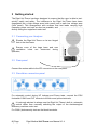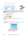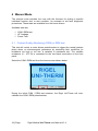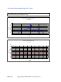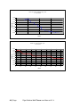
1
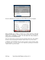
Innovating Together RIGEL UNI-THERM electrosurgical analyser Copyright © 2015 SEAWARD GROUP Last Update: 7th August 2015 Instruction Manual 398A550 Revision 1.4 Rigel Medical 24 Month Warranty Statement Rigel Medical provides a standard 12-month manufacturer’s warranty against breakdown during normal use. This warranty can be upgraded to a 24-month warranty (terms and conditions apply*). Problems caused through misuse, damage, fair wear & tear, consumables and accessories are excluded from standard warranty. Such components found to be being used in excess of their manufacturer’s operating recommendations are also excluded. Shipping to an authorised service centre is the responsibility of the sender. *Terms and Conditions of 24 Month Warranty The Rigel product must be registered with Rigel Medical within 30 days of purchase to be eligible for the extended 24-month warranty. Instruments must be returned to an authorised service centre complete with proof of purchase within 13 months of purchase for calibration at the current rate. Any items returned for calibration outside of the 13 month period stated above may not be eligible for the second 12 month section of warranty. The second 12 month section of the warranty begins at the expiry of the initial 12 month period, not when the unit is calibrated. Details correct at time of going to print. The manufacturer retains the right to make amendments to the above terms and conditions without prior notice. Calibration Statement The Rigel Uni-Therm Electrosurgical Analyser is fully calibrated and found to be within the specified performance and accuracy at the time of production. The Seaward Group provides its products through a variety of channels; therefore it may be possible that the calibration date on the provided certificate may not represent the actual date of first use. Experience has indicated that the calibration of this instrument in not effected by storage prior to receipt by the user. We therefore recommend that the recalibration period be based on a 12 month interval from the first date the unit is placed in to service. Date received into service; i / / . © Copyright 2015 All rights reserved. Nothing from this edition may be multiplied, or made public in any form or manner, either electronically, mechanically, by photocopying, recording, or in any manner, without prior written consent from the SEAWARD GROUP. This also applies to accompanying drawings and diagrams. Due to a policy of continuous development the SEAWARD GROUP reserves the right to alter the equipment specification and description outlined in this publication without prior notice and no part of this publication shall be deemed to be part of any contract for the equipment unless specifically referred to as an inclusion within such contract. ii Disposal of old product The Rigel Uni-Therm has been designed and manufactured with high quality materials and components, which can be recycled and reused. When this symbol is attached to a product it means the product is covered by the European Directive 2012/19/EC. Please familiarise yourself with the appropriate local separate collection system for electrical and electronic products or contact your local supplier for further information. Please dispose of this product according to local regulations. Do not dispose of this product along with normal waste material. By offering your old products for recycling, you will help prevent potential negative consequences for the environment and human health. iii Certificate of Conformity This product is manufactured by: Seaward Electronic Ltd, Bracken Hill, South West Industrial Estate, Peterlee, County Durham, SR8 2SW, UK Statement of Conformity As the manufacturer of the apparatus listed, declare under our sole responsibility that the product: Rigel Uni-Therm Electrosurgical Analyser To which the declaration relates are in conformity with the relevant clauses of the following standard: BS EN 61010-1 - Safety requirements for electrical equipment for measurement, control, and laboratory use - Part 1: General requirements. BS EN 61326 - Electrical equipment for measurement, control, and laboratory use - EMC requirements. Performance: The instrument operates within specification when used under the conditions in the above standards EMC and Safety Standards. The product identified above conforms to the requirements of Council Directive 2004/108/EC and 2006/95/EC. This Conformity is indicated by the symbol , i.e. “Conformité Européenne” Seaward Electronic Ltd. is registered under BS EN ISO9001:2008 Certificate No.: Q05356. iv Index 1 2 3 4 5 Introduction .............................................................................................................. 3 1.1 Analyser Functions ....................................................................................................... 3 1.2 Key Features ................................................................................................................ 4 1.3 Unpacking the Uni-Therm ............................................................................................ 4 1.4 Optional Accessories .................................................................................................... 4 1.5 Warnings and Cautions ................................................................................................ 5 1.6 User Notes ................................................................................................................... 5 1.7 Safety Notes ................................................................................................................ 5 Uni-Therm Overview ................................................................................................. 7 2.1 Simulation panel .......................................................................................................... 8 2.2 Side panel .................................................................................................................... 8 Getting started ......................................................................................................... 9 3.1 Connecting your Analyser............................................................................................. 9 3.2 Rear panel ................................................................................................................... 9 3.3 Simulation connection panel ........................................................................................ 9 3.4 Side panel ESU to ESA connections ............................................................................. 10 3.5 Home screen.............................................................................................................. 10 Manual Mode ......................................................................................................... 11 4.1 Contact Quality Monitoring (CQM) or REM test .......................................................... 11 4.2 HF Leakage ................................................................................................................ 13 4.3 Power Test ................................................................................................................ 15 Automatic Mode ..................................................................................................... 21 5.1 6 Stopping or Failing a Test Sequence ............................................................................ 25 Data ....................................................................................................................... 26 6.1 View Data .................................................................................................................. 27 6.2 Transfer Data ............................................................................................................. 28 6.3 Download Data .......................................................................................................... 28 6.4 Upload Data .............................................................................................................. 30 6.5 Import Power Reference Curves ................................................................................. 31 6.6 Transfer Test Sequences ............................................................................................. 32 7 Bluetooth Favourites ............................................................................................... 33 8 Setup ...................................................................................................................... 35 8.1 Test Sequence............................................................................................................ 36 8.2 Time Date ................................................................................................................ 41 1 | Page Rigel Medical Uni-Therm user Manual V1.4 9 8.3 Language ................................................................................................................... 41 8.4 Factory Restore.......................................................................................................... 42 8.5 About ........................................................................................................................ 43 Maintaining the Rigel Uni-Therm ............................................................................ 44 9.1 Cleaning the Analyser ................................................................................................ 44 9.2 User Maintenance...................................................................................................... 44 9.3 Firmware Upgrade ..................................................................................................... 44 9.4 Return Instructions. ................................................................................................... 45 10 Specifications .......................................................................................................... 46 10.1 Technical Specification ............................................................................................... 46 10.2 General Specification ................................................................................................. 47 10.3 Load Power rating Rigel Uni-Therm ............................................................................ 48 11 Support ................................................................................................................... 50 11.1 Contact Us ................................................................................................................. 50 12 Appendix A IEC 60601-2-2 Leakage Tests ................................................................ 51 13 Appendix B Additional Leakage Tests ...................................................................... 55 14 Appendix C IEC 60601-2-2 Power Tests .................................................................... 57 15 Appendix D Creating a power reference curve ........................................................ 58 16 Appendix E Firmware Route Map ............................................................................ 60 2 | Page Rigel Medical Uni-Therm user Manual V1.4 1 Introduction Thank you for purchasing the Rigel Uni-Therm Electrosurgical Analyser. The new high performance Rigel Uni-Therm accurately measures the performance of electrosurgical generators. Measurements include; high frequency leakage, high power current and power distribution, and patient return plate alarm testing. A newly designed ultra-low inductive load bank provides highly accurate and stable test conditions at high frequency currents. Utilising a large, full colour graphical display, the Rigel Uni-Therm is a fully standalone electrosurgical analyser that can offer true intuitive, user friendly operation and operator safety. Tests can be carried out on an individual basis (see chapter 2) and as part of an automatic sequence (see chapter 3). Data can be stored, viewed and transferred from within the instrument (see chapter 4). Customisation of the Rigel Uni-Therm can be carried out in the setup (see chapter 6). 1.1 Analyser Functions The Rigel Uni-Therm is able to measure the following parameters both automatically and manually; Power Test (W, mA rms, V peak and crest factor) HF Leakage (mA rms) Peak and Peak to Peak voltage Plate Security (CQM) or return electrode monitoring (REM) For the power test, an internal array of resistors provide a safe variable load of 05115Ω in 5Ω steps; enabling the production of accurate and detailed power distribution curves, with an instant tabular view of test results. A unique feature of the HF leakage test is on screen graphics illustrating correct test connection configurations, complete with user set pass fail limits. The plate security (CQM) test offers a unique isolated, motor driven potentiometer, which provides a continuous swept resistance change; enabling accurate and fast testing of alarms, complete with user set pass fail limits. Any future firmware upgrade can be efficiently installed by users, without risk to stored data. The new Rigel Uni-Therm forms part of a comprehensive range of high performance specialist biomedical test equipment supplied by Rigel Medical, part of the Seaward Group. 3 | Page Rigel Medical Uni-Therm user Manual V1.4 1.2 Key Features Fully compliant with IEC 60601-2-2 – One instrument for full compliance testing offering peace of mind Accurate and Safe – Utilising full 10kV isolation on all measuring systems High current test capability – Allows accurate calibration and measurement of currents up to 8A. High Frequency Leakage – Easy to connect with on screen help for each configuration Power distribution curves - Variable load with full 10kV isolation from 0 to 5115Ω in 5Ω steps – Accurate, fast, and flexible Voltage measurements: RMS, Peak as well as Peak to Peak voltage Plate Security (CQM) test – using electronic potentiometer range up to 475Ω in 1 Ω steps with high and low alarms Stand-alone – Not relying on PC or laptop. Stylish and rugged enclosure – with small footprint ideal for in-situ testing Graphic colour user interface - for fast and easy navigation and connection to DUT Future upgrade ready – download future upgrades from the web into your tester 1.3 Unpacking the Uni-Therm Carefully unpack all items from the box and ensure the following items are included: Rigel Uni-Therm Electrosurgical Analyser Mains Power Lead Calibration Certificate Uni-Therm Quick Start Guide Utilities Disc USB Cable 3 x Jumper Links (p/n 43B759) 1.4 Optional Accessories Foot switch adaptor cable set (manufacturer specific, please specify) Trolley style hard carry case SMB to BNC Oscilloscope connection lead (p/n 367A950) Full accessory list available at: http://www.rigelmedical.com/downloads/Rigel-Uni-Therm-AccessoryDatasheet-Rev1-2.pdf 4 | Page Rigel Medical Uni-Therm user Manual V1.4 1.5 Warnings and Cautions Before you power up - Ensure the mains switch positioned at the base panel of the Rigel Uni-Therm is set to the appropriate voltage range i.e. 230VAC or 120 VAC. Before you power up - Ensure none of the ventilation holes are covered during operation including the ones on the base panel. We strongly recommend positioning the Rigel Uni-Therm on its two hinged feet at the front base. 1.6 User Notes The following symbols are used throughout this Instruction Manual. Warning of electrical danger! Indicates instructions must be followed to avoid danger to persons. Important, follow the documentation! This symbol indicates that the operating instructions must be adhered to in order to avoid danger. When operating the Rigel Uni-Therm at its maximum capability, in ambient temperature of 40°C and only during certain power tests, the surface temperature of the top cover may exceed temperatures of 50°C but not exceed a surface temperature of 70°C as is permitted under the IEC 61010 design requirements. Do not connect any active power electrodes to the simulation panel of the Rigel Uni-Therm. Failure to comply with this will void the warranty and might lead to internal damage of circuits. 1.7 Safety Notes The Rigel Uni-Therm Electrosurgical Analyser is designed for use by adequately trained technical personnel only. The Rigel Uni-Therm Electrosurgical Analyser is designed for use within the published specifications. Any application outside of these specifications or any unauthorised user modifications may result in hazardous conditions or improper operation and will void the product warranty. 5 | Page Rigel Medical Uni-Therm user Manual V1.4 Operation - Refer to the Device Under Test (DUT) manufacturer operating instructions to ensure safe operation whilst analysing the DUT Safety - Use extreme caution when working with voltages greater than 30 Volts. Safety - Where safe operation of the Uni-Therm is no longer possible it should be immediately shut down and secured to prevent accidental operation. It must be assumed that safe operation is no longer possible: if the instrument or leads show any sign of damage or the instrument does not function or after long periods of storage under adverse environmental conditions. 6 | Page Rigel Medical Uni-Therm user Manual V1.4 2 Uni-Therm Overview 6 1 2 7 3 4 5 8 1. 2. 3. 4. 7 | Page ON / OFF button Function keys (F1-F4) Start / Confirm key (Green) Rotary encoder / main navigation key 5. 6. 7. 8. Simulation panel Colour screen Stop / Cancel key (Red) Hinged feet Rigel Medical Uni-Therm user Manual V1.4 2.1 Simulation panel 1 3 2 1. CQM/ REM output connection (Black) 2. CUT footswitch control output (Yellow) 3. COAG footswitch control output (Blue) Do not connect any active power electrodes to the simulation panel of the Rigel Uni-Therm. Failure to comply with this will void the warranty and might lead to internal damage of circuits. 2.2 Side panel 1. Variable load bank connections (Red & Black) 2. Oscilloscope output* 3. Measuring Device connections (White) 4. HF Leakage connections *Note; The scope output (SMB connector) provides an 10kV isolated waveform monitoring output however the scope output is not calibrated. 8 | Page Rigel Medical Uni-Therm user Manual V1.4 3 Getting started The Rigel Uni-Therm has been designed to ensure that the user is able to test: quickly, easily and safely. The interfaces to the Rigel Uni-Therm have been segregated into a high-voltage area (side panel) and a safe low voltage area (front panel). This arrangement also ensures that test leads carrying high frequency power are kept as short as possible, and directly facing the equipment under test. 3.1 Connecting your Analyser Elevate the Rigel Uni-Therm on its two hinged feet at the front base. Ensure none of the large base and rear ventilation inlets are obstructed during operation, 3.2 Rear panel Connect the mains cable to the IEC connector on the rear panel. 3.3 Simulation connection panel For automatic control during HF leakage and Power tests, connect the ESU footswitch COAG and CUT contacts to the blue and yellow terminals. It is strongly advised to always use the Rigel Uni-Therm’s built-in, automatic control rather than manually switching the output of the electrosurgical diathermy machine under test. For CQM / plate security test use the black terminals. 9 | Page Rigel Medical Uni-Therm user Manual V1.4 3.4 Side panel ESU to ESA connections Follow the on-screen instruction diagrams for correct test connection. See appendices A and B for embedded connection diagrams. Connect the ESU active and neutral electrodes to the side panel as indicated, also fit jumper links (positions 1, 2, 3, 4) as required to complete circuits. NB: each connection diagram has a unique reference code. eg ‘1112’ for identification. 3.5 Home screen Upon power-up of the Rigel Uni-Therm, the display will be showing the HOMESCREEN; 10 | Page ON F1 F2 F3 F4 / OFF butt on Rigel Medical Uni-Therm user Manual V1.4 4 Manual Mode The manual mode provides the user with the features for testing a specific individual function and or test condition; for example to aid fault diagnostic procedures. These tests are available from the home screen. Available tests are: CQM / REM test HF Leakage Power Test 4.1 Contact Quality Monitoring (CQM) or REM test This test will control a motor driven potentiometer to trigger the neutral (patient plate) alarm on electrosurgical generators by simulating fault conditions (ie resistance too high or too low, a variation in resistance etc). The variable resistance (0 – 475 Ω) is connected to the two black connectors on the front panel. Select the CQM / REM test from the home screen shown below. During the initial CQM / REM test selection, the Rigel Uni-Therm will autocalibrate the CQM / REM potentiometer; 11 | Page Rigel Medical Uni-Therm user Manual V1.4 Once the calibration has completed, the CQM / REM test screen will appear; Select automatic (up or down) or manual (up or down) control by using the dedicated AUTO MAN key. This key is also used to set the limits. Once the SET LIMITS field is highlighted in green, use and press the rotary encoder to manipulate the UP and DOWN limits. Press the Green button to start the test (for automatic mode only). Then capture the alarm value by pressing the dedicated ‘Capture Alarm’ key on the screen. In MANUAL UP and DOWN mode, the rotary encoder is used to directly control the potentiometer. The alarm value is then captured by pressing the dedicated ‘Capture Alarm’ key on the screen. 12 | Page Rigel Medical Uni-Therm user Manual V1.4 4.2 HF Leakage The HF Leakage test measures the HF leakage current in various test configurations (see appendix A), and compares the result to a user set pass/fail value. Select the HF LEAKAGE test from the main menu, shown below. Use the rotary encoder to navigate the screen Select the required setting and press the rotary encoder to activate the field. Once activated, use the rotary encoder to change the settings. Confirm and deactivate the field by pressing the encoder once again. START DELAY will allow the user to set a measurement delay for generators operating in a soft start mode. The TEST TIME will display the total test time of the leakage test and dictate the amount of tests done as a result of the selected ON TIME and OFF TIME. Note: the D/CYCLE is limited to 50% or less during the leakage test with a maximum ON time of 15 seconds. To increase the ON TIME, the OFF TIME must be increased first in order to remain within the duty cycle limits. This is done to protect the EUT from overheating. If the selected ON / OFF time is above the 50% duty cycle (the Uni-Therm will calculate this automatically), the duty cycle factor appears in red. It’s not possible to continue without reducing the duty cycle. A valid duty cycle will appear in black. 13 | Page Rigel Medical Uni-Therm user Manual V1.4 Press NEXT to confirm and start selecting the appropriate leakage tests. Four different measurement scenarios have been described in the particular standard IEC 60601-2-2; See appendix A for all available leakage settings. Use the rotary encoder to change between the different leakage configurations. Use either the DIAGRAM mode, shown below. or the IEC 60601-2-2 reference details (SHOW DETAIL). The rotary encoder can be used to scroll the different test setups, or to SET LOAD and LEAKAGE LIMIT values. The selected field is highlighted in red. Press the rotary encoder to activate the field (field turn blue) and use the rotary encoder to change the settings. Press the rotary encoder again to confirm Return to the DIAGRAM mode by using the SHOW DIAGRAM fast key. Start the test by pressing the RUN button, and confirm with the green START button on the front of the Uni-Therm; 14 | Page Rigel Medical Uni-Therm user Manual V1.4 The Rigel Uni-Therm could display the following details after the test; Press the HOLD key to freeze the reading on the screen. The test can be aborted by pressing the red STOP button on the front of the Uni-Therm. After a test is completed (either PASS or FAIL) press the green START button on the front of the Uni-Therm. 4.3 Power Test The output power of the Active Electrodes (CUT / COAG and BIPOLAR) is measured, either at a fixed load (Continuous Single Test) or at a range of loads (Power Distribution Graph). The load will vary from a start value to an end value with a number of intervals (resolution). The Rigel Uni-Therm will control the EUT by using the internal footswitch controller. 15 | Page Rigel Medical Uni-Therm user Manual V1.4 Select Power test from the home screen; then select F2 (CONT) F3 (GRAPH) or F4 (EXT) modes using the fast keys; to select either the Continuous, Graph or External Load test. Use the rotary encoder or the dedicated function keys to navigate. 4.3.1 Continuous mode The continuous mode allows the user to monitor the power characteristics under a specific load condition. Ensure that the power settings on the EUT do not exceed those specified in the Load Power rating Rigel Uni-Therm. Use the rotary encoder to navigate the screen. The selected field is marked with a red border, presses the rotary encoder to activate the field to allow changes. Confirm and de-activate the field by pressing the encoder once again. LOAD is required to determine the resistance at which the power measurement is carried out. START DELAY will allow the user to set a measurement delay for generators operating in a soft start mode. 16 | Page Rigel Medical Uni-Therm user Manual V1.4 The TEST TIME will display the total test time of the leakage test and dictate the amount of tests done as a result of the selected ON TIME and OFF TIME. The BIPOLAR / MONO POLAR and COAG / CUT settings determine the type of connection diagrams when the SHOW DIAGRAM button is pressed. The COAG / CUT settings also determine the activation of the foot paddle control on the front of the Uni-Therm. Note: the duty cycle is limited to 50% or less when the high duty cycle box is unticked to protect the EUT from overheating. It is however possible to obtain up to 60 seconds on time. For this to happen the high duty cycle box must be ticked. To increase the on time, the off time must be increased first in order to remain within the duty cycle limits. This is done to protect the EUT from overheating. Press SHOW DIAGRAM to obtain help on the connection between the Uni-Therm and the EUT. Press START to confirm the settings and start the test. During the Continuous power test, the display will show continuously updated readings. Press the HOLD button to freeze the display 17 | Page Rigel Medical Uni-Therm user Manual V1.4 4.3.2 Graph Mode The graph mode allows the user to monitor the power characteristics under a range of loads. Ensure that the power settings on the EUT do not exceed those specified in the Load Power rating Rigel Uni-Therm. Use the rotary encoder to navigate the screen. The selected field is marked with a red border, presses the rotary encoder to activate the field to allow changes. Confirm and de-activate the field by pressing the encoder once again. START LOAD is required to determine the starting resistance at which the power curve measurement is carried out. START DELAY will allow the user to set a measurement delay for generators operating in a soft start mode. END LOAD, will set the highest resistance at which the power curve measurement is carried out. TEST POINTS, determines the number of test points (resolution) of the power distribution graph. The higher the number, the more detailed the power distribution graphs. The TEST TIME will display the total test time of the leakage test and dictate the amount of tests done as a result of the selected ON TIME and OFF TIME and the number of test points. The BIPOLAR / MONO POLAR and COAG / CUT settings determine the type of connection diagrams when the SHOW DIAGRAM button is pressed. The COAG / CUT settings also determine the activation of the foot paddle control on the front of the Uni-Therm. 18 | Page Rigel Medical Uni-Therm user Manual V1.4 Note: the duty cycle is limited to 50% or to protect the EUT from overheating. To increase the ON time, the OFF time must be increased first in order to remain within the duty cycle limits. Press SHOW DIAGRAM to obtain help on the connection between the Uni-Therm and the EUT. Press START to confirm the settings and start the test. During the Graph power test, the Rigel Uni-Therm will display the power distribution graph. At the end of the test, toggle between GRAPH MODE and DATA by pressing the GOTO DATA fast key In the automatic mode, a reference graph can be included in the test to automatically detect of the current graph meets the criteria of the reference graph. A full description of how to create a power reference graph is provided in Appendix D. 4.3.3 External Load Mode The external load mode allows the user to monitor the power characteristics under a specific load condition, utilising external loads or under short circuit condition i.e. for calibration purpose. During the test, the EUT is connected to the external loads and then to the measuring device of the Uni-Therm (MD). The UniTherm will calculate the power characteristics at the set external load by measuring the HF current through the MD. The maximum current measurement during this test is limited to 8A rms. 19 | Page Rigel Medical Uni-Therm user Manual V1.4 Use the rotary encoder to navigate the screen. The selected field is marked with a red border, presses the rotary encoder to activate the field to allow changes. Confirm and de-activate the field by pressing the encoder once again. EXT LOAD is required to determine the correct power calculation and is for reference only. The Uni-Therm’s load bank is not part of the test setup. START DELAY will allow the user to set a measurement delay for generators operating in a soft start mode. The TEST TIME will display the total test time of the leakage test and dictate the amount of tests done as a result of the selected ON TIME and OFF TIME. The BIPOLAR / MONO POLAR and COAG / CUT settings determine the type of connection diagrams when the SHOW DIAGRAM button is pressed. The COAG / CUT settings also determine the activation of the foot paddle control on the front of the Uni-Therm. Note: the duty cycle is limited to 50% or to protect the EUT from overheating. To increase the ON time, the OFF time must be increased first in order to remain within the duty cycle limits. Press SHOW DIAGRAM to obtain help on the connection between the Uni-Therm and the EUT. Press START to confirm the settings and start the test. 20 | Page Rigel Medical Uni-Therm user Manual V1.4 5 Automatic Mode The automatic mode allows the user to select a test sequence which will carry out a pre-determined set of tests against user definable limits. Test results are stored at the end of the test for future reference. To view or transfer stored data, please refer to chapter 6) To enter the automatic mode, select the MENU key (F1) from the home screen and then AUTOMODE; In the following screen, an asset ID number can be entered using the rotary encoder, barcode scanner or a PS2 keyboard. When using the barcode scanner, ensure the barcode scanner is paired with the Rigel Uni-Therm, see Chapter 7. (The Rigel Uni-Therm will only support the Seaward barcode scanner, p/n 339A923). When the barcode is ready to scan, the word “OK” will appear in the asset ID field. Enter data with the rotary encoder (push to select character) or keyboard (note that the enter key is not required). Press NEXT to choose an available test sequence; 21 | Page Rigel Medical Uni-Therm user Manual V1.4 Next, select the Test Sequence box (push to select) and select the required test sequence. (To add new test sequences, see Chapter 8.1). From the auto mode screen, press NEXT to start the sequence. In the example below, SEQUENCE2 will be used which was created in Chapter 8.1. The first test in SEQUENCE2 is the REM test. Use either the AUTO UP or MANUAL UP (F2) to increase the REM resistance. As soon as the EUT goes into alarm, capture the alarm by pressing CAPTURE ALARM (F3). Then continue by selecting the AUTO DOWN or MANUAL DOWN to reduce the resistance and capture the corresponding alarm. The next step is a custom test to instruct the user to disconnect the neutral electrodes. 22 | Page Rigel Medical Uni-Therm user Manual V1.4 Either press PASS (F2) or the GREEN button to continue, The next step in SEQUENCE2 is the HF leakage test; Follow the connection instructions on the main screen and press RUN to confirm and start the HF leakage test. The next step is a custom test to instruct the user to set the output power to maximum (300W) in this example. Either press PASS (F2) or the GREEN button to continue The next step in SEQUENCE2 is the POWER GRAPGH test; 23 | Page Rigel Medical Uni-Therm user Manual V1.4 The Rigel Uni-Therm will display the settings. Press SHOW DIAGRAM (F3) to show the connection diagram; Check connections and confirm by pressing START. Press the GREEN button to start the test. The Rigel Uni-Therm will now activate the EUT through the foot paddle control on the front panel. During the test, the screen will update the graph after each measurement is taken. Switch from GRAPGH to DATA (F4) mode to view actual results. 24 | Page Rigel Medical Uni-Therm user Manual V1.4 5.1 Stopping or Failing a Test Sequence During the test, the sequence can be interrupted or cancelled. Press the red button on the front panel. The following option menu will appear; Restart Test will continue the test sequence from where it was interrupted. Restart Test Sequence will start the sequence from the beginning. Next Test will skip the current test and move to the next test (note that a failure will be reported for the skipped test). End Test Sequence will stop the test sequence and store the results (fail). Abort Test Sequence will stop the test sequence. No data is stored. 25 | Page Rigel Medical Uni-Therm user Manual V1.4 6 Data Stored data can be viewed and transferred to and from the PC such as test results and power distribution reference curves. To enter the Data menu, select the MENU key (F1) from the home screen and then DATA (F3); This leads to 3 options; View data (see Chapter 6.1) Transfer data (see Chapter 6.2) BT favourites (see Chapter 7) 26 | Page Rigel Medical Uni-Therm user Manual V1.4 6.1 View Data Stored data can be viewed by selecting the VIEW (F2) from the DATA screen as shown above. Data can be sorted using the SORT (F4) key which will sort on asset number and date either ascending or descending. From the view data screen, results and test sequences can be viewed by pressing the VIEW button and transferred to a PC by pressing TRANSFER; To view data, use the rotary encoder to select the asset ID, press to select or press VIEW (F2). This shows the test results for the selected asset ID; Test results can be viewed by pressing the RESULTS (F2) button, test settings can be viewed by pressing TEST SEQ (F3) button and deleted by pressing the DELETE (F4) button. When power distribution graphs are part of the test sequence, the results can be displayed in graph mode and data mode, see below. In graph mode, the reference graph is also shown; 27 | Page Rigel Medical Uni-Therm user Manual V1.4 6.2 Transfer Data The Rigel Uni-Therm is able to transfer data to and from the PC. In addition, power distribution reference curves can be uploaded to the instrument, to allow quick check of power performance against manufacturer curves. 6.3 Download Data Stored data can be downloaded to the PC in several formats. To capture data as a text file (CSV), select either CSV full or CSV summary. To download the test results into Med-eBase, select the SSS format. 28 | Page Rigel Medical Uni-Therm user Manual V1.4 Change the data format between Export SSS, Export CSV Full, Export CSV Summary, Export Test Sequences, Import Results, Import Ref Graph and Import Test Sequences by pressing the OPERATION (F2) button. Change between USB, USB Memory Stick, using the PORT (F3) key. Start Download by pressing START (F4). Note that for the EXPORT SSS format must be selected when data is downloaded to Med-eBase software. The Rigel Uni-Therm will act as a REMOVABLE DISC data storage device and the data file can be copied from the drive that appears in explorer. Note that when using Med-eBase, the export and import of data will commence from the software once the Uni-Therm is in the TRANSFER READY state. Results for Med-eBase will have the file name Results_01012015_109837.sss with the numbers indicating the date and time of download. All results stored on the unit will be downloaded in one file. Sequences for Med-eBase will have the file name Sequences_01012015_109837.sss with the numbers indicating the date and time. All Sequences from the unit will be downloaded in one file. 29 | Page Rigel Medical Uni-Therm user Manual V1.4 6.4 Upload Data Test data can be uploaded to the Rigel Uni-Therm by adding downloaded files (see data download above) into the folder that appears in the explorer window. Using Med-eBase software, work and assets can be scheduled (see Med-eBase user manual) Change between USB Memory Stick or Cable, using the PORT (F3) key. Start upload by pressing F4 (Start) (refer to Med-eBase user manual for procedures on Med-eBase) When the Uni-Therm is put in the upload menu / data transfer, the Uni-Therm will appear as a removable drive. Copy the test results information into the test results folder. The data has now been uploaded to the Uni-Therm. 30 | Page Rigel Medical Uni-Therm user Manual V1.4 Sequences for Med-eBase will have the file name Sequence_01012015_109837.sss with the numbers indicating the date and time. All Sequences will be uploaded in one file. 6.5 Import Power Reference Curves To assist with the power distribution graph tests, expected or reference curves can be uploaded to the instrument for quick comparison. An upper and lower limit graph can be uploaded by selecting “Import Ref Graph” on the data transfer screen. Use OPERATION (F2) to change. Change between USB Memory Stick or Cable, using the PORT (F3) key. When using Med-eBase to upload the reference curves, refer to the Med-eBase user manual for procedures. When using Windows Explorer, press START and locate the REMOVABLE DISC. Copy the reference curve .sss files into the corresponding folder. This has now stored the reference curves on the Rigel Uni-Therm. Please see application note 0031 - Upload Reference Curve to Rigel Uni-Therm for more details on creating curves. 31 | Page Rigel Medical Uni-Therm user Manual V1.4 6.6 Transfer Test Sequences Test sequences can be created on both the Rigel Uni-Therm and in Med-eBase software. Test sequences can then be shared across a number of Rigel UniTherm’s in order to have identical configuration of test sequences. Export test sequences from the data transfer screen, select the Export Test Sequences (press OPERATION F2). Press start to connect the Uni-Therm as an external drive to the PC. Using Med-eBase, import the test sequences by following the instructions in the Med-eBase instruction manual. When using windows Explorer, locate the REMOVABLE DISC and navigate to the corresponding folder; Select the Sequence file and copy to the folder of choice. The file can then be shared between other PC’s and uploaded back into other Uni-Therm units. To import the test sequence(s), put the sequence in the corresponding folder as shown above. The new test sequences will now appear in the Uni-Therm test sequence library. Sequences for Med-eBase will have the file name Sequence_01012015_109837.sss with the numbers indicating the date and time. 32 | Page Rigel Medical Uni-Therm user Manual V1.4 7 Bluetooth Favourites In order for the Rigel Uni-Therm to automatically connect to the correct Bluetooth accessory, details of that accessory must be stored into the Bluetooth Favourites list (pairing). The Bluetooth Favourites list is compatible with the Barcode scanner only : Barcode (Scanner) To start the pairing process, select DATA from the home screen, followed by BT FAVOURITES. From the BT Favourites screen, press the SEARCH button to list all the Bluetooth devices within reach. (Ensure your device is in “discovery” mode.) 33 | Page Rigel Medical Uni-Therm user Manual V1.4 The devices found in range will be listed. Wait until the search has been completed which can take up to 15 seconds. Once the search is completed, press the back arrow key; To pair the appropriate device to the corresponding function, select and open the drop down box using the rotary encoder and press SELECT for each correct device; Check that the correct devices are paired for each function and press the back arrow to exit and complete the pairing; Note If the required device is not shown, check that it is powered on with the Bluetooth function active then repeat the search. Some Bluetooth devices do not report a recognisable name and may cause confusion when setting up Favourites. Turn off or disable unused Bluetooth devices when configuring Favourites. Note Seaward and Rigel accessories do not require a PIN. When the PC requires an authorisation (some Windows version might ask), enter 0000 (four zero’s) 34 | Page Rigel Medical Uni-Therm user Manual V1.4 8 Setup To enter the setup mode, select the MENU key (F1) from the home screen and then SETUP; The SETUP menu allows the user to customise the Rigel Uni-Therm; View, edit or create test sequences, see chapter 6.1 Configure the local time and date settings, see chapter 6.2 Change the menu language, see, see chapter 6.3 Restore factory settings, see chapter 6.4 View the about screen, see chapter 6.5 35 | Page Rigel Medical Uni-Therm user Manual V1.4 8.1 Test Sequence The Rigel Uni-Therm can be set-up to perform automatic test sequences. These can be created by the user and can be specific to for example; manufacturers recommendations. The total number of possible test sequences is 100. From SETUP menu, select the test sequence option; 8.1.1 Creating a new test sequence Select test sequences from the SETUP menu; Select NEW (F2) to open a new test sequence and enter a name, use the rotary encoder or USB keyboard to enter data; Select KEYBOARD to change the format from QWERTY to ABCD style; Press the GREEN button to confirm or RED button to cancel. 36 | Page Rigel Medical Uni-Therm user Manual V1.4 Press the EDIT (F3) button to open the test sequence for editing; Note; when no individual tests are inserted, the EDIT and OPTIONS buttons are not active Start adding individual tests to the test sequence by pressing the ADD (F2) button; Highlighted the required test using the rotary encoder and press to select; 37 | Page Rigel Medical Uni-Therm user Manual V1.4 Repeat the above steps until the required test sequence is completed. Note that additional tests can be inserted in the test sequence by highlighting the position in the sequence and press the ADD (F2) button. The test will be inserted AFTER the highlighted position. The individual tests can now be edited / configured to the specific requirements. Once an individual test has been configured, they can be copied and pasted repeatedly by selecting the OPTIONS button. Edit individual tests by selecting the required test and press EDIT (F3); 38 | Page Rigel Medical Uni-Therm user Manual V1.4 Once the selected criteria have been set, confirm by pressing the UPDATE (F4) button. User tests can be inserted and used for providing instructions to the test engineer. Select the user test and press EDIT (F3); In the user test screen, select the field you want to edit which is highlighted with a red border. Press the rotary encoder to open the field for editing; In case the user test requires data entry such as a result, the user test can also include an engineer unit such as Ohms, Watts, Celsius etc. Confirm the entry by pressing the UPDATE button. Once the test sequence is completed, press the back arrow key and confirm the changes: The new test sequence has now been added to the test library; 39 | Page Rigel Medical Uni-Therm user Manual V1.4 Edit Sequence Name, Copy or Delete the test sequence from the Test Sequences menu, select OPTION; To delete a test sequence, press DELETE To copy a test sequence, press COPY To rename a test sequence, RENAME 40 | Page Rigel Medical Uni-Therm user Manual V1.4 8.2 Time Date To modify the time or date including time format (12 / 24h clock), select the Time / Date (F3) option in the setup menu; Press 24H (F2) to change between 12H (AM/PM) and 24H clock format. Press MM/DD (F3) to change between MM/DD and DD/MM format. Use the rotary encoder to navigate, push to activate field and change values using the rotary encoder. Press SAVE to confirm. 8.3 Language To change the language, select the language option in the setup menu, see below; Use the rotary encoder to navigate, push to select the language. Press the back button (F1) to confirm or return to previous menu. The list of languages might change from that in this manual as they are continuously updated. 41 | Page Rigel Medical Uni-Therm user Manual V1.4 8.4 Factory Restore Restore instrument to factory default settings can delete all user created test sequences, reference graphs and can also be used to clear the memory. The user is given an option to select which part of the memory is being restored to the factory default. To restore factory default, select the factory restore option in the setup menu, see below; An overview of the memory usage is provided; Press NEXT to select which part of the memory to restore to factory default; Use the rotary encoder to select which part of the memory is being affected. Individual assets can be deleted from the view data menu, see chapter 4.1 42 | Page Rigel Medical Uni-Therm user Manual V1.4 8.5 About The about screen shows the firmware versions and serial number of your device. Ensure you have this information available when contacting Rigel Medical for Technical Support or Service. See chapter 7.4 for more information on Service and Calibration. 43 | Page Rigel Medical Uni-Therm user Manual V1.4 9 Maintaining the Rigel Uni-Therm 9.1 Cleaning the Analyser The Rigel Uni-Therm case can be cleaned with a damp cloth with, if necessary, a small amount of mild detergent. Prevent excessive moisture around the socket panel. Do not allow liquid inside the Rigel Uni-Therm or near the sockets. Do not use: abrasives, solvents, or alcohol. If any liquid is spilt into the Rigel Uni-Therm case, the analyser should be returned for repair, stating the cause of the defect. 9.2 User Maintenance The Rigel Uni-Therm is a rugged quality instrument. However, care should always be taken when using, transporting and storing this type of equipment. Failure to treat the product with care will reduce both the life of the instrument and its reliability. If the Rigel Uni-Therm is subject to condensation, allow the Analyser to completely dry before use. Always check the Rigel Uni-Therm and all test leads for signs of damage and wear before use. Do not open the Rigel Uni-Therm under any circumstances. Keep the instrument clean and dry. Avoid testing in conditions of high electrostatic or electromagnetic fields. Maintenance should only be performed by authorised personnel. Apart from the mains cable and fuses, there are no user replaceable parts in the Rigel Uni-Therm. The unit should be regularly calibrated. 9.3 Firmware Upgrade The Rigel Uni-Therm is designed to allow service agents and users to easily upgrade the firmware by using the internet to download: the latest firmware, a loading application, and instructions. The firmware is installed using a PC via the USB port or via a USB stick. To obtain the latest firmware, the Rigel Uni-Therm will need to be registered; this will also provide automatic upgrade alerts to the user. 44 | Page Rigel Medical Uni-Therm user Manual V1.4 9.4 Return Instructions. For repair or calibration return the instrument to:Rigel Medical Service Dept., p.a. Calibration House Bracken Hill South West Industrial Estate Peterlee, Co. Durham SR8 2SW, England Tel : +44 (0)191 587 8739 Fax: +44 (0)191 586 0227 [email protected] [email protected] www.calibrationhouse.com www.rigelmedical.com Prior to returning your unit for service, please contact our service department to obtain a Returns Number. By obtaining a Returns Number, your service request can be booked in advance thus reducing the down time of your equipment. When asking for a Returns Number, please quote: Instruments name and model Serial number Firmware version 45 | Page Rigel Medical Uni-Therm user Manual V1.4 10 Specifications 10.1 Technical Specification HF Power Watt (RMS) Accuracy True RMS Watts (0 -500W) Refer to load/power graph ±(1W +5% of reading) Accuracy 0 – 6000mA with load bank 0 – 8000mA external load test ±(2% of reading +10mA) Voltage (RMS) Accuracy 0 - 700V ±(10% of reading +5V) Voltage (peak) Accuracy 0 – 10KV (Peak) – Closed load only ±(10% of reading + 15V). Crest Factor 1.4 – 20 (± Vpeak / V RMS) The higher of the 2 peak voltage measurements is used. RMS Bandwidth (instrument only) RMS Bandwidth (with load bank) Interference Frequency Filter Isolation (earth to measurement device) 30 Hz to 10MHz MHz (-3 dB) 30 Hz to 2.5 MHz (-3 dB) 100 Hz high pass filter 10kV Measurement delay adjustment Foot switch delay selectable between 200 – 5000ms (10ms resolution) Variable Load Load Resistor Type Accuracy Power rating Duty cycle 0 - 5115Ω, steps @ 5Ω Ceramic Resistors (Non inductive) ±(1%, + 0.5, -0.5 Ω of set load) See load/power graph Up to 100% at 60 seconds ON time, see load/power graph Fixed Loads Accuracy Power rating 2 x 200Ω ±1%, + 0.5,-0.0 Ω 20 Watt (100% duty cycle) Plate Security (REM) resistor 0 - 475Ω, 1Ω step Motor driven potentiometer ±5% ± 2 Ω High and low, manual confirmation Manual or automatic HF Current (RMS) Accuracy Alarm register Ranging 46 | Page Rigel Medical Uni-Therm user Manual V1.4 Oscilloscope output 0.5V/A, 100mA RF current minimum input, un-calibrated , indication only Connections Variable load 0 – 5115Ω Fixed Load x 200Ω 2 x 4mm Red = Active, Black = Plate 1 x 4 mm black (common), 2 x 4 mm red 2 x 4mm White SMB coaxial connector Measuring device (MD) Oscilloscope output REM test 0-475 ohm Remote foot switch control (CUT) Remote (COAG) foot switch control USB B port USB A port 2 x 4 mm – black 2 x 4 mm - yellow, Single relay contact 2 x 4 mm - blue, Single relay contact PC interface Key board Data Storage and Recall Memory Output 4Mb CSV format, sss, test sequences, results, reference power graphs. 10.2 General Specification Dimensions Weight Operating Temperature Storage Temperature Mains power Fuses 47 | Page 370 X 300 X 204mm 11 Kg 10 ˚C to 40 ˚C 0˚C to 50 ˚C 115/230 ±10% VAC; 48 to 66 Hz, 35 VA 2 x 1.6 A (T) ceramic Rigel Medical Uni-Therm user Manual V1.4 10.3 Load Power rating Rigel Uni-Therm External Load mode Current Limit = 8 A rms No power rating (user supplied Load) Max Watts at 15sec On / 15sec Off 50% duty cycle 5 - 5115 ohms 1600 1400 Watts 1200 1000 800 600 400 200 0 1 10 100 1000 10000 Ohms Max Watt at 60sec On / 15sec Off duty cycle 5 - 100 ohms 900 800 700 Watts 600 500 400 300 200 100 0 5 15 25 35 45 55 65 75 Ohms 48 | Page Rigel Medical Uni-Therm user Manual V1.4 85 95 Max Amps at 15sec On / 15sec Off 50% duty cycle 5 - 5115 ohms 7.00 6.00 Amps rms 5.00 4.00 3.00 2.00 1.00 0.00 1 10 100 1000 10000 Ohms Max Amps at 60sec On / 15sec Off duty cycle 5 - 100 ohms 5.00 4.50 4.00 Amps rms 3.50 3.00 2.50 2.00 1.50 1.00 0.50 0.00 5 15 25 35 45 55 65 75 Ohms 49 | Page Rigel Medical Uni-Therm user Manual V1.4 85 95 11 Support 11.1 Contact Us Rigel Medical Contact details Rigel Medical Address details Sales and Delivery enquiries Tel: +44 (0) 191 587 8730 Fax: +44 (0) 191 586 0227 Email: [email protected] Rigel Medical 15 - 18 Bracken Hill South West Industrial Estate Peterlee, County Durham SR8 2SW, United Kingdom Technical enquiries Tel: +44 (0) 191 587 8701 Email: [email protected] CalibrationHouse Contact details CalibrationHouse Address details Service, Calibration and Repair Tel: +44 (0) 191 587 8739 Fax: +44 (0) 191 518 4666 Email: [email protected] CalibrationHouse 11 Bracken Hill South West Industrial Estate Peterlee, County Durham SR8 2SW, United Kingdom Part of 50 | Page Rigel Medical Uni-Therm user Manual V1.4 12 Appendix A IEC 60601-2-2 Leakage Tests TEST CODE 1111 IEC 601-2-2 part 1, FIGURE 104 MEASUREMENT OF H.F. LEAKAGE CURRENT FROM A BIPOLAR ELECTRODE EARTH ISOLATED ESU BIPOLAR ELECTRODE CUT MODE FIRST ELECTRODE TEST CODE 1112 IEC 601-2-2 part 1, FIGURE 104 MEASUREMENT OF H.F. LEAKAGE CURRENT FROM A BIPOLAR ELECTRODE EARTH ISOLATED ESU BIPOLAR ELECTRODE CUT MODE SECOND ELECTRODE TEST CODE 1121 IEC 601-2-2 part 1, FIGURE 104 MEASUREMENT OF H.F. LEAKAGE CURRENT FROM A BIPOLAR ELECTRODE EARTH ISOLATED ESU BIPOLAR ELECTRODE COAG MODE FIRST ELECTRODE TEST CODE 1122 IEC 601-2-2 part 1, FIGURE 104 MEASUREMENT OF H.F. LEAKAGE CURRENT FROM A BIPOLAR ELECTRODE EARTH ISOLATED ESU BIPOLAR ELECTRODE COAG MODE SECOND ELECTRODE TEST CODE 1211 IEC 601-2-2 part 1 FIGURE 103 MEASUREMENT OF H.F. LEAKAGE CURRENT WITH NEUTRAL ELECTRODE ISOLATED FROM EARTH AT HIGH FREQUENCY EARTH ISOLATED ESU MONOPOLAR ELECTRODE CUT MODE ACTIVE ELECTRODE 51 | Page Rigel Medical Uni-Therm user Manual V1.4 TEST CODE 1212 IEC 601-2-2 part 1 FIGURE 103 MEASUREMENT OF H.F. LEAKAGE CURRENT WITH NEUTRAL ELECTRODE ISOLATED FROM EARTH AT HIGH FREQUENCY EARTH ISOLATED ESU MONOPOLAR ELECTRODE CUT MODE NEUTRAL ELECTRODE TEST CODE 1221 IEC 601-2-2 part 1 FIGURE 103 MEASUREMENT OF H.F. LEAKAGE CURRENT WITH NEUTRAL ELECTRODE ISOLATED FROM EARTH AT HIGH FREQUENCY EARTH ISOLATED ESU MONOPOLAR ELECTRODE COAG MODE ACTIVE ELECTRODE TEST CODE 1222 IEC 601-2-2 part 1 FIGURE 103 MEASUREMENT OF H.F. LEAKAGE CURRENT WITH NEUTRAL ELECTRODE ISOLATED FROM EARTH AT HIGH FREQUENCY EARTH ISOLATED ESU MONOPOLAR ELECTRODE COAG MODE NEUTRAL ELECTRODE TEST CODE 2111 IEC 601-2-2 part 1, FIGURE 104 MEASUREMENT OF H.F. LEAKAGE CURRENT FROM A BIPOLAR ELECTRODE EARTH `REFERENCED ESU BIPOLAR ELECTRODE CUT MODE FIRST ELECTRODE 52 | Page Rigel Medical Uni-Therm user Manual V1.4 TEST CODE 2112 IEC 601-2-2 part 1, FIGURE 104 MEASUREMENT OF H.F. LEAKAGE CURRENT FROM A BIPOLAR ELECTRODE EARTH REFERENCED ESU BIPOLAR ELECTRODE CUT MODE SECOND ELECTRODE TEST CODE 2121 IEC 601-2-2 part 1, FIGURE 104 MEASUREMENT OF H.F. LEAKAGE CURRENT FROM A BIPOLAR ELECTRODE EARTH REFERENCED ESU BIPOLAR ELECTRODE COAG MODE FIRST ELECTRODE TEST CODE 2122 IEC 601-2-2 part 1, FIGURE 104 MEASUREMENT OF H.F. LEAKAGE CURRENT FROM A BIPOLAR ELECTRODE EARTH REFERENCED ESU BIPOLAR ELECTRODE COAG MODE SECOND ELECTRODE TEST CODE 2211 IEC 601-2-2 part 1 FIGURE 102 MEASUREMENT OF H.F. LEAKAGE CURRENT WITH NEUTRAL ELECTRODE REFERENCED TO EARTH AND LOAD FROM ACTIVE ELECTRODE TO EARTH EARTH REFERENCED ESU MONO-POLAR ELECTRODE CUT MODE ACTIVE ELECTRODE TEST CODE 2212 IEC 601-2-2 part 1 FIGURE 101 MEASUREMENT OF H.F. LEAKAGE CURRENT WITH NEUTRAL ELECTRODE REFERENCED TO EARTH AND LOAD BETWEEN ELECTRODES EARTH REFERENCED ESU MONOPOLAR ELECTRODE CUT 53 | Page Rigel Medical Uni-Therm user Manual V1.4 MODE ELECTRODE NEUTRAL TEST CODE 2221 IEC 601-2-2 part 1 FIGURE 102 MEASUREMENT OF H.F. LEAKAGE CURRENT WITH NEUTRAL ELECTRODE REFERENCED TO EARTH AND LOAD FROM ACTIVE ELECTRODE TO EARTH EARTH REFERENCED ESU MONO-POLAR ELECTRODE COAG MODE ACTIVE ELECTRODE TEST CODE 2222 IEC 601-2-2 part 1 FIGURE 101 MEASUREMENT OF H.F. LEAKAGE CURRENT WITH NEUTRAL ELECTRODE REFERENCED TO EARTH AND LOAD BETWEEN ELECTRODES EARTH REFERENCED ESU MONOPOLAR ELECTRODE COAG MODE NEUTRAL ELECTRODE 54 | Page Rigel Medical Uni-Therm user Manual V1.4 13 Appendix B Additional Leakage Tests EST CODE 2113 IEC 601-2-2 part 1, FIGURE N/A MEASUREMENT OF H.F. LEAKAGE CURRENT FROM A BIPOLAR ELECTRODE EARTH ISOLATED ESU BIPOLAR ELECTRODE CUT MODE FIRST ELECTRODE TEST CODE 2114 IEC 601-2-2 part 1, FIGURE N/A MEASUREMENT OF H.F. LEAKAGE CURRENT FROM A BIPOLAR ELECTRODE EARTH ISOLATED ESU BIPOLAR ELECTRODE CUT MODE FIRST ELECTRODE TEST CODE 2115 IEC 601-2-2 part 1, FIGURE N/A MEASUREMENT OF H.F. LEAKAGE CURRENT FROM A BIPOLAR ELECTRODE EARTH ISOLATED ESU BIPOLAR ELECTRODE CUT MODE FIRST ELECTRODE TEST CODE 2213 IEC 601-2-2 part 1 FIGURE N/A MEASUREMENT OF H.F. LEAKAGE CURRENT WITH NEUTRAL ELECTRODE REFERENCED TO EARTH AND LOAD BETWEEN ELECTRODES EARTH REFERENCED ESU MONOPOLAR ELECTRODE CUT MODE NEUTRAL ELECTRODE 55 | Page Rigel Medical Uni-Therm user Manual V1.4 TEST CODE 2223 IEC 601-2-2 part 1 FIGURE N/A MEASUREMENT OF H.F. LEAKAGE CURRENT WITH NEUTRAL ELECTRODE REFERENCED TO EARTH AND LOAD BETWEEN ELECTRODES EARTH REFERENCED ESU MONOPOLAR ELECTRODE COAG MODE NEUTRAL ELECTRODE 56 | Page Rigel Medical Uni-Therm user Manual V1.4 14 Appendix C IEC 60601-2-2 Power Tests TEST CODE 0110 IEC 601-2-2 part 1 FIGURE 106 MEASUREMENT OF OUTPUT POWER BI-POLAR OUTPUT USER SET LOAD RESISTANCE BI-POLAR ELECTRODE CUT MODE BOTH ELECTRODES TEST CODE 0120 IEC 601-2-2 part 1 FIGURE 106 MEASUREMENT OF OUTPUT POWER BI-POLAR OUTPUT USER SET LOAD RESISTANCE BI-POLAR ELECTRODE COAG MODE BOTH ELECTRODES TEST CODE 0210 IEC 601-2-2 part 1 FIGURE 105 MEASUREMENT OF OUTPUT POWER MONOPOLAR OUTPUT USER SET LOAD RESISTANCE MONOPOLAR ELECTRODE CUT MODE ACTIVE AND NEUTRAL ELECTRODE TEST CODE 0220 IEC 601-2-2 part 1 FIGURE 105 MEASUREMENT OF OUTPUT POWER MONOPOLAR OUTPUT USER SET LOAD RESISTANCE MONOPOLAR ELECTRODE COAG MODE ACTIVE AND NEUTRAL ELECTRODE 57 | Page Rigel Medical Uni-Therm user Manual V1.4 15 Appendix D Creating a power reference curve The Rigel Uni-Therm is able to automatically compare the measured power distribution graph against a preset template or reference curve. You will require two reference curves, one for the upper and one for the lower limits. Open the file ‘refgraphtemplate.csv' available at: http://www.rigelmedical.com/rigel-downloads?id=Application Notes [REFGRAPH] and [END] must remain at the beginning and end of the file. “Upper Curve” is the name of the graph and can be changed. This will be the name of your graph once uploaded to the Rigel Uni-Therm. 10 is the number of points on the graph, this can be changed but the lines of data must reflect this number. Column A is the X axis, and represents the Load (Ω). Column B is the Y axis and represents the Power (W). In this example, line 3 is a plot of 25W at 35Ω. Once you have completed plotting the points in the CSV file, select File and then Save As. Save the file with a recognisable name including RefGraph and with a .sss extension, e.g. RefGraph.sss. A Rename message should appear as you have changed the file extensive from csv to sss Follow the instructions in this manual to upload the reference graphs; To use the uploaded reference curves, go to MENU / SETUP / TEST SEQUENCES. Then either add a new test sequence, or edit an existing test sequence as covered in this manual. 58 | Page Rigel Medical Uni-Therm user Manual V1.4 Once you have added a Power Graph test. Highlight the test and select EDIT / REF GRAPH and UPPER or LOWER. Highlight the correct file and SELECT. This will set the new file as the upper or lower limit of the graph. Select the UPPER and LOWER limit graphs by pressing UPPER and LOWER respectively and select the corresponding graphs; 59 | Page Rigel Medical Uni-Therm user Manual V1.4 16 Appendix E Firmware Route Map Menu Auto Mode Data View Data Transfer Date BT Favourites View test results Download and upload results Import reference curves Pair PC and barcode scanners Setup Test Sequences Time Date Language Factory Restore About REM test HF Leakage Power 60 | Page View, create and edit test sequences Change time and date settings Change language settings Restore instrument to factory default View firmware revision and serial number. Manual testing of the REM function Manual testing of the HF leakage Manual testing of the Power output Rigel Medical Uni-Therm user Manual V1.4