1
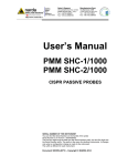
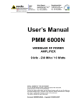
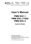
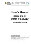
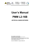
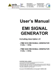
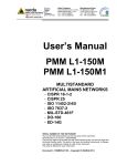
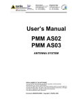
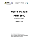
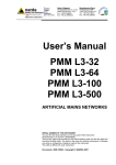
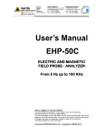
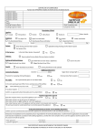
NARDA Safety Test Solutions S.r.l. Socio Unico Sales & Support: Via Leonardo da Vinci, 21/23 20090 Segrate (MI) - ITALY Tel.: +39 02 2699871 Fax: +39 02 26998700 Manufacturing Plant: Via Benessea, 29/B 17035 Cisano sul Neva (SV) Tel.: +39 0182 58641 Fax: +39 0182 586400 http://www.narda-sts.it User’s Manual PMM DR-01 DOUBLE RIDGED ANTENNA SERIAL NUMBER OF THE INSTRUMENT You can find the Serial Number on the Flared horn. Serial Number is in the form: 0000X00000. The first four digits and the letter are the Serial Number prefix, the last five digits are the Serial Number suffix. The prefix is the same for identical instruments, it changes only when a configuration change is made to the instrument. The suffix is different for each instrument. Document DR01EN-40103 - Copyright NARDA 2014 NOTE: If the instrument is used in any other way than as described in this Users Manual, it may become unsafe Before using this product, the related documentation must be read with great care and fully understood to familiarize with all the safety prescriptions. To ensure the correct use and the maximum safety level, the User shall know all the instructions and recommendations contained in this document. This product has a Pollution Degree II normally only non-conductive pollution occurs. Occasionally, however, a temporary conductivity caused by condensation must be expected. The information contained in this document is subject to change without notice. KEY TO THE ELECTRIC AND SAFETY SYMBOLS: You now own a high-quality instrument that will give you many years of reliable service. Nevertheless, even this product will eventually become obsolete. When that time comes, please remember that electronic equipment must be disposed of in accordance with local regulations. This product conforms to the WEEE Directive of the European Union (2002/96/EC) and belongs to Category 9 (Monitoring and Control Instruments). You can return the instrument to us free of charge for proper environment friendly disposal. You can obtain further information from your local Narda Sales Partner or by visiting our website at www.narda-sts.it . Warning, danger of electric shock Earth Read carefully the Operating Manual and its instructions, pay attention to the safety symbols. Unit Earth Connection Earth Protection Equipotential KEY TO THE SYMBOLS USED IN THIS DOCUMENT: The DANGER sign draws attention to a potential risk to a person’s safety. DANGER All the precautions must be fully understood and applied before proceeding. WARNING The WARNING sign draws attention to a potential risk of damage to the apparatus or loss of data. All the precautions must be fully understood and applied before proceeding. CAUTION The CAUTION sign draws attention against unsafe practices for the apparatus functionality. NOTE: II The NOTE draw attention to important information. Note and symbols Contents 1 General information 1.1 Introduction................................…............................… 1.2 Documentation….......................................................... 1.3 PMM DR-01 Double ridged Antenna…………………… 1.4 Standard accessories.…………………………………… 1.5 Optional accessories………………………………......... Page 1-1 1-1 1-1 1-2 1-2 2 Mounting Instructions 2.1 Introduction………………………………………………… 2.2 Initial inspection…………………………………………… 2.3 Environment……………………………………………….. 2.4 Return for service…...................................................... 2.5 Equipment cleaning……………………………………..… 2.6 PMM DR-01…………………......................................... 2.6.1 PMM DR-01 with PMM 9180..................................... 2.6.2 PMM DR-01 with other Receiver……………………… Page 2-1 2-1 2-1 2-1 2-1 2-1 2-2 2-4 3 Radiated Emission testing 3.1 Radiated Emission testing........................................ 3.1.1 The receiving antenna…………………………………. 3.1.2 The meter receiver…………………………………….. 3.2 Environmental EMF………………………………………. Page 3-1 3-1 3-1 3-2 Contents III Figures Figure 1-1 1-2 1-3 1-4 2-1 2-2 3-1 3-2 3-3 3-4 Page PMM DR-01 with PMM 9180….…………………………………………. PMM DR-01 with Antenna holder on the TR-01……………………….. DR-01 Typical Antenna factor………………………...…………………. DR-01 Typical VSWR…………………………………………………….. PMM DR-01 with PMM 9180……………………………………………... PMM DR-01 on the TR-01………………………………………………... PMM DR-01 Vertically polarized with PMM 9180……………………… PMM DR-01 Vertically polarized with Antenna support………………. PMM DR-01 Horizontally polarized with PMM 9180…………………… PMM DR-01 Horizontally polarized with Antenna support……………. 1-1 1-1 1-3 1-3 2-3 2-4 3-2 3-2 3-2 3-2 Tables Table 1-1 Page PMM DR-01 Double ridged Antenna Specifications........................... IV Contents 1-2 1 – General Information 1.1 Introduction This manual is a guide to the installation and use of the PMM DR-01 Double ridged Antenna. 1.2 Documentation Enclosed with this manual are: • service questionnaire to send back to NARDA if service is required. • check list of the supplied accessories 1.3 PMM DR-01 Double ridged Antenna The model DR-01 is a broadband double ridged horn antenna operating in the frequency range of 6 GHz - 18 GHz. The PMM DR-01 is designed for direct connection - without cable or adapters to the 18 GHz receivers PMM 9180. The DR-01 can be connected to any other RF equipment: small size with high manufacturing and calibration standards make it perfectly suitable for portable applications and in anechoic chambers. Each unit is individually calibrated before shipment; the test data are supplied with the antenna. The tripod PMM TR01 is recommended; the tripod stand is made by hard wood assuring the stability needed for holding antenna and receiver PMM 9180; the adjustable joint allows for easy antenna mounting and polarization changing. Fig. 1-1 PMM DR-01 with PMM 9180 The antenna N-m connector directly matches the 9180 RF input connector. A dedicated PVC Antenna support provided as a standard accessory can be used with the TR-01 to connect the DR-01 to any other Receiver; the standard ¼” threaded insert, located at the bottom of the Antenna holder allows mounting it on the tripod. Fig. 1-2 PMM DR-01 with Antenna holder Document DR01EN-40103 - NARDA 2014 General information 1-1 1.4 Standard Accessories The PMM DR-01 Double ridged Antenna includes the following: • Carrying Case 170/30N; • Antenna Support kit; • Antenna Certificate; • Return for Repair Form; • Operating Manual. 1.5 Optional Accessories The following accessories can be ordered separately: • Nf to Nf adapter; TABLE 1-1 PMM DR-01 Double ridged Antenna Specifications Frequency range 6 – 18 GHz Gain 9 – 16 dBi Antenna factor 36 – 41 dB/m VSWR < 2 (1.8 typ) Beam Width 3dB Eplane 33° - Hplane 38° @ 12GHz Max input power 150 W Connector N-male 50Ω Dimensions LxHxP 55 x 44 x 137 mm Weight 250 g Color RAL 7035 1-2 General information Fig. 1-3 DR-01 Typical antenna factor Fig. 1-4 DR-01 Typical VSWR General information 1-3 This page has been left blank intentionally 1-4 General information 2 – Mounting Instructions 2.1 Introduction This section provides the information needed to install and use your PMM DR-01 Double ridged Antenna. Included are information pertinent to initial inspection, interconnection, environment, mechanical mounting, cleaning, storage and shipment. 2.2 Initial inspection Inspect the shipping container for damage. If the shipping container or cushion material is damaged, it should be kept until the contents of the shipment have been checked for completeness and the antennas have been checked mechanically and electrically. Verify the accessories availability in the shipping referring to the accessories check list enclosed. Notify any damage to the carrier personnel as well as the NARDA Representative. 2.3 Environment The PMM DR-01 Double ridged Antenna is constructed of lightweight corrosion-resistant aluminum providing years of indoor and outdoor service. 2.4 Return for service If the PMM DR-01 Double ridged Antenna should be returned to NARDA for service, please complete the service questionnaire enclosed with the Users Manual and attach it to the instrument. To minimize the repair time, be as specific as possible when describing the failure. If possible, reuse of the original packaging to ship the equipment is preferable. In case other package should be used, ensure to wrap the instrument in heavy paper or plastic. Use a strong shipping container and use enough shock absorbing material around all sides of the equipment to provide a firm cushion and prevent movement in the container. Seal the shipping container securely. Mark the shipping container FRAGILE to encourage careful handling. 2.5 Equipment cleaning Use a clean, dry, non abrasive cloth for equipment cleaning. To clean the wooden tripod do not use any solvent, thinner, turpentine, acid, acetone or similar matter to avoid damage to it. 2.6 PMM DR-01 The PMM DR-01 combines small size with high manufacturing and calibration standards, making it perfectly suitable for portable applications and in anechoic chambers, particularly when used in conjunction with the EMI Receiver unit PMM 9180. The waveguide and the flared horn elements are made of aluminium and painted; a input N male connector is fixed to the waveguide. Document DR01EN-40103 - NARDA 2014 Mounting Instruction 2-1 2.6.1 PMM DR-01 with PMM 9180 To perfectly match the antenna to PMM 9180, a PVC Antenna Holder is provided as a PMM 9180 standard accessory; it balances the receiver and antenna weight when attached to a tripod or antenna mast. The Antenna Holder is supplied with all parts (screws, nuts, washers, wrench) required for assembling it as shown in the following pictures: Mounting the Tripod joint Mounting the Antenna Holder on PMM 9180 2-2 Mounting Instruction Fixing onto the Tripod. Attaching PMM DR-01 Double ridged Antenna. Change the PMM 9180 polarization from horizontal to vertical or vice versa and tighten the knob completely. Fig. 2-1 PMM DR-01 with PMM 9180 For further information on configuration and operation with PMM 9180, please refer to the operation manual supplied with it. Mounting Instruction 2-3 To use the PMM DR-01 with any other Receiver, a PVC Antenna Holder is 2.6.2 PMM DR-01 with Antenna holder provided as a standard accessory. The Antenna support kit is supplied with all parts (screws, washers and wrench) required for assembling it as shown in the following pictures. Mounting the Antenna holder without screwing it completely. Fixing the PMM DR-01 onto the Antenna holder and tighten it completely. The standard ¼” threaded insert, located at the bottom of the Antenna holder allows mounting it on the TR-01. Fig. 2-2 PMM DR-01 with Antenna holder on the TR-01 Change the PMM DR-01 polarization from horizontal to vertical or vice versa without loosing the Antenna holder completely. 2-4 Mounting Instruction 3 - Radiated Emission testing 3.1 Radiated Emission testing According to the international Standards, the purpose of this test is to verify that the EUT's radiated electromagnetic emissions are below specified limits during operation. The receiving antenna can be located either at 3 or 10 meter from the EUT and must scan from 1 to 4 meters in height to locate the EUT's worst emission level. A typical emissions test system set-up is composed of: • Receiving antenna; • Meter receiver. 3.1.1 The receiving Antenna The antenna parameter relating the incident E-Field to the voltage output of the antenna is the Antenna Factor usually provided by the manufacturer in dB/m. A combination of two or more antennas is used to cover the wide frequency range required by the Standard, from 30 MHz up. - PMM BC-01 Biconical dipole 30 to 200 MHz; - PMM LP-02 Log periodic 200 MHz to 3 GHz; - PMM LP-03 Log periodic 800 MHz to 6 GHz; - DR-01 Double ridged Antenna 6 GHz to 18 GHz. 3.1.2 The meter receiver The meter receiver is typically either a radio receiver or a spectrum analyzer. The calculation of the measured E-field signal level is given by: 1 µV E dB = S (dBµV ) + C1 (dB ) − PA(dB ) + C2 (dB ) + AF dB m m where: µV E dB = Corresponding Electric field m S (dBµV ) = Measured signal strength C1 (dB ) = Preamplifier interconnecting cable PA(dB ) = Preamplifier gain C2 (dB ) = Interconnecting cable loss 1 AF dB = Antenna factor m Document DR01EN-40103 - NARDA 2014 Radiated Emission and Immunity testing 3-1 Fig. 3-1 Radiated emission test setup – PMM DR-01 Vertically polarized with PMM 9180 Fig. 3-2 Radiated emission test setup – PMM DR-01 Horizontally polarized with Antenna support Fig. 3-3 Radiated emission test setup – PMM DR-01 Horizontally polarized with PMM 9180 Fig. 3-4 Radiated emission test setup – PMM DR-01 Horizontally polarized with Antenna support 3.2 Environmental EMF 3-2 The PMM DR-01 Double ridged Antenna can also be used in environmental EMF applications for narrow band EMF exposure assessment. The wide frequency range and low VSWR allow for accurate tests with linear polarization, in conjunction with receiver/spectrum analyzer of adequate performances. Radiated Emission and Immunity testing NARDA Safety Test Solutions S.r.l. Socio Unico Sales & Support: Via Leonardo da Vinci, 21/23 20090 Segrate (MI) - ITALY Tel.: +39 02 2699871 Fax: +39 02 26998700 Manufacturing Plant: Via Benessea, 29/B 17035 Cisano sul Neva (SV) Tel.: +39 0182 58641 Fax: +39 0182 586400 http://www.narda-sts.it Mod. 18-1 Caro cliente grazie per aver acquistato un prodotto NARDA! Sei in possesso di uno strumento che per molti anni ti garantirà un’alta qualità di servizio. NARDA riconosce l'importanza del Cliente come ragione di esistenza; ciascun commento e suggerimento, sottoposto all'attenzione della nostra organizzazione, è tenuto in grande considerazione. La nostra qualità è alla ricerca del miglioramento continuo. Se uno dei Suoi strumenti NARDA necessita di riparazione o calibrazione, può aiutarci a servirla più efficacemente compilando questa scheda e accludendola all’apparecchio. Tuttavia, anche questo prodotto diventerà obsoleto. In questo caso, ti ricordiamo che lo smaltimento dell'apparecchiatura deve essere fatto in conformità con i regolamenti locali. Questo prodotto è conforme alle direttive WEEE dell’Unione Europea (2002/96/EC) ed appartiene alla categoria 9 (strumenti di controllo). Lo smaltimento, in un ambiente adeguato, può avvenire anche attraverso la restituzione del prodotto alla NARDA senza sostenere alcuna spesa. Può ottenere ulteriori informazioni contattando i venditori NARDA o visitando il nostro sito Web www.narda-sts.it. Dear Customer thank you for purchasing a NARDA product! You now own a high-quality instrument that will give you many years of reliable service. NARDA recognizes the importance of the Customer as reason of existence; in this view, any comment and suggestion you would like to submit to the attention of our service organization is kept in great consideration. Moreover, we are continuously improving our quality, but we know this is a never ending process. We would be glad if our present efforts are pleasing you. Should one of your pieces of NARDA equipment need servicing you can help us serve you more effectively filling out this card and enclosing it with the product. Nevertheless, even this product will eventually become obsolete. When that time comes, please remember that electronic equipment must be disposed of in accordance with local regulations. This product conforms to the WEEE Directive of the European Union (2002/96/EC) and belongs to Category 9 (Monitoring and Control Instruments). You can return the instrument to us free of charge for proper environment friendly disposal. You can obtain further information from your local NARDA Sales Partner or by visiting our website at www.narda-sts.it. Servizio richiesto: Service needed: Solo taratura Calibration only Riparazione Repair Riparazione & Taratura Repair & Calibration Taratura SIT Certified Calibration Altro: Other: Ditta: Company: Indirizzo: Address: Persona da contattare: Technical contact person: Telefono: Phone n. Modello: Equipment model: Numero di serie: Serial n. Accessori ritornati con l’apparecchiatura: Nessuno Cavo(i) Cavo di alimentazione Accessories returned with unit: None Cable(s) Power cable Altro: Other: Sintomi o problemi osservati: Observed symptoms / problems: Guasto: Fisso Intermittente Failure: Continuous Intermittent Sensibile a : Freddo Sensitive to: Cold Caldo Heat Descrizione del guasto/condizioni di funzionamento: Failure symptoms/special control settings description: Se l’unità è parte di un sistema descriverne la configurazione: If unit is part of system please list other interconnected equipment and system set up: Vibrazioni Altro Vibration Other Suggerimenti / Commenti / Note: Suggestions / Comments / Note: