1
SPECTRACAL, INC.
VideoForge 4K
Video Pattern Generator
User Manual
VideoForge 4K
Video Pattern Generator
User Manual
Software Version 65
April, 2013
SpectraCal, Inc.
3528 Bagley Ave. N.
Seattle, WA 98103
USA
206-420-7514
1
T A B L E
O F
C O N T E N T S
Table of Contents
VideoForge 4K Features ..................................................................................................................4
Included Items ......................................................................................................................................6
VideoForge 4K Front Panel ............................................................................................................6
Front Panel USB Ports .......................................................................................................................6
Power Up, Power Down ...................................................................................................................7
VideoForge 4K Back Panel ..............................................................................................................7
Video Signal Output Connections................................................................................................7
Generator Control Connection......................................................................................................8
VideoForge 4K to HDMI/DVI television, projector, or display.......................8
VideoForge 4K to Host Computer .................................................................................8
VideoForge 4K Boot Sequence........................................................................................9
VideoForge Manual Control ...........................................................................................................9
Generator Output ............................................................................................................................. 10
Video Format......................................................................................................................... 10
Output Titling........................................................................................................................ 12
Colorspace/Bit Depth ....................................................................................................... 12
Color Encoding ..................................................................................................................... 12
Video Mute ............................................................................................................................. 12
Video Calibration .............................................................................................................................. 13
Test Patterns ....................................................................................................................................... 14
Patterns Rendering Modules ........................................................................................ 14
Pattern Aliases...................................................................................................................... 15
Custom Test Patterns........................................................................................................ 15
Administration................................................................................................................................... 17
Network Settings................................................................................................................. 17
Updating Software.............................................................................................................. 17
Resetting the VideoForge ............................................................................................... 18
Pattern Rendering Modules ........................................................................................................ 18
Brightness ............................................................................................................................... 20
Checkerboard........................................................................................................................ 21
Chromaticity .......................................................................................................................... 23
Color .......................................................................................................................................... 24
2
T A B L E
O F
C O N T E N T S
Colorbars ................................................................................................................................. 24
Contrast.................................................................................................................................... 25
Geometry................................................................................................................................. 27
Gradient ................................................................................................................................... 27
ImageFile ................................................................................................................................. 29
Resolution............................................................................................................................... 31
SectorStar................................................................................................................................ 32
Sharpness................................................................................................................................ 33
Sine ............................................................................................................................................. 34
VerticalBar.............................................................................................................................. 35
Window.................................................................................................................................... 36
ZonePlate ................................................................................................................................ 37
XML-RPC Interface........................................................................................................................... 39
Index........................................................................................................................................................ 39
3
V I D E O F O R G E
O V E R V I E W
Chapter
1
VideoForge Overview
C
ongratulations on your purchase of the SpectraCal VideoForge 4K Digital Video Generator.
We have designed the VideoForge to be an affordable, feature-rich test pattern generator.
The VideoForge outputs all current 4K formats via Quad-Link SDI, and also supports lowerresolution patterns via Dual-Link SDI, Single-Link SDI, HDMI, and DVI.
This highly flexible platform generates thousands of reference pattern variations with its 16 software
pattern renderers, for testing, and calibrating video displays. The VideoForge produces any one of
the billion possible colors inside a display’s 3D color space, making the VideoForge better suited than
any previous solution for display characterization generating a 3D Cube LUT. While many pattern
generators are designed for use in a design and engineering role, we designed the VideoForge for
field applications, but also included many features that have previously been available only in labgrade generators.
VideoForge 4K Features
SDI 4K, Quad HD, 2K, HD, and SD video formats, in YCbCr or RGB color space, at 8 or 10
bits/color.
HDMI v1.4a 2K, HD, and SD video formats, in YCbCr or RGB color space, at 8 or 10 bits/color.
Flexible generator output controls for video resolution, frame rate, color space, color bit
depth, color encoding, and color gating.
All standard performance test and calibration patterns, with thousands of pattern variations
from sixteen versatile test pattern renderers, plus easy updates for future needs.
Custom image and test pattern support for individual user needs.
Supports 3D color cube LUT calibration, with full triplet output of any RGB color value.
Convenient manual unit control, with browser-based control and no software installation.
Fully integrated with SpectraCal CalMAN Display Calibration Software.
4K SDI Video Format (Quad Link 1.5 Gb/s SDI):
o 4x2048x1080p 23.98/24/25 (4096x2160p)
4K SDI Video Format (Dual Link 3 Gb/s SDI):
o 4x2048x1080p 23.98/24/25 (4096x2160p)
Quad HD SDI Video Format (Quad Link 1.5 Gb/s SDI):
o 4x1920x1080p 23.98/24/25 (3840x2160p)
2K SDI Video Format (Dual Link 3 Gb/s SDI):
4
V I D E O F O R G E
O V E R V I E W
o 2048x1080p 23.98/24/25 (digital cinema)
HD SDI Video Format (Single Link 3 Gb/s SDI):
o 1080p 50/59.94/60 (3Ga format & 3Gb format)
HD SDI Video Format (Dual Link 1.5 Gb/s SDI):
o 1080p 50/59.94/60
HD SDI Video Formats (Single Link 1.5 Gb/s SDI):
o 1080p 23.98/24/25/29.97/30
o 1080i 50/59.94/60
o 720p 50/59.94/60
SD SDI Video Formats (Single Link 270 Mb/s SDI):
o 625i 50 PAL (576i)
o 525i 59.94 NTSC (480i)
HDMI/DVI Video Formats: (4:4:4 RGB or 4:2:2 YCrCb, 8 or 10 bits/color)
o 2048x1080p 23.98/24/25 (digital cinema)
o 1080p 23.98/24/25/29.97/30/50/59.94/60
o 1080i 50/59.94/60
o 720p 50/59.94/60
o 625i 50 PAL (576i)
o 525i 59.94 NTSC (480i)
Sixteen test pattern renderers provide standard performance test and calibration patterns,
with thousands of pattern variations:
o Brightness
o Checkerboard
o Chromaticity
o Color
o ColorBars
o Contrast
o Geometry
o Gradient
o ImageFile (custom .png and .jpg images loaded from USB drive)
o Resolution
o SectorStar
o Sharpness
o Sine
o VerticalBar
o Window
o ZonePlate
5
V I D E O F O R G E
O V E R V I E W
Dimensions
Shipping: 12” x 12” x 5”
Unit: 9.5” x 8” x 3”
Included Items
Power Supply; 12vdc 5a, all region 100-220vac
USB Wi-Fi wireless adapter (to be supported in subsequent unit software)
USB flash drive
HDMI to mini HDMI audio/video output cable
4 BNC to 4 mini-connector (1.0/2.3) SDI video output cable assembly
VideoForge 4K Front Panel
Front Panel USB Ports
Inside the left front access door are two USB ports. The left USB
port contains the supplied USB Wi-Fi wireless adapter. The
wireless adapter should be left in the left side USB port. The
wireless adapter is not supported in the original release software,
but will be supported as a control interface in subsequent software.
The right USB port inside the front access door contains the supplied USB flash drive. The drive
contains some example custom images and a pdf copy of this quick start guide.
Note: Wi-Fi interface control, RS-232 interface control, and front panel menu control will be supported
in subsequent software.
6
V I D E O F O R G E
O V E R V I E W
Power Up
The power control button for the VideoForge is located in the upper right corner of the front panel.
To power up the unit, momentarily press the Power button and release.
On power up, if the VideoForge is connected to a network, the front panel LCD shows; Booting,
Booting .., Booting …, and then switches to show the unit’s network host name and IP address. If the
VideoForge is not connected to a network, or does not get an IP address from a DHCP server, the
front panel LCD will continue to show “Booting ….”
Once the connected VideoForge is connected to an active DHCP network, power cycle the unit to
obtain an IP address.
On power up, the VideoForge defaults to a 720p60 YCC-10 Rec709 format, with the AV Foundry logo
image, with outputs on SDI 3, SDI 4, and HDMI.
Power Down
To power down the unit, momentarily press the Power button and release. After approximately
three seconds, the unit then powers down.
VideoForge 4K Back Panel
Video Signal Output Connections
Four SDI output mini-connectors are provided for SDI formats. For single-link SDI, a single, mirrored
output is provided on both the SDI 3 and SDI 4 connectors. For dual-link SDI, the dual output is
provided on the SDI 3 and SDI 4 connectors. For Quad HD or 4K SDI, all four of the mini-connectors
are used as outputs, one for each of the 4K play out quadrants. A cable assembly with four mini7
V I D E O F O R G E
O V E R V I E W
connectors on one end and four BNCs on the other end is provided for connecting equipment to the
SDI outputs.
One mini HDMI 1.4a connection is provided for SD, HD, and 2K video formats for either HDMI or DVI
devices.
VideoForge to SDI monitor or projector
Connect the VideoForge to an SDI monitor or SDI projector using the supplied mini BNC to BNC cable
assembly.
Note: When the VideoForge is producing a single link SDI format, it mirrors the output to both the SDI 3
and the SDI 4 output connectors. Connect either of the single link SDI outputs to the target display. If
you connect both single link outputs to a display, the display may attempt to display the signal as a dual
link SDI format, rather than as a single link SDI format.
VideoForge to HDMI/DVI monitor or projector
Connect the VideoForge to an HDMI monitor or HDMI projector using the supplied mini HDMI to
HDMI cable.
Generator Control Connection
Connect the VideoForge to a host computer via connections to a common network. Connect the
VideoForge LAN port to a network port, using an Ethernet cable (either straight-through or
crossover).
Control Interfaces
The VideoForge features two control interfaces for controlling the generator output:
Manual User Control – The VideoForge generator provides an IP-based control
application for convenient manual control. The Manual User Control interface is
documented in Chapter 2 of this manual, beginning on page 9.
Automated Computer Control – The VideoForge generator provides an XML-RPC interface
for program control. The XML-RPC interface is documented in Chapter 4 of this manual, on
page 39.
CalMAN supports the VideoForge XML-RPC interface to totally control the generator within
the CalMAN program. In CalMAN, when you select the AV Foundry VideoForge II generator
on the Source Settings tab, you then supply the generator’s IP address and click Connect.
Note: Wi-Fi interface control, RS-232 interface control, and front panel menu control will be supported
in subsequent VideoForge software.
8
M A N U A L
U S E R
C O N T R O L
Chapter
2
VideoForge Manual User Control
T
he VideoForge generator provides an IP-based control application for convenient manual
control. This control interface is accessed by opening a web browser and navigating to the
VideoForge IP address, shown on the generator LCD display. Adobe Flash Player, version 10
or later, must be installed to use the VideoForge manual control application.
Manual Control
To manually control the VideoForge:
1. Connect the VideoForge to a network router with an Ethernet cable, power on the
VideoForge, and note the unit’s IP address on the LCD.
2. Open a web browser (e.g. Internet Explorer, Safari, Firefox, etc.).
3. Enter the unit’s IP address into the browser’s address bar and press Enter.
4. Select the desired VideoForge user interface page and make desired selections.
When the user control application initially opens, it displays the Output page.
9
M A N U A L
U S E R
C O N T R O L
Generator Output
The Output page gives the user full control over the VideoForge SDI and HDMI/DVI output signals.
The available output option controls are:
1.
2.
3.
4.
5.
6.
Video Format
Output Titling
Color Gating
Color space/Bit Depth
Color Encoding
Video Mute
Video Format
The VideoForge 4K provides a number of common pre-defined SDI and HDMI/DVI video formats, as
documented in the following table:
10
M A N U A L
U S E R
C O N T R O L
VideoForge 4K - Supported Formats
Format
525 59.94 (480i)
625 50.00 (576i)
720p 50.00
720p 59.95
720p 60.00
1080i 50.00
1080i 59.95
1080i 60.00
1080p 23.98
1080p 24.00
1080p 25.00
1080p 29.97
1080p 30.00
1080p 50.00 DL
1080p 59.95 DL
1080p 60.00 DL
1080p 50.00 3Ga
1080p 59.95 3Ga
1080p 60.00 3Ga
1080p 50.00 3Gb
1080p 59.95 3Gb
1080p 60.00 3Gb
1080p2k 23.98
1080p2k 24.00
1080p2k 25.00
4x1920x1080p 23.98
4x1920x1080p 24.00
4x1920x1080p 25.00
4x2048x1080p 23.98
4x2048x1080p 24.00
4x2048x1080p 25.00
YCC8
X
X
X
X
X
X
X
X
X
X
X
X
X
X
X
X
X
X
X
X
X
X
X
X
X
X
X
X
X
X
X
YCC10
X
X
X
X
X
X
X
X
X
X
X
X
X
X
X
X
X
X
X
X
X
X
X
X
X
X
X
X
X
X
X
RGB8
RGB10
X
X
X
X
X
X
X
X
X
X
X
X
X
X
X
X
X
X
X
X
X
X
X
X
X
X
X
X
X
X
X
X
X
X
X
X
X
X
X
X
X
X
X
X
X
X
X
X
X
X
X
X
SLSDI
X
X
X
X
X
X
X
X
X
X
X
X
X
DLSDI
3GaSDI
QLSDI
HDMI/
DVI
X
X
X
X
X
X
X
X
X
X
X
X
X
X
X
X
X
X
X
X
X
X
X
X
X
X
X
X
X
X
X
YCC-8 / YCC-10: YCrCb, 4:2:2, 8 or 10 bits/color
RGB-8 / RGB-10: RGB, 4:4:4, 8 or 10 bits/color
SL-SDI: Single link SDI (mirrored outputs on SDI 3 & SDI 4)
DL-SDI: Dual link SDI (output on SDI 3 / SDI 4)
3Ga-SDI: Single link 3 Gb/s SDI, 3Ga standard (mirrored outputs on SDI 3 & SDI 4)
3Gb-SDI: Single link 3 Gb/s SDI, 3 Gb standard (mirrored outputs on SDI 3 & SDI 4)
QL-SDI: Quad link 3 Gb/s SDI (SDI 1 = UL, SDI 2 = UR, SDI 3 = LL, SDI 4 = LR)
11
3GbSDI
X
X
X
X
X
X
X
X
X
M A N U A L
U S E R
C O N T R O L
Output Titling
Output Titling allows the user to select which information (if any) is displayed on-screen with the
pattern. The options are None, Name, and Version.
Title
None (default)
Name
Version
Description
No pattern titles are displayed.
The pattern name and video format is
displayed in the upper left hand screen
corner.
Pattern renderer version information
is also displayed.
Color Gating
The color gating options allow the user to force the Red, Green, or Blue output components to
specific values.
Color space/Bit Depth
The Color space option allows the user to select the color space and bit depth for output. The
available selections are RGB 8-bit, RGB 10-bit, YCC 8-bit, and YCC 10-bit.
Color Encoding
The Color Encoding option allows the user to select the color space and bit depth for output. The
available selections are Rec601 and Rec709.
Video Mute
The VideoMute option “silences” the generator when checked, blanking the video output.
12
M A N U A L
U S E R
C O N T R O L
Video Calibration
The Video Cal page provides a shortcut to ten test patterns that are very useful for video calibration
procedures. When a pattern is selected, by clicking a pattern button on the left side of the page,
parameter option controls for the selected pattern are then available to the right of the pattern
buttons.
13
M A N U A L
U S E R
C O N T R O L
Test Patterns
The Patterns page provides selection and full control of all pattern rendering modules and pattern
aliases installed on the VideoForge. Select the desired pattern to display from the Pattern drop down
list. Pattern rendering modules can be recognized by the parameter option controls that are
provided below the Pattern drop down list. Use the parameter option controls to modify various
characteristics of the output test pattern.
Pattern Rendering Modules
The VideoForge Patterns page provides access to 16 pattern rendering modules, listed below, which
can be selected from the Pattern drop down list. When one of these 16 rendering modules is
selected, the current test pattern configuration is sent to the VideoForge video outputs. Pattern
parameter controls are provided for each pattern rendering module, below the Pattern drop down,
to change the current test pattern configuration. Details for each pattern rendering module is
provided in Chapter 3 of this manual, beginning on page 18.
Brightness
Checkerboard
Chromaticity
Color
Colorbars
Contrast
Geometry
Gradient
ImageFile
Resolution
SectorStar
Sharpness
14
Sine
VerticalBar
Window
ZonePlate
M A N U A L
U S E R
C O N T R O L
Pattern Aliases
In addition to the pattern rendering modules, the VideoForge also provides a number of pattern
aliases in the Pattern drop down list. A pattern alias is a static test pattern with a pre-defined set of
parameters. When a pattern alias is selected from the Pattern drop-down, there are no parameter
option controls provided.
Custom Test Patterns (Image Files)
In addition to its built-in patterns, the VideoForge also renders custom test patterns or image files
stored on a USB flash drive. The USB flash drive supplied with the VideoForge contains a number of
sample 4K images.
Custom image files should be named as: {basename}{-vres}.{ext} (e.g. testpattern1-1080.jpg).
{basename} can be anything
{-vres} optional - specifies the vertical resolution of the file image (no leading zeros)
{ext} is either "png" or "jpg.”
When a USB flash drive is connected, the VideoForge searches the drive folders for any .png or .jpg
files. These image files are then listed in the Pattern drop down as "{drive name}/{basename}.” If
there is just one version of the file with the selected basename, the file is just loaded. If there are
multiple versions of the file with the selected basename, with different vertical resolutions indicated,
VideoForge looks for a resolution equal to or smaller than the currently selected resolution. If there
are no file resolutions equal to or smaller than the currently selected resolution, the smallest file
resolution is selected.
If both "png" and "jpg” versions of a file are present, the VideoForge selects the "png" file.
To display custom test patterns or images with the VideoForge:
1. Save custom test pattern or image files to a USB flash drive, in PNG or JPEG format, at the
desired display resolution (e.g. 1920x1080).
2. Connect the flash drive to a VideoForge USB port.
3. Access the VideoForge control interface, as outlined in the “Manual User Control” section of
this manual, on page 9.
4. On the Patterns tab in the VideoForge control interface, open the Pattern drop down box. Any
custom files available on an attached USB drive will be listed, grouped by USB drive.
5. Select one of the custom file names to display the custom image.
15
M A N U A L
U S E R
C O N T R O L
Sample 4K Images
(All images provided at both 3840x2160 and 4096x2160 resolution on supplied USB flash drive.)
Resolution pattern:
•
•
•
•
•
Brightness/Contrast Sweeps with both Video and PC Background Levels
Sharpness/resolution lines 1 pixel, 2 pixel and 4 pixel widths (Vertical and Horizontal, light
on dark and inverted)
Grayscale smooth sweep and Gamut Smooth sweeps
Overscan 0 Yellow 95%, 90% and 85% marked in green
Marked Center Point
Visual Assessment images:
• Gum Wall (detail and color assessment)
• Ice (white detail assessment)
• Lights (full saturation color assessment)
• Locks (detail assessment)
• Peafowl (full saturation colors and detail assessment)
• Seafood (color and detail assessment)
• Skyline (dark levels assessment)
• Sporting (detail and full saturation colors)
16
M A N U A L
U S E R
C O N T R O L
Administration
The Admin page provides version and serial number information for the VideoForge generator. It
also allows a user to configure the network settings, update the VideoForge software, and reset the
generator.
Generator Settings
The VideoForge output signal levels can be changed to one of three different selections:
Digital Levels [0-255, 4-1019]
SMPTE Legal Levels [0%-109%]
Full Range Levels [0%-100%]
Network Settings
The VideoForge network settings are displayed as read only fields on the Admin Page. The following
network settings are displayed:
1. Hostname – The network node name of the VideoForge generator.
2. Subnet – The network address used by the VideoForge and the host computer for
communication.
3. VideoForge Address – The VideoForge IP address.
17
M A N U A L
U S E R
C O N T R O L
Network Operation
When the VideoForge is powered up or connected to a host DHCP computer, it makes a request on
this network interface for an IP address. The assigned IP address is shown on the VideoForge Admin
page and on the VideoForge front panel LCD display.
Updating VideoForge Software
Updating the software modules on the VideoForge is accomplished through the Firmware Update
button on the Admin page. The updates are all done in a three step process: 1) Select the software
update file, 2) Upload the file, and 3) Install the file. As each step is completed, the button’s function
changes to the next step. You can cancel the operation at any point by navigating away from the
Admin page.
Resetting the VideoForge
The VideoForge 4K can be reset at three different levels:
Software Reset
Soft Reboot
Hard Reboot
The Software Reset closes and re-starts the VideoForge internal software without re-booting the
entire system. The software reset should be the first order of troubleshooting, as it can fix problems
more quickly than either a soft reboot or a hard reboot.
Click the Software Reset button on the Admin Page to perform a Software Reset.
Click the Reboot button in the Admin Page to perform a Soft Reboot on the unit. This may be
advised if Software Reset is ineffective at solving a problem, or for certain types of software
updates.
To Hard Reboot the VideoForge, cycle the power to fully reset the unit. Pressing the Power
button for an extended period forces the VideoForge to power down and reset.
18
P A T T E R N
R E N D E R I N G
M O D U L E S
Chapter
3
Pattern Rendering Modules
T
he VideoForge 4K is unique among video pattern generators, in that it has been designed
with extremely versatile pattern rendering modules. Each pattern renderer provides a
selection of pattern parameters that allows a user to customize the test pattern produced by
the rendering module. This chapter details each pattern rendering module and its parameter
options.
19
P A T T E R N
R E N D E R I N G
M O D U L E S
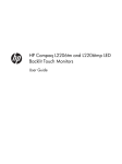
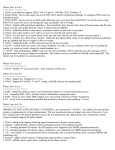
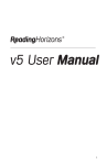
Brightness
The Brightness pattern is used to evaluate and calibrate the brightness or black level control on a
video display.
There is a single parameter option for this pattern:
Parameter
bgLevel
Description
Selects the pattern’s background color and level.
Brightness pattern parameter options
Brightness test pattern
20
P A T T E R N
R E N D E R I N G
M O D U L E S
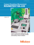
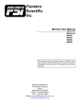
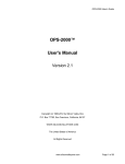
Checkerboard
The Checkerboard pattern displays a grid of two alternating colors. This pattern can be used to for a
variety of performance tests and calibrations. The traditional use of the checkerboard pattern is for
contrast ration measurements. The VideoForge Checkerboard pattern can be used to calibrate a
display’s Color control setting by setting loColor to blue (0, 0, 191), and hiColor to white (191, 191,
191). The checkerboard can also be used to calibrate a display’s Tint/Hue control by setting loColor
to cyan (0, 191, 191) and hiColor to magenta (191, 0, 191).
The pattern parameter options are:
Parameter
hPatch
vPatch
Invert
loColor
hiColor
Description
The number of horizontal color patch transitions.
The number of vertical color patch transitions
When set, the two colors are exchanged. This can be used, for example, to take contrast ratio measurements without repositioning a color sensor.
One of the two alternating colors to display.
The second of the two alternating colors.
Checkerboard pattern parameter options
21
P A T T E R N
R E N D E R I N G
M O D U L E S
Checkerboard test pattern examples
22
P A T T E R N
R E N D E R I N G
M O D U L E S
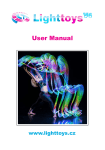
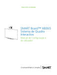
Chromaticity
The Chromaticity pattern displays a CIE 1931 chromaticity chart.
The pattern parameter options are:
Parameter
Style
RgbSpace
Gamma
Description
Selects whether the colors are Shaded, across the entire chart; Constrained to only the gamut triangle; or
Full Range, with no reference gamut triangle.
Selects the size and shape of the reference gamut triangle, defining the color space. The choices are:
Rec709 (high definition), Rec601 (standard definition).
Selects the target gamma.
Chromaticity pattern parameter options
Chromaticity test pattern
23
P A T T E R N
R E N D E R I N G
M O D U L E S
Color
The Color pattern displays a set of color bars.
There is a single parameter option for this pattern:
Parameter
Brightness
Description
Selects the color luminance levels.
Color pattern parameter options
Color test pattern
24
P A T T E R N
R E N D E R I N G
M O D U L E S
Colorbars
The Colorbars pattern displays a set of SMPTE color bars.
There is a single parameter option for this pattern:
Parameter
Brightness
Description
Selects the color luminance levels.
Colorbars pattern parameter options
Colorbars test pattern
25
P A T T E R N
R E N D E R I N G
M O D U L E S
Contrast
The Contrast pattern displays bright bars of grey, from 232 to 255, on a selectable background.
There is a single parameter option for this pattern:
Parameter
bgLevel
Description
Selects the pattern’s background color and level. If the Grey option box is unchecked, any color may be selected, by
specifying the desired color’s Red, Green, and Blue levels.
Contrast pattern parameter options
Contrast test pattern
26
P A T T E R N
R E N D E R I N G
M O D U L E S
Geometry
The Geometry pattern consists of straight lines and circles that allow the user to evaluate any
geometric distortions induced by the display system.
The pattern parameter options are:
Parameter
hLines
vLines
Description
Selects the number of horizontal lines displayed in the pattern.
Selects the number of vertical lines displayed in the pattern.
Geometry pattern parameter options
Geometry test pattern
27
P A T T E R N
R E N D E R I N G
M O D U L E S
Gradient
The Gradient pattern presents either a number of stepped bars or a smooth gradient.
The pattern parameter options are:
Parameter
Style
Orientation
Steps
Gamma
Mirror
Splits
StartColor
EndColor
Description
Selects Normal bars, RGBCMYK bars (RGBCMY luminance and saturation steps), RGBCMYK_lo bars
(RGBCMY luminance steps), or RGBCMYK_hi bars (RGBCMY saturation steps).
Selects either Vertical or Horizontal bars.
Selects the number of shading steps. Selecting 0 produces a smooth gradient.
Selects the gamma to be overlaid on the bar or gradient range.
Reverses the bar order on one half of the screen, when checked.
Selects the number of times the bars are split, with the level range reversed. Selecting 0 produces full
height or full width bars.
Selects the background color and level for the first bar. If the Grey option box is unchecked, any color may
be selected, by specifying the desired color’s Red, Green, and Blue levels.
Selects the background color and level for the last bar. If the Grey option box is unchecked, any color may
be selected, by specifying the desired color’s Red, Green, and Blue levels.
Gradient pattern parameter options
28
P A T T E R N
R E N D E R I N G
M O D U L E S
Gradient test pattern examples
29
P A T T E R N
R E N D E R I N G
M O D U L E S
ImageFile
The ImageFile pattern renderer page provides background administrative support for custom image
files that can be loaded from a connected USB flash drive. This page is not required for use by an end
user of the VideoForge generator.
30
P A T T E R N
R E N D E R I N G
M O D U L E S
Resolution
The Resolution pattern is used to check a display’s pixel resolution.
The pattern parameter options are:
Parameter
LowColor
HiColor
Description
Selects the background color and level for the low level bars. If the Grey option box is unchecked, any color
may be selected, by specifying the desired color’s Red, Green, and Blue levels.
Selects the background color and level for the high level bars. If the Grey option box is unchecked, any color
may be selected, by specifying the desired color’s Red, Green, and Blue levels.
Resolution pattern parameter options
Resolution Test Pattern
31
P A T T E R N
R E N D E R I N G
M O D U L E S
SectorStar
The pattern parameter options are:
Parameter
Style
Divisions
Color1
Color2
Description
Selects 2Color, RGBCMYK bars, or Sine.
Selects the total number of star segments
Selects the color and level for the odd alternating star segments. If the Grey option box is unchecked, any
color may be selected, by specifying the desired color’s Red, Green, and Blue levels.
Selects the color and level for the even alternating star segments. If the Grey option box is unchecked, any
color may be selected, by specifying the desired color’s Red, Green, and Blue levels.
SectorStar pattern parameter page
32
P A T T E R N
R E N D E R I N G
M O D U L E S
Sharpness
The Sharpness pattern is used to check for artifacts introduced by edge enhancement functions in the
display.
Sharpness pattern parameter page
Resolution Test Pattern
33
P A T T E R N
R E N D E R I N G
M O D U L E S
Sine
The Sine pattern is a multiburst pattern variant that provides alternating bars of decreasing width,
corresponding to a range of video signal frequencies. This pattern, however, provides a sinusoidal
transition between the alternating bars, rather than abrupt square edge transitions. This results in a
corresponding range of video signal frequencies that more closely relates to those in video
transmission systems for each selected signal resolution.
The pattern parameter options are:
Parameter
Scale
StartColor
EndColor
Description
Increases or decreases the range of multiburst bar widths. The default value of 10 sets the minimum bar
spacing equal to the standard line width of the selected signal resolution.
Selects the color and level for the odd alternating bars. If the Grey option box is unchecked, any color may
be selected, by specifying the desired color’s Red, Green, and Blue levels.
Selects the color and level for the even alternating bars. If the Grey option box is unchecked, any color may
be selected, by specifying the desired color’s Red, Green, and Blue levels.
Sine pattern parameter page
34
P A T T E R N
R E N D E R I N G
M O D U L E S
VerticalBar
The VerticalBar pattern provides either two color or multicolor alternating vertical bars.
The pattern parameter options are:
Parameter
style
width
offset
loColor
hiColor
Description
Either “2color” or “wrgbcmyk” multicolor can be selected.
Sets the number of pixels in a pair of bars. Larger numbers result in wider bars.
Offsets the pattern to the right by the selected number of pixels.
Selects the color and level for the odd alternating bars in “2color” mode. If the Grey option box is
unchecked, any color may be selected, by specifying the desired color’s Red, Green, and Blue levels.
Selects the color and level for the even alternating bars in “2color” mode. If the Grey option box is
unchecked, any color may be selected, by specifying the desired color’s Red, Green, and Blue levels.
VerticalBar pattern parameter page
35
P A T T E R N
R E N D E R I N G
M O D U L E S
Window
The Window pattern displays a window of a specified size and color, on a specified background color,
at a specified location on the screen.
The pattern parameter options are:
Parameter
Style
loPluge
hiPluge
Size
APL
xOffset
yOffset
gridLines
hDiv
vDiv
Color
BgColor
Description
Either Constant Size or Constant APL can be selected. For explanation, see the Size and APL parameters
below.
When selected, displays a set of loPluge bars to the left of the Constant Size window.
When selected, displays a set of hiPluge bars to the right of the Constant Size window.
The window size is specified as a percentage of the total screen area.
When Constant APL style is selected, the APL selection box sets the target APL (average picture level). With
Constant APL, the background level is adjusted to make the overall screen level average out to the selected
APL. This can be an advantage when calibrating a display that changes its performance characteristics with
changes of picture APL.
Changes the horizontal position of the window, with the default 50 value at the middle of the screen.
Changes the vertical position of the window, with the default 50 value at the middle of the screen.
When selected, vertical and horizontal grid lines are superimposed on the pattern.
Selects the number of horizontal grid line divisions.
Selects the number of vertical grid line divisions.
Selects the color and level for the pattern Window. If the Grey option box is unchecked, any color may be
selected, by specifying the desired color’s Red, Green, and Blue levels.
Selects the color and level for the pattern background. If the Grey option box is unchecked, any color may
be selected, by specifying the desired color’s Red, Green, and Blue levels.
Window pattern parameter page
36
P A T T E R N
R E N D E R I N G
M O D U L E S
Window Test Pattern examples
37
P A T T E R N
R E N D E R I N G
M O D U L E S
ZonePlate
The Zone Plate pattern creates a series of alternating concentric circles with sine level transitions.
The zone plate can test several display performance characteristics, including luminance resolution
and focus.
The pattern parameter options are:
Parameter
Scale
StartColor
EndColor
Description
Controls the resolution pitch of the pattern. Increasing the scale increases the resolution of the pattern by
decreasing the spacing of alternating segments.
Selects the color and level for the odd alternating segments. If the Grey option box is unchecked, any color
may be selected, by specifying the desired color’s Red, Green, and Blue levels.
Selects the color and level for the even alternating segments. If the Grey option box is unchecked, any color
may be selected, by specifying the desired color’s Red, Green, and Blue levels.
Zone pattern parameter page
38
X M L
R P C
I N T E R F A C E
Chapter
4
XML-RPC Interface
The VideoForge can be controlled from software through an XML-RPC interface. The commands
supported by the XML-RPC are listed below.
GetGenOptions
Returns a list of the generator options and their current values.
GetVersion
Returns version information about the VideoForge.
MMCAlias
Internal command used for adding files to the pattern list.
PatternOption
Used to retrieve a list of patterns, or options for a specific pattern.
ReadEdid
Reads the EDID table from an attached display and returns the data.
SetAlias
Defines an alias for the VideoForge interface.
SetGen
Used to set any and all parameters on the VideoForge and patterns.
system.listMethods
Returns a list of supported methods.
39
I N D E X
Index
Admin Page, 17
Adobe Flash, 9
Aliases, 15
Brightness Pattern, 20
Checkerboard Pattern, 21
Chromaticity Pattern, 21
Color Gating, 12
Color Pattern, 23
Colorbars Pattern, 25
Contrast Pattern, 26
Custom Patterns, 15
Files, 15
Flash, 9
Formats, 11
Generator Output, 10
Geometry Pattern, 27
Gradient Pattern, 28
ImageFile Patterns, 30
IP address, 7
USB flash drive, 6
Mute, 12
Network Settings, 17
Orientation, 28, 34
Output, 10
Output Orientation, 28, 34
Output Titling, 12
Patterns, 14
Reset, 18
Resolution Pattern, 16, 31
SectorStar Pattern, 32
Sharpness Pattern, 33
Sine Pattern, 34
SMPTE Bars, 25
Software, 18
Test Patterns, 14
Titling, 12
Updating Software, 18
User Patterns, 15
Vertical Bar Pattern, 35
Video Formats, 11
VideoMute, 12
Window Pattern, 36
Zone Plate Pattern, 37
40