1
PSZ 19:16 (Pind. 1/07)
UNIVERSITI TEKNOLOGI MALAYSIA
DECLARATION OF THESIS / UNDERGRADUATE PROJECT PAPER AND COPYRIGHT
Author’s full name :
MUHAMAD ZAMIR BIN ABU KASSIM
Date of birth
:
23 JANUARY 1990
Title
:
SPHERICAL MOBILE ROBOT WITH
OMNIDIRECTIONAL MOVEMENT
Academic Session:
2012/2013-2
I declare that this thesis is classified as:
CONFIDENTIAL
(Contains confidential information under the Official Secret
Act 1972)*
RESTRICTED
(Contains restricted information as specified by the
organisation where research was done)*
OPEN ACCESS
I agree that my thesis to be published as online open access
(full text)
I acknowledged that Universiti Teknologi Malaysia reserves the right as follows:
1. The thesis is the property of Universiti Teknologi Malaysia.
2. The Library of Universiti Teknologi Malaysia has the right to make copies for the purpose
of research only.
3. The Library has the right to make copies of the thesis for academic exchange.
Certified by:
SIGNATURE
900123-10-5317
SIGNATURE OF SUPERVISOR
AHMAD RIDHWAN BIN WAHAP
(NEW IC NO. /PASSPORT NO.)
Date:
NOTES:
23 JUNE 2013
*
NAME OF SUPERVISOR
Date:
23 JUNE 2013
if the thesis is CONFIDENTIAL or RESTRICTED, please attach with the letter from
the organization with period and reasons for confidentiality or restriction
“I hereby declare that I have read this thesis and in my opinion this thesis is sufficient in
terms of scope and quality for the award of the degree of Bachelor of
Engineering (Electric-Mechatronic)”
Signature
:………………………………………
Name of Supervisor : AHMAD RIDHWAN BIN WAHAP
Date
: 23 JUNE 2013
SPHERICAL MOBILE ROBOT WITH OMNIDIRECTIONAL MOVEMENT
MUHAMAD ZAMIR BIN ABU KASSIM
A thesis submitted in fulfillment of
the requirements for the award of the degree of
Bachelor of Engineering (Electrical – Mechatronics)
Faculty of Electrical Engineering
University Teknologi Malaysia
JUNE 2013
ii
DECLARATION
“I declare that this thesis is entitled “Spherical Mobile Robot with Omnidirectional
Movement”, is the result of my own research except as cited in the references. The
thesis has not been accepted for any degree and is not concurrently submitted in
candidature of any other degree,”
Signature :………………………………………………
Name
: MUHAMAD ZAMIR BIN ABU KASSIM
Date
: 23 JUNE 2013
iii
Specially to my family beloved
parents siblings, friends
for their eternal support,
encouragement and inspiration throughout
my journey of education.
iv
ACKNOWLEDGEMENT
I would like to give my sincere appreciation to my supervisor, Mr. Ahmad
Ridhwan Bin Wahap for the encouragement, advices and guidance that have led to the
success of this project.
I would also like to take this opportunity to express my deepest grateful
appreciation to my family member who always gives fully moral support and advice for
me. The support from my family makes me more confident in doing this final year
project.
My fellow friends should also be recognized for their continual encouragement
and support. My sincere appreciation also extends to my entire course mates who have
provided assistance at various occasions. The views and tips are very useful indeed
I am also indebted to University Teknologi Malaysia (UTM) particularly Faculty
of Electrical Engineering (FKE) for their assistance in carrying out my project and
provide accommodations to fulfill the objectives of this project.
v
ABSTRACT
Rolling is a way of moving and it provides moving in any direction. If we can
control the movement direction and speed of a rolling object then we can move the
object anywhere with any speed. These capabilities are an advantage for a mobile robot
that can move in such a way. In this project, a spherical mobile robot will be developed.
This robot consists of a spherical structure, the motion control system and the computer
program in a PC as the main controller. This robot has several advantages. First, this
spherical robot can easily recover from collision with obstacles due to its shape.
Second, the body of the spherical robot will protect internal circuitry and inner structure
from having external shocks or dust. Besides that, spherical structure will allow the
motion in tightly constrained spaces. Finally, this robot has minimal friction due to
minimal contact point with the ground leading to low-energy motion. The motion
control system of this spherical robot is fully constructed inside the spherical body. The
control system on board is built based on Arduino Uno microcontroller. The mobility of
the spherical robot is based on disturbing the system equilibrium by changing the center
of gravity of the robot. This is done by moving the load which is attached at the end of
servo that will displace the spherical robot’s center of gravity to generate torque and
creates rotational motion. The spherical robot is controlled wirelessly via Bluetooth
connected with PC. In order to encompass the control of spherical robot, Graphical User
Interface (GUI) is developed. This spherical robot can move Omni-directionally means
it can move in any direction to reach any desired position.
vi
ABSTRAK
Bergolek merupakan salah satu cara untuk bergerak di mana ia menyediakan
pergerakan ke semua arah. Jika kita dapat mengawal arah pergerakan dan kelajuan
sesuatu objek yang bergolek maka kita dapat menggerakan object ke mana-mana
dengan kelajuan tertentu. Kemampuan-kemampuan ini merupakan satu kelebihan
kepada robot yang boleh bergerak sedemikian. Dalam projek ini, robot bergerak sfera
akan dibangunkan. Robot ini mempunyanyi struktur berbentuk sfera, system kawalan
gerakan dan program komputer dalam PC sebagai pengawal utama. Robot ini ada
beberapa kelebihan. Pertama, robot sfera ini mudah puluh dari perlanggaran dengan
halangan oleh kerana bentuknya. Kedua, badan robot sfera ini akan melindungi litar
dan struktur dalaman daripada mengalami hentakan luaran atau habuk. Selain itu,
struktur sfera akan membenarkan pergerakan di kawasan yg sempit. Akhir sekali, robot
ini mempunyanyi geseran minima disebabkan titik sentuhan yg minimum dengan lantai
maka ia membawa kepada pergerakan tenaga rendah. Sistem kawalan gerakan robot ini
sepenuhnya di bina dalam tubuh sfera. Sistem kawalan dibina berdasarkan
mikropengawal Arduino Uno. Mobiliti robot sfera adalah dengan mengganggu
keseimbangan sistem dengan menyesarkan pusat graviti robot. Ini dilakukan dengan
memindahkan beban yg terdapat di penghujung servo yang akan mengubah pusat
graviti robot dengan menghasilkan tork lalu mencipta gerakan putaran. Robot sfera
dikawal melalui komputer secara tanpa wayar melalui Bluetooh. Untuk mengawal
pergerakan robot, Antaramuka Pengguna Grafikal telah dibangunkan. Robot sfera ini
boleh bergerak pelbagai arah yang membawa maksud ia boleh bergerak ke mana-mana
arah yg ingin dituju.
vii
CONTENT
CHAPTER
1
2
TITLE
PAGE
DECLARATION
ii
DEDICATION
iii
ACKNOWLEDGEMENT
iv
ABSTRACT
v
ABSTRAK
vi
TABLE OF CONTENT
vii
LIST OF TABLE
x
LIST OF FIGURE
xi
LIST OF SYMBOL AND ABBREVIATIONS
xiv
LIST OF APPENDICES
xv
INTRODUCTION
1.1
Project Background
1
1.2
Problem Statement
2
1.3
Project Objective
3
1.4
Project Scope
3
1.5
Thesis Layout
4
THEORY AND LITERATURE REVIEWS
2.1
Introduction
5
2.2
Servo Motor
5
2.3
Microcontroller
8
viii
2.3.1
2.4
2.5
2.6
3
9
Wireless Communication System
11
2.4.1
11
BlueBee
Research on Spherical Mobile Robot Worldwide
14
2.5.1
Hamster Ball
14
2.5.2
Pendulum Driven
17
2.5.3
Multiple-Mass Shifting
19
2.5.4
Deformable Body
20
2.5.6
Commercialized Spherical Mobile Robot
21
Summary
23
SYSTEM DESIGN
3.1
Introduction
24
3.2
Hardware Design
24
3.2.1
Mechanical Design
26
3.2.2
Electronic Design
31
3.3
3.4
3.5
4
Arduino Microcontroller
Software Design
37
3.3.1
38
Program Download
Graphical User Interface Development
39
3.4.1
GUI Design
40
3.4.2
Writing Program
42
Summary
43
RESULT AND DISCUSSION
4.1
Introduction
44
4.2
Efficiency Test on Wireless Communication System
44
4.3
Efficiency Test on GUI
47
4.4
Overall Movement Test of Spherical Mobile Robot
49
4.5
Summary
53
ix
5
CONCLUSION
5.1
Conclusion
54
5.2
Project Limitations
55
5.3
Suggestion and Future Development
55
REFERENCES
56
APPENDICES
58
x
LIST OF TABLES
TABLE NO.
TITLE
PAGE
2.1
Arduino board models
10
2.2
BlueBee pin function
13
2.3
BlueBee absolute maximum rating
13
xi
LIST OF FIGURE
FIGURE NO. TITLE
PAGE
2.1
Servo motor structure
6
2.2
Pulse Width Modulation signal
7
2.3
Duration of pulse dictates the angle of output shaft
7
2.4
BlueBee module
12
2.5
Hamster ball concept
15
2.6
Rollo Prototype (a) 2ndPrototype (b) 1stPrototype
16
2.7
Pendulum driven concept
17
2.8
Groundbot, Rotundus
18
2.9
Spherobot Design (a) and August (b)
19
2.10
Deformable wheel rolling. Video snapshots of the wheel
21
rolling over a period of 6 second
2.11
Q-taro and Tama-Robo
22
xii
3.1
Principle of Locomotion
25
3.2
Spherical Mobile Robot design
26
3.3
Outer spherical shell
27
3.4
Body of internal structure
28
3.5
Driving mechanism construction
29
3.6
Electrical part construction
29
3.7
Final structure of Spherical Mobile Robot
30
(a) Complete internal structure
(b) Overall outlook
3.8
Block diagram of circuit connection
31
3.9
Arduino Uno board
32
3.10
G15 Shield setup
33
3.11
G15 Cube servo
34
3.12
Daisy chain connection
35
3.13
Connection for communication system
36
3.14
Process flow of writing software
37
3.15
Writing program by Arduino IDE software
38
xiii
3.16
Selecting Arduino board and USB port
39
3.17
Creating project using Visual Basic
40
3.18
GUI components
41
3.19
GUI layout design
41
3.20
Program Writing in Visual Basic
42
4.1
BlueBee test using HyperTerminal
45
4.2
Servo movement test using HyperTerminal
(a)HyperTerminal Display
(b) 90 degree movement
46
(c) 0 degree movement
4.3
Connectivity test using GUI
47
4.4
Control position of GUI test
48
4.5
Robot move forward and backward direction
50
(a) Forward movement
4.6
Robot move left and right direction
(a) Left movement
4.7
(b) Backward movement
51
(b) Right movement
Four different movement
52
xiv
LIST OF SYMBOL AND ABBREVIATION
EPROM
-
Erasable Programmable Read-Only Memory
GUI
-
Graphical User Interface
IDE
-
Integrated Development Environment
IDU
-
Inside Driving Unit
I/O
-
Input and Output
PROM
-
Programmable Read-Only Memory
RAM
-
Random Access Memory
ROM
-
Read Only Memory
RXD
-
Received Data
SMA
-
Shape Memory Alloy
TXD
-
Transmit Data
xv
LIST OF APPENDICES
APPENDIX
A
TITLE
PAGE
Source Code for GUI
58
Source Code for Spherical Mobile Robot
61
CHAPTER 1
INTRODUCTION
1.1
Project Background
Nowadays, robots have been proved to be useful tools in many different
situations that are dangerous for humans or where physical access is very difficult.
However, traditionally built robot that forms of surface-based locomotion such as
legged or wheeled would be unable to act or respond by things such as challenging
terrain and damage from the unknown environment. Besides that these robots will faced
some problems such as difficult to continue motion in case where turning over occurred
and hard to recover from collision when crashed with other robot. Therefore, one way to
overcome these difficulties is by building a spherical mobile robot that can move Omnidirectionally.
Spherical mobile robot can be described as mobile robot that moves by a
mechanism that either change their center of gravity or generate a force to make the
robot roll in its outer shell. While, the term Omni-directionally means that there can be
motion in any direction regardless of the robot’s orientation. The main goal of this
project is to design a fully functioning mobile robot that is Omni-directional and also a
2
spherical in shape. These two ideas come together very well in the sense that spheres
are Omni- directional in shape and the moment of inertia about any axis within a ball is
the same.
In order to archive the desired motion, several goals must be met. In this
spherical mobile robot construction, the mechanical design of drive system must be
considered as main part for it to perform the task properly and reliable. This spherical
mobile robot will be controlled wirelessly using Bluetooth module from computer to
microcontroller. Graphical User Interface (GUI) will develop to encompass the control
for the robot. Moreover, the brain for this robot lies in the microcontroller system which
controls every reaction and behavior of the robot.
With little modifications and improvements, an- Omni-directional spherical
mobile robot can be used for surveillance, navigation, piloting, sensing and to carry out
operation in hostile environments. It also can be added higher level of intelligence
through senses as the mission in working environment cannot be exactly preplanned.
1.2
Problem Statement
The problem statements for this project are:
1. Traditional built robot have difficulty in continuing motion when turning
over is occurred
2. Robot based on surface locomotion cannot carry out task in hazardous
environment and the mobility of the robot is limited.
3
3. Only a few research have been done by a researches about Spherical Mobile
Robot
1.3
Project Objectives
The main objective of this undergraduate project is to design a spherical mobile
robot with Omni-directional movement. In order to accomplish this main objective,
there are several subordinate goals that need to be done which are:
1. To design and build the mechanical structure of the spherical mobile
robot.
2. To design and build the mechanism in order to move the robot Omnidirectionally.
3. To develop the controller to control the driving mechanism.
4. To design and develop Graphical User Interface (GUI) using visual
basic to control the movement of the robot.
1.4
Project Scope
In this final year project, it requires the integration of both hardware and
software part. The scope of this project includes:-
4
1. The spherical mobile robot structure and mechanism is implemented in
real hardware.
2. This Omni-directional spherical robot will equip with only control
motion and serial communication system which use Arduino Uno as the
main controller.
3. The spherical mobile robot also can be controlled wirelessly using
Bluetooth device via a computer.
1.5
Thesis Layout
This thesis consists of five chapters. In first chapter, it gives a brief review about
project background, problem statement, objectives, project scope as well as summary of
work. While in Chapter 2, it will focus on literature reviews that have been done by
different authors around the world. This is important in giving the insight ideas for the
Spherical Mobile Robot with Omni- Directional Movement project undertaken. Besides
that, this chapter also will discuss about theory related to the project which is about
servo motor, Arduino and wireless communication system. In Chapter 3, the discussion
will be on the system design of the project. It will describe the mechanical and
electronic design, programming used in this project as well as the development of
graphical user interface using Microsoft Visual Basic. Then, in Chapter 4, the
experimental result, findings and the analysis of the robot will be discusses. The robot
will be analyzed to measure its effectiveness and to ensure the objectives successfully
achieved. Throughout the analysis stage, strength and weaknesses of the robot were
identified. Last but not least, Chapter 5 discusses about the project limitations and
further development that can be done. This chapter will also conclude the whole project.
CHAPTER 2
THEORY AND LITERATURE REVIEWS
2.1
Introduction
This chapter will give some overview or theory about servo motor,
microcontroller and wireless communication module where these three items will be
used in the project. Besides that, this chapter will discuss about some of related work of
spherical mobile robot on method of constructing the robot that have been done by the
previous researchers and some commercialized spherical mobile robot.
2.2
Servo Motor
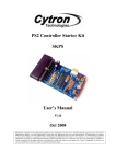
A servo motor is a rotary actuator which produces a rotary motion or torque that
allows for precise control of angular position[1] Basically, servo motor consists of
motor such as dc, ac or brushless dc motor combined with sensor for position feedback.
It is also consist of an output shaft where this shaft can be positioned to specific angular
6
positions by sending the servo a code signal. As long as the coded signal exists on the
input line, the servo will maintain the angular position of the shaft. The angular position
of the shaft will be changes if the code signal is changes. Figure 2.1 will shows the
basic component that have in the servo case.
Drive Gears
Output Spline
Servo Case
Control Circuit
Potentiometer
Motor
Figure 2.1: Servo motor structure
In the servos, even though the motor is very small, it is pretty strong for its size
which it built in control circuitry. The servos are controlled by sending a pulse of
variable width to them. The control wire will used in order to send the pulse. The
parameters for the pulse are minimum pulse, maximum pulse and repetition rate.
Generally, the minimum pulse will be about one millisecond wide while for the
maximum pulse is about two millisecond wide. Repetition rate is the time required from
the servo to change from one position to another. Different servos will have different
constraints on their rotation but all of them will have a neutral position. It means that
the servo will have exactly the same amount of the potential rotation in the clockwise
direction as it does in counter-clockwise direction and the position is always 1.5
milliseconds (ms).
7
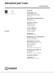
Figure 2.2: Pulse Width Modulation signal
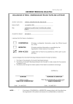
In order to determine the position angle at which the servo will turn is by
determine the duration of pulse that is applied to the control wire. It is called Pulse
Width Modulation (PWM) as shown in Figure 2.2. The servo motor is expects to see a
pulse in every 20ms and the length of the pulse will determine how far the motor turns.
For example, a 1.5 millisecond pulse will make the motor turn to the neutral position
which is 90 degree position. Let say if the pulse is shorter than 1.5millisecond, then the
motor will turn the shaft closer to the 0 degrees. While if the pulse is longer than 1.5
millisecond, then the motor will turn the shaft closer to 180 degrees. This example can
be illustrated in Figure 2.3.
Figure 2.3: Duration of pulse dictates the angle of output shaft
8
In practice, servo motor is extremely useful in robotics world. Servo is widely
used in radio controlled airplanes in order to control the position of surfaces like the
elevators and rudders. Besides that, servo motor is also used in radio controlled cars,
puppets and of course robots.
2.3
Microcontroller
A microcontroller can be defined as a small computer on a single integrated
circuit that contains a processor core, programmable input/output peripherals and
memory. Microcontrollers are often used in a simple control system because of their
many features. Microcontroller must contain at least two primary components which is
random access memory (RAM) and instruction set. RAM is a type of internal logic unit
that will store information temporarily at which it will disappear when the power is turn
off. While instruction set is a list of all commands and their corresponding functions.
Besides that, most microcontrollers also contain read-only memory (ROM),
programmable read-only memory (PROM), or erasable programmable read-only
memory (EPROM). All of these memories are permanent at which they retain what is
programmed into them even during loss of power. They are used to store the firmware
that tells the microcontroller how to operate and also used to store permanent lookup
tables. Moreover, a microcontroller will consist of input/output (I/O) port pins in order
to communicate with other device. The number of I/O pins per controllers varies
greatly, plus each I/O pin can be programmed as an input or output (or even switch
during the running of a program.
9
In addition, most microcontrollers will have circuitry to generate the system
clock. This square wave is the heartbeat of the microcontroller and all operations are
synchronized to it. Obviously, it controls the speed at which the microcontroller
functions. All that needed to complete the clock circuit would be a crystal or RC
component. Therefore we can precisely select the operating speed critical to many
applications.To summarize, a microcontroller contains two or more of the following
elements in order of importance[2].
2.3.1
i.
Instruction set
ii.
RAM
iii.
ROM,PROM or EPROM
iv.
I/O ports
v.
Clock generator
vi.
Reset function
vii.
Watchdog timer
viii.
Serial port
ix.
Interrupts
x.
Timers
xi.
Analog-to-digital converters
xii.
Digital-to-analog converters
Arduino Microcontroller
Arduino can be defined as a tiny computer that can program to process input and
output going to and from the chip[3]. It is an open-source physical computing platform
based on a simple microcontroller board. It is an interactive system that through the use
of hardware and software that can interact with its environment. An Arduino board is
10
made of an 8-bit Atmel AVR microcontroller, 16MHz crystal oscillator and 5-volt
linear regulator, input output pin. Some of them come out with USB connector that
enables it to connect with a computer. Official Arduinos have used the megaAVR series
of chips such as ATmega8, ATmega168, ATmega328, ATmega1280 and ATmega2560.
Arduino can also be connected to the variety of interchangeable add-on modules which
known as shield in order to get extra functionality such as GPS receiver, LCD display
and ethereal connections.
Besides that, an arduino’s microcontroller is also pre-programmed with a boot
loader that simplifies uploading of programs to the on-chip flash memory., compared
with other device that need an external programmer.There are many types of Arduino
board model that have been commercially produced such as Arduino Uno, Mega,
Leonardo, Duemilanove, Mini, and Nano. All these type of Arduino hardware have
different features as shown in Table 2.1
Table 2.1: Arduino board models
Arduino
Processor
Flash EEPROM SRAM Digital With
kB
kB
kB
I/O
Analog
PWM input
pin
Uno
ATmega328P
32
1
2
14
6
6
Mega
ATmega1280
128
4
8
54
14
16
Leonardo
ATmega32u4
32
1
2
14
6
12
Duemilanove
ATmega128
16/32
0.5/1
1/2
14
6
6
16/32
0.5/1
1/2
14
6
8
or
ATmega328P
Nano
ATmega168
or
ATmega328
11
The Arduino IDE (Integrated Development Environment) is used in order to
program the Arduino board. It is a cross-platform application written in Java and is
derived from IDE for the Processing program language and the Wiring project. Its
include codes editor with features such as syntax highlighting, brace matching and
automatic indentation. Besides that, it also capable of compiling and uploading
programs to the board with only a single click. The Arduino IDE comes with a C/C++
library called “Wiring” which make common input/output operation much easier and
Arduino program are written in C/C++language.
2.4
Wireless Communication System
Wireless communication is where information can be transferred between two or
more points that are not connected by an electrical conductor or wires[4]. Basically,
wireless would be referring to a dual purpose transmitter and receiver device. It is also
refer to any type of operation that is implemented without using of wires such as
wireless remote control. The distances that could be involved maybe short or very long.
Wireless communication can be via radio frequency, microwave communication,
Bluetooth communication and etc.
2.4.1
BluBee
BlueBee (Figure 2.4) is Bluetooth wireless modules that have been developed by
a company called Cytron Technologies. This module provides users a wirelessly remote
12
control on their microcontroller circuit through serial port communication services. It is
suitable for any type of microcontroller system that has 3.3V power output. BlueBee
consist of two mode of operation which is AT mode and Transmit mode. The AT mode
is used to set the control parameters and send control order. The baud rate for this mode
is 38400bps only. While Transmit mode is used to transfer or receive signal or data to
other Bluetooth devices.
Figure 2.4: BlueBee module
The BlueBee module is comes with an on-board antenna which provides a better
signal quality. It is act like a transparent serial port that will work with variety of
Bluetooth adapter. BlueBee is a slave module which means communication among two
Bluebee is not possible[5]. BlueBee module is consisting of 20 pins but only 9 pin is
available. Table 2.2 shows the functional pin and their description. Besides that, Table
2.3 will show the absolute maximum rating of Bluebee module parameters.
13
Table2.2: BlueBee pin function
Pin
Name
Description
1
3V3
3.3V (+) supply for BlueBee module
2
TXD
UART Data output
3
RXD
UART Data input
5
RESET
6
P9
Connection indicator, High = Connected, Low = No connection
8
P8
LED, Mode indicator, connected the BlueBee status LED
10
GND
Ground port
12
CTS
UART clear to send, active low
16
RTS
UART request to send, active low
Reset for BlueBee module
Table 2.3: BlueBee absolute maximum rating
Symbol
Parameter
Min
Max
Unit
3.0
3.6
V
3.3
Operating voltage
RX
Receiver pin of BlueBee module
0
3.3
V
TX
Transmit pin of BlueBee module
0
3.3
V
Reset
Reset pin of BlueBee module
0
3.3
V
GND
Ground
0
0
V
14
2.5
Researches on Spherical Mobile Robot Worldwide
The term spherical robot is used to describe two very different types of robots.
Firstly, spherical robot is a robot arm that forms a spherical coordinate system with two
rotary joints and one prismatic joint. The term spherical robot is also used to describe
mobile “ball-like” robots that move along the ground by rolling about their outer
spherical shell. This second definition is the focus of this project.
Spherical mobile robots have been described by only a few authors and also
being made commercialized by some companies. There is several type of constructing
method which used a variety of different principle of locomotion. These principles of
locomotion can be categorized into four which are:
Hamster Ball
Pendulum Driven
Multiple-Mass-Shifting
Deformable Body
2.5.1
Hamster Ball
The sphere style of a hamster ball is where one with an inside driving unit (IDU)
which transfer directly to the inside surface of a hollow spherical shell. This type of
principle can be constructing using two methods which are sprung central member and
internal car resting on the bottom as shown in Figure 2.5.
15
a) Sprung Central Member
b) Internal Car
Figure 2.5: Hamster Ball Concept
The sprung central member design consists of three main elements which is a
single driven wheel at the bottom, a spring element, and fixed wheel at the top. The
spring will maintains contact between the driving wheel and the inside surface of the
sphere. The driven wheel is rotated about its contact point with the sphere in order to
steer by applying a torque between the wheel and the inertia of the rest of the assembly.
While for the internal car design is mostly closely resemble a hamster inside the
hamster ball. The sphere will start to roll forward when the car begin to drive up the
inside surface of sphere. The car can have variety of well-known steering mechanism
such as 4-wheel, 3-wheel or front-wheel steering as well. This is because directional
control of the sphere is maintained by driving internal car in the desired direction.
The Rollo robot is one of the spherical mobile robots that have used this kind of
principle. It was develop by a team from Helsinki University of Technology,
Finland[6]. They have made two prototypes where first prototype used the sprung
central member method design while the second prototype of Rollo robot used a unique
design that was a combination of sprung central member and the internal car
mechanisms as shown in Figure 2.6. Besides that, this method also has been developed
16
by Bicchi. He has introduces a spherical vehicle consisting of a hollow sphere with a
small car resting on the bottom[7].
Figure 2.6: Rollo Prototype (a) 2nd Prototype (b) 1st Prototype
The hamster ball concept has several advantages and disadvantages. The
advantages of this concept design for both sprung central member and internal car
driven is they locate the majority of their mass close to the surface of the spherical shell
which maximize the motion of rolling performance. The design of the spherical robot is
much simple and their drive mechanisms are straightforward to handle. Besides that,
this method is possible to build a fully omnidirectional hamster ball design by using an
internal car with omnidirectional wheels.
The disadvantages of this hamster ball concept are that the internal surface of
the spherical shell needs to be uniform and smooth in order for the drive wheels to
function well. In addition, the wheels must maintain constant with the surface shell at
all times because there is a friction between its wheels and the sphere. Moreover, the
internal car may lose contact or even flip over if there is collision or impact with
obstacles.
17
2.5.2 Pendulum Driven
Simple spherical mobile robot can be developed using a pendulum based design.
This type of method of construction is typically has a main drive shaft fixed to the
spherical case and an offset mass hanging from the drive shaft. The spherical mobile
robot will move forward when a torque is applied between pendulum and the drive
shaft. The spherical mobile robot also can steer if the pendulum is tilted to the side
which causing the main drive shaft to form an angle with the ground. Figure 2.7 shows
the concept method of pendulum drive.
a) Side view with
pendulum rotate up for
driving forward
b) Side view with pendulum
tilted to the side for
steering movement
Figure 2.7: Pendulum Driven Concept
Groundbot robot is one of the spherical mobile robot that have been used this
type of constructing method. It was developed by a Swedish company, Rotundus[8].
The application of this robot is for patrolling and monitoring industrial locations. It is
equipped with cameras mounted in transparent domes on the sides of the robot. Figure
2.8 shows the picture of the robot.
18
Figure 2.8: Groundbot, Rotundus
The design of this robot consists of a motor attached to the horizontal axis of the
sphere. Then, the pendulum is located at the center which is drops down. The sphere
will roll as long as the weight of the pendulum has enough inertia when the motor is
activated.The advantages of pendulum driven principle are the mechanism of the robot
is relatively straightforward. The shell of the spherical robot is dimensionally noncritical due to the internal drive mechanism which is only interface with the spherical
shell at two fixed points. Besides that, this robot can have accurate and precise
measurement of the spherical shell and the pendulum compared to hamster ball design
concept.
On the other hand, the disadvantage of this concept design is that the mechanical
design would be more challenging compared to other concepts. Besides that, the torque
required at the main drive shaft is much higher that the torque required in the hamster
ball design. Moreover, the pendulum drive mechanism is not an omnidirectional
movement. Once it is stopped, a sphere with a pendulum drive must begin travelling in
the same instantaneous trajectory before travelling in an arc to change direction.
19
2.5.3 Multiple-Mass Shifting
The multiple-mass shifting concept design incorporates three or four masses that
can be move independently along linear guides inside the sphere. The location of the
center of mass of the spherical mobile robot can be controlled by coordinating the
motion of the masses thereby enabling the robot to move in desired location. Spherobot
is one of the robots that have used this concept design which have been proposed by R.
Mukherjee. In his design, it consists of a central body with weights distributed radially
along spokes fixed inside surface of the sphere[9]. The weights can be the motors which
move along the axes to change the center of mass.
Figure 2.9(a) shows the design of the Spherobot. Besides that, A. Javadi and P.
Mojabi also have used similar design in order to construct a spherical mobile robot
called August [10]. They had implemented their robot with a stepper motors located at
center of the robot and four axes are mounted in tetrahedral pattern as shown in Figure
2.9(b).
(a)
Figure 2.9: Spherobot Design (a) and August (b)
(b)
20
The advantage of the multiple-mass shifting concept is that it is fully
omnidirectional. It can instantaneously begin moving in any direction from a standstill
with this propulsion mechanism. Besides that, it can offer very precise control of the
center of mass of the sphere. However, there are some drawbacks to the design. The
mechanical design of this robot will be very complex and the controls to coordinate the
masses are complicated as well. High power of actuators is needed for the masses
rapidly reciprocate along their axes in order to roll quickly in a straight line. Thus this
makes it very inefficient.
2.5.4 Deformable Body
Spherical mobile robot with this concept design will deforms its normally
spherical shape in order to propel itself. A deformable sphere can control the position of
its center of mass relative to where the sphere contacts the ground by continuously
altering its shape.
Koharo robot is one of the robots that used this type of concept design. This
robot was developed from Ritsumeikan University in Japan. This robot is consisting of
a wheel and a sphere with flexible outer structures and shape memory alloy (SMA)
actuators[11]. The outer structure of the wheel or sphere can be deformed to cause it to
roll by contracting and expanding the SMA wires in coordination. The wheel is a
flexible ring with radial, SMA spokes as shown in Figure 2.10.
21
Figure 2.10: Deformable wheel rolling. Video snapshots of the wheel rolling over a
period of 6 second
The disadvantage of this concept design is that the motion of the wheel and
sphere is very slow since the cycle rate of the SMA actuators is also very slow. Besides
that the power source is external and the prototype has to be tethered during operation.
2.5.6
Commercialized Spherical Mobile Robot
Some authors have been described spherical mobile robot was very useful for
some application if it equipped with environmental sensor such as a vision infrared
camera, loudspeaker, microphone, sensor for radioactivity, heat, and smoke detection.
These spherical mobile robots also have been commercialized by some company. In
2002, the SONY Corporation has developed a spherical mobile robot as a tool for
entertainment purpose called Q.taro[12]. This robot consists of 36 sensors which it
switches on and off by sensing human hand and avoid obstacle automatically. It is
22
developed to foster emotional connection between human and robot technology and
also can be used as playing toy for children. Besides that, Japan also produces TamaRobo ball robot as entertainment as well. This robot comes with a small round cup that
consists of four light sensors. This robot will roll and changing their direction when
there is a light source. Q-taro and Tama-Robo robot is shown in Figure 2.11 below.
Figure 2.11: Q-taro and Tama-Robo
Another application of spherical mobile robot is space exploration. It is one of
the attractive application areas of spherical robot[13]. This is because this robot
provides protection from radiation for inner structure that consists of electronic circuit
and necessary hardware. The Massachusetts Institute Technology (MIT) in the US is
developing spherical robot that can move by bouncing and rolling[14]. These robots can
be sent to other planets arranged altogether in an egg-carton-like container.
23
2.6
Summary
As a summary, this chapter have discussed about servo motor and
microcontroller which is very important components in developing the controlled
system in robotics world. This chapter also has discussed about Arduino microcontroller
at which this microcontroller is very user friendly and easily to use and program.
Besides that this chapter had talked about BlueBee which is Bluetooth device that can
use for wireless communication system to communicate either between computer and
microcontroller or among the computer only. Moreover, this chapter has explained
some of related work that has developed by previous researches on method of
development of Spherical Mobile Robot. In addition, there is some commercialized
spherical robot and its application that has described in this chapter
CHAPTER 3
SYSTEM DESIGN
3.1
Introduction
This chapter will discuss about the method and system design that will be used
in order to build the spherical mobile robot with omnidirectional movement. Firstly, it
will give an overview about the hardware design. It will consist of mechanical and
electronic design. Besides that, this chapter also will explain about the software design.
It will consist of spherical mobile robot programming and development of graphical
user interface (GUI) using Microsoft Visual Basic.
3.2
Hardware Design
Driving mechanism is very important and need to be considerate in order to
make the spherical mobile robot moved Omni directionally and perform the task
properly and reliable. Before designing the robot structure, it is very important to
25
choose the suitable concept of locomotion principle. After studied the related
references, the best way to make the spherical mobile robot roll in its outer shell is by a
mechanism that will change the center of gravity or generating a force to the robot. This
can be illustrate in Figure 3.1
Figure 3.1: Principle of Locomotion
Based on this principle, spherical mobile robot will generate motion by using a
center of mass displacement. When the center of mass is displaced a horizontal distance
from the center of the sphere, the force due to gravity will creates a moment on the
sphere, causing it to roll. In this project, the input torque of the servo motor will
transferred to the center of shaft which is connected to the mass and this moves the
center of gravity.
26
3.2.1
Mechanical Design
The Spherical Mobile Robot was built based on several mechanical components.
There is outer spherical shell, body, roll castor, servomotor, U-joint connector and
rotary connector. For the body, it is built from acrylic sheet and aluminum rods.
Before the actual robot is built, the internal structure of the Spherical Mobile Robot was
designed as shown in Figure 3.2. From the design, the size of the internal structure of
the robot needs to be considered so that it can suit with the outer spherical shell.
1
3
4
2
6
5
Figure 3.2: Spherical Mobile Robot design
27
1. Electronic platform part which consist of Arduino Uno, cube servo motor driver
and Bluetooth module
2. G15 cube servo
3. Main body of internal structure
4. Roller castor
5. U-joint connector
6. Weight/ Load
After the internal structure is completely designed, the real Spherical Mobile
Robot was constructed. The outer shell of the spherical robot is made by two clear
plastic lamp’s globe as shown in Figure 3.3 at which these two globes is cut into
hemisphere shape and combined it to form a spherical shape. The size of this spherical
globe is 12 inches of diameter.
Figure 3.3: Outer spherical shell
The body of the internal structure of the Spherical Mobile Robot is constructed
in a triangular shape and roller castor is placed at every edge of the shape so that it will
give less friction between the internal structure and the outer spherical shell. These
28
castors need to really fix with outer case and smooth enough so that this will maintain
the internal structure thus make the outer shell to roll in desired location. The structure
of the body is shown in Figure 3.4.
Figure 3.4: Body of internal structure
Two cube servos is placed at the bottom of the internal structure’s body at which
the cube servos will attach together to form a driving mechanism. The first servo is
attached with the body of internal structure while the other one will attach with U-joint
connector which stick with battery holder that act as a load The structure can be shown
in Figure 3.5.
29
Figure 3.5: Driving mechanism construction
Electronics part is placed at the top of the body of the internal structure. It is
consist of Arduino Uno board, cube servo motor driver, Bluetooth module and power
supply holder. It can be shown in Figure 3.6.
Figure 3.6: Electrical part construction
30
The overall outlook of the final version of the Spherical Mobile Robot is shown in
Figure 3.7. The final structure is constructed based on the continuous modification and
improvement.
a) Complete internal structure
b) Overall outlook
Figure 3.7: Final structure of Spherical Mobile Robot
31
3.2.2
Electronic Design
In electronic part design, the circuit can be divided into three parts which are the
main board, driver circuit to control the servo motor and communication circuit board
which consist of SKXbee board and Bluetooth module. All these circuit board will be
connected together. Figure 3.8 shows the block diagram for summarizes the connection
between the electronic components of the Spherical Mobile Robot.
SKXbee Board +
Bluebee
Power Supply
9V
Arduino Uno
Microcontroller
Cube Servo
Motor Driver
G15 Cube
Servo
Power Supply
12V
Figure 3.8: Block diagram of circuit connection
3.2.2.1 Main Board Circuit
Arduino Uno microcontroller board as shown in Figure 3.9 is used as the main
board which acts as a brain of the Spherical Mobile Robot. This microcontroller board
is based on the ATmega328 as the main controller to control the hardware performance.
32
This microcontroller board can simply connect to a computer with USB cable in order
to program the robot. It also consist of power jack which is use to connect with a power
supply with AC-to-DC adapter or battery.
14 Input/output pin
USB connection
ATmega328
microcontroller
Power jack
6 Analog inputs
Figure 3.9: Arduino Uno board
3.2.2.2 Cube Servo Motor Driver
G15 Shield is used as cube servo motor driver in order to control the G15 cube
servo. Figure 3.10 shows the hardware connection between Arduino Uno and G15
Shield. It is simply stacking up the shield onto the main board. The EXT_MPWR
connector is used to connect with power supply for servo motor to operate. It is required
to solder EXT pad and MPWR pad together on MPWR_SEL for external motor power.
Only one of the G15 cube servo ports is used to connect with the servo motor.
33
Connect 12V
power for servo
motor
Select EXT for
external motor
power
G15 Cube Servo
ports
Figure 3.10: G15 Shield setup
3.2.2.3 G15 Cube Servo
G15 Cube servo motor as shown in Figure 3.11 was used as driving mechanism
to move the spherical mobile robot in any direction. Two servo motor is needed to make
a movement at which both of them is attached together. One of the servos is used to
change the direction of movement while the other one is used to change the center of
mass of the Spherical Mobile Robot that makes it roll in its outer shell.
34
Figure 3.11: G15 Cube Servo
G15 Cube Servo is a modular smart serial servo which incorporates gear
reducer, precision high torque DC motor and control circuitry with networking
functionality. It is made with high quality engineering plastic to provide high necessary
strength and can sustain high external force. G15 provides 360 degree endless turn
control with resolution up to 0.33o. G15 Cube servo has an output connect (output shaft)
on one surface and specially designed slide-fit latch on 5 other surfaces. The operating
voltage of this cube servo and its current is 6.5-12V and 1.5A (max at 12V)
respectively. While it speed is 60RPM (no load at 12V). Two G15 cube servo is
connected in daisy chain connection to create a servo on a single line at which these
servos then connected with G15 shield. It can be shown in Figure 3.12. G15 cube servo
is consisting of three terminals which are GND, V+ and DATA.
35
Figure 3.12: Daisy chain connection
3.2.2.4 SKXbee Board and Blubee
SKXbee board is a starter kit for wireless communication module. It is used with
Bluebee in order to communicate wirelessly from a computer to microcontroller. Blubee
is plugged into the socket provided in the SKXbee board. Then it is interfaced with the
main board which is Arduino Uno microcontroller board. This connection can be shown
in Figure 3.13. In this connection, receiver (RX) and transmitter (TX) pin of Arduino
Uno microcontroller and SKXbee was cross connected. It means TX pin of
microcontroller is connected to RX pin of SKXbee while RX pin of microcontroller is
connected to TX pin of SKXbee. The transmitter and receiver status LED of SKXbee
board is blinked if BlueBee transmitter pin and receiver pin transmit or receives data
from the microcontroller.
36
Receiver status
LED
Transmitter
status LED
Figure 3.13: Connection for Communication system
3.2.2.5 Power Supply
The power supply is the most critical unit in an electronic project. One Lithium
Polymer (LiPo) rechargeable, 11.1V, 2200mAh battery and one standard 9V battery is
used to supply power to the Spherical Mobile Robot is quite small, light and has longer
life. This battery was connected to the cube servo motor driver to support the servos. It
also used as a load for the robot. While, for 9V battery was connected to the Arduino
Uno microcontroller board. It is very important to used different battery for main board
and motor driver because the motor required a lot of current in order to move.
37
3.3
Software Design
Basic process of writing software for the Spherical Mobile Robot is showed in
Figure 3.14.
Start
Desire robot movement
Writing Program
NO
Compile the program
YES
NO
Download to the
microcontroller
Test the robot
movement
YES
Finish
Figure 3.14 Process flow of writing software
38
3.3.1
Program Download
Arduino IDE (Integrated Development Environment) software as shown in
Figure 3.15 is used to program the Spherical Mobile Robot. This software will used C
language to write a program. Before the program is uploaded into the microcontroller
using USB cable, first thing need to be done is selecting the Arduino board and the
selected USB port. This can be illustrated in Figure 3.16. After that, the program that
have been wrote can be compile to check whether the code is correct or not before it is
uploaded to Arduino microcontroller board. Once the data has been uploaded to the
board successfully it will get Done Uploading message in the IDE and the RX/TX
LED’s on the Arduino Uno board will stop flashing.
Figure 3.15: Writing program by Arduino IDE software
39
Figure 3.16: Selecting Arduino board and USB port
3.4
Graphical User Interface Development
Graphical user interface (GUI) is a method to interface between computer and
external device which can manipulate by a mouse or a keyboard. So that user can easily
use a GUI to control operation of hardware and producing a data. There are many
programming tools that can be used to design a GUI platform such as Microsoft Visual
C++, Labview, Matlab, Microsoft Visual Basic and Java programming language. In this
project, Microsoft Visual Basic 2010 is used to develop a simple GUI platform.
40
3.4.1
GUI Design
First step in order to design a GUI with Microsoft Visual Basic is creating a new
project by selecting Window Forms Application as shown in Figure 3.17. After that,
designing the platform of the GUI can be started by using Toolbar which is provided.
This Toolbar consist of various GUI components such as Labels, Buttons, Text,
GroupBox and Menus that will represent a screen element which used to display
information and interact with the program. It can simply drag the GUI components to a
window surface or layout during the process of creating GUI platform as shown in
Figure 3.18. Besides that, it can be easily changed the specific size, name, background
color, design name and other properties due to own creativity and idea in Editing
Properties. Figure 3.19 shows the detail of the final GUI layout of this project.
Figure 3.17: Creating project using Visual Basic
41
Toolbox
GUI Platform
Editing Properties
Figure 3.18: GUI components
ComboBox
GroupBox
Button
Label
Text
ImageBox
Figure 3.19: GUI layout design
42
Based on Figure 3.19, GUI layout design is consist of six different GUI
components which are GroupBox, Label, Text, ComboBox, ImageBox and Button. In
this layout, it is divided into two GroupBox which is for control panel and COM port
selection. In control panel box, it has eight buttons that representing eight different
directions for the Spherical Mobile Robot movement. While in COM port selection box
consist of three buttons, one ComboBox and a TextBox. COM port form is needed to
detect serial communication channel and connect that serial communication channel for
communicate between a computer and the spherical mobile robot.
3.4.2
Writing Program
Microsoft Visual Basic 2010 is an object oriented and event driver
programming language even all windows also are event driven. It means that the user
can decide their program flow by simply ‘double click’ the component on the GUI
platform. When one of the components is click, code of the window will appear as
shown in Figure 3.20. Then, writing a program can be done under the Private Sub (start)
and End Sub (end).
Add Statement here
Figure 3.20: Program writing in Visual Basic
43
3.8
Summary
As a summary of this chapter, hardware design, software design and GUI
development have been discussed in detail. In hardware design, mechanical and
electrical design that is used in construction the Spherical Mobile Robot has explained.
While process of writing and download program of microcontroller board had been
discuss under software design. Lastly, for GUI development, it is all about the designing
of the control system of the Spherical Mobile Robot.
CHAPTER 4
RESULT AND DISCUSSION
4.1
Introduction
This chapter will discuss about the experimental result and analysis that have
been carried out which is about the movement of the Spherical Mobile Robot. It is
consisting of the functionality of the Spherical Mobile Robot at which three tests has
been conduct; efficiency test of communication system, efficiency test on the GUI and
overall movement test of Spherical Mobile Robot.
4.2
Efficiency Test on Wireless Communication System
HyperTerminal software is used in order to test the functionality of
communication system at which Bluebee is used to communicate between Spherical
Mobile Robot and computer. Firstly, AT mode of Bluebee module is used to test
whether this Bluetooth module able to communicate or not. The 38400bps baudrate will
45
be setup in the HyperTerminal and the Bluebee is connected to a computer. The
Bluebee is working when send ‘AT’ to Bluebee, the HyperTerminal will response OK.
The result can be shown in Figure 4.1.
Figure 4.1: BlueBee test using HyperTerminal
After checking the functionality of the BlueBee, the movement of two cube
servo is tested by using HyperTerminal. This test is done to ensure that the servos can
move even it is not connect directly with a computer. In other words it can move
wirelessly. The result of this test is shown in Figure 4.2
46
a) HyperTerminal Display
b) 90 degree movement
c) 0 degree movement
Figure 4.2 Servo Movement Test using HyperTerminal
Initially the Arduino Uno microcontroller is programmed to move the second
servo that is attach with the U-joint connector. Based on the result, the second servo is
moved to 90 degree position when button number 1 on the keyboard is pressed while
the command was displayed in the HyperTerminal. Then, the servo is moved to 0
degree position as button number 2 is pressed and the command was displayed as well.
The servo will not move if other button is pressed. Based on these two tests, it can be
summarize that BlueBee module is efficient as wireless communication module and the
system is working properly as required.
47
4.3
Efficiency Test on GUI
The functionality and the capability of the Graphical User Interface (GUI) as the
control system of Spherical Mobile Robot is Tested. Firstly, the connection between the
computer and the robot need to be tested. The COM port selection box in GUI will
search the available COM port channel and then the text box in the GUI layout will
show whether COM port channel is connected or not. The result of this test is shown in
Figure 4.3.
Figure 4.3: Connectivity Test using GUI
Based on the result, the available COM port for the wireless communication
device, BlueBee is COM 11. The result shows that this com port is connected with the
computer which interfaces with GUI. Besides that, status LED on BlueBee was blinked
2 times in 1 second means that the Bluetooth Wireless link is successfully created.
Therefore, GUI can be used to control the Spherical Mobile Robot wirelessly.
48
After that the functionality of the control panel button is tested. The control
panel box in GUI platform is consist of eight button which represent the direction that
Spherical Mobile Robot can move to desired location. So the test has been conducted as
shown in Figure 4.4.
(a)
(c)
(b)
(d)
Figure 4.4: Control position of GUI test
49
The result shows four basic movement of the Spherical Mobile Robot that has
been controlled by a computer which interfaces with GUI. When button 1 in the control
panel box is clicked, the servo is moved in forward direction as shown in Figure 4.4 (a).
Then, the servo is moved in backward direction (Figure 4.4b) when button 2 is clicked.
The Spherical Mobile Robot will moved to the left (Figure 4.4c) and to the right
direction (Figure 4.4d) when button 3 and 4 is clicked respectively. Besides, this four
buttons, another four buttons also have been tested and as results the robot is able to
communicate and react to move in the correct direction as programmed.
As summarize the GUI development is successfully worked as expected. This
GUI is able to communicate and easily controlled the movement of Spherical Mobile
Robot. It is quite efficient because it is able to communicate wirelessly via Bluetooth
device.
4.4
Overall Movement Test of Spherical Mobile Robot
Overall movement test of Spherical Mobile Robot need to be conducted based
on the main objectives of the project which is to build a Spherical Mobile Robot with
omnidirectional movement. In this test, the movement of the robot will be observed and
analyzed so that it would be able to identify the strength and weaknesses of the robot.
Firstly, the test was conducted to analyze the ability of the robot to move forward and
backward direction. Figure 4.5 shows the result of the movement.
50
2
1
3
4
a) Forward Movement
4
3
2
1
b) Backward Movement
Figure 4.5: Robot move forward and backward direction
Based on the results, it shows that the Spherical Mobile Robot is able to move in
forward and backward direction. Based on the observation and analysis of the test, the
robot needs bigger momentum at the beginning which is required more speed of the
servo’s rotation. With this momentum the internal structure of the robot is able to
change their center of mass thus causing the robot to roll in its outer shell. At a certain
time, the internal structure of the robot has difficulty to sustain its posture because the
roller castor is stuck at the joining part of the outer spherical shell.
51
Secondly, experiment was conducted to identify the ability of the Spherical
Mobile Robot to move left and right direction. The results obtained are shown in Figure
4.6.
4
3
2
1
a) Left Movement
1
2
3
b) Right Movement
Figure 4.6: Robot move left and right direction
4
52
Results in Figure 4.6 shows that the Spherical Mobile Robot is able to move left
and right direction. From the observation, it showed that the time taken for the robot to
start moving is much longer than the first experiment which is moving forward and
backward. This is because the robot need to change the position angle of the two servos
compared to first test which is required only one servo. The same problem also occurred
at which the internal structure of the robot is stuck at the joining part of spherical shape.
This is because the joining part is not fixed really tight and material of the spherical
shell is not solid enough, thus causing it to deform its shape due to the weight of the
internal structure. Therefore the robot has some difficulty to move smoothly to the
desired location. Besides that, Spherical Mobile Robot also has been tested for other
four type of movement as illustrate in Figure 4.7
Figure 4.7: Four different movement
Based on experiment that has been conducted for this type of movements, it can
be observed that the robot is able to move in such way. This is because of the robot
structure which is spherical in shaped. There is some problem while the robot is
53
moving. The robot cannot be able to maintain their direction of movement due to
instability of the internal structure. As summarize, Spherical Mobile Robot is able to
move in any direction (omnidirectional) but its need some modification so that this
robot became more stable, rigid and smooth.
4.5
Summary
This chapter has discussed about the testing and experiment analysis being done
on the Spherical Mobile Robot. Firstly is about the functionality and efficiency of the
communication system. It shows that the robot able to communicate wirelessly with a
computer. Secondly is about the functionality of the GUI development. GUI is an
attractive control system and easy to use. All the button function in the GUI design is
working properly as expected. Lastly is about overall testing of the Spherical Mobile
Robot movement. The robot is able to move omnidirectional where it can move in any
direction.
CHAPTER 5
CONCLUSION
5.1
Conclusion
Generally, this project has achieved the basic objective and scope as discussed
in chapter one. This spherical Mobile Robot can be move omnidirectional where it can
move in any direction to the target positions. Besides that this robot can be controlled
wirelessly from a computer through Bluetooth device. Moreover, Graphical User
Interface has been successfully developed as a controller system for the robot.
As a conclusion, this project is successfully designed, implemented and tested.
This undergraduate project have given the author opportunity to acquire the knowledge
and experience in designing a mobile robot, this also enhances my understanding
towards hardware and software interfacing for a mechatronic system. For the next robot
development, it is hoped that this Spherical Mobile Robot can be reconstructed with
some modification to improve the abilities and to provide benefits in the feature also be
able to be marketed and commercialized.
55
5.2
Project Limitations
One of the limitations of this Spherical Mobile Robot is that it would not be able
to roll on slopes. This is due to its spherical structure. It will roll down to the lowest
level automatically without giving any command to it to move in such way when this
robot is being place on slopes. Besides that, this Spherical Mobile Robot would not be
able to climb up a very steep slope. This is because the input torque of the servo motor
not has enough strength to drive the robot and carried the weight.
5.3
Suggestion and Future Development
The spherical outer shell for this mobile robot is made of clear plastic globe
lamp which has been modified. This type of shell is not quite strong to hold the internal
structure of the robot. Thus this has caused the shape of the spherical shell to deform.
For future development, solid full sphere that made of good material can be used.
Besides that gyroscope accelerometer also can be used for the stability of the robot For
further enhancement, this Spherical Mobile Robot can be integrated with intelligence by
adding some useful equipment. For example, the spherical mobile robot can be used to
carry out tasks such as surveillance, piloting, sensing and carried out hostile
environment if the robot is mounted with a camera and some sensors.
56
REFERENCES
1. Robotzone. (2012). How do servos motor work. Servocity.com.
URL: http:// www.servocity.com/html/how_do_servos_work_html
2. Laurence A. Duarte. The Microcontroller Beginner’s Handbook. 2
nd
Edition.
United States of America: Prompt Publication 3-5; 1998
3. Arduino. (2012). Introduction of Arduino. Arduino.cc.
URL: http://arduino.cc/en/Guide/Introduction
4. Wikipedia. (2013). Wireless
URL: http// en.wikipedia.org/wiki/Wireless
5. Cytron Technology [2012]. User Manual Cytron Bluetooth module BlueBee
[Brochure]. Cytron Technologies Sdn. Bhd
6. A. Halme, J. Suomela, T. Schonberg, and Y. Wang (1996), “A spherical mobile
micro-robot for scientific applications,” Design of Spherical Rolling Robot,
Carnegie Mellon University, Pittsburgh: Research Paper.
7. Bicchi. A. (1997) “Introducing the Spherical: An Experimental Testbed for
Research and Teaching in Nonholonomy.” University of Pisa: Research report.
8. Knight.W.
(2005),
Spherical
NewScientist.com news service.
robot
provides
rolling
security
cover.
57
URL: http:// www.newscientist.com/article.ns?id=dn6932
9. Mukherjee, R “Design Challenges in the Development of Spherical Mobile
Robot.” Robotic Ball Technology Study for Planetary Surface Mission. NASA
JSC/EV George Studor. May 11, 2010
10. Javadi.A.H. “Introducing Spherical Robot: A Nonholonomic Omni- directional
Rolling Robot,” Azad University of Qazvin, Iran: Research report.
11. Sugiyama, Y. & Hirai, S.”Crawling and Jumping by a Deformable Robot”,
International Journal of Robotics Research, Vol. 25, No 5-6, pp. 603-620, 2006
12. Nakamura, T. (2002). Hikaru HALO, SONY ga kyungata no robotto QTARO wo
kaihatu. IT media news (Japanese).
URL:http://www.itmedia.co.jp/news/0203/27/qtaro.html
13. F. Michaud, J. Lafontaine, and Serge Caron. (2001) “A spherical robot for
planetary surface exploration,” in Proc. 6th International Symposium on
Artificial Intelligence, Robotics and Automation in Space, 2001
14. Young,
K.
(2006).
Spherical
micro-robots
could
explore
Mars.
NewScientist.com news service.
URL:
http://
space.newscientist.com/article/dn9610-spherical-microrobots-
could-explore-mars.html
APPENDIX A
Source Code of Visual Basic
'created by Muhamad Zamir Bin Abu Kassim,
'Control Spherical Mobile Robot with Visual Basic
'2013
Imports System.IO
Imports System.IO.Ports
Imports System.Threading
Public Class Form1
Dim COMport As New SerialPort
Dim transmitt As Integer
Private Sub Form1_Load(ByVal sender As System.Object, ByVal e As System.EventArgs)
Handles MyBase.Load
For i As Integer = 0 To My.Computer.Ports.SerialPortNames.Count - 1
cbcom.Items.Add(My.Computer.Ports.SerialPortNames(i))
Next
cbcom.Text = cbcom.Items.Item(0)
btndisconnect.Enabled = False
FowardMov.Enabled = False
BackwardMov.Enabled = False
LeftMov.Enabled = False
RightMov.Enabled = False
End Sub
Private Sub btn90L_Click_1(ByVal sender As System.Object, ByVal e As
System.EventArgs) Handles FowardMov.Click //command for forward direction
If transmitt = 1 Then
COMport.Write("0")
End If
End Sub
Private Sub btn90R_Click(ByVal sender As System.Object, ByVal e As System.EventArgs)
Handles BackwardMov.Click
// command for backward direction
If transmitt = 1 Then
COMport.Write("1")
End If
End Sub
Private Sub btn180L_Click(ByVal sender As System.Object, ByVal e As System.EventArgs)
Handles LeftMov.Click
//command for left direction
If transmitt = 1 Then
COMport.Write("3")
End If
End Sub
Private Sub btn180R_Click(ByVal sender As System.Object, ByVal e As System.EventArgs)
Handles RightMov.Click
//command for right direction
If transmitt = 1 Then
COMport.Write("2")
End If
End Sub
Private Sub Label1_Click(sender As System.Object, e As System.EventArgs) Handles
Label1.Click
End Sub
Private Sub btnsearch_Click(ByVal sender As System.Object, ByVal e As
System.EventArgs) Handles btnsearch.Click //searching for available comport
cbcom.Items.Clear()
For i As Integer = 0 To My.Computer.Ports.SerialPortNames.Count - 1
cbcom.Items.Add(My.Computer.Ports.SerialPortNames(i))
Next
End Sub
Private Sub btnconnect_Click(ByVal sender As System.Object, ByVal e As
System.EventArgs) Handles btnconnect.Click
btnconnect.Enabled = False
btnsearch.Enabled = False
COMport.PortName = cbcom.Text
COMport.BaudRate = 19200
COMport.DataBits = 8
COMport.Parity = Parity.None
COMport.StopBits = StopBits.One
COMport.WriteTimeout = 1000
COMport.ReadTimeout = 1000
Try
COMport.Open()
FowardMov.Enabled = True
BackwardMov.Enabled = True
LeftMov.Enabled = True
RightMov.Enabled = True
btnconnect.Enabled = False
btndisconnect.Enabled = True
transmitt = 1
txtcom.Text = COMport.PortName & " is connected"
Catch ex As Exception
COMport.Close()
MsgBox("The choosen COM port is not available")
txtcom.Text = "Please choose other COM ports"
btnsearch.Enabled = True
btnconnect.Enabled = True
btndisconnect.Enabled = False
FowardMov.Enabled = False
BackwardMov.Enabled = False
LeftMov.Enabled = False
RightMov.Enabled = False
End Try
End Sub
Private Sub btndisconnect_Click(ByVal sender As System.Object, ByVal e As
System.EventArgs) Handles btndisconnect.Click
COMport.Close()
btnsearch.Enabled = True
btndisconnect.Enabled = False
btnconnect.Enabled = True
FowardMov.Enabled = False
BackwardMov.Enabled = False
LeftMov.Enabled = False
RightMov.Enabled = False
transmitt = 0
txtcom.Text = COMport.PortName & " is disconnected"
End Sub
Private Sub cbcom_SelectedValueChanged(ByVal sender As System.Object, ByVal e As
System.EventArgs) Handles cbcom.SelectedValueChanged
If COMport.IsOpen = True Then
If String.Compare(cbcom.Text, COMport.PortName) Then
MsgBox("Change COM while connected is not allowed")
cbcom.Text = COMport.PortName
End If
End If
End Sub
Private Sub PictureBox1_Click(ByVal sender As System.Object, ByVal e As
System.EventArgs) Handles PictureBox1.Click
End Sub
Private Sub Button2_Click(ByVal sender As System.Object, ByVal e As System.EventArgs)
Handles Button2.Click
//command for lower right direction
If transmitt = 1 Then
COMport.Write("7")
End If
End Sub
Private Sub Button3_Click(ByVal sender As System.Object, ByVal e As System.EventArgs)
Handles Button3.Click
//command for upper left direction
If transmitt = 1 Then
COMport.Write("4")
End If
End Sub
Private Sub Button4_Click(ByVal sender As System.Object, ByVal e As System.EventArgs)
Handles Button4.Click
//command for lower left direction
If transmitt = 1 Then
COMport.Write("6")
End If
End Sub
Private Sub Button5_Click(ByVal sender As System.Object, ByVal e As System.EventArgs)
Handles Button5.Click
//command for upper right direction
If transmitt = 1 Then
COMport.Write("5")
End If
End Sub
End Clas
Source Code of Spherical Mobile Robot
#include <G15.h> // include the library
#define LED_BOARD 13
G15 servo1(1),G15 servo2(2); //declare G15 Class Object: servo1:ID and servo2=ID2
void setup()
//initialize the arduino main board’s serial/UART and control pins
{
G15ShieldInit(19200,3,8);
servo1.init(), servo2.init();
// call the init function to init servo obj.
pinMode(LED_BOARD,OUTPUT);
// init LED indicator as output
digitalWrite(LED_BOARD, LOW);
delay(500);
digitalWrite(LED_BOARD, HIGH);
Serial.begin(19200);
void loop()
{ int pos;
if (Serial.available())
{ delay(100);
while(Serial.available()>0)
{pos=Serial.read(); //reads the value sent from Visual Basic
if(pos=='0')
// forward direction command
{ servo2.SetLED(ON,iWRITE_DATA);
servo2.SetSpeed(300,iWRITE_DATA);
servo2.SetPos(ConvertAngle2Pos(3),iWRITE_DATA); //go to 3 degree position
servo2.SetLED(OFF,iWRITE_DATA);
servo1.SetLED(ON,iWRITE_DATA);
servo1.SetSpeed(600,iWRITE_DATA);
servo1.SetPos(ConvertAngle2Pos(30),iWRITE_DATA); //go to 30 degree position
delay(1000);
servo1.SetSpeed(400,iWRITE_DATA);
servo1.SetPos(ConvertAngle2Pos(90),iWRITE_DATA); //go to 90 degree position
delay(1000);
//continue moving 5 times
servo1.SetSpeed(600,iWRITE_DATA);
servo1.SetPos(ConvertAngle2Pos(30),iWRITE_DATA);
delay(1000);
servo1.SetSpeed(400,iWRITE_DATA);
servo1.SetPos(ConvertAngle2Pos(90),iWRITE_DATA);
}
delay(1000);
servo1.SetSpeed(600,iWRITE_DATA);
servo1.SetPos(ConvertAngle2Pos(30),iWRITE_DATA);
delay(1000);
servo1.SetSpeed(400,iWRITE_DATA);
servo1.SetPos(ConvertAngle2Pos(90),iWRITE_DATA);
delay(1000);
servo1.SetSpeed(600,iWRITE_DATA);
servo1.SetPos(ConvertAngle2Pos(30),iWRITE_DATA);
delay(1000);
servo1.SetSpeed(400,iWRITE_DATA);
servo1.SetPos(ConvertAngle2Pos(90),iWRITE_DATA);
delay(1000);
servo1.SetSpeed(600,iWRITE_DATA);
servo1.SetPos(ConvertAngle2Pos(30),iWRITE_DATA);
delay(1000);
servo1.SetSpeed(400,iWRITE_DATA);
servo1.SetPos(ConvertAngle2Pos(90),iWRITE_DATA);
delay(1000);`
servo1.SetSpeed(600,iWRITE_DATA);
servo1.SetPos(ConvertAngle2Pos(30),iWRITE_DATA);
delay(1000);
servo1.SetSpeed(400,iWRITE_DATA);
servo1.SetPos(ConvertAngle2Pos(90),iWRITE_DATA);
delay(1000);
servo1.SetSpeed(600,iWRITE_DATA);
servo1.SetPos(ConvertAngle2Pos(30),iWRITE_DATA);
delay(1000);
servo1.SetSpeed(400,iWRITE_DATA);
servo1.SetPos(ConvertAngle2Pos(90),iWRITE_DATA);
delay(1000);
servo1.SetSpeed(600,iWRITE_DATA);
servo1.SetPos(ConvertAngle2Pos(30),iWRITE_DATA);
delay(1000);
servo1.SetSpeed(400,iWRITE_DATA);
servo1.SetPos(ConvertAngle2Pos(90),iWRITE_DATA);
servo1.SetLED(OFF,iWRITE_DATA);
delay(1000);
}
else if(pos=='1') // move backward command
{
servo2.SetLED(ON,iWRITE_DATA);
servo2.SetSpeed(300,iWRITE_DATA);
servo2.SetPos(ConvertAngle2Pos(3),iWRITE_DATA); // go to 3 degree position
servo2.SetLED(OFF,iWRITE_DATA);
delay(1000);
servo1.SetLED(ON,iWRITE_DATA);
servo1.SetSpeed(600,iWRITE_DATA);
servo1.SetPos(ConvertAngle2Pos(150),iWRITE_DATA); //go to 150 degree position
delay(1000);
servo1.SetSpeed(400,iWRITE_DATA);
servo1.SetPos(ConvertAngle2Pos(90),iWRITE_DATA); //go to 90 degree position
delay (1000);
//continue moving 5 times
servo1.SetSpeed(600,iWRITE_DATA);
servo1.SetPos(ConvertAngle2Pos(150),iWRITE_DATA);
delay(1000);
servo1.SetSpeed(400,iWRITE_DATA);
servo1.SetPos(ConvertAngle2Pos(90),iWRITE_DATA);
delay(1000);
servo1.SetSpeed(600,iWRITE_DATA);
servo1.SetPos(ConvertAngle2Pos(150),iWRITE_DATA);
delay(1000);
servo1.SetSpeed(400,iWRITE_DATA);
servo1.SetPos(ConvertAngle2Pos(90),iWRITE_DATA);
delay(1000);
servo1.SetSpeed(600,iWRITE_DATA);
servo1.SetPos(ConvertAngle2Pos(150),iWRITE_DATA);
delay(1000);
servo1.SetSpeed(400,iWRITE_DATA);
servo1.SetPos(ConvertAngle2Pos(90),iWRITE_DATA);
delay(1000);
servo1.SetSpeed(600,iWRITE_DATA);
servo1.SetPos(ConvertAngle2Pos(150),iWRITE_DATA);
delay(1000);
servo1.SetSpeed(400,iWRITE_DATA);
servo1.SetPos(ConvertAngle2Pos(90),iWRITE_DATA);
servo1.SetLED(OFF,iWRITE_DATA);
delay(1000);
}
else if(pos=='2') // move left direction command
{
servo2.SetLED(ON,iWRITE_DATA);
servo2.SetSpeed(300,iWRITE_DATA);
servo2.SetPos(ConvertAngle2Pos(90),iWRITE_DATA);
servo2.SetLED(OFF,iWRITE_DATA);
delay(1000);
servo1.SetLED(ON,iWRITE_DATA);
servo1.SetSpeed(600,iWRITE_DATA);
servo1.SetPos(ConvertAngle2Pos(30),iWRITE_DATA);
delay(1000);
servo1.SetSpeed(400,iWRITE_DATA);
servo1.SetPos(ConvertAngle2Pos(90),iWRITE_DATA);
delay (1000);
servo1.SetSpeed(600,iWRITE_DATA);
servo1.SetPos(ConvertAngle2Pos(30),iWRITE_DATA);
delay(1000);
servo1.SetSpeed(400,iWRITE_DATA);
servo1.SetPos(ConvertAngle2Pos(90),iWRITE_DATA)
delay (1000);
servo1.SetSpeed(600,iWRITE_DATA);
servo1.SetPos(ConvertAngle2Pos(30),iWRITE_DATA);
delay(1000);
servo1.SetSpeed(400,iWRITE_DATA);
servo1.SetPos(ConvertAngle2Pos(90),iWRITE_DATA);
delay (1000);
servo1.SetSpeed(600,iWRITE_DATA);
servo1.SetPos(ConvertAngle2Pos(30),iWRITE_DATA);
delay(1000);
servo1.SetSpeed(400,iWRITE_DATA);
servo1.SetPos(ConvertAngle2Pos(90),iWRITE_DATA);
delay (1000);
servo1.SetSpeed(600,iWRITE_DATA);
servo1.SetPos(ConvertAngle2Pos(30),iWRITE_DATA);
delay(1000);
//go to 90 degree position
//go to 30 degree position
// go to 90 degree position
servo1.SetSpeed(400,iWRITE_DATA);
servo1.SetPos(ConvertAngle2Pos(90),iWRITE_DATA);
servo1.SetLED(OFF,iWRITE_DATA);
delay(1000);
}
else if(pos=='3') // move right direction command
{
servo2.SetLED(ON,iWRITE_DATA);
servo2.SetSpeed(300,iWRITE_DATA);
servo2.SetPos(ConvertAngle2Pos(90),iWRITE_DATA); //go to 90 degree position
servo2.SetLED(OFF,iWRITE_DATA);
delay(1000);
servo1.SetLED(ON,iWRITE_DATA);
servo1.SetSpeed(600,iWRITE_DATA);
servo1.SetPos(ConvertAngle2Pos(150),iWRITE_DATA); //go to 150 degree position
delay(1000);
servo1.SetSpeed(400,iWRITE_DATA);
servo1.SetPos(ConvertAngle2Pos(90),iWRITE_DATA); // go to 90 degree position
delay (1000);
servo1.SetSpeed(600,iWRITE_DATA);
servo1.SetPos(ConvertAngle2Pos(150),iWRITE_DATA);
delay(1000);
servo1.SetSpeed(400,iWRITE_DATA);
servo1.SetPos(ConvertAngle2Pos(90),iWRITE_DATA);
delay(1000);
servo1.SetSpeed(600,iWRITE_DATA);
servo1.SetPos(ConvertAngle2Pos(150),iWRITE_DATA);
delay(1000);
servo1.SetSpeed(400,iWRITE_DATA);
servo1.SetPos(ConvertAngle2Pos(90),iWRITE_DATA);
delay(1000);
servo1.SetSpeed(600,iWRITE_DATA);
servo1.SetPos(ConvertAngle2Pos(150),iWRITE_DATA);
delay(1000);
servo1.SetSpeed(400,iWRITE_DATA);
servo1.SetPos(ConvertAngle2Pos(90),iWRITE_DATA);
delay(1000);
servo1.SetSpeed(600,iWRITE_DATA);
servo1.SetPos(ConvertAngle2Pos(150),iWRITE_DATA);
delay(1000);
servo1.SetSpeed(400,iWRITE_DATA);
servo1.SetPos(ConvertAngle2Pos(90),iWRITE_DATA);
servo1.SetLED(OFF,iWRITE_DATA);
delay(1000);
}
else if(pos=='4') // move upper left direction command
{
servo2.SetLED(ON,iWRITE_DATA);
servo2.SetSpeed(300,iWRITE_DATA);
servo2.SetPos(ConvertAngle2Pos(45),iWRITE_DATA); // go to 45 degree position
servo2.SetLED(OFF,iWRITE_DATA);
delay(1000);
servo1.SetLED(ON,iWRITE_DATA);
servo1.SetSpeed(600,iWRITE_DATA);
servo1.SetPos(ConvertAngle2Pos(30),iWRITE_DATA); //go to 30 degree position
delay(1000);
servo1.SetSpeed(400,iWRITE_DATA);
servo1.SetPos(ConvertAngle2Pos(90),iWRITE_DATA);
delay (1000);
servo1.SetSpeed(600,iWRITE_DATA);
servo1.SetPos(ConvertAngle2Pos(30),iWRITE_DATA);
delay(1000);
servo1.SetSpeed(400,iWRITE_DATA);
servo1.SetPos(ConvertAngle2Pos(90),iWRITE_DATA);
delay(1000);
servo1.SetSpeed(600,iWRITE_DATA);
servo1.SetPos(ConvertAngle2Pos(30),iWRITE_DATA);
delay(1000);
servo1.SetSpeed(400,iWRITE_DATA);
servo1.SetPos(ConvertAngle2Pos(90),iWRITE_DATA);
delay(1000);
servo1.SetSpeed(600,iWRITE_DATA);
servo1.SetPos(ConvertAngle2Pos(30),iWRITE_DATA);
delay(1000);
servo1.SetSpeed(400,iWRITE_DATA);
servo1.SetPos(ConvertAngle2Pos(90),iWRITE_DATA);
delay(1000);
servo1.SetSpeed(600,iWRITE_DATA);
// go to 90 degree position
servo1.SetPos(ConvertAngle2Pos(30),iWRITE_DATA);
delay(1000);
servo1.SetSpeed(400,iWRITE_DATA);
servo1.SetPos(ConvertAngle2Pos(90),iWRITE_DATA);
servo1.SetLED(OFF,iWRITE_DATA);
delay(1000);
}
else if(pos=='5') // move upper right direction command
{
servo2.SetLED(ON,iWRITE_DATA);
servo2.SetSpeed(300,iWRITE_DATA);
servo2.SetPos(ConvertAngle2Pos(135),iWRITE_DATA); //go to 135 degree position
servo2.SetLED(OFF,iWRITE_DATA);
delay(1000);
servo1.SetLED(ON,iWRITE_DATA);
servo1.SetSpeed(600,iWRITE_DATA);
servo1.SetPos(ConvertAngle2Pos(30),iWRITE_DATA); //go to 30 degree position
delay(1000);
servo1.SetSpeed(400,iWRITE_DATA);
servo1.SetPos(ConvertAngle2Pos(90),iWRITE_DATA);
delay (1000);
servo1.SetSpeed(600,iWRITE_DATA);
servo1.SetPos(ConvertAngle2Pos(30),iWRITE_DATA);
delay(1000);
servo1.SetSpeed(400,iWRITE_DATA);
servo1.SetPos(ConvertAngle2Pos(90),iWRITE_DATA);
delay(1000);
servo1.SetSpeed(600,iWRITE_DATA);
servo1.SetPos(ConvertAngle2Pos(30),iWRITE_DATA);
delay(1000);
servo1.SetSpeed(400,iWRITE_DATA);
servo1.SetPos(ConvertAngle2Pos(90),iWRITE_DATA);
delay(1000);
servo1.SetSpeed(600,iWRITE_DATA);
servo1.SetPos(ConvertAngle2Pos(30),iWRITE_DATA);
delay(1000);
servo1.SetSpeed(400,iWRITE_DATA);
servo1.SetPos(ConvertAngle2Pos(90),iWRITE_DATA);
delay(1000);
//go to 90 degree position
servo1.SetSpeed(600,iWRITE_DATA);
servo1.SetPos(ConvertAngle2Pos(30),iWRITE_DATA);
delay(1000);
servo1.SetSpeed(400,iWRITE_DATA);
servo1.SetPos(ConvertAngle2Pos(90),iWRITE_DATA);
servo1.SetLED(OFF,iWRITE_DATA);
delay(1000);
}
else if(pos=='6') // move lower left direction command
{
servo2.SetLED(ON,iWRITE_DATA);
servo2.SetSpeed(300,iWRITE_DATA);
servo2.SetPos(ConvertAngle2Pos(45),iWRITE_DATA);
servo2.SetLED(OFF,iWRITE_DATA);
delay(1000);
servo1.SetLED(ON,iWRITE_DATA);
servo1.SetSpeed(600,iWRITE_DATA);
servo1.SetPos(ConvertAngle2Pos(160),iWRITE_DATA);
delay(1000);
servo1.SetSpeed(400,iWRITE_DATA);
servo1.SetPos(ConvertAngle2Pos(90),iWRITE_DATA);
delay (1000);
servo1.SetSpeed(600,iWRITE_DATA);
servo1.SetPos(ConvertAngle2Pos(160),iWRITE_DATA);
delay(1000);
servo1.SetSpeed(400,iWRITE_DATA);
servo1.SetPos(ConvertAngle2Pos(90),iWRITE_DATA);
delay(1000);
servo1.SetSpeed(600,iWRITE_DATA);
servo1.SetPos(ConvertAngle2Pos(160),iWRITE_DATA);
delay(1000);
servo1.SetSpeed(400,iWRITE_DATA);
servo1.SetPos(ConvertAngle2Pos(90),iWRITE_DATA);
delay(1000);
servo1.SetSpeed(600,iWRITE_DATA);
servo1.SetPos(ConvertAngle2Pos(160),iWRITE_DATA);
delay(1000);
servo1.SetSpeed(400,iWRITE_DATA);
servo1.SetPos(ConvertAngle2Pos(90),iWRITE_DATA);
delay(1000);
servo1.SetSpeed(600,iWRITE_DATA);
servo1.SetPos(ConvertAngle2Pos(160),iWRITE_DATA);
delay(1000);
servo1.SetSpeed(400,iWRITE_DATA);
servo1.SetPos(ConvertAngle2Pos(90),iWRITE_DATA);
servo1.SetLED(OFF,iWRITE_DATA);
delay(1000);
}
else if(pos=='7') //move lower right direction command
{
servo2.SetLED(ON,iWRITE_DATA);
servo2.SetSpeed(300,iWRITE_DATA);
servo2.SetPos(ConvertAngle2Pos(135),iWRITE_DATA);
servo2.SetLED(OFF,iWRITE_DATA);
delay(1000);
servo1.SetLED(ON,iWRITE_DATA);
servo1.SetSpeed(600,iWRITE_DATA);
servo1.SetPos(ConvertAngle2Pos(160),iWRITE_DATA);
delay(1000);
servo1.SetSpeed(400,iWRITE_DATA);
servo1.SetPos(ConvertAngle2Pos(90),iWRITE_DATA);
delay (1000);
servo1.SetSpeed(600,iWRITE_DATA);
servo1.SetPos(ConvertAngle2Pos(160),iWRITE_DATA);
delay(1000);
servo1.SetSpeed(400,iWRITE_DATA);
servo1.SetPos(ConvertAngle2Pos(90),iWRITE_DATA);
delay(1000);
servo1.SetSpeed(600,iWRITE_DATA);
servo1.SetPos(ConvertAngle2Pos(160),iWRITE_DATA);
delay(1000);
servo1.SetSpeed(400,iWRITE_DATA);
servo1.SetPos(ConvertAngle2Pos(90),iWRITE_DATA);
delay(1000);
servo1.SetSpeed(600,iWRITE_DATA);
servo1.SetPos(ConvertAngle2Pos(160),iWRITE_DATA);
delay(1000);
servo1.SetSpeed(400,iWRITE_DATA);
servo1.SetPos(ConvertAngle2Pos(90),iWRITE_DATA);
delay(1000);
servo1.SetSpeed(600,iWRITE_DATA);
servo1.SetPos(ConvertAngle2Pos(160),iWRITE_DATA);
delay(1000);
servo1.SetSpeed(400,iWRITE_DATA);
servo1.SetPos(ConvertAngle2Pos(90),iWRITE_DATA);
servo1.SetLED(OFF,iWRITE_DATA)
delay(1000);
}
}
}
}