1
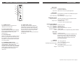
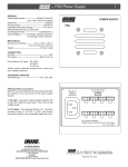
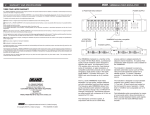
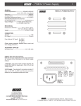
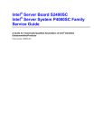
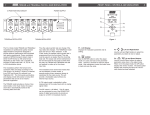
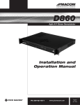
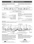
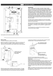
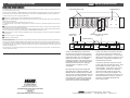
8
WARRANTY AND SPECIFICATIONS
®
MMTS20 STEREO ENCODER
1
THREE YEAR LIMITED WARRANTY
R.L. DRAKE COMPANY warrants to the original purchaser this product shall be free from defects in material or workmanship for three (3)
years from the date of original purchase.
12 POSITION RACK UNIT
POWER SUPPLY
During the warranty period the R.L. DRAKE COMPANY or an authorized Drake service facility will provide, free of charge, both parts and
labor necessary to correct defects in material and workmanship. At its option, R.L. DRAKE COMPANY may replace a defective unit.
To obtain such warranty service, the original purchaser must:
POWER SUPPLY
(1) Retain invoice or original proof of purchase to establish the start of the warranty period.
(2) Notify the R.L. DRAKE COMPANY or the nearest authorized service facility, as soon as possible after discovery of a possible defect,
of:
(a) the model and serial number,
(b) the identity of the seller and the approximate date of purchase; and
(c) A detailed description of the problem, including details on the electrical connection to associated equipment and the list of such
equipment.
AUDIO
AUDIO
AUDIO
AUDIO
AUDIO
AUDIO
AUDIO
AUDIO
VIDEO
VIDEO
VIDEO
VIDEO
VIDEO
VIDEO
VIDEO
VIDEO
PWR
PWR
PWR
PWR
PWR
PWR
PWR
PWR
A/V
A/V
A/V
A/V
A/V
A/V
A/V
A/V
AUDIO
AUD IO
MMTS20
VIDEO
AUDIO
STEREO
ENCODER
VIDEO
PWR
POWER
#
#
CH
#
CH
#
CH
RF
RF
#
CH
RF
#
CH
#
CH
RF
#
CH
RF
RF
CH
CH
RF
ON
OF F
RF
A/V
PWR
PILOT
LOCK
#
#
A/V
TEST
TONE
CH
#
OVERMOD
RF
CH
RF
(3) Deliver the product to the R.L. DRAKE COMPANY or the nearest authorized service facility, or ship the same in its original container
or equivalent, fully insured and shipping charges prepaid.
AUDIO LEVEL
Correct maintenance, repair, and use are necessary to obtain proper performance from this product. Therefore carefully read the Instruction
Manual. This warranty does not apply to any defect that R.L. DRAKE COMPANY determines is due to:
(1) Improper maintenance or repair, including the installation of parts or accessories that do not conform to the quality and specifications
of the original parts.
(2) Misuse, abuse, neglect or improper installation.
OR
4 POSITION
RACK UNIT
MMTS20 and other compatible
modular units
(3) Accidental or intentional damage.
OVERMOD
PILOT
LOCK
AUDIO LEVEL
OFF
POWER
TEST
TONE
ON
MMTS20
STEREO
ENCODER
OVERMOD
PILOT
LOCK
AUDIO LEVEL
OFF
POWER
TEST
TONE
ON
MMTS20
STEREO
ENCODER
OVERMOD
PILOT
LOCK
AUDIO LEVEL
OFF
POWER
TEST
TONE
ON
MMTS20
OVERMOD
PILOT
LOCK
AUDIO LEVEL
OFF
POWER
TEST
TONE
ON
MMTS20
STEREO
ENCODER
The foregoing constitutes R.L. DRAKE COMPANY’S entire obligation with respect to this product, and the original purchaser shall have no
other remedy and no claim for incidental or consequential damages, losses or expenses. Some states do not allow limitations on how long
an implied warranty lasts or do not allow the exclusions or limitation of incidental or consequential damages, so the above limitation and
exclusion may not apply to you.
STEREO
ENCODER
POWER SUPPLY
All implied warranties, if any, including warranties of merchantability and fitness for a particular purpose, terminate three (3) years from the
date of the original purchase.
RMM4
This warranty gives you specific legal rights and you may also have other rights which vary from state to state. This warranty shall be
construed under the laws of Ohio.
The R.L. Drake MMTS20 is an MTS stereo
encoder which accepts left and right channel
audio input and generates a composite BTSC
format stereo signal. The composite signal is
applied to the audio input of a compatible
audio/video modulator. The modular design of
the MMTS20 permits convenient pairing with a
Drake Mini-rack fixed channel or agile type
Video Modulator in a multiple unit rack
configuration.
Rear panel left and right audio inputs allow
either balanced or unbalanced operation. The
MMTS20 must be supplied with the modulator
video in order to provide the MMTS20 with sync
information for the encoding process. A front
panel Audio Level control with corresponding
Overmodulation indicator permits setting the
proper audio input levels to the MMTS20.
A Pilot Lock indicator is provided to verify that
the encoder is properly synchronized to the
supplied video horizontal sync. A built-in audio
test tone generator, turned on or off from a front
panel switch, is provided for calibration of the
modulator Audio Input level.
As previously described, front panel controls
include Audio Level and Test Tone switch. Front
panel indicators are Power, Pilot Lock, and
Overmodulation. A rear panel 'F' type connector is provided for the video sync reference.
Left and right audio inputs are through rear
panel 3.5 mm 'stereo' type receptacles. The
composite BTSC signal output is through a rear
panel RCA type phono connector. The unit is
powered by a compatible Drake Mini-rack
power supply module.
®
R.L. DRAKE COMPANY
230 INDUSTRIAL DRIVE
FRANKLIN, OHIO 45005 U.S.A.
CUSTOMER SERVICE AND PARTS TELEPHONE:
+1 (937) 746-6990
TELEFAX:
+1 (937) 743-4576
WORLD WIDE WEB SITE: http://www.rldrake.com
® is a registered trademark of the R.L. Drake Company
© Copyright 2001 R.L. Drake Company
P/N: 3852478D-10-2001
Printed in U.S.A.
2
FRONT PANEL CONTROLS and INDICATORS
F1
7
MMTS20
F2
STEREO
ENCODER
POWER
F3
PILOT
LOCK
F4
SPECIFICATIONS
ON
OFF
TEST
TONE
OVERMOD
F5
AUDIO LEVEL
Figure 1
F1 - POWER Indicator
Lights when the unit is connected to the
required source of DC power.
F2 - PILOT LOCK Indicator
Lights to indicate that a video signal is applied
to the rear panel VIDEO INPUT connector and
that the MMTS20 is locked to the video
horizontal sync.
F3 - TEST TONE Switch
Switch to the 'ON' position to enable an internal
test tone to aid system audio level setup. See
the 'Installation' section of this manual for setup
information. The normal position of this switch
is the 'OFF' position.
F4 - OVERMODULATION Indicator
Lights to indicate greater than 25 kHz of main
channel deviation. After system audio
modulation levels are properly set, and with left
and right audio source input, adjust the AUDIO
LEVEL control (see item F5) to a point where
the OVERMODULATION indicator just
remains off.
F5 - AUDIO LEVEL Control
The setting of this screwdriver adjustment
determines the audio input signal level. After
system audio modulation levels are properly
set, and with left and right audio signals within
the 250 mVrms to 2.5 V rms range, set this
control to a point where the
OVERMODULATION indicator just remains off
(see item F4).
AUDIO INPUT
Input Impedance: 40 K Ohms balanced,
20 K Ohms unbalanced.
Input Level: 250 mVrms to 2.5 V, front panel adjustment.
VIDEO INPUT
Input Impedance: High impedance, intended to be paralleled with paired
A/V modulator unit.
Input Level Range: Input Level Range: 0.5 Vp-p to 2 Vp-p.
COMPOSITE OUTPUT
Output Impedance: 100 Ohms, intended to drive high impedance audio
input of paired A/V modulator.
Output Level: 10 mV/kHz, ±10%.
1.1 Vp-p for a 100% modulation signal.
STEREO PERFORMANCE
Stereo Separation:
Total Harmonic Distortion:
S/N Ratio:
Frequency Response:
Spurious Subcarrier:
NOTE:
Greater than 20 dB.
Less than .25%.
Greater than 65 dB.
Within ±1 dB from 40 Hz to 12.5 kHz.
-50 dBc typical.
System performance is dependant upon paired modulator.
TEST TONE
Frequency: 10.396 kHz ±50 Hz.
Amplitude: 0.5 Vp-p ±10%; all output levels are calibrated to the
level of this tone and is used to set system audio
levels for proper stereo operation. The paired A/V
modulator audio response must be set for “Flat”
(pre-emphasis defeated).
GENERAL
DC Power Input: +12 V ±5% @ 150 mA
(+5 V is not required for this unit).
Operating Temperature Range: 00 C to +500 C ambient.
Size: 1” W x 3.5” H x 7.5” D
(2.5 cm) W x (8.9 cm) H x (19.1 cm) D.
Weight: 10.7 oz. (0.3 Kg).
Specifications subject to change without notice or obligation.
6
INSTALLATION - AUDIO LEVEL SETTING, continued
4) Set the MMTS20 'TEST TONE' switch to the
'OFF' position. Connect Left and Right audio
source signals to the MMTS20.
REAR PANEL CONNECTIONS / INTERNAL JUMPERS
3
The system audio levels are now properly set.
Disconnect the test equipment.
R1
5) Set the 'Audio LEVEL' control on the
MMTS20 to a point where the
'OVERMODULATION' indicator just remains off
or flashes occasionally.
R2
R3
METHOD 2: (If a spectrum analyzer is not
available).
1) Connect the MMTS20, A/V modulator,
compatible DC power source, and video source
signal as shown on this page. Keep the 'TEST
TONE' switch 'OFF' for this procedure.
2) Connect a TV receiver (with MTS stereo
capability) to the A/V modulator. Tune the TV
receiver to the same channel as the modulator
output.
3) Connect the audio source signal (not a tone)
to either the LEFT or the RIGHT Audio Input of
the MMTS20.
4) Set the 'Audio LEVEL' control on the
MMTS20 to a point where the
'OVERMODULATION' indicator just remains off
or flashes occasionally.
5) While monitoring the opposite audio channel
from the TV receiver audio output, set the
'Audio' level control on the A/V modulator for a
maximum (stereo) separation condition.
NOTE: Make certain that the audio response of
the A/V modulator is set for 'FLAT'
(pre-emphasis defeated).
MMTS20
Video Input
Loop-Through
PILOT
LOCK
ON
OFF
TEST
TONE
Video Input
Audio
Cable
POWER
Composite
Audio Out
Audio Input
DC Input
DC Input
OVERMOD
AUDIO LEVEL
MMTS20 FRONT
Audio
In
MMTS20 REAR
Right audio source
Left audio source
(250 mV rms to 2.5 V rms)
Figure 2
R1 - VIDEO INPUT Connector
This is the baseband video input to the
MMTS20 which provides the encoder circuitry
with the modulator horizontal sync information.
The baseband video to the modulator must be
'looped through' this input using an external 'F'
type Tee (T) connector.
R2 - COMPOSITE AUDIO OUT Connector
This is the unbalanced composite BTSC format
stereo signal output. The output from this RCA
phono receptacle must be connected to the
AUDIO INPUT of the modulator. The connected
modulator audio response must be set for 'Flat'
(pre-emphasis defeated).
Video Source
STEREO
ENCODER
R4
To
System Distribution
or
A/V MODULATOR TV Receiver
R3 - DC INPUT Connector
This 3-pin connector (Male) accepts the
appropriate mating DC power cable. Observe
proper orientation and wiring.
R4 - LEFT AUDIO INPUT/RIGHT AUDIO
INPUT Connectors
These are the left and right audio source input
connectors that accept either a balanced or
unbalanced configuration. Use the Tip (+) and
Ring (-) of a mating male 3.5 mm ‘stereo’ plug
for a balanced connection. If an unbalanced
input is required, the Ring (-) contact should be
connected to ground (shield) with the audio hot
connected to the Tip (+).
4
INSTALLATION - AUDIO LEVEL SETTINGS
INSTALLATION
CONNECTIONS AND CONTROLS
All connections to and from each modulator
are made through the rear panel. Figure 3
illustrates an installation with (11) modulator
units combined through a passive signal
combiner. Additional channels can be added
by using additional fixed channel or agile type
modulators and either multi-port combiners or
combinations of two-port combiners.
maintain a ±1 dB variation of adjacent channel
carriers. Aural/Visual (A/V) ratios should be
held to -15 dB or less. The output ‘RF’ and ‘A/V
(Ratio)’ controls are used respectively to make
these adjustments.
RACK MOUNTING
Adequate ventilation is very important in
multichannel installations. Some air movement
is mandatory in enclosed rack cabinets.
Excessive heat will shorten component life and
modulator performance will be degraded without
proper cooling.
INSTALLATION NOTES
Level adjustment provides optimum
performance in multichannel installations.
The modulator outputs should be checked
periodically with a spectrum analyzer to
Make certain that the audio response of the A/V
modulator is set for 'FLAT' (pre-emphasis
defeated).
Video Source
Video Input
Loop-Through
VIDEO INPUT
Audio
Cable
Composite
Audio Out
To Video Input of
Video Modulator
MMTS20
AUDIO IN
STEREO
RIGHT LEFT ENCODER
METHOD 1:
Connect the MMTS20, Audio/Video Modulator,
compatible DC power source, video source
signal and test equipment as shown.
5
MODULATOR UNIT
(Fixed channel and/or Agile type audio response set for "Flat")
To Video Input
of MMTS20
SPECTRUM
ANALYZER
DC Input
DC Input
Left Audio In
Coaxial Cable
Right Audio In
MMTS20
REAR PANEL
A/V
MODULATOR
1) Set the 'Test Tone' switch on the front panel
of the MMTS20 to the 'ON' position.
PILOT
LOCK
ON
OFF
AC POWER
CORD
TEST
TONE
2) Using the connected spectrum analyzer, tune
the aural carrier to the center of the screen.
Spectrum Analyzer Settings:
SPAN: 100 kHz.
Res BW: 1 kHz.
SWEEP: 300 mSec.
VBW: 1 kHz.
DC POWER
CABLE
3) Adjust the 'Audio Level' control on the front
panel of the connected A/V modulator for a
setting that nulls the aural carrier. If more than
one null is found, use the lowest audio gain
setting that produces a null of the aural carrier.
MODULATOR
AUDIO
VIDEO
Aural Carrier Null
RF COMBINER
SYSTEM OUT
Figure 3
Aural Carrier Centered