1
mnmnomo
AIPOS
USER'S
MANUAL
DEC-12-SQlA-D
AI P0 S
u s E R s MA NUA L
I
For additional copies, order No. DEC-12-SQlA-D from Program Library,
Price
$5.00
Digital Equipment Corporation, Maynard, Mass. 01754
First Printing, May 1971
Your attention is invited to the last two pages
of this document. The "How to Obtain Software
Information" page tells you how to keep up-todate with DEC's software. The "Reader's Comments"
page, when filled in and mailed, is beneficial to
both you and DEC; all comments received are
acknowledged and are considered when documenting
subsequent manuals.
Copyright
©
1971
by Digital Equipment Corporation
The information in this manual is for
information purposes and is subject to
change without notice.
The following are trademarks of Digital Equipment Corporation, Maynard, Massachusetts:
DEC
PDP
FLIP CHIP
FOCAL
DIGITAL
COMPUTER LAB
OMNIBUS
UNIBUS
ii
PREFACE
The PDP-12 laboratory computer is prominent as a powerful assistant to
scientific research.
Now, as the PDP-12 LOP system, a complete, total-
ly integrated data acquisition and manipulation facility is available
for both low- and high-speed laboratory instruments.
This manual de-
tails the operation of the software for the LOP system, AIPOS.
Chapter 1 includes a full explanation of the operation of the scope
assisted function loader (Job Control) , including optimization of
available mass storage devices.
All of the mathematical and display
manipulation facilities for data files are described with examples of
each command in Chapter 2 for the Display Oriented Research Analysis
(DORA) program. Because of their similarity of operation, all the file
handling functions are discussed in Chapter 3.
all sections of the manual.
Examples are included in
The Appendices provide quick reference for
loading procedures and command and error message summaries for all AIPOS
users.
A sequence of photographic examples of scope display can be
found in Appendix C.
For the experienced programmer who wishes to cus-
tomize the LOP system, a series of internal descriptions are available
(DEC-12-URlA-D through DEC-12-URSA-D).
Consult the glossary in the
back of this manual for definitions of new terms.
Additional information on the PDP-12 computer, its operation, and programming terminology and techniques can be found in the PDP-12 System
Reference Manual, DEC-12-SRZA-D, and the LAP6-DIAL Programmer's Reference Manual, DEC-12-SE2D-D.
iii
CONTENTS
Page
ix
INTRODUCTION
USING THE LDP SYSTEM
1-1
1.1
SYSTEM FUNcrIONS
1-1
1. 2
HARDWARE REQUIREMENTS
1-1
1. 3
JOB CONTROL
1-1
1. 4
MNEMONIC UNIT CODES
1-2
1. 5
CALLING A SYSTEM FUNCTION
1-3
1. 6
DEFAULT UNITS
1-5
1. 7
RETURNING TO JOB CONTROL OR DIAL
1-7
CHAPTER 1
CHAPTER 2
DISPLAY ORIENTED RESEARCH ANALYSIS
2-1
2.1
DORA'S CAPABILITIES
2-1
2.2
COMMAND FORMAT
2-1
2.3
WORKING AREA ASSIGNMENT
2-1
2.4
USE OF THE DISPLAY SCOPE
2-3
2.4.1
Data Display
2-4
2.4.2
Moving the Displays
2-5
2.4.3
Use of Cursors
2-6
2.5
CURSOR COMMANDS
2-8
2.5.1
ASSIGN CURSORS
2-8
2.5.2
FREE CURSORS
2-9
2.5.3
FIX CURSORS
2-9
2.6
FILE MANIPULATION COMMANDS
2-9
2.6.1
MOVE
2-9
2.6.2
SAVE
2-11
2.7
TYPES OF MATH COMMANDS
2-12
2. 8
UNARY COMMANDS
2-13
2. 8 .1
OFFSET Y-AXIS
2-13
2.8.2
CALIBRATE X-AXIS
2-15
2.8.3
CALIBRATE Y-AXIS
2-16
2.8.4
SCALE
2-17
2.8.5
STRIP BASELINE
2-17
2.8.6
STRIP PEAK
2-18
2.8.7
NORMALIZE
2-19
2.8.8
INTEGRATE
2-19
2.8.9
DIFFERENTIATE
2-20
v
CONTENTS
Page
2.8.10
2.9
SMOOTH
2-21
BINARY COMM.ANDS
2-21
2.9.1
ADD
2-21
2.9.2
SUBTRACT
2-21
2.9.3
INVERSE SUBTRACTION
2-22
2.9.4
OFFSET X-AXIS
2-22
DISPLAY COMMANDS
2-22
2.10
2.10.1
VIEW
2-22
2.10.2
INVERT DISPLAY
2-23
2.10.3
PLOT
2-24
CHAPTER 3
FILE HANDLING FUNCTIONS
3-1
3.1
FILE MANIPULATIONS
3-1
3.2
DATA FORMATS
3-1
3.3
FUNCTION CALL FORMAT
3-2
3.4
THE FUNCTIONS
3-4
3.4.1
MOVE
3-4
3.4.2
TRANSFER
3-4
3.4.3
PRINT
3-5
3.4.4
DISPLAY HEADER
3-5
3.4.5
FIX HEADER
3-6
3.4.6
INTERPOLATE
3-6
3.4.7
CREATE
3-7
FOCAL.12
4-1
4.1
USING FOCAL.12
4-1
4.2
LOADING FOCAL. 12
4-1
4. 3
FOCAL.12 vs. FOCAL-12
4-1
SUMMARIES
A-1
STARTING PROCEDURES
A-1
CHAPTER 4
APPENDIX A
A.l
A.1.1
LINCtape
A-1
A.1.2
Disk
A-1
A. 2
DORA COMMANDS
A-2
A. 3
LEGAL CHARACTERS
A-3
A. 4
USING INIT
A-4
vi
CONTENTS
Page
ERROR MESSAGES
B-1
B.l
J°OB CONTROL
B-1
B.2
DISPLAY INDEX
B-2
B.3
MONITOR
B-2
B.4
DORA
B-3
B.5
FILE HANDLING FUNCTIONS
B-4
B.6
BUILD/IN IT
B-4
EXAMPLES OF DISPLAY FRAMES
C-1
APPENDIX B
APPENDIX C
vii
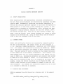
INTRODUCTION
AIPOS is the comprehensive operating system used on the PDP-12/40 and
larger systems for real-time data acquisition and manipulation in the
laboratory.
It provides a convenient structure and common data base
for a wide variety of functions, while retaining a simplicity and ease
of use which makes it the perfect solution to the problem of effective
usage of the computer in the laboratory.
The Job Control Language processor, referred to as JCL, provides a
powerful link between the user and the various functions of the system.
Aided by the highly interactive display, the user is guided through
the specification of function requests, including input and output
files, and function-qualification parameters.
His function request
is analyzed as he types it, thus reducing his waiting time, and permitting the dynamic detection and correction of errors.
AIPOS offers a complete set of data acquisition, data manipulation,
and file handling functions.
In addition, its modularity and flexi-
bility allow AIPOS to be extended to reflect the state of the art in
laboratory data acquisition, as well as the needs of highly specialized
users.
ix
CHAPTER 1
USING THE LDP SYSTEM
1.1
SYSTEM FUNCTIONS
The many capabilities of AIPOS are grouped in units referred to as system functions.
The eight system functions which provide all data mani-
pulation and interpretation facilities are described in this manual.
Briefly, they are:
1.
DORA - Display Oriented Research Analysis - display
and math routines for viewing and manipulating acquired data.
2.
File handling functions - seven functions for manipulating stored data files.
Three other system functions are described in other manuals.
Briefly,
they are:
1. 2
1.
MIDAS - Multiple Instrument Data .A.cquisi tion System data acquisition of several instruments. simultaneously.
2.
MASH - Mass Spectrometer Data Handler - acquisition,
interpretation, and filing for low resolution mass
specs.
3.
RE-GC - Research Gas Chromatography - data acquisition
and filing for up to eight GC's simultaneously and an
off-line reporting program.
HARDWARE REQUIREMENTS
The minimum hardware required for AIPOS is:
1
PDP-12/40
AIP-12 Analytical Instrument Processor
Supported options include:
RK8 disk cartridge systems
1.3
JOB CONTROL
The AIPOS functions are called by issuing a function call command to
,Jqb
Control.
Essentially a program loader, Job Control verifies the
1Job Control can be run on a PDP-12/30.
1-1
hardware configuration, activates the requested function and initializes
the specified input and output files.
requested via Job Control.
A system function can only be
Job Control is "on the air" after AIPOS is
loaded initially {refer to Appendix A), after a CTRL/C is typed {refer
to section 1. 7) , after a DX command (refer to section 1. 8) , and af te:r
processing is complete for a system function.
3ob Control displays a series of messages to assist command input.
The
general format of a function call command is:
function
output files
input files
As the user types in each part of the function call on the Teletype-l , it
is displayed on the scope.
on the same line.
Subsequent parts of the call are displayed
Each part of the call is interpreted by Job Control
as it is typed by the user.
If an error exists in the part just entered,
an error message is displayed.
The correct sequence may then be typed
for the part in error without having to retype the whole command.
~~he
RUBOUT key can be used at any time to erase the last character typed.
A backs lash ( ' ) is echoed on the Teletype.
The RUBOUT key can be used
repeatedly to delete one additional character to the left each time it
is pressed.
The LINE FEED key can also be pressed to erase the entire
command entered so far and to start a new function call.
1.4
MNEMONIC UNIT CODES
To specify an I/O device on a system function call to Job Control, the
appropriate mnemonic code and the unit number, if needed, must be used.
The codes are:
Mnemonic
Device
LT,0-7
LINCtape units ,0-7
DK,0-3
TTY
RK8 or RK12 disk units ,0-3
Console Teletype
DSP
Display scope (output device only)
Note that these codes are always followed by a colon in a system function call (refer to section 1.5).
If a nonexistent or off-line device is requested, an indicative message
appears on the scope.
1
Teletype is the registered trademark of Teletype Corporation.
1-2
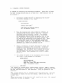
1.5
CALLING A SYSTEM FUNCTION
A command is entered by the following procedure.
(Note that at least
two mass storage devices must be on-line for a DORA function call to
be accepted. )
1.
1
Job Control always starts by displaying the following initial message on the scope:
ENTER FUNCTION
DEV:FUNCTION
DEFAULT DEV=(LT¢)
2
THEN SPACE TO SPECIFY OUTPUT,
OR = TO SPECIFY INPUT.
2.
Type the mnemonic unit code (re.fer to section 1. 4)
containing the desired system function.
Terminate
the three letter code with a colon.
For example,
LT¢ indicates that LINCtape unit ¢ is to be used.
If the default device (refer to section 1.6) is the
unit from which the function is to be loaded, then
it need not be specified in the function call. Next,
type the name of the function desired followed by
the terminator space or the terminator equal sign
if no output files are to be specified. For example,
LT¢:DORA calls DORA from LINCtape unit ~-
3.
After a terminator is typed, Job Control checks the
commands as entered so far for errors.
If any are
found, an error message indicating the problem is
displayed. Use the RUBOUT key to delete the erroneous characters and type the correct command.
(All
the Job Control error messages are listed in Appendix B .1.)
4.
If a space is typed as the terminator and no errors
are found, a new message is displayed:
ENTER OUTPUT
DEV:FILENAM.EXT
DEFAULT DEV = (LT¢)
WHEN ALL OUTPUT HAS BEEN SPECIFIED,
TYPE = TO SPECIFY INPUT
LT,0:DORA 3
1
Job Control is started after loading AIPOS, typing a CTRL/C, completing a DX command or a function job. To type CTRL/C, hold down the CTRL
key and type the letter C. The character C will be printed on the
Teletype.
2
The current default unit is displayed after the equal sign. Any time
a terminator is typed, the unit may change.
LT¢ is used only as an
example here.
3
This is the start of the function call typed by the user.
shown here is only an example.
1-3
The command
5.
The output devices and file codes are entered now
for all o~tput files that will be created by the
requested function.
The sequence DEV:FILENAM.EXT
can be repeated up to eight times, once for each
output file to be created, by separating each sequence with a comma.
Type the mnemonic unit code
(DEV), a colon, and the file name to be associated
with this file.
The file name is 1 to 6 characters
long; the first character of the file name must be
alphabetic and the file name must not already exist
on the volume. An extension code of 1 to 3 alphanumeric characters may be added optionally after
the file name and is always preceded by a period.
In the example, some output files can be created:
LT~:DORA DKl:OUTFl,LT4:0UTF2.
If the default device is the correct output device, the device and
colon need not be specified; the file names are
sufficient. No more than one output file can be
requested for each on-line device.
The extension
code with a binary file, .BIN, has special meaning
and can only be used for load files.
After the
last sequence has been entered, type as the terminator an equal sign to specify input, a semicolon to
specify parameters, or a carriage return to terminate
the function call.
6.
After each conuna and after the equal sign (or semicolon), Job Control checks for errors as in step 3.
If the RUBOUT key is used to erase the entire output
file sequence up through the space terminating the
function specification, then the initial message is
redisplayed and the function call may be reentered,
as in step 1. When the output sequence has been accepted, another message is displayed:
ENTER INPUT
DEV:FILNAM.EXT
DEFAULT DEV = (LT4)
; BEGINS PARAMETER INPUT
OR RETURN BEGINS EXECUTION
LT~:OORA
7.
DKl:OUTFl,LT4:0UTF2=
Specify the input files and devices in the same manner as the output files (refer to step 5). The example can be expanded to:
LT~:DORA
DKl:OUTFl,LT4:0UTF2=DKl:INFl,LTl:INF2,LT3:INF3
For an input file to be valid, it must be included in
the volume's index.
(Volume refers to the data on a
LINCtape or disk.)
Note that a maximum of 8 files
(input and output, including automatically allocated
working areas) can be specified in a single function
call. After all files have been entered, the function call can be terminated by typing a carriage return; the conunand is then executed.
If it is invalid,
1-4
the message in step 1 is redisplayed. Alternatively,
a semicolon can be typed, indicating that a parameter string will follow. As before, if RUBOUT was
used to delete characters through a previous terminator {equal sign or space) the previous display appears until another terminator is typed.
8.
If a semicolon is typed, the following message is
displayed:
ENTER PARAMETER STRING
ENDING WITH RETURN.
9.
Some of the AIPOS functions may require a parameter
string at the end of the function call. The format
of this string is described in the appropriate chapter of this manual.
In general, up to 32 characters
are allowed; the legal characters are listed in Appendix A.3. Terminate the parameter string by pressing RETURN; the function call is then executed.
The following examples of complete system function calls illustrate
some of the features of Job Control.
DK2:MIDAS LT3:DATAl.ASC,DKl:DATA2=LTl:SOURCE
The program MIDAS is to be called from disk unit 2 and will be used
with the output files DATAl.ASC, located on LINCtape unit 3, and
DATA2, located on disk unit 1, and the input file SOURCE located on
LINCtape unit 1.
LT~:TRANS
DKl:PHENYL=DK~:APHENYL
Call the TRANSFER function from LINCtape unit
the input file APHENYL from disk unit
~
~
and use it to transfer
to disk unit 1 where it will
be filed as PHENYL.
1.6
DEFAULT UNITS
If a device specification is omitted before a file or function name in
a function call command to Job Control, the device last accessed by
AIPOS when interpreting the command is the default unit.
The device
that is currently the default unit is displayed in all the relevant
Job Control messages so the user always knows what device will be assumed.
The unit from which the AIPOS Monitor is loaded is initially
designated as the default unit.
the initial default unit is
LT~;
Thus, for a non-disk configuration,
for a system loaded from disk, the
1-5
default unit is DK,0.
When another unit is specified, it becomes the
default unit for when a unit is not specified for a subsequent file.
Thus, if at any time in the command a device is specified, that device
becomes the default unit until another device is requested.
For ex-
ample, in the function call
DK,0:DORA FERRIC,DKl:FE26A=ETCLl,ETCL2,ETCL12
the function DORA and the output file FERRIC will be on disk unit ,0;
the other output file and all the input files will be on disk unit 1.
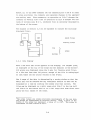
For output files, the default unit designation is more complex because
no more than one output file can exist on any device.
Thus, when speci-
fying output files without requesting a particular unit, the default
device is incremented after each file is accepted.
Even if no output
files are requested, someAC:POS programs require a minimum number of
output (working) areas, so the system will automatically assign the appropriate number of output (working) areas.
When no output device is
specified, the default load unit will contain the first output area and
the next sequential LINCtape will contain the second, etc.
For all
hardware configurations, only LINCtapes are checked for room for a
second working area; no check is made for disks.
(A Job Control as-
sembly parameter must be changed for multiple disks.)
which devices are checked is shown graphically.
The order in
The flow can be entered
at any device, but note that unless a disk is explicitly requested, it
is not accessed.
ORDER OF CHECKING
DK,0,~LT,0,LTl,
... - -
... ,LT?-,
- - -
- - -'
(after LT7, LT,0 is checked n6{t.)
For example, consider a single disk/2 LINCtape unit configuration
where the LOP system device is the disk and the command request:
DORA
NA1,NA2=NA3,NA4
The function DORA will be retrieved from DK,0.
NAl, will be created on the disk also.
The first output file,
The second output file, NA2,
will be placed on the first tape unit.
That tape unit will also be
the device checked for the two input files, NA3 and NA4.
1-6
1.7
RETURNING TO JOB CONTROL OR DIAL
Any function in AIPOS can be interrupted at any time by typing CTRL/C
which causes a return to the initial display of Job Control.
The pres-
ent operation is stopped immediately and another can be specified via
Job Control.
Note, however, that all data in the presently opened
output files is lost when CTRL/C is typed.
When Job Control (or DISPLAY INDEX) is active, CTRL/D can be typed to
exit from the AIPOS and load DIAL-MS 1 (the general purpose PDP-12 operating system.).
If the system device is LINCtape, DIAL-MS will be
loaded from tape unit
from disk.
~;
if the system device is disk, it is loaded
Be sure DIAL-MS is on the appropriate unit; if it is not,
AIPOS is restarted.
1.8
DISPLAY INDEX
In addition to the function calls, there is an auxiliary call, DISPLAY
INDEX, that can be issued to Job Control.
The file index of any mass
storage device can be displayed by typing a command to Job Control in
the format:
dev:DX
where dev is LINCtape,
LT~
to LT7, or disk,
DK~
to DK3.
The file in-
dex contains information on the entire volume of data on the device,
as well as on each file.
Information clisplayed for the volume is its
name, the starting block of the file area, and the length of the volume (number of blocks in the volume).
Information displayed for an
entry in the index is entry number (octal position in the volume) , file
name (and extension), starting block, and length of the file.
An index
header for the values is displayed as:
ENTRY
STRT
LEN
where STRT is the starting block and LEN is the length of the file in
blocks.
In general, the last file in the index is always WORK AREA
1
LAP6-DIAL-MS is referred to as DIAL-MS in this manual.
Refer to the
LAP6-DIAL Programmer's Reference Manual for information on the system.
1-7
and indicates how much space is still available (LEN) on the volume
for additional files.
The WORK AREA entry is not displayed if either
the volume or its index is full.
3;
~'
The first user file is entry number
the volume identification, the Monitor, and Job Control are entries
1, and 2, respectively.
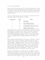
The first six entries in the index are displayed as a frame when the
index is initially called.
A different set of six index entries can
be displayed, the index can be printed, a file can be deleted or retitled, or an alias can be assigned by typing the appropriate key, as
indicated in the following table.
Key
Function
F
Move display forward 1 frame
B
Move display backward 1 frame
line feed
Move display forward 1 line
alt mode
Move display backward 1 line
L
Locate display for a file
p
Print the index on the Teletype
D
Delete a file
R
Rename a file (remove old name)
A
Create an alias for a file
return
Return to Job Control
If F is typed the next six entries in the index are displayed (or the
last six entries if there are not six more); conversely, if B is typed,
the previous six entries are displayed.
F or B can be typed as many
times as necessary to examine any section of the index.
When P is typed, the index currently displayed and header information
for the volume are printed on the Teletype.
In addition, the message
SYSTEM or NO SYSTEM is printed after the index information so that the
user will know if this is a system volume.
A specific file entry included in the index can be displayed by typing
the letter L and the name of the desired file.
A file may be deleted permanently from the volume by requesting the D
option.
To facilitate filing operations for special purposes, such as replacin9
a standard waveform, the index options Rename and Alias are provided.
1-8
When it is desired to have a new output file with the same name as an
existing file on the same unit without deleting the old file, the
name of the old file can be expanded to include an extension such as
.BAK for backup by using the Rename option.
The new file can then be
created on the same volume and checked out before deleting it in the
backup version.
If the new file is found to be incorrect, it can then
be deleted and another attempt made at creating it, or the backup version can be renamed with the correct name and used as it was initially.
The Alias feature is most commonly used for a binary program that can
perform many functions.
For example, the seven file handling functions
described in Chapter 3 use the same basic program internally; the
specific function to be performed is determined by the function name
typed in by the user in the command to Job Control.
This procedure re-
lieves the user from having to issue another command to specify the
exact function desired after having called the general program.
Thus,
using the Alias feature, one file handling proqram is called by any
one of six names (TRANS, CREATE, etc.).
If L, D, A or R is typed, the following message appears on the scope
above the index display:
ENTRY OR FILE NAME
REPLY:
Type either the number or the name (and extension) of the entry to be
manipulated as it appears in the display and press RETURN.
If this in-
dex operation is not to be performed, press RETURN alone to redisplay
the initial index display.
If L and a file name are entered, the in-
dex displayed will include that file.
If D and a file designation are
typed, the deletion is performed immediately and the initial index display reappears.
If A or R is typed, and the file designation is valid,
a new message appears above the index display:
NEW FILE NAME
REPLY:
Type the alias or the new name to be assigned to the file followed by
a carriage return.
When the operation is completed, the initial dis-
play with the modifications appears.
1-9
A carriage return is used to exit from the DISPLAY INDEX function and
return to the initial display of Job Control, incorporating all the
changes requested on the volume.
If CTRL/C is typed to return to Job
Control during an index sequence, none of the index changes entered
since requesting DISPLAY INDEX from Job Control are recorded in the
volume's index.
1-10
CHAPTER 2
DISPLAY ORIENTED RESEARCH ANALYSIS
2.1
DORA'S CAPABILITIES
After acquiring data from appropriately interfaced instrumentation,
the data files can be displayed and interpreted by requesting the AIPOS
function DORA.
Mathematical operations are executed immediately by
DORA and the resultant spectrum displayed on the scope (see Appendix C).
DORA consists of a large group of math commands that include, in part,
capabilities to integrate or differentiate a file, calibrate the axes,
straighten a sloping baseline, subtract one file from another, invert
the display and many more.
mands - math and display.
There are two main classes of DORA's comBoth classes implement two cursors to define
regions on the waveforms and a group of Sense Switch and A/D knob options to move the displayed files on the scope.
2.2
COMMAND FORMAT
DORA's math and display functions are requested by commands typed by
the user on the Teletype. The general format for these commands is
a 3 or 4 character conunand designation, a semicolon, and a file definition.
All commands are terminated by pressing the RETURN key.
RUBOUT
may be used before terminating the conunand to delete incorrect characters.
The exact syntax for each is included in the command discussion
in this chapter and in the summary in Appendix A.
Note, however, that
DORA commands which are in a format acceptable to Job Control, but illegal to DORA (e.g., unnecessary parameters} are accepted (and ignored)
by DORA and no error message is issued.
It is also possible for com-
mands that are accepted by DORA not to be accepted by Job Control.
example, illegal Job Control characters are not checked by DORA.
For
Job
Control either displays an error message or attempts to make the file
name acceptable.
All conunands are interpreted sequentially and as much
as is coherent to DORA will be executed.
2.3
WORKING AREA ASSIGNMENT
DORA is requested from Job Control by a function call in the general
form:
2-1
where outfilei is an output file and
infile~
are input
1
More than two input files can be specified in the function call,
files.
and inf ile
but DORA accepts only the first two requested.
These files must be in
floating point format; if they are not, they must be reformatted using
the AIPOS TRANSFER function (refer to section 3.4.2).
After the input files are specified to Job Control, DORA creates three
working areas, each of which initially contains a copy of one of the
original files, and which will, during processing, contain the current
version of the data files.
areas
~'
1 and T.
These areas are referred to as working
Initially, working areas 1 and T each contain a
~ contains a copy of
1
initial allocation can be considered graphically:
copy of infile
and working area
infile~.
This
input files
working areas
~
The constants
in working areas
and 1 are used in DORA commands to refer to the files
~
and 1.
Using the DORA commands, files
~
and 1 can
be modified, but the original data files are always left untouched.
Thus, working areas
nent files.
~
and 1 are temporary storage areas for the perma-
The devices that contain the working areas are derived
from the output files specification to Job Control.
If two output files
(and hence two devices) are specified, those devices will hold DORA's
working areas.
If no output file is specified, the device that will
contain the working area is as defined for default devices, section
1.6.
For system optimization, two output files should be specified,
particularly for disk configurations that are started from LINCtape,
so that Job Control is cognizant of all available devices.
Devices
that are not defined in the DORA call to Job Control or do not have a
sufficiently large working area are not used by DORA.
Working area
allocation requires that sufficient space is available on the specified (or default) devices.
If a disk is available, DORA tries to put
both working areas there rather than one on disk and one on LINCtape
for I/O optimization.
For example, the call
LT~:DORA DK~:OFl,LTl:OF2=DK~:IFl,IF2
2-2
creates working areas, if there is enough space on
DK~,
as:
If there is not sufficient room, the next working area allocation tried
is:
It is always true that an output device with a working area that is
larger than three times the size of the biggest input file plus thirty
blocks is big enough to contain all of DORA's working areas.
requires at least one working area, i.e., output device.
DORA
For I/O opti-
mization it is recommended that LINCtape users default to one output
device and specify another to Job Control.
Systems with a disk need
only default to the disk for output device specification.
2.4
USE OF THE DISPLAY SCOPE
The display scope is considered as having two parts, referred to as
top and bottom, each of which displays a data file that is contained
in the working area.
The top of the scope AlWAYS contains the file
in working area T; initially, the bottom contains the file in working
area~-
By using the MOVE command {refer to section 2.6.1) the bottom
of the scope can display the contents of working area
~
or 1.
For
ease of reference, the file displayed in the top of the scope {the contents of working area T) is called file T and the one displayed in the
bottom is referred to as file B.
area,
~
The user always knows which working
or 1, is currently being displayed in the bottom of the scope
because the appropriate number is displayed in the lower right hand
corner of the screen.
2-3
Almost all of the DORA commands use the abbreviations T and B to refer
to scope positions; the commands also generate changes in the appropriate working area.
When necessary, an operation on file T changes the
contents of working area T and an operation on file B changes the contents of working area
~
or 1, whichever file is currently displayed in
the bottom of the scope.
The diagram in section 2.3 can be expanded to include the initially
displayed files:
[J [J
input files
'V
El
IWA~I
working areas
top
bottom
2.4.1
I
scope
Data Display
When a new data file first appears on the display, its largest point
1
is displayed at the top of the scope and the smallest at the bottom •
510 points are displayed along the X axis for floating point files;
if a file has less than 510 points, enough of the file is redisplayed
so that there are 510 points visible on the X-axis.
The X range of the data is determined by a moving window so that the
whole file can be scanned and any contiguous section of data can be
displayed at a time by locating the window over that section.
The
files may be displayed on a split scope with file T in the top half
and file B in the bottom half or on a full scope with both files occupying the full length of the scope.
1
The scope values are single precision counterparts of the raw data
and should be interpreted as relative values. Thus, a point in the
middle of the scope can represent a value of 5 x 10⁶. The scope is
considered to have limits of ±377.
2-4
2.4.2
Moving the Displays
Both the top and the bottom files can be moved horizontally at any time,
and the top file can be moved vertically, but horizontal motion cannot
be concurrent.
Thus, the scope can be used to compare a modified spec-
trum with the original data or to compare an unknown spectrum with an
identified curve.
The console Sense Switches are used to define the location and direction of the motion of the spectra, as follows:
Effect
Value
Sense Switch
~
~
1
~
Full scope
Split scope
1
Fine horizontal motion
Coarse horizontal motion
1
2
~
Set horizontal motion for file T
Set horizontal motion for file B
~
Inhibit vertical motion
Enable vertical motion for file T
1
3
1
The speed at which a data file moves horizontally across the scope (the
moving window}
is controlled by A/D knob
be set properly for knob
~
~-
The Sense Switches must
to move the desired file.
Turning the
knob clockwise increases the rate of motion in the forward direction;
turning i t counterclockwise increases the rate in the reverse direction.
By centering knob
~'
horizontal movement of the display is
halted.
Knob 4 controls vertical motion of file T like a fine tuner.
The file
will move only as long as the knob is rotated .and then the display
freezes.
Knob 4 can then be rotated again to move the file another
small increment.
control, knob
~
When Sense Switch 1 is set to
also becomes a fine tuner.
~
for fine horizontal
Thus, if two spectra are
to be lined up, the recorrunended procedure is to set Sense Switches
~=~,
l=l, and 2=the file to be moved.
Then rotate knob
desired segments are almost superimposed.
Set Sense Switch
l=~
and rotate knob
~
~
until the
Use knob 4 if necessary.
to match the spectra.
As file T is being moved in any direction by a combination of Sense
Switches and A/D knobs, it will wrap around along either or both axes.
Thus, the first and last points in the file appear to be contiguous and
Y values that are moved past the upper limit of the axis appear at the
bottom of the file's display.
File B can also wrap around the X axis.
2-5
Horizontal motion of the file can produce a display, as charted above,
where point a is the last point in the file and b is the first point.
Vertical motion of file T can produce this display with vertical wraparound as the spectrum moves up (or down) the scope.
2.4.3
Use of Cursors
DORA implements two cursors on the scope, referred to as cursor
¢
and
cursor 1, which appear as intensified dots and are used to mark off areas
on the spectrum.
Initially, both cursors are associated with file T.
The X and Y coordinates of the current location on the waveform of cursor
¢
on the scope are displayed in the upper left corner of the scope
and those of cursor 1 are displayed in the lower left corner.
These
coordinates are relative scope values and are not the actual data values.
All values are signed six digit numbers and include calibrated values.
A/D knobs are used to move the cursors, as follows:
Motion
Horizontal
Vertical
¢
knob 1
knob 5
Cursor 1
knob 2
knob 6
Cursor
Rotating knob 1 or 2 clockwise moves the appropriate cursor to the
counterclockwise moves it to the left.
right.~
Similarly, for knobs 5 and 6,
clockwise rotation moves the cursor upward and counterclockwise moves it
downward.
These cursors are said to be "fixed" initially, i.e., they
can only ride along the data curve so that only the A/D knobs controlling horizontal motion are operable.
2-6
(DORA includes commands to change
the cursors' assignment.
Refer to section 2.5.1.)
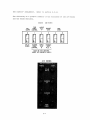
The following is a graphic summary of the functions of the A/D knobs
and the Sense Switches.
SENSE
FULL
SCOPE
FINE
HORIZ.
CONTROL
0
SWITCHES
HORIZ.
FILE
T
INHIBIT
VERT.
2
3
NOT
USED
4
5
888888
SPLIT
SCOPE
COARSE
HORIZ.
CONTROL
HORIZ.
FILE
B
ENABLE
VERT.
FILE T
MUST BE SET BEFORE
USING A/D KNOBS 0 AND 4
AID KNOBS
2-7
2.5
CURSOR COMMANDS
Cursors are either "fixed" or "free".
A fixed cursor rides along the
displayed spectrum such that only horizontal motion is permitted.
A
free cursor can move anywhere within its assigned section (top or bot-·
tom) of the scope, enabling horizontal and vertical motion.
Using the
cursor commands, the cursors can be assigned to different spectra, freed,
or fixed so that they are properly positioned for a subsequent math
command.
2.5.1
ASSIGN CURSORS
Many of DORA's math commands require one or two cursors to indicate
user chosen data points in the spectrwn.
Using the ASSIGN CURSORS com-
mand, the two available cursors may be assigned to the same spectrum
or to different spectra on the display.
The command format is:
ASCU;alpha
where alpha is T or B.
To assign both cursors to the file displayed in the top, the command is
ASCU;T
To assign both the cursors to the bottom file, the command is
ASCU;B
If the alpha parameter is omitted, cursor
cursor 1 to file B.
~
is assigned to file T and
The command is then simply
ASCU
The initial DORA display places the two cursors in the.default location:
both on file T.
If this cursor assignment is satisfactory for
the current set of data, there is no need to issue an ASSIGN CURSORS
command.
2- 8
2.5.2
FREE CURSORS
A FREE CURSORS command can be issued to free fixed cursors at any time
and is in the format:
FRCU; numeric
where numeric is
~
or 1.
If no numeric parameter is supplied, both
cursors are freed.
When a subsequent ASSIGN CURSORS command is issued, there is no change
in the
11
free 11 state of a cursor.
Thus, an ASSIGN CURSORS command in
the form
ASCU
~
associates cursor
with file T and cursor 1 with file B, and leaves
both cursors in the free state.
2.5.3
FIX CURSORS
After the cursors have been freed by a FREE CURSORS command, they may
be fixed by issuing a conunand:
FXCU;numeric
where numeric is
are fixed.
~
or 1.
If no numeric argument is typed, both cursors
Each cursor will be assigned to the point on the spectrum
with the same X value as the cursor at the time the FIX CURSORS command
is issued.
2.6
FILE MANIPULATION COMMANDS
DORA provides capabilities ·for moving displayed data files and for saving input files, permitting file manipulation facilities without having
to return to Job Control.
2.6.1
MOVE
After calling DORA from Job Control, the first input file is assigned
as file T and the second as file B and the working areas and scope are
filled
~cordingly.
At any time, these file assignments can be altered
2-9
by a MOVE command in order to compare modified data with the original
file; use a different sequence of commands on the original data file;
or display another file.
There are six data sets that can be accessed
by a MOVE corrunand.
file
~r
file B
~
file
currently displayed in top of scope and located
in working area T
currently displayed in bottom of scope and located in working area ~ or 1
file in working area
~
file 1
file in working area 1
file X
original data of the input file requested first
to Job Control
file Y
original data of the input file requested second
to Job Control.
The current content of file B is indicated by the number
played in the lower right corner of the scope.
{~
or 1) dis-
This number is the in-
put file that is currently file B and is consistent with any previous
MOVE commands.
The first input file specified to Job Control can be referred to by the
designation X in the MOVE corrunand and the second input file by the letter Y.
The constants X and Y refer to the original input files and can
not be modified by any DORA command; the designations are used only by
the MOVE command to relocate the files.
If a second input file was not
specified in the DORA function call to Job Control, Y is an illegal
parameter.
The format of the MOVE command is
MOVE;i,o
where i is the input file and is any one of the set
is the output file and is any one of the set
{~,l,T,B,X,Y}
{~,l,T,B}.
and o
Up to three
pairs can be supplied at a time and the moves will be executed sequentially.
When the output files are specified, the previous contents of
the files are replaced.
By using care in the parameter sequence of the
command, however, any file of interest can be maintained.
following examples.
MOVE;X,T,~,B
2-10
Consider the
File X, the original data for the first input file to Job Control, is
to be moved to working area T and displayed on the top of the scope
and file ~' located in working area
of the scope.
~
is to be displayed in the bottom
MOVE;~,T,l,B
This command will reverse the original DORA scope assignments.
File
~
will be displayed in the top of the scope and will be placed in working
area T; file 1 will be displayed in the bottom of the scope.
The copy
of file ~ that was placed in working area T initially is replaced during
this MOVE command.
MOVE;T,~,Y,T,l,B
A command like this one will save the file displayed in the top of the
scope by moving file T to working area
~'
input file and place it in working area T.
bring in a copy of the second
File Y will be displayed
in the top of the scope and file 1, the contents of working area 1, in
the bottom of the scope.
This is illustrated in the following chart.
D
Scope ..__ _ _-""!,_1
B
2.6.2
SAVE
Any of the data files in DORA's working areas, files
~'
1, T and B,
can be saved on LINCtape or disk for pennanent storage and subsequent
retrieval.
The SAVE command associates a name with the file and stores
the file on the mass storage device where its working area is currently
located, noting its location by a message on the Teletype.
The working
area units are those specified as output units to Job Control for the
DORA function call (or the default devices if none were specified to
Job Control).
When the SAVE command is completed, it causes a return
to Job Control.
2-11
To save a DORA file, issue a cormnand in the format
where name 1 is the alphanumeric name (in the format required by Job
Control) to be assigned to the file and p is the parameter indicatinq
1
the file to be saved in the set S,l,T or B.
For every name, a parameter must be specified.
From one to three names and parameter pairs
can be included in a SAVE command.
same device with the same name.
the sequence S,l,T is assumed.
SAVE Fl,F2,F3;S,l,T.
No two files can be saved on the
If the file parameters are omitted,
Thus, SAVE Fl,F2,F3 is equivalent to
After the S.AVE command is accepted, a message
indicating the location (unit) of the files is printed on the Teletype
in the format:
B,S,l = unit
T = unit
For example, after the conunand
SAVE SAMP1,SAMP2;1,T
a possible printout is:
B,S,l=DKl
T = LT2
The SAVE command is used to save files on LINCtape or disk; for this
reason there is generally no need to specify output files during a
DORA function call to Job Control.
Output devices need only be speci-·
fied when a particular device (e.g., a second disk) is to contain the
working areas and would not be called by the usual default device sequence.
2.7
TYPES OF MATH COMMANDS
DORA has two classes of mathematical routines:
1.
Unary - only one file is manipulated; the resultant
file replaces the displayed file on the scope and
in the working area.
2.
Binary - both displayed files (T and B) are manipulated; the resultant file always replaces file T on
the scope and in working area T.
2-12
While most math corrunands are being executed, the scope is blank and is
replaced with the resultant data display when the result has been calculated.
2.8
UNARY COMMANDS
The unary commands always require the file specification T or B; thus,
their command format is
command; alpha
where corrunand is the 3 or 4 character abbreviation for the operation
and alpha is T or B.
mands.
A cursor parameter is also used with some com-
All corrunands are terminated by a carriage return.
Any unary operation performed on file T changes that data in working
area T; any unary operation on file B changes that data in working
area
~
or 1, whichever file is displayed in the bottom of the scope.
The data in the file is changed as specified for each command.
Some of the unary corrunands require specification of a value for a
constant, K.
The acceptable range is -999,999<K<+999,999.
Decimal
6
points may be included providing accuracy of 1-i~ 10 • The values may
also be signed (±).
+3.14159
Thus~
acceptable constants include
14.0067
-3.045
96487
Note that exponential notation is illegal when specifying a constant.
For the commands requiring constants, a line feed can be typed before
the last value is supplied to abort the command and request another.
2.8.1
OFFSET Y-AXIS
The range of a displayed spectrum along the Y-axis is initially the
raw data values, but can be modified to produce a zero baseline, to
view the maxima of strong absorption peaks, or to prepare the spectrum
for a subsequent DORA command.
The amount of offset is specified by
locating one cursor at the point on the spectrum to have a Y value of
zero.
That value is subtracted from all the points in the data file.
The point where the cursor is located will have a Y-axis value of zero
in the file.
2-13
The Y-axis offset operation is specified as follows:
1.
Locate one cursor at the point on the curve to be the
zero value.
The other cursor can not be associated
with the file to be offset.
(Use an ASSIGN CURSORS
corrunand if necessary.)
2.
Issue the command in the form
OFFY;alpha
where alpha is T or B, whichever file is to be moved.
Press RETURN.
The calculation is performed and the
result displayed on the scope.
All scope displays are relative to a pair of normalization constants.
Associated with each display is a pair of MAX-MIN values either preset
(default easel or obtained from the normalization routine (NORM) .
This
pair of MAX-MIN values is used to calculate the normalization constants.
Thus, if a data file is changed and not NORMalized, it will then be
displayed using the last calculated normalization constants.
This factor
should be remembered particularly when using the OFFY command.
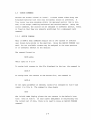
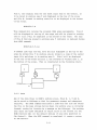
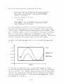
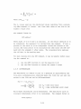
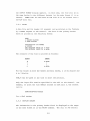
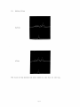
Consider a file whose MAX data value is 1.25 and whose MIN data value
is . 25.
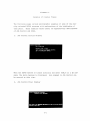
SCOPE
1. 25
1. 00
BEFORE OFFY
0.75
a.so
R
0.25
FIGURE 1
If the cursor is positioned at pt. a and an OFFY command is issued,
the new file will have a MAX data value of (1.25-.5)=.75 and a MIN data
value of (.25-.5)= -.25.
However, because the data has not been normal-
ized yet, the normalization constants have not changed and the display
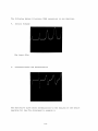
will be as shown in figure 1.
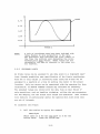
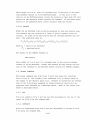
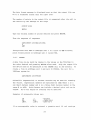
If this data is now NORMalized, it will
be displayed as in figure 2.
2-14
0.75
~------------IMm!!~----------------------~~SCOPE
a.so
Q.25
o.oo
..-.Q. 25
FIGURE 2
NOTE:
A pair of coordinate axes have been included with
these figures to give perspective to the data.
The horizontal axis indicates the point number of
the file; the vertical axis designates the corresponding file data values. These values are not
necessarily the same as observed in the scope cursor read-out.
2.8.2
CALIBRATE X-AXIS
An x-axis value can be assigned to any data point in a displayed spectrum, thereby permitting user specification of the X-axis coordinates.
From two to four values in increasing order along the X-axis can be
assigned to a spectrum at a time by setting the cursor to the proper
location.
Only one cursor can be associated with the spectrum for this
calibration; an ASSIGN CURSORS corrunand may therefore be necessary.
The assigned values are stored with the data file so that future Xaxis operations, such as baseline stripping, utilize the new parameters
for the display, but the actual data values are unaltered.
This calibra-
tion facility is particularly useful for spectra with wide areas that
are not of interest.
To calibrate the X-axis:
1.
Call the routine by typing the conunand
CALX;alpha
where alpha is T for the top curve or B for the
bottom curve.
Press the RETURN key.
2-15
2.
After the message
K=
is printed on the Teleype, rotate the cursor assigned
to the curve via its A/b knob to locate the cursor at the
desired point on the curve. The other cursor can not be
associated with the spectrum being modified. When the
cursor is correctly located, type the value to be assigned
to the x-axis at that point, followed by a carriage return.
3.
The same message, K=, is printed again so that a second
value may be assigned to the spectrum. Remember that the
x~axis values must be specified in increasing order along
the x-axis, but any value, K, can be assigned to any location in the spectrum. An error messaqe and repeated
request for the value of K will be printed if an attempt
is made to assign a value in X-axis coordinates lower
than or the same as the preceding coordinate.
4.
At least two values must be assigned for K. The message
K= is printed a maximum of four times; if less than four
values are desired, type a carriage return after the next
K= message and the calibration will be performed; if
four values are desired, the calibration will be performed after the fourth value is specified.
After a CALX operation, increments along the X-axis are not necessarily
equal.
2.8.3
CALIBRATE Y-AXIS
The Y-axis of a spectrum displayed as peaks may be calibrated for values
in the range l_::.K_::.+1,0,0, effectively making the Y-axis a percentage scale
over a user determined range.
For a spectrum displayed as dips, values
in the range -1,0,0_::.K_::.l can be used.
By permitting negative values for
inverted files, the Y minimum is always more negative than the maximum.
Only one point in the data set requires specification; the rest of the
Y values in the file are adjusted relative to the indicated value.
data in the file is not altered by a Y-axis calibration.
The
Only the value
of K is retained so the display is accurate.
The new value associated with any point can be determined using the
proportion
YD
KY a
Ye
where YD is the new value of some displayed point D; K is the value
from 1 to 100 or -100 to -1 assigned to the cursor at the original scope
ordinate value Yc ; and Ya is the scope ordinate value of the point D.
2-16
Thus, if a point is one quarter of the way up the Y scale and is assigned a value of sixty, then a point that is half way up the Y scale
50
automatically receives a value of 120, as determined by YD = 60°
.25
where percentage values are used for the half and quarter way points.
To calibrate the Y axis, proceed as follows:
1.
Type CALY;alpha
where alpha is T or B.
2.
2.8.4
After the message K= is printed, use the A/D knob associated with the cursor to locate it at the desired
point on the spectrum. The cursor can not be located
at the bottommost (-377) Y location when typing positive K values.
(The other cursor can not be associated with this curve.)
Then type in the relative
value (K in the equation above) from 1 to 100 to be
associated with this point. When the command is
executed, the only visible change in the display is
the cursor readout for the Y value.
SCALE
If the entire Y range of a set of data is too large or too small for a
useful scope display, each Y value in the file can be multiplied by a
constant, K, to bring the data into a suitable range using the SCALE
command.
The constant is specified in the same manner as the constant
for the calibrate commands; after issuing the command as
SCA; alpha
where alpha is T or B for the top or bottom spectrum, the message K=
is printed.
Type the scale factor and press RETURN.
The scaled spec-
trum is displayed in its portion of the scope and the file is altered
in its working area.
2.8.5
The other spectrum is unmodified.
STRIP BASELINE
A sloping baseline can be subtracted from any section of a data set
by placing the two scope cursors so they define the slope of the baseline to be stripped.
The line that is subtracted is the straight line
between the cursors.
The value subtracted from any Y value is the 6Y
between the cursor line and a baseline created through the lower cursor.
Note that the cursors may or may not be fixed to the curve; only the
slope of the line between them is important.
2-17
A baseline can not be
"added"; the STRIP BASELINE command only subtracts values from the
curve starting from the smaller Y value.
Remember that any previous
changes to the data by other DORA routines are considered in this calculation.
The procedure for subtracting a baseline is as follows:
1.
The cursors must be properly positioned before the
command is issued.
If a baseline is to be stripped
from all the data points, set the two cursors so they
demark a line with the desired slope.
If a baseline
is to be stripped from only a portion of the data
points, locate the two cursors so that, in addition
to creating a line with the desired slope, one is
on or above the first point in the baseline to be
altered and the other is similarly located for the
last point.
2.
Call the routine by typing:
BLS;alpha,C
where alpha is T or B, and C is optional; if the
baseline indicated by the two cursors is to be subtracted only from those points between the cursors,
then the argument C is required in the command.
If
that baseline is to be subtracted from all the data
points, the argument C is omitted.
2.8.6
STRIP PEAK
A peak or any section of a spectrum can be stripped from the data and
replaced by a linear data set using the PEAK STRIP command.
The cur-
sors are located on the curve to indicate the region to be replaced and
may include any displayed region of the spectrum.
The peaks are stripped
between the cursors from the lower X value to the higher X value.
An unlimited number of peaks can be removed; each will result in the
straight line formed between the cursors replacing the data.
Because
both cursors must be on the same curve before issuing the command, an
ASSIGN CURSORS statement may be necessary.
If a CALX operation has al-
ready been performed on that part of the data to be peak stripped, then
two connecting lines with different slopes may replace the peak.
procedure to strip out a section of data is:
1.
Locate the cursors on the curve so they mark the
beginning and end of the data to be replaced by
a straight line with the slope indicated by the
cursors.
2-18
The
2.
Type the command as:
PKS;alpha
where alpha is T or B for the curve to be peak
stripped.
2•8•7
NORMALIZE
When DORA displays a set of data after some mathematical operations,
the points that are larger than the scope limits of ±377 appear at the
top of the scope with no definition of the large peaks.
smaller peaks may not be sufficiently resolved.
Also, the
The NORMALIZE command
performs two functions:
1.
Brings the entire file within scope limits.
2.
Enlarges the file so that user's specified maximum and minimum points are the scope Y-axis limits.
(This function requires that both cursors be assigned to the spectrum.)
NORMALIZE does not change the data in the working area.
Instead, the
necessary constants are stored with the data so that the file displayed
after other cormnands includes the effect of the NORMALIZE command,
leaving the actual data unaltered.
To normalize the entire file to scope limits, issue the command as
NORM; alpha
where alpha is T or B for the file to be normalized.
The second function enlarges small peaks by normalizing them to the
scope limits.
Position the cursors so that one defines the Y-axis
minima and the other the Y-axis maxima and type the command as
NORM;alpha,C
The entire file is enlarged and Y values that are larger than +377
appear as points at the top of the scope and those smaller than -377
appear as points at the bottom.
2.8.8
INTEGRATE
An integration can be performed for a displayed spectrum that uses the
algorithm:
2-19
The X.i
values used are the calibrated values resulting from a preced-
ing CALX conunand, if issued.
signed a value of
The first data value of the file is as-
~-
The command format is:
INT;alpha,C
where alpha is T or B and C is optional.
If the entire spectrum is to
be integrated, the argument C is omitted from the conunand.
If only a
portion of the curve is to be integrated, locate the cursors at the
initial and final points to be calculated and then issue the INT command with the argument C after alpha.
The integrated data replaces
the old data in the working area.
For best results with the INT conunand, it may be helpful before issuing the command to:
2.8.9
~
1.
use the OFFY function to set the baseline to
2.
use the CALX function to assign the proper X range
DIFFERENTIATE
The derivative of a whole or part of a spectrum is calculated by the
five point differentiation algorithm where the first two and last two
points in the file can not be differentiated:
For F = {(X.,F(X.))}
l
l
D'F=6.Y
6.X
for Y
some data value
for X
some calibrated point count
n
n
Multi-depth derivatives can be determined.
The derivative curve is
displayed inunediately after it is calculated.
DIFF;alpha,C
2-20
The command format is
where alpha is T or B, and C is included only if the part of the spectrum between cursors is to be differentiated.
If only part of the
curve is to be differentiated, locate the cursors so they mark off that
portion of the spectrum before .issuing the command.
If the whole spec-
trum is to be differentiated, cursor location does not matter.
2.8.10
SMOOTH
Noise can be smoothed from an entire spectrum or from the portion that
lies between the two cursors by a.least (7 point) squares curve fit
routine.
sors.
At least seven data points must be included between the cur-
The algorithm used is:
where Y. =point to be smoothed
.1.
Y'. = smoothed point
1.
The format of the SMOOTH command is
SMO; alpha, C
where alpha is T or B and C is included only if the portion between
cursors is to be smoothed.
Locate the cursors so they denote the por-
tion of the waveform to be smoothed before issuing the SMOOTH command.
2.9
BINARY COMMANDS
The binary commands use both files T and B and place the resultant
data in file T.
The length of the resultant file is always equal to
the length of the shorter input file.
Because no parameters are needed,
each of the four binary commands is issued simply by typing the appropriate code followed by a carriage return.
Each of the binary com-
mands is described below.
2.9.1
ADD
File B is added to file T and the sum file displayed in the top of the
scope (as file T) by the command ADD.
2.9.2
SUBTRACT
File B is subtracted from file T and the difference is placed in file
T by using the command SUB.
2-21
2.9.3
INVERSE SUBTRACTION
The SUBTRACT operation can be reversed via the ISB command; file T is
subtracted from file B and the difference is placed in file T by the
inverse subtraction routine.
2.9.4
OFFSET X-AXIS
When two spectra are displayed at the same time, an OFFSET X-AXIS command can be issued to line up any two points on each spectra, so that
the spectra have conunon X-axis values.
The cursors are used, one on
each spectrum, to determine the corresponding points.
When the com-
mand is executed, the file with more points to the left of the cursor
location has sufficient points deleted from its start so that the two
x-axis values coincide.
To offset the X-axis, locate the cursors at the X locations that are
to correspond with each other, one on each curve, and type the command
OFFX.
Note that the resultant file must be at least one block long or
the files can not be offset.
2.10
DISPLAY COMMANDS
In addition to the math routines, DORA implements several commands to
maximize scope interaction which can be issued to invert the spectrum,
remove a spectrum from the scope or generate a hard copy on an interfaced X-Y plotter.
These corranands are called in the standard DORA
format.
2.10.1
VIEW
At any time while using DORA, a single file can be viewed on the scope.
If only one file is currently displayed, the VIEW command re-enables
the inactive display.
The format of the VIEW command is:
VIEW;alpha
where alpha is T or B for the file to be displayed.
value can be specified.
Only one alpha
If no parameters are entered after VIEW, then
any file not currently displayed because of a previous VIEW command is
redisplayed.
2-22
2.10.2
INVERT DISPLAY
A spectrum displayed on the scope can be inverted (peaks to dips and
vice versa) and its complement displayed.
performed on the inverted file.
on the inverted file.
Math commands can then be
One or two spectra can be polarized
One or two spectra can be polarized by a state-
ment in the form
INVR;alpha
where alpha is T or B.
To invert both displayed files, the command is
INVR;T,B
An INVERT command issued without any parameters returns all displayed
files to their original state (peaks or dips).
(If both parameters are
the same, e.g., INVR;T,T, no effective operation is performed.)
The INVR command leaves the baseline invariant for both full and split
scope, i.e., points that are displayed at the bottom or middle of the
scope are never inverted:
BEFORE'
INVR
*NOT INVERTED
Users who would like a real INVR can always scale by -1 with the realization that the original data was modified.
2-23
Note that if the scope is inverted prior to a MOVE command, it remains
inverted after the command.
In general, the INVR command is invariant
with the MOVE command.
2.10.3
PLOT
The PLOT command can be used to print up to six line plots of any displayed spectrum on an interfaced X-Y plotter permitting multiple plots
of a file.
When a PLOT command is issued, the scope is cleared.
At
this time, turn the plotter to start; plotting is then initialized by
typing any key on the Teletype (not including CTRL/C or RUBOUT) and a
moving dot traces across the scope.
scope is again cleared.
When the plot is completed, the
Turn off the plotter, then type a key.
the display reappears, another DORA operation can be requested.
To generate line plots:
1.
Request all math and display operations so that the
file on the screen is exactly the plot desired.
2.
Up to six plots can be requested for either displayed
file or any combination of them. The plots will be
drawn in the order in which they are specified in the
command. The format is:
PLOT;alpha,alpha,alpha,alpha,alpha,alpha
where any one alpha is T or B. Specify the PLOT command with 1 to 6 alpha parameters and press RETURN.
(If no parameters are specified, file T then file B
are plotted.)
3.
When the screen becomes blank, turn the plotter on,
then type a key on the Teletype.
4.
During plotting a moving dot traces across the scope.
Turn the plotter off; then type a key on the Teletype.
The display will reappear.
5.
If more than one file is being plotted, an additional Teletype key must be typed between the plots (i.e.,
a total of 2 keys) ; one to terminate the current plot
and one to initiate the next plot.
2-24
When
CHAPTER 3
FILE HANDLING FUNCTIONS
3.1
FILE MANIPULATIONS
AIPOS includes extensive file handling facilities that are implemented
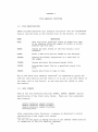
usinq a one word code in the function call to Job Control, as follows:
Operation
Code
MOVE
Move data files specified either by AIPOS file name
or by starting block and number of blocks or points
between tape and disk.
TRANS
Change the data format of the file during a file
transfer.
PRINT
Print a data file and its header on the Teletype.
DISHDR
Display the header information of a data file on
the scope.
FIXHDR
Create and store the primary header block.
IN TERP
Interpolate input file to a specified output file
size.
CREATE
Create data files on tape or disk.
Any of the seven file handling functions 1 is requested by typing the
code for that function and the files it is to use in the same manner as
any other call to Job Control, at any time when the system is under
Job Control.
3.2
DATA FORMATS
Some of the file handling functions
(TRANS, INTERP, CREATE) require
specification of the file's data format.
There are four acceptable
data formats:
single precision signed integers
double precision signed integers
double precision signed fractions
floating point
After requesting those functions, a message is displayed to permit
specification of the output file format:
1
Do not use the Alias or Rename feature of the DISPLAY INDEX function
to rename any of the file handling commands.
3-1
OUTPUT FORMAT
1
S.P.
D.P.
D.P.
FLT.
2
3
4
REPLY
INT.
INT.
FRAC.
PT.
The format is specified by typing the appropriate number (1-4) and pressing RETURN.
played.
A reply other than 1 to 4 causes the message to be redis-
An input file that is not an AIPOS file also requires
specification.
format
For that purpose, the above message is displayed with
the header INPUT FORMAT and is answered in the same manner as the output format messages.
It is possible to change the format of a file by using the TRANS function.
It should be noted however that each format has its own charac-
teristics; therefore numbers which may be represented in one format may
be nonexistent in another.
For example, the floating point number 3.5
is a 3 in double precision integer format.
In general, any file may be
converted to floating point format without losing any precision.
When
changing the format of a file, values in the input file that are out of
the range of the output file are set to the closest limit of the format
of the output file.
-2~48
-.999999
-.838861 x 1~7
3.3
The format ranges used:
Single precision integers
Double precision fractions
Double precision integers
2~47
+.999999
+.838861 x 1~7
FUNCTION CALL FORMAT
Each of the six file handling functions is called through Job Control
by a statement in the form:
dev:function outdev:outfile=indev:infile
The normal sequence of Job Control messages are displayed and answered
as described in section 1.5.
Default devices are determined in the
same manner as explained in section 1.5.
All of the file handling func-
tions return to Job Control after completing the requested operation.
It is possible to specify an input and/or output file by starting block
and number of blocks or points rather than by file name by simply not
including the name in the function call.
Thus, legal calls include:
dev:function outdev:outfile=indev:infile
dev:function outdev:outfile
dev:function=indev:infile
dev:function
When an input specification is omitted in a function call, the following message is displayed (after the file format message) :
3-2
INPUT
ENTER
DEV:
STARTING BLOCK,
POINTS AS Pxxxxxx
OR
BLOCKS AS Bxxx
RETURN
Note:
When input definition is required during a MOVE command, the
message is as follows:
INPUT
ENTER
DEV:
STARTING BLOCK,
BLOCKS,
RETURN
REPLY:
Three parameters must be specified. First, a mnemonic unit code is
typed followed by a colon to locate the file. The starting block number (octal} is entered next and followed by a comma.
bers are
~
to 1577 for LINCtape and
~
Legal block num-
to 6257 for disk.
is specified as number of points or number of blocks.
The file length
To indicate the
number of points, type P followed by a decimal number in the range 1
to 999,999.
1
To indicate the number of blocks, type B
octal number of blocks in the range 1 to
disk.
16~~
followed by the
for tape and 1 to
626~
If the output file name was omitted, the display is
OUTPUT
ENTER
DEV:
STARTING BLOCK,
RETURN
REPLY:
Respond to this display with the same parameter restrictions as the
INPUT display.
(There is no need to enter the number of blocks or
number of points.)
Both replies are terminated by pressing the return key.
response causes the message to be redisplayed.
1 h
. not require
. d d ur ing
.
T e B ~Ls
a MOVE comman d .
3-3
An
illegal
for
For example, to specify an input file that starts at block 2¢ on LINCtape unit 4 and is 47 blocks long, a correct reply to the input file
message is
LT4,2¢,B47
If this same file contains
3¢¢~
points, a correct reply is
Note that input data files requested in this manner are treated as if
no header block were present.
Similarly, output files are created with-
out a header block.
3.4
THE FUNCTIONS
3.4.1
MOVE
The MOVE command is used to copy files onto another tape or disk or to
duplicate the file on the same device.
To move the file LEUCO from
disk unit 2 to tape unit 2, and assign it the name ALEUCO, the call to
Job Control, assuming
LT~
is the system device, is
LT¢:MOVE LT2:ALEUCO=DK2:LEUCO
This command can also be used to copy an entire volume of data by requesting only the function from Job Control and then replying to the
input and output file displays.
For example, to copy the tape on unit
4 to unit 6, the call to Job Control and the file specifications are:
LT¢:MOVE
LT4,¢,16¢¢
LT6,¢
Note that no data format changes are possible during a MOVE command.
3.4.2
TRANSFER
In addition to moving a file between I/O devices, the TRANSFER command
changes the format of the data.
The OUTPUT FORMAT message is displayed
so that the format can be specified.
Thus, after a call to Job Control
such as
DKl:TRANS LTl:BUTAMD=LTl:BUTAMS
3-4
the OUTPUT FORMAT display appears.
In this case, the file will be on
the same device in two different formats
chosen).
(or the same format if it is
TRANS must be used when an LDP file is to be created from a
non-LDP data file.
3.4.3
PRINT
A data file and its header (if present) can be printed on the Teletype
by a PRINT request to Job Control.
The data in the primary header
block is printed in the following format:
NAME
n HEADER BLOCKS
n DATA BLOCKS
DESCRIPTION OF FORMAT
n POINTS
THE MAXIMUM VALUE IS ±.aE±b
THE MINIMUM VALUE IS :l::.aE±b
The contents of the file is printed as follows:
POINT
VALUE
±.·aE:l::b
n
:I::.
aE±b
For the values in both the header and data blocks, a is six digits and
b is 3 digits.
CTRL/C may be typed at any time to abort the printing.
Only the input file need be specified in the call to Job Control.
For
example, to print the file C6HCL5 located on disk unit 2, the correct
call is
DK~:PRINT=DK2:C6HCL5
for a disk system.
3. 4.
·~
DISPLAY HEADER
The information in the primary header block is displayed on the scope
in the same format as in the PRINT conunand.
3-5
The call to Job Control
requires specification of the input file only, so that the call
DK~:DISHDR=DK2:C6HCL5
will display the header block of the file C6HCL5 on disk unit 2.
Type
CTRL/C to return to Job Control.
3.4.5
FIX HEADER
The primary header block can be created and stored for an LDP data file
that is already present on the volume.
be a free block.
The first block of the file must
Only the data file requires specification, as the
input file, in the call to Job Control:
dev:FIXHDR=indev:infile
The data format message is then displayed for the input file.
When
that has been specified, the total number of header blocks and data
points is requested by the display:
ENTER
NUMBER OF HEADER BLOCKS
NUMBER OF DATA POINTS
HEPLY:
Type the total number of header blocks, in the range 1-7, that the
data file contains, followed by a comma.
Then type the total number of data points in the file and press RETURN.
Note that FIX HEADER computes only the primary header block.
Secondary
header blocks, if present, are the user's responsibility.
3.4.6
INTERPOLATE
An output file can be created that is an interpolated subset or superset of an input file.
INTERPOLATE can provide increased file resolu-
tion with no loss of accuracy by requesting a larger number of points
in the output file.
In addition, two spectra of the same compound that
contain a different number of points can be compared by expanding or
decreasing the number of points in one file.
The call to Job Control is in the standard format:
dev:INTERP outdev:outfile=indev:infile
3-6
The data format message is displayed next so that the output file can
be in a different format than the input file.
The number of points in the output file is requested after the call to
Job Control by the message on the scope
OUTPUT SIZE
REPLY:
Type the decimal number of points desired a.nd press RETURN.
Thus the sequence of responses
LT~:INTERP
LT3:RNA=LTl:RNA
4
2fl,0
interpolates file RNA on LINCtape unit 1 to a file of 2,0,0 floating
point format points on LINCtape unit 3 called RNA.
3.4.7
CREATE
A data file can be built by typing in the values on the Teletype in
the order desired and pressing RETURN after each.
Only the output file
and device need to be specified in the CREATE call to Job Control.
To
create a file on LINCtape unit 3 and call it PYRINE, the call for a
LINCtape system is:
LT,0:CREATE LT3:PYRINE
Scientific (exponential) or decimal notation may be used for entering
the values.
Exponential numbers are specified as aE±b where a is a
six digit decimal number and b is a three digit decimal number in the
range ,0 to ±599.
signed.
Both formats can include a decimal point and can be
Up to six digits of accuracy can be obtained.
Examples of acceptable values are:
1,0
1,0.
l,0E+l
.1
lE-1
1. ,0E-l
-1,0.5875
-.l,05875E+2
-l,05875E-4
If an unacceptable value is entered, a question mark (?) and carriage
3-7
return/line feed are echoed on the Teletype and the incorrect value is
ignored.
When all values have been entered, type CTRL/S to store
data in the specified file and return to Job Control.
3-8
thE~
CHAPTER 4
FOCAL.12
4.1
USING FOCAL.12
The AIPOS system allows its users to acquire, reformat, transfer, manipulate, and display data files.
However, most users require that more
specific tasks be performed on their data.
For this reason the AIPOS
system contains a version of FOCAL-12 (called FOCAL.12 in AIPOS) that
is capable of manipulatinq AIPOS files.
4.2
LOADING FOCAL.12
To use FOCAL.12 issue the following command to Job Control:
DEV:LOAD=DEV:FOCAL.12
When FOCAL.12 has been successfully loaded, it will respond with
*
At this time, the user may enter any of the FOCAL-12 commands as described in the PDP-12 manual FOCAL-12
4.3
(DEC-12-AJAA-D) .
FOCAL.12 vs FOCAL-12
FOCAL.12 differs from DIAL FOCAL-12 in the following ways:
All file names specified in L M, L 0, L L, and L S
commands must be in the AIPOS file name format (i.e.,
six characters followed by a character extension) .
ALIASed AIPOS files must not be replaced via L M or
L S commands.
An LDP RETURN (abbreviation L R) allows the user to
close all files and return to the AIPOS Job Control.
All AIPOS files contain a primary header block and a data area.
If a
user creates a data file using FOCAL.12 and wishes to manipulate it
using DORA or any other AIPOS function he must first create the primary
header block.
This may be accomplished with the FIXHDR command (refer
to section 3.4.5).
4-1
APPENDIX A
SUMMARIES
A.l
STARTING PROCEDURES
A.1.1
LINCtape
To start AIPOS from LINCtape:
1.
Press the STOP console switch.
indicator to 1 & 2.
Set the scope channel
2.
Mount the LDP system tape containing the Monitor and
Job Control on tape unit ~(If required, mount
another LDP system tape (or disk) on a unit 1-7 (or
1.,.. 3) •
3.
Set the tape units to REMOTE and WRITE ENABLE.
the disk on if it is being used.)
4.
Clear all the console switches.
(A switch is cleared
when the front part of the rocker is raised.)
5.
Set the Left Switches to ~7~~ by pushing down the
front part of the switches indicated by + and the
back part of the switches indicated by t in the following diagram:
(Turn
Ht +H Ht Ht
Left
Switches
6.
Press the I/O PRESET switch.
7.
Press the DO switch.
8.
Press the START
A. l . 2
2~
switch.
Disk
To start AIPOS from RKB for RK12 disk:
1.
Press the STOP console switch.
nel indicator to 1 & 2.
2.
Mount the LDP system disk containing the Monitor and
Job Control in disk unit ~If required, mount another LDP system tape or disk on a tape unit 1-7 or a
disk unit 1-3.
3.
Set the disk START switch.
If the SAFE light does
not go out in a few seconds, the disk must be remounted.
Return to step 2.
A-1
Set the scope chan-
4.
When the drive ~ light goes on, clear all the console switches.
(A switch is cleared when the front
part of the rocker is raised.)
5.
Set the mode switch to 8 mode.
6.
Set the Left Switches to ~~2~ and the Right Switches
to 6733 by pushing down the front part of the switches
indicated by ~ and the back part of the switches indicated by t in the following diagram.
Ht ttt Ht ttt
Ht +H tH tH
Left Switches
Right Switches
7.
Press the FILL switch, then press the FILL STEP switch.
8.
Set the Right Switches to 5~21.
as follows (refer to step 6):
The switches are set
+H ttt Ht tH
Right Switches
9.
Press the FILL STEP, I/O PRESET and START
in that order.
2~
switches,
If AIPOS was successfully loaded, it signals that it is ready for a
function call command by displaying the first Job Control message on
the scopeo
A command to Job Control can now be issued.
If the AIPOS tape or disk on unit
~
does not contain the AIPOS Monitor
and Job Control, NO is displayed on the scope.
Mount the correct tape
or disk and start again.
A.2
DORA COMMANDS.
Cursors
ASCU;alpha
FRCU; numeric
FXCU;numeric
Assign cursors
Free cursors
Fix cursors
MOVE;i,o
SAVEj namei ;pi
Move
Save
File
Math
Unary
OFFY;alpha
CALX;alpha
CALY;alpha
SCA; alpha
BLS; alpha ( ,C)
PKS;alpha
NORM; alpha ( ,C)
INT; alpha ( ,C)
DIFF; alpha (, C)
SMO;alpha(,C)
Off set Y-axis
Calibrate X-axis
Calibrate Y-axis
Scale
Strip baseline
Strip peak
Normalize
Integrate
Differentiate
Smooth
A-2
Binary
ADD
SUB
ISB
OFFX
Add
Subtract
Inverse subtract
Off set X-axis
Display
VIEW;alpha
INVR;alpha(,alpha)
PLOT;alpha
View
Invert display
Plot (up to six alphas)
alpha =
numeric
i = one
o = one
name.J_ =
T or B
= fa or 1
of fO, 1, T, B, X, Y
of ~, 1, T, B
filename (paired with a parameter p.)
J_
p. = one of {~, 1, T, B}
(i) = optional parameter
C = means use cursor
A. 3
LEGAL CHARACTERS
A
$
B
&
c
(
)
D
E
F
G
H
I
*
+
I
J
K
~
1
2
L
M
N
3
4
5
6
7
8
9
0
p
Q
R
s
T
u
v
w
<
x
y
>
z
[
'
]
t
?
(SHIFT/K)
(SHIFT/L)
(SHIFT/M)
@
LINE FEED
RETURN
ALT MODE
RUBOUT
CONTROL/I (TAB)
-+
SPACE
II
A-3
A.4
USING INIT
The initialization program, INIT, creates LINCtapes and disks that can
be used by the LDP system by placing the necessary index information
and the AIPOS system (Monitor and Job Control) on the tape.
To prepare
an LDP tape/disk:
1.
Start the LDP system by the appropriate procedure in
Appendix A.
2.
When the initial Job Control display appears, type
INIT and press the return key.
3.
The first display of the INIT program appears:
LDP UNIT TO INITIALIZE:
LT~-7
DK~-3
LINCTAPE
DISK
REPLY:
4.
Type the mnemonic unit code for the device containing
the volume to be initialized for the LDP system.
This
volume must be a marked LINCtape or formacted disk.
Then press the return key.
RETURN may be pressed alone
as the reply to this display to return to Job Control.
5.
When an acceptable response is typed, the next display
appears:
ENTER UP TO TEN CHARACTERS
FOR VOLUME IDENTIFICATION
REPLY:
Up to ten printing DIAL characters may be typed in for
volume identification purposes.
The information entered
this time appears as the first entry in an index display (DX).
It may be helpful to use the date created
as the volume identifier.
6.
After the volume identifier is entered and accepted,
the next display is:
HOW MANY INDEX BLOCKS SHOULD BE
ALLOCATED?
(1 TO l~ OCTAL)
DEFAULT IS 4
REPLY:
The number of index blocks to be allocated to this
volume is specified now.
This value should be large
enough to accommodate all future files because additional index blocks can only be allotted by reinit.ializing the volume, thereby losing all files currently
on the volume.
Use the following parameters as a guide
in determining the number of blocks to allocate.
A-4
32
1 ~ index entries/index block
1st index block requires 3 entries for
system use.
Each file, alias, and deletion requires an
index entry.
It is suggested that a tape
have at least four index blocks and a disk
have ten blocks.
7.
Type the number of blocks to be used for the index
and press the RETURN key.
8.
If it is a LINCtape that is being initialized, the
next display is:
HOW MANY BLOCKS ARE MARKED ON
THIS TAPE?
(1¢¢¢ TO 16¢¢ OCTAL)
DEFAULT IS 16¢¢
REPLY:
If the tape was marked (via MARK12) for 1¢¢¢ blocks,
type 1¢¢¢; if it was marked for 16~¢ blocks, type
16¢~.
Then press the return key.
If the volume
being initialized is an RK8 disk, a length of 626¢
8
blocks is assumed.
9.
The next display is:
WHERE ARE THE SYSTEM BINARIES?
LT¢-7
DK~-3
DIAL
NO
LDP TAPE
LDP DISK
DIAL-MS FILES
OMIT SYSTEM
REPLY:
If a system from another LDP volume is to be copied
onto this volume, type the mnemonic unit designation
for the device containing that volume.
If carriaqe
return alone is typed, the system will be copied
from the current system residence device.
If a new
system is to be created from DIAL-MS binary files,
type DIAL, which will cause the following display
to appear:
ENTER NAME, COMMA, AND DIAL UNIT
OF LDP MONITOR BINARY
REPLY:
•rype the DIAL name and unit of the device where the
LDP Monitor resides.
For the Monitor on LINCtape
DEC-12-SQAA-UO, the DIAL name is M¢1 (for version 1).
The unit number is as in DIAL-MS: ¢-7 for tape and
1¢-15, 2¢-25, 3¢-35 and 4¢-45 for RK8 disk.
If no
system is desired on the volume being initialized
(e.g., it is to be used for data only), type NO.
All replies are followed by RETURN.
A-5
10.
After the Monitor is copied from the specified unit
onto this volume, the following display appears:
ENTER NAME, COMMA, AND DIAL UNIT
OF LDP JOB CONTROL BINARY
REPLY:
Type the DIAL name and unit number of the device
where Job Control resides.
For the Job Control
binary on LINCtape DEC-12-SQAA-UO, the DIAL name
is JOBCTL.
After it is copied, the message in
step 3 reappears.
Another volume may then be
initialized or Job Control can be reentered.
Note that it is very poor practice to initialize the system unit because
the system may be copied to different tape blocks than it had before
initialization.
A-6
APPENDIX B
ERROR MESSAGES
All the AIPOS programs alert the user to unacceptable command input
by an error message.
B.l
These messages are listed here by system program.
JOB CONTROL
As a command is entered to Job Control, it is checked for errors after
every delimiter.
If an error is found, a message is displayed on the
scope indicating the type of error.
Generally, the errors require
specification of a different name to eliminate duplication or of
another device to provide sufficient room.
For this purpose, RUBOUT
can be used to remove the faulty characters in the command and the
correct characters can then be typed in.
delete the entire line.
Line feed can be typed to
All the messages are listed below.
REQUESTED FILE DOES NOT EXIST.
INVALID CHARACTER
OR IMPROPER SYNTAX.
PLEASE CORRECT.
NOT AN LDP VOLUME.
OUTPUT FILE ALREADY EXISTS.
INSUFFICIENT SPACE TO CREATE FILE.
INDEX IS FULL.
ONLY ONE OUTPUT FILE
ALLOWED ON ANY DEVICE.
NO MORE FILES ALLOWED.
TOO MANY CHARACTERS
IN PARAMETER STRING.
UNABLE TO SAVE name
name IS INVALID OR
DUPLICATE FILE NAME.
REPLY:
SAVE AS ?
Job Control also has a pause message which appears if a nonexistent
or off-line device is requested:
B-1
WAITING FOR device
PLEASE READY IT,
OR TYPE CONTROL/C TO RESTART
The next error message indicates insufficient room on the requested
(or default) device for the file.
A new volume is required with
enough free space.
UNABLE TO ALLOCATE WORKING AREAS.
CONTROL/C TO RESTART.
B.2
DISPLAY INDEX
After a DX error message is displayed, press RETURN to redisplay the
last index shown.
Its messages are:
SPECIFIED FILE DOES NOT EXIST.
A nonexistent file was requested.
SORRY, NEW NAME ALREADY EXISTS.
New name (after R or A) is already associated with a file.
INDEX IS FULL.
This alias request can not be filled because there is no more room in
the index of this volume.
B.3
MONITOR
Under certain conditions, the Monitor may detect programming or unrecoverable hardware errors.
on the console Teletype
should then be reloaded.
a~
In this event, an error message is printed
i t halts near location 712.
The LDP system
The errors are:
Message
Meaning
Attempt to execute an unimplemented Monitor command.
May also be caused by jumping to page zero illegally.
?l
Too many interrupt pushes: probably routine which
called INTPSH did not call INTPOP.
?2
Too many interrupt pops:
B-2
opposite of ?l.
Meaninq
Messag~
?3
Too many SETINTs. Program is setting up too many
interrupt handlers, and not deleting unused ones.
?4
Invalid I/O unit.
unit.
?5
I/O request on a busy control block. Program failed
to wait for completion of the preceding operation.
?6
Unrecoverable disk error.
B.4
I/O request for a nonexistent
DORA
DORA has its own set of error messages to indicate an illegal operation
or request that can not be completed.
The message is printed on the
Teletype as a question mark and a two digit number.
each code follows.
The meaning of
If the display has been cleared to execute the com-
mand, the display is reactivated after the error message is printed.
Code
Meanin_g_
?4~
Undefined command - illegal characters or command can
not be performed on requested file.
?41
Improper syntax - too many characters, illegal file
names or any syntax error in command.
?42
Illegal parameter string - illegal characters, string
too long or too short, or undefined file requested.
?43
Invalid command file requested is not currently visible
on scope.
?44
Cursor error - cursors positioned improperly.
?45
OFFX error - too few or too many points to move.
?46
FPP arithmetic error - number out of acceptable range.
?47
Division by zero requested - this is an illegal operation.
?48
Illegalvabe - numeric input outside of acceptable
range, or CALY cursor error.
?49
Invalid files - no input files requested or an input
file is in an illegal format (e.g., binary).
Returns
to Job Control.
?5~
Working area too small - input file does not fit in
assigned working area.
Returns to Job Control.
?51
INVR error - an operation between cursors can not be
performed on an inverted file.
?52
Vertical OFFX error - OFFX is not needed because cursors are positioned on identical file points.
B-3
B.5
FILE HANDLING FUNCTIONS
The following error messages can be printed during a file handling operation.
Code
Meaning
?61
Illegal device.
?62
Insufficient output area.
?64
Illegal load file
?65
Not an LDP data file.
B. 6
BUIID/INIT
To resume operation after any of the following error messages, press
RETURN.
BINARY IS TOO BIG
FOR THIS VOLUME.
INVALID FILENAME.
INVALID UNIT.
NO SUCH BINARY.
NOT A DIAL UNIT.
ERROR: BINARY LOADS
OVER MONITOR.
NOT AN LDP SYSTEM VOLUME.
B-4
APPENDIX C
Examples of Display Frames
The following pages include photographic examples of some of the display oriented AIPOS programs with explanations of the highlights of
each photo.
These examples maybe useful as supplementary descriptions
of Job Control and DORA.
1.
Job Control Initial Display
When the AIPOS system is loaded initially and after CTRL/C or a DX command, the above messaqe is displayed.
be entered at this time.
2.
Job Control Final Display
C-1
Any command to Job Control can
For a command that includes a parameter string, the format of the display before terminating the statement is as above.
This example requests DORA, which is on disk unit
~'
to use the input
files GCl, which is on tape unit 1, and GC2, which is on tape unit 2
and to create the output files BENZEN and METHAC on tape unit 2.
A
comment on the sequence, EXPERIMENTAL RUN 128, is also included in the
command.
All of the following photos have been cropped to illustrate only the
areas of interest.
For example, some photos do not include cursor
readouts.
3.
Initial DORA Display
This photo is of a typical initial DORA display of two input files in
split scope.
This photo is of the same spectra displayed full screen.
C-2
The following photos illustrate DORA operations on one spectrum.
4.
Initial Display
The input file.
5.
Differentiation and Normalization
The derivative curve after normalization to the max,min of the entire
spectrum for the file displayed in example 4.
C-3
6.
Integration
The integral of the file and the original spectrum are displayed to-gether in full scope.
7.
Peak Strip
The third peak displayed in the original file (example 4) has been
removed via the PKS command.
C-4
8.
Initial Display
Notice that this data requires smoothing and scaling in order to define the peaks on the display.
9.
Scaled Curve
The file in example 8 was scaled via the SCA command to generate this
display.
C-5
10.
Smoothed Data
The same file after smoothing.
11.
Free Cursors
Both cursors were freed by a FRCU command with no argument to generate
this display.
C-6
12.
Adding Files
before
after
The file on the bottom has been added to the file 6n the top.
C-7
GLOSSARY
Constant
A user specified six digit number which can
include a decimal point.
Cursor
A bright dot displayed on the scope that is
moved via A/D knobs and used to mark a particular location on a spectrum.
Default unit
The device accessed by Job Control when a device specification is omitted in a function
call.
Device
A hardware storage unit - LINCtape or RKB disk
drive.
Disk unit
An RK8 or tape drive set to a particular unit
number.
A volume of data is mounted on the
unit.
File
A named set of data stored on LINCtape or disk
which can be displayed and modified.
Function call
A loading command issued to Job Control to call
the desired program, initialize the chosen input files and create output files from the
specified device.
Job Control
The part of AIPOS that calls system functions
and data files and creates storage files from
a function call~
Used as the system loader.
LINCtape unit
A LINCtape drive set to a particular unit number.
A volume of data is mounted on the unit.
Mnemonic code
An alphanumeric abbreviation used to specify a
device and unit number to Job Control.
Monitor
The main controller for AIPOS. Contains all
I/O and interrupt facilities, decodes user in~
put, and coordinates all AIPOS activities.
Moving window
A data file is displayed by showing sections
of the spectrum continuously across the scope.
Thus, the portion displayed at any moment is
that part of the file where the moving window
is currently located.
System functions
Programs such as DORA, TRANSFER and CREATE.
Volume
All of the stored data (index and files) on a
tape or disk.
A volume of data can be mounted
on any tape or disk unit.
Work:Lng Area
Space allocated on a volume for function output.
G-1
INDEX
A/D knobs,
2-5, 2-7
ADD command,
2-21
Alias feature,
1-9
ASSIGN CURSORS command,
Back slash ( \) ,
2-8
1-2
Binary commands,
2-21
ADD,
2-21
ISB (inverse subtraction) , 2-22
OFFX (offset X-axis) , 2-22
SUBtract,
2-21
Calibrate X-axis (CALX) ,
2-15
Calibrate Y-axis (CALY),
2-16
Codes, mnemonic unit,
1-2
Commands,
cursor, · 2-9
DX, 1-7
entering job control,
1-3
file manipulation,
2-9
math,
2-12
MOVE , 2 - 3 , 2 - 9
SAVE,
2-11
CREATE call,
3-7
CTRL/C, 1-7, 1-10
CTRL/D,
1-7
Cursors,
2-6
commands ,
2- 8
ASSIGN,
2-8
FIX,
2-9
FREE,
2-9
Data display, DORA,
2-7
Data formats,
3-1
Default units,
1-5
DIAL, returning to,
1-7
Differentiate,
2-20
Display commands,
2-22
INVER'r DISPLAY,
2-23
PLOT,
2-2 4
VIEW,
2-22
Display header (DISHDR) ,
3-5
Display index, 1-7
CTRL/C,
1-10
Keys, 1-8
Display scope,
2-3
DORA
capabilities,
2-1
command format,
2-1
data display,
2-4
moving the displays,
2-5
working area assignment,
2-1
File B,
2-3
File manipulation commands
CREATE,
3-7
DISHDR,
3-5
FIXHDR,
3-6
INTERP,
3-6
MOVE,
2-9, 3-4
PRINT,
3-5
SAVE, 2-11
TRANS,
3-4
File T,
2-3
FIX CURSORS,
2-9
FIXDR,
3-6
FOCAL.12
loading,
4-1
using,
4-1
versus FOCAL-12,
4-1
Format
data,
3-1
function call,
3-2
FREE CURSORS,
2-9
Function call format,
3-2
Hardware requirements,
1-1
INTEGRATE,
2-19
INTERP,
3-6
Inverse subtraction,
2-22
Invert display,
2-23
I/O device specification, 1-2
Job control,
1-1
commands, 1-3
messages, 1-3
returning to,
1-7
Knobs, A/D, 2-7
moving cursors,
moving display,
LINE FEED, 1-2
Loader, program,
2-6
2-5
1-1
Math commands,
2-12
binary,
2-21
unary,
2-13
Messages,
1-3
job control, 1-3
SYSTEM~NO SYSTEM,
1-8
Mnemonic unit codes, 1-2
MOVE command,
2-9, 3-4
I-1
NORMALIZE command,
2-19
Offset X axis (OFFX) command,
Offset Y axis (OFFY) command,
PLOT command,
2-24
PRINT request,
3-5
Program loader,
1-1
RUBOUT,
1-2
SAVE,
2-11
SCALE,
2-17
Sense switches,
2-5, 2-7
SMOOTH,
2-21
STRIP BASELINE command,
2-17
STRIP PEAK command,
2-18
SUBTRACT command (SUB) ,
2-21
inverse subtraction,
2-22
Switches, sense,
2-5, 2-7
System functions,
1-1
SYSTEM-NO SYSTEM message,
1-8
TRANSFER command,
2-22
2-13
Unary commands,
2-13
CALIBRATE X AXIS,
2-15
CALIBRATE Y AXIS,
2-16
DIFFERENTIATE ,
2-20
INTEGRATE,
2-19
NORMALIZE,
2-19
OFFSET Y-AXIS,
2-13
SCALE,
2-17
SMOOTH,
2-21
STRIP BASELINE,
2-17
STRIP PEAK,
2-18
Unit
codes, mnemonic,
1-2
default,
1-5
VIEW,
2-22
Work area, 1-7
assignment, DORA,
T,
2-2
~,
2-2
1, 2-2
3-4
I-2
2-1
HOW TO OBTAIN SOFTWARE INFORMATION
Announcements for new and revised software, as well as programming notes,
software problems, and documentation corrections are published by Software
Information Service in the following newsletters.
Digital Software News for the PDP-8 & PDP-12
Digital Software News for the PDP-II
Digital Software News for the PDP-9/15 Family
These newsletters contain information applicable to software available from
Digital's Program Library, Articles in Digital Software News update the
cumulative Software Performance Summary which is contained in each basic
kit of system software for new computers. To assure that the monthly Digital
Software News is sent to the appropriate software contact at your installation,
please check with the Software Specialist or Sales Engineer at your nearest
D ig i ta I office .
Questions or problems concerning Digital's Software should be reported to
the Software Specialist. In cases where no Software Specialist is available,
please send a Software Performance Report form with details of the problem to:
Software Information Service
Digital Equipment Corporation
146 Main Street, Bldg. 3-5
Maynard, Massachusetts 01754
These forms which are provided in the software kit should be fully filled out
and accompanied by teletype output as well as listings or tapes of the user
program to facilitate a complete investigation. An answer will be sent to the
individual and appropriate topics of general interest will be printed in the
newsletter.
Orders for new and revised software and manuals, additional Software Performance Report forms, and software price lists should be directed to the
nearest Digital Field office or representative. U.S.A. customers may order
directly from the Pro:mim Library in Maynard. When ordering, include the
code number and a brief description of the software requested.
Digital Equipment Computer Users Society (DECUS) maintains a user library
and publishes a catalog of programs as well as the DECUSCOPE magazine
for its members and non-members who request it. For further information
please write to:
DECUS
Digital Equipment Corporation
146 Main Street, Bldg. 3-5
Maynard, Massachusetts 01754
AIPOS User's Manual
DEC-12-SQlA-D
READER'S
COMMENTS
Digi ta I Equipment Corporation ma in ta ins a continuous effort to improve the qua I ity and usefulness
of its publications. To do this effectively we need user feedback -- your critical evaluation of
this m<Jnual.
Please comment on th is manua I's completeness, accuracy. organization, usab i I ity
abi Ii ty.
Did you find errors in this manual?
and read-
If so, specify by page.
How can th is manua I be improved?
Other comments?
Date:
Please state your position.
-----------------~
Street·: - - - - - - - - - - - - - - - - - - Department: - - - - - - - - - - - - - - City: _ _ _ _ _ _ _ _ _ _ _ _ State: ____________ Zip or Country_ _ _ _ _ __
- - - - - - -
-
- - -
- - - - - ·- - - - -
-
-
- - - -
Fold Here - - - - - - - - - - - - - - - - -- - - -
- Do Not Tear - Fold Here and Staple -
- -
-
- -
-
-
-· -
-- -
FIRST CLASS
PERMIT NO. 33
MAYNARD. MASS.
BUSINESS REPLY MAIL
NO POSTAGE STAMP NECESSARY IF MAILED IN THE UNITED STATt-S
Postage will be paid by:
mamaoma
Digital Equipment Corporation
Software Information Services
146 Main Street. Bldg. 3-5
Maynard. MaM&chusetts 01754