Download Manual
Transcript
-1- Digital Video Recorder Welcome Thank you for purchasing our DVR! This operating manual is designed to be a reference tool for the installation and operation of your system. Disclaimer: We. reserves the right without notice to change, add, modify or remove any information and materials on this manual in any manner and at any time. All materials accurate through carefully checking, but we shall not be responsible to bear the consequence if any errors. Digital Video Recorder Features u Embedded Linux OS; u Embedded Web Server easy for remote monitoring; u Support mobile phone viewer (Windows Mobile/Symbian/iPhone/ Android/BlackBerry) u Support multiple DDNS (Oray, 3322, DynDNS); u support 2TB HDD; u H.264 compression algorithm, flexible for network transmission u 4/8/16 channels video input u 1 channel VGA video output,1 channel BNC video output u RS-485 interface support PTZ and comparable for all protocols u RS232 interface support keyboard control, series port connection and upgrade, matrix control, etc u Multi-level user management Compression u u u u H.264 video compression, 25fps CIF,variable bit rate and frame rate. Both video quality and compression rate configurable Support 1 channel / 2 channels / 4 channels / 8 channels / 16 channels video & signal, real-time compression for each channel, synchronized video and audio Resolution D1(704*576)、CIF(352*288)、QCIF(176*144)video resolution OSD setup date and time Support multi masking zones Storage u Support TB HDD (1TB = 1000GB), 1 / 2 / 4 /8SATA interface support varies of HDD volume combination u Backup from USB interface (USB Disk, USD HDD, USB CD/DVD Burner. etc) u Easy backup method: network download to remote client u Non-working HDD hibernation, reduce the working temperature and power consumption u Looping record u Special video file format, prevent malice tampering and overwritten Network u 10BaseT/100BaseT/1000BaseTX, RJ45 Digital Video Recorder u Web setting, playback and review, DVR status check, alarm and video storage. u Network PTZ control and setting the camera’s parameter: iris, zoom, etc. u Remote alarm and system log enquiry. u Record file enquiry and real-time playback mode u Multi-level user management and administrator authorization u Networking method: PSTN、ISDN、ADSL、DDNS、LAN、WEB, etc. u Network real-time multi channel playback Video Playback ◆ Real-time recording for every channel, support 16 Ch. synchronous playback u Search the playback recorded files on DVR through network; u Multiple recording mode: manual, normal, alarm trigger, motion detection, and pre -recording u Live video search and record video search u Playback mode: slow play, fast play, backward play and frame play u On-display accurate time when playback u In full-screen playback mode, digital zoom Real-time Monitoring u Support PAL / NTSC u High definition, clear video live display u On-display video channel status information: recording, motion detection, video loss, video freeze u Video split and channel looping display u Video adjustment: hue, contrast, saturation, brightness u On-display character overlay: camera name and location, time and date u Analog video output and VGA output, support monitor and TV display u On-display bit rate and recording occupied hard disk storage (MB/h). u System log enquiry Audio u 1 / 4 / 8 /16channels audio input, 1 channel audio output u Synchronized video & audio input u Remote intercom while live review Digital Video Recorder u Synchronized video & audio recording for every channel u Synchronized video & audio playback Alarm u 1/2/4Ch. relay output; u Intelligent features: tracking, perimeter control, intrusion, retrograde, pacing, suspicious object, missing object and camera tampering; u Pre-recording time can be set; u Motion detection can be set in any camera. Decide whether to activate alarm and flashing light or other alarm devices according to whether there is moving or changes of objects in the motion detection areas. u 4 / 8 / 16 channels alarm input, 2 groups alarm output u Support IR sensor, smoke detector and other alarm devices u Alarm linkage mode, alarm trigger start to recording and invoke flash light, bell or other alarm devices u Pre-recording mode: pre-recording before alarm trigger started u Motion detection and relay u Multi channel alarm reply output, easy to implement all the alarm applications u Protection Circuit on alarm input and output Intelligent Features u User Friendly GUI, front panel, remote control and mouse u u PTZ control by mouse and Controller Intelligent alarm features: tracking, perimeter control, intrusion, retrograde, pacing, suspicious object, missing object and camera tampering; u Fast & convenience shortcut operation: copy & paste for same settings Digital Video Recorder Contents 1 INTRODUCTION.................................................................................................................................9 1.1 PURPOSE........................................................................................................................................9 1.2 SCOPE ............................................................................................................................................9 1.3 REFERENCE ....................................................................................................................................9 2 INSTRUCTIONS .................................................................................................................................9 2.1HARDWARE ENVIRONMENT ...............................................................................................................9 2.2SOFTEWARE ENVIRONMENT ...........................................................................................................10 2.3NETWORK ......................................................................................................................................10 2.4 FRONT PANEL INSTRUCTION ........................................................................................................ 11 2.4.1 REAR PANEL INSTRUCTION.......................................................................................................13 2.5MOUSE ...........................................................................................................................................14 2.6REMOTE CONTROLLER ...................................................................................................................15 3 SYSTEM INTRODUCTION ..............................................................................................................16 3.1 SYSTEM MENU TREE ...................................................................................................................16 3.2 MAIN MENU ..................................................................................................................................17 3.3 SHORTCUT MENU .........................................................................................................................20 3.4 OPERATION OF MAIN MENU ..........................................................................................................20 3.5 RECORD .......................................................................................................................................21 3.5.1 Schedule .................................................................................................................................21 3.5.2 Playback..................................................................................................................................23 3.5.3Backup…..................................................................................................................................24 3.6 ALARM ..........................................................................................................................................24 3.6.1 Motion Detection.....................................................................................................................25 3.6.2 Privacy Mask...........................................................................................................................27 3.6.3 Video Lost ...............................................................................................................................29 3.6.4 Alarm Input..............................................................................................................................31 3.6.5 Alarm Output ...........................................................................................................................33 3.6.6 Abnormity ................................................................................................................................34 3.7 SETTING .......................................................................................................................................35 3.7.1 General....................................................................................................................................36 3.7.2 Encode.. ........................................................................................................................ ……..37 3.7.3 Network...…………………………………………………………………………………………39 3.7.4Display…..................................................................................................................................41 3.7.5 Account.................................................................................................................................42 3.7.6 PTZ…… ..................................................................................................................................45 3.7.7 RS232…..................................................................................................................................46 3.7.8 Tour…… ..................................................................................................................................47 3.8 ADANCED......................................................................................................................................47 3.8.1 HDD Management..................................................................................................................47 Digital Video Recorder 3.8.2 Digital Channel(only for NVR or Hybrid DVR) ..............................................................48 3.8.3 USB Update............................................................................................................................49 3.8.4 Configuration...........................................................................................................................49 3.8.5 Maintenance ...........................................................................................................................50 3.8.6 Default… .................................................................................................................................51 3.8.7 Exit…….. ..................................................................................................................................51 3.9 SYSTEM INFORMATION ..................................................................................................................52 3.9.1 HDD Information.....................................................................................................................52 3.9.2 BPS……..................................................................................................................................53 3.9.3 LOG……...................................................................................................................................54 3.9.4 Version….................................................................................................................................54 3.10 RECORD CONTROL .................................................................................................................55 3.11 PTZ CONTROL .......................................................................................................................56 3.12 COLOR SETTING .....................................................................................................................59 3.13 TV ADJUST .............................................................................................................................60 ADDENDA A FAQ..................................................................................................................................61 ADDENDA B DVR INSTALLATION....................................................................................................65 HDD INSTALLATION..............................................................................................................................65 RACK MOUNTING .................................................................................................................................68 Video Input and Output....................................................................................................................69 AUDIO INPUT AND OUTPUT ...................................................................................................................70 Alarm input and output ....................................................................................................................71 PTZ control connection....................................................................................................................73 ADDENDA C OVERVIEW OF NAVIGATION AND CONTROLS ........................................................74 System Boot up................................................................................................................................74 Login………… ..................................................................................................................................74 System Shutdown ............................................................................................................................75 Auto Resume after Power Failure...................................................................................................75 Replace Button Battery....................................................................................................................75 ADDENDA D: WEB CLIENT OPERATION ............................................................................................76 IE BROWSER SETUP............................................................................................................................76 LOGIN ..................................................................................................................................................76 TOOLBAR .............................................................................................................................................77 PREVIEW WINDOW SWITCH ..................................................................................................................77 REVIEW THE CHANNEL .........................................................................................................................78 PTZ CONTROL FUNCTION.....................................................................................................................79 COLOR SETTING ..................................................................................................................................81 OTHER SETTING...................................................................................................................................82 WEB CLIENT CONFIGURE....................................................................................................................83 SYSTEM INFO ......................................................................................................................................83 SYSTEM SETTING ................................................................................................................................84 Digital Video Recorder General………..................................................................................................................................84 Encode……… ..................................................................................................................................85 Schedule……. ..................................................................................................................................86 Tip…………… ..................................................................................................................................86 RS2332……… .................................................................................................................................87 Network……… .................................................................................................................................88 ALARM .................................................................................................................................................91 ADVANCED...........................................................................................................................................92 User Account....................................................................................................................................94 1 Introduction 1.1 Purpose This user manual is provided mainly for the project managers, sales personnel, end users, engineering installers and other related personnel, facilitating the installation and maintenance and improving the work efficiency. 1.2 Scope u Usage of the user manual: project managers, project installers, maintenance personel and end users, etc. u Content of the user manual: introduction and instructions of the features, parameters of embedded DVRs u Models of DVRs in this user manual: We series of embedded DVRs 1.3 Reference u GA/T367-2001 Technical requirements for video security monitoring system; u GA/T368-2001 Technical requirements for intrusion alarm system; u GB8898-2001 Safety requirements of audio, video and similar electronic equipment. 2 Instructions 2.1Hardware Environment u Power: 100V ~ 240V AC, UPS or voltage stabilizer for better power input u Cables: Cat 5 network cable, AV cable, audio cable, 485 control cable 9 Digital Video Recorder u Temperature: 0°C—55°C, too heat or freeze will cause the malfunction of DVR, strictly prohibit to install the DVR above the heat source u Humidity: 10%--90%, keep the DVR away from rain or wet place, installation must stay away from water source u Ventilation: install the DVR in an airy place, keep away from dusty u Installation: horizon installation or cabinet installation, protective casing needed when outdoor installation 2.2Softeware Environment u OS: embedded Linux system u Device firmware: Universal version (Please check We website for latest version) 2.3Network u Protocols: TCP/IP、HTTP、DNS、DHCP、ARP、RARP etc. 10 Digital Video Recorder Press mouse middle button Switch from TV mode to VGA mode! 2.4 Front Panel Instruction S/N Key name Sign Function 1 Channel CH1-CH16 2 FN FN Shortcut and Assistant function 10+ Switch the channel more than 10 1-16 video input Channel 3 combination key 4 Menu MENU 5 ESC ESC Enter the main menu Close upper interface or controls In playback mode,click it to back to live view 6 PTZ PTZ 7 Search SEARCH 8 Pause ■ Paused mode, click this button to realize 9 Play u Playback mode, click this button to realize 10 Play Previous I| In playback mode, playback the previous video 11 Play Next }I In playback mode, playback the next video II/| In playback mode, reverse back 12 Reverse /Pause PTZ control Search recording files 13 Play/ Pause }/II In playback mode,play or pause 14 Rewind 7 In playback mode, rewind the recording file 15 Slow Play ► Multiple slow play speeds or normal playback 16 Fast play 8 Various fast speeds and normal playback. 17 Record REC 18 HDD INFO 19 Power 20 Key combination Manually stop/start recording, working with direction keys When the HDD haved, status indicator light will be on DVR will turn off when you hold this button for 5 seconds MULT Switch from BNC viewing mode to VGA mode 11 Digital Video Recorder 21 Fun shift key SHIFT In input mode,to shift the number, character and other function key Move up or down to choose subject Increase or decrease numbers pq In drop-down menu mode,edit setup In live view mode, enter CH1 to CH16 in full screen 22 Up/Down, Click shift,then type number of 1 or 4 Left/Right In main menu or sub menu,click left/right to edit setup When playback, click these buttons to control playback t u In live view mode,enter CH1 to CH16 in full screen Click shift,then type number of 2 or 3 23 Menu 8 Enter Enter Main Menu 24 USB port 25 HDD LED 1 HDD1 The status of HDD1 26 HDD LED 2 HDD2 The status of HDD2 27 Ready LED READY DVR is running 28 Alarm LED ALARM Alarm is running 29 Record LED REC Record indicator light 30 Network LED LINK Network indicator light STATUS The status of the DVR 31 32 33 Status indicator light IR remote reveiver Power LED USB port for USB devices like USB disk,mouse and son IR Infrared remote control receiving area Power indicator light 12 Digital Video Recorder 2.4.1 Rear Panel Instruction S/N Key name sign Function 1 Video IN Video IN 2 Video LOOP Video LOOP 3 CVBS OUT CVBS OUT 1 channel BNC video output 4 SPOT OUT SPOT OUT 1 BNC SPOT 5 AUDIO OUTPUT AUDIO OUT 1 RCA 6 AUDIO INPUT AUDIO IN RCA 7 Line in LINE IN Audio input from other device 8 ALARM/RS485/RS232 9 VGA OUTPUT 10 USB 11 NETWORK 12 MIC output 13 MIC input MIC input 14 E-SATA E-SATA 15 HDMI interface BNC Video IN BNC Video LOOP AUDIO OUTPUT AUDIO INPUT Alarm input and output/RS485 /RS232 VGA OUTPUT,such as monitor、LCD TV、Projector Comnect USB removeable device,such as flash memory、mouse、USB removeable disk and so on NET INTERFACE,connect to LAN or WAN MIC output HDMI ouput 13 Digital Video Recorder 2.5 Mouse * For right-hand mouse The DVR could be operated by mouse, connect the USB mouse into the USB port in front panel System pops up password input dialogue box if you have not logged in. In real-time monitor mode, you can go to the main menu. When you have selected one menu item, left click mouse to view menu content. Implement the control operation. Modify checkbox or motion detection status. Click combo box to pop up drop down list. Left click mouse In input box, you can select input methods. Left click the corresponding button on the panel you can input numeral/English character (small/capitalized). Here ← stands for backspace button. _ stands for space button. In English input mode: _stands for input a backspace icon and ← stands for deleting the previous character. In numeral input mode: _ stands for clear and ← stands for deleting the previous numeral. When input special sign, you can click corresponding numeral in the front panel to input. For example, click numeral 1 you can input“/” , or you can click the numeral in the on-screen keyboard directly. Implement special control operation such as double click one item in the file list to playback the video. Double left click mouse Right click mouse In multiple-window mode, double left click one channel to view in full-window. Double left click current video again to go back to previous multiple-window mode. In real-time monitor mode, pops up shortcut menu: one-window, four-window, nine-window and sixteen-window, Pan/Tilt/Zoom, color setting, search, record, alarm input, alarm output, main menu. Among which, Pan/Tilt/Zoom and color setting applies for current selected channel. If you are in multiple-window mode, system automatically switches to the corresponding channel. Exit current menu without saving the modification. 14 Digital Video Recorder In numeral input box: Press Increase or decrease numeral value. Switch the items in the check box. middle Page up or page down button Move Select current control or move control mouse Select motion detection zone Drag mouse Select privacy mask zone. 2.6Remote Controller (1) (2) (3) (4) (5)(6) (7)(8) Remote Control Keys Serial mumber Name 1 Multi-window button Same function as Multi-window button in the front panel 2 Numeric button Code input/number input/channel switch 3 【ESC】 Same function as 【Esc】button in the front panel 4 Direction button Same function as direction button in the front panel 5 ADD Input the number of DVR to control it 6 FN Assistant function 7 Record control Control the record 8 Record mode Same function as “Record mode” Function 15 Digital Video Recorder 3 System Introduction 3.1 System Menu Tree Schedule Record Search Motion Detection Camera Masking Backup Video Lost Alarm General Encode Alarm Input Alarm Output Main Menu Network Abnormality Display Setting Account PTZ System RS232 HDD Manage Tour Digital Channel USB Update Tool HDD Information Configuration Maintenance BPS Info Default Log Version Pan/Tilt/Zoom Color Setting T V Adjust Record Playback Record Control Record Backup Video Split 16 Shut Down Digital Video Recorder 3.2 Main Menu Recording and Alarm Main Menu Schedule Record Function Sub Menu Search Time setting for record, motion detection, external alarm. Time operated setting per day per week (Period time for record, receive external alarm signal, motion detection) Record enquiry and playback, sorted by video type (All, alarm, motion detection, all alarm), channels, time, the result will be displayed in file list, choose the file to play R- Regular recording file A – Alarming recoding file M – Motion detection file H-Manual Backup Record backup operation and setting Motion Detection Camera Masking Video Lost Alarm Alarm Input Include channel, enable/off, sensitive, detection zone, arming time, output time delay, alarm linkage, PTZ linkage, pre-recording, patrol setting etc., copy & paste for same settings Include channel, enable/off, sensitive, detection zone, arming time, output time delay, alarm linkage, PTZ linkage, pre-recording, patrol setting etc., copy & paste for same settings Include channel, enable/off, arming time, output time delay, alarm linkage, PTZ linkage, pre-recording, patrol setting etc., copy & paste for same settings Include channel, enable/off, alarm input type, arming time, output time delay, alarm linkage, PTZ linkage, pre-recording, patrol setting etc., copy & paste for same settings Alarm Output Alarm Mode, setting, on/off and status Abnormity Abnormity setting, on/off and linkage action (Alarm output) 17 Digital Video Recorder Sys term Function General Setting system time, time format, language, recording in HDD, series number, video system, video output format, stand-by time, etc. Encode Setting audio & video encode mode, frame rate, quality, etc. Network Setting network address, protocols, DHCP, etc. Display Setting video transmission Setting channel name, front output, coding output, masking, etc. Account User group and account PTZ PTZ control protocols and bit rate RS232 Setting series port and bit rate Tour Setting preview, tour time, etc. 18 Digital Video Recorder Management Tools HDD Manage HDD management, delete data and etc. Note: System will restart after setting HDD Digital Channel USB Update Advanced The settings includes Channel,Decode Policy,Video/Audio, IP address,port,user name and password,preset position, you can search the IP address in the local network File system, U-BOOT , Kernel, Application update Configuration, Configuration Save system configuration as a file, easy to save or load for quick setting. Maintenance Restart system and delete files. Default Restore all to default or partially by selection Note: Not for user account Shut Down User logout, system shutdown, restart, etc... Info HDD Information SATA interface status, capacity for each HDD and total, remaining capacity, video start/stop time, etc. Type: read-write disk, read-only disk, redundancy disk etc. BPS Each channel’s bit rate and occupied HDD capacity per hour. Log Display important event log and designate needed log. 19 Digital Video Recorder Version Display system hardware, software version and release date, etc. 3.3 Shortcut Menu Menu Pan/Tilt/Zoom PTZ control protocols and bit rate Color Setting Set hue, brightness, contrast, saturation TV Adjust Adjust picture’s up, down, left, right deflate. Record Playback Record video inquiry and playback Record Control Set record status: schedule/manual/stop Logout User logout, system shutdown View 1 / 4 / 8 / 16 channel display 3.4 Operation of Main Menu Main menu includes: video function, alarm function, system setup, management tool, system information. Note: u All sub-menu setup will be effective by confirming “SAVE”, otherwise ineffective. u When check box ¢ is highlighted, it means certain function is selected. If unfilled means not selected. Enter main menu method: 1, press ENTER button on the panel to enter main menu directly 20 Digital Video Recorder 2, press Esc button on the panel, select MAIN MENU. 3.5 Record Note: User should have “Record” authority, HDD should be installed and format properly Setting video setup and playba ck function, including schedule, motion detection, and exterior alarm setting. Inquire according to video type (ALL, NORMAL, ALARM, MOTION DETECTION), channel, time. The result will be displayed in a list 3.5.1 Schedule When the system boots up, it is in default 24-hour regular mode. You can set record type and time in schedule interface. Setting at Main menu> Video function> video setting. Including schedule setting regarding Regular(R), motion detection video (M), Alarm (A) Manual (H) 21 Digital Video Recorder Channel: Please select the channel number first. You can select “all” if you want to set for the whole channels. Redundancy: System supports redundancy backup function. You can highlight Redundancy button to activate this function. Please note, before enable this function, please set at least one HDD as redundant. (Main menu->Advanced->HDD Management) Pack Duration: Choose the time slice of video file Pre-record: record the video previously than motion detection Record control: single option, “●” means selected, there are “config”, “all the time”, “close” 3 options. Week day: There are eight options: ranges from Saturday to Sunday and all. Time period: means current channel is recording in this period. “■” setting regular, motion detection, alarm, status, it can be single or multiple choices. 6 time periods to set. Also allows you to copy one channel setup to another. After setting in channel 1, you can click paste button and turn to channel 2 and then click copy button. You can finish setting for one channel and then click save button or you can finish all setup and then click save button to memorize all the settings. 22 Digital Video Recorder 3.5.2 Playback Channle Select Playback Window File List File Informati Search Inquiry The control bar instruction : :Pause button in replay mode。 :first click this button, it will rewind the video,click again it will pause the slow playback。 :stop to playback the video。 :slow play the files :fast play the files :previous frame. (it only works when the playback is paused) :next frame. (it only works when the playback is paused) :previous file. Click to replay the previouse file。 :next file. Click to replay the next file。 :To circulate the playback。 :multi-channel showing in one screen。 23 Digital Video Recorder 3.5.3Backup Backup the recorded files to local storage device, support USB storage devices, support FAT32, NTFS; Detect: Detect the USB portable device connected with DVR, and display the device name, Free space / Total space status Erase: erase all the data in the USB device USB Backup: list and backup the selected file, to the USB Devices, could be sorted by Record type, channel, time Start: Backup start 3.6Alarm Sub-menu: motion detection, camera masking, video lost, alarm input, alarm output, abnormality. 24 Digital Video Recorder 3.6.1 Motion Detection By analyzing video, when system detects sensitive moving signal, it will start motion detection alarm. Operation method: Channel: select the channel you want to implement motion detection. Enable: function enable switch Sensitivity: System supports 6 levels. The sixth level has the highest sensitivity. Region: can set 396(22*18)zones. The black is open zone; the pink is motion detection zone. Schedule: Click set button, you can see an interface is shown as in below. Here you can set your own setup for business day and non-business day 。 25 Digital Video Recorder Alarm output: when alarm occurred, system enables peripheral alarm devices Tigger Delay: System auto delays detecting for a specified time. The value ranges from 0-600 (Unit: second) Alarm duration: when motion detection complete, system auto delays detecting for a specified time. The value ranges from 10-300 (Unit: second) On-screen: reverse display means allowing on-screen. There is connection motion on the screen when alarm signal happens. Channel: select the channel to activate recording function once alarm occurred. Please make sure you have set MD record in encode interface (Main Menu->Setting->Schedule) and schedule record in manual record interface (Main Menu->Advanced->Manual Record) PTZ activation: Here you can set PTZ movement when alarm occurs. Such as go to preset, tour &pattern when there is an alarm. Click “select” button, 26 Digital Video Recorder Latch: when motion detection, system auto delays recording for a specified time. The value ranges from 10-300 (Unit: second) Buzzer: Default is “off” Tour: Here you can enable tour function when alarm occurs. It is a one-window tour. 3.6.2 Privacy Mask When someone viciously masks lens, the system can alert you to guarantee video continuity. You can select Alarm output, On-screen, PTZ Linkage. 27 Digital Video Recorder Operation method: Channel: select the channel to record when camera mask occurred. Enable: function enable switch Sensitivity: there are six levels. The six-level has the highest sensitivity. Period: Click set button, you can see an interface is shown as below. Here you can set for business day and non-business day. You can set up six time period, but they can’t be repeated. The linear graphics show the period, you can copy the setting to other days Alarm output: when camera masking occurred, system enables peripheral alarm devices Latch: when camera masking, system auto delays detecting for a specified time. The value ranges from 10-300 (Unit: second) On-screen: reverse display means allowing on-screen. There is connection motion on the screen when alarm signal happens. Channel: select the channel to activate recording function once alarm occurred. Please make sure you have set MD record in encode interface (Main Menu->Setting->Schedule) and schedule record in manual record interface (Main Menu->Advanced->Manual Record) PTZ activation: Here you can set PTZ movement when alarm occurs. Such as go to preset, tour &pattern when there is an alarm. Click “select” button, 28 Digital Video Recorder Recording Latch: when motion detection complete, system auto delays recording for a specified time. The value ranges from 10-300 (Unit: second) Buzzer: Default is “Off” Tour: Here you can enable tour function when alarm occurs. It is a one-window tour. 3.6.3 Video Lost When video loss happens, you can select ALARM OUTPUT or video loss show information in local mainframe screen. 29 Digital Video Recorder Operation method: Channel: select the channel you want to enable lens shading alarm. Enable: function enable switch Period: Click set button, you can see an interface is shown as in below. Here you can set for business day and non-business day. You can set up six time period, but they can’t be repeated. The linear graphics show the period, you can copy the setting to other days Alarm output: when alarm occurred, system enables peripheral alarm devices. Latch: when video lost complete, system auto delays detecting for a specified time. The value ranges from 10-300 (Unit: second) 30 Digital Video Recorder Show Message: reverse display means allowing on-screen. There is connection motion on the screen when alarm signal happens. Channel: select the channel to record when video loss occurred. PTZ activation: Here you can set PTZ movement when alarm occurs. Such as go to preset, tour & pattern when there is an alarm. Channel: select the channel to activate recording function once alarm occurred. Please make sure you have set MD record in encode interface (Main Menu->Setting->Schedule) and schedule record in manual record interface (Main Menu->Advanced->Manual Record) Recording Latch: when video lost complete, system auto delays recording for a specified time. The value ranges from 10-300 (Unit: second) Buzzer: Default is “off” Tour; Here you can enable tour function when alarm occurs. It is a one-window tour. 3.6.4 Alarm Input Setting at main menu>alarm function>alarm input. According to the introduction of 2.4 alarm input/output device connection, please 31 Digital Video Recorder make sure you have properly connected alarm devices such as Alarm, lighter) User can save each channel configure or save once till all channels are set Alarm input: select alarm channel number Enable: function enable switch Type: normal open or normal close. Period: Click set button, you can see an interface is shown as in below. Here you can set for business day and non-business day. You can set up six time period, but they can’t be repeated. The linear graphics show the period, you can copy the setting to other days Latch: Here is for you to set proper delay duration. Value ranges from 0 to 600 32 Digital Video Recorder seconds. Alarm output: activate peripheral alarm device when motion detection occurred. Show message: System can pop up a message to alarm you in the local host screen if you enabled this function Record channel: you can select proper channel to record alarm video (Multiple choices) PTZ activation: Here you can set PTZ movement when alarm occurs. Such as go to preset, tour& pattern when there is an alarm. Tour: Here you can enable tour function when alarm occurs. It is a one-window tour Latch: when alarm input, system auto delays detecting for a specified time. The value ranges from 10-300 (Unit: second) Recording Latch: when alarm input complete, system auto delays recording for a specified time. The value ranges from 10-300 (Unit: second) Buzzer: Default is “off” 3.6.5 Alarm Output Setting at main menu>alarm function>alarm output. 33 Digital Video Recorder Alarm Type: There are two types for you to select. Schedule: Select all or “1”●, “2”●, “3”●, “4”● , “5”●, “6”● for the first channel、second channel、third channel or forth channel、fifth channel、sixth channel. Manual: Select all or “1”●, “2”●, “3”●, “4”● , “5”●, “6”●for the first channel、second channel、third channel or forth channel、fifth channel、sixth channel. Stop: close alarm output. Status: current device alarm output status. 3.6.6 Abnormity Main menu→Alarm→Abnormity Abnormality, as shows in picture 5-22, 34 Digital Video Recorder Event type: no disk space, hard disk error, Not enough space, network failure ,IP address conflict, No disk space: DVR does not connect to the disk or hardware is error. Disk error: The system can not recognize because of disk error Not enough space: Not enough space for the disk (the percentage of free space will be showed) Network failure: The network connection disrupted or network connection error IP conflict: The IP address of disk recorder network is fixed, the conflict will occur once there is another same IP is set in the internet. Enable: function enable switch, reverse means “on” Alarm output: when exception occurred, system enables peripheral alarm devices On-screen: reverse display means allowing on-screen. There is connection motion on the screen when alarm signal happens. Latch: system auto delays for a specified time. The value ranges from 10-300 (Unit: second) Send email: System can send out email to alert you when alarm occurs. Buzzer: Default is “off” 3.7Setting Submenu: General, Encode, Network, Input, User Management, Pan/Tilt/Zoom, 35 Digital Video Recorder Serial Port, Tour. Note: system setup will be done by user who has the authority 3.7.1 General System time: here is for you to set system time Date format: there are three types: YYYYY-MM-DD: MM-DD-YYYYY or DD-MM-YYYY. DST: Here you can set DST time and date. Please enable DST function and then click set button. 36 Digital Video Recorder Date separator: there are three denotations to separate date: dot, beeline and solidus. Time format: 24-hour and 12-hour Language: system supports languages: Chinese (simplified), English, HDD full: Here is for you to select working mode when hard disk is full. There are two options: stop recording or rewrite. Stop or rewrite may be selected while no space for the disk. The condition of stopping recording is the present working disk is full or under covering and the next disk is non-empty. The condition of rewrite is the present working disk is full and the next disk is non-empty. Audio Set: Bit Size、Sample Rate、Sample Bit, Compression format ,for audio source you can choouse MIC input or LINE input, set Mute,the default volume is 100. DVR No: when you are using one remote control to control several DVRs, you can give a name to each DVR for your management. Video standard: There are two formats: NTSC and PAL. Pack duration: Here is for you to set proper User’s operation duration. Value ranges from 0 to 60 Minutes. User need re-login the system after time out. 3.7.2 Encode Support dual streaming: main streaming and sub streaming 37 Digital Video Recorder Channel: select channel number Compression: H.264; Resolution: CIF or QCIF Frame rate: PAL:1-25 f/s, 25 levels optional;NTSC:1-30 f/s, 30 levels optional Bit rate: system supports two types: CBR and VBR Quality: There are six levels ranging from 1 to 6. The sixth level has the highest image quality. Bit rate: 0kb/s-4096kb/s optional Frame interval: can set 1 frame, 2-12 optional. Copy the same settings to all channels. 38 Digital Video Recorder 3.7.3 Network IP address, Subnet mask, Gateway: input from Front panel figure buttons to modify IP address, and subnet mask, gateway. DHCP: highlight means select Dynamic Host Configuration Protocol; TCP port: Default 34567, configurable according to user’s demand HTTP port: Default 80, configurable according to user’s demand UDP port: Default 37778, configurable according to user’s demand Max connection: system support maximal 10 users. 0 means there is no connection QoS: Here you can select the priority between fluency/video qualities Network download: System can process the downloaded data first if you enable this function. SMTP Server: Input server address and then enable this function. 39 Digital Video Recorder Port: Default value is 25. You can modify it if necessary. User Name: The sender email account user name. Password: The sender email account password. Sender: Sender email address. Subject: Input email subject here. Receiver: Receiver email address. Note: Please fulfill the postfix of the mail address if it is virtual,(e.g. [email protected]) otherwise it is not allowed. (e.g. xxxx) DNS Primary DNS: According to local DNS Secondary DNS :According to local DNS DDNSDDNS Type: Support DDNS server Domain Name: Your self-defined domain name. User: The user name you input to log in the server. Password: The password you input to log in the server.. PPPoE User name: ADSL user name 40 Digital Video Recorder Password: ADSL password IP address: IP is distributed after successful dialing 3.7.4 Display Channel display: Click modify button. You can see an interface is shown as above, , including time display, channel display, recording state, alarm state . TV Adjust: Adjust picture’s up, down, left, right deflate. Please drag slide bar to adjust each item, adjust range value from 0 ~ 100, default value 0 Transparency: Here is for you to adjust transparency. The value ranges from 128 to 255. Channel: select the channel needed to set. 41 Digital Video Recorder Cover area (Private masking): Here is for you to set window blanking section. You can drag you mouse to set proper section size Time Display: You can select to display time by IE or playback. Channel Display: You can select to display channel name by IE or playback.; Setting: You can move or change the display location of “time display” , ”channel display” 3.7.5 Account Management user account Note: The user name and group name can consist of six bytes. characters, number, underline, subtraction sign, dot, other characters are not allowed. System account adopts two-level management: group and user. No limit to group or user amount. For group or user management, there are two levels: admin and user. User management adopts group and user 2 class ways, group name can not repeat, user name can not repeat, each user must belong to certain group; one user can belong to one 42 Digital Video Recorder group only. One user should belong to one group. User right can not exceed group right. Modify password: select user name, input new password in new password blank and re-confirm password. Click SAVE button to confirm Password modify: elect user name, input new password in new password blank and re-confirm password. Click save button to confirm. Space bar is allowed except the first and last character. In addition, users who have users account can not only change the personal password but also change other users’ password. Add group: add group and set group authority Enter adding group menu page, confirm the group name, select 47 corresponding rights, including control panel, shut down device, real time review, playback, record, backup, PTZ control, user account, system information, alarm input/output setup, system setup, log inquiry, deleting logging, updating system, device control, etc. 43 Digital Video Recorder Modify group: modify existing group. Add user: add group user and select corresponding rights 44 Digital Video Recorder There are 2 default users: “admin” “guest”. “admin” users have administrator right. The default password is “123456” for all 2 default users’ account. “guest” user only can review playback and backup. About reusable function: this function allows multiple users use the same account to login. Once select the user to a group, the user authority can not surpass this group authority property. We recommend that normal user’s authority lower than other advanced user. 3.7.6 PTZ Note: The camera video should be in the current screen. Before setup, please check the following connections are right: Address: input corresponding PTZ address. Decoder A (B) line connects with DVR A (B) line. Boot up the DVR, input user name and password. In the main menu, click setting, and then click Pan/Tilt Control button。 Channel: select the current camera channel. 45 Digital Video Recorder Protocol: select corresponding PTZ protocol, 18 protocols embedded. Address: default address is 1. Attention: this address must accord with camera’s address; otherwise camera can not be controlled. Baud rate: select corresponding baud rate. Default value is 9600. Data bits: select corresponding data bits. Default value is 8. Stop bits: select corresponding stop bits. Default value is 1. Parity: there are five options: odd/even/none/blank. Default is none. 3.7.7 RS232 Function: There are various devices for you to select. Console is for serial port or min-end platform to upgrade program. Keyboard is for you to control current device. Baudrate: You can select proper baud rate. Data bit: You can select proper data bit. Stop bit: There are three values: 1/2. Parity: there are 4 choices: none/odd/even/blank System default Console, Baud rate is 115200, data bit is 8 digits, stop bit is 1, and Parity is none. 46 Digital Video Recorder 3.7.8 Tour Set tour and time, interval is 5-120s, includes single picture, 4 pictures, 8 pictures, 9 /16pictures. 3.8 Adanced Management tool menu includes: HDD management, Digital Channel, USB update, Configuration, Maintenance, Default, and Shut Down. 3.8.1 HDD Management 47 Digital Video Recorder Support 2 SATA MANAGEMENT.DVR HDD. supports Enter 2 MENU>ADVANCED SATA HDD. Enter OPTION>HDD MENU>ADVANCED OPTION>HDD MANAGEMENT. If 2pcs HDD installed, then displayed as 1-2 in HDD. If selecting the first HDD, it displays current type, total capacity, and record time. You can modify HDD attribute, read-only disk, read-write disk, redundancy disk or delete all the data in the HDD. After all the setups please click OK button, system goes back to the previous menu Note: You can set proper mode for each hard disk from the dropdown list. When you use redundant backup function, you can set one or more redundant HDD(s). Please note you need to set at least one read-write disk, otherwise system will not record video. 3.8.2 Digital Channel(only for NVR or Hybrid DVR) Channel: select the current camera channel. Enable: function enable switch Type: normal open or normal close. Decode Policy: Set the digital channel policy, there are 5 selects Video Audio: Select the Audio or Video or both Remote Channle: Select the channel for remote 48 Digital Video Recorder Steamtype: Main stream or Sub stream IP Address: Set the device IP address Port: Set the port value Preset: Set the device preset Name: Set the user name Password: Set the user password Device Search: Search the device and list in the below 3.8.3 USB Update Connect to the USB port on the rear panel with the USB device, which has upgrade file, and then select the file to upgrade. The upgrade includes kernel, u-boot, setting, applications and file system. 3.8.4 Configuration Output setting Connect to the USB interface on the rear panel with the USB equipment, set the 49 Digital Video Recorder system output into a file named cfg.coi Input setting Connect to the USB interface on the rear panel with the USB equipment, select setting file to input. 3.8.5 Maintenance Here you can set auto-reboot time and auto-delete old files setup. You can select proper setup from dropdown list. After all the setups please click save button, system goes back to the previous menu. 50 Digital Video Recorder 3.8.6 Default You can highlight to restore default factory setup. Select all General 、Encode、Schedule、Network、Alarm、Detect、Pan/tilt/zoom Display、Channel name、RS232 setting、Abnormity 3.8.7 Exit Logout: exit menu, you need to provide password again when entering the menu next time. Shut down machine: logout system turns off power Restart system: system begins rebooting. Switch: switch users When push the power switch button, will appear a confirmation progress bar, shut 51 Digital Video Recorder down 3 seconds after, can been cancelled during progress. You have to input password to exit 3.9 System Information 3.9.1 HDD Information Here is to list hard disk type, total space, free space, video start time and status Note: Please remove the broken hard disk before you add a new one. Once there is a hard disk confliction, please check hard disk time and system time is the same or not. Please go to setting then general to modify system time. At last, reboot the system to solve this problem. Note: ○ means current HDD is normal. X means there is error. - means there is no HDD. Please remove the broken hard disk before you add anew one. If disk is damaged, system shows as “?” After system start, if there is conflict, will jump to HDD information page immediately, user can check the system time and HDD time, If conflict please enter normal setup to modify system time, or enter advanced HDD management to format HDD, then restart device. 52 Digital Video Recorder HDD array according to SATA interface sequence. For example, SATA1 HDD in the first, SATA2 HDD in the last. 3.9.2 BPS Here is for you to view current video data stream (KB/s) and occupied hard d isk storage (MB/h) 53 Digital Video Recorder 3.9.3 LOG Here is for you to view system log file. System lists the following information. Log types include system operation, configuration operation, data management, alarm event, record operation, log clear and etc. Pleased select start time and end time, then click search button. You can view the log files. Please page up/down button to view if there are more than ten files. 3.9.4 Version Display system hardware’s feature, software version and issue date etc. 54 Digital Video Recorder 3.10 Record Control There are two ways for you to go to manual record menu. Right click mouse or in the main menu, Advanced->Manual Record. In live viewing mode, click record button in the front panel or record button in the remote control There are three statuses: schedule/manual/stop. Highlight icon“○” to select corresponding channel. 1. Manual: the highest priority. After manual setup, all selected channels will begin ordinary recording. 2. Schedule: channel records as you have set in recording setup (Main Menu->Setting->Schedule) 3. Stop: all channels stop recording. Enable all channel recording: system enable all channel recording Stop all channel recording: System stops all channel recording 1.Enable/disable record Please check current channel status: “○” means it is not in recording status, “●” means it is in recording status. You can use mouse or direction key to highlight channel number. Enable all channel recording Highlight ○ below All, you can enable all channel recording. All channel schedule record 55 Digital Video Recorder Please highlight “ALL” after “Schedule”. When system is in schedule recording, all channels will record as you have previously set (Main menu->Setting->Schedule). The corresponding indication light in front panel will turn on 2.All channel manual record Please highlight “ALL” after “Manual.”. When system is in manual recording, all scheduled set up you have set in will be null ((Main menu->Setting->Schedule)). You can see indication light in front panel turns on, system begins manual record now. 3.Stop all channel recording Please highlight “ALL” after “Stop”. System stops all channel recording no matter what mode you have set in the menu (Main menu->Setting->Schedule) 3.11 PTZ Control Note: The protocols not supported will be displayed in grey color. Here you can set the following items: Step, Speed, Zoom, Focus, Iris, Presets, Patrol, 56 Digital Video Recorder Pattern, Line Scan, AGC, BLC, etc. Hide PTZ menu by double click the menu title. Click Pan/Tilt/Zoom, the interface is shown as below, Speed: mainly to control direction. For example, step 8 is much faster than step 1. (Input the number 1~8 by mouse click or front panel, 8 is the biggest) Click icon zoom, focus, iris, and to adjust zoom, focus and iris Please click direction arrows to adjust PTZ position. There are total 8 direction arrows, up, down, left, right, left-up, right-up, left-down, right-down respectively. (up, down, left, right only when using front panel) Name Function key function Shortcut key Function key function Zoom Near Far Focus Near Far Iris close Open Shortcut Key Click the “set” button. The interface is shown as below. (shortcut key: video key “●”) . Here you can set the following items: Preset, Tour, Pattern, and Border. 57 Digital Video Recorder The function in figure 2 mainly according to protocols. If not support will be displayed as gray, right click mouse or press ESC key on the front panel back to figure 1. Patrol setup (Tour Setup) Click patrol button. The interface is shown as below. Input preset number and add this preset to a patrol (tour). For each patrol (tour), you can input max 80 presets. Activate Patrol (tour) Input patrol (tour) number in the No. blank and click patrol button Pattern Setup Click pattern button and then click “begin” button. The interface is shown as below. Then you can modify zoom, focus, iris and direction. Click “end” button. You can memorize all these operations as pattern 1. Input mode value in the No. blank, and click pattern button. Auto Scan Setup Click border button. Use direction arrows to select camera left limit Then please click left limit button Repeat the above procedures to set right limit. 58 Digital Video Recorder Activate Auto Scan Click “Auto Scan” button, the system begins auto scan. Correspondingly, the auto scan button becomes to stop button. Click stop button to terminate scan operation. [Horizontal rotation] Enter the page as shows on Figure 5-65, click the button to turn the camera rotate horizontally (compare with the present position). Note: Preset, tour and pattern all need the value to be the control parameter. You can define it as you require. You need to refer to your speed dome user’s manual for Aux definition. In some cases, it can be used for special process. 3.12 Color Setting According to time period, set hue, brightness, contrast, saturation and AGC, range is0~100,default is 50 59 Digital Video Recorder 3.13 TV Adjust Adjust picture’s up, down, left, right deflate. Please drag slide bar to adjust each item, adjust range value from 0 ~ 100, default value 0. 60 Digital Video Recorder Addenda A FAQ 1. DVR cannot boot up properly. There are following possibilities: u Input power is not correct. u u Power connection is not correct. Power switch button is damaged. u Program upgrade is wrong. u u HDD malfunction or something wrong with HDD ribbon. Front panel error. u Main board is damaged. 2. Remote control does not work. There are following possibilities: u Remote control address is not correct. u Distance is too far or control angle is too small. u Remote control battery power is low u Remote control is damaged or DVR front panel is damaged. u Check if the system is lockup, login again 3. DVR often automatically shuts down or stop running. There are following possibilities: u Input voltage is not stable or it is too low. u HDD malfunction or something wrong wit the ribbon. u Button power is not enough. u Front video signal is not stable. u u Working environment is too harsh, too much dust. Hardware malfunction. 4. System cannot detect hard disk. There are following possibilities: u HDD is broken. u u HDD ribbon is damaged. HDD cable connection is loose. 5. There is no video output whether it is one-channel, multiple-channel or all-channel output. There are following possibilities: u u Program is not compatible. Please upgrade to the latest version. Brightness is 0. Please restore factory default setup. u There is no video input signal or it is too weak. u u Check privacy mask setup or your screen saver. DVR hardware malfunctions. 61 Digital Video Recorder 6. Real-time video color is distorted. There are following possibilities: u When using BNC output, NTSC and PAL setup is not correct. The real-time video becomes black and white. u DVR and monitor resistance is not compatible. u u Video transmission is too long or degrading is too huge. DVR color or brightness setup is not correct. 7. Cannot search local records. There are following possibilities: u HDD ribbon is damaged. u u HDD is broken. Upgraded program is not compatible. u The recorded file has been overwritten. u Record function has been disabled. 8. Video is distorted when searching local records. There are following possibilities: u Video quality setup is too low. u Program read error, bit data is too small. There is mosaic in the full screen. Please restart the DVR to solve this problem. u HDD data ribbon error. u HDD malfunction. u DVR hardware malfunctions. 9. There is no audio when monitor. There are following possibilities: u It is not a power picker. u It is not a power acoustics. u u Audio cable is damaged. DVR hardware malfunctions. 10. There is audio when monitor but there is no audio when system playback. There are following possibilities: u Setup is not correct. Please enable audio function u Corresponding channel has no video input. Playback is not continuous when the screen is blue. 11. Time display is not correct. There are following possibilities: u Setup is not correct u Battery contact is not correct or voltage is too low. 62 Digital Video Recorder u Crystal is not broken. 12. DVR cannot control PTZ. There are following possibilities: u Front panel PTZ error u PTZ decoder setup, connection or installation is not correct. u u Cable connection is not correct. PTZ setup is not correct. u PTZ decoder and DVR protocol is not compatible. u u PTZ decoder and DVR address is not compatible. When there are several decoders, please add 120 Ohm between the PTZ decoder A/B cables furthest end to delete the reverberation or impedance matching. u Otherwise the PTZ control is not stable. The distance is too far. 13. Motion detection function does not work. There are following possibilities: u Period setup is not correct. u Motion detection zone setup is not correct. u Sensitivity is too low. u For some versions, there is hardware limit. 14. Cannot log in client-end or web. There are following possibilities: u For Windows 98 or Windows ME user, please update your system to Windows 2000 sp4. Or you can install client-end software of lower version. Please note right now, our DVR is not compatible with Windows VISTA control. u u ActiveX control has been disabled. No dx8.1 or higher. Please upgrade display card driver. u Network connection error. u u Network setup error. Password or user name is invalid. u Client-end is not compatible with DVR program. 15. There is only mosaic no video when preview or playback video file remotely. There are following possibilities: u u Network fluency is not good. Client-end resources are limit. u There is multiple-cast group setup in DVR. This mode can result in mosaic. Usually u we do not recommend this mode. There is privacy mask or channel protection setup. u Current user has no right to monitor. u DVR local video output quality is not good. 63 
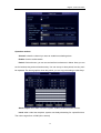
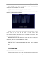
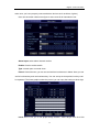
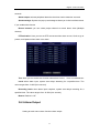
Digital Video Recorder 16. Network connection is not stable. There are following possibilities: u u Network is not stable. IP address conflict. u MAC address conflict. u PC or DVR network card is not good. 17. Alarm signal cannot been disarmed. There are following possibilities: u Alarm setup is not correct. u Alarm output has been open manually. u u Input device error or connection is not correct. Some program versions may have this problem. Please upgrade your system. 18. Alarm function is null. There are following possibilities: u Alarm setup is not correct. u Alarm cable connection is not correct. u Alarm input signal is not correct. u There are two loops connect to one alarm device. 19. Record storage period is not enough. There are following possibilities: u Camera quality is too low. Lens is dirty. Camera is installed against the light. Camera aperture setup is not correct. u HDD capacity is not enough. u HDD is damaged. 20. Cannot playback the downloaded file. There are following possibilities: u There is no media player. u No DXB8.1 or higher graphic acceleration software. u There is no DivX503Bundle.exe control when you play the file transformed to AVI via media player. u No DivX503Bundle.exe or ffdshow-2004 1012 .exe in Windows XP OS. 21. Forget local menu operation password or network password Please contact your local service engineer or our sales person for help. We can guide you to solve this problem. 64 Digital Video Recorder Addenda B DVR installation Check unpacked DVR u When you receive the DVR from the shipping agency, please check whether there is any visible damage to the DVR appearance. u Open the box to check the accessories. Please check the items in accordance with the list on the warranty card u Remove the protective film of the DVR Front Panel and rear Panel u This series DVR has two different front panels. You can refer to instruction u The product model in front panel is the important information, please check with your orders u The sticker on the rear panel is very important for our sales service, please keep it in a good situation, do not tear up, and diskard. It is needed to provide the product series number when you call for sales service Check after open the case converter Please check whether there is any visible damage on the cover, and the data cable in front panel, power cable, fan power connections. Please carefully read those warning and any query please contact us. 1. Before installation, please open the package and check all the components listed. Note: See attachment file B 2. All installation and operation here should conform to local electrical safety codes 3. The DVR should be installed in a cool, dry place away from direct sunlight, inflammable, explosive substances and etc. Heavy stress, violent vibration or water splash are not allowed during transportation, storage and installation. HDD installation DVR need install HDD first, 1 ~ 2 HDDs could be installed into DVR enclosure (no 65 Digital Video Recorder capacity limit), we recommend high-speed HDD 7200rpm or higher, and the SATA cable included in package 1.Loosen the screws on the top cover 2.open the cover 3. Put the HDD on the HDD bracket 66 Digital Video Recorder 4. Use provided HDD screws, install HDD on the bracket 5. Fix the HDD bracket on the DVR HDD bracket 6. Use SATA cable connect to the DVR main board SATA ports, 67 Digital Video Recorder 8. And then connect power cord to the HDD 9. Close the DVR enclosure and screw firmly Rack Mounting We DVR uses standard 2U enclosure and adapt for industry rack mount 68 Digital Video Recorder Steps and notes: 1 Fix the enclosure by 6 screws 2 Temperature should be lower than 35℃ (95°f). 3 15 cm (6 Inch) free space around the unit, be sure air flow is not obstructed. 4 Install the unit from top to bottom 5 Please check input voltage and device power button match or not. This version of User’s Manual for Standard 1U / 2U and Compact enclosure, Video Input and Output Video input connections: u DVR provide BNC video input connector, input signal format PAL / NTSC (1.0VP-P,75Ω) u We suggest use coaxial cable for better video quality, video gain amplifier device or optic fiber may needed if long distance transmission u Please make sure all coaxial cables are connected filmy. u Note: The camera should be installed in a proper location, avoid direct sunshine backlighting, or low lighting. We recommend using the camera with backlighting compensation and low light compensation function 69 Digital Video Recorder Make sure both camera and DVR are grounding properly The coaxial cable should away from any devices or circuit with electromagnetic interference Video output connection u DVR have BNC (PAL BNC 1.0VP-P, 75Ω) video output and VGA video output, can display at the same time u When you connect the DVR with a TV monitor or VGA monitor, the DVR can automatically detects the monitor type u We recommend surveillance the monitor specially designed for best display quality When you use TV monitor or PC monitor, please note: u Make sure the monitor grounding properly u Degaussing frequently for better display quality u Away from any devices or circuit with electromagnetic interference u Not suitable for continuously working Audio input and output The DVR audio output signal is more than 200mv 1K (BNC or RCA),can directly connect to low impedance headphones, active speakers, or other devices via amplifier Note: if the active speakers and microphones are too close, there will cause high-frequency noise output, to avoid: u Adjust the speakers volume to lower level u Adjust the speakers and microphones location u Use more sound-absorbing material in application environment, to reduce the audio 70 Digital Video Recorder reflection u Use better directional microphones Alarm input and output Alarm output sockets u C1 NO1 ; C2 NO2 are 2 groups normal open linkage output(switching value), "↓ ":grounding u 2 channels switching alarm output(normal open contact), alarm device should be with individual power supply u Alarm when loop alarm grounding u To avoid overload, please refer to relay specification as below: Relay specification: JRC-27F Model: Material of the touch Silver Rated switch capacity 30VDC 2A, 125VAC 1A Rating (resistance Maximum switch power 125VA 160W load) Maximum switch voltage 250VAC, 220VDC Maximum switch currency 1A Between contacts with same polarity 1000VAC 1minute 50/60Hz Between contacts with different polarity 1000VAC 1minute 50/60Hz Between contact and winding 1000VAC 1minute 50/60Hz Between contacts with same polarity 1500V (10×160us) Insulation Surge voltage Length of open time Max 3ms. 71 Digital Video Recorder Length of close time Longevity Max 3ms. Mechanical 50×106 times (3Hz) Electrical 200×103 times (0.5Hz) -40℃ ~+70℃ Temperature Alarm output note: Max alarm output no more than 1A u Avoid the power overload when output loop, may cause the damage u Use the co contactor to isolate when high-power load Alarm input sockets: u Show on the figure, the second row 1, 2, 3, 4, 5, 6, 7, 8, corresponded to alarm input ALARM1~ALARM8 u Alarm input type could be normal open or normal close u Grounding joining-up in parallel with Alarm detector and DVR u Alarm detector NC port connected to DVR alarm input(ALARM) u The alarm device should be grounding with DVR when use the outer power supply Alarm input note: u Grounding alarm input u Alarm input require the grounding voltage signal u Use the co contactor to isolate when the alarm device connected to 2 sets of DVR, or 1 set of DVR and other device 72 Digital Video Recorder PTZ control connection Show as on figure, “RS-485, A, B” refer to RS485 A, B wire, connect to encoder or other control device PTZ & DVR connection 1、Connect the speed dome camera RS485 cable to DVR RS 485 port 2、Connect the speed dome camera video cable to DRV video input 3、Connect power supply PTZ connection note: u Make sure both grounding for PTZ decoder and DVR, or else common mode voltage will cause the malfunction of PTZ control, we recommend to use the shielded twisted-pair cable u Avoid the high voltage power interference, ensure the good cable wiring and avoid the lightning stroke u 120-ohms resistance should be needed to ensure the signal quality, if more PTZ decoder connected u The DVR RS485 cable should not be parallel connected with other RS485 devices u The voltage between decoder wire A,B port should be less than 5V u Make sure the grounding for front device 73 Digital Video Recorder Addenda C overview of Navigation and Controls System Boot up Connect the power supply, press switcher on backside panel, indicator light up and DVR boot up. Default display mode is multiple picture output System will start record video if set at schedule record mode, and the record channel indicator light up. Login When the system boots up, Click Enter or left click mouse, you can see the login interface. There are 2 default users: “admin” “guest”. “admin” users have administrator right. The default password is “123456” for all 2 default users’ account. “guest” user only can review playback and backup. Password protection: you can input password 5 times within 30 minutes, otherwise the account will be locked. For your system security, please modify you password after first login. You can use USB mouse, front panel, remote controller or keyboard to input. About input method: Click to switch between numeral, English character (small/capitalized) and Chinese 74 Digital Video Recorder System Shutdown Note: Power off system before change the HDD. Method 1: Press the POWER button at the front over 3sec to stop the disc video recorder, then shut the power off at the rear panel. Method 2: System menu -> Shut down the system Method 3: System menu -> Main menu ->Management tools -> Shut down the system. Preview Enter into “Preview” menu, you can setup date and time according to “General Setting”, or setup the channel name according to “Output Mode” The logo displayed on The logo displayed on the screen 1 the screen when 2 when motion detection recording The logo displayed on The logo displayed on the screen 3 the screen when video 4 when camera masking occur lost occur Auto Resume after Power Failure The system can automatically backup video and resume previous working status after power failure. Replace Button Battery Please make sure to use the same battery model if possible. We recommend replace battery regularly (such as one-year) to guarantee system time accuracy 75 Digital Video Recorder Addenda D: WEB CLIENT OPERATION IE Browser Setup Please make sure your PC installed Microsoft Internet Explorer 6.0, and DirectX 9.0 or higher version., Note: Please turn off the Firewall and Antivirus Software if necessary. When log in the DVR first time, if all the functions run properly, in this case you could set the Security as default level. Login This chapter mainly introduces DVR’s Web client-end operation. Open IE and input DVR address in the address column. For example, if your DVR IP is 192.168.1.108, then please input http:// 192.168.1.108 in IE address column... System pops up warning information to ask you whether install webrec.cab control or not. Please click yes button Please input your user name and password. Default factory name is admin and password is 123456 Note: For security reasons, please modify your password after you first login Please check the following items: 6.1 Network connection is right 6.2 DVR and PC network setup is right. IP address, Subnet Mask, Gateway, Please refer to network setup(main menu->setting->network) 3, Use order ping ***.***.***.***(* DVR IP address) to check connection is OK or not. TTL value 64 4. Web OCX will be downloading and install automatically, when update a new OCX, old version OCX should be uninstalled System can automatically download latest web control and the new version can overwrite the previous one. 76 Digital Video Recorder WEB client review interface After you logged in, you can see the main window, double click the channel number in the right side tree structure, when the icon becomes a small camera, you can review this channel. Toolbar There are few function buttons in the toolbar, at upside and downside Playback:Record video inquiry, playback and download Configuration:DVR parameter configuration。 About: DVR Web Server version; Quit: Quit the Web Server。 Preview window switch :Set Fluency :Full screen display; :Single channel display 77 Digital Video Recorder :4-channel display; :6-channel display; :8-channel display; :9-channel display; : 13-channel display; :16-channel display; :20-channel display; :25-channel display; :36-channel display。 Review the channel Double click the channel number in the right side tree structure, when the icon become a small camera, you can review this channel. 78 Digital Video Recorder Review Review toolbar in the up-right side of channel, shown as below ; : Capture picture. You can snapshoot important video. All images are memorized in folder C:\RC\; : Local record. When you click local record button, the system begins recording and this button becomes highlighted, all videos are memorized in folder C:\RC\ ; : voice talk : Close video。 PTZ control function WEB client’s PTZ function: 79 Digital Video Recorder u u u u u u u u u u u Direction Key: 8 direction keys, Click and holding for continuous control. Step Speed: Control PTZ speed and patrol speed. Zoom: adjust and control PTZ zoom Focus: adjust and control PTZ focus Iris: adjust and control PTZ iris. Presets: Call preset after set preset value Pattern: you can input pattern value and then click start record button to begin PTZ movement. Flip: control PTZ camera to start vertical flip Auto Scan: control PTZ camera to start auto scan Auto tour: input auto tour value and preset value. Click add button, you have added one preset in the tour PTZ: Auto scan, Tour, Pattern, Present settings 80 Digital Video Recorder Click PTZ setup button you can see the following interface u Click the PTZ camera channel, move the camera to you desired location and then click left limit button. Then move the camera again and then click right limit button to set a right limit. Now you have set one auto scan u Click the PTZ camera channel, move the camera to your desired location and then input preset value. Click add button, you have set one preset. You can click to set one preset, or delete one preset u Click the PTZ camera channel, input auto tour value and preset value. Click add button, you have added one preset in the tour. Repeat the above procedures you can add more presets in one tour. Color setting Set hue, brightness, contrast, saturation and AGC : Brightness; : Contrast; 81 Digital Video Recorder : Hue; : Saturation; : Reset all to default; Other setting snapshot:Snapshot, and path:C:\RC\ record path:Record path:C:\RC\ reboot:Restart the device record size:Set file size 82 Digital Video Recorder WEB CLIENT Configure System Info In the main window, click config button, you can see an interface is shown as u System Information: Click device configuration button, you can see the following interface, Hardware version, HDD information, Interface, Log inquiry. u Setting: Setting includes the following items: General, Encode setup, Schedule, RS232, Network, MUL-DDNS, FTP, Alarm setup, Detect, Pan/Tilt/Zoom, Tool Advanced: set DVR’s record, auto maintenance 83 System Setting General General interface is shown as below.; u u u u u u u u System time: Here is for you to modify system time. Please click Save after your modification Data format: Here you can select data format from the dropdown list. Data separator: Please select separator such as – or /. Time format: there are two options: 24-H and 12-H. HDD full: there are two options: stop recording or overwrite the previous files when HDD is full. Pack duration: Here you can select file size. Default setup is 60 minutes. Device No.: when you are using one remote control to manage multiple DVRs, you can give these DVRs serial numbers respectively. Click address button in your remote control and then input the correct device number, now you can control the DVR now. Video standard: PAL. (for your reference only) 84 Digital Video Recorder Encode Encode setup includes the following items u u u u u u u u u u u u u Channel: Here is for you to select a channel. Compression: H.264; Data stream: Regular and extra data stream; AV enable: Video/Audio. System only displays video by default. You need to manually enable audio function Resolution: CIF / QCIF Differentiating rate: stocking differentiating rate’s type is CIF or QCIF; Bit rate: There are two options: CBR and VBR. You can only set video quality in VBR mode, 10Kb/s-4096Kb/s variable Frame rate: The value ranges from 1f/s to 25f/s (PAL) and 1f/s to 30f/s (NTSC) Bit rate number: set bit rate according to web status, 10kb/s-4096kb/s adjustable; Frame interval: can set 1 frame, 2-12 optional. Image control: brightness, contrast, color, saturation and AGC for selected channel; OSD Overlay: time, date, title overlay. Click “copy” as following chart showing: 85 Digital Video Recorder Schedule Schedule includes the following interface When DVR boots up, it is in 24-hour continuous record. In this interface you can set record type, record time and period. Record type includes regular record(R), motion detection record (M) and alarm record (A). u Channel: select the channel number you desire. u Week: you can select from the dropdown list. Or you can select at the bottom of the interface. u Prerecord: system can record the three to five seconds video before activating the record operation into the file.(Depends on data size) u Period: There are six periods for you to set. Please click set button of the corresponding period. Please note all the setup here shall be in one day. E.g. 00.00 to 24.00. Tip After you finished setup for one channel, you can click “save as” button, system pops up the following interface. Now you can copy one channel setup to other channels.; 86 RS2332 RS232 includes the following items. u Function: There are various devices for you to select. Console is for serial port or min-end platform to upgrade program. Keyboard is for you to use special keyboard to control current device. u Baud rate: Please select as you desire. u Data bit: The value ranges from 5 to 8. u Stop bit: There are three options: 1/1.5/2. u Parity: There are three options: none/odd /even. 87 Network Network interface is shown as below. This interface includes the following items; u u DNS: Set DNS and backup DNS address DDNS: Set DDNS type, Domain name, User name, Password; 88 Digital Video Recorder User Manual u UPNP: Set UPNP, Web Port, TCP Port u PPPoE: Set PPPoE User name, password, and IP address u PTZ: Set PTZ channel, protocols, bitrate, stop bit, data bit, varity, Default: PELCOD,1,9600,8,1, 89 Digital Video Recorder User Manual Reset to default: Reset selected functions to default 90 Digital Video Recorder User Manual Alarm Alarm in: Select corresponding alarm in channel Video Detect: Set video detection area, latch, output channel, PTZ, Buzzer. Alarm output: select alarm activation channel when alarm occurs. 91 Digital Video Recorder User Manual Exception Deal: Event type: no disk space, hard disk error, Not enough space, network failure ,IP address conflict, Buzzer, send e-mail Advanced set DVR’s record, Read, Write, auto maintenance。 Disk Manage: Set HDD as Read, Write, Read-only, Reduncey, Erase the data, 92 Digital Video Recorder User Manual Restore Upgrade: Select update file to upgrade the DVR; 93 Digital Video Recorder User Manual Record Control : Set record status: Schedule / Manual / Stop User Account User Account: Management user account, adding users, modity users, password, group. Auto Maintenance, Reboot, auto delete old file 94