1
US 6,401,154 B1
6
5
A UART block 40 includes tWo PC16550-compatible
Accordingly, the ISA bus 122 is a standard component of all
PC/AT-compatible systems. The ISA bus 122 has several
features, many of Which are discussed beloW. A general
function of the ISA bus 122 is to provide a mechanism for
8- or 16-bit devices to be added to the computer system S
such that the devices may interact With its other circuitry.
For example, an external device may need to interrupt the
processor 100. Accordingly, the device needs to interact With
the interrupt subsystem 112. Adherence to ISA bus 122
UARTs, both capable of running 16450 and 16550 software.
The UART block 40 supports DMA operation, a FIFO mode,
an internal baud rate clock to handle baud rates up to 1.5M
bits/s, false start bit detection, break detection, full-duplex
operation, and other features.
A Watchdog timer block (WDT) 32 is a mechanism to
alloW system softWare to regain control of the microcon
troller M When the softWare fails to behave as expected. The
Watchdog timer block 32 supports up to a 30-second time
10
requirements makes such interaction possible. FIG. 2 shoWs
a 16-bit device 126 and an 8-bit device 128 connected to the
ISA bus 122. These devices may be either soldered on the
system board or they may be connected via an ISA expan
sion slot connector. An example of an 8-bit device is a ?oppy
peripherals include the DMA controller 22, the PIT 62, the
15 disk drive controller While a ?xed disk drive controller is a
PIC 48, the UARTs 40, and the RTC 60.
out With a 33 MHZ CPU clock.
The PC/AT compatibility logic 74 provides PC/AT
compatible functions. The PC/AT compatible integrated
commonly used 16-bit device. Both are typically found in
This particular microcontroller is illustrative. The tech
niques and circuitry according to the invention could be
PC/AT systems.
The folloWing sections describe particular requirements
and implementations for PC/AT compatibility of the micro
controller M. For simplicity and clarity, requirements Which
applied to a Wide variety of microcontrollers and other
similar environments. The term “microcontroller” itself has
differing de?nitions in industry. Some companies refer to a
processor core With additional features (such as I/O) as a
are common across most computer system architectures are
“microprocessor” if it has no onboard memory, and digital
signal processors (DSPs) are noW used for both special and
general purpose controller functions. As here used, the term
“microcontroller” covers all of the products, and generally
means an execution unit With added functionality all imple
mented on a single monolithic integrated circuit.
not described herein. Thus, for example, no mention is made
of chip select signals, except Where pertinent to discussing
particular architectural requirements of a PC/AT-compatible
system.
Programmable Interrupt Controller (PIC)
PC/AT Compatibility Requirements
Before discussing the PC/AT-compatible features of the
microcontroller M of FIG. 1, a brief introduction to PC/AT
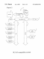
compatibility is provided. FIG. 2 is a block diagram of a
computer system S used to illustrate some of the basic
hardWare features of a PC/AT-compatible computer. First, a
processor 100, also knoWn as a microprocessor, is shoWn.
PC/AT-compatible systems are based upon the Intel 8088 or
In the PC/AT World, all hardWare interrupts to a processor
are channeled through tWo interrupt controllers. The inter
rupt controllers are Intel 8259A or their equivalent devices.
The PC/AT architecture supports tWo cascaded 8259A PICs
for a total of ?fteen maskable interrupt request sources. The
interrupt controllers are eight-input devices that can accept
compatible microprocessors. The 8086, 80286, 80386,
interrupt signals from several devices, assign priorities to
each interrupt, and then interrupt the processor. Upon receipt
80486, and Pentium microprocessors are all considered
PC/AT-compatible With the 8088 microprocessor.
of the interrupt, the processor automatically reads the par
FIG. 2 also shoWs a processor bus 102. The processor bus
102 connects the processor 100 to the other components of
ticular interrupt controller to determine the source of the
highest priority interrupt. Once determined, the processor
calls the appropriate softWare interrupt routine.
the computer system S and provides a pathWay for address,
data, and control signals to traverse. Also shoWn coupled to
the processor bus 102 is a memory or DRAM 104. The
TWo interrupt controllers, a master and a slave, are used
so that ?fteen levels of interrupts are available. The INTR
DRAM 104 contains data such as, for example, instructions
output of the slave is connected to the IR2 input of the
that the processor 100 executes.
45 master. This con?guration enables the slave interrupt con
troller to interrupt the master interrupt controller to cause an
Next, a bus controller 106 coupled to the processor bus
interrupt. Although not required, typical PC/AT systems
implement additional logic to alloW programmable steering
of the IRQs. The programmable interrupt controllers provide
102 is shoWn. The bus controller 106 contains logic Which
enables the processor 100 to communicate With external
devices. A ROM device 108 is shoWn coupled to the bus
controller 106. The ROM 108 contains ?rmWare instructions
Which are executed by the processor 100 When the computer
other features Which are Well-knoWn to PC/AT system
designers.
system S is poWered up.
A clock 124 is also shoWn as input to both the processor
100 and the bus controller 106. The clock 124 enables
synchroniZation of these and other devices so that the
processor 100 can communicate With other devices in the
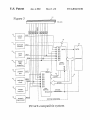
FIG. 3 is a block diagram illustrating the interrupt sub
system 112 for the PC/AT-compatible system introduced in
FIG. 2. The interrupt subsystem 112 consists of tWo interrupt
55
computer system S.
of resources in the system S. The eight interrupts coming in
from the slave PIC 132 produce a single INTR signal Which
FIG. 2 shoWs tWo peripheral buses, an X bus 120 and an
ISA bus 122. The X bus 120 is simply a buffered version of
in this case goes to the IR2 line of the master PIC 130, as
the ISA bus 122. As shoWn in FIG. 2, several components of
PC/AT-compatible systems are connected to the system
through the X bus 120. These components include a DMA
subsystem 110, an interrupt subsystem 112, a keyboard
subsystem 114, a real-time clock and CMOS RAM sub
system 116, and system timers 118.
Also shoWn as part of the computer system S is an ISAbus
122. ISA is an acronym for Industry Standard Architecture.
controllers: a master PIC 130 and a slave PIC 132. Together,
the tWo PICs 130 and 132 receive interrupts from a variety
65
FIG. 3 shoWs. In a PC/AT-compatible system, the interrupt
priorities are assigned in ascending order. That is, IRO has a
higher priority than IR1 and IR2, and so on. Because the
eight interrupts from the slave PIC 132 interrupt the IR2 line
of the master PIC 130, all eight of the slave interrupts have
higher priority than IR3 through IR7 of the master PIC 130.
As FIG. 3 shoWs, the interrupt inputs are labeled IRQO
through IRQ15, for a total of sixteen interrupts for the tWo