1
US 6,401,154 B1
9
10
control the global interrupt mode for each of the PICs. Each
bit, along With the respective LTIM bit of PICICW1 register
the NMI sWitch matrix 300. NMI sharing is possible With
this architecture but is preferred for level sensitive NMI
for the same PIC (see FIG. 5B), provides a global or
individual channel interrupt mode for the respective PIC is
requests.
The polarity control signal per external interrupt source is
set. If this bit is set and the LTIM bit cleared, all the PIC
common to those used across the channel sWitch matrices.
The NMI enable bits for each source are enabled/disabled
interrupt channels Will recogniZe edge sensitive interrupt
requests. If this bit is cleared, hoWever, the PIC channels can
be programmed individually to select either edge or level
under softWare control.
PC/AT Compatibility
sensitive interrupt recognition. Bit 2 of this register controls
slave 2 PIC global interrupt mode enable. Bit location [1]
controls PIC global interrupt mode enable for slave 1 and bit
location [0] controls the PIC global interrupt mode enable
The PIC 48 of the microcontroller M is designed to
support PC/AT compatibility. In this respect, the program
mable interrupt router 168 may be con?gured at startup or
during normal operation to appropriately route ISA interrupt
signals to the corresponding interrupt channels of the slave
for the master PIC. According to one embodiment, for
PC/AT compatibility, bits [1:0] should set together With bits
S2(set) and S5(cleared) of register PIC ICW3 (see FIG. 5C).
In such a case, slave 2 controllers bypass any interrupt
15
sources mapped to slave 2 controller and should have no
PICs 162 and 164 and the master PIC 160. Table 1 beloW
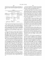
shoWs the interrupt channel assignment for PC/AT
compatible systems and the corresponding interrupt of the
effect.
microcontroller M. These channel assignments are imple
Externally generated interrupts e.g. INTA—INTD and
GPIRQO—GPIRQ10 go through the polarity inversion logic
mented in softWare, typically during BIOS initialiZation.
250 to further provide ?exibility in the architecture to
accommodate different types of interrupt sources. For
example, a PCI generated interrupt request that is active loW
must be inverted using this programmable inversion logic
250 prior to reaching the interrupt priority channel to Which
TABLE 1
PC/AT interrupt channel assignment for the microcontroller M
25 No.
it is mapped before the controller can recogniZe a valid
interrupt request. All internally-generated interrupt signals
may have the correct active high polarity and therefore do
not require inversion. Although this embodiment is
described in connection With the cascaded interrupt control
ler architecture, it should be understood this same concept
may be extended With only minor modi?cation to any
interrupt controllers that recogniZe either ?xed active (high
or loW) interrupt requests or ?xed edge-triggered (loW-to
high or high-to-loW) interrupt requests.
I/O device
microcontroller M interrupt source
IRQO
System Timer( )
Internal via pitiOiirq
IRQ1
Keyboard Interface
External via General Purpose IRQ
pin
IRQZ
IRQ3
IRQ4
IRQ5
Slave1 cascading
Serial Port 2
Serial Port 1
Parallel Port 2
IRQ6
Floppy Disk Controller
Cascaded from Slave Controller
Internal via uartZiirq
Internal via uartliirq
External via General Purpose IRQ
pin
External via General Purpose IRQ
pin
IRQ7
Parallel Port 2
External via General Purpose IRQ
pin
35
It should also be understood that the architecture is easily
scalable to accommodate more than the number of interrupt
IRQ8
IRQ9
Real Time Clock
Internal via rtciirq
Any 8 or 16 bit ISA device External via General Purpose IRQ
sources shoWn simply by Widening the channel sWitch
IRQ1O
Any 8 or 16 bit ISA device External via General Purpose IRQ
routed through a simple OR device, additional interrupt
IRQ11
Any 8 or 16 bit ISA device External via General Purpose IRQ
sources can be added Without signi?cant changes in the
hardWare design. A modi?cation to the AND gate array 252
IRQ12
Mouse Interface
(FIG. 6) and, if an active loW interrupt is used, a modi?ca
tion to the polarity inversion array 250 could easily be made
IRQ13
Numeric Co-processor
IRQ14
Any 8- or 16-bit ISA device External via General Purpose IRQ
to accommodate additional sources. Also, softWare control 45
IRQ15
can easily be modi?ed to gate the additional sources.
Any 8- or 16-bit ISA device External via General Purpose IRQ
pin
matrix 168. Speci?cally, since the interrupt sources are
pin
pin
External via General Purpose IRQ
pin
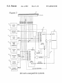
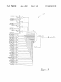
In FIG. 6, all of the thirty-tWo hardWare interrupt sources
Internal via ferriirq
pin
pin
are common to all the tWenty-tWo channel routers 201—222.
Returning to FIG. 4, a multiplexor 170 and 172 is imple
The individual bits of polarity [14:0] per external interrupt
source is also common to all the channel routers 201—222.
mented at the output of each slave controller 162 and 164 to
The decoder for the enable signals is not shoWn; only the
decoded representation of the signals is shoWn. Those
provide PC/AT compatibility. When signals s2 and s5,
skilled in the art are generally familiar With the design of
decoders When given an encoder design. Each channel
crossbar sWitch matrix 201—222 has its oWn unique inter
cleared respectively under softWare control, PC/AT compat
ibility could be maintained Whereby the outputs of slave 1
control signals for the multiplexors 170 and 172, are set and
nally generated hardWare interrupt trigger irq[1]itrig—irq
controller is cascaded onto IR2 input of master controller
respectively and slave 2 controller is disabled. Different
[22]itrig.
master and slave(s) con?gurations could be programmed
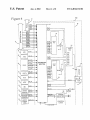
Turning to FIG. 7, there is also a non-maskable interrupt
(NMI) sWitch matrix 300 for all the interrupt sources. Signal
depending on the signals s2 and s5.
Additional embodiments exist to provide further ?exibil
ity. One alternate embodiment is to provide another level of
sWitch matrix betWeen the slave controllers 170 and 172 and
the master controller 160. This alloWs routing the output of
each slave to any input of the master controller under
softWare control. This additional sWitch matrix Would be
55
nmiitrig is an internally generated NMI trigger bit Which
can be used to generate an NMI under softWare control. FIG.
7 shoWs the logical OR function of this sWitch matrix,
similar to the channel routers 201—222. Signal nmi is pre
conditioned to be synchronous to the processor clock before
being presented to the processor 36 and the circuit is not
shoWn. Similarly, this architecture can be scaled to accom
modate more NMI sources than What is shoWn by Widening
65
implemented in much the same Way as the interrupt router
168. Speci?cally, through minimal additional softWare
control, additional interrupt trigger bits associated With the