1
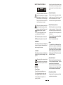
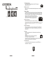
Speco Technologies
200 New Highway • Amityville, NY 11701
For more information on our products go to:
www.specotech.com or contact us at: 1-800-645-5516
www.specotech.com
5x4 Multi-Source/Multi-Zone Matrix Distribution P.A. Amplifier
User's M anual
PL200M
IMPORTANT!
Please read this manual carefully before operating
this unit for the first time.
All rights reserved to Speco Technologies. All features and content might be
changed without prior notice. Any photocopy, translation, or reproduction of
part of this manual without written permission is forbidden.
SAFETY RELATED SYMBOLS
Unplug the product before electrical storms
occur and when unused for long periods of
time to reduce the risk of electric shock or
fire.
CAUTION
RISK OF ELECTRIC SHOCK
DO NOT OPEN
This symbol, wherever used, alerts
you to the presence of un-insulated
and dangerous voltages within the
product enclosure. These are voltages
that may be sufficient to constitute the
risk of electric shock or death.
This symbol, wherever used, alerts
you to important operating and maintenance instructions. Please read.
Protective Ground Terminal
AC mains (Alternating Current)
Hazardous Live Terminal
ON: Denotes the product is turned on.
OFF: Denotes the product is turned off.
WARNING
Describes precautions that should be
observed to prevent the possibility of
death or injury to the user.
CAUTION
Describes precautions that should be
observed to prevent damage to the
product.
External Connection
Always use proper ready-made insulated
cabling (power cord). Failure to do so could
result in shock/death or fire. If in doubt,
seek advice from a registered electrician.
Do not Remove any Covers
Within the product are areas where high
voltages may present. To reduce the risk
of electric shock do not remove any
covers unless the AC mains power cord
is removed.
Covers should be removed by qualified
service personnel only.
No user serviceable parts inside.
Fuse
To prevent fire and damage to the
product, use only the recommended
fuse type as indicated in this manual.
Do not short-circuit the fuse holder.
Before replacing the fuse, make sure
that the product is OFF and disconnected
from the AC outlet.
Protective Ground
Disposing of this product should
not be placed in municipal waste
and should be separate collection.
WARNING
Power Supply
Ensure that the main voltage source
(AC outlet) matches the voltage rating
of the product. Failure to do so could
result in damage to the product and
possibly the user.
Before turning the product ON, make sure
that it is connected to Ground. This is to
prevent the risk of electric shock.
Never cut internal or external Ground wires.
Likewise, never remove Ground wiring
from the Protective Ground Terminal.
Operating Conditions
Always install in accordance with the
manufacturer's instructions.
1
To avoid the risk of electric shock and
damage, do not subject this product to
any liquid/rain or moisture. Do not use this
product when in close proximity to water.
Servicing
Refer all servicing to qualified service
personnel only.
Do not perform any servicing other than
those instructions contained within the
User's Manual.
Do not install this product near any direct
heat source. Do not block areas of
ventilation as doing so could result in fire.
Keep product away from open flames.
IMPORTANT SAFETY INSTRUCTIONS
Read these instructions
Follow all instructions
Keep these instructions. Do not discard.
Heed all warnings.
Only use attachments/accessories
specified by the manufacturer.
Power Cord and Plug
Do not tamper with the power cord or plug.
These are designed for your safety.
Do not remove Ground connections!
If the plug does not fit your AC outlet seek
advice from a qualified electrician.
Protect the power cord and plug from any
physical stress to avoid risk of electric shock.
Do not place heavy objects on the power
cord. This could cause electric shock or fire.
Cleaning
When required, either blow off dust from
the product or use a dry cloth.
Do not use any solvents such as Benzol
or Alcohol.
For safety, keep product clean and free
from dust.
2
G
-
+
COM
4
8
25V
19. AC Voltage Selector
In the US, set the AC Voltage Selector to the left (115V) for power
between 100V and 127V.
70V
19
20.Monitor Line Out
Monitor Line Out can be connected with another appliance such as an amplifier,
recorder, etc.
0
0
70V
70V
Connecting the speakers with 70V output
0
70V
21.Monitor 1W8
The terminal is meant for the connection of a small external loudspeaker that gets
driven by an internal auxiliary power amplifier, providing a nominal output of 1Watt.
This could also be used for a “Music on Hold output.” Only the mixed audio signal
coming from "AUX IN" is included in the outputted signal.
20 21 22 23
In addition, the output signal is controlled only by the volume
control of the "CH4" & "CH5" music signal level controls.
22."Priority" Terminal.
When these terminals are short-circuited (i.e. By means
of using an electrical switch), the audio signals coming from "CH4", "CH5", are
attenuated while the signals coming from"CH1", "CH2","CH3" are gaining
priority.
23.Input "AUX Paging"
This terminals input lets you connect to an auxiliary signal . The input features a
"Voice Priority" function, which overrides all other input signals once an auxiliary
message is sent.
24. a. Zone
There are four dip switches here. Push the dip switch up to switch the zone
off and vice versa.
24
b.Volume
This controls the volume of a sound source connected to
the "Tel Paging". Turning the knob clockwise
increases the volume of the corresponding source. It is recommend to leave
the control of unused inputs at their minimal setting "0".
25.''LINE IN" inputs
An audio source with a high level output signal , such as an AM/FM tuner , a
cassette deck, a CD player, etc.
25
8
5
SPECIFICATION
Model:
The Front panel
PL200M
Output power c apacity:
RMS:40W 4; Peak output: 90W 4
Frequency response:
50-17000 Hz (-3dB)
Totalh armonic distortion:
Less than 0.5%(1KHz-nominal power capacity)
Signal/noise r atio:
Inputs / sensitivity-impedance:
CH 1
CH 2
CH 3
CH 4
CH 5
PL200M MULTI-ZONE DISTRIBUTION P.A. AMPLIFIER
GAIN
GAIN
GAIN
GAIN
GAIN
TREBLE
TREBLE
TREBLE
TREBLE
TREBLE
ZONE 1
ZONE 2
VOLUME
VOLUME
PL
ON
Microphone: Bet ter than 55 dB rated output
BASS
Line:b etter than 6 0dB rated o utput
BASS
BASS
BASS
BASS
MON
MUTE
CH1-3/X LRa nd 6.3mm combination socket: bal/unbal
MUTE
VOL
MUTE
VOL
MUTE
MUTE
VOL
VOL
Phone
Volume
Z1
LINE I N/ stereo RCA jack/ unbalanced
Z3
Zone
Selector
Z2
Z1
Z4
Z3
Zone
Selector
Z2
Z1
Z4
Z3
Zone
Selector
Z2
Z1
Z4
Z3
Zone
Selector
ZONE 4
VOLUME
VOLUME
POWER
VOL
Mic: - 42dB /-38dB-600ohm,bal/un bal.
Line: -26B/-20dB-15Kohm, bal/unbal.
OFF
MON
ZONE 3
Z2
Z1
Z4
Z3
Monitor
Volume
Z2
Z4
Phone
MON
MON
Zone
Selector
CH4: -10dB 5 0Kohm
CH5: 0dB 50Kohm
Tone c
Ba ss 10dB-100Hz
Treble 10dB-10KHz
Outputs for s peakers / Ohms:
4 oh m, 8 ohm
Outputs for s peakers / Volts:
25V-70V
Monitor output:
1Wrms
Phone output:
0.5W into 47ohm
Line out:
1.2V
Controls:
5 Gain controls for Ch1-5,
7 Volume contr ols forCh1 -5, tel.pagina, monitor, phone
4 Mas ter volume control
5 Treble controls
5 Bass controls
5 Mute controls
4 Zone select switch for each channel
Indicator:
1. Gain knob
This knob controls input gain. Turn the knob clockwise and the input
increases. Turn the knob counter-clockwise and the input decreases.
CH 1
2. High knob
This is the treble control. You can use it to get rid of high frequency
noises or to boost the sound of cymbals or the high harmonics of
the human voice. The gain range goes from -10dB to 10dB with the
central frequency 10kHz.
1
GAIN
2
TREBLE
3
BASS
4
6
MUTE
7
Z1
Z2
Z4
Z3
Zone
Selector
3.Low knob
This is the Bass control. Boost male voice or kickdrum and bass guitar. Your
system will sound much bigger than what it is. The gain range goes from -10dB
to +10dB and the center frequency is 100 Hz.
4. Mute
Mutes the signals from the corresponding channel.
4 Zone moni tor select switch.
1 AC select switch
5. Mute LED
When the mute key is pressed down, mute LED lights up, and vice versa.
Power indicator
6. VOL knob
This knob controls volume. Turn the knob clockwise, and the volume increases.
Turn the knob counter clockwise, and the volume decreases.
4 Zone output-level meter
1 Moni tor output-level meter
5 Mute indicators
Power s upply/ Consumption:
115/230 V ac( 5%) -60/50Hz /400VA
Dimensions:
483mm(W ) x 132mm( H ) x 310mm(D)
Note: Specification, design and appearance are subject to change without prior notice!
7. Zone selector
Z1, Z2,Z3,Z4 can be considered as signal assignment switches. Press the button
Z1 down and signal will be assigned to ZONE 1. Release the button and it stops
Assigning signal to ZONE1. Z2, Z3,Z4 can be operated in the same way.
8. Phone Volume
This knob controls the volume of the signal from the Phone system
(refer to 7). Turn the knob clockwise to increase the volume, and vice versa.
9. Phone
The amplifier signals can be sent to a pair of headphones
through this socket.
10. Monitor Volume
This knob controls the output signal level to monitor output.
10
5
VOL
3
Phone
Volume
Monitor
Volume
Phone
8
9
10
11. Zone1 VOLUME
VOLUME controls the output signal level of ZONE1.
12.LED VU-meter
This stereo 6 segment LED-meter indicates the level of the
overall output signal.
12
13.MONITOR selector
Pushing the MONITOR button down will connect the signal from amplifier
zone 1 to the monitor output. Releasing the button will then cut off the
signal connection to the monitor. The other three buttons are operated in
the same way.
ZONE 1
INSTALLATION NOTES
VOLUME
MON
1 3 11
The amplifier must be operated under appropriate conditions at all times.
This means that the installation location must provide sufficient ventilation and the
device is not exposed to direct sunlight or the direct radiation or reflection from any
heat source. When installing the loudspeaker systems, choose a location that will
not be affected by extreme and/or constant vibration or other mechanical oscillation.
Also make sure that the speakers are installed at locations that are free from dust
and /or moisture.
CAUTION
14. PL
This LED is the power indicator. When the amplifier is powered on, this LED
lights up. When the amplifier is powered off, this LED lights off.
14
15. Power switch
When the switch is set in the position ON, the unit is powered
15
on. When the switch is set in the position OFF, the unit is
powered off.
PL
ON
OFF
POWER
We strongly recommend that you leave the installation of the PL200M system to
qualified and experienced service technicians who specialize in connecting
electronic equipment. Do not take the risk of Electro-shock. To reduce this risk,
all connections should be made before connecting the amplifier to the main power
supply. Be sure that all connections are correct and that no short-circuit exists.
The overall sound reinforcement installation must be in accordance to the laws,
regulations, standards, and guidelines that are relevant and applicable in the
jurisdiction where the equipment is going to be operated.
AC POWER SUPPLY CAUTION
The Rear Panel
Monitor
Line Out
CAUTION
RISK OF ELECTRIC SHOCK
DO NOT OPEN
G
CAUTION : SHOCK HAZARD - DO NOT OPEN
RISK OF FIRE-REPLACE FUSE AS MARKED.
+
Monitor
1W 8
-
Priority
+
Tel. Paging
T
R
Line Out Bal./Unbal.
Zone 1
G
Line
G
-
+
Before using the amplifier for the first time, make sure that the appliance voltage
is correct. Only connect the amplifier to grounded outlets. Connection of the
amplifier to the main power supply (115/230Vac) has to be accomplished by
inserting the supplied cord into the corresponding socket .
Power Amp. Output
Com 4
8
25V
70V
Mic
Phantom
Line Out Bal./Unbal.
TEL
Zone
Main Power
115/230V~50/60Hz
Zone 2
Volume
AC Fuse:
110-120V: T6.3AL 250V
220-240V: T3.15AL 250V
Attention:
Afin de reduire le risque d'incendie remplacer seul par un
fusible de meme type!
-
+
Line Out Bal./Unbal.
Caution:
Replace fuse only with same and rated type!
Caution:
To reduce the risk of fire or electric shock. Do not expose
this appliance to rain or moisture. Do not remove cover.
There are no user serviceable parts inside. Refer servicing
to qualified service personnel.
G
Power Amp. Output
Com 4
8
25V
70V
Sound column
Ch.1
Phantom
Line
Ch.5
Line
Mic
Phantom
Line
Mic
Zone 3
G
-
+
Power Amp. Output
Com 4
8
25V
70V
Horn speaker
Contact
"VOICE PRIORITY"
Ch.4
Speaker
Line
Line Out Bal./Unbal.
Zone 4
G
-
+
Power Amp. Output
Com 4
8
25V
70V
Attention:
Pour reduir les risques d' incendie ou de choc electrique
ne pas exposer a la pluie ou l' humidite. Ne pas enlever
le couvercle. Aucun reglage al' interieur. Pour reparation
consulter une personne qualifiee.
Ch.3
Ch.2
Speaker
Aux.signal
Amplifier
16. Intelligent fan
The PL200M is equipped with an intelligent fan. It will only begin
to run if the temperature is above 50 degrees C, and the speed
of the fan will increase as the temperature rises.
17. AC Input
This inlet connects the unit with the main power.
18. AC fuse
The fuse protects the alternating current circuit of the unit,
and the fuse can only be replaced in the event of fuse
damage.
Recorder
16
17
18
CD player
Microphone
Mains
AM/FM tuner
Cassette recorder
4
Desk Top Microphone
9
26.The mono MIC/LINE channels
G
-
+
COM
4
8
25V
70V
The channels are numbered from 1 to 4. You can connect
balanced, low impedance microphones to the XLR socket.
On the 1/4" phone jack you can connect either a microphone or
a line level instrument. You should never connect an unbalanced
microphone to the XLR socket as it could damage both
the Microphone and the Mixer.
26
27. Ch1, CH2, CH3 and inputs sensitivity and XLR phantom switch
By turning the switch onto the "LINE" position the CH1, CH2, & CH3
inputs can be connected to an audio source with a high level signal
output. By turning these switches to the MIC position, CH1, CH2,
& CH3 inputs can be connected to a dynamic microphone with low
impedance. By turning the switch into the "Phantom" position, it
connects the phantom power supply for XLR pin2 and pin3
of CH1, CH2, & CH3, which is necessary to operate condenser
microphones. It is recommended to activate this switch with the
general volume set to zero.
Total impedance: 4 ohms
27
G
-
+
COM
4
8
25V
70V
28.Line Out Bal/Unbal
These terminals can be connected to other appliances, such as amplifiers,
recorders, etc.
Total impedance: 8 ohms
29.Power Amp Output
These terminals allow for the connection of speakers.
28
29
G
-
+
COM
4
8
25V
0
70V
25V
0
25V
Connecting the speakers with 25V output
6
7
0
25V