1
User’s
Manual
SS400G
MLSS Converter
[Style: S2.2]
IM 12E6B1-02E
R
IM 12E6B1-02E
5th Edition
i
<Introduction>
Introduction
The SS400G MLSS converter is used in configuring of the EXAss series SS400 MLSS metering
system. The use of this converter in combination with the SS300G MLSS sensor allows continuous
measurement of MLSS/SS.
This manual covers all of the information for handling the SS400G MLSS converter, including installation, and setting of operation parameters, inspection and maintenance. For a better understanding of
the product, other necessary information is also included.
For the SS300G MLSS sensor used in combination with the SS400G and the holder to install the sensor, refer to their respective instruction manuals.
Instruction Manuals for the EXA ss series SS400 MLSS metering system-related equipment are as
follows.
Manuals for associated equipment used with the EXA ss series SS400 MLSS metering system
Model
Title of Manual
Publication no.
SS300G
Sensor
IM 12E6C1-01E
SS350G
Wiper Cleaning Controller
IM 12E6E1-01E
SS380G
Calibration Kit
IM 12E6D1-01E
PH8HG
Guide Holder
IM 12B7M2-01E
HH350G
Well Bucket Type Holder
IM 19H1B1-01E
FH350G
Flow-Through Type Holder
IM 19H1C2-01E
DOX8HS
Submersion Type Holder
IM 19H1D2-01E
PB350G
Float Type Holder
IM 19H1E1-01E
PB360G
Vertical Float Type Holder
IM 19H1E2-01E
WTB10-SS
Relay Terminal Box
IM 12E06W03-01E
1. Specification check
Upon taking receipt of the product, unpack carefully, checking that no damage has occurred during
transport. Each SS400G MLSS product is manufactured to user specifications. Check to ensure that
the received product was manufactured to specification and that no accessories are missing (see
page 2-5). Verification of specifications can be made by confirming the model code indicated on the
nameplate affixed to the converter.
For a description of the model codes, see Section 2.2.2.
2. Before Measurement
If the SS400G MLSS converter is operated as is, that is, in the condition in which it was received, it
operates using factory default parameters (default data).
Before measurement is performed check whether or not the default data meet operation conditions. If
necessary, re-set the parameters for the desired operation.
To check the defaults, make use of the Worksheet of Operation Parameter Setting provided at
the end of this manual.
If factory default parameters are re-set, it is recommended that the changed data be recorded on this
sheet.
Media No.IM 12E6B1-02E
5th Edition :Mar. 2015 (YK)
All Rights Reserved Copyright © 1998, Yokogawa Electric Corporation
IM 12E6B1-02E
5th Edition : Apr.17, 2015-00
ii
<Introduction>
3. Notations Specific to this Instruction Manual
When the contents displayed on the operation keys and the display section and the product
are to be concretely described in this manual, in principle, they are presented as follows.
1. Operation key
Displayed with [ ].
[Example:
YES
→ [YES] key]
2. Contents of the display section
Displayed with { }.
[Example: Operation key indicator HOLD → {HOLD}]
[Example: Operation key indicator YES → {YES}]
[Example: Message display → {*WASH}]
[Example: Data display → {2.05} (lit), {2.05} (flashing)]
3. Notations on Products
Displayed using brackets: < and >.
[Example: contact output indicator lamp → <S3> (on status),
<S3> (off status)]
[Example: Measurement mode → <MEASURE> mode]
4. Expression of Flashing in Figures
Displayed in a light gray.
(Flashing)
(Lit)
IM 12E6B1-02E
5th Edition : Apr.17, 2015-00
iii
<Introduction>
For the safe use of this equipment
n Safety, Protection, and Modification of the Product
•
In order to protect the system controlled by the product and the product itself and ensure safe
operation, observe the safety precautions described in this user’s manual. We assume no liability
for safety if users fail to observe these instructions when operating the product.
•
If this instrument is used in a manner not specified in this user’s manual, the protection provided
by this instrument may be impaired.
•
Be sure to use the spare parts approved by Yokogawa Electric Corporation (hereafter simply
referred to as YOKOGAWA) when replacing parts or consumables.
•
Modification of the product is strictly prohibited.
•
The following symbols are used in the product and user’s manual to indicate that there are
precautions for safety:
n Notes on Handling User’s Manuals
•
Please hand over the user’s manuals to your end users so that they can keep the user’s manuals
on hand for convenient reference.
•
Please read the information thoroughly before using the product.
•
The purpose of these user’s manuals is not to warrant that the product is well suited to any
particular purpose but rather to describe the functional details of the product.
•
No part of the user’s manuals may be transferred or reproduced without prior written consent
from YOKOGAWA.
•
YOKOGAWA reserves the right to make improvements in the user’s manuals and product at any
time, without notice or obligation.
•
If you have any questions, or you find mistakes or omissions in the user’s manuals, please
contact our sales representative or your local distributor.
n Warning and Disclaimer
The product is provided on an “as is” basis. YOKOGAWA shall have neither liability nor responsibility
to any person or entity with respect to any direct or indirect loss or damage arising from using the
product or any defect of the product that YOKOGAWA can not predict in advance.
IM 12E6B1-02E
5th Edition : Apr.17, 2015-00
iv
<Introduction>
n Symbol Marks
Throughout this user’s manual, you will find several different types of symbols are used to identify
different sections of text. This section describes these icons.
WARNING
Indicates a potentially hazardous situation which, if not avoided, could result in death or serious injury.
CAUTION
Indicates a potentially hazardous situation which, if not avoided, may result in minor or moderate
injury. It may also be used to alert against unsafe practices.
IMPORTANT
Indicates that operating the hardware or software in this manner may damage it or lead to system
failure.
NOTE
Draws attention to information essential for understanding the operation and features.
Tip
This symbol gives information that complements the current topic.
SEE ALSO
This symbol identifies a source to be referred to.
IM 12E6B1-02E
5th Edition : Apr.17, 2015-00
v
<Introduction>
After-sales Warranty
During the warranty period, for repair under warranty carry or send the product to the local sales
representative or service office. Yokogawa will replace or repair any damaged parts and return
the product to you.
Before returning a product for repair under warranty, provide us with the model name and serial
number and a description of the problem. Any diagrams or data explaining the problem would
also be appreciated.
If we replace the product with a new one, we won’t provide you with a repair report.
Yokogawa warrants the product for the period stated in the pre-purchase quotation.
Yokogawa shall conduct defined warranty service based on its standard. When the customer
site is located outside of the service area, a fee for dispatching the maintenance engineer will be
charged to the customer.
In the following cases, customer will be charged repair fee regardless of warranty period.
• Failure of components which are out of scope of warranty stated in instruction manual.
• Failure caused by usage of software, hardware or auxiliary equipment, which Yokogawa
Electric did not supply.
• Failure due to improper or insufficient maintenance by user.
• Failure due to modification, misuse or outside-of-specifications operation which Yokogawa
does not authorize.
• Failure due to power supply (voltage, frequency) being outside specifications or abnormal.
• Failure caused by any usage out of scope of recommended usage.
• Any damage from fire, earthquake, storms and floods, lightning, disturbances, riots, warfare,
radiation and other natural changes.
Yokogawa does not warrant conformance with the specific application at the user site. Yokogawa
will not bear direct/indirect responsibility for damage due to a specific application.
Yokogawa Electric will not bear responsibility when the user configures the product into systems
or resells the product.
Maintenance service and supplying repair parts will be covered for five years after the production
ends. For repair for this product, please contact the nearest sales office described in this instruction manual.
IM 12E6B1-02E
5th Edition : Apr.17, 2015-00
Blank Page
i
<CONTENTS>
Model SS400G
MLSS Converter [Style: S2.2]
IM 12E6B1-02E 5th Edition
CONTENTS
Introduction...............................................................................................................i
1. Specification check...............................................................................................i
2. Before Measurement............................................................................................i
3. Notations Specific to this Instruction Manual.......................................................ii
For the safe use of this equipment...................................................................iii
After-sales Warranty............................................................................................v
1.
2.
Procedures for Key Operation................................................................. 1-1
1.1
Display Section and Operation Keys on Operation Panel............................ 1-1
1.2
Operating the MLSS Converter........................................................................ 1-2
1.3
Basic Key Operation.......................................................................................... 1-3
Mode Selection at Operation Level (For details, see Section 5.3)..... 1-3
1.3.2
Operation to Select Setting Level (For details, see Section 5.3.)....... 1-4
1.3.3
Operation to Enter Data...................................................................... 1-4
1.3.4
Operation to Enter Password.............................................................. 1-5
Overview..................................................................................................... 2-1
2.1
2.2
3.
1.3.1
EXA ss Series SS400 MLSS Metering System................................................ 2-1
2.1.1
SS300G MLSS Sensor....................................................................... 2-1
2.1.2
SS400G MLSS Converter.................................................................. 2-1
2.1.3
Holder and Other Equipment.............................................................. 2-2
Specifications for SS400G MLSS Converter.................................................. 2-3
2.2.1
Standard Specifications...................................................................... 2-3
2.2.2
Model and Codes................................................................................ 2-5
2.2.3
External Dimensions........................................................................... 2-6
Installation and Wiring.............................................................................. 3-1
3.1
3.2
Installation.......................................................................................................... 3-1
3.1.1
Selection of Location........................................................................... 3-1
3.1.2
Preparation for Installation.................................................................. 3-2
3.1.3
Converter Mounting............................................................................ 3-3
Wiring.................................................................................................................. 3-4
3.2.1
Types of Wring for Converter.............................................................. 3-4
3.2.2
Cable Inlet Port................................................................................... 3-6
3.2.3
Wiring for Contact Output S1 and S2................................................. 3-7
3.2.4
Wiring for Contact Output S3 and FAIL............................................... 3-7
IM 12E6B1-02E
5th Edition : Apr.17, 2015-00
ii
<CONTENTS>
4.
4.2
4.3
5.2
5.3
Sensor Cable (or Dedicated Extension Cable) Connection............... 3-8
3.2.7
Wiring for Output Signal and Remote Cleaning Start Instruction....... 3-9
3.2.8
Grounding Wiring.............................................................................. 3-10
Operating Arrangements.................................................................................. 4-1
4.1.1
Inspection of Installation and Piping and Wiring................................. 4-1
4.1.2
Supply of Power.................................................................................. 4-1
4.1.3
Checking the Setting Parameters and Changing the Default Values.4-2
4.1.4
Calibration........................................................................................... 4-2
4.1.5
Operation Check................................................................................. 4-3
Steady Operation............................................................................................... 4-4
4.2.1
Measures for Failure Occurrence....................................................... 4-4
4.2.2
Inspection and Maintenance............................................................... 4-4
4.2.3
Precautions When Measuring Low Concentration Levels................. 4-4
Operation Shutdown and Re-starting.............................................................. 4-4
4.3.1
Measures for Shutdown...................................................................... 4-4
4.3.2
Measures for Re-starting.................................................................... 4-4
Summary of Setting Operations....................................................................... 5-1
5.1.1
Operation, Setting, and Service Levels.............................................. 5-1
5.1.2
Key Operation..................................................................................... 5-1
5.1.3
Points to Be Noted When Implementing Settings.............................. 5-2
Setting Item List................................................................................................. 5-3
5.2.1
Setting Items at Operation Level........................................................ 5-3
5.2.2
Setting Items at Setting Level............................................................. 5-4
5.2.3
Setting Items for Service Level........................................................... 5-5
Setting Procedures............................................................................................ 5-8
5.3.1
Parameter Setting at Operation Level................................................ 5-8
5.3.2
Parameter Setting at Setting Level................................................... 5-11
5.3.3
Parameter Setting at Service Level.................................................. 5-17
Calibration Procedure............................................................................... 6-1
6.1
General................................................................................................................ 6-1
6.2
Calibration Procedure Using Solution Calibration Method.......................... 6-2
6.3
7.
3.2.6
Parameter Setting...................................................................................... 5-1
5.1
6.
Wiring for Power Supply..................................................................... 3-8
Operation.................................................................................................... 4-1
4.1
5.
3.2.5
6.2.1
Preparation......................................................................................... 6-2
6.2.2
Calibration Operation (Solution Calibration)....................................... 6-4
Calibration Procedure When Using the Simple Calibration Method............ 6-6
6.3.1
Preparation......................................................................................... 6-6
6.3.2
Calibration Operation (Simple calibration).......................................... 6-8
Inspection and Maintenance.................................................................... 7-1
7.1
MLSS Metering System in General.................................................................. 7-1
IM 12E6B1-02E
5th Edition : Apr.17, 2015-00
iii
<CONTENTS>
7.2
8.
Inspection and Maintenance Procedures for the SS400G MLSS Converter.7-2
7.2.1
Cleaning the Front Cover (window section)........................................ 7-2
7.2.2
Replacing the Fuse............................................................................. 7-2
Troubleshooting........................................................................................ 8-1
8.1
Measures In the Case of MLSS Converter Failure......................................... 8-1
8.1.1
No MLSS Converter Operation........................................................... 8-1
8.1.2
Operation Key or Display Failure........................................................ 8-1
8.2
Measures in the Case of Failure (Error)........................................................... 8-2
8.3
Measures in the Case of Measured Value Failure.......................................... 8-4
Worksheet for Operation Parameter Setting .............................................. App-1
Customer Maintenance Parts List ......................................CMPL 12E06B01-02E
Revision Information................................................................................................i
IM 12E6B1-02E
5th Edition : Apr.17, 2015-00
Blank Page
1.
1-1
<1. Procedures for Key Operation>
Procedures for Key Operation
This chapter introduces the basic patterns of key operation of the SS400G MLSS converter. These
key operations are introduced to demonstrate how to use the keys and how to check the performance
of the instrument before installation. For key operations used to check or change preset parameter
settings, see Chapter 5.
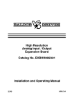
1.1
Display Section and Operation Keys on Operation
Panel
Figure 1.1 shows the operation panel of the SS400G MLSS converter.
There are a display section and operation keys on the panel. Six keys that can be seen through the
window of the front cover can be operated from the outside.
The area that can be seen through the front cover.
Liquid crystal display (LCD)
Operation level modes
Setting level/service
level modes
Status display
HOLD
TEMP. MAN
FAIL
Data display
Pointer display
UNIT / MODE
SUB MENU
mg/l
Message display
YES NO
ENT
Key operation display
YES
NO
MODE
MEASURE
CAL
SIMPLE CAL
WASH
DISPLAY
HOLD
SETPOINTS
RANGE
SET HOLD
WASH DATA
SERVICE
CONTAOTS
S1
ENT
S2
S3
FAIL
Operation key
Setting level selector
key
Lamps indicating
output of contact
signals
[YES] : Press when the flashing key operation display is relevant to “Yes”.
: Press when the flashing key operation display is relevant to “No”.
[NO]
[MODE] : Press when the mode is changed from measurement mode to operation level.
When in other than measurement mode, press this to stop operation.
: Press when keying in a digit in data setting.
[>]
: Press when keying in a numeral in data setting.
[Λ]
[ENT] : Press when entering a keyed-in data item.
Figure 1.1 Operation Panel
IM 12E6B1-02E
5th Edition : Apr.17, 2015-00
1-2
1.2
<1. Procedures for Key Operation>
Operating the MLSS Converter
Connecting the MLSS Sensor and Supplying Power
The SS400G MLSS converter operates on power supplied at a specified voltage. Before operation,
connect the MLSS sensor. Perform wiring by removing the front cover and terminal cover as shown in
Figure 1.2.
Sensor connection terminals: 11, 12, 13, 14, 14, 15, 17, 18 and 19
Power connection terminals: L1, L2
Power switch
Terminal cover
Grounding terminal
This is located on the bottom side of the case
Figure 1.2 External Wiring Connection Terminals
• When power is supplied to the converter, the converter starts up in measurement mode; the
data display indicates the MLSS concentration (unit: mg/l) and the message display, the output
current value. [Initial status]
• If the converter detects a failure, {FAIL} is displayed and an error code is displayed on the
message display. The <FAIL> indicator lamp also lights. If a failure occurs, refer to Section 8.2.
UNIT / MODE
YES
NO
FAIL
UNIT / MODE
mg/l
mg/l
MEASURE
CAL
SIMPLE CAL
WASH
DISPLAY
HOLD
MEASURE
CAL
SIMPLE CAL
WASH
DISPLAY
HOLD
MODE
CONTAOTS
YES
NO
MODE
S1
ENT
S1
S2
ENT
S3
FAIL
Example of normal display
CONTAOTS
S2
S3
FAIL
Example of display when a failure occurs
Figure 1.3 Example of Measurement Mode Display
IM 12E6B1-02E
5th Edition : Apr.17, 2015-00
1.3
1.3.1
1-3
<1. Procedures for Key Operation>
Basic Key Operation
Mode Selection at Operation Level (For details, see Section 5.3)
To check that external key operation can be performed normally, attach the front cover.
When selecting the mode, note the following three points:
• In an operation other than in the measurement mode, the mode returns to the measurement
mode when the [MODE] key is pressed.
• <HOLD> mode is skipped. [Default setting]
• If no key is operated for ten minutes or more, the mode changes to measurement mode. [Default
setting]
1.
Press the [MODE] key once. The display shown in Figure 1.4 (1) appears.
(1)
(2)
UNIT / MODE
UNIT / MODE
mg/l
YES NO
mg/l
MEASURE
CAL
SIMPLE CAL
WASH
DISPLAY
HOLD
The pointer to <CAL> and {YES} and {NO} in
the key operation section are flashing.
This indication means, “Do you want to
perform solution calibration?
Answer by pressing the [YES] or [NO] key.”
YES NO
MEASURE
CAL
SIMPLE CAL
WASH
DISPLAY
HOLD
This is the display when [YES] is pressed
in answer to the indication in (1).
As soon as the pointer stops flashing, the
message display changes to {VALUE} and
the next step is requested.
Figure 1.4 Example of Indication at Operating Level
2.
The screen in Figure 1.4 (1) is displayed when the [NO] key is pressed. Each time the [NO] key
is pressed, the display changes, and the request display for a different mode is displayed. After
completing one cycle, the display returns to that show in Figure 1.4 (1).
IM 12E6B1-02E
5th Edition : Apr.17, 2015-00
1-4
1.3.2
<1. Procedures for Key Operation>
Operation to Select Setting Level (For details, see Section 5.3.)
Select the setting level by removing the front cover. In the measurement mode, press the [*] key
(setting level selection).
(1)
(2)
UNIT / MODE
SUB MENU
UNIT / MODE
mg/l
MEASURE
CAL
SIMPLE CAL
WASH
DISPLAY
HOLD
YES NO
SUB MENU
mg/l
SETPOINTS
RANGE
SET HOLD
WASH DATA
SERVICE
MEASURE
CAL
SIMPLE CAL
WASH
DISPLAY
HOLD
YES NO
SETPOINTS
RANGE
SET HOLD
WASH DATA
SERVICE
This indicates the setting level/service
level.
The pointer to <SETPOINTS> and {YES} and {NO} of
the key operation section are flashing.
This indication means, “Do you want to change to the
alarm point setting mode?
Answer by pressing the [YES] or [NO] key.”
This is the display when the [YES] key is pressed in
answer to the indication in (1).
As soon as the pointer stops flashing, the message
display changes to {STEP.1} and the next step is
requested.
Figure 1.5 Example of Display at Setting Level
1.3.3
Operation to Enter Data
NOTE
Entered data are not cancelled even if the power is turned OFF. If temporary data are entered, enter
the normal fixed data again.
When [YES] is pressed for the display in Figure 1.5 (2), the display changes to that in Figure 1.6 (1).
In this display, changing the data value from the previously entered {195.0} to {50.0} is given as an
example.
(1)
Continue to press the [Λ] key until the flashing “1” changes to “0”.
(2)
Press the [>] key to cause the “9” to begin flashing, then use the [Λ] to select the number “5”.
(3)
Press the [>] key again to cause the rightmost “5” to begin flashing, then use the [Λ] key to enter
“0”.
(4)
Press the [ENT] key. The value of {50.0} is entered and the display returns to that in Figure 1.5
(1).
(1)
(2)
UNIT / MODE
SUB MENU
UNIT / MODE
mg/l
ENT
MEASURE
CAL
SIMPLE CAL
WASH
DISPLAY
HOLD
When the [YES] key is pressed in the
display in Figure 1.5 (2), the displays
changes to this display.
SUB MENU
mg/l
SETPOINTS
RANGE
SET HOLD
WASH DATA
SERVICE
ENT
MEASURE
CAL
SIMPLE CAL
WASH
DISPLAY
HOLD
SETPOINTS
RANGE
SET HOLD
WASH DATA
SERVICE
When the [ENT] key is pressed, the
displayed value is entered.
Figure 1.6 Setting the Data Display
IM 12E6B1-02E
5th Edition : Apr.17, 2015-00
1.3.4
1-5
<1. Procedures for Key Operation>
Operation to Enter Password
To prevent changing of setting data, passwords can be provided for each level of operation, setting
and service (selected from nine types). After passwords have been set, the display shown in Figure
1.7 (1) (password entry request) appears when data entry is attempted at the corresponding level.
When the unit is shipped from the factory, no passwords are set, thus the password entry request is
not displayed.
(1)
(2)
UNIT / MODE
SUB MENU
UNIT / MODE
mg/l
ENT
MEASURE
CAL
SIMPLE CAL
WASH
DISPLAY
HOLD
SUB MENU
mg/l
SETPOINTS
RANGE
SET HOLD
WASH DATA
SERVICE
ENT
MEASURE
CAL
SIMPLE CAL
WASH
DISPLAY
HOLD
SETPOINTS
RANGE
SET HOLD
WASH DATA
SERVICE
Note: Password 471 does not exist.
The display appears when the [MODE] key or [*] key
is pressed, or [YES] is pressed in response to a
{*SERVC} message.
Enter the set password and then press the [ENT] key.
If it is different from the setting, the display changes
back to the previous one (on the left).
Figure 1.7 Example of Password Entry Request Display and Entry Display
IM 12E6B1-02E
5th Edition : Apr.17, 2015-00
Blank Page
2.
2-1
<2. Overview>
Overview
This chapter gives an overview of the EXA ss series SS400 MLSS metering system and the
specifications for the SS400G MLSS converter.
2.1
2.1.1
EXA ss Series SS400 MLSS Metering System
SS300G MLSS Sensor
The SS300G MLSS sensor uses transmitted and scattered light comparison as the measurement
principle, covering a wide measurement range, from 500 mg/L to 20000 mg/L. Because this
measurement method is used, this sensor is not easily influenced by changes in light source, staining
or coloring. With additional specifications, jet cleaning equipment can be selected, providing the
means to establish a long-term stable measurement environment.
The SS300G emits near-infrared light to the measuring solution from a light emitting diode in the light
source, and converts absorbed and scattered light transmitted and scattered by suspended matter to
electric signals and passes it to the converter.
2.1.2
SS400G MLSS Converter
The SS400G MLSS converter compares and computes the transmitted and scattered light signals
received from the MLSS sensor and converts them to the MLSS concentration value. The obtained
MLSS concentration is displayed in digital form and also output as analog signals of 4 – 20 mA DC
(2-output available).
UNIT / MODE
HOLD
TEMP. MAN
SUB MENU
FAIL
mg/l
YES NO
ENT
YES
NO
MODE
MEASURE
CAL
SIMPLE CAL
WASH
DISPLAY
HOLD
SETPOINTS
RANGE
SET HOLD
WASH DATA
SERVICE
CONTAOTS
S1
ENT
S2
S3
FAIL
IM 12E6B1-02E
5th Edition : Apr.17, 2015-00
2-2
2.1.3
<2. Overview>
Holder and Other Equipment
Equipment configuring the MLSS metering system includes holders to support the MLSS sensor and
relay terminal box used if the distance between the sensor and converter is large, and the calibration
kit which includes all necessary items for solution calibration of MLSS metering.
Four types of holders can be used: guide holder, submersion type holder, well bucket type holder,
flow-through type holder, and float type holder. They are selected depending on the measurement
conditions.
IM 12E6B1-02E
5th Edition : Apr.17, 2015-00
2.2
2-3
<2. Overview>
Specifications for SS400G MLSS Converter
The SS400G MLSS converter uses the transmitted and scattered light method to more accurately
measure MLSS/SS concentration. It outputs an analog signal corresponding to the MLSS/SS
concentration and several contact signals, such as a high and low alarm.
This converter can be used in a wide variety of applications since it is provided with many operation
parameter setting functions. It also has several self-diagnostic functions, simplifying maintenance
work.
2.2.1
Standard Specifications
Measuring objects:
Note:
Concentration of mixed liquor suspended solids (MLSS) in an aeration
tank in a sewage or industrial wastewater treatment plant.
MLSS analyzer cannot be used for measurement of suspended solids (SS) concentration in effluent after aeration
treatment, neutralization facilities, and seawater.
When a guide-pipe type sensor is used in excreta disposal facilities, the cable must not come in contact with the liquid. Consult Yokogawa.
[Converter]
Measuring method:
Transmitted/scattered light comparison method
Measuring Range:
500 - 20000 mg/L
Output Signal: Two 4 - 20 mA DC signals; maximum load resistance: 600 Ω
• The range of mA 1 output can be switched by remote control.
• 22 ±0.5 mA (burnup) or 2 mA±0.5 mA (burndown) can also be selected as an output
current during failure.
• Both signals (setpoint or the most-recent value) can be retained during system
maintenance or cleaning.
• The range of concentration can be set separately for both of these signals.
Output range setting range:
Min. 0-1000 mg/L
Max. 0-20000 mg/L, (zero suppression can be set for readings up to
60% of the range, and span should be 1000 mg/L or more.)
Indication:
Main display section; LCD six-digit display (maximum reading; 99999.9 mg/L ;
effective digits; 3 digits, minimum reading; 0.1 mg/L)
Message display section; Six-digit alphanumeric display
Contact output: Types of alarm: S1, S2 and S3; alarm for upper/lower limits of concentration, HOLD,
cleaning
S4; FAIL alarm
Alarm actions: Configurable with on/off output, hysteresis and delay time
Type of contact: Relay (voltage-free)
Capacity: 100 VA maximum at 250 V AC, 2 A 50 W maximum at 30 V DC, 2 A
IM 12E6B1-02E
5th Edition : Apr.17, 2015-00
2-4
<2. Overview>
Table 2.1 Contact status
Contact status at power ON
Contact
Contact status
at power OFF
When not Activated
When Activated
S1
Open
Open
Closed
S2
Open
Open
Closed
S3
Open
Open
Closed
FAIL
Closed
Open
Closed
Contact Input: Functions: Remote range switching, cleaning start no-voltage contact
ON input resistance: 200 Ω or less
OFF input resistance: 100 kΩ or more
Ambient temperature: -10 to 55°C
Relative temperature:
10 to 90% RH (non-condensing)
Construction:
Complies with JIS C0920 watertight, IEC IP65 and NEMA TYPE 4X standards
Materials:
Casing; Molded aluminum alloy
Cover; Polycarbonate
Hood for sun protection (optional); Carbon steel or Stainless steel
Mounting bracket (optional); Stainless steel
Finish: Baked polyurethane coating (standard), or epoxy baked finish (optional)
Color: Casing; Frosty white (equivalent to Munsell 2.5Y8.4/1.2)
Cover; Deep sea moss green (equivalent to Munsell 0.6GY3.1/2.0)
Mounting:
JIS 50A pipe (2-inch), pipe -mounted, wall-mounted or panel-mounted
Power supply:
100 to 240 V AC, 50/60Hz, 24 V DC
Power consumption: 22 VA maximum (AC power), 5 W maximum (DC power)
Weight:
Approx. 2.5 kg
Dimensions:
144(W) x 144(H) x 135(D) mm
Cable Inlet:
Six places (including sensor port)
DIN PG13.5 or equivalent with plastic waterproof cap (cable diameter: 6 to 12 mm)
Cable terminal: Terminal size 0.13 to 4 mm2 (only pin terminal can be connected)
Conduit adapter (optional): G 1/2 female thread or 1/2NPT thread
Regulatory Compliance:
EMC Regulatory Arrangement in Australia and New Zealand (for /RCM option):
EN 55011 Class A, Group 1
Korea Electromagnetic Conformity Standard Class A
A급 기기 (업무용 방송통신기자재)
이 기기는 업무용(A급) 전자파적합기기로서 판매자 또는
사용자는 이 점을 주의하시기 바라며, 가정외의 지역에서
사용하는 것을 목적으로 합니다.
Self-diagnosis function:
Calibration error, Input voltage error
Setting value error
EEPROM write error
AD error, Memory error
Operation parameter setting function: (See Section 5.2)
[Characteristics]
Linearity:
Repeatability:
Stability:
±4.5% F.S (by stable kaolin solution)
2% F.S. (by calibration plate)
Zero ± 2% F.S./day (by city water)
Span ± 2% F.S./day (by calibration plate)
Note
F.S. means upper setting value of output range.
IM 12E6B1-02E
5th Edition : Apr.17, 2015-00
2.2.2
2-5
<2. Overview>
Model and Codes
Model
SS400G
—
Supply
voltage
Language for
cautionary notes or
other remarks
Suffix code
-------N
-1
-4
-J
-E
Options:
Bracket
Hood
Tag plate
Finish
Unit
Adapter for conduit installation
[Style : S2.2]
Option code
-------------------------------------------------
Description
MLSS Converter
Always "N"
100-240 V AC, 50/60 Hz
24 V DC *1
Japanese
English
/U
/PM
/H3
/H4
/SCT
/X1
/PPM
/AFTG
/ANSI
/SPS
Pipe or wall mounting (stainless steel)
Panel mounting (stainless steel)
Hood for sun protection (carbon steel)
Hood for sun protection (stainless steel)
With stainless-steel tag plate
Epoxy baked finish
Readings in ppm
G1/2 (female thread)
1/2NPT thread
With screws for salt protection *2
*1 NOT 2-wire system
*2 The SUS screws with teflon coating are used at four corners of the cover.
Accessories
Item
Part Number
Description
Spare fuse
Pipe mounting bracket
K9171SS
Attached when option code “/U” is specified.
Panel mounting bracket
K9171ST
Attached when option code “/PM” is specified.
Shading hood
K9663CA
Attached when option code “/H3” is specified.
K9663CC
Attached when option code “/H4” is specified.
Stainless tag plate
Y9412NP
Attached when option code “/SCT” is specified.
Conduit connection adapter
K9171SU
Attached when option code “/AFTG” is specified.
K9316AF
Attached when option code “/ANSI” is specified.
IM 12E6B1-02E
5th Edition : Apr.17, 2015-00
2-6
2.2.3
<2. Overview>
External Dimensions
Unit: mm
Hood (optional)
Option code : /H
Four M6 screws, 8 deep
184
220
80
72
20
144
80
23
144
112
Cable inlet port (21 dia. holes)
equivalent to DIN PG13.5 cable gland
A
B
C
A: Sensor cable inlet port
B: Contact input inlet port
C: Analog output cable inlet port
D: Contact (S1, S2), output cable inlet port
E: Contact (S3, FAIL), output cable inlet port
F: Power cable inlet port
36
D
E
36
F
38
F0201.ai
36
Ground terminal
(M4 screw)
Adapter for Conduit Installation (Option Code: /AFTG or /ANSI)
Packin
Case
Clanp claw
Cable gland
49
Adapter
Approx.
55
G1/2 screw (/AFTG)
1/2 NPT screw (/ANSI)
Figure 2.1 MLSS converter (1)
IM 12E6B1-02E
5th Edition : Apr.17, 2015-00
2-7
<2. Overview>
Pipe Mounting Bracket/Wall Mounting Bracket (Option code:/U)
Unit: mm
Example of bracket used for pipe mounting
188
M6, 4 screw
174
200
50
Nominal 50 mm (OD 60.5 mm)
mounting pipe
100
Example of bracket used for wall mounting
135
13
M6, 4 screw
224
200
35
15
70
10 mm dia. ,3 hole
100
Panel mounting bracket (option code: /PM)
23
12 max. (panel thickness)
M6, 4 screw
Panel cutout dimensions
137 +20
100
137 +20
178
Figure 2.2 MLSS converter (2)
IM 12E6B1-02E
5th Edition : Apr.17, 2015-00
Blank Page
3-1
<3. Installation and Wiring>
3.
Installation and Wiring
Install the SS400G MLSS converter where the operator can see the display and carry out key
operations.
This chapter describes the selection of an installation location and the procedures for mounting and
wiring.
3.1
Installation
3.1.1
Selection of Location
Install the SS400G MLSS converter where the following conditions are met.
•
Near the MLSS sensor
Consider the cable length of the sensor it is to be combined with (including the dedicated
extension cable).
•
No presence of corrosive gases
Corrosive gases are to be avoided because they may damage the electrical components in the
converter.
•
Little mechanical vibration
Vibration may loosen external wiring connections.
•
Normal temperatures, with little fluctuation
It is necessary for the temperature not to exceed a range of –10 to 55°C.
•
Humidity maintained between 10 to 90% RH
Avoid choosing a location likely to be exposed to abnormally high or low humidity over a
prolonged period. It is recommended that the converter be used in a location where the humidity
is between 25% and 85% RH.
•
No exposure to direct sunlight
Direct sunlight may abnormally raise the temperature in the converter. If direct sunlight cannot be
avoided, use a hood for shading (optional).
IM 12E6B1-02E
5th Edition : Apr.17, 2015-00
3-2
3.1.2
<3. Installation and Wiring>
Preparation for Installation
[Incorporation of Separate Attachments]
Optional parts specified with the option codes (hood, mounting bracket, conduit connection
adapter, etc.) are delivered as separate attachments.
To avoid misplacing these parts, it is recommended that you attach them before installation.
(For incorporation, refer to Subsections 2.2.3 and 3.1.3).
[Installation Provisions]
Make provisions to fix the SS400G MLSS converter so that it is installed in a position suitable
for easy operation.
(1) Pipe Mounting
The SS400G is fixed to a stanchion (pipe) with a U-bolt. Provide a rigid vertical pipe with an
OD of 60.5 mm (a horizontal pipe is also acceptable).
(2) Wall Mounting
Fix the SS400G with three M8 bolts (not supplied). Carry out drilling on the mounting surface
as shown in Figure 3.1.
Unit: mm
144
MLSS converter
144
102
35
70
Figure 3.1 Drilling for Wall Mounting
(3) Panel Mounting
Make a panel cutout as shown in Figure 3.2 in the mounting position.
Unit: mm
178
Width of mounting bracket
137
137
+2
0
+2
0
Figure 3.2 Cutout for Panel Mounting
IM 12E6B1-02E
5th Edition : Apr.17, 2015-00
3.1.3
3-3
<3. Installation and Wiring>
Converter Mounting
(1) Pipe Mounting
Figure 3.3 shows the pipe mounting bracket and the mounting procedure.
Bracket mounting screws
Converter
Bracket
Note: If a hood (see Figure 2.1) is
to be attached, fix it making
use of the two upper bracket
mounting screws.
Pipe mounting bracket
Nut (2 pcs)
U-bolt
Washers (2 pcs)
Stanchion (50 A pipe)
Figure 3.3 Pipe Mounting Procedure
(2) Wall Mounting
Figure 3.4 illustrates the wall mounting procedure.
Converter
Mounting hole (3 places)
M8 bolts (not supplied)
Provide bolts of a length
suitable for the mounting
holes.
Note: The same mounting bracket
and accessories as the pipe
mounting bracket are attached.
When mounting the converter
on the wall, use the bracket
only.
Bracket
Figure 3.4 Wall Mounting Procedure
(3) Panel Mounting
Figure 3.5 illustrates the panel mounting procedure.
Panel
Converter
Bracket
Mount the SS400G after
inserting it into the panel
cut opening.
Fixing screws (2 pcs)
Figure 3.5 Panel Mounting Procedure
IM 12E6B1-02E
5th Edition : Apr.17, 2015-00
3-4
<3. Installation and Wiring>
3.2
3.2.1
Wiring
Types of Wring for Converter
Implement the following types of wiring with the SS400G MLSS converter.
(1)
Wiring for high and low alarms (S1, S2, and S3 contact outputs) (refer to Subsection 3.2.3)
(2)
Wiring for cleaning (S1, S2, and S3 contact outputs)/failure (refer to Subsection 3.2.4)
(3)
Wiring for power supply (refer to Subsection 3.2.5)
(4)
Sensor cable (or extension cable) connection (refer to Subsection 3.2.6)
(5)
Wiring for output signal and remote function (contact input) (refer to Subsection 3.2.7)
(6)
Ground wiring (refer to Subsection 3.2.8)
Provide the power wiring system with a switch to halt power supply to the MLSS converter. Providing
the switch makes it safe to remove the connection from the converter for repair, etc. To start or stop
the MLSS converter during normal operation, use the power switch inside the converter.
Operation panel
Open the panel
by pulling on the
knob at the lower
right of the front
panel.
Sensor cable/output
signal wiring connection terminals
Contact output/power cord terminals
Terminal cover
Grounding terminal (M4 screw)
This is located on the bottom side of the case.
HIGH VOLTAGE Warning
Be careful not to touch the terminals (contact
output/power supply) in the cover while power is
being supplied. Perform wiring after cutting off
the power supply source (via a circuit breaker).
IM 12E6B1-02E
5th Edition : Apr.17, 2015-00
3-5
<3. Installation and Wiring>
[External Wring Cable Connection Terminal Diagram]
SS400G Converter
*3
Contact output S1
31
32
S1
mA1
S2
mA2
41
Contact output S2
42
*3
Contact output S3
51
52
71
Contact output FAIL
72
S3
FAIL
+
61
–
+
65
–
G
4 to 20mA DC
66
63
*1
22
25
R2
G
*2
4 to 20mA DC
62
21
R1
*1
Grounding terminal
(M4 screw)
26
23
*3
1
2
3
Contact input R2 (remote range switching)
Terminal box WTB10-SS1
11
11
11
12
12
12
13
13
13
14
14
14
Power supply
100 to 240V AC or
24V DC ±10%
Contact input R1 (remote cleaning)
*5
*6
L1 +
15
15
15
L2 -
16
16
16
17
17
17
18
18
18
19
19
19
G
*4
SENSOR
F0306_2.ai
*1: ALWAYS use a 6 to 12 mm OD. shielded cable.
*2: ALWAYS ground (grounding resistanace 100 Ω or less) the grounding terminal of the casing of the MLSS converter.
(Ground the power cord instead only if the above grounding is not feasible. Do NOT use two-point grounding).
*3: ALWAYS use a 6 to 12 mm OD. cable.
*4: Use the terminal box only if the MLSS converter is installed separately from the MLSS sensor.
(Normally, the box is unnecessary.)
*5: Specify this cable using the suffix code for a terminal box.
*6: For 24 VDC power supply, connect the "+" terminal to L1 and the "–" terminal to L2.
Figure 3.6 External Wiring Cable Connection Terminal and Diagram
Remove the front cover and open the panel by pulling on the knob found in the lower right corner of
the front panel.
Check that the power switch is set to OFF.
Remove the terminal cover and perform the following.
(1) Wiring for high and low alarms
(2) Wiring for cleaning/failure
(3) Wiring for power supply
Attach the terminal cover and perform the following.
(4) Sensor cable (or extension cable) connection
(5) Wiring for output signal and remote function (contact input)
Close the operation panel, attach the front cover and, in the last step, ground the unit.
IM 12E6B1-02E
5th Edition : Apr.17, 2015-00
3-6
3.2.2
<3. Installation and Wiring>
Cable Inlet Port
There are six cable inlet ports in the SS400G MLSS converter. These ports are provided with cable
glands conforming to a cable with an OD of 6 to 12 mm.
Introduce each cable gland through each port as specified in Figure 3.7. If there is a cable inlet port
that is not used, seal the opening to keep dust from getting in.
Cable inlet port
Equivalent to cable gland DIN PG13.5
A
B
C
A: Sensor cable inlet port
B: Remote input inlet port
C: Analog output cable inlet port
D: Contact (S1, S2), output cable inlet port
E: Contact (S3, FAIL), output cable inlet port
F: Power cable inlet port
36
D
E
36
Ground
terminal (M4 screw)
Unit: mm
F
38
36
F0307.ai
Figure 3.7 Specified Application of Cable Inlet Ports
If a cable is protected with a conduit, use an adapter (5 sets are supplied when option code “/AFTG
is specified). Remove the cable glands from the B, C, D, E, and F ports and attach the adapters and
adapter cable glands (provided as accessories) in place of the above cable glands as shown in Figure
3.8.
No conduit work is done with sensor cable inlet port A. Use the cable gland that was attached on
delivery without removing it.
CAUTION
Be sure to use the WTB10-SS1 relay terminal box if it is necessary to protect all the wiring cables to
the converter with conduits.
The cable (dedicated extension cable) between the relay terminal box and converter can be protected
with a conduit. In this case, the adapter is attached to the relay terminal box (specification is required).
Packing
Case
Unit: mm
Clamp claw
Cable gland
49
Approx. 55
Adapter
G1/2 screw (/AFTG)
1/2 NPT screw (/ANSI)
F0308.ai
Figure 3.8 Conduit Connecting Adapter
IM 12E6B1-02E
5th Edition : Apr.17, 2015-00
3.2.3
3-7
<3. Installation and Wiring>
Wiring for Contact Output S1 and S2
This wiring is to output the contact outputs S1 and S2 as the contact for high and low alarms, hold,
and cleaning. The ratings of this contact output relay contact (N.O) are as follows.
• Maximum allowable voltage:250 V AC, 30 V DC
• Maximum allowable current: 2 A
• Maximum allowable power: 100 VA (AC), 50 W (DC)
Use equipment to be connected that satisfies the above conditions.
Note: Contacts S1 and S2 for contact output must be “open” when deenergized.
[Cable to Be Used]
Use a cable with a finished OD of 6 to 12 mm. Select 2 or 4 conductors depending on the
number of signals.
[Connecting Procedure]
(1) End-treat the cable.
Strip off about 40 mm of the cable insulation covering from the cable end and
attach crimping terminal lugs conforming to terminal size 0.13 to 4 mm2 to the end of each
conductor.
(2) Connect each cable conductor to the specified terminals
Terminal 31 and 32: conductors for contact output S1
Terminal 41 and 42: conductors for contact output S2
When the cable is introduced into the converter, remove the assembled parts from the
cable gland body located at cable inlet port E and pass the cable through these parts in
the proper order.
(3) Fix the cable.
Adjust the cable length required in the converter and fix the cable by mounting the parts
through which the cable passes to the cable gland body.
3.2.4
Wiring for Contact Output S3 and FAIL
This wiring is to output the contact output S3 as the contact for high and low alarms, hold and
cleaning.
For contact output FAIL, a failure signal is output if the converter detects a failure.
The wiring is done if these contact signals are used.
The rating of contact output FAIL is the same as for contact outputs S1, S2 and S3.
Note: When the power is OFF, the contact for contact output FAIL is “closed”.Contact S3 is "open" when the power is off.
[Cable to Be Used]
Use a cable with a finished OD of 6 to 12 mm. Select 2 or 4 conductors depending on the
number of signals.
[Connecting Procedure]
(1) Terminate the cables.
Strip off about 40 mm of the cable insulation covering from the cable end and attach
crimping terminal lugs conforming to the terminal size 0.13 to 4 mm2 to the end of each
conductor.
(2) Connect each cable conductor to the specified terminals
Terminal 51 and 52: Conductors for contact output S3
Terminal 71 and 72: Conductors for contact output FAIL
When the cable is introduced into the converter, remove the assembled parts from the
cable gland body located at cable inlet port D and pass the cable through these parts in
the proper order.
IM 12E6B1-02E
5th Edition : Apr.17, 2015-00
3-8
<3. Installation and Wiring>
(3) Fix the cable.
Adjust the cable length required in the converter and fix the cable by mounting the parts
through which the cable passes to the cable gland body.
3.2.5
Wiring for Power Supply
Supply AC power of 85 to 264 V AC, 50/60 Hz or DC power of 24 V DC±10%. Use a power supply that
does not experience voltage fluctuation or exceed the usable range.
CAUTION
For safety maintenance work:
To avoid electric shock or equipment damage, be sure to provide a switch (double-pole type) in the
power supply wiring to interrupt the supply of power to the MLSS converter.
[Cable to be Used]
Use a two-conductor cable with a finished OD of 6 to 12 mm.
[Connecting Procedure]
(1) Terminate the cable.
Strip off about 40 mm of the cable insulation covering from the cable end and attach
crimping terminal lugs conforming to the terminal size 0.13 to 4 mm2 to the end of each
conductor.
(2) Connect each cable conductor to specified terminal 1 and 2.
When the cable is introduced into the converter, remove the assembled parts from the
cable gland body located at cable inlet port F and pass the cable through these parts in
the proper order.
(3) Fix the cable.
Adjust the cable length required in the converter and fix the cable by mounting the parts
through which the cable passes to the cable gland body.
When connection is made to the external wiring terminals explained in Subsection 3.2.3 and 3.2.5,
attach the terminal cover.
3.2.6
Sensor Cable (or Dedicated Extension Cable) Connection
Ordinarily, the sensor cable is connected directly to the converter. If the WTB10-SS1 relay terminal
box is used, do the wiring by connecting the sensor cable to this relay terminal box and using the
dedicated extension cable (attached to the WTB10-SS1 relay terminal box) between the relay
terminal box and the converter. The ends of the sensor cable and dedicated extension cable already
are finished.
Note: If a dedicated extension cable is to be used, connect it after examining both ends because the end treatment may differ at the
cable end on the relay terminal box side and on the converter side.
[Connection Procedure]
(1) Connect each conductor of the cable to the predetermined terminals of 11 to 19.
When the cable is introduced into the converter, remove the assembled parts from the
cable gland body at the cable inlet port A and pass the cable through these parts in the
proper order.
(2) Fix the cable.
Adjust the cable length required in the converter and fix the cable by mounting the parts
through which the cable passes to the cable gland body.
IM 12E6B1-02E
5th Edition : Apr.17, 2015-00
3.2.7
3-9
<3. Installation and Wiring>
Wiring for Output Signal and Remote Cleaning Start Instruction
This is wiring for transmitting the converter’s output signal to a receiving instrument, such as a
recorder, and for sending a contact input signal.
There are two signals, output 1 and 2 (4-20 mA DC)
The wiring for the contact input signal is done only when the remote cleaning or remote range
switching is performed.
The ON/OFF contact input can be identified with input resistances (ON: 200Ω or less for more than
0.06 second; OFF: 100 kΩ or more). Use a dry contact.
[Cable to Be Used]
Use a shielded cable with a finished OD of 6 to 12 mm. Select 2, 4, or 6 conductors
depending on the number of signals.
[Connection Procedure]
(1) Terminate the cable.
Strip off about 40 mm of the cable insulation covering from the cable end.
Cut the exposed shield at its root near the remaining covering and solder a grounding
eadwire (about the same length as the cable conductors) to the shield.
Protect the soldered point by, for example, wrapping with insulation tape.
Next, attach crimping terminal lugs conforming to terminal size 0.13 to 4 mm2 to the end of
the leadwire and each conductor.
(2) Connect each cable conductor to the specified terminals.
Output 1 (mA1): Terminals 61 (+), 62 (-)
Output 2 (mA2): Terminals 65 (+), 66 (-)
Ground lead wire: Terminal 63
Remote cleaning contact input (R1): Terminals 21, 22
Remote range contact input (R2): Terminals 25, 26
CAUTION
The cable shield must be grounded at the converter side only.
When the cable is introduced into the converter, remove the assembled parts from the
cable gland body at the cable inlet port B or C and pass the cable through these parts in
the proper order.
(3) Fix the cable.
Adjust the cable length required in the converter and fix the cable by mounting the parts
through which the cable passes to the cable gland body.
IM 12E6B1-02E
5th Edition : Apr.17, 2015-00
3-10
3.2.8
<3. Installation and Wiring>
Grounding Wiring
The grounding terminal is located on the left side of the case as shown in Figure 3.9.
Ground the terminal using a wire having a nominal cross section of 2 mm2 or more, complying with
D grounding (the ground resistance must be 100 Ω or less). The terminal screw size is M4. Attach a
crimping terminal lug matching the M4 screw to the end of the wire.
Grounding terminal
(M4 screw)
Grounding wire
(nominal cross section of 2 mm2 or more)
Figure 3.9 Grounding Terminal
CAUTION
If grounding cannot be done from the converter case, do it on the power supply side using the power
cable conductor. In this case, use a three-conductor cable or a two-conductor shielded cable for the
power cord and connect one of three conductors or the shield to terminal 3 (for grounding) in the
converter.
IM 12E6B1-02E
5th Edition : Apr.17, 2015-00
4.
4-1
<4. Operation>
Operation
This chapter describes operation of the SS400 MLSS metering system, mainly the operating
procedures for the SS400G MLSS converter.
4.1
Operating Arrangements
Arrange all equipment composing the SS400 MLSS metering system for operation. For details on
equipment other than the MLSS converter, see the instruction manual for each individual piece of
equipment.
4.1.1
Inspection of Installation and Piping and Wiring
[Inspection of Installation]
• Check that the MLSS sensor and holder are firmly secured.
• Check that all unused cable inlet ports are sealed with, for example, a plug.
[Inspection of Wiring]
• Check that all necessary wiring has been completed and the cables are properly connected.
• After checking the connection to the MLSS converter, be sure to mount the terminal cover.
[Inspection of Piping]
• Piping is implemented only if a holder with a jet cleaner is used.
• Check that the cleaning utility (water/air) is supplied at sufficient pressure during cleaning
operation.
4.1.2
Supply of Power
Turn the power switch ON to start operation of the MLSS converter. Supplying the power operates the
converter in measurement mode.
[Main Operation in Measurement Mode (with factory default parameters)]
• The MLSS/SS concentration (mg/l) appears in the data display and the current value of
output 1 appears in the message display.
• Output signals of 4 to 20 mA DC corresponding to the MLSS/SS concentration are output.
• When the MLSS/SS concentration exceeds 20000 mg/l, contact output S1 is output (contact
“closed”). If the concentration becomes 0 mg/l or less, contact output S2 is output.
• If the MLSS converter detects a failure, contact output FAIL is output (contact “closed”).
Note: While the power is turned off, contact for contact output FAIL is “closed”.
IM 12E6B1-02E
5th Edition : Apr.17, 2015-00
4-2
4.1.3
<4. Operation>
Checking the Setting Parameters and Changing the Default Values
Set up relevant parameters to meet individual operating conditions. Also, confirm that important
parameters are correctly set even if the factory default parameters are to be used.
If default values have been changed, the data should be recorded; it is recommended that the data be
recorded in the “Worksheet for Operation Parameter Settings” included at the end of this manual.
The types and operations of setting parameters are detailed in Chapter 5. Read them before carrying
out setting. For reference the pages describing the main setting parameters and key operations are
shown below.
[Key operation Procedure]
Basic patterns of key operation (page 1-3)
Switching to the operation level/setting level
(pages 1-3 and 1-4)
Selection of numeric values and digits (data entry) (page 1-4)
Setting operation abortion (return to measurement mode) (page 5-1)
Development of setting items in the setting level (page 5-4)
Selection of setting parameters in the service level (page 5-17)
Password input (pages 1-5 and 5-34)
[Output Signal] Output range setting mode (page 5-13)
Hold parameter setting mode (page 5-14)
Output signal burn-out function setting mode (at FAIL occurrence) (page 5-29)
Time constant setting mode (page 5-29)
4.1.4
[Contact Output]
Automatic cleaning parameter setting mode
Alarm point setting mode Delay time and hysteresis setting mode (page 5-15)
(page 5-12)
(page 5-31)
[Combination MLSS Sensor Specifications]
Sensor constant setting mode Table selection mode for measurement (page 5-18)
(page 5-21)
Calibration
The MLSS and SS differ depending on the characteristics of the measuring solution; no reference
materials are used. Therefore, for accurate measurement of MLSS concentration, perform calibration
according to the procedure below.
(1) Set the measuring table
The SS400 MLSS metering uses kaolin, which is correlative with MLSS/SS as the reference
material. The SS400G MLSS converter contains a measuring table that uses kaolin
manufactured by us as the reference. In addition to this kaolin table, a measuring table for fly
ash of dust standard materials and a user measuring table are also included. These tables
can be selected as required. For normal conditions, use the default kaolin measuring table.
Note: The MLSS/SS value measured after calibrating the converter based on a dust substance (fly ash) is about twice
the value produced when kaolin-based measurement is carried out. To carry out kaolin-based measurement,
select “0” for the service level’s CODE04. Then, define the sensor constants using CODE01 and initialize the
calibration table.
(2) Set the sensor constant
The characteristics of the SS300G MLSS sensor deviate slightly for each sensor.
Each SS300G MLSS sensor has a sensor constant to correct this variation. Set a sensor
constant of the sensor to the MLSS converter.
Note: The sensor constant is indicated on the label affixed on the sensor table.
IM 12E6B1-02E
5th Edition : Apr.17, 2015-00
<4. Operation>
4-3
(3) Solution calibration (three-point calibration)
Normally, MLSS/SS differs because of characteristics (composition of suspended material,
size or color) of the measuring solution. Therefore, using the measuring solution to perform
solution calibration (three-point calibration).
It is recommended that solution calibration be performed when starting up operation.
Note:
Solution calibration is performed in such a way that sensitivity is adjusted at three points using the measuring
table contained in the converter.
(4) Simple calibration
After performing solution calibration, it is necessary to perform periodic calibration in order to
obtain stable measurement over a long period of time. Simple calibration (one-point
calibration) using a calibration plate for easy calibration. If the error of the measured value
exceeds the allowable range after simple calibration, the characteristics of the measuring
solution might have changed. In that case, perform solution calibration.
See Chapter 6 for calibration procedures; calibration-related parameters are explained in this
section.
[Setting Parameters Concerning Calibration]
CODE 01
Sensor constant setting mode CODE 04
Measuring table selection CODE 05
Display maximum setting mode CODE 06
Measured signal read mode CODE 22
Calibration table value setting mode
CODE 23
Calibration table initialization mode
4.1.5
(page 5-18)
(page 5-21)
(page 5-23)
(page 5-24)
(page 5-27)
(page 5-27)
Operation Check
After calibration is completed, return the MLSS sensor to installed operation status, then operate the
entire loop composing equipment. Continue a test run for a while and after confirming that there are
no faulty points place the system in steady operation.
IM 12E6B1-02E
5th Edition : Apr.17, 2015-00
4-4
4.2
<4. Operation>
Steady Operation
Normally, it is not necessary to adjust the SS400G MLSS converter except for periodic calibration. In
principle, check and maintain the sensor when calibration is implemented.
4.2.1
Measures for Failure Occurrence
If the SS400G MLSS converter detects a failure, FAIL contact output is output. If the burnout function
is active, the output signal causes burnout (2 mA or 22 mA). The content of the failure is given in the
data display through an error number.
If a failure occurs, confirm its contents and quickly take measures. See Section 8.2 for details on
failures.
4.2.2
Inspection and Maintenance
Calibrate MLSS metering during a time when the measured value error does not exceed the allowable
range. A period of one or two months is a guide.
Also, wipe the MLSS sensor or wetted part of the holder at the time of calibration.
4.2.3
Precautions When Measuring Low Concentration Levels
Air bubbles and dirt that disturb normal measurement readily stick to the MLSS sensor’s window if the
solution under measurement is flowing fast. Care must be taken since these can sometimes result in
large measurement errors especially when low concentration levels are being measured.
If the available flow-rate is unavoidably low (less than 20 cm/s), the optional jet cleaner should
be used. When carrying out calibration based on the actual test solution of a low concentration
measurement, clean the sensor completely of all dirt so that the calibration liquid (especially zeropoint calibration liquid) is not affected.
4.3
4.3.1
Operation Shutdown and Re-starting
Measures for Shutdown
Data set in the converter are retained even if the power is turned OFF.
If the operation is shutdown over a prolonged period, turn the power OFF.
If the MLSS sensor is dismounted, thoroughly remove any dirt from the sensor.
4.3.2
Measures for Re-starting
When the power is turned on again, the MLSS converter enters the measurement mode.
It takes several minutes for the sensor operation to stabilize after the converter is turned on. As an
output signal during this period does not indicate the correct MLSS value, be careful with control if
executed.
Perform calibration after operation is fully stabilized.
IM 12E6B1-02E
5th Edition : Apr.17, 2015-00
5.
5-1
<5. Parameter Setting>
Parameter Setting
When the SS400G MLSS converter is to be used, set data and select functions according to its usage
and the measurement conditions.
This chapter describes the setting procedures for parameters.
5.1
5.1.1
Summary of Setting Operations
Operation, Setting, and Service Levels
Parameter setting is carried out after selecting the relevant mode. These modes are classified into
three levels: operation, setting, and service.
[Operation Level]
This is basically the level to operate daily inspection and /or maintenance such as calibration
and/or manual cleaning. Only in this level can key operations be carried out externally with the
front cover mounted. At this level, items to be displayed on the message display can be
selected.
[Setting Level]
There are modes at this level for setting data related to output signals and contact outputs.
[Service Level]
The SS400G MLSS converter has various functions. At this level, there are modes to select
the functions necessary for operation.
5.1.2
Key Operation
Key operation can be carried out in the form of interactions. Operate keys according to the display in
the data display or the message display, pointer (mode indication) display positions, and /or display in
the key operation display.
For basic key operations, see Chapter 1.
[Interactions]
• Pointer flashing display
This inquires whether the indicating mode is entered or the pointer is moved to the next
mode.
When the modes at the setting or service level are to be indicated, an asterisk (*) is
indicated at the head of the message display. When a mode is entered, the pointer display
stops flashing and remains continuously lit.
• Flashing display of the key operation display
Select the relevant indicated presentation and press the corresponding key.
• Flashing display of data display (numerals)
This inquires whether the flashing numeral is changed or the flashing digit is moved.
Press the relevant key. If neither item to be selected is necessary, press the [ENT] key.
[Aborting a Setting]
Press the [MODE] key.
Normally, the [MODE] key is used to move the measurement mode to a mode at the
operation level; however, it is also used to return to measurement mode from some other
mode.
When the [MODE] key is pressed in other than measurement mode and if the output
signal hold function is being executed, the converter goes into “hold selection” mode.
IM 12E6B1-02E
5th Edition : Apr.17, 2015-00
5-2
<5. Parameter Setting>
(1) Hold selection mode display
(2) Measurement mode display
UNIT / MODE
HOLD
YES NO
UNIT / MODE
mg/l
mg/l
MEASURE
CAL
SIMPLE CAL
WASH
DISPLAY
HOLD
MEASURE
CAL
SIMPLE CAL
WASH
DISPLAY
HOLD
In “hold selection” mode, the display in the
message display and {YES} and {NO} in the
key operation display flash. If the current
status is “hold”, {HOLD} is also displayed.
In the display shown in (1), if the [YES] or
[NO] key is pressed, the mode changes to
measurement mode.
Figure 5.1 Display when the [MODE] Key is Pressed in a Mode Other Than Measurement Mode
[Automatic Return to Measurement Mode]
If no key operation is performed for 10 minutes, the converter automatically returns to
measurement mode. However, if it is in calibration mode, the converter automatically
returns to measurement mode in one hour.
This automatic return is not effective if the function has been set to “Shutdown”.
(See Service Level CODE 50.)
5.1.3
Points to Be Noted When Implementing Settings
(1) Password
If a password is set, the converter cannot enter a mode until the correct password is entered.
A “password entry request” is issued at the following times:
• Operation level: When the [MODE] key is pressed in measurement mode
• Setting level: When the [*] key is pressed in measurement mode
• Service level: When the [*SERVC] key is pressed on the message display
(2) Related items
When a data item is changed, check its relationship to the data set in other modes so that
there is no inconsistency.
[Items to check when the Output Range is Changed]
a. High and low alarm values and contact output hysteresis
[Items to check when High and Low Alarm Values are Changed]
a. Output range
b. Function setting of contact outputs S1, S2, and S3
c. Delay time and hysteresis
IM 12E6B1-02E
5th Edition : Apr.17, 2015-00
5.2
5-3
<5. Parameter Setting>
Setting Item List
Sections 5.2.1 to 5.2.3 show the setting item lists for each level.
5.2.1
Setting Items at Operation Level
[Operating level]
Table 5.1 Setting Items at Operation level
Mode/Setting Item Message display
Setting Contents
Default value Page
CAL (solution
calibration)
CALIB
P.6-3
SIMPLE CAL
(simple calibration)
S.CAL
P.6-5
WASH (manual
cleaning)
WASH START or STOP
DISPLAY
(indication selection
in message display)
*1
P.5-9
DISP
P.5-9
XX.XmA.1 Indication of output value of current output 1
(unit: mA)
XX.XmA.2 Indication of output value of current output 2
(unit: mA)
RELX.XX Software version indication
RNG_A/RNG_B Selection range indication for remote range
switching
*2
Alarm setting
SETP Same as the function of the alarm point
setting at the setting level.
HOLD
(output signal hold
selection)
HOLD [YES] key: Hold during measurement
[NO] key: No hold during measurement
*4
*3
Current
output
1 indication
Function stop
P.5-10
Function stop
P.5-14
*1: Cleaning is selected with any of the codes between CODE 40 and 42; this is displayed only when
the automatic cleaning execution in the automatic cleaning parameter setting has been selected.
*2: This is displayed when the remote range switching function has been set to 1 (execution).
“When RANGE_A is indicated, the setting range of output range setting 1 is output.
When RANGE_B is indicated, the setting range at service level CODE 31 is output.
*3: This is displayed when the hold function of SET HOLD at the setting level is being executed
(H.ON).
*4: This is displayed when “Execute” has been set for CODE 51.
Note: • A mode whose function stops is skipped.
• The alarm point changing mode is set for CODE 51 at the service level.
Remarks: The item in the display column appears in the message display.
An X in the display column indicates an unspecified numeral only.
IM 12E6B1-02E
5th Edition : Apr.17, 2015-00
5-4
5.2.2
<5. Parameter Setting>
Setting Items at Setting Level
[Setting level]
Table 5.2 Setting Items at Setting Level
Mode/Setting Item
Message display
RANGE
SET HOLD
Setting Contents
* SETP
SETPOINTS Alarm point setting for contact output
Default value
(See page 5-12)
Alarm point setting for contact output 1
* MLSS1 –0100.0 to 99999.9 (mg/l) *1 20000.0(mg/l)
Alarm point setting for contact output 2
* MLSS2 –0100.0 to 99999.9 (mg/l) *1 00000.0(mg/l)
Alarm point setting for contact output 3
* MLSS3 –0100.0 to 99999.9 (mg/l) *1 00000.0(mg/l)
Output range setting
* RANGE
*2
(See page 5-13)
Zero point setting for output 1
* 0% 00000.0 to 99999.9 (mg/l)
00000.0(mg/l)
Span point setting for output 1
* 100% 00000.0 to 99999.9 (mg/l)
05000.0(mg/l)
Zero point setting for output 2
* 0% 00000.0 to 99999.9 (mg/l)
00000.0(mg/l)
Span point setting for output 2
* 100% 00000.0 to 99999.9 (mg/l)
10000.0(mg/l)
Hold parameter setting
* HOLD
(See page 5-14)
Selection of hold function
execution/stop
* H.ON or * H.OFF * H.ON (execute)
* H.OFF (stop)
* H.OFF (stop)
* H.LST or * H.FIX * H.LST (immediately before
* H.LST
Selection of immediately before
or fixed value
*3
Fixed value setting for output 1
*4
* H.mA1 3.9 to 20.5 [mA]
12.0 [mA]
Fixed value setting for output 2
*4
* H.mA2 3.9 to 20.5 [mA]
12.0 [mA]
* WASH
(See page 5-15)
WASH DATA Parameter setting for automatic
cleaning
*5
* W.ON * W.ON (execute)
* W.OFF (stop)
Selection of cleaning execute/stop
Setting of cleaning period
value)
* H.FIX (fixed value)
*6
* tI.hr 00.1 to 12.0 [time]
(immediately
before value)
* W.OFF (stop)
1.0 [time]
Setting of relaxation time
*6
* tR.min 0.1 to 9.9 [min.]
0.5 [time]
Selection of cleaning method
*6
W.TYPE 0: jet cleaning
1: wiper cleaning
0: jet cleaning
Setting of cleaning period
*7
* tW.min 0.1 to 9.9 [min.]
0.5 [min.]
Setting of number of times
cleaning is executed
*8
* COUNT 1 to 5 [time]
1 [time]
*1:
This can only be set for high and low alarm (see CODE 40 to 42).
*2:
The minimum range is 0 to 1000 (mg/l). Set so that the absolute value of the difference between
two values becomes 1000 mg/l or more so that the smaller value is 60% or less of the larger
value.
Note: The setting range of the output range is different from the measuring range.
*3:
When the hold function has been set to stop (H.OFF), this item is skipped.
*4:
When the hold value is the immediately proceeding value (*H.LST), this item is skipped.
*5:
When “Cleaning” has not been set in the setting for contact S1, S2 and S3, this item is skipped.
*6:
When automatic cleaning has been set to “Stop”, this item is skipped.
*7:
When automatic cleaning has been set to “Stop”, this item is skipped.
When the cleaning method has been set to “Wiper”, this item is skipped.
*8:
When the automatic cleaning has been set to “Stop”, this item is skipped.
When the cleaning method has been set to “Jet”, this item is skipped.
IM 12E6B1-02E
5th Edition : Apr.17, 2015-00
5.2.3
5-5
<5. Parameter Setting>
Setting Items for Service Level
At the service level, each setting mode is selected by specifying the relevant code numbers.
Table 5.3 Setting Items at Service Level (1/3)
Mode/Setting Item
Message display
Setting Contents
Default value
CODE01
(See page 5-18)
Sensor constant 1
* S_1 0.00000 to 99999.9
0.00370
Sensor constant 2
* S_2 0.00000 to 99999.9
0.14545
Sensor constant 3
* S_3 0.00000 to 99999.9
2.4734
Sensor constant 4
* S_4 0.00000 to 99999.9
23.598
Sensor constant 5
* S_5 0.00000 to 99999.9
44.770
CODE02
(See page 5-19)
Voltage display during scattered light ON
* J1_ON (Display only, unit: V)
Voltage display during scattered light OFF
* J1_OF (Display only, unit: V)
Voltage display during transmitted light ON
* J2_ON (Display only, unit: V)
Voltage display during transmitted light OFF
* J2_OF (Display only, unit: V)
Scattered light current display
* J1_µA (Display only, unit: µA)
Transmitted light current display
* J2_µA (Display only, unit: µA)
J1/J2 display
* J1/J2 (Display only, unit: none)
CODE03
(See page 5-20)
Selection of various check function
execution
Selection of LED error detection (E1)
Calibration point interval error (E4)
* CHECK X1. X2. X3
X1=0 (stop) or 1 (execute)
X2=0 (stop) or 1 (execute)
X3=0 (stop) or 1 (execute)
1.1.1
0% point error (E5)
CODE04
(See page 5-21)
Selection of measuring table
* TABLE 0: kaolin
1: fly ash
2: user
0: kaolin
*1
CODE05
(See page 5-23)
Setting of display maximum value
* 100% 00000.0 to 99999.9 [mg/l]
CODE06
20000.0 [mg/l]
(See page 5-24)
Measured signal read
* 100%
* 67%
* 44%
* 30%
* 0%
CODE07
(See page 5-25)
Signal check
* PLATE Display only
CODE08
(See page 5-26)
Selection of bubble measure execution
Setting of limit value
* SPIKE 0: stop
1: execute
0: stop
* LIMIT 00000.0 to 99999.9 [mg/l]
100
Setting of hold time
* HLD_T 001 to 600 [sec.]
30 [sec.]
Setting of sampling time
* SMP_T 001 to 600 [sec.]
30 [sec.]
*1:
When 2 (user) is selected, CODE 05 and 06 should be set.
IM 12E6B1-02E
5th Edition : Apr.17, 2015-00
5-6
<5. Parameter Setting>
Table 5.3 Setting Items at Service Level (2/3)
Mode/Setting Item
Message display
Setting Contents
CODE22
Default value
(See page 5-27)
Setting of calibration table X axis 0% point
* IN_0 –1000.0 to 99999.9 [mg/l]
0000.0 [mg/l]
Setting of calibration table X axis 50%
point
* IN_1 00000.0 to 99999.9 [mg/l]
10000.0 [mg/l]
Setting of calibration table X axis 100%
point
* IN_2 00000.0 to 99999.9 [mg/l]
20000.0 [mg/l]
Setting of calibration table X axis 100%
point
* OUT_2 00000.0 to 99999.9 [mg/l]
20000.0 [mg/l]
CODE23
(See page 5-27)
* C.DEF
Initialization of calibration table
CODE30
(See page 5-28)
* REMOT 0: stop
1: execute
Selection of remote range switching
execution
CODE31
0: stop
*2
(See page 5-28)
Zero point setting for RANGE-B
* 0% 00000.0 to 99999.9 [mg/l]
00000.0 [mg/l]
Span point setting for RANGE-B
* 100% 00000.0 to 99999.9 [mg/l]
10000.0 [mg/l]
CODE32
Selection of burn-out function
(See page 5-29)
* BURN X1. X2
X1 (output 1) = 0 to 2 *3
X2 (output 2) = 0 to 2 *3
CODE37
Setting of time constant
(See page 5-29)
* DAMP
060 [sec.]
CODE40
Setting of contact output S1 function
(See page 5-30)
* S1 0: stop
1: low
2: high
3: hold
4: cleaning
2: high
CODE41
Setting of contact output S2 function
(See page 5-30)
* S2 0: stop
1: low
2: high
3: hold
4: cleaning
1: low
CODE42
Setting of contact output S3 function
(See page 5-31)
* S3 0: stop
1: low
2: high
3: hold
4: cleaning
4: cleaning
CODE44
Setting of delay time of alarm contact output
Setting of hysteresis of alarm contact
output
(See page 5-31)
* D.TIME
000 [sec.]
* HYST
00025.0 [mg/l]
CODE47
(See page 5-32)
Selection of alarm time out execution
* EXPIR
Setting of alarm time out time
* tE.min
0: stop
15.0 minutes
CODE50
Setting of measurement mode automatic
return
0.0
(See page 5-33)
* RET
1: execute
Table 5.3 Setting Items at Service Level (3/3)
IM 12E6B1-02E
5th Edition : Apr.17, 2015-00
5-7
<5. Parameter Setting>
Mode/Setting Item
Message display
Setting Contents
CODE51
Default value
(See page 5-33)
Selection of alarm point setting execution
* MODE
0: stop
CODE52
(See page 5-34)
Setting of password
* PASS
0.0.0
CODE53
(See page 5-35)
Selection of error detection operation
* Err.01 0: SOFTFAIL
1: HARDFAIL
1: HARDFAIL
* Err.08
* Err.09
* Err.22
CODE54
(See page 5-36)
Setting of minus measured value not displayed
*2:
* MINUS 0: stop (minus display given) 0: stop
1: execute (minus display
not given)
This setting is effective only when the remote range switching is ON and remote contact is
closed.
The minimum range is 0 to 1000 [mg/l]. Set so that the absolute value of the difference between
two values becomes 1000 mg/l or more so that the smaller value is 60 % or less of the larger
value.
Note: The setting range of the output range is different from the measuring range.
*3:
0: no burnout
1: 2 ± 0.5 mA
2: 22 ± 0.5 mA
*4:
X1 is an operation level setting
X2 is a setting level setting
X3 is a service level setting
IM 12E6B1-02E
5th Edition : Apr.17, 2015-00
5-8
5.3
<5. Parameter Setting>
Setting Procedures
Setting procedures are explained in the following order.
• Operation level
• Setting level
• Service level
5.3.1
Parameter Setting at Operation Level
Operation modes include various calibrations and manual cleaning at the operation level.
Here, operation procedures in each mode at the operation level are described in paragraphs (1) to (4).
The calibration operation mode (CAL, SIMPLE.CAL) is explained in Chapter 6.
Measurement
mode
[MODE]
[YES]
CALIB
[NO]
S.CAL
[NO]
*1
WASH
[NO]
DISP
[NO]
*2
SETP
[NO]
*3
HOLD
Solution calibration mode
HOLD
*1
[YES]
Simple calibration mode
HOLD
*1
[YES]
Manual cleaning mode
HOLD
*1
[YES]
[YES]
Selection mode for indication in the
message display
Alarm point setting mode
HOLD
*1
[YES]
Output signal hold selection mode
[NO]
*1: If the automatic cleaning function has been set to “Stop” in the automatic cleaning parameters setting mode, this is skipped.
*2: When CODE 51 has been set to “Stop”, this is skipped.
*3: When the hold function in “Hold parameter setting mode” at the setting level has been set to “Stop”, this is skipped.
*4: Pressing the [YES] key holds output when in measurement mode.
Figure 5.2 Operation Flow of Operation Level
(1) {WASH} Manual cleaning execution mode
(2) {DISP} Selection mode for indication in the message display
(3) {HOLD} Output signal hold mode
(4) {SETP} Alarm point setting mode
IM 12E6B1-02E
5th Edition : Apr.17, 2015-00
5-9
<5. Parameter Setting>
(1) {WASH} Manual cleaning execution mode
Manual cleaning can be executed by opening/closing contact output through key operations
while the automatic cleaning function is being executed. However, this function is effective
only when “Execute” {*W.ON} of the cleaning function in the automatic cleaning parameter
setting mode in the setting level is selected. If this function is stopped, {WASH} is skipped.
WASH
[YES]
START
[YES]
[NO]
*1
STOP
[YES]
[NO]
*1: When STOP is displayed, the contact for cleaning is “closed”.
*2: There is no realization time after cleaning is completed.
Figure 5.3 Operation Flow for Manual Cleaning Execution Mode
[Associated Setting Modes]
• Automatic cleaning execution selection mode: Automatic cleaning parameter setting mode
at the setting level
• Function setting for contact output: CODE 40 to 42
(2) {DISP} Selection mode for indication in the message display
In the measurement mode, select the items to be displayed in the message display.
Pressing the [NO] key each time repeats 1 to 4 display.
1. {XX.XmA.1} Current value of output 1
2. {XX.XmA.2} Current value of output 2
3. {RELX.XX} Software version
4. {RING_A} or {RING_B} Output range display
Pressing the [YES] key with the desired item displayed sets that item and the measurement
mode (or hold selection mode) is selected.
The default setting is the measured temperature value.
DISP
[YES]
12.0mA1
[NO]
12.0mA2
[NO]
REL0.01
[NO]
*1
RNG_A
[YES]
[YES]
[YES]
[YES]
[NO]
Measurement
mode
*1: When CODE30 has been set to “Stop,” this is skipped.
Figure 5.4 Operation Flow for Selecting Indication in the Message Display
IM 12E6B1-02E
5th Edition : Apr.17, 2015-00
5-10
<5. Parameter Setting>
[Associated Setting Mode]
• Remote range switching execution selection mode: CODE 30 of service level
• Output range setting mode for remote range: CODE 31 of service level
(3) {HOLD} Output Signal Hold Selection Mode
This mode is used to select whether or not the output signal is held during measurement
mode. This mode is effective when the hold function has been set to execute (*H.ON) in the hold
parameter setting mode at the setting level. In stop (*H.OFF), this mode is skipped.
HOLD
[YES]
HOLD
[NO]
No hold during
measurement
*1
[YES]
Hold during
measurement
*1: The “HOLD” indication flashes.
Figure 5.5 Operation Flow for Output Signal Hold Setting Mode
If the hold function has been set to execute (*H.ON) in the hold parameter setting mode at the
setting level, the system is automatically set to this mode when it returns from any of the
levels to the measurement mode.
(Selection mode for indication in the message display is not included.)
[Associated Setting Mode]
• Hold function execution selection mode: Hold parameter setting mode of setting level
(4) {SETP} Alarm Point Changing Mode
This function is used to change a high or low alarm point setting via key operation with the
front cover mounted. This function is effective only when execution has been selected for
CODE 51 at the service level. When the function is stopped, {SETP} is skipped.
Operation in this mode is the same as that in the alarm point setting mode (SETPOINTS) at
the setting level. [See Subsection 5.3.2 (1)]
[Associated Setting Mode]
• Alarm point setting execution selection mode: CODE 51 at the service level.
IM 12E6B1-02E
5th Edition : Apr.17, 2015-00
5.3.2
5-11
<5. Parameter Setting>
Parameter Setting at Setting Level
The setting level is mainly used to set data (for example, the output range). Remove the front cover
when setting operation is to be carried out. If values are entered at the setting level, no operation
occurs when the relevant function at the service level has been stopped. Take consideration of how
modes are associated with one other.
*1
Measurement
mode
[*]
* SETP
[NO]
* RANGE
[NO]
* HOLD
[NO]
* WASH
[NO]
* SERV
HOLD
[YES]
[YES]
[YES]
[YES]
[YES]
Alarm point setting mode
Output range setting mode
Hold parameter setting mode
Automatic cleaning parameter setting mode
Service level
*1: When the hold function has been set to “Stop” in the hold parameter setting mode at the setting level, this function is skipped.
Figure 5.6 Operation Flow for Setting Level
The following four setting modes are available at the setting level.
(1) {*STEP}
(2) {*RANGE}
(3) {*HOLD}
(4) {*WASH}
Alarm point setting mode
Output range setting mode
Hold parameter setting mode
Automatic cleaning parameter setting mode
The setting procedures for Items (1) to (4) are described according to the sequence of key operations
for mode switching.
IM 12E6B1-02E
5th Edition : Apr.17, 2015-00
5-12
<5. Parameter Setting>
(1) {*SETP} Alarm Point Setting Mode
Set the alarm point values when contact outputs S1, S2 and S3 are set for a high alarm or for
a low alarm in CODEs 40, 41 and 42. If any of contact outputs S1, S2 and S3 are not set for
alarm, this mode is skipped.
The default settings for CODEs 40, 41 and 42 at the service level are as follows.
• Contact output S1: High alarm
• Contact output S2: Low alarm
• Contact output S3: Automatic cleaning
* SETP
[YES]
* SETP.1
[YES]
XXXXX.X
* MLSS1
[ENT]
[NO]
* SETP.2
[NO]
* SETP.3
[YES]
XXXXX.X
* MLSS2
[ENT]
[NO]
[YES]
XXXXX.X
* MLSS3
[ENT]
Figure 5.7 Operation Flow for Alarm Point Setting Mode
Setting range and setting upon shipment for each item in this mode are as follows.
If a value out of the setting range is entered, error E19 is returned.
Alarm point setting for contact output S1 {*MLSS1} (Default setting: 20000.0 [mg/l])
Setting range: -0100.0 to 99999.9 [mg/l]
Alarm point setting for contact output S2 {*MLSS2} (Default setting: 00000.0 [mg/l])
Setting range: -0100.0 to 99999.9 [mg/l]
Alarm point setting for contact output S3 {*MLSS3} (Default setting: 00000.0 [mg/l])
Setting range: -0100.0 to 99999.9 [mg/l]
[Associated Setting Mode]
• Function setting mode for contact output S1:
• Function setting mode for contact output S2:
• Function setting mode for contact output S3:
• Delay time/hysteresis setting mode: • Alarm time out setting mode: CODE 40 at the service level
CODE 41 at the service level
CODE 42 at the service level
CODE 44 at the service level
CODE 47 at the service level
Note: The alarm function does not operate in other than the measurement and DISP modes. Also, it does not
operation when “HARD FAIL” occurs. (See CODE 47)
IM 12E6B1-02E
5th Edition : Apr.17, 2015-00
5-13
<5. Parameter Setting>
(2) {*RANGE} output range setting mode
Set a MLSS output range corresponding to current outputs 1 and 2. Use a method to
enter MLSS values corresponding to output signals 4 mA (0%) and 20 mA (100%).
Set so that the absolute value of the difference between two values becomes 1000 mg/l or
more so that the smaller value is 60% or less of the larger value.
If this condition is not met, error “E17” is issued.
* RANGE
[YES]
* RANG. 1
[NO]
[YES]
[YES]
XXXXX.X
*1
XXXXX.X
*3
XXXXX.X
*2
XXXXX.X
*4
* 0%
[ENT]
* 100%
[ENT]
[NO]
* RANG. 2
* 0%
[ENT]
* 100%
[ENT]
*1: Setting of minimum value (0%) of output 1
*2: Setting of maximum values (100%) of output 1
*3: Setting of minimum value (0%) of output 2
*4: Setting of maximum values (100%) of output 2
Figure 5.8 Operation Flow for Output Range Setting Mode
The setting range and setting upon shipment for each item set in this mode are as follows.
{*0%} setting of 0% point of output 1 (setting upon shipment: 00000.0 [mg/l])
Setting Range: 00000.0 to 99999.9 [mg/l]
{*100} setting of 100% point of output 1 (setting upon shipment: 05000.0 [mg/l])
Setting Range: 00000.0 to 99999.9 [mg/l]
{*0%} setting of 0% point of output 2 (setting upon shipment: 00000.0 [mg/l])
Setting Range: 00000.0 to 99999.9 [mg/l]
{*100} setting of 100% point of output 2 (setting upon shipment: 10000.0 [mg/l])
Setting Range: 00000.0 to 99999.9 [mg/l]
[Associated Setting Mode]
• Remote range switching execution selection mode: CODE 30 at the service level
• Remote range output range setting mode: CODE 31 of the service level
IM 12E6B1-02E
5th Edition : Apr.17, 2015-00
5-14
<5. Parameter Setting>
(3) {*HOLD} Hold Parameter Setting Mode
Set the following items with respect to the output signal hold.
• Whether the hold function is executed (*H.ON) or stopped (*H.OFF)
• Whether the hold value in the case of execution is at a value immediately before holding
(*H.LST) or at a fixed value (*H.FIX)
• If a fixed value is selected, what value is set for the current value?
If the hold function is executed, the output signal is held when the level is changed to the
setting or service level or when automatic cleaning or calibration is operated.
* HOLD
[YES]
* H.OFF
[YES]
[NO]
* H.ON
[YES]
* H.LST
[YES]
[NO]
* H.FIX
[YES]
XX.X
* H.mA1
[ENT]
XX.X
* H.mA2
[ENT]
Figure 5.9 Operation Flow for Hold Parameter Setting Mode
[Setting Procedures]
• Selection of hold function execute (*H.ON) or stop (*H.OFF) (Factory default: “Stop”)
When the mode is changed to the hold parameter setting mode, {*H.OFF} or {*H.ON} is
indicated in the message display.
If it is not the relevant indication, switch the display using the [NO] key and then press the
[YES] key. If execute (*H.ON) is selected, the hold function operates at this point.
If execute (*H.ON) is selected, the output signal hold selection mode function at the
operation level also operates and when returning to the measurement mode from the setting
level/service level, the mode is automatically changed to that mode.
(See paragraph (3).on page 5-10 for details)
• Selection of value immediately before holding (*H.LST) or fixed value (*H.FIX)
(Factory default: the value immediately preceding holding)
If execute is selected, {*H.LIS} or {*H.FIX} appears in the message display.
When the value immediately preceding holding is to be output, press the [YES] key at the
{*H.LST} indication. When an arbitrarily determined value is to be output, press the [YES]
key at the {*H.FIX} indication.
If the indication is not relevant, change the indication with the [NO] key and then press the
[YES] key.
IM 12E6B1-02E
5th Edition : Apr.17, 2015-00
5-15
<5. Parameter Setting>
• Setting current output value 1 (*H.mA1) (Factory default: 12.0 mA)
If the fixed value (*H.FIX) is selected, {*H.mA1} appears in the message display and the
current value to be output is requested.
Indicate the value to be set in the data display using the [>] or [Λ] keys and enter it with the
[ENT] key. If a value out of the setting range is entered, error E19 is issued.
Setting Range: 3.9 to 20.5 mA
• Setting current output value 2 (*H.mA2) (Factory default: 12.0 mA)
If the fixed value (*H.FIX) is selected, {*H.mA2} appears in the message display and the
current value to be output is requested.
Indicate the value to be set in the data display using the [>] or [Λ] keys and enter it with the
[ENT] key. If a value out of the setting range is entered, error E19 is issued.
Setting Range: 3.9 to 20.5 mA
(4) {*WASH} Automatic Cleaning Parameter Setting Mode
This mode is used to set parameters with respect to automatic cleaning.
The parameters to be set include the cleaning period, time, method, and relaxation time
(the interval in which the output signal is held even after cleaning so that the measured value
is not affected by the cleaning utility). In this mode, execute/stop of the function can also be
selected.
In addition, if execute of the cleaning function is selected in this mode, manual cleaning at the
operation level is enabled. (See the manual cleaning execution mode at the operating level.)
If “cleaning” is not set for CODE 40 to 42 at the service level, this mode is skipped.
Output signal
(hold execution time)
Hold
Cleaning time
Contact output S3
(“cleaning” signal)
Cleaning start
contact input
(remote indication)
Manual cleaning
ON
Cleaning period
Relaxation
Cleaning time
time
Relaxation
time
OFF
Cleaning period
Approx. 0.06 sec.
OFF: 100 kΩ or more
Cleaning period
Cleaning period
ON: 10 Ω or less
Display {WASH} on the message display at the
operation level and press the [YES] key.
START [YES]
STOP [YES]
At power ON or completion of cleaning parameter settings
• When performing cleaning through the remote cleaning indication, subsequent cleaning is performed
after the set cleaning period has passed.
• If the [MODE] key is pressed during cleaning, the mode immediately changes to the measurement
mode.
• Even though “HARDFAIL” is issued during cleaning, the cleaning operation continues. If the
cleaning start time comes while “HARDFAIL” is being issued, cleaning is not executed. Cleaning
starts immediately after “HARDFAIL” is released. (See CODE 53 at the service level, the error output
operation setting mode.)
• Automatic and remote cleaning are not executed in other than measurement mode.
• If the cleaning period or remote cleaning signal is received in other than measurement mode,
cleaning starts after returning to measurement mode.
• The remote cleaning signal is ignored while automatic cleaning is executed.
• Manual cleaning does not affect automatic cleaning.
Figure 5.10 Automatic Cleaning and Parameters
IM 12E6B1-02E
5th Edition : Apr.17, 2015-00
5-16
<5. Parameter Setting>
* WASH
[YES]
* W.OFF
[NO]
* W.ON
[YES]
[YES]
XX.X
* tI. hr
[ENT]
XX.X
* tR. min
[ENT]
X
* W.TYPE
[ENT]
XX.X
* tW. min
[ENT]
X
* COUNT
[ENT]
Figure 5.11 Operation Flow in Automatic Cleaning Parameter Setting Mode
[Setting Procedures]
• Selection of execute (*W.ON)/stop (*W.OFF) of automatic cleaning function
(Factory default: stop)
When the mode is changed to the automatic cleaning parameter setting mode,
{*W.OFF} or {*W.ON} is indicated in the message display. If it is not the relevant indication,
switch the display using the [NO] key and then press the [YES] key.
• Setting the cleaning period (*tl.hr) (Factory default: 01.0 hour)
Selecting execute (*W.ON) causes {*tl.hr} to appear in the message display and the
cleaning period setting is requested. Set the cleaning period in units of 0.1 hour.
Indicate a value to be set using the [>] or [Λ] key and enter it with the [ENT] key. If a value
out of the setting range is entered, error E19 is issued.
Setting Range: 00.1 to 12.0 hours
• Setting the relaxation time (*tR.min) (Factory default: 0.5 minutes)
After entering the cleaning time, {*tR.min} appears in the message display and the
relaxation time setting is requested. Set the relaxation time in units of 0.1 minute.
Indicate a value to be set using the [>] or [Λ] key and enter it with the [ENT] key. If a value
out of the setting range is entered, error E19 is issued.
Setting range: 0.1 to 9.9 minutes
In addition, when the hold function in the hold parameter setting mode stops, the output
signal is not held if cleaning is performed (including the relaxation time).
• Selection of cleaning method (*W.TYPE) (Factory default: 0 = jet cleaning)
After entering a relaxation time, the message display indicates {*W.TYPE}; this requests
that the specific cleaning method be set. If wiper cleaning is selected, the contact opens and
closes a certain number of times. The contact opens/close every 20 seconds.
Use the [Λ] key to display a value to set and enter the value using the [ENT] key.
Setting range:0 = jet cleaning, 1 = wiper cleaning
IM 12E6B1-02E
5th Edition : Apr.17, 2015-00
5-17
<5. Parameter Setting>
• Setting the cleaning time (*tW.min) (Factory default: 0.5 minutes)
When “0” is entered for the cleaning method, {*tW.min} appears in the message display
and the cleaning time setting is requested. Set the cleaning time in units of 0.1 minute.
Indicate a value to be set using the [>] or [Λ] key and enter it with the [ENT] key. If a value
out of the setting range is entered, error E19 is issued
Setting range: 0.1 to 9.9 minutes
• Setting the cleaning count {*COUNT} (Factory default: 1 time)
When “1” is entered for the cleaning method, {*COUNT} appears in the message display
and the setting for how many times cleaning is to be performed is requested.
Use the [Λ] key to display a value to set and enter the value using the [ENT] key.
Setting range: 1 to 5 times
[Associated Setting Mode]
• Manual cleaning: Manual cleaning execution mode at the operating level
• Function setting mode for contact output S1:
CODE 40 at the service level
• Function setting mode for contact output S2:
CODE 41 at the service level
• Function setting mode for contact output S3:
CODE 42 at the service level
5.3.3
Parameter Setting at Service Level
Enter the relevant code numbers to go into each setting mode at the service level.
Do not enter codes other than those listed in Tables 5.3 and 5.4.
Changing set data may impair normal operation of the converter.
Generally speaking, if a code number is entered by mistake, return to the measurement mode by
pressing the [MODE] key.
(1)
(2) Example: Selection of CODE 01
UNIT / MODE
SUB MENU
UNIT / MODE
mg/l
MEASURE
CAL
SIMPLE CAL
WASH
DISPLAY
HOLD
SUB MENU
mg/l
MEASURE
CAL
SIMPLE CAL
WASH
DISPLAY
HOLD
SETPOINTS
RANGE
SET HOLD
WASH DATA
SERVICE
When in the {*Serv} display, pressing the [YES] key
changes the display to the above.
SETPOINTS
RANGE
SET HOLD
WASH DATA
SERVICE
When the [ENT] key is pressed in this display, the
displayed code number is entered and the display
changes to the indication of the setting mode.
Figure 5.12 Example of Code Number Entry at Service Level
IM 12E6B1-02E
5th Edition : Apr.17, 2015-00
5-18
<5. Parameter Setting>
The setting procedures at the service level are described below in order of code number.
CODE 01
Sensor Constant Setting Mode
To display kaolin converted values, five sensor constants are set that correspond to the
amount of deviation in each sensor. If a sensor constant is set to 0 (kaolin) for the
measuring table and solution calibration is not performed (or the calibration factor is
initialized), the kaolin-converted values are displayed in measurement mode.
* SERV
[YES]
01
* CODE
[ENT]
X.XXXXX
* S_1
[ENT]
X.XXXXX
* S_2
[ENT]
XX.XXXX
* S_3
[ENT]
XXX.XXX
* S_4
[ENT]
XXX.XXX
* S_5
[ENT]
Figure 5.13 Operation Flow in Sensor Constant Setting Mode
• Sensor constant 1 {*S_1} setting (Factory default: 0.00370)
Setting range: 0.00000 to 9.99999
• Sensor constant 2 {*S_2} setting (Factory default: 0.14545)
Setting range: 0.00000 to 9.99999
• Sensor constant 3 {*S_3} setting (Factory default: 2.4734)
Setting range: 00.0000 to 99.9999
• Sensor constant 4 {*S_4} setting (Factory default: 23.598)
Setting range: 00.0000 to 999.999
• Sensor constant 5 {*S_5} setting (Factory default: 44.770)
Setting range: 000.000 to 999.999
[Associated Setting Mode]
• Measuring table selection mode:
• Calibration table initialization mode:
CODE 04 of the service mode
CODE 23 of the service mode
IM 12E6B1-02E
5th Edition : Apr.17, 2015-00
5-19
<5. Parameter Setting>
CODE 02
Sensor Signal Display Mode
The MLSS metering sensor is not easy influenced by external light sources because it uses
the transmitted scattered light comparison method and the light source is always lighted by
pulse.
The signals from the sensor are described in this section.
* SERV
[YES]
02
* CODE
[ENT]
X.XXXX
* J1_ON
[ENT]
X.XXXX
* J1_OF
[ENT]
X.XXXX
* J2_ON
[ENT]
X.XXXX
* J2_OF
[ENT]
X.XXXX
* J1_µA
[ENT]
X.XXXX
* J2_µA
[ENT]
X.XXXX
* J1/J2
[ENT]
* END
[NO]
[YES]
Figure 5.14 Operation Flow in Sensor Signal Display Mode
• Scattered light ON voltage display {*J1_ON}
Displays scattered light signal while the light source is ON.
Display unit: V
• Scattered light OFF voltage display {*J1_OF}
Displays scattered light signal while the light source is OFF.
Display unit: V
• Transmitted light ON voltage display {*J2_ON}
Displays transmitted light signal while the light source is ON.
Display unit: V
• Transmitted light OFF voltage display {*J2_OF}
Displays transmitted light signal while the light source is OFF.
Display unit: V
• Scattered light current display {*J1_µA}
Displays the difference between ON and OFF signal of scattered signal in current.
Display unit: µA
IM 12E6B1-02E
5th Edition : Apr.17, 2015-00
5-20
<5. Parameter Setting>
• Transmitted light current display {*J2_µA}
Displays the difference between the ON and OFF signal of transmitted signal in current.
Display unit: µA
• J1/J2 display {*J1/J2}
Displays the ratio of scattered light signal (1) and transmitted light signal (J2).
The measuring line of each solution can be obtained based on each concentration and J1/
J2 of such concentration.
Display unit: none
Note:
Rational expression of each signal
* J1/J2 = J1_mA/J2_uA
* J1_mA = (J1_ON-J1_OF)/G1
* J2_mA = (J2_ON-J2_OF)/G2
G1: Scattered light gain
G2: Transmitted light gain (switched by J2_mA value)
CODE 03
Various Check Function Selection {*CHECK} Mode (Factory default: 1.1.1)
Setting range: 0 (stop)/1 (execute)
Set whether or not the following items are checked when calibration is performed.
(1) Light source error (E1)
Checks whether or not the light source is lighted by pulse.
Checks whether or not scattered light signal (J1) and transmitted light signal (J2) are both
1 µA or more.
(2) Calibration error (E4)
Checks the difference between 100% point and 0% point of input signals (J1/J2) is 100 mg/l*1
or more in kaolin conversion.
Checks that 50% point is sufficiently far away from the 100% and 0% points.
Precisely, it is as shown below.
100% point input signal – 0% point input signal ³ 0.01 (100 mg/l*1: kaolin conversion
50% point – 0% point < (100% point – 0% point) x 95%
50% point – 0% point > (100% point – 0% point) x 5%
*1: Varies slightly depending on the sensitivity of the MLSS sensor being used.
(3) 0% point error (E5)
Checks that 0% point signals (J1/J2) do not exceed 50 mg/l*1 in kaolin conversion.
To use this function effectively, it is necessary to have set the sensor constant for
CODE 01 at the service level.
Precisely, the expression is as follows.
0% point signal x sensor constant 1 ≥ 0.005 (50 mg/l*1: kaolin conversion)
*1: Varies slightly depending on the sensitivity of the MLSS sensor being used.
* SERV
[YES]
03
* CODE
[ENT]
X.X.X
* CHECK
[ENT]
X.X.X
Selection of execute/stop of E5
Selection of execute/stop of E4
Selection of execute/stop of E1
Figure 5.15 Operation Flow in Various Check Function Selection Modes
IM 12E6B1-02E
5th Edition : Apr.17, 2015-00
5-21
<5. Parameter Setting>
[Associated Setting Mode]
• Constant 1 setting mode: CODE 01 at the service level
COCD 04
Measuring table section {*TABLE} mode (Factory default: 0 = kaolin)
Setting range : 0 (kaolin)
: 1 (fly ash)
: 2 (user)
The MLSS metering system has the following three tables; from these a table can be selected
that has characteristics close to the measured subject. Use a table that makes the error
smaller at points other than the calibration points (100%, 50% and 0%).
When 2 (user) is selected, use CODE 05 and 06 at the service level to set the user table.
(1) Kaolin table
(2) Fly ash table
(3) User table
Note: When a measuring table is changed, perform calibration table initialization (CODE 23). Then, carry out
calibration using actual test solutions (0%, 50%, 100%).
IM 12E6B1-02E
5th Edition : Apr.17, 2015-00
5-22
<5. Parameter Setting>
Signal processing in the MLSS metering is as follows.
Calibration table
25000
MLSS (Y axis)
20000
100% point
15000
10000
50% point
5000
0
0% point
10000
0
20000
30000
MLSS' (X axis)
Setting: 0
Setting: 1
25000
20000
20000
15000
15000
15000
10000
10000
10000
5000
5000
0
0
20
J1/J2'
40
60
User table
MLSS (Y axis)
25000
20000
0
Fly ash
MLSS (Y axis)
MLSS' (Y axis)
kaolin
25000
Setting: 2
5000
0
20
40
60
0
0
J1/J2
5
J1/J2
10
15
J1/J2' (Y axis)
Sensor correction table
40
20
0
0
20
40
60
J1/J2 (X axis)
• Values of the calibration table are set for solution calibration, simple calibration in calibration table value setting mode
(CODE 22).
• Select straight line section in measuring table selection mode (CODE 04).
• Only selection (0) is set; use the sensor compensation table.
• The X axis of the sensor compensation table is set in the sensor constant setting mode (CODE 01). Y value is a fixed value.
Figure 5.16 Overview of MLSS Metering Signal Processing
IM 12E6B1-02E
5th Edition : Apr.17, 2015-00
<5. Parameter Setting>
5-23
Explanation is made here using an example in which “0” is set in measuring table selection
mode.
Input signal J1/J2
Sensor correction table
Input signal that corrects variation in sensors (J1/J2')
Kaolin table
Concentration in kaolin conversion (MLSS’)
Calibration table
Measured value (MLSS)
* SERV
[YES]
04
* CODE
[ENT]
X
* TABLE
[ENT]
Figure 5.17 Operation Flow of Measring Table Selection Mode
[Associated Setting Mode]
• Input signal J1/J2 meaning: • Display maximum setting mode:
• Measuring signal read mode: CODE 02 at the service level
CODE 05 at the service level
CODE 06 at the service level
CODE 05
Display maximum value setting {*100%} mode (Factory default: 20000.0 [mg/l])
Setting range: 00000.0 to 99999.9 mg/l
When selecting the user table for CODE 04, set the Y axis maximum value of the
user table as well.
The values of *67%, *44%, *30% and *0% points are automatically calculated.
* SERV
[YES]
05
* CODE
[ENT]
XXXXX
* 100%
[ENT]
Figure 5.18 Operation Flow in Display Maximum Value Setting Mode
[Associated Setting Mode]
• Measuring table selection mode:
• Measuring signal read mode: CODE 04 at the service level
CODE 06 at the service level
IM 12E6B1-02E
5th Edition : Apr.17, 2015-00
5-24
<5. Parameter Setting>
CODE 06
Measuring signal read mode (Factory default: none)
Read the input signals for the following 5 points (J1/J2).
Dilute 100% solution by 2/3 to make approximately 67%, 44%, and 30% solution.
(1) 100% point input signal read {*100%}
When {*100%} is indicated, place the sensor in 100% point solution and press the [YES]
key. Display {*READ} When the indication is stabilized, press the [YES] key and read the
input signal value.
(2) 67% point input signal read {*67%}
When {*67%} is indicated, place the sensor in 67% point solution and press the [YES] key.
Display {*READ}. When the indication is stabilized, press the [YES] key and read the
input signal value.
(3) 44% point input signal read {*44%}
When {*44%} is indicated, place the sensor in the 44% point solution and press the [YES]
key. Display {*READ} When the indication is stabilized, press the [YES] key and read the
input signal value.
(4) 30% point input signal read {*30%}
When {*30%} is indicated, place the sensor in the 30% point solution and press the [YES]
key. Display {*READ} When the indication is stabilized, press the [YES] key and read the
input signal value.
(5) 0% point input signal read {*0%}
When {*0%} is indicated, place the sensor in the city water and press the [YES] key.
Display {*READ}. When the indication is stabilized, press the [YES] key and read the
input signal value.
Note: If the larger input signal value becomes smaller than the value underneath, [E4] is indicated (see Table 8.1). Check that
operation (1) to (5) is correct and whether or not the solution was correctly diluted.
IM 12E6B1-02E
5th Edition : Apr.17, 2015-00
<5. Parameter Setting>
* SERV
[YES]
5-25
06
* CODE
[ENT]
[YES]
* 100%
XX.XXXX
* READ
[NO]
[YES]
* 67%
XX.XXXX
* READ
[NO]
[YES]
* 44%
XX.XXXX
* READ
[NO]
[YES]
* 30%
XX.XXXX
* READ
[NO]
[YES]
* 0%
XX.XXXX
* READ
[NO]
[NO]
[YES]
[NO]
[YES]
[NO]
[YES]
[NO]
[YES]
[NO]
[YES]
* END
[NO]
[YES]
Figure 5.19 Operation Flow in Measuring Signal Read Mode
[Associated Setting Mode]
• “E4” execute/stop mode: CODE 03 at the service level
• Measuring table selection mode: CODE 04 at the service level
• Display maximum value setting mode: CODE 05 at the service level
CODE 07
Signal check {*PLATE} mode
Use the calibration plate to check that the sensor and converter indicate normal values.
Enter this mode and attach the calibration plate to the sensor, then check that the converter
indicates ±10% of the MLSS concentration written on the calibration plate.
If the value exceeds the allowable range, check for error by referring to the maintenance
section of the IM of the converter.
* SERV
[YES]
07
* CODE
[ENT]
XXXX.X
* PLATE
[ENT]
Figure 5.20 Operation Flow in Signal Check Mode
[Associated Setting Mode]
None
IM 12E6B1-02E
5th Edition : Apr.17, 2015-00
5-26
<5. Parameter Setting>
CODE 08
Bubble Measure Parameter Setting Mode
This function is used to eliminate sudden fluctuations in the indication caused by the influence
of bubbles.
The operation of bubble measures is explained below.
Before dumping by applying time constant changes, if a signal exceeds the limit value,
indication is held during hold.
Following that, without exception hold is not executed during sampling.
After the sampling time has passed, the signal is monitored again if it exceeds the limit value.
[YES]
* SERV
08
* CODE
[ENT]
X
* SPIKE
[ENT]
*1
XXXXX
* LIMIT
[ENT]
XXX
* HLD_T
[ENT]
XXX
* SMP_T
[ENT]
*1: Setting the value at 0 (stop) skips the following steps.
Figure 5.21 Operation Flow in Bubble Measure Parameter Setting Mode
• Bubble measure execution selection {*SPIKE} mode (Factory default: 0 = stop)
Setting range: 0 (stop)/1 (execute)
• Setting limit value mode {*LIMIT} (Factory default: 01000.0 [mg/l])
Setting range: 0 to 99999.9 mg/l
• Setting hold time mode {*HLD_T} (Factory default: 030 [sec.])
Setting range: 001 to 600 [sec.]
• Setting sampling time mode {*SMP_T} (Factory default: 030 [sec.])
Setting range: 001 to 600 [sec.]
[Associated Setting Modes]
None
IM 12E6B1-02E
5th Edition : Apr.17, 2015-00
5-27
<5. Parameter Setting>
CODE 22
Calibration Table Value Setting Mode
This mode is used to change the calibration table calculated during solution calibration.
See Figure 5.16 of CODE 04 for the meaning of the calibration table.
* SERV
[YES]
22
* CODE
[ENT]
XXXXX.X
* IN_0
[ENT]
XXXXX.X
* IN_1
[ENT]
XXXXX.X
* IN_2
[ENT]
XXXXX.X
* OUT_2
[ENT]
Figure 5.22 Operation Flow in Calibration Table Value Setting Mode
• Setting the X axis 0% point mode {*IN_0} (Factory default: 00000.0 [mg/l])
Setting range: –10000.0 to 99999.9 [mg/l]
• Setting the X axis 50% point mode {*IN_1} (Factory default: 10000.0 [mg/l])
Setting range: 00000.0 to 99999.9 [mg/l]
• Setting the X axis 100% point mode {*IN_2} (Factory default: 20000.0 [mg/l])
Setting range: 00000.0 to 99999.9 [mg/l]
• Setting the Y axis 100% point mode {*OUT_2} (Factory default: 20000.0 [mg/l])
Setting range: 00000.0 to 99999.9 [mg/l]
Note: Y axis 50% point setting is automatically made to half of the Y axis 100% point.
Y axis 0% point setting is automatically set to 0.
Note: When “CALC” is executed in solution calibration after the values of X axis 0%, 50%, and 100% points have
been set in this CODE 22, the values become those of 0%, 50%, and 100% calibration solutions read by
the converter in solution calibration.
[Associated Setting Mode]
• Measuring table selection mode:
CODE 04 at the service level
CODE 23
Calibration Table Initialization {*C.DEF} Mode
When {*C.DEF} is indicated and the [YES] key is pressed, the calibration table is initialized.
* SERV
[YES]
23
* CODE
[ENT]
[NO]
* C.DEF
[YES]
Note: After initialization, solution calibration (3 points) must be performed.
Figure 5.23 Operation Flow in Calibration Table Initialization Mode
[Associated Setting Mode]
None
IM 12E6B1-02E
5th Edition : Apr.17, 2015-00
5-28
<5. Parameter Setting>
CODE 30
Remote Range Switching Execution Selection {*RMOT} Mode (Factory default: 0 =
Stop)
Using the contact for remote range switching, the preset output range can be switched.
In this section, execute/stop of the remote range switching function is selected.
There are two types of range:
a. The setting range of output 1 in the output range setting mode at the setting level (range A)
b. The setting range of CODE 31 at the service level (range B)
When the contact (R2) for the remote range is opened, setting range “a” is effective; when
closed, setting range “b” is effective.
This function is effective only for output 1.
Setting range: 0 (stop)/1 (execute)
* SERV
[YES]
30
* CODE
[ENT]
X
* REMOT
[ENT]
Figure 5.24 Operation Flow in Remote Range Switching Execution Selection Mode
[Associated Setting Mode]
• Output range setting mode for remote range: CODE 31 at the service level
CODE 31
Output Range Setting Mode for Remote Range
This mode is used to set an output range (0% point, 100% point) for the remote range.
Select 1 (execute) in the remote range switching execution selection mode of CODE 30 to
reflect this setting on output 1 when the remote range contact (R2) is closed.
Set so that the absolute value of the difference between two values becomes 500 mg/l or
more so that the smaller value is 60% or less of the larger value. If this condition is not met,
error “E17” is issued.
* SERV
[YES]
31
* CODE
[ENT]
XXXXX.X
* 0%
[ENT]
XXXXX.X
* 100%
[ENT]
Figure 5.25 Operation Flow in Output Range Setting Mode for Remote Range
• Setting 0% point mode {*0%} (Factory default: 00000.0 [mg/l])
Setting range: 00000.0 to 99999.9 [mg/l]
• Setting 100% point mode {*100%} (Factory default: 10000)
Setting range: 00000.0 to 99999.9 [mg/l]
[Associated Setting Modes]
• Remote range switching execution mode: CODE 30 at the service level.
IM 12E6B1-02E
5th Edition : Apr.17, 2015-00
5-29
<5. Parameter Setting>
CODE 32
Burn-out Function Setting (*BURN) Mode (Factory default: 0.0)
This converter is equipped with a function to burn-out the output signal value to 2 mA or
22 mA when an error is detected. In this mode, execute/stop of this burnout function is
selected.
Note: Normal output signal range is 3.9 to 20.5 mA for the current signal.
Burn-out does not occur when an error has the error number set to “SOFTFAIL” for CODE 53.
When CODE 32 is entered, the message display indication changes to {*BURN} and
selection of the burn-out function execute/stop is requested.
Setting range
* SERV
[YES]
: 0 (stop)
: 1 (2 mA)
: 2 (22 mA)
32
* CODE
[ENT]
X.X
* BURN
[ENT]
X.X
Setting for output 2
Setting for output 1
Figure 5.26 Operation Flow in Burn-out Function Setting Mode
[Associated Setting Mode]
• Error detection operation selection mode: CODE 53 at the service level
CODE 37
Time Constant Setting {*DAMP} Mode (Factory default: 060 [sec.])
If the control action or the like is disturbed due to a fluctuation of the measured value, the
fluctuation in the output signal can be smoothed out by setting an appropriate time constant
(63% response time).
* SERV
[YES]
37
* CODE
[ENT]
XXX
* DAMP
[ENT]
Figure 5.27 Operation Flow in Time Constant Setting Mode
When CODE 37 is entered, {*DAMP} appears in the message display and the setting of time
constant (seconds) is requested. Enter an appropriate time constant in seconds.
Setting range: 000 to 120 seconds
Note: When the [YES] key is pressed while in solution calibration mode and the [MODE] key is used to
immediately return the status to measurement mode, dumping is cut and the indication can be stabilized
quickly.
IM 12E6B1-02E
5th Edition : Apr.17, 2015-00
5-30
<5. Parameter Setting>
CODE 40
Contact Output S1 Function Setting Mode (Factory default: 2 = high alarm)
When CODE 40 is entered and the [ENT] key is pressed, {*S1} appears in the message
display and the function of contact output S1 is requested.
Setting range
* SERV
[YES]
: 0 (stop)
: 1 (low alarm)
: 2 (high alarm)
: 3 (output hold)
: 4 (cleaning)
40
* CODE
[ENT]
X
* S1
[ENT]
Figure 5.28 Operation Flow in Contact Output S1 Function Setting Mode
[Associated Setting Mode]
• Alarm point setting mode: Alarm point setting mode at the setting level
• Automatic cleaning parameter setting mode: Alarm point setting mode at the setting level
CODE 41
Contact Output S2 Function Setting Mode (Factory default: 1= low alarm)
When CODE 41 is entered and the [ENT] key is pressed, {*S2} appears in the message
display and the function of contact output S2 is requested.
Setting range
* SERV
[YES]
: 0 (stop)
: 1 (low alarm)
: 2 (high alarm)
: 3 (output hold)
: 4 (cleaning)
41
* CODE
[ENT]
X
* S2
[ENT]
Figure 5.29 Operation Flow in Contact Output S2 Function Setting Mode
[Associated Setting Mode]
• Alarm point setting mode: Alarm point setting mode at the setting level
• Automatic cleaning parameter setting mode: Alarm point setting mode at the setting level
IM 12E6B1-02E
5th Edition : Apr.17, 2015-00
5-31
<5. Parameter Setting>
CODE 42
Contact Output S3 Function Setting Mode (Factory default: 4 = cleaning)
When CODE 42 is entered and the [ENT] key is pressed, {*S3} appears in the message
display and the function of contact output S3 is requested.
Setting range
* SERV
[YES]
: 0 (stop)
: 1 (low alarm)
: 2 (high alarm)
: 3 (output hold)
: 4 (cleaning)
42
* CODE
[ENT]
X
* S3
[ENT]
Figure 5.30 Operation Flow in Contact Output S3 Function Setting Mode
[Associated Setting Mode]
• Alarm point setting mode: Alarm point setting mode at the setting level
• Automatic cleaning parameter setting mode: Alarm point setting mode at the setting level
CODE 44
Delay Time (*D.TIME) and Hysteresis (*HYST) Setting Mode
If high/low alarm is set with CODEs 40, 41 or 42, the delay time and hysteresis can be set for
contact output.
Hysteresis
MLSS value
Low alarm setting point
Delay time
Contact signal OFF
Contact signal
ON
Delay time
Contact signal OFF
Time
Figure 5.31 Delay time and Hysteresis for Alarm Contact Output (example of low alarm)
* SERV
[YES]
44
* CODE
[ENT]
XXX
* D.TIME
[ENT]
XXXXX.X
* HYST
[ENT]
Figure 5.32 Operation Flow in Delay Time and Hysteresis Setting Mode
IM 12E6B1-02E
5th Edition : Apr.17, 2015-00
5-32
<5. Parameter Setting>
• Delay time {*D.TIME} setting (Factory default: 000 [sec.])
When CODE 44 is entered, {*D.TIME} appears in the message display and the delay time is
requested.
If a value out of the setting range is entered, error E19 is issued.
Setting range: 000 to 199 seconds
• Setting hysteresis {*HYST} (Factory default: 25 mg/l)
When entering a delay time, the indication in the message display changes to {*HYST}.
If a value out of the setting range is entered, error E19 is issued.
Setting range: 00000.0 to 99999.9 [mg/l]
[Associated Setting Mode]
• Function setting mode for contact output S1:
• Function setting mode for contact output S2:
• Function setting mode for contact output S3:
CODE 47
CODE 40 in the service level
CODE 41 in the service level
CODE 42 in the service level
Alarm Time Out Setting (*EXPIR) Mode
This converter is equipped with an alarm time out function that switches the contact output for
high and low alarm to error “E22” after a specified time has elapsed. If E22 detection action
is set to “HARDFAIL” in CODE 53 at the service level, a FAIL contact can be output when E22
is detected.
In this mode, select execute/stop of the alarm time out function and set a time out time when
executing this function.
[YES]
* SERV
47
* CODE
[ENT]
X
*1
* EXPIR
[ENT]
XXX.X
* tE.min
[ENT]
*1: A setting of 0 skips the following steps.
Figure 5.33 Operation Flow in Alarm Time Out Setting Mode
• Alarm Time Out Execution Selection {*EXPIR} Mode (Factory default: 0 = stop)
When CODE 47 is entered, {*EXPIR} appears in the message display and the alarm time
out function execute/stop setting is requested. To cancel this function, display {0} in the data
display and press the [ENT] key; to execute this function, display {1} in the data display and
press the [ENT] key. After this function is executed, if time out occurs, E22 error is issued.
This error can be released using the [YES] or [NO] key (the mode returns to the
measurement mode or output signal hold selection mode).
• Time Out Time {*tE.min} Setting (Factory default: 015.0 [min.])
When “execute” is selected, {*tE.min} appears on the message display and a time out time
is requested.
If a value out of the setting range is entered, error E19 is issued.
Setting range: 000.2 to 199.9 [min.]
IM 12E6B1-02E
5th Edition : Apr.17, 2015-00
5-33
<5. Parameter Setting>
[Associated Setting Mode]
• Function setting mode for contact output S1:
• Function setting mode for contact output S2:
• Function setting mode for contact output S3:
CODE 50
CODE 40 at the service level
CODE 41 at the service level
CODE 42 at the service level
Measurement Mode Automatic Return Function Setting {*RET} Mode
(Factory default: 1 = execute)
It is possible to automatically return to measurement mode when no key action is attempted
for 10 minutes at each level (it is 1 hour when calibration is executed).
Execute/stop of the measurement mode automatic return function is selected in this mode.
Setting range: 0 (stop)/1 (execute)
* SERV
[YES]
50
* CODE
[ENT]
X
* RET
[ENT]
Figure 5.34 Operation Flow in Measurement Mode Automatic Return Function
Setting Mode
CODE 51
Alarm Point Execution Selection Mode (Factory default: 0 = stop)
Execute/stop of the alarm point setting operation function at the operation level is selected in
this mode.
However, this function is only effective when the high/low alarm function is set in CODEs 40,
41 or 42.
Setting range: 0 (stop)/1(execute)
* SERV
[YES]
51
* CODE
[ENT]
X
* MODE
[ENT]
Figure 5.35 Operation Flow of Alarm Point Setting Execution Selection Mode
[Associated Setting Mode]
• Function setting mode for contact output S1:
• Function setting mode for contact output S2:
• Function setting mode for contact output S3:
CODE 40 at the service level
CODE 41 at the service level
CODE 42 at the service level
IM 12E6B1-02E
5th Edition : Apr.17, 2015-00
5-34
<5. Parameter Setting>
CODE 52
Password Setting Mode {*PASS} (Factory default: 0.0.0 = no setting at any level)
A password is set to prevent changing of set data. A password can be set for each of the
operation, setting, and service levels (selected from nine passwords).
When a password is set, the mode cannot be changed to setting mode unless the relevant
three-digit numeric value is entered.
Setting range
* SERV
: 0 (SOFTFAIL)
: 1 (HARDFAIL)
[YES]
52
* CODE
[ENT]
X.X.X
* PASS
[ENT]
X.X.X
Service level
Setting level
Operation level
Figure 5.36 Setting a Password
Note: Password entry request (if a password has been set)
At the operation level, a request is issued when the [MODE] key is pressed in measurement mode.
At the setting level, it is issued when the [*] key is pressed. At the service level, it is issued when the [YES] key is
pressed with {*SERV} displayed. For the password entry procedure, refer to Subsection 1.3.4.
“0”
“1”
“2”
“3”
“4”
“5”
“6”
“7”
“8”
“9”
No password
111
333
777
888
123
957
331
546
847
[Associated Setting Mode]
None
IM 12E6B1-02E
5th Edition : Apr.17, 2015-00
<5. Parameter Setting>
CODE 53
5-35
Error Output Operation Setting Mode (Factory default: All errors are 1 = HARDFAIL)
There are two types of operations when the converter detects failures called “HARDFAIL” and
“SOFTFAIL”. The “SOFTFAIL” operation is only available for Errors E1, E8, E9 and E22.
Setting range
* SERV
: 0 (SOFTFAIL)
: 1 (HARDFAIL)
[YES]
53
* CODE
[ENT]
* Err.01
[YES]
[NO]
* Err.08
[YES]
[YES]
X
* Err.09
[NO]
* Err.22
X
* Err.08
[NO]
* Err.09
X
* Err.01
[YES]
[NO]
X
* Err.22
[ENT]
[ENT]
[ENT]
[ENT]
Figure 5.37 Operation Flow in Error Output Operation Setting Mode
(1) Action when HARDFAIL occurs
• The output signal is burn-up (when “execute” is selected).
• Contact output FAIL is “closed”.
• High/low alarm operation stops.
• Automatic cleaning does not start.
• The {FAIL} indication is lighted.
• An error number is indicated in the message display.
(2) Action when SOFTFAIL occurs
• The output signal is not burn-up.
• Contact output FAIL is opened/closed every 3 seconds. However, it does not open/close
during automatic cleaning.
• High/low alarm operation is executed.
• Automatic cleaning starts.
• The {FAIL} indication flashes.
• An error number is indicated in the message display.
The setting procedure is as follows.
a. When CODE 53 is entered, {*Err.01} appears in the message display.
This indication means “Do you want to change the operation type of error E1?”
b. If no change is to be made, press the [NO] key; if a change is to be made (confirmed),
press the [YES] key. Pressing the [NO] key changes the indication in the message display
to {*Err.08} (error 8). Pressing the [YES] key indicates {0} or {1} and shows the currently
set operation in the data display. {0} represents “SOFTFAIL” and {1} represents
HARDFAIL. If the currently set operation type is to be changed, first change the indication
with the [Λ] key and then press the [ENT] key. If it is not to be changed, simply press the
[ENT] key. Pressing the [ENT] key changes the indication in the message display to
{*Err.08} (error E8).
IM 12E6B1-02E
5th Edition : Apr.17, 2015-00
5-36
<5. Parameter Setting>
c. The same rule as in b above applies to operations subsequent to b. Repeat key
operation for the displayed error number.
[Associated Setting Mode]
None
CODE 54
Setting Non Display of Negative Measured Values Mode {*MINUS}
(Factory default: 0 = stop)
The minimum indicated value can be limited to 0.
When 0 (stop) is set, a negative value is displayed.
When 1 (execute) is set, values less than 0 are not displayed.
This function does not affect analog output.
Setting range: 0 (stop)/1 (execute)
* SERV
[YES]
54
* CODE
[ENT]
X
* MINUS
[ENT]
Figure 5.38 Operation Flow when in Non Display of Negative Measured Values Mode
[Associated Setting Mode]
None
IM 12E6B1-02E
5th Edition : Apr.17, 2015-00
6.
6-1
<6. Calibration Procedure>
Calibration Procedure
Calibration of the MLSS metering system is implemented in the following cases.
• When a new MLSS sensor is used or after a prolonged shutdown.
• When the sensor prism assembly is replaced.
• When the measurement error exceeds allowable values.
• When periodic maintenance is performed.
This chapter describes the procedure for calibrating the EXA ss series SS400 MLSS metering system,
mainly for operation of the SS400G MLSS converter.
6.1
General
Arrange all equipment composing the SS400 MLSS metering system for operation. For details on
equipment other than the MLSS converter, see the instruction manual for each individual piece of
equipment.
Calibration Methods
There are two methods for calibration of the EXA ss series SS400 MLSS metering system: solution
calibration and simple calibration.
Note: Before starting calibration, refer to Section 4.1.4 to check the measuring table and sensor constant settings. See CODEs 01 and
04 at the service level.
[Solution Calibration]
Since MLSS/SS units normally differ depending on the characteristics of the subject
measuring solution (sludge mixed solvent), this method is used to calibrate 100%, 50% and
0% points (three-point calibration) by diluting the sampling of the subject measuring solution.
Solution calibration is essential to correct measurement of MLSS/SS concentration.
The subject measuring solution (sludge mixed solvent) used for calibration is desired to have
a MLSS/SS concentration close to 100% of the range and the MLSS/SS value must be
previously known based on manual analysis, etc.
Calibration is performed in solution calibration mode at the operation level..
[Simple calibration method]
This method of calibration is performed with the calibration plate attached to the sensor.
Immediately after solution calibration is performed, attach the calibration plate and write down
the MLSS/SS indication value at that time. After that, calibration is performed to obtain the
MLSS/SS value of the calibration plate.
This method can be used for periodic maintenance because it is easy to perform.
If the error of the measured value exceeds the allowable range following simple calibration,
the characteristics of the subject measuring solution might have changed.
In that case, perform solution calibration.
IM 12E6B1-02E
5th Edition : Apr.17, 2015-00
6-2
6.2
6.2.1
<6. Calibration Procedure>
Calibration Procedure Using Solution Calibration
Method
Preparation
Prepare instruments and city water to be used for the solution calibration (three-point calibration).
Water is used for 0 calibration and to dilute the subject measuring solution (sludge mixed solution).
The instruments used for solution calibration include a light blocking calibration container used to
dip the sensor in the subject measuring solution (sludge mixed solution), a stirring device (magnetic
stirrer, stirring bar) and dilution instruments (beaker, conical flask).
Yokogawa provides a SS380G calibration kit as shown in Figure 6.1. If you have obtained this kit,
prepare as appropriate.
Container cover
Subject measuring
solution
Calibration container
SS300G MLSS sensor
Drain cock
Beaker
Conical flask
Stirring bar
Magnetic stirrer
Stand
Rotation speed control knob
Figure 6.1 SS380G Calibration Kit
[Cleaning MLSS Sensor]
Move the MLSS sensor from the calibration kit to a maintenance site. Immerse the sensor
in clean water and completely wash any dirt off the sensor using a toothbrush or the like.
Use a tool, such as an applicator, to remove dirt from the sensor window.
Then, completely rinse the sensor window with clean tap water. If any dirt does not come
off, remove it with an applicator soaked in a diluted neutral detergent or glass cleaning agent.
Finally, immerse the sensor in clean water once again, rinse it fully, and then dry the sensor
with a soft material such as tissue paper. Use an applicator to remove water droplets from the
sensor window.
IMPORTANT
Do not use a hard brush or the like to clean the sensor window. Doing so may damage the window.
(When using a neutral detergent, strictly observe the directions labelled on its vessel.)
IM 12E6B1-02E
5th Edition : Apr.17, 2015-00
<6. Calibration Procedure>
6-3
[Preparing Calibration Solution]
(1) Sample the subject measuring solution and concentrate it around the maximum value of
the measurement range.
(2) Use a conical flask to pour the concentrated subject measuring solution into the calibration
container. The volume is 900 ml.
(3) Turn on the stirrer. Slowly turn the rotation speed control knob to adjust the rotation speed
while checking that the stirrer is rotating.
(4) Set the MLSS sensor in the calibration container to perform 100% point calibration.
(5) After 100% point calibration is completed, while the MLSS sensor is still set and stirring is
ongoing, use the conical flask to drain 1/2 (450 mg/l) of the subject measuring solution and
then add the equivalent amount of water.
(6) When the subject measuring solution becomes stable, perform half value (50%)
calibration.
(7) When the 50% point calibration has been performed, stop stirring and thoroughly clean the
calibration container, then place about 900 mg/l of city water (zero water) into the
container.
(8) Set the MLSS sensor in the calibration container to carry out zero-point calibration.
• Before setting the sensor, clean the sensor completely to remove all dirt.
• When installing the sensor in the calibration kit, insert the sensor at an angle to ensure
no air bubbles remain in the sensor window.
Note: For detailed information on converter operation, refer to Subsection 6.2.2.
IM 12E6B1-02E
5th Edition : Apr.17, 2015-00
6-4
6.2.2
<6. Calibration Procedure>
Calibration Operation (Solution Calibration)
There are two ways to perform solution calibration.
a. Normal calibration
This method is used when an analysis result can be obtained immediately on the sampled
measuring solution.
b. After calibration
This method is used when an analysis result cannot be obtained immediately on sampled
measuring solution.
CALIB
[YES]
VALUE
[YES]
[NO]
INPUT
XXXX
*4
[ENT]
CHANGE
[YES]
[NO]
100%
[YES]
[NO]
XX
READ
[NO]
[NO]
50%
[YES]
XX
READ
*3
[YES]
[NO]
[NO]
0%
[YES]
XX
READ
*3
[YES]
[NO]
*3
[YES]
E4
CALC
[NO]
[YES]
*1
*2
Calibration
computing
Measurement
mode
*1: Used to select whether or not calibration is executed. This step is bypassed if setting is not made at “VLUE” and only the input signal
read is executed at “INPUT”.
*2: “E4” or “E5” is displayed when there is an error in the input signal value.
*3: When the indication is stabilized, press the [YES] key to determine the calibration.
Note that the reading given on the converter is for the purpose of judging the stability; it is not the actual value for the calibration
liquid.
*4: Using the [>], [Ʌ], and [ENT] keys, set the MLSS value at the 100% point.
Figure 6.2 Operation Flow of Solution Calibration
NOTE
Reasons for Error Codes E4 and E5 and Their Corrective Actions
Error code E4 or E5 may appear during calibration if the sensor is not fully cleaned. If any of these
codes appears, clean and calibrate the sensor once again. If the error persists, it may be the result of
deterioration in the sensor due to aging. Stop the function for checking E4 and E5 using CODE03
(set to “0”), and then carry out calibration based on the actual test liquid.
IM 12E6B1-02E
5th Edition : Apr.17, 2015-00
6-5
<6. Calibration Procedure>
a. Normal calibration
After setting the adjustment value (analysis result), read the input signal of each calibration
solution.
(1) When {VALE} is indicated, press the [YES] key to set the adjustment value (analysis
result) at the 100% calibration point.
(2) When {INPUT} is indicated, press the [YES] key to place the sensor into the calibration
solution and have the converter read the input signal value at each calibration point.
(2-1) Make the sensor carry out 100% calibration. When the reading is 100%, press the
[YES] key. In the READ mode, wait until the reading settles and then press the [YES]
key to read the input signal given by the 100% calibration liquid.
(2-2) Make the sensor carry out 50% calibration. When the reading is 50%, press the
[YES] key. In the READ mode, wait until the reading settles and then press the [YES]
key to read the input signal given by the 50% calibration liquid.
(2-3) Make the sensor carry out 0% calibration. When the reading is 0%, press the [YES]
key. In the READ mode, wait until the reading settles and then press the [YES] key to
read the input signal given by the 0% calibration liquid.
(3) When {CALC} is indicated, press the [YES] key to execute calibration computation.
Note: If [NO] is mistakenly pressed with {CALC} display and calibration computation could not be executed, execute
operation b-2.
b. After calibration
First, read the input signal of each calibration solution.
b-1. Signal read
(1) When {VALE} is indicated, press the [NO] key to skip setting of the adjustment value.
(2) When {INPUT} is indicated, press the [YES] key and place the sensor into the calibration
solution to have the converter to read the input signal value at each calibration point.
(2-1) Make the sensor carry out 100% calibration. When the reading is 100%, press the
[YES] key. In the READ mode, wait until the reading settles and then press the [YES]
key to read the input signal given by the 100% calibration liquid.
(2-2) Make the sensor carry out 50% calibration. When the reading is 50%, press the
[YES] key. In the READ mode, wait until the reading settles and then press the [YES]
key to read the input signal given by the 50% calibration liquid.
(2-3) Make the sensor carry out 0% calibration. When the reading is 0%, press the [YES]
key. In the READ mode, wait until the reading settles and then press the [YES] key to
read the input signal given by the 0% calibration liquid.
Note:
The input signals at each calibration point are held until the [YES] key is pressed with the next {READ} indication.
Therefore, if you want to calibrate at only the 0% point, press the [NO] key at {100%} and {50%} and only press
the [YES] key at {0%} to read the input signal value for 0% calibration solution.
In this way, the previous values are used for 100% and 50% point and only the 0% point is calibrated.
However, 3-point calibration must be performed upon start-up or after calibration table initialization (CODE 23).
When the analysis result is obtained, set the adjustment value (analysis result) to execute
calibration computation.
b-2. Setting adjustment value and executing calibration computation
(1) When {VALE} is indicated, press the [YES] key to set the adjustment value (analysis
result).
(2) When {INPUT} is indicated, press the [NO] key to skip reading of the input signal.
(3) When {CALC} is indicated, press [YES] key to execute calibration computation.
At this point, the calibration result is indicated on the measurement mode display.
IM 12E6B1-02E
5th Edition : Apr.17, 2015-00
6-6
6.3
6.3.1
<6. Calibration Procedure>
Calibration Procedure When Using the Simple
Calibration Method
Preparation
Prepare the calibration plate attached to the sensor for simple calibration (one-point calibration).
[Cleaning the MLSS Sensor]
Move the MLSS sensor from the calibration kit to a maintenance site. Immerse the sensor
in clean water and completely wash any dirt off the sensor using a toothbrush or the like.
Use a tool, such as an applicator, to remove dirt from the sensor window.
Then, completely rinse the sensor window with clean tap water. If any dirt does not come
off, remove it with an applicator soaked in a diluted neutral detergent or glass cleaning agent.
Finally, immerse the sensor in clean water once again, rinse it fully, and then dry the sensor
with a soft material such as tissue paper. Use an applicator to remove water droplets from the
sensor window.
IMPORTANT
Do not use a hard brush or the like to clean the sensor window. Doing so may damage the window.
(When using a neutral detergent, strictly observe the directions labelled on its vessel.).
[Preparing Calibration Solution]
After solution calibration is completed, first assign the MLSS/SS value to the calibration plate.
Next, use this MLSS/SS value to perform simple calibration.
If solution calibration is performed again, repeat this procedure.
(1) As shown in Figure 6.3, insert the prism assembly section of the sensor into the attached
calibration plate. Use care to that the direction of insertion is correct and also check that it
is correctly inserted into the rear.
(2) Tighten the fixing screw of the calibration plate to secure the sensor.
(3) In measurement mode, read the MLSS/SS indication value at this point and write down
the value on the “Z” section of the label of the calibration plate.
(4) Loosen the fixing screw of the calibration plate and remove the plate.
Each time following, attach the calibration plate according to step (1), (2) and (4) and then
perform simple calibration.
See Subsection 6.3.2 for details of operation of the converter.
IMPORTANT
Attach the calibration plate to the sensor only when carrying out simplified calibration.
Do not submit the calibration plate attached to the sensor to any mechanical shock.
Doing so may damage the sensor window (prism assembly).
IM 12E6B1-02E
5th Edition : Apr.17, 2015-00
<6. Calibration Procedure>
Calibration plate
Fixing screw
6-7
MLSS sensor
Insert so that the direction of the flat
section of the sensor and the fixing
screw of the calibration plate match.
STD. 1580 mg/ l
USER " Z " mg/ l
No.
Figure 6.3 Attaching Calibration Plate
IM 12E6B1-02E
5th Edition : Apr.17, 2015-00
6-8
6.3.2
<6. Calibration Procedure>
Calibration Operation (Simple calibration)
S.CAL
[YES]
START
[NO]
[YES]
XXXX
CHANGE
*1
[ENT]
READ
[NO]
*2
[NO]
[YES]
E4
[YES]
Measurement
*1: Use the [>], [Λ], and [ENT] keys to set the calibration value.
*2: When a calibration value error occurs, E4 is indicated
If E4 occurs, check for disconnection or dirt on the MLSS sensor or calibration plate, and then press [YES] or [NO] key to
start operation over again.
Figure 6.4 Operation Flow of Simple Calibration
(1) Press the [YES] key with {S.CAL} to enter simple calibration mode at the operating level.
(2) Set the calibration plate on the sensor.
(3) When {START} is indicated, press the [YES] key.
(4) Set a “USER” value of the calibration plate with {CHANGE}.
(5) When {READ} is indicated, press the [YES] key to begin reading of the input signal value
of the calibration plate.
Note: When {START} is indicated, press the [YES] key to cancel dumping until you have exited from simple calibration.
IMPORTANT
Attach the calibration plate to the sensor only when carrying out simplified calibration.
Do not submit the calibration plate attached to the sensor to any mechanical shock.
Doing so may damage the sensor window (prism assembly).
IM 12E6B1-02E
5th Edition : Apr.17, 2015-00
7-1
<7. Inspection and Maintenance>
7.
Inspection and Maintenance
When performing periodic inspection and maintenance it is important to maintain the measurement
accuracy of the EXA ss series SS400 MLSS metering system. This also prevents the occurrence of
other problems.
This chapter explains daily inspection and maintenance intended to maintain performance.
7.1
MLSS Metering System in General
The inspection and maintenance items of the equipment comprising the SS400 MLSS metering
system are shown in Tables 7.1 and 7.2. The inspection and maintenance procedure for the MLSS
converter is explained in Section 7.2. See the respective manual for sensor and holder-related
inspection and maintenance.
Periodic Inspection and Maintenance
The items for which periodic inspection and maintenance is recommended are listed in Table 7.1.
Table 7.1 Periodic Inspection and Maintenance for SS400 MLSS Metering System
Equipment
Item
Recommended interval
General
a. Calibration
a. 2 to 3 months
MLSS sensor
a. Clean the measurement window
b. Inspect the prism assembly O ring
c. Clean the cleaning nozzle
d. Inspect for leakage from the cleaning utility solenoid valve
e. Replace the wiper
a. 1 to 2 months
b. 6 months
c. 1 to 2 months
d. 6 months
e. 1 to 2 months
MLSS converter
a. Replace the fuse
a. 1 to 2 years
Wiper cleaning control box a. Replace the fuse
a. 1 to 2 years
Float type holder
a. Check the installation state
(whether or not the holder fixing bracket is loose)
a. When sensor
maintenance is ended
Vertical float type holder
a. Check the installation state
(whether or not the holder fixing bracket is loose)
b. Inspect the loop
a. When sensor
maintenance is ended
b. When sensor
maintenance is ended
Well bucket type holder
a. Clean the cleaning nozzle
b. Inspect for leakage from the cleaning utility solenoid valve
c. Inspect the wire
a. 1 to 2 months
b. 6 months
c. When sensor
maintenance is ended
Submersion type holder
a. Inspect the O ring at the sensor holder
b. Clean the cleaning nozzle
c. Inspect for leakage from the cleaning utility solenoid valve
a. 6 months
b. 1 to 2 months
c. 6 months
Flow-through type holder
a. Inspect the O ring at the sensor holder
b. Clean the cleaning nozzle
c. Inspect for leakage from the cleaning utility solenoid valve
a. 6 months
b. 1 to 2 months
c. 6 months
IM 12E6B1-02E
5th Edition : Apr.17, 2015-00
7-2
7.2
7.2.1
<7. Inspection and Maintenance>
Inspection and Maintenance Procedures for the
SS400G MLSS Converter
Cleaning the Front Cover (window section)
CAUTION
Do not use organic solvents to wipe the window; doing so may cause blurring or cracks.
Use tissue paper or soft cloth dampened in water to wipe off any dirt on the transparent window on the
front cover (material: polycarbonate resin, weather-resistant processing sheet).
If it proves difficult to remove dirt, use neutral detergent.
7.2.2
Replacing the Fuse
It is recommended that the fuse in the converter be replaced every one to two years.
Guard against electrical shock
It is dangerous to touch the terminal (for power) inside the cover while the unit is energized. Be sure to
replace the fuse only after turning the power OFF.
Check that the source of the power and the power switch are OFF. Use a standard screwdriver to
remove the 1 A fuse from the fuse holder inside the converter (see Figure 7.1). If it is blown, attach the
attached 1 A fuse and then turn the power ON to operate the MLSS converter.
Power switch
Fuse box
Figure 7.1 Converter Fuse
IM 12E6B1-02E
5th Edition : Apr.17, 2015-00
8.
8-1
<8. Troubleshooting>
Troubleshooting
This chapter describe countermeasures for failures, classifying problems in three categories: MLSS
converter failure, detection of failure via self-diagnosis function, and abnormal measured values.
The causes for abnormal measured values are not limited to equipment failures. If an abnormal
phenomenon occurs, check the following items first.
• Is the property of the measuring solution different from normal?
• If the MLSS sensor properly installed?
8.1
8.1.1
Measures In the Case of MLSS Converter Failure
No MLSS Converter Operation
If the converter does not operate even when power is supplied, there could be a blown fuse inside the
converter.
Turn the power supply OFF and examine the fuse (refer to Subsection 7.2.2).
If the fuse is blown, replace it with a new one. If fuses frequently blow and the cause is not clear,
request inspection by Yokogawa.
If the fuse is normal, examine the wiring system.
8.1.2
Operation Key or Display Failure
If the operation keys do not operate smoothly or the display fails (for example, a missing character
segment), it may be necessary to repair or replace the printed circuit board (digital board).
After replacement of the printed circuit board, it is necessary to perform operation checks and set
parameters; should it appear necessary to replace the board, contact Yokogawa and request that the
board be replaced.
IM 12E6B1-02E
5th Edition : Apr.17, 2015-00
8-2
8.2
<8. Troubleshooting>
Measures in the Case of Failure (Error)
If a failure is detected through self-diagnosis of the SS400G MLSS converter, a FAIL contact signal
is output. Also, the FAIL lamp on the operation panel lights and an error number appears in the data
display.
Note: Error numbers are only displayed in measurement mode.
If a FAIL contact signal is output, take the measures described in Table 8.1.
Table 8.1 Measures in the Case of Failure (Error) Detection
Possible Cause
Remedy
E1
Error Generation Mode
All modes
Light source error. Broken wire for light source.
Scattered light signal (J1) and transmitted light
signal are both 1 nA or less. (Execute is selected for
CODE 03)
Check the connection between the
sensor and converter.
Remove dirt on the measuring surface.
Replace the sensor.
E4
CAL mode
SIMPLE CAL
mode
CODE06
Calibration point failure
Values between the input signal (transmitted/
scattered light comparison signal J1/J2) at each
calibration point are close each other.
100% point – 0% point <0.01
50% point – 0% point > (100 % point – 0% point) x 95%
50% point – 0% point < (100 % point – 0% point) x 5%
(Execute is selected for CODE 03)
First make sure the solution is diluted
and that there is no dirt on the body
or window of the sensor, and then recalibrate the sensor.
Be careful not to allow any air bubbles
to stick to the sensor window when recalibrating the sensor.
Check if the concentration of the
calibration
liquid is too low.
E5
CAL mode
0% point failure
0% point solution or sensor is stained.
0% point x sensor constant 1 ≥ 0.005
Check that the zero solution is clean.
Be careful not to allow any air bubbles
to stick to the sensor window when recalibrating the sensor.
Check if the concentration of the
calibration
liquid is too low.
E8
All modes
Scattered light side (J1_ON, J1_OF) input voltage
failure
The sensor is exposed to strong light.
Bubble influence
The signal from the sensor is –0.2 V or less, or
4.8 V or more.
Check the wiring. Check if the sensor
is exposed to light or there are
bubbles. Replace the sensor.
E9
All modes
Transmitted light side (J12_ON, J2_OF) input
voltage failure
The sensor is exposed to strong light.
Bubble influence
The signal from the sensor is –0.5 V or less, or
4.5 V or more.
Check the wiring. Check if the sensor
is exposed to light or there are
bubbles. Replace the sensor.
E10 All modes
EEPROM write failure
Turn the power OFF and ON again.
If this error occurs again, repair is
required. Contact your Yokogawa
service representative.
E11
AD failure
If this error occurs frequently, repair
is required. Contact your Yokogawa
service representative.
Output range setting value failure
Absolute value of difference between two values
is below 1000 mg/l and the smaller value exceeds
60% of the larger value.
Press the [YES] and [NO] keys to
erase the value. Set an appropriate
value.
All modes
E17 RANGE mode
CODE31
E19 Each setting mode Setting range failure
Press the [YES] and [NO] keys to
erase the value. Set an appropriate
value.
E20 All modes
Repair is required. Contact your
Yokogawa service representative.
System initialization failure
IM 12E6B1-02E
5th Edition : Apr.17, 2015-00
8-3
<8. Troubleshooting>
Error Generation Mode
Possible Cause
Remedy
E22 All modes
Alarm time out failure
Take measures depending on the
The time out time of the high/low alarm is exceeded. purpose of execution of this function.
(Execute is selected for CODE 47)
Press [YES] and [NO] to eliminate this
error.
E23 At power ON
Memory error (check ROM and RAM)
Turn the power OFF and ON again.
If this error occurs again, repair is
required. Contact your Yokogawa
service representative.
Note: Operation when errors occur.
• For E1, E8, E9, and E22, “HARDFAIL” or “SOFTFAIL” can be selected.
• For E4, E5, E17, and E19, only the error message is displayed.
• For E10, E11, E20, and E23, “HARDFAIL” action is always operated.
For the meaning of “HARDFAIL” and “SOFTFAIL”, see the next mode.
[Associated Setting Mode]
• Error Operation Setting Mode: CODE 53 at the service level
IM 12E6B1-02E
5th Edition : Apr.17, 2015-00
8-4
<8. Troubleshooting>
8.3
Measures in the Case of Measured Value Failure
Table 8.2 Measures in the Case of Measured Value Failure
Symptom
Possible Cause
Remedy
The actual value
and indicated
value do not
match.
1. There is the solution (or simple) calibration failure. 1. Perform solution (or simple) calibration.
2. Perform cleaning. If the value does not go
2. Dirt is stuck on the sensor measuring window
back to normal after cleaning, replace the
section.
prism assembly.
3. Perform the solution calibration.
3. The water quality is changed.
4. Change the measuring table of the
4. The property of the measuring solution is
converter to the user table.
significantly different from kaolin.
A significantly
lower value than
the actual value is
indicated.
1. There is a solution (or simple) calibration failure.
2. Dirt is stuck on the sensor measuring window
section
A significantly
higher value than
the actual value is
indicated
3. The sensor prism assembly is damaged.
4. The service life of the sensor (light source,
photocell, etc.) is exceeded.
5. The property of the measuring solution is
significantly different from kaolin.
1. There is a solution (or simple) calibration failure
2. Dirt is stuck on the sensor measuring window
section
3. The sensor prism assembly is damaged.
4. The service life of the sensor (light source,
photocell, etc.) is exceeded.
5. The property of the measuring solution is
significantly different from kaolin.
1. Perform solution (or simple) calibration.
2. Perform cleaning. If the value does not go
back to normal after cleaning, replace the
prism assembly.
3. Replace the prism assembly.
4. Replace the sensor.
5. Change the measuring table of the
converter to the user table
1. Perform solution (or simple) calibration.
2. Perform cleaning. If the value does not go
back to normal after cleaning, replace the
prism assembly.
3. Replace the prism assembly.
4. Replace the sensor.
5. Change the measuring table of the
converter to the user table..
1. Solution stagnates at the measuring point.
2. The measuring window section of the sensor is
covered with dirt.
3. The time constant set for the converter is too
large.
1. Improve the installation position.
2. Remove dirt and clean the window section.
The measured
value presents
hunting..
1. Bubbles are sticking to the sensor measuring
window section.
2. Dirt such as hair is entangled on the sensor
measuring window section.
3. The time constant set for the converter is too
small.
4. Leakage of cleaning utility.
1. Improve that sensor installation position
so bubbles easily escape.
2. Remove dirt such as hair from the sensor
measuring window section.
3. Change the time constant setting for the
converter to an appropriate value.
4. Improve the cleaning utility
(e.g.,replacement of the solenoid valve).
The actual value
is stable but the
converter shows
an unstable value.
1. The sealed sensor section is in failure.
1. Replace the seal section of the sensor.
If solution got inside the sensor, replace
the sensor.
2. Replace the sensor
Response is slow.
2. Deterioration of the insulation used on the
sensor main body.
3. Power voltage fluctuations beyond the allowable
range.
4. The service life of the sensor (light source,
photocell, etc.) is exceeded.
5. The measuring solution is not stable at the
sensor installation site.
3. Change the time constant setting for the
converter to an appropriate value.
3. Improve the power supply.
4. Replace the sensor
5. Improve the sensor installation position..
IM 12E6B1-02E
5th Edition : Apr.17, 2015-00
App-1
<App. Worksheet for Operation Parameter Setting>
Worksheet for Operation Parameter Setting
Meter No.
Service Level (1)
Mode/Setting Item
Display
CODE01
Default value
* S_1
0.00370
Sensor constant 2
* S_2
0.14545
Sensor constant 3
* S_3
2.4734
Sensor constant 4
* S_4
23.598
Sensor constant 5
* S_5
44.770
CODE02
.
.
.
.
(See page 5-19)
Scattered light ON voltage display
* J1_ON
Scattered light OFF voltage display
* J1_OF
Transmitted light ON voltage display
* J2_ON
Transmitted light OFF voltage display
* J2_OF
Scattered light current display
* J1_µA
Transmitted light current display
* J2_µA
* J1/J2
CODE03
Selection of various check functions
.
(See page 5-18)
Sensor constant 1
J1/J2 display
.
(See page 5-20)
* CHECK
1.1.1
Selection of LED error detection (E1)
Calibration point interval error (E4)
0% point error (E5)
CODE04
Selection of measuring table
(See page 5-21)
* TABLE
CODE05
Setting of display maximum value
(See page 5-23)
* 100%
CODE06
Measured signal read
0: kaolin
20000(mg/l)
(See page 5-24)
* 100%
* 67%
* 44%
* 30%
* 0%
CODE07
Signal check
(See page 5-25)
* PLATE
CODE08
Selection of bubble measure execution
Limit value setting
(See page 5-26)
* SPIKE
0: stop
* LIMIT
1000
Hold time setting
* HLD_T
Sampling time setting
* SMP_T
CODE22
30
30
(See page 5-27)
Setting of calibration table X axis 0% point
* IN_0
0
Setting of calibration table X axis 50% point
* IN_1
10000 (mg/l)
Setting of calibration table X axis 100% point
* IN_2
20000 (mg/l)
Setting of calibration table X axis 100% point
* OUT_2
20000 (mg/l)
IM 12E6B1-02E
5th Edition : Apr.17, 2015-00
App-2
<App. Worksheet for Operation Parameter Setting>
Service Level (2)
Mode/Setting Item
Display
CODE23
Initialization of calibration table
* REMOT
* 0%
Span point setting for RANGE-B
* 100%
CODE32
* DAMP
* S1
0: stop
0(mg/l)
10000(mg/l)
0.0
60 seconds
2: high
(See page 5-30)
* S2
CODE42
1: low
(See page 5-31)
* S3
CODE44
4: cleaning
(See page 5-31)
Delay time setting for alarm contact output
* D.TIME
Hysteresis setting for alarm contact output
* HYST
CODE47
0 second
25 mg/l
(See page 5-32)
Selection of alarm time out execute
* EXPIR
0: stop
Alarm time out time setting
* tE.min
15.0 minute
CODE50
Measurement mode automatic return
setting
(See page 5-33)
* RET
CODE51
Selection of alarm point setting execute
0: stop
(See page 5-34)
* PASS
CODE53
Selection of error detection operation
1: execute
(See page 5-33)
* MODE
CODE52
Password setting
.
(See page 5-30)
CODE41
Contact output S3 function setting
.
(See page 5-29)
CODE40
Contact output S2 function setting
.
(See page 5-29)
* BURN
CODE37
Contact output S1 function setting
.
(See page 5-28)
Zero point setting for RANGE-B
Time constant setting
.
(See page 5-28)
CODE31
Selection of burnout function
.
* C.DEF
CODE30
Selection of remote range switching execute
Default value
(See page 5-27)
0.0.0
(See page 5-35)
* Err.01
1: HARDFAIL
* Err.08
* Err.09
* Err.22
CODE54
Minus measured value non display setting
(See page 5-36)
* MINUS
0: stop
IM 12E6B1-02E
5th Edition : Apr.17, 2015-00
App-3
<App. Worksheet for Operation Parameter Setting>
Setting Level
Mode/Setting Item
Display
SETPOINTS
Alarm point setting for contact output
Default value
20000 (mg/l)
Alarm point setting for contact output 2
* MLSS2
0 (mg/l)
Alarm point setting for contact output 3
* MLSS3
0 (mg/l)
RANGE
Span point setting for output 1
* 100%
Zero point setting for output 2
* 0%
Span point setting for output 2
* 100%
SET HOLD
5000 (mg/l)
0 (mg/l)
10000 (mg/l)
(See page 5-14)
* HOLD
* H.ON or *
H.OFF
* H.LST or *
H.FIX
* H.OFF (stop)
* H.LST
(immediately before
value)
* H.mA1
12 mA
Fixed value setting for output 2
* H.mA2
12 mA
WASH DATA
Selection of automatic cleaning
execute/stop
(See page 5-15)
* WASH
* W.ON
* W.OFF (stop)
Cleaning period setting
* tI.hr
Relaxation time setting
* tR.min
0.5 [minute]
Selection of cleaning method
W.TYPE
0: jet cleaning
Cleaning time setting
* tW.min
0.5 [minute]
* COUNT
1 time
Number of cleaning time setting
.
0 (mg/l)
Fixed value setting for output 1
Automatic cleaning parameter setting
.
* RANGE
* 0%
Selection of immediate preceding
value/fixed value
.
(See page 5-13)
Zero point setting for output 1
Selection of hold function execution/
stop
.
* SETP
* MLSS1
Hold parameter setting
.
(See page 5-12)
Alarm point setting for contact output 1
Output range setting
.
1.0 [hour]
IM 12E6B1-02E
5th Edition : Apr.17, 2015-00
Blank Page
Customer
Maintenance
Parts List
Model SS400G
MLSS Converter
10
6
7
8
1
9
2, 3
4, 5
1
2
3
4
5
L9811FV
K9319SB
K9311KP
K9319SB
K9141TN
Qty
6
5
5
5
5
6
7
8
9
K9313DW
Y9305LB
K9215CG
A1109EF
A1111EF
1
1
1
1
1
Cover Assembly
Screw
Cover
Fuse (for 85 to 264 V AC 50/60Hz)
Fuse (for 24 V DC)
K9664DH
K9664DM
1
1
Screw Assembly to fix cover
Stainless steel screw
Stainless steel screw with Teflon coated when /SPS specified.
Item Part No.
10
Description
Cable Gland
Gland (for Option Code: /ANSI)
Adapter (for Option Code: /ANSI)
Gland (for Option Code: /AFTG)
Adapter (for Option Code: /AFTG)
All Rights Reserved, Copyright © 1997, Yokogawa Electric Corporation.
Subject to change without notice.
CMPL 12E06B01-02E
1st Edition : Dec. 1997 (YK)
4th Edition : Jun. 2013 (YK)
2
Pipe/Wall Mounting Hardware
(Option Code : /U)
Panel Mounting Hardware
(Option Code : /PM)
7
2
8
3
3
9
4
5
6
1
3
Sun Protection Cover
(Option Code: /H3, /H4)
10
Item
1
2
3
4
5
Part No.
K9171SS
Y9608KU
D0117XL-A
K9171SY
K9171SX
Qty
1
4
1
1
1
Description
Mounting Set (/U)
Screw
U-Bolt Assembly
Plate
Bracket
6
7
8
9
K9171ST
Y9520LU
K9171SW
Y9608KU
1
2
2
4
Mounting Set (/PM)
Screw
Bracket
Screw
K9664CA
K9664CC
1
1
Sun Protection Cover
Cabon steel (/H3)
Stainless steel (/H4)
10
CMPL 12E06B01-02E
4th Edition : Jun. 2013 (YK)
i
Revision Information
SS400G MLSS Converter [Style: 2.2]
Title:
Manual No.: IM 12E6B1-02E
Dec. 2015/5th Edition
Change Item 2.2.1 to GS 12E6A1-00E description.
EMC Regulatory Arrangement in Australia and New Zealand (for /RCM option):
EN 55011 Class A, Group 1
Korea Electromagnetic Conformity Standard Class A
Oct. 2013/4th Edition Page layout changed by InDesign, revised and corrected over all
Contents of this Instruction Manual, Some of IM No. to be refered changed (pi);
2.2.1 Standard Specifications, Note added to Measument subject (p2-2), KC Marking added ((p2-4);
2.2.2 Model and Codes, Option code /SPS added (p2-5);
CMPL 12E06B01-02E revised to 3rd edition (Item 10 added in p1).
Mar. 2005/3rd Edition
For Style: 2.2, CMPL 12E06B01-02E 3rd edition revised.
Aug. 2004/2nd Edition
For Style: 2.1, CMPL 12E06B01-02E 2nd edition revised.
Oct. 1998/1st Edition
Newly published.
n If you want to have more information about Yokogawa products, you can visit
Yokogawa’s home page at the following web site.
Home page: http://www.yokogawa.com/an
IM 12E6B1-02E
5th Edition : Apr.17, 2015-00
Blank Page


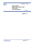


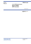


![Model ISC450G [Style: S2] Inductive Conductivity](http://vs1.manualzilla.com/store/data/005904832_1-e9e6bdf8409b6fd37a184b6e2701b530-150x150.png)

![Model DO402G Dissolved Oxygen Converter [Style: S3]](http://vs1.manualzilla.com/store/data/005725233_1-bd7e4c5bf258da59a958f30153ff00ea-150x150.png)