1
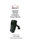
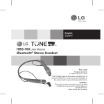
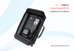
Beam Communications Pty Ltd
8 Anzed Court, Mulgrave
Victoria, Australia, 3170
Fixed Handsfree Car Kit
T: +61 3 8588 4500
F: +61 3 9560 9055
E: [email protected]
W: www.beamcommunications.com
RST620
USRQSG005001
Installation guidelines:
Routing Cables:
> Always protect equipment from dirt and moisture
> Ensure mounting surfaces are strong
> Allow for cooling space & driver/passenger leg room
> Ensure all wires are secure
> Always use the supplied mounting hardware.
> Ensure removal is easy (as above)
Use wiring troughs when available, to simplify cable
installation and to provide maximum protection for cables.
If wiring troughs are not available, route cables under the
carpet alongside the drive shaft hump and follow these
guidelines:
> Route cables so they are protected from pinching, sharp
edges, and crushing
> Where possible, avoid routing cables above the catalytic
converter
> Use grommets wherever a cable must pass through a hole
in a metal panel
> In a vehicle equipped with electronically controlled anti-skid
brakes (ABS), route all cables on the opposite side of the
vehicle from the braking modulator box to minimize any
possible interference.
> Keep all in-line connectors accessible.
Note: Only qualified people should install
communication equipment. For vehicle air bag
information contact the vehicle manufacturer.
Quick
Start
Guide
Thank you for purchasing your BEAM Fixed InVehicle Handsfree kit.
This QuickStart Guide lists the installation steps:
1. Installing your handset & holder
2. Installing your Hands Free Interface Unit (HFI)
3. Installing your Transceiver Module
4. Installing your Directional Microphone
5. Installing your Speaker
6. Installing your Antenna: refer to separate guide
7. Connecting Power
8. Testing & Operation
1
Package Contents
Before commencing installation ensure your package
has the following components:
1 x RST620 Hands Free Interface (HFI) module
1 x Intelligent Handset & cradle
1 x Speaker
1 x Microphone
1 x L-Band transceiver (9522B)
1 x L-Band transceiver bracket & Velcro fastener
1 x L-Band transceiver cable
1 x 3-wire Power cable harness & 2 Fuses
1 x Allen key
1 x Printed RST620 User Manual
Installing your handset & holder/hang-up cup
Mount the hang-up up of the Intelligent Handset so that the handset is within easy reach of the driver during
normal operation and will not interfere with driver or passenger comfort. Orient the handset hang-up cup vertically,
with the spring-loaded clip toward the front of the vehicle.
Allow enough room to:
> your handset needs to connect to the Hands Free
Interface (HFI).
> easily insert the handset into and remove it from
the hang-up cup
When selecting an installation location, please consider:
> Each mounting surface is strong enough to support
the handset
> Ensure that handset is within reach of the RST620
interface-unit (HFI).
RST62O Options & Accessories
714 Whip
Antenna
710 Iridium Helix
Antenna
More info @
www.beamcommunications.com
2
Installing your Interface box (HFI)
The best location for mounting the HFI is under the dashboard or front
seat within reaching distance of your handset (above) when in the cradle.
To install the box, follow these steps:
1. Using the HFI as a template, mark the screw hole locations.
2. Remove the bracket, and drill holes at the marked locations.
3. Mount using the six screws provided with the fuse kit.
RST620 HFI
3
Optimising Iridium performance
Iridium is a line-of-sight Satellite network, conditions that can
compromise the quality of the service you may receive include:
1. Obstructions: Provide the best satellite view for your antenna by removing all obstructions where possible
2. Cabling: Use the shortest cable length and the fewest number of connectors on all Iridium certified antenna cable runs
3. RF Interference: Install antenna as far away from other transmitters as possible.
Installing your Transceiver Module
Mount the Transceiver module in a safe location away from
driver obstruction.
Ensure the distance between the transceiver module and the
Hands Free Interface enables the D25 Connector cable to
reach both units.
Use the pre-assembled bracket (3x 4mm slots) and Velcro tape
supplied to conveniently attach the Transceiver module to a
fixed surface.
L-Band Transceiver
Setting up your BEAM RST620 Fixed Handsfree Car Kit
HFI Side 1
HFI Side 2
!
RED = +BATT (11 to 32 VDC)
BLACK = -BATT (GND)
GREEN = ACC PWR
4
5
CAUTION:
DO NOT connect power
to the battery until the
installation is complete.
Installing the Directional Microphone
The hands-free directional microphone must be properly positioned in the vehicle to ensure
optimum performance.
When selecting a location for the microphone, consider these guidelines:
> Mount the microphone near the centre of the vehicle, either on the driver-side sun visor or
on the head-liner above the driver.
> Do not position the microphone where it may be blocked by the visor.
> Position the microphone so that it faces the user of the mobile when the user is seated
normally.
> Do NOT position the microphone near a window or in any location where road noise or any
ambient background noise may be high (above 85 dB SPL).
> Do NOT position the microphone where it will be affected by the output of the speaker (see
below).
Installing the Speaker
1. Mount the speaker to the transmission hump or underneath
dashboard on passenger side.
2. Mount speaker so it faces AWAY from microphone - this can
cause “feedback” through the system.
3. To avoid damaging the cable, route the cable carefully to ensure
that it does not get crimped by any heavy objects or enclosures.
6
Installing your External Iridium Antenna
7
Connecting Power
See the specific “Iridium Antenna Installation Guide” manual or visit us @ www.beamcommunications.com
1. Ensure the power and Interface cable to the HFI will reach from the RST620 unit to the point at which vehicle
power is being sourced DO NOT connect to the HFI until after the installation is complete.
2. Route the power cable from the HFI to the connection point.
Note: To limit ground loops and high impedance ground paths, run the green/red-stripe and black wires
directly to the battery, or as close to the battery as possible. Use a grommet or other protection to prevent
wear on metal surfaces for these wires.
3. Prepare the fuse block. Remove all fuses, and tape them to their respective holders, before making any
connection. DO NOT insert fuses until you have completed and inspected all connections.
4. Connect the BLACK Ground wire to negative battery / vehicle chassis (if negatively grounded chassis).
5. Connect the RED +Battery wire to the vehicle + Battery (eg. +12V) via a 3A fuse.
6. Connect the GREEN Accessory wire to the vehicle accessory power, via a 1A fuse. (This may be connected to
Vehicle Ignition voltage if Accessory power is unavailable).
8
Testing & Operation
Once steps 1-7 have been completed, test the installation by following this checklist.
Antenna Cable
1. Ensure the Satellite terminal has power to the unit.
2. Ensure that the vehicle is located in an area where quality signal is available
3. Ensure that the Intelligent Handset is plugged into the HFI
4. Turn on the ignition to ACC or ON position
5. The handset should now be on (after few seconds), attempting to find Satellite network
6. Wait for the unit to register on the network (20 to 40 seconds).
7. You are now ready to make and receive calls.
info
ith
d w ndset
e
i
l
p
a
Sup 05A H
95
Checking performance after installation:
To confirm your car kit is working properly:
1. Make a call from the handset in the cradle and confirm operation.
2. Make a call to the handset and confirm operation.
Important Operational Notes
1. When the vehicle ignition is turned off, the handset will be turned off after a delay as follows: The unit will prepare to
turn-off phone after the first 5 seconds. The vehicle ignition can be returned to ACC / ON position during this time, and
the phone will remain on without phone power dropout. This is useful if the vehicle was inadvertently turned off during a
voice-call. If ACC remains off, then the Interface unit will also turn off after a further few seconds.
2. If during operation of the Hands free unit the unit either does not turn on or will not turn off, it is recommended to
follow these steps:
> Turn vehicle Accessories off
> Turn the terminal off
> Wait 10 seconds
> Turn on the vehicle Accessories once more.
3. If the power button is pressed after the accessories has already been turned off in the vehicle the telephone will
operate for a period of 20 minutes before the unit will power off. If after 19minutes a call is in progress the terminal will
stay on for another 20 minutes. This feature is to minimise drain on the battery.
4. The power to the terminal is dependent on the poser source chosen during installation. If power is required at all
times even when the vehicles turned off then the power should be connected to constant 11-32V DC input.
5. Be aware of the possibilities of this however flattening the vehicle battery.
Hands-free Interface LEDs
The Interface unit has a green status indicator (LED), which indicates:
Indictor state
State description
Flash (slow)
Unit is powered, transceiver not registered yet
Steady on
Transceiver registered
Flash (fast)
Call in progress