1
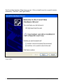
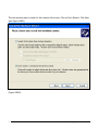
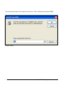
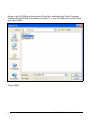
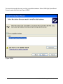
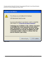
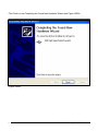
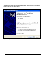
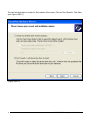
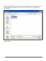
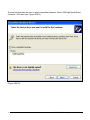
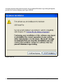
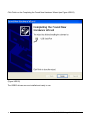
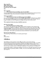
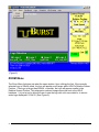
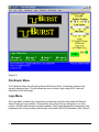
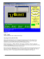
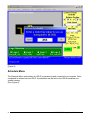
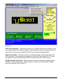
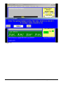
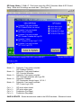
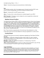
HDLG
HD/SD SDI
Logo Generator and
Color Bar Generator
Manual Version
1.00
BURST ELECTRONICS INC
ALBUQUERQUE, NM 87193 USA
(505) 898-1455 VOICE
Made in USA
(505) 890-8926 TECH SUPPORT
(505) 898-0159 FAX
www.burstelectronics.com
Hardware, software and manual copyright by Burst Electronics. All
rights reserved. No part of this publication may be reproduced or
distributed in any form or by any means without the written permission
of Burst Electronics Inc.
Introduction
Congratulations on your purchase of the Burst Electronics model HDLG digital logo
generator. Wehope that this manual will cover any questions you
may have concerning the operation of this product.
The HDLG overlays a 24-bit (full color) bitmap (BMP) image onto your SD/SDI or HD/SDI
video signal. HDLG can store up to four (4) digital logos in it’snon-volatile memory. The
HDLG can also generatea 720p/60 or 1080i/60 ColorBar digital video signal. The HDLG can
overlay any of the four saved logos onto the generated color bar signal.
The command interface software is called HDLogoGen. This software is designed to control
an HDLG from a MS Windows based PC environment. The program serves two primary
functions. First is to facilitate the transfer of logo graphics data to the HDLG hardware, and
second is to allow remote Graphical User Interface (GUI) control of the HDLG.
Support Features
Support for Windows XP/Vista.
Auto-detection of HDLG hardware.
USB
HDLogoGen emulates the image effects of your
displayed logo.
Ability to retrieve a logo stored within the HDLG
hardware.
A link to User’s Manual within Help.
Search for available USB (software controlled COM) ports.
Product Description
The HDLG SD/SDI or HD/SDI uses video input to generate logos on live video. The HDLG
can also generate its own video signal and key in any of the stored logos.
1
HDLG HD/SD SDI Logo/Color Bar Generator
Hardware Installation
Connect a SD/SDI or HD/SDI video source to the Video IN of the HDLG and connect the SDI
Loop Output to your monitor. Video will pass through the HDLG without power applied.
The SDI Output BNC is for video output for either video overlay of logo onto the incoming SDI
video source, or 1080i-60/702p-60 outputs when the HDLG Generator Function
has been selected from the front panel.
Place the HDLogoGen Program Files Installation CD into your CD-ROM drive. Plug in and
connect the 12Vdc wall module to the HDLG and turn power on. Connect the USB2.0 cable to
the computer and then to the HDLG hardware. A pop-up window appears stating New
Hardware Found (see Figure USB1)
(Figure USB1)
2
HDLG HD/SD SDI Logo/Color Bar Generator
The Found New Hardware Wizard pops up next. Click on Install from a list or specific location
(Advanced). Click Next. (see Figure USB2)
(Figure USB2)
3
HDLG HD/SD SDI Logo/Color Bar Generator
The next window asks to search for the location of the driver. Click on Don’t Search. Click Next
(see Figure USB3).
(Figure USB3)
4
HDLG HD/SD SDI Logo/Color Bar Generator
The next window asks for the location of the driver. Click on Browse (see Figure USB4)
(Figure USB4)
5
HDLG HD/SD SDI Logo/Color Bar Generator
Browse to the CD-ROM drive that has the HDLogoGen Installation Disk. Select D:\program
files\Burst\BG-HDLG\USB_Driver\ftdibus.inf (where “D” is your CD-ROM drive) and click Open
(see Figure USB5).
(Figure USB5)
6
HDLG HD/SD SDI Logo/Color Bar Generator
The next window asks the user to select compatible hardware. Select USB High Speed Serial
Converter and click Next (see Figure USB6).
(Figure USB6)
7
HDLG HD/SD SDI Logo/Color Bar Generator
A warning window stating that this driver has not passed Windows Logo testing will appear,
just click on Continue Anyway (see Figure USB7)
(Figure USB7)
8
HDLG HD/SD SDI Logo/Color Bar Generator
Click Finish on the Completing the Found New Hardware Wizard (see Figure USB8).
(Figure USB8)
9
HDLG HD/SD SDI Logo/Color Bar Generator
Windows will now show another Found New Hardware; USB Serial Port pop-up above the
Taskbar (see Figure USB9)
(Figure USB9)
10
HDLG HD/SD SDI Logo/Color Bar Generator
Windows will then restart the Found New Hardware Wizard. Select Install from a list or specific
location. Click Next (see Figure USB10).
(Figure USB10)
11
HDLG HD/SD SDI Logo/Color Bar Generator
The next window asks to search for the location of the driver. Click on Don’t Search. Click Next
(see Figure USB11).
(Figure USB11)
12
HDLG HD/SD SDI Logo/Color Bar Generator
Browse to the CD-ROM drive that has the HDLG Installation Disk. Select D:\program files\Burst
\BG-HDLG\USB_Driver\ftdiport.inf (where“D” is your CD-ROM drive) and click Open (see
Figure USB12).
(Figure USB12)
13
HDLG HD/SD SDI Logo/Color Bar Generator
The next window asks the user to select compatible hardware. Select USB High Speed Serial
Converter. Click Next (see Figure USB13).
(Figure USB13)
14
HDLG HD/SD SDI Logo/Color Bar Generator
A warning window stating that this driver has not passed Windows Logo testing will appear,
just click on Continue Anyway (see Figure USB14).
(Figure USB14)
15
HDLG HD/SD SDI Logo/Color Bar Generator
Click Finish on the Completing the Found New Hardware Wizard (see Figure USB15)
(Figure USB15)
The USB2.0 drivers are now installed and ready to use.
16
HDLG HD/SD SDI Logo/Color Bar Generator
Windows XP/Vista
Insert the Program Files disk into your CD-ROM drive (Windows may open a new window
displaying the contents of the CD-ROM. If this window doesn’t open, open Windows Explorer
and browse to your CD-ROM drive and double click the file called SETUP.EXE (application), or
click “Start”, “Run” and type D:\setup.exe (where “D” is your CD-ROM drive) then click OK.
Follow the on screen instructions to complete the installation. After the software installation is
complete, a new icon is placed on your desktop called HDLOGOGEN. Double click HDLG to
launch the HDLogoGen Command Interface.
What is HDLogoGen
HDLogoGen is a Windows based program to help operate the HD logo generator with a
personal computer. HDLogoGen can be divided into three areas: the Menu, the Relative
Screen Position, and the Control Panel (see Figure 1).
(Figure 1)
17
HDLG HD/SD SDI Logo/Color Bar Generator
Creating Logos
The HDLG uses a 24-bit, full color bitmap (BMP) as the logo image. The logo size must not
exceed 262144 pixels, Width evenly divisible by 4 and Height evenly divisible by 2. This does
seem a little complex, but follow these rules and you will be able to create just about any logo
image you like. If using Microsoft Paint (Paintbrush) to create a logo, the size and color settings
must be set. This is accomplished by clicking on Image from the Paintbrush menu, then
clicking on Attributes. (see Figure 2 & 3)
(Figure 2)
18
HDLG HD/SD SDI Logo/Color Bar Generator
(Figure 3)
Maximum color depth - 24-bit, full color
Maximum logo palette - 512 x 512 = 262144 pixels
For example, if your logo has a Width of 720 pixels (evenly divisible by 4), then the maximum
allowed Height is 256 pixels (evenly divisible by 2). Here are the rules:
·
·
·
Width evenly divisible by 4
Height evenly divisible by 2
Logo size (W x H) does not exceed 262144 pixels.
Minimum size of logo 32x32 is valid. 32 is evenly divisible by 4, and 32 is evenly divisible by 2.
Many different sizes of logos are can be created as long as the above rules are not violated.
Default Transparency - RGB = 255 (Red = 255, Green = 255, Blue = 255). To adjust the
background transparency of the logo, use the LOGO pull down menu and select the Color Key
R, G, B = (255,255,255)
Note: If a logo has a background value of 128 (grey) and you wish this to be transparent then
use the Color Key R, G, B = (255,255,255) under the Logo pull down menu and enter 128.
Return to the File pull down menu and click on Send Logo to HDLG. The background should
now be transparent.
To create an area of transparency within your logo, set the RGB value of the pixels to 128 (R =
128, Green = 128, and Blue = 128). This area will appear grey in both Paint and HDLG
19
HDLG HD/SD SDI Logo/Color Bar Generator
interface software, but once installed into the hardware, these pixels will appear clear. The
software also has the ability to change the Transparency Value. The number displayed in this
field converts this RGB value to transparent. For example, if you change this value to 128, then
all pixels with RGB = 128 (Red = 128, Green = 128 and Blue = 128) will become transparent.
This allows you to make any RGB value clear.
Note: For NTSC, when creating an area of black, we recommend using an RGB value of no
less than RGB = 25. A value of RGB = 25 will create black at 7.5IRE.
Note: For PAL, a value of RGB = 0 will create black at 0IRE.
Note: It is recommended that any horizontal line be at least 2 pixel to avoid flickering of
horizontal lines.
When finished creating the logo, save the image and close Paint. The logo is now ready to be
imported into HDLogoGen (see Open Logo File).
File Menu
The FILE Menu contains the links for sending and saving logos to the HDLG hardware. Also,
retrieving a logo from the HDLG hardware is located within File menu.
These links are as follows (see Figure 4).
(Figure 4)
20
HDLG HD/SD SDI Logo/Color Bar Generator
Open Logo File
Send Logo to HDLG
Get Logo From HDLG
Recent Logo Files (last eight)
Exit
Open Logo File
· This is the first step in installing a logo into the HDLG.
Clicking on the Open Logo File link will activate a standard Windows Browse dialog box where
a bitmap (BMP) image can be selected for installation into the HDLG hardware.
Send Logo to HDLG
· This is the second step in installing a logo into the HDLG.
Once you have opened your logo file, click on Send Logo to HDLG. The Send Logo to HDLG
link downloads the BMP image into the hardware and permanently saves the logo. After the
image is installed, the HDLG hardware can display that logo onto a video monitor.
This completes the two-step logo installation process.
Get Logo From HDLG
· This step allows you to retrieve a logo.
With this link, a logo that has been installed into the HDLG hardware can be retrieved and
saved onto the computer as a BMP file. Select the logo you wish to save, then click on Get
Logo From HDLG. The logo selected will then be downloaded (the selected logo will not be
visible during the download). When the download is complete a Windows File Open dialog
box will open. This is when you will choose a name and location for your saved logo file.
Recent Logo Files (History)
The recent Logo Files shows up to 8 recently opened logos.
Exit
Closes HDLG.
COM Menu
The COM menu allows selection of the USB port used to communicate with the
HDLG hardware. By default only physical COM ports are listed (commonly COM1 and COM2),
however, the software needs to be refreshed with the new USB to Serial port driver. First,
connect the USB cable to the HDLG and power up the unit (if this is your first time connecting
the unit to your computer, refer to USB Driver Installation). Click on Search for COM ports to
command the software to find the new USB port. Now click on COM again and select the newly
labeled COM port (commonly COM3 or COM4). Your unit is now ready to receive a new logo.
(See Figure 5).
21
HDLG HD/SD SDI Logo/Color Bar Generator
(Figure 5)
ZOOM Menu
The Zoom Menu link does just what the name implies. Upon clicking the link, if the currently
selected logo is 256x64 pixels, the logo will appear much larger within HDLG’s Relative Screen
Position. If the logo is larger than 256x64, or smaller, the logo will appear smaller in the
Relative Screen Position. This enlarged or reduced image cannot be sent to the HDLG
hardware. It is just a tool to allow the user to see the logo with a bit more detail or to see an
entire logo displayed if 512x512. (See Figure 6).
22
HDLG HD/SD SDI Logo/Color Bar Generator
(Figure 6)
Paintbrush Menu
The Paintbrush Menu link will call up Microsoft Windows Paint, (if installed), and input the
currently displayed logo. This link allows the user to select a logo using HDLG, then call
Paintbrush to edit the image.
Logo Menu
The Logo Menu contains links for selecting a stored logo and links that enable the Relative
Screen Position’s logo emulator. This emulator shows how the logo will appear on a video
monitor. With Mix and Intensity checked (enabled), HDLG approximates the transparency and
brightness level of the currently selected logo stored within the HDLG hardware. (See Figure 7)
23
HDLG HD/SD SDI Logo/Color Bar Generator
(Figure 7)
Logo1 – Logo4
These links allows a user to select a stored logo.
Color Key R, G, B= (255, 255, 255)
Opening this link allows the user to change the transparency value of the selected logo
background of the displayed logo on the Relative Screen Position. The R, G, B, value
determines a pixel value that will make the HDLG background clear.
Default Transparency - RGB = 255 (Red = 255, Green = 255, Blue = 255). To adjust the
background transparency of the logo, use the LOGO pull down menu and select the Color Key
R, G, B = (255,255,255) and enter your desired value.
Note: If a logo has a background value of 128 and you wish this to be transparent then use the
Color Key R, G, B = (255,255,255) under the Logo pull down menu and enter 128. Click on
Send Logo to HDLG. The background should now be transparent. (See Figure 8)
24
HDLG HD/SD SDI Logo/Color Bar Generator
(Figure 8)
Schedule Menu
The Schedule Menu works when an HDLG is powered up and connected to a computer. Once
a schedule is entered into the HDLG, the schedule can be sent to the HDLG hardware nonvolatile memory.
(See Figure 9)
25
HDLG HD/SD SDI Logo/Color Bar Generator
(Figure 9)
Schedule View (See Figure 10)
Schedule allows a user to setup a sequence of times when a logo would be displayed. Select
Schedule View. Within Schedule View there are four (4) vertical slider bars. Each of these
sliders (Start, T-ON, Repeat, End) control a value on the table in the center of the window.
26
HDLG HD/SD SDI Logo/Color Bar Generator
(Figure 10)
Start Slider – Tells HDLG at what time a logo cycle will start.
T-ON Slider – Tells HDLG how long a logo will be displayed during it’s display cycle.
Repeat Slider – Tells HDLG how long the ON/OFF cycle will be.
End Slider – Tells HDLG at what time a logo cycle will stop.
The LOGO field to the right side of this table allows the user to select which logo will be
displayed during that particular logo cycle. Any value from one (1) to four (4) can be inserted
into this field. This value corresponds to the logo memory location.
Calendar – A 7-day calendar that allows a user to select which day(s) of the week a particular
logo will be displayed. An “X” within a box means that on the selected day and time, a logo will
be displayed. The image in Figure 7 shows a sample schedule table that cycles through 4
different logos.
27
HDLG HD/SD SDI Logo/Color Bar Generator
Scan for Conflicts – This button will scan through the schedule table for any conflicts with
how the schedule cycle will run. Some example conflicts are; two logos being called up at the
same time, Start time begins at the exact same moment when End Time occurs.
Note: You must leave at least 15 seconds between one logo End Time and the next logo Start
Time to avoid schedule conflicts.
AutoScan – The check box called AutoScan will continually scan the table for conflicts while
you are configuring your schedule.
Save – This button will save any changes made to the Schedule View Table. Save must be
pressed before this window is closed to avoid losing any changes made to this table.
Note: To save Schedule View Table to the HDLG go to the HDLG Setup pull down menu and
select send Timing Schedule. This will save the schedule into the HDLG’s non-volatile
memory. See HDLG Setup.
Exit –This button will close this window and return you to HDLG. If Exit is performed before
Save is pressed, any changes made to Schedule will be lost.
Schedule Lock
Schedule Lock locks the schedule to prevent accidental changes to the schedule view.
Scheduler ON/OFF
This button turns on the Scheduler when the proper GPI Mode Setup is set to run from the
Windows GUI. (See GPI Setup; Mode = ?; Crtl = ? ) HDLG can then be disconnected from the
PC and the Schedule will continue to run.
The TAKE switch on the front panel of the HDLogogen Window will operate normally in GPI
Setup: Mode=1, Ctrl=1. This is the default GPI Setup setting. (See GPI Setup)
Front Panel Lock
This button locks out all functions of the HDLogoGen Control Panel. Moving the logo on the
Relative Screen Position window is deactivated. The Logo Selection buttons remain active.
Manual operation of the HDLG hardware is also active.
(See Control Panel)
HDLG Setup
The HDLG Setup menu allows the user to send the HDLG Schedule to the non-volatile
memory. This allows for automatic operation in remote areas. The HDLG Setup menu
includes a link to update the time and date from the computer, regional daylight savings time
setup, and GPI setup options. (See Figure 11)
28
HDLG HD/SD SDI Logo/Color Bar Generator
(Figure 11)
Send Timing Schedule – This button commits your configured schedule to be loaded into the
non-volatile memory of the HDLG hardware. The schedule can then be activated via the front
panel switch or by using the Scheduler ON/OFF button under the Schedule Menu.
Send Time and Date – This button allows for manually updating of the time and date of the
HDLG hardware. The updated time will appear on the Control Panel of the HDLG. The date
will appear on the line above the Send Com: line on the bottom of the HDLG window.
Daylight Savings Time Setup – This button opens settings for loading the daylight savings
time data. This is loaded into the HDLG hardware so the time can be adjusted for daylight
savings automatically. (See Figure 12)
29
HDLG HD/SD SDI Logo/Color Bar Generator
(Figure 12)
30
HDLG HD/SD SDI Logo/Color Bar Generator
GPI Setup; Mode = ?; Crtl = ? –This button opens the HDLG Scheduler Mode & GPI Control
Setup. Mode and Ctrl settings are made here. (See Figure 13)
(Figure 13)
Mode = 1 – Scheduler: Front panel controlled
GPI: Disabled (Default)
Mode = 2 – Scheduler: Front panel disabled
GPI: Controls Scheduler.
Mode = 3 – Scheduler: Front panel controlled
GPI: Overrides scheduler with Logo ON
Mode = 4 – Scheduler; Disabled
GPI: Sequences through Logos 1-2-3-4-1
Mode = 5 – Scheduler: Front panel controlled
GPI: Forces Logo 4 ON
Ctrl = 1 –
Ctrl = 2 –
Ctrl = 3 –
Ctrl = 4 –
GPI active when closed
GPI active when open
Pushbutton (Pos Edge)
Pushbutton (Neg edge)
SAVE & UPDATE – Saves the selections made to the HDLG hardware. Otherwise it saves
31
HDLG HD/SD SDI Logo/Color Bar Generator
the default settings: Mode = 1, Ctrl = 1.
Cancel – Cancels the settings and returns selections to default settings.
Help
The Help Menu provides a link to the operator manual, information about the HDLG, and a
button to view the Copyright date of the HDLG software and firmware version.
Manual – Provides a link to the PDF operator manual.
About – Provides a link to contact information for technical support for your HDLG.
HDLG Copyright – This button is used to display the current copyright date, software and
firmware versions of the HDLG.
Relative Screen Position
The Relative Screen Position (RSP) in HDLG gives an approximation of how a logo will appear
on a digital video monitor. Features emulated in the RSP are, appearance of a logo, position of
a logo, mix ratio , and fade speed. Upon first launching HDLogoGen, the logo BURST.BMP is
displayed on the RSP. This does not mean that BURST.BMP is a logo currently installed in the
HDLG hardware (unless this is the first time the HDLG hardware is being used, in that case,
the BURST.BMP file is the logo installed into the HDLG hardware). To change to a different
logo, see File Menu-Open Logo. Position of a logo can be accomplished by dragging the logo,
with a mouse, to any place within RSP.
Note: These functions are approximations of how the logo is being displayed on a video
monitor and should not be used as calibration for the logo’s appearance on a video monitor.
Control Panel
The Control Panel gives a user access to adjustments regarding logo Fade Speed, Mix Ratio,
and Take.
Fade Speed – A slider bar to change the duration of time it takes for a logo to transition
between being displayed and not being displayed. Fully left fades at about 5 seconds, fully
right fades at about 0.05 seconds.
Mix Ratio – A slider bar to change the transparency of a displayed logo. Fully left is
transparent, fully right is solid.
Take – A button to toggle the display of a logo on a video monitor (if the button is gray, the logo
is not being displayed. If the button is green, the logo is being displayed.
Logo Selection
At the bottom of HDLogoGen are a series of 4 radio buttons that are labeled Logo 1 through
Logo 4. Selecting any of these radio button will call the logo stored in that location to be the
currently displayed logo (displayed if the Take button is green, or the front panel LED labeled
ACTIVE is on). Beneath each of these radio buttons is displayed a logo file name that has
been loaded into HDLG. (See Figure 14)
32
HDLG HD/SD SDI Logo/Color Bar Generator
(Figure 14)
33
HDLG HD/SD SDI Logo/Color Bar Generator
HDLG – Hardware
This section of the manual will explain the functions of the HDLG Front Panel switches.
HDLG Front Panel
(Figure 15)
1080i/Live Feed/720p—This switch allows the user to choose between HDLG
Generator functions and the digital logo overlay mode. The generator functions allow overlay
of the selected logo onto internally generated 1080i-60 and 720p-60 color bars. The 1080i (top)
position activates the 1080i-60 bar generator. The Live Feed (middle) position allows for the
incoming video signal source to overlay the selected logo. The 720p (bottom) position
activates the 720p-60 bar generator for overlay of the selected logo.
Speed – Adjusts the rate at which a logo will transition between on and off when a Take
function is performed. Pushing the switch up will cause a faster transition, pushing the switch
down will cause a slower transition. The range of speed is from 0.05 seconds to approximately
5 seconds.
Mix – Adjusts the transparency of a logo. Pushing the switch up causes the logo to be more
solid, pushing the switch down causes the logo to be more transparent.
- The left/right arrow switch is used to change the logo position horizontally.
- The up/down arrow switch is used to change the logo position vertically.
34
HDLG HD/SD SDI Logo/Color Bar Generator
Take – This switch has two functions, the first function is a toggle between a logo being
displayed and not being displayed. Push the switch up to accomplish this toggle. The second
function is to force the HDLG into a Schedule Cycle (See GPI Setup; Mode = ?; Crtl = ?).
The GPI Setup; Mode =1; Ctrl = 1 are the default settings which will allow operation of the front
panel Take switch to start the scheduler. Push the switch down (the switch stays down) to start
the internal counter for starting the Scheduler.
Logo – This switch allows the user to select the desired logo (1-4) to be displayed using
the LED Tower as an indicator.
LED Tower – This is an LED that indicates which logo is currently being displayed.
The
tower is labeled 4 on top and 1 on the bottom to indicate which logo is being displayed
Bug - Indicates the selected logo is being displayed.
(LED on and the logo is being
displayed, LED off and the logo is not displayed).
HD/SD –
The LED is Green indicating the input video signal is in the SD-SDI format. The
LED is Red indicating HD-SDI formats.
Power—ON/OFF power switch.
Up position turns power ON, Down
position turns power off.
HDLG Rear Panel
12Vdc – Power connector for the HDLG (see Specifications for power requirements).
USB – Single USB2.0 compatible port.
SDI Input – This is the input BNC for SDI video.
SDI Loop Output – This is the BNC connection for video loop through when the
HDLG is not turned on. When the HDLG is on, the incoming video will be processed to overlay
the selected logo.
SDI Output – This BNC is for SDI video output for either video overlay of logo onto the
incoming SDI video source, or 1080i-60/720p-60 outputs when the HDLG Generator Function
has been selected from the front panel.
EXT Clock/GPI Input – A 6 pin Phoenix connector to attach an external 1pps
reference from a GPS receiver to update time data and to receive GPI Input for controlling the
35
HDLG HD/SD SDI Logo/Color Bar Generator
logo scheduler.
EXT Clock – The External Clock is a 1pps reference to synchronize the HDLG’s internal clock.
Burst Electronics Inc has used the Tiny Tools Time Sync Plus from Broadcast Tools, Inc.
(www.broadcasttools.com) to input 1pps.
GPI Input – The GPI Input can be a TTL low or a TTL high to trigger the GPI. The setting on
the GPI Mode Setup should be configured to accept the proper TTL Condition. (See Figure 10)
Specifications
Power:
9 to 15 volts DC at 250mA (Polarity insensitive) or via 120 volt AC to 12 volt DC
converter (included with the HDLG).
Size:
5.6W x 1.5H x 7.3D inches.
Video:
Input – SD/SDI or HD/SDI, SMPTE 259M,SMPTE 274M, SMPTE 296M
Output -- Generate Mode 1080i/60, 720p/60 Digital Color Bars.
Logo:
16 million color (24-bit) LOGOS, 512 pixels wide by 512 pixels high.
Storage:
Up to 4 logos
Interface: USB2.0
Accessories:
3 foot USB2.0 cable
Program/Driver Installation Disk
120Vac – 12Vdc wall module
Mated pair for GPI/Clock connector
36
HDLG HD/SD SDI Logo/Color Bar Generator